HM-BT4502(A) V1.1 1/ 15 www.hoperf.com Bluetooth Low Energy (BLE) Pass-through Module Specification HM-BT4502(A) HM-BT4502 HM-BT4502A

Welcome message from author
This document is posted to help you gain knowledge. Please leave a comment to let me know what you think about it! Share it to your friends and learn new things together.
Transcript
HM-BT4502(A) V1.1
1/ 15 www.hoperf.com
Bluetooth Low Energy (BLE)
Pass-through Module Specification
HM-BT4502(A)
HM-BT4502
HM-BT4502A
HM-BT4502(A) V1.1
2/ 15 www.hoperf.com
Table of Contents
1 Product Overview ......................................................................................................... 3
2 Module Features ........................................................................................................... 3
3 Electrical Characteristics .............................................................................................. 4
4 Module Function Description ........................................................................................ 5
5 Application Schematic .................................................................................................. 6
6 Module Pins .................................................................................................................. 7
6.1 Module Pins Distribution ........................................................................................... 7
6.2 Module Pins Definition .............................................................................................. 8
7 Module Size .................................................................................................................. 9
8 Additional Information ................................................................................................. 11
HM-BT4502(A) V1.1
3/ 15 www.hoperf.com
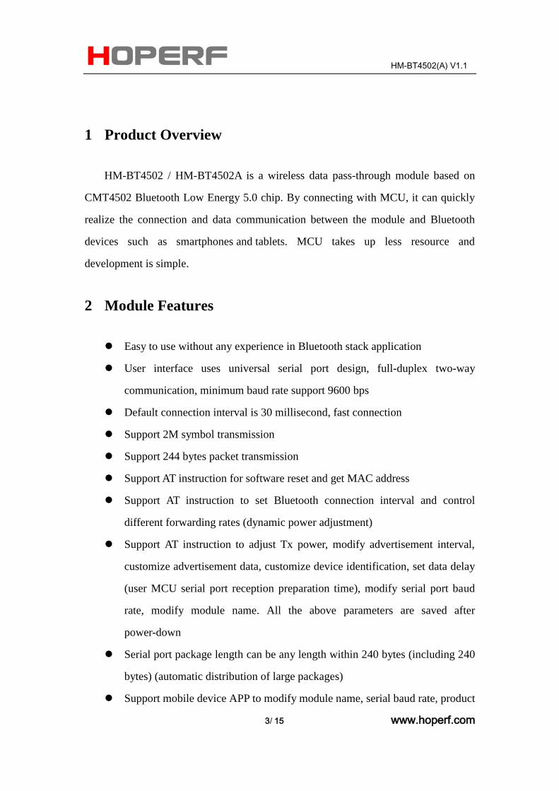
1 Product Overview
HM-BT4502 / HM-BT4502A is a wireless data pass-through module based on
CMT4502 Bluetooth Low Energy 5.0 chip. By connecting with MCU, it can quickly
realize the connection and data communication between the module and Bluetooth
devices such as smartphones and tablets. MCU takes up less resource and
development is simple.
2 Module Features
Easy to use without any experience in Bluetooth stack application
User interface uses universal serial port design, full-duplex two-way
communication, minimum baud rate support 9600 bps
Default connection interval is 30 millisecond, fast connection
Support 2M symbol transmission
Support 244 bytes packet transmission
Support AT instruction for software reset and get MAC address
Support AT instruction to set Bluetooth connection interval and control
different forwarding rates (dynamic power adjustment)
Support AT instruction to adjust Tx power, modify advertisement interval,
customize advertisement data, customize device identification, set data delay
(user MCU serial port reception preparation time), modify serial port baud
rate, modify module name. All the above parameters are saved after
power-down
Serial port package length can be any length within 240 bytes (including 240
bytes) (automatic distribution of large packages)
Support mobile device APP to modify module name, serial baud rate, product
HM-BT4502(A) V1.1
4/ 15 www.hoperf.com
identification code, and customize advertisement content and advertisement
period. These settings can be saved after power-down
Support mobile device APP to reset module and set Tx power
Support mobile device APP to adjust Bluetooth connection interval. The
setting can not to be saved after power down
Support anti-hijacking password settings, modification and recovery. Prevent
malicious third party connections. Users can also not use them
Advertisement Content prompt the module real-time system status, including
battery power, custom device identification code (suitable for advertisement
application)
Support internal RTC (real-time clock)
Acquired BQB Certification
Acquired FCC/CE/IC/SRRC Certification
3 Electrical Characteristics
Working voltage: 1.8V-3.6V
Working temperature: - 20℃~+85℃
Modulation mode: GFSK (Gaussian Frequency Shift Keying)
Modulation frequency: 2402MHz-2480MHz
Transient current of receiving data: less than 8mA@3V
Transient current of sending data: less than 8mA@3V@0dBm
Current in the low power mode: less than 4uA@3V
Tx power: - 20dBm ~+8dBm
Rx sensitivity: -97dBm
HM-BT4502(A) V1.1
5/ 15 www.hoperf.com
4 Module Function Description
After the module starts, it advertises automatically. The opened specific APP on
the mobile phone will scan and connect it. After successful connection, it can be
operated through BLE protocol. User-controlled MCU can realize the communication
with the mobile device through the serial port of the module. Users can also manage
and control some communication parameters through the specific interface
instruction.
User data format is defined by upper application program. Mobile devices can
write to the module through APP, and the written data will be sent to the user's MCU
through the module's external interface. When the module external interface receives
the data package from the external MCU, it will automatically forward it to the
connected mobile device. Users need to design the main MCU code and the smart
mobile device APP.
HM-BT4502(A) V1.1
6/ 15 www.hoperf.com
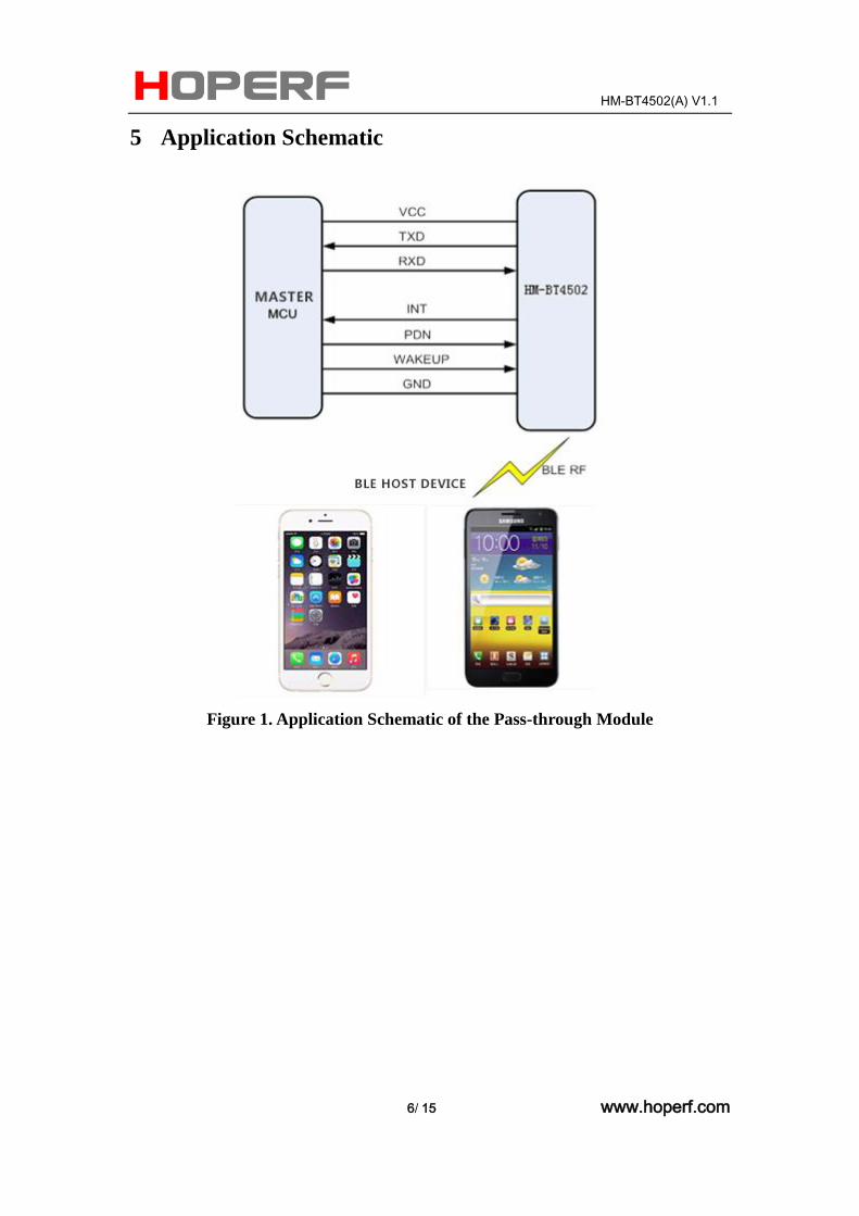
5 Application Schematic
Figure 1. Application Schematic of the Pass-through Module
HM-BT4502(A) V1.1
7/ 15 www.hoperf.com
6 Module Pins
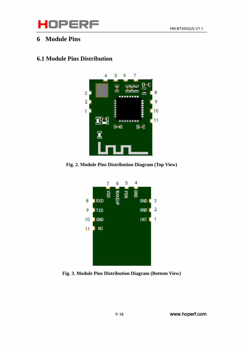
6.1 Module Pins Distribution
Fig. 2. Module Pins Distribution Diagram (Top View)
Fig. 3. Module Pins Distribution Diagram (Bottom View)
HM-BT4502(A) V1.1
8/ 15 www.hoperf.com
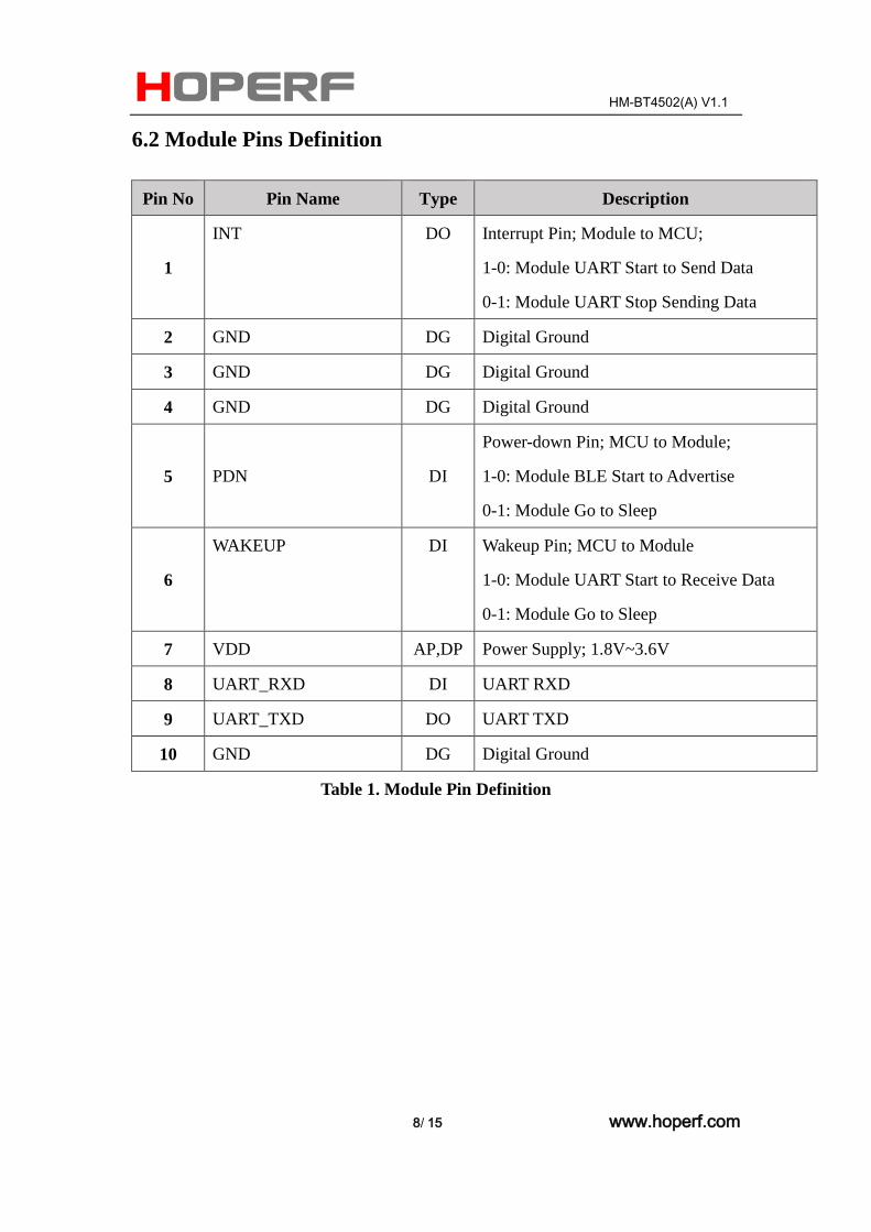
6.2 Module Pins Definition
Pin No Pin Name Type Description
1
INT DO Interrupt Pin; Module to MCU;
1-0: Module UART Start to Send Data
0-1: Module UART Stop Sending Data
2 GND DG Digital Ground
3 GND DG Digital Ground
4 GND DG Digital Ground
5 PDN DI
Power-down Pin; MCU to Module;
1-0: Module BLE Start to Advertise
0-1: Module Go to Sleep
6
WAKEUP DI Wakeup Pin; MCU to Module
1-0: Module UART Start to Receive Data
0-1: Module Go to Sleep
7 VDD AP,DP Power Supply; 1.8V~3.6V
8 UART_RXD DI UART RXD
9 UART_TXD DO UART TXD
10 GND DG Digital Ground
Table 1. Module Pin Definition
HM-BT4502(A) V1.1
9/ 15 www.hoperf.com
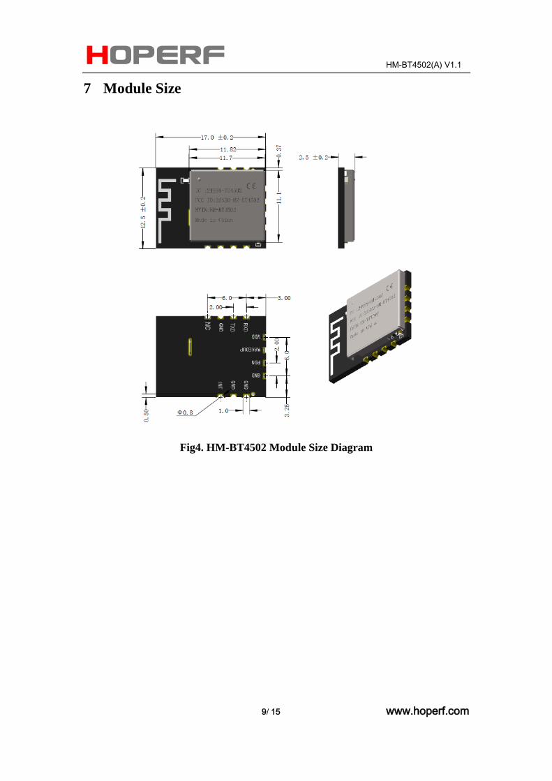
7 Module Size
Fig4. HM-BT4502 Module Size Diagram
HM-BT4502(A) V1.1
10/ 15 www.hoperf.com
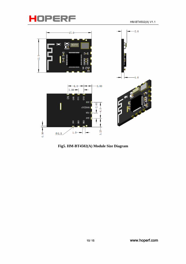
Fig5. HM-BT4502(A) Module Size Diagram
HM-BT4502(A) V1.1
11/ 15 www.hoperf.com
8 Additional Information
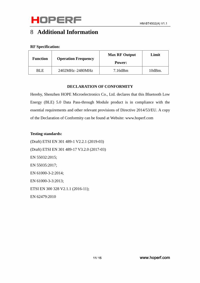
RF Specification:
Function Operation Frequency Max RF Output
Power:
Limit
BLE 2402MHz–2480MHz 7.16dBm 10dBm.
DECLARATION OF CONFORMITY
Hereby, Shenzhen HOPE Microelectronics Co., Ltd. declares that this Bluetooth Low
Energy (BLE) 5.0 Data Pass-through Module product is in compliance with the
essential requirements and other relevant provisions of Directive 2014/53/EU. A copy
of the Declaration of Conformity can be found at Website: www.hoperf.com
Testing standards:
(Draft) ETSI EN 301 489-1 V2.2.1 (2019-03)
(Draft) ETSI EN 301 489-17 V3.2.0 (2017-03)
EN 55032:2015;
EN 55035:2017;
EN 61000-3-2:2014;
EN 61000-3-3:2013;
ETSI EN 300 328 V2.1.1 (2016-11);
EN 62479:2010
HM-BT4502(A) V1.1
12/ 15 www.hoperf.com
Manufacturer's Name: Shenzhen HOPE Microelectronics Co., Ltd.
Bluetooth Low Energy (BLE) 5.0 Data Pass-through Module
Model Number: HM-BT4502
Operating Temperature: -40℃~+125℃ (BLE Chip Only)
1. The device complies with RF specifications when the device is used at 20cm from
your body.
2. This product can be used across all EU member states.
Care for the environment! Must not be discarded with household waste!
This module is intended for OEM integrator. The OEM integrator is still responsible
for the FCC compliance requirement of the end product which integrates this module.
20cm minimum distance has to be able to be maintained between the antenna and the
users for the host this module is integrated into. Under such configuration, the FCC
radiation exposure limits set forth for an population/uncontrolled environment can be
satisfied. Antenna used should be limited to same type with equal or lesser antenna
gain.
According to FCC Part 15 Subpart C Section 15.212, the radio elements of the
modular transmitter must have their own power supply. However, due to there is no
power supply for this BLE Module, this module is granted as a Limited Modular
Approval. When this BLE Module is installed into the end product, a Class II
Permissive Change or a New FCC ID submission is required to ensure the full
compliance of FCC relevant requirements.
HM-BT4502(A) V1.1
13/ 15 www.hoperf.com
FCC Caution:
Any changes or modifications not expressly approved by the party responsible for
compliance could void the user's authority to operate this equipment.
This device complies with Part 15 of the FCC Rules. Operation is subject to the
following two conditions:
(1) This device may not cause harmful interference, and
(2) this device must accept any interference received, including interference that may
cause undesired operation.
This device and its antenna(s) must not be co-located or operating in conjunction with
any other antenna or transmitter. 15.105 Information to the user. (b) For a Class B
digital device or peripheral, the instructions furnished the user shall include the
following or similar statement, placed in a prominent location in the text of the
manual:
Note: This equipment has been tested and found to comply with the limits for a Class
B digital device, pursuant to part 15 of the FCC Rules. These limits are designed to
provide reasonable protection against harmful interference in a residential installation.
This equipment generates, uses and can radiate radio frequency energy and, if not
installed and used in accordance with the instructions, may cause harmful interference
to radio communications. However, there is no guarantee that interference will not
occur in a particular installation. If this equipment does cause harmful interference to
radio or television reception, which can be determined by turning the equipment off
and on, the user is encouraged to try to correct the interference by one or more of the
following measures:
—Reorient or relocate the receiving antenna.
—Increase the separation between the equipment and receiver.
—Connect the equipment into an outlet on a circuit different from that to which the
receiver is connected.
—Consult the dealer or an experienced radio/TV technician for help.
HM-BT4502(A) V1.1
14/ 15 www.hoperf.com
1. This LMA does not have RF shielding and is tested and approved as standalone
configuration, additional evaluation may be required for any system integrated this
radio module.
2. The modular transmitter doesn’t have its own power supply regulation, it’s
provided by host.
Radiation Exposure Statement: This equipment complies with FCC radiation
exposure limits set forth for an uncontrolled environment.
This transmitter must not be co-located or operating in conjunction with any other
antenna or transmitter.
The availability of some specific channels and/or operational frequency bands are
country dependent and are firmware programmed at the factory to match the intended
destination. The firmware setting is not accessible by the end user. The final end
product must be labelled in a visible area with the following: “Contains Transmitter
Module 2ASEO-HM-BT4502”
IC Caution:
This device complies with Industry Canada license-exempt RSS standard(s).
Operation is subject to the following two conditions:
(1) This device may not cause interference,
(2) This device must accept any interference, including interference that may cause
undesired operation of the device.
Le présent appareil est conforme aux CNR d'Industrie Canada applicables aux
appareils radio exempts de licence. L'exploitation est autorisée aux deux conditions
suivantes: (1) l'appareil ne doit pas produire de brouillage, et (2) l'utilisateur de
l'appareil doit accepter tout brouillage radioélectrique subi, même si le brouillage est
susceptible d'en compromettre le fonctionnement.
HM-BT4502(A) V1.1
15/ 15 www.hoperf.com
HOPE MICROELECTRONICS CO., LTD.
Add: 2/F, Building 3, Pingshan Private Enterprise
Science & Technology Park, Xili Town, Nanshan
District, Shenzhen, Guangdong, China 518057
Tel: 86-755-82973805
Fax: 86-755-82973550
Email: [email protected]
Website: http://www.hoperf.com
This document may contain preliminary information and is subject to
change by Hope Microelectronics without notice. Hope Microelectronics
assumes no responsibility or liability for any use of the information
contained herein. Nothing in this document shall operate as an express or
implied license or indemnity under the intellectual property rights of Hope
Microelectronics or third parties. The products described in this document
are not intended for use in implantation or other direct life support
applications where malfunction may result in the direct physical harm or
injury to persons. NO WARRANTIES OF ANY KIND, INCLUDING, BUT
NOT LIMITED TO, THE IMPLIED WARRANTIESOF
MECHANTABILITYORFITNESSFORAARTICULARPURPOSE, ARE
OFFERED IN THIS DOCUMENT. ©2006, HOPE MICROELECTRONICSCO., LTD. All rights reserved.
Related Documents