Designing and calculating f or flexible Horizonta l L if e li nes ba se d on de si gn c od e CSA Z259.16 By HOE Yee Pin and Dr. GOH Yang Miang Introduction This article uses two worked examples to illus trate the fundamental design approach and calculations of a Horizontal Lifeline (HLL) systems based on the design code Canadian Standards Association Z259.16. The upcoming Singapore Standard on “Specification for Design of Active Fall Protection Systems” is based on the CSA Z259.16. The authors are members of the Working Group for this upcoming Singapore Standard. Horizontal Lifelines (HLL) are commonly used to protect users in a fall Falling from heights is the leading cause of workplace fatalities in Singapore (Ministry of Manpower 2013). Efforts to mitigate this risk has resulted in increased use of fall protection systems. One of the fall protection systems commonly used in the construction and maintenance industries is horizontal Lifelines (HLLs). A HLL is a component that extends horizontally from one end anchorage to another and consists of a flexible line made from wire, fibre rope, wire rope, or rod, complete with end terminations (Canadian Standards Association 2004). It provides a continuous anchorage line to which users can attach their lanyards and other fall arrest equipment (Figure 1). Figure 1: A typical Horizontal Lifeline (HLL) System and its parameters

Welcome message from author
This document is posted to help you gain knowledge. Please leave a comment to let me know what you think about it! Share it to your friends and learn new things together.
Transcript
7/24/2019 HLL Basic Calculation
http://slidepdf.com/reader/full/hll-basic-calculation 1/10
Designing and calculating for flexible
Horizontal Lifelines based on design code
CSA Z259.16By HOE Yee Pin and Dr. GOH Yang Miang
Introduction
This article uses two worked examples to illustrate the fundamental design approach and calculations
of a Horizontal Lifeline (HLL) systems based on the design code Canadian Standards Association
Z259.16. The upcoming Singapore Standard on “Specification for Design of Active Fall Protection
Systems” is based on the CSA Z259.16. The authors are members of the Working Group for this
upcoming Singapore Standard.
Horizontal Lifelines (HLL) are commonly used to protect users in a fall
Falling from heights is the leading cause of workplace fatalities in Singapore (Ministry of Manpower
2013). Efforts to mitigate this risk has resulted in increased use of fall protection systems. One of the
fall protection systems commonly used in the construction and maintenance industries is horizontal
Lifelines (HLLs).
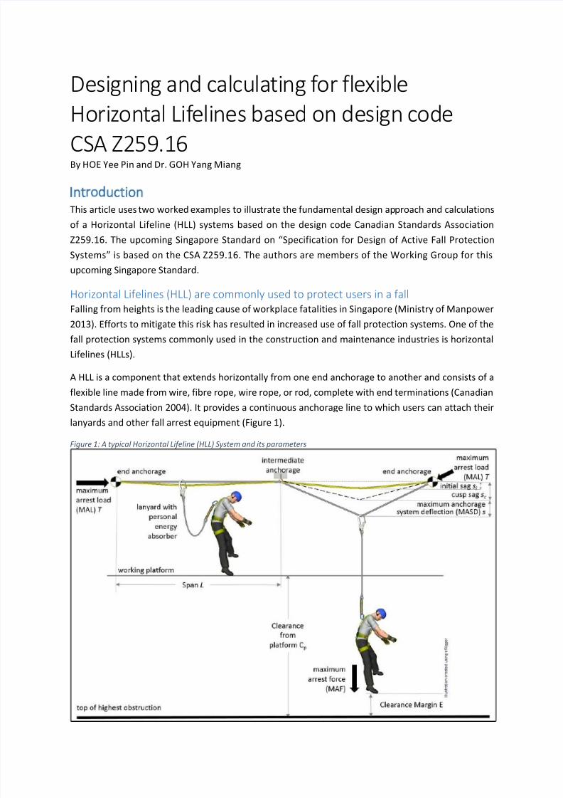
A HLL is a component that extends horizontally from one end anchorage to another and consists of a
flexible line made from wire, fibre rope, wire rope, or rod, complete with end terminations (Canadian
Standards Association 2004). It provides a continuous anchorage line to which users can attach their
lanyards and other fall arrest equipment (Figure 1).
Figure 1: A typical Horizontal Lifeline (HLL) System and its parameters

7/24/2019 HLL Basic Calculation
http://slidepdf.com/reader/full/hll-basic-calculation 2/10
Non-manufactured HLL systems more widely used than Manufactured HLL systems
HLLs can be permanent or temporary, and either a manufactured or non-manufactured system.
Manufactured fall arrest system refers to a complete system designed by a manufacturer. In contrast,
non-manufactured system refers to a system that is not designed by a manufacturer but may or may
not be designed by a Professional Engineer.
Non-manufactured systems are usually assembled from separate fall arrest system components and
can be from different manufacturers.
Non-manufactured systems are more commonly used than manufactured systems in the Singapore
construction industry (Hoe, Goh, et al. 2012). However, non-manufactured systems are more
vulnerable to component incompatibility and require more considerations to ensure effectiveness of
the system.
Critical for Engineers to properly design non-manufactured HLL systems
In Singapore, it is common practice to mitigate this risk by engaging a Professional Engineer (PE) to
design the HLLs. Based on a study by Hoe et al. (2012), 3 out of 5 fall arrest systems sampled from the
construction industry were designed and endorsed by PEs. Since non-manufactured HLLs are
prevalent and PE design usually comes with the HLLs, it is imperative that PEs properly design HLL
systems to function effectively.
A properly designed HLL protects users and complies with the legal
requirements
Common design mistakes
The purpose of a HLL (or any other fall arrest system) is to minimize injury to the users in the event of
a fall. Two common mistakes designers make are
1) only considering the strength aspects of the anchorages and the HLL components but
neglecting to evaluate the effects on the user(s) e.g. Maximum Arrest Force (MAF), and
2) using static analysis that ignored the dynamic force component generated in a fall.
These mistakes had led to strength requirements being grossly underestimated and critical safety
factors being neglected in the design (Wang, Hoe, et al. 2014).
The essential design criteria for an effective HLL
With reference to Figure 1, for a HLL system to be effective in protecting user(s), the following criteria
have to be met:
(i) system components and its anchorages are of adequate strength to withstand the
Maximum Arrest Load (MAL) or Maximum Arrest Force (MAF) to prevent failure;
(ii) Maximum Arrest Force (MAF) experienced by the user(s) is within acceptable limits to
minimize the probability of injuries;
(iii) clearance height required in a fall is less than clearance available to prevent the user(s)from hitting the ground or an obstruction in the fall path.
7/24/2019 HLL Basic Calculation
http://slidepdf.com/reader/full/hll-basic-calculation 3/10
Compliance with legal requirements
At the same time, the Workplace Safety and Health (Work At Heights) Regulations 2013 Regulation 11
requires that a fall arrest system
(a) is of good construction, sound material and adequate strength,
(b) incorporates a suitable means of absorbing energy and limiting the forces on a user’s body,
and
(c) in the event of a fall, there is enough fall clearance available to prevent the user from hitting
an object, the ground or other surfaces.
Worked Example 1: Single span HLL single user
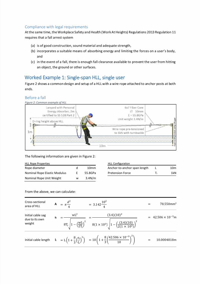
Figure 2 shows a common design and setup of a HLL with a wire rope attached to anchor posts at both
ends.
Before a fallFigure 2: Common example of HLL
The following information are given in Figure 2:
HLL Rope Properties HLL Configuration
Rope diameter d 10mm Anchor-to-anchor span length L 10m
Nominal Rope Elastic Modulus E 55.8GPa Pretension Force Ti 1kN
Nominal Rope Unit Weight w 3.4N/m
From the above, we can calculate:
Cross-sectional
area of HLL A =
4 = 3.142
104
= 78.550mm2
Initial cable sag
due to its own
weight
si =wL
8T 1 − wL2T
=(3.4)(10)
8(1 × 10) 1 − (3.4)(10)
2(1 × 10)
= 42.506 × 10m
Initial cable length li = L 1 +8
3s
L = 10 1 +
8
342.506 × 10
10 = 10.0004818m
7/24/2019 HLL Basic Calculation
http://slidepdf.com/reader/full/hll-basic-calculation 4/10
Unstressed HLL
cable length lo
=l
1 + TAE
=10.0004818
1 + 1 × 10(78.55 × 10)(55.8 × 10)
= 9.998200715m
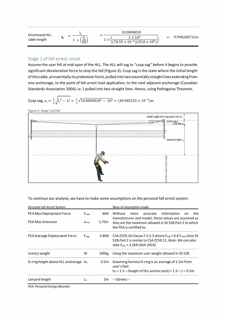
Stage 1 of fall arrest: onset
Assume the user fell at mid-span of the HLL. The HLL will sag to “cusp sag” before it begins to provide
significant deceleration force to stop the fall (Figure 3). Cusp sag is the state where the initial length
of the cable, at essentially its pretension force, pulled into two essentially straight lines extending from
one anchorage, to the point of fall arrest load application, to the next adjacent anchorage (Canadian
Standards Association 2004) i.e. li pulled into two straight lines. Hence, using Pythagoras Theorem,
Cusp sag, sc = l − L =
√ 10.0004818 − 10 = (49.082155 × 10)m
Figure 3: Stage 1 of Fall
To continue our analysis, we have to make some assumptions on the personal fall arrest system.
Personal Fall Arrest System Basis of assumption made
PEA Max Deployment Force Fmax 6kN Without more accurate information on the
manufacturer and model, these values are assumed as
they are the maximum allowed in SS 528:Part 2 to whichthe PEA is certified to.
PEA Max Extension xmax 1.75m
PEA Average Deployment Force Favg 4.8kN CSA Z259.16 Clause 7.3.3.2 where Favg = 0.8 Fmax since SS
528:Part 2 is similar to CSA Z259.11. Note: We can also
take F avg = 3.2kN (Goh 2014)
User(s) weight W 100kg Using the maximum user weight allowed in SS 528.
D-ring height above HLL anchorage hD 0.5m Assuming harness D-ring is an average of 1.5m from
user’s feet.
hD = 1.5 – (height of HLL anchor post) = 1.5 – 1 = 0.5m
Lanyard length Ly 2m -- (Given) --
PEA: Personal Energy Absorber
7/24/2019 HLL Basic Calculation
http://slidepdf.com/reader/full/hll-basic-calculation 5/10
We can now calculate the Free Fall (FF) experienced by the user,
FF = h + s − + L = 0.5 + (49.082 × 10) + 2 = 2.549m
Stage 2 of fall arrest: energy absorption
The user’s fall is now being arrested. Energy analysis is used as per CSA Z259.16 Clause 9.3.3.
Stage 2.1: Kinetic energy generated in the fall will be absorbed by the elongation or sagging of the HLL
cable (beyond cusp sag). This midpoint sagging, s, will continue until the force in the lanyard, F, reaches
the deployment force of the lanyard’s Personal Energy Absorber (PEA).
Stage 2.2: At the PEA’s deployment force, the PEA will deploy and is assumed to be solely responsible
for the absorption of the energy generated by the falling user (HLL assumed to stop extending in this
stage).
Stage 3 of fall arrest: Energy is dissipated and fall is arrested
The PEA will continue to extend until the potentialenergy is totally absorbed and the remaining energy
Uk is zero. The fall is arrested and the user comes to a stop.
Analysing the fall using energy balance method
One approach is to balance the energy generated and absorbed for Stage 2 then Stage 3.
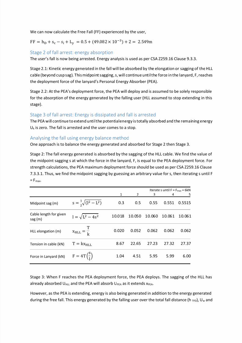
Stage 2: The fall energy generated is absorbed by the sagging of the HLL cable. We find the value of
the midpoint sagging s at which the force in the lanyard, F, is equal to the PEA deployment force. For
strength calculations, the PEA maximum deployment force should be used as per CSA Z259.16 Clause
7.3.3.1. Thus, we find the midpoint sagging by guessing an arbitrary value for s, then iterating s until F
= Fmax.
Iterate s until F = Fmax = 6kN
1 2 3 4 5
Midpoint sag (m) s = (l − L) 0.3 0.5 0.55 0.551 0.5515
Cable length for given
sag (m) l = L − 4s 10.018 10.050 10.060 10.061 10.061
HLL elongation (m) x =T
k 0.020 0.052 0.062 0.062 0.062
Tension in cable (kN) T = kx 8.67 22.65 27.23 27.32 27.37
Force in Lanyard (kN) F = 4Ts
l 1.04 4.51 5.95 5.99 6.00
Stage 3: When F reaches the PEA deployment force, the PEA deploys. The sagging of the HLL has
already absorbed UHLL and the PEA will absorb UPEA as it extends xPEA.
However, as the PEA is extending, energy is also being generated in addition to the energy generated
during the free fall. This energy generated by the falling user over the total fall distance (h TFD), Uw and

7/24/2019 HLL Basic Calculation
http://slidepdf.com/reader/full/hll-basic-calculation 6/10
the initial energy stored in the HLL at cusp sag, U HLLo has to be completely absorbed for the user to
come to a stop.
To analyse this, we start with an arbitrary value for xPEA then iterate xPEA until the remaining fall energy
Uk = 0. Before we do that, we have to calculate the following parameters.
HLL Rope Modulus kHLL =AE
l =(78.55 × 10)(55.8 × 10)
9.998200715= 438.388kN/m
Energy Stored in
HLL at cusp sag UHLLo =
k s =1
2(438.388)(49.082155 × 10⁻³) = 0.00kN-m
Energy absorbed
by HLL elongation UHLL =
k x =1
2(438.388)(0.054) = 0.64 kN-m
For clearance calculations, the PEA average deployment force, Favg should now be used instead as per
CSA Z259.16 Clause 7.3.3.2.
Iterate xPEA until Uk = 0
1 2 3 4
PEA extension (m) x 0.3 0.6 0.55 0.56
Total Fall Distance (m) h = FF − s + s + x 3.352 3.652 3.602 3.612
Energy generated by
falling user (kN-m) U
= Wh
3.29 3.58 3.53 3.54
Energy absorbed by PEA
extension (kN-m)U = Fx = Fx 1.44 2.88 2.64 2.69
Remaining energy (kN-m) U = U + U − U − U 0.99 -0.15 0.04 0.0
The fall energy has been fully absorbed by the HLL and PEA and the fall is now been completely
arrested. (Note: A situation can arise when there is fall energy remaining even after the PEA has
extended to its maximum length i.e. the capacity of the PEA is exceeded and the PEA has “bottomed-
out”.)
Results of Analysis
Workplace Safety and Health (Work At Heights) Regulation 11(2)(b) requires the fall arrest system to
have “enough fall clearance available to prevent the user from hitting an object, the ground or other
surfaces”.
This fall clearance includes the harness and D-ring slide during the fall, xw and a clearance margin (also
known as safety distance), E. We will assume xw to be 0.3m for a harness using normal webbing.
The clearance margin (as per CSA Z259.16 8.2.6.2),
E= 0.6 + 0.1(s − s) = 0.6 + 0.1(0.5515 − 49.082155 × 10⁻³) = 0.650m
7/24/2019 HLL Basic Calculation
http://slidepdf.com/reader/full/hll-basic-calculation 7/10
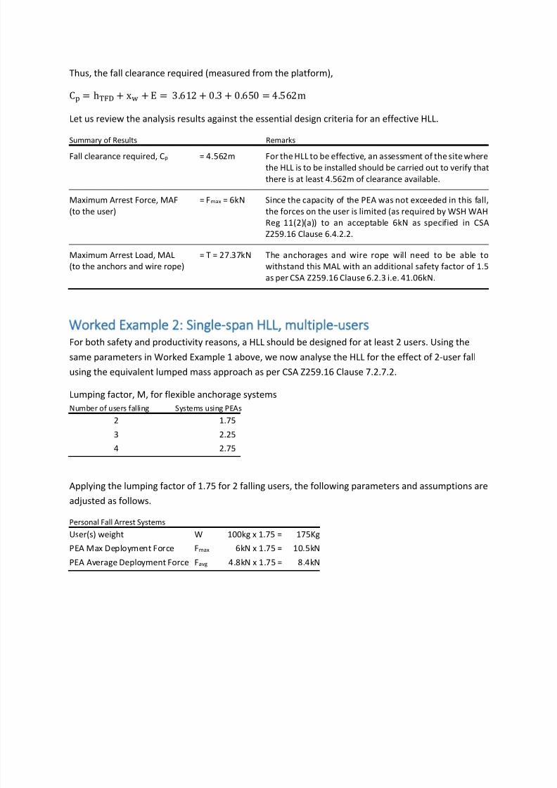
Thus, the fall clearance required (measured from the platform),
C = h + x + E = 3.612 + 0.3 + 0.650 = 4.562m
Let us review the analysis results against the essential design criteria for an effective HLL.
Summary of Results Remarks
Fall clearance required, Cp = 4.562m For the HLL to be effective, an assessment of the site where
the HLL is to be installed should be carried out to verify that
there is at least 4.562m of clearance available.
Maximum Arrest Force, MAF
(to the user)
= Fmax = 6kN Since the capacity of the PEA was not exceeded in this fall,
the forces on the user is limited (as required by WSH WAH
Reg 11(2)(a)) to an acceptable 6kN as specified in CSA
Z259.16 Clause 6.4.2.2.
Maximum Arrest Load, MAL
(to the anchors and wire rope)
= T = 27.37kN The anchorages and wire rope will need to be able to
withstand this MAL with an additional safety factor of 1.5
as per CSA Z259.16 Clause 6.2.3 i.e. 41.06kN.
Worked Example 2: Single span HLL multiple users
For both safety and productivity reasons, a HLL should be designed for at least 2 users. Using the
same parameters in Worked Example 1 above, we now analyse the HLL for the effect of 2-user fall
using the equivalent lumped mass approach as per CSA Z259.16 Clause 7.2.7.2.
Lumping factor, M, for flexible anchorage systems
Number of users falling Systems using PEAs
2 1.75
3 2.25
4 2.75
Applying the lumping factor of 1.75 for 2 falling users, the following parameters and assumptions are
adjusted as follows.
Personal Fall Arrest Systems
User(s) weight W 100kg x 1.75 = 175Kg
PEA Max Deployment Force Fmax 6kN x 1.75 = 10.5kNPEA Average Deployment Force Favg 4.8kN x 1.75 = 8.4kN

7/24/2019 HLL Basic Calculation
http://slidepdf.com/reader/full/hll-basic-calculation 8/10
We now use the above adjusted values to analyse for a 2-users fall. We iterate s until F = adjusted Fmax
of 10.5kN
Iterate s until F = Fmax = 10.5kN
1 2 3 4 5 6
Midpoint sag (m) s = (l − L) 0.5 0.8 0.6 0.66 0.667 0.6675
Cable length for given
sag (m) l = L − 4s 10.05 10.127 10.072 10.087 10.089 10.089
HLL elongation (m) x =T
k 0.052 0.129 0.074 0.089 0.090 0.091
Tension in cable (kN) T = kx 22.65 56.54 32.24 38.81 39.62 39.68
Force in Lanyard (kN) F = 4T
s
l
4.51 17.87 7.68 10.16 10.48 10.50
Again, we now iterate for xPEA until the fall energy is totally absorbed i.e. Uk = 0.
Iterate xPEA until Uk = 0
1 2 3
PEA extension (m) x 0.5 0.55 0.545
Total Fall Distance (m) h = FF − s + s + x 3.668 3.718 3.713
Energy generated by
falling user (kN-m) U = Wh 6.30 6.38 6.37
Energy absorbed by PEA
extension (kN-m)U = Fx = Fx 4.20 4.62 4.58
Remaining energy (kN-m) U = U + U − U − U 0.30 -0.03 0.00
The adjusted clearance margin is now
E = 0.6 + 0.1(0.6675 − 49.082155 × 10⁻³) = 0.662m
The clearance for the equivalent lumped mass
C = h + x + E = 3.713 + 0.3 + 0.662 = 4.675m
The clearance required for the last user to fall (as per CSA Z259.16 Clause 8.2.7)
C = 1.6C − 0.6C = (1.6 × 4.675) − (0.6 × 4.562) = 4.743m
Using the same methodology as above and applying different lumping factors, 3 and 4-user falls can
also be analysed. The results are summarized as follows.

7/24/2019 HLL Basic Calculation
http://slidepdf.com/reader/full/hll-basic-calculation 9/10
Comparison of Results 1-user 2-users 3-users 4-users
Free fall experienced by user (m) 2.549
Maximum Arrest Force, MAF (kN)
(experienced by the user)
6
Fall clearance required, Cp (m) 4.562 4.743 4.834 4.913
Maximum Arrest Load, MAL (kN)
(to the anchors and wire rope)
27.37 39.68 46.90 53.62
Minimum tensile strength required
for anchorages and wire rope (kN)
41.06 59.52 70.35 80.43
Other scenarios for consideration
The above two examples are simplified to illustrate the fundamental design parameters. HLLs
deployed in the real world can be more complicated requiring sophisticated analysis. Such real-world
HLL scenarios can include:
Energy absorbers incorporated in-line with the HLL where balance sag analysis will apply.
Multiple-span HLLs where the slack from the other spans will be pulled into the span where
the user fell before the HLL begins to tension up, affecting the cusp sag. The rope modulus will
also decrease with the longer length of wire rope used.
Pre-tension forces in the HLL changing due to temperature effects.
HLLs are anchored to flexible end anchorages instead of rigid end anchorages.
Conclusion
HLLs are commonly used to protect workers and minimize injuries to users in a fall. However, strength
requirements were often grossly underestimated and critical safety factors were neglected due to
common design mistakes.
A properly designed HLL needs to minimize injury to the user and to comply with the relevant legal
requirements. Thus the design criterion need to consider the Maximum Arrest Force (MAF) to the user,
the Maximum Arrest Load (MAL) to the anchors and the clearance height required.
This article demonstrated using energy balance approach to evaluate the above-mentioned design
criterion for a single-span HLL system based on the design code CSA Z259.16. A 1-user fall was first
analysed followed by a 2-user fall.
It is hoped that this article can raise awareness of the various parameters that designers should take
into consideration in their design and evaluation of horizontal lifeline systems.
Acknowledgement
The authors have attended the Qualified Fall Protection Engineer course by Engineer Greg Small and
his co-trainers in North America. The calculations described herein are based on an Excel template
created by Er. Small.

7/24/2019 HLL Basic Calculation
http://slidepdf.com/reader/full/hll-basic-calculation 10/10
References
Ministry of Manpower (2013) Occupational Safety and Health Division Annual Report 2012
http://mom.gov.sg/Documents/safety-health/reports-stats/OSHD-
AR2012/OSHD_AR2012_part1.pdf
Canadian Standards Association (2004) Z259.16-04 Design of Active Fall-Protection Systems Ontario:Canadian Standards Association
Goh, Y.M., 2014. An Empirical Investigation of the Average Deployment Force of Personal Fall Arrest
Energy Absorbers. J. Constr. Eng. and Manage. - Am. Soc. of Civ. Eng. (published online).
Hoe, Y. P., Goh, Y. M., Sim, S. Y. (2012) Design of Fall Arrest Systems: A Review of the Current Issues in
the Singapore Construction Industry. “CIB W099 International Conference on Modelling and
Building Health and Safety” 10-11 September 2012, Singapore
Wang, Q., Hoe, Y. P., Goh, Y. M. (2014) Evaluating the Inadequacies in Horizontal Lifeline Designs: Case
Studies in Singapore. “CIB W099 International Conference on Achieving Sustainable
Construction Health and Safety”, 2-3 June 2014, Lund, Sweden
Related Documents