深圳市海凌科电子有限公司 Shenzhen Hi-Link Electronic Co.,Ltd Http://www.hlktech.com Tel:0755-83575155 Fax:0755-83575189 1 Shenzhen Hi-Link ElectronicTechnology co., Ltd HLK-RM04 User Manual ETHERNET WIFI Full Function Serial Network/Wireless Module 1 BRIEF INTRODUCTION .................................................................................................................................... 5 2 SUMMARIZE....................................................................................................................................................... 5

Welcome message from author
This document is posted to help you gain knowledge. Please leave a comment to let me know what you think about it! Share it to your friends and learn new things together.
Transcript

深圳市海凌科电子有限公司 Shenzhen Hi-Link Electronic Co.,Ltd Http://www.hlktech.com Tel:0755-83575155 Fax:0755-83575189
1
Shenzhen Hi-Link ElectronicTechnology co., Ltd
HLK-RM04 User Manual
ETHERNET
WIFI
Full Function Serial Network/Wireless Module
1 BRIEF INTRODUCTION....................................................................................................................................5
2 SUMMARIZE.......................................................................................................................................................5

深圳市海凌科电子有限公司 Shenzhen Hi-Link Electronic Co.,Ltd Http://www.hlktech.com Tel:0755-83575155 Fax:0755-83575189
2
2.1 TECHNICAL SPECIFICATIONS ............................................................................................................................5
2.2 HARDWARE EXPLANATION ..............................................................................................................................6
2.2.1 Mechanical Dimensions ........................................................................................................................6
3 QUICK START.....................................................................................................................................................8
3.1 RESTORE FACTORY SETTINGS ...........................................................................................................................8
3.2 CONFIGURATE NETWORK PARAMETER ..............................................................................................................8
3.3 CONFIGURATE SERIAL NETWORK PARAMETER...................................................................................................9
4 FUNCTION DESCRIPTION ...............................................................................................................................9
4.1 SERIAL TO ETHERNET ......................................................................................................................................9
4.2 SERIAL TO WIFI CLIENT..............................................................................................................................10
4.3 SERIAL TO WIFI AP ......................................................................................................................................10
4.4 DEFAULT MODE .............................................................................................................................................11
4.5 PARAMETER CONFIGURATION DIRECTION............................................................................................11
5 WEB CONFIGURATION ..................................................................................................................................12
5.1 WEB NETWORK CONFIGURATION...................................................................................................................12
5.1.1 Serial to Ethernet-dynamic ip ..............................................................................................................13
5.1.2 Serial to Ethernet-static ip...................................................................................................................13
5.1.3 Serial to WIFI CLIENT-dynamic ip......................................................................................................13
5.1.4 Serial to WIFI CLIENT-static ip...........................................................................................................14
5.1.5 Serial to WIFI AP................................................................................................................................14
5.2 WEB SERIAL CONFIGURATION .......................................................................................................................14
6 SERIAL AT COMMAND CONFIGURATION..................................................................................................16
6.1 ACCESS TO AT COMMAND MODE ....................................................................................................................16
6.2 AT COMMAND ..............................................................................................................................................16
6.2.1 Net mode.............................................................................................................................................17
6.2.2 wifi_conf .............................................................................................................................................18
6.2.3 dhcpc ..................................................................................................................................................18
6.2.4 net_ip..................................................................................................................................................19
6.2.5 net_dns ...............................................................................................................................................19
6.2.6 dhcpd..................................................................................................................................................19
6.2.7 dhcpd_ip .............................................................................................................................................20
6.2.8 dhcpd_dns...........................................................................................................................................20

深圳市海凌科电子有限公司 Shenzhen Hi-Link Electronic Co.,Ltd Http://www.hlktech.com Tel:0755-83575155 Fax:0755-83575189
3
6.2.9 dhcpd_time..........................................................................................................................................20
6.2.10 net_commit..........................................................................................................................................20
6.2.11 out_trans.............................................................................................................................................21
6.2.12 remoteip..............................................................................................................................................21
6.2.13 remoteport ..........................................................................................................................................21
6.2.14 remotepro............................................................................................................................................22
6.2.15 timeout................................................................................................................................................22
6.2.16 mode...................................................................................................................................................22
6.2.17 uart.....................................................................................................................................................23
6.2.18 uartpacklen .........................................................................................................................................23
6.2.19 uartpacktimeout ..................................................................................................................................23
6.2.20 save ....................................................................................................................................................23
6.2.21 reconn.................................................................................................................................................24
6.2.22 ver ......................................................................................................................................................24
6.3 AT COMMAND CONTROL CODE ROUTION ........................................................................................................24
6.3.1 Inquiry configuration information........................................................................................................24
6.3.2 Serial to Ethernet(Dynamic ip address)................................................................................................25
6.3.3 Serial to Ethernet(static ip address) .....................................................................................................26
6.3.4 Serial to wifi client(dynamic IP address)..............................................................................................27
6.3.5 Serial to wifi client(static IP address) ..................................................................................................28
6.3.6 Serial to wifi AP ..................................................................................................................................29
6.3.7 Restore factory value...........................................................................................................................30
7 SERIAL CONFIGURATION TOOLS ...............................................................................................................30
7.1 SEARCHING THE MODULE..............................................................................................................................32
7.2 SET EACH PARAMETERS.................................................................................................................................32
7.3 SUBMIT THE CONFIGURATION.........................................................................................................................33
7.4 USER DATA RETENTION .................................................................................................................................34
7.5 INQUIRY CONFIGURATION ..............................................................................................................................34
7.6 ACCESS TO TRANSPARENT TRANSMISSION MODE.............................................................................................34
7.7 RESTORE FACTORY FACTORY VALUE SETTING..................................................................................................34
8 DEVICE SEARCH TOOLS..................................................................................................................................35
9 RESTORE FACTORY SETTINGS ...................................................................................................................36
10 FIRMWARE UPGRADE....................................................................................................................................37

深圳市海凌科电子有限公司 Shenzhen Hi-Link Electronic Co.,Ltd Http://www.hlktech.com Tel:0755-83575155 Fax:0755-83575189
4
APPENDIX A DOCUMENT REVISION RECORD...............................................................................................37

深圳市海凌科电子有限公司 Shenzhen Hi-Link Electronic Co.,Ltd Http://www.hlktech.com Tel:0755-83575155 Fax:0755-83575189
5
1 Brief Introduction
HLK-RM04 is a new low-cost embedded UART-ETH-WIFI module (serial port - Ethernet - Wireless network) developed by Shenzhen Hi-Link ElectronicTechnology co., Ltd
This product is an embedded module based on the universal serial interface network standard, built-in TCP / IP protocol stack, enabling the user serial port, Ethernet, wireless network (wifi) interface between the conversions.
Through the HLK-RM04 module, the traditional serial devices do not need to change any configuration; data can be transmitted through the Internet network. Provide a quick solution for the user’s serial devices to transfer data via Ethernet.
Picture1.F-structure
2 Summarize
2.1 Technical Specifications
Table2-1Technical Specifications wireless:IEEE 802.11n、IEEE 802.11g、IEEE 802.11b
Network standard wired:IEEE 802.3、IEEE 802.3u
Wireless transmission rate
11n: maximum up to 150Mbps
11g: maximum up to 54Mbps
11b: maximum up to 11Mbps
Tracks number 1-14
Frequency range 2.4-2.4835G
Emission power 12-15DBM
Interface 1个 10/100Mbps LAN/WAN multiplex interface、interface
Antenna
Antenna type Onboard antenna / External Antenna
Ethernet WIFI(Client/AP)
Serial Com

深圳市海凌科电子有限公司 Shenzhen Hi-Link Electronic Co.,Ltd Http://www.hlktech.com Tel:0755-83575155 Fax:0755-83575189
6
Functional Parameters
WIFI work mode Client/AP/Router
WDS Function Support WDS wireless bridge connection
Wireless MAC address filtering
Wireless security function switch 64/128/152 bit WEP encryption
Wireless security
WPA-PSK/WPA2-PSK、WPA/WPA2 security mechanism
Remote Web management
Configuration file import and export Network management
WEB software upgrade
Serial to Ethernet
Maximum transmission
rate 230400bps
TCP connection Max connection number>20
UDP connection Max connection number>20
Serial baud rate 50~230400bps
Other Parameters
Status indicator Status indicator
Operating temperature:-20-70℃
Operating humidity:10%-90%RH(noncondensing)
Storage temperature:-40-80℃ Environmental standard
Storage humidity:5%-90%RH(noncondensing)
Additional properties Frequency bandwidth optional:20MHz、40MHz,Automatic
2.2 Hardware Explanation
2.2.1 Mechanical Dimensions
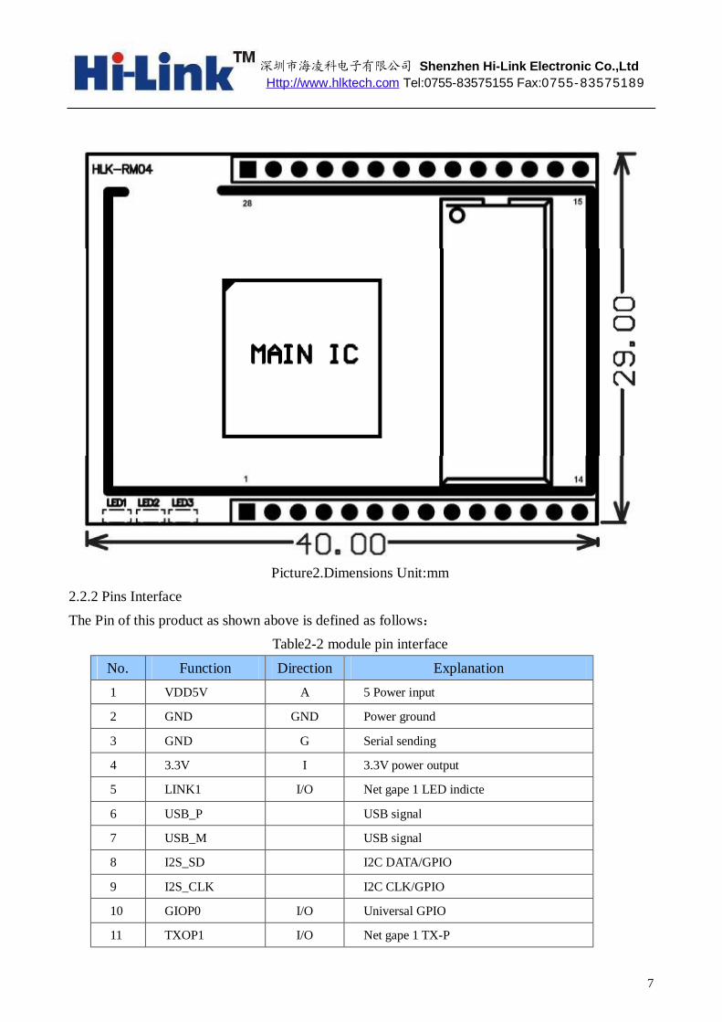
HLK-RM04 Mechanical Dimensions is shown in the following picture:
深圳市海凌科电子有限公司 Shenzhen Hi-Link Electronic Co.,Ltd Http://www.hlktech.com Tel:0755-83575155 Fax:0755-83575189
7
Picture2.Dimensions Unit:mm
2.2.2 Pins Interface The Pin of this product as shown above is defined as follows:
Table2-2 module pin interface
No. Function Direction Explanation 1 VDD5V A 5 Power input
2 GND GND Power ground
3 GND G Serial sending
4 3.3V I 3.3V power output
5 LINK1 I/O Net gape 1 LED indicte
6 USB_P USB signal
7 USB_M USB signal
8 I2S_SD I2C DATA/GPIO
9 I2S_CLK I2C CLK/GPIO
10 GIOP0 I/O Universal GPIO
11 TXOP1 I/O Net gape 1 TX-P

深圳市海凌科电子有限公司 Shenzhen Hi-Link Electronic Co.,Ltd Http://www.hlktech.com Tel:0755-83575155 Fax:0755-83575189
8
12 TXON1 I/O Net gape 1 TX-N
13 RXIP2 I/O Net gape 2 RX-P
14 RXIN2 I/O Net gape 2 RX-N
15 RXIN1 I/O Net gape 1 RX-P
16 RXIP1 I/O Net gape 1 RX-P
17 TXON2 I/O Net gape 2 TX-N
18 TXOP2 I/O Net gape 2 TX-P
19 RTS_N I All function serial RTS
20 UART_RX I Simple serial RX
21 UART_TX O Simple serial TX
22 RXD I All function serial RX
23 LINK2 I/O Net gape 2 LED I/O indicte
24 CTS_N O All function serial CTS
25 RIN I GPIO
26 TXD O All function serial TX
27 1.8V Power Out Net gape 1.8V output
28 VDD5V Power In 5V input
3 Quick Start
3.1 Restore factory settings
In order to ensure that all of configuration process is correct, bringing the module to restore the factory settings firstly. Factory mode, the module can skip this step. Above 5V (500mA) to power the module on the power, wait about 2.5 minutes for the system to start, after the start completion, pulled ES / RST pin down and make it surpass Trst, release ES / RST pin, the system will automatically restart. After rebooting, the system is already in Factory mode.
3.2 Configurate network parameter
Set the PC to static IP mode and then connect it with the module via Ethernet or wifi. The IP address is set to 192.168.16.100/255.255.255.0, gateway 192.168.16.254. The (wifi default ssid and the default password, see this document.) open the browser http://192.168.16.254, enter the web configuration page, default user name and password is admin / admin. Modify the network parameters through the web. Now, the module’s IP address is 192.168.16.254. Configuration details can be seen in 5.1.

深圳市海凌科电子有限公司 Shenzhen Hi-Link Electronic Co.,Ltd Http://www.hlktech.com Tel:0755-83575155 Fax:0755-83575189
9
3.3 Configurate serial network parameter
Opens the browser http://192.168.16.254/ser2net.asp, enter the serial-to-network web configuration page. Configure the serial-to-network parameters as needed through a web page. Configuration details can be seen in 5.2.
4 Function Description
The module can be divided into four major modes:default mode,serial to Ethernet,serial to WIFI CLIENT and serial to WIFI AP.
4.1 Serial to Ethernet
Chart3.serial to Ethernet model
In this mode, ETH1 enable, WIFI, ETH2 function close. Through the appropriate settings, the
data between COM1 and ETH1 network can achieve mutual conversion. Ethernet can be configured as dynamic IP address (DHCP), can also be configured as static IP
address (STATIC).
DHCP IP /STATIC IP
ETHERNET SERIAL
HLK-RM04 MCU SWITCH
/ROUTER COM1 ETH1

深圳市海凌科电子有限公司 Shenzhen Hi-Link Electronic Co.,Ltd Http://www.hlktech.com Tel:0755-83575155 Fax:0755-83575189
10
4.2 Serial to WIFI CLIENT
Chart 4.Serial to WIFI CLIENT model
In this mode, WIFI enable, module works in the client mode, ETH1, ETH2 function close.
Through the appropriate settings, the data between COM1 and WIFI network can achieve mutual conversion.
WIFI CLIENT can be configured as dynamic IP address (DHCP), can also be configured as static IP address (STATIC).
WIFI safety: support all encryption methods at present.
4.3 Serial to WIFI AP
Chart 5. Serial to WIFI AP model
In this mode, WIFI enable, module works in the AP mode, ETH1, ETH2 function close.
DHCP ENABLE
SERIAL
HLK-RM04 MCU WIFI CLIENT
(PHONE、pad)
COM1 WIFI AP
DHCP IP /STATIC IP
SERIAL
HLK-RM04 MCU WIFI AP
COM1WIFI Client

深圳市海凌科电子有限公司 Shenzhen Hi-Link Electronic Co.,Ltd Http://www.hlktech.com Tel:0755-83575155 Fax:0755-83575189
11
Through the appropriate settings, the data between COM1 and WIFI network can achieve mutual conversion.
WIFI safety: support all encryption methods at present. In this mode, WIFI device can connect with the module and become the device under WIFI
LAN.
4.4 Default mode
Chart 6.Default mode model
In this mode, WIFI enable, module works in the AP mode, ETH1, ETH2 function enable.
ETH1 works as WAN, ETH2 works as LAN. Through the appropriate settings, the data between COM1 and network can achieve mutual conversion.
WIFI safety: support all encryption methods at present. In this mode, WIFI device can connect with the module and become the device under WIFI
LAN. WAN default IP is dynamic IP address. LAN, WIFI for the same local area network, enabled by
default DHCP server.
4.5 Parameter configuration direction
The module provides two ways for the configuration parameters: 1.Web page; 2. Serial AT command.
Access to WEB configuration page requires the confirmation of the module’s IP addresses, as well as the user name and password that authenticated by WEB. Configurating parameters through the serial port AT command needs to make the module into the AT command mode first.
DHCP ENABLE
SERIAL
HLK-RM04 MCU WIFI CLIENT
(PHONE、pad)
COM1WIFI AP
ETH2
ETH1
LAN
WAN

深圳市海凌科电子有限公司 Shenzhen Hi-Link Electronic Co.,Ltd Http://www.hlktech.com Tel:0755-83575155 Fax:0755-83575189
12
Serial configuration tool HLK-RM04_CONFIG: Configurate the module through AT command,provide a easier and convenient configuration process through the configuration combination of each parameter.
5 WEB configuration
Chart 7.WEB configuration page
Through the correct module address (default address:http://192.168.16.254/ser2net.asp),you can access to the WEB configuration page.
The page can be divided into 3 areas: 1 Network configuration area 2 Serial function configuration areas 3 Configuration submit area
5.1 WEB network configuration
Net mode selection: Default – default work mode ETH-SERIAL – Serial to Ethernet WIFI (CLIENT)-SERIAL – serial to WIFI CLIENT WIFI (AP)-SERIAL) – Serial to WIFI AP
Choose different work mode,the web will show you different page.Mode configuration page

深圳市海凌科电子有限公司 Shenzhen Hi-Link Electronic Co.,Ltd Http://www.hlktech.com Tel:0755-83575155 Fax:0755-83575189
13
is as follows: 5.1.1 Serial to Ethernet-dynamic ip
Chart 8. Serial to Ethernet-dynamic
5.1.2 Serial to Ethernet-static ip
Chart 9. Serial to Ethernet-static
5.1.3 Serial to WIFI CLIENT-dynamic ip
Chart 10. serial to WIFI CLIENT dynamic

深圳市海凌科电子有限公司 Shenzhen Hi-Link Electronic Co.,Ltd Http://www.hlktech.com Tel:0755-83575155 Fax:0755-83575189
14
5.1.4 Serial to WIFI CLIENT-static ip
Chart 11. Serial to WIFI CLIENT-static
5.1.5 Serial to WIFI AP
Chart12. Serial to WIFI AP
5.2 WEB serial configuration
Serial Web configuration page(ser2net.asp)is as follows:

深圳市海凌科电子有限公司 Shenzhen Hi-Link Electronic Co.,Ltd Http://www.hlktech.com Tel:0755-83575155 Fax:0755-83575189
15
Current shows the current configuration ,Updated shows the current revision parameters。Submit submit the revision. Serial Configure:Serial configuration.fomat:Baud rate, data bits, parity bit, stop bit. For example:“115200,8,n,1”. Serial Framing Lenth:The Lenth of Serial Framing
Serial Framing Timeout:The time of Serial Framing Network Mode:choose Client、Server or none。
Remote Server Domain/IP:Remote Server Domain/IP address For exmpale:192.168.11.245 or www.hlktech.com . Locale/Remote Port Number:The specified parameter is not the same under the different network modes. Client specifies the port number on the remote, Server specified local port number.
深圳市海凌科电子有限公司 Shenzhen Hi-Link Electronic Co.,Ltd Http://www.hlktech.com Tel:0755-83575155 Fax:0755-83575189
16
Network Protocol:Use tcp or udp Protocol Network Timeout:Under the server network mode, no data transmission within the timeout period, the connection will be disconnected. 0 specifies never disconnected.
6 Serial AT command configuration
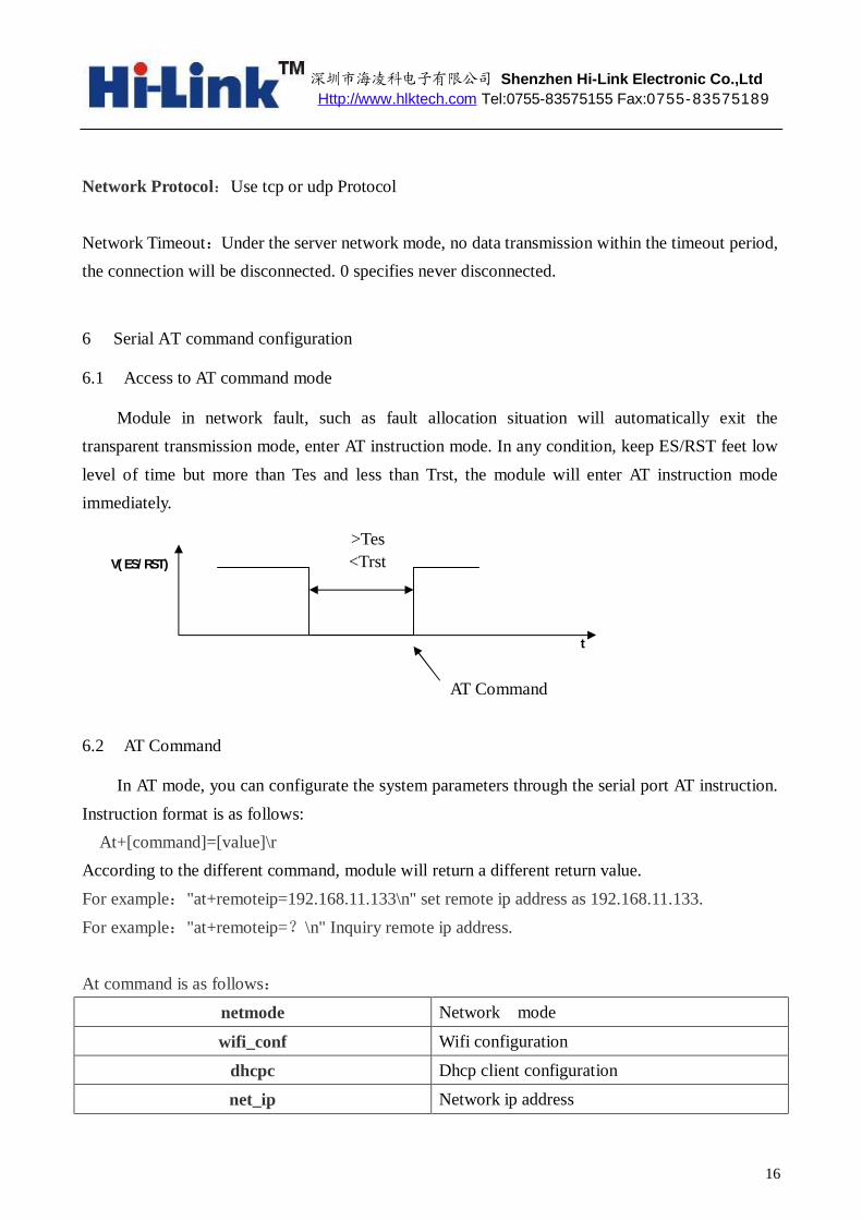
6.1 Access to AT command mode
Module in network fault, such as fault allocation situation will automatically exit the transparent transmission mode, enter AT instruction mode. In any condition, keep ES/RST feet low level of time but more than Tes and less than Trst, the module will enter AT instruction mode immediately.
6.2 AT Command
In AT mode, you can configurate the system parameters through the serial port AT instruction. Instruction format is as follows: At+[command]=[value]\r According to the different command, module will return a different return value. For example:"at+remoteip=192.168.11.133\n" set remote ip address as 192.168.11.133. For example:"at+remoteip=?\n" Inquiry remote ip address. At command is as follows:
netmode Network mode
wifi_conf Wifi configuration
dhcpc Dhcp client configuration
net_ip Network ip address
>Tes <Trst
t
AT Command .
V(ES/RST)

深圳市海凌科电子有限公司 Shenzhen Hi-Link Electronic Co.,Ltd Http://www.hlktech.com Tel:0755-83575155 Fax:0755-83575189
17
net_dns Network dns address
dhcpd Dhcp server configuration
dhcpd_ip Dhcp server ip address
dhcpd_dns Dhcp server dns address
dhcpd_time Dhcp sever time allocation
net_commit Submit network configuration
out_trans Exit transparent transmission mode
remoteip Remote server domain name or IP address
remoteport The local or distal port number
remotepro Network Protocol type
timeout Network timeout
mode Network mode
uart Serial port configuration
uartpacklen Serial group frame length
uartpacktimeout Serial framing time
save Save the configuration and start service
reconn Restart services
default Restore factory value settings
reboot Restart the module
ver The version of module
6.2.1 Net mode
Function: Network mode setting Format:
At+netmode=<netmode>\r
Parameters: Table 6-3 network mode
value meaning
0 Default setup
1 Ethernet
2 Wifi client
3 Wifi ap

深圳市海凌科电子有限公司 Shenzhen Hi-Link Electronic Co.,Ltd Http://www.hlktech.com Tel:0755-83575155 Fax:0755-83575189
18
6.2.2 wifi_conf Function: Wireless parameter setting Format:
At+wifi_conf=<ssid>,<encrypt type>, <password> \r Parameters:
ssid:Network SSID Encrypt type: Encryption mode
Table 6-4 Encryption mode
6.2.3 dhcpc
Function: Dhcp client enable Format:
At+dhcpc=<dhcpc>\r
Parameters: Table 6-5 Dhcp client enable
value meaning
0 Static ip address
1 Dynamic ip address
value meaning
none Open network
wep_open Wep encryption,open authentication method
wep Wep encryption,encryption authentication wpa_tkip wpa tkip
wpa_aes wpa aes
wpa2_tkip wpa2 tkip
wpa2_aes wpa2 aes
wpawpa2_tkip wpa/wpa2 tkip
wpawpa2_aes wpa/wpa2 aes

深圳市海凌科电子有限公司 Shenzhen Hi-Link Electronic Co.,Ltd Http://www.hlktech.com Tel:0755-83575155 Fax:0755-83575189
19
6.2.4 net_ip Function: Network mode setting
This parameter is not valid when Dhcp client feature is turned on. Format:
At+Net_ip=<ip>,<mask>,<gateway>\r Parameters:
Ip:Ip address Mask:Subnet mask Gateway:Gateway Network Element
6.2.5 net_dns Function: Network mode setting
This parameter is not valid when Dhcp client feature is turned on
Format: At+Net_dns=<dns1>,<dns2>\r
parameters: dns1:Major DNS address dns2:Minor DNS address
6.2.6 dhcpd Function:
Dhcp server enable This parameter is not valid when the network mode is AP.
Format: At+dhcpd=<dhpcd>\r
Parameters: Table 6-6 Dhcp servers enable
value meaning
0 close
1 open

深圳市海凌科电子有限公司 Shenzhen Hi-Link Electronic Co.,Ltd Http://www.hlktech.com Tel:0755-83575155 Fax:0755-83575189
20
6.2.7 dhcpd_ip Function: Dhcp server IP setting Format:
At+Dhcpd_ip=<ip start>,<ip end>,<mask>,<gateway>\r parameters:
Ip start:Ip started address Ip end:Ip ended address Mask:Subnet mask Gateway:Gateway Network Element
6.2.8 dhcpd_dns
Function: Dhcp server dns setting Format:
At+Dhcpd_dns=<dns1>,<dns2>\r Parameters:
dns1:Major dns address dns2:Minor dns address
6.2.9 dhcpd_time Function: Dhcp server time setting Format:
At+Dhcpd_time=<time >\r Parameters: time: Dhcp effective time assigned to device.
6.2.10 net_commit Function: Submit to network setting Network configuration parameters set to be submitted by this parameter to save the entry into force.

深圳市海凌科电子有限公司 Shenzhen Hi-Link Electronic Co.,Ltd Http://www.hlktech.com Tel:0755-83575155 Fax:0755-83575189
21
Format: At+ Net_commit=< Net_commit >\r
Parameters: Table 6-7 submit to network setting
value meaning
0 invalid
1 submit
6.2.11 out_trans Function: Exit the transparent transmission mode Format:
At+out_trans=<out_trans>\r Parameters:
Table 6-8 Exit the transparent transmission mode
value meaning
Arbitrarily Exit the transparent transmission mode
6.2.12 remoteip Function: Remote ip or domain name setting
Format: At+remoteip=< remoteip >\r
Parameters: Remote server domain name or IP address
6.2.13 remoteport Function: Remote port setting
Format: At+ remoteport=<remoteport>\r Parameters:
Remoteport:Remote port

深圳市海凌科电子有限公司 Shenzhen Hi-Link Electronic Co.,Ltd Http://www.hlktech.com Tel:0755-83575155 Fax:0755-83575189
22
6.2.14 remotepro Function: Protocol Type setting Format: At+ remotepro=<remotepro>\r Parameters:
Table 6-9 remotepro parameters setting value meaning
None No protocol
Tcp Tcp protocol
Udp Udp protocol
6.2.15 timeout Function Network time-out
Format: At+timeout=<timeout>\r Parameters:
Network time-out server Network mode, when there is not any data transfer during the time-out, the connection will be disconnected. 0 specifies never disconnected. 6.2.16 mode
Function: The conversion mode setting Format: At+mode=<mode>\r Parameters:
Table 6-10 mode setting value meaning
None No protocol
Client Tcp protocol
Server Udp protocol

深圳市海凌科电子有限公司 Shenzhen Hi-Link Electronic Co.,Ltd Http://www.hlktech.com Tel:0755-83575155 Fax:0755-83575189
23
6.2.17 uart Function: Serial configuration setting Format: At+uart=<baud>,<data>,<parity>,<stop>\r parameters:
Baud:Baud rate Data:Data bits Parity:Parity bit Stop:length of stop bit
6.2.18 uartpacklen
Function: Serial framing length setting Format: At+uartpacklen =<uartpacklen>\r Parameters:
uartpacklen:Serial framing length(Unit:bit).Default value: 64. 6.2.19 uartpacktimeout
Function: Serial framing time setting Format: At+ uartpacktimeout=<uartpacktimeout>\r Parameters:
uartpacktimeout:Serial framing time(unit:ms)。Default value:10 6.2.20 save
Function: Submitted to serial converter configuration and restart the service. Format: At+ save=<save>\r Parameters:
Table 6-11 submit to network setting
value meaning
深圳市海凌科电子有限公司 Shenzhen Hi-Link Electronic Co.,Ltd Http://www.hlktech.com Tel:0755-83575155 Fax:0755-83575189
24
0 invalid
1 submit
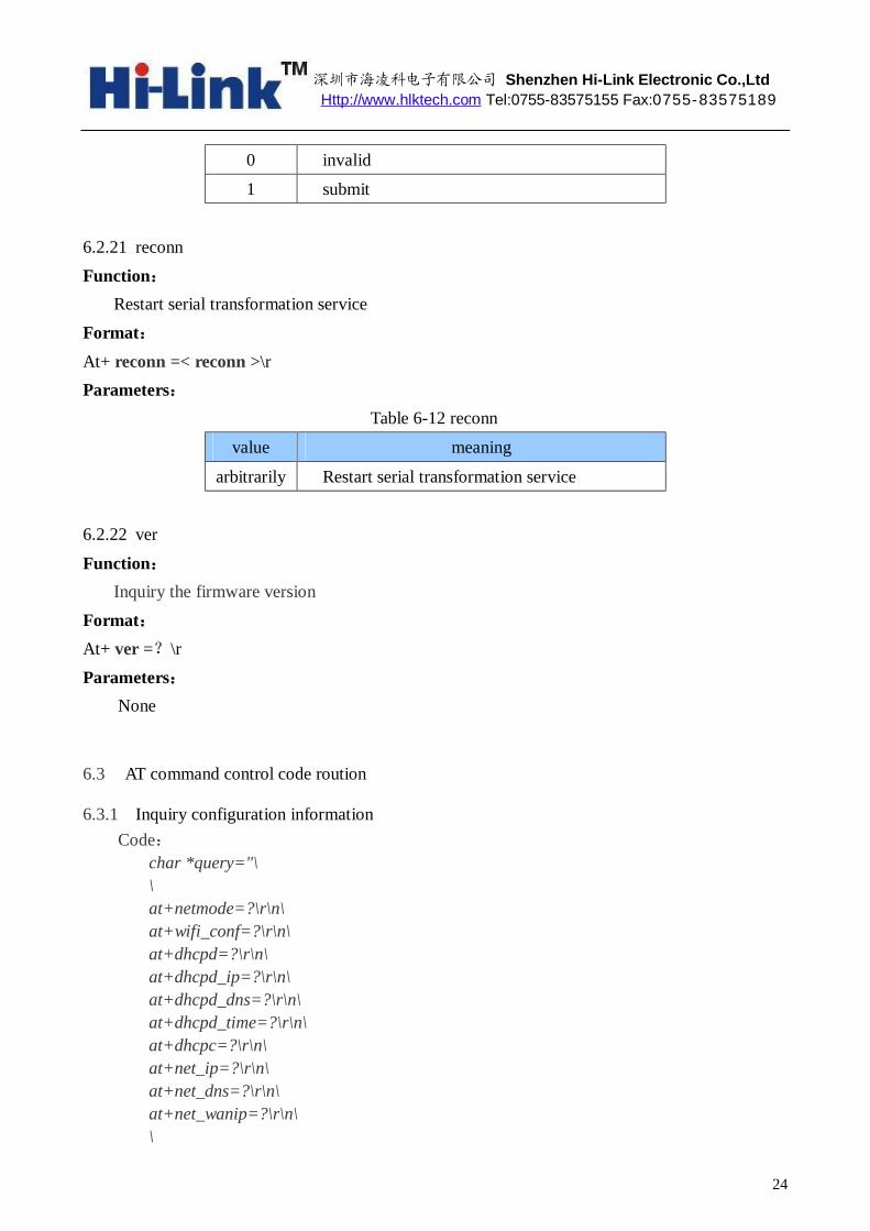
6.2.21 reconn Function: Restart serial transformation service Format: At+ reconn =< reconn >\r Parameters:
Table 6-12 reconn
value meaning
arbitrarily Restart serial transformation service
6.2.22 ver
Function: Inquiry the firmware version Format: At+ ver =?\r Parameters:
None
6.3 AT command control code roution
6.3.1 Inquiry configuration information Code:
char *query="\ \ at+netmode=?\r\n\ at+wifi_conf=?\r\n\ at+dhcpd=?\r\n\ at+dhcpd_ip=?\r\n\ at+dhcpd_dns=?\r\n\ at+dhcpd_time=?\r\n\ at+dhcpc=?\r\n\ at+net_ip=?\r\n\ at+net_dns=?\r\n\ at+net_wanip=?\r\n\ \

深圳市海凌科电子有限公司 Shenzhen Hi-Link Electronic Co.,Ltd Http://www.hlktech.com Tel:0755-83575155 Fax:0755-83575189
25
at+remoteip=?\r\n\ at+remoteport=?\r\n\ at+remotepro=?\r\n\ at+timeout=?\r\n\ at+mode=?\r\n\ at+uart=?\r\n\ at+uartpacklen=?\r\n\ at+uartpacktimeout=?\r\n\ at+ver=?\r\n\ ";
Com_send(query);
Run,return:
at+netmode=? 0
at+wifi_conf=? Hi-Link,wpa2_aes,12345678
at+dhcpd=? 0
at+dhcpd_ip=? 192.168.14.1,192.168.15.254,255.255.254.0,192.168.15.254
at+dhcpd_dns=? 192.168.15.254,0.0.0.0
at+dhcpd_time=? 86400
at+dhcpc=? 1
at+net_ip=? 192.168.15.254,255.255.254.0,192.168.11.1
at+net_dns=? 192.168.11.1,0.0.0.0
at+net_wanip=? ,,
at+remoteip=? 192.168.11.245
at+remoteport=? 8080
at+remotepro=? tcp
at+timeout=? 0
at+mode=? server
at+uart=? 115200,8,n,1
at+uartpacklen=? 64
at+uartpacktimeout=? 10
at+ver=? V1.39(Dec 6 2012)
6.3.2 Serial to Ethernet(Dynamic ip address)
Code: char *commands_eth="\ \ at+netmode=1\r\n\ at+dhcpc=1\r\n\ \ at+remoteip=192.168.11.245\r\n\ at+remoteport=8080\r\n\

深圳市海凌科电子有限公司 Shenzhen Hi-Link Electronic Co.,Ltd Http://www.hlktech.com Tel:0755-83575155 Fax:0755-83575189
26
at+remotepro=tcp\r\n\ at+timeout=0\r\n\ at+mode=server\r\n\ at+uart=115200,8,n,1\r\n\ at+uartpacklen=64\r\n\ at+uartpacktimeout=10\r\n\ at+net_commit=1\r\n\ at+reconn=1\r\n\ ";
Com_send(commands_eth);
Run and return:
at+netmode=1 ok
at+dhcpc=1
at+remoteip=192.168.11.245 ok
at+remoteport=8080 ok
at+remotepro=tcp
at+timeout=0 ok
at+mode=server
at+uart=115200,8,n,1 ok
at+uartpacklen=64 ok
at+uartpacktimeout=10 ok
at+net_commit=1
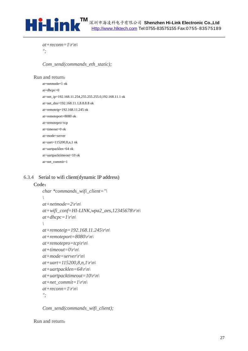
6.3.3 Serial to Ethernet(static ip address)
Code: char *commands_eth_static="\ \ at+netmode=1\r\n\ at+dhcpc=0\r\n\ at+net_ip=192.168.11.254,255.255.255.0,192.168.11.1\r\n\ at+net_dns=192.168.11.1,8.8.8.8\r\n\ \ at+remoteip=192.168.11.245\r\n\ at+remoteport=8080\r\n\ at+remotepro=tcp\r\n\ at+timeout=0\r\n\ at+mode=server\r\n\ at+uart=115200,8,n,1\r\n\ at+uartpacklen=64\r\n\ at+uartpacktimeout=10\r\n\ at+net_commit=1\r\n\
深圳市海凌科电子有限公司 Shenzhen Hi-Link Electronic Co.,Ltd Http://www.hlktech.com Tel:0755-83575155 Fax:0755-83575189
27
at+reconn=1\r\n\ ";
Com_send(commands_eth_static);
Run and return: at+netmode=1 ok
at+dhcpc=0
at+net_ip=192.168.11.254,255.255.255.0,192.168.11.1 ok
at+net_dns=192.168.11.1,8.8.8.8 ok
at+remoteip=192.168.11.245 ok
at+remoteport=8080 ok
at+remotepro=tcp
at+timeout=0 ok
at+mode=server
at+uart=115200,8,n,1 ok
at+uartpacklen=64 ok
at+uartpacktimeout=10 ok
at+net_commit=1
6.3.4 Serial to wifi client(dynamic IP address)
Code: char *commands_wifi_client="\ \ at+netmode=2\r\n\ at+wifi_conf=HI-LINK,wpa2_aes,12345678\r\n\ at+dhcpc=1\r\n\ \ at+remoteip=192.168.11.245\r\n\ at+remoteport=8080\r\n\ at+remotepro=tcp\r\n\ at+timeout=0\r\n\ at+mode=server\r\n\ at+uart=115200,8,n,1\r\n\ at+uartpacklen=64\r\n\ at+uartpacktimeout=10\r\n\ at+net_commit=1\r\n\ at+reconn=1\r\n\ ";
Com_send(commands_wifi_client);
Run and return:
深圳市海凌科电子有限公司 Shenzhen Hi-Link Electronic Co.,Ltd Http://www.hlktech.com Tel:0755-83575155 Fax:0755-83575189
28
at+netmode=2 ok
at+wifi_conf=HI-LINK,wpa2_aes,12345678 ok
at+dhcpc=1
at+remoteip=192.168.11.245 ok
at+remoteport=8080 ok
at+remotepro=tcp
at+timeout=0 ok
at+mode=server
at+uart=115200,8,n,1 ok
at+uartpacklen=64 ok
at+uartpacktimeout=10 ok
at+net_commit=1
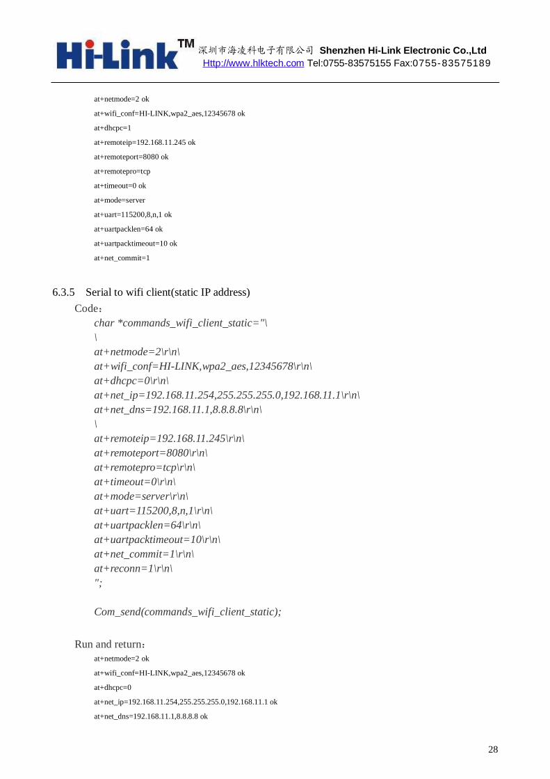
6.3.5 Serial to wifi client(static IP address)
Code: char *commands_wifi_client_static="\ \ at+netmode=2\r\n\ at+wifi_conf=HI-LINK,wpa2_aes,12345678\r\n\ at+dhcpc=0\r\n\ at+net_ip=192.168.11.254,255.255.255.0,192.168.11.1\r\n\ at+net_dns=192.168.11.1,8.8.8.8\r\n\ \ at+remoteip=192.168.11.245\r\n\ at+remoteport=8080\r\n\ at+remotepro=tcp\r\n\ at+timeout=0\r\n\ at+mode=server\r\n\ at+uart=115200,8,n,1\r\n\ at+uartpacklen=64\r\n\ at+uartpacktimeout=10\r\n\ at+net_commit=1\r\n\ at+reconn=1\r\n\ ";
Com_send(commands_wifi_client_static);
Run and return:
at+netmode=2 ok
at+wifi_conf=HI-LINK,wpa2_aes,12345678 ok
at+dhcpc=0
at+net_ip=192.168.11.254,255.255.255.0,192.168.11.1 ok
at+net_dns=192.168.11.1,8.8.8.8 ok

深圳市海凌科电子有限公司 Shenzhen Hi-Link Electronic Co.,Ltd Http://www.hlktech.com Tel:0755-83575155 Fax:0755-83575189
29
at+remoteip=192.168.11.245 ok
at+remoteport=8080 ok
at+remotepro=tcp
at+timeout=0 ok
at+mode=server
at+uart=115200,8,n,1 ok
at+uartpacklen=64 ok
at+uartpacktimeout=10 ok
at+net_commit=1
6.3.6 Serial to wifi AP
Code: char *commands_wifi_ap="\ \ at+netmode=3\r\n\ at+wifi_conf=Hi-Link_,wpa2_aes,0000000000\r\n\ at+dhcpd=1\r\n\ at+dhcpd_ip=192.168.16.100,192.168.16.200,255.255.255.0,192.168.16.254\r\n\ at+dhcpd_dns=192.168.16.254,8.8.8.8\r\n\ at+dhcpd_time=86400\r\n\ at+net_ip=192.168.16.254,255.255.255.0,192.168.16.254\r\n\ at+net_dns=192.168.16.254,8.8.8.8\r\n\ \ at+remoteip=192.168.11.245\r\n\ at+remoteport=8080\r\n\ at+remotepro=tcp\r\n\ at+timeout=0\r\n\ at+mode=server\r\n\ at+uart=115200,8,n,1\r\n\ at+uartpacklen=64\r\n\ at+uartpacktimeout=10\r\n\ at+net_commit=1\r\n\ at+reconn=1\r\n\ ";
Com_send(commands_wifi_ap);
Run and return:
at+netmode=3 ok
at+wifi_conf=Hi-Link_,wpa2_aes,0000000000 ok
at+dhcpd=1 ok
at+dhcpd_ip=192.168.16.100,192.168.16.200,255.255.255.0,192.168.16.254 ok
at+dhcpd_dns=192.168.16.254,8.8.8.8 ok
深圳市海凌科电子有限公司 Shenzhen Hi-Link Electronic Co.,Ltd Http://www.hlktech.com Tel:0755-83575155 Fax:0755-83575189
30
at+dhcpd_time=86400 ok
at+net_ip=192.168.16.254,255.255.255.0,192.168.16.254 ok
at+net_dns=192.168.16.254,8.8.8.8 ok
at+remoteip=192.168.11.245 ok
at+remoteport=8080 ok
at+remotepro=tcp
at+timeout=0 ok
at+mode=server
at+uart=115200,8,n,1 ok
at+uartpacklen=64 ok
at+uartpacktimeout=10 ok
at+net_commit=1
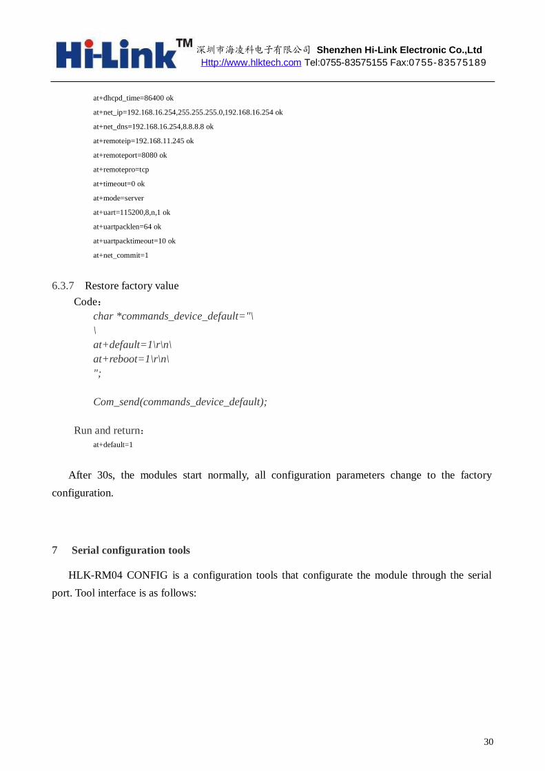
6.3.7 Restore factory value Code:
char *commands_device_default="\ \ at+default=1\r\n\ at+reboot=1\r\n\ ";
Com_send(commands_device_default);
Run and return: at+default=1
After 30s, the modules start normally, all configuration parameters change to the factory configuration.
7 Serial configuration tools
HLK-RM04 CONFIG is a configuration tools that configurate the module through the serial port. Tool interface is as follows:
深圳市海凌科电子有限公司 Shenzhen Hi-Link Electronic Co.,Ltd Http://www.hlktech.com Tel:0755-83575155 Fax:0755-83575189
31
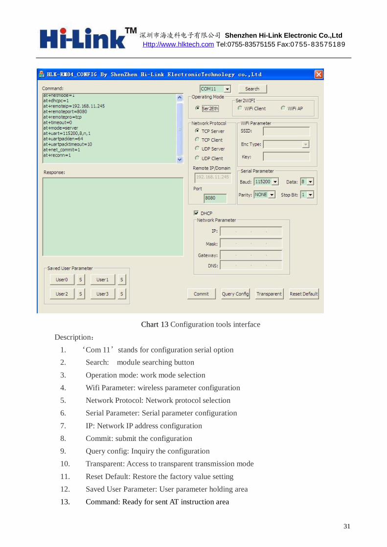
Chart 13 Configuration tools interface Description:
1. ‘Com 11’stands for configuration serial option 2. Search: module searching button 3. Operation mode: work mode selection 4. Wifi Parameter: wireless parameter configuration 5. Network Protocol: Network protocol selection 6. Serial Parameter: Serial parameter configuration 7. IP: Network IP address configuration 8. Commit: submit the configuration 9. Query config: Inquiry the configuration 10. Transparent: Access to transparent transmission mode 11. Reset Default: Restore the factory value setting 12. Saved User Parameter: User parameter holding area 13. Command: Ready for sent AT instruction area

深圳市海凌科电子有限公司 Shenzhen Hi-Link Electronic Co.,Ltd Http://www.hlktech.com Tel:0755-83575155 Fax:0755-83575189
32
14. Response: AT instruction return information area
7.1 Searching the Module
Through the "configure serial port choice" choose PC serial number and click on the "search module" button, the tool will use the specified serial search the module HLK - RM04, the module will be searched if it has been connected and in AT instruction mode . The module information will be found in the AT instruction return information area. Shown as below:
Chart 16 searching the module At this time, The PC and module have been able to establish the normal AT command
communication. All the AT interactive orders need to process based on the normal AT instruction communication.
7.2 Set each Parameters
Configurate the required function through the configuration items 3, 4, 5, 6, 7. The Configuration and modification information would immediately create the matching AT command in the ready for sent AT instruction area. The generated AT instruction will not send to the module at once. Shown as below:

深圳市海凌科电子有限公司 Shenzhen Hi-Link Electronic Co.,Ltd Http://www.hlktech.com Tel:0755-83575155 Fax:0755-83575189
33
Chart 17 Serial configuration tool generates AT command
7.3 Submit the configuration
Click the submit configuration button, the tool will send the AT instruction in the ready for sent area to the module immediately. The information of command execution results will be shown in AT instruction return information area.

深圳市海凌科电子有限公司 Shenzhen Hi-Link Electronic Co.,Ltd Http://www.hlktech.com Tel:0755-83575155 Fax:0755-83575189
34
Chart18. Serial configuration tools instruction execution
7.4 User Data Retention
The user parameter holding area provides parameter saving function. Through this function you can save up four sets of parameters at most, respectively, user0 user1, user2, user3. Click "S" button, it will pop up a confirmation dialog shown as below:
Chart 19. Pop-up Dialog of parameter saving Click on the button "yes", the instruction in the ready for sent AT instruction area will save for
user0 parameter group. After this step, when you click "user0" anytime, this parameter group can be called immediately, and covered to the ready for sent AT instruction area.
The stored user parameter will save as text file in the tools contents, file name, respectively, user0, user1, user2, user3.
7.5 Inquiry configuration
Click on the button‘inquery’, The tool will send a series of AT instructions immediately to the module to inquires the current configuration of the module, the result of execution will show in AT instruction return information area at once,each configuration items will make corresponding change with the return information.
7.6 Access to transparent transmission mode
If the module has already in the AT instruction mode, click on the button ‘T/T’, you can access to the transparent transmission mode at once.
7.7 Restore factory factory value setting
Click on the button ‘reset’, the tool will pop up a confirmed box shown as below:

深圳市海凌科电子有限公司 Shenzhen Hi-Link Electronic Co.,Ltd Http://www.hlktech.com Tel:0755-83575155 Fax:0755-83575189
35
Chart 20 Pop-up box for reset default setting Click on the button‘yes’,The tools will send AT instruction immediately,after about 30
seconds,the module will access to the default state.
8 Device Search tools
HLK-RM04_Discover is a search tool of network end used to search the module HLK-RM04.The interface is as follows:
Chart 21. Device search tools Click on the button“Discover”,the tools will search all the HLK-RMO4 module connected
with PCin the LAN.The module being searched will show in the information box soon.The module information including: IP address, MAC address and version of it.

深圳市海凌科电子有限公司 Shenzhen Hi-Link Electronic Co.,Ltd Http://www.hlktech.com Tel:0755-83575155 Fax:0755-83575189
36
9 Restore factory Settings
Support the following ways to restore the factory settings 1. Through the Web page. 2 By keeping the ES/RST pin low level time greater than Trst.
Factory setting parameter values, see the following list:
netmode 0
wifi_conf Hi-Link_,wpa2_aes,12345678
dhcpc 1
net_ip 192.168.11.254,255.255.255.0,192.168.11.1
net_dns 192.168.11.1,8.8.8.8
dhcpd 1
dhcpd_ip 192.168.16.100,192.168.16.200,255.255.255.0,192.168.16.1
dhcpd_dns 192.168.16.1,8.8.8.8
dhcpd_time 86400
remoteip 192.168.11.245
remoteport 8080
remotepro tcp
timeout 0
mode none
uart 115200,8,n,1
uartpacklen 64
uartpacktimeout 10
IP address 192.168.16.254
Wifi password 12345678
Web username/password admin/admin
>Trst
t
Reset to Default.
V(ES/RST)

深圳市海凌科电子有限公司 Shenzhen Hi-Link Electronic Co.,Ltd Http://www.hlktech.com Tel:0755-83575155 Fax:0755-83575189
37
Tes 100ms
Trst 6s
10 Firmware upgrade
1. Restore the factory value. 2. Pc can connect with module through Ethernet, ip: 192.168.16.123/255.255.255.0. Browser
visits 192.168.16.254. Username / password: admin / admin. 3. Open the following page. Select the appropriate firmware, click apply upgrades. Wait about
3 minutes. Can not cut out the upgrade process, otherwise it may cause damage to the module.
Appendix A document revision record
Version number
Revision range Date
1.00 Draft version 2012-9-10
Related Documents


![szsapo.com...0755-61886882-82218 0755-61886882-82218, chenmin@szsapo. com 0755—61886882—82212, .jxiannv@szsapo. com 1 Ilk 7926 0078 8013 0000 0143 3 N 2020 I E] 0](https://static.cupdf.com/doc/110x72/60b1284b679a765bcc3ade80/-0755-61886882-82218-0755-61886882-82218-chenminszsapo-com-0755a61886882a82212.jpg)