Welcome message from author
This document is posted to help you gain knowledge. Please leave a comment to let me know what you think about it! Share it to your friends and learn new things together.
Transcript
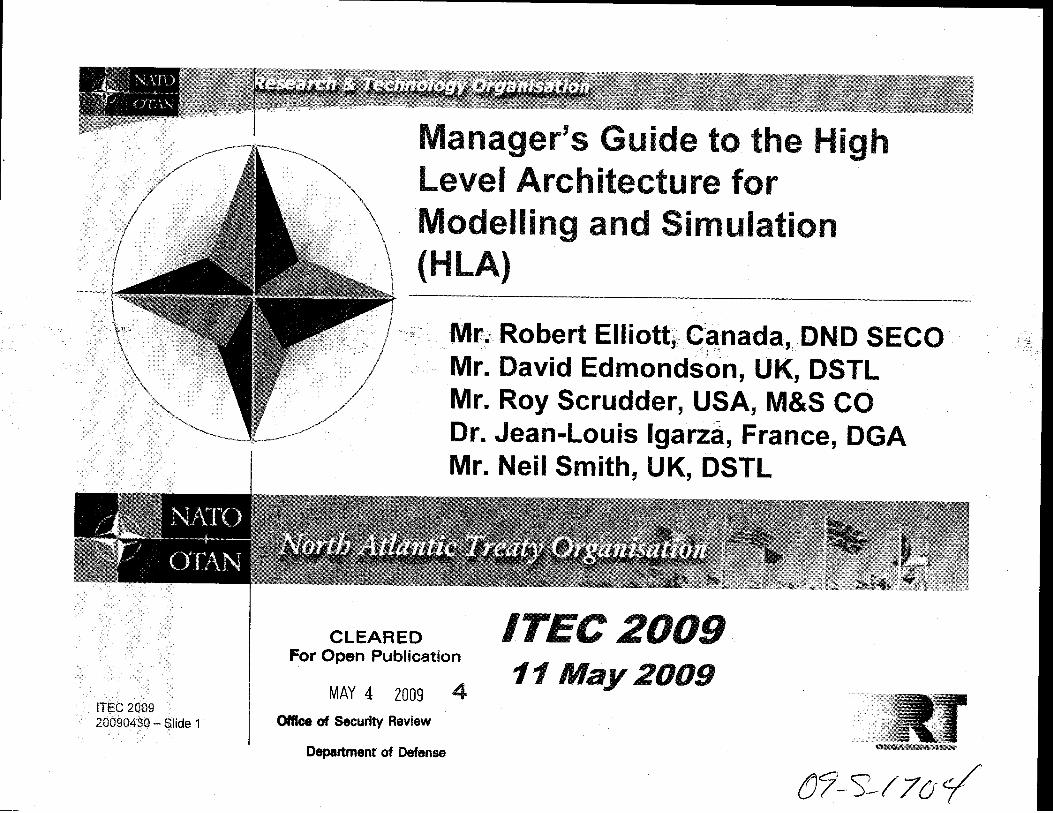

ITEC 200920090430 – Slide 1
Mr. Robert Elliott, Canada, DND SECOMr. David Edmondson, UK, DSTL Mr. Roy Scrudder, USA, M&S CODr. Jean-Louis Igarza, France, DGAMr. Neil Smith, UK, DSTL
ITEC 200911 May 2009
Manager’s Guide to the High Level Architecture for Modelling and Simulation (HLA)

ITEC 200920090430 – Slide 2
Outline
Objective
HLA Overview
Use Cases
Federation ResourceConsiderations
Federation Development Process
Summary and Wrap Up
M&S Introduction

ITEC 200920090430 – Slide 3
Objectives
Benefits of using modelling and simulationIssues to be considered to implementing M&S and HLABasic understanding of HLA conceptsBenefits of using HLASystems engineering process for HLAResources required to effectively employ HLA

ITEC 200920090430 – Slide 4
Outline
Objective
HLA Overview
Use Cases
Federation ResourceConsiderations
Federation Development Process
Summary and Wrap Up
M&S Introduction
TopicsWhat is M&S?Value of M&SDistributed simulationInteroperabilityVerification and validation

ITEC 200920090430 – Slide 5
What is Modelling and Simulation (M&S)
M&S is:a representation of the real worldan enabling tool that improves our lives today, prepares us for a better tomorrow, and provides a means to meet national and international security challenges
M&S technology and processes:exist everywhere in our livesused extensively for acquisition, analysis, experimentation, planning, testing and training
5Courtesy of Alion

ITEC 200920090430 – Slide 6
What is Modelling and Simulation?
An attempt torepresent real world:
• Processes • Equipment• People• Activities• Environments
Courtesy of Alion

ITEC 200920090430 – Slide 7
Why M&S
Aid for:Thought (Help develop and explore issues)Communication (Picture worth 1,000 words)Training and InstructionExperimentationPrediction
Improves capabilities
Canadian source
ITEC 200920090430 – Slide 8
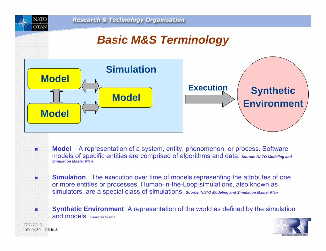
Basic M&S Terminology
Model A representation of a system, entity, phenomenon, or process. Software models of specific entities are comprised of algorithms and data. Source: NATO Modeling and Simulation Master Plan
Simulation The execution over time of models representing the attributes of one or more entities or processes. Human-in-the-Loop simulations, also known as simulators, are a special class of simulations. Source: NATO Modeling and Simulation Master Plan
Synthetic Environment A representation of the world as defined by the simulation and models. Canadian Source
SimulationModel
ModelModel
SyntheticEnvironment
Execution

ITEC 200920090430 – Slide 9
Types of Simulations
Live - Simulation involving real people operating real systems
Virtual - Simulation involving real people operating simulated systems
Constructive - Simulation involving simulated people operating simulated systems. Real people can stimulate (make inputs) but are not involved in determining outcomes.
Source: NATO Modeling and Simulation Master Plan

ITEC 200920090430 – Slide 10
Types of Simulations – Live
Live simulations:- involve individuals or groups- may use actual equipment- should provide a similar area of operations- should be close to replicating the actual activity
Live Simulation - A simulation involving real peopleoperating real systems.
Courtesy of Alion

ITEC 200920090430 – Slide 11
Types of Simulations - Virtual
Virtual Simulation - A simulation involving real people operating simulated systems.
Virtual simulations inject human-in-the-loop in a central role by exercising:• motor control skills (e.g., flying an airplane)• decision skills (e.g., committing fire control resources to action)• communication skills (e.g., members of a C4I team)
Courtesy of Alion

ITEC 200920090430 – Slide 12
Types of Simulations - Constructive
Constructive Simulation - Simulations that involvesimulated people operating simulated systems. Real people stimulate (make inputs) to such simulations, but are not involved in determining the outcomes.
Constructive simulations offer the ability to:- analyze concepts- predict possible outcomes- stress large organizations- make measurements- generate statistics- perform analysis
Courtesy of Alion

ITEC 200920090430 – Slide 13
How M&S is Used
M&S as a primary enabling technology necessary to effectively meet objectives in an affordable, reusable and interoperable contextUse M&S in relation to:
Concept development and experimentationMateriel acquisition and supportJoint and combined training and mission rehearsalDevelopment of doctrine and tacticsFormulation of new operational plans and capabilitiesAssessment of war fightingSupport for technology assessment, system upgrade, prototyping, full-scale development and forces structuringEnable testing in realistic environments that may not be practical for live testing

ITEC 200920090430 – Slide 14
Value of M&S
Saves LivesM&S supports real-world applications that save lives.
Saves Taxpayers DollarsM&S supports real-world applications that preserve taxpayer dollars and accelerate the search for solutions to national challenges.
Increases Operational CapabilityM&S provides strategic operations and support functions to our military, aids plans for national disaster responses and emergency preparedness, fosters and maintains our strategic partnerships, and enhances economic competitiveness globally.

ITEC 200920090430 – Slide 15
Why Use M&S
Enables the representation of a piece of the real world (or a conceptual world) to allow examination of factors of interest in a controlled manner.Provides preliminary design capability of both processes and physical entities to identify potential problemsProvides capability to examine interactions of multiple entities to assess performanceOffers opportunity to examine the effects of high risk situations in a safe mannerOffers the potential to reduce costs and compress schedulesCanadian source

ITEC 200920090430 – Slide 16
Using M&S to Reduce Programme /Project Risk
Use of M&S can offer preliminary assessments of a process or system to help avoid errors of conception, construction, or commissionM&S can provide representative education and training in an environment similar to the real worldM&S can provide a synthetic environment to enable rehearsal of processes and missions in a realistic settingIt is an effective communication tool to demonstrate and convey performance and design concepts and requirements
Canadian source

ITEC 200920090430 – Slide 17
M&S Challenges Across Communities
Usability, Reliability & Affordability (Time, Manpower)Rapid Scenario Generation CapabilitiesMulti-Resolution EnvironmentsHuman-Organizational Behavior
RepresentationMulti-Level Security IssuesLarge-Scale Distributed SimulationsC4ISR Systems Interface and Integration

ITEC 200920090430 – Slide 18
Risks of Using M&S
Understanding the simulation objectiveSelecting the appropriate type/mix of simulation (live, virtual, constructive)Choosing the correct resolution and fidelityFollowing a disciplined building processProviding the correct supporting databasesAdequate resourcing for the effortPresentation of the results in an understandable contextCanadian source
ITEC 200920090430 – Slide 19
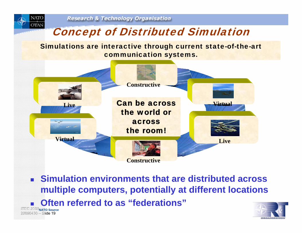
Constructive
LiveVirtual
Live Virtual
Constructive
Can be across the world or
acrossthe room!
Simulations are interactive through current state-of-the-art communication systems..
Concept of Distributed Simulation
NATO Source
Simulation environments that are distributed across multiple computers, potentially at different locationsOften referred to as “federations”

ITEC 200920090430 – Slide 20
Why Use Distributed Simulation
Allows adaptation to changing requirementsConnects simulation capability that may be in several locations, thus no requirement to moveIncreases processing capacityEnables the combination of Live, Virtual, Constructive simulationsEnables the interaction of users and observers at different locationsReuses existing capabilitiesCanadian source

ITEC 200920090430 – Slide 21
History of Distributed SimulationSIMNET
1980’s - development1987 - Fielded
DIS1992 – First I/ITSEC Demo1993 – First IEEE 1278 standards1998 – DIS Amendment2009 – DIS continues to evolve through SISO
ALSP1990 - First DARPA initiative1992 – Confederation exercises
HLA (see other slides)TENA
2002 - Architecture Document published2002 – Used in Millennium Challenge2009 – TENA continues to evolve
LVC Architecture Roadmap2007 – Initiated2009 – Final report
ITEC 200920090430 – Slide 22
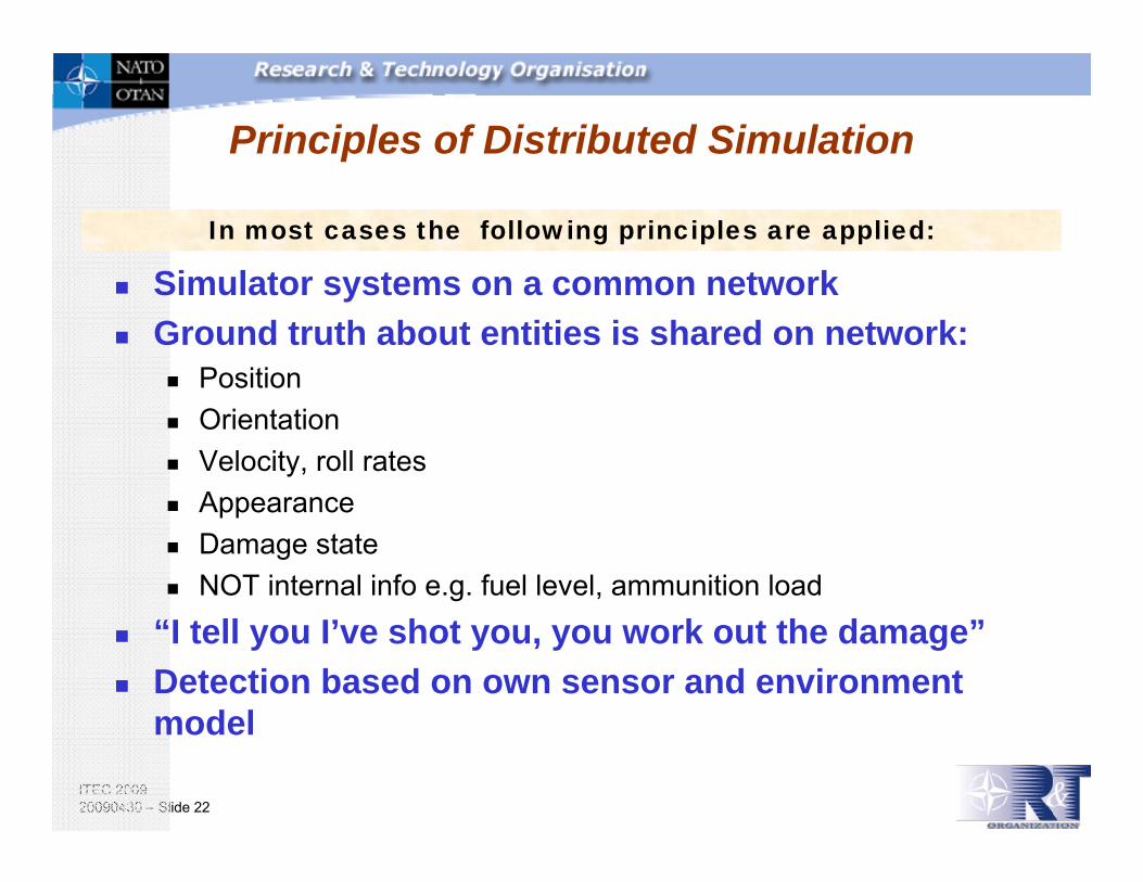
Principles of Distributed Simulation
Simulator systems on a common networkGround truth about entities is shared on network:
PositionOrientationVelocity, roll ratesAppearanceDamage stateNOT internal info e.g. fuel level, ammunition load
“I tell you I’ve shot you, you work out the damage”Detection based on own sensor and environment model
In most cases the following principles are applied:

ITEC 200920090430 – Slide 23
Distributed Simulation Components
TerrainLive SystemsComputer Generated Forces
JSAF, OOSManned Simulators
Full motionFixed
C2 SystemsSA DisplaysChat/email
Logging and AnalysisViewersRadio Comms

ITEC 200920090430 – Slide 24
Distributed Simulation Information Products
Object Model (Format) Object Model (Content) Service Specification Architecture Spec and Rules Security Rqmts/Plan Enumerations Standard Algorithms Data Logging / Collection Federation Management (SE Process)Scenario
Conceptual Model Test Plan Requirements / Objectives VV&A Products/Plan Terrain Databases Environmental Databases METOC Databases Attrition computation policy Byte Ordering Network Architecture MOE/MOP metrics

ITEC 200920090430 – Slide 25
Time ManagementReal-Time simulations
Meet visual perception and high performance requirementsMust proceed at wall clock time
Event-Stepped simulationsEvent driven requires causality to be maintainedMay proceed either faster, slower or at wall clock time
Management ApproachesNo Time Management
Each Simulation Advances Time at Its Own PaceConservative Synchronization
Simulations Advance Time Only When Guaranteed That No Past Data Will Be Received
Optimistic SynchronizationFree to Advance Logical Time, May Have Roll-back
Activity ScanAdvance Time by Mutual Agreement With Other Simulation
ITEC 200920090430 – Slide 26
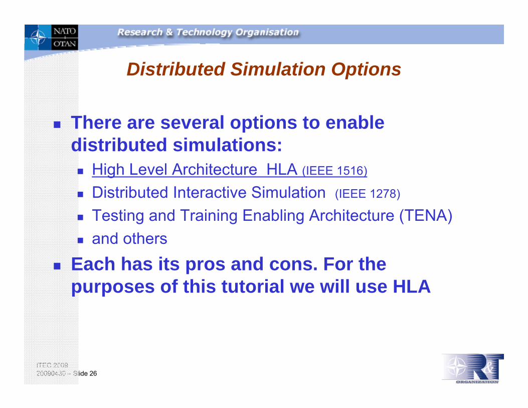
Distributed Simulation Options
There are several options to enable distributed simulations:
High Level Architecture HLA (IEEE 1516)
Distributed Interactive Simulation (IEEE 1278)
Testing and Training Enabling Architecture (TENA)and others
Each has its pros and cons. For the purposes of this tutorial we will use HLA
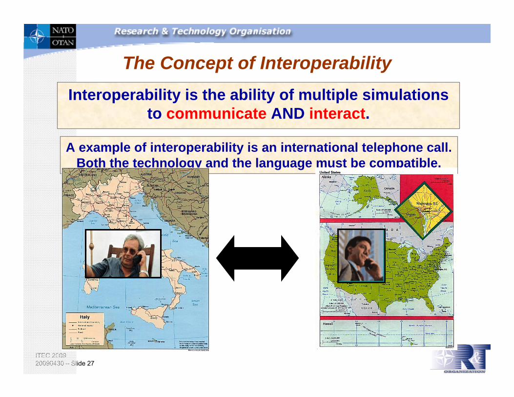
ITEC 200920090430 – Slide 27
The Concept of InteroperabilityInteroperability is the ability of multiple simulations
to communicate AND interact.
A example of interoperability is an international telephone call. Both the technology and the language must be compatible.

ITEC 200920090430 – Slide 28
Why Interoperability for M&S?
Today’s operations are joint and combined so we need to train together.
Defense operations: Army, Navy, Air Force, etcNational and InternationalOOTW: Peace support operations, Crisis management, Civil security. This also involves civilian entities All levels: from tactical/operational to command and control/strategic/theater level
Need to procure from different suppliers/organizationsDifferent domain modeling and simulation expertise is found in different organizationsOpen acquisition model for competitive price/performance.Economics of modeling and simulations, for example reuse

ITEC 200920090430 – Slide 29
Considerations for Distributed Simulations
Network capability – bandwidth and quality of serviceSecurity - is a secure network required and are the various locations accredited for secure useNetwork support tools – does the network have the required support tools available to enable the simulation developers and operators to communicate and resolve problemsCommon simulation tools – does the simulation have a common tool to manage the simulation, exchange the required data and monitor performanceSimulation interoperability – are the various parts of the simulation interoperable; both technically and contextually
Canadian source

ITEC 200920090430 – Slide 30
The Purpose & Importance of Verification, Validation, and Accreditation
Provide credibility to the simulation results through a disciplined approachEnsure Fit for PurposeProvide Documented Evidence of what was testedProvide a documented basis for formal Accreditation where requiredProvide a documented reference history to assess possible reuse

ITEC 200920090430 – Slide 31
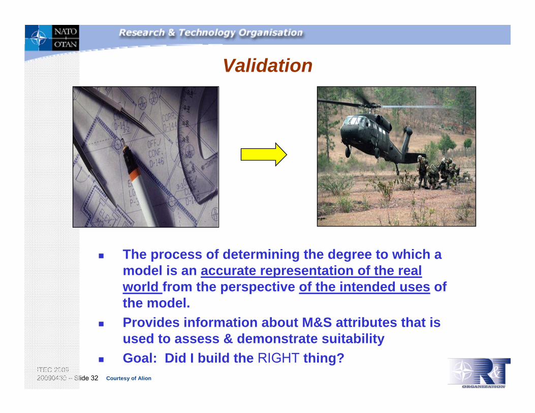
Verification
The process of determining that a model implementation accurately represents the developer's conceptual description and specifications.Provides information about M&S attributes that is used to assess & demonstrate suitabilityGoal: Did I build it RIGHT?
Courtesy of Alion
ITEC 200920090430 – Slide 32
Validation
The process of determining the degree to which a model is an accurate representation of the real world from the perspective of the intended uses of the model. Provides information about M&S attributes that is used to assess & demonstrate suitabilityGoal: Did I build the RIGHT thing?
Courtesy of Alion

ITEC 200920090430 – Slide 33
Accreditation
The official certification that a model, simulation, or federation of models and simulations and its associated data are acceptable for use for a specific purpose. The certification is based on the accreditation assessment. Goal: Are the results of the M&S FIT FOR PURPOSE and USEFUL for making decisions?Other commonly used terms are “acceptance” and “fit for purpose”
Graphics Courtesy of Alion

ITEC 200920090430 – Slide 34
VV&A Considerations
Efficient V&V is conducted concurrently with model developmentA precise specification of the intended purpose is essentialV&V of a simulation model does not equal quality assuranceof eg. SoftwareMeaningful validation requires sufficient data, information, and knowledge about both the system of interest and the simulation modelCost-efficient V&V is risk-driven
Risk Resources
Balancing the cost of knowing against the risk
of assuming.
Graphic courtesy of S. Youngblood, JH APL

ITEC 200920090430 – Slide 35
New M&S DevelopmentAny stand-alone model or simulation under development being built to address the intended purpose or purposes of the User.
LegacyAny model or simulation that was developed either in the past or for a different purpose.
FederationA system of interacting models and/or simulations, with supporting infrastructure, based on a common understanding of the objects portrayed in the system.
Where Does VV&A Apply?

ITEC 200920090430 – Slide 36
OutlineObjective
HLA Overview
Use Cases
Federation ResourceConsiderations
Federation Development Process
Summary and Wrap Up
M&S Introduction
TopicsMotivationHistoryCore conceptsUpcoming changesStandardsCompliance testing

ITEC 200920090430 – Slide 37
HLA Motivation
Basic Premises:No single, monolithic simulation can satisfy the needs of all usersAll uses of simulations and useful ways of combining them cannot be anticipated in advanceFuture technological capabilities and a variety of operating configurations must be accommodated
Need composable approach to constructing simulation federationsHLA evolved from key Aggregate-Level Simulation Protocol (ALSP) and Distributed Interactive Simulations (DIS) architectural decisions

ITEC 200920090430 – Slide 38
High Level Architecture Strengths
The HLA is an internationally recognised Open Standard (ref: IEEE 1516.x) Scalability - can scale up to very large exercises, e.g. 1000’s of simulation entitiesThe architecture can be implemented across different computing environmentsProvides a process for developing and documenting a distributed simulation interface specification, i.e. the Federation Object Model (FOM)Supports real-time, faster than real-time and event driven time domainsThe HLA has been proven to work
UK Source
Source: UK IMMSA Guide, DSTL

ITEC 200920090430 – Slide 39
High Level Architecture
The objectives of the HLA are to:Establish a common development and execution architecture to facilitate the interoperability of all types of models and simulations (including real-time, faster than real-time, event-driven simulations and command and control systems)Facilitate the re-use of Modelling & Simulation (M&S) components
The High Level Architecture (HLA) is not an implementation but is a documented open architecture,The High Level Architecture is comprised of three elements:
A set of HLA RulesHLA Rules for Federates and Federations which define relationships among federating compliant simulationsAn Object Model Template (OMT) SpecificationObject Model Template (OMT) Specification which specifies the form in which simulation elements are describedAn Interface SpecificationInterface Specification which describes the way compliant simulations interact during operation

ITEC 200920090430 – Slide 40
HLA Issues
As an open standard, changes to the specifications may occur based on consensusChanges to future HLA standards may have significant impact on local implementationsMigration from earlier versions (US DoD version) to the open standards IEEE version has been slow in some countriesHigh dependence on vendors for software tools

ITEC 200920090430 – Slide 41
HLA – Past, Present and Future
HLA 1.0HLA 1.1
HLA 1.2
HLA 1.3Reviseevery
5 years
Align with XMLRevise DDM
Specified data types
Fault ToleranceWeb ServicesFOM Modules
Smart Update Rate ReductionDynamic Link Compatibility
More
A Technical Perspective
Features and updatesbased on:
New requirementsNew opportunities
19981995 2000 2009
HLA EvolvedHLA 1516
ProtofederationsUS & International Federations
Courtesy of Pitch

ITEC 200920090430 – Slide 42
The Classic HLA ”Lollipop” View
Each participating member is called a federateInformation is exchanged using an RTIThe information exchange follows a Federation Object Model (FOM)The participating federates together with the FOM are called a federation
Run-Time Infrastructure (RTI)
Federate A Federate B Federate C Federation Object Model<FOM><Shared object classes><Shared interaction classes><More>
</FOM>
Courtesy of Pitch

ITEC 200920090430 – Slide 43
How HLA Works ”Information Bus”
A federate can publish the information that it produces to the federationAnother federate can subscribe to information that it requiresPublishing and subscribing are based on the FOM The RTI routes any relevant information to a subscribing federate – no need for federates to connect directly to other federatesEnables interoperability and reuseAllows for multiple RTI implementations, including central server and peer-to-peer
Run-Time Infrastructure
Federate A Federate B Federate C Federate X
Publish truck, aircraft, commandSubscribe aircraft, weather, command
Publish weather
Subscribe command
Publish aircraft, commandSubscribe aircraft, weather, command
Publish truck, aircraftSubscribe truck, aircraft
Source: SISO Euro SIW 2008 HLA Evolved –Improvements and Benefits: Möller et al
Courtesy of Pitch

ITEC 200920090430 – Slide 44
Range of HLA Usage
LiveParticipants
Support Utilities
Interface
Interfaces toLive Players
Runtime Infrastructure (RTI)
Simulations
Applicable to broad range of functional areas (e.g., training, contingency planning, analysis, and acquisition)Applicable to simulations involving pure software representations, man-in-the-loop simulators, and interfaces to live components (e.g., instrumented-weapon systems and C3 systems)

ITEC 200920090430 – Slide 45
HLA – Sample Federation
Run-Time Infrastructure
Interface to Live players & systems
Interface to C4I Systems
Platform Trainers
Computer Generated ForcesStaff-Level Training / CAX
C4I Sensor Staff F16 CGF
Source: SISO Euro SIW 2008 HLA Evolved –Improvements and Benefits: Möller et al
Courtesy of Pitch

ITEC 200920090430 – Slide 46
High Level Architecture Terminology
A federate – an application that may be, or is coupled with other software applications under a Federation Object Model Document Data (FDD) and a runtime infrastructure (RTI)A federation – a named set of federate applications and a common Federation Object Model that are used as a whole to achieve some specific objectiveA Simulation Object Model (SOM) – a specification of the types of information that an individual federate could provide to HLA federations as well as the information a federate could receive from other federates in HLA federations.A Federation Object Model (FOM) – a specification defining the information exchanged at runtime to achieve a given set of federation objectives. Object Model Template - a standardised format , rules and terminology used for describing HLA object models, i.e.
Objects - a thing e.g. TankAttributes - about an object e.g. positionInteractions - between models
Run Time Infrastructure (RTI) The software that provides common interface services during a HLA federation execution for synchronization and data exchange.
IEEE 1516-2000

ITEC 200920090430 – Slide 47
What is a HLA Runtime Infrastructure (RTI)
It is a software package designed to manage a federation in a manner consistent with the HLA specification. It is the service interface amongst federates
It achieves data distribution, and provides a set of common services. Think of it a telephone switchboard. It provides the connection and maintains a common level of service.
It does not maintain any information on the state of the federation, nor information on the data content and format etc.
HLA RTIs are available from commercial vendors, national implementations; some movement to open source

ITEC 200920090430 – Slide 48
RTI and Tool Implementations
Mainly from US, Europe and AsiaRuntime Infrastructure implementations
~5 COTS RTIs~10 Additional actively developed/maintained RTIs
Company in-house, government projects, open-source, etc~10 Other serious RTI implementation>100 Experimental or student RTIs
Hundreds of HLA compatible COTS applications: general purpose tools and domain specific federates
Data loggers, management tools, middleware, code generators, platform simulators, visualizations, computer generated forces,...
Courtesy of Pitch

ITEC 200920090430 – Slide 49
RTI PerformanceBased on public information from several RTI vendors:
Tens to hundreds of interoperating systems in one federation100 000 entities or moreApproximately 50 000 updates per secondHigh data throughput, for example 600 Mpbs on Gigabit network using WindowsLow latency, for example: 0.130 milliseconds (130 μs) latency between Windows hosts on a LAN
Actual performance may vary between RTI vendors, hardware configurations and simulators usedPerformance of an actual federation will generally be limited by data consumption/production rate of participating systems or network latency/bandwidth
Source: SISO Euro SIW 2008 HLA Evolved –Improvements and Benefits: Möller et alCourtesy of Pitch

ITEC 200920090430 – Slide 50
HLA Specifications
HLA Framework and RulesIEEE 1516-2000
HLA Federate Interface SpecificationIEEE 1516.1-2000
HLA Object Model Template IEEE 1516.2-2000
Federation Development and Execution Process (FEDEP) Recommended Practice
IEEE 1516.3-2003Recommended Practice for Verification, Validation, and Accreditation of a Federation—An Overlay to the High Level Architecture Federation Development and Execution Process
IEEE 1516.4-2007
ITEC 200920090430 – Slide 51
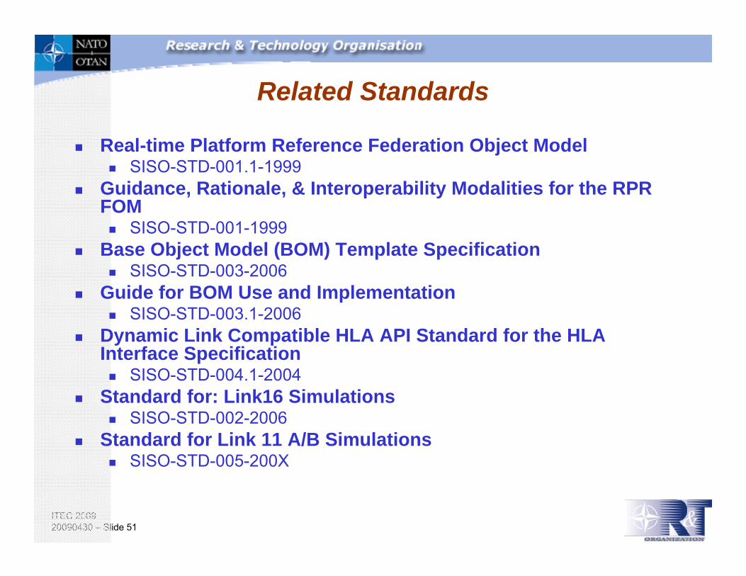
Related Standards
Real-time Platform Reference Federation Object Model SISO-STD-001.1-1999
Guidance, Rationale, & Interoperability Modalities for the RPR FOM
SISO-STD-001-1999Base Object Model (BOM) Template Specification
SISO-STD-003-2006Guide for BOM Use and Implementation
SISO-STD-003.1-2006 Dynamic Link Compatible HLA API Standard for the HLA Interface Specification
SISO-STD-004.1-2004Standard for: Link16 Simulations
SISO-STD-002-2006Standard for Link 11 A/B Simulations
SISO-STD-005-200X

ITEC 200920090430 – Slide 52
HLA 1516 Framework and Rules
5 Rules for Federations1. Federations shall have an HLA Federation Object Model (FOM),
documented in accordance with the HLA Object Model Template (OMT).
2. In a federation, all simulation-associated object instance representation shall be in the federates, not in the runtime infrastructure (RTI).
3. During a federation execution, all exchange of FOM data among federates shall occur via the RTI.
4. During a federation execution, federates shall interact with theRTI in accordance with the HLA interface specification.
5. During a federation execution, an instance attribute shall be owned by at most one federate at any given time.

ITEC 200920090430 – Slide 53
HLA 1516 Framework and Rules
5 Rules for Federates6. Federates shall have an HLA Simulation Object Model (SOM),
documented in accordance with the HLA Object Model Template (OMT).
7. Federates shall be able to update and/or reflect any attributes and send and/or receive interactions, as specified in their SOMs.
8. Federates shall be able to transfer and/or accept ownership of attributes dynamically during a federation execution, as specified in their SOMs.
9. Federates shall be able to vary the conditions (e.g., thresholds) under which they provide updates of attributes, as specified in their SOMs.
10. Federates shall be able to manage local time in a way that will allow them to coordinate data exchange with other members of a federation.

ITEC 200920090430 – Slide 54
HLA Federate Interface Specification
Defines a set of services provided by federates and an RTIService groups
Federation Management (31 services)Declaration Management (12 services)Object Management (20 services)Ownership Management (18 services)Time Management (23 services)Data Distribution Management (12 services)Support Services (43 services)
Management Object ModelFOM Document Data (FDD) XML Schema DeclarationApplication Programmers Interfaces (APIs) in C++, Java, and WSDL
HLA IF Spec V1.3Mod 012 February 2001 54

ITEC 200920090430 – Slide 55
HLA Object Model Template
A standard template for use in defining both Federation Object Models (FOMs) and Simulation Object Models (SOMs)Defined in terms of a series of interrelated tablesDefines a XML data interchange formatProvides a template to define federate capabilities for conformance checking
ITEC 200920090430 – Slide 56
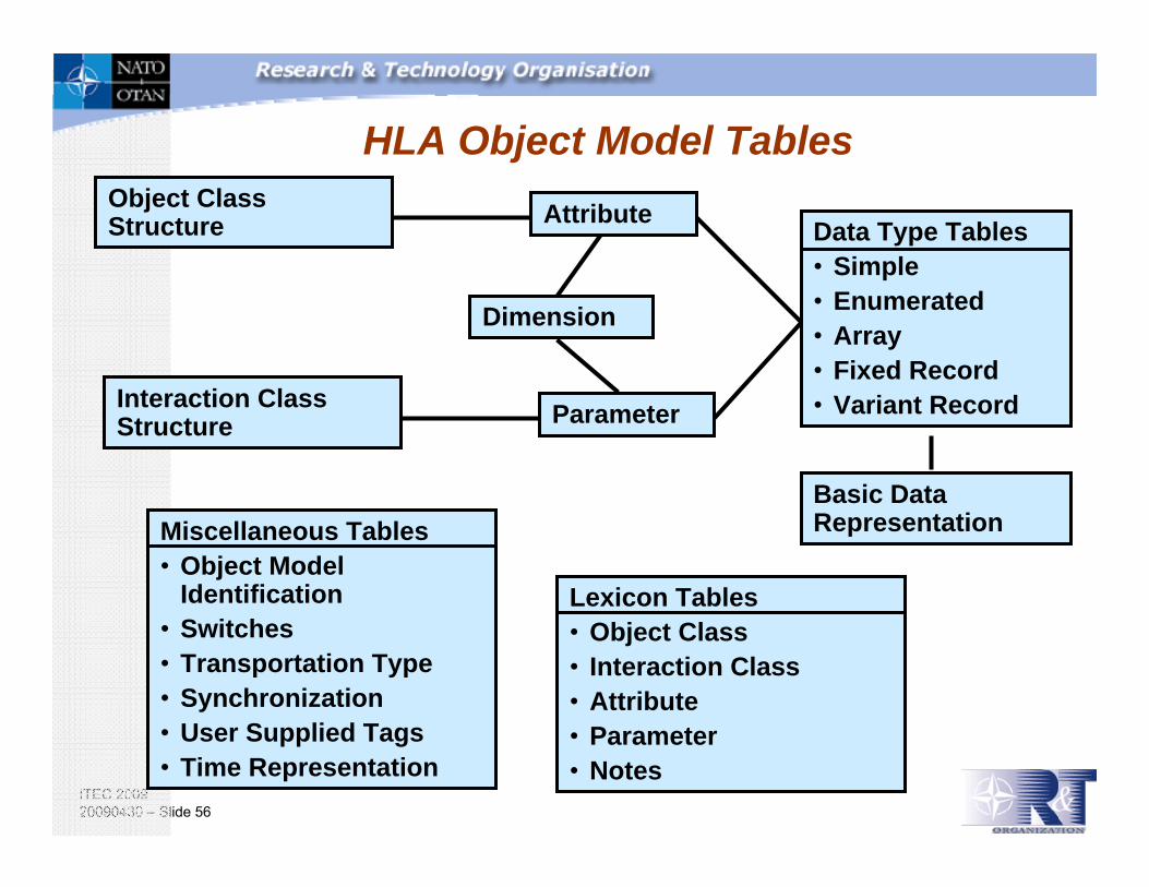
HLA Object Model TablesObject Class Structure
Interaction Class Structure
Attribute
Parameter
Miscellaneous Tables• Object Model
Identification• Switches• Transportation Type• Synchronization• User Supplied Tags• Time Representation
Data Type Tables• Simple• Enumerated• Array• Fixed Record• Variant Record
Basic Data Representation
Lexicon Tables• Object Class• Interaction Class• Attribute• Parameter• Notes
Dimension

ITEC 200920090430 – Slide 57
FOM –Object Class Structure Example
Source: SISO Euro SIW 2008 HLA Evolved –Improvements and Benefits: Möller et al
Courtesy of Pitch

ITEC 200920090430 – Slide 58
The HLA Evolved Effort
Updating the current IEEE 1516-2000 series of technical specifications for HLAAll IEEE products must be reviewed every 5 years and either reaffirmed, opened for revision and re-balloted, or retiredImportant sources for revision:
210 ”interpretations” by the US DoDDynamic Link Compatibility API by SISOHundreds of formal comments from HLA users during three ”comment rounds”
Source: SISO Euro SIW 2008 HLA Evolved –Improvements and Benefits: Möller et al

ITEC 200920090430 – Slide 59
HLA Evolved Status
Completed three draft review roundsCompleted first ballot
Met thresholds for % of ballots returned and % of votes to approve the specificationCurrently resolving nearly 500 comments
Will recirculate the ballot per IEEE rulesExpect publication at the end of 2009
Source: SISO Euro SIW 2008 HLA Evolved –Improvements and Benefits: Möller et al
ITEC 200920090430 – Slide 60
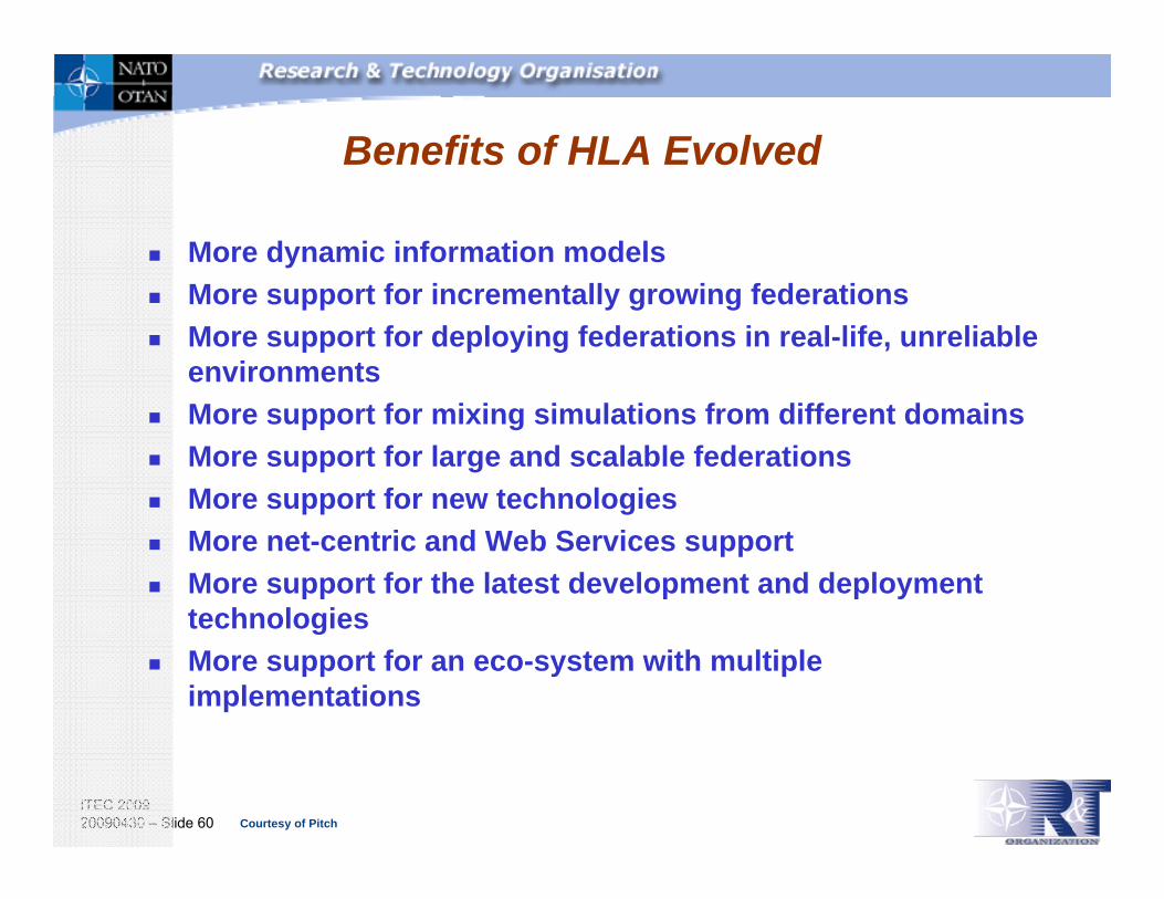
Benefits of HLA Evolved
More dynamic information modelsMore support for incrementally growing federationsMore support for deploying federations in real-life, unreliable environmentsMore support for mixing simulations from different domainsMore support for large and scalable federationsMore support for new technologiesMore net-centric and Web Services supportMore support for the latest development and deployment technologiesMore support for an eco-system with multiple implementations
Courtesy of Pitch

ITEC 200920090430 – Slide 61
...and Some Good Newsabout the Current Features
HLA Evolved doesn’t change any semantics in the current HLA 1516 standard.It simply adds new features.If you invested time in learning HLA you will still benefit from that knowledge!
Note: APIs and file formats have been updated – some effort needed to migrate applications

ITEC 200920090430 – Slide 62
HLA Standards and Their DevelopmentHLA – Developers and Users
HLA (IEEE 1516) is developed as an open international standard through a Product Development Group (PDG) as part of SISO (www.sisostds.org)
SISO is an IEEE Standards SponsorThe largest group of the PDG participants are from the US but there is also a substantial number of international participants
NATO Standardization Agreement (STANAG) 4603 establishes HLA as the standard for NATO M&S interoperability
The largest HLA user base is within defense (Live, Virtual and Constructive) but there is also a growing number of civilian users
Source: SISO Euro SIW 2008 HLA Evolved –Improvements and Benefits: Möller et al

ITEC 200920090430 – Slide 63
HLA is an Open International Standard
IEEE
Simulation Interoperability Standards Organization
(SISO)*
HLAIEEE1516
Standards
SimulationDevelopers &
Users
RTI and ToolDevelopers
Academia
- Government- Industry- Academia- Etc
- COTS- GOTS- In-house- Open source- Other
Community feedback
- Research- Student proj.- Courses
Sponsor
* SISO is a NATO-recognized standards developer
Representation in SISO/IEEE from organizations using HLA is critical
Courtesy of Pitch

ITEC 200920090430 – Slide 64
NATO HLA Policy
NATO HLA policy is contained in STANAG 4603Basically, NATO policy is to use HLA 1516 Standard as the principle enabling architecture for Modelling and Simulation ActivitiesNations that have ratified STANAG 4603
CanadaCzech RepublicDenmarkFranceGermanyHungaryThe NetherlandsUnited KingdomUnited States

ITEC 200920090430 – Slide 65
Why HLA for NATO ?
Military operations are supported by coalitions, Involving different nations , different cultures,
New nations joining NATO ...
Training of multi-national joint forces and their staff shall use national M&S capabilities:
Interoperability provided by HLA is key
HLA officially recognized by the highest authority in NATO, the North Atlantic Council (NAC) as early as 1998
Many current and future NATO projects based on HLAexamples: FIRST WAVE (Sept.2004), SMART, SNOW LEOPARD (starting in 2007) all supported by HLA federations !

ITEC 200920090430 – Slide 66
HLA RTI Verification Testing
Extensive test (~2000 tests) for compliance with HLA standardPerformed on behalf of US DoD/MSCOCommercial, government owned, and open source 1.3 and 1516 RTIs fully or partially verified: DoD, Fraunhoffer, MAK, MATREX, Pitch, Portico, Ratheon-VTCSee http://www.msco.mil/RTIVerificationService.htmlfor
Information to submit an RTI for testingList of currently verified RTIs
Source: SISO Euro SIW 2008 HLA Evolved –Improvements and Benefits: Möller et al

ITEC 200920090430 – Slide 67
HLA Federate Compliance Testing
Tests the use of HLA services by a single federatePerformed by US and a growing number of NATO/PFP countries: Canada, France, Spain, Sweden, United KingdomOver 250 HLA federates tested since 1997
Source: SISO Euro SIW 2008 HLA Evolved –Improvements and Benefits: Möller et al

ITEC 200920090430 – Slide 68
The NATO/PfP solution forHLA Certification
Implement a distributed capability between some voluntary nations,Use an common process and common software (based on the US certification suite)Evolutions controlled by NATO and PfP nationsinvolved in a common working group: the MSG-050 Certification Advisory Group (CeAG)Outside the US, HLA certification is now available in France, Spain and, Sweden, coming soon in Canada and UK

ITEC 200920090430 – Slide 69
NATO federations could be composed of federatesfrom very different origin,with diverse levels of capability,where the reliability and history of the federates is not widely known
HLA compliance testing and certification isNot considered as mandatory by NATO.Rather considered as a normal step on the way to technical interoperability of simulations.Provided as a common service availableto the NATO and Partners community.
Why HLA compliance testingwithin NATO?

ITEC 200920090430 – Slide 70
Outline
Objective
HLA Overview
Use Cases
Federation ResourceConsiderations
Federation Development Process
Summary and Wrap Up
M&S Introduction
TopicsStaffing/rolesComponents

ITEC 200920090430 – Slide 71
Federation Resources (Staffing/Roles)
Problem Setter(s):The individual or group (customer/stakeholders) that pose the question to be answered by the federationResponsible for defining the problem and for funding the means to obtain the solutionCustomer/stakeholder resources include,
end user(s)members of an Integrated Project Teamdefence analysts
Problem Solver(s):The individual or group responsible for investigating a solution to the problem space, i.e. determines if a simulation federation can provide a satisfactory solution and if so, defines and designs the federation architecture and evaluation methodsResources include,
federation project managerfederation/federate (simulation) designers

ITEC 200920090430 – Slide 72
Federation Resources (Staffing/Roles)
Federation Developers:The individual or group that develop and integrate the various elements of the federation, i.e. the specialist engineers who provide an operational and fully tested federated simulationResources include,
federation systems engineer(s)test engineersdatabase developers

ITEC 200920090430 – Slide 73
Federation Resources (Staffing/Roles)
Federation Operators:The individual or group that participate in the execution of the federation, i.e. the people interacting with the federate components, such as a platform simulator (virtual federate) or aSemi Automated Force (constructive federate)Resources include,
military operational users / Subject Matter Experts (SMEs)Instructors / role players (e.g. CGF role players)human factor specialists

ITEC 200920090430 – Slide 74
Federation Resources (Staffing/Roles)
Exercise ControllerThe person who is responsible for overall operation of the federation during runtime execution, re: starting/stopping/pausing the exercise
Verification & Validation (V&V) Agents:The individual or group designated by the customer sponsor to perform verification and validation tasks on a federation or single federatesCan be a subject matter expert within the application domain of the federation, a software/hardware specialist or a tester, who is in charge of conducting tests according to FEDERATION TEST CRITERIAInvolved across all federation activities (e.g. requirements capture, design, development) and also participate in the operation of the federation

ITEC 200920090430 – Slide 75
Federation Resources (Staffing/Roles)
Federation AnalystsThe individual or group responsible for defining data capture / analysis requirements for After Action Review (AAR)

ITEC 200920090430 – Slide 76
Federation Resources (Staffing/Roles)
Depending on the complexity of the federation one individual might fulfil more than one role across federation design, development and execution
ITEC 200920090430 – Slide 77
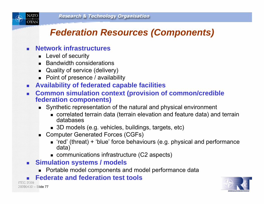
Federation Resources (Components)Network infrastructures
Level of securityBandwidth considerationsQuality of service (delivery)Point of presence / availability
Availability of federated capable facilitiesCommon simulation context (provision of common/credible federation components)
Synthetic representation of the natural and physical environmentcorrelated terrain data (terrain elevation and feature data) and terrain databases3D models (e.g. vehicles, buildings, targets, etc)
Computer Generated Forces (CGFs)‘red’ (threat) + ‘blue’ force behaviours (e.g. physical and performance data)communications infrastructure (C2 aspects)
Simulation systems / modelsPortable model components and model performance data
Federate and federation test tools

ITEC 200920090430 – Slide 78
Outline
Objective
HLA Overview
Use Cases
Federation ResourceConsiderations
Federation Development Process
Summary and Wrap Up
M&S Introduction
TopicsFederation Development and Execution Process (FEDEP)Federation Agreement Document

ITEC 200920090430 – Slide 79
HLA Federation Development and Execution Process (FEDEP)
A systems engineering process model to combine individual applications (federates) into distributed simulation environments (federations),
First a DoD Standard (FEDEP 1.5, Dec. 99, based on HLA DoD 1.3),Standardized as IEEE 1516.3-2003Not specific to HLA, but written using HLA terminologyCurrently under revision:
will be replaced by the Distributed Simulation Environment Engineering Process (DSEEP) as IEEE P1730.
Graphic courtesy of DND SECO, based on IEEE 1516.3

ITEC 200920090430 – Slide 80
FEDEP Description
Standardized systems engineering process
Recommended practice (IEEE STD 1516.3)
Federation characteristicsHigh Level Architecture (HLA) federatesDistributed environment
Benefits of FEDEPRe-useInformation sharingInteroperability

ITEC 200920090430 – Slide 81
FEDEP Seven Step Model
Define Federation Objectives
1
Perform Conceptual
Analysis
2
Design Federation
3
Develop Federation
4
Plan,Integrate, and Test
Federation
5
Execute Federation
and Prepare Outputs
6 7
Analyze Data and Report
Results
Iterative Development Flow
Design and Development
Integration and Execution
Graphic courtesy of DND SECO, based on IEEE 1516.3

ITEC 200920090430 – Slide 82
Step 1: Define Federation Objectives
Existing Domain Descriptions
Needs Statement
Federation ObjectivesStatement
Overall Plans
Info on Available Resources
Initial Planning Documents
Define Federation Objectives
(2 activities)
1
Considerations• What does the “sponsor” want to achieve?• How is success or failure going to be measured?• What are the requirements?• What’s the best way to get there?• What are you just stuck with?• The sponsor’s objectives need to be turned into detailed requirements.• Note: the level of effort required will vary
Graphic courtesy of DND SECO, based on IEEE 1516.3
ITEC 200920090430 – Slide 83
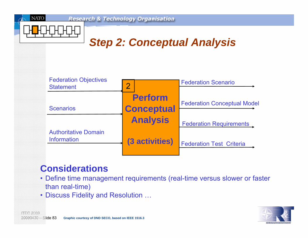
Step 2: Conceptual Analysis
Scenarios
Federation Scenario
Federation Conceptual Model
Federation Requirements
Federation Objectives Statement
Authoritative DomainInformation
Federation Test Criteria
PerformConceptual
Analysis
(3 activities)
2
Considerations• Define time management requirements (real-time versus slower or faster
than real-time)• Discuss Fidelity and Resolution …
Graphic courtesy of DND SECO, based on IEEE 1516.3
ITEC 200920090430 – Slide 84
What is a scenario?
1) Description of an exercise (“initial conditions” in military
terms). It is part of the session database that configures the
units and platforms and places them in specific locations with
specific missions. Source: NATO Modeling and Simulation Master Plan
2) An initial set of conditions and time line of significant
events imposed on trainees or systems to achieve exercise
objectives. Source: NATO Modeling and Simulation Master Plan

ITEC 200920090430 – Slide 85
Fidelity vs. Resolution
• Resolution and Fidelity are not the same• You can have one and not the other• Not necessarily a bad thing –It depends on what you are trying to accomplish
vsvs
Fidelity Resolution
Courtesy of Alion

ITEC 200920090430 – Slide 86
Fidelity
A model or simulation is said to have fidelity if it accurately corresponds to or represents the item or experience it was created to emulate. In other words, how does it act?
Fidelity: The accuracy of the representation when compared to the real world.
DoD M&S GLOSSARY, Jan 98
Courtesy of Alion
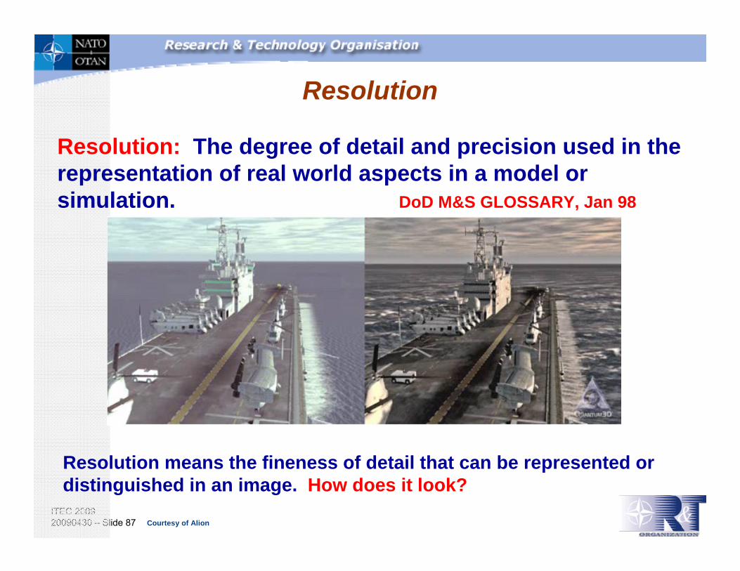
ITEC 200920090430 – Slide 87
Resolution
Resolution: The degree of detail and precision used in the representation of real world aspects in a model or simulation. DoD M&S GLOSSARY, Jan 98
Resolution means the fineness of detail that can be represented or distinguished in an image. How does it look?
Courtesy of Alion

ITEC 200920090430 – Slide 88
Step 3: Design Federation
Federate Simulation Object Models (SOMs)
Initial Planning Documents
Federation Scenario
Federation Conceptual Model
Allocated Federates
Federation Requirements
Federation Development Plan
Design Federation
(3 activities)
3
Design Federation
(3 activities)
3
ConsiderationsThe sponsor’s requirements need to be met.• Existing software, new software, and integration.• Security considerations.• Who is going to do the work?• When is all this going to happen?
Graphic courtesy of DND SECO, based on IEEE 1516.3

ITEC 200920090430 – Slide 89
Step 4: Develop Federation
Implemented Federation Infrastructure
Run Time Infrastructure (RTI) Initialization Data
Allocated Federates
Development Plan
Modified Federates
Supporting Resources
Federation Object Model (FOM)
Federate Designs
Scenario(s)
Conceptual Model
Federation Object Models
Develop Federation
(4 activities)
4
Develop Federation
(4 activities)
4
ConsiderationsDevelopment is the implementation of the plan. Some of the things that happen during development are:• Software is created.• Networks are stood-up.• Physical infrastructure is established• Contracts are let, resources are allocated.• Hardware and software are acquired.• Time management agreements are established.
Graphic courtesy of DND SECO, based on IEEE 1516.3

ITEC 200920090430 – Slide 90
Development is the implementation of the plan. Some of the things that happen during development are:
• Software is created.• Networks are stood-up.• Contracts are let, resources are allocated.• The pieces are integrated.• Hardware and software are acquired.• Testing.• Training.
In Step 4: Develop Federation …

ITEC 200920090430 – Slide 91
Step 5: Plan, Integrate, and Test Federation
Implemented Federation Infrastructure
Integrated FederationFederation Agreements
Scenario Instance(s)
FOM Document Data (FDD)
Tested Federation
Federation Environment DescriptionFederation Development Plan
FOMFederation Test Criteria
Modified / New Federates
Supporting Databases
Plan,Integrate, and Test
Federation
(3 activities)
5
Considerations•The pieces are integrated.•Testing.•Training.
Graphic courtesy of DND SECO, based on IEEE 1516.3

ITEC 200920090430 – Slide 92
Step 6: Execute Federationand Prepare Outputs
Tested Federation
Derived Outputs
Documented Execution Problems
Federation Development Plan
Federation Environment Description
Federation Agreements
Execute Federation
and Prepare Outputs
(2 activities)
6
ConsiderationExecution often leads to changes in requirements, or uncovers problems, and iteration between execution and previous stages is normal.
Graphic courtesy of DND SECO, based on IEEE 1516.3

ITEC 200920090430 – Slide 93
Step 7: Analyze Data and Evaluate Results
Federation Objectives Statement Lessons Learned
Federation Requirements
Derived Outputs
Federation Test Criteria
Final Report
Reusable Federation Products
7
Analyze Data
and Report Results
(2 activities)
ConsiderationsWas the federation “fit for purpose”?Can any of the work be reused?Are more iterations required to meet the sponsor’s objectives?
Graphic courtesy of DND SECO, based on IEEE 1516.3
ITEC 200920090430 – Slide 94
Security
Security considerations are pervasive throughout the FEDEP
Step 1 - Define Federation ObjectivesIdentify security requirements
Step 2 - Perform Conceptual AnalysisDefine security requirements for hardware, network, data, and software
Step 3 – Design FederationAnalyze, and if necessary, refine initial security risk assessment and concept of operationsDevelop security plan
Step 4 – Develop FederationEstablish security procedures
Step 5 – Plan, integrate, and test federationPerform security certification testing

ITEC 200920090430 – Slide 95
Risk
Consider risk in all steps of the FEDEPA measure of the probability and severity of undesired effects often taken as the simple product of probability and consequenceImpact
Domains: health, environment, finance…Levels: negligible, marginal, critical, catastrophic
Likelihood of occurrenceLow, medium, highProbability Theory
Residual uncertaintyUpper bound for the probability of occurrence

ITEC 200920090430 – Slide 96
Processes and Tools Considerations
Are there processes and tools available?
Yes Reports and papers for guidanceDevelopment processes tailored to M&SEvaluation Processes such as VV&AM&S tools available for a wide range of applications

ITEC 200920090430 – Slide 97
SISO FEDEP V&V Overlay
Diagrammatic mapping of V&V activities to the steps of the Federation Development and Execution Process (FEDEP), including assignment of responsibilitiesStandardized as IEEE 1516.4
FEDEP “Steps” VV&A Phases
Courtesy of DRDC

ITEC 200920090430 – Slide 98
FEDEP Summary
The FEDEP is a process model; it is not the process itself. It must be tailored for the specific problem that you are trying to solve with simulation.You must be specific in the capabilities you need before you can determine the simulations you need.
Graphic courtesy of DND SECO, based on IEEE 1516.3
ITEC 200920090430 – Slide 99
The future: the DSEEP
Distribute Simulation Environment Engineering ProcessA new IEEE recommended practice to be published end-1999 (IEEE 1730)
Developed by enthusiastic and experienced people
A Generic engineering process dedicated to Distributed Simulation in general
3 Annexes related to DIS, HLA, TENA;
Many improvements due to lessons learned (particularly on the 3 first steps)
More specific on documentation and relationship between different documents …

ITEC 200920090430 – Slide 100
Federation Agreements (FAs)
FAs should be considered as an integral part of overall Federation Design
crucial to federation success (whether federation agreements are formally documented, implicit or ad-hoc)
A Federation Agreement Document (FAD) is NOT a federation design documentFAs should be used to clarify expectations, constraints and responsibilities between ‘members’of a federationFAs exist throughout the federation lifecycle (particularly important for long-lived or re-used federations)

ITEC 200920090430 – Slide 101
Structured Federation Agreements
The “5 W’s design pattern” for FAs:What is agreed to (content)When is it applicable (moment in time)Who is affected by it (involved parties, federates)Where it applies (circumstances, conditions)Why this agreement was made (rationale)
EXAMPLE: Synced Local Time What: Federates will sync local clocks thru NTPWhen: Federate joins federationWho: All FederatesWhere: AlwaysWhy: local Logs should have synced timestamps
ITEC 200920090430 – Slide 102
Need for Structured Federation Agreements
Structured FAs allow federation stakeholders:
To understand/reuse FAs across federationsTo compare FAs across federationsTo exploit any automated tools to access FA repositoriesTo check completeness

ITEC 200920090430 – Slide 103
Federation Agreement Documents (FAD)
Spell out exactly what is to be developed and delivered, and howDetermine a disciplined approach to federation design, development, and execution (e.g. use of IEEE 1516.3 FEDEP/DSEEP)
Ensure appropriate level of V&V and assessment for useIdentify requirements for component resources
Federation (common) components and tools, e.g. environment datasets/databases, 3D models, Computer Generated Forces (CGFs),etcFederation Information Products
Determine key people resourcesRoles and Responsibilities (who does what/when?) Who participates
Determine federation analysis requirementsForm and natures of resultsWhat data needs to be captured

ITEC 200920090430 – Slide 104
Federation Information Products

ITEC 200920090430 – Slide 105
Outline
Objective
HLA Overview
Use Cases
Federation ResourceConsiderations
Federation Development Process
Summary and Wrap Up
M&S Introduction
TopicsFrench Alliance FederationCanadian FederationUK Federation

ITEC 200920090430 – Slide 106
Outline
Objective
HLA Overview
Use Cases
Federation ResourceConsiderations
Federation Development Process
Summary and Wrap Up
M&S Introduction

ITEC 200920090430 – Slide 107
Summary
Modeling and Simulation has proven value that saves lives and dollars and increases capabilitiesDistributed simulation is an effective method for combining and reusing simulation in a cost-effective mannerHLA provides a open-standards based method of implementing distributed simulationA variety of talents and resources are required to effectively employ HLA, or any simulation applicationAn proven systems engineering process (FEDEP) exists to guide users in the use of HLA
Related Documents