InterSystems Health Connect – HL7 Messaging Production Operations Manual (POM) August 1999 Version 1.5 Department of Veterans Affairs (VA) Office of Information and Technology (OIT)

Welcome message from author
This document is posted to help you gain knowledge. Please leave a comment to let me know what you think about it! Share it to your friends and learn new things together.
Transcript
InterSystems Health Connect – HL7 Messaging
Production Operations Manual (POM)
August 1999
Version 1.5
Department of Veterans Affairs (VA)
Office of Information and Technology (OIT)
InterSystems Health Connect – HL7 Messaging
Production Operations Manual (POM)
August 1999 ii
Revision History
Date Version Description Author
08/06/1999 1.5 Tech Edit Review:
• Corrected OPAI acronym to “Outpatient Pharmacy Automation Interface” throughout.
• Corrected/Updated formatting throughout.
• Corrected Table and Figure captions and cross-references throughout.
• Verified document is Section 508 conformant.
VA Tech Writer: REDACTED
08/02/1999 1.4 Updates:
Added OPAI Section 6.2, “Outpatient Pharmacy Automation Interface (OPAI)”
Halfaker and Associates
07/12/1999 1.3 Updates:
• Added Section 3.5.1, “Manually Initiate a HealthShare Mirror Failover.”
• Added Section 3.5.2, “Recover from a HealthShare Mirror Failover.”
FM24 Project Team
04/24/1999 1.2 Updates:
• Added PADE Section 6.1.1, “Review PADE System Default Settings.”
• Added PADE Section 6.1.2, “Review PADE Router Lookup Settings.”
FM24 Project Team
04/23/1999 1.1 Updates:
• Added Section 2.6.6, “High Availability Mirror Monitoring” and subsections based on feedback from P.B. and J.W.
• Added the following sections:
o “Monitoring System Alerts.”
o “Console Log Page.”
o “Level 2 Use Case Scenarios.”
• Updated the “Purge Journal Files” section.
• Moved email notification setup instructions to “Appendix B— Configuring Alert Email Notification.” This section may later be moved to a separate install guide.
FM24 Project Team
InterSystems Health Connect – HL7 Messaging
Production Operations Manual (POM)
August 1999 iii
Date Version Description Author
• Replaced and scrubbed some images to remove user names.
04/03/1999 1.0 Initial signed, baseline version of this document was based on VIP Production Operations Manual Template: Version 1.6; Mach 2016.
04/06/1999: The PDF version of this document was signed off in the “PADE Approval Signatures” section.
For earlier document revision history, see the earlier document versions stored in the EHRM FM24 Documentation stream in Rational Jazz RTC.
FM24 Project Team
Artifact Rationale
The Production Operations Manual provides the information needed by the production
operations team to maintain and troubleshoot the product. The Production Operations Manual
must be provided prior to release of the product.
InterSystems Health Connect – HL7 Messaging
Production Operations Manual (POM)
August 1999 iv
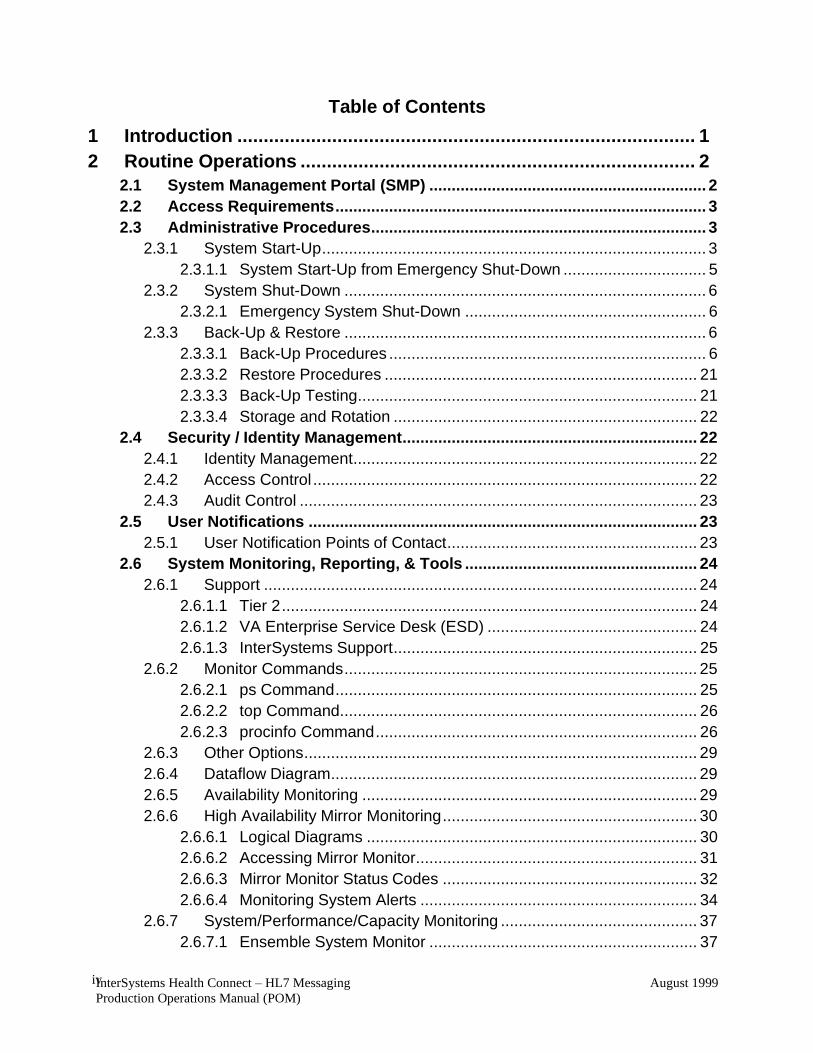
Table of Contents
1 Introduction ....................................................................................... 1
2 Routine Operations ........................................................................... 2
2.1 System Management Portal (SMP) .............................................................. 2
2.2 Access Requirements ................................................................................... 3
2.3 Administrative Procedures ........................................................................... 3
2.3.1 System Start-Up ...................................................................................... 3
2.3.1.1 System Start-Up from Emergency Shut-Down ................................ 5
2.3.2 System Shut-Down ................................................................................. 6
2.3.2.1 Emergency System Shut-Down ...................................................... 6
2.3.3 Back-Up & Restore ................................................................................. 6
2.3.3.1 Back-Up Procedures ....................................................................... 6
2.3.3.2 Restore Procedures ...................................................................... 21
2.3.3.3 Back-Up Testing ............................................................................ 21
2.3.3.4 Storage and Rotation .................................................................... 22
2.4 Security / Identity Management .................................................................. 22
2.4.1 Identity Management ............................................................................. 22
2.4.2 Access Control ...................................................................................... 22
2.4.3 Audit Control ......................................................................................... 23
2.5 User Notifications ....................................................................................... 23
2.5.1 User Notification Points of Contact ........................................................ 23
2.6 System Monitoring, Reporting, & Tools .................................................... 24
2.6.1 Support ................................................................................................. 24
2.6.1.1 Tier 2 ............................................................................................. 24
2.6.1.2 VA Enterprise Service Desk (ESD) ............................................... 24
2.6.1.3 InterSystems Support .................................................................... 25
2.6.2 Monitor Commands ............................................................................... 25
2.6.2.1 ps Command ................................................................................. 25
2.6.2.2 top Command ................................................................................ 26
2.6.2.3 procinfo Command ........................................................................ 26
2.6.3 Other Options ........................................................................................ 29
2.6.4 Dataflow Diagram .................................................................................. 29
2.6.5 Availability Monitoring ........................................................................... 29
2.6.6 High Availability Mirror Monitoring ......................................................... 30
2.6.6.1 Logical Diagrams .......................................................................... 30
2.6.6.2 Accessing Mirror Monitor ............................................................... 31
2.6.6.3 Mirror Monitor Status Codes ......................................................... 32
2.6.6.4 Monitoring System Alerts .............................................................. 34
2.6.7 System/Performance/Capacity Monitoring ............................................ 37
2.6.7.1 Ensemble System Monitor ............................................................ 37

InterSystems Health Connect – HL7 Messaging
Production Operations Manual (POM)
August 1999
v
2.6.7.2 ^Buttons ........................................................................................ 40
2.6.7.3 ^pButtons ...................................................................................... 41
2.6.7.4 cstat .............................................................................................. 43
2.6.7.5 mgstat ........................................................................................... 44
2.6.8 Critical Metrics ...................................................................................... 45
2.6.8.1 Ensemble System Monitor ............................................................ 45
2.6.8.2 Ensemble Production Monitor ....................................................... 47
2.6.8.3 Normal Daily Task Management ................................................... 47
2.6.8.4 System Console Log ..................................................................... 48
2.6.8.5 Application Error Logs ................................................................... 48
2.7 Routine Updates, Extracts, and Purges .................................................... 49
2.7.1 Purge Management Data ...................................................................... 49
2.7.1.1 Ensemble Message Purging ......................................................... 49
2.7.1.2 Purge Journal Files ....................................................................... 50
2.7.1.3 Purge Audit Database ................................................................... 51
2.7.1.4 Purge Task .................................................................................... 51
2.7.1.5 Purge Error and Log Files ............................................................. 51
2.8 Scheduled Maintenance ............................................................................. 52
2.8.1 Switch Journaling Back from AltJournal to Journal ............................... 52
2.9 Capacity Planning ....................................................................................... 53
2.9.1 Initial Capacity Plan ............................................................................... 53
3 Exception Handling ......................................................................... 54
3.1 Routine Errors ............................................................................................. 54
3.1.1 Security Errors ...................................................................................... 54
3.1.2 Time-Outs ............................................................................................. 54
3.1.3 Concurrency .......................................................................................... 55
3.2 Significant Errors ........................................................................................ 55
3.2.1 Application Error Logs ........................................................................... 55
3.2.2 Application Error Codes and Descriptions ............................................. 56
3.2.3 Infrastructure Errors .............................................................................. 57
3.2.3.1 Database ....................................................................................... 57
3.2.3.2 Web Server ................................................................................... 57
3.2.3.3 Application Server ......................................................................... 57
3.2.3.4 Network ......................................................................................... 58
3.2.3.5 Authentication & Authorization ...................................................... 58
3.2.3.6 Logical and Physical Descriptions ................................................. 58
3.3 Dependent System(s).................................................................................. 58
3.4 Troubleshooting .......................................................................................... 58
3.5 System Recovery ........................................................................................ 58
3.5.1 Manually Initiate a HealthShare Mirror Failover .................................... 59
InterSystems Health Connect – HL7 Messaging
Production Operations Manual (POM)
August 1999
vi
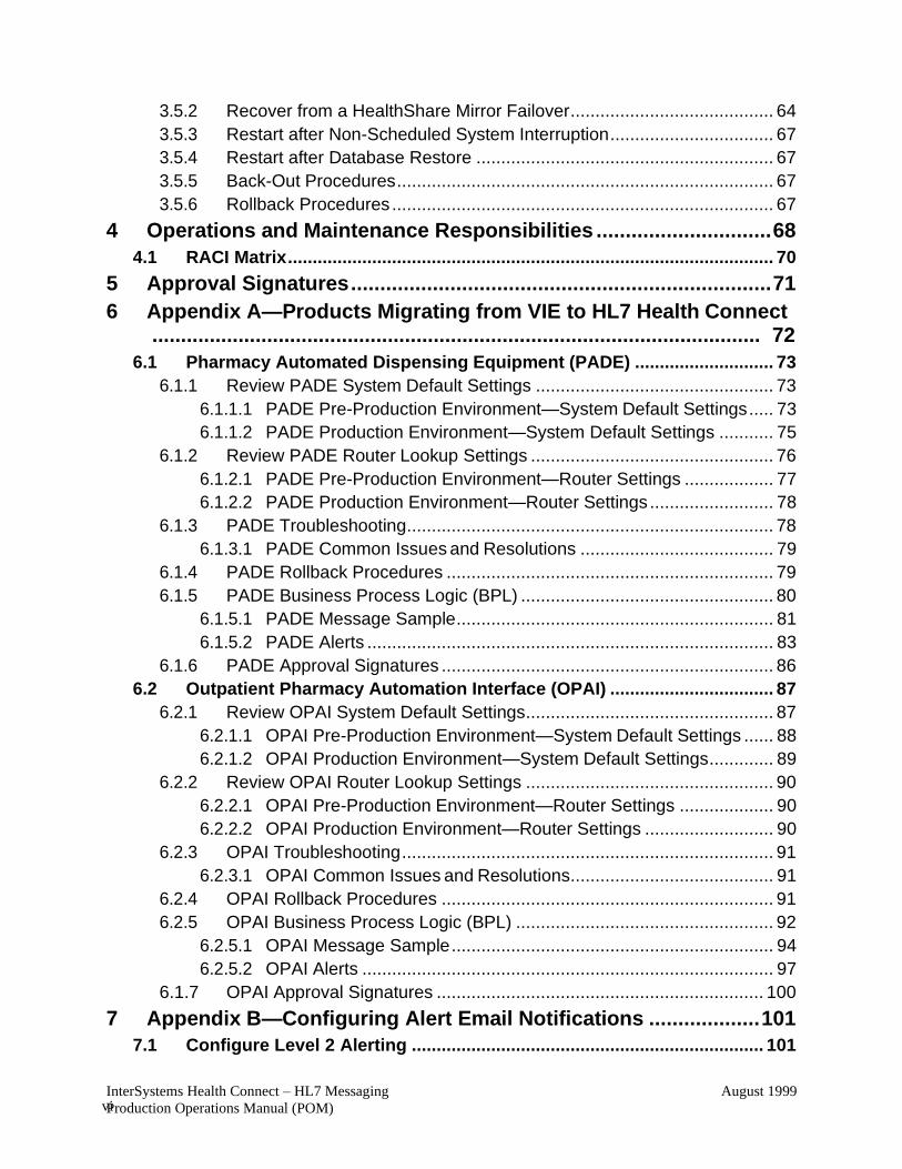
3.5.2 Recover from a HealthShare Mirror Failover ......................................... 64
3.5.3 Restart after Non-Scheduled System Interruption ................................. 67
3.5.4 Restart after Database Restore ............................................................ 67
3.5.5 Back-Out Procedures ............................................................................ 67
3.5.6 Rollback Procedures ............................................................................. 67
4 Operations and Maintenance Responsibilities .............................. 68
4.1 RACI Matrix .................................................................................................. 70
5 Approval Signatures ........................................................................ 71
6 Appendix A—Products Migrating from VIE to HL7 Health Connect .......................................................................................................... 72
6.1 Pharmacy Automated Dispensing Equipment (PADE) ............................ 73
6.1.1 Review PADE System Default Settings ................................................ 73
6.1.1.1 PADE Pre-Production Environment—System Default Settings ..... 73
6.1.1.2 PADE Production Environment—System Default Settings ........... 75
6.1.2 Review PADE Router Lookup Settings ................................................. 76
6.1.2.1 PADE Pre-Production Environment—Router Settings .................. 77
6.1.2.2 PADE Production Environment—Router Settings ......................... 78
6.1.3 PADE Troubleshooting .......................................................................... 78
6.1.3.1 PADE Common Issues and Resolutions ....................................... 79
6.1.4 PADE Rollback Procedures .................................................................. 79
6.1.5 PADE Business Process Logic (BPL) ................................................... 80
6.1.5.1 PADE Message Sample ................................................................ 81
6.1.5.2 PADE Alerts .................................................................................. 83
6.1.6 PADE Approval Signatures ................................................................... 86
6.2 Outpatient Pharmacy Automation Interface (OPAI) ................................. 87
6.2.1 Review OPAI System Default Settings .................................................. 87
6.2.1.1 OPAI Pre-Production Environment—System Default Settings ...... 88
6.2.1.2 OPAI Production Environment—System Default Settings ............. 89
6.2.2 Review OPAI Router Lookup Settings .................................................. 90
6.2.2.1 OPAI Pre-Production Environment—Router Settings ................... 90
6.2.2.2 OPAI Production Environment—Router Settings .......................... 90
6.2.3 OPAI Troubleshooting ........................................................................... 91
6.2.3.1 OPAI Common Issues and Resolutions ......................................... 91
6.2.4 OPAI Rollback Procedures ................................................................... 91
6.2.5 OPAI Business Process Logic (BPL) .................................................... 92
6.2.5.1 OPAI Message Sample ................................................................. 94
6.2.5.2 OPAI Alerts ................................................................................... 97
6.1.7 OPAI Approval Signatures .................................................................. 100
7 Appendix B—Configuring Alert Email Notifications ................... 101
7.1 Configure Level 2 Alerting ....................................................................... 101
InterSystems Health Connect – HL7 Messaging
Production Operations Manual (POM)
August 1999
vii
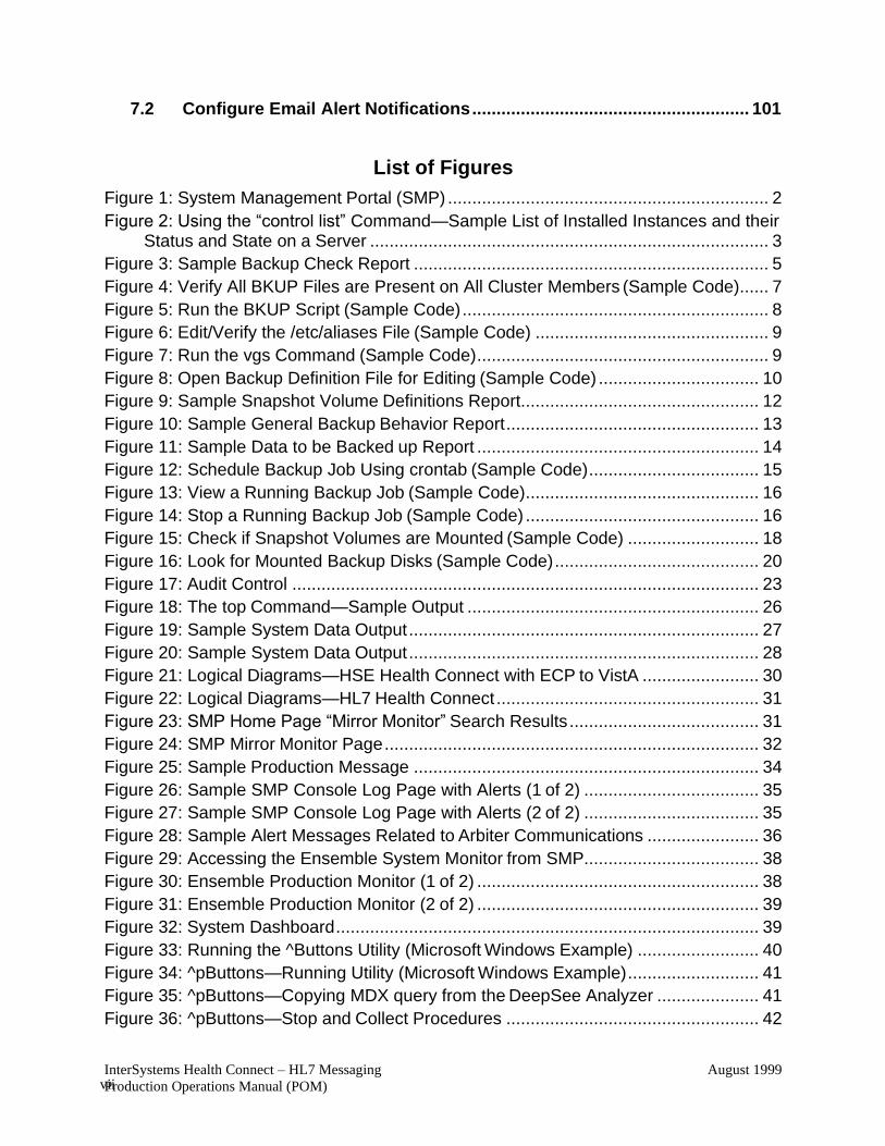
7.2 Configure Email Alert Notifications ......................................................... 101
List of Figures
Figure 1: System Management Portal (SMP) .................................................................. 2
Figure 2: Using the “control list” Command—Sample List of Installed Instances and their Status and State on a Server .................................................................................. 3
Figure 3: Sample Backup Check Report ......................................................................... 5
Figure 4: Verify All BKUP Files are Present on All Cluster Members (Sample Code) ...... 7
Figure 5: Run the BKUP Script (Sample Code) ............................................................... 8
Figure 6: Edit/Verify the /etc/aliases File (Sample Code) ................................................ 9
Figure 7: Run the vgs Command (Sample Code) ............................................................ 9
Figure 8: Open Backup Definition File for Editing (Sample Code) ................................. 10
Figure 9: Sample Snapshot Volume Definitions Report ................................................. 12
Figure 10: Sample General Backup Behavior Report .................................................... 13
Figure 11: Sample Data to be Backed up Report .......................................................... 14
Figure 12: Schedule Backup Job Using crontab (Sample Code) ................................... 15
Figure 13: View a Running Backup Job (Sample Code) ................................................ 16
Figure 14: Stop a Running Backup Job (Sample Code) ................................................ 16
Figure 15: Check if Snapshot Volumes are Mounted (Sample Code) ........................... 18
Figure 16: Look for Mounted Backup Disks (Sample Code) .......................................... 20
Figure 17: Audit Control ................................................................................................ 23
Figure 18: The top Command—Sample Output ............................................................ 26
Figure 19: Sample System Data Output ........................................................................ 27
Figure 20: Sample System Data Output ........................................................................ 28
Figure 21: Logical Diagrams—HSE Health Connect with ECP to VistA ........................ 30
Figure 22: Logical Diagrams—HL7 Health Connect ...................................................... 31
Figure 23: SMP Home Page “Mirror Monitor” Search Results ....................................... 31
Figure 24: SMP Mirror Monitor Page ............................................................................. 32
Figure 25: Sample Production Message ....................................................................... 34
Figure 26: Sample SMP Console Log Page with Alerts (1 of 2) .................................... 35
Figure 27: Sample SMP Console Log Page with Alerts (2 of 2) .................................... 35
Figure 28: Sample Alert Messages Related to Arbiter Communications ....................... 36
Figure 29: Accessing the Ensemble System Monitor from SMP.................................... 38
Figure 30: Ensemble Production Monitor (1 of 2) .......................................................... 38
Figure 31: Ensemble Production Monitor (2 of 2) .......................................................... 39
Figure 32: System Dashboard ....................................................................................... 39
Figure 33: Running the ^Buttons Utility (Microsoft Windows Example) ......................... 40
Figure 34: ^pButtons—Running Utility (Microsoft Windows Example) ........................... 41
Figure 35: ^pButtons—Copying MDX query from the DeepSee Analyzer ..................... 41
Figure 36: ^pButtons—Stop and Collect Procedures .................................................... 42
InterSystems Health Connect – HL7 Messaging
Production Operations Manual (POM)
August 1999 viii
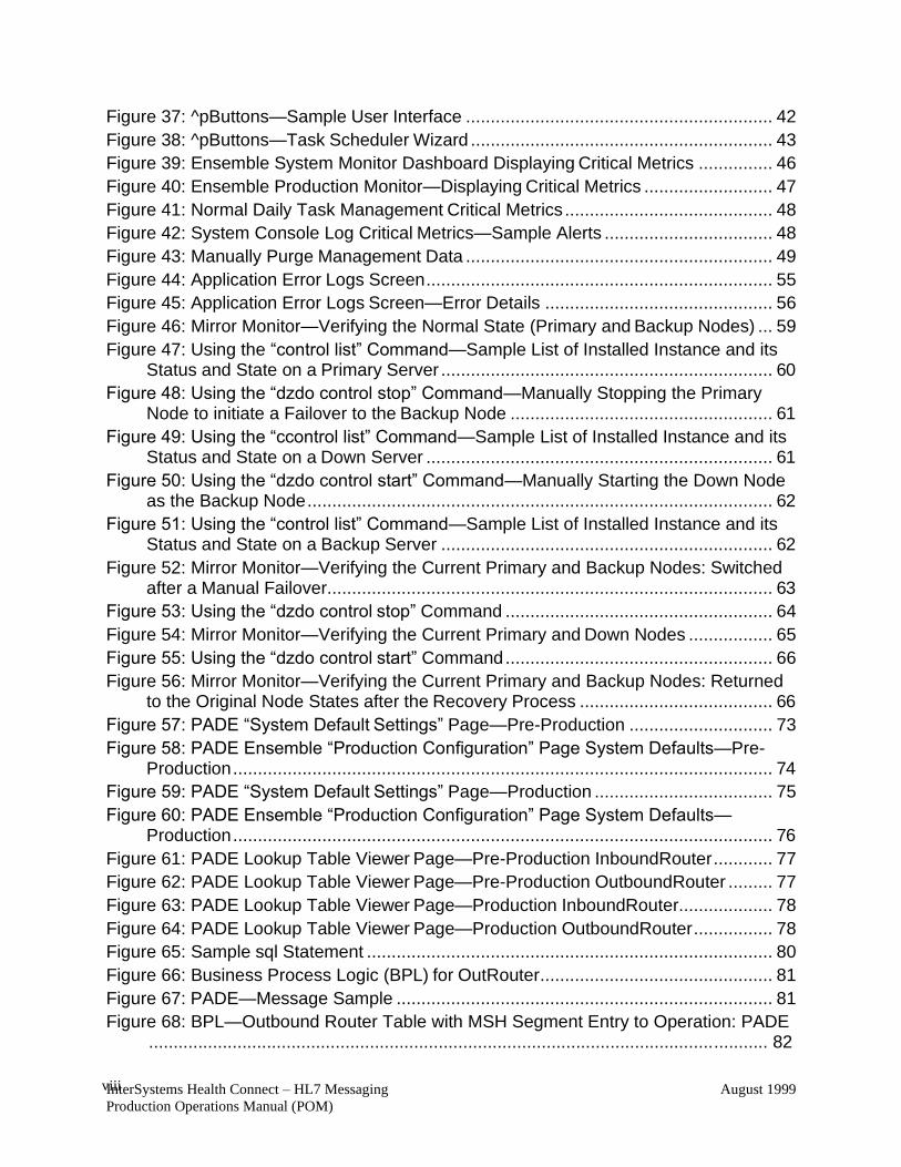
Figure 37: ^pButtons—Sample User Interface .............................................................. 42
Figure 38: ^pButtons—Task Scheduler Wizard ............................................................. 43
Figure 39: Ensemble System Monitor Dashboard Displaying Critical Metrics ............... 46
Figure 40: Ensemble Production Monitor—Displaying Critical Metrics .......................... 47
Figure 41: Normal Daily Task Management Critical Metrics .......................................... 48
Figure 42: System Console Log Critical Metrics—Sample Alerts .................................. 48
Figure 43: Manually Purge Management Data .............................................................. 49
Figure 44: Application Error Logs Screen ...................................................................... 55
Figure 45: Application Error Logs Screen—Error Details .............................................. 56
Figure 46: Mirror Monitor—Verifying the Normal State (Primary and Backup Nodes) ... 59
Figure 47: Using the “control list” Command—Sample List of Installed Instance and its Status and State on a Primary Server ................................................................... 60
Figure 48: Using the “dzdo control stop” Command—Manually Stopping the Primary Node to initiate a Failover to the Backup Node ..................................................... 61
Figure 49: Using the “ccontrol list” Command—Sample List of Installed Instance and its Status and State on a Down Server ...................................................................... 61
Figure 50: Using the “dzdo control start” Command—Manually Starting the Down Node as the Backup Node .............................................................................................. 62
Figure 51: Using the “control list” Command—Sample List of Installed Instance and its Status and State on a Backup Server ................................................................... 62
Figure 52: Mirror Monitor—Verifying the Current Primary and Backup Nodes: Switched after a Manual Failover .......................................................................................... 63
Figure 53: Using the “dzdo control stop” Command ...................................................... 64
Figure 54: Mirror Monitor—Verifying the Current Primary and Down Nodes ................. 65
Figure 55: Using the “dzdo control start” Command ...................................................... 66
Figure 56: Mirror Monitor—Verifying the Current Primary and Backup Nodes: Returned to the Original Node States after the Recovery Process ....................................... 66
Figure 57: PADE “System Default Settings” Page—Pre-Production ............................. 73
Figure 58: PADE Ensemble “Production Configuration” Page System Defaults—Pre- Production ............................................................................................................. 74
Figure 59: PADE “System Default Settings” Page—Production .................................... 75
Figure 60: PADE Ensemble “Production Configuration” Page System Defaults— Production ............................................................................................................. 76
Figure 61: PADE Lookup Table Viewer Page—Pre-Production InboundRouter ............ 77
Figure 62: PADE Lookup Table Viewer Page—Pre-Production OutboundRouter ......... 77
Figure 63: PADE Lookup Table Viewer Page—Production InboundRouter................... 78
Figure 64: PADE Lookup Table Viewer Page—Production OutboundRouter ................ 78
Figure 65: Sample sql Statement .................................................................................. 80
Figure 66: Business Process Logic (BPL) for OutRouter ............................................... 81
Figure 67: PADE—Message Sample ............................................................................ 81
Figure 68: BPL—Outbound Router Table with MSH Segment Entry to Operation: PADE .............................................................................................................................. 82
InterSystems Health Connect – HL7 Messaging
Production Operations Manual (POM)
August 1999 ix
Figure 69: BPL—Enabled Operation 999.PADE.Server ................................................ 82
Figure 70: PADE—Alerts: Automatically Resent HL7 Message: Operations List showing PADE Server with Purple Indicator (Retrying) ....................................................... 84
Figure 71: HL7 Health Connect—Production Configuration Legend: Status Indicators 85
Figure 72: OPAI “System Default Settings” Page—Pre-Production ............................... 88
Figure 73: OPAI Ensemble “Production Configuration” Page System Defaults—Pre- Production ............................................................................................................. 89
Figure 74: OPAI “System Default Settings” Page—Production ..................................... 89
Figure 75: OPAI Ensemble “Production Configuration” Page System Defaults— Production ............................................................................................................. 89
Figure 76: OPAI Lookup Table Viewer Page—Pre-Production InboundRouter ............. 90
Figure 77: OPAI Lookup Table Viewer Page—Pre-Production OutboundRouter .......... 90
Figure 78: OPAI Lookup Table Viewer Page—Production InboundRouter .................... 90
Figure 79: OPAI Lookup Table Viewer Page—Production OutboundRouter ................. 90
Figure 80: Sample sql Statement .................................................................................. 92
Figure 81: Business Process Logic (BPL) for OutRouter ............................................... 93
Figure 82: OPAI—Message Sample ............................................................................. 94
Figure 83: BPL—Outbound Router Table with MSH Segment Entry to Operation: OPAI ..................................................................................................................... 97
Figure 84: BPL—Enabled Operation To_OPAI640_Parata_9025 ................................. 97
Figure 85: OPAI—Alerts: Automatically Resent HL7 Message: Operations List showing OPAI Server with Purple Indicator (Retrying) ........................................................ 98
Figure 86: HL7 Health Connect—Production Configuration Legend: Status Indicators 99
Figure 87: Choose Alert Level for Alert Notifications ................................................... 101
Figure 88: Configure Email Alert Notifications ............................................................. 103
List of Tables
Table 1: Mirror Monitor Status Codes ............................................................................ 32
Table 2: Ensemble Throughput Critical Metrics ............................................................. 45
Table 3: System Time Critical Metrics ........................................................................... 45
Table 4: Errors and Alerts Critical Metrics ..................................................................... 46
Table 5: Task Manager Critical Metrics ......................................................................... 46
Table 6: HL7 Health Connect—Operations and Maintenance Responsibilities ............. 68
Table 7: PADE—Common Issues and Resolutions ....................................................... 79
Table 8: PADE—Alerts .................................................................................................. 83
Table 9: OPAI System IP Addresses/DNS—Pre-Production ......................................... 88
Table 10: OPAI System IP Addresses/DNS—Production (will be updated once in production) ............................................................................................................ 89
Table 11: OPAI—Common Issues and Resolutions ...................................................... 91
Table 12: OPAI—Alerts ................................................................................................. 97
InterSystems Health Connect – HL7 Messaging
Production Operations Manual (POM)
August 1999 x
Table 13: Manage Email Options Menu Options ......................................................... 102
InterSystems Health Connect – HL7 Messaging
Production Operations Manual (POM)
August 1999
1
1 Introduction This Production Operations Manual (POM) describes how to maintain the components of the
InterSystems Health Level Seven (HL7) Health Connect (HC) messaging system. It also
describes how to troubleshoot problems that might occur with this system in production. The
intended audience for this document is the Office of Information and Technology (OIT) teams
responsible for hosting and maintaining the system after production release. This document is
normally finalized just prior to production release, and includes many updated elements specific
to the hosting environment.
InterSystems has an Enterprise Service Bus (ESB) product called Health Connect (HC):
• Health Level Seven (HL7) Health Connect—Includes projects above the line (e.g., PADE
and OPAI).
• HealthShare Enterprise (HSE) Health Connect—Pushes data from Veterans Health
Information Systems and Technology Architecture (VistA) into Health Connect.
Health Connect provides the following capabilities:
• HL7 Messaging between VistA and VAMC Local Devices in all Regions.
• HL7 Messaging between VistA instances (intra Region and between Regions).
• HSE VistA data feeds between the national HSE instances (HSE-AITC, HSE-PITC, and
HSE-Cloud) and the regional Health Connect instances.
Electronic Health Record Modernization (EHRM) is currently deploying the initial HC
capability into each of the VA regional data centers with a HealthShare Enterprise (HSE)
capability in the VA enterprise data centers.
HealthShare Enterprise Platform (HSEP) Health Connect instance pairs are expanded to all VA
Regional Data Centers (RDCs) enabling HL7 messaging for other applications (e.g., PADE and
OPAI) in all regions.
Primary Health Connect pairs (for HL7 messaging and HSE VistA data feeds) are deployed to all
regions to align with production VistA instances in both RDC pairs.
NOTE: This POM describes the functionality, utilities, and options available with the
HL7 Health Connect system.
InterSystems Health Connect – HL7 Messaging
Production Operations Manual (POM)
August 1999
2
2 Routine Operations This section describes, at a high-level, what is required of an operator/administrator or other non-
business user to maintain the system at an operational and accessible state.
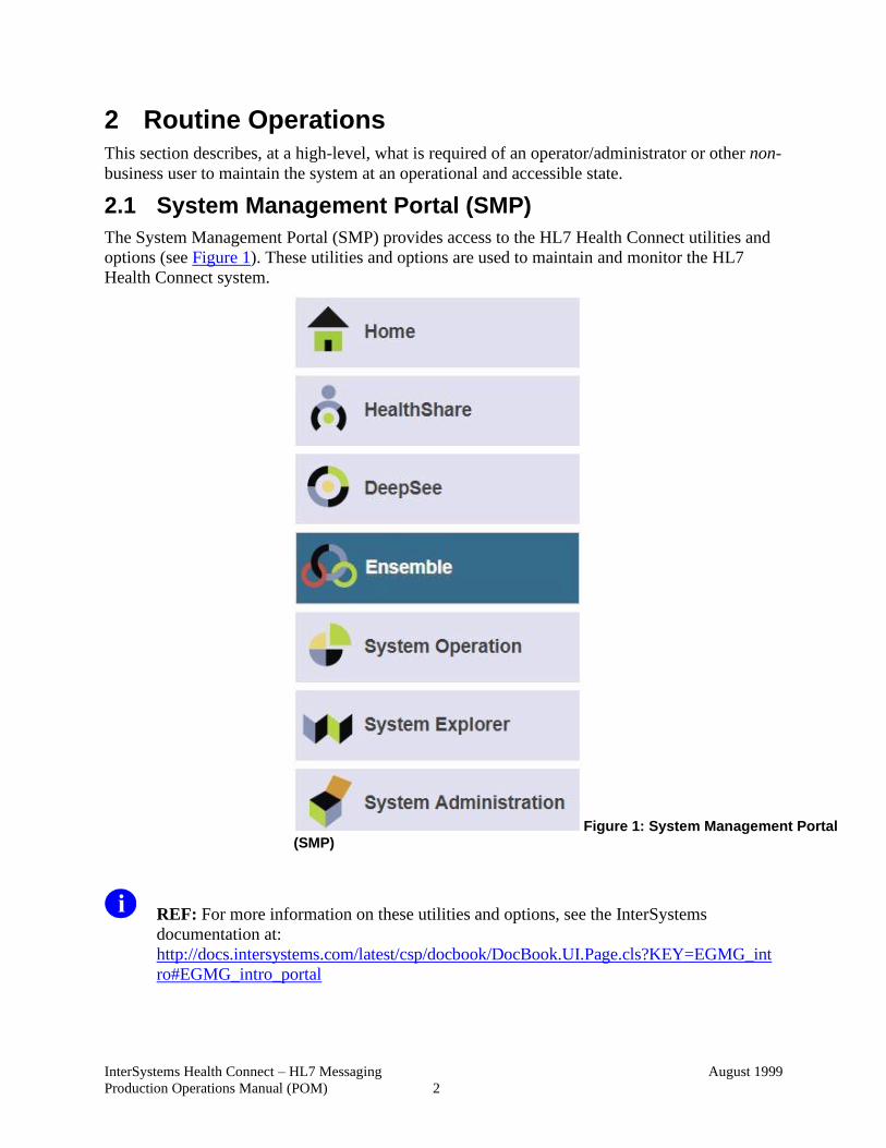
2.1 System Management Portal (SMP)
The System Management Portal (SMP) provides access to the HL7 Health Connect utilities and
options (see Figure 1). These utilities and options are used to maintain and monitor the HL7
Health Connect system.
Figure 1: System Management Portal (SMP)
REF: For more information on these utilities and options, see the InterSystems
documentation at:
http://docs.intersystems.com/latest/csp/docbook/DocBook.UI.Page.cls?KEY=EGMG_int
ro#EGMG_intro_portal
InterSystems Health Connect – HL7 Messaging
Production Operations Manual (POM)
August 1999
3
Specifically, for more information on the Ensemble System Monitor:
http://docs.intersystems.com/latest/csp/docbook/DocBook.UI.Page.cls?KEY=EMONITO
R_all
NOTE: Use of the SMP is referred to throughout this document.
2.2 Access Requirements
It is important to note that all users who maintain and monitor the HL7 Health Connect system
must have System Administrator level access with elevated privileges.
2.3 Administrative Procedures
2.3.1 System Start-Up
This section describes how to start the Health Connect system on Linux and bring it to an
operational state.
To start Health Connect, do the following:
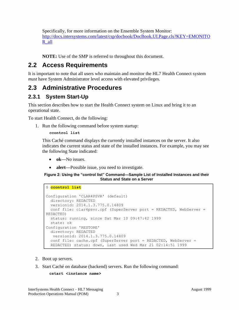
1. Run the following command before system startup:
ccontrol list
This Caché command displays the currently installed instances on the server. It also
indicates the current status and state of the installed instances. For example, you may see
the following State indicated:
• ok—No issues.
• alert—Possible issue, you need to investigate.
Figure 2: Using the “control list” Command—Sample List of Installed Instances and their Status and State on a Server
2. Boot up servers.
3. Start Caché on database (backend) servers. Run the following command:
cstart <instance name>
$ ccontrol list
Configuration 'CLAR4PSVR' (default)
directory: REDACTED
versionid: 2014.1.3.775.0.14809
conf file: clar4psvr.cpf (SuperServer port = REDACTED, WebServer =
REDACTED)
status: running, since Sat Mar 10 09:47:42 1999
state: ok
Configuration 'RESTORE'
directory: REDACTED
versionid: 2014.1.3.775.0.14809
conf file: cache.cpf (SuperServer port = REDACTED, WebServer =
REDACTED) status: down, last used Wed Mar 21 02:14:51 1999
InterSystems Health Connect – HL7 Messaging
Production Operations Manual (POM)
August 1999
4
4. Start Caché on Application servers. Run the following command:
cstart <instance name>
5. Start Health Level Seven (HL7).
6. Verify the startup was successful. Run the ccontrol list command (see Step 1) to verify
all instances show the following:
• Status: Running
• State: ok
REF: For a list of Veterans Health Information Systems and Technology Architecture
(VistA) instances by region, see the
HC_HL_App_Server_Standards_All_Regions_MASTER.xlsx Microsoft® Excel
document located at: http://go.va.gov/sxcu.
VMS Commands
The following procedure checks CACHE$LOGS:SCD_BKUP_DDMMMYYY.LOG file:
CACHE$BKUP:CHECK-BACKUP-COMPLETE.COM
This procedure checks any backups that started the previous day after 07:00. It does the
following:
1. Checks for messages that say "Warning!" Errors could be VMS errors (e.g., space
issues, -E-, -F-, devalloc, etc.), quiescence errors, and cache incremental backup errors.
2. If VMS errors are found, it checks the SCD.LOG for "D2D-E-FAILED" messages, all
other messages are non-fatal.
3. Checks for integrity errors, "ERRORS ***" and "ERROR ***".
4. Checks for "Backup failed" message, which is the failure of the cache incremental
restore.
5. If backup completely fails, there will be no log file to check, message will be printed.
6. If backup all successful, journal files older than 5 days will be deleted unless logical is
set.
REF: See DONT-DEL-OLD_JOURN.
Backup check will be submitted for the next day.
Report is mailed out at 7:00 a.m. to VMS mail list MAIL$DIST:BKUP_CHK.DIS.
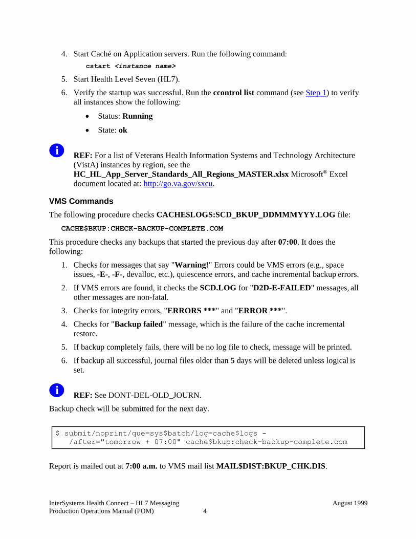
$ submit/noprint/que=sys$batch/log=cache$logs -
/after="tomorrow + 07:00" cache$bkup:check-backup-complete.com
InterSystems Health Connect – HL7 Messaging
Production Operations Manual (POM)
August 1999
5
Figure 3: Sample Backup Check Report
2.3.1.1 System Start-Up from Emergency Shut-Down
If a start-up from a power outage or emergency shut-down occurs, do the following procedures
to restart the HL7 Health Connect system:
ccontrol start $instance
REF: For a list of VistA instances by region, see the
HC_HL_App_Server_Standards_All_Regions_MASTER.xlsx Microsoft® Excel
document located at: http://go.va.gov/sxcu.
InterSystems Health Connect – HL7 Messaging
Production Operations Manual (POM)
August 1999
6
2.3.2 System Shut-Down
This section describes how to shut down the system and bring it to a non-operational state. This
procedure stops all processes and components. The end state of this procedure is a state in which
you can apply the start-up procedure.
To shut down the system, do the following:
1. Disable TCPIP services.
2. Shut down HL7.
3. Shut down TaskMan.
4. Shut down Caché Application servers.
5. Shut down Caché Database servers.
6. Shut down operating system on all servers.
To restart the HL7 Health Connect system, run the following command:
ccontrol start $instance
REF: For a list of VistA instances by region, see the
HC_HL_App_Server_Standards_All_Regions_MASTER.xlsx Microsoft® Excel
document located at: http://go.va.gov/sxcu.
2.3.2.1 Emergency System Shut-Down
This section guides personnel through the proper emergency system shutdown, which is different
from a normal system shutdown, to avoid potential file corruption or component damage.
2.3.3 Back-Up & Restore
This section is a high-level description of the system backup and restore strategy.
2.3.3.1 Back-Up Procedures
This section describes the installation of the Restore configuration and creation of the Linux files
associated with the Backup process, as well as a more in depth look at the creation and
maintenance of the site backup.dat file.
Access Required
To perform the tasks in this section, users must have root level access.
Discussion Topics
The following topics are described in this section:
• Installing Backup (rdp_bkup_setup Script)
• Maintaining Backup Parameter File (backup.dat)
• Scheduling and Managing Backups
• Monitoring Backup Process
InterSystems Health Connect – HL7 Messaging
Production Operations Manual (POM)
August 1999
7
• Monitoring Backup Log Files
2.3.3.1.1 Installing Backup (rdp_bkup_setup Script)
The installation of the Restore configuration and the backup scripts is typically done when the
site’s Caché instance is originally installed. Although this should not need to be done more than
once, the steps for the Backup installation are included below.
All backup scripts are located in the following Linux directory:
/usr/local/sbin
The rdp_bkup_setup script installs the Caché RESTORE configuration, creates backup users
and groups, and creates the backup.dat.
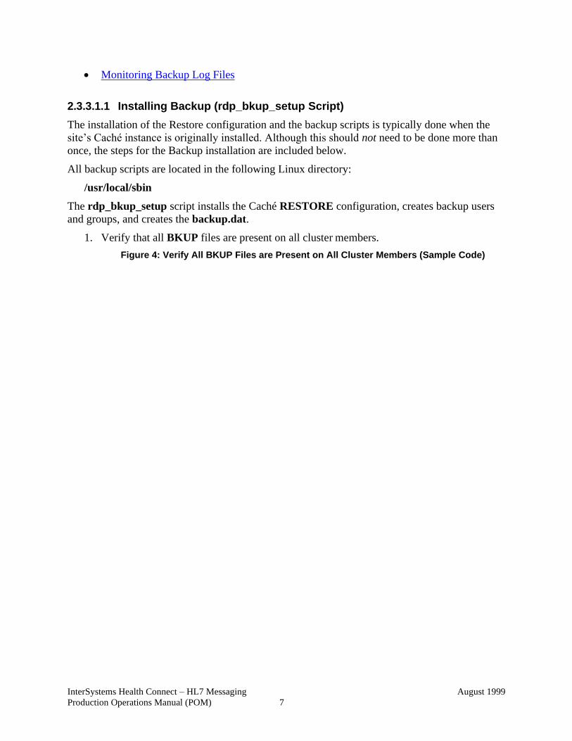
1. Verify that all BKUP files are present on all cluster members.
Figure 4: Verify All BKUP Files are Present on All Cluster Members (Sample Code)
InterSystems Health Connect – HL7 Messaging
Production Operations Manual (POM)
August 1999
8
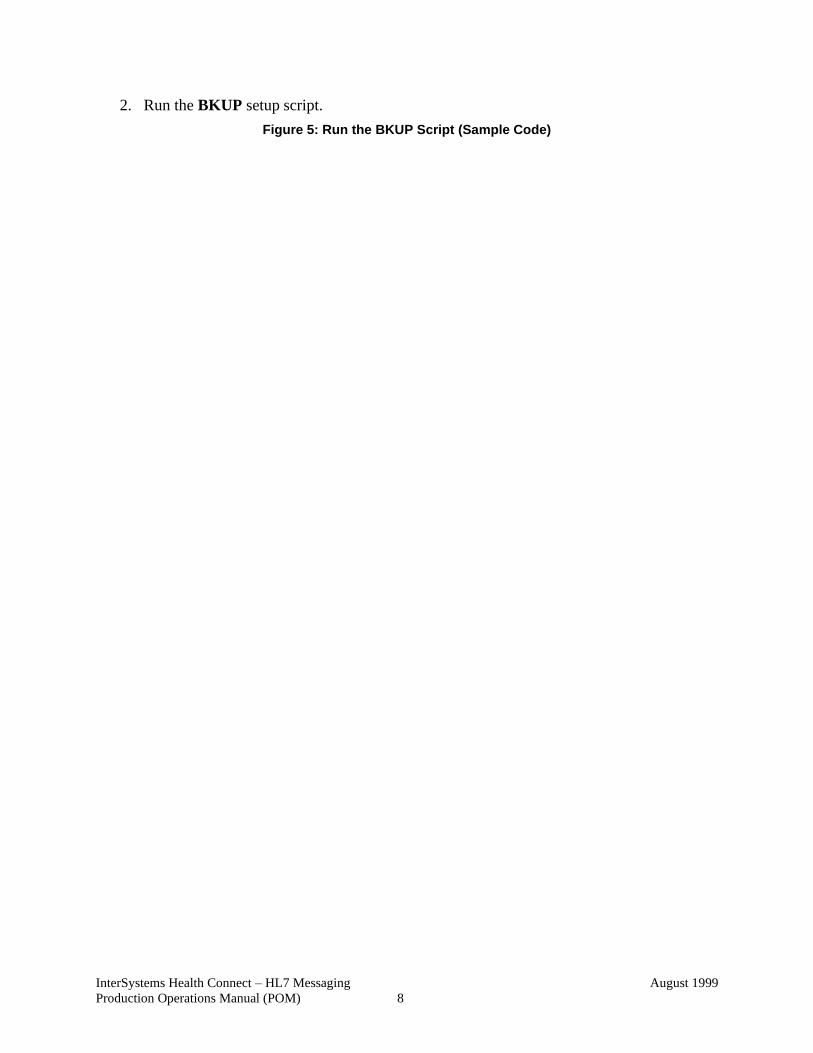
2. Run the BKUP setup script.
Figure 5: Run the BKUP Script (Sample Code)
InterSystems Health Connect – HL7 Messaging
Production Operations Manual (POM)
August 1999
9
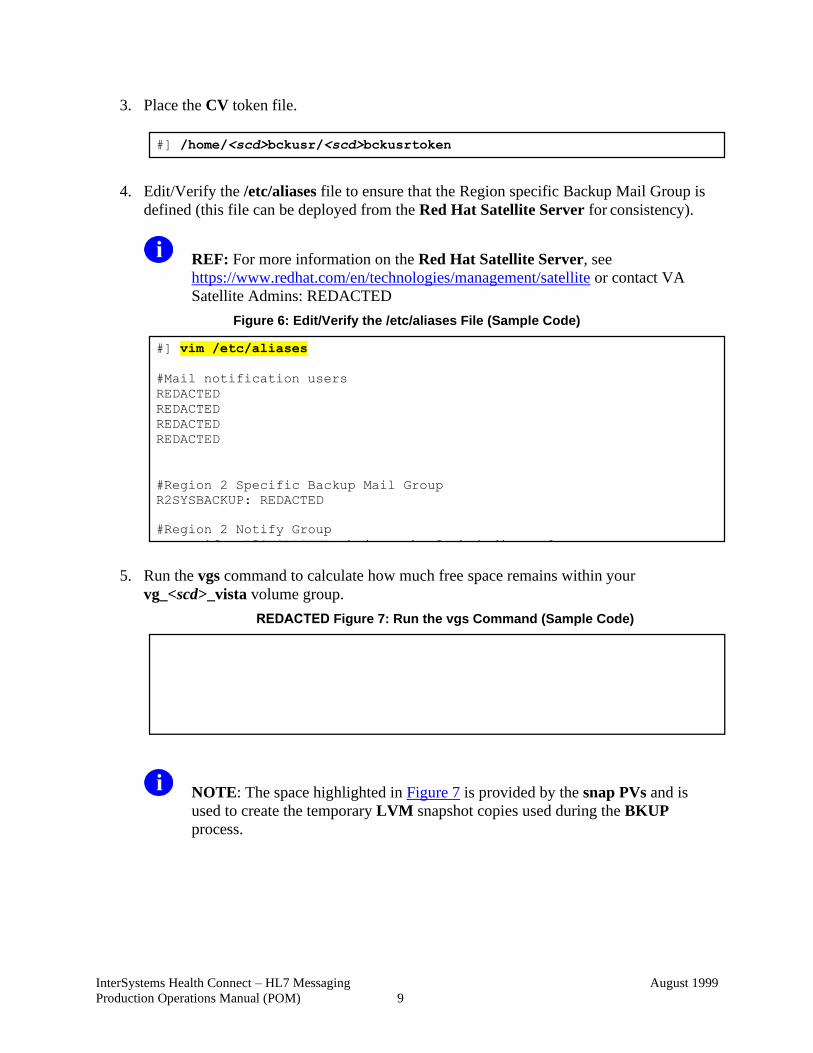
3. Place the CV token file.
4. Edit/Verify the /etc/aliases file to ensure that the Region specific Backup Mail Group is
defined (this file can be deployed from the Red Hat Satellite Server for consistency).
REF: For more information on the Red Hat Satellite Server, see
https://www.redhat.com/en/technologies/management/satellite or contact VA
Satellite Admins: REDACTED
Figure 6: Edit/Verify the /etc/aliases File (Sample Code)
5. Run the vgs command to calculate how much free space remains within your
vg_<scd>_vista volume group.
REDACTED Figure 7: Run the vgs Command (Sample Code)
NOTE: The space highlighted in Figure 7 is provided by the snap PVs and is
used to create the temporary LVM snapshot copies used during the BKUP
process.
#] /home/<scd>bckusr/<scd>bckusrtoken
#] vim /etc/aliases
#Mail notification users
REDACTED
REDACTED
REDACTED
REDACTED
#Region 2 Specific Backup Mail Group
R2SYSBACKUP: REDACTED
#Region 2 Notify Group
suxnotify: R2SYSBACKUP vhaispcochrm0 vhaisdjonesc0
InterSystems Health Connect – HL7 Messaging
Production Operations Manual (POM)
August 1999
10
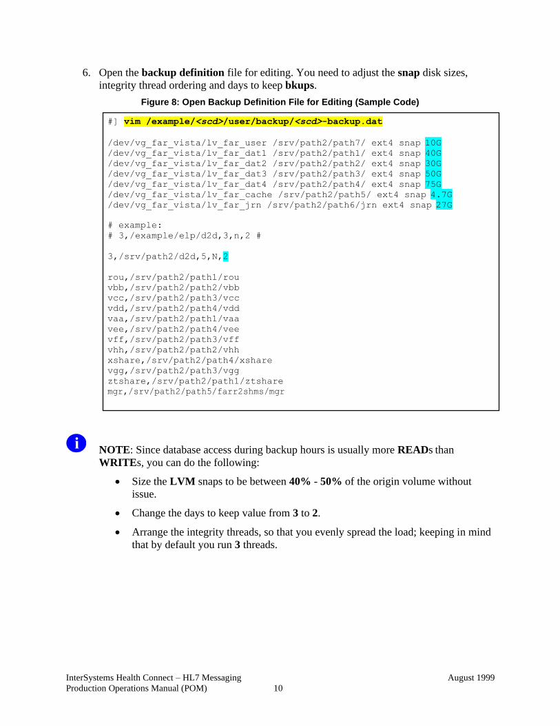
6. Open the backup definition file for editing. You need to adjust the snap disk sizes,
integrity thread ordering and days to keep bkups.
Figure 8: Open Backup Definition File for Editing (Sample Code)
NOTE: Since database access during backup hours is usually more READs than
WRITEs, you can do the following:
• Size the LVM snaps to be between 40% - 50% of the origin volume without
issue.
• Change the days to keep value from 3 to 2.
• Arrange the integrity threads, so that you evenly spread the load; keeping in mind
that by default you run 3 threads.
#] vim /example/<scd>/user/backup/<scd>-backup.dat
/dev/vg_far_vista/lv_far_user /srv/path2/path7/ ext4 snap 10G
/dev/vg_far_vista/lv_far_dat1 /srv/path2/path1/ ext4 snap 40G
/dev/vg_far_vista/lv_far_dat2 /srv/path2/path2/ ext4 snap 30G
/dev/vg_far_vista/lv_far_dat3 /srv/path2/path3/ ext4 snap 50G
/dev/vg_far_vista/lv_far_dat4 /srv/path2/path4/ ext4 snap 75G
/dev/vg_far_vista/lv_far_cache /srv/path2/path5/ ext4 snap 4.7G
/dev/vg_far_vista/lv_far_jrn /srv/path2/path6/jrn ext4 snap 27G
# example:
# 3,/example/elp/d2d,3,n,2 #
3,/srv/path2/d2d,5,N,2
rou,/srv/path2/path1/rou
vbb,/srv/path2/path2/vbb
vcc,/srv/path2/path3/vcc
vdd,/srv/path2/path4/vdd
vaa,/srv/path2/path1/vaa
vee,/srv/path2/path4/vee
vff,/srv/path2/path3/vff
vhh,/srv/path2/path2/vhh
xshare,/srv/path2/path4/xshare
vgg,/srv/path2/path3/vgg
ztshare,/srv/path2/path1/ztshare
mgr,/srv/path2/path5/farr2shms/mgr
InterSystems Health Connect – HL7 Messaging
Production Operations Manual (POM)
August 1999
11
2.3.3.1.2 Maintaining Backup Parameter File (backup.dat)
Access Level Required
To maintain the backup parameter file (i.e., backup.dat), users must have root level access.
File Location and Description
The backup.dat file is located in the following directory:
/example/<scd>/user/backup/
The original <scd>backup.dat file is created when the rdp_bkup_setup script is run.
The <scd>backup.dat file contains parameters for configuring and running the backup.
Discussion Topics
The following topics are described in this section:
• Snapshot Volume Definitions
• Defining General Backup Behavior
• Defining the Datasets for Backup and the Backup Location
InterSystems Health Connect – HL7 Messaging
Production Operations Manual (POM)
August 1999
12
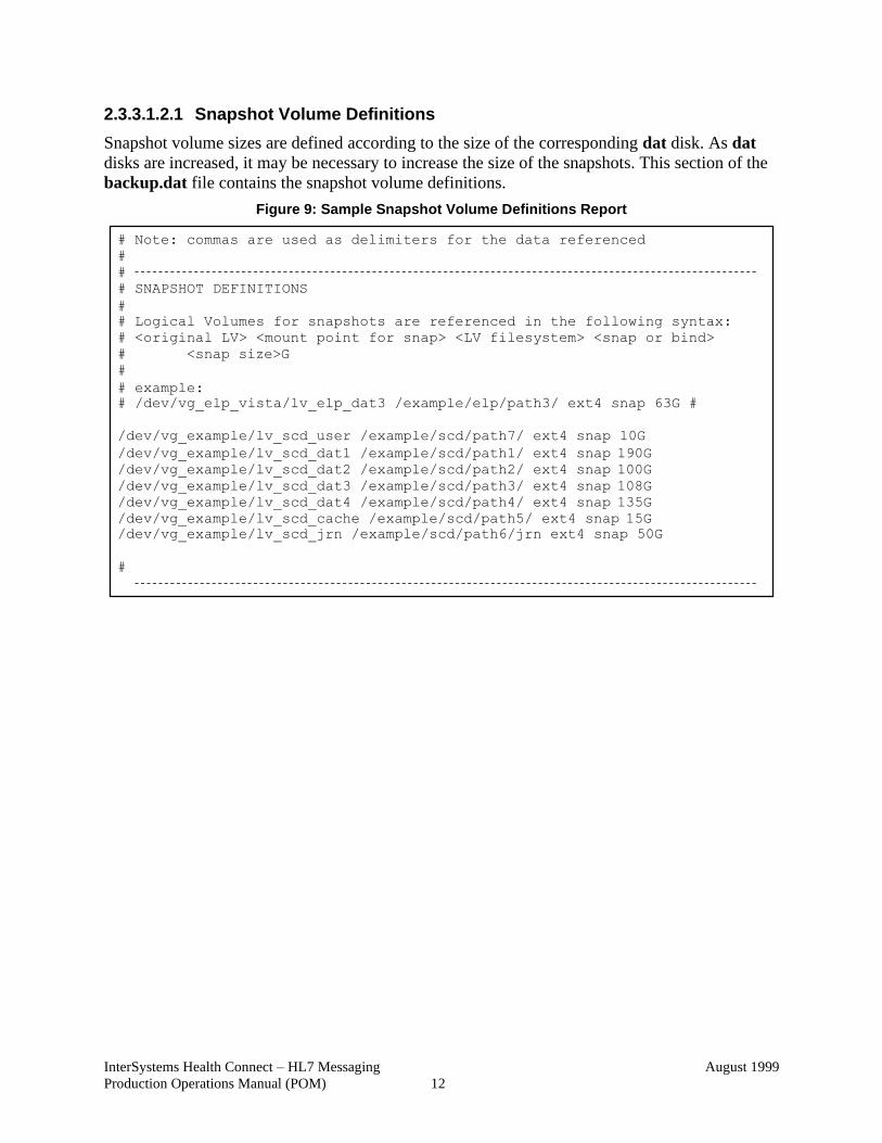
2.3.3.1.2.1 Snapshot Volume Definitions
Snapshot volume sizes are defined according to the size of the corresponding dat disk. As dat
disks are increased, it may be necessary to increase the size of the snapshots. This section of the
backup.dat file contains the snapshot volume definitions.
Figure 9: Sample Snapshot Volume Definitions Report
# Note: commas are used as delimiters for the data referenced
#
#
# SNAPSHOT DEFINITIONS
#
# Logical Volumes for snapshots are referenced in the following syntax:
# <original LV> <mount point for snap> <LV filesystem> <snap or bind>
# <snap size>G
#
# example:
# /dev/vg_elp_vista/lv_elp_dat3 /example/elp/path3/ ext4 snap 63G #
/dev/vg_example/lv_scd_user /example/scd/path7/ ext4 snap 10G
/dev/vg_example/lv_scd_dat1 /example/scd/path1/ ext4 snap 190G
/dev/vg_example/lv_scd_dat2 /example/scd/path2/ ext4 snap 100G
/dev/vg_example/lv_scd_dat3 /example/scd/path3/ ext4 snap 108G
/dev/vg_example/lv_scd_dat4 /example/scd/path4/ ext4 snap 135G
/dev/vg_example/lv_scd_cache /example/scd/path5/ ext4 snap 15G
/dev/vg_example/lv_scd_jrn /example/scd/path6/jrn ext4 snap 50G
#
InterSystems Health Connect – HL7 Messaging
Production Operations Manual (POM)
August 1999
13
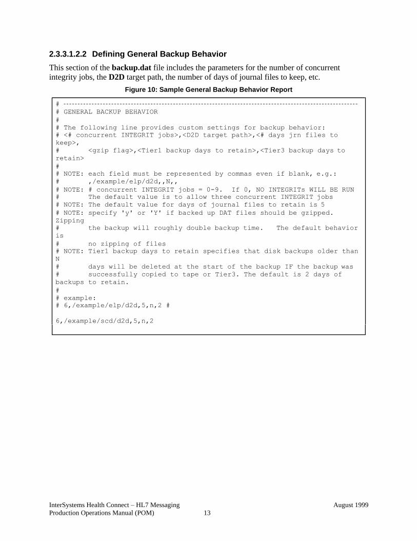
2.3.3.1.2.2 Defining General Backup Behavior
This section of the backup.dat file includes the parameters for the number of concurrent
integrity jobs, the D2D target path, the number of days of journal files to keep, etc.
Figure 10: Sample General Backup Behavior Report
#
# GENERAL BACKUP BEHAVIOR
#
# The following line provides custom settings for backup behavior:
# <# concurrent INTEGRIT jobs>,<D2D target path>,<# days jrn files to
keep>,
# <gzip flag>,<Tier1 backup days to retain>,<Tier3 backup days to
retain>
#
# NOTE: each field must be represented by commas even if blank, e.g.:
# ,/example/elp/d2d,,N,,
# NOTE: # concurrent INTEGRIT jobs = 0-9. If 0, NO INTEGRITs WILL BE RUN
# The default value is to allow three concurrent INTEGRIT jobs
# NOTE: The default value for days of journal files to retain is 5
# NOTE: specify 'y' or 'Y' if backed up DAT files should be gzipped.
Zipping
# the backup will roughly double backup time. The default behavior
is
# no zipping of files
# NOTE: Tier1 backup days to retain specifies that disk backups older than
N
# days will be deleted at the start of the backup IF the backup was
# successfully copied to tape or Tier3. The default is 2 days of
backups to retain.
#
# example:
# 6,/example/elp/d2d,5,n,2 #
6,/example/scd/d2d,5,n,2
InterSystems Health Connect – HL7 Messaging
Production Operations Manual (POM)
August 1999
14
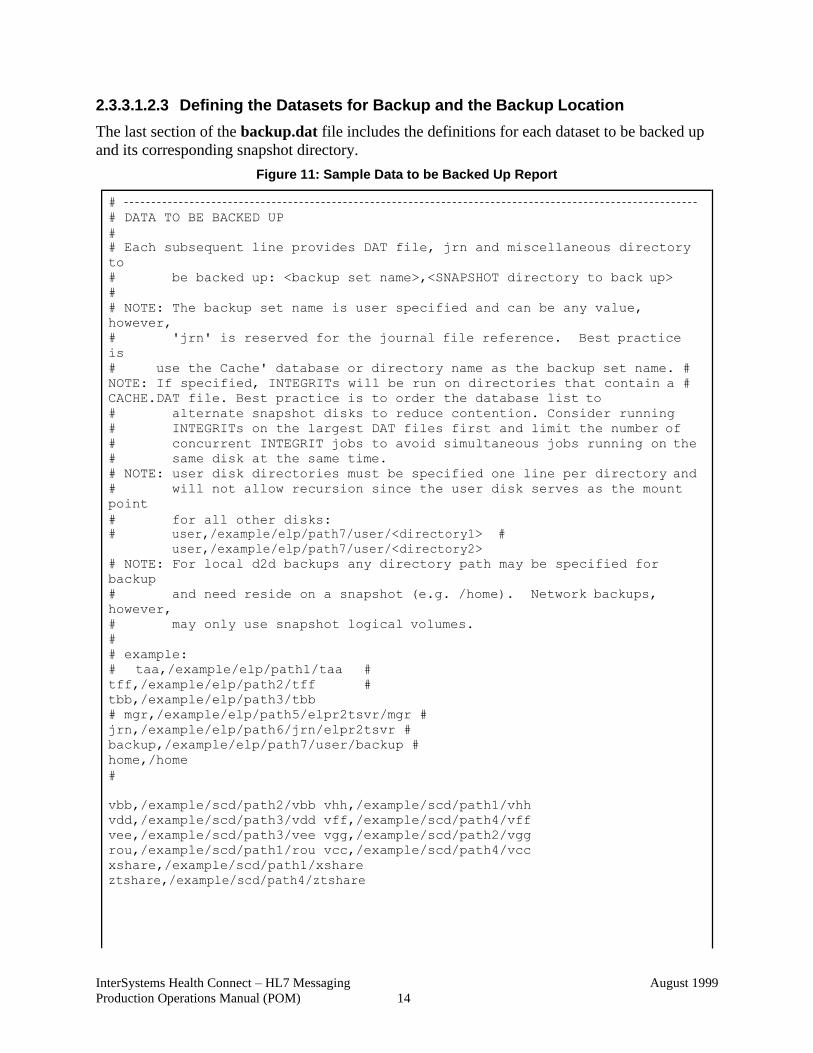
2.3.3.1.2.3 Defining the Datasets for Backup and the Backup Location
The last section of the backup.dat file includes the definitions for each dataset to be backed up
and its corresponding snapshot directory.
Figure 11: Sample Data to be Backed Up Report
#
# DATA TO BE BACKED UP
#
# Each subsequent line provides DAT file, jrn and miscellaneous directory
to
# be backed up: <backup set name>,<SNAPSHOT directory to back up>
#
# NOTE: The backup set name is user specified and can be any value,
however,
# 'jrn' is reserved for the journal file reference. Best practice
is
# use the Cache' database or directory name as the backup set name. #
NOTE: If specified, INTEGRITs will be run on directories that contain a #
CACHE.DAT file. Best practice is to order the database list to
# alternate snapshot disks to reduce contention. Consider running
# INTEGRITs on the largest DAT files first and limit the number of
# concurrent INTEGRIT jobs to avoid simultaneous jobs running on the
# same disk at the same time.
# NOTE: user disk directories must be specified one line per directory and
# will not allow recursion since the user disk serves as the mount
point
# for all other disks:
# user,/example/elp/path7/user/<directory1> #
user,/example/elp/path7/user/<directory2>
# NOTE: For local d2d backups any directory path may be specified for
backup
# and need reside on a snapshot (e.g. /home). Network backups,
however,
# may only use snapshot logical volumes.
#
# example:
# taa,/example/elp/path1/taa #
tff,/example/elp/path2/tff #
tbb,/example/elp/path3/tbb
# mgr,/example/elp/path5/elpr2tsvr/mgr #
jrn,/example/elp/path6/jrn/elpr2tsvr #
backup,/example/elp/path7/user/backup #
home,/home
#
vbb,/example/scd/path2/vbb vhh,/example/scd/path1/vhh
vdd,/example/scd/path3/vdd vff,/example/scd/path4/vff
vee,/example/scd/path3/vee vgg,/example/scd/path2/vgg
rou,/example/scd/path1/rou vcc,/example/scd/path4/vcc
xshare,/example/scd/path1/xshare
ztshare,/example/scd/path4/ztshare
InterSystems Health Connect – HL7 Messaging
Production Operations Manual (POM)
August 1999
15
2.3.3.1.3 Scheduling and Managing Backups
Discussion Topics
The following topics are described in this section:
• Schedule Backup Job Using crontab
• Running a Backup Job on Demand
• View Running Backup Job
• Stop Running Backup Job
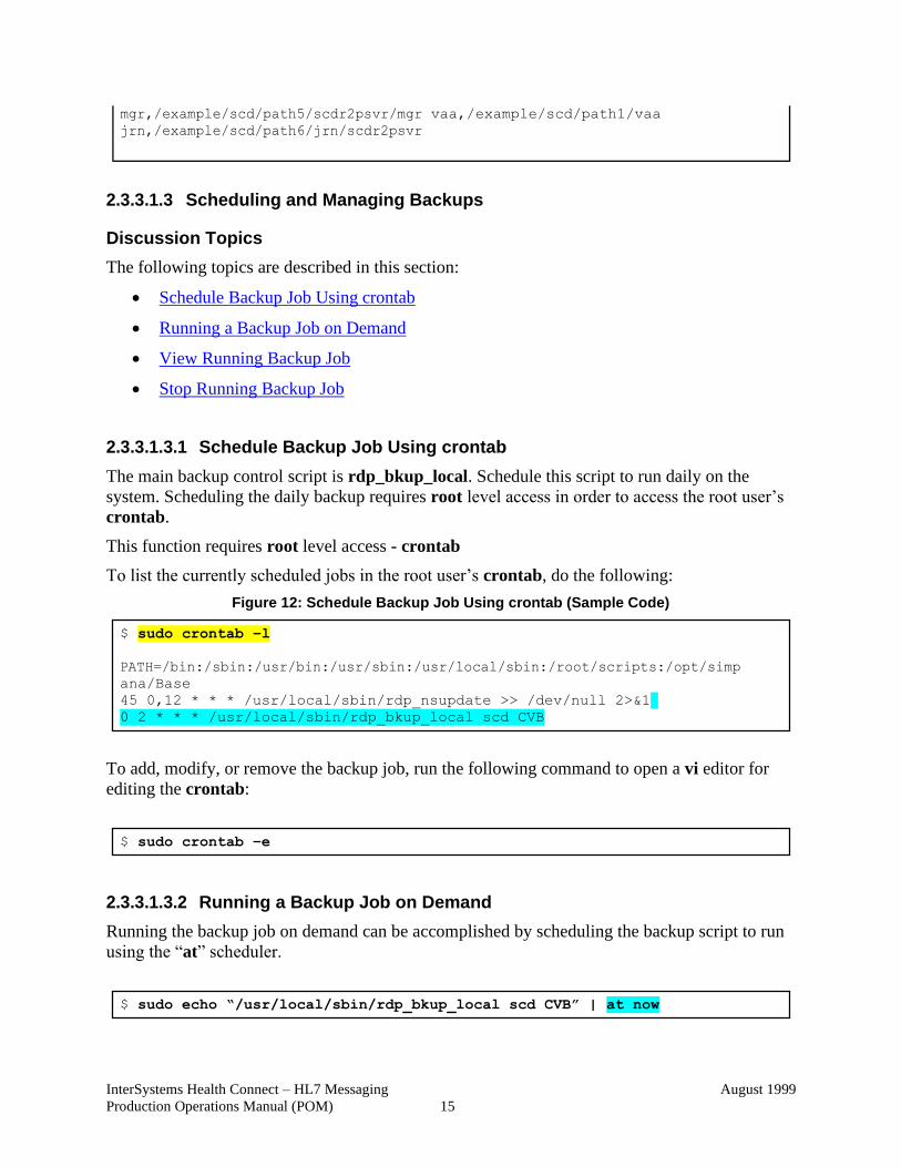
2.3.3.1.3.1 Schedule Backup Job Using crontab
The main backup control script is rdp_bkup_local. Schedule this script to run daily on the
system. Scheduling the daily backup requires root level access in order to access the root user’s
crontab.
This function requires root level access - crontab
To list the currently scheduled jobs in the root user’s crontab, do the following:
Figure 12: Schedule Backup Job Using crontab (Sample Code)
To add, modify, or remove the backup job, run the following command to open a vi editor for
editing the crontab:
2.3.3.1.3.2 Running a Backup Job on Demand
Running the backup job on demand can be accomplished by scheduling the backup script to run
using the “at” scheduler.
vaa,/example/scd/path1/vaa
$ sudo crontab –l
PATH=/bin:/sbin:/usr/bin:/usr/sbin:/usr/local/sbin:/root/scripts:/opt/simp
ana/Base
45 0,12 * * * /usr/local/sbin/rdp_nsupdate >> /dev/null 2>&1
0 2 * * * /usr/local/sbin/rdp_bkup_local scd CVB
$ sudo crontab –e
$ sudo echo “/usr/local/sbin/rdp_bkup_local scd CVB” | at now
InterSystems Health Connect – HL7 Messaging
Production Operations Manual (POM)
August 1999
16
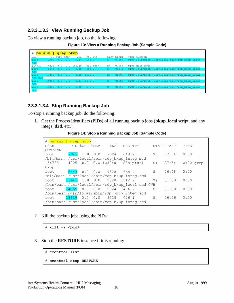
2.3.3.1.3.3 View Running Backup Job
To view a running backup job, do the following:
Figure 13: View a Running Backup Job (Sample Code)
# ps aux | grep bkup USER PID %CPU %MEM VSZ RSS TTY STAT START TIME COMMAND
root 2967 0.0 0.0 9324 648 ? S 07:54 0:00 /bin/bash /usr/local/sbin/rdp_bkup_integ
scd
154738 4225 0.0 0.0 103240 888 pts/1 S+ 07:54 0:00 grep bkup
root 6643 0.0 0.0 9328 668 ? S 06:48 0:00 /bin/bash /usr/local/sbin/rdp_bkup_integ
scd
root 10469 0.0 0.0 9328 1512 ? Ss 01:00 0:00 /bin/bash /usr/local/sbin/rdp_bkup_local
scd CVB
root 14065 0.0 0.0 9324 1476 ? S 01:00 0:00 /bin/bash /usr/local/sbin/rdp_bkup_integ
scd
root 18819 0.0 0.0 9328 676 ? S 06:56 0:00 /bin/bash /usr/local/sbin/rdp_bkup_integ
scd
2.3.3.1.3.4 Stop Running Backup Job
To stop a running backup job, do the following:
1. Get the Process Identifiers (PIDs) of all running backup jobs (bkup_local script, and any
integs, d2d, etc.):
Figure 14: Stop a Running Backup Job (Sample Code)
USER
COMMAND
PID %CPU %MEM VSZ RSS TTY STAT START TIME
root 2967 0.0 0.0 9324 648 ? S 07:54 0:00
/bin/bash
154738
bkup
root
/bin/bash
/usr/local/sbin/rdp_bkup_integ scd
4225 0.0 0.0 103240 888 pts/1
6643 0.0 0.0 9328 668 ?
/usr/local/sbin/rdp_bkup_integ scd
S+
S
07:54
06:48
0:00
0:00
grep
root 10469 0.0 0.0 9328 1512 ? Ss 01:00 0:00
/bin/bash /usr/local/sbin/rdp_bkup_local scd CVB
root 14065 0.0 0.0 9324 1476 ?
/bin/bash /usr/local/sbin/rdp_bkup_integ
root 18819 0.0 0.0 9328 676 ?
/bin/bash /usr/local/sbin/rdp_bkup_integ
scd
scd
S
S
01:00
06:56
0:00
0:00
2. Kill the backup jobs using the PIDs:
3. Stop the RESTORE instance if it is running:
# ps aux | grep bkup
# kill -9 <pid>
# ccontrol list
# ccontrol stop RESTORE
InterSystems Health Connect – HL7 Messaging
Production Operations Manual (POM)
August 1999
17
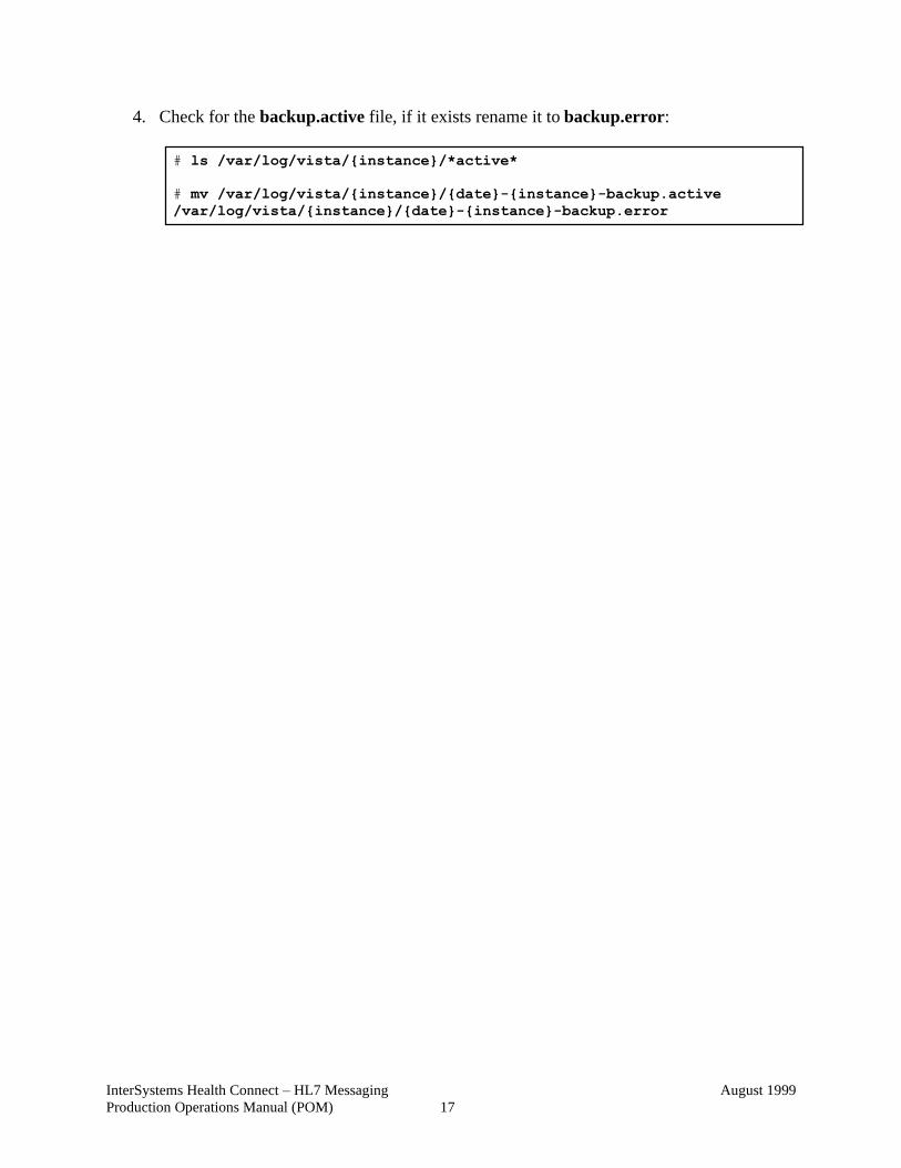
4. Check for the backup.active file, if it exists rename it to backup.error:
# ls /var/log/vista/{instance}/*active*
# mv /var/log/vista/{instance}/{date}-{instance}-backup.active
/var/log/vista/{instance}/{date}-{instance}-backup.error
InterSystems Health Connect – HL7 Messaging
Production Operations Manual (POM)
August 1999
18
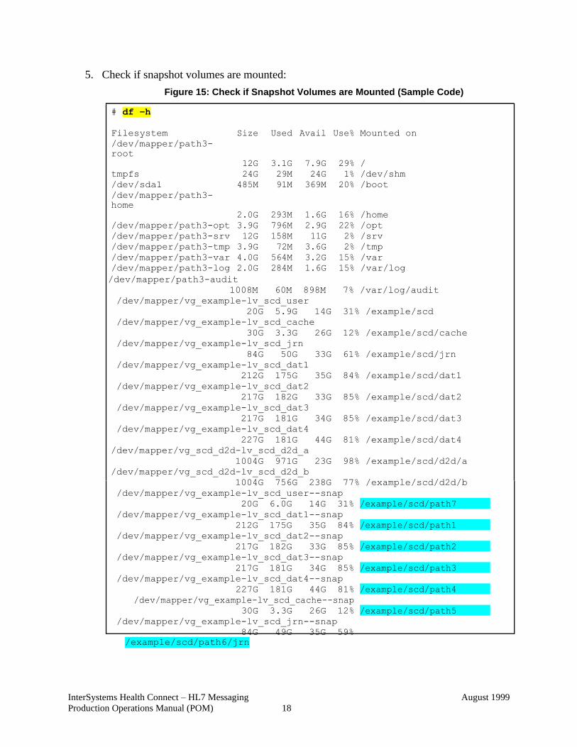
5. Check if snapshot volumes are mounted:
Figure 15: Check if Snapshot Volumes are Mounted (Sample Code)
# df –h
Filesystem
Size
Used
Avail
Use%
Mounted on
/dev/mapper/path3-
root
12G 3.1G 7.9G 29% /
tmpfs 24G 29M 24G 1% /dev/shm
/dev/sda1 485M 91M 369M 20% /boot
/dev/mapper/path3-
home
2.0G 293M 1.6G 16% /home
/dev/mapper/path3-opt 3.9G 796M 2.9G 22% /opt
/dev/mapper/path3-srv 12G 158M 11G 2% /srv
/dev/mapper/path3-tmp 3.9G 72M 3.6G 2% /tmp
/dev/mapper/path3-var 4.0G 564M 3.2G 15% /var
/dev/mapper/path3-log 2.0G 284M 1.6G 15% /var/log
/dev/mapper/path3-audit
1008M 60M 898M 7% /var/log/audit
/dev/mapper/vg_example-lv_scd_user
20G 5.9G 14G 31% /example/scd
/dev/mapper/vg_example-lv_scd_cache
30G 3.3G 26G 12% /example/scd/cache
/dev/mapper/vg_example-lv_scd_jrn
84G 50G 33G 61% /example/scd/jrn
/dev/mapper/vg_example-lv_scd_dat1
212G 175G 35G 84% /example/scd/dat1
/dev/mapper/vg_example-lv_scd_dat2
217G 182G 33G 85% /example/scd/dat2
/dev/mapper/vg_example-lv_scd_dat3
217G 181G 34G 85% /example/scd/dat3
/dev/mapper/vg_example-lv_scd_dat4
227G 181G 44G 81% /example/scd/dat4
/dev/mapper/vg_scd_d2d-lv_scd_d2d_a
1004G 971G 23G 98% /example/scd/d2d/a
/dev/mapper/vg_scd_d2d-lv_scd_d2d_b
1004G 756G 238G 77% /example/scd/d2d/b
/dev/mapper/vg_example-lv_scd_user--snap
20G 6.0G 14G 31%
/dev/mapper/vg_example-lv_scd_dat1--snap
212G 175G 35G 84%
/dev/mapper/vg_example-lv_scd_dat2--snap
217G 182G 33G 85%
/dev/mapper/vg_example-lv_scd_dat3--snap
217G 181G 34G 85%
/dev/mapper/vg_example-lv_scd_dat4--snap
227G 181G 44G 81%
/dev/mapper/vg_example-lv_scd_cache--snap
30G 3.3G 26G 12%
/dev/mapper/vg_example-lv_scd_jrn--snap
84G 49G 35G 59%
/example/scd/path6/jrn
/example/scd/path5
/example/scd/path4
/example/scd/path3
/example/scd/path2
/example/scd/path1
/example/scd/path7
InterSystems Health Connect – HL7 Messaging
Production Operations Manual (POM)
August 1999
19
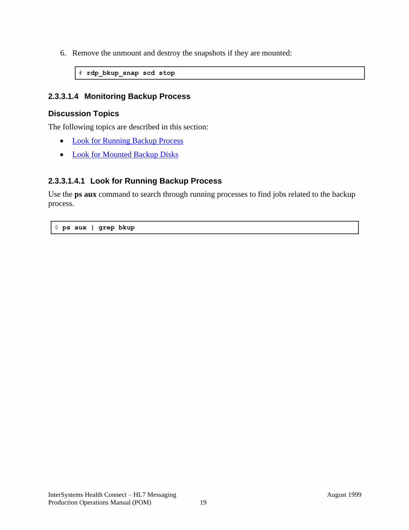
6. Remove the unmount and destroy the snapshots if they are mounted:
2.3.3.1.4 Monitoring Backup Process
Discussion Topics
The following topics are described in this section:
• Look for Running Backup Process
• Look for Mounted Backup Disks
2.3.3.1.4.1 Look for Running Backup Process
Use the ps aux command to search through running processes to find jobs related to the backup
process.
# rdp_bkup_snap scd stop
$ ps aux | grep bkup
InterSystems Health Connect – HL7 Messaging
Production Operations Manual (POM)
August 1999
20
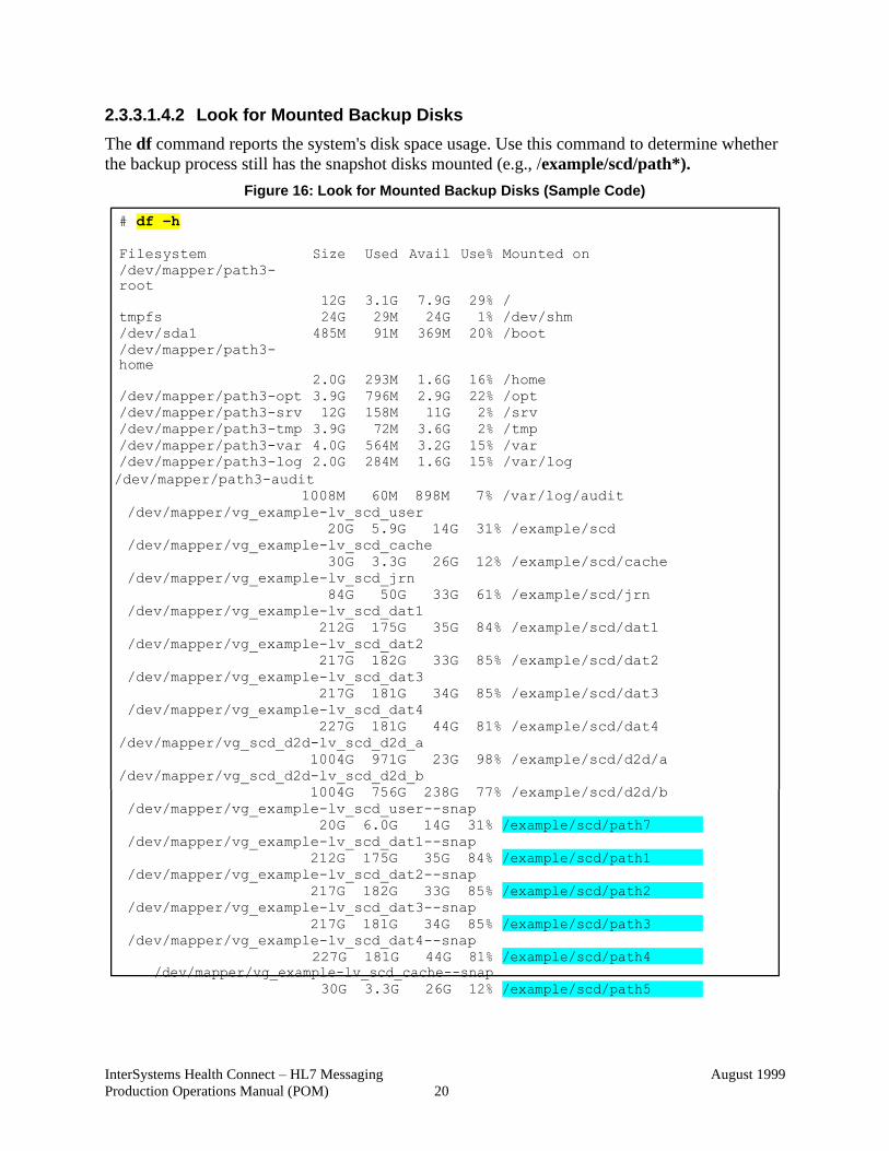
2.3.3.1.4.2 Look for Mounted Backup Disks
The df command reports the system's disk space usage. Use this command to determine whether
the backup process still has the snapshot disks mounted (e.g., /example/scd/path*).
Figure 16: Look for Mounted Backup Disks (Sample Code)
# df –h
Filesystem
Size
Used
Avail
Use%
Mounted on
/dev/mapper/path3-
root
12G 3.1G 7.9G 29% /
tmpfs 24G 29M 24G 1% /dev/shm
/dev/sda1 485M 91M 369M 20% /boot
/dev/mapper/path3-
home
2.0G 293M 1.6G 16% /home
/dev/mapper/path3-opt 3.9G 796M 2.9G 22% /opt
/dev/mapper/path3-srv 12G 158M 11G 2% /srv
/dev/mapper/path3-tmp 3.9G 72M 3.6G 2% /tmp
/dev/mapper/path3-var 4.0G 564M 3.2G 15% /var
/dev/mapper/path3-log 2.0G 284M 1.6G 15% /var/log
/dev/mapper/path3-audit
1008M 60M 898M 7% /var/log/audit
/dev/mapper/vg_example-lv_scd_user
20G 5.9G 14G 31% /example/scd
/dev/mapper/vg_example-lv_scd_cache
30G 3.3G 26G 12% /example/scd/cache
/dev/mapper/vg_example-lv_scd_jrn
84G 50G 33G 61% /example/scd/jrn
/dev/mapper/vg_example-lv_scd_dat1
212G 175G 35G 84% /example/scd/dat1
/dev/mapper/vg_example-lv_scd_dat2
217G 182G 33G 85% /example/scd/dat2
/dev/mapper/vg_example-lv_scd_dat3
217G 181G 34G 85% /example/scd/dat3
/dev/mapper/vg_example-lv_scd_dat4
227G 181G 44G 81% /example/scd/dat4
/dev/mapper/vg_scd_d2d-lv_scd_d2d_a
1004G 971G 23G 98% /example/scd/d2d/a
/dev/mapper/vg_scd_d2d-lv_scd_d2d_b
1004G 756G 238G 77% /example/scd/d2d/b
/dev/mapper/vg_example-lv_scd_user--snap
20G 6.0G 14G 31%
/dev/mapper/vg_example-lv_scd_dat1--snap
212G 175G 35G 84%
/dev/mapper/vg_example-lv_scd_dat2--snap
217G 182G 33G 85%
/dev/mapper/vg_example-lv_scd_dat3--snap
217G 181G 34G 85%
/dev/mapper/vg_example-lv_scd_dat4--snap
227G 181G 44G 81%
/dev/mapper/vg_example-lv_scd_cache--snap
30G 3.3G 26G 12% /example/scd/path5
/example/scd/path4
/example/scd/path3
/example/scd/path2
/example/scd/path1
/example/scd/path7
InterSystems Health Connect – HL7 Messaging
Production Operations Manual (POM)
August 1999
21
2.3.3.1.5 Monitoring Backup Log Files
Discussion Topics
The following topics are described in this section:
• /var/log/vista/<instance> File
• /var/log/messages File
2.3.3.1.5.1 /var/log/vista/<instance> File
Most of the backup log files can be found in the following directory:
/var/log/vista/<instance>
Some of the included log files are:
• Summary Backup Log file:
<date>-<instance>-backup.log
• Summary Integrity Log file:
<date>-<job>-integrits.log
• Individual Integrity Log file:
<database>-<date>-<job>-integ.log
Also, the backup.active file can be found in the following directory:
/var/log/vista/<instance>
REF: For a list of VistA instances by region, see the
HC_HL_App_Server_Standards_All_Regions_MASTER.xlsx Microsoft® Excel
document located at: http://go.va.gov/sxcu.
2.3.3.1.5.2 /var/log/messages File
The /var/log/messages file can also be monitored for backup activity, including the mounting
and unmounting of snapshots volumes.
2.3.3.2 Restore Procedures
This section describes how to restore the system from a backup.
The HL7 Health Connect restore procedures are TBD.
2.3.3.3 Back-Up Testing
Periodic tests verify that backups are accurate and can be used to restore the system. This section
describes the procedure to test each of the back-up types described in the back-up section. It
describes the regular testing schedule. It also describes the basic operational tests to be
performed as well as specific data quality tests.
InterSystems Health Connect – HL7 Messaging
Production Operations Manual (POM)
August 1999
22
The VA and HL7 Health Connect will perform backup services and will also ensure those
backups are tested to verify the backup was successfully completed.
The HL7 Health Connect backup testing process is TBD.
2.3.3.4 Storage and Rotation
This section describes how, when (schedule), and where HL7 Health Connect backup media is
stored and transported to and from an off-site location. It includes names and contact information
for all principals at the remote facility.
The HL7 Health Connect storage and rotation process is TBD.
2.4 Security / Identity Management
This section describes the security architecture of the system, including the authentication and
authorization mechanisms.
HL7 Health Connect uses Caché encryption at the database level.
REF: For more information and to get an architectural overview (e.g., Datacenter
regional diagram), see the Regional HealthConnect Installation - All RDCs document
(i.e., Regional_HealthConnect_Installation_All_RDCs.docx) located at:
http://go.va.gov/sxcu
2.4.1 Identity Management
This section defines the procedures for adding new users, giving and modifying rights, and
deactivating users. It includes the administrative process for granting access rights and any
authorization levels, if more than one exists. Describe what level of administrator has the
authority for user management:
• Authentication—Process of proving your identity (i.e., who are you?). Authentication
can take many forms, such as user identification (ID) and password, token, digital
certificate, and biometrics.
• Authorization—Takes the authenticated identity and verifies if you have the necessary
privileges or assigned role to perform the action you are requesting on the resource you
are seeking to act upon.
This is perhaps the cornerstone of any security architecture, since security is largely focused on
providing the proper level of access to resources.
The HL7 Health Connect identity management process is TBD.
2.4.2 Access Control
This section describes the systems access control functionality. It includes security procedures
and configurations not covered in the previous section. It includes any password aging and/or
strictness controls, user/security group management, key management, and temporary rights.
InterSystems Health Connect – HL7 Messaging
Production Operations Manual (POM)
August 1999
23
Safeguarding data and access to that data is an important function of the VA. An enterprise-wide
security approach includes the interrelationships between security policy, process, and
technology (and implications by their organizational analogs). VA security addresses the
following services.
• Authentication
• Authorization
• Confidentiality
• Data Integrity
The HL7 Health Connect access control process is TBD.
2.4.3 Audit Control
To access the HL7 Health Connect “Auditing” screen, do the following:
SMP → System Administration → Security → Auditing
Redacted Figure 17: Audit Control
2.5 User Notifications
This section defines the process and procedures used to notify the user community of any
scheduled or unscheduled changes in the system state. It includes planned outages, system
upgrades, and any other maintenance work, plus any unexpected system outages.
The HL7 Health Connect user notifications process is TBD.
2.5.1 User Notification Points of Contact
This section identifies the key individuals or organizations that must be informed of a system
outage, system or software upgrades to include schedule or unscheduled maintenance, or system
InterSystems Health Connect – HL7 Messaging
Production Operations Manual (POM)
August 1999
24
changes. The table lists the Name/Organization/Phone #/E-Mail Address/Method of notification
(phone or E-Mail)/Notification Priority/Time of Notification).
The HL7 Health Connect user notification points of contact are TBD.
2.6 System Monitoring, Reporting, & Tools
This section describes the high-level approach to monitoring the HL7 Health Connect system. It
covers items needed to insure high availability. The HL7 Health Connect monitoring tools
include:
• Ensemble System Monitor
• InterSystems Diagnostic Tools:
o ^Buttons
o ^pButtons
o cstat
o mgstat
CAUTION: The InterSystems Diagnostic Tools should only be used with the recommendation and assistance of the InterSystems Support team.
2.6.1 Support
2.6.1.1 Tier 2
Use the following Tier 2 email distribution group to add appropriate members/roles to be notified
when needed:
OIT EPMO TRS EPS HSH HealthConnect Administration REDACTED
2.6.1.2 VA Enterprise Service Desk (ESD)
For Information Technology (IT) support 24 hours a day, 365 days a year call the VA Enterprise
Service Desk:
• Phone: REDACTED
• Information Technology Service Management (ITSM) Tool—ServiceNow site:
REDACTED
• Enter an Incident or Request ticket (YourIT) in ITSM ServiceNow system via the
shortcut on your workstation.
InterSystems Health Connect – HL7 Messaging
Production Operations Manual (POM)
August 1999
25
2.6.1.3 InterSystems Support
If you are unable to diagnose any of the HL7 Health Connect system issues, contact the
InterSystems Support team at:
• Email: [email protected]
• Worldwide Response Center (WRC) Direct Phone: 617-621-0700.
2.6.2 Monitor Commands
All of the commands in this section are run from the Linux prompt.
REF: For information on Linux system monitoring, see the OIT Service Line
documentation.
2.6.2.1 ps Command
The ps ax command displays a list of current system processes, including processes owned by
other users. To display the owner alongside each process, use the ps aux command. This list is a
static list; in other words, it is a snapshot of what was running when you invoked the command.
If you want a constantly updated list of running processes, use top as described in the “top
Command” section.
The ps output can be long. To prevent it from scrolling off the screen, you can pipe it through
less:
You can use the ps command in combination with the grep command to see if a process is
running. For example, to determine if Emacs is running, use the following command:
ps aux | less
ps ax | grep emacs
InterSystems Health Connect – HL7 Messaging
Production Operations Manual (POM)
August 1999
26
0.17, 0.65, 1.00
0 stopped,
2.0% sy, 0.0% ni, 56.6% id, 0.0% wa, 0.0%
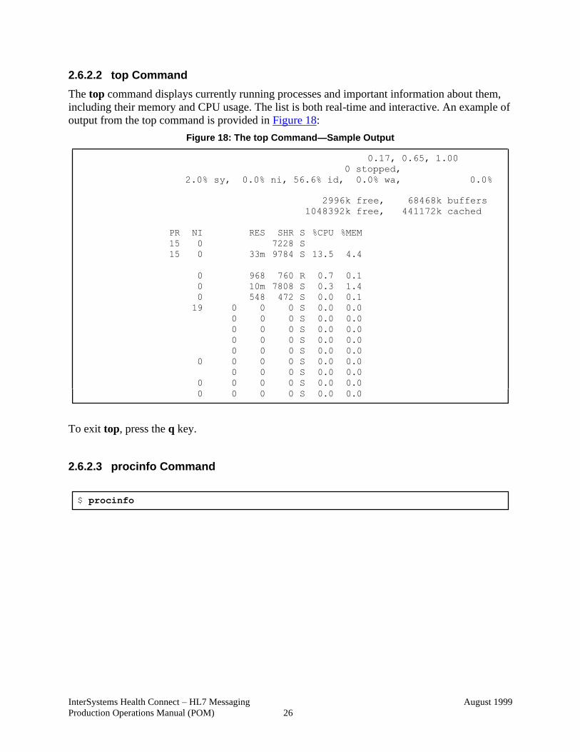
2.6.2.2 top Command
The top command displays currently running processes and important information about them,
including their memory and CPU usage. The list is both real-time and interactive. An example of
output from the top command is provided in Figure 18:
Figure 18: The top Command—Sample Output
2996k free, 68468k buffers
1048392k free, 441172k cached
PR NI RES SHR S %CPU %MEM
15 0 7228 S
15 0 33m 9784 S 13.5 4.4
0 968 760 R 0.7 0.1
0 10m 7808 S 0.3 1.4
0 548 472 S 0.0 0.1
19 0 0 0 S 0.0 0.0
0 0 0 S 0.0 0.0
0 0 0 S 0.0 0.0
0 0 0 S 0.0 0.0
0 0 0 S 0.0 0.0
0 0 0 0 S 0.0 0.0
0 0 0 S 0.0 0.0
0 0 0 0 S 0.0 0.0
0 0 0 0 S 0.0 0.0
To exit top, press the q key.
2.6.2.3 procinfo Command
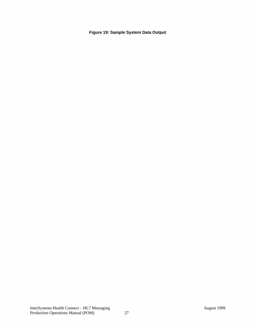
$ procinfo
InterSystems Health Connect – HL7 Messaging
Production Operations Manual (POM)
August 1999
27
Figure 19: Sample System Data Output
InterSystems Health Connect – HL7 Messaging
Production Operations Manual (POM)
August 1999
28
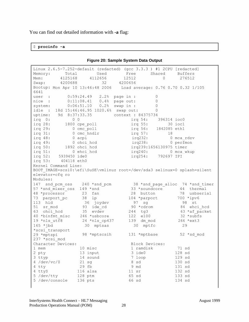
You can find out detailed information with -a flag:
Figure 20: Sample System Data Output
Linux 2.6.5-7.252-default (redacted) (gcc 3.3.3 ) #1 2CPU [redacted]
Memory: Total Used Free Shared Buffers
Mem: 4125168 4112656 12512 0 276512
Swap: 4200688 32 4200656
Bootup:
6641
user :
Mon Apr 10 13:46:48 2006
0:59:24.49 2.2%
Load average: 0.76 0.70 0.32 1/105
page in : 0
nice : 0:11:08.41 0.4% page out: 0
system: 0:06:51.10 0.2% swap in : 0
idle : 18d 15:46:46.95 1020.6% swap out: 0
uptime: 9d 8:37:33.35 context : 84375734
irq 0: 0 0 irq 54: 396314 ioc0
irq 28: 1800 cpe_poll irq 55: 30 ioc1
irq 29: 0 cmc_poll irq 56: 1842085 eth1
irq 31: 0 cmc_hndlr irq 57: 18
irq 48: 0 acpi irq232: 0 mca_rdzv
irq 49: 0 ohci_hcd irq238: 0 perfmon
irq 50: 1892 ohci_hcd irq239:1656130975 timer
irq 51: 0 ehci_hcd irq240: 0 mca_wkup
irq 52: 5939450 ide0 irq254: 792697 IPI
irq 53: 404118 eth0
Kernel Command Line:
BOOT_IMAGE=scsi0:\efi\SuSE\vmlinuz root=/dev/sda3 selinux=0 splash=silent
elevator=cfq ro
Modules:
147 snd_pcm_oss 240 *snd_pcm 38 *snd_page_alloc 74 *snd_timer
57 *snd_mixer_oss 149 *snd 33 *soundcore 44 thermal
48 *processor 23 fan 28 button 78 usbserial
73 parport_pc 38 lp 104 *parport 700 *ipv6
113 hid 36 joydev 97 sg 98 st
51 sr_mod 93 ide_cd 90 *cdrom 84 ehci_hcd
63 ohci_hcd 35 evdev 244 tg3 63 *af_packet
40 *binfmt_misc 246 *usbcore 122 e100 32 *subfs
19 *nls_utf8 24 *nls_cp437 139 dm_mod 266 *ext3
165 *jbd
*scsi_transport
29 *mptspi
237 *scsi_mod
30 mptsas
98 *mptscsih
30 mptfc 29
131 *mptbase 52 *sd_mod
Character Devices:
1 mem
10
misc
Block Devices:
1 ramdisk
71
sd
2 pty 13 input 3 ide0 128 sd
3 ttyp 14 sound 7 loop 129 sd
4 /dev/vc/0 21 sg 8 sd 130 sd
4 tty 29 fb 9 md 131 sd
4 ttyS 116 alsa 11 sr 132 sd
5 /dev/tty 128 ptm 65 sd 133 sd
5 /dev/console 136 pts 66 sd 134 sd
$ procinfo -a
InterSystems Health Connect – HL7 Messaging
Production Operations Manual (POM)
August 1999
29
5 /dev/ptmx 6 lp mapper
180 usb
188 ttyUSB
67 sd 68 sd
135 sd
253 device-
7 vcs 254 snsc 69 sd 254 mdp
9 st 70 sd
File Systems:
ext3 [sysfs] [rootfs] [bdev]
[proc] [cpuset] [sockfs] [pfmfs]
[futexfs] [tmpfs] [pipefs] [eventpollfs]
[devpts] ext2 [ramfs] [hugetlbfs]
minix msdos vfat iso9660
[nfs] [nfs4] [mqueue] [rpc_pipefs]
[subfs] [usbfs] [usbdevfs] [binfmt_misc]
2.6.3 Other Options
• -f—Run procinfo continuously full-screen (update status on screen, the default is 5
seconds, use -n SEC to setup pause).
• -Ffile—Redirect output to file (usually a tty). For example:
procinfo -biDn1 -F/dev/tty5
• Pstree—Process monitoring can also be achieved using the pstree command. It displays
a snapshot of running process. It always uses a tree-like display like ps f:
o By default, it shows only the name of each command.
o Specify a pid as an argument to show a specific process and its descendants.
o Specify a user name as an argument to show process trees owned by that user.
• Pstree options:
o -a—Display commands’ arguments.
o -c—Do not compact identical subtrees.
o -G—Attempt to use terminal-specific line-drawing characters.
o -hHighlight—Ancestors of the current process.
o -n—Sort processes numerically by pid, rather than alphabetically by name.
o -p—Include pids in the output.
2.6.4 Dataflow Diagram
For a Dataflow diagram, see the InterSystems Health Connect documentation.
2.6.5 Availability Monitoring
This section describes the procedure to determine the overall operational state and the state of the
individual components for the HL7 Health Connect system.
The following Caché command from a Linux prompt displays the currently installed instances on
the server. It also indicates the current status and state of the installed instances:
$ ccontrol list
InterSystems Health Connect – HL7 Messaging
Production Operations Manual (POM)
August 1999
30
REF: For more information on the ccontrol command, see Step 1 in Section 2.3.1,
“System Start-Up.”
2.6.6 High Availability Mirror Monitoring
Mirror monitoring is a system in which there are backup systems containing all tracked
databases. This tracked database is used for failover situations in case the primary system fails.
One situation that allows for a failover is disaster recovery in which the failover node takes over
when the primary system is down; this occurs with no downtime.
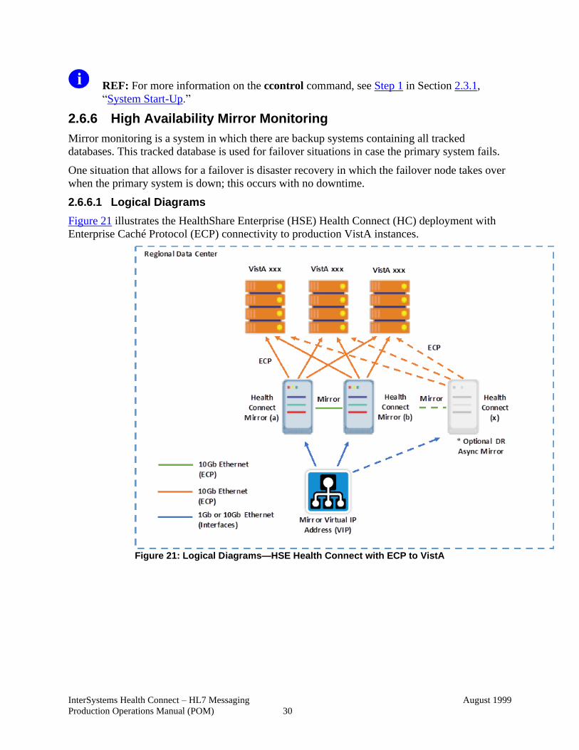
2.6.6.1 Logical Diagrams
Figure 21 illustrates the HealthShare Enterprise (HSE) Health Connect (HC) deployment with
Enterprise Caché Protocol (ECP) connectivity to production VistA instances.
Figure 21: Logical Diagrams—HSE Health Connect with ECP to VistA
InterSystems Health Connect – HL7 Messaging
Production Operations Manual (POM)
August 1999
31
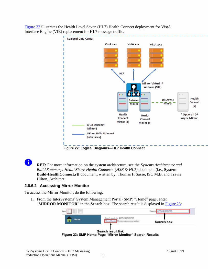
Figure 22 illustrates the Health Level Seven (HL7) Health Connect deployment for VistA
Interface Engine (VIE) replacement for HL7 message traffic.
Figure 22: Logical Diagrams—HL7 Health Connect
REF: For more information on the system architecture, see the Systems Architecture and
Build Summary: HealthShare Health Connects-(HSE & HL7) document (i.e., System-
Build-HealthConnect.rtf document; written by: Thomas H Sasse, ISC M.B. and Travis
Hilton, Architect.
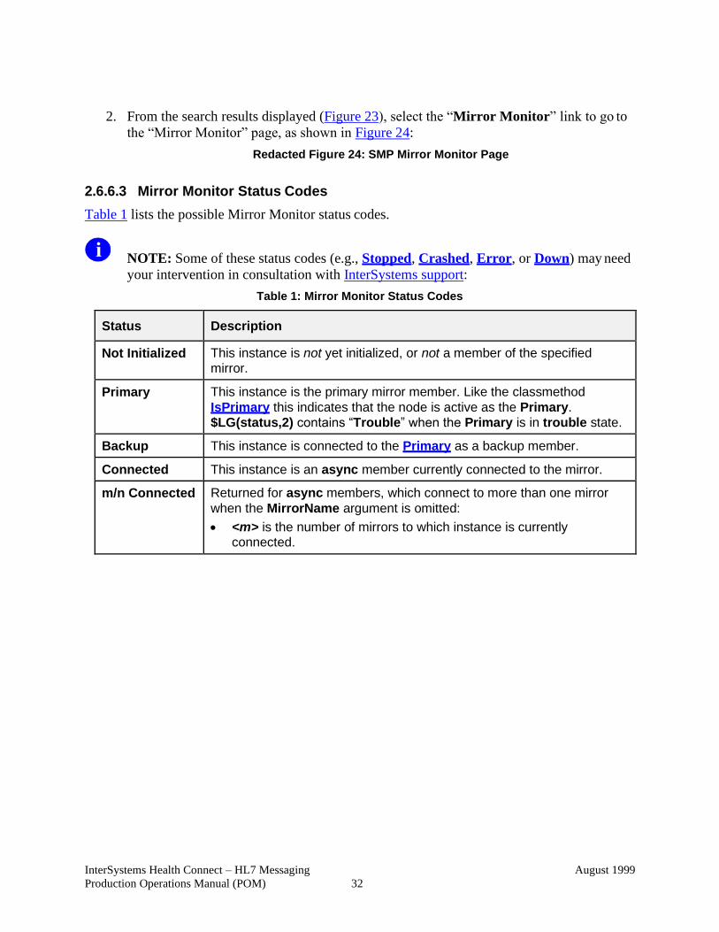
2.6.6.2 Accessing Mirror Monitor
To access the Mirror Monitor, do the following:
1. From the InterSystems’ System Management Portal (SMP) “Home” page, enter
“MIRROR MONITOR” in the Search box. The search result is displayed in Figure 23:
Figure 23: SMP Home Page “Mirror Monitor” Search Results
InterSystems Health Connect – HL7 Messaging
Production Operations Manual (POM)
August 1999
32
2. From the search results displayed (Figure 23), select the “Mirror Monitor” link to go to
the “Mirror Monitor” page, as shown in Figure 24:
Redacted Figure 24: SMP Mirror Monitor Page
2.6.6.3 Mirror Monitor Status Codes
Table 1 lists the possible Mirror Monitor status codes.
NOTE: Some of these status codes (e.g., Stopped, Crashed, Error, or Down) may need
your intervention in consultation with InterSystems support:
Table 1: Mirror Monitor Status Codes
Status Description
Not Initialized This instance is not yet initialized, or not a member of the specified
mirror.
Primary This instance is the primary mirror member. Like the classmethod
IsPrimary this indicates that the node is active as the Primary.
$LG(status,2) contains “Trouble” when the Primary is in trouble state.
Backup This instance is connected to the Primary as a backup member.
Connected This instance is an async member currently connected to the mirror.
m/n Connected Returned for async members, which connect to more than one mirror
when the MirrorName argument is omitted:
• <m> is the number of mirrors to which instance is currently connected.
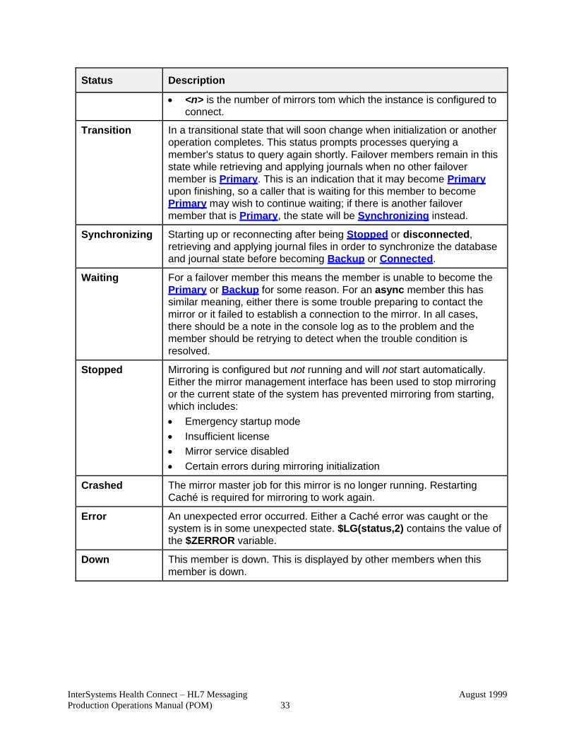
InterSystems Health Connect – HL7 Messaging
Production Operations Manual (POM)
August 1999
33
Status Description
• <n> is the number of mirrors tom which the instance is configured to connect.
Transition In a transitional state that will soon change when initialization or another
operation completes. This status prompts processes querying a
member's status to query again shortly. Failover members remain in this
state while retrieving and applying journals when no other failover
member is Primary. This is an indication that it may become Primary
upon finishing, so a caller that is waiting for this member to become
Primary may wish to continue waiting; if there is another failover
member that is Primary, the state will be Synchronizing instead.
Synchronizing Starting up or reconnecting after being Stopped or disconnected,
retrieving and applying journal files in order to synchronize the database
and journal state before becoming Backup or Connected.
Waiting For a failover member this means the member is unable to become the
Primary or Backup for some reason. For an async member this has
similar meaning, either there is some trouble preparing to contact the
mirror or it failed to establish a connection to the mirror. In all cases,
there should be a note in the console log as to the problem and the
member should be retrying to detect when the trouble condition is
resolved.
Stopped Mirroring is configured but not running and will not start automatically.
Either the mirror management interface has been used to stop mirroring
or the current state of the system has prevented mirroring from starting,
which includes:
• Emergency startup mode
• Insufficient license
• Mirror service disabled
• Certain errors during mirroring initialization
Crashed The mirror master job for this mirror is no longer running. Restarting
Caché is required for mirroring to work again.
Error An unexpected error occurred. Either a Caché error was caught or the
system is in some unexpected state. $LG(status,2) contains the value of
the $ZERROR variable.
Down This member is down. This is displayed by other members when this
member is down.
InterSystems Health Connect – HL7 Messaging
Production Operations Manual (POM)
August 1999
34
2.6.6.4 Monitoring System Alerts
This section describes the possible console log and email alerts indicating system trouble at
Level 2 or higher. The three severity levels of console log entries generating notifications are:
• 1—Warning, Severe, and Fatal
• 2—Severe and Fatal
• 3—Fatal only
Anyone belonging to the Tier 2 email group may receive email notifications. Figure 25 is a
sample email message indicating system alerts:
Redacted Figure 25: Sample Production Message
NOTE: For email notification setup and configuration, see “Appendix B—Configuring
Alert Email Notification.”
In addition to email notifications, these errors are reported to the cconsole.log. The cconsole.log
file location is:
<instance path>/mgr/cconsole.log
To find this log file, enter the following command at a Linux prompt:
control list
When this log reaches capacity (currently set at 5 megabytes), it appends a date and time to the
file name and then starts a new cconsole.log file:
<instance path>/mgr/cconsole.log.<date/Time>
In some cases, you may need to review several log files over a period of time to get a complete
picture of any recent occurrences.
InterSystems Health Connect – HL7 Messaging
Production Operations Manual (POM)
August 1999
35
2.6.6.4.1 Console Log Page
To access the SMP “Console Log” page, do the following:
SMP→ System Operation → System Logs → Console Log
Redacted Figure 26: Sample SMP Console Log Page with Alerts (1 of 2)
Redacted Figure 27: Sample SMP Console Log Page with Alerts (2 of 2)
System issues are displayed in a list from oldest at the top to most recent occurrence at the
bottom.
The second column (see green boxes in Figure 26 and Figure 27) indicates the alert level number
(e.g., 0 or 2). Level 2 alerts need to be reviewed and possible action required.
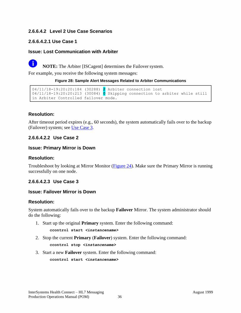
InterSystems Health Connect – HL7 Messaging
Production Operations Manual (POM)
August 1999
36
2.6.6.4.2 Level 2 Use Case Scenarios
2.6.6.4.2.1 Use Case 1
Issue: Lost Communication with Arbiter
NOTE: The Arbiter [ISCagent] determines the Failover system.
For example, you receive the following system messages:
Figure 28: Sample Alert Messages Related to Arbiter Communications
Resolution:
After timeout period expires (e.g., 60 seconds), the system automatically fails over to the backup
(Failover) system; see Use Case 3.
2.6.6.4.2.2 Use Case 2
Issue: Primary Mirror is Down
Resolution:
Troubleshoot by looking at Mirror Monitor (Figure 24). Make sure the Primary Mirror is running
successfully on one node.
2.6.6.4.2.3 Use Case 3
Issue: Failover Mirror is Down
Resolution:
System automatically fails over to the backup Failover Mirror. The system administrator should
do the following:
1. Start up the original Primary system. Enter the following command:
ccontrol start <instancename>
2. Stop the current Primary (Failover) system. Enter the following command:
ccontrol stop <instancename>
3. Start a new Failover system. Enter the following command:
ccontrol start <instancename>
04/11/18-19:20:20:184 (30288) 2 Arbiter connection lost
04/11/18-19:20:20:213 (30084) 0 Skipping connection to arbiter while still
in Arbiter Controlled failover mode.
InterSystems Health Connect – HL7 Messaging
Production Operations Manual (POM)
August 1999
37
2.6.6.4.2.4 Use Case 4
Issue: ISCagent is Down
Resolution:
Call InterSystems support.
2.6.7 System/Performance/Capacity Monitoring
This section details the following InterSystems monitoring and diagnostic tools available in HL7
Health Connect:
• Ensemble System Monitor
• InterSystems Diagnostic Tools:
o ^Buttons
o ^pButtons
o cstat
o mgstat
CAUTION: The InterSystems Diagnostic Tools should only be used with the recommendation and assistance of the InterSystems Support team.
2.6.7.1 Ensemble System Monitor
The HL7 Health Connect “Ensemble System Monitor” page (Figure 29, Figure 30, and Figure
31) provides a high-level view of the state of the system, across all namespaces. It displays
Ensemble information combined with a subset of the information shown on the “System
Dashboard” page (Figure 32), which is provided for the users of HL7 Health Connect.
REF: For more information on the Ensemble System Monitor, see InterSystems’
documentation at:
http://docs.intersystems.com/latest/csp/docbook/DocBook.UI.Page.cls?KEY=EMONITO
R_all
To access the HL7 Health Connect Ensemble System Monitor, do the following:
System Management Portal (SMP) → Ensemble → Monitor → System Monitor

InterSystems Health Connect – HL7 Messaging
Production Operations Manual (POM)
August 1999
38
Redacted Figure 29: Accessing the Ensemble System Monitor from SMP
Redacted Figure 30: Ensemble Production Monitor (1 of 2)

InterSystems Health Connect – HL7 Messaging
Production Operations Manual (POM)
August 1999
39
Redacted Figure 31: Ensemble Production Monitor (2 of 2)
Redacted Figure 32: System Dashboard
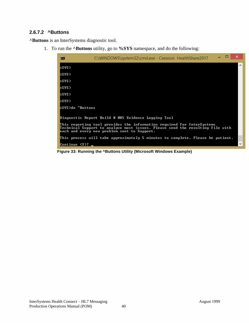
InterSystems Health Connect – HL7 Messaging
Production Operations Manual (POM)
August 1999
40
2.6.7.2 ^Buttons
^Buttons is an InterSystems diagnostic tool.
1. To run the ^Buttons utility, go to %SYS namespace, and do the following:
Figure 33: Running the ^Buttons Utility (Microsoft Windows Example)
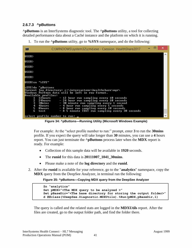
InterSystems Health Connect – HL7 Messaging
Production Operations Manual (POM)
August 1999
41
2.6.7.3 ^pButtons
^pButtons is an InterSystems diagnostic tool. The ^pButtons utility, a tool for collecting
detailed performance data about a Caché instance and the platform on which it is running.
1. To run the ^pButtons utility, go to %SYS namespace, and do the following:
Figure 34: ^pButtons—Running Utility (Microsoft Windows Example)
For example: At the “select profile number to run:” prompt, enter 3 to run the 30mins
profile. If you expect the query will take longer than 30 minutes, you can use a 4 hours
report. You can just terminate the ^pButtons process later when the MDX report is
ready. For example:
• Collection of this sample data will be available in 1920 seconds.
• The runid for this data is 20111007_1041_30mins.
• Please make a note of the log directory and the runid.
2. After the runid is available for your reference, go to the "analytics" namespace, copy the
MDX query from the DeepSee Analyzer, in terminal run the following:
Figure 35: ^pButtons—Copying MDX query from the DeepSee Analyzer
The query is called and the related stats are logged in the MDXUtils report. After the
files are created, go to the output folder path, and find the folder there.
Zn “analytics”
Set pMDX=”<The MDX query to be analyzed >”
Set pBaseDir=”<The base directory for storing the output folder>”
d ##class(%DeepSee.Diagnostic.MDXUtils).%Run(pMDX,pBaseDir,1)
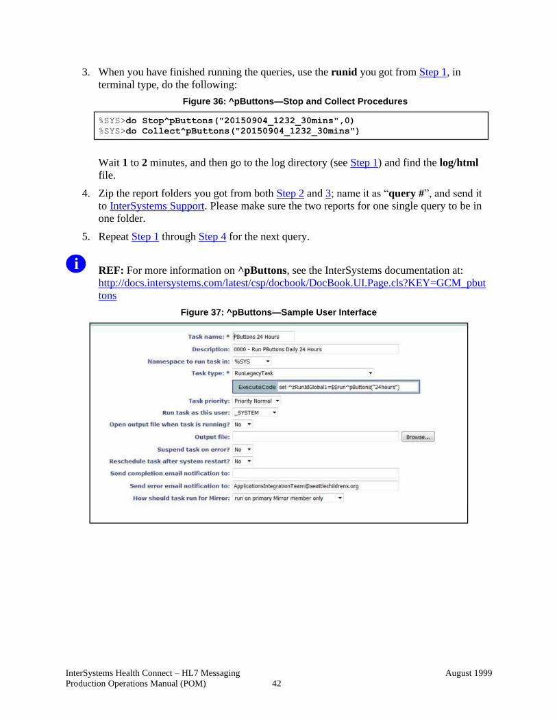
InterSystems Health Connect – HL7 Messaging
Production Operations Manual (POM)
August 1999
42
3. When you have finished running the queries, use the runid you got from Step 1, in
terminal type, do the following:
Figure 36: ^pButtons—Stop and Collect Procedures
Wait 1 to 2 minutes, and then go to the log directory (see Step 1) and find the log/html
file.
4. Zip the report folders you got from both Step 2 and 3; name it as “query #”, and send it
to InterSystems Support. Please make sure the two reports for one single query to be in
one folder.
5. Repeat Step 1 through Step 4 for the next query.
REF: For more information on ^pButtons, see the InterSystems documentation at:
http://docs.intersystems.com/latest/csp/docbook/DocBook.UI.Page.cls?KEY=GCM_pbut
tons
Figure 37: ^pButtons—Sample User Interface
%SYS>do Stop^pButtons("20150904_1232_30mins",0)
%SYS>do Collect^pButtons("20150904_1232_30mins")
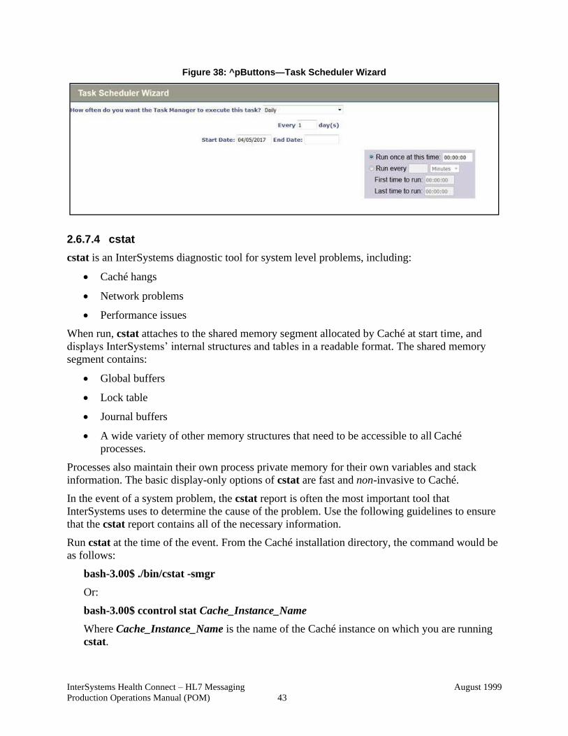
InterSystems Health Connect – HL7 Messaging
Production Operations Manual (POM)
August 1999
43
Figure 38: ^pButtons—Task Scheduler Wizard
2.6.7.4 cstat
cstat is an InterSystems diagnostic tool for system level problems, including:
• Caché hangs
• Network problems
• Performance issues
When run, cstat attaches to the shared memory segment allocated by Caché at start time, and
displays InterSystems’ internal structures and tables in a readable format. The shared memory
segment contains:
• Global buffers
• Lock table
• Journal buffers
• A wide variety of other memory structures that need to be accessible to all Caché
processes.
Processes also maintain their own process private memory for their own variables and stack
information. The basic display-only options of cstat are fast and non-invasive to Caché.
In the event of a system problem, the cstat report is often the most important tool that
InterSystems uses to determine the cause of the problem. Use the following guidelines to ensure
that the cstat report contains all of the necessary information.
Run cstat at the time of the event. From the Caché installation directory, the command would be
as follows:
bash-3.00$ ./bin/cstat -smgr
Or:
bash-3.00$ ccontrol stat Cache_Instance_Name
Where Cache_Instance_Name is the name of the Caché instance on which you are running
cstat.
InterSystems Health Connect – HL7 Messaging
Production Operations Manual (POM)
August 1999
44
NOTE: The command sample above runs the basic default output of cstat.
If the system gets hung, verify the following steps:
1. Verify the user has admin rights.
2. Locate the CacheHung script. This script is an operating system (OS) tool used to collect
data on the system when a Caché instance is hung. This script is located in the following
directory:
<instance-install-dir>/bin
REF: For a list of VistA instances by region, see the
HC_HL_App_Server_Standards_All_Regions_MASTER.xlsx Microsoft®
Excel document located at: http://go.va.gov/sxcu.
3. Execute the following command:
cstat -e2 -f-1 -m-1 -n3 -j5 -g1 -L1 -u-1 -v1 -p-1 -c-1 -q1 -w2 -E-1 -N65535
4. Check for cstat output files (.txt files). CacheHung generates cstat output files that are
often very large, in which case they are saved to separate .txt files. Remember to check
for these files when collecting the output.
REF: For more information on cstat, see InterSystems’ Monitoring Caché Using the
cstat Utility (DocBook):
http://docs.intersystems.com/latest/csp/docbook/DocBook.UI.Page.cls?KEY=GCM_cstat
2.6.7.5 mgstat
mgstat is an InterSystems diagnostic tool.
REF: For more information on mgstat, see InterSystems’ documentation at:
http://docs.intersystems.com/latest/csp/docbook/DocBook.UI.Page.cls?KEY=GCM_mgst
at
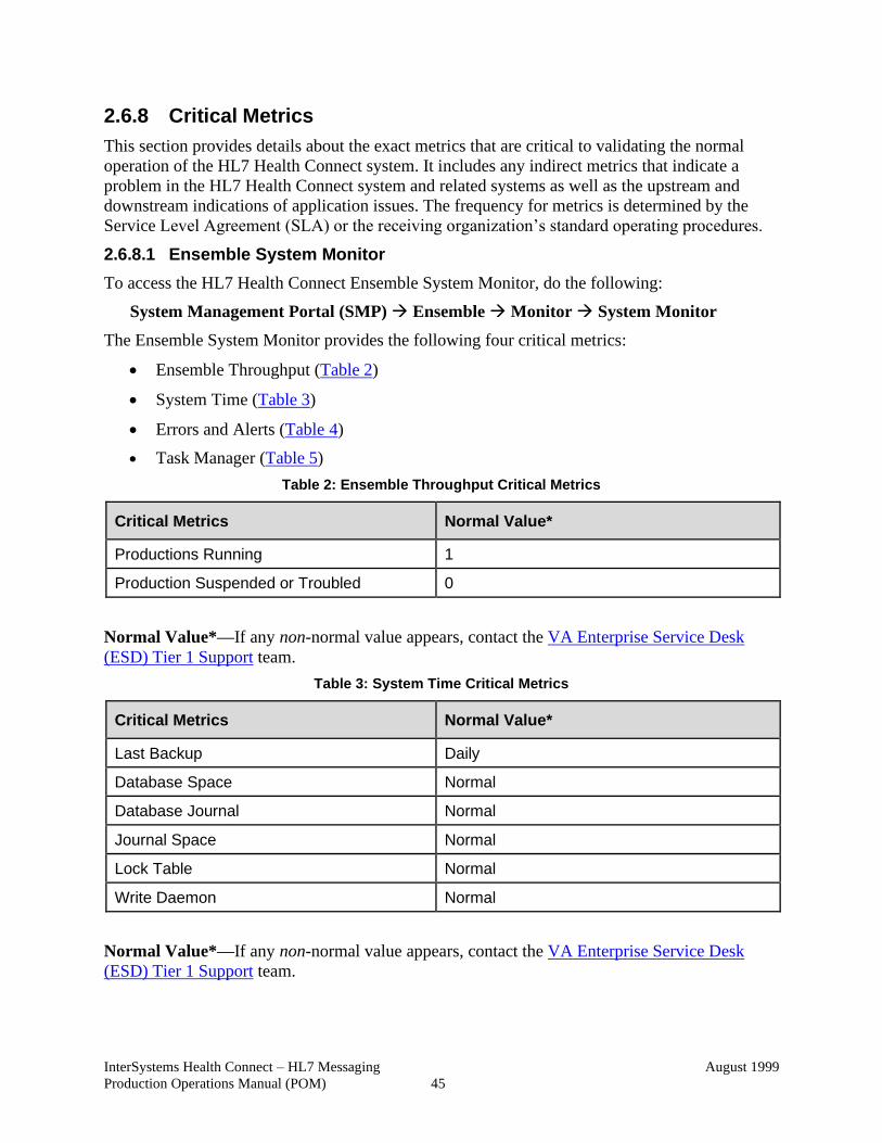
InterSystems Health Connect – HL7 Messaging
Production Operations Manual (POM)
August 1999
45
2.6.8 Critical Metrics
This section provides details about the exact metrics that are critical to validating the normal
operation of the HL7 Health Connect system. It includes any indirect metrics that indicate a
problem in the HL7 Health Connect system and related systems as well as the upstream and
downstream indications of application issues. The frequency for metrics is determined by the
Service Level Agreement (SLA) or the receiving organization’s standard operating procedures.
2.6.8.1 Ensemble System Monitor
To access the HL7 Health Connect Ensemble System Monitor, do the following:
System Management Portal (SMP) → Ensemble → Monitor → System Monitor
The Ensemble System Monitor provides the following four critical metrics:
• Ensemble Throughput (Table 2)
• System Time (Table 3)
• Errors and Alerts (Table 4)
• Task Manager (Table 5)
Table 2: Ensemble Throughput Critical Metrics
Critical Metrics Normal Value*
Productions Running 1
Production Suspended or Troubled 0
Normal Value*—If any non-normal value appears, contact the VA Enterprise Service Desk
(ESD) Tier 1 Support team.
Table 3: System Time Critical Metrics
Critical Metrics Normal Value*
Last Backup Daily
Database Space Normal
Database Journal Normal
Journal Space Normal
Lock Table Normal
Write Daemon Normal
Normal Value*—If any non-normal value appears, contact the VA Enterprise Service Desk
(ESD) Tier 1 Support team.
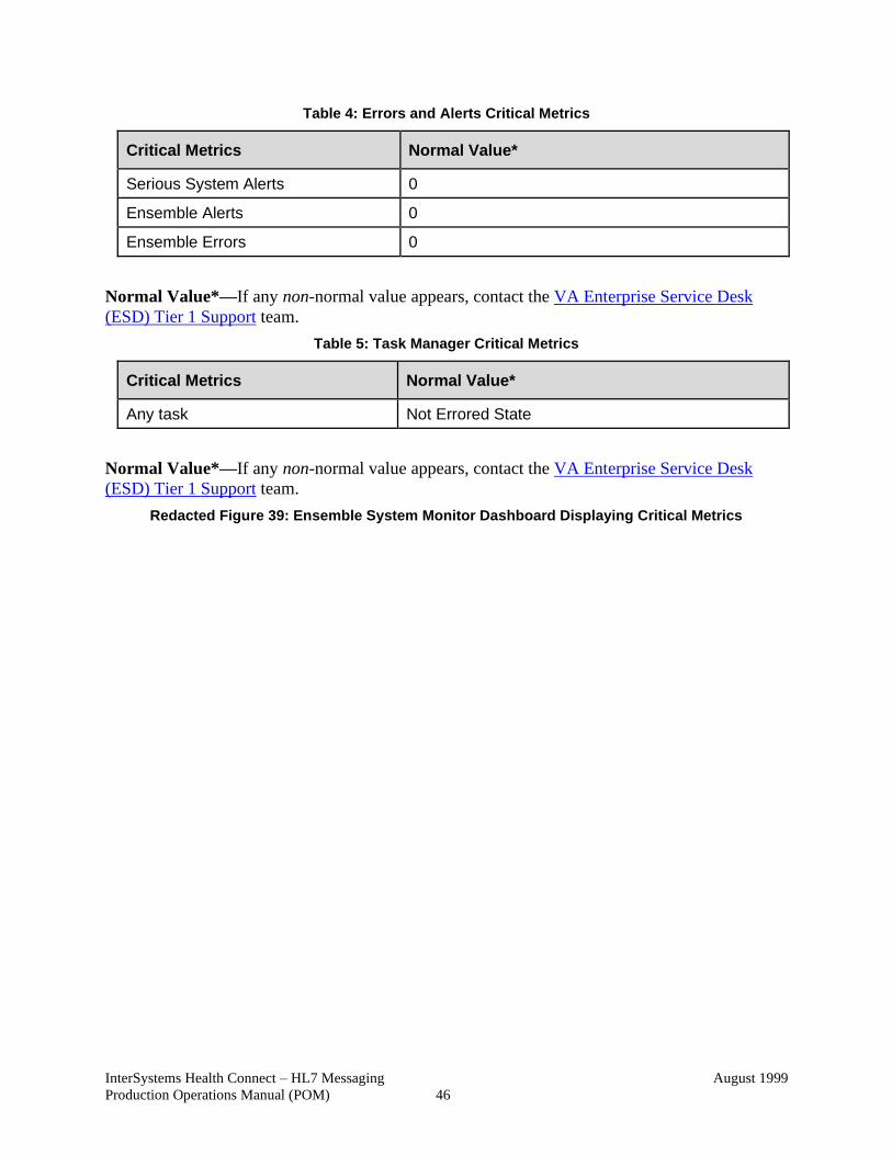
InterSystems Health Connect – HL7 Messaging
Production Operations Manual (POM)
August 1999
46
Table 4: Errors and Alerts Critical Metrics
Critical Metrics Normal Value*
Serious System Alerts 0
Ensemble Alerts 0
Ensemble Errors 0
Normal Value*—If any non-normal value appears, contact the VA Enterprise Service Desk
(ESD) Tier 1 Support team.
Table 5: Task Manager Critical Metrics
Critical Metrics Normal Value*
Any task Not Errored State
Normal Value*—If any non-normal value appears, contact the VA Enterprise Service Desk
(ESD) Tier 1 Support team.
Redacted Figure 39: Ensemble System Monitor Dashboard Displaying Critical Metrics
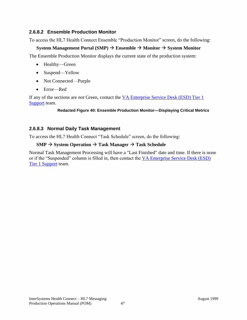
InterSystems Health Connect – HL7 Messaging
Production Operations Manual (POM)
August 1999
47
2.6.8.2 Ensemble Production Monitor
To access the HL7 Health Connect Ensemble “Production Monitor” screen, do the following:
System Management Portal (SMP) → Ensemble → Monitor → System Monitor
The Ensemble Production Monitor displays the current state of the production system:
• Healthy—Green
• Suspend—Yellow
• Not Connected—Purple
• Error—Red
If any of the sections are not Green, contact the VA Enterprise Service Desk (ESD) Tier 1
Support team.
Redacted Figure 40: Ensemble Production Monitor—Displaying Critical Metrics
2.6.8.3 Normal Daily Task Management
To access the HL7 Health Connect “Task Schedule” screen, do the following:
SMP → System Operation → Task Manager → Task Schedule
Normal Task Management Processing will have a "Last Finished" date and time. If there is none
or if the “Suspended” column is filled in, then contact the VA Enterprise Service Desk (ESD)
Tier 1 Support team.
InterSystems Health Connect – HL7 Messaging
Production Operations Manual (POM)
August 1999
48
Redacted Figure 41: Normal Daily Task Management Critical Metrics
2.6.8.4 System Console Log
To access the HL7 Health Connect “View Console Log” screen, do the following:
SMP → System Logs → Console Log
The Console Log should be reviewed for abnormal or crashed situations. For example:
Redacted Figure 42: System Console Log Critical Metrics—Sample Alerts
REF: For more information on the Console Log, see the “Monitoring System Alerts” and
“Console Log Page” sections.
2.6.8.5 Application Error Logs
To access the HL7 Health Connect “Application Error Logs” screen, do the following:
SMP → System Operation → System Logs → Application Error Logs
For any application, all application errors are logged in the Application Error Log.
REF: For sample screen images and more information on the Application Error Logs, see
the “Application Error Logs” section.
InterSystems Health Connect – HL7 Messaging
Production Operations Manual (POM)
August 1999
49
2.7 Routine Updates, Extracts, and Purges
This section defines the procedures for typical maintenance activities of the HL7 Health Connect
system, such as updates, on-request or periodic data extracts, database reorganizations, purges of
data, and triggering events.
2.7.1 Purge Management Data
2.7.1.1 Ensemble Message Purging
Ensemble Message Purging is an automatic system setup step, and if necessary, the message
purging can be done manually by following the subsequent steps:
SMP → Ensemble → Manage → Purge Management Data
Figure 43: Manually Purge Management Data
InterSystems Health Connect – HL7 Messaging
Production Operations Manual (POM)
August 1999
50
2.7.1.2 Purge Journal Files
The /Journal file system can begin to fill up rapidly with cache journal files for any number of
reasons. When this occurs, it is often desirable to purge unneeded journal files in advance of
having the /Journal file system fill up and switch to the /AltJournal file system.
NOTE: Purging journal files is not required for transaction rollbacks or crash recovery.
To purge Journal files, do any of the following procedures:
• Procedure: Manually, from cache terminal, do the following:
a. Run zn "%SYS".
b. do PURGE^JOURNAL.
c. Select Option 1 - Purge any journal.
NOTE: This is not required for transaction rollback or crash recovery.
d. When returned to the “Option?” prompt simply press Enter to exit.
e. Halt.
• Procedure: Create an on demand task:
a. In the System Management Portal (SMP) navigate to the following:
System → Operation → Task Manager → New Task
b. For each label in the Task Scheduler Wizard enter the content described below:
• Task Name: Purge Journal On Demand
• Description: Purge Journal On Demand
• Namespace to run task in: %SYS
• Task Type: RunLegacyTask
• ExecuteCode: do ##class(%SYS.Journal.File).PurgeAll()
• Task priority: Priority Normal
• Run task as this user: <chose system user> (e.g., ensusr or healthshare).
• Open output file when task is running: No
• Output file: <leave blank>
• Suspend task on error: No
• Reschedule task after system restart: No
• Send completion email notification to: <leave blank>
InterSystems Health Connect – HL7 Messaging
Production Operations Manual (POM)
August 1999
51
• Send email error notification to: <choose distribution list>
(e.g., [email protected] or
• Click Next at the bottom of the screen:
How often do you want the Task Manager to execute this task: On Demand
• Click Finish at the bottom of the screen.
• To run the on demand task in the Management Portal navigate to the following:
System → Operation → Task Manager → On-demand Task
• Find the task named Purge Journal On Demand
• Click the Run link beside the task name.
• Procedure: Create a scheduled task:
• It is possible but not recommended to create a purge journal task to run on a
schedule.
• Simply follow the steps above but rather than choose the following:
How often do you want the Task Manager to execute this task: On Demand
Instead choose a schedule from the variety of choices available.
NOTE: When purging journals using methods described here can produce Journal
Purge errors in the cconsole.log when the nightly purge journal task runs. This happens
because the nightly purge tracks journal file names and the number of days retention
expected for those journals. When purged before expected the cconsole.log reflects the
errors.
CAUTION: Real journal errors can be mistaken for these errors caused by the early purging of journals. Use caution not to become desensitized to these messages and overlook real unexpected errors.
2.7.1.3 Purge Audit Database
The HL7 Health Connect purge audit database process is TBD.
2.7.1.4 Purge Task
The HL7 Health Connect purge task process is TBD.
2.7.1.5 Purge Error and Log Files
The HL7 Health Connect purge error and log files process is TBD.
InterSystems Health Connect – HL7 Messaging
Production Operations Manual (POM)
August 1999
52
2.8 Scheduled Maintenance
This section defines the maintenance schedule for HL7 Health Connect. It includes time intervals
(e.g., yearly, quarterly, and monthly) and what must be done at each interval. It provides full
procedures for each interval and a time estimate for the duration of the system outage. It also
defines any processes for scheduling ad-hoc maintenance windows.
2.8.1 Switch Journaling Back from AltJournal to Journal
HealthShare has a built-in safe guard so that when journaling fills up the /Journal file system it
will automatically switch over the /AltJournal file system. This prevents system failures and
allows processing to continue until the situation can be resolved. Once journaling switches from
/Journal to /AltJournal it will not switch back automatically. However, the procedure for
switching back to the normal state is quite simple once the space issue is resolved.
To switch journaling back from AltJournal to Journal, do the following:
1. Prepare for switching journaling back from AltJournal to Journal by freeing the disk
space on the /Journal file system:
a. Follow the procedure in Section 2.7.1.2, “Purge Journal Files,” for purging all
journals.
NOTE: This is not required for transaction rollbacks or crash recovery.
b. Verify that this procedure worked and has freed a significant amount of space on the
original /Journal file system using the Linux terminal, enter either of the following
commands:
df –h
Or
df -Ph | column –t
c. If for any reason the procedure for purging journals does not work, then consult with
an InterSystems Support representative before proceeding.
d. In a state of emergency, it is possible to manually remove the files from the /Journal
file system, but use caution, because it is possible to create problems with the normal
scheduled journal purge in which case you will need to consult with an InterSystems
Support representative to correct that problem. However, it is a correctible problem.
Using a Linux terminal, change directories by entering the following command:
cd /<journal>
Where <journal> is the name of the primary journal file system (e.g.,
/Journal). Run the following command:
CAUTION: Use the following command with extreme care:
rm -i *
InterSystems Health Connect – HL7 Messaging
Production Operations Manual (POM)
August 1999
53
Once this step is complete, the actual switch is relatively simple.
2. To switching journaling back from AltJournal to Journal, do the following:
a. In the Management Portal navigate to the following:
System Administration → Configuration → System Configuration →
Journal Settings
b. Make note of the contents of both the Primary journal directory and the Secondary
journal directory entry (these should never be the same path).
c. Click on the path in the Primary journal directory field and modify the path to match
the Secondary journal directory path.
d. Click Save. This automatically forces a journal switch and the Primary journal
directory resumes control of where the journal files are placed.
e. Navigate into the Journal Settings a second time and modify the Primary journal
directory path back to the original path you noted above.
f. Click Save. This automatically forces a journal switch and the Primary journal
directory is now the original path and journal files will assume writing in the
/Journal file system.
g. Verify that the current journal file is being written to the original
/Journal file system.
CAUTION: Be aware that if the /Journal file system fills up and the /AltJournal file system fills up then all journaling will cease placing the system in jeopardy of catastrophic failure. This safe guard is in place for protection but the situation should be resolved as soon as possible.
2.9 Capacity Planning
This section describes the process and procedures for performing capacity planning reviews. It
includes the:
• Schedule for the reviews.
• Method for collecting the data.
• Who performs the reviews.
• How the results of the review will be presented.
• Who will be responsible for adjusting the system’s capacity.
The HL7 Health Connect capacity planning process is TBD.
2.9.1 Initial Capacity Plan
This section provides an initial capacity plan that forecasts for the first 3-month period and a 12-
month period of production.
The HL7 Health Connect initial capacity plan is TBD.
InterSystems Health Connect – HL7 Messaging
Production Operations Manual (POM)
August 1999
54
3 Exception Handling This section provides a high-level overview of how the HL7 Health Connect system problems
are handled. It describes the expectations for how administrators and other operations personnel
will respond to and handle system problems. It defines the types of issues that operators and
administrators should resolve and the types of issues that must be escalated.
The subsections below provide information necessary to detect and resolve system and
application problems. These subsections should be considered the minimum set.
3.1 Routine Errors
Like most systems, HL7 Health Connect messaging may generate a small set of errors that may
be considered routine, in the sense that they have minimal impact on the user and do not
compromise the operational state of the system. Most of the errors are transient in nature and
only require the user to retry an operation. The following subsections describe these errors, their
causes, and what, if any, response an operator needs to take.
While the occasional occurrence of these errors may be routine, getting a large number of an
individual error over a short period of time is an indication of a more serious problem. In that
case the error needs to be treated as an exceptional condition.
The following subsections are three general categories of errors that typically generate these
kinds of errors.
3.1.1 Security Errors
This section lists all security type errors that a user or operator may encounter. It lists each
individual error, with a description of what it is, when it may occur, and what the appropriate
response to the error should be.
Security errors can vary for a project/product.
REF: For Security type errors specific to a product, see the list of products in the
“Appendix A—Products Migrating from VIE to HL7 Health Connect” section.
3.1.2 Time-Outs
This section lists all time-out type errors that a user or operator may encounter. It lists each
individual error, with a description of what it is, when it may occur, and what the appropriate
response to the error should be.
Time-outs involve csp gateway time outs and connection timeout defined in an ensemble
production. Time-Out type errors can vary for a project/product.
REF: For Time-Outs type errors specific to a product, see the list of products in the
“Appendix A—Products Migrating from VIE to HL7 Health Connect” section.
InterSystems Health Connect – HL7 Messaging
Production Operations Manual (POM)
August 1999
55
3.1.3 Concurrency
This section lists all concurrency type errors that a user or operator may encounter. It lists each
individual error, with a description of what it is, when it may occur, and what the appropriate
response to the error should be.
NOTE: This section does not apply to HL7 Health Connect.
3.2 Significant Errors
Significant errors can be defined as errors or conditions that affect the system stability,
availability, performance, or otherwise make the system unavailable to its user base. The
following subsections contain information to aid administrators, operators, and other support
personnel in the resolution of significant errors, conditions, or other issues.
REF: For significant errors or conditions that affect the system stability, see Section
2.6.8, “Critical Metrics.”
3.2.1 Application Error Logs
This section describes the error logging functionality, the locations where logs are stored, and
what, if any, special tools are needed to view the log entries. For each log, it describes the
maximum size, growth rate, rotation, and retention policy. It also identifies any error or alarm
messages the system sends to external systems.
To access application error logs, do the following:
SMP → System Operation → System Logs → Application Error Logs
For any application all Application errors are logged in the Application Error Log.
The Operator would select one of the items in the table, as shown in Figure 44:
Redacted Figure 44: Application Error Logs Screen
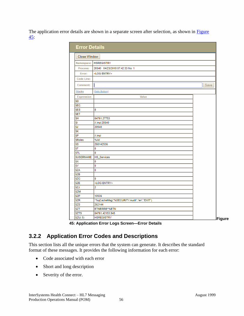
InterSystems Health Connect – HL7 Messaging
Production Operations Manual (POM)
August 1999
56
The application error details are shown in a separate screen after selection, as shown in Figure
45:
Figure 45: Application Error Logs Screen—Error Details
3.2.2 Application Error Codes and Descriptions
This section lists all the unique errors that the system can generate. It describes the standard
format of these messages. It provides the following information for each error:
• Code associated with each error
• Short and long description
• Severity of the error.
InterSystems Health Connect – HL7 Messaging
Production Operations Manual (POM)
August 1999
57
• Possible response to the error:
• HL7 Health Connect can contain many application errors. Use the following path to
access the Application Error Logs:
SMP → System Operation → System Logs → Application Error Logs
If applicable, you should perform an analysis for each error.
• For any application all Application errors are logged in the Application Error Log.
• The Operator would select one of the items from the table shown in Figure 44. The
details will be shown on this screen shot after selection (see Figure 45).
3.2.3 Infrastructure Errors
VA IT systems rely on various infrastructure components, as defined for HL7 Health Connect
system in the Logical and Physical Descriptions section of this document. Most, if not all, of
these infrastructure components generate their own sets of errors. Each component has its own
subsection below that describes how errors are reported.
3.2.3.1 Database
This section describes the system- or application-specific implementation of the database
configuration as it relates to errors, error reporting, and other pertinent information about causes
and remedies for database errors.
To manage databases in the intersystem document, see the InterSystems’ Maintaining Local
Databases documentation at:
http://docs.intersystems.com/latest/csp/docbook/DocBook.UI.Page.cls?KEY=GSA_manage#GS A_manage_databases
If a tech needs to expand the database, contact the InterSystems Support team.
REF: For Database usage for specific products, see the list of products in the “Appendix A—
Products Migrating from VIE to HL7 Health Connect” section.
3.2.3.2 Web Server
This section describes the system- or application-specific implementation of the Web server
configuration as it relates to errors, error reporting, and other pertinent information about causes
of and remedies for Web server errors.
REF: For Web Server usage for specific products, see the list of products in the
“Appendix A—Products Migrating from VIE to HL7 Health Connect” section.
3.2.3.3 Application Server
This section describes the system- or application-specific implementation of the application
server configuration as it relates to errors, error reporting, and other pertinent information about
causes of and remedies for application server errors.
InterSystems Health Connect – HL7 Messaging
Production Operations Manual (POM)
August 1999
58
REF: For Application Server usage for specific products, see the list of products
in the “Appendix A—Products Migrating from VIE to HL7 Health Connect” section.
3.2.3.4 Network
This section describes the system- or application-specific implementation of the network
configuration as it relates to errors, error reporting, and other pertinent information on causes and
remedy of network errors.
NOTE: This section is not applicable for HL7 Health Connect at the current time.
3.2.3.5 Authentication & Authorization
This section describes the system- or application-specific implementation of the authentication
and authorization component(s) as it relates to errors, error reporting, and other pertinent
information about causes of and remedies for errors.
The HL7 Health Connect authentication and authorization follows the same model as in Section
2.4, “Security / Identity Management.”
3.2.3.6 Logical and Physical Descriptions
This section includes the logical and physical descriptions of the HL7 Health Connect system.
REF: For logical and physical descriptions for specific products, see the list of products
in the “Appendix A—Products Migrating from VIE to HL7 Health Connect” section.
3.3 Dependent System(s)
This section lists any systems dependent on HL7 Health Connect. It describes the errors and
error reporting as it relates to these systems, and what remedies are available to administrators
for the resolution of these errors.
The HL7 Health Connect dependent systems are TBD.
3.4 Troubleshooting
This section provides any helpful information on troubleshooting that has been learned as part of
the development and testing processes, or from the operation of similar systems.
For troubleshooting HL7 Health Connect, contact the InterSystems Support team.
3.5 System Recovery
The following subsections define the process and procedures necessary to restore the system to a
fully operational state after a service interruption. Each of the subsections starts at a specific
system state and ends up with a fully operational system.
The subsections defined below are typical, but not comprehensive. These sections define how to
recover from the crash of HL7 Health Connect by bringing the system to a known state and then
restarting components of the system until it is fully operational.
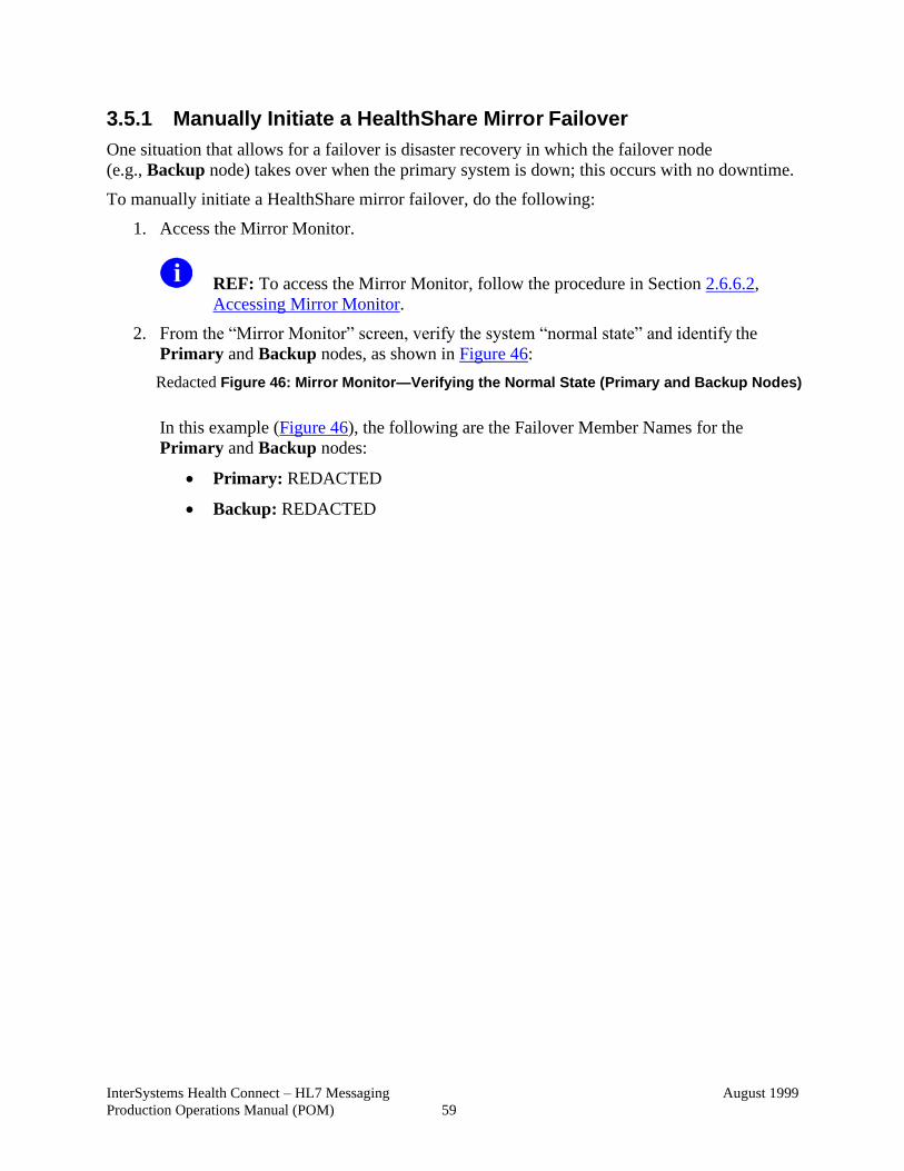
InterSystems Health Connect – HL7 Messaging
Production Operations Manual (POM)
August 1999
59
3.5.1 Manually Initiate a HealthShare Mirror Failover
One situation that allows for a failover is disaster recovery in which the failover node
(e.g., Backup node) takes over when the primary system is down; this occurs with no downtime.
To manually initiate a HealthShare mirror failover, do the following:
1. Access the Mirror Monitor.
REF: To access the Mirror Monitor, follow the procedure in Section 2.6.6.2,
Accessing Mirror Monitor.
2. From the “Mirror Monitor” screen, verify the system “normal state” and identify the
Primary and Backup nodes, as shown in Figure 46:
Redacted Figure 46: Mirror Monitor—Verifying the Normal State (Primary and Backup Nodes)
In this example (Figure 46), the following are the Failover Member Names for the
Primary and Backup nodes:
• Primary: REDACTED
• Backup: REDACTED
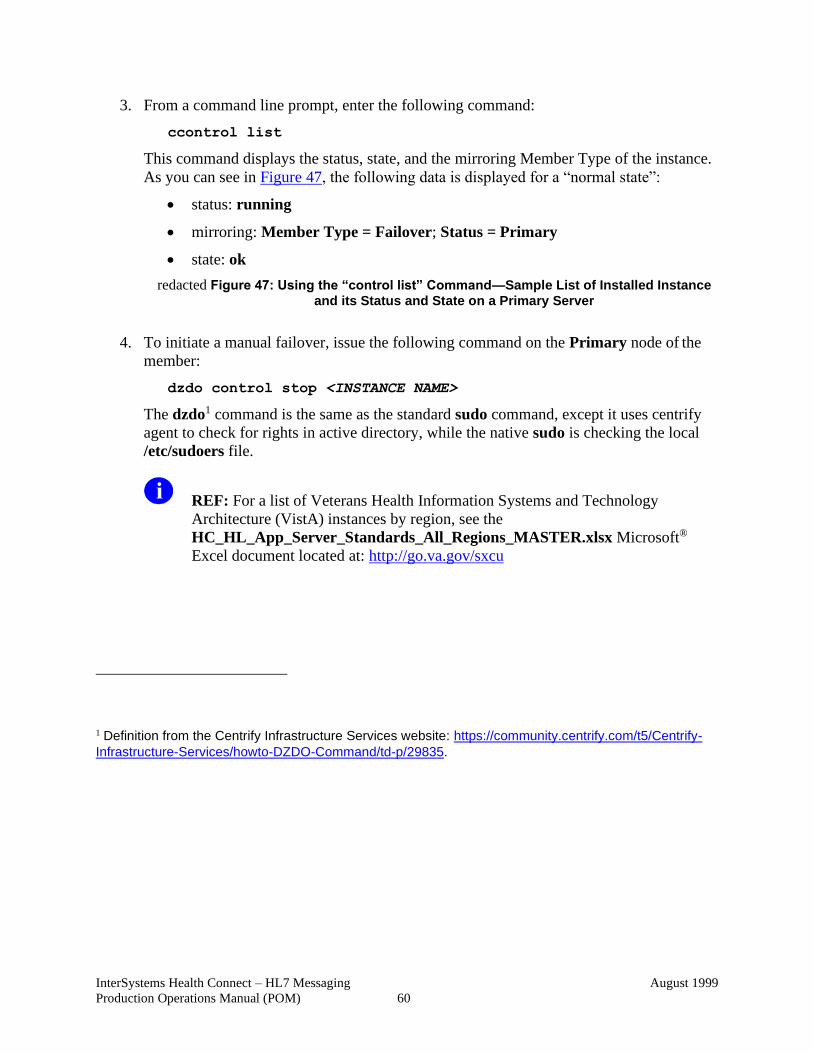
InterSystems Health Connect – HL7 Messaging
Production Operations Manual (POM)
August 1999
60
3. From a command line prompt, enter the following command:
ccontrol list
This command displays the status, state, and the mirroring Member Type of the instance.
As you can see in Figure 47, the following data is displayed for a “normal state”:
• status: running
• mirroring: Member Type = Failover; Status = Primary
• state: ok
redacted Figure 47: Using the “control list” Command—Sample List of Installed Instance
and its Status and State on a Primary Server
4. To initiate a manual failover, issue the following command on the Primary node of the
member:
dzdo control stop <INSTANCE NAME>
The dzdo1 command is the same as the standard sudo command, except it uses centrify
agent to check for rights in active directory, while the native sudo is checking the local
/etc/sudoers file.
REF: For a list of Veterans Health Information Systems and Technology
Architecture (VistA) instances by region, see the
HC_HL_App_Server_Standards_All_Regions_MASTER.xlsx Microsoft®
Excel document located at: http://go.va.gov/sxcu
1 Definition from the Centrify Infrastructure Services website: https://community.centrify.com/t5/Centrify-
Infrastructure-Services/howto-DZDO-Command/td-p/29835.
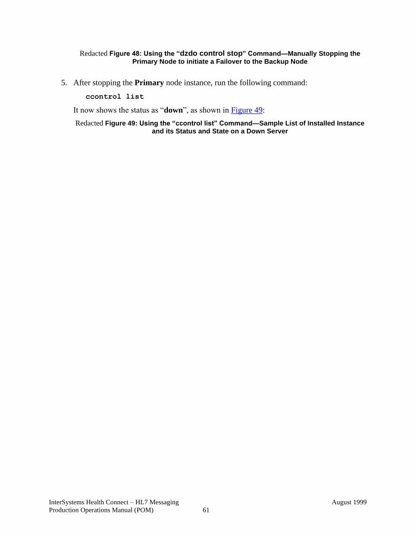
InterSystems Health Connect – HL7 Messaging
Production Operations Manual (POM)
August 1999
61
Redacted Figure 48: Using the “dzdo control stop” Command—Manually Stopping the
Primary Node to initiate a Failover to the Backup Node
5. After stopping the Primary node instance, run the following command:
ccontrol list
It now shows the status as “down”, as shown in Figure 49:
Redacted Figure 49: Using the “ccontrol list” Command—Sample List of Installed Instance and its Status and State on a Down Server
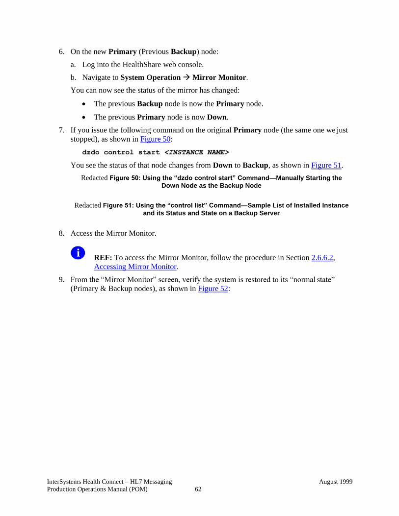
InterSystems Health Connect – HL7 Messaging
Production Operations Manual (POM)
August 1999
62
6. On the new Primary (Previous Backup) node:
a. Log into the HealthShare web console.
b. Navigate to System Operation → Mirror Monitor.
You can now see the status of the mirror has changed:
• The previous Backup node is now the Primary node.
• The previous Primary node is now Down.
7. If you issue the following command on the original Primary node (the same one we just
stopped), as shown in Figure 50:
dzdo control start <INSTANCE NAME>
You see the status of that node changes from Down to Backup, as shown in Figure 51.
Redacted Figure 50: Using the “dzdo control start” Command—Manually Starting the
Down Node as the Backup Node
Redacted Figure 51: Using the “control list” Command—Sample List of Installed Instance
and its Status and State on a Backup Server
8. Access the Mirror Monitor.
REF: To access the Mirror Monitor, follow the procedure in Section 2.6.6.2,
Accessing Mirror Monitor.
9. From the “Mirror Monitor” screen, verify the system is restored to its “normal state”
(Primary & Backup nodes), as shown in Figure 52:
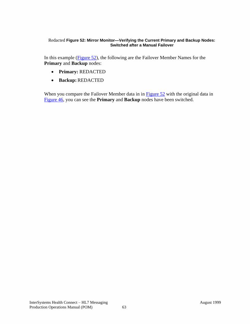
InterSystems Health Connect – HL7 Messaging
Production Operations Manual (POM)
August 1999
63
Redacted Figure 52: Mirror Monitor—Verifying the Current Primary and Backup Nodes:
Switched after a Manual Failover
In this example (Figure 52), the following are the Failover Member Names for the
Primary and Backup nodes:
• Primary: REDACTED
• Backup: REDACTED
When you compare the Failover Member data in in Figure 52 with the original data in
Figure 46, you can see the Primary and Backup nodes have been switched.
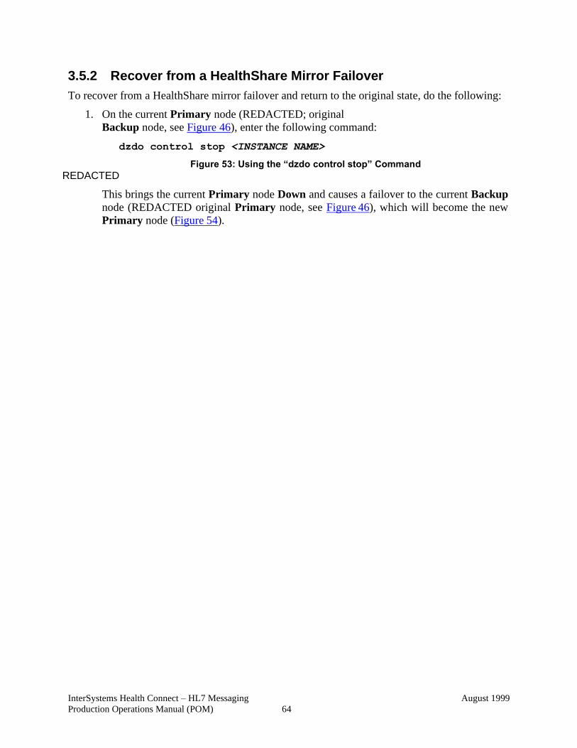
InterSystems Health Connect – HL7 Messaging
Production Operations Manual (POM)
August 1999
64
3.5.2 Recover from a HealthShare Mirror Failover
To recover from a HealthShare mirror failover and return to the original state, do the following:
1. On the current Primary node (REDACTED; original
Backup node, see Figure 46), enter the following command:
dzdo control stop <INSTANCE NAME>
Figure 53: Using the “dzdo control stop” Command
REDACTED
This brings the current Primary node Down and causes a failover to the current Backup
node (REDACTED original Primary node, see Figure 46), which will become the new
Primary node (Figure 54).
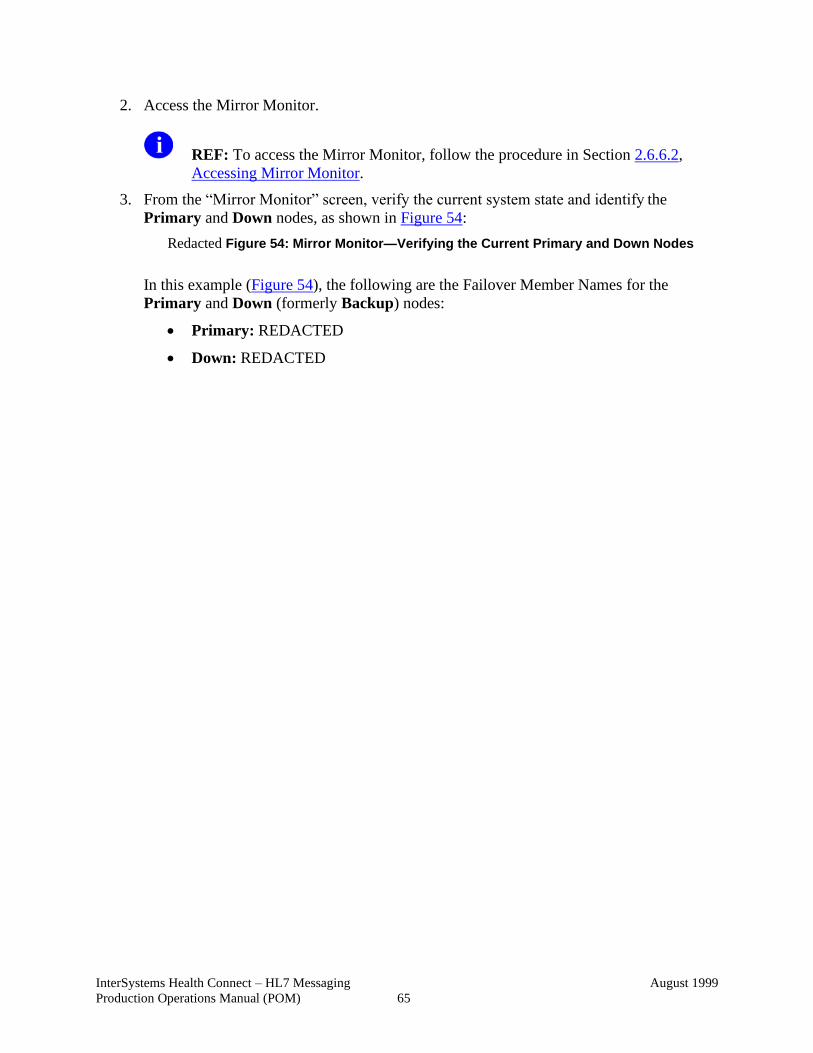
InterSystems Health Connect – HL7 Messaging
Production Operations Manual (POM)
August 1999
65
2. Access the Mirror Monitor.
REF: To access the Mirror Monitor, follow the procedure in Section 2.6.6.2,
Accessing Mirror Monitor.
3. From the “Mirror Monitor” screen, verify the current system state and identify the
Primary and Down nodes, as shown in Figure 54:
Redacted Figure 54: Mirror Monitor—Verifying the Current Primary and Down Nodes
In this example (Figure 54), the following are the Failover Member Names for the
Primary and Down (formerly Backup) nodes:
• Primary: REDACTED
• Down: REDACTED
InterSystems Health Connect – HL7 Messaging
Production Operations Manual (POM)
August 1999
66
4. On the Down node (REDACTED enter the following command:
dzdo control start <INSTANCE NAME>
Figure 55: Using the “dzdo control start” Command
REDACTED
5. This process reinstates the node as the Backup node; it is returned to the original
configuration.
Figure 56: Mirror Monitor—Verifying the Current Primary and Backup Nodes: Returned to the Original Node States after the Recovery Process
REDACTED
In this example (Figure 56), the following are the restored Failover Member Names for
the Primary and Backup nodes after the recovery process:
• Primary: REDACTED
• Backup: REDACTED
InterSystems Health Connect – HL7 Messaging
Production Operations Manual (POM)
August 1999
67
3.5.3 Restart after Non-Scheduled System Interruption
This section describes the restart of the system after the crash of the main application. It covers
the failure of other components as alternate flows to the main processes.
REF: For more information on startup, see the “System Start-Up” section.
3.5.4 Restart after Database Restore
This section describes how to restart the system after restoring from a database backup.
REF: For more information on startup, see the “System Start-Up” section.
3.5.5 Back-Out Procedures
The HL7 Health Connect Deployment and Installation Plan includes sections about Back-Out
and Rollback Procedures.
REF: For more information on back-up and restore procedures, see the “Back-Up &
Restore” section.
3.5.6 Rollback Procedures
The HL7 Health Connect Deployment and Installation Plan includes sections about Back-Out
and Rollback procedures.
The HL7 Health Connect rollback procedures are TBD.
InterSystems Health Connect – HL7 Messaging
Production Operations Manual (POM)
August 1999
68
4 Operations and Maintenance Responsibilities This section contains Table 6: HL7 Health Connect—Operations and Maintenance
Responsibilities and an attached completed Responsible, Accountable, Consulted, and Informed
(RACI) Matrix that defines the key roles required for the Operations and Maintenance (O&M) of
the HL7 Health Connect system.
The HL7 Health Connect operations and maintenance responsibilities table entries are TBD.
The RACI identifies who is responsible for key activities, such as hardware and software support
during the O&M phase of the product’s lifecycle. It includes identifying the Sustainment Support
resources.
NOTE: The RACI and POM documents are kept as separate documents located under
source control in the EHRM FM24 Documentation Rational Jazz RTC and in SharePoint
here.
• Responsible, Accountable, Consulted, and Informed (RACI)
(i.e., FM24_RACI.xlsx)
• Production Operations Manual (POM)
(i.e., HC-HL7_Messaging_1_0_POM.docx)
The POM and the RACI are “living” documents and will be updated throughout the
system lifecycle.
Table 6: HL7 Health Connect—Operations and Maintenance Responsibilities
Role & Brief
Description
Assigned Organization
(Pillar and Sub-office)
Contact Information
Tier 0: Local End User
Support
(e.g., Automated Data
Processing Application
Coordinator [ADPAC])
Local ADPAC, Veterans
Health Information
Systems and Technology
Architecture (VistA) or
Enterprise Service
designated for each Local
VAMC and or each Region
Will be for separate for each VA
Medical Center (VAMC) location.
Enterprise Service
Desk (ESD) Tier 1:
Provide first contact
resolution via
Knowledge
Documents retained in
Enterprise Service
Desk (ESD) Manager
(ServiceNow)
ITOPs (Enterprise Service
Desk [ESD]) 855-673-4357
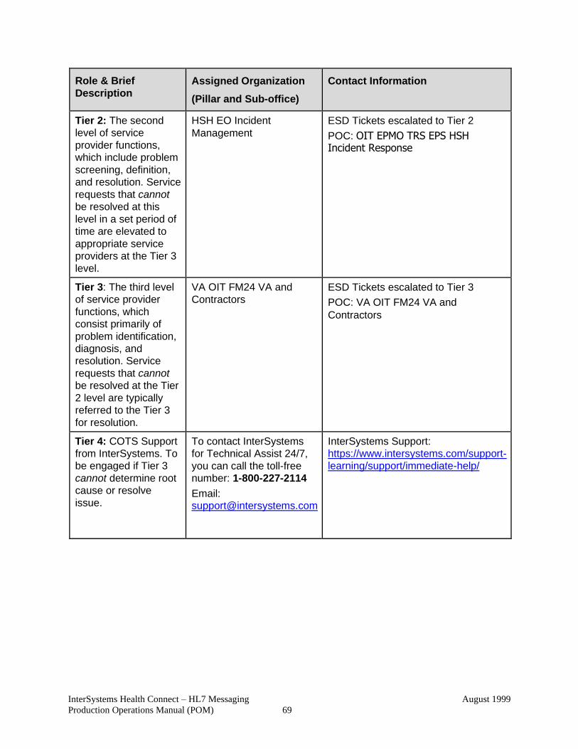
InterSystems Health Connect – HL7 Messaging
Production Operations Manual (POM)
August 1999
69
Role & Brief
Description
Assigned Organization
(Pillar and Sub-office)
Contact Information
Tier 2: The second
level of service
provider functions,
which include problem
screening, definition,
and resolution. Service
requests that cannot
be resolved at this
level in a set period of
time are elevated to
appropriate service
providers at the Tier 3
level.
HSH EO Incident
Management
ESD Tickets escalated to Tier 2
POC: OIT EPMO TRS EPS HSH Incident Response
Tier 3: The third level
of service provider
functions, which
consist primarily of
problem identification,
diagnosis, and
resolution. Service
requests that cannot
be resolved at the Tier
2 level are typically
referred to the Tier 3
for resolution.
VA OIT FM24 VA and
Contractors
ESD Tickets escalated to Tier 3
POC: VA OIT FM24 VA and
Contractors
Tier 4: COTS Support
from InterSystems. To
be engaged if Tier 3
cannot determine root
cause or resolve
issue.
To contact InterSystems
for Technical Assist 24/7,
you can call the toll-free
number: 1-800-227-2114
Email: [email protected]
InterSystems Support:
https://www.intersystems.com/support-
learning/support/immediate-help/
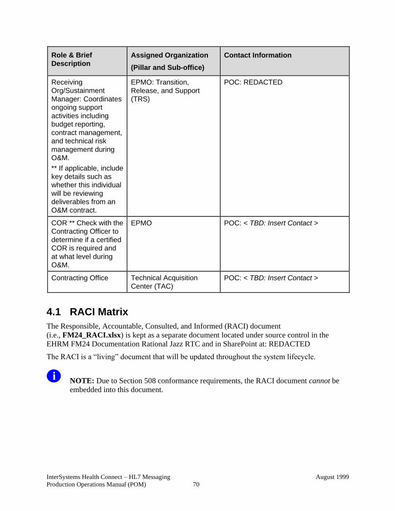
InterSystems Health Connect – HL7 Messaging
Production Operations Manual (POM)
August 1999
70
Role & Brief
Description
Assigned Organization
(Pillar and Sub-office)
Contact Information
Receiving
Org/Sustainment
Manager: Coordinates
ongoing support
activities including
budget reporting,
contract management,
and technical risk
management during
O&M.
** If applicable, include
key details such as
whether this individual
will be reviewing
deliverables from an
O&M contract.
EPMO: Transition,
Release, and Support
(TRS)
POC: REDACTED
COR ** Check with the
Contracting Officer to
determine if a certified
COR is required and
at what level during
O&M.
EPMO POC: < TBD: Insert Contact >
Contracting Office Technical Acquisition
Center (TAC)
POC: < TBD: Insert Contact >
4.1 RACI Matrix
The Responsible, Accountable, Consulted, and Informed (RACI) document
(i.e., FM24_RACI.xlsx) is kept as a separate document located under source control in the
EHRM FM24 Documentation Rational Jazz RTC and in SharePoint at: REDACTED
The RACI is a “living” document that will be updated throughout the system lifecycle.
NOTE: Due to Section 508 conformance requirements, the RACI document cannot be
embedded into this document.
InterSystems Health Connect – HL7 Messaging
Production Operations Manual (POM)
August 1999
71
5 Approval Signatures Signatures indicate the approval of the InterSystems HL7 Health Connect Messaging Production
Operations Manual (POM) and accompanying RACI.
Currently, there are 14 applications that will be migrated from VistA Interface Engine (VIE) to
HL7 Health Connect; so, each individual application added will require a separate “Approval
Signatures” section.
To approve and sign this POM for Outpatient Pharmacy Automation Interface (OPAI), see the
“OPAI Approval Signatures” section.
REF: For a list of all products scheduled to be migrated from VIE to HL7 Health
Connect, see the “Appendix A—Products Migrating from VIE to HL7 Health Connect”
section.
Eventually, all 14 of these applications will be added to this POM with separate
subsections (including separate approval signature blocks) in Appendix A.
InterSystems Health Connect – HL7 Messaging
Production Operations Manual (POM)
August 1999
72
6 Appendix A—Products Migrating from VIE to HL7 Health Connect
The HL7 Health Connect (HC) production system replaces the current functionality provided by
the Vitria Interface Engine (VIE), with messaging routed through the HL7 Health Connect
production system.
As the VA consolidates onto one enterprise health information interface engine, the FM 24
project team is migrating messaging from VIE to InterSystems HL7 Health Connect
(HealthShare). This effort ensures that all Veteran health information is consistent as it is shared
across the VA enterprise. Leveraging existing VA IT investments and reducing the number of
messaging platforms; therefore, driving efficiency.
Over time, the following 14 applications will be migrated from VIE to HL7 Health Connect:
• Pharmacy Automated Dispensing Equipment (PADE)
• Outpatient Pharmacy Automation Interface (OPAI)
• Laboratory Electronic Data Interchange (LEDI) / Lab Data Sharing and Interoperability
(LDSI) Lab Data
• Claims Processing & Eligibility (CPE)
• Enrollment System ESR/MVR (eGate)
• Federal Health Information Exchange (FHIE) / Bidirectional Health Information
Exchange (BHIE) / Data Sharing Interface (DSI)
• Electronic Contract Management System (eCMS)
• National Provider Identifier (NPI)
• Federal Procurement Data System (FPDS)
• Remote Order Entry System (ROES)
• Standards Terminology Service (STS)
• Transcription Services (Shadowlink, Goodwill)
• Clinical/Health Data Repository (CHDR)
• Health Data Repository (HDR)
As each application is migrated from VIE to HL7 Health Connect, a new sub-section will be
added to this Production Operations Manual (POM) appendix.
NOTE: Pharmacy Automated Dispensing Equipment (PADE) was the first application to
migrate and will be used as a template for the other applications that follow.
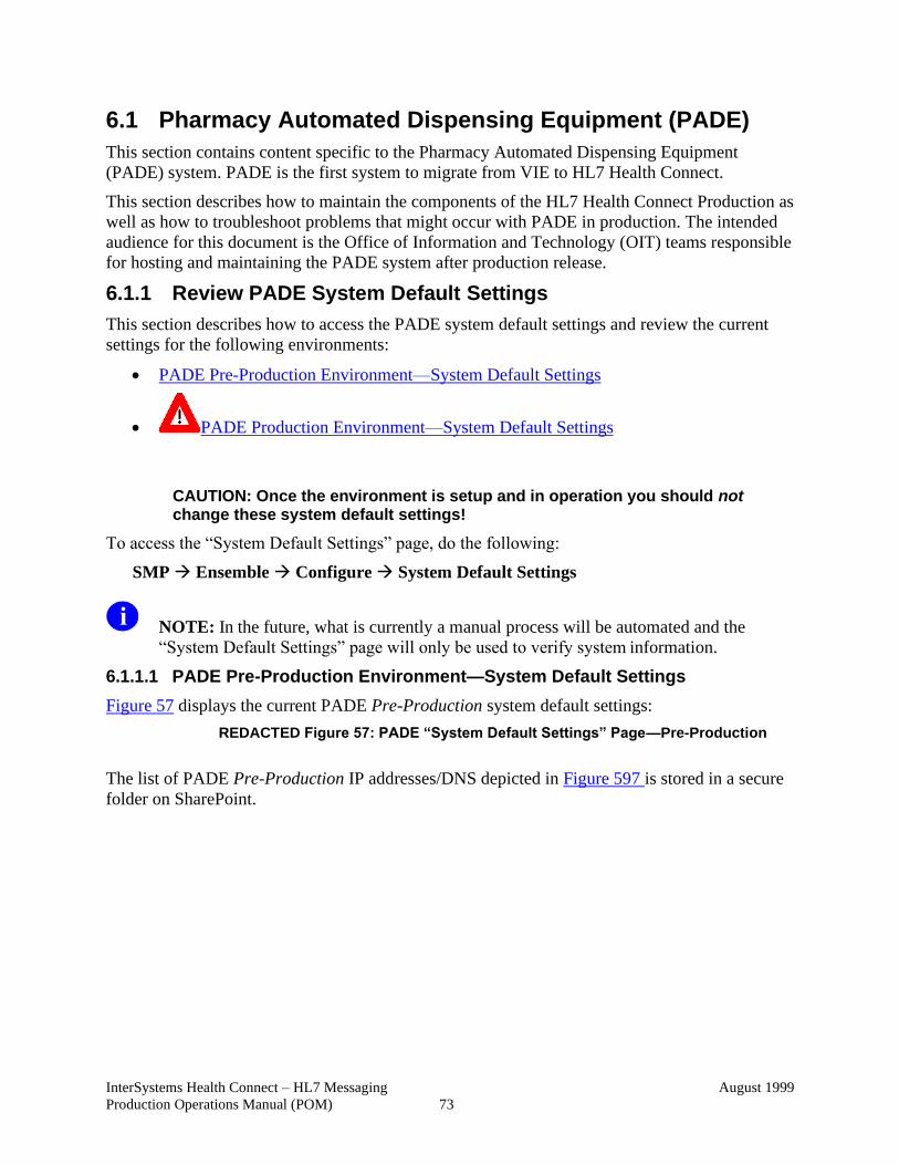
InterSystems Health Connect – HL7 Messaging
Production Operations Manual (POM)
August 1999
73
6.1 Pharmacy Automated Dispensing Equipment (PADE)
This section contains content specific to the Pharmacy Automated Dispensing Equipment
(PADE) system. PADE is the first system to migrate from VIE to HL7 Health Connect.
This section describes how to maintain the components of the HL7 Health Connect Production as
well as how to troubleshoot problems that might occur with PADE in production. The intended
audience for this document is the Office of Information and Technology (OIT) teams responsible
for hosting and maintaining the PADE system after production release.
6.1.1 Review PADE System Default Settings
This section describes how to access the PADE system default settings and review the current
settings for the following environments:
• PADE Pre-Production Environment—System Default Settings
• PADE Production Environment—System Default Settings
CAUTION: Once the environment is setup and in operation you should not change these system default settings!
To access the “System Default Settings” page, do the following:
SMP → Ensemble → Configure → System Default Settings
NOTE: In the future, what is currently a manual process will be automated and the
“System Default Settings” page will only be used to verify system information.
6.1.1.1 PADE Pre-Production Environment—System Default Settings
Figure 57 displays the current PADE Pre-Production system default settings:
REDACTED Figure 57: PADE “System Default Settings” Page—Pre-Production
The list of PADE Pre-Production IP addresses/DNS depicted in Figure 597 is stored in a secure
folder on SharePoint.
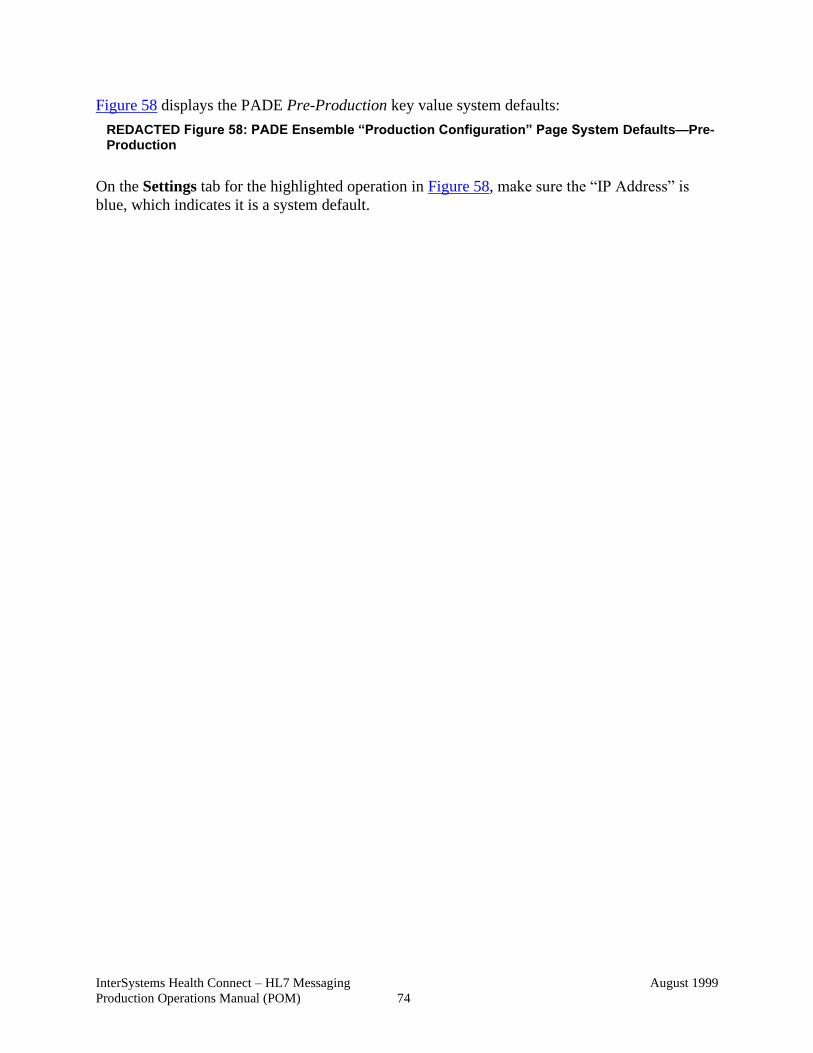
InterSystems Health Connect – HL7 Messaging
Production Operations Manual (POM)
August 1999
74
Figure 58 displays the PADE Pre-Production key value system defaults:
REDACTED Figure 58: PADE Ensemble “Production Configuration” Page System Defaults—Pre-Production
On the Settings tab for the highlighted operation in Figure 58, make sure the “IP Address” is
blue, which indicates it is a system default.
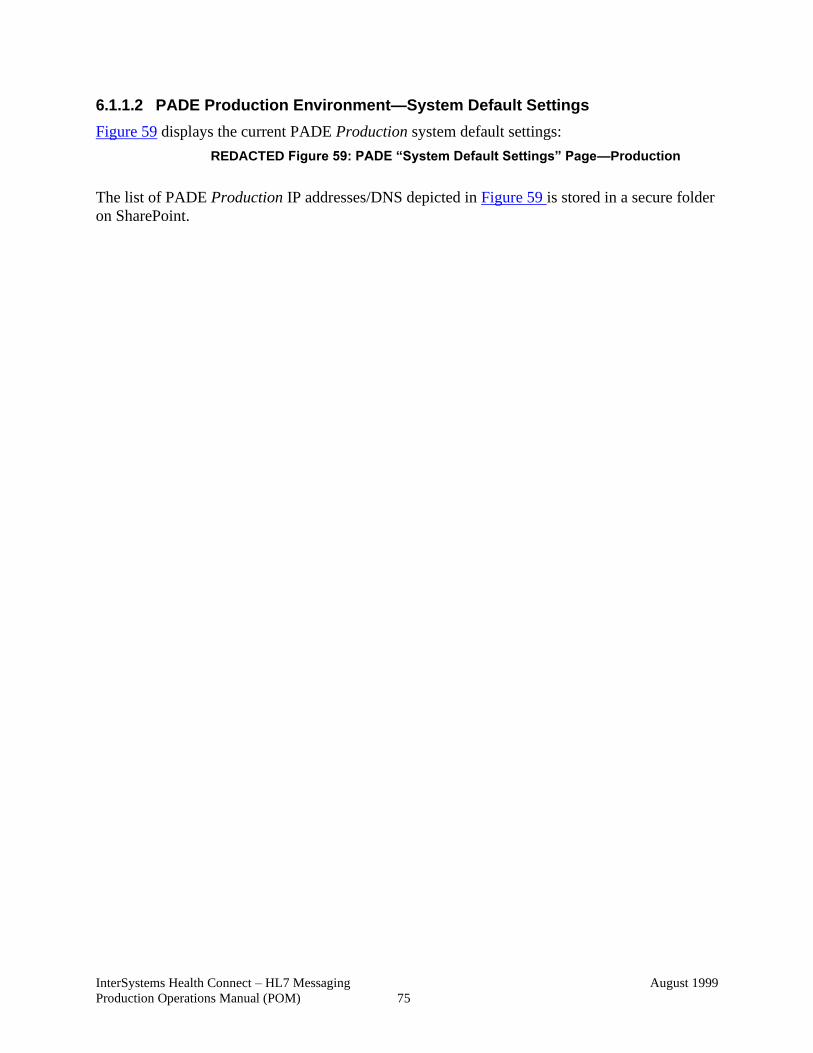
InterSystems Health Connect – HL7 Messaging
Production Operations Manual (POM)
August 1999
75
6.1.1.2 PADE Production Environment—System Default Settings
Figure 59 displays the current PADE Production system default settings:
REDACTED Figure 59: PADE “System Default Settings” Page—Production
The list of PADE Production IP addresses/DNS depicted in Figure 59 is stored in a secure folder
on SharePoint.
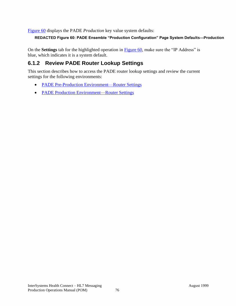
InterSystems Health Connect – HL7 Messaging
Production Operations Manual (POM)
August 1999
76
Figure 60 displays the PADE Production key value system defaults:
REDACTED Figure 60: PADE Ensemble “Production Configuration” Page System Defaults—Production
On the Settings tab for the highlighted operation in Figure 60, make sure the “IP Address” is
blue, which indicates it is a system default.
6.1.2 Review PADE Router Lookup Settings
This section describes how to access the PADE router lookup settings and review the current
settings for the following environments:
• PADE Pre-Production Environment—Router Settings
• PADE Production Environment—Router Settings
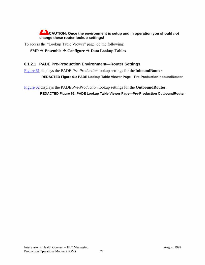
InterSystems Health Connect – HL7 Messaging
Production Operations Manual (POM)
August 1999
77
CAUTION: Once the environment is setup and in operation you should not change these router lookup settings!
To access the “Lookup Table Viewer” page, do the following:
SMP → Ensemble → Configure → Data Lookup Tables
6.1.2.1 PADE Pre-Production Environment—Router Settings
Figure 61 displays the PADE Pre-Production lookup settings for the InboundRouter:
REDACTED Figure 61: PADE Lookup Table Viewer Page—Pre-Production InboundRouter
Figure 62 displays the PADE Pre-Production lookup settings for the OutboundRouter:
REDACTED Figure 62: PADE Lookup Table Viewer Page—Pre-Production OutboundRouter
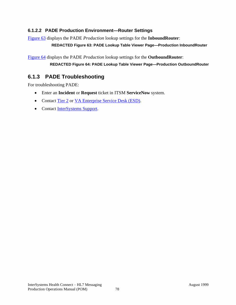
InterSystems Health Connect – HL7 Messaging
Production Operations Manual (POM)
August 1999
78
6.1.2.2 PADE Production Environment—Router Settings
Figure 63 displays the PADE Production lookup settings for the InboundRouter:
REDACTED Figure 63: PADE Lookup Table Viewer Page—Production InboundRouter
Figure 64 displays the PADE Production lookup settings for the OutboundRouter:
REDACTED Figure 64: PADE Lookup Table Viewer Page—Production OutboundRouter
6.1.3 PADE Troubleshooting
For troubleshooting PADE:
• Enter an Incident or Request ticket in ITSM ServiceNow system.
• Contact Tier 2 or VA Enterprise Service Desk (ESD).
• Contact InterSystems Support.
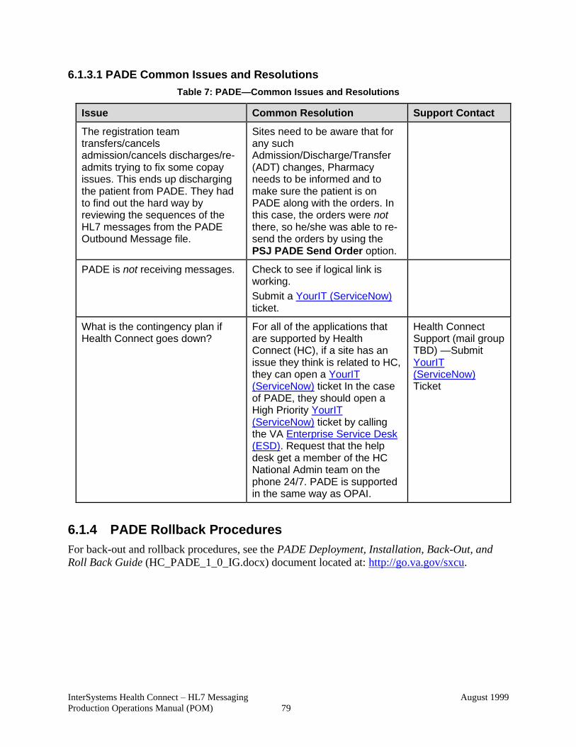
InterSystems Health Connect – HL7 Messaging
Production Operations Manual (POM)
August 1999
79
6.1.3.1 PADE Common Issues and Resolutions
Table 7: PADE—Common Issues and Resolutions
Issue Common Resolution Support Contact
The registration team transfers/cancels admission/cancels discharges/re- admits trying to fix some copay issues. This ends up discharging the patient from PADE. They had to find out the hard way by reviewing the sequences of the HL7 messages from the PADE Outbound Message file.
Sites need to be aware that for any such Admission/Discharge/Transfer (ADT) changes, Pharmacy needs to be informed and to make sure the patient is on PADE along with the orders. In this case, the orders were not there, so he/she was able to re- send the orders by using the PSJ PADE Send Order option.
PADE is not receiving messages. Check to see if logical link is working.
Submit a YourIT (ServiceNow) ticket.
What is the contingency plan if Health Connect goes down?
For all of the applications that are supported by Health Connect (HC), if a site has an issue they think is related to HC, they can open a YourIT (ServiceNow) ticket In the case of PADE, they should open a High Priority YourIT (ServiceNow) ticket by calling the VA Enterprise Service Desk (ESD). Request that the help desk get a member of the HC National Admin team on the phone 24/7. PADE is supported in the same way as OPAI.
Health Connect Support (mail group TBD) —Submit YourIT (ServiceNow) Ticket
6.1.4 PADE Rollback Procedures
For back-out and rollback procedures, see the PADE Deployment, Installation, Back-Out, and
Roll Back Guide (HC_PADE_1_0_IG.docx) document located at: http://go.va.gov/sxcu.
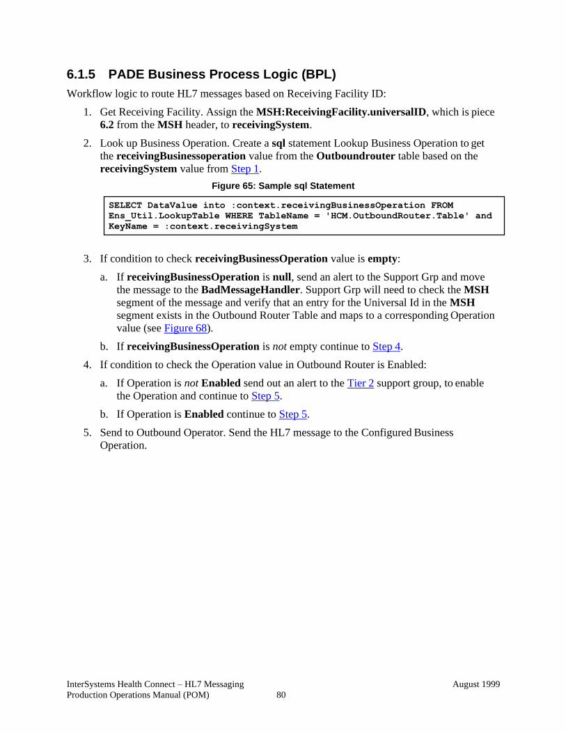
InterSystems Health Connect – HL7 Messaging
Production Operations Manual (POM)
August 1999
80
6.1.5 PADE Business Process Logic (BPL)
Workflow logic to route HL7 messages based on Receiving Facility ID:
1. Get Receiving Facility. Assign the MSH:ReceivingFacility.universalID, which is piece
6.2 from the MSH header, to receivingSystem.
2. Look up Business Operation. Create a sql statement Lookup Business Operation to get
the receivingBusinessoperation value from the Outboundrouter table based on the
receivingSystem value from Step 1.
Figure 65: Sample sql Statement
3. If condition to check receivingBusinessOperation value is empty:
a. If receivingBusinessOperation is null, send an alert to the Support Grp and move
the message to the BadMessageHandler. Support Grp will need to check the MSH
segment of the message and verify that an entry for the Universal Id in the MSH
segment exists in the Outbound Router Table and maps to a corresponding Operation
value (see Figure 68).
b. If receivingBusinessOperation is not empty continue to Step 4.
4. If condition to check the Operation value in Outbound Router is Enabled:
a. If Operation is not Enabled send out an alert to the Tier 2 support group, to enable
the Operation and continue to Step 5.
b. If Operation is Enabled continue to Step 5.
5. Send to Outbound Operator. Send the HL7 message to the Configured Business
Operation.
SELECT DataValue into :context.receivingBusinessOperation FROM
Ens_Util.LookupTable WHERE TableName = 'HCM.OutboundRouter.Table' and
KeyName = :context.receivingSystem
InterSystems Health Connect – HL7 Messaging
Production Operations Manual (POM)
August 1999
81
REDACTED Figure 66: Business Process Logic (BPL) for OutRouter
6.1.5.1 PADE Message Sample
REDACTED Figure 67: PADE—Message Sample
InterSystems Health Connect – HL7 Messaging
Production Operations Manual (POM)
August 1999
82
REDACTED Figure 68: BPL—Outbound Router Table with MSH Segment Entry to Operation: PADE
REDACTED Figure 69: BPL—Enabled Operation 999.PADE.Server
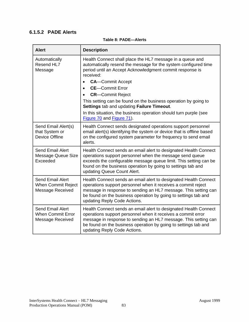
InterSystems Health Connect – HL7 Messaging
Production Operations Manual (POM)
August 1999
83
6.1.5.2 PADE Alerts
Table 8: PADE—Alerts
Alert Description
Automatically
Resend HL7
Message
Health Connect shall place the HL7 message in a queue and
automatically resend the message for the system configured time
period until an Accept Acknowledgment commit response is
received:
• CA—Commit Accept
• CE—Commit Error
• CR—Commit Reject
This setting can be found on the business operation by going to
Settings tab and updating Failure Timeout.
In this situation, the business operation should turn purple (see Figure 70 and Figure 71).
Send Email Alert(s)
that System or
Device Offline
Health Connect sends designated operations support personnel
email alert(s) identifying the system or device that is offline based
on the configured system parameter for frequency to send email
alerts.
Send Email Alert
Message Queue Size
Exceeded
Health Connect sends an email alert to designated Health Connect
operations support personnel when the message send queue
exceeds the configurable message queue limit. This setting can be
found on the business operation by going to settings tab and
updating Queue Count Alert.
Send Email Alert
When Commit Reject
Message Received
Health Connect sends an email alert to designated Health Connect
operations support personnel when it receives a commit reject
message in response to sending an HL7 message. This setting can
be found on the business operation by going to settings tab and
updating Reply Code Actions.
Send Email Alert
When Commit Error
Message Received
Health Connect sends an email alert to designated Health Connect
operations support personnel when it receives a commit error
message in response to sending an HL7 message. This setting can
be found on the business operation by going to settings tab and
updating Reply Code Actions.

InterSystems Health Connect – HL7 Messaging
Production Operations Manual (POM)
August 1999
84
REDACTED Figure 70: PADE—Alerts: Automatically Resent HL7 Message: Operations List showing PADE Server with Purple Indicator (Retrying)
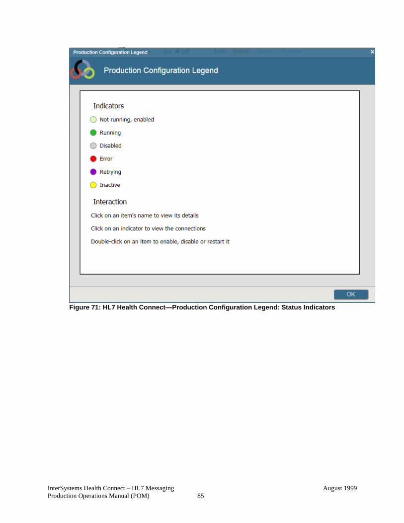
InterSystems Health Connect – HL7 Messaging
Production Operations Manual (POM)
August 1999
85
Figure 71: HL7 Health Connect—Production Configuration Legend: Status Indicators
InterSystems Health Connect – HL7 Messaging
Production Operations Manual (POM)
August 1999
86
6.1.6 PADE Approval Signatures
The signatures in this section indicate the approval of the HL7 InterSystems Health Connect
Production Operations Manual (POM) and accompanying RACI for the Pharmacy Automated
Dispensing Equipment (PADE) application.
NOTE: Digital signatures will only be added to the PDF version of the Microsoft® Word
document (i.e., HC-HL7_Messaging_1_0_POM-Signed.pdf).
REVIEW DATE: <date>
SCRIBE: <name>
Signed:
REDACTED Date
Program Manager Common Services
Signed:
REDACTED Date
Pharmacy Informatics Specialist (PBM)
Signed:
REDACTED Date
Division Chief, Application Hosting, Transition & Migration Division
InterSystems Health Connect – HL7 Messaging
Production Operations Manual (POM)
August 1999
87
6.2 Outpatient Pharmacy Automation Interface (OPAI)
This section contains content specific to the Outpatient Pharmacy Automation Interface (OPAI)
system. OPAI is the second system to migrate from VIE to HL7 Health Connect.
This section describes how to maintain the components of the HL7 Health Connect Production as
well as how to troubleshoot problems that might occur with OPAI in production. The intended
audience for this document is the Office of Information and Technology (OIT) teams responsible
for hosting and maintaining the OPAI system after production release.
6.2.1 Review OPAI System Default Settings
This section describes how to access the OPAI system default settings and review the current
settings for the following environments:
• OPAI Pre-Production Environment—System Default Settings
• OPAI Production Environment—System Default Settings
CAUTION: Once the environment is setup and in operation you should not change these system default settings!
To access the “System Default Settings” page, do the following:
SMP → Ensemble → Configure → System Default Settings
NOTE: In the future, what is currently a manual process will be automated and the
“System Default Settings” page will only be used to verify system information.
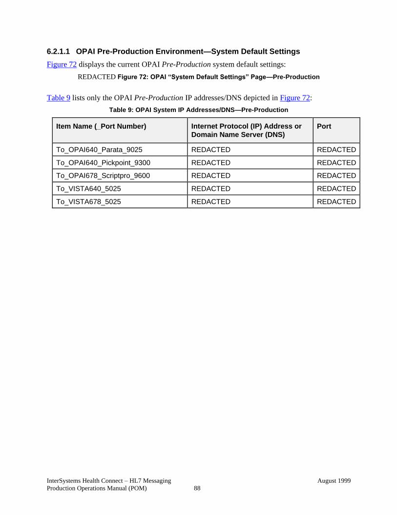
InterSystems Health Connect – HL7 Messaging
Production Operations Manual (POM)
August 1999
88
6.2.1.1 OPAI Pre-Production Environment—System Default Settings
Figure 72 displays the current OPAI Pre-Production system default settings:
REDACTED Figure 72: OPAI “System Default Settings” Page—Pre-Production
Table 9 lists only the OPAI Pre-Production IP addresses/DNS depicted in Figure 72:
Table 9: OPAI System IP Addresses/DNS—Pre-Production
Item Name (_Port Number) Internet Protocol (IP) Address or
Domain Name Server (DNS) Port
To_OPAI640_Parata_9025 REDACTED REDACTED
To_OPAI640_Pickpoint_9300 REDACTED REDACTED
To_OPAI678_Scriptpro_9600 REDACTED REDACTED
To_VISTA640_5025 REDACTED REDACTED
To_VISTA678_5025 REDACTED REDACTED
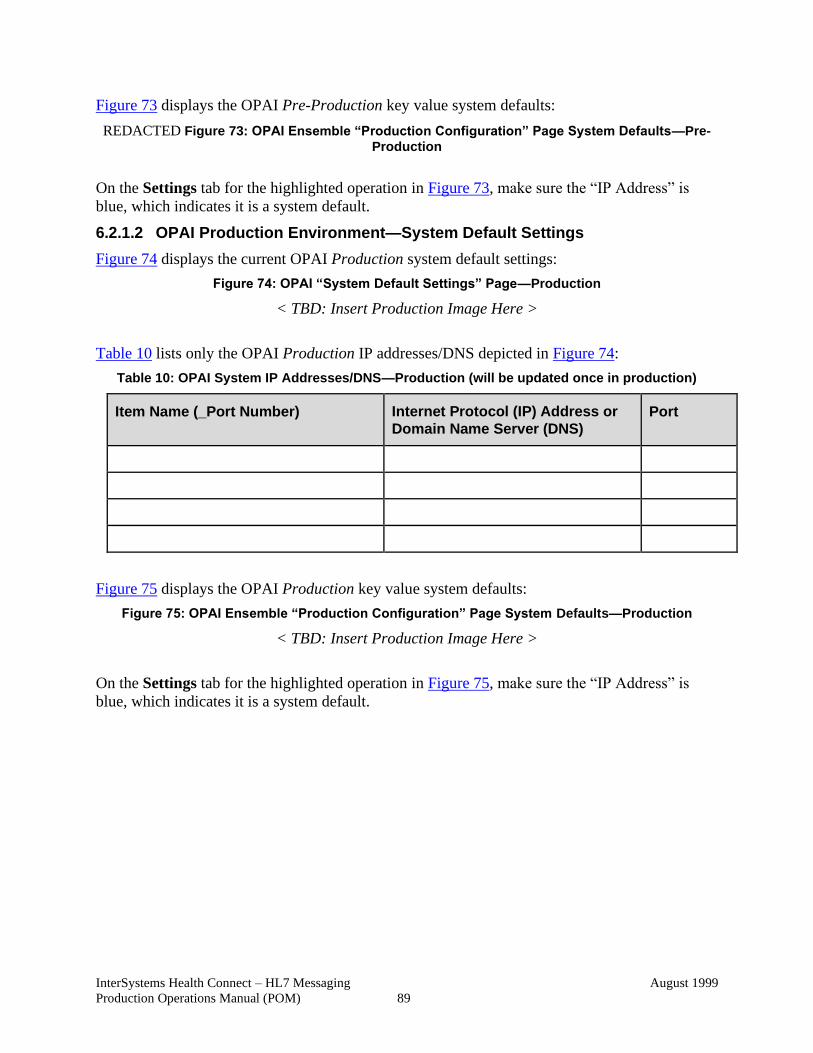
InterSystems Health Connect – HL7 Messaging
Production Operations Manual (POM)
August 1999
89
Figure 73 displays the OPAI Pre-Production key value system defaults:
REDACTED Figure 73: OPAI Ensemble “Production Configuration” Page System Defaults—Pre-
Production
On the Settings tab for the highlighted operation in Figure 73, make sure the “IP Address” is
blue, which indicates it is a system default.
6.2.1.2 OPAI Production Environment—System Default Settings
Figure 74 displays the current OPAI Production system default settings:
Figure 74: OPAI “System Default Settings” Page—Production
< TBD: Insert Production Image Here >
Table 10 lists only the OPAI Production IP addresses/DNS depicted in Figure 74:
Table 10: OPAI System IP Addresses/DNS—Production (will be updated once in production)
Item Name (_Port Number) Internet Protocol (IP) Address or
Domain Name Server (DNS)
Port
Figure 75 displays the OPAI Production key value system defaults:
Figure 75: OPAI Ensemble “Production Configuration” Page System Defaults—Production
< TBD: Insert Production Image Here >
On the Settings tab for the highlighted operation in Figure 75, make sure the “IP Address” is
blue, which indicates it is a system default.
InterSystems Health Connect – HL7 Messaging
Production Operations Manual (POM)
August 1999
90
6.2.2 Review OPAI Router Lookup Settings
This section describes how to access the OPAI router lookup settings and review the current
settings for the following environments:
• OPAI Pre-Production Environment—Router Settings
• OPAI Production Environment—Router Settings
CAUTION: Once the environment is setup and in operation you should not change these router lookup settings!
To access the “Lookup Table Viewer” page, do the following:
SMP → Ensemble → Configure → Data Lookup Tables
6.2.2.1 OPAI Pre-Production Environment—Router Settings
Figure 76 displays the OPAI Pre-Production lookup settings for the InboundRouter:
REDACTED Figure 76: OPAI Lookup Table Viewer Page—Pre-Production InboundRouter
Figure 77 displays the OPAI Pre-Production lookup settings for the OutboundRouter:
REDACTED Figure 77: OPAI Lookup Table Viewer Page—Pre-Production OutboundRouter
6.2.2.2 OPAI Production Environment—Router Settings
Figure 78 displays the OPAI Production lookup settings for the InboundRouter:
Figure 78: OPAI Lookup Table Viewer Page—Production InboundRouter
< TBD: Insert Production Image Here >
Figure 79 displays the OPAI Production lookup settings for the OutboundRouter:
Figure 79: OPAI Lookup Table Viewer Page—Production OutboundRouter
< TBD: Insert Production Image Here >
InterSystems Health Connect – HL7 Messaging
Production Operations Manual (POM)
August 1999
91
6.2.3 OPAI Troubleshooting
For troubleshooting OPAI:
• Enter an Incident or Request ticket in ITSM ServiceNow system.
• Contact Tier 2 or VA Enterprise Service Desk (ESD).
• Contact InterSystems Support.
6.2.3.1 OPAI Common Issues and Resolutions
Table 11: OPAI—Common Issues and Resolutions
Issue Common Resolution Support Contact
When putting a medication order
through OPAI application in VistA,
the sites fail to receive an
acknowledgement message in
VistA.
Sites need to be aware to check
the WP fields and make sure
there are no blank lines or
ending characters, which cause
end of messages in Health
Connect.
OPAI is not receiving messages. Check to see if logical link is working.
Submit a YourIT (ServiceNow) ticket.
What is the contingency plan if Health Connect goes down?
For all of the applications that are supported by Health Connect (HC), if a site has an issue they think is related to HC, they can open a YourIT (ServiceNow) ticket. In the case of OPAI or Outpatient Automation Interface (OPAI), they should open a High Priority YourIT (ServiceNow) ticket by calling the VA Enterprise Service Desk (ESD). Request that the ESD get a member of the HC National Admin team on the phone 24/7. OPAI is supported in the same way as PADE.
Health Connect Support (mail group TBD)—Submit YourIT (ServiceNow) Ticket
6.2.4 OPAI Rollback Procedures
For back-out and rollback procedures, see the OPAI Deployment, Installation, Back-Out, and
Roll Back Guide (HC_OPAI_1_0_IG.docx) document located at: http://go.va.gov/sxcu.
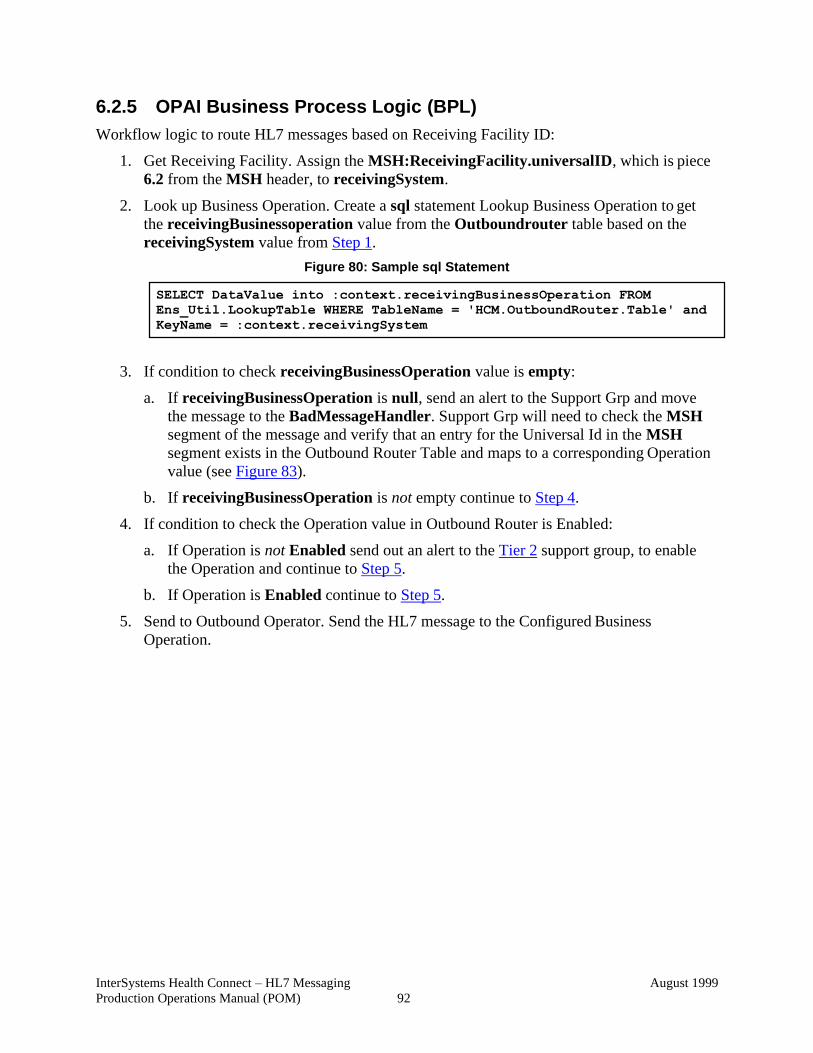
InterSystems Health Connect – HL7 Messaging
Production Operations Manual (POM)
August 1999
92
6.2.5 OPAI Business Process Logic (BPL)
Workflow logic to route HL7 messages based on Receiving Facility ID:
1. Get Receiving Facility. Assign the MSH:ReceivingFacility.universalID, which is piece
6.2 from the MSH header, to receivingSystem.
2. Look up Business Operation. Create a sql statement Lookup Business Operation to get
the receivingBusinessoperation value from the Outboundrouter table based on the
receivingSystem value from Step 1.
Figure 80: Sample sql Statement
3. If condition to check receivingBusinessOperation value is empty:
a. If receivingBusinessOperation is null, send an alert to the Support Grp and move
the message to the BadMessageHandler. Support Grp will need to check the MSH
segment of the message and verify that an entry for the Universal Id in the MSH
segment exists in the Outbound Router Table and maps to a corresponding Operation
value (see Figure 83).
b. If receivingBusinessOperation is not empty continue to Step 4.
4. If condition to check the Operation value in Outbound Router is Enabled:
a. If Operation is not Enabled send out an alert to the Tier 2 support group, to enable
the Operation and continue to Step 5.
b. If Operation is Enabled continue to Step 5.
5. Send to Outbound Operator. Send the HL7 message to the Configured Business
Operation.
SELECT DataValue into :context.receivingBusinessOperation FROM
Ens_Util.LookupTable WHERE TableName = 'HCM.OutboundRouter.Table' and
KeyName = :context.receivingSystem

InterSystems Health Connect – HL7 Messaging
Production Operations Manual (POM)
August 1999
93
REDACTED Figure 81: Business Process Logic (BPL) for OutRouter
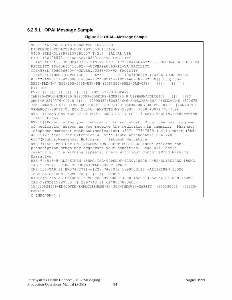
InterSystems Health Connect – HL7 Messaging
Production Operations Manual (POM)
August 1999
94
6.2.5.1 OPAI Message Sample
Figure 82: OPAI—Message Sample
MSH|~^\&|PSO VISTA|REDACTED ~DNS|PSO
DISPENSE|~REDACTED~DNS|19990530113424-
0400||RDS~O13|999157291007|T|2.4|||AL|AL|USA
PID|||101085731~~~USSSA&&0363~SS~VA FACILITY
ID&456&L^""~~~USDOD&&0363~TIN~VA FACILITY ID&456&L^""~~~USDOD&&0363~FIN~VA
FACILITY ID&456&L^16392~~~USVHA&&0363~PI~VA FACILITY
ID&456&L^508056640~~~USVBA&&0363~PN~VA FACILITY
ID&456&L||NAME~EMPLOYEE~~~~~L^""~~~~~~N||19671008|M|||4596 IRON HORSE
RD~""~ANYCITY~WY~00001~USA~P~""~021^~~ANYPLACE~NE~~""~N||(555)555-
5555~PRN~PH^(555)555-5555~WPN~PH^(555)555-5555~ORN~CP||||||||||||||||||
PV1||O|
PV2||||||||||||||||||||||||OPT SC~NO COPAY|
IAM||D~DRUG~LGMR120.8|20009~CODEINE~LGMR120.8|U|PHARMACOLOGIC||||||||||||C
ORC|NW|2210376~OP7.0|||||||19990430|520824646~EMPLOYEE~EMPLOYEENAME~E||520675
728~REDACTED|RX1||19990430|REFILL|325~CHY EMERGENCY ROOM~99PSC||||ANYSITE
VAM&ROC~~999|P.O. BOX 20350~~ANYSITE~WY~99999- 7008|(307)778-7524
NTE|1||TAKE ONE TABLET BY MOUTH ONCE DAILY FOR 15 DAYS TESTING|Medication
Instructions
NTE|2||Do not allow your medication to run short. Order the next shipment
of medication assoon as you receive the medication in themail. Pharmacy
Telephone Numbers: EMERGENCYMedication: (307) 778-7555 (Call Center):888-
483-9127 **Ask for Extension 4205*** (Auto-Attendant): 866-420-
6337(Nights,Weekends, Holidays) |Patient Narrative
NTE|3||SEE MEDICATION INFORMATION SHEET FOR DRUG INFO\.sp\Some non-
prescription drugs may aggravate your condition. Read all labels
carefully. If a warning appears, check with your doctor.|Drug Warning
Narrative
RXE|""|A1345~ALISKIREN 150MG TAB~99PSNDF~4230.18208.4452~ALISKIREN 150MG
TAB~99PSD|||20~MG~99PSU|63~TAB~99PSF||WALK-
IN||15|~TAB|11|BM3747271|~~|2297748|9|2|19990521|||~ALISKIREN 150MG
TAB^~ALISKIREN 150MG TAB||||||||||N^0^N
RXD|2|A1345~ALISKIREN 150MG TAB~99PSNDF~4230.18208.4452~ALISKIREN 150MG
TAB~99PSD|19990530||||2297748|11|6P^00078-0485-
15|520824646~EMPLOYEE~EMPLOYEENAME~E||30|WINDOW||~SAFETY||||20190501||||||33~
PATIEN
T INFO^9N~^||
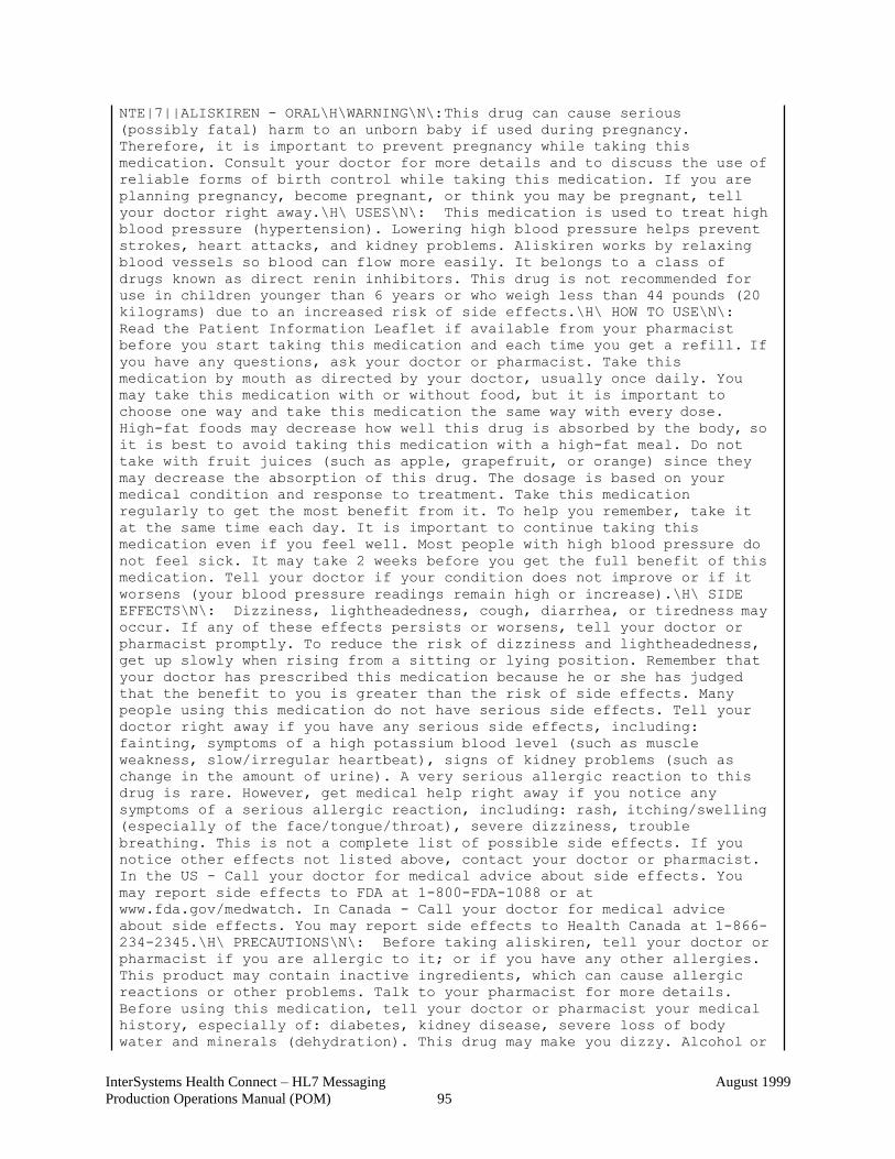
InterSystems Health Connect – HL7 Messaging
Production Operations Manual (POM)
August 1999
95
NTE|7||ALISKIREN - ORAL\H\WARNING\N\: This drug can cause serious
(possibly fatal) harm to an unborn baby if used during pregnancy.
Therefore, it is important to prevent pregnancy while taking this
medication. Consult your doctor for more details and to discuss the use of
reliable forms of birth control while taking this medication. If you are
planning pregnancy, become pregnant, or think you may be pregnant, tell
your doctor right away.\H\ USES\N\: This medication is used to treat high
blood pressure (hypertension). Lowering high blood pressure helps prevent
strokes, heart attacks, and kidney problems. Aliskiren works by relaxing
blood vessels so blood can flow more easily. It belongs to a class of
drugs known as direct renin inhibitors. This drug is not recommended for
use in children younger than 6 years or who weigh less than 44 pounds (20
kilograms) due to an increased risk of side effects.\H\ HOW TO USE\N\:
Read the Patient Information Leaflet if available from your pharmacist
before you start taking this medication and each time you get a refill. If
you have any questions, ask your doctor or pharmacist. Take this
medication by mouth as directed by your doctor, usually once daily. You
may take this medication with or without food, but it is important to
choose one way and take this medication the same way with every dose.
High-fat foods may decrease how well this drug is absorbed by the body, so
it is best to avoid taking this medication with a high-fat meal. Do not
take with fruit juices (such as apple, grapefruit, or orange) since they
may decrease the absorption of this drug. The dosage is based on your
medical condition and response to treatment. Take this medication
regularly to get the most benefit from it. To help you remember, take it
at the same time each day. It is important to continue taking this
medication even if you feel well. Most people with high blood pressure do
not feel sick. It may take 2 weeks before you get the full benefit of this
medication. Tell your doctor if your condition does not improve or if it
worsens (your blood pressure readings remain high or increase).\H\ SIDE
EFFECTS\N\: Dizziness, lightheadedness, cough, diarrhea, or tiredness may
occur. If any of these effects persists or worsens, tell your doctor or
pharmacist promptly. To reduce the risk of dizziness and lightheadedness,
get up slowly when rising from a sitting or lying position. Remember that
your doctor has prescribed this medication because he or she has judged
that the benefit to you is greater than the risk of side effects. Many
people using this medication do not have serious side effects. Tell your
doctor right away if you have any serious side effects, including:
fainting, symptoms of a high potassium blood level (such as muscle
weakness, slow/irregular heartbeat), signs of kidney problems (such as
change in the amount of urine). A very serious allergic reaction to this
drug is rare. However, get medical help right away if you notice any
symptoms of a serious allergic reaction, including: rash, itching/swelling
(especially of the face/tongue/throat), severe dizziness, trouble
breathing. This is not a complete list of possible side effects. If you
notice other effects not listed above, contact your doctor or pharmacist.
In the US - Call your doctor for medical advice about side effects. You
may report side effects to FDA at 1-800-FDA-1088 or at
www.fda.gov/medwatch. In Canada - Call your doctor for medical advice
about side effects. You may report side effects to Health Canada at 1-866-
234-2345.\H\ PRECAUTIONS\N\: Before taking aliskiren, tell your doctor or
pharmacist if you are allergic to it; or if you have any other allergies.
This product may contain inactive ingredients, which can cause allergic
reactions or other problems. Talk to your pharmacist for more details.
Before using this medication, tell your doctor or pharmacist your medical
history, especially of: diabetes, kidney disease, severe loss of body
water and minerals (dehydration). This drug may make you dizzy. Alcohol or
InterSystems Health Connect – HL7 Messaging
Production Operations Manual (POM)
August 1999
96
marijuana can make you more dizzy. Do not drive, use machinery, or do
anything that needs alertness until you can do it safely. Limit alcoholic
beverages. Talk to your doctor if you are using marijuana. Too much
sweating, diarrhea, or vomiting may cause you to feel lightheaded. Report
prolonged diarrhea or vomiting to your doctor. This medication may
increase your potassium levels. Before using potassium supplements or salt
substitutes that contain potassium, consult your doctor or pharmacist.
Before having surgery, tell your doctor or dentist about all the products
you use (including prescription drugs, nonprescription drugs, and herbal
products). This medication is not recommended for use during pregnancy. It
may harm an unborn baby. Consult your doctor for more details. (See also
Warning section.) It is unknown if this drug passes into breast milk.
Consult your doctor before breast-feeding.\H\ DRUG INTERACTIONS\N\: See
also How to Use and Precautions sections. Drug interactions may change how
your medications work or increase your risk for serious side effects. This
document does not contain all possible drug interactions. Keep a list of
all the products you use (including prescription/nonprescription drugs and
herbal products) and share it with your doctor and pharmacist. Do not
start, stop, or change the dosage of any medicines without your doctor's
approval. Some products that may interact with this drug include: drugs
that may increase the level of potassium in the blood (including ACE
inhibitors such as benazepril/lisinopril, ARBs such as
candesartan/losartan, birth control pills containing drospirenone). Other
medications can affect the removal of aliskiren from your body, which may
affect how aliskiren works. Examples include itraconazole, cyclosporine,
quinidine, among others. Some products have ingredients that could raise
your blood pressure. Tell your pharmacist what products you are using, and
ask how to use them safely (especially cough-and-cold products, diet aids,
or NSAIDs such as ibuprofen/naproxen).\H\ OVERDOSE\N\: If someone has
overdosed and has serious symptoms such as passing out or trouble
breathing, call 911. Otherwise, call a poison control center right away.
US residents can call their local poison control center at 1-800-222-1222.
Canada residents can call a provincial poison control center. Symptoms of
overdose may include: severe dizziness, fainting.\H\ NOTES\N\: Do not
share this medication with others. Lifestyle changes that may help this
medication work better include exercising, stopping smoking, and eating a
low-cholesterol/low-fat diet. Consult your doctor for more details.
Laboratory and/or medical tests (such as kidney function, potassium
levels) should be performed regularly to monitor your progress or check
for side effects. Have your blood pressure checked regularly while taking
this medication. Learn how to monitor your own blood pressure at home, and
share the results with your doctor.\H\ MISSED DOSE\N\: If you miss a
dose, take it as soon as you remember. If it is near the time of the next
dose, skip the missed dose and resume your usual dosing schedule. Do not
double the dose to catch up.|Patient Medication Instructions
NTE|9||The VA Notice of Privacy Practices, IB 10-163, which outlines your
privacy rights, is available online at http://www1.va.gov/Health/ or you
may obtain a copy by writing the VHA Privacy Office (19F2),810 Vermont
Avenue NW, Washington, DC 20420.|Privacy Notification
RXR|1~ORAL (BY MOUTH)~99PSR||||
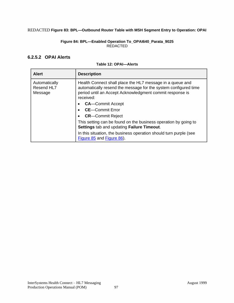
InterSystems Health Connect – HL7 Messaging
Production Operations Manual (POM)
August 1999
97
REDACTED Figure 83: BPL—Outbound Router Table with MSH Segment Entry to Operation: OPAI
Figure 84: BPL—Enabled Operation To_OPAI640_Parata_9025
REDACTED
6.2.5.2 OPAI Alerts
Table 12: OPAI—Alerts
Alert Description
Automatically
Resend HL7
Message
Health Connect shall place the HL7 message in a queue and
automatically resend the message for the system configured time
period until an Accept Acknowledgment commit response is
received:
• CA—Commit Accept
• CE—Commit Error
• CR—Commit Reject
This setting can be found on the business operation by going to
Settings tab and updating Failure Timeout.
In this situation, the business operation should turn purple (see Figure 85 and Figure 86).
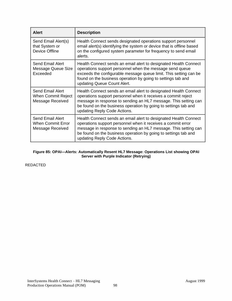
InterSystems Health Connect – HL7 Messaging
Production Operations Manual (POM)
August 1999
98
Alert Description
Send Email Alert(s)
that System or
Device Offline
Health Connect sends designated operations support personnel
email alert(s) identifying the system or device that is offline based
on the configured system parameter for frequency to send email
alerts.
Send Email Alert
Message Queue Size
Exceeded
Health Connect sends an email alert to designated Health Connect
operations support personnel when the message send queue
exceeds the configurable message queue limit. This setting can be
found on the business operation by going to settings tab and
updating Queue Count Alert.
Send Email Alert
When Commit Reject
Message Received
Health Connect sends an email alert to designated Health Connect
operations support personnel when it receives a commit reject
message in response to sending an HL7 message. This setting can
be found on the business operation by going to settings tab and
updating Reply Code Actions.
Send Email Alert
When Commit Error
Message Received
Health Connect sends an email alert to designated Health Connect
operations support personnel when it receives a commit error
message in response to sending an HL7 message. This setting can
be found on the business operation by going to settings tab and
updating Reply Code Actions.
Figure 85: OPAI—Alerts: Automatically Resent HL7 Message: Operations List showing OPAI Server with Purple Indicator (Retrying)
REDACTED

InterSystems Health Connect – HL7 Messaging
Production Operations Manual (POM)
August 1999
99
Figure 86: HL7 Health Connect—Production Configuration Legend: Status Indicators
InterSystems Health Connect – HL7 Messaging
Production Operations Manual (POM)
August 1999
100
6.1.7 OPAI Approval Signatures
The signatures in this section indicate the approval of the HL7 InterSystems Health Connect
Production Operations Manual (POM) and accompanying RACI for the Outpatient Pharmacy
Automation Interface (OPAI) application.
NOTE: Digital signatures will only be added to the PDF version of the Microsoft® Word
document (i.e., HC-HL7_Messaging_1_0_POM-Signed.pdf).
REDACTED
REDACTED
REDACTED
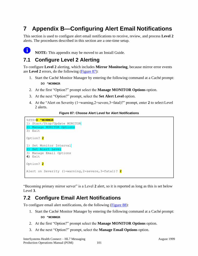
InterSystems Health Connect – HL7 Messaging
Production Operations Manual (POM)
August 1999
101
7 Appendix B—Configuring Alert Email Notifications This section is used to configure alert email notifications to receive, review, and process Level 2
alerts. The procedures described in this section are a one-time setup.
NOTE: This appendix may be moved to an Install Guide.
7.1 Configure Level 2 Alerting
To configure Level 2 alerting, which includes Mirror Monitoring, because mirror error events
are Level 2 errors, do the following (Figure 87):
1. Start the Caché Monitor Manager by entering the following command at a Caché prompt:
DO ^MONMGR
2. At the first “Option?” prompt select the Manage MONITOR Options option.
3. At the next “Option?” prompt, select the Set Alert Level option.
4. At the “Alert on Severity (1=warning,2=severe,3=fatal)?” prompt, enter 2 to select Level
2 alerts.
Figure 87: Choose Alert Level for Alert Notifications
“Becoming primary mirror server” is a Level 2 alert, so it is reported as long as this is set below
Level 3.
7.2 Configure Email Alert Notifications
To configure email alert notifications, do the following (Figure 88):
1. Start the Caché Monitor Manager by entering the following command at a Caché prompt:
DO ^MONMGR
2. At the first “Option?” prompt select the Manage MONITOR Options option.
3. At the next “Option?” prompt, select the Manage Email Options option.
%SYS>D ^MONMGR
1) Start/Stop/Update MONITOR
2) Manage MONITOR Options
3) Exit
Option? 2
1) Set Monitor Interval
2) Set Alert Level
3) Manage Email Options
4) Exit
Option? 2
Alert on Severity (1=warning,2=severe,3=fatal)? 2
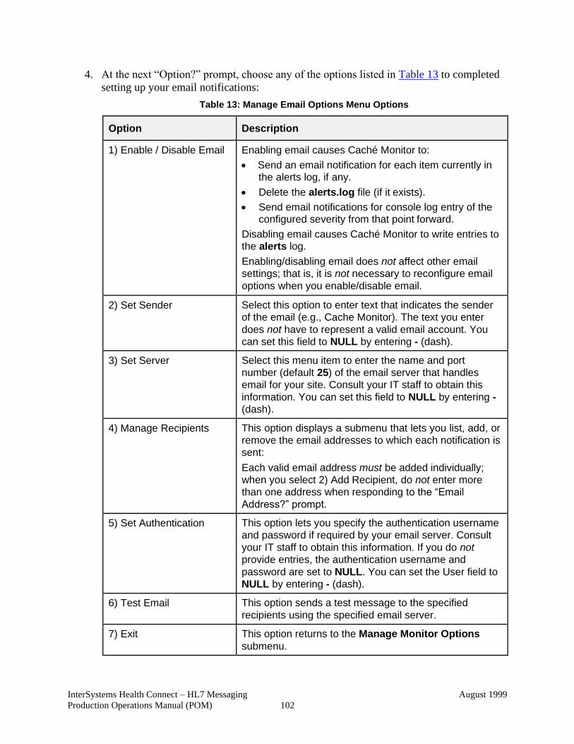
InterSystems Health Connect – HL7 Messaging
Production Operations Manual (POM)
August 1999
102
4. At the next “Option?” prompt, choose any of the options listed in Table 13 to completed
setting up your email notifications:
Table 13: Manage Email Options Menu Options
Option Description
1) Enable / Disable Email Enabling email causes Caché Monitor to:
• Send an email notification for each item currently in the alerts log, if any.
• Delete the alerts.log file (if it exists).
• Send email notifications for console log entry of the configured severity from that point forward.
Disabling email causes Caché Monitor to write entries to the alerts log.
Enabling/disabling email does not affect other email
settings; that is, it is not necessary to reconfigure email
options when you enable/disable email.
2) Set Sender Select this option to enter text that indicates the sender
of the email (e.g., Cache Monitor). The text you enter
does not have to represent a valid email account. You
can set this field to NULL by entering - (dash).
3) Set Server Select this menu item to enter the name and port
number (default 25) of the email server that handles
email for your site. Consult your IT staff to obtain this
information. You can set this field to NULL by entering -
(dash).
4) Manage Recipients This option displays a submenu that lets you list, add, or
remove the email addresses to which each notification is
sent:
Each valid email address must be added individually;
when you select 2) Add Recipient, do not enter more
than one address when responding to the “Email
Address?” prompt.
5) Set Authentication This option lets you specify the authentication username
and password if required by your email server. Consult
your IT staff to obtain this information. If you do not
provide entries, the authentication username and
password are set to NULL. You can set the User field to
NULL by entering - (dash).
6) Test Email This option sends a test message to the specified
recipients using the specified email server.
7) Exit This option returns to the Manage Monitor Options
submenu.
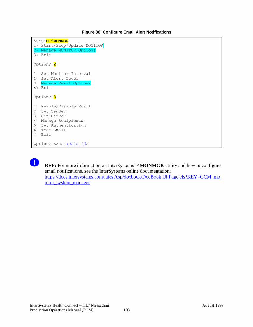
InterSystems Health Connect – HL7 Messaging
Production Operations Manual (POM)
August 1999
103
Figure 88: Configure Email Alert Notifications
REF: For more information on InterSystems’ ^MONMGR utility and how to configure
email notifications, see the InterSystems online documentation:
https://docs.intersystems.com/latest/csp/docbook/DocBook.UI.Page.cls?KEY=GCM_mo
nitor_system_manager
%SYS>D ^MONMGR
1) Start/Stop/Update MONITOR
2) Manage MONITOR Options
3) Exit
Option? 2
1) Set Monitor Interval
2) Set Alert Level 3) Manage Email Options 4) Exit
Option? 3
1) Enable/Disable Email
2) Set Sender 3) Set Server 4) Manage Recipients 5) Set Authentication 6) Test Email 7) Exit
Option? <See Table 13>
Related Documents