Note on Hitomi attitude accuracy Doc no: Hitomi-MEMO-2016-001 Issue: 3.0 Hitomi Date: December 7, 2016 Page: 1 of 15 Title: Note on Hitomi attitude accuracy Prepared by: Ryo Iizuka Shinya Nakashima Yoshitomo Maeda Yoh Takei ISAS/JAXA ISAS/JAXA ISAS/JAXA ISAS/JAXA Date: December 7, 2016 Checked by: Manabu Ishida Date: December 7, 2016 Agreed by: Date: Authorized by: Manabu Ishida Date: December 7, 2016 Document change record Issue Date Changed section Description of change 3.0 2016-12-07 Appendix E, etc Reflected the change in the final (3rd) pipeline release (Dec 2016) 2.1 2016-09-20 — Small correction 2.0 2016-09-18 Appendix D, etc Reflected the change in 2nd pipeline release (Sep 2016) 1.1 2016-08-29 — Small correction 1.0 2016-08-24 — Official release

Welcome message from author
This document is posted to help you gain knowledge. Please leave a comment to let me know what you think about it! Share it to your friends and learn new things together.
Transcript
Note on Hitomiattitude accuracy
Doc no: Hitomi-MEMO-2016-001Issue: 3.0
Hitomi Date: December 7, 2016Page: 1 of 15
Title: Note on Hitomi attitude accuracy
Prepared by: Ryo IizukaShinya NakashimaYoshitomo MaedaYoh Takei
ISAS/JAXAISAS/JAXAISAS/JAXAISAS/JAXA
Date: December 7, 2016
Checked by: Manabu Ishida Date: December 7, 2016Agreed by: Date:
Authorized by: Manabu Ishida Date: December 7, 2016
Document change record
Issue Date Changed section Description of change3.0 2016-12-07 Appendix E, etc Reflected the change in the final (3rd) pipeline release (Dec 2016)2.1 2016-09-20 — Small correction2.0 2016-09-18 Appendix D, etc Reflected the change in 2nd pipeline release (Sep 2016)1.1 2016-08-29 — Small correction1.0 2016-08-24 — Official release
Note on Hitomiattitude accuracy
Doc no: Hitomi-MEMO-2016-001Issue: 3.0
Hitomi Date: December 7, 2016Page: 2 of 15
Contents
References 2
1 Introduction 3
2 Summary of attitude accuracy 3
3 Recipe to pick-up STT available duration 43.1 How to pick up duration STT is available for attitude determination . . . . . . . . . . . . . . . . 63.2 How to pick up duration STT is used for attitude control . . . . . . . . . . . . . . . . . . . . . . 6
A ASTRO-H attitude system 7A.1 STT available and non-available observations . . . . . . . . . . . . . . . . . . . . . . . . . . . . . 7A.2 On-ground pointing correction . . . . . . . . . . . . . . . . . . . . . . . . . . . . . . . . . . . . . 7A.3 Comments on aberration corrections . . . . . . . . . . . . . . . . . . . . . . . . . . . . . . . . . . 8
B X-ray image analysis 9
C SXS field of view and observed targets 11
D Updates in the 2nd pipeline (Sep 2016) 13
E Updates in the 3rd pipeline (Dec 2016) 13
References
[1] ASTH-199-04 ASTRO-H指向管理条件書 (ASTRO-H Alignment control requirement) Version 2, 2010-10-26,NEC
[2] ASTH-NT-D16025 ASTRO-H 「ひとみ」衛星地上姿勢決定作業作業報告書, 2016-06-10 NEC
[3] Plot of Hitomi Attitude Accuracy (STT ON/OFF) (attachment of this document), version 5.3, 2016-12-06
[4] ASTH-NT-D16098 ASTRO-H 「ひとみ」衛星地上姿勢決定作業作業その 2 報告書, 2016-11-21 NEC

Note on Hitomiattitude accuracy
Doc no: Hitomi-MEMO-2016-001Issue: 3.0
Hitomi Date: December 7, 2016Page: 3 of 15
1 Introduction
The requirement of ASTRO-H attitude control (on pointing direction) is summarized in Table. 1 [1]. Note thatthe requirement is defined while the STT is available to control the attitude. There is no specific requirementwhen the STT is not available (e.g, during Earth occultation of STT FoV). In addition, this requirement shouldbe applicable for observations after the commissioning of AOCS (attitude and orbit control system) subsystemis finished. The spacecraft is not designed to aim at very high accuracy like Chandra or XMM.
Table 1: Requirement for Hitomi attitude control on pointing direction
Absolute accuracy of image center Attitude stability (variation in time)
Control accuracy SXS: 1.5 mm or 55′′ (3σ) from detector center SXS: N/A(onboard) SXI: 5.0 mm or 184′′ (3σ) from detector center SXI: 10′′ (3σ) in 4 s
HXI: 3.0 mm or 51′′ (3σ) from detector center HXI: N/A
Determination accuracy SXS: 20′′ (3σ) SXS: 20′′ (3σ) in one observation(offline) SXI: 20′′ (3σ) SXI: 20′′ (3σ) in one observation
HXI: 20′′ (3σ) HXI: 20′′ (3σ) in one observation
Since the observation of Hitomi was terminated before AOCS commissioning was finished, it is highlydesirable to obtain the attitude accuracy for available observations with the similar accuracy to that expectedafter AOCS commissioning was finished. Moreover, from science point of view, the data when STT was notavailable for attitude control are equally precious, and hence the better attitude accuracy during these periodsis also desirable.
As of 1st pipeline release (released in June/July), the attitude accuracy is limited, in not only actual control(wobbling of actual spacecraft attitude) but also attitude determination accuracy (error in the pointing directionstored in the pipeline product compared to the actual pointing direction). It is partly because the AOCS wasstill under start-up and check-out, and partly because the attitude stored in the pipeline product was based onthe first “trial” and hence correlation study with X-ray image was not performed.
In this document, the current attitude accuracy is summarized, along with related information. The dataused in the analysis shown in this document are from 1st release, distributed from 2016-06-25 to 2016-08-01.The summary of the updates in the 2nd release (Sep 2016) and resultant accuracy/stability of the reconstructedattitude are shown in Appendix D. The summary of the updates in the 3rd (final) release (Dec 2016) andresultant accuracy/stability of the reconstructed attitude are shown in Appendix E. In Appendix E, the attitudeaccuracy and stability for each instrument are also shown when available, so that the difference among theinstrument is seen.
2 Summary of attitude accuracy
Accuracy and stability of the attitude for each observation are evaluated using the distribution of observedX-ray photons from the analysis described in Appendix. B. The results in SKY coordinates (RA and Dec) aresummarized in Table 21. The accuracy value is the angular distance between the target coordinates (determinedby SIMBAD database) and the center of the X-ray photon distribution. The stability value is the standarddeviation of the distribution of the X-ray image center taken from short intervals (60 s or 300 s). Note that thevalue of stability is affected by the error (uncertainty) in determining the center of X-ray distribution. Sincethe photon statistics of IGR J16318-4848 and RXJ 1856.5-3754 observations is low, the stability values of theseobservations are likely affected (degraded) by the error of X-ray image center location.
During Hitomi observations, STT is sometimes available and used for onboard attitude control, but some-times not. Actually the following three cases appear in all observations.
1The values of Table 2 is revised for Issue 2.0 from Issue 1.1.

Note on Hitomiattitude accuracy
Doc no: Hitomi-MEMO-2016-001Issue: 3.0
Hitomi Date: December 7, 2016Page: 4 of 15
Table 2: Accuracy and stability of attitude for the SCT 1st release data (distributed on Jun 25 – Aug 1)
STT controlled STT available STT unavailable
Target OBSID Instrument§ Acc.* Stb.† Acc.* Stb.† Acc.* Stb.†
Perseus core‡ 100040010 SXS - - - - - -
Perseus core adjustment 100040020 SXS 12.6 4.9 9.3 6.1 14.4 8.8
Perseus 100040030 SXS 11.6 5.6 8.5 7.7 20.3 7.6
” 100040040 SXS 12.3 6.1 8.8 9.7 21.5 8.8
” 100040050 SXS 19.4 7.1 12.0 8.6 11.5 8.7
Perseus adjustment 100040060 SXS 24.9 5.3 24.8 7.0 31.4 8.1
N132D 100041010 SXI 23.4 2.0 23.8 23.8 N/A N/A
” 100041020 SXI 22.1 7.7 21.8 7.8 20.8 7.4
IGR J16318-4848 100042040 SXI 7.9 7.3 7.7 8.0 15.2 8.6
RXJ1856.5-3754 100043010–40 SXI 35.4 8.0 40.0 7.4 11.8 6.6
G21.5-0.9 100050010 SXS 8.9 4.9 9.5 5.9 10.7 10.2
” 100050020 SXS 9.0 4.9 10.1 6.3 14.9 11.0
” 100050030 SXS 9.1 4.8 9.3 4.9 17.0 12.3
” 100050040 SXS 8.9 5.0 9.4 5.9 13.5 8.7
” 100050050 SXS 6.7 2.5 10.2 6.1 N/A N/A
RXJ1856.5-3754 100043050 SXI 18.4 9.2 18.6 9.3 17.1 7.0
” 100043060 SXI 18.8 9.3 19.2 8.8 21.1 6.1
Crab 100044010 SXS 4.4 3.1 4.4 3.3 20.6 6.5
NOTE: values for the 2nd and 3rd release data are shown in Table 4 and 5, respectively.§ Instrument used for the analysis.* Accuracy of image center in the unit of arcsecond.† Stability of attitude (1σ) in the unit of arcsecond.‡ Cannot evaluate attitude because the center of Perseus is not in the SXS FOV.
1. One of STTs is used for onboard attitude control. The attitude control accuracy is good and attitudedetermination accuracy is good.
2. (One or two of) STT is available for offline attitude determination, but not used for onboard attitudecontrol. The attitude control accuracy is not good and attitude determination accuracy is good.
3. None of STT is available for attitude determination (e.g., Earth occultation of two STT FoVs) nor attitudecontrol. The attitude control accuracy is not good and attitude determination accuracy is not good.
The Table 2 shows accuracy and stability for these three cases separately. The accuracy and stability of“STT unavailable” is significantly worse than the other two in most observations. While the stability of “STTavailable” should be worse than “STT controlled” in DET coordinates, the values in SKY coordinates are similaras shown in the Table. Note that Table 2 is for the data of 1st pipeline release. The information for the 2ndand 3rd pipeline release are shown in Table 4 and 5, respectively.
3 Recipe to pick-up STT available duration
Since the attitude determination or control accuracy depends on STT availability, one may want to pick upX-ray photons only while the STT is available (either determination or control), in order to obtain X-ray datafor better attitude accuracy, with sacrifice of photon statistics (X-rays for other durations will be discarded).In such a science case that the attitude accuracy is more important than photon statistics, a user may extractX-ray events while the STT is available by HK parameters as shown in Table 3, from ah${SEQ NO}gen a0.hk
file. Note that the cleaned events in the pipeline contain all the data shown in the three rows of Table 3, i.e.,

Note on Hitomiattitude accuracy
Doc no: Hitomi-MEMO-2016-001Issue: 3.0
Hitomi Date: December 7, 2016Page: 5 of 15
all of “STT is not used for attitude determination nor control”, “STT is used for attitude determination”, and“STT is used for attitude control”. If a user does not need additional attitude accuracy, the data selectionshown in this section is not recommended because the selection leads to smaller statistics.
Table 3: Parameters to pick up X-ray photons while the STT is available.)393:3?=B <4 06�������53;/0��68
�A?3;>7<; -� /��%�/%�/��)�/��,/�. �A?3;>7<; -� /��%�/� /#$".�A?3;>7<;-� /��%�/�$�(/� /#"/���� $*)/��,/�.
()) 7> ;<? @>32 4<= 0??7?@2323?3=:7;0?7<; ;<= 0??7?@23 1<;?=<9
��%�/())�/&/+�!����� ����%�/())�/&/+�!����� #�� #��
()) 7> @>32 4<= 0??7?@23 23?3=:7;0?7<;��%�/())�/&/+�!����� CC��%�/())�/&/+�!����� #�� #��
()) 7> @>2 4<= 0??7?@23 1<;?=<9 ��%�/())��������/&/+�!�����
��%�/�$#)/"$����� ����%�/�$#)/(*�/"$����� ����%�/())��������/�#)�/()(��� ����%�/���'/�$"%/())��������/��/�''/�!����
��%�/��(/())/()(��� ����%�/��(/ �/*%���
�������� 7> ��%�/��(/())/(�! 7; �A?3;>7<; -� /��%�/�$�(/� /#"/���� $*)/��,/�.
�L��G�IEFM��HN�#�� K���IJ�GED
Examples of a script to pick up X-ray photons while the STT is used for attitude determination or attitudecontrol are as follows.

Note on Hitomiattitude accuracy
Doc no: Hitomi-MEMO-2016-001Issue: 3.0
Hitomi Date: December 7, 2016Page: 6 of 15
3.1 How to pick up duration STT is available for attitude determination
#!/bin/bash
seq_num=100044010
gen_hk_file=./ah${seq_num}gen_a0.hk
gti_out_file=gti_stt_determination.fits
ahgtigen "infile=${gen_hk_file}[HK_ACPA_PD_DATA_4HZ_1]" "outfile=${gti_out_file}" \
’gtifile=none’ "gtiexpr=(ACPA_STT1_Q_VALID==1)||(ACPA_STT2_Q_VALID==1)" \
’mergegti=and’ ’leapsecfile=none’ ’instrume=sxs’ ’chatter=2’ \
’clobber=yes’ ’logfile=test.log’
3.2 How to pick up duration STT is used for attitude control
#!/bin/bash
seq_num=100044010
gen_hk_file=./ah${seq_num}gen_a0.hk
stt_sel=2
gti_out_file=gti_stt_control.fits
### Remove TNULL rows from each extension ###
ftcopy "infile=${gen_hk_file}[HK_ACPA_HK_NOM][col *][ACPA_CONT_MODE<255]" \
’clobber=yes’ ’copyall=no’ ’outfile=hk_1.fits.tmp’
ftcopy "infile=${gen_hk_file}[HK_ACPA_AOCS_HK_NM_CHECKOUT_1HZ_1][col *][ACPA_ADS_STT_STS<255]" \
’clobber=yes’ ’copyall=no’ ’outfile=hk_2.fits.tmp’
### Create GTI for each extension ###
ahgtigen "infile=hk_1.fits.tmp[HK_ACPA_HK_NOM]" ’outfile=gti_stt_1.fits.tmp’ ’gtifile=none’ \
"gtiexpr=(ACPA_CONT_MODE==6)&&(ACPA_CONT_SUB_MODE==2)&&(ACPA_STT${stt_sel}_INTF_STS==0) \
&&(ACPA_FDIR_COMP_STT${stt_sel}_ID_ERR_FLG==0)" ’mergegti=and’ ’leapsecfile=none’ \
’instrume=sxs’ ’chatter=2’ ’clobber=yes’ ’logfile=test.log’
ahgtigen "infile=hk_2.fits.tmp[HK_ACPA_AOCS_HK_NM_CHECKOUT_1HZ_1]" \
’outfile=gti_stt_2.fits.tmp’ ’gtifile=none’ \
’gtiexpr=(ACPA_ADS_STT_STS==1)&&(ACPA_ADS_KF_UP==1)’ ’mergegti=and’ ’leapsecfile=none’ \
’instrume=sxs’ ’chatter=2’ ’clobber=yes’ ’logfile=test.log’
ahgtigen "infile=${gen_hk_file}[HK_ACPA_PD_DATA_4HZ_1]" ’outfile=gti_stt_3.fits.tmp’ \
’gtifile=none’ "gtiexpr=(ACPA_STT${stt_sel}_Q_VALID==1)" ’mergegti=and’ \
’leapsecfile=none’ ’instrume=sxs’ ’chatter=2’ ’clobber=yes’ ’logfile=test.log’
### Merge GTI file created from each extension ###
## First create a list
cat <<EOF > gti_stt.lst.tmp
gti_stt_1.fits.tmp
gti_stt_2.fits.tmp
gti_stt_3.fits.tmp
EOF
## Then, merge
ahgtigen ’infile=NONE’ "outfile=${gti_out_file}" ’gtifile=@gti_stt.lst.tmp’ \
’gtiexpr=NONE’ ’mergegti=AND’ ’clobber=yes’ ’chatter=2’
### Remove intermediate files ###
rm -f hk_[12].fits.tmp gti_stt_[123].fits.tmp gti_stt.lst.tmp

Note on Hitomiattitude accuracy
Doc no: Hitomi-MEMO-2016-001Issue: 3.0
Hitomi Date: December 7, 2016Page: 7 of 15
A ASTRO-H attitude system
ASTRO-H is in many aspects similar to Suzaku in terms of attitude controlling. The spacecraft attitude isstabilized by four sets of reaction wheels, while the attitude is measured by three gyroscopes (IRUs) and twostar trackers (STTs) (see Fig. 1 for locations). The accumulated angular momentum is removed by magnetictorquers that interact with the Earth’s magnetic field.
Since the satellite revolves in a near-earth orbit, most targets are occulted by the Earth for about one thirdof each orbit, but some objects near the orbital poles can be observed nearly continuously. Observation is alsointerrupted by passages of the South Atlantic Anomaly. The similar interrupt is also made for the STTs, too.
The field of view of the STTs is close to the X-ray telescopes and hence it covers that of the X-ray instruments(SXS,SXI,HXI and SGD; see Figure 2). The STTs are designed to track the stars as long as possible when theX-ray telescopes watch celestial objects (visible) (it is improvement from Suzaku). However, since the field ofview of STTs is much larger than that of the X-ray instruments, the allocation of the “cone” angles for theearth’s occultation and earth’s stray light for the STTs is also much larger than the field of view of the X-rayinstruments, as large as 20 degrees. Therefore, STT is not available for all periods when celestial objects arevisible by X-ray telescopes.
The duration that the STTs track the stars gives a good pointing accuracy (see § 2), while the durationwhen the STTs do not track the stars is expected to show worse pointing accuracy. The field of view of theSTTs are tilted by 5 degrees from the satellite Z-axis. The tilt direction of the STTs’ axes are not the sameeach other. The duration of the earth occultation of the STT1 and STT2 are then not the same, too.
A.1 STT available and non-available observations
Fig. 2 demonstrate schematics of the STT available or non-available observations. For more than the half ofthe X-ray visibility, the attitude is controlled by the STTs (the case (a) in Fig. 2 ). Since the STTs attitudeaccuracy is as good as arcsecs in order, the pointing accuracy of the X-ray system is also good in the same order(see Table 2). However, since the cone angle of the STTs are larger than those of the X-ray instruments, thelow-earth-elevation observations are sometimes controlled without the STTs.
In most of the observations, the earth occultation occurs every orbit. The low-elevation observations is thenmade at the egress and/or the ingress of the earth occultation of the of each orbit. The STTs tracking is endednear the ingress. The AOCU tries to keep its attitude stable referring to the IRUs. Usually, the pointing isstill stable close the ingress, while the attitude error becomes larger at the egress since the attitude control wasdone by using only IRU information for a long time. The STT detects the pointing shift at the egress (whenthe STT becomes available) and the position of the X-ray source is corrected rapidly.
If the pointing is stable, there should be no shift of the target position in the detector coordinates (i.e.,the RAW, ACT, DET, FOC coordinates.). Therefore, the stability is usually confirmed in these coordinates atthe duration of the STTs-available and the ingress of the earth occultation. The pointing at the egress of theoccultation is unstable sometimes.
A.2 On-ground pointing correction
The conversion to the sky coordinates (the SKY coordinates) of the X-ray instruments are remade on groundby using a pre-pipeline attitude software. Since the observations of the ASTRO-H were made during thecommissioning phase of the AOCS system including the IRUs, bias of the gyros (so-called “drift rates”) are notyet calibrated well. We have to reconstruct the pointing direction by referring to the non-calibrated gyros whenthe STTs are not available. This situation makes increase the error of the pointing of the STT non-availabledurations.
While the STT is not available, the attitude is traced by time integration of gyros’ angular velocity readings.They, however, bear some bias which are different from observation to observation. Now we ignore the differenceof the bias, some observations have relatively large attitude error while others do not.

Note on Hitomiattitude accuracy
Doc no: Hitomi-MEMO-2016-001Issue: 3.0
Hitomi Date: December 7, 2016Page: 8 of 15
The attitude reconstruction algorithm used in the 1st pipeline data estimates the attitude “backwards” intime domain (by Kalman filter algorithm). This asymmetry in time results in non-uniform attitude error intime. Actually, the largest errors occur at the STT IN→OUT moments (ingress of the occultation), because theuncertainty when STT is unavailable is most accumulated at the moments, since the estimate is done reverse intime. Consequently, the source position in the SKY coordinates is wrongly corrected at the ingress of the earthoccultation. At the egress, the stability pointing is often improved in the SKY coordinate. This is illustrated inFigure 3 in § B. Note that this was improved in the 2nd pipeline data, by using the weighted mean of “backward”and “forward” estimate. See Appendix D for details.
STT-1 STT-2 STT-2behind of HXT-2behind of HXT-1
Z�
Y� X�
IRUsinside panels
Figure 1: Location of instruments of AOCS
A.3 Comments on aberration corrections
The ASTRO-H attitude system is designed to handle the aberration effect on orbit. At the launch, the AOCUonboard system started without the aberration correction. The parameters in the AOCU system were graduallychanged to correct the aberration and was finished about a month later. The pre-pipeline attitude softwareused in the 1st pipeline release does not fully account for each step of the parameter changes 2. The aberrationdue to the motion of the Earth was properly taken into account in the 2nd pipeline release, and the aberration
2 The pipeline software built by SCT has the function to correct the aberration of incoming X-rays, provided that the spacecraftattitude was properly determined by the attitude system and the pre-pipeline software. When AOCS onboard system does nothandle the aberration effect as designed in the nominal mode, the spacecraft attitude is incorrectly estimated, requiring additionalcorrection.

Note on Hitomiattitude accuracy
Doc no: Hitomi-MEMO-2016-001Issue: 3.0
Hitomi Date: December 7, 2016Page: 9 of 15
STT-1 STT-2 STT-2behind behind
Z�
Y� X�
IRUs
inside
FOV (SXS)
STT-2 cone
STT-1 cone
STT-1 STT-2 STT-2behind behind
Z�
Y� X�
IRUs
inside
FOV (SXS)
STT-2 cone
STT-1 cone
The earth(a) STT available obs. (b) IRU-only obs.
Figure 2: (a) An example of the STT available observation. Both of the two STTs cone and the X-ray FOV donot watch the earth rim. The attitude is primarily controlled by the star pattern in the STTs. (b) An exampleof the STT non-available observation. Both of the STTs’ cone covers the earth rim whereas the X-ray FOVsdo not. The attitude is controlled by relying the IRUs (gyros) only.
due to the satellite motion around the Earth was in addition taken into account in the 3rd pipeline release. SeeAppendix D and E.
B X-ray image analysis
The attitude accuracy shown in § 2 is determined as follows. Detailed results are shown in the attachment [3].The attitude accuracy is estimated using the distribution of observed X-ray photons. The “accuracy” of the
reconstructed attitude is determined by fitting an X-ray image from the whole exposure in SKY coordinates witha 2-dimension Lorentzian profile. On the other hand, the “stability” is determined by calculating the variationof the center position in the short intervals using median 50 percentile. The center of the photon distribution,along with the statistical error is determined for every 300 s interval (60 s interval is used for Crab, because thestatistics is high enough). The center position is taken as a median 50 percentile (by python media groupedfunction) in both DET and SKY coordinates. Since it is known that the attitude control/determination accuracyis different by STT status, the values in the three STT status shown in § 2 are determined separately.
The movement of the center position of each interval in DET coordinates indicates the attitude wobblingor attitude control accuracy, while the movement in SKY coordinates corresponds to attitude determinationaccuracy. These values are compared to the attitude file values in order to verify the accuracy of the attitudedetermination.
Note on Hitomiattitude accuracy
Doc no: Hitomi-MEMO-2016-001Issue: 3.0
Hitomi Date: December 7, 2016Page: 10 of 15
STT-ALLSAT-X [arcsec]
-SAT-Y [arcsec]
STT100044010
100044010 STT-ALL
SAT-X [arcsec]
-SAT-Y [arcsec]
STT
100050010 STT-ALL
SAT-X [arcsec]
-SAT-Y [arcsec]
STT
STT-ALL
100050010 STT-ALL
SAT-X [arcsec]
-SAT-Y [arcsec]
STT
DET
DET
SKY
SKY
G21.5-0.9 example Crab exampleDET
DET
SKY
SKYJump of pointing direction when STT became available is tracked by attitude file.
Attitude right after STT became unavailable is not correctly estimated, introducing artificial attitude error
Time TimeBlue-hatched area: STT is available for attitude control Blue-hatched area: STT is available for attitude control
Figure 3: Examples of X-ray image analysis using the 1st pipeline data distributed from 2016-06-25 to 2016-08-01: G21.5-0.9 (left) and Crab (right) observations. Red, green, blue and purple data points are X-ray imagecenter taken by SXS, SXI, HXI1 and HXI2, respectively, while the light-blue line shows the attitude data takenfrom att file. Top two panels shows the X-ray photon position taken in DET coordinates, while bottom twopanels shows the position taken in SKY coordinates. Both DET and SKY data are converted in SAT coordinatesand then plotted in SAT-X (upper) and -SAT-Y (lower) coordinates. Blue-hatched region indicates the durationwhen STT is available for attitude control. It is known that the attitude sometimes shows a “jump” when STTbecomes available for attitude control, or when STT becomes unavailable for attitude determination. Theformer corresponds to the actual attitude jump, as is visible in the example of G21.5-0.9, which is a result ofadjusting spacecraft pointing to correct attitude error accumulated when STT is unavailable, while the latter isan artifact due to incorrect attitude estimate, as is visible in the example of Crab. In the former case, attitudefluctuation in SKY coordinates is better (smaller) than in DET coordinates, while in the latter case, that inDET coordinates is better.
It is known that the attitude determined sometimes shows “jumps”. There are two patterns: one occurswhen STT becomes available for attitude control after long STT-unavailable time (egress of the occultation),while the other occurs when the STT becomes unavailable for attitude determination (ingress of the occultation).For better looking and understanding, two examples from [3] are shown in Figure 3. Left panels show data ofG21.5-0.9 observation, while the right panels Crab. Blue hatched regions are while STT is available for attitudecontrol.

Note on Hitomiattitude accuracy
Doc no: Hitomi-MEMO-2016-001Issue: 3.0
Hitomi Date: December 7, 2016Page: 11 of 15
In the G21.5-0.9 (left) case, attitude jumps when STT becomes available are seen. They are clearly seenwith the second row (data points taken from DET coordinates), while they are less apparent with the fourthrow (data points taken from SKY coordinates). It indicates that the jumps seen in DET coordinates are actualattitude jumps, which are the result of onboard adjustment of spacecraft pointing to correct attitude erroraccumulated when STT is unavailable.
In the Crab (right) case, attitude jumps when STT becomes unavailable are observed. They are morevisible in SKY coordinates than DET coordinates. It indicates that the jumps of attitude are not real, but anartifact; the attitude estimate is incorrect and spurious jumps are introduced. It is known that the attitude errorintroduced by the attitude-determination algorithm of the 1st pipeline release is largest when STT becomesunavailable. This is the reason why the jumps appear at the time when STT became unavailable.
The interpretation of attitude jumps are also applicable for other observations. In general, the attitudejumps when STT became unavailable are likely artifacts, while the jumps when STT became available are realas discussed in § A.2. The amplitude of jumps are different among observations. See [3] to check for otherobservations.
The 2nd pipeline data distributed in Sep 2016 uses modified attitude reconstruction algorithm, which re-moved the artificial jump when STT becomes unavailable. See Appendix D for comparison.
C SXS field of view and observed targets
The SXS field of view overlaid with Chandra or XMM image of each observed target is shown in Figure 4.As seen in Figure 4, in some cases, the object is not in the SXS FoV, because the pointing direction was notcorrect. Note that there is attitude wobbling in the actual observation, which is not taken into account makingthe images in Figure 4.

Note on Hitomiattitude accuracy
Doc no: Hitomi-MEMO-2016-001Issue: 3.0
Hitomi Date: December 7, 2016Page: 12 of 15
Figure 4: The SXS field of view overlaid with Chandra or XMM image (images by Kosuke Sato). Top: Perseus(left) and N132D (right); middle: IGR J16318-4848 (left) and RXJ 1856.5-3754 (right); bottom: G21.5-0.9(left) and Crab (right). In some cases, the object is not in the SXS FoV, because the pointing direction was notcorrect.

Note on Hitomiattitude accuracy
Doc no: Hitomi-MEMO-2016-001Issue: 3.0
Hitomi Date: December 7, 2016Page: 13 of 15
D Updates in the 2nd pipeline (Sep 2016)
Plan for the Next Release
Note on Hitomiattitude accuracy
Doc no: Hitomi-MEMO-2016-001Issue: 1.0
Hitomi Date: August 24, 2016Page: 9 of 11
STT-ALL
SAT-X [arcsec]
-SAT-Y [arcsec]
STT
100044010
100044010 STT-ALL
SAT-X [arcsec]
-SAT-Y [arcsec]
STT
100050010 STT-ALL
SAT-X [arcsec]
-SAT-Y [arcsec]
STT
STT-ALL
100050010 STT-ALL
SAT-X [arcsec]
-SAT-Y [arcsec]
STT
DET
DET
SKY
SKY
G21.5-0.9 example Crab exampleDET
DET
SKY
SKYJump of pointing direction when STT became available is tracked by attitude file.
Attitude right after STT became unavailable is not correctly estimated, introducing artificial attitude error
Time TimeBlue-hatched area: STT is available for attitude control Blue-hatched area: STT is available for attitude control
Figure 3: Examples of X-ray image analysis: G21.5-0.9 (left) and Crab (right) observations. Red, green, blueand purple data points are X-ray image center taken by SXS, SXI, HXI1 and HXI2, respectively, while the light-blue line shows the attitude data taken from att file. Top two panels shows the X-ray photon position taken inDET coordinates, while bottom two panels shows the position taken in SKY coordinates. Both DET and SKYdata are converted in SAT coordinates and then plotted in SAT-X (upper) and -SAT-Y (lower) coordinates.Blue-hatched region indicates the duration when STT is available for attitude control. It is known that theattitude sometimes shows a “jump” when STT becomes available for attitude control, or when STT becomesunavailable for attitude determination. The former corresponds to the actual attitude jump, as is visible in theexample of G21.5-0.9, which is a result of adjusting spacecraft pointing to correct attitude error accumulatedwhen STT is unavailable, while the latter is an artifact due to incorrect attitude estimate, as is visible in theexample of Crab. In the former case, attitude fluctuation in SKY coordinates is better (smaller) than in DETcoordinates, while in the latter case, that in DET coordinates is better.
In the G21.5-0.9 (left) case, attitude jumps when STT becomes available are seen. They are clearly seenwith the second row (data points taken from DET coordinates), while they are less apparent with the fourthrow (data points taken from SKY coordinates). It indicates that the jumps seen in DET coordinates are actualattitude jumps, which are the result of onboard adjustment of spacecraft pointing to correct attitude erroraccumulated when STT is unavailable.
In the Crab (right) case, attitude jumps when STT becomes unavailable are observed. They are more visiblein SKY coordinates than DET coordinates. It indicates that the jumps of attitude are not real, but an artifact;
•This is preliminary result. We are now checking all OBSID •New attitude will be included in the next data release (the end of Sep.)
SKY
SKY
Improved!
Weighted meanBackward processing
Figure 5: Comparison of the reconstructed attitude in SKY coordinates between the 1st pipeline release (left)and the 2nd pipeline release (right).
For the 2nd pipeline release (will be distributed in Sep 2016), the attitude reconstruction was updated inorder
• to change the attitude reconstruction algorithm to avoid the artificial jump when STT becomes unavailable(c.f., § B).
• to properly correct the aberration due to the motion of the Earth around the Sun for all observations.Note that the aberration due to the satellite motion was still not correct for some observations becauseof the non-nominal AOCS modes.
The accuracy and stability of the attitude reconstruction of the data of 2nd pipeline release is shown inTable 4. The values are estimated with the same method as § B.
The improvement in the accuracy is mainly by change of aberration correction, while the improvement in thestability is mainly by changing the reconstruction algorithm. Figure 5 compares the reconstructed attitude ofthe Crab observation between the 1st (left) and 2nd (right) pipeline release, showing the improvement. The newalgorithm estimates the attitude using the weighted mean of the result of “backward” processing and “forward”processing in time domain, while the previous one uses only “backward” algorithm.
E Updates in the 3rd pipeline (Dec 2016)
For the 3rd pipeline release (will be distributed in Dec 2016), the attitude reconstruction was further updated.In addition to the revision made for the 2nd pipeline release, this revision includes:
• proper correction of the aberration, even for the observations when the function of onboard aberrationcorrection was not enabled. The correction includes not only the aberration due to the motion of theEarth around the Sun, but also the motion of the satellite around the Earth.
• improvement of the calibration of STT1 pointing direction in the satellite coordinates.

Note on Hitomiattitude accuracy
Doc no: Hitomi-MEMO-2016-001Issue: 3.0
Hitomi Date: December 7, 2016Page: 14 of 15
Table 4: Accuracy and stability of attitude for the SCT 2nd release data.
STT controlled STT available STT unavailable
Target OBSID Instrument§ Acc.* Stb.† Acc.* Stb.† Acc.* Stb.†
Perseus core‡ 100040010 SXS - - - - - -
Perseus core adjustment 100040020 SXS 6.9 5.0 3.4 6.2 10.8 10.3
Perseus 100040030 SXS 5.9 5.6 4.9 7.7 14.4 12.7
” 100040040 SXS 6.4 5.9 5.8 9.3 14.5 12.1
” 100040050 SXS 12.6 7.4 6.8 8.9 23.6 7.1
Perseus adjustment 100040060 SXS 16.4 5.6 17.1 8.3 21.9 11.0
N132D 100041010 SXI 3.1 1.9 5.7 23.9 N/A N/A
” 100041020 SXI 3.4 7.5 3.4 7.7 3.3 4.3
IGR J16318-4848 100042040 SXI 5.4 7.4 5.5 8.1 6.4 7.9
RXJ1856.5-3754 100043010–40 SXI 20.8 8.0 30.6 7.5 10.1 5.5
G21.5-0.9 100050010 SXS 9.1 4.9 9.3 5.5 7.5 7.5
” 100050020 SXS 9.1 4.8 9.7 5.8 11.4 7.7
” 100050030 SXS 9.2 5.0 9.3 5.0 11.0 6.2
” 100050040 SXS 9.3 4.9 9.6 5.6 11.0 7.2
” 100050050 SXS 13.9 3.3 13.3 3.2 N/A N/A
RXJ1856.5-3754 100043050 SXI 19.0 9.3 17.8 9.4 17.3 6.9
” 100043060 SXI 18.7 9.3 19.0 8.7 22.0 5.9
Crab 100044010 SXS 4.5 2.9 3.4 3.1 9.1 4.2
§ Instrument used for the analysis.* Accuracy of image center in the unit of arcsecond.† Stability of attitude (1σ) in the unit of arcsecond.‡ Cannot evaluate attitude because the center of Perseus is not in the SXS FOV.
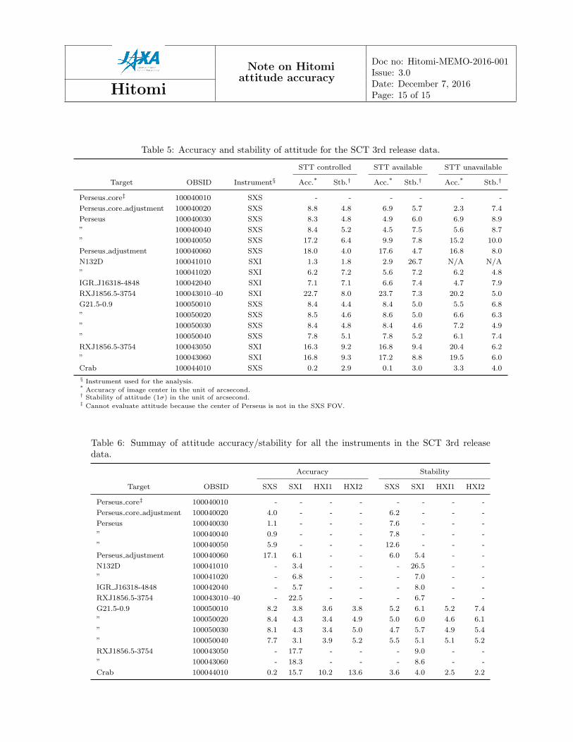
The resultant attitude accuracy and stability are summarized in Table 5. The accuracy and stability of eachavailable instrument, extracted from the cleaned data regardless of the STT availability, are shown in Table 6.The event data for all “STT controlled”, “STT available” and “STT unavailable” in Table 5 are combined tocalculate the values in Table 6.
Note on Hitomiattitude accuracy
Doc no: Hitomi-MEMO-2016-001Issue: 3.0
Hitomi Date: December 7, 2016Page: 15 of 15
Table 5: Accuracy and stability of attitude for the SCT 3rd release data.
STT controlled STT available STT unavailable
Target OBSID Instrument§ Acc.* Stb.† Acc.* Stb.† Acc.* Stb.†
Perseus core‡ 100040010 SXS - - - - - -
Perseus core adjustment 100040020 SXS 8.8 4.8 6.9 5.7 2.3 7.4
Perseus 100040030 SXS 8.3 4.8 4.9 6.0 6.9 8.9
” 100040040 SXS 8.4 5.2 4.5 7.5 5.6 8.7
” 100040050 SXS 17.2 6.4 9.9 7.8 15.2 10.0
Perseus adjustment 100040060 SXS 18.0 4.0 17.6 4.7 16.8 8.0
N132D 100041010 SXI 1.3 1.8 2.9 26.7 N/A N/A
” 100041020 SXI 6.2 7.2 5.6 7.2 6.2 4.8
IGR J16318-4848 100042040 SXI 7.1 7.1 6.6 7.4 4.7 7.9
RXJ1856.5-3754 100043010–40 SXI 22.7 8.0 23.7 7.3 20.2 5.0
G21.5-0.9 100050010 SXS 8.4 4.4 8.4 5.0 5.5 6.8
” 100050020 SXS 8.5 4.6 8.6 5.0 6.6 6.3
” 100050030 SXS 8.4 4.8 8.4 4.6 7.2 4.9
” 100050040 SXS 7.8 5.1 7.8 5.2 6.1 7.4
RXJ1856.5-3754 100043050 SXI 16.3 9.2 16.8 9.4 20.4 6.2
” 100043060 SXI 16.8 9.3 17.2 8.8 19.5 6.0
Crab 100044010 SXS 0.2 2.9 0.1 3.0 3.3 4.0
§ Instrument used for the analysis.* Accuracy of image center in the unit of arcsecond.† Stability of attitude (1σ) in the unit of arcsecond.‡ Cannot evaluate attitude because the center of Perseus is not in the SXS FOV.
Table 6: Summay of attitude accuracy/stability for all the instruments in the SCT 3rd releasedata.
Accuracy Stability
Target OBSID SXS SXI HXI1 HXI2 SXS SXI HXI1 HXI2
Perseus core‡ 100040010 - - - - - - - -
Perseus core adjustment 100040020 4.0 - - - 6.2 - - -
Perseus 100040030 1.1 - - - 7.6 - - -
” 100040040 0.9 - - - 7.8 - - -
” 100040050 5.9 - - - 12.6 - - -
Perseus adjustment 100040060 17.1 6.1 - - 6.0 5.4 - -
N132D 100041010 - 3.4 - - - 26.5 - -
” 100041020 - 6.8 - - - 7.0 - -
IGR J16318-4848 100042040 - 5.7 - - - 8.0 - -
RXJ1856.5-3754 100043010–40 - 22.5 - - - 6.7 - -
G21.5-0.9 100050010 8.2 3.8 3.6 3.8 5.2 6.1 5.2 7.4
” 100050020 8.4 4.3 3.4 4.9 5.0 6.0 4.6 6.1
” 100050030 8.1 4.3 3.4 5.0 4.7 5.7 4.9 5.4
” 100050040 7.7 3.1 3.9 5.2 5.5 5.1 5.1 5.2
RXJ1856.5-3754 100043050 - 17.7 - - - 9.0 - -
” 100043060 - 18.3 - - - 8.6 - -
Crab 100044010 0.2 15.7 10.2 13.6 3.6 4.0 2.5 2.2
Related Documents