South Dakota Damage Analysis South_Dakota_Damage_Analysis.docx 3 October 2010 Page 121 Hit 26 – Turret III Barbette From the BuShips damage report: 36. An estimated 14-inch projectile passed through both sides of hatch coaming 1-128 and detonated upon hitting the barbette of Turret III at frame 123-1/2 about 17 inches from the top. The 17.3-inch armor was gouged to a depth of about 1-1/2 inches over an area of 15 inches in diameter. Surface cracks covered this area and vertical cracks developed in the armor to a distance of 8 feet aft of the point of impact. The blast blew a hole in the main deck 3 feet wide extending around the barbette for a distance of 10 feet. Around the hole the main deck was dished down 8 feet from the barbette between frames 121 and 130. Some fragments were deflected down and aft riddling the starboard side of bulkhead 129 in numerous places between main deck and second decks including one hole 26 inches by 35 inches. Some fragments continued on through C-204L on the starboard side of the barbette considerable damage was done to equipment, mess tables, and ventilation ducts. The armored second deck defeated all fragments. Fragments and blast deflected upward from the point of impact demolished gas seal and water shed for 30 feet around the circumference of the barbette, gouged the gun sleeves of the right and center gun of Turret III and ignited the gun bloomers. Some difficulty was experienced in training the turret after the hit but it was believed that the turret was still able to fire. Fragments ranging aft on main deck damaged 20 mm guns, ready service boxes, gun shields, starboard catapult, and fire plug 1- 133-2. Other fragments spreading forward pierced the superstructure on the main and first superstructure deck. 97 From South Dakota’s action report: [From “Summary of Outstanding Events” section of Action Report] All batteries ceased firing after 0110, shortly after turret three reported training trouble because of a shell hit somewhere near the gas seal ring. This hit was later identified as a fourteen inch shell hit from fragments recovered in that area, and the size of the indentation in the barbette. 98 - - - [From “Chronological Log of the Battle” section of Action Report] 0110 Engagement broken off, proceeding at full speed on course 235°T. Ship’s repair parties and personnel not essential at damage stations fighting fires, caring for wounded and estimating damage done. Observed splashes on wake 1000 yards astern. No enemy ships observed firing. Possibly one of those left burning. 99 - - - 97 BuShips War Damage Report # 57, page 10 98 USS South Dakota Action Report, page 3 99 USS South Dakota Action Report, page 8. These parting shots may have been from Atago, which had switched fire back to South Dakota around this time after shooting at Washington. Atago Direct Action Report.

Welcome message from author
This document is posted to help you gain knowledge. Please leave a comment to let me know what you think about it! Share it to your friends and learn new things together.
Transcript

South Dakota Damage Analysis
South_Dakota_Damage_Analysis.docx 3 October 2010 Page 121
Hit 26 – Turret III Barbette
From the BuShips damage report:
36. An estimated 14-inch projectile passed through both sides of hatch coaming 1-128 and
detonated upon hitting the barbette of Turret III at frame 123-1/2 about 17 inches from the top.
The 17.3-inch armor was gouged to a depth of about 1-1/2 inches over an area of 15 inches in
diameter. Surface cracks covered this area and vertical cracks developed in the armor to a
distance of 8 feet aft of the point of impact. The blast blew a hole in the main deck 3 feet wide
extending around the barbette for a distance of 10 feet. Around the hole the main deck was dished
down 8 feet from the barbette between frames 121 and 130. Some fragments were deflected down
and aft riddling the starboard side of bulkhead 129 in numerous places between main deck and
second decks including one hole 26 inches by 35 inches. Some fragments continued on through
C-204L on the starboard side of the barbette considerable damage was done to equipment, mess
tables, and ventilation ducts. The armored second deck defeated all fragments. Fragments and
blast deflected upward from the point of impact demolished gas seal and water shed for 30 feet
around the circumference of the barbette, gouged the gun sleeves of the right and center gun of
Turret III and ignited the gun bloomers. Some difficulty was experienced in training the turret
after the hit but it was believed that the turret was still able to fire. Fragments ranging aft on main
deck damaged 20 mm guns, ready service boxes, gun shields, starboard catapult, and fire plug 1-
133-2. Other fragments spreading forward pierced the superstructure on the main and first
superstructure deck.97
From South Dakota’s action report:
[From “Summary of Outstanding Events” section of Action Report]
All batteries ceased firing after 0110, shortly after turret three reported training trouble
because of a shell hit somewhere near the gas seal ring. This hit was later identified as a
fourteen inch shell hit from fragments recovered in that area, and the size of the indentation
in the barbette.98
- - -
[From “Chronological Log of the Battle” section of Action Report]
0110 Engagement broken off, proceeding at full speed on course 235°T. Ship’s repair parties
and personnel not essential at damage stations fighting fires, caring for wounded and
estimating damage done.
Observed splashes on wake 1000 yards astern. No enemy ships observed firing. Possibly
one of those left burning.99
- - -
97
BuShips War Damage Report # 57, page 10 98
USS South Dakota Action Report, page 3 99
USS South Dakota Action Report, page 8. These parting shots may have been from Atago, which had switched fire back to
South Dakota around this time after shooting at Washington. Atago Direct Action Report.

South Dakota Damage Analysis
South_Dakota_Damage_Analysis.docx 3 October 2010 Page 122
[From “Enemy Forces” section of Action Report]
The column of four ships which illuminated the SOUTH DAKOTA sustained heavy
casualties. The leading ship, presumed to be a battleship, was seriously damaged and
undoubtedly set on fire. It may be that this ship fired its last gesture salvo at SOUTH
DAKOTA which scored a fourteen inch hit on the barbette of turret III at the end of the
action.100
- - -
[From list of fires]
22. Bloomers, Turret III, ignited by hit in barbette. Extinguished by decontamination
party. 101
- - -
[From list of damage in Enclosure D]
Deck and starboard side of turret 3 between frames 121 and 130, 8’ out from turret, are
bent down next to turret. Hole beside turret in this area is 3’ wide by 10’ long with the
center of the hole about frame 123.
Hatch coaming of hatch 1-122 has a semi-circular cut on both sides 15” deep.
Ventilation intake for system 3-126 has screen blown in.
Deck between frames 110 and 134 are splintered by shrapnel.
Starboard side of #3 barbette has plating dished in 1½” over an area of 15” in diameter aft
of seam. Circular cracks extending over this area. Vertical cracks extend aft 8’ around
barbette.
Davit holder besides hatch 1-128 bent and twisted.
Hatch coaming around hatch 1-128 is torn, twisted, and cut by many pieces of shrapnel.
Gas seal on turret 3 torn and twisted for 30’ on front of turret.
Gun 3 slide pitted with shrapnel.
Two ladders torn from turret base.
Ammunition box aft of turret 3 and by starboard 20 mm gun shields pierced by shrapnel
and all bent and twisted.
Amidships splinter shield has 4 holes that are 4” in diameter.
One hole 12” by 14” and one hole 10” by 10”.
Fire Plug 1-133-2 sheared off at plug.
30 caliber airplane ready ammunition box at frame 133 completely wrecked.
Starboard aft 20 mm gun wrecked. Spare barrel holders torn off shield. Ammunition
boxes torn and twisted.
Recovery boom and vertical brace cut by shrapnel.
40 mm deck plates badly warped and buckled, port and starboard.
100
USS South Dakota Action Report, page 11. It should be noted here that Kirishima was not the lead ship in the Japanese
formation nor was any of her damage inflicted by South Dakota. Atago, which was the lead Japanese ship in the formation and
which had been struck by gunfire from South Dakota, was not seriously damaged in this battle. 101
USS South Dakota Action Report, page 15

South Dakota Damage Analysis
South_Dakota_Damage_Analysis.docx 3 October 2010 Page 123
Hatch 1-139-1 and scuttle badly warped and twisted.102
SECOND DECK
[Second deck bulkheads 136 to ships Scullery at frame 129]
Watertight door 2-136-1, hole 2” by 1”, 6” from bottom.
1” hole 2’ from top through sheeting.
Frame 136 – hit by shrapnel. 2 bad dents beside door in “I” beam. 3” x 1” holes 2’ to port of door
2-136-1, 3” from deck.
Bad dent 1’ above “I” beam, dented just above deck. Bad dent 4” in diameter 1” deep beside door,
3’ above deck, wire cable cut above door next to overhead. Also hole 4” x 1 ½”. Ventilation
supply C-322L pierced by shrapnel. 2 holes in line with door 6” by 10” in diameter. Another
small in duct 6’ above deck.
2 bad dents in supporting stanchion at frame 134 starboard, at edge of scullery.
Air deflector broken by small pieces of shrapnel, starboard side aft of galley.
10” by 2” hole after starboard corner of scullery just above deck. Steam line through starboard
side of compartment has several holes in lagging, also may be in the lines.
Stanchion at frame 131, starboard side of scullery has two dents 1½’ above deck. 4 holes in
scullery, 19” by 3”, 2 x 1” holes and 1 ½” by 4” hole.103
[Second deck around door 2-129-1 and barbette]
4 steam lines carried away, 2 temporarily repaired. Large hole starboard side of door 2-129-1, is
26” by 38”. 11 other holes at this side of door in same area are about 10’ by 4’ from deck.
Watertight door 2-129-1 bent and cut and is damaged beyond repair.
Door frame 2-129-1 bent and bulkhead and side of door frame dished in 6”. 3 holes near deck 3’
from starboard of door are 12” by 4” and 10” by 3”.
Inboard table leg in scullery at frames 129 cut and bent.
2 steam lines to coffee urn damaged. Coffee urn has 2 holes 1” x ½” and also many small holes.
Lagging of large steam line on overhead torn at frame 128.
2 “I” frames starboard side of door 2-129-1 badly cut and dented with one pushed against
bulkhead.
Air escape for C-917V bent and distorted and almost flattened in some spots. Lagging on large
steam lines on overhead torn at frame 128.
3 “I” frames on port side of door, one is slightly dented, one is badly bent and dented to port side
and the other is cut and bent.
Several electrical cables cut just above deck at frame 129 and cable cut 7’ above deck and above
hatch 2-128. 1 steam and one fresh water line cut in this area.
4” x 2” and 1” diameter holes in 440 power panel (2-128-1).
Hole in back panel and dent in bulkhead. 2 electrical cables cut beside hole.
20’ of exhaust C414T carried away. The remainder pierced by numerous pieces of shrapnel.
102
USS South Dakota Action Report, Enclosure D, page 11 103
USS South Dakota Action Report, Enclosure D, page 11

South Dakota Damage Analysis
South_Dakota_Damage_Analysis.docx 3 October 2010 Page 124
Exhaust system 3-126, 10’ carried away between deck and overhead beside turret. Remainder
badly bent and cut, 15’ area.
Supply duct C-201L pierced in 2 places. One hole 10” x 12”. One hole 2” in diameter.
Frame 127. Motor blown off one power shell hoist. Hoist half way off track. Roller track badly
bent and out of line.
20’ of mess tables around barbette missing. Also angle iron supports missing.
Hatch 2-128-2 retaining edge for gasket badly distorted and cut on starboard side.
Curved I beam around barbette. 10’ carried away from frames 123 to 125. Distorted and cut 20’
forward and 10’ aft.
Armored deck bent down 4’ into compartment. Hole beside barbette 2 ½’ by 12’.
Bounding bar cut and bent 20’, (1” by 3”).
Two (2) degaussing cables badly cut and torn.
Drain line beside hatch 1-122 cut in two places by shrapnel.
Wire cage pierced in two places around ladder. Switch box on cage broken.
Supply vent C-603E, one 1” diameter hole.
Supply vent to C609E badly bent, also ripped near overhead.
Fire main above plug 2-119-1 pierced by shrapnel. Hole 2” x 1”.
Nozzle and bracket bent by shrapnel.
Hole in Galley bulkhead 119, 7’ above deck, hole 6” x 4”.
Frame 114, centerline 3rd deck, 1 electrical cable cut by fire.
Frame 113, overhead starboard side hatch 3-113-2 – 2 electrical cables cut by fire.
Circular cracks area 6” below deck main deck, frame 122.
Water seal above main deck dented and pulled away from rivets 4’ at frame 125 starboard side of
barbette.
Athwartship “I” beams – frame 123 and 126, beams damaged 8’ from barbette at frame 125, bent
twisted 4’ x 6’ more slightly bent down from deck.
Vent motor at frame 121 damaged.
Scuttlebutt damaged at frames 122, several holes in top. Small pieces shrapnel hit motor and
compressor below. 104
- - -
GUNNERY DAMAGE
[Damage to gun turret # 3]
(d) Turret #3.
Received hit by 14” projectile in armor about 17” from top of barbette on starboard side.
Turret was trained in this direction. Projectile was deflected downward through deck.
Fragments caused damage as follows:-
Gas seal and water shed disrupted.
Sleeve of right gun badly scarred and gouged so sleeve was removed to make gun
serviceable.
Gun hoop received shallow indentation through sleeve.
Center gun sleeve gouged but still serviceable.
Right and center guns – securing strips for bucklers damaged.105
104
USS South Dakota Action Report, Enclosure D, page 12

South Dakota Damage Analysis
South_Dakota_Damage_Analysis.docx 3 October 2010 Page 125
[From list of equipment damaged or destroyed by gun fire]
The depression stops on #3 turret were moved out of position by shell fire, therefore the D.S.
[Depression Stop] circuit in #3 turret was made inoperative.106
Analysis of impact
This hit was from the last or one of the last salvos fired by Kirishima and her gunners deserve credit for
still making their shots count even though their ship was wrecked and on fire by this time. The
description of the damage for this impact was written in a difficult way to follow and only two
photographs were used in the original BuShips report to illustrate the damage from this hit. There has
never been a question as to caliber of the projectile that caused this damage, estimated by BuShips as 14-
inch, but the type of 14-inch projectile was not given in the damage report.
The original authors of the BuShips report probably only used the two photographs they supplied in their
report to make their conclusions. The first line in their report makes the association that the shell passed
through both sides of Hatch 1-128 and then struck the barbette. However, the South Dakota’s action
report does not mention the hatch. In addition, there are two hatches, 1-122 and 1-128, that are listed as
damaged in the report without any notes as to the causes of the damage, so once again the damage report
is very confusing in the way it was written. By using more USN photographs of the original damage
along with some recent photographs taken aboard USS Alabama of these same areas, we hope to be able
to place into context what was really damaged by this impact and what type of shell caused it.
105
USS South Dakota Action Report, Enclosure D, page 14 106
USS South Dakota Action Report, Enclosure D, page 19

South Dakota Damage Analysis
South_Dakota_Damage_Analysis.docx 3 October 2010 Page 126
Hatch 1-122
Figure 85 – Hit 26 – Turret III and Hatch 1-122 on USS Alabama
Photograph of USS Alabama copyrighted by Robert Lundgren
The photograph in Figure 85 was taken aboard USS Alabama and shows Hatch 1-122 in relation to Turret
III. The damage listed in South Dakota’s damage report is that there was a 15-inch deep semi-circular cut
on both sides of the hatch. Though the BuShips report labeled this hatch as 1-128 in their report, most
people believe they were actually referring to Hatch 1-122. Hatch 1-122 measures 56 inches wide x 96
inches long by 12 inches high. The forward edge lines up with frame 122 with the center seam of the
barbette at frame 123.5. The aft side of the hatch is at frame 124. The distance from the inboard side of
the hatch to the barbette is 118 inches. This matches the copies of USS South Dakota’s builder’s
blueprints which were used for the damage report. The flange seen over the barbette is 7.5 inches wide
and the distance from the deck to the bottom of the flange is 21.0 inches. The total height of the barbette
measured from the top of the flange to the main deck is 28.5 inches at the center seam or frame 123.5.

South Dakota Damage Analysis
South_Dakota_Damage_Analysis.docx 3 October 2010 Page 127
Hatch 1-128Forward flange destroyed by impact
Gun sleeve under bloomer
Figure 86 – Hit 26 – Turret III and Hatch 1-128 on USS Alabama
Photograph of USS Alabama copyrighted by Robert Lundgren
The photograph in Figure 86 was also taken aboard the USS Alabama and shows the relationship of Hatch
1-128 to the forward edge of the barbette. The damage listed for this hatch in South Dakota’s report is as
follows: “Davit holder besides [sic] Hatch 1-128 bent and twisted. Hatch coaming around Hatch 1-128 is
torn, twisted, and cut by many pieces of shrapnel.” The forward edge of this hatch lines up with ship
Frame 128. The barbette itself runs from frames 118.5 to 128.5 and each frame is 4 feet wide.

South Dakota Damage Analysis
South_Dakota_Damage_Analysis.docx 3 October 2010 Page 128
Figure 87 – Hit 26 – Damage to Turret Face
This photograph of South Dakota (Figure 87) shows that the forward flange, normally at the bottom of the
turret face, has been destroyed and the steel bent up, which means that the blast occurred underneath the
flange. In addition, two of the ladders have been blown off the face of the turret. Only the far left ladder
remains attached of which the lower legs can still be seen on the right side of Figure 87. The turret in this
photograph has been turned back to the centerline, which is why there is no deck damage seen in this
photograph. The bloomers were reported to have caught fire after the explosion.

South Dakota Damage Analysis
South_Dakota_Damage_Analysis.docx 3 October 2010 Page 129
Figure 88 – Hit 26 – Damage to right gun sleeve
Figure 88 shows the damage to the right gun sleeve, which has been removed to make the gun
serviceable. The damage to the gun sleeves and lack of damage to the gun barrels themselves indicates
that the blast took place directly under these components. In all likelihood, the right gun was directly over
the blast and the blast was then directed up and against the barbette itself. The right gun hoop received
shallow indentations through the sleeve due to the fragment damage. The center gun sleeve also took
damage but the gun was able to remain in service.
South Dakota Damage Analysis
South_Dakota_Damage_Analysis.docx 3 October 2010 Page 130
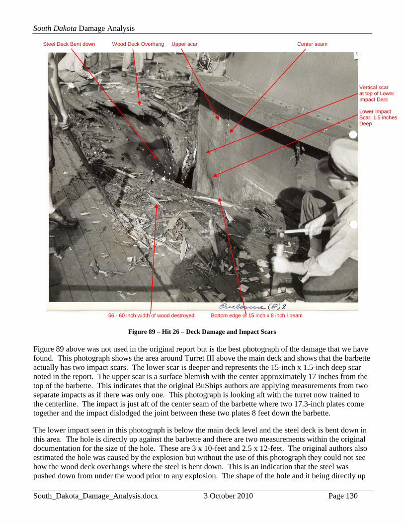
Figure 89 – Hit 26 – Deck Damage and Impact Scars
Figure 89 above was not used in the original report but is the best photograph of the damage that we have
found. This photograph shows the area around Turret III above the main deck and shows that the barbette
actually has two impact scars. The lower scar is deeper and represents the 15-inch x 1.5-inch deep scar
noted in the report. The upper scar is a surface blemish with the center approximately 17 inches from the
top of the barbette. This indicates that the original BuShips authors are applying measurements from two
separate impacts as if there was only one. This photograph is looking aft with the turret now trained to
the centerline. The impact is just aft of the center seam of the barbette where two 17.3-inch plates come
together and the impact dislodged the joint between these two plates 8 feet down the barbette.
The lower impact seen in this photograph is below the main deck level and the steel deck is bent down in
this area. The hole is directly up against the barbette and there are two measurements within the original
documentation for the size of the hole. These are 3 x 10-feet and 2.5 x 12-feet. The original authors also
estimated the hole was caused by the explosion but without the use of this photograph they could not see
how the wood deck overhangs where the steel is bent down. This is an indication that the steel was
pushed down from under the wood prior to any explosion. The shape of the hole and it being directly up
Wood Deck Overhang
Lower Impact Scar, 1.5 inches Deep
Steel Deck Bent down Upper scar
56 - 60 inch width of wood destroyed
Vertical scar at top of Lower Impact Dent
Bottom edge of 15 inch x 8 inch I beam
Center seam

South Dakota Damage Analysis
South_Dakota_Damage_Analysis.docx 3 October 2010 Page 131
against the barbette are important clues to determining just what happened. In addition the riveted
structure between the barbette and the deck supports has been pulled away and down, popping the rivet
heads but leaving the steel strakes intact. There are no apparent fragments that penetrated the 1.5-inch
STS steel.
The area of wood planking damage seen in this photograph is relatively small. There are about 14 or 15
four-inch wide planks shown damaged in this photograph, giving a width of 56 or 60 inches of damaged
deck area as noted in Figure 89. There would be 7 planks remaining before the outer limit of the hole is
reached so this means that the hole is approximately 28 to 32 inches wide, which is close to the 2.5 foot x
12 foot measurement given in South Dakota’s action report. Looking closely at the lower scar, there is a
vertical scar from the top of the dent and a different color line that runs through the top of the dent which
will help identify this impact scar in other photographs. The different color line that runs through this
scar also marks the lower edge of a circular 15 inch x 8 inch I-Beam that supports the main deck, which
will help estimate the distance below the main deck that the center of the lower impact was. The lighter
color band on the barbette is where the main deck was pressed up against the barbette and marks the
original deck level. Based on the documentation in the reports, the deck and Athwartship I-beams 123
and 126 underneath was bent down out to 8 feet from the barbette and then severely bent down the last 3
feet.
Figure 90 – Hit 26 – Upper Impact Scar
Figure 90 is a close up of the upper scar damage to the plate. This photograph was used in the original
BuShips report and may have been the only one of two that the original authors used. The top of the
flange at the very top of the barbette can be seen in the upper right corner of the photograph. The vertical
seam and right side gouge can also be seen along with the lines that marked where the main deck used to
be. This scar did not significantly dent the armor and resulted in surface flaking of the plate with deeper
cracks at the center. If viewed by itself this photograph would suggest that the impact was made by a HE
shell due to the lack of damage to the plate surface.

South Dakota Damage Analysis
South_Dakota_Damage_Analysis.docx 3 October 2010 Page 132
Bent downAthwartship I beam 126
Remains of Circular I beam
Center of lower impact
Circular cracks radiate out
From center of lower
Impact
Paint line Marked bottom edge
Vertical scar at top of gouge
Outer Diameter
Outer Diameter
Main deck pushed down
of circular I beam
1.5 " x 15" scar
Figure 91 – Hit 26 – Lower Impact Scar
Figure 91 is the second photograph used in the original report. This shows the lower impact site looking
up from the 2nd
deck level. The photograph is looking aft and shows that Athwartship I-beam 126 has
been bent down and the remains of the circular I-beam it supported that surrounded the barbette. The
main deck has been pushed down and the center of the lower gouge (marked with an X) is approximately
4” below the original line that marked the bottom edge of the circular I-beam. It also shows circular
cracks on the surface of the Class “A” plate that radiate out from this impact and a minor vertical scar at
the top of the gouge which can be seen in the photograph looking at the scars from above the main deck.
These are the circular cracks documented in South Dakota’s report, which is quoted here: “Starboard side
of #3 barbette has plating dished in 1.5” over an area of 15” in diameter aft of seam. Circular cracks
extending over this area.”
Concentric cracks in the brittle face of Class “A” armor are virtually always seen when a face-hardened
plate is impacted hard enough to make a significant dent or hole in it. The surface layer is extremely
brittle and the shock waves rippling outward along the face and those going into the plate and reflecting
from the plate back or hard-face-to-soft-back plate boundary cause a Moiré (interference) Pattern on the
surface where they null and reinforce each other, which is why the cracks seem to be so evenly spaced.
This is a very important clue because it shows that the 17.3-inch Class “A” plate took a major shock
South Dakota Damage Analysis
South_Dakota_Damage_Analysis.docx 3 October 2010 Page 133
below the normal level of the main deck. These cracks show that the shell body impacted here and not at
the upper scar at 17 inches below the top of the barbette.
The center of the impact is approximately 4 inches below where the original bottom edge of the circular I-
beam that supported the main deck was. This places the center of the lower impact at 20.5 inches below
the top of the 1.5-inch STS steel weather deck and this is approximately 51 inches from the top of the
barbette as measured from the top of the flange to the center of this impact site.
Badly bent down
Circular cracks Center seam
Circular I beam
Athwartship I beam 123
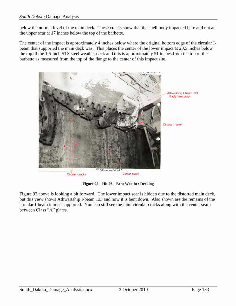
Figure 92 – Hit 26 – Bent Weather Decking
Figure 92 above is looking a bit forward. The lower impact scar is hidden due to the distorted main deck,
but this view shows Athwartship I-beam 123 and how it is bent down. Also shown are the remains of the
circular I-beam it once supported. You can still see the faint circular cracks along with the center seam
between Class “A” plates.

South Dakota Damage Analysis
South_Dakota_Damage_Analysis.docx 3 October 2010 Page 134
Athwartship I beam 123
Circular cracks
Rivets pulled out
Vert ical seam Remains of circular I beam
Figure 93 – Hit 26 – Remains of Circular I-beam
This closer look in Figure 93 shows how the riveted structure between the circular I-beam and the
barbette was pulled apart with many rivet holes remaining intact. This view also shows how the circular
cracks crossed over the seam between the two plates and that the circular I-beam itself was twisted and
ripped in half. Athwartship I-beams 123 and 126 were bent down 8 feet out from barbette with the last 3-
4 feet being severely bent down.
The following photographs were taken aboard sister-ship USS Alabama to give an idea of how the same
area on USS South Dakota would have looked before the battle.

South Dakota Damage Analysis
South_Dakota_Damage_Analysis.docx 3 October 2010 Page 135
Circular I beam 15 x 8 inches
Athwartship I beam 123
Longitude I beam
Figure 94 – Hit 26 – Athwartship I-beam 123 on USS Alabama
Photograph of USS Alabama copyrighted by Robert Lundgren
Figure 94 shows Athwartship I-beam 123 which is seen supporting the 15 x 8 inch circular I-beam that
surrounds the barbette. The small angle irons seen attached to the circular I-beam are supports for the
mess tables that surround the barbette and do not imply any vertical support for the circular I-beam itself.
Barbette
7.5 inch gap between 15 x 8 inch I beam and barbette
Bottom of 15 x 8 inch I beam
Weather seal
Figure 95 – Hit 26 – Circular I-beam and Barbette on USS Alabama
Photograph of USS Alabama copyrighted by Robert Lundgren
South Dakota Damage Analysis
South_Dakota_Damage_Analysis.docx 3 October 2010 Page 136
Figure 95 shows the gap between the circular I-beam and the barbette itself. The riveted structure attaching
this I-beam to the main deck will be ripped down as seen in the damage photographs. The deck is not directly
attached to the barbette but is sealed with a weather seal and pressed up against the barbette. The upper
strength decks of the hull girder (main and second deck) are relieved of supporting the massive weights of the
turrets. These weights are taken up by the platform decks, the ships sides, and the keel. In this way when the
ship sags or hogs the upper strength decks are not bent by these actions. The armored weather deck, by
being pressed so tightly up against the barbette, assists in holding the barbette structure rigid from lateral
movements like when the ship heels or rolls. This however does leave a natural weak spot where the deck can
be pushed down if the impact is heavy enough.
I beam 126Bulkhead 129
Door 2-129-1
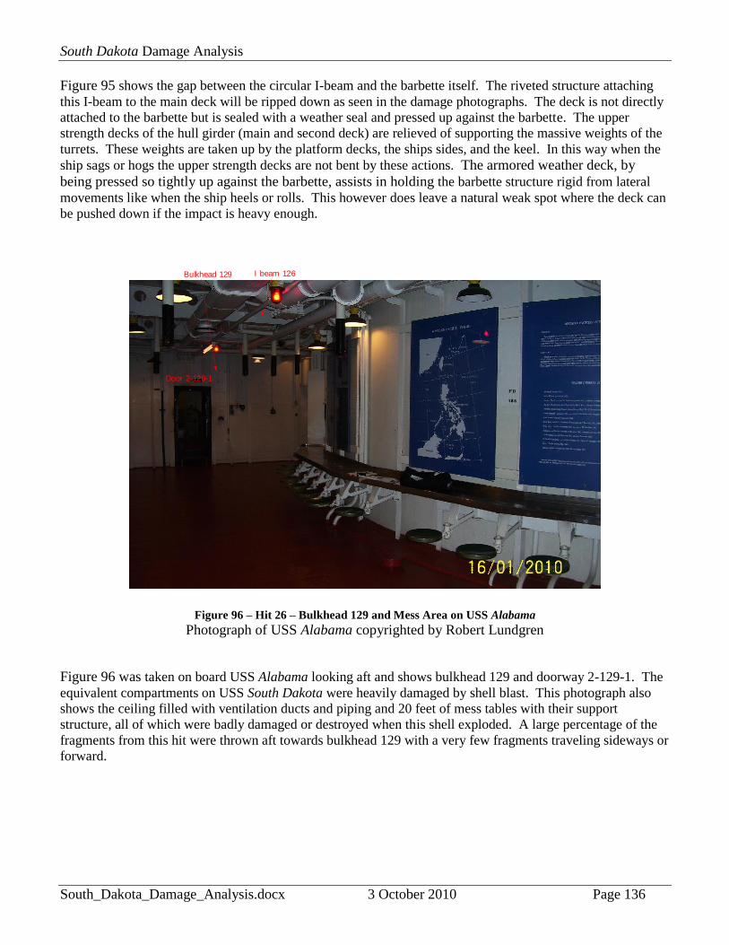
Figure 96 – Hit 26 – Bulkhead 129 and Mess Area on USS Alabama
Photograph of USS Alabama copyrighted by Robert Lundgren
Figure 96 was taken on board USS Alabama looking aft and shows bulkhead 129 and doorway 2-129-1. The
equivalent compartments on USS South Dakota were heavily damaged by shell blast. This photograph also
shows the ceiling filled with ventilation ducts and piping and 20 feet of mess tables with their support
structure, all of which were badly damaged or destroyed when this shell exploded. A large percentage of the
fragments from this hit were thrown aft towards bulkhead 129 with a very few fragments traveling sideways or
forward.

South Dakota Damage Analysis
South_Dakota_Damage_Analysis.docx 3 October 2010 Page 137
Figure 97 – Hit 26 – Damage to Bulkhead 129
Figure 97 taken aboard the USS South Dakota shows the damage to bulkhead 129 and the size of the
fragments. The large hole is probably the 26 inch x 35 inch hole documented in the report. There appear
to be scars on the armored second deck where fragments were deflected through the bulkhead. The I-
beams have been twisted and some cut.
South Dakota Damage Analysis
South_Dakota_Damage_Analysis.docx 3 October 2010 Page 138
Bulkhead 129
Hatch to 3rd deck
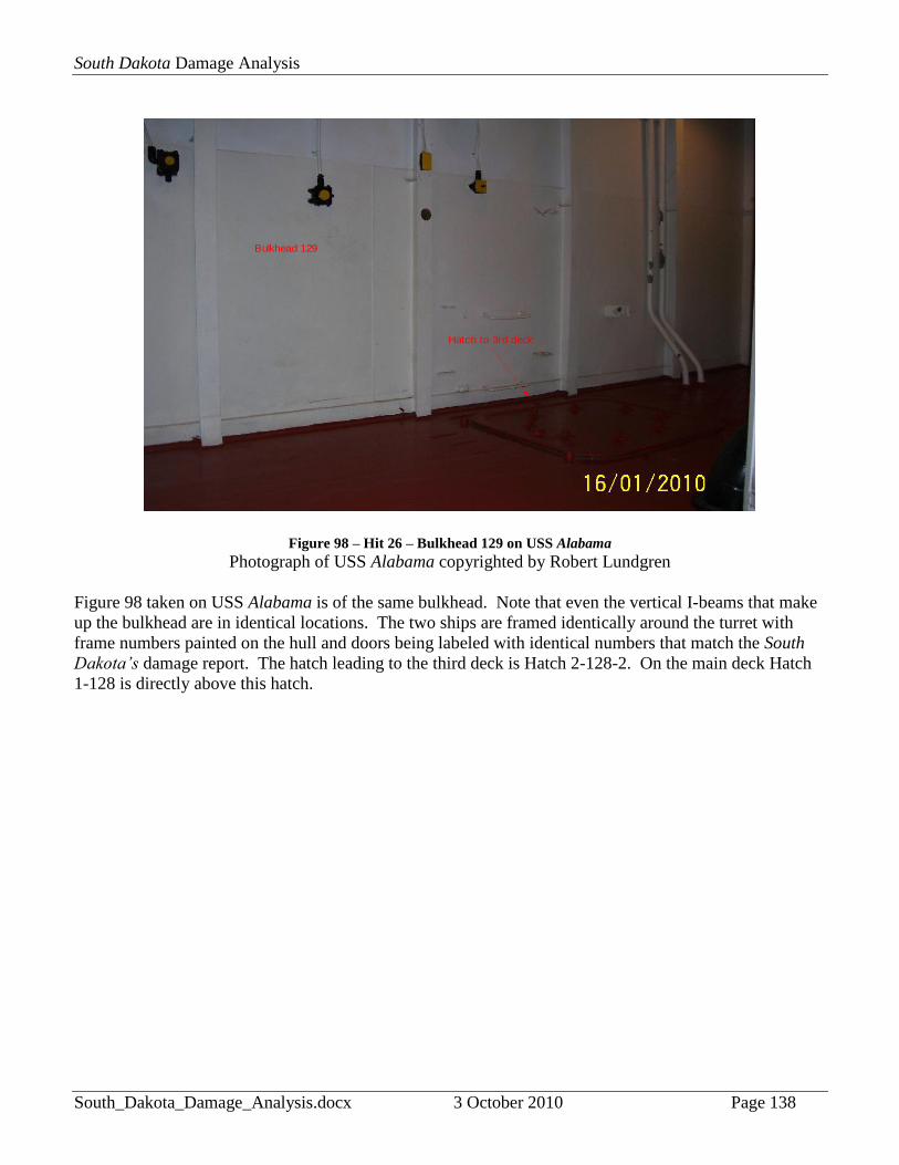
Figure 98 – Hit 26 – Bulkhead 129 on USS Alabama
Photograph of USS Alabama copyrighted by Robert Lundgren
Figure 98 taken on USS Alabama is of the same bulkhead. Note that even the vertical I-beams that make
up the bulkhead are in identical locations. The two ships are framed identically around the turret with
frame numbers painted on the hull and doors being labeled with identical numbers that match the South
Dakota’s damage report. The hatch leading to the third deck is Hatch 2-128-2. On the main deck Hatch
1-128 is directly above this hatch.

South Dakota Damage Analysis
South_Dakota_Damage_Analysis.docx 3 October 2010 Page 139
Bulkhead 129
2-129-1
Scullery
Figure 99 – Hit 26 – Scullery near Bulkhead 129 on USS Alabama
Photograph of USS Alabama copyrighted by Robert Lundgren
Figure 99 and Figure 101 show the ship’s scullery on the opposite side of Bulkhead 129 as seen on board
USS Alabama and give an idea of how the same area on USS South Dakota may have appeared.
C-204LStern
Bow
Turret 3
Scullery
Fragments Penetrated Bulkhead 129
Continued and penetrated bulkhead of C204L starboard sideImpact Point
USS South Dakota 2nd Deck
Figure 100 – Hit 26 – Fragment Pattern between Barbette and Frame 129

South Dakota Damage Analysis
South_Dakota_Damage_Analysis.docx 3 October 2010 Page 140
Looking aft in scullery Frame 131
Figure 101 – Hit 26 – Scullery near Frame 131 on USS Alabama
Photograph of USS Alabama copyrighted by Robert Lundgren
Figure 101 shows the scullery looking aft. The wire screen is at Frame 131. Fragments ripped through
this area damaging the kitchen supplies.
Stanchion 134
Stanchion 131
Scullery
Figure 102 – Hit 26 – Aft of Scullery on USS Alabama
Photograph of USS Alabama copyrighted by Robert Lundgren
Figure 102 shows the compartment aft of the scullery. Both Stanchion 131 and Stanchion 134 on South
Dakota took damage as did the ventilation ducts seen in the overhead.

South Dakota Damage Analysis
South_Dakota_Damage_Analysis.docx 3 October 2010 Page 141
Bulkhead 136
Door 2-136-1
Stanchion 134
Figure 103 – Hit 26 – Bulkhead 136 on USS Alabama
Photograph of USS Alabama copyrighted by Robert Lundgren
Figure 103 shows Bulkhead 136 and Door 2-136-1 which were both damaged by fragments. Bulkhead
136 was the farthest that any fragments traveled from the blast point on the barbette, some of which
penetrated this bulkhead.

South Dakota Damage Analysis
South_Dakota_Damage_Analysis.docx 3 October 2010 Page 142
Figure 104 – Hit 26 – Damage to Roller Path
Figure 104 shows the center seam between Class “A” plates within the barbette and the twisted and bent
roller path that gave the turret difficulty in training after the battle. This damage was most likely caused
by shock either by the impact force or by the explosion transmitted through the 17.3-inch Class “A” plate
that protected the roller path.
Determining the true shell trajectory was one of the first obstacles for the analysis of this impact.
BuShips assertion that the projectile passed through Hatch 1-122 and then struck the barbette gives us two
impact points on the ship from which we can determine which impact obliquity angles were possible and
then using the track chart for the ships movements determine the range and time Kirishima, the hatch, and
the barbette line up. The hatch begins at Frame 122 and ends at Frame 124. The center seam of the
barbette is at Frame 123.5 with the projectile hitting the barbette just aft of the center seam. Zero degrees
is the normal line to the barbette face at a right angle to the impact site. For the shell to pass through this
hatch and strike where it did on the barbette, it can be shown that the range of possible impact angles runs
from +25 to +50 degrees as illustrated in Figure 105.

South Dakota Damage Analysis
South_Dakota_Damage_Analysis.docx 3 October 2010 Page 143
25 degrees0 degrees
50 degrees
BowStern
Impact obliquity angle
(where 0 degrees = right angle impact)
Turret was facing to starboard
Normal line to barbet te face at impact point
Figure 105 – Hit 26 – Shell Trajectories and Impact Point if shell hit Hatch 1-122
The times that Kirishima, Hatch 1-122 and the barbette line up are between 0101-0103 with the maximum
range of 7,500 yards to as short as 5,600 yards At 7,500 yards the angle of elevation is 4.0 degrees and
angle of fall 4.63 degrees. At 5,600 yards the angle of elevation 2.89 degrees and angle of fall 3.23
degrees.107
After 0103 Kirishima, the hatch and the impact site will never line up again based on the two
ship’s track charts. This is the first inconsistency. Captain Gatch was very specific that this impact
occurred at 0110 near the end of the engagement. Either the impact occurred earlier than Captain Gatch
knew or the shell trajectory did not pass through the hatch.
107
All ballistic calculations were done with MS QuickBasic 4.5 computer EXTERIOR BALLISTICS 6G1109. 100 fps were
removed from new gun velocity to mimic extreme wear on liners (worst case scenario). Type 1 AP data with adjusted Form
Factor of 1.0864. Kirishima started the battle with reduced charges purposely to avoid more wear on the liners so she could
stay at the front lines longer before she was forced to go back to Japan to get them re-lined.
South Dakota Damage Analysis
South_Dakota_Damage_Analysis.docx 3 October 2010 Page 144
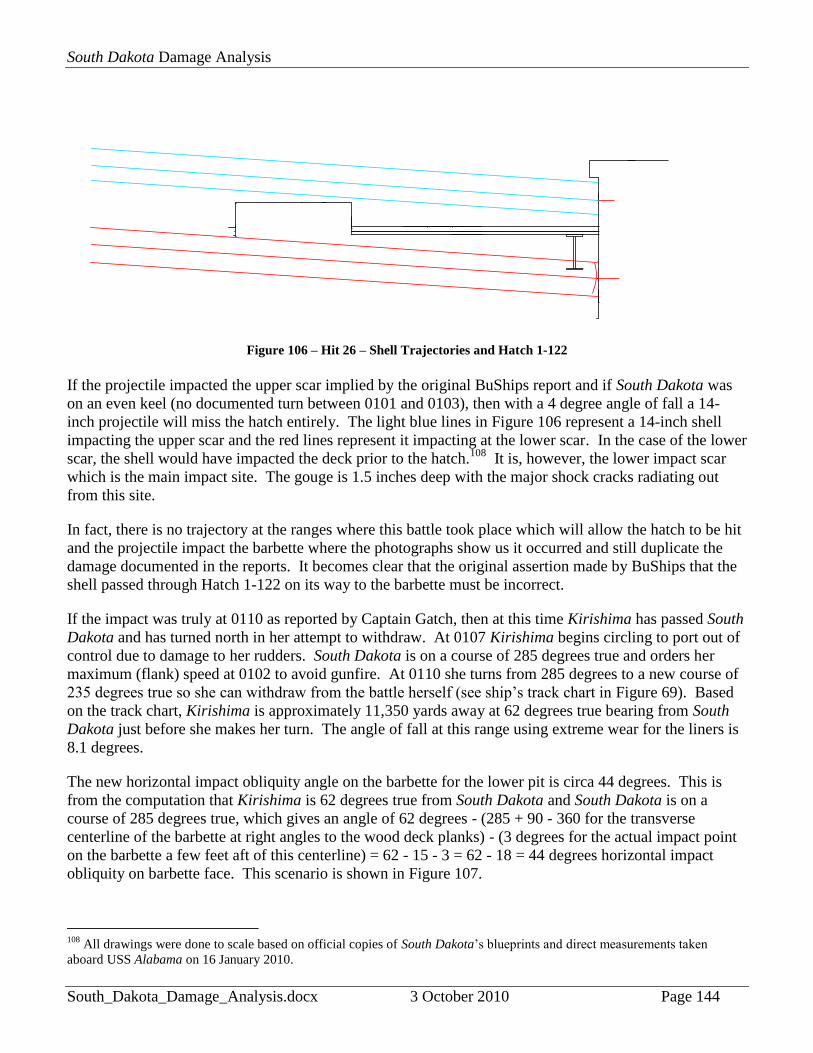
Figure 106 – Hit 26 – Shell Trajectories and Hatch 1-122
If the projectile impacted the upper scar implied by the original BuShips report and if South Dakota was
on an even keel (no documented turn between 0101 and 0103), then with a 4 degree angle of fall a 14-
inch projectile will miss the hatch entirely. The light blue lines in Figure 106 represent a 14-inch shell
impacting the upper scar and the red lines represent it impacting at the lower scar. In the case of the lower
scar, the shell would have impacted the deck prior to the hatch.108
It is, however, the lower impact scar
which is the main impact site. The gouge is 1.5 inches deep with the major shock cracks radiating out
from this site.
In fact, there is no trajectory at the ranges where this battle took place which will allow the hatch to be hit
and the projectile impact the barbette where the photographs show us it occurred and still duplicate the
damage documented in the reports. It becomes clear that the original assertion made by BuShips that the
shell passed through Hatch 1-122 on its way to the barbette must be incorrect.
If the impact was truly at 0110 as reported by Captain Gatch, then at this time Kirishima has passed South
Dakota and has turned north in her attempt to withdraw. At 0107 Kirishima begins circling to port out of
control due to damage to her rudders. South Dakota is on a course of 285 degrees true and orders her
maximum (flank) speed at 0102 to avoid gunfire. At 0110 she turns from 285 degrees to a new course of
235 degrees true so she can withdraw from the battle herself (see ship’s track chart in Figure 69). Based
on the track chart, Kirishima is approximately 11,350 yards away at 62 degrees true bearing from South
Dakota just before she makes her turn. The angle of fall at this range using extreme wear for the liners is
8.1 degrees.
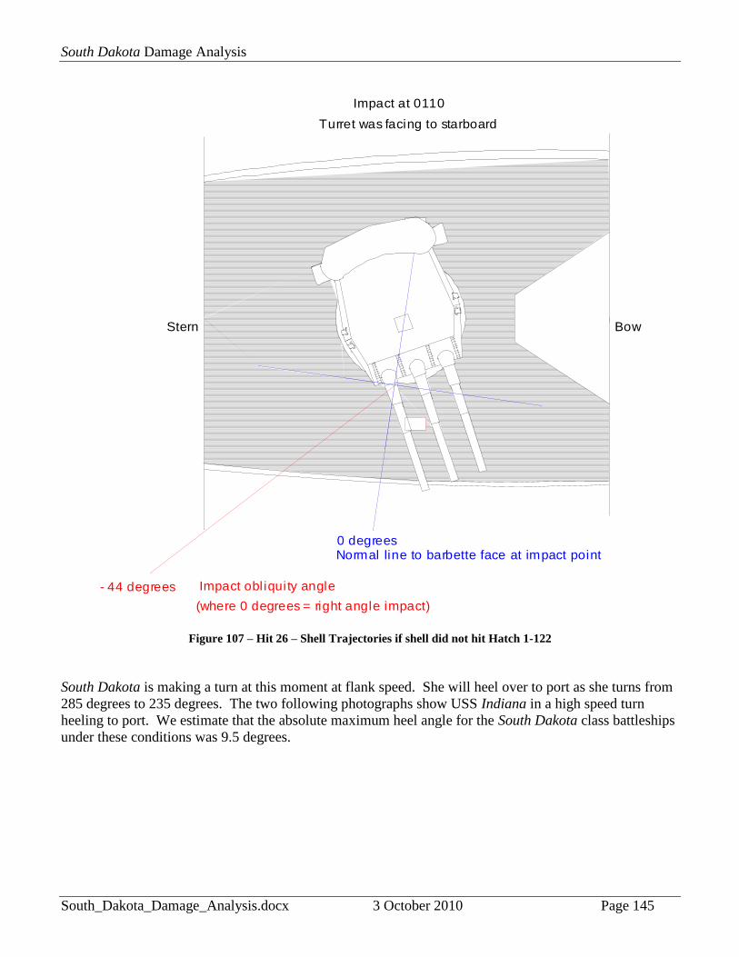
The new horizontal impact obliquity angle on the barbette for the lower pit is circa 44 degrees. This is
from the computation that Kirishima is 62 degrees true from South Dakota and South Dakota is on a
course of 285 degrees true, which gives an angle of 62 degrees - (285 + 90 - 360 for the transverse
centerline of the barbette at right angles to the wood deck planks) - (3 degrees for the actual impact point
on the barbette a few feet aft of this centerline) = 62 - 15 - 3 = 62 - 18 = 44 degrees horizontal impact
obliquity on barbette face. This scenario is shown in Figure 107.
108
All drawings were done to scale based on official copies of South Dakota’s blueprints and direct measurements taken
aboard USS Alabama on 16 January 2010.
South Dakota Damage Analysis
South_Dakota_Damage_Analysis.docx 3 October 2010 Page 145
0 degrees
BowStern
Normal line to barbette face at impact point
Impact obl iquity angle
(where 0 degrees = right angle impact)
Turret was facing to starboard
- 44 degrees
Impact at 0110
Figure 107 – Hit 26 – Shell Trajectories if shell did not hit Hatch 1-122
South Dakota is making a turn at this moment at flank speed. She will heel over to port as she turns from
285 degrees to 235 degrees. The two following photographs show USS Indiana in a high speed turn
heeling to port. We estimate that the absolute maximum heel angle for the South Dakota class battleships
under these conditions was 9.5 degrees.

South Dakota Damage Analysis
South_Dakota_Damage_Analysis.docx 3 October 2010 Page 146
Figure 108 – Hit 26 – Starboard side view of USS Indiana heeling during turn
USN Photograph courtesy of NavSource.com

South Dakota Damage Analysis
South_Dakota_Damage_Analysis.docx 3 October 2010 Page 147
Figure 109 – Hit 26 – Bow view of USS Indiana heeling during turn
USN Photograph courtesy of NavSource.com
At this range of 11,350 yards, the angle of fall is 8.1 degrees (EB6.0G calculation), so the total angle is
9.5 (heel angle) + 8.1 (Angle of fall) = 17.6 degrees. Since the impact angle is now 44 degrees offset in
the horizontal plane, coming from the stern the shell would impact the main deck about 78 inches from
the barbette and strike the barbette approximately 24.7 inches below the steel deck (78 * TAN(17.6) =
24.7 inches). However, the impact resistance with the deck will also force the nose of the shell up
approximately 3.0 inches and this places the center of the impact at the lower site to within 1.0 inch of our
estimated depth. We used a worst case scenario, however, the effect of such small variations can be
easily compensated by the spread in other estimated values, such as the possible upward curve of the nose
due to the deck – perhaps it was 4 inches and not 3 inches, which would compensate for a steeper heel
angle, or 2 inches which would account for a lesser heel angle – or else the shell was yawing slightly due
to the worn gun, so the nose was tilted down about a degree, adding to the effective angle of fall (at small
angles of yaw, a yaw of 1 degree can be replaced by an actual change in the trajectory by 0.5 degree in
that direction with similar effects on the penetration calculations). Thus, for every minor tweak in one
direction, we could have a tweak in another direction. The fact that this worst case scenario comes within
1.0 inch of our estimated depth shows that the principles used for this trajectory are valid.

South Dakota Damage Analysis
South_Dakota_Damage_Analysis.docx 3 October 2010 Page 148
The best estimate for the shell type that resulted in this damage is a 14-inch Type 1 AP projectile. The
main deck was not blown down due to an explosive force but pushed down by the weight, velocity, and
frontal density of the projectile impacting the deck. The wood deck overhang seen in Figure 89 again
shows us how the steel was pushed down from under the wood. The shell impacting the deck
approximately 78 inches away begins to bend the deck down and tear the weather seal and riveted
structure away from the surface of the barbette. A simple analogy is the pull tab on a large soup can.
When you lift the tab up the front edge of the tab forces the lid’s lip into a large “smiley-face” arc. In the
case of the barbette, the arc is in the opposite direction because the deck is outside the barbette and the lid
for the soup can is on the inside of the can but the principle is the same.
Figure 110 – Hit 26 – Tin Can demonstration of AP projectile impact
Replace Pull Tab with AP projectile and the principles remain the same.
When the shell impacted the deck it would lose its windscreen, cap head, and AP cap due to the extremely
high obliquity impact with the 1.5-inch STS deck. However, the cap head and AP cap, continuing along,
but now at a shallow upward angle (the shell’s 44-degree horizontal obliquity angle to the lower barbette
impact point) would bounce off the barbette above the deck level near the upper blemish point (which had
not been formed yet) at almost exactly 90 degrees from the original direction of motion – for an impact
that does not penetrate deeply, as these light-weight cap pieces could not against the hard, thick barbette
face, the angle of reflection is very close to the incoming angle, just going the other way on the far side of
the normal (right-angles) line through the impact point, which turns out to be in a direct line with Hatch 1-
122. Thus, they hit the hatch moving away from the barbette and slightly upward, causing the semi-
circular holes in the hatch as they fly outward to end up in the ocean. As the remaining shell nose and
body moved forward and down, it struck the barbette at the lower impact site. However, at 44 degrees,
this angle is much higher than the test proof angle for a Japanese Type 1/91 AP shell (any size), which
were only proof tested to 20 degrees from right angles, resulting in the projectile having its nose tip snap
off and eliminating any possibility of penetrating the barbette more than the tiny 1.5 inch deep notch at
South Dakota Damage Analysis
South_Dakota_Damage_Analysis.docx 3 October 2010 Page 149
the lower impact site.109
Usually, this nearly horizontal impact would cause the projectile to ricochet
slightly downward and mostly sideways away from the barbette, much like the AP cap and cap head
mentioned above, but the deck prevents this motion by pinning the projectile nose to the barbette in the
horizontal direction. The nose bends the deck away from the barbette as it tries to ricochet, but it is
constrained to move almost straight down by the deck resistance, since this is the only direction that the
deck will (relatively) easily bend under the force of the projectile nose from above. The result is the 28 to
32-inch width of the slot between the barbette and bent-down deck edge in the center where the projectile
impact was, narrowing like a smile in either direction parallel to the barbette face until the deck is no
longer bent at roughly 5-6 feet to either side of the projectile impact point.
The lower body of the projectile pivots up as the nose is forced down until the projectile is, in effect,
standing on its nose with the broken tip sticking into the space beneath the bent weather deck and the base
slammed up against the barbette near that upper “blemish” point just below the turret. This base-end
rotation is so fast and violent that it is like a baseball bat hitting a home run (a rather extreme form of
“base slap,” as this lower body impact against the armor is termed in the US Navy). Since the armor's 1-
inch-deep “cemented” face is about 650 Brinell hardness (approaching the hardness of hardened machine
cutting tool steel), backed up by a circa 35% deep face of circa 500 Brinell, then another 20% dropping in
a ski-slope curve to the circa 225 Brinell ductile back layer to the back surface of the plate (this last of
“merely” bank vault steel hardness), the barbette armor face is essentially absolutely rigid and the rather
soft lower body of the projectile flattens out against it as if the projectile was made from soft clay. A
comparison of USN and Japanese hardening patterns for 14-inch AP projectiles is shown below in Figure
111.
109
Japanese 14-inch and 16.1-inch projectiles were proof tested to 20 degree impact angles and the 18.1-inch were proof tested
to 30 degree impact angles against plates only about 2/3rds of the projectile's diameter of Vickers Cemented (VC) face-
hardened belt armor made before World War I – circa 9-inch plate for the 14-inch shells, 11-inch plate for the 16.1-inch shell,
and 12-inch plate for the 18.1-inch shell. The 18.1-inch shell was not significantly better than the smaller rounds against
proportionately thicker plate or at higher obliquity.

South Dakota Damage Analysis
South_Dakota_Damage_Analysis.docx 3 October 2010 Page 150
Figure 111 – Hit 26 – Differences between USA and Japanese 14-inch projectiles
This base slap causes the lower body to crush the explosive filler in from the barbette-impact side, where there
is virtually no anti-shock cushion – only the upper end of the filler cavity has a heavy cushion to protect the
filler from detonation on impact against thick armor head-on – for the very sensitive circa-1.5% (by weight)
TNA filler. This causes the filler to detonate like British “Lyddite” (Japanese “Shimose”) explosive did under
similar impacts during World War I, acting just like it had been set off properly by a base fuze. This contact
blast with the barbette at the upper blemish mark forms the surface damage pattern shown in the picture of that
upper damage area on the barbette, with its irregular shock cracks and the small dislocations of the armor
plates that have a joint very close to this spot (this is what caused the turret to be considered out of action due
to the roller bearing path at the top of the barbette being misaligned, making turret traverse difficult). There is,
however, no dent or pit in the barbette face at this upper blast point, it being merely slightly flattened and
actually looks polished as the blast scoured off any surface lumps and removed the paint there.
This rotation and base slap is similar to what occurred for Hit 17. In both of these hits, the projectile nose
failed to penetrate the final plate hit (the barbette for Hit 26 and the rear of gun mount for Hit 17) and the
projectile nose was locked to the plate face (by the bent-down deck for Hit 26 and by being partially punched
through the plate in Hit 17) at or near the initial impact point at a high angle (yaw angle circa 45 degrees in Hit
17 and obliquity angle in Hit 26) and rotated to end up broadside to and slammed up against the plate face
(vertically nose-down in Hit 26 and horizontally nose to the right in Hit 17). In Hit 26 the shell slammed up
against the unyielding barbette face and detonated and in Hit 17 it made a shallow dent in the thinner, ductile
gun mount armor and remained intact. We think that these results against the plates that finally stopped the
shells are very similar, regardless of any motion prior to the final impact.

South Dakota Damage Analysis
South_Dakota_Damage_Analysis.docx 3 October 2010 Page 151
Heavily Damaged Right Gun
Blast Point Blemish
Initial impact point
Main Deck
2nd Deck
5.3" + 0.75" STS Armor
Barbette 17.3" Class "A" Armor
Several Large, Slow Nose & Upper Body Pieces
Turret Transverse
Deep cracks and flaked face
Many Shallow Cracks
Barbette Plate joint edges
dislodgedConcentric Cracks
Main Deck bent down prior to explosion
Rivets snapped & plate edge split near center
but no holes made in deck plate by fragments
Many small, fast shell fragmentssprayed above deck
14-inch Type 1 Projectile
pressed up against barbette,
broken with nose moving downward
Wood overhang
1.5" dimplein armor surface
Centerline & 17.3"Armor Plate Joint
2.0" Teak Deck on 1.5" STS Armor
Hole spaced from barbette s ide
Jet of large, slow Base Plug & Base Ring pieces
Figure 112 – Hit 26 – Base Slap Diagram
With half of the shell below the main deck and the other half above the main deck and the shell in a vertical position pressed up against the
barbette, we get the above main deck fragment pattern described in the report. The right gun was probably directly over the blast point with the
base fragments being blasted up into the gun sleeve.

South Dakota Damage Analysis
South_Dakota_Damage_Analysis.docx 3 October 2010 Page 152
Scullery
2nd Deck
Fragment Pattern
2nd deck deflected fragm ents
Turret 3
Main Deck
Wood overhangFR 136 FR 134 FR 131 FR 129
Figure 113 – Hit 26 – Fragment Damage Pattern below the Main Deck
The fragment pattern below the main deck is largely traveling aft due to the curvature of the barbette as shown above in Figure 113 and earlier in
Figure 100. The size of the fragments that would create the holes in bulkhead 129 as seen in Figure 97 are huge but are also relatively few in
number. These could only have been produced by the large nose pieces of a fragmented AP projectile. The armored second deck deflected all
fragments and some of these fragments had enough mass and energy to be able to penetrate bulkheads as far aft as bulkhead 136.

South Dakota Damage Analysis
South_Dakota_Damage_Analysis.docx 3 October 2010 Page 153
When examining the other two types of 14-inch projectiles fired by Kirishima, the Type 0 HE and the Type 3
Incendiary AA shell; the Type 3 would have begun to break up on impact with the deck and, with its large
wood nose adapter, is totally incapable of causing the type of fragment damage found here. Its small powder
charge is also incapable of producing the type of blast damage found for this hit so this type of shell can be
quickly eliminated as a possibility.
For the Type 0 HE, the way the BuShips damage report originally described this impact as passing through
Hatch 1-122, impacting the barbette 17 inches from the top, and then detonating and blowing a 3 foot by 10
foot hole into the deck, has led many to believe this impact was made by a HE projectile. A closer
examination of this idea as described above shows why this is not possible. Had a HE shell detonated
horizontally to the deck, the damage around the barbette would have been greatly different. The impact from
this type of shell would have given a shallow oval dent over a wider area, with no wood left for several feet on
all sides, especially sideways. It would have created a small, irregular, roughly oval hole in the deck under the
center of the shell, surrounded by many tiny holes and dents up close to the big hole which would have been
caused by fragments going mostly sideways. The deck edge up against the barbette would have been bent up
slightly as it had the most reinforcement from underneath and it would not have been bent down as much as
directly under the explosion point. There would not have been any way for any projectile pieces other than a
few tiny middle-body fragments from going below the weather deck, with only deck pieces blown out causing
any major damage below the deck, and those being thrown straight down, not sideways. The likely damage
caused by a HE shell is shown in Figure 114.
Figure 114 – Hit 26 – Projected Shape of Hole if HE Projectile Detonated over Deck
A Type 0 HE projectile is 4 feet long which places the center of the explosive force two feet away from
the barbette surface. If the shell struck the upper impact scar 17 inches from the top of the barbette, then
it would produce an open air explosion over the deck which would have caused the deck to dish. There
would be no wood overhanging where the steel is bent down and the 64-pound TNA filler is not powerful
enough to produce a 10 to 12 foot long hole in the 1.5-inch STS steel deck. The shell body of a HE

South Dakota Damage Analysis
South_Dakota_Damage_Analysis.docx 3 October 2010 Page 154
projectile will never reach the barbette because when the fuze is crushed the shell will destroy itself
almost instantaneously.
Transverse I beams
Longitude I beam
Circular I beam
Hatch 1-122
Center of explosion
Forces applied to deck
Deck dished
64 lbs T NA Fil ler
Figure 115 – Hit 26 – Likely Damage from HE Projectile Detonating over Main Deck
For the deck to get bent down and the hole to be directly up against the barbette surface due to an
explosive force, the center of the charge must be placed directly up against the barbette and on the deck.
The charge weight to produce such a large hole between 10 and 12 feet long in the 1.5-inch STS steel
would need to be in the order of 200-300 lbs. of HE explosive. This size burster is impossible for a
Japanese 14-inch Type 0 projectile.
Transverse I beams
Longitude I beam
Circular I beam
Hatch 1-122
200-300 Lbs Packed HE Explosive
Required to bend 1.5" STS deck
Forces applied to deckDeck bends down
Figure 116 – Hit 26 – Explosive Force required to bend Main Deck
We can compare Hit 11, which was made by a 14-inch Type 0 projectile striking on a 1.25-inch STS
plate, and the deck area for Hit 26 to show how the damaged plates differ.

South Dakota Damage Analysis
South_Dakota_Damage_Analysis.docx 3 October 2010 Page 155
Table 3
Hit 11 compared to Hit 26
Hit 11 Hit 26
Big, irregular hole blown in 1.25-inch STS plate
right at the impact point.
No holes made in 1.5-inch STS plate whatsoever;
just torn-out rivets.
Radiating cracks (especially one long horizontal
crack due to a defect in the plate hit) and a shallow
dish around the blast point.
No cracks and no dish; just a deeply curled down
deck edge directly in front of the shell nose,
bending down the edge to either side somewhat,
too. Note that there is NO denting/dishing of the
deck at all behind or directly to the sides the
impact point in a circa-200-degree-wide arc
centered on the hypothetical HE projectile's rear,
which is impossible if a horizontal shell explosion
were to blame, as most of the explosion effect of a
HE shell is sideways from the center of the shell,
where the main explosive charge is, not forward,
where the narrow pointed nose is, so the deepest
dent in the deck should be sideways (directly down
and in an arc to either side), not in front of the shell,
if a nearly horizontal HE shell caused the damage.
Many small pits and partial/complete middle-body
fragment holes closely surrounding the central big
hole.
Again, no holes made other than the existing rivet
holes.
Center of damage is at shell impact point, radiating
more-or-less in all directions, damaging the
impacted plate the most right in the center where
the blast was strongest.
Center of damage to the deck is the curled-down deck
edge in front of a HE shell’s narrow nose, well away
from the main blast center of the shell, which is the
lower and middle body, even though the deck about 3
feet away from the barbette would be directly under
this center of the explosion if it was caused by a
nearly horizontal HE shell detonating a few inches
above that deck upon hitting the barbette. There is no
evidence whatsoever of such a close-to-the-deck
detonation, which would have left some kind of huge
mark on the deck top surface, even if somehow no
holes were made – an explosion sure made a distinct
mark on the much more solid barbette face just above
the deck!

South Dakota Damage Analysis
South_Dakota_Damage_Analysis.docx 3 October 2010 Page 156
Hit 11 Hit 26
Chunks of HE projectile and armor tore holes in the
next thin HTS bulkhead inboard, being stopped by
the main recessed Class “A” belt armor. Thus, the
explosion and its fragments were powerful enough
to tear through thin high-tensile steel plate even
after punching through 1.25 inches of STS plate.
There were unsupported undamaged wood planks
of the over-deck with only broken tips
overhanging the bent-down deck region. A HE
explosion that could tear holes in steel plate behind
an STS armor plate, as in Hit #11, and which could
also bend down 1.5-inch STS over a 10-12-foot-
wide arc to a depth of 3 to 4 feet (this is typical
World War II Tank Armor thickness, remember!),
would have torn up the wood over-deck at a much
farther distance than the distance it could bend
armor steel plate. There could not possibly be
overhanging wood planks in such a case.
These inconsistencies show that the damage was not caused by a HE projectile detonating horizontal to
the deck and that BuShip’s original analysis was incorrect. Another consideration that also enters into
this analysis is the fact that a Japanese nose-fuzed HE projectile simply does not have the capability of
gouging a 1.5-inch deep gash in the face-hardened armor plate of the barbette. In other words, Japanese
HE projectiles could not penetrate any thick, rigid Class “A” plate more than a slight flaking of the
cemented surface layer caused by the burster exploding at point-blank range. There would be no deep
conical pit in the armor as is the case for this hit. This alone can eliminate the HE shell type from
consideration. Also, the only projectile type that could produce a Moiré (interference) Pattern due to
reflected impact shock waves bouncing off the plate’s rear surface, back into the brittle face layer, is from
an AP projectile.
The fragment size and distribution also needs to be considered. A HE projectile, due to its larger shell
cavity and thinner sides, breaks up into hundreds of small fragments with only a few large pieces coming
from the base section. The actual projectile in this case produced many large fragments that passed
through the scullery and through bulkhead 136. The fragment pattern for Hit 26 is typical of AP
ammunition and inconsistent with HE ammunition.
Although not conclusive, the fact that this hit was from one of the last shots fired by Kirishima at a known
battleship target would tend to make one surmise that the Japanese gunners had by now used up the Type
3 AA and Type 0 HE rounds already in the guns and hoists at the start of the battle and were by now
firing AP rounds at this end stage of the battle.
When everything listed above is considered for Hit 26, the only projectile that fits all of the available
evidence is the 14-inch Type 1 AP shell. This hit represents the only time in US Naval History that a US
battleship was struck by a foreign battleship’s main-caliber AP projectile and in this case South Dakota
and her designers won the age-old contest between shell and armor.110
110
For an earlier work by Nathan Okun on Hit 26, please see his essay on the subject at the NavWeaps Naval Technical Board.
South Dakota Damage Analysis
South_Dakota_Damage_Analysis.docx 3 October 2010 Page 157
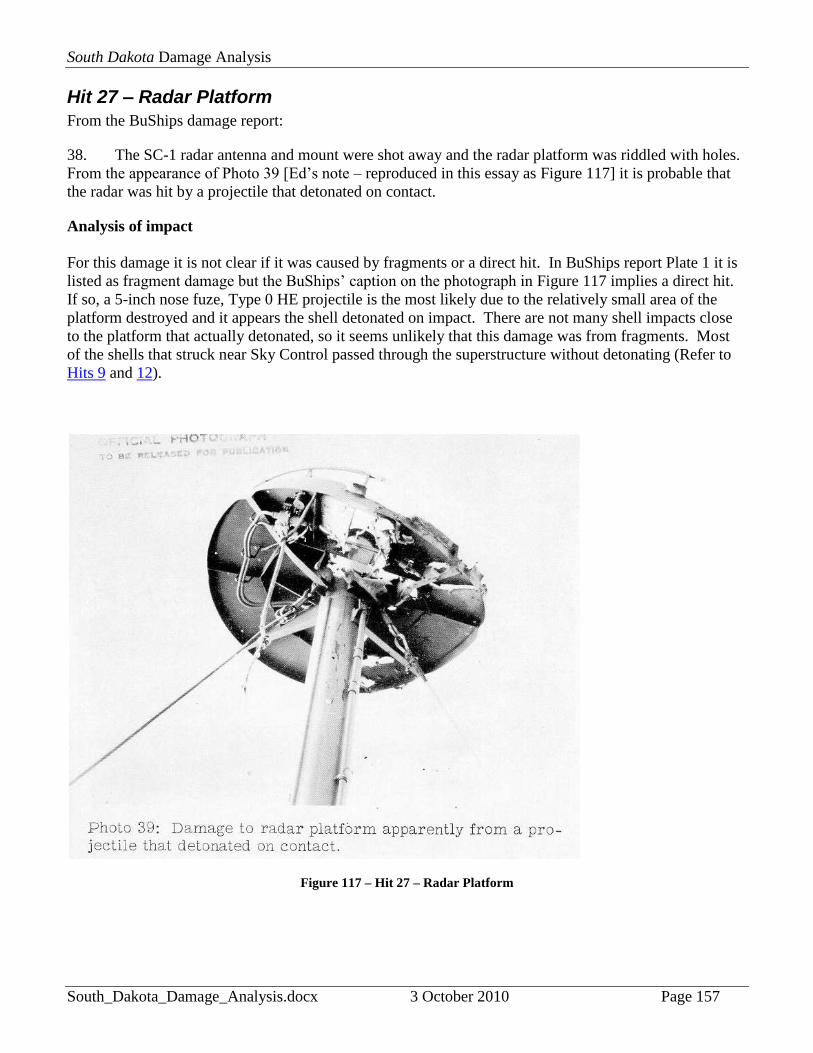
Hit 27 – Radar Platform
From the BuShips damage report:
38. The SC-1 radar antenna and mount were shot away and the radar platform was riddled with holes.
From the appearance of Photo 39 [Ed’s note – reproduced in this essay as Figure 117] it is probable that
the radar was hit by a projectile that detonated on contact.
Analysis of impact
For this damage it is not clear if it was caused by fragments or a direct hit. In BuShips report Plate 1 it is
listed as fragment damage but the BuShips’ caption on the photograph in Figure 117 implies a direct hit.
If so, a 5-inch nose fuze, Type 0 HE projectile is the most likely due to the relatively small area of the
platform destroyed and it appears the shell detonated on impact. There are not many shell impacts close
to the platform that actually detonated, so it seems unlikely that this damage was from fragments. Most
of the shells that struck near Sky Control passed through the superstructure without detonating (Refer to
Hits 9 and 12).
Figure 117 – Hit 27 – Radar Platform
Related Documents