TRINITRON ® COLOR TELEVISION SERVICE MANUAL BX-1L CHASSIS MODEL NAME REMOTE COMMANDER DESTINATION CHASSIS NO. 9-883-732-01 KV-29FS150 RM-YA005 LATIN NORTH SCC-S79I-A KV-29FS150 RM-YA005 LATIN SOUTH SCC-S79J-A HISTORY INFORMATION FOR THE FOLLOWING MANUAL: ORIGINAL MANUAL ISSUE DATE: 1/2007 REVISION DATE SUBJECT 1/2007 No revisions or updates are applicable at this time.

Welcome message from author
This document is posted to help you gain knowledge. Please leave a comment to let me know what you think about it! Share it to your friends and learn new things together.
Transcript

TRINITRON® COLOR TELEVISION
SERVICE MANUAL BX-1L CHASSIS MODEL NAME REMOTE COMMANDER DESTINATION CHASSIS NO.
9-883-732-01
KV-29FS150 RM-YA005 LATIN NORTH SCC-S79I-A
KV-29FS150 RM-YA005 LATIN SOUTH SCC-S79J-A
HISTORY INFORMATION FOR THE FOLLOWING MANUAL:
ORIGINAL MANUAL ISSUE DATE: 1/2007
REVISION DATE SUBJECT
1/2007 No revisions or updates are applicable at this time.

TRINITRON® COLOR TELEVISION
SERVICE MANUAL BX-1L CHASSIS MODEL NAME REMOTE COMMANDER DESTINATION CHASSIS NO.
9-883-732-01
KV-29FS150 RM-YA005 LATIN NORTH SCC-S79I-A
KV-29FS150 RM-YA005 LATIN SOUTH SCC-S79J-A
Self DiagnosisSupported model
KV-29FS150 RM-YA005

KV-29FS150
KV-29FS150 3
TABLE OF CONTENTS
SECTION TITLE PAGESpecifi cations ....................................................................................................................................................................................................... 4Warnings and Cautions ........................................................................................................................................................................................ 5Safety Check-Out ................................................................................................................................................................................................. 6Self-Diagnostic Function ...................................................................................................................................................................................... 7
SECTION 1: DISASSEMBLY ........................................................................................................................................................................................... 101-1. Rear Cover Removal .................................................................................................................................................................................. 101-2. Chassis Assembly Removal ....................................................................................................................................................................... 101-3. Service Position ...........................................................................................................................................................................................111-4. Picture Tube Removal ................................................................................................................................................................................ 12 Anode Cap Removal Procedure ................................................................................................................................................................. 12
SECTION 2: SET-UP ADJUSTMENTS ............................................................................................................................................................................ 132-1. Beam Landing ............................................................................................................................................................................................ 132-2. Convergence .............................................................................................................................................................................................. 142-3. Focus Adjustment ....................................................................................................................................................................................... 152-4. Screen (G2) ................................................................................................................................................................................................ 16
SECTION 3: CIRCUIT ADJUSTMENTS .......................................................................................................................................................................... 173-1. Remote Adjustment Buttons and Indicators ............................................................................................................................................... 173-2. Accessing the Service Menu ...................................................................................................................................................................... 183-3. Confi rming Service Adjustment Changes ................................................................................................................................................... 183-4. White Balance Adjustments ........................................................................................................................................................................ 183-5. Picture Quality Adjustments ....................................................................................................................................................................... 183-6. Service Data ............................................................................................................................................................................................... 21
SECTION 4: DIAGRAMS ................................................................................................................................................................................................. 314-1. Circuit Boards Location .............................................................................................................................................................................. 314-2. Printed Wiring Board and Schematic Diagram Information ........................................................................................................................ 314-3. Block Diagram ............................................................................................................................................................................................ 324-4. Schematics and Supporting Information .................................................................................................................................................... 33
A Board Schematic Diagram (1 of 6) ......................................................................................................................................................... 33A Board Schematic Diagram (2 of 6) ......................................................................................................................................................... 34A Board Schematic Diagram (3 of 6) ......................................................................................................................................................... 35A Board Schematic Diagram (4 of 6) ......................................................................................................................................................... 36A Board Schematic Diagram (5 of 6) ......................................................................................................................................................... 37A Board Schematic Diagram (6 of 6) ......................................................................................................................................................... 38CV Board Schematic Diagram ................................................................................................................................................................... 40H2 Board Schematic Diagram ................................................................................................................................................................... 42
4-5. Semiconductors .......................................................................................................................................................................................... 44
SECTION 5: EXPLODED VIEWS .................................................................................................................................................................................... 455-1. Chassis ....................................................................................................................................................................................................... 455-2. Picture Tube ............................................................................................................................................................................................... 46
SECTION 6: ELECTRICAL PARTS LIST ........................................................................................................................................................................ 47

KV-29FS150
KV-29FS150 4
SPECIFICATIONS
1) 1 Vp-p 75 ohms unbalanced, sync negative
2) Y: 1Vp-p 75 ohms unbalanced, sync negative
C: 0.286 Vp-p (Burst signal), 75 ohms
3) Y: 1.0 Vp-p, 75 ohms, sync negative; PB: 0.7 Vp-p, 75 ohms;
PR Vp-p, 75 ohms.
4) 500 mVrms (100% modulation), Impedance: 47 kilohms
Design and specifi cations are subject to change without notice.
Television systemAmerican TV standard, NTSC
Channel coverageVHF: 2-13/UHF: 14-69/CATV: 1-125
Antenna75-ohm external antenna terminal for VHF/UHF
Picture tubeFD Trinitron® tube
Visible screen size27-inch picture measured diagonally
Actual screen size29-inch measured diagonally
Supplied AccessoriesRemote Commander RM-YA005Two Size AA (R6) Batteries
Trademarks and Copyrights
As an ENERGY STAR® Partner, Sony Corporation has determined that this product meets the ENERGY STAR® guidelines for energy efficiency. ENERGY STAR® is a U.S. registered mark.
Sony, FD Trinitron, WEGA® , Steady Sound and Intelligent Picture are registered trademarks of Sony Corporation.
!"
! " #$%$
&" '! ("
)*) )+!, .
+/36" 736"
*3.+8" +!:3.+8" "
;368)8;"
.+
/< =

KV-29FS150
KV-29FS150 5
WARNINGS AND CAUTIONS
CAUTION
Short circuit the anode of the picture tube and the anode cap to the metal chassis, CRT shield, or carbon painted on the CRT, after removing the anode.
WARNING!!
An isolation transformer should be used during any service to avoid possible shock hazard, because of live chassis. The chassis of this receiver is directly connected to the AC power line.
! SAFETY-RELATED COMPONENT WARNING!!
Components identifi ed by shading and ! mark on the schematic diagrams, exploded views, and in the parts list are critical for safe operation. Replace these components with Sony parts whose part numbers appear as shown in this manual or in supplements published by Sony. Circuit adjustments that are critical for safe operation are identifi ed in this manual. Follow these procedures whenever critical components are replaced or improper operation is suspected.

KV-29FS150
KV-29FS150 6
SAFETY CHECK-OUT
After correcting the original service problem, perform the following safety checks before releasing the set to the customer:
1. Check the area of your repair for unsoldered or poorly soldered connections. Check the entire board surface for solder splashes and bridges.
2. Check the interboard wiring to ensure that no wires are “pinched” or touching high-wattage resistors.
3. Check that all control knobs, shields, covers, ground straps, and mounting hardware have been replaced. Be absolutely certain that you have replaced all the insulators.
4. Look for unauthorized replacement parts, particularly transistors, that were installed during a previous repair. Point them out to the customer and recommend their replacement.
5. Look for parts which, though functioning, show obvious signs of deterioration. Point them out to the customer and recommend their replacement.
6. Check the line cords for cracks and abrasion. Recommend the replacement of any such line cord to the customer.
7. Check the B+ and HV to see if they are specifi ed values. Make sure your instruments are accurate; be suspicious of your HV meter if sets always have low HV.
8. Check the antenna terminals, metal trim, “metallized” knobs, screws, and all other exposed metal parts for AC leakage. Check leakage as described below.
Leakage Test
The AC leakage from any exposed metal part to earth ground and from all exposed metal parts to any exposed metal part having a return to chassis, must not exceed 0.5 mA (500 microamperes). Leakage current can be measured by any one of three methods.
1. A commercial leakage tester, such as the Simpson 229 or RCA WT-540A. Follow the manufacturers’ instructions to use these instructions.
2. A battery-operated AC milliampmeter. The Data Precision 245 digital multimeter is suitable for this job.
3. Measuring the voltage drop across a resistor by means of a VOM or battery-operated AC voltmeter. The “limit” indication is 0.75 V, so analog meters must have an accurate low voltage scale. The Simpson’s 250 and Sanwa SH-63TRD are examples of passive VOMs that are suitable. Nearly all battery-operated digital multimeters that have a 2 VAC range are suitable (see Figure A).
How to Find a Good Earth GroundA cold-water pipe is a guaranteed earth ground; the cover-plate retaining screw on most AC outlet boxes is also at earth ground. If the retaining screw is to be used as your earth ground, verify that it is at ground by measuring the resistance between it and a cold-water pipe with an ohmmeter. The reading should be zero ohms.
If a cold-water pipe is not accessible, connect a 60- to 100-watt trouble- light (not a neon lamp) between the hot side of the receptacle and the retaining screw. Try both slots, if necessary, to locate the hot side on the line; the lamp should light at normal brilliance if the screw is at ground potential (see Figure B).
To Exposed Metal Parts on Set
0.15 µF 1.5 K Ω ACVoltmeter(0.75 V)
Earth Ground
Trouble Light
AC Outlet BoxOhmmeter
Cold-water Pipe
Figure A. Using an AC voltmeter to check AC leakage. Figure B. Checking for earth ground.

KV-29FS150
KV-29FS150 7
SELF-DIAGNOSTIC FUNCTION
*One fl ash count is not used for self-diagnostic.
*If a +B overcurrent is detected, stoppage of the vertical defl ection is detected simultaneously. The symptom that is diagnosed fi rst by the mircrocontroller is displayed on the screen.**Refer to Screen (G2) Adjustments in Section 2-4. of this manual.
2. Display of STANDBY LED Flash Count
2 times
4 times
5 times
LED ON 0.3 sec.
LED OFF 0.3 sec. LED OFF3 sec.
Standby indicator
Self DiagnosisSupported model
The units in this manual contain a self-diagnostic function. If an error occurs, the STANDBY LED indicator will automatically begin to fl ash. The number of times the LED fl ashes translates to a probable source of the problem. A defi nition of the STANDBY LED fl ash indicators is listed in the instruction manual for the user’s knowledge and reference. If an error symptom cannot be reproduced, the Remote Commander can be used to review the failure occurrence data stored in memory to reveal past problems and how often these problems occur.
1. Diagnostic Test Indicators
When an error occurs, the STANDBY LED indicator will fl ash a set number of times to indicate the possible cause of the problem. If there is more than one error, the indicator will identify the fi rst of the problem areas.Results for all of the following diagnostic items are displayed on screen. No error has occurred if the screen displays a “0”.
DiagnosisItem
Description
• No Power
• +B overcurrent(OCP)
• Vertical NG.
• IK (AKB)
• Supply VoltageProtection
DetectedSymptoms
•Power does not turn on.•No power is supplied to theTV.
•AC power supply is faulty.
•Power does not turn on.•Load on power line isshorted.
•Has entered standby stateafter horizontal raster.
•Vertical deflection pulse isstopped.
•Power line is shorted orpower supply is stopped.
•No raster is generated.•CRT cathode currentdetection reference pulseoutput is small.
•No power supply to CRTANODE.
•No RASTER is generated.
No. of timesSTANDBY
Indicator flashes
Does not light
2 times
4 times
5 times
8 times
Diagnostic Resulton screen display
—
2 OCP:02 OCP:1 ~ 255
4 VSTOP:04 VSTOP:1 ~ 255
5 AKB:05 AKB:1 ~ 255
8 SUP:08 SUP:1 ~ 255
ProbableCause
Location
• Power cord is not pluggedin.
• Fuse is burned out (F4101)(H2 Board)
• H.OUT (Q511) is shorted.(A board)
• IC751 is shorted.(CV Board)
• +13V is not supplied.(A Board)
• IC503 voltage list is faulty.(A Board)
• Video OUT (IC751) is faulty.(CV Board)
• IC001 is faulty. (A Board)• Screen (G2) is improperly
adjusted.
• IC604 faulty.• IC607 faulty.

KV-29FS150
KV-29FS150 8
3. Stopping the STANDBY LED Indicator FlashTurn off the power switch on the TV main unit or unplug the power cord from the outlet to stop the STANDBY LED Indicator from fl ashing.
4. Self-Diagnostic Screen DisplayFor errors with symptoms such as “power sometimes shuts off” or “screen sometimes goes out” that cannot be confi rmed, it is possible to bring up past occurrences of failure on the screen for confi rmation.
To Bring Up Screen TestIn standby mode, press buttons on the Remote Commander sequentially, in rapid succession, as shown below:
DISPLAY Channel 5 Sound Volume - POWER
Note that this differs from entering the Service Mode (Sound Volume + ).
The following screen will be displayed indicating the error count:
SELF DIAGNOSTIC2 OCP : 03 OVP : N/A4 VSTOP : 0 Number “0” means that no fault was detected.5 AKB : 1 Number “1” means a fault was detected one time only.8 SUP : 0101 WDT : N/A
SERIAL: FFFFFFFMODEL: FFFFFFFF
Handling of Self-Diagnostic Screen DisplaySince the diagnostic results displayed on the screen are not automatically cleared, always check the self-diagnostic screen during repairs. When you have completed the repairs, clear the result display to “0”.Unless the result display is cleared to “0”, the self-diagnostic function will not be able to detect subsequent faults after completion of the repairs.
Clearing the Result DisplayTo clear the result display to “0”, press buttons on the Remote Commander sequentially when the diagnostic screen is displayed, as shown below:
Channel 8 0
Quitting the Self-Diagnostic ScreenTo quit the entire self-diagnostic screen, turn off the power switch on the Remote Commander or the main unit.

KV-29FS150
KV-29FS150 9
Self-Diagnostic Circuit
A BOARDIC001
Y/CHROMA JUNGLE
A BOARDIC804V.OUT
A BOARDIC001
SYSTEM
A BOARDIC003
MEMORY
FROMCV BOARDIC751 PIN 5
IK
EHTORED LED
DISPLAY
SDA1
V.GUARDSDA5F.B-PLS 3 1384
32122A BOARD
FROMQ816
COLLECTOR
99
+B overcurrent (OCP) Occurs when an overcurrent on the +B (135V) line is detected by pin 32 of IC001 (A Board). If the voltage of pin 32 of IC001 (A Board) is more than 4V when V.SYNC is more than seven verticals in a period, the unit will automatically turn off. V-Protect Occurs when an absence of the vertical defl ection pulse is detected by pin 13 of IC001 (A Board). Power supply will shut down when waveform interval exceeds 2 seconds. IK (AKB) If the RGB levels* do not balance within 15 seconds after the power is turned on, this error will be detected by IC001 (A Board). TV will stay on, but there will be no picture.Power Supply NG (+5V) for Video Processor Occurs when IC001 internal HV protect detects an abnormal H-Pulse (frequency) due to improper power supply to IC001. The TV cuts off high voltage power of anode CRT. No picture will be detected. eg: faulty IC602 or IC604

KV-29FS150
KV-29FS150 10
1-1. REAR COVER REMOVAL
SECTION 1: DISASSEMBLY
1-2. CHASSIS ASSEMBLY REMOVAL
1 12 screws +BVTP2 4X16
2 Rear cover
1

KV-29FS150
KV-29FS150 11
1-3. SERVICE POSITION
1 Release AC Power Cord
2 Release wires from 3 wire holders
2 Rotate A Board and H2 Board
CV Board
A Board H2 Board

KV-29FS150
KV-29FS150 12
1. Discharge the anode of the CRT and remove the anode cap.
2. Unplug all interconnecting leads from the defl ection yoke, neck assembly, degaussing coils and CRT grounding strap.
3. Remove the CV Board from the CRT.4. Remove the chassis assembly.5. Loosen the neck assembly fi xing screw and
remove.6. Loosen the defl ection yoke fi xing screw and
remove.7. Place the set with the CRT face down on
a cushion and remove the degaussing coil holders.
8. Remove the degaussing coils.9. Remove the CRT grounding strap and spring
tension devices.10. Unscrew the four CRT fi xing screws [located on
each CRT corner] and remove the CRT [Take care not to handle the CRT by the neck].
1-4. PICTURE TUBE REMOVAL
WARNING: BEFORE REMOVING THE ANODE CAPHigh voltage remains in the CRT even after the power is disconnected. To avoid electric shock, discharge CRT before attempting to remove the anode cap. Short between anode and CRT coated earth ground strap.
ANODE CAP REMOVAL PROCEDURE
WARNING: High voltage remains in the CRT even after the power is disconnected. To avoid electric shock, discharge CRT before attempting to remove the anode cap. Short between anode and coated earth ground strap of CRT. NOTE: After removing the anode cap, short circuit the anode of the picture tube and the anode cap to either the metal chassis, CRT shield, or carbon painted on the CRT. REMOVAL PROCEDURES
HOW TO HANDLE AN ANODE CAP1. Do not use sharp objects which may cause damage to the surface of the
anode cap. 2. To avoid damaging the anode cap, do not squeeze the rubber covering too
hard. A material fi tting called a shatter-hook terminal is built into the rubber. 3. Do not force turn the foot of the rubber cover. This may cause the shatter-
hook terminal to protrude and damage the rubber.
Turn up one side of the rubber cap in the direction indicated by arrow a .
Use your thumb to pull the rubbercap fi rmly in the direction indicatedby arrow b .
When one side of the rubber cap separates from the anode button, the anode cap can be removed by turning the rubber cap and pulling it in the direction of arrow c .
a
b
Anode Button
c
4
1
10
9
8
7
2
3
56

KV-29FS150
KV-29FS150 13
The following adjustments should be made when a complete realignment is required or a new picture tube is installed.
These adjustments should be performed with rated power supply voltage unless otherwise noted.
Set the controls as follows unless otherwise noted:Picture control NORMALBrightness control NORMAL
SECTION 2: SET-UP ADJUSTMENTS
Perform the adjustments in order as follows: 1. Beam Landing 2. Convergence 3. Focus 4. Screen (G2) 5. White BalanceNote Test Equipment Required: 1. Color Bar Pattern Generator 2. Degausser 3. DC Power Supply 4. Digital Multimeter
2-1. BEAM LANDINGBefore beginning adjustment procedure:1. Feed in the white pattern signal.2. In order to reduce the geomagnetism on the set’s picture tube, face
it east or west.
Adjustment Procedure1. Input a raster signal with the pattern generator.2. Loosen the defl ection yoke (DY) mounting screw, and set the purity
control to the center as shown below:
Purity control
3. Position the VM coil as shown below:VM coil
G2G1 G3
Align the edge ofthe VM coil withthe edge of the G3 grid.
G4
4. Set the raster signal of the pattern generator to green.5. Move the defl ection yoke backward, and adjust with the purity
control so that green is in the center and red and blue are even on both sides.
RedBlue
Green
6. Move the defl ection yoke forward, and adjust so that the entire screen becomes green.
7. Switch over the raster signal to red, then blue and confi rm the condition.
8. When the position of the defl ection yoke is determined, tighten it with the defl ection yoke mounting screw.
9. If landing at the corner is not right, adjust by using the disk magnets.
ab
b
c
c
d
d
a
Purity controlcorrects this area. Disc magnets or rotatable
disc magnets correct theseareas (a-d).
Deflection yoke positioningcorrects these areas.
5. Oscilloscope 6. Landing Checker 7. XCV Adjuster

KV-29FS150
KV-29FS150 14
2-2. CONVERGENCEBefore starting convergence adjustments:1 Perform FOCUS adjustments.2. Set Picture mode to “CUSTOM”.3. Feed in dot pattern.
Vertical Static Convergence1. Adjust the 4 pole magnet to converge red, green and blue dots in
the center of the screen.
4 pole magnet
RV750H. STAT
RV1800G2 (SCREEN)
Center dot
R G B
G
R
B
2. Tilt the 4 pole magnet and adjust static convergence to open or close the 4 pole magnet.
3. When the 4 pole magnet is moved in the direction of arrow A and B , the red, green, and blue dots move as shown below:
Moved RV750 (H.STAT)
R R
G G
B B
A
A
B
B B
BR GG RB
Horizontal Static ConvergenceIf the blue dot does not converge with the red and green dots, use the 6 pole magnet to adjust as shown:
R G B R G B R G B
R BR GG GB
R B
6 Pole Magnet
4 pole Magnet
DY pocket
Purity
6 PoleMagnet
4 PoleMagnet
Y Separation Axix Correction Magnet Adjustment
1. Input cross hatch pattern.2. Set Picture to “MINIMUM”, Brightness to ‘STANDARD”.3. Adjust the Y separation axis correction magnet on the Neck
Assembly so that the horizontal lines at the top and bottom of the screen are straight.
Red
Blue
Red
Blue

KV-29FS150
KV-29FS150 15
Convergence Rough AdjustmentBefore performing this adjustment, perform Horizontal and Vertical Static Convergence Adjustment.
Input cross hatch pattern. a) TLH Adjust the horizontal convergence of red and blue dots by inserting
TLH Correction Plate to the DY pocket (left or right). b) YCH Adjust YCH to balance Y axis. c) TLV Adjust the vertical convergence of red and blue dots. d) XCV Adjust XCV to balance X-axis.
TLV
RB
YCH
RB
XCV
BR
TLH
BR
(VR1)TLV1 (no need to adjust)
DY pocket
DY pocket
TLH Plate(VR3)TLV2
(XCV)
(VR2)YCH
ON DY :
Screen Corner ConvergenceAffi x a Piece A (110), Convergence Correct/Permaloy Assy Correction to the misconverged areas.
b a
c d
a-d : screen-corner misconvergence
a1
b1
c1d1
a1~d1: Piece A(110), Convergence Corrector
Permaloy Assy Correction
2-3. FOCUS ADJUSTMENTFOCUS adjustment should be completed before White Balance adjustment. (See 3-4. WHITE BALANCE ADJUSTMENT)1. Receive digital monoscope pattern.2. Set Picture Mode to “STANDARD”.3. Adjust focus VR to obtain a just focus at the center of the screen.4. Change the receiving signal to white pattern and blue back.5. Confi rm magenta ring is not noticeable. In case magenta ring is
obvious, then adjust FOCUS VR to balance magenta ring and FOCUS.
FLYBACK TRANSFORMER (T503)

KV-29FS150
KV-29FS150 16
2-4. SCREEN (G2)1. Before beginning adustment procedure: -Set Picture and Brightness to “STANDARD”. -Set TV to Video mode. -Set WHBL 016 “RGBB” to 012. Connect R, G, B of the CV board cathode to oscilloscope.3. Adjust Brightness to obtain the cathode value to the value shown
below:
Cathode setting voltage:170 V ± 2 (VDC)
4. Adjust SCREEN VR on the FBT until the scanning line disappears.5. Set WHBL 16 “RGBB” back to 00.

KV-29FS150
KV-29FS150 17
3-1. REMOTE ADJUSTMENT BUTTONS AND INDICATORS
MUTING(Enter into memory)
8(Initialize)
5Display previous Category
3Increase Data value
0(Remove from memory)
ENTER(Enter into memory)
6Decrease Data value
1Display next Item
2Display next Category
4Display previous Item
DISPLAY(Service Mode)
POWER(Service Mode)
VOLUME (+)(Service Mode)
RM-YA005
SECTION 3: CIRCUIT ADJUSTMENTS
Electrical Adjustments by Remote CommanderUse the Remote Commander (RM-YA005) to perform the circuit adjustments in this section.Test Equipment Required: 1. Pattern generator 2. Frequency counter 3. Digital multimeter 4. Audio oscillator

KV-29FS150
KV-29FS150 18
3-2. ACCESSING THE SERVICE MENUUse the remote commander to access the service menu and perform the following adjusments.1. Standby mode (Power off).2. Press the following buttons on the remote commander within a
second of each other: DISPLAY Channel 5 Sound Volume + POWERThe screen displays the fi rst service data category item.
Item #
Categoy Item
Data value
Video Input Name
1. On the Remote Commander press 2 to select the next category, or 5 to select the previous category.
2. Press 1 to select the next item, or 4 to select the previous item.3. Press 3 to increase the data value, or 6 to decrease the data
value.4. Press MUTING then 0 to write into memory.
GREEN
GEOM 000 HPOS 028 SERVICE 60 VIDEO 1
VIDEO 1
VIDEO 1
Write with [MUTING].GREEN
GEOM 000 HPOS 028 WRITE 60
GEOM 000 HPOS 028 WRITE 60
Write executed with -.
RED
“WRITE” becomes red when saving, then changes to “SERVICE”
“WRITE” displays when saving changes
Resetting the User MenusUse the following procedure to reset the User Menus to the factory default settings.1. Access Service Menu.2. Press 8 then 0 on the Remote Commander.
3-3. CONFIRMING SERVICE ADJUSTMENT CHANGES
1. After completing adjustments, pull out the plug from the AC outlet, then replace the plug in the AC outlet again.
2. Access Service Menu.3. Using the buttons on the Remote Commander, locate the adjusted
items again to confi rm they were adjusted.
3-4. WHITE BALANCE ADJUSTMENTSNOTE: FOCUS adjustment should be completed before White Balance adjustment. (See 2-3. FOCUS ADJUSTMENT)1. Access Service Menu.2. Input white raster signal using signal generator.3. Set the following condition: Picture “STANDARD”, PICT 006, note value of “WTS”
then change to 00.4. Press 2 or 5 to select the WHBL category.5. Press 1 or 4 to display the 03 “GDRV” and 04 “BDRV” items.6. Press 3 or 6 to adjust for the best white balance.7. At Cutoff, select WHBL 000 “BKOR” and 001 “BKOG” and adjust
the data.8. Perform adjustment at Highlight and Cutoff condition until it reaches
its target.9. Press MUTING then ENTER to save into the memory.10. Set PICT 006 “WTS” back to its original data.
3-5. PICTURE QUALITY ADJUSTMENTS
P Max/Contrast Adjustment1. Set TV to Video mode.2. Set Picture mode to “CUSTOM”.3. Input PAL 100% Color Bar (CB) to TV set (OTHER model) NTSC 75% Color Bar (CB) (NTSC model).4. Set the following condition: PICTURE 100%, COLOR 0%, BRIGHTNESS 50%5. Connect an oscilloscope to pin 4 (R Output) of CN004.6. Access the Service Menu. Set PICT 003 “PWL” to 00h and WHBL
017 “BLBG” to 01h.7. Press 1 or 4 to display SADJ 000 “PMAX”, then adjust VR by
pressing 3 or 6 until the spec below is displayed:
VR
Black
VR
PAL NTCS
1.61 0.03Vpp
8. Copy the adjusted PMAX data to TV mode.

KV-29FS150
KV-29FS150 19
9. Select Wide Mode to “ON” in TV and Video mode and write “PMAX” data - 6 steps (for models with V-Compression features only).
10. Press MUTING then 0 to write into memory.11. Set “PWL” and “BLBG” back to initial data. (“PWL”: 01h and “BLBG”: 00h)12. Press MUTING then 0 to write into memory.
Sub Color Adjustment1. Set TV to Video mode.2. Set Picture mode to “CUSTOM”.3. Input PAL 100% Color Bar (CB) to TV.4. Set the following condition: PICTURE 100%, COLOR 50%, BRIGHTNESS 50%, HUE 50%,
SHARPNESS 50%5. Set PICT 006 “WTS” to 00h.6. Connect an oscilloscope to pin 2 (B Output) of CN004 on A Board.7. Access service mode, then press 1 or 4 to select SADJ 004
“SCOL”, then adjust VB2=VB3=VB4 (for PAL) by pressing 3 or 6 , then write in the data as shown below:
Add 3 steps to “SCOL” (PAL) – 29"
VB2 = VB3 = VB4 (for PAL)
VB1
VB2 VB3 VB4
8. Copy “SCOL” 50 (PAL) video data to “SCOL” 50 (SECAM) video.9. Copy “SCOL” 50 (PAL) video data and “SCOL” 50 (SECAM) video
data to “SCOL” 50 (PAL) and “SCOL” 50 (SECAM) TV table.10. For NTSC model, input NTSC 75% Color Bar (CB) to TV and repeat
steps 4-6.11. Access service mode, then press 1 or 4 to select SADJ 004
“SCOL”, then adjust VB1 = VB4 (for NTSC) by pressing 3 or 6 , then write in the data as shown below:
Add 4 steps to SCOL (NTSC) – 29"
VB1 = VB4 (for NTSC)(Difference is within 70mV)
VB1 VB2 VB3 VB4
12. Copy “SCOL” 60 (NTSC) video data to “SCOL” 60 (NTSC) TV.13. Copy “SCOL” 50 (PAL) and “SCOL” 60 (NTSC) data to “SCOL” 50
(PAL) and “SCOL” 60 (NTSC) in DVD mode.14. Press MUTING then 0 to write into memory.15. Set PICT 006 “WTS” back to original data.
Sub Hue Adjustment1. Set TV to Video mode.2. Input NTSC 3.58 Color Bar(CB) to TV set.3. Set the following condition: PICTURE 100%, COLOR 50%, BRIGHTNESS 50%, HUE 50%,
SHARPNESS 50%4. Connect oscilloscope to pin 2 (B output) of CN004.5. Access service menu, then press 1 or 4 to select SADJ 001
“SHUE” and YC 013 “TINT”, then adjust VB1= VB2 = VB3 = VB4 by pressing 3 or 6 .
6. Press MUTING then 0 to write into memory.7. Select TV channel with NTSC 3.58 and repeat steps 3-7.8. For single system model with NTSC 4.43, select TV channel with
NTSC 4.43 and repeat steps 3-7.9. Once adjustment is completed in Video mode, repeat the
adjustment in DVD mode. Set TV to DVD mode. Input NTSC 3.58 Color Bar (CB).
10. Connect oscilloscope to pin 2 (B output) of CN004.11. Access service menu, then press 1 or 4 to select YC 013 “TINT”,
then adjust VB1= VB2 = VB3 = VB4 by pressing 3 or 6 .12. Press MUTING then 0 to write into memory.
The highest level of VB1, VB2, VB3 and VB4 shouldbe aligned at the same line.
The ideal difference between VB2 and VB3 is within + 80mV.
VB1VB2
VB3 VB4
80mV
Sub Bright Adjustment1. Set TV to RF mode.2. Input PAL monoscope to RF mode (OTHER model) and NTSC
monoscope (NTSC model).3. In CUSTOM mode, set BRIGHTNESS 50% and PICTURE to
“MINIMUM”4. Access the service menu and press 1 or 4 to select WHBL 010
“SBRT”, then press 3 to increase the data value, or 6 to decrease the data value so that the cut-off level is 10 IRE, slightly glimmer: 20 IRE + 2 steps.
5. Press MUTING then 0 to write into memory.6. Copy the adjusted data WHBL 010 “SBRT” to Video mode.7. Once adjustment is completed in RF and Video mode, repeat the
adjustment in DVD mode. Repeat steps 2 and 3.8. Access the service menu and press 1 or 4 to select WHBL 010
“SBRT”, then press 3 to increase the data value, or 6 to decrease the data value so that the cut-off level is 10 IRE, slightly glimmer: 20 IRE.

KV-29FS150
KV-29FS150 20
Geometry AdjustmentGeometry adjustment must be done for both color systems PAL and NTSC.
H-Trapezoid Adjustment1. Receive cross hatch/dot signal.2. Adjust RV 1800 on CV Board to make H-Trapezoid distortion best/to
obtain the center illustration shown in TABLE 1.
Category Function Illustration
GEOM 000 H Position(HPOS)
GEOM 001 H Parallelogram(HPAR)
GEOM 002 H Bow(HBOW)
GEOM 003 Linearity(VLIN)
GEOM 005 EW Width(HSIZ)
Note: Adjust HSIZ 16.6 + -(SPCB) _ 50Hz14.8 + -(PAL Monoscope) _ 50Hz15.3 + -(NTSC Monoscope) _ 60Hz
GEOM 006 EW Parabola/Width(EWPW)
GEOM 007 EW Upper Corner(UCOP) Parabola
GEOM 008 EW Lower Corner(LCOP) Parabola
GEOM 009 EW Trapezoid(EWTZ)
GEOM 011 V-Amplitude(VSIZ)
Note: Adjust VSIZ 12.6 + -(SPCB) _ 50Hz11.3 + -(PAL Monoscope) _ 50Hz11.7 + -(NTSC Monoscope) _ 60Hz
GEOM 012 S-Correction(SCOR)
GEOM 013 V-Shift(VPOS)
TABLE 1
Normal Mode 50Hz/60Hz1. Input PAL Special Color Bar (SPCB) or PAL Monoscope (OTHER
model) and Video mode or NTSC Monoscope (NTSC model) signal using a pattern generator.
2. Set Wide Mode to “OFF”.3. Use TABLE 1 to complete the adjustments by acesssing service
mode and then selecting the category item that needs adjusting by pressing 1 or 4 .
4. Press 3 to increase the data value, or 6 to decrease the data value.
5. Press MUTING then 0 to write into memory.
Wide Mode1. Input PAL Special Color Bar (SPCB) or PAL Monoscope (OTHER
model) and Video mode or NTSC Monoscope (NTSC model) signal using a pattern generator.
2. Set Wide Mode to “ON”.3. Copy NORMAL MODE 50Hz/60Hz adjusted data for the following
items: GEOM: 011 VSIZ, 010 VSLP, 012 SCOR, and 003 VLIN4. Use TABLE 1 to adjust the data by pressing 3 to increase the data
value, or 6 to decrease the data value until the screen displays the center illustration for all items except the following:
GEOM: 003 VLIN, 010 VSLP, 011 VSIZ, and 012 SCOR5. Press MUTING then 0 to write into memory.

21
KV-29FS150
KV-29FS150
3-6. SERVICE DATATVJ No. Function
Category No. Name Dec
GEOM 000 HPOS 0 Horizontal Shift (HS) 26 36 30 37
001 HPAR 1 Horizontal Parallelogram 43 44 42 45
002 HBOW 2 Horizontal Bow 30 24 26 28
003 VLIN 3 Vertical Linearity 39 39 39 39
004 VSCR 4 Vertical Scroll 31 31 31 31
005 HSIZ 5 EW Width (EW) 42 41 46 47
006 EWPW 6 EW Parabola/Width (PW) 45 47 49 35
007 UCOP 7 EW Upper Corner Parabola 40 38 39 57
008 LCOP 8 EW Lower Corner Parabola 45 47 58 15
009 EWTZ 9 EW Trapezium 27 17 18 31
010 VSLP 10 Vertical Slope (VS) 31 31 31 31
011 VSIZ 11 Vertical Amplitude 21 21 18 19
012 SCOR 12 S-Correction (SC) 37 37 37 37
013 VPOS 13 Vertical Shift (VSH) 48 49 40 44
014 HBL 14 RGB Blanking Mode 01 01 01 01
015 WBF 15 Timing of Wide Blanking (WBF) 10 03 10 03
016 WBR 16 Timing of Wide Blanking (WBR) 11 11 11 11
017 SBL 17 Service Blanking018 COPY 18 Copy the GEO data to all 50/60Hz NVM area
Functionality Initial Value(4:3) 50 (4:3) 60 (4:3) w50 (4:3) w60
TVJ No. FunctionCategory No. Name Dec
WHBL 000 BKOR 0Black Level Offset R (OFB = 00), Offset B (OFB = 01)
31 31 31 31 31 31
001 BKOG 1 Black Level Offset G 20 20 20 20 20 20002 RDRV 2 White Point R 37 37 37 37 37 37003 GDRV 3 White Point G 45 42 37 45 42 37004 BDRV 4 White Point B 56 19 36 56 19 36005 LPG 5 RGB Gain Preset006 PGR 6 Preset Gain R (PGR)007 PGG 7 Preset Gain G (PGG)008 PGB 8 Preset Gain B (PGB)009 GNOF 9 Preset Gain Offset010 SBRT 10 Sub-Brightness011 SBRO 11 Sub-Brightness Offset (Intelligent Pic)012 CBS 12 Control Sequence of Beam Current Limiting013 RGBB 13 RGB Blanking014 BLBG 14 Blanking of Blue & Green Output015 OFB 15 Black Level Offset Blue
016 WBP 16 Color Temp setting (0:High , 1:Normal , 2,3: Low)
FunctionalityCol Temp Col Temp Col Temp
Initial ValueCol Temp Col Temp Col Temp

22
KV-29FS150
KV-29FS150
TVJ No. FunctionCategory No. Name Dec
WHBL 000 BKOR 0Black Level Offset R (OFB = 00), Offset B (OFB = 01)
001 BKOG 1 Black Level Offset G
002 RDRV 2 White Point R
003 GDRV 3 White Point G
004 BDRV 4 White Point B
005 LPG 5 RGB Gain Preset
006 PGR 6 Preset Gain R (PGR)
007 PGG 7 Preset Gain G (PGG)
008 PGB 8 Preset Gain B (PGB)
009 GNOF 9 Preset Gain Offset
010 SBRT 10 Sub-Brightness 36 35 34 35 34
011 SBRO 11 Sub-Brightness Offset (Intelligent Pic)012 CBS 12 Control Sequence of Beam Current Limiting
013 RGBB 13 RGB Blanking
014 BLBG 14 Blanking of Blue & Green Output
015 OFB 15 Black Level Offset Blue016 WBP 16 Color Temp setting (0:High , 1:Normal , 2,3: Low) 00 01 02
YUVFunctionality Initial Value
Pic mode 050pal(TV) 50pal(Video) TV VideoPic mode 1 Pic Mode 2
TVJ No. Function
Category No. NameDec
SADJ 000 PMAX 0 Picture Maximum
001 SHUE 1 Sub-Hue
002 SSHP 2 Sub-Sharpness 35
003 SSHO 3 Sub-Sharpness Offset (Intelligent Pic) 04
004 SCOL 4 Sub-Color 35 37 29 31
005 SCOO 5 Sub-Color Offset (Intelligent Pic) 01
006 PIC 6Picture Control [GA:0~100(valid); >100(invalid), Others:0~63(valid); ignore bit 6(invalid)]
007 COL 7Color Control [GA:0~100(valid); >100(invalid), Others:0~63(valid); ignore bit 6(invalid)]
008 BRT 8Brightness Control [GA:0~100(valid); >100(invalid), Others:0~63(valid); ignore bit 6(invalid)]
009 HUE 9Hue Control [GA:0~100(valid); >100(invalid), Others:0~63(valid); ignore bit 6(invalid)] (* send to TINT #1Eh(5-0) with US model)
010 SHP 10Sharpness Control [GA:0~100(valid); >100(invalid), Others:0~63(valid); ignore bit 6(invalid)]
Functionality
Common
Initial Value
YUV50secam
(TV)50secam(Video)
50pal(TV) 50pal(Video)

23
KV-29FS150
KV-29FS150
TVJ No. FunctionCategory No. Name Dec
SADJ 000 PMAX 0 Picture Maximum001 SHUE 1 Sub-Hue002 SSHP 2 Sub-Sharpness003 SSHO 3 Sub-Sharpness Offset (Intelligent Pic)004 SCOL 4 Sub-Color 33 31 31 31 41 34005 SCOO 5 Sub-Color Offset (Intelligent Pic)
006 PIC 6
Picture Control[GA:0~100(valid); >100(invalid), Others:0~63(valid); ignore bit 6(invalid)]
007 COL 7
Color Control [GA:0~100(valid); >100(invalid), Others:0~63(valid); ignore bit 6(invalid)]
008 BRT 8
Brightness Control [GA:0~100(valid); >100(invalid), Others:0~63(valid); ignore bit 6(invalid)]
009 HUE 9
Hue Control [GA:0~100(valid); >100(invalid), Others:0~63(valid); ignore bit 6(invalid)] (* send to TINT #1Eh(5-0) with US model)
010 SHP 10
Sharpness Control [GA:0~100(valid); >100(invalid), Others:0~63(valid); ignore bit 6(invalid)]
60YUV50YUV60ntsc(TV) 60ntsc(Video) 60palm(TV) 60palm(Video)Functionality Initial Value
TVJ No. Function
Category No. Name Dec
SADJ 000 PMAX 0 Picture Maximum 48 48 42 42
001 SHUE 1 Sub-Hue 06 11
002 SSHP 2 Sub-Sharpness 35 37
003 SSHO 3 Sub-Sharpness Offset (Intelligent Pic)
004 SCOL 4 Sub-Color005 SCOO 5 Sub-Color Offset (Intelligent Pic)
006 PIC 6Picture Control [GA:0~100(valid); >100(invalid), Others:0~63(valid); ignore bit 6(invalid)]
100 90 80
007 COL 7Color Control [GA:0~100(valid); >100(invalid), Others:0~63(valid); ignore bit 6(invalid)]
57 50 50
008 BRT 8Brightness Control [GA:0~100(valid); >100(invalid), Others:0~63(valid); ignore bit 6(invalid)]
48 50 50
009 HUE 9
Hue Control [GA:0~100(valid); >100(invalid), Others:0~63(valid); ignore bit 6(invalid)] (* send to TINT #1Eh(5-0) with US model)
50 50 50
010 SHP 10Sharpness Control [GA:0~100(valid); >100(invalid), Others:0~63(valid); ignore bit 6(invalid)]
58 50 50
Functionality Initial Value
50RGB 60RGB Pic mode 0Video Wide
(4:3)Pic mode 1 Pic Mode 2 Video
TV Wide (4:3)
TV

24
KV-29FS150
KV-29FS150
TVJ No. FunctionCategory No. Name Dec
YC 000 PFRQ 0 Peaking Center Frequency and Delay 00
001 RPA 1 Ratio Pre & Over Shoot 0
002 RPO 2 Ratio of Positive & Negative Peaks 02
003 YDLY 3 Y-Delay 10 10 06 06 11
004 CMAT 4 PAL-SECAM or NTSC (Japan/USA) Matrix 01
005 ACL 5 Automatic Color Limiting 01
006 CB 6 Chroma Bandpass Center Frequency 00
007 SBO 7 SECAM Black Offset 01
008 CHSE 8 PAL/NTSC Ident Sensitivity 02
009 CLO 9 Center Frequency of Cloche(Bell) Filter 00010 CTRP 10 Chroma Trap Mode 00
011 QDT 11 Second Chroma Trap 00
012 BPS 12 Bypass of Chroma Base-band Delay Line 00013 TINT 13 Base-Band Tint Control 32 32
014 TUV 14 Tint Control on UV Signals 00
015 BWYC 15 Bandwidth at YC mode for 3.58 MHz color system (BWYC) 00
016 OSB 16 Width of internal burstkey pulse of chroma demodulator (OSB) 00003 BKC 3 Burst Key Position 00 01 00
Others YUVFunctionality
CommonInitial Value
PAL(Video)PAL(TV) NTSC(TV) SECAM(TV)
TVJ No. FunctionCategory No. Name Dec
YC 000 PFRQ 0 Peaking Center Frequency and Delay 00
001 RPA 1 Ratio Pre & Over Shoot 01
002 RPO 2 Ratio of Positive & Negative Peaks 03
003 YDLY 3 Y-Delay 09 06 -
004 CMAT 4 PAL-SECAM or NTSC (Japan/USA) Matrix
005 ACL 5 Automatic Color Limiting
006 CB 6 Chroma Bandpass Center Frequency
007 SBO 7 SECAM Black Offset
008 CHSE 8 PAL/NTSC Ident Sensitivity
009 CLO 9 Center Frequency of Cloche(Bell) Filter010 CTRP 10 Chroma Trap Mode 01
011 QDT 11 Second Chroma Trap 00
012 BPS 12 Bypass of Chroma Base-band Delay Line 01
013 TINT 13 Base-Band Tint Control 32
014 TUV 14 Tint Control on UV Signals
015 BWYC 15 Bandwidth at YC mode for 3.58 MHz color system (BWYC) 00
016 OSB 16 Width of internal burstkey pulse of chroma demodulator (OSB) 00003 BKC 3 Burst Key Position 00 01 00
NTSC(Video) SECAM(Video)Functionality Initial Value
SECAM NTSC TVS-INPUT

25
KV-29FS150
KV-29FS150
TVJ No. FunctionCategory No. Name Dec
SYNC 000 SYS 0 Synchronization on YSYNC Input 00
001 FO 1 Phase 1 Time Constant 03 03
002 VID 2 Video Ident Mode 00 00
003 FSL 3 Forced Slicing Level for Vertical Sync 00
004 SSL 4 Slicing Level Sync Separator 00 00
005 SVID 5 Source Selection for Video Identification 00 00
006 FORF 6 Forced Field Frequency 01007 MVK 7 Macro Vision Keying 01
TVFunctionality
CommonInitial Value
(4:3) 50 (4:3) 60 Others YUV Video
TVJ No. FunctionCategory No. Name Dec
SYNC 000 SYS 0 Synchronization on YSYNC Input
001 FO 1 Phase 1 Time Constant 01 00 00
002 VID 2 Video Ident Mode
003 FSL 3 Forced Slicing Level for Vertical Sync
004 SSL 4 Slicing Level Sync Separator
005 SVID 5 Source Selection for Video Identification
006 FORF 6 Forced Field Frequency007 MVK 7 Macro Vision Keying
TV-ip No SignalTeletextFunctionality Initial Value
TVJ No. FunctionCategory No. Name Dec
PICT 000 CADL 0 Cathode Drive Level 05
001 CFA 1 Comb Filter Mode 00
002 SOC 2 Soft Clipping Level 02
003 PWL 3 Peak White Limiting Switch 01004 WHTL 4 Peak White Limiting 05005 GAM 5 Gamma 01006 WTS 6 Gamma Control and White Stretch 01 01
007 TFR 7 DC Transfer Ratio of Luminance Signal 01 01
008 COR 8 Coring 01 02 00 01
009 CORO 9 Coring Offset (Intelligent Pic) 01
010 BKS 10 Black Stretch 02011 AAS 11 Black Area to Switch off the Black Stretch 01
OthersFunctionality
CommonInitial Value
Live Video(Dyn) Video(Others)TV(Dyn) TV(Others)

26
KV-29FS150
KV-29FS150
TVJ No. Function
Category No. Name Dec
PICT 000 CADL 0 Cathode Drive Level
001 CFA 1 Comb Filter Mode
002 SOC 2 Soft Clipping Level
003 PWL 3 Peak White Limiting Switch
004 WHTL 4 Peak White Limiting
005 GAM 5 Gamma
006 WTS 6 Gamma Control and White Stretch
007 TFR 7 DC Transfer Ratio of Luminance Signal
008 COR 8 Coring
009 CORO 9 Coring Offset (Intelligent Pic)
010 BKS 10 Black Stretch011 AAS 11 Black Area to Switch off the Black Stretch
Color Temp (HIGH)
Color Temp (Others)
Functionality Initial ValueColor Temp
(LOW)Color Temp (NORMAL)
TVJ No. FunctionCategory No. Name Dec
SW 001 SVO 1 Function of IFVO/SVO/CVBSI Pin @ 48 03 01 01
FunctionalityCommon
Initial ValueYUV VideoTV
TVJ No. FunctionCategory No. Name Dec
VIF 000 OIFD 0 Offset IF Demodulator 36
001 AGCT 1 AGC Take-over 18
002 STM 2 Search Tuning Mode 01
003 GD 3 Group Delay on CVBS1 Signal 00
004 AGCS 4 IF AGC Speed 01
005 FFI 5 Fast Filter IF PLL 00
006 LNAI 6 RF Amp LNA bit initial value 00
007 LNAT 7 RF Amp Threshold Level 195
008 LNSN 8 RF Amp SN Level Threshold 03
009 LNSD 9 RF Amp SN Level Drop Threshold 01
010 LNEX 10 RF Amp check SN Drop Timing 30
011 CHTR 11 Channel Threshold after Auto Prg to set RF Amp User Mode 25012 TUSO 12 Sony Tuner used 00
FunctionalityCommon
Initial Value

27
KV-29FS150
KV-29FS150
TVJ No. FunctionCategory No. Name Dec
VM 000 RGBD 0 Delay of RGB Output to VM Output 03
001 VMA 1 Amplitude of VM Output 03
002 VMAP 2 VM setting (0:High , 1:Low , 2,3: OFF) 00 00 00
003 VMMO 3 VM Mode 03004 CRAO 4 Coring on SVM 00 00
Pic mode 0OthersFunctionality
CommonInitial Value
SECAM TVPic mode 1 Pic Mode 2
TVJ No. FunctionCategory No. Name Dec
SDEM 000 FMWS 0 Window Selection for FM Demodulator 02
001 QSS 1 Quasi Split Sound (QSS) Amplifier Mode(N/A for GA multi M system) 01
002 BPB 2 Bypass of Sound Bandpass Filter 00
003 HPVC 3 Head Phone Volume Control 00004 CMCA 4 Activate Mono Channel 00005 BPBS 5 Bypass of sound bandpass filter at stereo mode (BPBS) 01
FunctionalityCommon
Initial Value
TVJ No. FunctionCategory No. Name Dec
TXT 000 TXV 0 Teletext Vertical Position for Philips 00
001 THD 1 Teletext H-sync Active Edge Shift 00
002 TBR 2 Teletext RGB Brightness 00003 ACQ 3 Teletext Acquisition (Auto-0, PAL-1) 00004 TBRM 4 Teletext Mix Mode Brightness 00
FunctionalityCommon
Initial Value

28
KV-29FS150
KV-29FS150
TVJ No. FunctionCategory No. Name Dec
SDSP 000 BBL 0 BBE Contour 00 07 07 07 07
001 BBH 1 BBE Process 00 07 07 07 07
002 BBLW 2 BBE Contour Offset 04
003 SVOF 3 Surround /Effect Mode Volume Offset 06 11 06 08 06
004 LAD 4 Decoder Level Adjust 05
005 LAM 5 Mono Level Adjust 05
006 LAN 6 Nicam Level Adjust 22
007 LAS 7 SAP Level Adjust 08
008 LAA 8 ADC Level Adjust 00 00
009 SEF 9 Incredible Mono/Stereo Effect 05 03
010 BAS 10 Main Bass Offset 23 23 23 23
011 TRE 11 Main Treble Offset 29 29 29 29
012 EQ1 12 Equalizer Main Channel Band (100 Hz) Offset 00 00 00 00
013 EQ2 13 Equalizer Main Channel Band (300 Hz) Offset 15 15 15 15
014 EQ3 14 Equalizer Main Channel Band (1000 Hz) Offset 01 01 01 01
015 EQ4 15 Equalizer Main Channel Band (3000 Hz) Offset 15 15 15 15
016 EQ5 16 Equalizer Main Channel Band (8000 Hz) Offset 03 03 03 03
017 BFCT 17 DBE, DUB and BBE Control 00
018 SCEN 18 SRS3D Center Control 04
019 SSPA 19 SRS3D Space Control 01
020 BBHW 20 BBE process offset in WOW mode 00
021 STRE 21 Treble Offset for surround mode 01
022 BBHT 22 BBE Offset in TV mode 00
023 TTRE 23 Treble Offset in TV Mode 03
024 VBAS 24 Bass Offset depend on user volume 01025 VTRE 25 Treble Offset depend on user volume 01028 TBAS 28 Bass Offset for TV 00027 BBLO 27 Bass Offset for TV 00028 BBHO 28 Bass Offset for TV 00
FunctionalityCommon
Initial ValueVideoTV SRS/WOWOff Trusurround ImonoIstereo

29
KV-29FS150
KV-29FS150
TVJ No. FunctionCategory No. Name Dec
SDEC 000 SPTU 0 Upper Threshold forSAP carrier detection 09
001 SPTL 1 Lower Threshold for SAP carrier detection 15
002 SPTH 2 Noise Threshold for automute of SAP 09
003 SPHY 3 Hysteresis size for automute of SAP 03
004 FMTH 4 Noise Threshold for automute of SC2 in FM A2 standard 18
005 FMHY 5 Hysteresis size for automute of SC2 in FM A2 standard 07
006 NILE 6 NICAM lower error limit (DDEP) 50
007 NIUE 7 NICAM upper error limit (DDEP) 200
008 EPMD 8 DEMDEC Easy Programming (DDEP) 01
009 STDS 9 Bits multiplexed for ASD and SSS modes 13
010 OVMA 10 FM overmodulation adaption 00
011 FLBW 11 FM/AM demodulator filter bandwidth 01
012 IDMD 12 FM ident speed in SSS mode 00
013 OVMT 13 Overmodulation level threshold relative to nominal 03
014 DCXI 14 NICAM DCXO Scaling Control Inverter 00
015 DCXG 15 NICAM DCXO Scaling Control Gain 00
016 DCLL 16 NICAM DCXO Scaling Control Limit (L) 00017 DCLH 17 NICAM DCXO Scaling Control Limit (H) 00
CommonInitial ValueFunctionality
TVJ No. FunctionCategory No. Name Dec
OPTM 000 ASHT 0 auto shut off timer (data * 5 min) 06
001 OSDB 1 OSD brightness 16
002 OSDH 2 OSD Horizontal Position 08
003 OSDV 3 OSD Vertical Position 61 39
004 MUTE 4 No Signal Mute Switch (1 = enabled) 01
005 RFUL 5 RF Signal Change Counter after Unlocked (Disable when 0fh) 01
006 RFLK 6 RF Signal Change Counter after Locked (Disable when 0fh) 04
007 LANG 7 OSD language shipping condition 01
008 HTXT 8 sync separator sw 00 01009 CMSS 9 Sync sw 1010 DCXO 10 DCXO Value 47
011 DISC 11 target DISCO data for DCXO adjust by color dec 128012 EXBL 12 Extended Blanking Timer to Eliminate White Noise. 04013 TSYS 13 Memorize TV Sys in NVM at Test Reset [0:B/G, 1:I, 2:D/K, 3:M] (GA Mode 03014 LNSW 14 Signal Booster Shipping/Test Reset condition (1: Auto, 0:Off) 00
015 LBL 15 Brightness Reduction At No Signal condition 00
016 HPRO 16 Hpara Offset for Picture Rotation 03
017 AVUL 17 AV Signal Change Counter after Unlocked (Disable when 0Fh) 04
018 AVLK 18 AV Signal Change Counter after Locked (Disable when 0Fh) 00
019 CSPM 19020 SENH 20 Sound Enhancer Crackling sound c/m (0:Off, 1:On) 01
021 SPSC 21 SPEED search (0: disable, 1:4times, 2:6times, 3:8times)022 MULO 22 Audio Mute Port Logic Selection (0:Active High, 1:Active Low) 01
Others YUVFunctionality
CommonInitial Value
(4:3) 50 (4:3) 60

30
KV-29FS150
KV-29FS150
TVJ No. FunctionCategory No. Name Dec
OPUS 000 SOFF 0 stay off (0: follow last memory with AC on, 1: standby with AC on) 01
001 SPCH 1 Channel Number after Shipping Condition 6
002 SPCA 2 Cable Selection after Shipping Condition (1 = Cable On) 01
003 CCBR 3 CC Brightness (only for US)
004 CCHP 4 CC H position (only for US)
005 OUV 5 Offset Control on UV Input Signals (only for NTSC model) 00 00
006 CFA2 6 Forced Comb Filter On (only for NTSC model) 00007 HSYC 7 H Sync Selection for Tuning (SL, LOCK or SID) only for US
FunctionalityCommon
Initial ValueOthers YUV
TVJ No. FunctionCategory No. Name Dec
OPFM 000 FMCT 0 FM Radio Auto Scan Carrier Threshold 20
001 RPST 1 Waiting time for each frequency step during radio preset 10
002 MPTU 2 Upper Threshold for MPX pilot detection (FM_RADIO) 12
003 DCOU 3 Upper threshold for DC offset from FM demodulator 142
004 DCOL 4 Lower threshold for DC offset from FM demodulator 116
005 OVMA 5 FM overmodulation adaption (FM_RADIO) 00
006 FMBR 6 OSD Brightness during FM Mode 11
007 RTRE 7 Treble Offset in FM Radio Mode 02
008 RBAS 8 Bass Offset in FM Radio Mode 02
009 AGCT 9 ACG takeover in FM Radio Mode VIF 01 AGCT [A7F] + 2
010 FLBW 10 FM/AM demodulator filter bandwidth 01
011 STDS 11Selectable IF 0:STDSEL(17) 50us deemphasis 1: STDSEL(18) 75us deemphasis (US/NTSC only)
01
FunctionalityCommon
Initial Value
TVJ No. FunctionCategory No. Name Dec
OPTB 000 IALL 0 Standard Write Switch (not memorized in NVM)
001 OPB1 1 Option 1 (System related) 8002 OPB2 2 Option 2 (Video Signal related) 105003 OPB3 3 Option 3 (Stereo Decoding related) 4004 OPB4 4 Option 4 (Miscellaneous) 32005 OPB5 5 Option 5 (Miscellaneous) 11006 OPB6 6 Option 6 (OSD Language related) 1
FunctionalityCommon
Initial Value

KV-29FS150
KV-29FS150 31
4-1. CIRCUIT BOARDS LOCATION
SECTION 4: DIAGRAMS
4-2. PRINTED WIRING BOARD AND SCHEMATIC DIAGRAM INFORMATION
All capacitors are in µF unless otherwise noted. pF : µµF 50WV or less are not indicated except for electrolytics and tantalums.All electrolytics are in 50V unless otherwise specifi ed.All resistors are in ohms. k=1000, M=1000kIndication of resistance, which does not have one for rating electrical power, is as follows: Pitch : 5mm Rating electrical power : 1/ 4 W in resistance, 1/10 W and 1/ 8 W in chip resistance.
: nonfl ammable resistor. : fusible resistor.
: internal component. : panel designation and adjustment for repair.
: earth ground : earth-chassis
All variable and adjustable resistors have characteristic curve B, unless otherwise noted.Readings are taken with a color-bar signal input.Readings are taken with a 10M digital multimeter.Voltages are DC with respect to ground unless otherwise noted.Voltage variations may be noted due to normal production tolerances.All voltages are in V.S : Measurement impossibillity.
REFERENCE INFORMATION RESISTOR : RN METAL FILM: RC SOLID: FPRD NONFLAMMABLE CARBON: FUSE NONFLAMMABLE FUSIBLE: RW NONFLAMMABLE WIREWOUND: RS NONFLAMMABLE METAL OXIDE: RB NONFLAMMABLE CEMENT: ADJUSTMENT RESISTOR
COIL : LF-8L MICRO INDUCTOR
CAPACITOR: TA TANTALUM: PS STYROL: PP POLYPROPYLENE: PT MYLAR: MPS METALIZED POLYESTER: MPP METALIZED POLYPROPYLENE: ALB BIPOLAR: ALT HIGH TEMPERATURE: ALR HIGH RIPPLE
The components identifi ed by shading and ! symbol are critical for safety. Replace only with part number specifi ed.
The symbol indicates a fast operating fuse and is displayed on the component side of the board. Replace only with fuse of the same rating as marked.
: B+line.: B-line.
(Actual measured value may be different).: signal path. (RF)
Circled numbers are waveform references.
CV Board
A Board
H2 Board

KV-29FS150
KV-29FS150 32
4-3. BLOCK DIAGRAM
pmA BGR
FIVWASRENUT SSF
FISWAS
roloCredoceD
VUYrossecorP
elgnuJorciMtxeT
pihc-V & CC
REWOP
,oeretSP S D
ADC
DAC
trop O/I
LLP
BGR
O/ItroP
FIS & FIV
ybdtSrewoP
~ ni CAV022-011 NIAM
ylppuS rewoP
MV
feD VfeD H
TTA R,L
2 X pmA oiduA L
R
HP
noMtuo
DVDni
1VAni
L
R
U
Y
V
yeKsnottub
SCRISLED
MVN
/RPSIC
BGR
R,L
-V ,+V
dH ,WE
675.42zHM
ni VA raeR
2VAni
ni DVD
ni VA tnorF
tuo noM
B+
ccV oiduAB woL3.3ybtS
VC
C
WS
2H/1H
2H/1H
)R,L( ni namklaWklaW nam
ni nitaL
hc1.5CI
SR/SLnitaL
nitaL

KV-29FS150
KV-29FS150 33
1 | 2 | 3 | 4 | 5 | 6 | 7 | 8 | 9 | 10 | 11 | 12 | 13 | 14 | 15 | 16 | 17 | 18
A
—
B
—
C
—
D
—
E
—
F
—
G
—
H
—
I
—
J
—
K
—
L
—
M
—
N
—
O
—
P
A BOARD SCHEMATIC DIAGRAM (1 OF 6)4-4. SCHEMATICS AND SUPPORTING INFORMATION
1608
50VCH
C03210p
1/10WRN-CP
4 . 7 kR001
EWD
-DEF
L
IIS
_O
UT
1
10uHL006
MM3Z3V3T1D08410uH
L013
1608
16V0 . 2 2
B
C022
1 2 3 4
4PCN003
135V
NC
GN
D
VMO
UT
B_INT
INL1
50V2 . 2
C073
OC
P-P
RO
TEC
T
VG
UA
RD-D
EFL
CVBS3
1/10WRN-CP
2 . 2 kR338
1608
50V100p
CH
C091 10uHL009
1608
50V100p
CH
C021
10V470
C006
W053
1608
25V0 . 0 1
B
C018
MA111-TXD058
2SA1235TP-1EFQ010
1608
16V0 . 2 2
B
C042
SDA
-0
25V47
C026
0MHzX001
5V
10uHL033
SIF
IN1
-IF
+B
_2
1608
50V1000p
B
C081
1608
50V4700p
B
C041
RN-CP
12kR306
1/10W
1608
16V0 . 1
B
C054
2012
16V2 . 2
F
C023
W082
0uHFB008
87
65 4
32
1
24WC16WI-TE13IC003
1/10WRN-CP
4 . 7 kR394
1/10WRN-CP
470R337
1608
25V0.022
B
C053
1/10WRN-CP
4 . 7 kR317
1/10WRN-CP
100R386
16V100
C004
1608
16V0 . 2 2
B
C0481/10WRN-CP
68kR379
50V2 . 2
C311
1608
16V0 . 2 2
B
C321
TP02
MM
3Z5V
6ST1
D06
4
1/10WRN-CP
1 . 5 kR015
16V470
C002
W079
S2
1/10WRN-CP
4 . 7 kR023
1/10WRN-CP
100R048
LSL-
AU
DIO
SCL_CN010
W059
1608
50V470p
CH
C301
1/10WRN-CP
470R011
1/10WRN-CP
100R030
CHIP
0JR801
1608
16V0 . 1
B
C028
SUIN
10V470
C029
VIF
IN1
-IF
MM3Z5V6ST1D068
1/10WRN-CP
4 . 7 kR003
1608
16V0 . 2 2
B
C025
1608
50V1000p
B
C031
1608
50V1000p
B
C052
10uHL011
W034
KRC102SQ018
IIS
_W
S
10uHL003
3.3
V
OUTR
1608
25V0.022
B
C049
0FB010
1608
50V1000p
B
C080
16V100
C056
W030
1/10WRN-CP
220R097
M-S
YS
-IF
1608
50V47p
CH
C319
MM3Z3V3T1D083
STBY
_SW
CVBS/PIPOUT
MA
111-
TXD
003
16V100
C304
AG
C-M
UTE
CHIP
0R324
1608
25V6800p
B
C046
1/10WRN-CP
100R026
ABL
1/10WRN-CP
100R004
1/10WRN-CP
100R025
1608
16V0 . 2 2
B
C335
C1
1608
16V0 . 1
B
C0691608
25V0 . 1
B
C333
1608
50V470p
CH
C010
1/10WRN-CP
100R022
0uHFB011
1/10WRN-CP
4 . 7 kR314
1608
50V1000p
B
C322
16V2 . 2
C044
F2012
KARA_L
W063
SVIN
1608
50VCH
C03410p
1608
50V100p
CH
C090
DG
C-R
ELA
Y
INL3
1/10WRN-CP
2 . 2 kR012
1/10WRN-CP
2 . 2 kR056
P L L I F
TP03
1608
50V100p
CH
C003
INR3
LSR
-AU
DIO
1608
50V47p
CH
C320
1/10WRN-CP
1 . 5 kR377
W0761/10WRN-CP
100R384
1/10WRN-CP
100R046
1/10WRN-CP
100R002
1.8
V_
MA
IN
2S
IF
OUTL
16V100
C036
16V220
C317
1/10WRN-CP
100R045
1/10WRN-CP
220R096
1 2 3 4 5 6 7 8 9 10 11 12 13 14 15 16 17 18 19 20 21 22 23 24 25 26 27 28 29 30 31 32
33
34
35
36
37
38
39
40
41
42
43
44
45
46
47
48
49
50
51
52
53
54
55
56
57
58
59
60
61
62
63
64
6566676869707172737475767778798081828384858687888990919293949596
97
98
99
100
101
102
103
104
105
106
107
108
109
110
111
112
113
114
115
116
117
118
119
120
121
122
123
124
125
126
127
128
TDA12019H/N1E7FIC001
TMP
VSS
P2
VSS
C4
VD
DC
4(1
.8V
)
VD
DA
3(3
.3V
)
VR
EF_P
OS_
LSL
VRE
F_N
EG_L
SL+
LSR
VRE
F_PO
S_LS
R+H
PL
vREF
_NEG
_HPL
+H
PR
VRE
F_PO
S_H
PR
XTA
LIN
XTA
LOU
T
VSS
A1
VGU
ARD
DEC
DIG
VP1
PH2L
F
PH1L
F
GN
D1
SEC
PLL
DEC
BG
EWD
VD
-
VD+
VIF
IN1
VIF
IN2
VSC
IRE
F
GN
DIF
SIF
IN1
SIF
IN2
AGCO
UT
EHT0
AVL/2SIF
KARA LIN
KARA RIN
OUTL
OUTR
DECSDEM
MONO_OUTL
GND2
PLLIF
SIFAGC/SCART
IFVO/IF_MON_OUT
INTC0-IF
VCC8V
AGC2SIF
VP2
MON-OUT
INL2
INR2
CVBS2/Y2
C2
INL3
INR3
CVBS3
INL1
INR1
CVBS1/Y1
C1
LSL
LSR
SCARTHPL
SCARTHPR
CVBS0
VMAFC
HO
UT
VSSC
OM
B
VDD
COM
BVIN
UIN
YIN
YSYN
C
YOU
T
UO
UT
VOU
T
SCA
RTFB
L
R-Y
/RIN
Y/G
IN
B-Y
/BIN
GN
D3
VP3
ABLIK
RO
UT
GO
UT
BO
UT
VD
DA
(3.3
V)
VREF
AD
_NE
VREF
AD
_PO
VREF
AD
GN
DA
VD
DA
(1.8
)
VDD
A2
VSSA
DC
VD
DA
DC
(1.8
)
SIRCS
B INT
SDA1
VDDC2
VSSC2
I I S W S
IIS CLOCK
MOMUTE-AUDIO
IIS OUT1
AUDIO MUTE
AUDIO STDBY
SCL0
SDA0
VDDP(3.3V)
S1/VC(GA)
ROT CTRL
ROT SW
DGC RELAY
AFT(PIP)
MIC SW
VDDC1(1.8V)
DECV1V8
KEY
S2
VSSC1/P
RED LED
GREEN LED
VDDC3(1.8V)
VSSC3
AGC-MUTE
M-SYS-IF
1/10WRN-CP
1kR059
VDD
C4_
CA
P
1/10WRN-CP
100R029
MA111-TXD057
1/10WRN-CP
100R038
1/10WRN-CP
12kR044
W066
MONO_OUTL
1/10WRN-CP
100R393
10uHL012
1/10WRN-CP
100R380
1608
50V1000p
B
C312
TU
AG
C-I
F
1608
25V0 . 0 1
B
C328
VD
--D
EF
L
1/10WRN-CP
100R060
10uHL007
2012
50VCH
C3230 . 0 1
16V100
C005
1 2 3 4 5
5PCN007
YO
UT
GN
D
UO
UT
/F
B
GN
D
VO
UT
AFC
-DEF
L
1608
50V1000p
B
C313
1608
50V1000p
B
C089
1/10WRN-CP
220R099
1608
50V100p
CH
C001
1608
16V0 . 1
B
C020
1
2
3
4
5
6
7
WHT7P
CN3102
KEY
LED R
LED G
GND
VCC
GND
SIRCS
SC
L-0
W031
1608
10V0 . 4 7
B
C316
16V100
C013
B_CLK
W078
RN-CP
R3166 . 8 k
1/10W
MIC
_SW
1/10WRN-CP
100R014
10uHL036
PG102RD066
10uHL032
50V3 . 3
C065
10uHL010
RO
T_C
TRL
1/10WRN-CP
470R364
PWR
-OFF
-MU
TE
W011
CHIP
0R058
10uHL005
SDA_CN010
10uHL035
0uHFB009
AF
T-P
IP
1/10WRN-CP
100R039
MON-OUT
1/10WRN-CP
2 . 2 kR042
SCARTFBL/A16
1608
25V0 . 0 1
B
C308
INL2
IIS
_C
LO
CK
MM
3Z5V
6ST1
D06
5
1608
50V1000p
B
C325
1608
16V0 . 1
B
C092
CVBS2/Y2
UDZSTE-179.1BD025
16V100
C303
50V4 . 7
C302
SYIN
VIF
IN2
-IF
CVBS1/Y1
SEL_IN
1 2 3 4 5 6 7
WHT7P
CN004
GN
D
BO
UT
GO
UT
RO
UT
GN
D
IK 9V
0uHFB007
A
0uHFB006
CHIP0
JR099
UDZSTE-179.1BD023
9V
1/10WRN-CP
39kR051
10uHL008
1/10WRN-CP
R020100
1608
16V0 . 1
B
C318
W033
1/10WRN-CP
100kR395
1/10WRN-CP
4 . 7 kR399
1608
16V0 . 1
B
C038
1/10WRN-CP
4 . 7 kR336
INR1
HO
UT-
DEF
L
47uHL004
VD
+-D
EFL
IFVO/IF_MON_OUT
MM3Z9V1ST1D075
PH
2LF
W077
W010
UDZSTE-179.1BD024
1608
50V1000p
B
C332
1/10WRN-CP
100R024
KARA_R
1/10WRN-CP
100R339
1.8
V_
AU
DIO
S1
/VC
CHIP0
JR1011
INR2
1/10WRN-CP
100R341
250V0 . 1 5C055
SIF
IN2
-IF
1608
16V0 . 2 2
B
C030
B_DAT
MO
MU
TE-A
UD
IO
50V10
C050
CHIP
JR1012&0
50V2 . 2
C064
1/10WRN-CP
4 . 7 kR315
AUDIO-STDBY
1/10WRN-CP
100R385
10uHL031 TP04
KRC102SQ001
1/10WRN-CP
100R323
MA111-TXD059
1/10WRN-CP
10kR010
10V1
C037
B1608
1608
16V0 . 1
B
C063
0uHFB005
1/10WRN-CP
100R041
MM3Z3V3T1D082
KRC102SQ016
W075
MA
111-
TXD
002
50V22
C024
1/10WRN-CP
2 . 2 kR340
AU
DIO
-MU
TE
1/10WRN-CP
4 . 7 kR320
RN-CP
R387
1/10W75
1608
0 . 1C336
B16V
RN-CP
R388
1/10W75
1608
0 . 1C337
B16V
RN-CP
R389
1/10W75
1608
0 . 1C338
B16V
D074
+B
_2
0 . 0
3 . 3
0.1
1.3
2 . 0
1.3
2 . 2
2 . 4
1.6
2 . 6
2.0
0.1
3 . 3
3 . 3
2 . 3
MUTE
0 . 0
2 . 4
0.5
3 . 5
1.6
2 . 4
6
0.1
A1/6
1 . 8
0 . 0
2 . 2
2 . 2
VM
2.0
1.9
0 . 0
0 . 7
3 . 3
0 . 0
2 . 4
0.1
1.3
5
1.3
MICRO
1 . 6
3 . 5
1 . 9
MICRO/AV PROCESSOR
2.4
2.3
0 . 0
3 . 3
1 . 4
NVM
2 . 8
0.1
2.0
1
1.3
AUDIO-VIDEO PROCESSOR
2 . 2
2 . 3
3 . 6
3 . 5
1.9 0 . 6
2.3
1 . 8
3 . 5
CN4113
3 . 3
2 . 9
0 . 0
0 . 3MUTE 1.6
3.2
2 . 2
0 . 1
3
3 . 6
1.9
2 . 2
2.3
2.6
3 . 3
0 . 6
4 . 9
1.8
0.1
1.4
2 . 0
2
2 . 2
4.3
SW
2.0
2.3
0 . 0
3 . 3
0 . 0
2.9
1.3
1.6
1 . 8
2 . 0
3.5
2 . 0
1.6
2.3
3 . 5
2 . 2
3 . 2
4
TO CV BOARDCN711CN701
TO CV BOARD
CN905TO A BOARD
TO H2 BOARD
< B X 1 L > A - P 1A-1223-259-A
3 . 5
3 . 5
A-1227-136-A/
5 64
1.6 Vp-p (H) 1.8 Vp-p (H) 2.0 Vp-p (H)
321
2.5 Vp-p (V) 5.4 Vp-p (H) 3.2 Vp-p (H)
A BOARD WAVEFORMS

KV-29FS150
KV-29FS150 34
1 | 2 | 3 | 4 | 5 | 6 | 7 | 8 | 9 | 10 | 11 | 12 | 13 | 14 | 15 | 16 | 17 | 18 | 19 | 20
A
—
B
—
C
—
D
—
E
—
F
—
G
—
H
—
I
—
J
—
K
—
L
—
M
—
N
—
O
—
P
A BOARD SCHEMATIC DIAGRAM (2 OF 6)
PS2015A
1PS226-115D200
C207
50V0 . 1
MPS
4V_AUDIO_MUTE
KRC102SQ200
FSF05A20D222
1/10WRN-CP
R221100
1/4W
R235
FPRD
47
C215
50V2200
&
1/10WRN-CP
R21415k
FB2011.1uH
1/4WFPRD
R264710k
R203
RN-CP1/10W
5 . 6 k
MA111-TXD212
R208
1/10WRN-CP
6 . 8 k
81 2 3 4 976 10 11 12
IC200AN17808A
OU
TC/N
C
INR
/NC
RF
S_G
ND
INL
INC
/NC
OU
TL
MU
TE
PW_G
ND
VCC
STB
Y
OU
TR/N
C
1SS133T-77D219
L2013.3uH
C217
25V1000
LSL-
AU
DIO
5JW2103
1/10WRN-CP
R21610k
R210
1/10WRN-CP
15k
C221
25V22
R211
1/10WRN-CP
15k
50V
C210100
2012
50VB
C2130 . 1
1SS133T-77D218
RN-CP
R212
1/10W100
9V
CHIP
R2200
MA111-TXD214
1/4WFPRD
1R2646
1/10WRN-CP
R206100
1W
R2151
RS
220
C206
25VB
1608
6800p
MO
N-M
UTE
-AU
DIO
R207
1/10WRN-CP
6 . 8 k
C208
25VB
1608
6800p
JW21115
1/10WRN-CP
R21510k
AU
DIO
-STD
BY
C235
50VCH
1608
470p
R204
RN-CP1/10W
3 . 3 kC247
25VB
1608
0 . 1
C214
25V1000
35V
C2441000
R200
RN-CP1/10W
5 . 6 k
PWR
-OFF
-MU
TE
C239
500VB
470p
C202
16VB
1608
0.047
1608
50VCH
C234470p
R237
1/10WRN-CP
100
MA111-TXD201
MA111-TXD204
LSR
-AU
DIO
C205 &
50V0 . 4 7
2SA1235TP-1EFQ201
MA111-TXD203
2SA1235TP-1EFQ202
25V
C2191000
MTZJ-T-77-39D221
C248
25VB
1608
0 . 1
C203
16VB
1608
0.047
50VPT
C2320.047
5JW2110
1 2 3 4
RED4P
CN2105
L SPG
ND
SPG
ND
R
AUDIO-3
1/10WRN-CP
R2412 . 2 k
AU
DIO
-MU
TE
MTZJ-T-77-39D220
C231
50VPT
0.047
MOMUTE-AUDIO
C243
35V1000
1W
R2152
RS
220
KRC102SQ206
R205
1/10WRN-CP
6 . 8 k
R201
RN-CP1/10W
3 . 3 k
1/10WRN-CP
R21315k
W074
R234
1/4WFPRD
47
50V
C23810
L260110uH
R238
1/10WRN-CP
100
R202
1/10WRN-CP
6 . 8 k
C204
50V0 . 1
MPS
MA111-TXD213
R236
1/10WRN-CP
3 . 3 k MA111-TXD202
AUDIO-1
MA111-TXD205
C211
50V1
MA111-TXD208
C209 &
50V0 . 4 7
1/10WRN-CP
R2422 . 2 k
2 3 . 7
AUDIO-AMP
9 . 1
1 1 . 7
2 . 0
0 . 0 0 0 . 9
2 4 . 3
0 .
STBY
8 . 8
1 1 . 8
0 . 1
2 5 . 0
0 . 0
1 0 . 5
SW
AUDIO
0 . 1
A 2/6
2 . 6
AUDIO-STBY
STBY
CN4110TO h2 BOARD
A-1227-136-A/ < B X 1 L > A - P 2A-1223-259-A
5

KV-29FS150
KV-29FS150 35
1 | 2 | 3 | 4 | 5 | 6 | 7 | 8 | 9 | 10 | 11 | 12 | 13 | 14 | 15 | 16 | 17 | 18 | 19 | 20 | 21 | 22 | 23 | 24 | 25 | 26 |
A
—
B
—
C
—
D
—
E
—
F
—
G
—
H
—
I
—
J
—
K
—
L
—
M
—
N
—
O
—
P
A BOARD SCHEMATIC DIAGRAM (3 OF 6)
1/4W3 . 3 kR636
4V_AUDIO_MUTE
1608
50V470p
CH
C616
1
3
3PCN605
WHT
CHOKE(PFC)
CHOKE(PFC)
COG
SE135N-LF38IC605
1/10WRN-CP
4 . 7 kR634
HS-
A0
07
1.8V_MAIN
500V470p
B
C653
TP602
1/4W4 . 7 k
R631
RN-CP
R608
1/10W
2012
16V2 . 2
F
C678
FB6051.1uH
K1010HB01PH600
1E3-TBD618
16V100
C641
MA2ZD14001S0D637&
C6870.001
1/10WRN-CP
33kR668
1 3 4 5 6 7
IC601 SB360-SD639
JW16535
MM3Z15VT1D645
50V470
C635
1/10WRN-CP
R647
160V330
C665
9V
AUDIO-3
10JW1665
50V
C604
AUDIO-2
1/10WRN-CP
100R655
2SC3052EF-T1-LEFQ609
RN-CP
1kR603
1/10W
1/4W1
R656
1608
50V470p
CH
C680
MTZJ-T-77-33BD636
1W8.2MR650
RN
FB6011.1uH
W06810V4 . 7
C643
F2012
1/4W
R627
FPRD
1WRF
0 . 1R605
MM3Z15VT1D646
‘
‘
D3SB60F3D604
W018
1A5GD602
10V4 . 7
C686
F2012
22uHL600
50V22
C624
25V2200C682
DGC-RELAY
W002
MA111-TXD600
250V330p
B
C693
EY034
MA111-TXD638
W080
1.1uHFB603
1kV2200pC628
R
MTZJ-6.8D606
1A5GD603
500V470p
B
C626
35V3300C630
W024
1/10WRN-CP
1kR667
TH600
+B
2SC3052EF-T1-LEFQ608
500V0.0047
E
C609
TP601
MM3Z9V1ST1D651
MM3Z3V3T1D647 1.8V_AUDIO
1/10WRN-CP
10kR609
1 2 3 4
KIA78R09APIIC602
1E3-TBD619
500V0.0047
E
C605
500V0.0047
E
C610
MM3Z3V3T1D643
1/10WRN-CP
10kR635
5V
16V100C649
16V100
C6392kV
R
C691
1E3-TBD622
47uHL601
MM3Z9V1ST1D648
16V100
C668
35V2200C632
STB
Y_S
W_K
P
16V100
C638
22uHL602
0.001C657
AUDIO-1
5APS604
11V
1
2
2PCN6101
AC IN
AC IN
3WRS
0 . 2 2R619
7 . 5JW1620
RY600
275V
PP
0 . 1C666
MM3Z9V1ST1D642
CHIP
0R604
5APS605
GN
D_1
I OCOM
KIA7805APIIC604
C63447025V
1608
25V0 . 0 1
B
C672
1E3-TBD617
1
2
2PCN600
DGCT
DGCT
2SC3052EF-T1-LEFQ601
STBY_SW
500V0.0047
E
C606
1/4WRN
1kR624
MM3Z15VT1D649
I OG
KIA78D33P1IC606
500V470p
B
C654
CHIP
0R680
1608
16V0 . 1
B
C662
16V220
C685
PDZ3.6B-115D635
7
3 16
17
12
14
13
181
15
8
10
11
5
9
4
T602
0 . 1C603
50VMPS
ATS
C-V
CC
1
2
3
CN602
DGC
NC
DGC
0uHFB608
16V100
C637
1 2 3 4
PQ018EF01SZHIC603
FB6101.1uH
MTZJ-T-77-3.9BD629
275V
PP
0 . 2 2C660
1608
50V2200p
B
C623
16V470
C647
5APS603
123 4
T603
W070
7 . 5JW1619
250V330p
B
C625
S3L20UF4D625 &
11V
MM3Z9V1ST1D650
1/4W100
R621
5APS602
1
2
CN601
DGC
DGC
VCCGND
OUT
BA18BC0FP-E2IC607
3 . 3 V
1/10WRN-CP
4 . 7 kR602
1608
1/10WRN-CP
0.5%
R623
D615*
D614
10WRB
R616
RU4AM-T3D621
450V
C611*
2012
250VX7R
C6940 . 0 1
MA8068-H-TXD652
MA8068-H-TXD653
2WRS
R606
2WRS
R651
10WRB
R607
2WRS
0 . 3 3R610
3 . 3 V R E G
STBY-SW
149.9
DGC
9V REG
ERROR-DET
- 0 . 2
1 . 8 V R E G
0 . 0
0 . 7
SWITCHING REG.
1 . 8 V R E G
2 0 . 7
STBY-SW
CISPR
0.1
0.2
A 3/6
1 0 . 8
10
.9 0.2
0 . 0
NEW PART
POWER SUPPLY
RELAY DRIVE
T602
TO H2 BOARDCN4102
<BX1L>A-P3A-1227-136-A/ A-1223-259-A
*
*
*
*
*
*
*
*
250V
C658*
*
*
*
*
*
*
*
*

KV-29FS150
KV-29FS150 36
1 | 2 | 3 | 4 | 5 | 6 | 7 | 8 | 9 | 10 | 11 | 12 | 13 | 14 | 15 | 16 | 17 | 18 | 19 | 20 | 21 | 22 | 23 | 24 | 25 | 26 | 27 | 28
A
—
B
—
C
—
D
—
E
—
F
—
G
—
H
—
I
—
J
—
K
—
L
—
M
—
N
—
O
—
P
A BOARD SCHEMATIC DIAGRAM (4 OF 6)
1WRS
5 . 6 kR543
8 7 6 5
4321
NJM2903M-TE2IC502
1/10WRN-CP
1kR5035
MTZJ-T-77-33BD550
D522ER202
S
2SK3462Q506
1.1uHFB504
MA111-TXD506
1/10W1k
R500
RN-CP
R55110K
5V
D523PG104R
MA111-TXD511
R5544 . 7 k
1/10WRN-CP
1/10WRN-CP
10kR5010
160V22
C565
D518RU4AM-T3
1/10WRN-CP
2.2MR531
R5821.2M
1/10WRN-CP
FR104-A5D527
1/10WRN-CP
47kR519
-15
V
OCP-PROTECT
R553820
RN-CP1/10W
1/10WRN-CP
10kR5002
MA111-TXD537
1/10WRN-CP
100R5005
D5291SS133T-77
1/10WRN-CP
470R5036
C5130 . 0 125V
B1608
FBP
1/10WRN-CP
4 . 7 kR5006
AFC-DEFL
2WRS
1kR597
1/10WRN-CP
4 . 7 kR5003
1/10WRN-CP
47kR5001
2SA1235TP-1EFQ513
C570
250V0 . 8 2
C507470p500V
B
R5021680
1/10WRN-CP
D521ER202
1 2435
T508
VD--DEFL
HOUT-DEFL
R5208 . 2 k
1/10WRN-CP
1608
50V4700p
B
C590
50V220
C537
1608
50VCH
C51847p
1/4W220k
R5023
RN
1
3
4
WHT4P
CN505
200V
GND
H1
+B_2
C58010016V
1/10WRN-CP
47kR504
R525390k1/4W
RN
200V0.022C5073
S
IRFS614BQ505
KTA1279Q501
50V0 . 3 3C540
MPS
100V
PT
0 . 1C550
2SC3052EF-T1-LEFQ512
VD+-DEFL
R50326803WRS
1
2
3
4
5
6
6PCN507
VD+
GND
5V
15V
-15V
ROT_CTRL
1/10WRN-CP
47kR503
1/10WRN-CP
4 . 7 kR505
160V33
C558
C5720 . 1 5250V
PP
1/10WRN-CP
68kR544
1/10WRN-CP
100kR5008
1/10WRN-CP
4 . 7 kR506
MM3Z5V6ST1D549
R579
3WRS
680
MA111-TXD505
KTA1279Q516
1
CN509
GND
200VPT
0.047C514
L51510mH
3WRS
0 . 4 7R5020
R5554 . 7 k1WRS
+B
L512150uH
1/10W100k
R5015
RN-CP
1/4WRN
18kR538
1/4WFPRD
0 . 4 7R5037
1/10WRN-CP
R513220k
2W2 . 2
R585
RS
25V470
C556
D517BY228GP
1/10WRN-CP
47kR524
9V
R5781
1WRS
1/10WRN-CP
1MR5013
R5228 . 2 K
470R548
50V0 . 1
C587
B2012
R50245 . 6 k
1/10WRN-CP
1/10WRN-CP
120kR533
D530MTZJ-T-77-27
1 3
4
L50710mH
R510473WRS
25V470
C557
L5132.2mH
1/10WRN-CP
27kR599
2WRS
120R577
R5715 . 6 k
1/10WRN-CP
1/2W220kR502
1/10WRN-CP
100R535
1/10WRN-CP
470kR515
ROT_CTRL
MA111-TXD536
1608
1/10WRN-CP
R518
5%
27k
H+
2SC3209LK-TPQ502
W503
1/10WRN-CP
6 . 8 kR537
H-
EWD
-DEF
L
1608
50V470p
CH
C592
1/4WFPRD
0 . 4 7R5039
W502
16V100
C521
1/10WRN-CP
22kR530
C5231000p500V
VG
UA
RD-D
EFL
MA111-TXD501
1/10WRN-CP
4 . 7 kR5025
C5742 . 2
250VS502
16V
C502100
CHIP
0JR503
1/4W220k
R5026
RN
Q511TT2202-CA
2012
50V2200p
CH
C511
R5027150k1/4W
RN
1/10WRN-CP
1MR5034
1608
CHIP
JR501
0
1/10WRN-CP
1MR532
1
3
4
5
T501
500V1000pC519
PG104RD504
1608
50V47p
CH
C524
250V1
C5001
1
24
3
5
T504
1608
25V0 . 0 1
B
C517
1/10WRN-CP
470kR5009
1/4WFPRD
0 . 4 7R5038
R5022220k1/4W
RN
W504
3.3
V
1/10WRN-CP
15kR529
1/10WRN-CP
33kR523
1/10WRN-CP
1.5MR5014
R5966803WRS
1W47
R562
RS
MMDL914T1D508
1608
50V1000p
B
C588
2SC3052EF-T1-LEFQ515
R5265 . 6 k
1/10WRN-CP
1608
1/10W
RN-CP
R521
5%
47k
16
08
RN-CP
R542
1/10W
5%
3 . 3 k
5
6
SV
9
10
HV
2
4
1
7
8
11
FV
T503
2SC3052EF-T1-LEFQ503
1/4WFPRD
1 . 5R568
UDZSTE-177.5BD507
10V470
C5971SS133T-77
D548
0.45uHFB503
VD+
1
2
3
4
5
6
DY16P
H+
H+
H-
H-
V-
V+
1/10WRN-CP
22kR536
1/10WRN-CP
6 . 8 kR501
D509RD5.6SB-T1
TMP
R514
1/10WRN-CP
47k
1 2 3 4 5 6 7
STV9325IC503
DR
V-I
N
Vcc
F.B
.-P
LS
Vee
OU
T-PU
T
Vcc
(OU
T)
REF
-VO
LT
OC
P-P
RO
TEC
T
C5670 . 7 5250V
PP
C5380 . 0 2
1.2kV
MPS
2WRS
390R547
R5602 . 2 k
1/10WRN-CP
PH
2LF
AB
L
R55610k
1/10WRN-CP
FR104-A5D513
RN-CP
1 . 5 kR356
1/10W
L5142.2mH
1/10WRN-CP
15kR5012
15V
A
C5770.047200V
PT
25V0 . 0 1
B
C527
1608
1/10WRN-CP
22kR5000
1/10WRN-CP
3 . 9 kR5011
FR104-A5D528
R5804 . 7 k
1/10WRN-CP
JW15577 . 5
1608
50VB
C5984700p
C5390.056400V
PP
0 . 0
0 . 5
TO CV BOARD
6
-
5 . 6
P I N
1 3 . 6
4 . 4
DEFLECTION
200V SW
4
CORRECTION
0 . 1
200V SW
0 . 3
2 . 9
CN703
V-DRIVE
-12
.3
H-DRIVE
0 . 5
+
134.3
0 . 0
BUFFER
FBT
0 . 1
HORIZONTAL DEFLECTION
3
4 . 1
0 . 0
BUFFER
H-DRIVE
0 . 0
+
3 . 8
H-OUT
S W
7 . 5
0 . 40 . 1
V-DRIVE
1
133.9
TO DY
1 7 . 5
TO CV BOARD
0 . 0
1 . 5
7 . 5
S W
PIN CONTROL
134.3
CN1801
2 . 0
2
1 . 0
OCP CIRCUIT
5 . 6
5
0 . 1
S W
-
7 1 . 3
A 4/6
0 . 0
0 . 1
<BX1L>A-P4A-1223-259-AA-1227-136-A/
DY
H.DY H.DY V.DY V.DY
54
321
A BOARD WAVEFORMS
1.40Vp-p 224.0Vp-p 660.0mVp-p
700.0mVp-p30.20Vp-p 52.00Vp-p
6

KV-29FS150
KV-29FS150 37
1 | 2 | 3 | 4 | 5 | 6 | 7 | 8 | 9 | 10 | 11 | 12 | 13 | 14 | 15 | 16 | 17 | 18 | 19 | 20 | 21 | 22
A
—
B
—
C
—
D
—
E
—
F
—
G
—
H
—
I
—
J
—
K
—
L
—
M
—
N
—
O
—
P
A BOARD SCHEMATIC DIAGRAM (5 OF 6)
VIF
IN1
-IF
1608
25VB
C1480 . 1
MM3Z5V6ST1D109
50V10
C106
3WRS
22kR121
16V470
C1201608
50V10p
CH
C104
AG
C
ADD
SCL
SDA
Vsu
pp
ly
BT
L
IF1
TU NC
NC
NC
TU101
C0614700p
50VB
1608
SIF
IN1
-IF
W058
16V470
C108
1/10WRN-CP
10JR042
SIF
IN2
-IF
Q1002SC3052EF-T1-LEF
1608
10V0 . 4 7
B
C1019C133
50VCH
1608
100p
JW00710
JR1111
16
08
CHIP0
AG
C-M
UTE
R152150
RN-CPD105
MA111-TX
C1170 . 0 125V
B1608
JR11010
CHIP
C0700 . 116V
B1608
1/10WRN-CP
100R115
+B
_2
1/10WRN-CP
680R061
D106MM3Z3V3T1
50V1000p
B
C140
1608
PL
LIF
1608
50V47p
CH
C137
R1068 . 2 k
1/10WRN-CP
1608
25V0 . 0 1
B
C057
JR10060
CHIP
JW0157 . 5 M
ON
O_O
UTL
L1010.33UH
SWF
I 1
I 2
O1
O2
G2
SWF104
VDD
C4_
CA
P
C112
50VCH
1608
5p
Q1022SC3779C,D-AA
100uHL106
R10968
1/10W
2012CHIP
MM3Z5V6ST1D108
VIF
IN2
-IF
SC
L-0
50V10
C101
1608
50VCH
C14247p
50V22
C118
SWFI O1
O2
G1 G2
SWF102
MTZJ-T-77-33BD103
1608
50V4700p
B
C109
1/10WRN-CP
100R118
R149
16
08
RN-CP
1 . 5 k1/10W5%
STBY
_SW
C3000 . 2 216V
B1608
C1150 . 0 1
1/10WRN-CP
22kR355
R10333
1/10WRN-CP
1/10WRN-CP
1kR100
C1350 . 0 125V
B1608
JR1100
16
08
CHIP
0
9V
R128
16
08
CHIP
0
CT139
L100100uH
R108820
1/10WRN-CP
SDA
-0
1/10WRN-CP
100R116
JR1110
CHIP
0
2012
50V0 . 0 1
B
C119
C1164700p
50VB
1608
1608
50V10p
CH
C102
RN-CP
JR1050&
1/10W150
30
V
C1110 . 0 125V
B
1608
16V470
C107TU-AGC
1608
25V0 . 0 1
B
C138
R088390
1/10WRN-CP
CT131
TU
AG
C-I
F
R1072 . 7 k
1/10WRN-CP
R11933
1/10WRN-CP
5V
5JW1101
16
08
1/10WRN-CP
R150
5%100
2S
IF
IFV
O/I
F_M
ON
_OU
T
C131
25VB
1608
0 . 0 1R146
1/10W16
08
RN-CP
5% 1kR153
1/10W16
08
RN-CP0.5%
470
0.5%
R148
1/10W
16
08
RN-CP
10
Q1112SC3052EF-T1-LEF 1608
CHIP
R1560
R147
1/10W
16
08
RN-CP
5% 220
3 . 1
3 . 6
2 . 4
A BOARD
4 . 3
TUNER
<BX1L>A-P5A-1223-259-AA-1227-136-A/

KV-29FS150
KV-29FS150 38
1 | 2 | 3 | 4 | 5 | 6 | 7 | 8 | 9 | 10 | 11 | 12 | 13 | 14 | 15 | 16 | 17 | 18
A
—
B
—
C
—
D
—
E
—
F
—
G
—
H
—
I
—
J
—
K
—
L
—
M
—
N
—
O
—
P
A BOARD SCHEMATIC DIAGRAM (6 OF 6)
W016
1
2
3
4
5
5PCN905
YEL
Y OUT
GND
U OUT / FB
GND
V OUT
P18
1/10WRN-CP
1kR904
CHIP
0R927
MM3Z5V6ST1D908
INL
3
1/10WRN-CP
100R9030
1/10WRN-CP
220kR915
1/10WRN-CP
100R9019
P14
W083
P5
1/10WRN-CP
R9036100
P1
5V
CHIP
0R926
P12
1/10WRN-CP
220kR916
47uHL902
1/10WRN-CP
39kR907
UN2216-TXQ901
P11
1/10WRN-CP
100R9022
W017
1/10WRN-CP
220kR921
1/10WRN-CP
470R910
1/10WRN-CP
1kR902
1608
16V0 . 2 2
R9018
B
S2
INL
1
2012
16V1
F
C908
P7
SE
L_
IN
P3
16
08
1/10WRN-CP
R9017
5%
100
B_DAT
CHIP
0JR1903
1/10WRN-CP
75R9062
1/10WRN-CP
470kR913
2012
16V1
F
C906
1608
CHIP
R9900
34
12
Connector
TERMINAL, SJ900
8P
1/10WRN-CP
39kR905
S1
/VC
MM3Z5V6ST1D909
B_CLK
SY
IN
P11
JL964
2012
25VB
C9160 . 1
1608
50V470p
CH
C922
16
08
1/10WRN-CP
R923
5% 75
CHIP
0R925
16V470
C903
1/10WRN-CP
100R9023
1608
50V470p
CH
C913
2012
16V2 . 2
F
C901
P9
1608
1/10WRN-CP
R919
5%
100
MON-OUT
1/10WRN-CP
R90939k
J901
1
2
3
6
7
45
89
10
11
12
13
14
15
16
1718
1608
16VB
C0950 . 1
P9
CV
BS1
/Y1
P12
1608
50V470p
CH
C925
P15
1 2 3 4 5
5PCN904
AGC
GN
D
BIN
T
BD
AT
BC
LK
1608
50V470p
CH
C912
0C981
CHIP
1/10WRN-CP
470kR924
C9020
CHIP
1/10WRN-CP
150R931
P16
INR
3
OU
TL
1/10WRN-CP
470R906
P16
P15
9V
OU
TR
0C062
P3
2012
16V1
F
C907
P10
1/10WRN-CP
R98910k
1608
16VB
C0960 . 1
1/10WRN-CP
100R9020
1/10WRN-CP
120R939
P9
CHIP
0R932 &
50V22
C980
C1
CHIP
0R911
1608
16V0 . 1
B
C093
1/10WRN-CP
100R9031
1/10WRN-CP
100R9028
INR
1
2012
16V2 . 2
F
C900
W005
P5
2SA1235TP-1EFQ900
P5
CHIP
0R933
W081 &
MO
N-M
UTE
-AU
DIO
1608
50V470p
CH
C914
UN2216-TXQ902
1608
1/10WRN-CP
R944
5%
1 . 5 k
SV
IN
P10
0C067
1608
16VB
C0940 . 1
W006
1/10WRN-CP
220kR920
B_INT
1/10WRN-CP
470kR914
16V100
C956
0C060
1608
50V470p
CH
C910
1608
25VB
C9050 . 0 1
2012
16V1
F
C909
2012
16V2 . 2
F
C967
1608
50V470p
CH
C915
P7
UDZSTE-175.6BD910
P1
W007
SUIN
MM3Z9V1ST1D900
1/10WRN-CP
39kR908
P14
1608
50V470p
CH
C911
TU-AGC
1/10WRN-CP
10kR9027
1/10WRN-CP
10kR9026
INL
2
1/10WRN-CP
100R9025
CV
BS2
/Y2
C9830
INR
2
1 2 3 4 5
CN9201
CV
IN GN
D
LIN G
ND
RIN
0 . 1
V1
Y
R OUT
S I N
0 . 1
L OUT
U
MON OUT
R1
1 . 4
V I D E O I N 1
0 . 2
V
L1
L(YUV)
V I D E O I N 1
2 . 1
R(YUV)
TO A BOARDCN007
TO H2 BOARD
CN4105
F O R J I G
< B X 1 L > A - P 6A-1223-259-AA-1227-136-A/
A 6/6
TERMINAL BL OCK

KV-29FS150
KV-29FS150 39
[AUDIO-VIDEO PROCESSOR, AUDIO, POWER SUPPLY, DEFLECTION, TUNER]ACONDUCTOR SIDE
[AUDIO-VIDEO PROCESSOR, AUDIO, POWER SUPPLY, DEFLECTION, TUNER]ACOMPONENT SIDE
17
G2 G1O1O2 I
IO IHILGO1O2
1 21 3
1 3
111
#1#6
111 9 37
18
1 3
14
BC
BE
E B
+-
121
BE
BE
1 7
IOG
IO
IO
13
1 4
#1 #6
1 41 5
1 5
BE
123
4
21
17
62
1 5
111 9 7 3
GS
14
GO1O2 I1I2
1
23
4
GS
1 5 #1 #6 1 4
#1#6
1 3
14
#1 #6
#1#6
1 3
I O
17
14
1
26
7
4
1
2
3
15
13
EY558
EY559
W030
FB608
W032
W03
3
EY560
W034
17
CN004
EY561
EY562
EY563
EY56
4
J900
EY56
5
J901
EY56
6EY
567
EY568
J904
EY569
J905
R605
J906
R606
J907R6
07
CN01
0
J908
SWF100
EY185
G1G2O1O2
I
SWF102
IO
SWF103
EY57
0
IHILGO1O2
SWF104
EY57
1
EY57
2EY
573
R610R612
R616
EY194
R618
R619
C002
W053
W05
4
R234
C004
CN600
R235
C005
CN601C0
06
CN602
W057
R620
1 3CN604
W059
R621
111
TU101
CN60
6
TU102
16
CN60
7
TU103
R624
C200
C201
R627
C204
C205
X001
W063
C013
C207
W064
W065
C209
W066
W068
R631
CN21
01
18
CN21
02
R633
1 3
CN2103
C210
14
CN21
04
C211
TP101
R636
C212
C214
C215
C217
W074
C024
C219
C603
R640
C604
TH600
C029
C605
C607
C220C221
C609
C611
C036
C612
R650
R651
R653
C231
R656
C232
R658
R659
C236
C237
PF LP
C238
C239
R660
C624
R661
C625
C626
C240
C628
C241
JW1031
C243
C050
C244
C245
JW1611
C246
JW16
12
JW16
13
C630
JW16
14
JW00
1
C055
JW16
15
JW00
2
C056
C632
JW16
16
JW16
17
JW004
C634
JW16
18
JW005
C635
JW1619
JW00
6
C637
A503
JW00
8
C638
R675
C639
R676
JW200
R678
JW1620
JW201
JW16
21
EY001
JW16
22
EY002
JW16
23
EY003
C064
EY004
RY600
JW01
1
C065
C641
EY005
BCQ102
JW01
4
A511
JW20
9
R681
JW01
5
JW016
C646
JW01
7
C647
JW01
8
EY200
C649
EY201
EY20
2
JW21
3
C073
EY207
JW02
0
EY01
4
JW21
5
JW02
1
EY20
9
JW02
2
EY016
JW217
JW02
3
C653
EY017
JW02
4
C654
L100
JW601
JW02
5
CN31
01
L101
JW026
JW60
2
JW60
3
JW02
7
C657
JW604
JW028
C658
JW605
JW21
11
EB
Q50
1
L106
E B
Q502
JW60
7
JW22
0
JW60
8
JW60
9
JW22
2
JW800
C660
D218
JW801
D219
JW03
2
D602
JW22
7
D603
JW61
0
JW03
4
JW228
EY02
8
+-
D604
JW80
5
JW61
1
EY02
9
D605
JW61
2
JW03
6
D606
JW80
7
JW03
7
D607
JW03
8
C668D2
20
D608
112
IC200
JW61
5
JW809
JW03
9
D221
EY22
1
BE
Q51
1
L260
1
JW61
6
D222
EY22
2
R502
2
JW61
7
EY22
3
R502
3
JW23
0
JW61
8
D224
EY22
4
D225
EY225
EY03
2
R502
6
EB
Q51
6
L502
JW16
53
EY03
3
R5027
JW810
JW23
4
JW04
0
C670
JW1654
EY03
4
D228
JW041
EY035
JW23
6
JW042
JW81
2
JW81
3
JW237
JW04
3
L507
JW814
EY038
D614
EY039
D615
JW046
D617
JW62
4
D618
JW81
9
JW62
5
R215
1
D619
JW62
6
R215
2
R5032
JW62
7
JW628
JW24
0
EY040
JW62
9
EY041
L511L512
L513
JW05
0
JW820
D620
L514
JW16
65
D621
L515
1 7
IC601
C682
D622
IC602
JW823
I
O
G
IC603
JW16
68
JW824
JW05
4
EY048
D624
I
O
IC604
JW16
69JW
631
C685
EY049
D625
IC60
5
IO
IC606
L902
T602
JW82
7
C687
JW05
8
JW82
8
JW63
4
C688
JW05
9
C689
D629
JW16
70
JW63
8
JW16
71
JW63
9
EY05
2
C690
EY05
4
JW83
1
C691
EY055
JW832
EY056JW
063
C507
3
EY05
7
JW64
0
JW064
EY058
JW64
1
EY059
JW642
D636
JW838
D639
JW646
JW64
7
EY060
D640
JW07
1
EY065
D641
JW07
2
D066
EY066
JW073
EY06
7
D644
JW074
EY06
8
JW07
5
EY069
JW07
6
W502
JW07
7
JW65
3
W50
3
JW654
JW07
8
W504
JW07
9
W506
JW656
JW65
7
FB50
3
JW658
EY072
JW08
1
EY076
JW08
3
EY077
JW08
4
JW08
5
JW08
7
JW08
8
JW66
5
JW08
9
R502
JW09
0
JW099
R517
C123
3
13
CN503
1 4CN505
1 6
CN507 R525
C101
R528
C106
C107
C108
C302
C303
C304
CN903
R538
1
5
CN904
1
1
CN905 5
C118
C501
C502
C311
JW11
01
R543
C507
C120
C508
C509
R547
C317
R548
C514
R551
R555
C519
R557
C903
C904
TP601
A002
TP602
A003
A005
C521
A007
R562
C2602
S502
C528
R568
A010
A011
TP02
A013
TP03
TP04
C531
A017
A019
C537
C538
R577
R578
A020
JW101
R579
JW103
C540
JW10
5
DY1
JW106
A604
CT13
1
JW30
0
R585
A222
A223
D103
JW11
1
CT13
9
C550
JW11
5
JW117
R590
JW118
C556C5
57
L003
R594
C558
L004
JW505
L005
R596
L006
R597
L007
L008
L009
JW123 JW12
4
L201
EY502
JW12
7
D503
EY503
JW51
0
JW128
L010
D504
EY504
JW511
C565
L011
EY505
JW21
01
L012
EY506
JW2102
C567
L013
EY507
JW21
03
EY508
JW2104
EY121
JW2105
BE
Q605
JW21
06
JW21
07
JW21
08
EY124
JW2109
EY125
C956
EY126
JW133
EY127
JW134
C570
EY12
8
EY12
9
C572
EY512
JW13
7
JW1557
D513
EY513
JW2110
JW138
43 2
1
PH60
0
EY516
C577
D517
EY517
EY13
0
D518
EY51
8
L600
D519
EY51
9
L601
L602
C580
EY52
0
D521
EY52
1
CN61
01
2
1
D522
D523
17
62
IC50
3
EY52
4
L031
EY52
5
T501
L032
T502
T503
L033
D527
D528L0
35
D529
L036
T508
W002
D530
R264
5
EY531
W005
FB001
R2646
EY532
W006
R264
7
EY533
W007
EY534
EY535
PS20
1
EY53
6
PS202
C597
EY53
7
PS203
C980
EY538
EY539
EY155
FB20
1
EY15
6
FB202
EY15
7
FB20
3
EY158
EY540
EY159
EY541
EY542
W016
EY543
W017
EY544
EY546
EY547
EY160
D548
EY548EY161
EY549
EY162
EY163
EY164
EY165
1 5CN9201
EY166
PS602
EY167
PS603
D550
EY55
0
W024
PS60
4
EY551
PS605
CF10
1
FB601
EY557
FB603
4
FBTPOWER SUPPLY DEFLECTION
1-868-156-23A-1199- 697-A
TUNER
H+ H+H-H-V-V+
200V GND H1
135VNCGND
VMOU
T
BINT
BDAT
BCLK
STBYSW
GND11V
R OUT
GND
IK
9V
YOUT
VOUT
UOU
T/FBGN
D
GND
DGC
DGCT
GND
AGC
G OUT
B OUT
ICT
16
12
4
5
6
7
8
9
11
14
13
H+135V
200V
H1
GND
GND
ABL
2
YO
UT
UO
UT/F
B
VO
UT
GND
GND
H-O
UTH. CENT.
V-OUT
ERR. AMP
AUDIO AMP.
SRT
LFT
SWITCHING REG.
PIN-OUT
GND
(TO
CV
CN
70
1)
(TO
H1
/H2
CN
41
02
)
GND11V
MIC
-SW
SP GNDSP GND
R
L
LINGN
DCV
IN GND
RIN
SIRCS
GNDVCCGND
LED GLED R
KARA LGNDKARA R
MON L
GND
MON R
(TO H1/H2 CN4105)(TO A CN905P CN1403)
KEY
DGCT
LFT
R7GND
SCL
SDA
W011’
GND
AC IN
AC IN
1 3
CHO
KE
CHO
KE
STBY
-SW
CENTER+
CENTER+
CENTER+
30V
AFT
GNDIIS WSIIS CLKIIS OUT1
VD+
GND
5V 15V
-15V RO
TCT
RL
(TO CV CN1801)
SYO
UTGN
D
SUO
UT GND
SVO
UTSE
LOUT
FBP
15V
VD+
HPIN
VPIN
GND
CVBS
/PI
POUT
ATSC
11V
NC ATSC
GND
3
10
DGC
DGCNCDGC
1 2
(TO
KCN
8203
)
GND
BINT
BDAT
BCLK
SR
GND SL
A-MUTE
GND
A-STBY
4V
9V
3.3V
CBA
+
+
CENTER+
-
-
GND
ID JUMPERS
111 39 7
D074
JW811
JW50
6R5020
JW047
CN509
C610
JW512
JW051
C026
JW03
5
R510
W011
JW62
1
JW05
3
JW22
6
JW04
9
W080
W079JW114
W078
R522
FB505
W031
W058
C693
EY574EY575
R682
FB50
4
JW1672
W077
1
JW16
67
FB611
JW1666FB605
FB61
0
C606
D223
Q506
GS
JW009CN013
14
GO1O2 I1I2
SWF101
T504
JW508
JW50
9
JW098
R591
JW513
EY57
6EY
577
R503
7
EY581
EY580
EY578EY579R5038
R5039
C574
JW803
C666
C692
EY227
EY226
EY218
EY217 EY015
EY051EY050
EY220
EY219
T603T605
1
2
3
4
EY007
C523
JW08
2
W081
Q505
GS
C665
C249
JW802
W076
A200
C5001
W010W083
JW06
0
JW052
JW07
0
JW06
7
JW12
2
JW06
8
JW086
JW05
7
JW20
6
JW04
8
W08
2
1 5
CN007
1 6CN906
JW00
7
1 4 CN907
C539
EY583EY582
C500
2
16
1 3CN014
JW029
JW05
6
JW113
C500
5
R121
W084
EY229
EY228
EY584
EY585
EY23
1EY
230
JW01
2
JW06
6
JW069
D633
CN003 14
JW808
JW60
6
1 6
16
W060
EY59
0
EY59
1
EY59
2
EY593EY594
EY595EY596
JW66
6
W008
W009
CN9202
GND
(TO H1/H2CN4112)
GND
CN6051 3
9.0V
W061
W075JW2112
W018
W070
C696
I O
(TO KCN8206)
(TO
KC
N8
20
4)
(TO CV CN711)
(TO P CN1405)
(TO PCN1406)
(TO
KC
N8
20
8P
CN
14
02
)
(TO A CN007P CN1404)
(TO K CN8209P CN1409)
(TO CV CN703)
JW033
JW66
7
C251
C253
JW241
JW242
JW243
1
7
14
CN31
02
CN21
05
2167
21
43
1
7
1
4
15
13
W085
CN01
1
CN60
8
17
G2 G1O1O2 I
IO IHILGO1O2
1 21 3
1 3
111
#1#6
111 9 37
18
1 3
14
BC
BE
E B
+-
121
BE
BE
1 7
IOG
IO
IO
13
1 4
#1 #6
1 41 5
1 5
BE
123
4
21
17
62
1 5
111 9 7 3
GS
14
GO1O2 I1I2
14
GS
1 5 #1 #6 1 4
#1#6
1 3
14
#1 #6
#1#6
1 3
I O
17
14
1
26
7
4
1
2
3
15
13
1
A
B
C
D
E
F
G
H
I
J
2 3 4 5 6 7 8 9 10 11 12 13
BE
BE
14
5 8
JR
BE
JR
BE
B E
B E
BE
B E
B E
BE
BE
B E
B E
B E
BE
B E
B E
B E
#B#E
#8
#1#4
#5
1
3
233
64 65
96
97
128
BE
BE
B E
B E
B E
BE
BE
BE
B E
B E
JR
JR
JR
JR
JR
JR
JR
JR
JR
JR
JR
JR
JR
JR
JR
JR
JR
JR
JR
JR
JR
JR
JR
JR
JR
JR
JR
JR
JR
JR
JR
JR
JR
JR
JR
JR
JR
JR
JR
JR
JR
JR
JR
JR
JR
JR
JR
JR
JR
JR
JR
W030
FB608
W032
W033
W034
17
CN004
R218
J900
J901
J904
J905
R605
J906
R606
J907
R607
CN010J908
SWF100
G1 G2
O2
I
SWF102
O
ISWF103
IH IL GO1SWF104
R610
R612
R616
R618
R619
C002
W053
W054
R234
C004
CN600
R235
C005
CN601
C006
CN602
W057
R620
13
CN604
W059
R621
TU101
CN606
TU102
16
CN607
TU103
3
R624
C200
C201
R627
C204
C205X001
W063
C013
C207
W064
W065
C209
W066
W068
R631
CN2101
1
8
CN2102
R633
1
3
CN2103
C210
1
4
CN2104
C211
TP101
R636
C212
C213
C214
C215
C023
C217
W074
C024
C219
C603
R640
C604
TH600
C029
C605
C607
C220
C221C609
C611
C036
C612
R650
R651
R653
C231R656
C232
R658
R659
C236
C237
C044
C238
C239
R660
C624
R661
C625
C626
C240
C628
C241
C243
C050
C244
C245
JW1611
C246
C630
C055
C056
C632
C634
C635
C637
A503
C638
R675
C639
R676
R678
D002
JW1623
D003
C0
64
D004
Q100
RY600
C065
C641
D005D006
B
C
Q102
C643
D007D008
A511
R681
C646
C647
D200
C649
D201
D202D203
D204
D205
C073
D208
C653
C654
L100
CN3101
L101
L102
C657
L103
C658
L105
E
B
Q501
D212
L106
EBQ502
D213
Q503
D214
R5015
D216
D023
D217
IC003
C660
D024
D218
D600
D025
D219
D602
D603
+-
D604
D605
D606
D607
JR600
C668
D220
D608
112IC200
D221
BE
Q511
L2601
D222
R5022
Q512
JR603
R5023
Q513
D224
D225
Q515
R5026
EB
Q516
L502
JW1653
R5027
C670
JW1654
D228
Q900
C097
L507
Q903
C098
D614
C099
D615
D617
C678
D618
C679
R2151
D619
R2152
R5032
L511L512
L513
D620
L514
D621
L515
7
IC601
1
C682
D622
IC602I
O
G
IC603
D624
OI
IC604
C685
D625
IC605
C686
IO
IC606
L902
T602
C687
C688
C689
D629
C690
C691
C5073
D057 D0
58
D059
D635
D636
D637
D638
D639
D0
64
D640
D065
D641
D642
D066
D644
D068
W502
W503
W504
R109
W506
JR2107
FB503
D075
D078D
07
9
R502
D080D081
R517
C1233
13
CN503
14
CN505
1
6
CN507
R525
C101
R527
R528
C106
C107
C108
C302C3
03
C304
41
CN903
R538
15
CN904
R539
15
CN905
C118
C119
C501
C502
C311
R543
C507
C120
C508
C509
R547
C317
R548
C511
C512
C514
R551
C323
C900
R555
C519
C901
C903
C904
TP601
C906
A002
TP602
C907
A003
C908
A005
C521
C909
A007
R562
C2602
S502
C528
R568
A010
A011
C916
TP02A013
TP03
TP04
C531
A017
A019
C537
C538
R577
R578
A020
R579
C540
DY1
Q001
A604
CT131
R585
A222
A223
D103
CT139
D105
Q201
D106
Q202
C550
Q010
Q206
R590
C556
Q016
C557
L003
R594
C558
Q018
D110
L004
D111
L005
R596
L006
R597
L007
L008 L009
L201
D501
D502
D503
L010
D504
C565
L011
D505
Q601
L012D506
C567
L013
D507
D508
D509
B
E
Q605
Q606
Q608
Q609
C956
C570
D511
C572
JW1557
D513
Q610
12
34
PH600
C577
D517
D518
D900
L600
D519
D901
L601
D902
L602D903
D904
D905D906
C967
D907
C5
80
D908
D521
D909
CN6101
D522
IC502
D5231
2
67
IC503
L031
T501
L032
T502
T503
C587
L033
D527
D528
D910
L035
D529
D911
L036
D912 D913
D914
T508
W002
D530
R2645
W005
FB001
R2646
W006
R2647
W007
PS201
D536
PS202
C597
D537
PS203
C980
FB201
FB202
FB203
W016
W017
D548
D549
5 CN9201
PS602
PS603
D550
W024
PS604PS605
CF101
FB601
FB603
4 1
8
5
1
128
32
33
64
65
9697
1 23
4
5
6
7
891011
14
13
FBT
DGCT
DGC DGC
DGCT
GNDU
OUT/FB
VO
UTGND
H+ H+ H- H- V- V+
GND
BINTBDATBCLK
YO
UT
AGC
B OUTG OUTR OUT
GNDIK9V
16
21
H+
+B
200V
H1
GND
ABL
30
10
20
MIC SW
11V
R
L
SP GND
LIN
GNDCV
IN
GNDR
IN
GNDVCCGND
LED GLED R
KEY
GND
R7
GND
KARA LGNDKARA RMON LGNDMON R
GND
SCLSDA
CHOKECHOKE
ACIN
ACIN
ATSC11V
ATSCGND
NC
GND
STBYSW
30V
AFTSTBY
SWGND
11V
VD+GND5V15V
-15VRO
TCTRL
200V
GNDH1FBPGND
15V
VD+
SYO
UT
SUO
UT
SVSEL
GN
D
GN
D
HPIN
YO
UTGNDU
OUT/FB
GNDV
OUT
GNDIIS WSIIS CLKIIS OUT1
135V
NC
GNDVM
OUT
-
-
CENTER+
CENTER+CENTER+
CENTER+
+
+
1-868-156-23
GND
3.3V
9V
SRGNDSL
SP GND
SIRCS
VPIN
GNDCVBS/PIPO
UT
A-MUTE
GNDA-STBY
4V
1
3
2
13 9 117
D645
D646
R5020
CN509
C610
C026
R510
W011
W080
W079
W078
W031
W058
D650
D649
D648
C693
R522
R682
FB505R557
FB504
D074
W077
OU
TO
UT
DGCDGCNC
12
1
FB611
FB605
FB610
C606
D223
Q506
GS
IC001
CN013
14
GO2
I1 I2
SWF101
O1
T504
R591
R5037
R5038
R5039
C574
C666
C692
T603T605
1 4
32
C523
IC607
Q200
W081
Q505
G S
C665
R021
D651
FB011
Q111
C249
W076
A200
C5001
W010
C694
W083
W082 1
5
CN007
1
6
CN906
1
4
CN907
C539C5002
16
13
CN014
C5005
R121
Q901
Q902
Q103
Q104
W084
D633
CN003
1 4
16
16
GND
D643
D647
W009
W060
W008
CN9202
GND
CN605
13
9.0V
W061
W011’
MD
W075
W018
W070
D206
D207
D215
D100
D102
D107
C696
IO
D108
D109
D082
D083
D084
C1329
C001
C003
C202
C203
C010
R9018
C206
C012
C208
C014
C018
C020
C021
C022
C025
C027
C028
C030
C031
C0
32
C034
C037C038
C616
C234
C235
C041
C042
C046
C5003
C623
C5004
C048
C049C052
C247
C053
C248
C054
C057
C0
61
C063
C644
C069
C0
70
C072
C080
C081
C661
C662
C089
C090
C091
C092C093
C094
C095
C672
C096
C674
C675
C680
C1019
C100
C102
C104
C109
C300
C301
C1
11
C112
C308
C115
C116
C117
C503
C505
C312
C313
C316
C318
C3
19
C513
C320
C321
C516
C322
C517
C518
C324
C325
C131
C132
C133
C328
C905
C329
C135
C137
C138
C524
C330
C2601
C331
C332
C527
C333
C910
C334
C140
C335
C911
C141
C336
C912
C142
C337
C913
C143
C338
C914
C144
C915
C145
C146
C147
C148
C922
C925
C578
C966
C968
C969
C970
C588
C971
C590
C592
C596
C598
C982
C983
R019
R210
R211
R212
R213
R214
R020
R215
R216
R022
R023
R024
R025
R602
R026
R603R604
R029
R608
R220
R609
R221
R030
R038
R039
R9006
R9007
R9008
R9009
R041
R236
R042
R237
R9010
R238
R044R045R046
R623
R048
R9015
R9017R9019
R241R242
R243
R051
R9020R9021
R9022
R0
56
R9023
R634
R058
R9025
R635
R059
R9026R9027
R9028
R060
R061
R9030
R9031
R9036
R647
R654
R655
R088
R665
R666
R667
R668
R669
R9061
R9062R672
R096R097
R9063
R9064
R099
R677
C060
R679
C062
C067
JR1100
R680
JR1101
JR1102
R5000
R5001
R5
00
2R5003
R5005
JR1109
R5006
R5008R5009
JR1
11
0
JR1111
JR1112
R5010
R5011R5012R5013
R5014R5021
R5024R5025
JR801
JR1903
JR1905
JR1906 R5
03
4
R5035
R5036
JR042
JR044JR045
R100
R103
R104
R106
R107
R108
R110
R111
R306
R112
R113
R114
R115R116
R500
R118
R501
R119
R503
R504
R1001
R505
R1002
R506
R314
R315
R316
R317
R126
R127
R128
R513
R514
R320
R515R516
R323
R518
R324
R519
R131
R902
R904
R905
R906
R907R908
R520
R909
R521
R523
R524
JR0
99
R526
R910
R911
R529
R336
R913
R337
R914
R338
R915
R339
R916
R146
R917
R1
47
R918
R530
R148
R919
R531
R149
R532R533
R340
R535
R341
R536
R537
R920
R1
50
R921
R922
R152
R923
R153
R924
R154
R925
R155
R926
R156
R927
R928R929
R542
R544
R930
R931
R355
R932
R356
R933
R934
R935
R936
R937
R938
R939
R553
R554
C902
R556
R364
R944
R560
R377
R379
R571
R380
R384
R385
R386
R387R388
R389
R580
R582
JR1006
R392
R393
R394
R395
R399
JR1010
JR1011
JR1012
JR1015
R599
R989
JR1601
JR501
JR1602JR503
R990
JR1605
JR1606
JR1050
C981
FB010
R001
R002
R003
R004 R006
R007R008
R009
R200
R201
R202
R203
R204
R010
R205
R011
R206
R012
R207
R013
R208
R014
R015
R016
FB101
FB902FB903
FB002
FB005FB006
FB007
FB008
FB009
JR003
JR007
JR008
JR009
JR203
JR013
JR0
14
JR016
JR601
JR026
JR602
JR027
JR800
JR030
JR805
JR036
JR037
JR049
JR051
JR052
JR071
JR072
JR650
JR651
JR652
JR653
JR654JR655
JR5001
JR666
JR667
JR668
JR5035
JR301JR302
JR303
JR304
JR502
JR504
JR506
JR509
JR511
JR512
JR513JR901
JR902
JR522
C253
C251
D652
D653
R245
R244
R246
R247
R248
R249
R250
R251
R252
R253R254
R255
R256
R257R258 R259
R260
R261
C250
C252
JR204
JR205
JR2108JR2109
Q207
Q208
Q209Q210
R402
R401
17
1
4
CN3102
CN2105
2 1
6
7
2 1
4 3
JR305
JR306
1
7
1
4
JR2110
JR2111
D085
JR5002
15
13
W085
CN011
CN608
1
6
BE
BE
14
5 8
JR
BE
JR
BE
B E
B E
BE
B E
B E
BE
BE
B E
B E
B E
BE
B E
B E
B E
#B#E
#8
#1#4
#5
1
3
233
64 65
96
97
128
BE
BE
B E
B E
B E
BE
BE
BE
B E
B E
JR
JR
JR
JR
JR
JR
JR
JR
JR
JR
JR
JR
JR
JR
JR
JR
JR
JR
JR
JR
JR
JR
JR
JR
JR
JR
JR
JR
JR
JR
JR
JR
JR
JR
JR
JR
JR
JR
JR
JR
JR
JR
JR
JR
JR
JR
JR
JR
JR
JR
JR
1
A
B
C
D
E
F
G
H
I
J
2 3 4 5 6 7 8 9 10 11 12 13

KV-29FS150
KV-29FS150 40
1 | 2 | 3 | 4 | 5 | 6 | 7 | 8 | 9 | 10 | 11 | 12 | 13 | 14 | 15 | 16 | 17 | 18 | 19 | 20 | 21 | 22 |
A
—
B
—
C
—
D
—
E
—
F
—
G
—
H
—
I
—
J
—
K
—
L
—
M
—
N
—
O
—
P
CV BOARD SCHEMATIC DIAGRAM
2SA1235TP-1EFQ1800
1S
S2
44
-T-7
7D
755
1/10W47
R712
RN-CP
50V22
C1805
- 2
- 2
1/4W47
R735
1
2
3
3PCN712
GND
NC
VM
R18142 . 2 k
1/10WRN-CP
- 2
1/10WRN-CP
1kR1816
1/2W1k
R756
50V
PT
0.047C712
47uHL754
50V22
C756
1/4W47k
R726
1/2W100kR760
680R753
2SC3052EF-T1-LEFQ717
R7810 . 6 82WRS
1R1817
1/2W100
R765
1/10W2 . 7 kR731
RN-CP
2SC3052EF-T1-LEFQ719
250V2 . 2
C754
2WRS
220R724
100uHL711
1/10W6 . 8 k
R1808
RN-CP
- 2
1/4W47k
R722
2kVE
C7864700p
250V10
C751
1/10W68
R793
RN-CP- 2
R1815220k
1/10WRN-CP
1/4W2 . 2
R732
FPRD
SG701
16V470
C725
1S
S2
44
-T-7
7D
754
1
2
3
3PCN1802
N/S COIL-
NC
N/S COIL+
1/10W1k
R788
RN-CP
MA111-TXD788
1608
16V0 . 1
B
C1801
200V
PT
0.047C718
KTA1659AQ713
160V22
C713
1/2W1k
R758
5JW1881
1
CN702
GND
160V10
C719
3
4
5
6789
10
11
13
1
GND
GND
1
J751
50V
PT
0.047C723
1
CN705
GND
1/10W100
R728
RN-CP
CHIP
0R1807
1/4W1k
R725
1WRS
470R1810
- 2
680R752
1/4WFPRD
1 . 5R1812
1/10W4 . 7 k
R1800
RN-CP
200V
PT
0 . 1C720
2SC3052EF-T1-LEFQ1804
1
2
3
4
5
6
6PCN1801
VD+
GND
5V
15V
-15V
ROT_CTRL
330R754
- 2
1/10WRN-CP
6 . 8 kR1809
50VMPS
0 . 1C1803
1/4W2 . 2
R737
FPRD
1/4WFPRD
1R794
1/10W100
R730
RN-CP
1/2W100
R763
2SC3052EF-T1-LEFQ712
250V0 . 1
C753
PT
1/2W1M
R773
50V68p
CH
C789
- 2
10uHL750
L751150uH
1/4W22
R736
1/2WFPRD
47R714
1/10WRN-CP
180R1802
50V68p
CH
C790
25V47
C1809
5JW1713
1/4W470
R729
C7830.00150V
B
1/4W470
R715
2SA1235TP-1EFQ718
1/4WFPRD
6 . 8R1811
KTC4370AQ715
5JW1880
0.1W47k
RV1800
16V100
C704
MA111-TXD1803
- 2
1/10W4 . 7 k
R1806
RN-CP
1/2W100R764
47uHL712
PG102RD750
1/10WRN-CP
22kR1803
16V100
C722
1/10W270
R790
RN-CP
1 2 3 4 5
IC1801LA6500-FA
1
3
4
WHT4P
CN703
200V
GND
H1
50V68p
CH
C788
2kV4700p
E
C752
- 2
- 2
1/4WFPRD
22R798
500V100p
B
C710
1/10W10k
R1805
RN-CP
2SC3052EF-T1-LEFQ1802
1
2
3
4
4PCN711
135V
NC
GND
VM OUT
160V100
C714
- 2
MTZJ-5.6D782
1/10W680
R792
RN-CP
47uHL752
1/2W1k
R757
47uHL753
1
CN704
G2
1/10W10k
R727
RN-CP
500V4700p
E
C711
- 2
25V47
C1802
1/10WRN-CP
1kR1804
1S
S2
44
-T-7
7D
756
1 2 9876543
TDA6108AJF/N2IC751
BIN
GIN
RIN
GN
D
IK VDD
RO
UT
GO
UT
BO
UT
25V10
C1800
1/10W1k
R789
RN-CP
1/10W1k
R782
RN-CP
1
2
3
4
5
6
7
7PCN701
WHT
GND
B OUT
G OUT
R OUT
GND
1K
9V
1/10WRN-CP
4 . 7 kR1801
R18132 . 2 k
1/10WRN-CP
50V10
C1804
- 2
1/10W68
R791
RN-CP
L7805
110MRV750
0.1W
RN-CP
R18301k
1/10W
- 2
1608
1/10WRN-CP
5%
R18314 . 7 k
MA111-TXD1805
MA111-TXD1804
SIGN406
+
TO A BOARD
ROTATION CIRCUIT
CN507
-
RGB AMPLIFIER
CN505
CV BOARD
FV
CN004
TO FBT
VEE
RCV
TO A BOARDTO ROTATION COIL
TO A BOARD
VCC
1
23
4
56
VIDEO AMP
AMPBUFFER
ROTATION AMP
AMP
VM DRIVE VM DRIVE
AMP
AMP
VM OUT
VM OUT
2 . 0 2 . 0 1 . 9 4 . 6 136.2 134.0 138.3
0 . 0
0 . 0
0 . 0
3 . 0
2 . 6
0 . 0- 0 . 20 . 0
0 . 8
0 . 1
134.3 7 1 . 1
133.8 0 . 6
0 . 0
4 . 9
0 . 0
0 . 01 . 5
2 . 2
5 . 2
5 . 5
CN003TO A BOARD
A-1223-262-A<BX1L>CV
RGB AMPLIFIERROTATION CIRCUIT
VELOCITY MODULATION
2.280Vp-p
NTSC1
1.760Vp-p
NTSC2
2.400Vp-p
NTSC3
158.0Vp-p
NTSC4
112.0Vp-p
NTSC5
148.0Vp-p
NTSC6
CV BOARD WAVEFORMS

KV-29FS150
KV-29FS150 41
COMPONENT SIDE[RGB AMPLIFIER, ROTATION CIRCUIT, VELOCITY MODULATION] CV
CONDUCTOR SIDE[RGB AMPLIFIER, ROTATION CIRCUIT, VELOCITY MODULATION] CV
EB
1 5
2 4
17
1 3
14
14
13
BE
BE
28
91
#1#6
3
EB
4
5
2
1
17
13
1
4
14
13
BE
BE
1
29
8
11
10
98
7
3
13
G2
G1-2
KG
KR
G1-3
RCV
6
5
4G1-1
H1
H2
KB
A-1133- 944-A
1-868-157-13(1-727-217-13)
R3
VD+
GND
5V15VCT
RLRO
T
200V
GND
H1
B OUT
G OUT
R OUT
GND
1K
9V
1000V
GNDGND
GND
GND
GND
(TO A CN507)-
(TO
ACN
505)
(TO
ACN
004)
(TO FBT)
GND
NC
VM
135V
NC
GND
VM OUT
-15V
N/S
COIL
-
N/S
COIL
+NC
(TO ROTATIONCOIL)
JW75
8
JW75
9
D750
JW76
0
D754
JW761
D755
JW762
D756
JW76
3
JW76
4
D780
D781
D782
D783
D784
D785
D786
D787
A708
RV18
00
SG700
SG701
L711
L712
JW1880
JW1881
C180
0
C180
2
C1803
L750
C1804
L751
C180
5
L752
L753
L754
C180
9
R713
R714
R715
CN70
1
R722
R724
R725
R726
R729
R732
L780
R735
R736
R737
R1810
R1811
R1812
R181
7
C704
C710
C711
C712
C713
C714
R752
R753
A713
R754
C718
A715
C719
R756
R757
R758
C720
C722
C723
R760
C725
R763
R764
R765
JW1713
R773
R775
R776
R777
R778
R780
R781
R783
R787
C751
C752
C753
C754
C756
R794
R795
C759
R796
R797
JW709
EY703
EY704
EY705
EY706
EY707
JW1751
C781
C782
C783
C784
C785
C786
C787
C791
JW75
1
JW752
JW753
JW75
4
JW75
5
JW75
6
JW757
PF LP
Q71
5Q
713
Q701
IC751
RV75
0
CN707
CN702 CN705 CN706
CN704
CN1801
CN71
1CN
712
CN70
3
CN1802
IC1801
J752J751
A751
JW750
16
R798
A703
A704
A705
A706
A707
J753
EY708
W7001
EY709
EB
1 5
2 4
17
1 3
14
14
13
BE
BE
28
91
#1#6
1
A
B
C
D
E
2 3 4 5 6
BE
B E
B E
B E
B E
BE
BE
BE
1
24
5
17
13
14
14
13
BE
BE
2
1
8 9
RCV
G2
G1-1
G1-2
KBKG
KR
G1-3
1
11
109
8
7
4
3
13
H1
H26
5
1-868-157-13(1-727-217-13)
R3
B OUT
G OUT
R OUT
GND
1K
9V
200V
GND
H1VD+
GND
5V
15V
ROTCTRL
GND
GND
GNDGNDGND
1000V
-15VN/SCO
IL-
N/SCO
IL+
NC
NC
135V
GND
VM OUT
VM
NC
GND
D750
D754
D756
D780
D781
D782
D783
D784
D785
D786
D787
A708
RV1800
SG700
SG701
L711
L712C1800
C1802
C1803
L750
C1804
L751
C1805
L752
L753
L754
C1809
R713
R714
R715
CN703
R722
R724
R725
R726
R729
CN711
CN712
R732
L780
R735
R736
R737
R1810
R1811
R1812
R1817
C704
C710
C711
C712
C713
C714
R752R753
A713
R754
C718
A715
C719
R756
R757
R758
C720
C722
C723
R760
C725
R763
R764
R765
R773
R775
R776
R777
R778
R780
R781
R783
R787
C751
C752
C753
C754
C756
R794
R795
C759
R796R797
C781
C782
C783
C784
C785
C786
C787
C791
D1803
D788
RV750
IC751
CN701
CN1801
IC1801
CN704
CN1802
CN706 CN705 CN702
CN707J752J751
A751
Q701
Q1802
Q1804
Q1800
Q712
Q717Q719
Q718
Q715
Q713
1 6
R798
D755
A703A704
A705
A706
A707
MD
J753
D1805
D1804
R712
R727R728
R1800
R1801
R1802R1803
R1804R1805
R1806
R1807
R730
R1808
R731
R1809
R1813
R1814
R1815
R1816
R1830
R1831
R766
R767
R768
R782
R784R785 R786
R788
R789 R790
R791
R792
R793
R799
C1801
C703
C788
C789
C790
C792
W7001
GND
GND
GND
BE
B E
B E
B E
B E
BE
BE
1
A
B
C
D
E
2 3 4 5 6

KV-29FS150
KV-29FS150 42
1 | 2 | 3 | 4 | 5 | 6 | 7 | 8 | 9 | 10 | 11 | 12 | 13 | 14 | 15 | 16
A
—
B
—
C
—
D
—
E
—
F
—
G
—
H
—
I
H2 BOARD SCHEMATIC DIAGRAM
FH4102
1GND_2
1GND_2
1GND_2
VCCGND
OUT
RPM7240-SH5IC4101
1/10WRN-CP
220R4108
1/10W330
R4116
RN-CP
1 2 3 4
4PCN4106
SP
L O
UT
SP G
ND
SP G
ND
SP
R O
UT
MM3Z5V6ST1D4109
2012
16V1
F
C4107
1/10W220
R4117
RN-CP
50V22
C4116
UN2216-TXQ4102
0.5WRN
R4122820k
1 2 3 4 5 6 7
WHT7P
CN4113
KEY
LED
R
LED
G
GN
D
VCC
GN
D
SIR
CS
MM3Z5V6ST1D4105
2012
16V1
F
C4105
1/10W470
R4115
RN-CP
1GND_2
MM3Z5V6ST1D4103
L RV
J4102
S4102
211
GND_2
CAM002
1
2
2PCN4101
AC IN
AC IN
MMDL914T1D4108
MM3Z5V6ST1D4107
1SS133T-77D4110 50V
22C4117
S4104S4105
1/10W680
R4114
RN-CP
5JW4131
CAM003
MM3Z5V6ST1D4115
1/10W1 . 5 k
R4112
RN-CP
1/10WRN-CP
27kR4107
25V47
C4109
1GND_2
1/4W330
R4120
CAM001
1
GND_2
10V470
C41081/10WRN-CP
10R4110
FH4101
275VPT
0 . 6 8C4602
1/10WRN-CP
27kR4105
1SS133T-77D4111
250V5A
F4101
GR
SPB-25MVWFD4106
1608
50V470p
CH
C4106
1/10WRN-CP
220R4109
UN2216-TXQ4101
5JW4132
1/10WRN-CP
100R4111
MM3Z5V6ST1D4104
S4106
1/10WRN-CP
220kR4106
CAM004
S4109
1
2
2PCN4102
AC OUT
AC OUT
1 234
T4600
S4103
1/4W330
R4121
1GND_2
1/10W1k
R4113
RN-CP1/10W
150R4118
RN-CP
250V4700p
E
C4111
1
CN4111
TAB B
S4107
VDR460
1608
50V470p
CH
C4104
S4108
1/10WRN-CP
220kR4104
1GND_2
1
GND_2
1/4W10
R4123
25V
C410347
1 2 3 4 5
5PCN4105
CV
IN
GN
D
L I
N
GN
D
R I
N
1 2 3 4
4PCN4110
BLK
SP
L I
N
SP G
ND
SP G
ND
SP
R I
N
J4103
16
08
1/10WRN-CP
R4103
5%751
GND_2
GREEN LED
V O L -
2 . 0
3 . 3
RED LED
CN3102
MENU
TO SPEAKER
CH +
FRONT PANEL
MODE
0 . 3
H2 BOARD
VOL +
3 . 3
TO A BOARD
POWER C H -SOUND
2 . 1
VIDEO
0 . 0
TO A BOARDCN6101
TO A BOARD CN9201
A-1223-257-A <BX1L>H2
CN2105TO A BOARD

KV-29FS150
KV-29FS150 43
COMPONENT SIDE[FRONT PANEL] H2
CONDUCTOR SIDE[FRONT PANEL] H2
V L R
14
21
21
1
2 6
7
1 5
1 41 8
4
1
2
3
1 3
1 4
#1 #6
1 7
RG
O VCC
4
J4102
J4103J4104
C4602
C4603
C4604
C4605
EY4008EY4009
EY4010 EY4011
EY4213 EY4214
EY4215EY4216
EY4217
EY4218VDR4
60
EY4219
EY4220
EY42
21
L4101
EY4222
L4102
JW41
01
JW4104
JW41
05
JW4106
JW41
07
JW41
08
PF
LP
JW41
09
JW4112
JW41
16
JW4118
JW41
21
JW4122
JW4123
JW4129
T4600
JW4131
JW4132
123 4
T4604
JW4135
A4106
CN41
01
CN41
02
2
1
6
7CN4103
1 5CN4105
1 4CN4106
8
CN41071
2
13
CN41
08
4
1 3
CN4109
FH4101 FH4102
C410
3
1
4
CN41
10
CN41
11
6
CN4112
1 7
CN4113
C4108
C4109
C4111
C4112
C4113
C4114
C4115
C411
6C4
117
EY4101
EY4102
EY41
03EY
4104
D4106
O VCC
IC4101
D4110
D411
1
EY4111
EY4117
EY4118
EY4119
EY41
20
EY41
21
R412
0 R412
1
R412
2
R4123
S4102 S4103 S4104 S4105 S4106 S4107 S4108
S4109
F4101
EY41
95EY
4196
EY4197
EY4199
JW4661
JW4662
JW4663
JW4664
1-868-880-14(1-726-881-14)SP
LOUT
SPGN
D
PHLI
N
PHRI
N
GND
GND
LIN
RIN
CVIN
LED
R
LED
G
GND
VCC
GND
ACIN
ACIN
AC OUT
AC OUT
1
1
2
2
KEY T5A L/250V
SIRCS
GND
3DIN
474-
A
SPGN
D
GND
NCGND
SPRI
N
SPLI
N
SPGN
DSP
GND
SOUND MODE MENU VIDEO VOL- VOL+ CH- CH+
A-11
74-
SPRO
UT
(TO SPEAKER)
(TO K BRDCN207)
POWER
R4
2.SP GND3.SP GND
1.SP L IN
4.SP R IN
GND
CN4108CN4110
V L R
14
21
21
1
2 6
7
1 5
1 41 8
4
1
2
3
1 3
1 4
#1 #6
1 7
RG
O VCC
1
A
B
C
D
2 3 4 5 6 7 8 9 10
BE
BE
J4102
J4103J4104
C4602
C4603
C4604
C4605
VDR460
L4101
L4102 MD
T4600T4604
A4106
CN4101
CN4102
2
1
6
7
CN4103
5
CN4105
1
14
CN4106
18
CN4107
2
1
4
3CN4108
13
CN4109FH4101
FH4102
C4103
14
CN4110
C4104
CN4111
C4105
Q4101
6
CN4112
C4106
Q4102
1
7
CN4113C4107
C4108
C4109
C4110
C4111 C4112
C4113
C4114
C4115
C4116
C4117
D4101
D4102
D4103
D4104
D4105
R4101
D4106
D4107
R4103
D4108 R4104
D4109
R4105
R4106
R4107
R4108
R4109
OVCC
IC4101
D4110
D4111R4110
D4115
R4111
R4112R4113
R4114R4115R4116R4117R4118
R4119
R4120
R4121
R4122
R4123
S4102S4103S4104S4105S4106S4107S4108
S4109
F4101
(1-726-881-14)
ACINACIN
21
R4
T5A
RIN GND
CVINGNDLIN
4.SP R IN3.SP GND
1.SP L IN
GND
GNDNC
SPLOUTSPGNDSPGND
SPROUT
LEDR
LEDGGND
VCC
GNDSIRCS KEY
3DIN GND
PHRIN
SPRIN
SPGNDSPGND
SPLIN
PHLIN
L/250V
21
AC OUT
AC OUT
1-868-880-14
GND
2.SP GND
BE
BE
1
A
B
C
2 3 4 5 6 7 8 9 10

KV-29FS150
KV-29FS150 44
2SB709A-QRS-TX2SD601A-QRS-TX
2SB734-T-342SC3209LK-TP
2SA1837
2SA1091O-TPE2
2SA1309A-QRSTA2SC3311A-QRSTA2SD2144S-TP-UVW
2SC3840K
IRF614 2SK2663 2SD2578-YB2SC4793
ERB44-06TP11SS83TDGP08DPKG23RGP10GPKG23RU4AM-T3
RD9.1EW-T1 MA111-TX UDZ-TE-17.5.1B UDZ-TE-17.91B
D2SB60A-F04 DAP202K-T-146 D4SB60L-F
D5LC20U
E
B
C
BCE
LETTER SIDE
E C B
LETTER SIDE
EC B B
C E
E C BG D S
DG
S1 2 3
CATHODE
ANODE
ERA38-06TP1ERA82-004TP51SS133T-77D1NS0R-TAMTZJ-T-77-12CMTZJ-T-77-15BMTZJ-T-77-33BMTZJ-T-77-39
CATHODE
ANODE
CATHODE
ANODE
ANODE
CATHODE
+~
-~ 1
2
3
1
2
3 '
'
' '
MARKING SIDE VIEW
CATHODEANODE
CATHODE
CATHODE
ANODE GATE
TF541M
RU-1PERC06-15SEGP20DPKG23MTZJ-T-77-5.1CMTZJ-T-77-5.6CMTZJ-T-77-7.5AMTZJ-T-77-10BMTZJ-T-77-30DRGP10-GPKG3RGP02-17PKG23RGP15GPKG23
4-5. SEMICONDUCTORS

45
KV-29FS150
KV-29FS150
Components not identifi ed by a part number or description are not stocked because they are seldom required for routine service.
NOTE: The components identifi ed by shading and ! mark are critical for safety. Replace only with part number specifi ed.
The component parts of an assembly are indicated by the reference numbers in the far right column of the parts list and within the dotted lines of the diagram.
* Items marked with an asterisk are not stocked since they are seldom required for routine service. Expect some delay when ordering these components.
1 2-666-828-01 COVER, REAR 2 X-2176-425-1 BEZNET ASSEMBLY [3-9] 3 2-666-830-13 BUTTON, POWER 4 2-666-831-31 DOOR 5 4-046-160-31 EMBLEM, SONY NO.9
6 2-666-833-01 COVER, CONTROL 7 2-666-832-02 GUIDE, LIGHT 8 2-682-963-01 SPRING, DOOR 9 7-685-648-79 SCREW +BVTP 3X12 TYPE2 IT-3 10 2-666-834-01 SUPPORT, CRT
11 1-826-364-11 LOUDSPEAKER (6.5X15CM) * 12 A-1223-262-A CV (VAR) BOARD, MOUNTED * 13 A-1223-257-A H2 (VAR) BOARD, MOUNTED * 14 2-668-944-01 HOLDER, PWB
* 15 A-1223-259-A A BOARD, COMPLETE [17-19] (LATIN NORTH MODELS ONLY) The high-voltage leads associated with the FBT on this A Board are not included and must be ordered separately. [See 17-19] * 15 A-1227-136-A A BOARD, COMPLETE [17-19] (LATIN SOUTH MODELS ONLY) The high-voltage leads associated with the FBT on this A Board are not included and must be ordered separately. [See 17-19]
! 16 1-453-479-41 FBT ASSEMBLY NX-4910//M! 17 1-900-702-30 LEAD ASSEMBLY, FOCUS! 18 1-900-701-49 LEAD ASSEMBLY, G2! 19 1-417-665-31 HIGH-VOLTAGE CAP ASSEMBLY
20 1-693-729-11 TUNER! 21 1-827-949-12 CORD, AC POWER (WITH CONNECTOR)
(LATIN NORTH MODELS ONLY)! 21 1-824-968-11 POWER CORD (WITH CONNECTOR)
(LATIN SOUTH MODELS ONLY) 22 4-022-115-00 HOLDER, AC CORD
5-1. CHASSIS
SECTION 5: EXPLODED VIEWS
REF. NO. PART NO. DESCRIPTION [ASSEMBLY INCLUDES] REF. NO. PART NO. DESCRIPTION [ASSEMBLY INCLUDES
2-580-654-01 SCREW, +PWTP2 4X16 2-580-640-01 SCREW, +BVTP2 4X16 2-580-662-01 SCREW, HEXW TP 7X40
342
1
10
10
6
7 11
11
5 8
9
9
9
20
1516
1312
14
14
1819
22 21
17

46
KV-29FS150
KV-29FS150
REF. NO. PART NO. DESCRIPTION [ASSEMBLY INCLUDES] REF. NO. PART NO. DESCRIPTION [ASSEMBLY INCLUDES]
NOTE: The components identifi ed by shading and ! mark are critical for safety. Replace only with part number specifi ed.
! 50 8-735-261-05 CRT 29RSN2 51 4-046-600-11 SPACER, DY 52 4-036-329-01 SPRING (B), TENSION
! 53 1-419-363-11 COIL, NA ROTATION (RT-200) 54 4-079-376-01 BAND, DGC
55 4-100-433-11 TUBE, DGC (A)! 56 1-457-236-11 DEGAUSSING COIL
(LATIN NORTH MODELS ONLY) ! 56 1-419-523-21 COIL, DEGAUSSING
(LATIN SOUTH MODELS ONLY) ! 57 8-453-026-31 NECK ASSEMBLY (NA2921-S3)! 58 8-451-494-81 DY Y29RSA-V3
59 4-077-228-02 PIECE, TLH CONVERGENCE
2-580-662-01 SCREW, HEXW TP 7X40
5-2. PICTURE TUBE
* 60 2-656-888-02 HOLDER, HV CABLE COMBI 61 1-452-885-11 MAGNET, LANDING 62 4-083-414-01 PIECE A(110), CONV CORRECT 63 1-469-089-21 FILTER, CLAMP (FERRITE CORE)
59
50
5152
53
54
5556
57
51
5862
63
6160
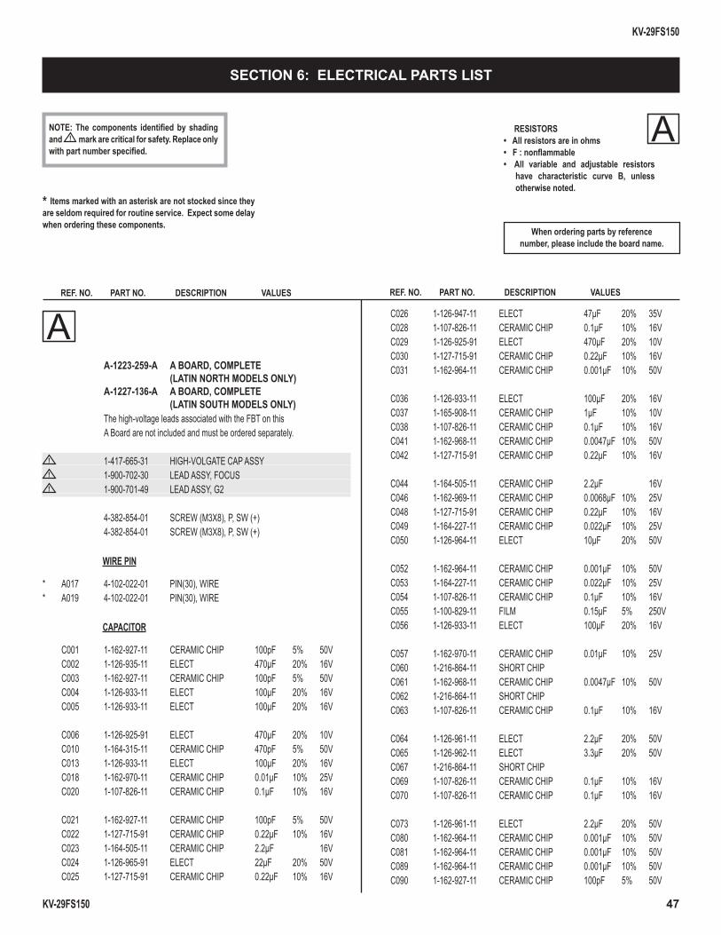
KV-29FS150
KV-29FS150 47
* Items marked with an asterisk are not stocked since they are seldom required for routine service. Expect some delay when ordering these components.
RESISTORS• All resistors are in ohms• F : nonfl ammable• All variable and adjustable resistors
have characteristic curve B, unless otherwise noted.
REF. NO. PART NO. DESCRIPTION VALUES
When ordering parts by referencenumber, please include the board name.
A
REF. NO. PART NO. DESCRIPTION VALUES
NOTE: The components identifi ed by shading and ! mark are critical for safety. Replace only with part number specifi ed.
SECTION 6: ELECTRICAL PARTS LIST
A A-1223-259-A A BOARD, COMPLETE (LATIN NORTH MODELS ONLY) A-1227-136-A A BOARD, COMPLETE (LATIN SOUTH MODELS ONLY) The high-voltage leads associated with the FBT on this A Board are not included and must be ordered separately.
! 1-417-665-31 HIGH-VOLGATE CAP ASSY! 1-900-702-30 LEAD ASSY, FOCUS! 1-900-701-49 LEAD ASSY, G2
4-382-854-01 SCREW (M3X8), P, SW (+) 4-382-854-01 SCREW (M3X8), P, SW (+)
WIRE PIN
* A017 4-102-022-01 PIN(30), WIRE* A019 4-102-022-01 PIN(30), WIRE
CAPACITOR
C001 1-162-927-11 CERAMIC CHIP 100pF 5% 50V C002 1-126-935-11 ELECT 470µF 20% 16V C003 1-162-927-11 CERAMIC CHIP 100pF 5% 50V C004 1-126-933-11 ELECT 100µF 20% 16V C005 1-126-933-11 ELECT 100µF 20% 16V
C006 1-126-925-91 ELECT 470µF 20% 10V C010 1-164-315-11 CERAMIC CHIP 470pF 5% 50V C013 1-126-933-11 ELECT 100µF 20% 16V C018 1-162-970-11 CERAMIC CHIP 0.01µF 10% 25V C020 1-107-826-11 CERAMIC CHIP 0.1µF 10% 16V
C021 1-162-927-11 CERAMIC CHIP 100pF 5% 50V C022 1-127-715-91 CERAMIC CHIP 0.22µF 10% 16V C023 1-164-505-11 CERAMIC CHIP 2.2µF 16V C024 1-126-965-91 ELECT 22µF 20% 50V C025 1-127-715-91 CERAMIC CHIP 0.22µF 10% 16V
C026 1-126-947-11 ELECT 47µF 20% 35V C028 1-107-826-11 CERAMIC CHIP 0.1µF 10% 16V C029 1-126-925-91 ELECT 470µF 20% 10V C030 1-127-715-91 CERAMIC CHIP 0.22µF 10% 16V C031 1-162-964-11 CERAMIC CHIP 0.001µF 10% 50V
C036 1-126-933-11 ELECT 100µF 20% 16V C037 1-165-908-11 CERAMIC CHIP 1µF 10% 10V C038 1-107-826-11 CERAMIC CHIP 0.1µF 10% 16V C041 1-162-968-11 CERAMIC CHIP 0.0047µF 10% 50V C042 1-127-715-91 CERAMIC CHIP 0.22µF 10% 16V
C044 1-164-505-11 CERAMIC CHIP 2.2µF 16V C046 1-162-969-11 CERAMIC CHIP 0.0068µF 10% 25V C048 1-127-715-91 CERAMIC CHIP 0.22µF 10% 16V C049 1-164-227-11 CERAMIC CHIP 0.022µF 10% 25V C050 1-126-964-11 ELECT 10µF 20% 50V
C052 1-162-964-11 CERAMIC CHIP 0.001µF 10% 50V C053 1-164-227-11 CERAMIC CHIP 0.022µF 10% 25V C054 1-107-826-11 CERAMIC CHIP 0.1µF 10% 16V C055 1-100-829-11 FILM 0.15µF 5% 250V C056 1-126-933-11 ELECT 100µF 20% 16V
C057 1-162-970-11 CERAMIC CHIP 0.01µF 10% 25V C060 1-216-864-11 SHORT CHIP C061 1-162-968-11 CERAMIC CHIP 0.0047µF 10% 50V C062 1-216-864-11 SHORT CHIP C063 1-107-826-11 CERAMIC CHIP 0.1µF 10% 16V
C064 1-126-961-11 ELECT 2.2µF 20% 50V C065 1-126-962-11 ELECT 3.3µF 20% 50V C067 1-216-864-11 SHORT CHIP C069 1-107-826-11 CERAMIC CHIP 0.1µF 10% 16V C070 1-107-826-11 CERAMIC CHIP 0.1µF 10% 16V
C073 1-126-961-11 ELECT 2.2µF 20% 50V C080 1-162-964-11 CERAMIC CHIP 0.001µF 10% 50V C081 1-162-964-11 CERAMIC CHIP 0.001µF 10% 50V C089 1-162-964-11 CERAMIC CHIP 0.001µF 10% 50V C090 1-162-927-11 CERAMIC CHIP 100pF 5% 50V

KV-29FS150
KV-29FS150 48
REF. NO. PART NO. DESCRIPTION VALUES REF. NO. PART NO. DESCRIPTION VALUES
A C091 1-162-927-11 CERAMIC CHIP 100pF 5% 50V C092 1-107-826-11 CERAMIC CHIP 0.1µF 10% 16V C093 1-107-826-11 CERAMIC CHIP 0.1µF 10% 16V C094 1-107-826-11 CERAMIC CHIP 0.1µF 10% 16V C095 1-107-826-11 CERAMIC CHIP 0.1µF 10% 16V
C096 1-107-826-11 CERAMIC CHIP 0.1µF 10% 16V C101 1-126-964-11 ELECT 10µF 20% 50V C102 1-162-915-11 CERAMIC CHIP 10pF 0.50pF 50V C104 1-162-915-11 CERAMIC CHIP 10pF 0.50pF 50V C106 1-126-964-11 ELECT 10µF 20% 50V
C107 1-126-935-11 ELECT 470µF 20% 16V C108 1-126-935-11 ELECT 470µF 20% 16V C109 1-162-968-11 CERAMIC CHIP 0.0047µF 10% 50V C111 1-162-970-11 CERAMIC CHIP 0.01µF 10% 25V C112 1-162-910-11 CERAMIC CHIP 5pF 0.25pF 50V
C115 1-162-970-11 CERAMIC CHIP 0.01µF 10% 25V C116 1-162-968-11 CERAMIC CHIP 0.0047µF 10% 50V C117 1-162-970-11 CERAMIC CHIP 0.01µF 10% 25V C118 1-126-965-91 ELECT 22µF 20% 50V C119 1-163-021-91 CERAMIC CHIP 0.01µF 10% 50V
C120 1-126-935-11 ELECT 470µF 20% 16V C131 1-162-970-11 CERAMIC CHIP 0.01µF 10% 25V C133 1-162-927-11 CERAMIC CHIP 100pF 5% 50V C135 1-162-970-11 CERAMIC CHIP 0.01µF 10% 25V C137 1-162-923-11 CERAMIC CHIP 47pF 5% 50V
C138 1-162-970-11 CERAMIC CHIP 0.01µF 10% 25V C140 1-162-964-11 CERAMIC CHIP 0.001µF 10% 50V C142 1-162-923-11 CERAMIC CHIP 47pF 5% 50V C148 1-100-566-91 CERAMIC CHIP 0.1µF 10% 25V C202 1-165-176-11 CERAMIC CHIP 0.047µF 10% 16V
C203 1-165-176-11 CERAMIC CHIP 0.047µF 10% 16V C204 1-136-497-81 FILM 0.1µF 5% 50V C205 1-126-959-11 ELECT 0.47µF 20% 50V C206 1-162-969-11 CERAMIC CHIP 0.0068µF 10% 25V C207 1-136-497-81 FILM 0.1µF 5% 50V
C208 1-162-969-11 CERAMIC CHIP 0.0068µF 10% 25V C209 1-126-959-11 ELECT 0.47µF 20% 50V C210 1-126-968-11 ELECT 100µF 20% 50V C211 1-126-960-11 ELECT 1µF 20% 50V C213 1-115-339-11 CERAMIC CHIP 0.1µF 10% 50V
C214 1-126-942-61 ELECT 1000µF 20% 25V C215 1-128-550-11 ELECT 2200µF 20% 50V C217 1-126-942-61 ELECT 1000µF 20% 25V C219 1-126-942-61 ELECT 1000µF 20% 25V C231 1-137-374-11 MYLAR 0.047µF 5% 50V
C232 1-137-374-11 MYLAR 0.047µF 5% 50V C234 1-164-315-11 CERAMIC CHIP 470pF 5% 50V C235 1-164-315-11 CERAMIC CHIP 470pF 5% 50V C238 1-126-964-11 ELECT 10µF 20% 50V C239 1-102-228-00 CERAMIC 470pF 10% 500V
C243 1-126-972-11 ELECT 1000µF 20% 50V C244 1-126-972-11 ELECT 1000µF 20% 50V C247 1-100-566-91 CERAMIC CHIP 0.1µF 10% 25V C248 1-100-566-91 CERAMIC CHIP 0.1µF 10% 25V C300 1-127-715-91 CERAMIC CHIP 0.22µF 10% 16V
C301 1-164-315-11 CERAMIC CHIP 470pF 5% 50V C302 1-126-963-11 ELECT 4.7µF 20% 50V C303 1-126-933-11 ELECT 100µF 20% 16V C304 1-126-933-11 ELECT 100µF 20% 16V C308 1-162-970-11 CERAMIC CHIP 0.01µF 10% 25V
C311 1-126-961-11 ELECT 2.2µF 20% 50V C312 1-162-964-11 CERAMIC CHIP 0.001µF 10% 50V C313 1-162-964-11 CERAMIC CHIP 0.001µF 10% 50V C316 1-125-891-11 CERAMIC CHIP 0.47µF 10% 10V C317 1-126-934-11 ELECT 220µF 20% 16V
C318 1-107-826-11 CERAMIC CHIP 0.1µF 10% 16V C319 1-162-923-11 CERAMIC CHIP 47pF 5% 50V C320 1-162-923-11 CERAMIC CHIP 47pF 5% 50V C321 1-127-715-91 CERAMIC CHIP 0.22µF 10% 16V C322 1-162-964-11 CERAMIC CHIP 0.001µF 10% 50V
C323 1-112-034-91 CERAMIC CHIP 0.01µF 5% 50V C325 1-162-964-11 CERAMIC CHIP 0.001µF 10% 50V C328 1-162-970-11 CERAMIC CHIP 0.01µF 10% 25V C332 1-162-964-11 CERAMIC CHIP 0.001µF 10% 50V C333 1-100-566-91 CERAMIC CHIP 0.1µF 10% 25V
C335 1-127-715-91 CERAMIC CHIP 0.22µF 10% 16V C336 1-107-826-11 CERAMIC CHIP 0.1µF 10% 16V C337 1-107-826-11 CERAMIC CHIP 0.1µF 10% 16V C338 1-107-826-11 CERAMIC CHIP 0.1µF 10% 16V C502 1-126-933-11 ELECT 100µF 20% 16V
C507 1-102-228-00 CERAMIC 470pF 10% 500V C511 1-164-690-91 CERAMIC CHIP 0.0022µF 5% 50V C513 1-162-970-11 CERAMIC CHIP 0.01µF 10% 25V C514 1-106-383-00 MYLAR 0.047µF 10% 200V C517 1-162-970-11 CERAMIC CHIP 0.01µF 10% 25V
C518 1-162-923-11 CERAMIC CHIP 47pF 5% 50V C519 1-164-645-11 CERAMIC 1000pF 10% 500V C521 1-126-933-11 ELECT 100µF 20% 16V C523 1-164-645-11 CERAMIC 1000pF 10% 500V C524 1-162-923-11 CERAMIC CHIP 47pF 5% 50V

KV-29FS150
KV-29FS150 49
REF. NO. PART NO. DESCRIPTION VALUES REF. NO. PART NO. DESCRIPTION VALUES
NOTE: The components identifi ed by shading and ! mark are critical for safety. Replace only with part number specifi ed.
C527 1-162-970-11 CERAMIC CHIP 0.01µF 10% 25V C537 1-107-911-11 ELECT 220µF 20% 50V
! C538 1-117-651-11 FILM 20000pF 3% 1.2KV! C539 1-130-895-00 FILM 0.056µF 5% 400V
C540 1-136-171-00 FILM 0.33µF 5% 50V
C550 1-106-220-00 MYLAR 0.1µF 10% 100V C556 1-126-941-11 ELECT 470µF 20% 25V C557 1-126-941-11 ELECT 470µF 20% 25V C558 1-123-024-21 ELECT 33µF 160V C565 1-107-645-11 ELECT 22µF 20% 200V
! C567 1-117-813-91 FILM 0.75µF 5% 250V! C570 1-115-521-11 FILM 0.82µF 5% 250V
C572 1-117-661-71 FILM 0.15µF 5% 250V C574 1-107-683-11 ELECT 2.2µF 250V C577 1-106-383-00 MYLAR 0.047µF 5% 200V
C580 1-126-933-11 ELECT 100µF 20% 16V C587 1-115-339-11 CERAMIC CHIP 0.1µF 10% 50V C588 1-162-964-11 CERAMIC CHIP 0.001µF 10% 50V C590 1-162-968-11 CERAMIC CHIP 0.0047µF 10% 50V C592 1-164-315-11 CERAMIC CHIP 470pF 5% 50V
C597 1-126-925-91 ELECT 470µF 20% 10V C598 1-162-968-11 CERAMIC CHIP 0.0047µF 10% 50V C603 1-136-497-81 FILM 0.1µF 5% 50V C604 1-126-962-11 ELECT 3.3µF 20% 50V (LATIN NORTH MODELS ONLY) C604 1-126-961-11 ELECT 2.2µF 20% 50V (LATIN SOUTH MODELS ONLY) C605 1-161-830-00 CERAMIC 0.0047µF 99% 500V
C606 1-161-830-00 CERAMIC 0.0047µF 99% 500V C609 1-161-830-00 CERAMIC 0.0047µF 99% 500V C610 1-161-830-00 CERAMIC 0.0047µF 99% 500V C611 1-117-752-11 ELECT(BLOCK) 330µF 20% 450V (LATIN SOUTH MODELS ONLY)
C616 1-164-315-11 CERAMIC CHIP 470pF 5% 50V C623 1-162-966-11 CERAMIC CHIP 0.0022µF 10% 50V
C624 1-126-965-91 ELECT 22µF 20% 50V! C625 1-127-942-51 CERAMIC 330pF 10% 250V
C626 1-104-330-91 CERAMIC 470pF 10% 1KV C628 1-104-331-11 CERAMIC 0.0022µF 10% 1KV C630 1-128-549-11 ELECT 3300µF 20% 35V
C632 1-126-953-11 ELECT 2200µF 20% 35V C634 1-126-941-11 ELECT 470µF 20% 25V C635 1-126-971-11 ELECT 470µF 20% 50V C637 1-107-882-91 ELECT 100µF 20% 16V C638 1-107-882-91 ELECT 100µF 20% 16V
C639 1-126-933-11 ELECT 100µF 20% 16V C641 1-107-882-91 ELECT 100µF 20% 16V C643 1-117-720-11 CERAMIC CHIP 4.7µF 10V C647 1-126-935-11 ELECT 470µF 20% 16V C649 1-126-933-11 ELECT 100µF 20% 16V
C653 1-102-228-00 CERAMIC 470pF 10% 500V C654 1-104-330-91 CERAMIC 470pF 10% 1KV
! C657 1-113-889-11 CERAMIC 0.001µF 20% 250V C658 1-100-957-11 ELECT(BLOCK) 820µF 20% 250V (LATIN NORTH MODELS ONLY)
! C660 1-165-539-31 FILM 0.22µF 10% 275V
C662 1-107-826-11 CERAMIC CHIP 0.1µF 10% 16V C665 1-107-855-12 ELECT(BLOCK) 330µF 160V
! C666 1-165-538-31 FILM 0.1µF 10% 275V C668 1-126-933-11 ELECT 100µF 20% 16V C672 1-162-970-11 CERAMIC CHIP 0.01µF 10% 25V
C678 1-164-505-11 CERAMIC CHIP 2.2µF 16V C680 1-164-315-11 CERAMIC CHIP 470pF 5% 50V C682 1-126-943-11 ELECT 2200µF 20% 25V C685 1-126-934-11 ELECT 220µF 20% 16V C686 1-117-720-11 CERAMIC CHIP 4.7µF 10V
! C687 1-113-889-11 CERAMIC 0.001µF 20% 250V C691 1-104-331-11 CERAMIC 0.0022µF 10% 1KV (LATIN NORTH MODELS ONLY) C691 1-117-214-11 CERAMIC 0.001µF 10% 2KV (LATIN SOUTH MODELS ONLY)
! C693 1-127-942-51 CERAMIC 330pF 10% 250V C694 1-100-761-21 CERAMIC CHIP 0.01µF 10% 250V C900 1-164-505-11 CERAMIC CHIP 2.2µF 16V
C901 1-164-505-11 CERAMIC CHIP 2.2µF 16V C902 1-216-864-11 SHORT CHIP C903 1-126-935-11 ELECT 470µF 20% 16V C905 1-162-970-11 CERAMIC CHIP 0.01µF 10% 25V C906 1-164-346-11 CERAMIC CHIP 1µF 16V
C907 1-164-346-11 CERAMIC CHIP 1µF 16V C908 1-164-346-11 CERAMIC CHIP 1µF 16V C909 1-164-346-11 CERAMIC CHIP 1µF 16V C910 1-164-315-11 CERAMIC CHIP 470pF 5% 50V C911 1-164-315-11 CERAMIC CHIP 470pF 5% 50V
C912 1-164-315-11 CERAMIC CHIP 470pF 5% 50V C913 1-164-315-11 CERAMIC CHIP 470pF 5% 50V C914 1-164-315-11 CERAMIC CHIP 470pF 5% 50V C915 1-164-315-11 CERAMIC CHIP 470pF 5% 50V C916 1-164-004-11 CERAMIC CHIP 0.1µF 10% 25V
A

KV-29FS150
KV-29FS150 50
REF. NO. PART NO. DESCRIPTION VALUES REF. NO. PART NO. DESCRIPTION VALUES
NOTE: The components identifi ed by shading and ! mark are critical for safety. Replace only with part number specifi ed.
C922 1-164-315-11 CERAMIC CHIP 470pF 5% 50V C925 1-164-315-11 CERAMIC CHIP 470pF 5% 50V C956 1-126-933-11 ELECT 100µF 20% 16V C967 1-164-505-11 CERAMIC CHIP 2.2µF 16V C980 1-126-965-91 ELECT 22µF 20% 50V
C981 1-216-864-11 SHORT CHIP C983 1-216-864-11 SHORT CHIP C1019 1-125-891-11 CERAMIC CHIP 0.47µF 10% 10V C5001 1-107-957-11 ELECT 1µF 20% 250V C5073 1-106-375-12 MYLAR 0.022µF 5% 200V
CONNECTOR
* CN507 1-564-509-11 PLUG, CONNECTOR 6P* CN600 1-508-786-00 PIN, CONNECTOR (5MM PITCH) 2P* CN601 1-691-134-11 PIN, CONNECTOR (PC BOARD) 2P (LATIN SOUTH MODELS ONLY)* CN602 1-573-963-11 PIN, CONNECTOR (PC BOARD) (LATIN NORTH MODELS ONLY)
* CN904 1-508-743-00 PIN, CONNECTOR 5P* CN2105 1-564-507-11 PLUG, CONNECTOR 4P* CN3102 1-564-510-11 PLUG, CONNECTOR 7P
! CN6101 1-580-843-11 PIN, CONNECTOR (POWER)* CN9201 1-564-508-11 PLUG, CONNECTOR 5P
DIODE
D002 8-719-404-50 DIODE MA111-TX D003 8-719-404-50 DIODE MA111-TX D023 8-719-069-60 DIODE UDZSTE-179.1B D024 8-719-069-60 DIODE UDZSTE-179.1B D025 8-719-069-60 DIODE UDZSTE-179.1B
D057 8-719-404-50 DIODE MA111-TX D058 8-719-404-50 DIODE MA111-TX D059 8-719-404-50 DIODE MA111-TX D064 8-719-977-03 DIODE DTZ5.6B D065 8-719-977-03 DIODE DTZ5.6B
D066 8-719-083-20 DIODE PG102R D068 8-719-977-03 DIODE DTZ5.6B D074 8-719-991-33 DIODE 1SS133T-77 D075 8-719-422-97 DIODE MA8091-M D082 6-500-600-01 DIODE MM3Z3V3T1
D083 6-500-600-01 DIODE MM3Z3V3T1 D084 6-500-600-01 DIODE MM3Z3V3T1 D103 8-719-036-43 DIODE MA4300-H(TA) D105 8-719-404-50 DIODE MA111-TX D106 6-500-600-01 DIODE MM3Z3V3T1
D108 8-719-036-94 DIODE RD5.6SB-T1 D109 8-719-036-94 DIODE RD5.6SB-T1 D200 8-719-062-51 DIODE 1PS226-115 D201 8-719-404-50 DIODE MA111-TX D202 8-719-404-50 DIODE MA111-TX
D203 8-719-404-50 DIODE MA111-TX D204 8-719-404-50 DIODE MA111-TX D205 8-719-404-50 DIODE MA111-TX D208 8-719-404-50 DIODE MA111-TX D212 8-719-404-50 DIODE MA111-TX
D213 8-719-404-50 DIODE MA111-TX D214 8-719-404-50 DIODE MA111-TX D218 8-719-991-33 DIODE 1SS133T-77 D219 8-719-991-33 DIODE 1SS133T-77 D220 8-719-036-51 DIODE MA4360-H(TA)
D221 8-719-036-51 DIODE MA4360-H(TA) D222 8-719-080-57 DIODE FSF05A20 D501 8-719-404-50 DIODE MA111-TX D504 8-719-074-25 DIODE PG104R D505 8-719-404-50 DIODE MA111-TX
D506 8-719-404-50 DIODE MA111-TX D507 8-719-978-33 DIODE DTZ-TT11-6.8B D508 8-719-404-50 DIODE MA111-TX D509 8-719-422-97 DIODE MA8091-M D511 8-719-404-50 DIODE MA111-TX
D513 8-719-075-05 DIODE FR104-A5 D517 6-501-299-01 DIODE BY228GP D518 8-719-312-10 DIODE RU4AM-T3 D521 8-719-085-57 DIODE ER202 D522 8-719-085-57 DIODE ER202
D523 8-719-074-25 DIODE PG104R D527 8-719-075-05 DIODE FR104-A5 D528 8-719-075-05 DIODE FR104-A5 D529 8-719-991-33 DIODE 1SS133T-77 D530 8-719-036-37 DIODE MA4270-L(TA)
D536 8-719-404-50 DIODE MA111-TX D537 8-719-404-50 DIODE MA111-TX D548 8-719-991-33 DIODE 1SS133T-77 D549 8-719-036-94 DIODE RD5.6SB-T1 D550 8-719-036-43 DIODE MA4300-H(TA)
D600 8-719-404-50 DIODE MA111-TX D602 6-501-301-01 DIODE 1A5G D603 6-501-301-01 DIODE 1A5G D604 8-719-077-77 DIODE D3SB60F3 D606 8-719-109-97 DIODE RD6.8ESB2
A

KV-29FS150
KV-29FS150 51
REF. NO. PART NO. DESCRIPTION VALUES REF. NO. PART NO. DESCRIPTION VALUES D614 8-719-036-41 DIODE MA4300-L(TA) (LATIN SOUTH MODELS ONLY) D615 6-500-175-01 DIODE 1E3-TB (LATIN SOUTH MODELS ONLY)
D617 6-500-175-01 DIODE 1E3-TB D618 6-500-175-01 DIODE 1E3-TB D619 6-500-175-01 DIODE 1E3-TB D621 8-719-312-10 DIODE RU4AM-T3 D622 6-500-175-01 DIODE 1E3-TB
D625 8-719-510-73 DIODE S3L20µF4 D629 8-719-035-55 DIODE MA4039-H(TA) D635 6-501-588-01 DIODE MA8036-H-TX D636 8-719-036-43 DIODE MA4300-H(TA) D637 8-719-072-70 DIODE MA2ZD14001S0
D638 8-719-404-50 DIODE MA111-TX D639 6-501-311-01 DIODE SB360-S D642 8-719-422-97 DIODE MA8091-M D643 8-719-017-79 DIODE MA8033 D645 8-719-057-76 DIODE MA8150-M-TX
D646 8-719-057-76 DIODE MA8150-M-TX D647 8-719-017-79 DIODE MA8033 D648 8-719-422-97 DIODE MA8091-M D649 8-719-057-76 DIODE MA8150-M-TX D650 8-719-422-97 DIODE MA8091-M
D651 8-719-422-97 DIODE MA8091-M D652 8-719-017-67 DIODE MA8068-H D653 8-719-017-67 DIODE MA8068-H D900 8-719-422-97 DIODE MA8091-M D908 8-719-977-03 DIODE DTZ5.6B
D909 8-719-977-03 DIODE DTZ5.6B D910 8-719-977-03 DIODE DTZ5.6B
DY CONNECTOR
* DY1 1-580-798-11 CONNECTOR PIN (DY) 6P
FERRITE BEAD
FB005 1-469-981-21 FERRITE 0µH FB006 1-469-981-21 FERRITE 0µH FB007 1-469-981-21 FERRITE 0µH FB008 1-469-981-21 FERRITE 0µH FB009 1-414-229-11 FERRITE 0µH
FB010 1-216-864-11 SHORT CHIP FB011 1-414-234-22 FERRITE 0µH FB201 1-469-578-11 FERRITE 1.1µH FB503 1-469-579-11 FERRITE 0.45µH FB504 1-469-578-11 FERRITE 1.1µH
FB601 1-469-578-11 FERRITE 1.1µH FB603 1-469-578-11 FERRITE 1.1µH FB605 1-469-578-11 FERRITE 1.1µH FB608 1-412-911-31 FERRITE 0µH FB610 1-469-578-11 FERRITE 1.1µH
IC
IC001 6-709-776-01 IC TDA12001H/N1F4B IC003 6-710-021-01 IC CAT24C16WI-GT3 IC200 6-703-477-01 IC AN5277T IC502 8-759-700-07 IC NJM2903M IC503 6-709-348-01 IC LA78041-E
IC601 6-709-448-01 IC STR-W6735-LF2011 (LATIN NORTH MODELS ONLY) IC601 6-709-487-01 IC STR-W6753-LF2011 (LATIN SOUTH MODELS ONLY) IC602 6-706-789-01 IC KIA78R09API IC603 6-703-478-01 IC PQ018EF01SSH IC604 8-759-646-52 IC KIA7805API IC605 6-705-063-01 IC SE135N-LF38
IC606 6-706-886-01 IC KIA78D33PI IC607 8-759-832-05 IC BA18BC0FP-E2
JACK
J900 1-694-242-11 TERMINAL, S J901 1-817-299-22 PHONO JACK 11P
CHIP CONDUCTOR
JR003 1-216-864-11 SHORT CHIP JR007 1-216-864-11 SHORT CHIP JR008 1-216-864-11 SHORT CHIP JR009 1-216-864-11 SHORT CHIP JR013 1-216-864-11 SHORT CHIP
JR014 1-216-864-11 SHORT CHIP JR016 1-216-864-11 SHORT CHIP JR026 1-216-864-11 SHORT CHIP JR027 1-216-864-11 SHORT CHIP JR030 1-216-864-11 SHORT CHIP
JR036 1-216-864-11 SHORT CHIP JR037 1-216-864-11 SHORT CHIP JR042 1-216-797-11 METAL CHIP 10 5% 1/10W JR049 1-216-864-11 SHORT CHIP JR051 1-216-864-11 SHORT CHIP
JR052 1-216-864-11 SHORT CHIP JR071 1-216-864-11 SHORT CHIP JR072 1-216-864-11 SHORT CHIP JR099 1-216-864-11 SHORT CHIP JR203 1-216-864-11 SHORT CHIP
A

KV-29FS150
KV-29FS150 52
REF. NO. PART NO. DESCRIPTION VALUES REF. NO. PART NO. DESCRIPTION VALUES
NOTE: The components identifi ed by shading and ! mark are critical for safety. Replace only with part number specifi ed.
JR204 1-216-864-11 SHORT CHIP JR205 1-216-864-11 SHORT CHIP JR301 1-216-864-11 SHORT CHIP JR302 1-216-864-11 SHORT CHIP JR303 1-216-864-11 SHORT CHIP
JR304 1-216-864-11 SHORT CHIP JR305 1-216-864-11 SHORT CHIP JR306 1-216-864-11 SHORT CHIP JR501 1-216-864-11 SHORT CHIP JR502 1-216-864-11 SHORT CHIP
JR503 1-216-864-11 SHORT CHIP JR504 1-216-864-11 SHORT CHIP JR506 1-216-864-11 SHORT CHIP JR509 1-216-864-11 SHORT CHIP JR511 1-216-864-11 SHORT CHIP
JR512 1-216-864-11 SHORT CHIP JR513 1-216-864-11 SHORT CHIP JR522 1-216-864-11 SHORT CHIP JR601 1-216-864-11 SHORT CHIP JR602 1-216-864-11 SHORT CHIP
JR650 1-216-864-11 SHORT CHIP JR651 1-216-864-11 SHORT CHIP JR652 1-216-864-11 SHORT CHIP JR653 1-216-864-11 SHORT CHIP JR654 1-216-864-11 SHORT CHIP
JR655 1-216-864-11 SHORT CHIP JR666 1-216-864-11 SHORT CHIP JR667 1-216-864-11 SHORT CHIP JR668 1-216-864-11 SHORT CHIP JR800 1-216-864-11 SHORT CHIP
JR801 1-216-864-11 SHORT CHIP JR805 1-216-864-11 SHORT CHIP JR901 1-216-864-11 SHORT CHIP JR902 1-216-864-11 SHORT CHIP JR1006 1-216-864-11 SHORT CHIP
JR1011 1-216-864-11 SHORT CHIP JR1012 1-216-864-11 SHORT CHIP JR1050 1-216-811-11 METAL CHIP 150 5% 1/10W JR1100 1-216-864-11 SHORT CHIP JR1101 1-216-864-11 SHORT CHIP
JR1110 1-216-864-11 SHORT CHIP JR1111 1-216-864-11 SHORT CHIP JR1903 1-216-864-11 SHORT CHIP JR2108 1-216-864-11 SHORT CHIP JR2109 1-216-864-11 SHORT CHIP
JR2110 1-216-864-11 SHORT CHIP JR5001 1-216-864-11 SHORT CHIP JR5035 1-216-864-11 SHORT CHIP
COIL
L003 1-414-856-11 INDUCTOR 10µH L004 1-414-187-11 INDUCTOR 47µH L005 1-414-856-11 INDUCTOR 10µH L006 1-414-856-11 INDUCTOR 10µH L007 1-414-856-11 INDUCTOR 10µH
L008 1-414-856-11 INDUCTOR 10µH L009 1-414-934-21 INDUCTOR 10µH L010 1-414-934-21 INDUCTOR 10µH L011 1-414-934-21 INDUCTOR 10µH L012 1-414-934-21 INDUCTOR 10µH
L013 1-414-934-21 INDUCTOR 10µH L031 1-414-856-11 INDUCTOR 10µH L032 1-414-856-11 INDUCTOR 10µH L033 1-414-934-21 INDUCTOR 10µH L035 1-414-856-11 INDUCTOR 10µH
L036 1-414-934-21 INDUCTOR 10µH L100 1-414-857-11 INDUCTOR 100µH L101 1-414-138-11 INDUCTOR 0.33µH L106 1-414-189-31 INDUCTOR 100µH L201 1-412-519-11 INDUCTOR 3.3µH
L507 1-419-633-21 INDUCTOR 10MH L512 1-406-666-21 INDUCTOR 150µH L513 1-412-552-11 INDUCTOR 2.2MH L514 1-408-947-00 INDUCTOR 2.2MH L515 1-406-677-11 INDUCTOR 10MH
L600 1-412-529-11 INDUCTOR 22µH L601 1-412-533-21 INDUCTOR 47µH L602 1-412-529-11 INDUCTOR 22µH L902 1-414-187-11 INDUCTOR 47µH L2601 1-406-659-11 INDUCTOR 10µH
PHOTO COUPLER
! PH600 8-749-019-60 IC K1010HB01
IC LINK
! PS201 1-533-597-41 IC LINK 5A 90V! PS602 1-533-597-41 IC LINK 5A 90V! PS603 1-533-597-41 IC LINK 5A 90V
PS604 1-533-597-41 IC LINK 5A 90V PS605 1-533-597-41 IC LINK 5A 90V
A

KV-29FS150
KV-29FS150 53
REF. NO. PART NO. DESCRIPTION VALUES REF. NO. PART NO. DESCRIPTION VALUES TRANSISTOR
Q001 8-729-038-67 TRANSISTOR KRC102S Q010 8-729-600-22 TRANSISTOR 2SA1235-F Q016 8-729-038-67 TRANSISTOR KRC102S Q018 8-729-038-67 TRANSISTOR KRC102S Q100 8-729-120-28 TRANSISTOR 2SC1623-L5L6
Q102 8-729-022-54 TRANSISTOR 2SC3779C,D-AA Q111 8-729-120-28 TRANSISTOR 2SC1623-L5L6 Q200 8-729-038-67 TRANSISTOR KRC102S Q201 8-729-600-22 TRANSISTOR 2SA1235-F Q202 8-729-600-22 TRANSISTOR 2SA1235-F
Q206 8-729-038-67 TRANSISTOR KRC102S Q501 6-550-362-01 TRANSISTOR KTA1279 Q502 8-729-140-50 TRANSISTOR 2SC3209LK Q503 8-729-120-28 TRANSISTOR 2SC1623-L5L6 Q505 6-551-406-01 TRANSISTOR IRFS614BYDTU
Q506 6-551-129-01 TRANSISTOR 2SK3462 Q511 6-550-845-01 TRANSISTOR TT2142 Q512 8-729-120-28 TRANSISTOR 2SC1623-L5L6 Q513 8-729-600-22 TRANSISTOR 2SA1235-F Q515 8-729-120-28 TRANSISTOR 2SC1623-L5L6
Q516 6-550-362-01 TRANSISTOR KTA1279 Q601 8-729-120-28 TRANSISTOR 2SC1623-L5L6 Q608 8-729-120-28 TRANSISTOR 2SC1623-L5L6 Q609 8-729-120-28 TRANSISTOR 2SC1623-L5L6 Q900 8-729-600-22 TRANSISTOR 2SA1235-F
Q901 8-729-027-56 TRANSISTOR DTC143TKA-T146 Q902 8-729-027-56 TRANSISTOR DTC143TKA-T146
RESISTOR
R001 1-216-829-11 METAL CHIP 4.7K 5% 1/10W R002 1-216-809-11 METAL CHIP 100 5% 1/10W R003 1-216-829-11 METAL CHIP 4.7K 5% 1/10W R004 1-216-809-11 METAL CHIP 100 5% 1/10W R010 1-216-833-11 METAL CHIP 10K 5% 1/10W
R011 1-216-817-11 METAL CHIP 470 5% 1/10W R012 1-216-825-11 METAL CHIP 2.2K 5% 1/10W R014 1-216-809-11 METAL CHIP 100 5% 1/10W R015 1-216-823-11 METAL CHIP 1.5K 5% 1/10W R020 1-216-809-11 METAL CHIP 100 5% 1/10W
R022 1-216-809-11 METAL CHIP 100 5% 1/10W R023 1-216-829-11 METAL CHIP 4.7K 5% 1/10W R024 1-216-809-11 METAL CHIP 100 5% 1/10W R025 1-216-809-11 METAL CHIP 100 5% 1/10W R026 1-216-809-11 METAL CHIP 100 5% 1/10W
R029 1-216-809-11 METAL CHIP 100 5% 1/10W R030 1-216-809-11 METAL CHIP 100 5% 1/10W R038 1-216-809-11 METAL CHIP 100 5% 1/10W R039 1-216-809-11 METAL CHIP 100 5% 1/10W R041 1-216-809-11 METAL CHIP 100 5% 1/10W
R042 1-216-825-11 METAL CHIP 2.2K 5% 1/10W R044 1-216-834-11 METAL CHIP 12K 5% 1/10W R045 1-216-809-11 METAL CHIP 100 5% 1/10W R046 1-216-809-11 METAL CHIP 100 5% 1/10W R048 1-216-809-11 METAL CHIP 100 5% 1/10W
R051 1-218-885-11 METAL CHIP 39K 0.50% 1/10W R056 1-216-825-11 METAL CHIP 2.2K 5% 1/10W R058 1-216-864-11 SHORT CHIP R059 1-216-821-11 METAL CHIP 1K 5% 1/10W R060 1-216-809-11 METAL CHIP 100 5% 1/10W
R061 1-216-819-11 METAL CHIP 680 5% 1/10W R088 1-216-816-11 METAL CHIP 390 5% 1/10W R096 1-216-813-11 METAL CHIP 220 5% 1/10W R097 1-216-813-11 METAL CHIP 220 5% 1/10W R099 1-216-813-11 METAL CHIP 220 5% 1/10W
R100 1-216-821-11 METAL CHIP 1K 5% 1/10W R103 1-211-981-11 METAL CHIP 33 0.50% 1/10W R106 1-216-832-11 METAL CHIP 8.2K 5% 1/10W R107 1-216-826-11 METAL CHIP 2.7K 5% 1/10W R108 1-216-820-11 METAL CHIP 820 5% 1/10W
R109 1-216-021-00 RES-CHIP 68 5% 1/10W R115 1-216-809-11 METAL CHIP 100 5% 1/10W R116 1-216-809-11 METAL CHIP 100 5% 1/10W R118 1-216-809-11 METAL CHIP 100 5% 1/10W R119 1-211-981-11 METAL CHIP 33 0.50% 1/10W
R121 1-215-925-11 METAL OXIDE 22K 5% 3W R128 1-216-864-11 SHORT CHIP R146 1-216-821-11 METAL CHIP 1K 5% 1/10W R147 1-216-813-11 METAL CHIP 220 5% 1/10W R148 1-211-969-11 METAL CHIP 10 0.50% 1/10W
R149 1-216-823-11 METAL CHIP 1.5K 5% 1/10W R150 1-216-809-11 METAL CHIP 100 5% 1/10W R152 1-216-811-11 METAL CHIP 150 5% 1/10W R153 1-218-839-11 METAL CHIP 470 0.50% 1/10W R156 1-216-864-11 SHORT CHIP
R200 1-216-830-11 METAL CHIP 5.6K 5% 1/10W R201 1-216-827-11 METAL CHIP 3.3K 5% 1/10W R202 1-218-867-11 METAL CHIP 6.8K 0.50% 1/10W R203 1-216-830-11 METAL CHIP 5.6K 5% 1/10W R204 1-216-827-11 METAL CHIP 3.3K 5% 1/10W
A

KV-29FS150
KV-29FS150 54
REF. NO. PART NO. DESCRIPTION VALUES REF. NO. PART NO. DESCRIPTION VALUES R205 1-218-867-11 METAL CHIP 6.8K 0.50% 1/10W R206 1-216-809-11 METAL CHIP 100 5% 1/10W R207 1-218-867-11 METAL CHIP 6.8K 0.50% 1/10W R208 1-218-867-11 METAL CHIP 6.8K 0.50% 1/10W R210 1-216-835-11 METAL CHIP 15K 5% 1/10W
R211 1-216-835-11 METAL CHIP 15K 5% 1/10W R212 1-216-809-11 METAL CHIP 100 5% 1/10W R213 1-216-835-11 METAL CHIP 15K 5% 1/10W R214 1-216-835-11 METAL CHIP 15K 5% 1/10W R215 1-216-833-11 METAL CHIP 10K 5% 1/10W
R216 1-216-833-11 METAL CHIP 10K 5% 1/10W R220 1-216-864-11 SHORT CHIP R221 1-216-809-11 METAL CHIP 100 5% 1/10W R234 1-249-401-11 CARBON 47 5% 1/4W R235 1-249-401-11 CARBON 47 5% 1/4W
R236 1-216-827-11 METAL CHIP 3.3K 5% 1/10W R237 1-216-809-11 METAL CHIP 100 5% 1/10W R238 1-216-809-11 METAL CHIP 100 5% 1/10W R241 1-216-825-11 METAL CHIP 2.2K 5% 1/10W R242 1-216-825-11 METAL CHIP 2.2K 5% 1/10W
R306 1-218-873-11 METAL CHIP 12K 0.50% 1/10W R314 1-216-829-11 METAL CHIP 4.7K 5% 1/10W R315 1-216-829-11 METAL CHIP 4.7K 5% 1/10W R316 1-218-867-11 METAL CHIP 6.8K 0.50% 1/10W R317 1-216-829-11 METAL CHIP 4.7K 5% 1/10W
R320 1-218-863-11 METAL CHIP 4.7K 0.50% 1/10W R323 1-216-809-11 METAL CHIP 100 5% 1/10W R324 1-216-864-11 SHORT CHIP R336 1-216-829-11 METAL CHIP 4.7K 5% 1/10W R337 1-216-817-11 METAL CHIP 470 5% 1/10W
R338 1-216-825-11 METAL CHIP 2.2K 5% 1/10W R339 1-216-809-11 METAL CHIP 100 5% 1/10W R340 1-216-825-11 METAL CHIP 2.2K 5% 1/10W R341 1-216-809-11 METAL CHIP 100 5% 1/10W R355 1-216-837-11 METAL CHIP 22K 5% 1/10W
R356 1-218-851-11 METAL CHIP 1.5K 0.50% 1/10W R364 1-216-817-11 METAL CHIP 470 5% 1/10W R377 1-216-823-11 METAL CHIP 1.5K 5% 1/10W R379 1-216-843-11 METAL CHIP 68K 5% 1/10W R380 1-216-809-11 METAL CHIP 100 5% 1/10W
R384 1-216-809-11 METAL CHIP 100 5% 1/10W R385 1-216-809-11 METAL CHIP 100 5% 1/10W R386 1-216-809-11 METAL CHIP 100 5% 1/10W R387 1-218-285-11 METAL CHIP 75 5% 1/10W R388 1-218-285-11 METAL CHIP 75 5% 1/10W
R389 1-218-285-11 METAL CHIP 75 5% 1/10W R393 1-216-809-11 METAL CHIP 100 5% 1/10W R394 1-216-829-11 METAL CHIP 4.7K 5% 1/10W R395 1-216-845-11 METAL CHIP 100K 5% 1/10W R399 1-216-829-11 METAL CHIP 4.7K 5% 1/10W
R500 1-216-821-11 METAL CHIP 1K 5% 1/10W R501 1-218-867-11 METAL CHIP 6.8K 0.50% 1/10W R502 1-260-127-11 CARBON 220K 5% 1/2W R503 1-216-841-11 METAL CHIP 47K 5% 1/10W R504 1-216-841-11 METAL CHIP 47K 5% 1/10W
R505 1-216-829-11 METAL CHIP 4.7K 5% 1/10W R506 1-216-829-11 METAL CHIP 4.7K 5% 1/10W R510 1-243-527-71 METAL OXIDE 47 5% 3W R513 1-216-849-11 METAL CHIP 220K 5% 1/10W R514 1-216-841-11 METAL CHIP 47K 5% 1/10W
R515 1-216-853-11 METAL CHIP 470K 5% 1/10W R518 1-216-838-11 METAL CHIP 27K 5% 1/10W R519 1-216-841-11 METAL CHIP 47K 5% 1/10W R520 1-218-869-11 METAL CHIP 8.2K 0.50% 1/10W R521 1-216-841-11 METAL CHIP 47K 5% 1/10W
R522 1-249-428-11 CARBON 8.2K 5% 1/4W R523 1-216-839-11 METAL CHIP 33K 5% 1/10W R524 1-218-887-11 METAL CHIP 47K 0.50% 1/10W R525 1-245-476-21 METAL 390K 1% 1/4W R526 1-218-865-11 METAL CHIP 5.6K 0.50% 1/10W
R529 1-218-875-11 METAL CHIP 15K 0.50% 1/10W R530 1-218-879-11 METAL CHIP 22K 0.50% 1/10W R531 1-216-861-11 METAL CHIP 2.2M 5% 1/10W R532 1-216-857-11 METAL CHIP 1M 5% 1/10W R533 1-216-846-11 METAL CHIP 120K 5% 1/10W
R535 1-216-809-11 METAL CHIP 100 5% 1/10W R536 1-218-879-11 METAL CHIP 22K 0.50% 1/10W R537 1-218-867-11 METAL CHIP 6.8K 0.50% 1/10W R538 1-215-451-00 METAL 18K 1% 1/4W R542 1-216-827-11 METAL CHIP 3.3K 5% 1/10W
R543 1-216-437-00 METAL OXIDE 5.6K 5% 1W R544 1-218-891-11 METAL CHIP 68K 0.50% 1/10W R547 1-243-571-71 METAL OXIDE 390 5% 2W R548 1-215-915-21 METAL OXIDE 470 5% 3W R551 1-215-445-00 METAL 10K 1% 1/4W
R553 1-218-845-11 METAL CHIP 820 0.50% 1/10W R554 1-218-863-11 METAL CHIP 4.7K 0.50% 1/10W R555 1-215-873-00 METAL OXIDE 4.7K 5% 1W R556 1-218-871-11 METAL CHIP 10K 0.50% 1/10W R560 1-216-825-11 METAL CHIP 2.2K 5% 1/10W
A

KV-29FS150
KV-29FS150 55
REF. NO. PART NO. DESCRIPTION VALUES REF. NO. PART NO. DESCRIPTION VALUES
NOTE: The components identifi ed by shading and ! mark are critical for safety. Replace only with part number specifi ed.
R562 1-243-683-71 METAL OXIDE 47 5% 1W R568 1-249-383-11 CARBON 1.5 5% 1/4W R571 1-218-865-11 METAL CHIP 5.6K 0.50% 1/10W R577 1-243-565-71 METAL OXIDE 120 5% 2W R578 1-243-809-71 METAL OXIDE 1 5% 1W
R579 1-215-916-71 METAL OXIDE 680 5% 3W R580 1-218-863-11 METAL CHIP 4.7K 0.50% 1/10W R582 1-216-858-11 METAL CHIP 1.2M 5% 1/10W R585 1-243-544-71 METAL OXIDE 2.2 5% 2W R596 1-215-916-71 METAL OXIDE 680 5% 3W
R597 1-243-576-71 METAL OXIDE 1K 5% 2W R599 1-216-838-11 METAL CHIP 27K 5% 1/10W R602 1-216-829-11 METAL CHIP 4.7K 5% 1/10W R603 1-216-821-11 METAL CHIP 1K 5% 1/10W R604 1-216-864-11 SHORT CHIP
R605 1-242-949-11 FUSIBLE 0.1 10% 1W R606 1-245-504-71 METAL OXIDE 100K 5% 2W (LATIN SOUTH MODELS ONLY) R607 1-240-262-11 METAL 0.68 5% 10W (LATIN NORTH MODELS ONLY) R607 1-205-997-31 METAL 2.2 5% 10W (LATIN SOUTH MODELS ONLY) R608 1-216-864-11 SHORT CHIP (LATIN NORTH MODELS ONLY) R608 1-216-813-11 METAL CHIP 220 5% 1/10W (LATIN SOUTH MODELS ONLY) R609 1-216-833-11 METAL CHIP 10K 5% 1/10W R610 1-216-362-21 METAL OXIDE 0.27 5% 2W
R616 1-240-262-11 METAL 0.68 5% 10W (LATIN NORTH MODELS ONLY) R616 1-205-997-31 METAL 2.2 5% 10W (LATIN SOUTH MODELS ONLY) R619 1-243-953-71 METAL OXIDE 0.22 5% 3W R621 1-247-807-31 CARBON 100 5% 1/4W R623 1-218-883-11 METAL CHIP 33K 0.50% 1/10W (LATIN SOUTH MODELS ONLY)
R624 1-215-421-00 METAL 1K 1% 1/4W R627 1-249-393-11 CARBON 10 5% 1/4W (LATIN NORTH MODELS ONLY) R627 1-249-403-11 CARBON 68 5% 1/4W (LATIN SOUTH MODELS ONLY)
R631 1-249-425-11 CARBON 4.7K 5% 1/4W R634 1-216-829-11 METAL CHIP 4.7K 5% 1/10W R635 1-216-833-11 METAL CHIP 10K 5% 1/10W R636 1-247-843-11 CARBON 3.3K 5% 1/4W
R647 1-216-821-11 METAL CHIP 1K 5% 1/10W (LATIN NORTH MODELS ONLY) R647 1-216-813-11 METAL CHIP 220 5% 1/10W (LATIN SOUTH MODELS ONLY)
! R650 1-247-289-00 METAL 8.2M 5% 1W R651 1-243-598-71 METAL OXIDE 68K 5% 2W (LATIN NORTH MODELS ONLY) R651 1-245-504-71 METAL OXIDE 100K 5% 2W (LATIN SOUTH MODELS ONLY) R655 1-216-809-11 METAL CHIP 100 5% 1/10W R656 1-249-381-11 CARBON 1 5% 1/4W R667 1-216-821-11 METAL CHIP 1K 5% 1/10W
R668 1-216-839-11 METAL CHIP 33K 5% 1/10W R680 1-216-864-11 SHORT CHIP R902 1-216-821-11 METAL CHIP 1K 5% 1/10W R904 1-216-821-11 METAL CHIP 1K 5% 1/10W R905 1-216-840-11 METAL CHIP 39K 5% 1/10W
R906 1-216-817-11 METAL CHIP 470 5% 1/10W R907 1-216-840-11 METAL CHIP 39K 5% 1/10W R908 1-216-840-11 METAL CHIP 39K 5% 1/10W R909 1-216-840-11 METAL CHIP 39K 5% 1/10W R910 1-216-817-11 METAL CHIP 470 5% 1/10W
R911 1-216-864-11 SHORT CHIP R913 1-216-853-11 METAL CHIP 470K 5% 1/10W R914 1-216-853-11 METAL CHIP 470K 5% 1/10W R915 1-216-849-11 METAL CHIP 220K 5% 1/10W R916 1-216-849-11 METAL CHIP 220K 5% 1/10W
R919 1-216-809-11 METAL CHIP 100 5% 1/10W R920 1-216-849-11 METAL CHIP 220K 5% 1/10W R921 1-216-849-11 METAL CHIP 220K 5% 1/10W R923 1-218-285-11 METAL CHIP 75 5% 1/10W R924 1-216-853-11 METAL CHIP 470K 5% 1/10W
R925 1-216-864-11 SHORT CHIP R926 1-216-864-11 SHORT CHIP R927 1-216-864-11 SHORT CHIP R931 1-216-811-11 METAL CHIP 150 5% 1/10W R932 1-216-864-11 SHORT CHIP
R933 1-216-864-11 SHORT CHIP R939 1-216-810-11 METAL CHIP 120 5% 1/10W R944 1-216-823-11 METAL CHIP 1.5K 5% 1/10W R989 1-216-833-11 METAL CHIP 10K 5% 1/10W R990 1-216-864-11 SHORT CHIP
R2151 1-243-692-71 METAL OXIDE 220 5% 1W R2152 1-243-692-71 METAL OXIDE 220 5% 1W R2646 1-249-381-11 CARBON 1 5% 1/4W R2647 1-249-429-11 CARBON 10K 5% 1/4W R5000 1-216-837-11 METAL CHIP 22K 5% 1/10W
A

KV-29FS150
KV-29FS150 56
REF. NO. PART NO. DESCRIPTION VALUES REF. NO. PART NO. DESCRIPTION VALUES
NOTE: The components identifi ed by shading and ! mark are critical for safety. Replace only with part number specifi ed.
R5001 1-216-841-11 METAL CHIP 47K 5% 1/10W R5002 1-216-833-11 METAL CHIP 10K 5% 1/10W R5003 1-216-829-11 METAL CHIP 4.7K 5% 1/10W R5005 1-216-809-11 METAL CHIP 100 5% 1/10W R5006 1-216-829-11 METAL CHIP 4.7K 5% 1/10W
R5008 1-216-845-11 METAL CHIP 100K 5% 1/10W R5009 1-216-853-11 METAL CHIP 470K 5% 1/10W R5010 1-216-833-11 METAL CHIP 10K 5% 1/10W R5011 1-216-828-11 METAL CHIP 3.9K 5% 1/10W R5012 1-216-835-11 METAL CHIP 15K 5% 1/10W
R5013 1-216-857-11 METAL CHIP 1M 5% 1/10W R5014 1-216-859-11 METAL CHIP 1.5M 5% 1/10W R5015 1-208-830-11 METAL CHIP 100K 0.50% 1/10W R5020 1-243-957-71 METAL OXIDE 0.47 5% 3W R5021 1-218-843-11 METAL CHIP 680 0.50% 1/10W
R5022 1-245-470-21 METAL 220K 1% 1/4W R5023 1-245-470-21 METAL 220K 1% 1/4W R5024 1-218-865-11 METAL CHIP 5.6K 0.50% 1/10W R5025 1-216-829-11 METAL CHIP 4.7K 5% 1/10W R5026 1-245-470-21 METAL 220K 1% 1/4W
R5027 1-245-466-21 METAL 150K 1% 1/4W R5032 1-215-916-71 METAL OXIDE 680 5% 3W R5034 1-216-857-11 METAL CHIP 1M 5% 1/10W R5035 1-216-821-11 METAL CHIP 1K 5% 1/10W R5036 1-218-839-11 METAL CHIP 470 0.50% 1/10W
R5037 1-249-377-11 CARBON 0.47 5% 1/4W R5038 1-249-377-11 CARBON 0.47 5% 1/4W R5039 1-249-377-11 CARBON 0.47 5% 1/4W R9017 1-216-809-11 METAL CHIP 100 5% 1/10W R9018 1-127-715-91 CERAMIC CHIP 0.22µF 10% 16V
R9019 1-216-809-11 METAL CHIP 100 5% 1/10W R9020 1-216-809-11 METAL CHIP 100 5% 1/10W R9021 1-216-809-11 METAL CHIP 100 5% 1/10W R9022 1-216-809-11 METAL CHIP 100 5% 1/10W R9023 1-216-809-11 METAL CHIP 100 5% 1/10W
R9025 1-216-809-11 METAL CHIP 100 5% 1/10W R9026 1-216-833-11 METAL CHIP 10K 5% 1/10W R9027 1-216-833-11 METAL CHIP 10K 5% 1/10W R9028 1-216-809-11 METAL CHIP 100 5% 1/10W R9030 1-216-809-11 METAL CHIP 100 5% 1/10W
R9031 1-216-809-11 METAL CHIP 100 5% 1/10W R9036 1-216-809-11 METAL CHIP 100 5% 1/10W R9062 1-218-285-11 METAL CHIP 75 5% 1/10W
RELAY
! RY600 1-755-198-11 RELAY, AC POWER
SWITCH
S502 1-572-707-11 SWITCH, LEVER SWF102 1-813-391-11 FILTER,SURFACE WAVE (41.25MHZ) SWF104 1-795-929-12 SAW FILTER
TRANSFORMER
! T501 1-437-195-51 TRANSFORMER, HORIZONTAL DRIVE! T503 1-453-479-41 FBT ASSEMBLY NX-4910//M
T504 1-433-850-21 TRANSFORMER, HORIZONTAL LINEAR T508 1-437-610-11 TRANSFORMER, FERRITE (PMT)
! T602 1-443-955-11 CONVERTER TRANSFORMER (SRT) (LATIN NORTH MODELS ONLY)
! T602 1-443-979-11 CONVERTER TRANSFORMER (SRT) (LATIN SOUTH MODELS ONLY)
! T603 1-431-182-11 TRANSFORMER, LINE FILTER
THERMISTOR
! TH600 1-803-970-11 THERMISTOR, POSITIVE (LATIN NORTH MODELS ONLY)
! TH600 1-805-808-11 THERMISTOR, PTC (LATIN SOUTH MODELS ONLY)
POST PIN
TP02 1-536-354-00 POST PIN TP03 1-536-354-00 POST PIN TP04 1-536-354-00 POST PIN TP601 1-536-354-00 POST PIN TP602 1-536-354-00 POST PIN
TUNER
TU101 1-693-729-11 TUNER
CRYSTAL
X001 1-813-311-21 QUARTS CRYSTAL UNIT
CV A-1223-262-A CV (VAR) BOARD, MOUNTED 4-382-854-01 SCREW (M3X8), P, SW (+)
CAPACITOR
C704 1-126-933-11 ELECT 100µF 20% 16V C710 1-162-117-00 CERAMIC 100pF 10% 500V C711 1-161-830-00 CERAMIC 0.0047µF 500V C712 1-137-374-11 MYLAR 0.047µF 5% 50V C713 1-107-645-11 ELECT 22µF 20% 200V
A CV

KV-29FS150
KV-29FS150 57
REF. NO. PART NO. DESCRIPTION VALUES REF. NO. PART NO. DESCRIPTION VALUES
NOTE: The components identifi ed by shading and ! mark are critical for safety. Replace only with part number specifi ed.
C714 1-107-648-91 ELECT 100µF 20% 200V C718 1-106-383-00 MYLAR 0.047µF 10% 200V C719 1-107-636-11 ELECT 10µF 20% 160V C720 1-104-999-11 MYLAR 0.1µF 5% 200V C722 1-126-933-11 ELECT 100µF 20% 16V
C723 1-137-374-11 MYLAR 0.047µF 5% 50V C725 1-126-935-11 ELECT 470µF 20% 16V C751 1-107-652-11 ELECT 10µF 20% 250V C752 1-115-350-51 CERAMIC 0.0047µF 2KV C753 1-137-528-11 MYLAR 0.1µF 10% 250V
C754 1-107-649-11 ELECT 2.2µF 20% 250V C756 1-126-965-91 ELECT 22µF 20% 50V C783 1-102-074-00 CERAMIC 0.001µF 10% 50V C786 1-115-350-51 CERAMIC 0.0047µF 2KV C788 1-162-925-11 CERAMIC CHIP 68pF 5% 50V
C789 1-162-925-11 CERAMIC CHIP 68pF 5% 50V C790 1-162-925-11 CERAMIC CHIP 68pF 5% 50V C1800 1-107-698-11 ELECT 10µF 20% 25V C1801 1-107-826-11 CERAMIC CHIP 0.1µF 10% 16V C1802 1-126-947-11 ELECT 47µF 20% 35V
C1803 1-136-497-81 FILM 0.1µF 5% 50V C1804 1-126-964-11 ELECT 10µF 20% 50V C1805 1-126-965-91 ELECT 22µF 20% 50V C1809 1-126-947-11 ELECT 47µF 20% 35V
CONNECTOR
* CN701 1-564-510-11 PLUG, CONNECTOR 7P CN702 1-695-915-11 TAB (CONTACT) CN703 1-691-765-11 PLUG (MICRO CONNECTOR) 3P CN704 1-695-915-11 TAB (CONTACT) CN705 1-695-915-11 TAB (CONTACT)
* CN711 1-564-507-11 PLUG, CONNECTOR 4P* CN712 1-564-506-11 PLUG, CONNECTOR 3P* CN1801 1-564-509-11 PLUG, CONNECTOR 6P* CN1802 1-564-506-11 PLUG, CONNECTOR 3P
DIODE
D750 8-719-083-20 DIODE PG102R D754 8-719-970-83 DIODE HSS82-TJ D755 8-719-970-83 DIODE HSS82-TJ D756 8-719-970-83 DIODE HSS82-TJ D782 8-719-034-42 DIODE MA4056-M(QZ)
D788 8-719-404-50 DIODE MA111-TX D1803 8-719-404-50 DIODE MA111-TX D1804 8-719-404-50 DIODE MA111-TX D1805 8-719-404-50 DIODE MA111-TX
IC
IC751 6-709-352-01 IC TDA6108AJF/N2 IC1801 8-759-803-42 IC LA6500-FA
JACK
! J751 1-451-544-11 SOCKET, CRT
COIL
L711 1-412-537-31 INDUCTOR 100µH L712 1-414-187-11 INDUCTOR 47µH L750 1-414-856-11 INDUCTOR 10µH L751 1-412-539-11 INDUCTOR 150µH L752 1-414-187-11 INDUCTOR 47µH
L753 1-414-187-11 INDUCTOR 47µH L754 1-414-187-11 INDUCTOR 47µH
TRANSISTOR
Q712 8-729-120-28 TRANSISTOR 2SC1623-L5L6 Q713 6-550-247-01 TRANSISTOR KTA1659A Q715 8-729-053-87 TRANSISTOR KTC4370A Q717 8-729-120-28 TRANSISTOR 2SC1623-L5L6 Q718 8-729-600-22 TRANSISTOR 2SA1235-F
Q719 8-729-120-28 TRANSISTOR 2SC1623-L5L6 Q1800 8-729-600-22 TRANSISTOR 2SA1235-F Q1802 8-729-120-28 TRANSISTOR 2SC1623-L5L6 Q1804 8-729-120-28 TRANSISTOR 2SC1623-L5L6
RESISTOR
R712 1-216-805-11 METAL CHIP 47 5% 1/10W R714 1-260-312-11 CARBON 47 5% 1/2W R715 1-249-413-11 CARBON 470 5% 1/4W R722 1-249-437-11 CARBON 47K 5% 1/4W R724 1-215-888-00 METAL OXIDE 220 5% 2W
R725 1-249-417-11 CARBON 1K 5% 1/4W R726 1-249-437-11 CARBON 47K 5% 1/4W R727 1-216-833-11 METAL CHIP 10K 5% 1/10W R728 1-216-809-11 METAL CHIP 100 5% 1/10W R729 1-249-413-11 CARBON 470 5% 1/4W
R730 1-216-809-11 METAL CHIP 100 5% 1/10W R731 1-216-826-11 METAL CHIP 2.7K 5% 1/10W R732 1-249-385-11 CARBON 2.2 5% 1/4W R735 1-249-401-11 CARBON 47 5% 1/4W R736 1-247-791-91 CARBON 22 5% 1/4W
CV

KV-29FS150
KV-29FS150 58
REF. NO. PART NO. DESCRIPTION VALUES REF. NO. PART NO. DESCRIPTION VALUES
NOTE: The components identifi ed by shading and ! mark are critical for safety. Replace only with part number specifi ed.
R737 1-249-385-11 CARBON 2.2 5% 1/4W R752 1-249-415-11 CARBON 680 5% 1/4W R753 1-249-415-11 CARBON 680 5% 1/4W R754 1-249-411-11 CARBON 330 5% 1/4W R756 1-219-746-11 METAL 1K 5% 1/2W
R757 1-219-746-11 METAL 1K 5% 1/2W R758 1-219-746-11 METAL 1K 5% 1/2W R760 1-260-123-11 CARBON 100K 5% 1/2W R763 1-260-087-11 CARBON 100 5% 1/2W R764 1-260-087-11 CARBON 100 5% 1/2W
R765 1-260-087-11 CARBON 100 5% 1/2W R773 1-260-135-11 CARBON 1M 5% 1/2W R781 1-243-951-71 METAL OXIDE 0.68 5% 2W R782 1-216-821-11 METAL CHIP 1K 5% 1/10W R788 1-216-821-11 METAL CHIP 1K 5% 1/10W
R789 1-216-821-11 METAL CHIP 1K 5% 1/10W R790 1-216-814-11 METAL CHIP 270 5% 1/10W R791 1-216-807-11 METAL CHIP 68 5% 1/10W R792 1-216-819-11 METAL CHIP 680 5% 1/10W R793 1-216-807-11 METAL CHIP 68 5% 1/10W
R794 1-249-381-11 CARBON 1 5% 1/4W R798 1-249-397-11 CARBON 22 5% 1/4W R1800 1-216-829-11 METAL CHIP 4.7K 5% 1/10W R1801 1-218-863-11 METAL CHIP 4.7K 0.50% 1/10W R1802 1-218-829-11 METAL CHIP 180 0.50% 1/10W
R1803 1-218-879-11 METAL CHIP 22K 0.50% 1/10W R1804 1-218-847-11 METAL CHIP 1K 0.50% 1/10W R1805 1-218-871-11 METAL CHIP 10K 0.50% 1/10W R1806 1-216-829-11 METAL CHIP 4.7K 5% 1/10W R1807 1-216-864-11 SHORT CHIP
R1808 1-218-867-11 METAL CHIP 6.8K 0.50% 1/10W R1809 1-218-867-11 METAL CHIP 6.8K 0.50% 1/10W R1810 1-243-696-71 METAL OXIDE 470 5% 1W R1811 1-249-391-11 CARBON 6.8 5% 1/4W R1812 1-249-383-11 CARBON 1.5 5% 1/4W
R1813 1-216-825-11 METAL CHIP 2.2K 5% 1/10W R1814 1-216-825-11 METAL CHIP 2.2K 5% 1/10W R1815 1-216-849-11 METAL CHIP 220K 5% 1/10W R1816 1-218-847-11 METAL CHIP 1K 0.50% 1/10W R1817 1-249-381-11 CARBON 1 5% 1/4W
R1830 1-218-847-11 METAL CHIP 1K 0.50% 1/10W R1831 1-216-829-11 METAL CHIP 4.7K 5% 1/10W
VARIABLE RESISTOR
! RV750 1-241-656-21 RES, ADJ, METAL FILM 110M RV1800 1-238-019-11 RES, ADJ, METAL FILM 47K
SPARK GAP
SG701 1-519-421-11 GAP, DISCHARGE
H2 A-1223-257-A H2 (VAR) BOARD, MOUNTED
LED HOLDER
* A4106 4-055-304-01 HOLDER, LED
CAPACITOR
C4103 1-126-947-11 ELECT 47µF 20% 35V C4104 1-164-315-11 CERAMIC CHIP 470pF 5% 50V C4105 1-164-346-11 CERAMIC CHIP 1µF 16V C4106 1-164-315-11 CERAMIC CHIP 470pF 5% 50V C4107 1-164-346-11 CERAMIC CHIP 1µF 16V
C4108 1-126-925-91 ELECT 470µF 20% 10V C4109 1-126-947-11 ELECT 47µF 20% 35V
! C4111 1-119-895-51 CERAMIC 4700pF 20% 250V C4116 1-126-965-91 ELECT 22µF 20% 50V C4117 1-126-965-91 ELECT 22µF 20% 50V
! C4602 1-165-533-31 MYLAR 0.68µF 10 0V
CONNECTOR
! CN4101 1-580-843-11 PIN, CONNECTOR (POWER)! CN4102 1-580-843-11 PIN, CONNECTOR (POWER)
* CN4105 1-564-508-11 PLUG, CONNECTOR 5P* CN4106 1-564-507-11 PLUG, CONNECTOR 4P* CN4110 1-564-507-11 PLUG, CONNECTOR 4P
CN4111 1-695-915-11 TAB (CONTACT)* CN4113 1-564-510-11 PLUG, CONNECTOR 7P
DIODE
D4103 8-719-977-03 DIODE DTZ5.6B D4104 8-719-977-03 DIODE DTZ5.6B D4105 8-719-977-03 DIODE DTZ5.6B D4106 8-719-083-18 DIODE SPB-25MVWF D4107 8-719-977-03 DIODE DTZ5.6B
D4108 8-719-404-50 DIODE MA111-TX D4109 8-719-977-03 DIODE DTZ5.6B D4110 8-719-991-33 DIODE 1SS133T-77 D4111 8-719-991-33 DIODE 1SS133T-77 D4115 8-719-977-03 DIODE DTZ5.6B
FUSE
! F4101 1-576-334-41 FUSE 5A 250V
H2CV

KV-29FS150
KV-29FS150 59
Sony CorporationSony Technology Center
Technical ServicesService Promotion Department9-883-732-01
English2007AJ74WEB-1
Printed in USA© 2007.1
REF. NO. PART NO. DESCRIPTION VALUES REF. NO. PART NO. DESCRIPTION VALUES FUSE HOLDER
! FH4101 1-533-223-11 FUSE HOLDER 0A 0V! FH4102 1-533-223-11 FUSE HOLDER 0A 0V
IC
IC4101 6-704-532-01 IC RPM7240-H5
JACK
J4102 1-770-329-13 JACK, PIN 3P J4103 1-770-786-31 JACK
TRANSISTOR
Q4101 8-729-027-56 TRANSISTOR DTC143TKA-T146 Q4102 8-729-027-56 TRANSISTOR DTC143TKA-T146
RESISTOR
R4103 1-218-285-11 METAL CHIP 75 5% 1/10W R4104 1-216-849-11 METAL CHIP 220K 5% 1/10W R4105 1-216-838-11 METAL CHIP 27K 5% 1/10W R4106 1-216-849-11 METAL CHIP 220K 5% 1/10W R4107 1-216-838-11 METAL CHIP 27K 5% 1/10W
R4108 1-216-813-11 METAL CHIP 220 5% 1/10W R4109 1-216-813-11 METAL CHIP 220 5% 1/10W R4110 1-216-797-11 METAL CHIP 10 5% 1/10W R4111 1-216-809-11 METAL CHIP 100 5% 1/10W R4112 1-216-823-11 METAL CHIP 1.5K 5% 1/10W
R4113 1-216-821-11 METAL CHIP 1K 5% 1/10W R4114 1-216-819-11 METAL CHIP 680 5% 1/10W R4115 1-216-817-11 METAL CHIP 470 5% 1/10W R4116 1-216-815-11 METAL CHIP 330 5% 1/10W R4117 1-216-813-11 METAL CHIP 220 5% 1/10W
R4118 1-216-811-11 METAL CHIP 150 5% 1/10W R4120 1-249-411-11 CARBON 330 5% 1/4W R4121 1-249-411-11 CARBON 330 5% 1/4W
! R4122 1-243-994-91 METAL 820K 5% 0.5W R4123 1-249-393-11 CARBON 10 5% 1/4W
SWITCH
S4102 1-692-431-21 SWITCH, TACTILE S4103 1-692-431-21 SWITCH, TACTILE S4104 1-692-431-21 SWITCH, TACTILE S4105 1-692-431-21 SWITCH, TACTILE S4106 1-692-431-21 SWITCH, TACTILE
S4107 1-692-431-21 SWITCH, TACTILE S4108 1-692-431-21 SWITCH, TACTILE S4109 1-692-431-21 SWITCH, TACTILE
VARISTOR
VDR460 1-804-995-11 VARISTOR
ACCESSORIES AND PACKING
A-1227-139-A ACCESSORY ASSEMBLY (LATIN SOUTH MODELS ONLY) A-1223-265-A ACCESSORY ASSEMBLY (LATIN NORTH MODELS ONLY) * 4-041-259-14 BAG, PROTECTION
* 3-094-039-01 CARTON, INDIVIDUAL * 3-094-038-01 CARTON, INDIVIDUAL (LATIN NORTH MODELS ONLY) 2-898-781-41 MANUAL, INSTRUCTION
* 2-666-103-01 CUSHION, LOWER * 2-666-102-01 CUSHION, UPPER * 2-657-860-01 BAG, PROTECTION
REMOTE COMMANDER
1-479-626-12 REMOTE COMMANDER (RM-YA005) 9-939-697-00 BATTERY COVER (for RM-YA005)
NOTE: The components identifi ed by shading and ! mark are critical for safety. Replace only with part number specifi ed. H2

SERVICE MANUAL BX-1L CHASSIS
TILED SCHEMATIC NOTE
In an effort to reduce the size of this pdf fi le the tiled schematics are not attached to this Service Manual. To receive a complete set of the tiled schematics for this manual please submit a request to: [email protected].

Connecting Optional Equipment 2-898-781-21(1)
KV-25FS150KV-29FS150
Operating Instructions
© 2007 Sony Corporation
KV-25FS150/KV-29FS1502-898-781-21(1)

Operating Instructions
KV-25FS150/KV-29FS1502-898-781-21(1)

Connecting Additional Equipment
WARNINGTo reduce the risk of fire or electric shock, do not expose the TV to rain or moisture.
This symbol is intended to alert the user to the presence of uninsulated “dangerous voltage” within the product’s enclosure that may be of sufficient magnitude to constitute a risk of electric shock to persons.
This symbol is intended to alert the user to the presence of important operating and maintenance (servicing) instructions in the literature accompanying the appliance.
Note to the CATV InstallerThis reminder is provided to call the CATV system installer’s attention to Article 820-40 of the NEC that provides guidelines for proper grounding and, in particular, specifies that the cable ground shall be connected to the grounding system of the building as close to the point of cable entry as practical.
SAFETY PRECAUTIONS Operate the TV only on 120 V AC. One blade of the power plug is wider than the other for
safety purposes and will fit into the power outlet only one way. If you are unable to insert the plug fully into the outlet, contact your dealer.
If any liquid or solid object falls into the TV, unplug it and have it checked by qualified personnel before operating it further.
CAUTIONWhen using TV games, computers, and similar products with your TV, keep the brightness and contrast functions at low settings. If a fixed (non-moving) pattern is left on the screen for long periods of time at a high brightness or contrast setting, the image can be permanently imprinted onto the screen. Continuously watching the same channel can cause the imprint of station logos onto the TV screen. These types of imprints are not covered by your warranty because they are the results of misuse.
NOTIFICATIONThis equipment has been tested and found to comply with the limits for a Class B digital device pursuant to Part 15 of the FCC Rules. These limits are designed to provide reasonable protection against harmful interference in a residential installation. This equipment generates, uses, and can radiate radio frequency energy and, if not installed and used in accordance with the instructions, may cause harmful interference with radio communications. However, there is no guarantee that interference will not occur in a particular installation. If this equipment does cause harmful interference to radio or television reception, which can be determined by turning the equipment off and on, the user is encouraged to try to correct the interference by one or more of the following measures: Reorient or relocate the receiving antennas. Increase the separation between the equipment and
receiver. Connect the equipment into an outlet on a circuit different
from that to which the receiver is connected. Consult the dealer or an experienced radio/TV technician
for help.
Protecting the TV To prevent internal heat build-up, do not block the
ventilation openings. Do not install the TV in a hot or humid place, or in a place
subject to excessive dust or mechanical vibration.
Note on Closed Captions (CC)This television receiver provides display of television closed captioning in accordance with§ 15.119 of the FCC rules.Use of this television for other than private viewing of programs broadcast on UHF or VHF or transmitted by cable companies for the use of the general public may require authorization from the broadcaster-cable company and/or program owner.
Owner’s RecordThe model and serial numbers are located on the front cover of this manual and at the rear of your TV.
Trademarks and CopyrightsENERGY STAR® is a registered mark.
Sony, FD Trinitron, WEGA®, Steady Sound and Intelligent Picture are Sony Corporation’s trademarks.
RISK OF ELECTRIC SHOCKDO NOT OPEN
RISQUE DE CHOC ELECTRIQUE, NE PAS OUVRIR
ATTENTION
CAUTION
PRECAUCIONRIESGO DE CHOQUE ELECTRICO
NO ABRIR
CAUTION: TO REDUCE THE RISK OF ELECTRIC SHOCK,
DO NOT REMOVE COVER (OR BACK).
NO USER-SERVICEABLE PARTS INSIDE.
REFER SERVICING TO QUALIFIED SERVICE PERSONNEL.
To reduce the risk of electric shock, do not use this polarized plug with an extension cord, receptacle, or other outlet unless the blades can be fully inserted to prevent blade exposure.
Pursuant to FCC regulations you are cautioned that any changes or modifications not expressly approved in this manual could void your authority to operate this equipment.
KV-25FS150/KV-29FS1502-898-781-21(1)

User Guide
IMPORTANT SAFEGUARDSFor your protection, please read these instructions completely, and keep this manual for future reference. Carefully observe and comply with all warnings, cautions and instructions placed on the set, or described in the operating instructions or service manual.
WARNINGTo guard against injury, the following basic safety precautions should be observed in the installation, use, and servicing of the set.
USEPower SourcesThis set should be operated only from the type of power source indicated on the serial/model plate. If you are not sure of the type of electrical power supplied to your home, consult your dealer or local power company. For those sets designed to operate from battery power, refer to the operating instructions.
Grounding or PolarizationThis set may be equipped with a polarized alternating current line plug (a plug having one blade wider than other). This plug will fit into the power outlet only one way. This is a safety feature. If you are unable to insert the plug fully into the outlet, try reversing the plug. If the plug still fails to fit, contact your electrician to replace your obsolete outlet. Do not defeat the safety purpose of the polarized plug.
For the set with a polarized AC power cord plugThis plug will fit into the power outlet only one way. This is a safety feature. If you are unable to insert the plug fully into the outlet, try reversing the plug. If the plug still fails to fit, contact your electrician to have a suitable outlet installed. Do not defeat the safety purpose of the polarized plug by forcing it in.
Alternate WarningFor the set with a three-wire grounding type AC plugThis plug will only fit into a grounding-type power outlet. This is a safety feature. If you are unable to insert the plug into the outlet, contact your electrician to have a suitable outlet installed. Do not defeat the safety purpose of the grounding plug.
OverloadingDo not overload wall outlets, extension cords or convenience receptacles beyond their capacity, since this can result in fire or electric shock. Always turn the set off when it is not to be used. When the set is left unattended and unused for long periods of time, unplug it from the wall outlet as a precaution against the possibility of an internal malfunction that could create a fire hazard.Do not disconnect the antenna or the power cord during a heavy storm. Lightning may strike while you are holding the cable or cord, causing serious injury. Turn off your TV and wait for the weather to improve.
Object and Liquid EntryNever push objects of any kind into the set through the cabinet slots as they may touch dangerous voltage points or short out parts that could result in a fire or electric shock. Never spill liquid of any kind on the set.
AttachmentsDo not use attachments not recommended by the manufacturer, as they may cause hazards.Do not place any objects, especially heavy objects, on top of the set. The object may fall from the set, causing injury.
CleaningUnplug the set from the wall outlet before cleaning or polishing it. Do not use liquid cleaners or aerosol cleaners. Use a cloth lightly dampened with water for cleaning the exterior of the set.
If a snapping or popping sound from a TV set is continuous or frequent while the TV is operating, unplug the TV and consult your dealer or service technician. It is normal for some TV sets to make occasional snapping or popping sounds, particularly when being turned on or off.
InstallationAlways use two or more people to lift or move the set. The set is heavy and the bottom surface is flat. Serious injury can result from trying to move the set by yourself alone, or from unsteady handling. Install the set on a stable, level surface.
Water and MoistureDo not use power-line operated sets near water — for example, near a bathtub, washbowl, kitchen sink, or laundry tub, in a wet basement, or near a swimming pool, etc.
AccessoriesDo not place the set on an unstable cart, stand, tripod, bracket, table, or shelf. The set may fall, causing serious injury to a child or an adult, and serious damage to the set. Use only a cart or stand recommended by the manufacturer for the specific model of TV. Any mounting of the product should follow the manufacturer’s instructions, and should use a mounting accessory recommended by the manufacturer. An appliance and cart combination should be moved with care. Quick stops, excessive force, and uneven surfaces may cause the appliance and cart combination to overturn.
VentilationThe slots and openings in the cabinet and in the back or bottom are provided for necessary ventilation. To ensure reliable operation of the set, and to protect it from overheating, these slots and openings must never be blocked or covered. Never cover the slots and openings with a
cloth or other materials.
KV-25FS150/KV-29FS1502-898-781-21(1)

Connecting Additional Equipment
Never block the slots and openings by placing the set on a bed, sofa, rug or other similar surface.
Never place the set in a confined space, such as a bookcase or built-in cabinet, unless proper ventilation is provided.
Do not place the set near or over a radiator or heat register, or where it is exposed to direct sunlight.
Power-Cord ProtectionDo not allow anything to rest on or roll over the power cord, and do not place the set where the power cord is subject to wear or abuse.
ANTENNASOutdoor Antenna GroundingIf an outdoor antenna is installed, follow the precautions below. An outdoor antenna system should not be located in the vicinity of overhead power lines or other electric light or power circuits, or where it can come in contact with such power lines or circuits.
WHEN INSTALLING AN OUTDOOR ANTENNA SYSTEM, EXTREME CARE SHOULD BE TAKEN TO KEEP FROM CONTACTING SUCH POWER LINES OR CIRCUITS AS CONTACT WITH THEM IS ALMOST INVARIABLY FATAL.
Be sure the antenna system is grounded so as to provide some protection against voltage surges and built-up static charges. Section 810 of the National Electrical Code (NEC) in USA and Section 54 of the Canadian Electrical Code in Canada provides information with respect to proper grounding of the mast and supporting structure, grounding of the lead-in wire to an antenna discharge unit, size of grounding conductors, location of antenna discharge unit, connection to grounding electrodes, and requirements for the grounding electrode.
Antenna Grounding According to the NECAntenna Grounding According to the National Electrical Code, ANSI/NFPA 70.
LightningFor added protection for this television receiver during a lightning storm, or when it is left unattended and unused for long periods of time, unplug it from the wall outlet and disconnect the antenna. This will prevent damage to the receiver due to lightning and power-line surges.
SERVICEDamage Requiring ServiceUnplug the set from the wall outlet and refer servicing to qualified service personnel under the following conditions:
When the power cord or plug is damaged or frayed.
If liquid has been spilled into the set or objects have fallen into the product.
If the set has been exposed to rain or water.
If the set has been subject to excessive shock by being dropped, or the cabinet has been damaged.
If the set does not operate normally when following the operating instructions. Adjust only those controls that are specified in the operating instructions. Improper adjustment of other controls may result in damage and will often require extensive work by a qualified technician to restore the set to normal operation.
When the set exhibits a distinct change in performance — this indicates a need for service.
ServicingDo not attempt to service the set yourself since opening the cabinet may expose you to dangerous voltage or other hazards. Refer all servicing to qualified service personnel.
Replacement PartsWhen replacement parts are required, be sure the service technician certifies in writing that he has used replacement parts specified by the manufacturer that have the same characteristics as the original parts. Unauthorized substitutions may result in fire, electric shock, or other hazards.Safety CheckUpon completion of any service or repairs to the set, ask the service technician to perform routine safety checks (as specified by the manufacturer) to determine that the set is in safe operating condition, and to so certify. When the set reaches the end of its useful life, improper disposal could result in a picture tube implosion. Ask a qualified service technician to dispose of the set.
CARRYING THE TVCarry the TV in the specified manner.If you carry the TV in a manner other than that specified and without the specified number of persons, it may drop and serious injury may result. Carry the TV with holding the upper
and bottom frames of the TV as illustrated.
When transporting, do not subject the TV to shocks or vibrations, or excessive force.
When lifting or moving the TV be sure to hold the panel firmly as illustrated. Place your palm directly under the panel, from the rear of the TV.
GROUNDCLAMP
ELECTRICSERVICEEQUIPMENT
NEC - NATIONAL ELECTRIC CODE
ANTENNALEAD INWIRE
ANTENNADISCHARGE UNIT(NEC SECTION 810-20)
GROUNDING CONDUCTORS(NEC SECTION 810-21)
GROUND CLAMPS
POWER SERVICE GROUNDINGELECTRODE SYSTEM(NEC ARTICLE 250, PART H)
KV-25FS150/KV-29FS1502-898-781-21(1)

KV-25FS150/KV-29FS1502-898-781-21(1)
ContentsIntroduction ....................................................................................................................... 1
About this Manual.......................................................................................................................... 1Batteries for the Remote Control .................................................................................................. 1Front Panel Menu Controls ........................................................................................................... 1
Using the Remote Control ................................................................................................ 2Remote Control Description.......................................................................................................... 2
Connecting your TV ........................................................................................................... 3TV Rear Panel .................................................................................................................................. 3Basic Connections ........................................................................................................................... 4Connecting Additional Equipment.............................................................................................. 5
Using Basic Functions ........................................................................................................ 7Setting Up the TV............................................................................................................................ 7Using the Remote Control to Navigate the On-Screen Menus ................................................ 7
Introducing the WEGA GATE Navigator........................................................................... 8Listening to the FM Radio ............................................................................................................. 9Using the Picture Menu ......................................................................................................... 10Using the Sound Menu............................................................................................................. 11Using the Channel Setup Menu ............................................................................................ 12Using the Parental Control Menu .......................................................................................... 13Using the Setup Menu ............................................................................................................. 14
Other Information ........................................................................................................... 15Troubleshooting ............................................................................................................................ 15Specifications ................................................................................................................................. 17
Index .................................................................................................................................. 18

IntroductionCongratulations on your purchase of the Sony FD Trinitron WEGA®.
About this ManualThis manual provides instructions to help you enjoy your new TV. It shows you how to connect to an antenna or cable, VCR, DVD or satellite receiver. Once your TV is connected, follow the instructions and use the remote control to access the on-screen menus.
Batteries for the Remote ControlInsert two AA batteries (supplied) into the remote control using the following illustration as a guide.
Front Panel Menu Controls
The Front Panel allows you to connect Audio/Video cables (not included) as well as headphones. Press the POWER button to turn the television on or off. Press the button to make the Menu appear on the screen. Use the (TV/VIDEO), G g(- VOLUME +), fF and (- CHANNEL +) buttons to navigate
through the menus and to select options. The front panel controls also allow you to change the channel, adjust the volume, change the video inputs and listening the FM Radio.
Under normal conditions, batteries will last up to six months. If the remote control does not operate properly, the batteries might be worn out.
If you will not be using the remote control for an extended period of time, remove the batteries to avoid possible damage from battery leakage.
Check the orientation of the batteries.
To navigate the menus with the remote control, see “Using the Remote Control to Navigate the On-Screen Menus” on page 7.
MADE IN M
ALASY
A
1
KV-25FS150/KV-29FS1502-898-781-21(1)

2
Using the Remote ControlRemote Control Description
Button Description
1 MUTING Press to turn off the sound. Press again or press to restore the sound.
2 DISPLAY Press once to display the channel number, the channel label (if set) and the status of the stereo mode.
3 MTS/SAP Press to scroll through the MTS options: Stereo, Auto SAP and Mono (see page 11).
4 PICTURE MODE Press repeatedly to step through the available video picture mode options: Vivid, Standard and Personal (see page 10).
5 JUMP Press to jump back and forth between two channels. The television changes to the last channel which was tuned in for at least 5 seconds.
6 SOUND MODE Allows you to select between options for sound effects.
7 Press for a direct selection of Effect settings: Surround, Simulated and Off (see page 11).
8 VOL (volume) Press (+) or (-) to adjust the volume.
9 RETURN Allows you to return to the previously selected menu level.
0 Press the arrow buttons to move the cursor in the on-screen menus. Press the center button to select or access an option.
qa RESET Press to return the factory settings while in an on-screen menu.
qs CC Allows you to select three subtitle modes.
qd POWER Press to turn on/off the TV.
qf TV/VIDEO Press to cycle through the available video inputs.
qg and Press ; the channel changes after 2 seconds. Press to change channels immediately.
qhCH (channel) Press to change the channel.
qjWEGA GATE Show the WEGA GATE menu. Press again to exit the menu.
qk SLEEP Press repeatedly until the TV displays the time in minutes (15, 30, 45, 60, 75 or 90) that you want the TV to remain or before shutting off automatically. Cancel by pressing until Sleep Off appears.
ql16:9(vertical compression)
Provides an improved resolution of the picture.
If you lose your remote control, see page 15.
+
TV
POWER
TV/VIDEO
CH
RETURN
SOUNDMODE
SLEEP
16:9
RESET
VOL
DISPLAY
PICTUREMODEMTS/SAP
MUTING
RM-YA005
1 2 3
4 6
7 8 9
0
5
ENTJUMP
WEGA GATEWEGA GATE
CC
1
2
3
4
5
6
7
0
qz
qs
qd
8
qf
9
qg
qh
qj
qk
ql
0 9 ENT 0 9
ENT
KV-25FS150/KV-29FS1502-898-781-21(1)

Co
nn
ection
s
Connecting your TVRead this section before setting up your TV for the first time. This section covers basic connections in additions to any optional equipment you may be connecting.
TV Rear Panel
Jack Description
1 S VIDEO This input connects to the S VIDEO OUT jack on your VCR or other video equipment that has S VIDEO. S VIDEO provides better picture quality than the VHF/UHF jacks or the video input jack. S VIDEO does not provide sound, so you still must connect the audio cables.
2 VIDEO/AUDIO L(MONO)/R
This input connects to the AUDIO/VIDEO output jacks on your VCR or other video equipment. A third video input (VIDEO 2) jack is located on the front panel of the TV. These AUDIO/VIDEO IN connections provide a better quality image than the VHF/UHF connection.
3 YPBPR/ L, R This input connects to the component video YPBPR and AUDIO L, R jacks on your DVD Player or digital set-top box (480i only).
4 MONITOR OUT Allows you to record the program you are watching to a VCR. By connecting two VCRs, you can use the television as a monitor for video editing.
5 VHF/UHF Connects to your VHF/UHF antenna or cable.
S VIDEO provides better picture quality than the VHF/UHF jacks or the video input jack.
VIDEO 1 IN VIDEO 3 IN MONITOR OUT
Y
PB
PR
VIDEO
AUDIO
L (MONO)
R
VIDEO
AUDIO
(MONO) L
R
S VIDEO
2 3 4 51
3
KV-25FS150/KV-29FS1502-898-781-21(1)

Co
nn
ecti
on
s
Basic ConnectionsTV with Cable, Indoor or Outdoor AntennaDepending on the cable available in your home, choose one of the connections below:
Use this to connect the TV to a cable system or an antenna with a 75-ohm cable.
Use this to connect the TV to a dipole antenna, also known as a “rabbit ears antenna”.
TV with FM Radio AntennaTo improve the FM Radio frequency in your TV, use the connection below:
If you connect the television to an interior or exterior antenna, you may have to adjust the orientation of the antenna to get better reception.
300-ohmtwin lead cable
(Rear of TV)VHF/UHF
Antenna connector 300 ohm to 75 ohmconverter (not supplied)
VIDEO 1 IN VIDEO 3 IN MONITOR OUT
Y
PB
PR
VIDEO
AUDIO
L (MONO)
R
VIDEO
AUDIO
(MONO) L
R
S VIDEO
Radio FM Antenna
Rear of TV
From Cable/ antenna
Antenna selector (not supplied)
4
KV-25FS150/KV-29FS1502-898-781-21(1)

Co
nn
ection
s
Connecting Additional EquipmentConnecting a DVD Player using Composite Video (VIDEO/AUDIO L(MONO), R)Use audio/video cables (not supplied) connect AUDIO/VIDEO OUT on your DVD player to VIDEO IN on your TV.
Optional connection For better picture quality, use S VIDEO instead of the yellow video cable. S VIDEO does not provide
sound, so you still must connect the audio cables
Connecting a DVD Player using Component Video (YPBPR/R,L)If your DVD player is equipped with video outputs (YPBPR), you can improve the picture quality by using component video cables (480i only).
1 Connect YPBPR OUT on your DVD Player to YPBPR IN on your TV using component video cables (not supplied).
2 Connect AUDIO OUT on your DVD player to AUDIO IN on your TV.
The YPBPR outputs on your DVD player are sometimes labeled Y, CB and CR or Y, B-Y, and R-Y. If so, connect the cables to like color of the jacks.
VIDEO 1 IN VIDEO 3 IN MONITOR OUT
Y
PB
PR
VIDEO
AUDIO
L (MONO)
R
VIDEO
AUDIO
(MONO) L
R
S VIDEO
Video (yellow)Audio L (white)Audio R (red)
Rear of DVD PlayerRear of TV
VIDEO 1 IN VIDEO 3 IN MONITOR OUT
Y
PB
PR
VIDEO
AUDIO
L (MONO)
R
VIDEO
AUDIO
(MONO) L
R
S VIDEO
Audio R (red)Audio L (white)
Y (green)PB (blue)PR (red)
Rear of DVD Player
Rear of TV
12
5
KV-25FS150/KV-29FS1502-898-781-21(1)

Co
nn
ecti
on
s
Connecting a TV and VCR1 Connect the coaxial cable from your TV antenna or cable service to the IN jack on your VCR.
2 Connect a coaxial cable (not supplied) from the OUT jack on your VCR to the VHF/UHF jack on the TV.
Connecting a TV, VCR and Satellite Receiver using Component Video (YPBPR R/L)
You can use the button to change between the VHF/UHF and VIDEO inputs.
To view from the satellite receiver or VCR, select the video input to which your satellite receiver or VCR is connected by pressing on the remote control.
The satellite receiver and cable service are pay television systems.
VCR
Rear of TV
From cable/antenna
Coaxial cable (not supplied)
Video (yellow)Audio L (white)Audio R (red)
L
R
L
R
Y
B
P
P
R
VIDEO 1VIDEO 1 VIDEO 2 VIDEO 2
VIDEO
LINEIN
LINEOUT
AUDIO L AUDIO R
VIDEO 1 IN VIDEO 3 IN MONITOR OUT
Y
PB
PR
VIDEO
AUDIO
L (MONO)
R
VIDEO
AUDIO
(MONO) L
R
S VIDEO
Video (yellow)
Audio R (red)
Satellite Receiver
VCR
Audio L (white)
PB (blue)Y (green)
PR (red)
Rear of TV
Audio R (red)
Audio L (white)
From cable/antenna
Splitter (not supplied)
6
KV-25FS150/KV-29FS1502-898-781-21(1)

Basic
Fu
nctio
ns
Using Basic FunctionsSetting Up the TVAfter you have finished connecting your TV, use Auto Program to set up your analog and digital channellists. During Auto Program, the TV will automatically search for available channels and programreceivable channels.
To perform Auto Program again1 Press .2 Press v to highlight Settings menu.3 Press v to highlight Channel Setup. Press to select.4 Press v to highlight Auto Program. Press to select.5 Press v or V to highlight Yes. Press to search for channels.6 After Auto Program finishes, press to exit.
Using the Remote Control to Navigate the On-Screen MenusTo navigate on the on-screen menus, use the“arrow” buttons (V, v, B, b) to move thecursor. Pressing these arrows will cause thecursor to move in the corresponding direction.Pressing center button will allow you toselect an option.
The Initial Setup screen appears each time until you select No on Display this menu next time option.
WEGA GATEMove Select End
Initial SetupFirst please connect cable/antenna
Start Auto Program now? YesNo
WEGA GATEMove Select End
Initial SetupLanguage: English Español Français
1 Press V or v to select the desired menu language, then press .
2 Press v or V to select Yes, then press to preset the channels automatically.To skip automatic channel preseting, select No, then press .
WEGA GATE
WEGA GATE
+CH
RETURN
SOUNDMODE
SLEEP
16 9
RESET
VOL
WEGA GATEWEGA GATE
Move
Select
7
KV-25FS150/KV-29FS1502-898-781-21(1)

Bas
icF
un
ctio
ns
Introducing the WEGA GATE NavigatorWEGA GATE is a gateway that allows you to access to preset list of Favorites channels, TV channels,connected external inputs, listening FM Radio and “Settings”.
How to use WEGA GATE1 Press WEGA GATE to display or cancel the WEGA GATE menu.
2 Press or b to confirm your selection or press V or v to go to the next level.
3 Press V or v to select the desired item.
4 Press or B to move to the previous level or press to exit the menu.
WEGA GATEMove Select End
PicturePicture Mode: Vivid Picture Adjustment Color Temperature: Cool VM: HighIntelligent Picture: OnSignal Level Indicator: On
Move Select
WEGA GATEFavoritesTVExternal InputsFM RadioSettings
Move Select End
TV7891011
WEGA GATE
Move Select End
External InputsVideo 1 Video 1Video 2 Video 2Video 3 video 3
WEGA GATE
Move Select End
Favorite Channels
WEGA GATE
Exit WEGA GATE
Preset 1: FM Radio
Please setup FM Radio- CH +Select Preset 1-9
Fine TuneSearch
"Favorites"
“TV”
"External Inputs"
"Settings"
To select a list of Favorite Channels
To access the TV Channels
To select the inputs for the connected equipment
To change the settings of your TV
"FM Radio" To listen to the FM Radio
Move Select
WEGA GATEFavoritesTVExternal InputsFM RadioSettings
WEGA GATEWEGA GATE
Move Select End
TV7891011
WEGA GATE
Move Select
WEGA GATEFavoritesTVExternal InputsFM RadioSettings
RETURN
WEGA GATE
8
KV-25FS150/KV-29FS1502-898-781-21(1)

ME
NU
Listening to the FM RadioYou are able to listen to the FM Radio stations using your TV.
To Access to FM Radio Mode:1 Press and select "FM Radio", or2 Press FM button on the front control panel (see page 1).
To Exit From FM Radio Mode:
1 Press , select the desired items: "TV" or "External Inputs", then pres . Select the desired TV channel or external inputs and press , or
2 Press FM button on the front control panel
Listening to Preset Stations1 Access to FM Radio Mode.2 Press and select "Settings".
Preset the desired FM radio stations in "FM Radio Setup" from "Channel Setup" menu.3 Exit from "Channel Setup" menu by pressing . The selected preset FR radio station number and
label will appear on the screen.
Listening to Non-Preset Stations1 Access to FM Radio mode.2 Press V or v to search for the desired FM radio station. The preset number and label will not be
displayed.
3 If the station has a weak signal, press B or b to fine tune the radio frequency manually.
You can also use the on the remote control to directly select the desired preset FM radio station.
You can only operate V, v, B and b functions using the remote control buttons in FM Radio mode.
The available radio frequency in only for temporary listening pleasure and cannot be stored in the memory.
WEGA GATE
WEGA GATEWEGA GATE
WEGA GATE
WEGA GATE
91
9
KV-25FS150/KV-29FS1502-898-781-21(1)

ME
NU
Using the Picture Menu
Picture ModeCustomized picture viewing
Use the V or v buttons to highlight one of the following options, then press to select it.Vivid: Select for enhanced picture contrast and sharpness.Standard: Select for a standard picture.Custom: Select to get access for adjusting Picture and Color Temperature
Settings.
Picture Adjustment
Use the V or v to buttons to highlight one of the following options, then press to select it.Contrast: Press B to decrease the contrast. Press b to increase the contrast.Brigthness: Press B to darken the picture. Press b to brighten the picture.Color: Press B to decrease color saturation. Press b to increase color
saturation.Hue: Press B to increase the red tones. Press b to increase the green tones.Sharpness: Press B to soften the picture. Press b to sharpen the picture.
Color TemperatureWhite intensity adjustment
Use the V or v buttons to highlight one of the following options, then press to select it.Cool: Gives white colors a blue tint.Neutral: Gives white colors a neutral tint.Warm: Gives white colors a red tint.
VMVelocity Modulation
Sharpens picture definition to give objects a crisp edge. Use the V or v buttons to select from one of the following options: High, Low, No. Then press .
Intelligent Picture
Use the V or v buttons to highlight one of the following options, then press to select it.On: Select this option to get a better picture quality on channels with a
noisy signal.Off Select this option to turn off Intelligent Picture.
Signal level Indicator
Use the V or v buttons to highlight one of the following options, then press .On: Select this option if you want your TV displays indicator bar of the
reception signal level of Video or current TV channel.Off Select this option if you do not want your TV displays indicator bar
of the reception signal level of Video or current TV channel.
WEGA GATEMove Select End
PicturePicture Mode: Vivid Picture Adjustment Color Temperature: Cool VM: High Intelligent Picture: OnSignal Level Indicator: On
Press v to highlight an option; then press .Move Select End
Picture AdjustmentPicture BrightnessColorHueSharpness
WEGA GATE
The options for adjusting the Picture, Color Temperature and VM settings are only available when Picture Mode is set to the Custom option.
Press on the remote control to directly select Picture Mode (Vivid, Standard and Custom).
10
KV-25FS150/KV-29FS1502-898-781-21(1)

ME
NU
Using the Sound Menu
Sound Mode Select any of the modes: “Dynamic” (low and high tones), "Standard" (voice and high tones), or “Custom” (adjusts the settings to your preference).
Effect Use the V or v buttons to highlight one of the following options, then press to select it.Surround: Simulates theater quality sound for stereo programs.Simulated: Simulates the stereo sound of movie theaters for mono programs.Off: Mono or normal stereo reception.
Balance Press B to emphasize the left speaker. Press b to emphasize the right speaker.
Steady SoundStabilizes volume
Use the V or v buttons to highlight one of the following options, then press to select it.On: Select to stabilize the volume when changing channels.Off: Select to turn Steady Sound off.
MTSMulti-Channel TV Sound
Use the V or v buttons to highlight one of the following options, then press .Stereo: Select when viewing a broadcast in stereo.Auto SAP: Select to have the TV automatically switch to a Second Audio Program
(SAP) when a signal is received.Mono: Select to reduce noise in areas of poor reception.
Press to directly select MTS settings (Stereo, Auto SAP and Mono).
Press v to highlight an option; then press .
WEGA GATEMove Select End
SoundSound Mode: Dynamic Sound AdjustmentEffect: OffBalanceSteady Sound: OffMTS: Stereo
WEGA GATEMove Select End
Sound AdjustmentAdjust
100 100 300 300 1k 1k 3k 3k 8k 8k
The Sound Adjustment option is only available when Sound Mode is set to Custom.
In Video you cannot access MTS.
Press to directly select Effect settings (Surround, Simulated, Off).
11
KV-25FS150/KV-29FS1502-898-781-21(1)

ME
NU
Using the Channel Setup Menu
FavoritesChannelsQuick access to favorite channels
1 Press V or v to highlight the position (1 to 8) where you want to set a favorite channel, then press .
2 Press V or v to find the channels you want to add to your favorite channels.3 Press to select the channel. The TV will automatically change to the selected
channel and assign it to the selected position (1 – 8).4 To remove a channel from the Favorite Channels menu select the channel while
pressing and then press .5 Press B to return to the Channel Setup menu or press to exit.
Cable Use the V or v buttons to highlight one of the following options, then press to select it.On: Select if you are receiving cable channels with a CATV cable.Off: Select if you are using a TV antenna.
Auto Program Perform Auto Program whenever setting up your TV. Auto Program will search for available channels and program receivable channels.
Channel Edit Use this function after executing Auto Program to remove channels you don't want or to add new channels.1 Press V or v to select the position of the desired channel and then press .2 Press to select "Name" and then press V or v to show the first letter or
number of the label and then press b. To move to the next space. Repeat this process until you have selected all of the letters.
3 Press b to show "Skip" and then press . Press V or v to select "Yes" if you want to delete the channel or "No" if you want to activate the channel.
4 Press B to return to the Channel Setup menu or press to exit.
Press v to highlight an option; then press .
WEGA GATEMove Select End
Channel SetupFavorite ChannelsCable: OffAuto ProgramChannel EditFM Radio Setup
WEGA GATE
To use the Favorite Channels option: Exit all the menus and press .Press V or v to move the cursor to the desired channel number and press .
After changing the Cable setting the first time, you will need to run Auto Program.
WEGA GATE
12
KV-25FS150/KV-29FS1502-898-781-21(1)

ME
NU
Using the Parental Control Menu
Select one of the following options:
FM Radio Setup Preset up to nine FM radio stations. You can manually preset FM radio stations that can be received in your area and then store the radio frequency of the desired FM radio stations.1 Press V or v to select the desired FM radio station position, then press .2 Press V or v to search the FM radio stations. Searching stops automatically
when a station is tune in. If the station has a weak signal, press B or b to fine tune the radio frequency manually, then press to store the FM radio station.
3 You may edit the FM radio station label. Press V or v to select alphanumeric characters for the label, then press .
4 Repeat steps 1 trough 3 to preset other FM radio stations.
Channel Block Off: Gives access to the blocked channel you have selected.Custom: Allows you to block or permit access to channels.
Change Password
Use the buttons to create a new 4-digit password.
Use the buttons to enter a 4-digit password.0 9
WEGA GATE
Parental Control
Password: ----
Use [0-9] buttons to enter new password
Move Select End
0 9
13
KV-25FS150/KV-29FS1502-898-781-21(1)

ME
NU
Using the Setup Menu
Language Display all menus in the language of your choice.Use the V or v buttons to select from one of the following options: English and Español (Spanish). Then press .
Closed Captions (CC)Closed captioning
Allows you to select from three closed-caption modes for programs that are broadcast with closed captioning.Use the V or v buttons to highlight one of the following options, then press to select it.Off: Caption Vision is not activated.CC1, 2, 3, 4: Displays printed dialog and sound effects of a program.Text 1, 2, 3, 4: Display newtork/station information.
Info Banner Displays the name of the current program and its remaining time (if available). Use the V or v buttons to highlight: On or Off. Then press .
Video LabelLabel connected equipment
Allows you to identify the video components connected to the TV: VCR, DVD etc. When you press to switch inputs, the Video Label appears on screen.1 Press V or v to highlight the input you want to label and press .2 Press V or v to highlight a label and press .3 Press B to return to the Setup menu or press to exit.
Wake-up Timer Set TV to turn on automatically according to the desired period of time (from 10 minutes to 12 hours). The indicator on TV lights up amber ones you set the wake up timer. To cancel, press until No appears.
Sleep Press repeatedly until the TV display the time in minutes (15, 30, 45, 60, 75 or 90) that you want the TV to remain on before shutting itself off automatically. To cancel, press until Sleep Off appears.
16:9 Enhanced Provides enhanced picture resolution for wide-screen sources such as DVD.
Tilt Correction Use the V or v buttons to set the tilt of the picture from -5 to +5, then press .
Press v to highlight an option; then press .Mover Seleccionar Salir
WEGA GATEMove Select End
SetupLanguage: EnglishClosed Captions (CC): OffInfo Banner: OffVideo LabelWake-up Timer: Off
WEGA GATE
14
KV-25FS150/KV-29FS1502-898-781-21(1)

Other
Information
Other InformationTroubleshootingIf you have problems with your TV, try the suggestions below. If the problem persists, see the information at the end of this section.
General
Remote Control
Picture
I want to reset the TV to the factory settings
Turn on the TV. While holding down the button on the remote control, press the POWER button on the front panel of the TV (the TV will turn off). Release the button. Turn on the television.
The TV is dirty Clean the TV with a soft dry cloth. Never use strong solvents such as alcohol or benzene, which might damage the finish of the cabinet.
There is a “Black box”on the screen
You have selected a text option in the Setup Menu (page 14) and no text is available. To turn off this feature, set the Closed Captions (CC) option to Off. If you wish to see subtitles, select CC1-4 instead of Text1-4.
I forgot the Parental Control password
Enter the following master access code: 4357. After using the master password, you must create a new access code. You cannot use the master to unlock currently blocked channels.
I cannot operate the remote control
Check the orientation of the batteries. The batteries may be weak. Replace them (page 1). Move the TV three to four feet away from fluorescent light.
I cannot change channels with the remote control
Make sure you have not inadvertently switched your TV from the channel 3 or 4 setting if you are using another device to change channels.
I lost the remote control.
You can use the buttons on the front panel to access the menus (page 1). Contact your local Sony authorized dealer to request a replacement.
No picture, nosound
Make sure the power cord is pluged in. If a red light flashes on the front of your TV for more than a few minutes,
disconnect and reconnect the power cord. If the problem continues contact your local service center.
Verify the TV/VIDEO setting: when watching TV, set it to TV; when you watch video, select Video 1, 2 or 3 (page 2).
Try another channel to make sure there is no problem with the signal.Poor or no picture, good sound
Adjust the Contrast in the Picture Menu (page 10). Adjust the Brightness in the Picture Menu (page 10). Check the antenna and/or cable connections (page 4).
Poor color or sharpness of the picture
Adjust the Color in the Picture Menu (page 10). Adjust the Sharpness in the Picture Menu (page 10). Make sure that “Intelligent Picture” is set to “Off” in Picture Menu
(page 10).No color Adjust the Color in the Picture Menu (page 10).
15
KV-25FS150/KV-29FS1502-898-781-21(1)

Oth
erIn
form
atio
n
Sound
Channels
If after reading this instruction manual you have more questions about the use of your Sony television, contact your local Sony authorized dealer to get technical assistance or visit our internet page http://www.sony.net/.
No signal Check the Cable setting in the Channel Setup Menu (page 12). Check the connections to the antenna or pay television source
(page 4). Make sure that the channel selected is broadcasting a signal.
Dotted lines or stripes Adjust the antenna. Move the TV away from other electronic equipment. Some electronic
equipment creates electrical noise, which can interfere with TV reception.Double images or ghosts
Check the outdoor antenna and its orientation, or call technical support for your pay television service.
Good picture, no sound
Press so that Muting disappears from the screen (page 2). Check the Sound Mode settings. The television may be set to Auto SAP
(page 11).TV cannot receive FM Radio stations
Connect a separate FM antenna and the TV channel source through an antenna selector (switch) to your TV.
I cannot receive higher number channels (UHF) when using an antenna
Make sure that Cable is set to Off in the Channel Setup Menu (page 12). Perform Auto Program to add channels that are not presently in the memory
(page 7).Cable stations don’t seem to work
Make sure that Cable is set to On in the Channel Setup Menu (page 12). Perform Auto Program to add channels that are not presently in the memory
(page 7).
16
KV-25FS150/KV-29FS1502-898-781-21(1)

Other
Information
17
Specifications
Design and specifications are subject to change without notice.
Television System American TV standard/NTSCChannel Coverage VHF: 2-13/UHF: 14-69/CATV: 1-125Picture tube FD Trinitron® tubePower Requirements 120 V AC, 60 HzAccessories included 2 AA batteries
1 Remote control RM-YA005Inputs 1 video, 1 audio (front panel)
1 S Video (rear panel)1 YPBPR, 1 audio (rear panel)1 VHF/UHF (rear panel)1 video, 1 audio (rear panel)
Outputs 1 Headphone (front panel)1 Monitor Out (rear panel)
KV-25FS150Screen size Actual Screen Size: 24 inches (610 mm) measured diagonally
Visible Screen Size: 25 inches (635 mm) measured diagonallySpeaker output 10 W x 2Power consumption 150 W
Less than 1W in standby Dimensions (W/H/D) 27 ¾ x 20 ¾ x 20 inches
(704 x 529 x 506 mm)Mass 74.5 lbs. (33.8 kg)
KV-29FS150Screen size Actual Screen Size: 27 inches (685.8 mm) measured diagonally
Visible Screen Size: 29 inches (736.6 mm) measured diagonallySpeaker output 10 W x 2Power consumption 165 W
Less than 1W in standby Dimensions (W/H/D) 301/2 x 231/4 x 20 inches
(774 x 590 x 506 mm)Mass 106.6 lbs. (48.4 kg)
KV-25FS150/KV-29FS1502-898-781-21(1)

18
KV-25FS150/KV-29FS1502-898-781-21(1)
Index0-9 buttons 216:9 Enhanced 14
AAuto Program 7, 12
BBalance 11Basic Connections
Antenna and cable 4Connecting a DVD Player 5Connecting a TV and VCR 6Connecting a TV, VCR, and Satellite
Receiver using Component Video (YPBPR R/L) 6
Brightness 10C
Cable 12CC (Subtitles) 2Channel Edit 12Closed Captions (CC) 14Color 10Color Temperature 10Contrast 10
DDISPLAY (Screen) 2
EEffect
Off 11Simulated 11Surround 11
FFavorite Channels 12FM Radio 9, 13Front Panel Menu Controls 1
HHue 10
IInfo Banner 14Intelligent Picture 10
LLanguage 14
MMenus
Channel Setup 12Parental Control 13Picture 10Setup 14Sound 11
MTSAuto SAP 11Mono 11Stereo 11
PPicture Mode
Custom 10Standard 10Vivid 10
RRear of TV 3Remote Control 2
Batteries 1S
Sharpness 10Sleep 2, 14Sound Mode 2, 11Specifications 17Steady Sound 11
TTilt Correction 14Troubleshooting 15
VVideo Label 14VM 10
WWake-up Timer 14WEGA GATE 2

Operating Instructions
KV-25FS150/KV-29FS1502-898-781-21(1)
Printed in the U.S.A.http://www.sony.net
Related Documents


![û6^BX]BX M±K - pku.edu.cn](https://static.cupdf.com/doc/110x72/61736064a433c678797cd078/6bxbx-mk-pkueducn.jpg)