Historical review of prescriptive design rules for robustness after the collapse of Ronan Point J.M. Russell a , J. Sagaseta b,* , D. Cormie c , A.E.K. Jones d a School of Engineering, University of Warwick, Coventry, UK 1 b Department of Civil and Environmental Engineering, University of Surrey, UK c Ove Arup and Partners, UK d MPA The Concrete Centre, UK Abstract After the collapse of Ronan Point tower building in 1968 there was an unprece- dented discussion about the issue of progressive collapse in structural design. In particular, recommendations were published that precast panel structures should include tying elements to hold a structure together after an element loss. The ini- tial investigation into the causes of the collapse and the majority of the subsequent discussion was focused on ensuring precast structures had the same monolithic be- haviour as conventional forms. However, the prescriptive recommendations were then applied to all structural forms without amendment to account for the different mechanical behaviour. This paper presents the findings from a novel bibliographic study of historical documents published soon after Ronan Point collapse which in- fluenced the development of relevant design guidelines. The technical information was analysed chronologically to determine the intended purpose of such require- ments and the assumptions they were based on. It then traces the development of progressive collapse design requirements to the current Eurocodes to consider if they are being applied as intended. This critical review is timely since robustness considerations in Eurocodes and other international codes are currently being re- viewed and general misconceptions regarding existing prescriptive rules have been identified amongst practitioners in the UK and internationally. Keywords: Progressive Collapse, Design Codes, Robustness, Structural Integrity * Corresponding author. Email address: [email protected] (J. Sagaseta) 1 Research carried out during postdoctoral stay at University of Surrey Preprint submitted to Structures April 14, 2019

Welcome message from author
This document is posted to help you gain knowledge. Please leave a comment to let me know what you think about it! Share it to your friends and learn new things together.
Transcript
Historical review of prescriptive design rules for robustnessafter the collapse of Ronan Point
J.M. Russella, J. Sagasetab,∗, D. Cormiec, A.E.K. Jonesd
aSchool of Engineering, University of Warwick, Coventry, UK1
bDepartment of Civil and Environmental Engineering, University of Surrey, UKcOve Arup and Partners, UK
dMPA The Concrete Centre, UK
Abstract
After the collapse of Ronan Point tower building in 1968 there was an unprece-dented discussion about the issue of progressive collapse in structural design. Inparticular, recommendations were published that precast panel structures shouldinclude tying elements to hold a structure together after an element loss. The ini-tial investigation into the causes of the collapse and the majority of the subsequentdiscussion was focused on ensuring precast structures had the same monolithic be-haviour as conventional forms. However, the prescriptive recommendations werethen applied to all structural forms without amendment to account for the differentmechanical behaviour. This paper presents the findings from a novel bibliographicstudy of historical documents published soon after Ronan Point collapse which in-fluenced the development of relevant design guidelines. The technical informationwas analysed chronologically to determine the intended purpose of such require-ments and the assumptions they were based on. It then traces the development ofprogressive collapse design requirements to the current Eurocodes to consider ifthey are being applied as intended. This critical review is timely since robustnessconsiderations in Eurocodes and other international codes are currently being re-viewed and general misconceptions regarding existing prescriptive rules have beenidentified amongst practitioners in the UK and internationally.Keywords: Progressive Collapse, Design Codes, Robustness, Structural Integrity
∗Corresponding author.Email address: [email protected] (J. Sagaseta)1Research carried out during postdoctoral stay at University of Surrey
Preprint submitted to Structures April 14, 2019
1. Introduction
It is well established that structures must be designed to ensure that they are
suitably robust and that they should not fail disproportionately to a damaging event.
Therefore modern design codes provide guidelines to help designers with this issue.
Many people are aware that the unexpected partial collapse of Ronan Point tower
building in 1968 due to a relatively small gas explosion was the starting point
for such considerations [1]. However, it is important to understand how the code
requirements have changed and developed since then. In particular this matter
should be considered carefully at this time as the new generation of Eurocodes
2020 are in development and robustness is in the agenda for EN 1990 and EN 1991-
1-7. Additionally, other international codes are being redrafted and consideration
taken for their robustness requirements.
Furthermore, the issue of providing suitable protection against disproportion-
ate collapse has been raised by a number of international meetings, for example in
2005 the Joint Committee on Structural Safety and the International Association
of Bridge and Structural Engineering, concluded that current codes fail to ensure
sufficient structural robustness which is especially concerning for high-risk build-
ings. This concern led to the development of a European COST project initiative in
2007-2011 (COST Action TU0601: Robustness of Structures). Around a similar
time in the US, the ASCE SEI Committee on Disproportionate Collapse Standards
and Evidence was formed in order to develop consensus-based design approaches
from existing US guidelines. Research on structural robustness has experienced a
significant peak of interest as reflected by the number of publications in this topic
since 2000, as reported by Adam et al. [2]. The Institution of Structural Engineers
(IStructE) have also sought to address this issue with the publication of design
guides [3, 4] which include an illustration that shows the locations of the different
2
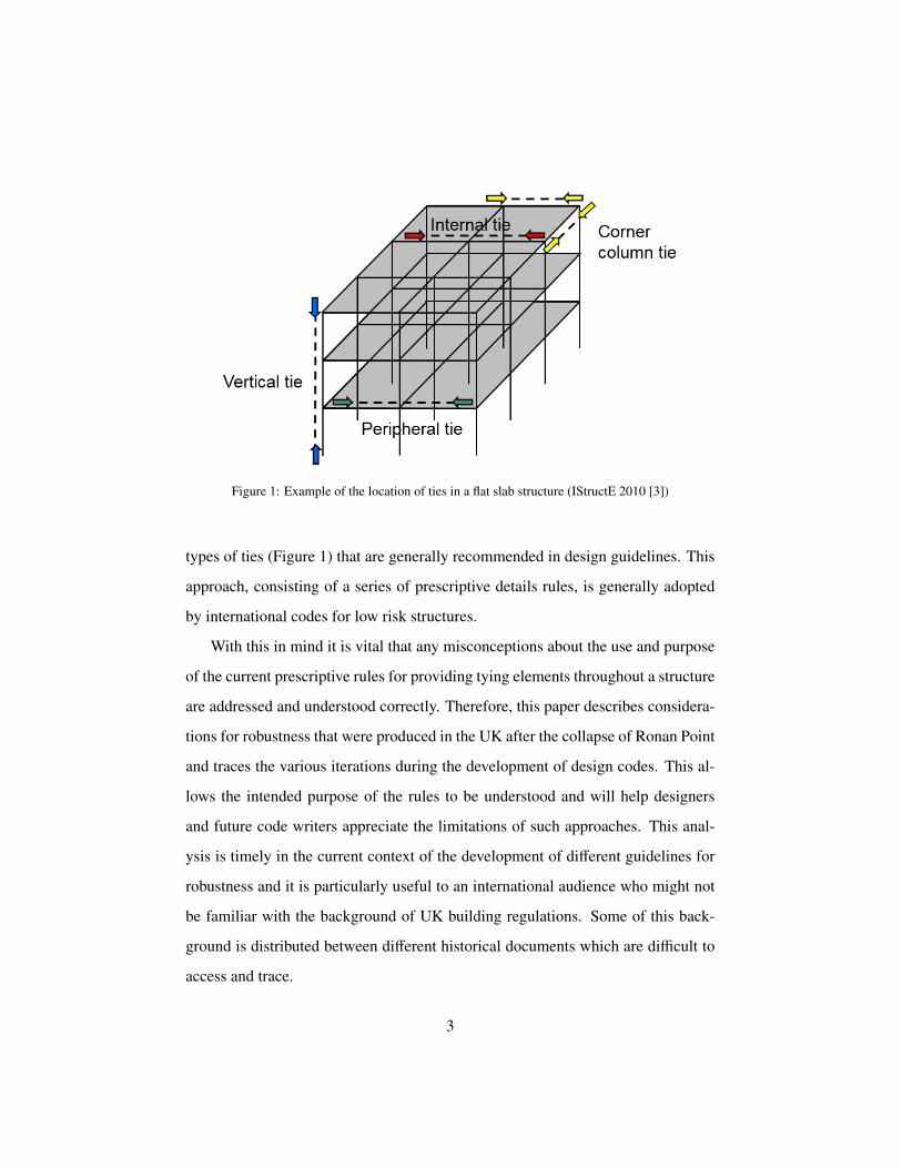
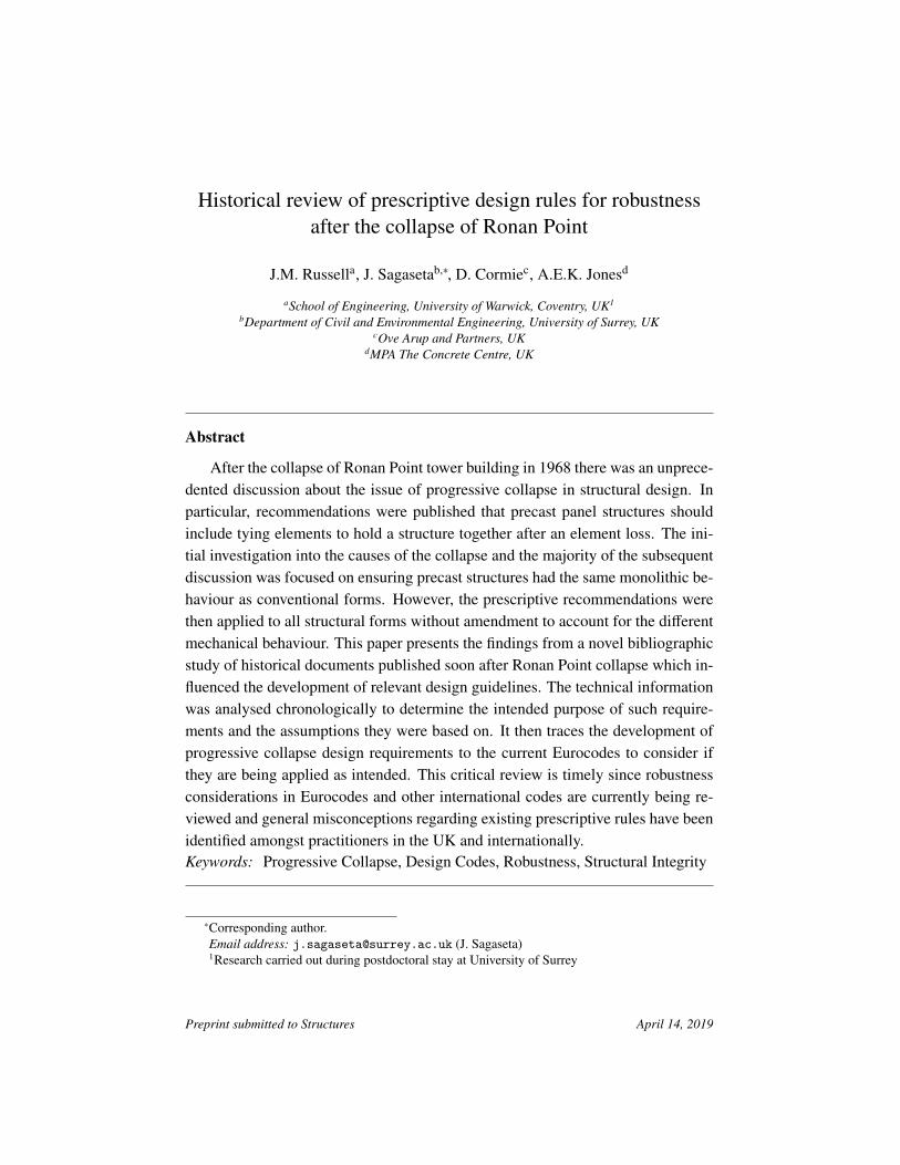
Figure 1: Example of the location of ties in a flat slab structure (IStructE 2010 [3])
types of ties (Figure 1) that are generally recommended in design guidelines. This
approach, consisting of a series of prescriptive details rules, is generally adopted
by international codes for low risk structures.
With this in mind it is vital that any misconceptions about the use and purpose
of the current prescriptive rules for providing tying elements throughout a structure
are addressed and understood correctly. Therefore, this paper describes considera-
tions for robustness that were produced in the UK after the collapse of Ronan Point
and traces the various iterations during the development of design codes. This al-
lows the intended purpose of the rules to be understood and will help designers
and future code writers appreciate the limitations of such approaches. This anal-
ysis is timely in the current context of the development of different guidelines for
robustness and it is particularly useful to an international audience who might not
be familiar with the background of UK building regulations. Some of this back-
ground is distributed between different historical documents which are difficult to
access and trace.
3
2. Ronan point collapse and the immediate discussion
Much in depth discussion has been made about the collapse of Ronan Point
tower building [1, 5], and this paper does not seek to readdress this analysis or
provide additional information on the event itself. Rather the focus is on the imme-
diate discussion and reports that occurred (1968-1972) and their consequences for
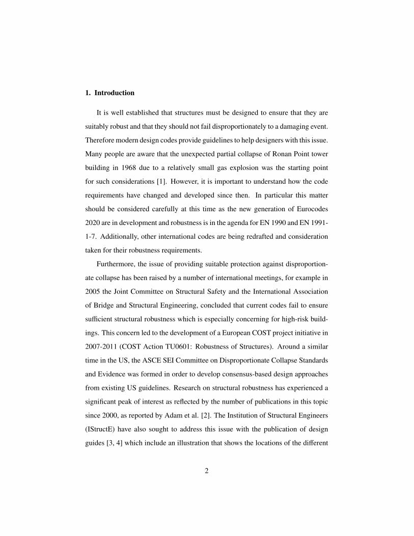
the structural engineering community. Figure 2 provides a summary of some of the
most significant events, covering a time scale from 1905 with an early example of a
progressive collapse described in [6] with large social impact but negligible impact
on codes and robustness considerations at that time, until 2025 with the expected
end of the work on the second generation of Eurocodes.
2.1. Initial reports
Shortly after the collapse the UK Ministry of Housing and Local Government
released Circular 62/68, ‘Flats constructed with pre-cast concrete panels. Appraisal
and strengthening of existing high blocks: Design of new blocks’ [11], which re-
quired an investigation into the susceptibility to progressive collapse for all exist-
ing pre-cast load bearing buildings over 6 storeys and a check for fire and wind
requirements. It described a method for resisting progressive collapse by provid-
ing an alternative load path for the loadings above a removed wall, by utilising
“arching, beam, or cantilever action by the provision of suitable reinforcement”
[11]. It alternatively specifies that elements could have a local resistance of 5psi
(34kN/m2), described as the maximum likely pressure from an explosion in a block
of flats, although the scientific justification of this value was debated [27].
Over the next few months the Institution of Structural Engineers (IStructE)
released 5 reports (RP-68-01 to RP-68-05) [12, 13, 15, 28, 29] outlining the In-
stitution’s response and opinion to these matters. The first report [12] opened by
emphasising their recommendations were focused on prefabricated concrete panels
4
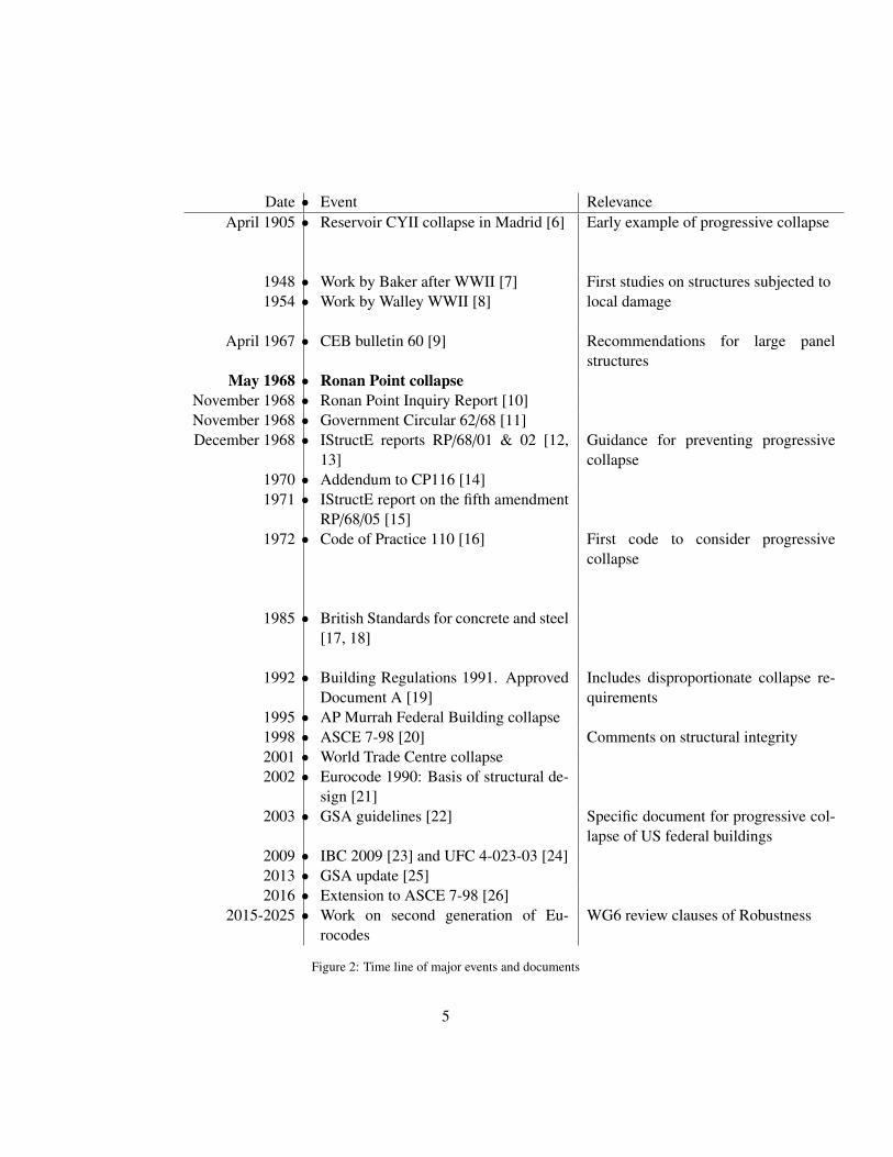
Date • Event RelevanceApril 1905 • Reservoir CYII collapse in Madrid [6] Early example of progressive collapse
1948 • Work by Baker after WWII [7] First studies on structures subjected tolocal damage1954 • Work by Walley WWII [8]
April 1967 • CEB bulletin 60 [9] Recommendations for large panelstructures
May 1968 • Ronan Point collapseNovember 1968 • Ronan Point Inquiry Report [10]November 1968 • Government Circular 62/68 [11]December 1968 • IStructE reports RP/68/01 & 02 [12,
13]Guidance for preventing progressivecollapse
1970 • Addendum to CP116 [14]1971 • IStructE report on the fifth amendment
RP/68/05 [15]1972 • Code of Practice 110 [16] First code to consider progressive
collapse
1985 • British Standards for concrete and steel[17, 18]
1992 • Building Regulations 1991. ApprovedDocument A [19]
Includes disproportionate collapse re-quirements
1995 • AP Murrah Federal Building collapse1998 • ASCE 7-98 [20] Comments on structural integrity2001 • World Trade Centre collapse2002 • Eurocode 1990: Basis of structural de-
sign [21]2003 • GSA guidelines [22] Specific document for progressive col-
lapse of US federal buildings2009 • IBC 2009 [23] and UFC 4-023-03 [24]2013 • GSA update [25]2016 • Extension to ASCE 7-98 [26]
2015-2025 • Work on second generation of Eu-rocodes
WG6 review clauses of Robustness
Figure 2: Time line of major events and documents
5
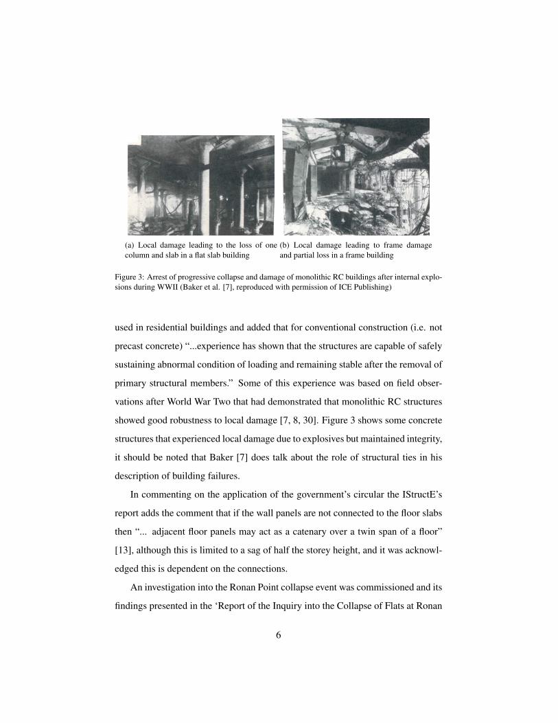
(a) Local damage leading to the loss of onecolumn and slab in a flat slab building
(b) Local damage leading to frame damageand partial loss in a frame building
Figure 3: Arrest of progressive collapse and damage of monolithic RC buildings after internal explo-sions during WWII (Baker et al. [7], reproduced with permission of ICE Publishing)
used in residential buildings and added that for conventional construction (i.e. not
precast concrete) “...experience has shown that the structures are capable of safely
sustaining abnormal condition of loading and remaining stable after the removal of
primary structural members.” Some of this experience was based on field obser-
vations after World War Two that had demonstrated that monolithic RC structures
showed good robustness to local damage [7, 8, 30]. Figure 3 shows some concrete
structures that experienced local damage due to explosives but maintained integrity,
it should be noted that Baker [7] does talk about the role of structural ties in his
description of building failures.
In commenting on the application of the government’s circular the IStructE’s
report adds the comment that if the wall panels are not connected to the floor slabs
then “... adjacent floor panels may act as a catenary over a twin span of a floor”
[13], although this is limited to a sag of half the storey height, and it was acknowl-
edged this is dependent on the connections.
An investigation into the Ronan Point collapse event was commissioned and its
findings presented in the ‘Report of the Inquiry into the Collapse of Flats at Ronan
6
Point, Canning Town’ published in the same year [10]. This report was thorough
in its consideration of the failures involved ranging from flawed structural design
to poor workmanship and out of date codes of practice. However, it is clear that
its conclusions are intended to be very narrow in application. This arises from the
fact that the report limited itself to precast system buildings, and indeed only those
of the construction used for Ronan Point. The main recommendations from the
report are that consideration should be given to the use of town gas in high rise
buildings, existing, tall ‘system-built blocks’ should be appraised and that codes of
practice should be brought up to date. This last point focused on wind loading on
high buildings and for large concrete panel construction.
There is however a simply worded recommendation presented that “the Build-
ing Regulations should include provisions dealing with progressive collapse.” The
report commented that the existing steel or reinforced concrete frame tall buildings
“...are not liable to progressive collapse and accordingly nobody turned their minds
to this specific question” [10], and so, according to report, it was only due to the
use of new construction techniques that resulted in this becoming an issue.
The report also identified that large concrete panel system buildings requires
“continuity at the joints of a kind strong and tough enough to stand both the initial
shock of local damage and the abnormal and, in detail, unforeseeable loads they
may subsequently have to bear” [10]. In fact, the aim was to achieve a non-brittle
monolithic structure. The authors state “Reinforced concrete buildings constructed
of in-situ concrete have most of the properties required” [10].
The report authors stress the fact that it does not consider it appropriate that
they should attempt to deal in detail with the measures needed to strengthen the
joints. However, they comment that a “generous and general distribution” of mild
steel between panels would have improved the design.
In summary, any comments from the Ronan Point inquiry are very narrow in
7
terms of application, dealing exclusively with large precast concrete panels. The
recommendations presented are mainly concerned with the out of date Code of
Practice for wind loading and the use of town gas in tall structures, as well as the
introduction of a code of practice for panel buildings. It is also understood that
the authors believed that progressive collapse is not a major concern for frame
structures or in-situ concrete. Finally, while broadly stating the requirement for
a structure to be tied together the report makes no detailed comment on how this
should be achieved, or the design loads that would be appropriate. Additionally,
common later terms such as cantilever, catenary, ties, robustness or sudden column
loss are not used at all.
2.2. Early discussions on code amendments
A Short and J R Miles’ 1969 [31] paper on the new draft requirements for
large panel structures [14] describe the purpose of tying elements as to “ensure
the integrity of the construction, to prevent structures from falling apart.” This is
contrasted to monolithic structures where “these ties forces are generally present
owing to the inherent nature of the construction” [31].
Short and Miles also expand further on the role of ties in different locations
(see Figure 1 for examples), stating the reinforcement along the peripheral will
strengthen the corner and “produces the necessary bridging reinforcement to take
care of the danger of progressive collapse caused by the elimination of an ex-
ternal wall” [31]. Whereas internal and peripheral ties “are intended to impart
a quasi-monolithic character to the floor” [31] which could allow membranes to
form. Within their conclusion they state that due to the lack of reliable scientific
evidence the “requirements were based on the intuitive judgement of experienced
structural engineers backed by a design study.”
Finally, although they recognised that the addendum was only intended for
8
large-panel structures they argued that the principles should be “considered for
other types of construction that are sensitive to exceptional and unforeseen load-
ings” [31]. This went beyond the report into the collapse of Ronan point which
was limited to precast construction, and recommended only investigation and new
regulation for large panel structures. However, the government decided the fifth
amendment to the building regulations should to apply to all structural forms. This
was a matter of some controversy and was among the issues debated on this sub-
ject in the UK House of Commons, as Nicholas Ridley MP (himself a qualified
civil engineer) stated, “Instead of accepting the recommendations of the report,
[the government] launched out on their own with a series of building regulations
which are far too technical and far too expensive and which will do great harm to
the advancement of building techniques” [27].
However, the Minister of State for Housing at the time, Mr Reginald Free-
son MP, stated that “The amendment proposals are primarily aimed at protection
against the effects of damage, however it is caused, or against progressive collapse
experience, however it might be caused, in the future” [27] and then explained why
the new provisions were applied broader than just precast structures. He viewed
that the “new mandatory requirement should not be selective in its application and
so not be thought to penalise a particular form of construction” [27]. He also ar-
gued that some framed and brick buildings were still susceptible to progressive
collapse, but the new requirements would not be unreasonable for structures that
were not susceptible and that “the new requirements have been deliberately drawn
up in fairly functional terms...to facilitate their application to varying forms of con-
struction and to permit of the flexibility of design” [27].
By the time the code of practice for the structural use of precast concrete,
CP116 [14], was updated to include the Ronan Point Inquiry Report’s recommen-
dations, some aspects took the lead from a previously published CEB recommenda-
9
tions for large panel precast structures [9]. This document suggested that the panels
should be tied together to maintain continuity. However, the purpose of those ties
was to resist horizontal loadings (e.g. wind, seismic, eccentricities) and forces due
to differential settlement and no considerations was given to element loss. Simi-
larly, as result of Ronan Point and the subsequent updating of regulations, Fintel
and Schultz conducted investigations during the 1970’s into the integrity of large
panel buildings in America [32]. Their recommendations of including ties between
elements to maintain integrity and bridge over potential damage were developed as
a basis for the minimum tie force requirements still in use in the ACI Standard 318
[33].
After building regulations and some codes of practice were updated to include
the Ronan Point Inquiry Report’s recommendations, the Institution of Structural
Engineers published the report “Stability of modern buildings” [34] which notes
on the topic of providing alternative load paths that “...there is no fully detailed de-
sign procedure by which to implement this philosophy. There is, however, plenty
of practical experience to demonstrate that a damaged structure will remain stable
in favourable circumstances after an incident that has severely damaged and pos-
sibly removed a section or component of the framework” [34]. This report also
viewed that the formation of a catenary or membrane could maintain stability af-
ter a damaging event, as long as the floors and columns are tied together. For
box-frame structures they also state that for an effective tie “The magnitude is ob-
viously related to the span of the floor and beam components and should be capable
of sustaining practical catenary effects” [34].
Research into the issue of progressive collapse continued into the 1970’s and
80’s with particular interest in concrete structures and catenary action [32, 35–38].
However, there was no major changes to design approaches as a result of these later
studies, except for some rules introduced for detailing specific structural elements.
10
The original report into the Ronan Point collapse made clear that its recommen-
dations were intended only for precast, indeed it states that RC frames are unlikely
to undergo progressive collapse. Its proposed method of preventing progressive
collapse was to attempt to give precast structures the same monolithic behaviour
that occurs naturally with in-situ construction. Although it is now known that RC
frames and slab structures may still be susceptible to progressive collapse, (for ex-
ample the Skyline Plaza in 1973 and Sampoong Department Store in 1995 [39])
this is due to their different mechanical behaviour (e.g. brittle connection failures,
long spans, less optimal construction control compared to prefabricated structures)
rather than their loss of continuity.
3. Review of code tying force requirements
3.1. CEB bulletin 60
In 1967 CEB released a report entitled ‘International recommendations for the
design and construction of large-panel structures’ [9]. This document included
some broad guidance for ensuring the continuity of precast panels such as “Within
the thickness of each floor, or close to the floor, mechanically continuous steel
“ties” should be provided in both directions.” Both peripheral and internal ties (or
chains to use the original French term) were required, although these are specified
between panels and not flooring elements. The purpose of these are described as:
• resist the forces acting on the external panels (in their load-bearing
role) owing to inaccuracies of installation;
• resist the horizontal reactions directly exerted by the panels (wind
and earthquake);
• resist the tensile forces developed in the floors performing their
wind-bracing function;
11
• resist where necessary the horizontal components of the diagonal
forces in the wall panels subjected to tensile load by the effect of
lateral forces, and transmit the horizontal floor reactions to the
windward edges of the wind-bracing cantilevers;
• resist the tensile forces developed in the walls if differences of
level develop in the supports
From a review of these clauses it is clear that although most of the terminology
used (e.g. peripheral and internal ties, continuity, cantilevers etc.) is similar to
later progressive collapse design guidelines, these requirements were not intended
to address the sorts of extreme scenarios that occur after a sudden column loss.
Although, it has been noted that if Ronan Point had been designed and constructed
to comply with CEB bulletin 60 the consequences of the event would have been
significantly lower [40].
3.2. CP 110 : Part 1 : 1972
One of the earliest national codes to include consideration for progressive col-
lapse was Code of Practice 110 in 1972 [16]. Here the requirement is stated that,
“The layout of the structure on plan, and the interaction between the structural
members, should be such as to ensure a robust and stable design...there should be
reasonable probability that it will not collapse catastrophically under the effect of
misuse or accident.” It is also clarified that the structure is not expected to resist ex-
treme loads of events, but not fail disproportionately. To meet this requirement ties
are recommended to maintain the structures robustness. Initially the purpose of ties
in buildings was stated in the additional clause that “...the ties should be so placed
as to provide the best assistance in resisting by cantilever, catenary or other actions
the results of extreme damage by accidental causes.” Emphasis added to highlight
12
the mechanisms by which the ties are utilised for, and therefore the expected state
of the structure for which they are relevant.
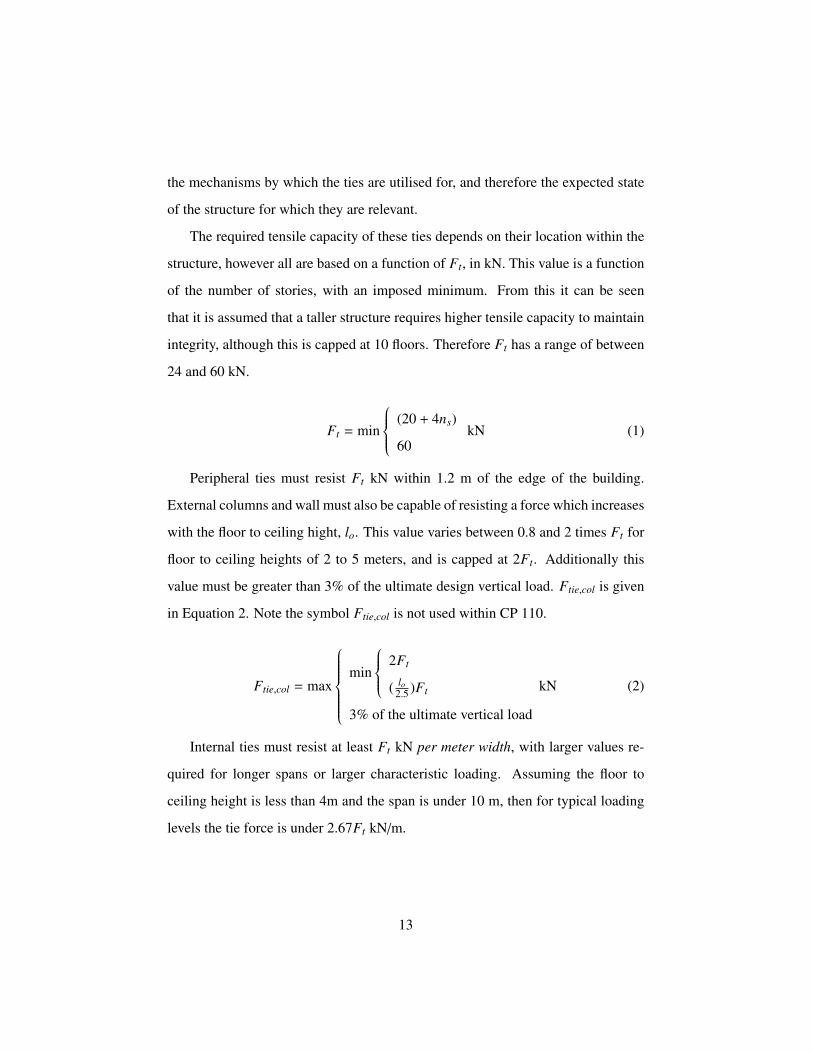
The required tensile capacity of these ties depends on their location within the
structure, however all are based on a function of Ft, in kN. This value is a function
of the number of stories, with an imposed minimum. From this it can be seen
that it is assumed that a taller structure requires higher tensile capacity to maintain
integrity, although this is capped at 10 floors. Therefore Ft has a range of between
24 and 60 kN.
Ft = min
(20 + 4ns)
60kN (1)
Peripheral ties must resist Ft kN within 1.2 m of the edge of the building.
External columns and wall must also be capable of resisting a force which increases
with the floor to ceiling hight, lo. This value varies between 0.8 and 2 times Ft for
floor to ceiling heights of 2 to 5 meters, and is capped at 2Ft. Additionally this
value must be greater than 3% of the ultimate design vertical load. Ftie,col is given
in Equation 2. Note the symbol Ftie,col is not used within CP 110.
Ftie,col = max
min
2Ft
( lo2.5 )Ft
3% of the ultimate vertical load
kN (2)
Internal ties must resist at least Ft kN per meter width, with larger values re-
quired for longer spans or larger characteristic loading. Assuming the floor to
ceiling height is less than 4m and the span is under 10 m, then for typical loading
levels the tie force is under 2.67Ft kN/m.
13
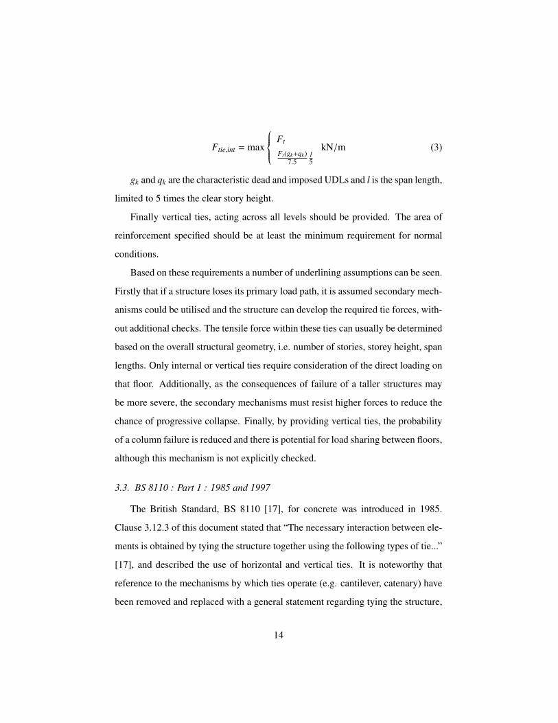
Ftie,int = max
Ft
Ft(gk+qk)7.5
l5
kN/m (3)
gk and qk are the characteristic dead and imposed UDLs and l is the span length,
limited to 5 times the clear story height.
Finally vertical ties, acting across all levels should be provided. The area of
reinforcement specified should be at least the minimum requirement for normal
conditions.
Based on these requirements a number of underlining assumptions can be seen.
Firstly that if a structure loses its primary load path, it is assumed secondary mech-
anisms could be utilised and the structure can develop the required tie forces, with-
out additional checks. The tensile force within these ties can usually be determined
based on the overall structural geometry, i.e. number of stories, storey height, span
lengths. Only internal or vertical ties require consideration of the direct loading on
that floor. Additionally, as the consequences of failure of a taller structures may
be more severe, the secondary mechanisms must resist higher forces to reduce the
chance of progressive collapse. Finally, by providing vertical ties, the probability
of a column failure is reduced and there is potential for load sharing between floors,
although this mechanism is not explicitly checked.
3.3. BS 8110 : Part 1 : 1985 and 1997
The British Standard, BS 8110 [17], for concrete was introduced in 1985.
Clause 3.12.3 of this document stated that “The necessary interaction between ele-
ments is obtained by tying the structure together using the following types of tie...”
[17], and described the use of horizontal and vertical ties. It is noteworthy that
reference to the mechanisms by which ties operate (e.g. cantilever, catenary) have
been removed and replaced with a general statement regarding tying the structure,
14
however the section continues in an almost identical wording and requirement to
CP 110, indicating they are based on the same assumption. The requirements for
vertical ties is expanded on in this standard and introduces the additional require-
ment that the ties must able to carry in tension the vertical design loading on that
column from one floor. The update to BS 8110 in 1997 [41] made no change to the
requirements.
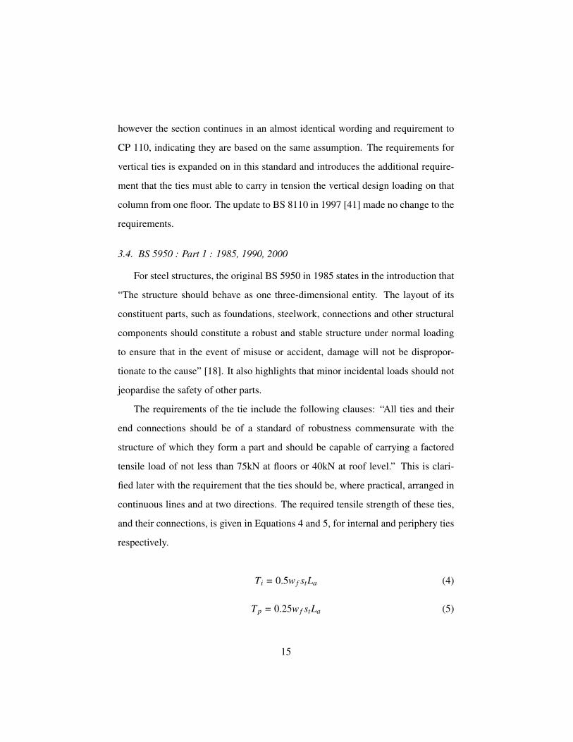
3.4. BS 5950 : Part 1 : 1985, 1990, 2000
For steel structures, the original BS 5950 in 1985 states in the introduction that
“The structure should behave as one three-dimensional entity. The layout of its
constituent parts, such as foundations, steelwork, connections and other structural
components should constitute a robust and stable structure under normal loading
to ensure that in the event of misuse or accident, damage will not be dispropor-
tionate to the cause” [18]. It also highlights that minor incidental loads should not
jeopardise the safety of other parts.
The requirements of the tie include the following clauses: “All ties and their
end connections should be of a standard of robustness commensurate with the
structure of which they form a part and should be capable of carrying a factored
tensile load of not less than 75kN at floors or 40kN at roof level.” This is clari-
fied later with the requirement that the ties should be, where practical, arranged in
continuous lines and at two directions. The required tensile strength of these ties,
and their connections, is given in Equations 4 and 5, for internal and periphery ties
respectively.
Ti = 0.5w f stLa (4)
Tp = 0.25w f stLa (5)
15
where w f is the factored loading, per area, on the floor. st is the spacing be-
tween ties and La is the length of the tie under investigation.
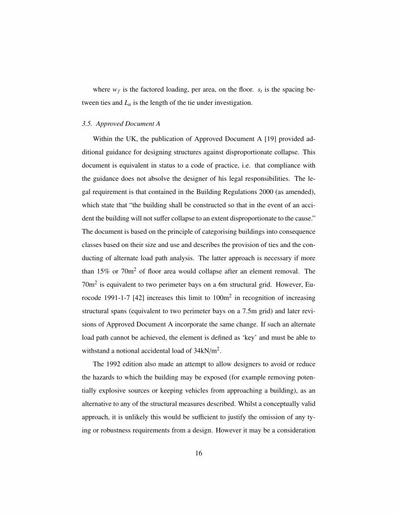
3.5. Approved Document A
Within the UK, the publication of Approved Document A [19] provided ad-
ditional guidance for designing structures against disproportionate collapse. This
document is equivalent in status to a code of practice, i.e. that compliance with
the guidance does not absolve the designer of his legal responsibilities. The le-
gal requirement is that contained in the Building Regulations 2000 (as amended),
which state that “the building shall be constructed so that in the event of an acci-
dent the building will not suffer collapse to an extent disproportionate to the cause.”
The document is based on the principle of categorising buildings into consequence
classes based on their size and use and describes the provision of ties and the con-
ducting of alternate load path analysis. The latter approach is necessary if more
than 15% or 70m2 of floor area would collapse after an element removal. The
70m2 is equivalent to two perimeter bays on a 6m structural grid. However, Eu-
rocode 1991-1-7 [42] increases this limit to 100m2 in recognition of increasing
structural spans (equivalent to two perimeter bays on a 7.5m grid) and later revi-
sions of Approved Document A incorporate the same change. If such an alternate
load path cannot be achieved, the element is defined as ‘key’ and must be able to
withstand a notional accidental load of 34kN/m2.
The 1992 edition also made an attempt to allow designers to avoid or reduce
the hazards to which the building may be exposed (for example removing poten-
tially explosive sources or keeping vehicles from approaching a building), as an
alternative to any of the structural measures described. Whilst a conceptually valid
approach, it is unlikely this would be sufficient to justify the omission of any ty-
ing or robustness requirements from a design. However it may be a consideration
16
when dealing with existing buildings, particularly those designed pre-Ronan Point.
This approach, as an alternative, has been deleted from subsequent editions of the
approved document.
In 2004 the document was revised to extend the previous requirements, man-
dating horizontal tying for buildings below five stories for the first time (except
single-occupancy residential dwellings). Above five stories, the previously-existing
general requirements continued to apply (horizontal and vertical tying, alternate
load path analysis and key element design). Basements became excluded from the
storey count, provided they satisfy Class 2B, potentially to reduce the requirements
for horizontal tying. A significant difference with the 2004 edition was the subtle
change to the layout and punctuation that resulted in horizontal tying no longer
being required with notional element removal. However, in previous editions of
Approved Document A, the intent is quite clear: horizontal ties are to be provided
regardless of whether vertical tying or alternate load path analysis is chosen.
This edition also includes the option of “effective anchorage of suspended slabs
to walls” given as an alternative to horizontal tying. Although similar to the pro-
vision of horizontal ties, reference to masonry code reveals that it is intended to
describe deemed-to-satisfy details in masonry construction of joist hangers for tim-
ber floor joists or built-in ends of precast concrete slabs which satisfy the Class 2A
requirement without tying reinforcement. The Code gives no detail about the re-
silience of the details proposed, but as they are only valid for Class 2A buildings,
it can be inferred that they provide less resilience than full horizontal tying. Addi-
tionally, note that as prior to 2004, horizontal tying did not apply in buildings less
than 5 stories, this potentially allowed a reduced requirement for the masonry and
timber industries for this building class.
Finally, in 2004 the Class 3 category, was introduced covering the highest risk
buildings, for which systematic risk assessment is required. Intended for buildings
17
exceeding 15 stories or 5000m2 per storey, those containing hazardous substances
or processes, stadia and grandstands, or buildings into which the public are ad-
mitted in significant numbers. The IStructE (practical guide to robustness) also
recommend that certain buildings merit treatment as Class 3 buildings because of
their value, vulnerability or the consequences of their failure. [4, 43].
3.6. Eurocode
With the introduction of the Eurocodes, a number of changes were made re-
garding robustness considerations in design. However, the majority of these re-
fer to a reorganisation of design requirements rather than a substantial change in
methodologies.
3.6.1. EN 1990
Eurocode EN 1990 [21] states as a basic requirement that “A structure shall
be designed and executed in such a way that it will be not be damaged by events
such as: explosion, impact, and the consequences of human errors, to an extent
disproportionate to the original cause.” On inspection, this is just a restatement of
the requirement that existed in CP 110. Under the list of options for avoiding or
limiting the potential damage within EC0’s basic requirements, three are applicable
for this study. These are “selecting a structural form and design that can survive
adequately the accidental removal of an individual member or a limited part of
the structure, or the occurrence of acceptable localised damage; avoiding as far
as possible structural systems that can collapse without warning; and tying the
structure together” [21].
18
3.6.2. EN 1991-1-7
EN 1991-1-7 [42] provides in the information for tie strengths, and for the first
time, explicitly separates frame and load-bearing wall construction, although its
requirements cover all structural material forms.
For framed structures, the ties must be able to carry the required tensile load,
according to Equations 6 and 7 for internal and perimeter ties respectively which
given as a function of the loading and the span length. These equations and method-
ology are similar to the previous British Standard for steel structures (BS 5950
[18]), see Section 3.4. The separate requirement for external columns or walls to
be tied in has been moved to the different material sections.
Ti = 0.8(gk + ψqk)sL or 75kN, whichever is the greater. (6)
Tp = 0.4(gk + ψqk)sL or 75kN, whichever is the greater. (7)
For load bearing wall cases, a structure in Class 2b risk group, typically build-
ings between 4 and 15 storeys, requires horizontal ties in the floors. The value of
Ft is similar in practice for internal and peripheral ties as previous codes, although
the load used in the equivalent equation is that for the accidental situation rather
than the ultimate limit state.
3.6.3. EN 1992-1
For concrete structures EN 1992-1 [44] provides further instruction. Firstly, the
purpose of tying systems is stated clearly: “Structures that are not designed to with-
stand accidental actions shall have a suitable tying system, to prevent progressive
collapse by providing alternative load paths after local damage” [44]. Then follows
the list of four types of ties, that have been mentioned in previous codes above. i.e.
peripheral, internal, horizontal column/wall ties and vertical ties. Section 9.10.2.2
19
in EN 1992-1, provides recommendations for these tie forces, however, the UK
National Annex differs in calculating these values. For peripheral ties, EC states
Ftie,per from Equation 8.
Ftie,per = li · q1 ≤ Q2 (8)
where li is the length of the end-span and EC recommends q1 = 10kN/m and
Q2 = 70kN. However, the UK decision in their National Annex is to maintain the
previous equations from the CP110 and BS 8110, with Q2 = 60kN and defines q1
with Equation 9.
q1 = (20 + 4no)li (9)
This can be simplified down to the system used for CP 110 and BS 8110, i.e.
Ftie,per = Ft.
For internal ties, EC simply recommends a value of 20 kN/m while the UK
again sticks with existing equation. For most applications the UK requirements of
tying forces are higher than the EC suggested values. For floors without screeds
and where ties are grouped at beam lines then EC suggests Equation 10 while the
UK uses the previous internal tie equation.
Ftie = q3 · (l1 + l2)/2 ≤ q4 (10)
with q3 = 20kN/m and q4 = 70kN. l1 and l2 are the span lengths either side of
the beam.
Edge columns and walls should be tied horizontally into the structure. EC
recommends Ftie, f ac = 20kN/m and Ftie,col = 150kN. Again, the UK decision is
20
to maintain the historical approach, with the same value for columns and walls,
although the units differ.
3.7. US provisions
Although this paper is focused on the direct development of UK progressive
collapse guidelines as a result of the Ronan Point collapse, other counties have
naturally developed their own recommendations [2].]. Many of these international
codes show the evolution of some of the early concepts introduced soon after Ro-
nan Point such as the concept of robustness itself or the fundamentals behind the
notional element removal approach. This evolution was particularly relevant in the
United States of America, especially after events such as the Alfred P. Murrah Fed-
eral Building collapse in Oklahoma in 1995 and the World Trade Center in New
York in 2001 leading to a number of well established codes such as ACI 318 [33],
ASCE 7-16 [26], IBC 2009 [23], UFC 4-023-03 [24] and GSA [25].
ASCE 7-16 [26] describes a requirement of general structural integrity with
similar language to Eurocode 1990 stating that a structure must be able “to sustain
local damage with the structural system as a whole remaining stable and not being
damaged to an extent disproportionate to the original local damage”. It lists conti-
nuity, redundancy and ductility as methods to achieve this. UFC 4-023-03 Design
of Buildings to Resist Progressive Collapse [24] describes a tie force method very
similar to European approaches stating that “the building is mechanically tied to-
gether, enhancing continuity, ductility, and development of alternate load paths”
by use of vertical, longitudinal, transverse, and peripheral ties. Significantly, the
existing structural members can only be used to provide the tie force if they are
cable of undergoing a 0.20rad (11◦) rotation. The latest General Services Admin-
istration guidelines (GSA) [25] move away from tie force requirement to focus on
alternative load path methods requiring full analysis of the structure after the loss
21
of a load bearing element. Stevens et al. [45] provides an overview of Department
of Defense (DoD) requirements for high risk structures, typically government or
military.
The majority of approaches mentioned above remain threat independent, al-
though in cases where a known threat exists more detailed design is provided
for. More usual designs include tie force checks for low risk locations and al-
ternative load path analysis in more critical scenarios. A general classification of
design methods against disproportionate collapse was put forward by the ASCE
SEI Sub-committee on Terminology and Procedures [46], dividing methods into
non-structural and structural. The non-structural methods focuses on event control
whereas the structural focuses on the collapse resistance (robustness and vulnera-
bility), e.g. alternative load path method, segmentation, protection, increased local
resistance (key element design). A similar design strategy is proposed in Eurocodes
[42] for accidental design situations although in this case the same methods are
classified according to whether the accidental action is identified or the method
focuses on limiting the extent of localised failure. In both classifications, it is un-
derstood that the tying approach would contribute towards limiting the extent of
the localised failure and provide integrity.
4. Discussion of code development at an international context
From considering all the development of the requirements, culminating in the
current Eurocode guidelines, a number of points can be made. Firstly, it is clear
that although the collapse of Ronan Point, which triggered the introduction of ro-
bustness considerations in design guidelines, only occurred due to a combination
of the nature of the structural form used and deficiencies in design, the solutions
were equally applied to all forms of construction. This was not due to technical
22
considerations, but to make the new codes of practice more general in their appli-
cation and to prevent the precast industry becoming at an economic disadvantage.
Related to this, the initial purpose of the ties was to help precast structures be-
have as monolithic insitu concrete ones, with the view that these forms were able
to resist disproportionate collapse. It is now known that such structures may fail
despite continuity, therefore, the same methodology may not be appropriate for all
structural forms.
The majority of the knowledge about collapse of structures in 1968 was based
on observations during World War Two and specialised knowledge for the precast
industry. There is very little experimental and theoretical research from the time
period to back up the prescriptive rules proposed to prevent progressive collapse,
and even less to provide evidence for the tying forces and values prescribed.
It appears the early codes intended tie requirements to be a broad, prescrip-
tive method of ensuring that a structure does not fail disproportionately to a local
damaging event. However, the actual method by which this is accomplished, is
general at best and vague at worst with different mechanisms described at different
times (e.g. catenary, membrane, beam action, arching, cantilever). In addition, due
to the prescriptive nature of the tying requirements it is not possible to quantify
their effectiveness or what minimum level of robustness they provide. However,
despite its limitations, these and similar rules are used in many codes in addition
to Eurocode (e.g. ASCE 7-16 [26], IBC 2009 [23], UFC 4-023-03 [24] and also
the Chinese code CECS 392:2014 [47] and Canadian NBCC 1995 [48]). However,
such an approach is not universal as other international codes, such as GSA 2013
[25], NYC BC 2014 [49] (New York) and NCC 2016 [50] (Australia), exclude this
method. See Adam et al. for more information [2].
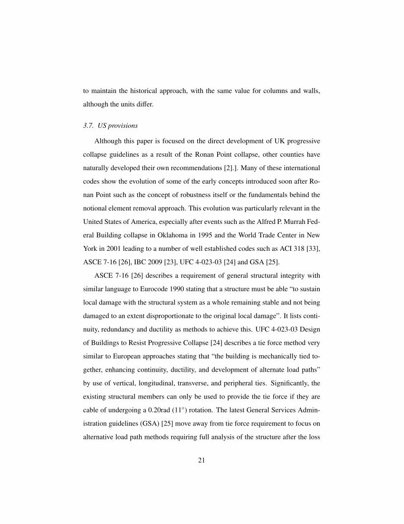
The traditional prescriptive based codes do not give any consideration to the
fact that a structure may not be able to utilise these ties without deforming to an
23
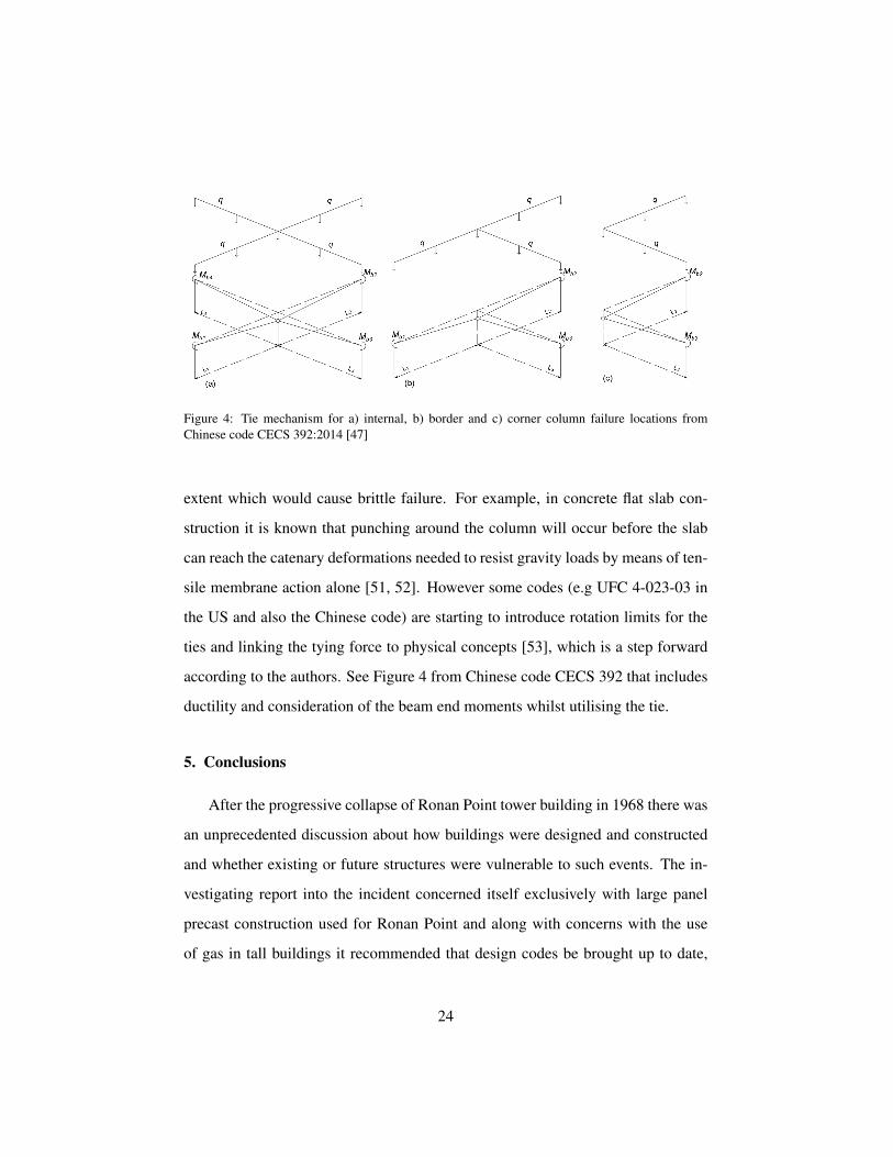
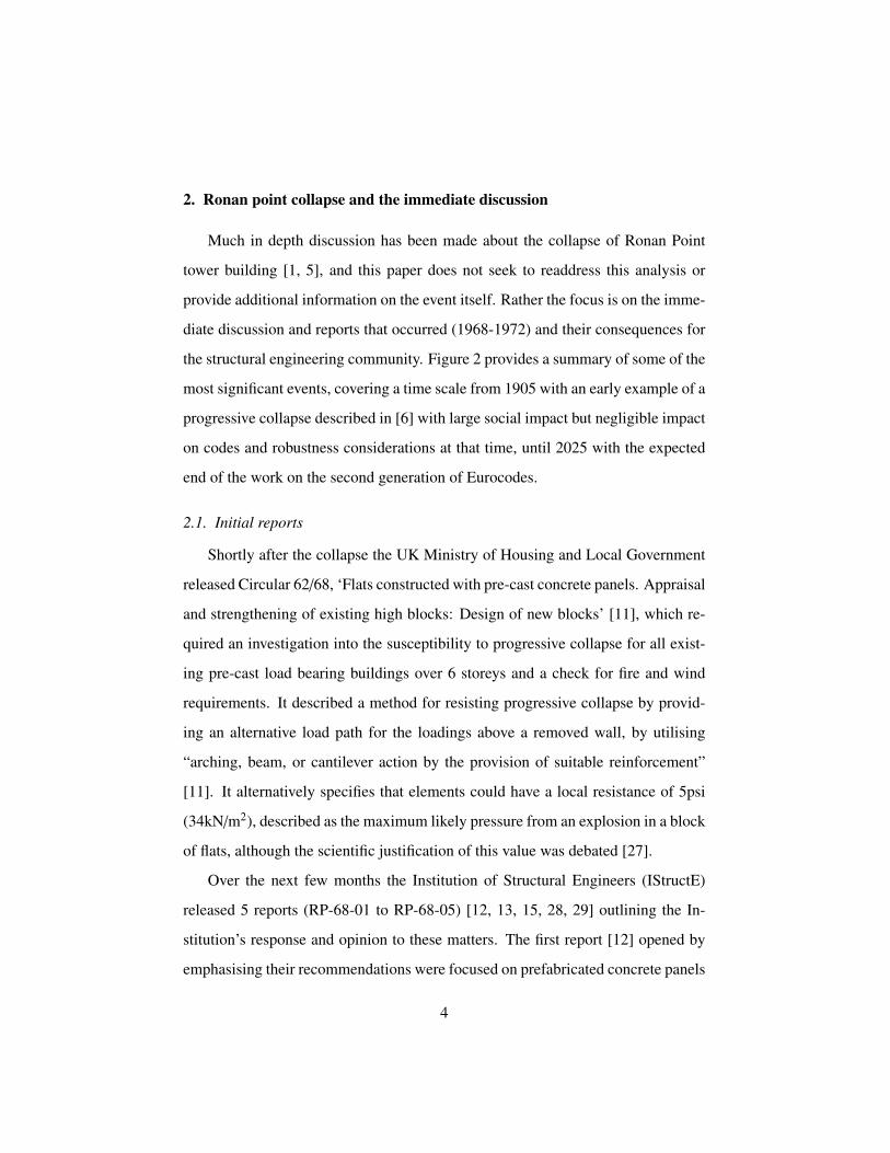
Figure 4: Tie mechanism for a) internal, b) border and c) corner column failure locations fromChinese code CECS 392:2014 [47]
extent which would cause brittle failure. For example, in concrete flat slab con-
struction it is known that punching around the column will occur before the slab
can reach the catenary deformations needed to resist gravity loads by means of ten-
sile membrane action alone [51, 52]. However some codes (e.g UFC 4-023-03 in
the US and also the Chinese code) are starting to introduce rotation limits for the
ties and linking the tying force to physical concepts [53], which is a step forward
according to the authors. See Figure 4 from Chinese code CECS 392 that includes
ductility and consideration of the beam end moments whilst utilising the tie.
5. Conclusions
After the progressive collapse of Ronan Point tower building in 1968 there was
an unprecedented discussion about how buildings were designed and constructed
and whether existing or future structures were vulnerable to such events. The in-
vestigating report into the incident concerned itself exclusively with large panel
precast construction used for Ronan Point and along with concerns with the use
of gas in tall buildings it recommended that design codes be brought up to date,
24
especially for wind loading. Soon after the accident the British Government re-
leased amendments to the building regulations requiring considering of progres-
sive collapse, and applied these specifications to all structural forms. From the
bibliographic study carried out in this work it was concluded that:
1) The new requirements for ties are based on a methodology proposed in CEB
bulletin 60 [9], this document predated the collapse of Ronan Point and was
concerned with maintaining integrity across precast joints due to minor ec-
centricities and so they were not intended for use with other structural forms
or for dealing with extreme events such as element removal. The literature
shows different interpretations of the purpose of the tying approach, includ-
ing preventing local failure and maintaining integrity after member loss.
2) While the original investigators were no doubt aware of the limitations and
the focus of their recommendations, the current form of the guidelines, de-
veloped through the British Standards and now the Eurocodes, is not directly
based on their scenarios. Although the provisions were based on the best in-
formation and experience available at that time, further experimental testing
and solid research is needed to support these prescriptive rules.
3) There are significant mechanical differences in the behaviour of large precast
panels and modern construction methods and therefore the same approach
may not be appropriate. This causes a problem for drafting general rules
for structures (such as for the Eurocodes) as the vulnerability and behaviour
could be very different for different structural forms.
4) Although the original intention of the ties was to prevent brittle failure, this is
not explicitly checked and therefore it is not certain that the tie, or secondary
25
mechanism can form without further failures occurring. This issue is being
addressed in some codes and is an important area of future development.
5) Future revisions for international design codes such the Eurocodes should
be orientated towards improving confidence in prescriptive rules and their
range of applicability. Such rules should be reviewed based on the variability
of the risk of progressive collapse, form of construction, hazards identified
and robustness considerations during the design, construction and operation
phases.
There have been very few cases of complete progressive collapse in the last
few decades and so, whilst useful for practical cases of low risk, it is not possible
to quantify the efficiency of implementing ties in building structures. In many
cases, designers are unaware of the intended purpose and assumptions behind these
guidelines. In some cases applying these guidelines may lead to the false sense of
security and in some other cases designers might lean towards alternative load path
approaches which are quantitative. With this in mind it is therefore recommended
that designers using the current tie guidelines should also take into account the
required mechanisms for tie to be utilised after an extreme event. In particular
joint ductility for large deformations and the prevention of brittle failures (e.g.
shear failures) is vital for such an approach to be effective.
Acknowledgements
This work is part of a research project financially supported by the EPSRC Im-
pact Acceleration Account held by the University of Surrey (grant ref: EP/K503939);
linked with a previous project funded by the Engineering and Physical Sciences
Research Council of the U.K. (grant ref: EP/K008153/1). The authors would also
26
like to thank the IStructE librarians for their assistance in obtaining some of the
documents discussed in this paper.
References
[1] C. Pearson and N. Delatte. Ronan point apartment tower collapse and its
effect on building codes. Journal of Performance of Constructed Facilities,
19(2):172–177, 2005.
[2] Jose M Adam, Fulvio Parisi, Juan Sagaseta, and Xinzheng Lu. Research and
practice on progressive collapse and robustness of building structures in the
21st century. Engineering Structures, 173:122–149, 2018.
[3] Institution of Structural Engineers. Practical guide to structural robustness
and disproportionate collapse in buildings. IStructE, London, UK, 2010.
[4] D. Cormie (Arup). Manual for the systematic risk assessment of high-risk
structures against disproportionate collapse. IStructE Ltd, 2013.
[5] M. N. Bussell and A. E. K. Jones. Robustness and the relevance of ronan
point today. The Structural Engineer, 88(23):20–25, 2010.
[6] Eduardo Dıaz-Pavon Cuaresma, Javier Leon Gonzalez, and Jorge Ley Urzaiz.
Robustness: The quality Ribera missed in 1905. Hormigon y Acero,
68(283):e23–e34, 2017.
[7] J. F. Baker, Edward Leader Williams, and D. Lax. The design of framed
buildings against high-explosive bombs. In The civil engineer in war: A
symposium of papers on war-time engineering problems, pages 3–80. Thomas
Telford Ltd, 1948.
[8] F Walley. The design of bomb-resisting structures against H.E. attack. 1954.
Available in the Walley Collection at the (UK) Institution of Civil Engineers.
[9] C V [tr] Amerongen. International recommendations for the design and con-
struction of large-panel structures. Technical report, C. & C. A., 1967. A
translation of the report in French ’Recommandations internationales uni-
fiees pour le calcul et l’execution des constructions en panneaux assembles
27
de grand format’. Paris, Comite Europeen du Beton, April 1967. pp. 198.
Information bulletin no. 60.
[10] H. Griffiths, A. Pugsley, and O. Saunders. Report of the inquiry into the
collapse of flats at Ronan Point, Canning Town. H. M. S. O, [S.l.], 1968.
presented by H. Griffiths, Sir A. Pugsley and Sir O. Saunders.
[11] Ministry of Housing Government and Local. Flats constructed with pre-cast
concrete panels - appraisal and strengthening of existing high blocks: design
of new blocks. Technical report, HMSO, 1968. Ministry of Housing and
Local Government Circular 62/68.
[12] IStructE. Ronan Point - the aftermath - RP/68/01: Structural stability and
the prevention of progressive collapse, and covering letter titled ’Ronan Point
collapse. Technical report, IStructE, 1968.
[13] IStructE. Ronan Point - the aftermath - RP/68/02: Notes for guidance which
may assist in the interpretation of Appendix 1 to Ministry of Housing and
Local Government Circular 62/68. Technical report, IStructE, 1968.
[14] BSI. CP 116: Addendum No. 1:1970 - The structural use of precast con-
crete. Large-panel structures and structural connections in precast concrete.
Addendum to CP 116:1965 and CP 116- 2:1969., 1970.
[15] IStructE. Ronan Point - the aftermath - RP/68/05: The resistance of buildings
to accidental damage. Technical report, IStructE, 1971.
[16] BSI. CP 110-1:1972 - Code of practice for the structural use of concrete.
Design, materials and workmanship, 1972.
[17] BSI. BS8110 : Part 1 : 1985: structural use of concrete: Part 1: Code of
practice for design and construction, 1985.
[18] BSI. BS5950 : Part 1 : 1985: Structural use of steelwork in building. Code
of practice for design. Rolled and welded sections, 1985.
[19] HM Government. Building regulations 2000. approved document a, 2010.
[20] American Society of Civil Engineers. Minimum design loads and associated
criteria for buildings and other structures (7-16), 1998.
28
[21] BSI. BS EN1990:2002: Eurocode 0 - Basis of structural design, 2002.
[22] General Services Administration (GSA). Alternate path analysis & design
guidelines for progressive collapse resistance, 2003.
[23] ICC IBC. International building code, 2009.
[24] US DoD. UFC 4-023-03: Design of buildings to resist progressive collapse,
2009.
[25] General Services Administration (GSA). Alternate path analysis & design
guidelines for progressive collapse resistance, 2016.
[26] American Society of Civil Engineers. Minimum design loads and associated
criteria for buildings and other structures (7-16), 2017.
[27] UK House of Commons debate. HC Deb 09 March 1970 vol 797 cc1059-
1080.
[28] IStructE. Ronan Point - the aftermath - RP/68/03: Guidance on the design of
domestic accommodation in loadbearing brickwork and blockwork to avoid
collapse following an internal explosion, and covering letters titled ’Ronan
Point collapse’ and ’Loadbearing brickwork and blockwork: RP/68/02. Tech-
nical report, IStructE, 1969.
[29] IStructE. Ronan Point - the aftermath - RP/68/04: The Building (fifth amend-
ment) Regulations 1970: notes for discussion at a meeting to be held IStructE
30 June 1970. Technical report, IStructE, 1970.
[30] DG Christopherson. Structural defence. British Ministry of Home Security,
1945.
[31] A. Short and J. R. Miles. Large panel structures : Notes on draft addendum 1
to CP 116 (1965). Building Research Station, [S.l.], 1969. Building Research
Station Current Papers ; BRS CP 30/69 Building Research Station (Great
Britain).
[32] Mark Fintel and Donald M Schultz. A philosophy for structural integrity of
large panel buildings. PCI Journal, 21(3):46–69, 1976.
[33] Standard, ACI. ACI 318-14 Building Code Requirements for Structural Con-
29
crete, 2014.
[34] Engineers Institution of Structural. Stability of modern buildings. Institution
of Structural Engineers, London (11 Upper Belgrave St., SW1X 8BH), 1971.
GB7206735 bnb The Institution of Structural Engineers.
[35] B Lewicki and SO Olesen. Limiting the possibility of progressive collapse.
1974.
[36] PE Regan. Catenary action in damage concrete structures. Special Publica-
tion, 48:191–224, 1975.
[37] Bruce R Ellingwood and EV Leyendecker. Approaches for design against
progressive collapse. Journal of the Structural Division, 104(3):413–423,
1978.
[38] OA Pekau, ZA Zielinski, AWK Lee, and D Hum. Dynamic effects of panel
failure in precast concrete shear walls. Structural Journal, 85(3):277–285,
1988.
[39] NJ Gardner, J Huh, and L Chung. Lessons from the sampoong department
store collapse. Cement and Concrete Composites, 24(6):523–529, 2002.
[40] B R Ellingwood, R. Smilowitz, D O Dusenberry, D Duthinh, Hai S Lew,
and Nicholas J Carino. Best practices for reducing the potential for progres-
sive collapse in buildings. NIST Interagency/Internal Report (NISTIR)-7396,
2007.
[41] BSI. BS8110 : Part 1 : 1997: structural use of concrete: Part 1: Code of
practice for design and construction, 1997.
[42] BSI. BS EN1991-1-7:2006: Eurocode 1 - Actions on structures - Part 1-7:
General actions - Accidental actions, 2006.
[43] G Harding and J Carpenter. Disproportionate collapse of’class 3’buildings:
the use of risk assessment. Structural Engineer, 87(15-16), 2009.
[44] BSI. NA to BS EN 1992-1-1:2004 - UK National Annex to Eurocode 2.
Design of concrete structures. General rules and rules for buildings, 2004.
[45] David Stevens, Brian Crowder, Doug Sunshine, Kirk Marchand, Robert
30
Smilowitz, Eric Williamson, and Mark Waggoner. Dod research and criteria
for the design of buildings to resist progressive collapse. Journal of Structural
Engineering, 137(9):870–880, 2011.
[46] U Starossek, R Smilowitz, M Waggoner, KJ Rubenacker, and Marco Haber-
land. Report of the terminology and procedures Sub-Committee (SC1): Rec-
ommendations for design against disproportionate collapse of structures. In
Proceedings of the Structures Congress, pages 2090–2103, 2011.
[47] China Association for Engineering Construction Standardization (CECS).
Cecs 292:2014 code for anti-collapse design of building structures, 2014.
[48] National Research Council of Canada. Canadian commission on building and
fire codes, 1995.
[49] NYC Department of Buildings. Building code (chapter 16 structural design),
2014.
[50] Australian Building Codes Board (ABCB). National Construction Code
(NCC): Volumes 1 & 2. Council of Australian Governments, 2016.
[51] P. E. Regan. Report 89: Behaviour of reinforced concrete flat slabs. Tech-
nical report, Construction Industry Research and Information Association
(CIRIA), 1981.
[52] J. Sagaseta, N. Ulaeto, and J. Russell. Structural robustness of concrete flat
slab structures. Special Publication Honoring Neil M. Hawkins, ACI SP-
315, Federation internationale du bton (fib) and American Concrete Institute
(ACI), 315:273–298, 2017.
[53] Y. Li, X. Z. Lu, H. Guan, and L. P. Ye. An improved tie force method for pro-
gressive collapse resistance design of reinforced concrete frame structures.
Engineering Structures, 33(10):2931–2942, 2011.
31
Related Documents