Submitted By : Himanshu Singh (B.Tech. 3 rd yr. MECHANICAL ENGG.) Achal Duvedi (B.Tech. 3 rd yr. MECHANICAL ENGG.) Girish (B.Tech. 3 rd yr. MECHANICAL ENGG.) INSTITUTE :

Welcome message from author
This document is posted to help you gain knowledge. Please leave a comment to let me know what you think about it! Share it to your friends and learn new things together.
Transcript
Submitted By :Himanshu Singh (B.Tech. 3rd yr. MECHANICAL ENGG.)
Achal Duvedi (B.Tech. 3rd yr. MECHANICAL ENGG.)
Girish (B.Tech. 3rd yr. MECHANICAL ENGG.)
INSTITUTE :
Page2
Summer Training Report at NTPC Limited, Auraiya
V.B.S.PURVANCHAL UNIVERSITY,JAUNPUR
S.No CONTENTS
PAGE.No
1.
2.
3.
4.
5.
6.
7.
8.
9.
10.
11.
Vision and Mission of NTPC
NTPC culture
Acknowledgement
Basic components of a power plant
Generator protection
Transformer protection
Introduction to AuGPP
Generator system
6.6 kV switchboard
Switchyard
Types of faults
03
04
05
06 to 14
15 to 20
20 to 21
22 to 23
23 to 24
24 to 25
25 to
V.B.S.PURVANCHAL UNIVERSITY,JAUNPUR
Page3
Summer Training Report at NTPC Limited, Auraiya
26
27 to 31
INDEX
V.B.S.PURVANCHAL UNIVERSITY,JAUNPUR
Page4
Summer Training Report at NTPC Limited, Auraiya
VISION ANDMISSION OF NTPCVISION: “To be one of the world’s largest and best power utilities, powering
India’s growth.”
MISSION: “Develop and provide reliable power, related products and services at
competitive prices, integrating multiple energy sources with innovative and eco–
friendly technologies and contribute to society"
Make available reliable and quality power in
increasingly large quantities at competitive prices and
ensure timely realization of revenues.
Adopt a broad based capacity portfolio including Hydro
Power, LNG, Nuclear Power, and non conventional and
eco-friendly fuels
Plan and speedily implement power projects using state-
of- the art technologies.
Be an integrated utility by implementing strategic
diversifications in areas such as power trading
distribution, transmission, coal mining, coal
beneficiation etc.
V.B.S.PURVANCHAL UNIVERSITY,JAUNPUR
Page5
Summer Training Report at NTPC Limited, Auraiya
Develop a strong portfolio of profitable businesses in
overseas markets including technical services,
generation assets etc.
Continuously attract and develop committed human
resources to match world standards.
Lead fundamental and applied research for adoption of
the state-of-the-art technologies, breakthrough
efficiency improvements and new fuels.
Lead developmental efforts in the Indian power sector
including assisting state utility reform, policy
recover etc.
Be a socially responsible corporate entity with thrust
on environment protection, ash utilization, community
development, and energy conservation.
NTPC: CULTURE
Core values are both intensely and widely
shared.
Climate of high behavioral control.
V.B.S.PURVANCHAL UNIVERSITY,JAUNPUR
Page6
Summer Training Report at NTPC Limited, Auraiya
Low employee turnover.
High agreement among the employees, for what
NTPC stands for.
All these point to the fact that strong
cohesiveness, loyalty and organization
commitment exist in NTPC lowering he
attrition Rate.
V.B.S.PURVANCHAL UNIVERSITY,JAUNPUR
Page7
Summer Training Report at NTPC Limited, Auraiya
ACKNOWLEDGEMENT
First of all, we would like to thank the enterprise NTPC Ltd. (National Thermal Power Corporation Ltd.) for giving us an opportunity to work and get experience and to know how much hard work an engineer has to do for keeping the job proper. We would like to thank Mr. S.K. SINGH, Mr. NITIN GANGWAR, Mr. N.K. PANDEY for their constant support and guidance. They taught us how to use the theoretical fundamentals in practical and how to apply the principles that we study in books. They also made us familiar with the latest trends coming up in the engineering field.
At last, we would like to thank once more all the people who were guiding either directly or indirectly for this training to become more proficient.
V.B.S.PURVANCHAL UNIVERSITY,JAUNPUR
Page8
Summer Training Report at NTPC Limited, Auraiya
Himanshu Singh Achal Duvedi Girish
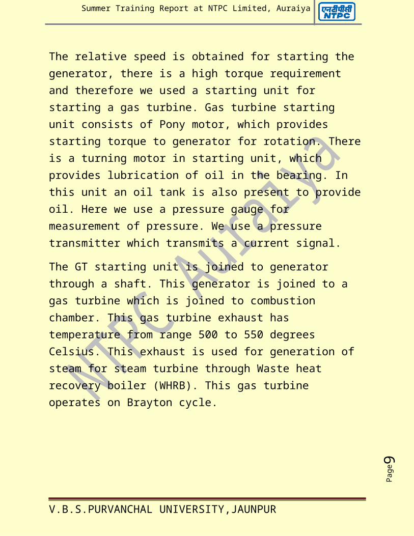
Basic components of a gas power plant :
1. Gas turbine: In the gas turbine, the power for driving both the compressor and the generator is produced. The energy is supplied tothe turbine in the form of hot gases as they come from the combustion chamber. The kinetic energy of the gases is transferred to the rotor in the turbine by means of rotating blades. The combustion gases, come from the preceding stage,are accelerated in the stator blade while, simultaneously the inlet pressure is reduced by vectorial addition with circumferential speed.
V.B.S.PURVANCHAL UNIVERSITY,JAUNPUR
Page9
Summer Training Report at NTPC Limited, Auraiya
The relative speed is obtained for starting the generator, there is a high torque requirement and therefore we used a starting unit for starting a gas turbine. Gas turbine starting unit consists of Pony motor, which provides starting torque to generator for rotation. Thereis a turning motor in starting unit, which provides lubrication of oil in the bearing. In this unit an oil tank is also present to provideoil. Here we use a pressure gauge for measurement of pressure. We use a pressure transmitter which transmits a current signal.
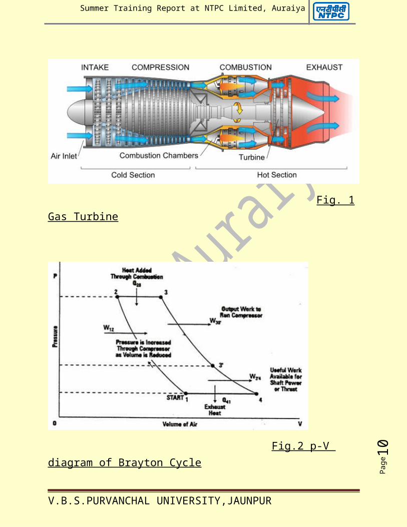
The GT starting unit is joined to generator through a shaft. This generator is joined to a gas turbine which is joined to combustion chamber. This gas turbine exhaust has temperature from range 500 to 550 degrees Celsius. This exhaust is used for generation of steam for steam turbine through Waste heat recovery boiler (WHRB). This gas turbine operates on Brayton cycle.
V.B.S.PURVANCHAL UNIVERSITY,JAUNPUR
Page10
Summer Training Report at NTPC Limited, Auraiya
Fig. 1Gas Turbine
Fig.2 p-V diagram of Brayton Cycle
V.B.S.PURVANCHAL UNIVERSITY,JAUNPUR
Page11
Summer Training Report at NTPC Limited, Auraiya
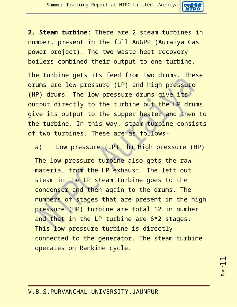
2. Steam turbine: There are 2 steam turbines in number, present in the full AuGPP (Auraiya Gas power project). The two waste heat recovery boilers combined their output to one turbine.
The turbine gets its feed from two drums. These drums are low pressure (LP) and high pressure (HP) drums. The low pressure drums give its output directly to the turbine but the HP drums give its output to the supper heater and then tothe turbine. In this way, steam turbine consistsof two turbines. These are as follows-
a) Low pressure (LP) b) High pressure (HP)
The low pressure turbine also gets the raw material from the HP exhaust. The left out steam in the LP steam turbine goes to the condenser and then again to the drums. The numbers of stages that are present in the highpressure (HP) turbine are total 12 in number and that in the LP turbine are 6*2 stages. This low pressure turbine is directly connected to the generator. The steam turbine operates on Rankine cycle.
V.B.S.PURVANCHAL UNIVERSITY,JAUNPUR
Page12
Summer Training Report at NTPC Limited, Auraiya
Fig.3 Steam Turbine Fig.4 Rankine Cycle
3. Fuels: In the plant, mainly two fuels are used. They are as follows:
a) Natural gas
b) Naphtha
Gas turbine is capable of burning a range of fuels including naphtha, distillates, crude oil,and natural gas. Selection of fuels depends on several factors including fuel availability, fuel cost and cleanness of fuel.
Natural gas is ideal fuel because it provides high thermal efficiency and reliability with twooperation and maintenance cost. Liquid fuels, particularly heavy oils, usually contain
V.B.S.PURVANCHAL UNIVERSITY,JAUNPUR
Page13
Summer Training Report at NTPC Limited, Auraiya
contaminants, which cause corrosion and fueling in the gas turbine. Contaminants, which cannot be removed from the fuel, may leave deposit in the gas turbine, which reduces performance and adds to maintenance costs.
Dual fuel systems are commonly used enabling thegas turbine to burn back up fuels. When the primary fuel source is not available, dual fuel systems can be used fire both fuels simultaneously.
Liquid fuel system: it consists of the liquid fuels storage and handling system. The liquid fuel storage and handling system provides means for unloading storage and distribution of the fuel oil within the plant and typically composedthe following major components.
a) Fuel oil unloading pumps
b) Fuel oil transfer pumps
c) Fuel oil storage tanks
d) Flow motor
e) Strainers
f) Pressure and level control
V.B.S.PURVANCHAL UNIVERSITY,JAUNPUR
Page14
Summer Training Report at NTPC Limited, Auraiya
g) Distribution piping
Naphtha pressurizing system: By the forwarding pumps Naphtha is pumped up to the GTs and kept under recirculation for firing, separated pressure pump sallied filters and measurements and recirculation system is used. This pressurizing is required because in the naphtha burner this fuel is mechanically atomized. Thereis no other medium like air etc. to be used for this atomization.
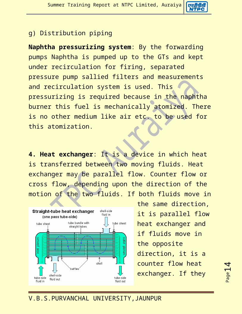
4. Heat exchanger: It is a device in which heat is transferred between two moving fluids. Heat exchanger may be parallel flow. Counter flow or cross flow, depending upon the direction of the motion of the two fluids. If both fluids move in
the same direction, it is parallel flow heat exchanger and if fluids move in the opposite direction, it is a counter flow heat exchanger. If they
V.B.S.PURVANCHAL UNIVERSITY,JAUNPUR
Page15
Summer Training Report at NTPC Limited, Auraiya
flow normal to each other, it is a cross flow heat exchanger. There are 4 types of heat exchanger-
a) Shell type
b) Single type
c) Double type
d) Plate type
Fig.5 Heat Exchanger
5. Compressor: In the gas power plants, the mainfunction of the compressor is to increase the pressure of the air and its temperature is also increased in the compressor room, first of all there is a silicon tank which is used for absconding the moisture contents of air and thenthis air is compressed and sent to the combustion chamber for the combustion. The number of stages involved in the compressor chamber is 19.
6. Combustor: In the combustor chamber, combustion takes place between fuel and
V.B.S.PURVANCHAL UNIVERSITY,JAUNPUR
Page16
Summer Training Report at NTPC Limited, Auraiya
compressed air from compression room. The combustion is a chemical reaction between a fueland oxygen, which proceeds at the fast rates with the release of energy in the room of the heat. The temperature of the combustor chamber is usually 1100 degree Celsius. This temperatureheat energy is sending to the turbine. The number of thermocouples in the combustor chamberis 18. They are used for the measurement of the temperature indication of the combustor chamber.
7. Condenser: The exhaust steam of the steam turbine condenses into water in the condenser where cooling water circulates. After heat reflecting from the condenser chamber, this water is sent to the pump. A condenser could be a reversible constant pressure heat rejection.
8. Nozzle: A nozzle is a device which increases the velocity or kinetic energy of a fluid at theexpense of its pressure drop. When air pressure,at nozzle end is very low, then there is less leakage to the surrounding and back pressure will be high. But as we increase the air
V.B.S.PURVANCHAL UNIVERSITY,JAUNPUR
Page17
Summer Training Report at NTPC Limited, Auraiya
pressure, then there is more leakage to the surrounding and the back pressure decreases.
9. Filters: For combustion process in the combustion, there is requirement of oxygen. We take oxygen from atmosphere as air in the atmosphere contains impure particles (dust particles). Therefore we use a filter, for removal of dust particles from the atmosphere air and to get pure oxygen for combustion in thecombustor chamber.
10. Generator: In gas power plant, generators are used for generation of electricity. Basically generator has two parts:
a) Stator
b) Rotor
Stator is the stationary part of the generator on which field winding is present. Rotor is the rotating part of the generator on which armaturewinding is present. When the rotor rotates, the flux linked with the conductors changes.
V.B.S.PURVANCHAL UNIVERSITY,JAUNPUR
Page18
Summer Training Report at NTPC Limited, Auraiya
Therefore EMF is induced based on the principle of Faraday’s laws.
In gas power plant, total six generators are used (one for each turbine).
11. Valves: In gas power plant, valves are used to control the flow. On the basis of activating,control valves are classified as follows:
a) Pneumatic valves- These type of valves are operated by air. These are fast controlling valves. These are as follows:
(i) Diaphragm actuated:
--- Position control type (can be adjusted to various levels)
--- On soft type
b) Position type:
Air to case- fails safe open Air to open- fails safe close
Air to close means gas pipe is connected to the upper surface of the diaphragm.
V.B.S.PURVANCHAL UNIVERSITY,JAUNPUR
Page19
Summer Training Report at NTPC Limited, Auraiya
(ii) Piston (cylindrical) actuated:
--- Electric valve: these are operated by electricity and are slow
--- Manual valve: these are operated by humans
--- Hydraulic valve: these are operated by liquids.
On the basis of mechanical construction:
a) Globe valve: these are also called control valves.
b) Gate valve: these are called on/off valve.
c) Needle valve: these are used for small flow.
d) Non-return valve: these are used for unidirectional flow.
e) Butterfly valve: these are used for large flow.
12. Pump: After heat rejection, in the condenserthe water is sent to the pump. For the pump, theideal process would be reversible adiabatic
V.B.S.PURVANCHAL UNIVERSITY,JAUNPUR
Page20
Summer Training Report at NTPC Limited, Auraiya
compression of this liquid ending at the initialpressure (increase its pressure).
In the gas power plant, there is centrifugal type pump. In this type of pump, inlet and outlet are connected to the peripheral of the pump. After pumping, outlet water is sent to theboiler.
13. Pipe: In gas power plant, there are different colours of pipe for easy detection:
a) Sky blue shows air pipe
b) Yellow shows gas pipe
c) Green shows water pipe
d) Brown shows naphtha or fuel pipe
V.B.S.PURVANCHAL UNIVERSITY,JAUNPUR
Page21
Summer Training Report at NTPC Limited, Auraiya
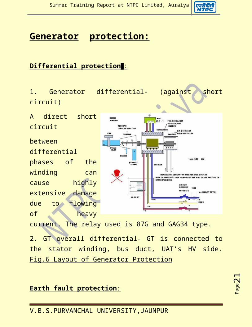
Generator protection:
Differential protection :
1. Generator differential- (against shortcircuit)
A direct shortcircuit
betweendifferentialphases of thewinding cancause highlyextensive damagedue to flowingof heavycurrent. The relay used is 87G and GAG34 type.
2. GT overall differential- GT is connected tothe stator winding, bus duct, UAT’s HV side.Fig.6 Layout of Generator Protection
Earth fault protection :
V.B.S.PURVANCHAL UNIVERSITY,JAUNPUR
Page22
Summer Training Report at NTPC Limited, Auraiya
1. Stator earth fault protection- The secondaryof the transformer is shorted through loadingresistance (0.42 ohm). If insulation is damagedthen earth fault occurs. Generator earth faultcurrent flows in the primary of the neutralgrounding transformer. As a result, the voltageacross the resistor is developed which activatesstator E/F sensing relay. In this relay, 95% isused for phases and 5% for neutral so that itmay confirm fault from the neutral side or fromthe phase side.
---- Stator stand by E/F: the relay is connectedacross an open delta of the generator PTsecondary windings. When there is no E/F, thesum of the phase voltages of the generator andhence the voltage across the relay is zero.
---- Stator inter turn fault: When leakageoccurs between the turns in the same phase of awinding, the induced voltage is reduced andthere will be a voltage difference between thecentre of the terminal voltage triangle andneutral of the machine. If inter turn faultoccurs in the machine, the CT carries a
V.B.S.PURVANCHAL UNIVERSITY,JAUNPUR
Page23
Summer Training Report at NTPC Limited, Auraiya
transient current and thereby pick up the relayand trips the generator.
2. Rotor earth fault- Earth fault may bedeveloped in rotor circuit due to failure ofinsulation occurring due to stresses offered bythe centrifugal forces. It is of 2 types:
---Single rotor E/F
--- Double rotor E/F
Single rotor earth fault is not harmful becauseno earth current circuit is completed. Butdouble rotor earth fault is harmful becauseimmediately E/F is completed, the internal turnswhich can burn the conductor causing severedamage to the rotor. Due to double E/F leakagecurrent flows through brushes which may bedamaged.
Negative phase sequence:
Three phase balanced load produces a reactionfield which is constant and rotatessynchronously with the rotor field system. Anyunbalanced condition could be resolved intopositive, negative and zero sequence components.
V.B.S.PURVANCHAL UNIVERSITY,JAUNPUR
Page24
Summer Training Report at NTPC Limited, Auraiya
The +ve sequence is similar to the balancedload. The zero sequence component does notproduce armature reaction. The -ve sequencecomponent is similar to that of the +ve sequencebut the resulting reaction field rotates in theopposite direction. Hence the flux produced bythe negative phase sequence current cuts therotor at double the rotational speed therebyinducing double frequency currents. As a result,eddy currents produced are very large and causesevere heating of the rotor windingsparticularly damper windings. The losses in therotor are proportional to the square of thedegree of the unbalance.
Generator back up impedance protection :
Impedance relay sensing (back up) is up to thebusbars. A three phase zone impedance relay isprovided for the backup protection of generatoragainst external three phase and phase to phasefaults in the 400/220 kV system. It should beconnected to trip the generator after a timedelay of 1 to 1.5 seconds so that the generator
V.B.S.PURVANCHAL UNIVERSITY,JAUNPUR
Page25
Summer Training Report at NTPC Limited, Auraiya
is tripped only when 400/220 kV protection hasnot cleared the faults even in the second zone.
Loss of excitation protection :
Sudden loss of excitation in an alternator makesthe generator to run as an induction generator.Generally all the generators should be designedto run as induction generator with a reducedload for a short period but the rotor will getoverheated from the induced current flowing inthe rotor iron, particularly at the retainingrings of the rotor. Due to loss of excitation itwill draw the reactive power from the grid(MVAR) or takes excitation from system and theremay be a voltage dip in the system which is notdesirable from system point of view. When lossof excitation is accompanied by undervoltage, itwill initiate Class A trip otherwise Class Btrip if the grid is able to sustain the voltagedip.
Pole slipping :
Pole slipping may occur in the generator due toinstability. It causes severe shock to bothmachine and grid due to violent oscillations in
V.B.S.PURVANCHAL UNIVERSITY,JAUNPUR
Page26
Summer Training Report at NTPC Limited, Auraiya
both active and reactive power. The angulardisplacement of the rotor exceeds the stabilitylimit the rotor will slip a pole pitch usuallyknown as pole slipping.
Overvoltage or overfluxing :
The generator can develop dangerously highvoltage in the event of maloperation of AVR orload throws off while generator excitation isunder manual control. Since voltage generated isdirectly proportional to flux, quantity of fluxincreases at overvoltage. Due to increase offlux, losses in the stator increases due towhich core will get heated up and thus reducingthe life of the generator.
Low forward power protection :
When a generator is synchronized with the grid,it loses its driving force and the generatorremains in synchronization. The generator shouldbe isolated from the grid after the steam flowceases and the flow of power to grid reduces tominimum i.e. the point when the generator starts
V.B.S.PURVANCHAL UNIVERSITY,JAUNPUR
Page27
Summer Training Report at NTPC Limited, Auraiya
drawing power from the grid and acts as motor.If the turbine tripped or ESV closed, thegenerator trips with a time delay of 2 seconds.
Reverse power protection :
When the input to the turbine suddenly goes offand generator is in service delivering power tothe system, turbine will be subjected toexcessive thermal overstress, vibration anddistortion causing damage to the turbine. Sothere is a back up arrangement to trip thegenerator if it does not trip within 2 seconds.Reverse power protection acts in 2 stages-
---1st stage- reverse power relay operates after5 sec time delay and includes stop valueclosing/turbine trip.
--- 2nd stage- reverse power relay acts after 60sec time delay.
Local breaker back up protection :
When the main generator breaker fails either dueto-
V.B.S.PURVANCHAL UNIVERSITY,JAUNPUR
Page28
Summer Training Report at NTPC Limited, Auraiya
--- Mechanical failure
--- Trip circuit not healthy
This protection acts as back up to the maingenerator by tripping all the breakers connectedto that particular bus.
Under minimum frequency : In case of underfrequency excitation will be loaded. Underfrequency is also dangerous for turbine as itmay damage the HP blades.
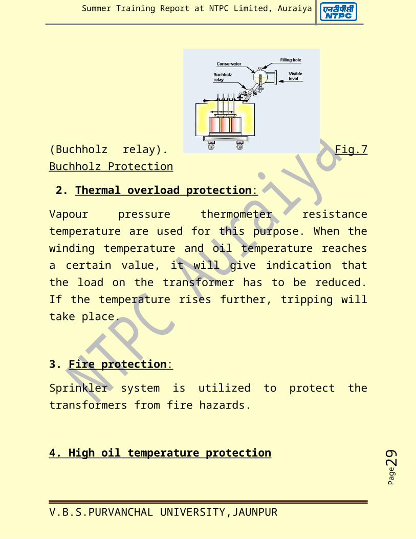
Transformer protection:1. Buchholz protection :
Any internal fault in the generator transformercauses the winding temperature to increaserapidly resulting in vaporization of oil. Thegenerated gas is utilized for relay operation
V.B.S.PURVANCHAL UNIVERSITY,JAUNPUR
Page29
Summer Training Report at NTPC Limited, Auraiya
(Buchholz relay). Fig.7Buchholz Protection
2. Thermal overload protection :
Vapour pressure thermometer resistancetemperature are used for this purpose. When thewinding temperature and oil temperature reachesa certain value, it will give indication thatthe load on the transformer has to be reduced.If the temperature rises further, tripping willtake place.
3. Fire protection :
Sprinkler system is utilized to protect thetransformers from fire hazards.
4. High oil temperature protection
V.B.S.PURVANCHAL UNIVERSITY,JAUNPUR
Page30
Summer Training Report at NTPC Limited, Auraiya
5. High winding temperature protection
6. Pressure relief valve (PRV)
7. Overfluxing protection : The condition ofoverfluxing could arise in case the voltage atthe machine terminal rises or its frequencydrops or both occurring simultaneously.
INTRODUCTION TO AuGPP :
V.B.S.PURVANCHAL UNIVERSITY,JAUNPUR
Page31
Summer Training Report at NTPC Limited, Auraiya
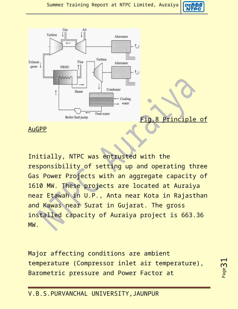
Fig.8 Principle ofAuGPP
Initially, NTPC was entrusted with the responsibility of setting up and operating threeGas Power Projects with an aggregate capacity of1610 MW. These projects are located at Auraiya near Etawah in U.P., Anta near Kota in Rajasthanand Kawas near Surat in Gujarat. The gross installed capacity of Auraiya project is 663.36 MW.
Major affecting conditions are ambient temperature (Compressor inlet air temperature), Barometric pressure and Power Factor at
V.B.S.PURVANCHAL UNIVERSITY,JAUNPUR
Page32
Summer Training Report at NTPC Limited, Auraiya
generator terminals. AuGPP has two combined cycle gas module each consisting of two gas turbines, waste heat recovery boilers (WHRB) andone steam turbine. The capacity of each Gas Turbine is 111.76 MW and that of Steam Turbine is 110 MW. Total capacity of each Module: 326 MW
Each generator output is connected to generator transformer (235/11.5 kV) by isolated phase bus duct. HV side of generator transformer is connected to 220 kV open type switchyard by overhead line.
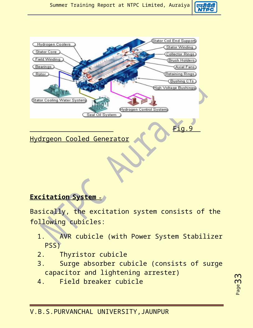
GENERATOR SYSTEM :
Generator –
The generator is of hydrogen cooled (rated hydrogen pressure = 2Kg/cm²) 3000 rpm, 50 Hz with static excitation system. The insulation ofstator winding is of Class F (type of insulation: impregnated epoxy resin mica).
V.B.S.PURVANCHAL UNIVERSITY,JAUNPUR
Page33
Summer Training Report at NTPC Limited, Auraiya
Fig.9 Hydrgeon Cooled Generator
Excitation System –
Basically, the excitation system consists of thefollowing cubicles:
1. AVR cubicle (with Power System StabilizerPSS)
2. Thyristor cubicle3. Surge absorber cubicle (consists of surgecapacitor and lightening arrester)
4. Field breaker cubicle
V.B.S.PURVANCHAL UNIVERSITY,JAUNPUR
Page34
Summer Training Report at NTPC Limited, Auraiya
The power for initial excitation of the generator is obtained from the 220V DC system.
Station Transformer – The auxiliary power of thepower station is supplied by two 220/6.9 kV (star-star connection) 27 MVA station transformers. It is of core type. HV side of thetransformer is connected to 220 kV switchyard byoverhead line. LV side is connected to 6.6 kV switchgear through non-segregated bus duct.
6.6 kV SWITCHBOARD –
The 6.6 kV switchboard is consisting of two bus sections connected by bus coupler using SF6 gas circuit breakers. The switchboard feeds to the following equipment:
1. 6.6 kV /415 V auxiliary transformers at 415 V power centres.
2. Township transformer3. 6.6 kV C.W. switchgear at C.W. Pump houseconsisting of :
V.B.S.PURVANCHAL UNIVERSITY,JAUNPUR
Page35
Summer Training Report at NTPC Limited, Auraiya
--- Two incomers (from main 6.6 kV switchboard)
--- Bus coupler
--- Two feeders to 6.6 kV/ 415 V auxiliary transformers (500 kVA) of CWP MCC
--- Five feeders to motors (770 kW) of circulating water pump
4. 6.6 kV auxiliary motor consisting of: --- Gas turbine starting motor
--- Gas turbine main fuel oil pump
--- WHRB feed water pump
--- Station service 6.6 kV/ 415 V auxiliary transformer
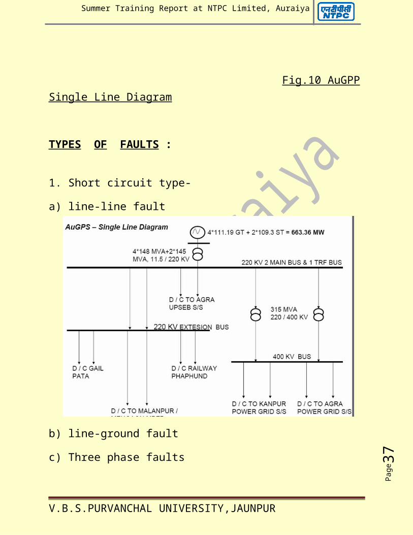
SWITCHYARD-It is a medium for exchange of power from sourceto load or from one source to another.It consists of switching equipment, measurement,protection and control equipment required for power generation and utilization
Components
V.B.S.PURVANCHAL UNIVERSITY,JAUNPUR
Page36
Summer Training Report at NTPC Limited, Auraiya
- Circuit breaker (CB)
- Isolator
- Earth Switch
- Current Transformers (CT)
- Capacitive Voltage Transformers (CVT
- Lightening Arrester (LA)
- WAVE TRAP
- Potential Transformers (PT)
- Line matching unit (LMU)
- Lightening Mast (LA)
V.B.S.PURVANCHAL UNIVERSITY,JAUNPUR
Page37
Summer Training Report at NTPC Limited, Auraiya
Fig.10 AuGPPSingle Line Diagram
TYPES OF FAULTS :
1. Short circuit type-
a) line-line fault
b) line-ground fault
c) Three phase faults
V.B.S.PURVANCHAL UNIVERSITY,JAUNPUR
Page38
Summer Training Report at NTPC Limited, Auraiya
2. Open conductor type-
a) One open conductor
b) Two open conductors
Power system protection key aspects:
1. Reliability- Probability that the system willfunction correctly when required acting (for afault in its zone)
2. Security/Stability- Refrain from unwantedoperation in the absence of fault or faultoutside its zone
3. Sensitivity- Ability of the system to detectthe threshold value of an abnormal condition toinitiate protective action.
4. Protection zones- Regions of primarysensitivity
5. Coordination- Determination of gradedsettings to achieve selectivity
V.B.S.PURVANCHAL UNIVERSITY,JAUNPUR
Page39
Summer Training Report at NTPC Limited, Auraiya
6. Primary Relays- Relays with in a particularzone that should operate for prescribedabnormalities with in that zone
7. Back up Relays- Relays with in a particularzone that should operate for prescribedabnormalities with in that zone
Distance protection:
The impedance relays also called distance relaysare employed to provide protection totransmission lines.
They are comparatively simple to apply, operatewith extremely high speed, and both primary andbackup protection features are inherent in them.
The impedance relay is made to respond to theimpedance between the relay location and thepoint where fault is incident
The impedance is proportional to the distance tothe fault, hence the name 'distance relay'.
Types of distance relays:
1. Impedance relay
V.B.S.PURVANCHAL UNIVERSITY,JAUNPUR
Page40
Summer Training Report at NTPC Limited, Auraiya
2. Reactance relay
3. Mho relay
4. Modified impedance relay
Applications of distance relays:
1. Since the distance relays are fed from thesecondary of line CTs and bus PTs/line CVTs, theline parameters are to be converted intosecondary values to set the relay as perrequirements
2. Z sec = Z primary/Impedance ratio
(Where Impedance ratio =P.T.Ratio/C.T.Ratio)
3. For the lines, the impedance in Ohms per KMis approximately as under:
---------------------------------------------------------------------------------------
KV Z1 (= Z2) Line Angle
---------------------------------------------------------------------------------------
132 KV 0.4 60 to70Deg.
V.B.S.PURVANCHAL UNIVERSITY,JAUNPUR
Page41
Summer Training Report at NTPC Limited, Auraiya
220 KV 0.4 70 to80Deg.
400 KV 0.3 80 to85Deg.
Other protections:
Local Breaker Back up protection (LBB)-
• Backup in case of stuck breaker condition
• Initiated from all the protections thattrip the breaker
• Acts if the AC current in the circuit ismore than a set limit, for a set timedelay after the protections acted
• Trips all the breakers connected to thatbus and the remote end breaker to stopthe fault current
• Typical setting:
• Current 20% of In for all bays other thangen bays, 5 % For gen bays
• Time delay 200 msec
Open jumper protection:
• Detects the negative sequence current
V.B.S.PURVANCHAL UNIVERSITY,JAUNPUR
Page42
Summer Training Report at NTPC Limited, Auraiya
• Alarm/ Trip issued when I2 exceeds a setlimit and after a set time delay
• Time delay shall be greater than thesingle phase dead time of A/R and aconsiderable margin
Over voltage
• Two stage o/v protection
• Stage –1 : 120 % 2-5 sec
• Stage –2 : 140 % instantaneous
Fuse failure protection
• Detects the sec fuse failure of VT andblocks the voltage operated protections
• In modern numerical distance relays, VTfuse failure switch on an O/C feature
Additional features in distance schemes:
1. Power Swing blocking relay
2. VT fuse failure relay.
V.B.S.PURVANCHAL UNIVERSITY,JAUNPUR
Page43
Summer Training Report at NTPC Limited, Auraiya
3. Switch onto fault relay
4. Fault locator
5. Auto- reclosing scheme.
6. Carrier communication scheme
V.B.S.PURVANCHAL UNIVERSITY,JAUNPUR
Related Documents