This manual has been provided to assist you with lift installation and operation. For further assistance please contact your authorized Harmar dealer or Harmar’s Technical Service department. Tel: 866-378-6648 Fax: 816-537-0641 Commercial Platform Lift HIGHLANDER CPL400 CPL600 CPL800 CPL1000 CPL1200 CPL1400 CPLP400 TG400 P/N: 630-00042 Rev D

Welcome message from author
This document is posted to help you gain knowledge. Please leave a comment to let me know what you think about it! Share it to your friends and learn new things together.
Transcript
This manual has been provided to assist you with lift installation and operation. For further assistance please contact your authorized Harmar dealer or Harmar’s Technical Service department.
Tel: 866-378-6648 Fax: 816-537-0641
Commercial Platform LiftH I G H L A N D E R
CPL400 CPL600 CPL800 CPL1000 CPL1200 CPL1400 CPLP400TG400
P/N: 630-00042 Rev D
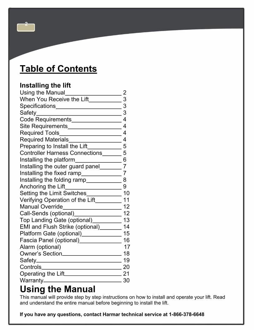
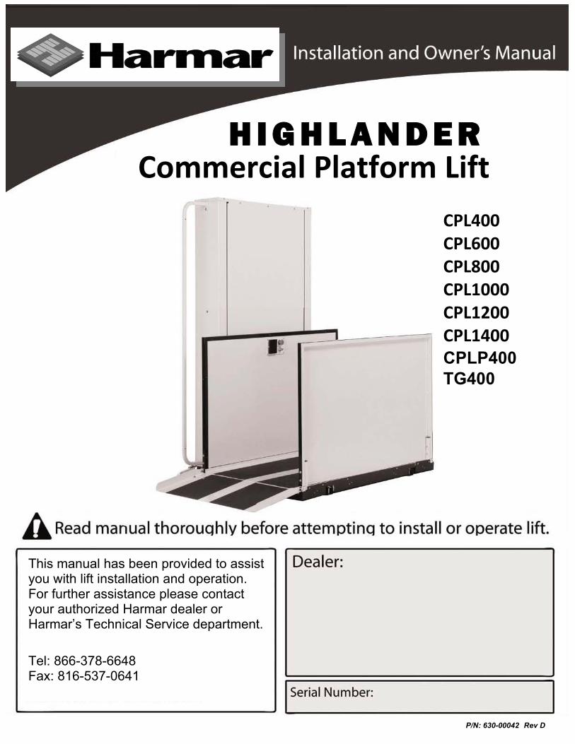
Table of Contents Installing the lift Using the Manual 2 When You Receive the Lift 3 Specifications 3 Safety 3 Code Requirements 4 Site Requirements 4 Required Tools 4 Required Materials 4 Preparing to Install the Lift 5 Controller Harness Connections 5 Installing the platform 6 Installing the outer guard panel 7 Installing the fixed ramp 7 Installing the folding ramp 8 Anchoring the Lift 9 Setting the Limit Switches 10 Verifying Operation of the Lift 11 Manual Override 12 Call-Sends (optional) 12 Top Landing Gate (optional) 13 EMI and Flush Strike (optional) 14 Platform Gate (optional) 15 Fascia Panel (optional) 16Alarm (optional) 17Owner’s Section 18 Safety 19 Controls 20 Operating the Lift 21 Warranty 30
Using the Manual This manual will provide step by step instructions on how to install and operate your lift. Read and understand the entire manual before beginning to install the lift.
If you have any questions, contact Harmar technical service at 1-866-378-6648
2
joe.brock
Line
When You Receive the Lift • Check the lift for shipping damage. If you see any damage contact the freight carrier to file a damage
claim.
• Verify the products match that described on the packing list attached to the exterior packaging.
• Verify the contents of the package match that shown below to the right.
Specifications Payload Capacity 750 lbs
Vertical Travel 54” – 171”
Height 77” – 197”
Foot Print VARIES
Platform Size 36” x 54” / 36” x 60” / 42” x 60”
Input Voltage 115vac - 20a
Control Voltage 24vac or 24vdc
Platform Speed 10 ft/min
Motor 1/2hp-90vdc or 1/2hp-24vdc
Safety • Read all instructions in this manual before installing or operating the lift.
• Do not exceed the maximum payload capacity of 750 lbs.
• Do not ride on the lift until it is anchored in place.
• This product is designed only for lifting people and wheel chairs. Do not use it for any other purpose.
• Always wear eye protection while installing or servicing this product.
• Always disconnect this product from the electrical source before servicing it.
•
• Do not wear loose clothing or jewelry when working on this product.
• Do not disable any safety equipment or switches supplied with this lift.
• Stay away from all drive train components while the lift is operating.
Only use the fasteners supplied with this lift.
3
Code Requirements Your lift has been designed to meet ASME A18.1 section 2 and CSA B44/ASME A17.5, with the addition of certain options. Code requirements for Vertical Platform lifts vary depending on location. It is the installers responsibility to contact their local code enforcement office and determine all of the regulations they are subject to. You must do this before installing the Vertical Platform Lift.
Site Requirements • The lift will require a 115vac 20amp grounded circuit.
• Outdoor Installations will require a GFI protected circuit.
• Only install the lift on a 4” thick , level 3,500 psi reinforced concrete slab.
• Foot Print varies depending on platform size and options.
Required tools • 1/2" Hammer Drill
• 3/8" Masonry Drill Bit
• Appliance Dolly
• Hammer
• Level
• Measuring Tape
• Socket Wrench Set
Required materials • 4 Floor anchorsHarmar recommends securing the lift using our Anchor Kit. If you purchase you ownfloor anchors they must use 3/8” bolts and have a minimum tensile strength of 6000 LBS.
4
Preparing to Install the Lift
Final Site Inspection Verify the surface the lift will mount to is smooth and level. This surface must be made from 3,500 psi reinforced concrete with a minimum thickness of 4”. Verify that there is enough space for the lifts foot print. Be sure to include space neccesary for platform.
Caution: Verify that the running clearance around the lift complies with any codes for your area.
• The horizontal gap between the edge of the platform and the upper landing must no less than 3/8”and no greater than 3/4”.
• The horizontal gap between the guard panel and any wall or barrier must be no less than 2” andno greater than 3”.
• Verify that sufficient head room exists above the lift. The lift will require 6’ 8” of clearance abovethe platform floor when the lift is at the upper landing.
Warning: The area between the floor where the lift is mounted and the top landing must be covered by a smooth vertical fascia. This is to to eliminate any pinch points between the platform and landing.
Connecting to Electricity The lift will require a 115 VAC 20 amp grounded electrical circuit. Depending on local codes, this connection may need to be routed in electrical conduit and hard-wired.
Warning: Do not ride on the lift until it has been anchored in place.
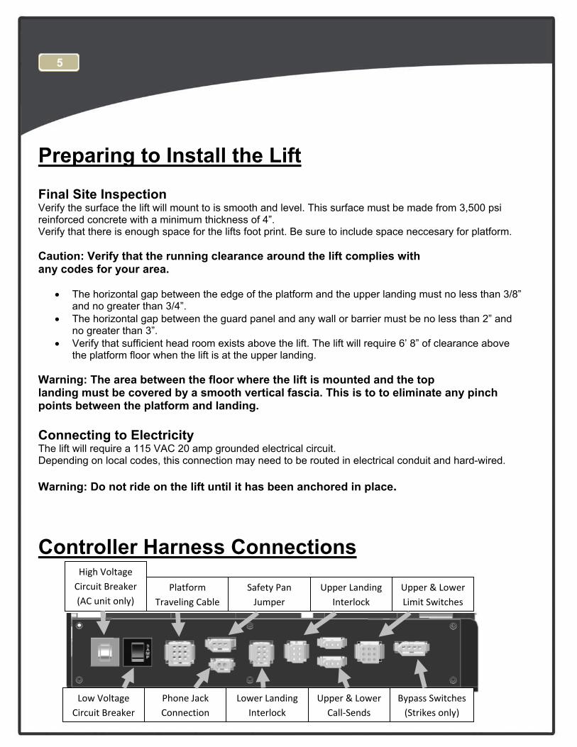
Controller Harness Connections
5
High Voltage Circuit Breaker (AC unit only)
Low Voltage Circuit Breaker
Platform Traveling Cable
Phone Jack Connection
Safety Pan Jumper
Upper Landing Interlock
Lower Landing Interlock
Upper & Lower Call‐Sends
Upper & Lower Limit Switches
Bypass Switches (Strikes only)
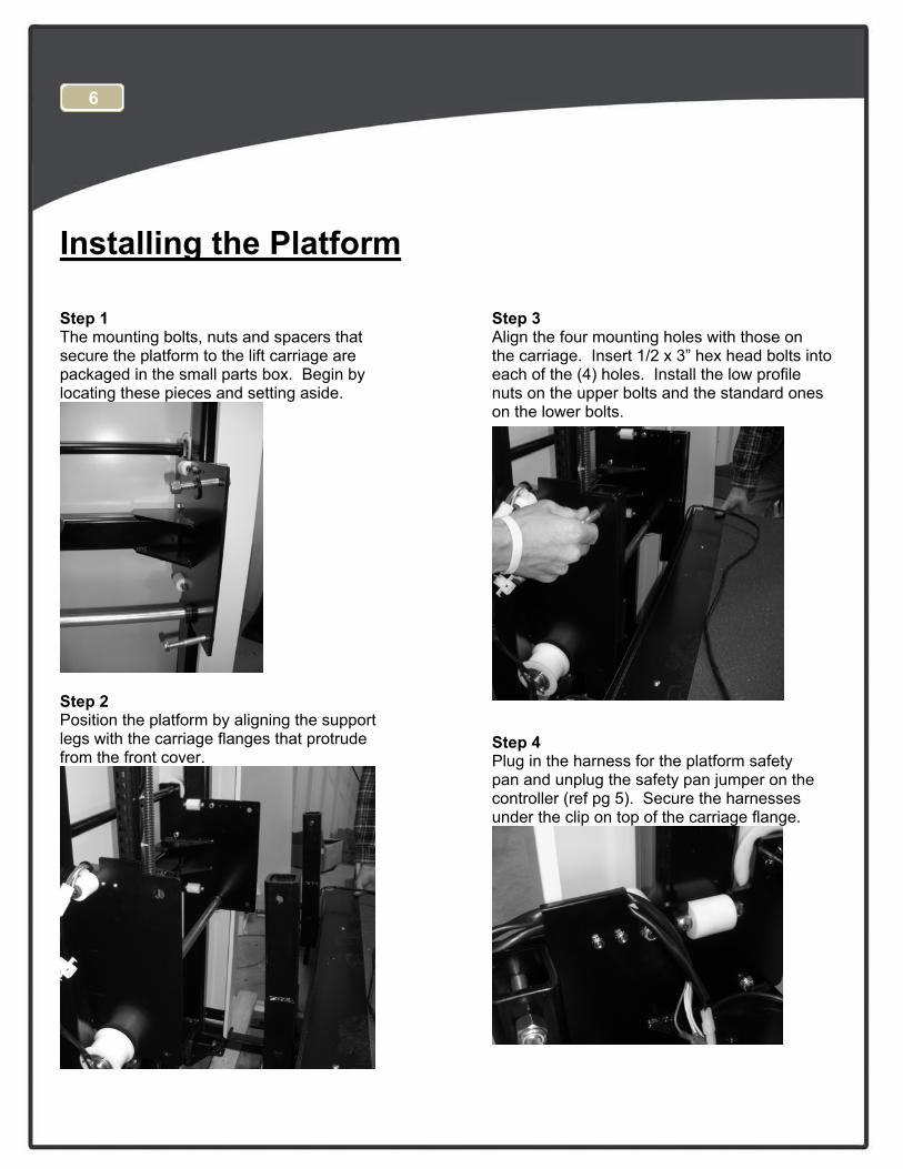
Installing the Platform
Step 1 The mounting bolts, nuts and spacers that secure the platform to the lift carriage are packaged in the small parts box. Begin by locating these pieces and setting aside.
Step 2 Position the platform by aligning the support legs with the carriage flanges that protrude from the front cover.
Step 3 Align the four mounting holes with those on the carriage. Insert 1/2 x 3” hex head bolts into each of the (4) holes. Install the low profile nuts on the upper bolts and the standard ones on the lower bolts. .
Step 4 Plug in the harness for the platform safety pan and unplug the safety pan jumper on the controller (ref pg 5). Secure the harnesses under the clip on top of the carriage flange.
6
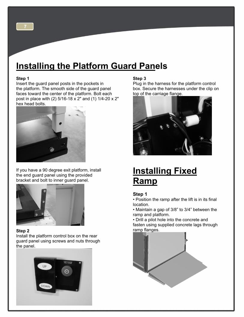
Installing the Platform Guard Panels Step 1 Insert the guard panel posts in the pockets in the platform. The smooth side of the guard panel faces toward the center of the platform. Bolt each post in place with (2) 5/16-18 x 2" and (1) 1/4-20 x 2"hex head bolts.
If you have a 90 degree exit platform, install the end guard panel using the provided bracket and bolt to inner guard panel.
Step 2 Install the platform control box on the rear guard panel using screws and nuts through the panel.
Step 3 Plug in the harness for the platform control box. Secure the harnesses under the clip on top of the carriage flange.
Installing Fixed Ramp Step 1 • Position the ramp after the lift is in its finallocation.• Maintain a gap of 3/8” to 3/4” between theramp and platform.• Drill a pilot hole into the concrete andfasten using supplied concrete lags throughramp flanges.
7
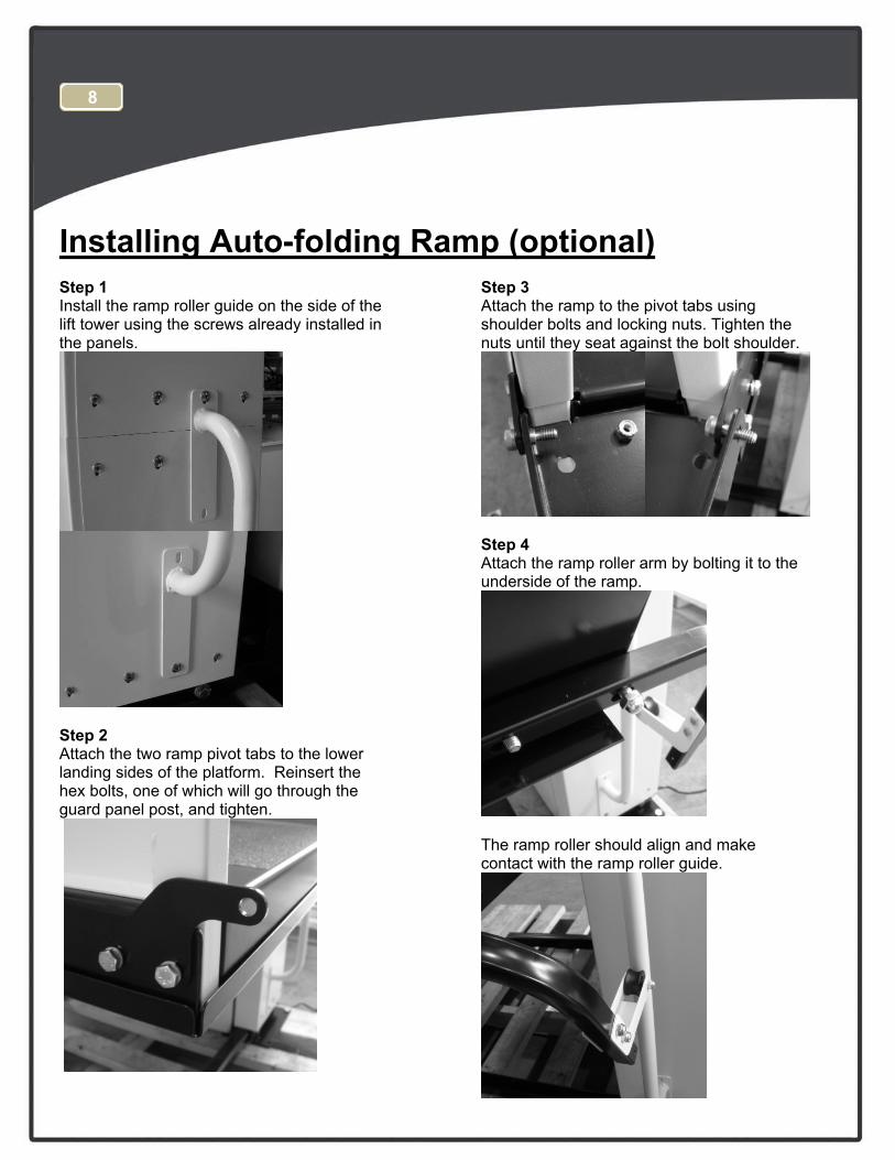
Installing Auto-folding Ramp (optional) Step 1 Install the ramp roller guide on the side of the lift tower using the screws already installed in the panels.
Step 2 Attach the two ramp pivot tabs to the lower landing sides of the platform. Reinsert the hex bolts, one of which will go through the guard panel post, and tighten.
Step 3 Attach the ramp to the pivot tabs using shoulder bolts and locking nuts. Tighten the nuts until they seat against the bolt shoulder.
Step 4 Attach the ramp roller arm by bolting it to the underside of the ramp.
The ramp roller should align and make contact with the ramp roller guide.
8
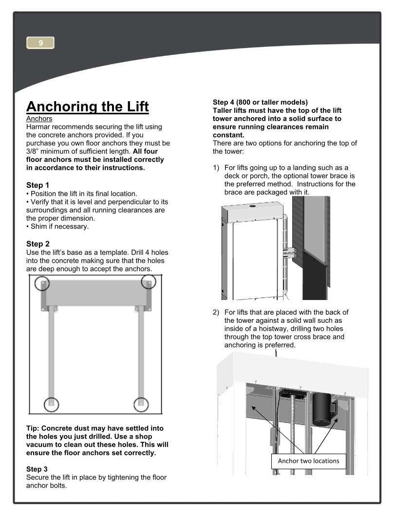
Anchoring the Lift Anchors Harmar recommends securing the lift using the concrete anchors provided. If you purchase you own floor anchors they must be 3/8” minimum of sufficient length. All four floor anchors must be installed correctly in accordance to their instructions.
Step 1 • Position the lift in its final location.• Verify that it is level and perpendicular to itssurroundings and all running clearances arethe proper dimension.• Shim if necessary.
Step 2 Use the lift’s base as a template. Drill 4 holes into the concrete making sure that the holes are deep enough to accept the anchors.
Tip: Concrete dust may have settled into the holes you just drilled. Use a shop vacuum to clean out these holes. This will ensure the floor anchors set correctly.
Step 3 Secure the lift in place by tightening the floor anchor bolts.
Step 4 (800 or taller models) Taller lifts must have the top of the lift tower anchored into a solid surface to ensure running clearances remain constant. There are two options for anchoring the top of the tower:
1) For lifts going up to a landing such as adeck or porch, the optional tower brace isthe preferred method. Instructions for thebrace are packaged with it.
2) For lifts that are placed with the back ofthe tower against a solid wall such asinside of a hoistway, drilling two holesthrough the top tower cross brace andanchoring is preferred.
9
Anchor two locations
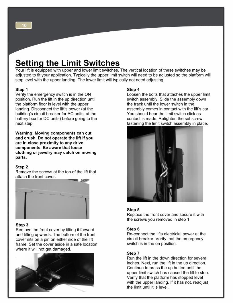
Setting the Limit Switches Your lift is equipped with upper and lower limit switches. The vertical location of these switches may be adjusted to fit your application. Typically the upper limit switch will need to be adjusted so the platform will stop level with the upper landing. The lower limit will typically not need adjusting.
Step 1 Verify the emergency switch is in the ON position. Run the lift in the up direction until the platform floor is level with the upper landing. Disconnect the lift’s power (at the building’s circuit breaker for AC units, at the battery box for DC units) before going to the next step.
Warning: Moving components can cut and crush. Do not operate the lift if you are in close proximity to any drive components. Be aware that loose clothing or jewelry may catch on moving parts.
Step 2 Remove the screws at the top of the lift that attach the front cover.
Step 3 Remove the front cover by tilting it forward and lifting upwards. The bottom of the front cover sits on a pin on either side of the lift frame. Set the cover aside in a safe location where it will not get damaged.
Step 4 Loosen the bolts that attaches the upper limit switch assembly. Slide the assembly down the track until the lower switch in the assembly comes in contact with the lift’s car. You should hear the limit switch click as contact is made. Retighten the set screw fastening the limit switch assembly in place.
Step 5 Replace the front cover and secure it with the screws you removed in step 1.
Step 6 Re-connect the lifts electricial power at the circuit breaker. Verify that the emergency switch is in the on position.
Step 7 Run the lift in the down direction for several inches. Next, run the lift in the up direction. Continue to press the up button until the upper limit switch has caused the lift to stop. Verify that the platform has stopped level with the upper landing. If it has not, readjust the limit until it is level.
10
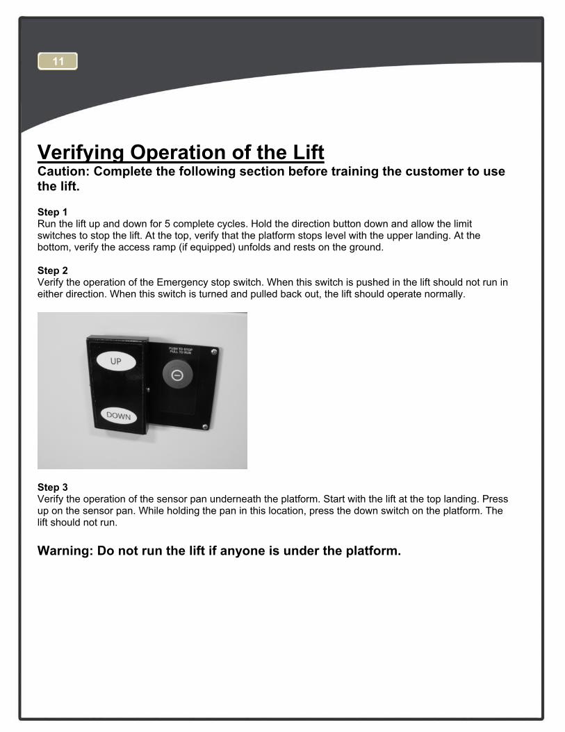
Verifying Operation of the Lift Caution: Complete the following section before training the customer to use the lift.
Step 1 Run the lift up and down for 5 complete cycles. Hold the direction button down and allow the limit switches to stop the lift. At the top, verify that the platform stops level with the upper landing. At the bottom, verify the access ramp (if equipped) unfolds and rests on the ground.
Step 2 Verify the operation of the Emergency stop switch. When this switch is pushed in the lift should not run in either direction. When this switch is turned and pulled back out, the lift should operate normally.
Step 3 Verify the operation of the sensor pan underneath the platform. Start with the lift at the top landing. Press up on the sensor pan. While holding the pan in this location, press the down switch on the platform. The lift should not run.
Warning: Do not run the lift if anyone is under the platform.
11
Manual Override Your lift is equipped with a manual handcrank, to be used in the case of a power failure.
Step 1 Before using the manual handcrank verify that it’s use is required. Check that the emergency stop switch is pulled out. Check that the electrical cord is connected to the supply. Also check that the buildings circuit breaker has not tripped. Try to run the lift by pushing both the up and down buttons. If the lift still will not run, complete the following steps:
Step 2 Disconnect the power from the lift. Warning: Do not service or operate the manual handcrank while the lift is connected to electricity.
Step 3 Remove the screws and remove the top cap at the top of the tower.
Step 4 Insert the manual handcrank into the opening on the top of the brake assembly. It may be neccesary to slightly rotate the handcrank until it fully seats down on the hex portion of the brake. Rotate the crank to raise or lower the platform.
Warning: Never operate the lift while the manual override crank is inserted into the lift.
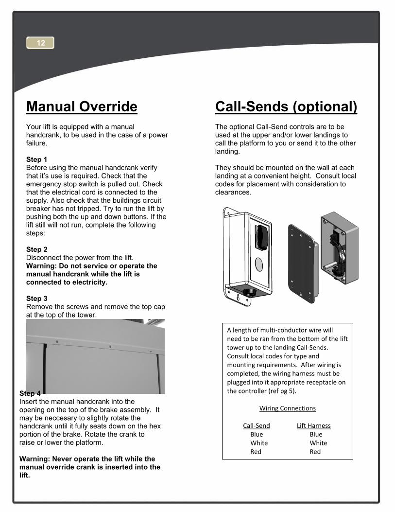
Call-Sends (optional) The optional Call-Send controls are to be used at the upper and/or lower landings to call the platform to you or send it to the other landing.
They should be mounted on the wall at each landing at a convenient height. Consult local codes for placement with consideration to clearances.
12
A length of multi‐conductor wire will need to be ran from the bottom of the lift tower up to the landing Call‐Sends. Consult local codes for type and mounting requirements. After wiring is completed, the wiring harness must be plugged into it appropriate receptacle on the controller (ref pg 5).
Wiring Connections
Call‐Send Lift Harness Blue Blue White White Red Red
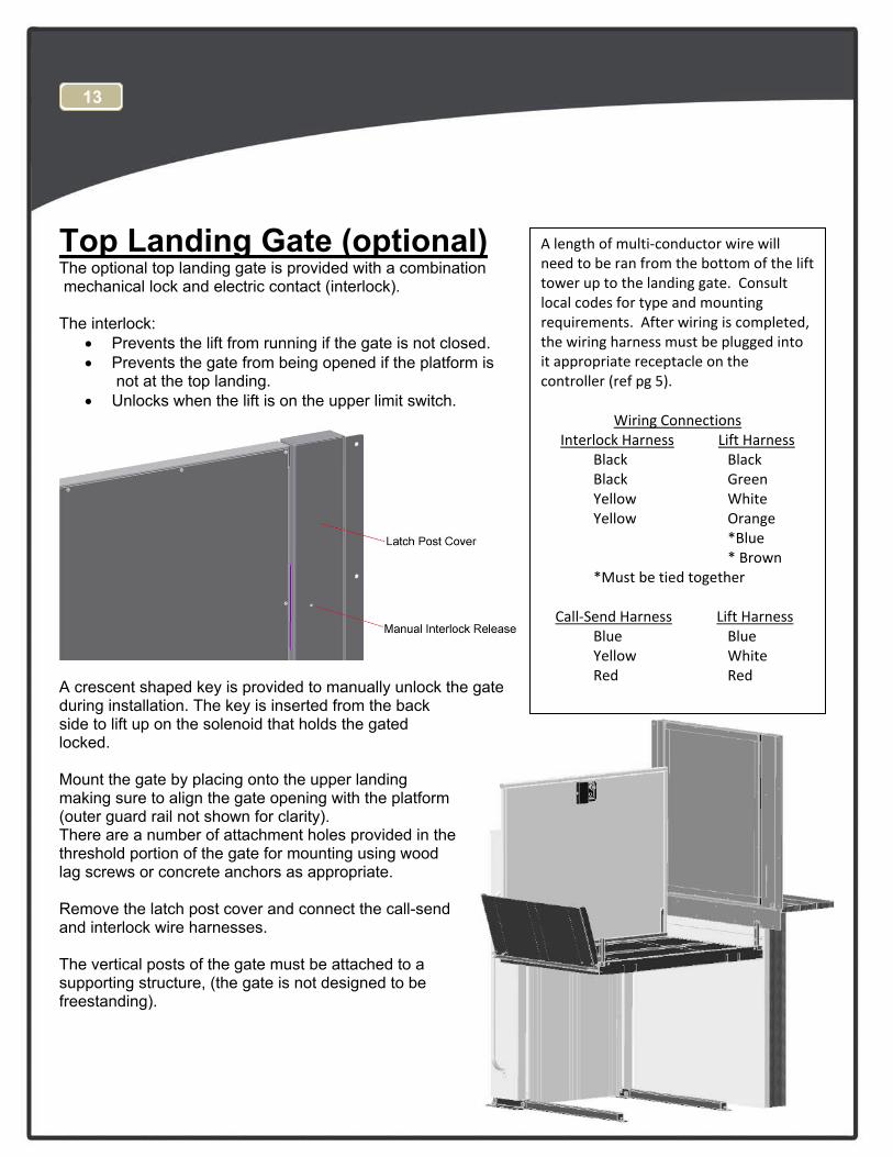
Top Landing Gate (optional) The optional top landing gate is provided with a combination mechanical lock and electric contact (interlock).
The interlock: • Prevents the lift from running if the gate is not closed.• Prevents the gate from being opened if the platform is
not at the top landing.• Unlocks when the lift is on the upper limit switch.
A crescent shaped key is provided to manually unlock the gate during installation. The key is inserted from the back side to lift up on the solenoid that holds the gated locked.
Mount the gate by placing onto the upper landing making sure to align the gate opening with the platform (outer guard rail not shown for clarity). There are a number of attachment holes provided in the threshold portion of the gate for mounting using wood lag screws or concrete anchors as appropriate.
Remove the latch post cover and connect the call-send and interlock wire harnesses.
The vertical posts of the gate must be attached to a supporting structure, (the gate is not designed to be freestanding).
13
A length of multi‐conductor wire will need to be ran from the bottom of the lift tower up to the landing gate. Consult local codes for type and mounting requirements. After wiring is completed, the wiring harness must be plugged into it appropriate receptacle on the controller (ref pg 5).
Wiring Connections Interlock Harness Lift Harness
Black Black Black Green Yellow White Yellow Orange
*Blue* Brown
*Must be tied together
Call‐Send Harness Lift Harness Blue Blue Yellow White Red Red
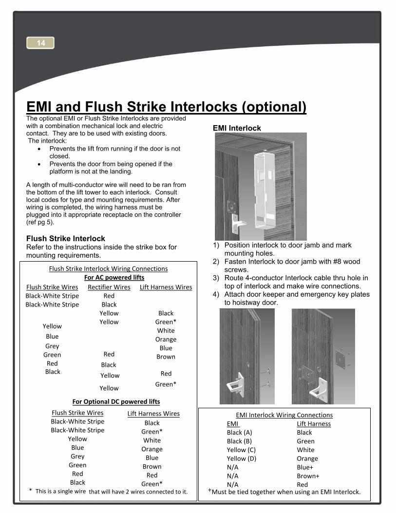
EMI and Flush Strike Interlocks (optional) The optional EMI or Flush Strike Interlocks are provided with a combination mechanical lock and electric contact. They are to be used with existing doors. The interlock:
• Prevents the lift from running if the door is notclosed.
• Prevents the door from being opened if theplatform is not at the landing.
A length of multi-conductor wire will need to be ran from the bottom of the lift tower to each interlock. Consult local codes for type and mounting requirements. After wiring is completed, the wiring harness must be plugged into it appropriate receptacle on the controller (ref pg 5).
Flush Strike Interlock Refer to the instructions inside the strike box for mounting requirements.
EMI Interlock
1) Position interlock to door jamb and markmounting holes.
2) Fasten Interlock to door jamb with #8 woodscrews.
3) Route 4-conductor Interlock cable thru hole intop of interlock and make wire connections.
4) Attach door keeper and emergency key platesto hoistway door.
14
EMI Interlock Wiring Connections EMI Lift Harness Black (A) Black Black (B) Green Yellow (C) White Yellow (D) Orange N/A Blue+ N/A Brown+ N/A Red
+Must be tied together when using an EMI Interlock.
Flush Strike Interlock Wiring Connections For AC powered lifts
Flush Strike Wires Rectifier Wires Lift Harness Wires Black‐White Stripe Red Black‐White Stripe Black
Yellow Black Yellow Green*
Yellow White
Blue Orange Grey Blue Green Brown Red
Red
Black Black
Yellow Red
Yellow Green*
For Optional DC powered lifts
Lift Harness Wires Flush Strike Wires Black‐White Stripe Black‐White Stripe
Yellow Blue Grey Green Red Black
Black Green* White Orange Blue Brown Red
Green* * This is a single wire that will have 2 wires connected to it.
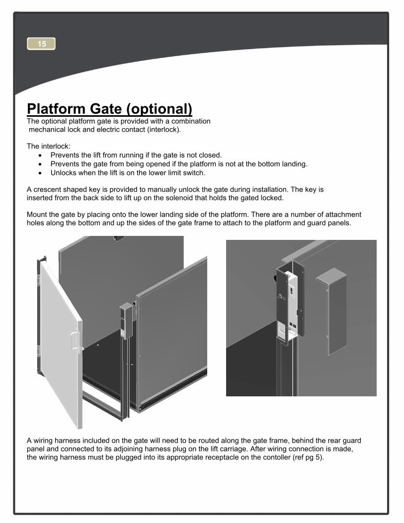
Platform Gate (optional) The optional platform gate is provided with a combination mechanical lock and electric contact (interlock).
The interlock: • Prevents the lift from running if the gate is not closed.• Prevents the gate from being opened if the platform is not at the bottom landing.• Unlocks when the lift is on the lower limit switch.
A crescent shaped key is provided to manually unlock the gate during installation. The key is inserted from the back side to lift up on the solenoid that holds the gated locked.
Mount the gate by placing onto the lower landing side of the platform. There are a number of attachment holes along the bottom and up the sides of the gate frame to attach to the platform and guard panels.
A wiring harness included on the gate will need to be routed along the gate frame, behind the rear guard panel and connected to its adjoining harness plug on the lift carriage. After wiring connection is made, the wiring harness must be plugged into its appropriate receptacle on the contoller (ref pg 5).
15
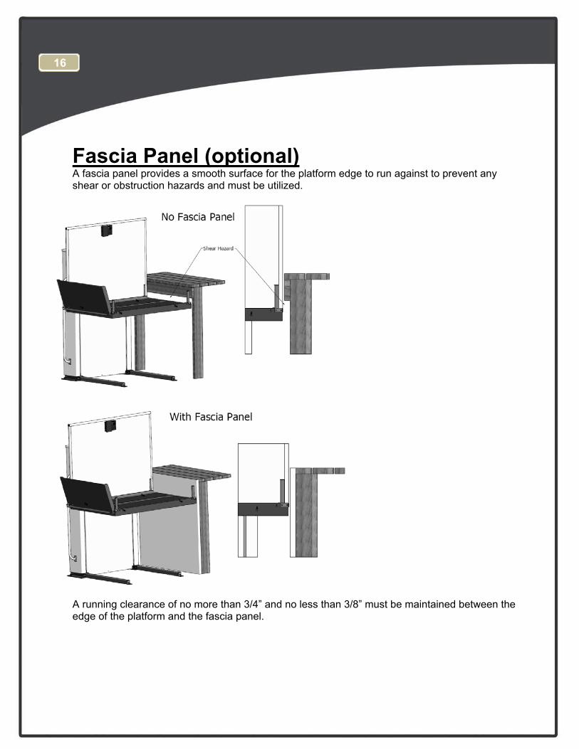
Fascia Panel (optional) A fascia panel provides a smooth surface for the platform edge to run against to prevent any shear or obstruction hazards and must be utilized.
A running clearance of no more than 3/4” and no less than 3/8” must be maintained between the edge of the platform and the fascia panel.
16
Platform Control with Optional E-Stop Alarm
17
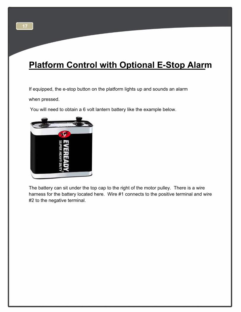
If equipped, the e-stop button on the platform lights up and sounds an alarm
when pressed.
You will need to obtain a 6 volt lantern battery like the example below.
The battery can sit under the top cap to the right of the motor pulley. There is a wire harness for the battery located here. Wire #1 connects to the positive terminal and wire #2 to the negative terminal.
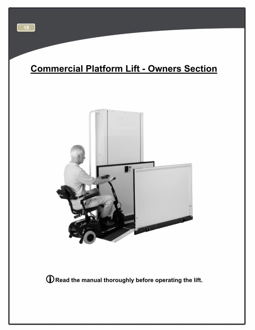
Commercial Platform Lift - Owners Section
Read the manual thoroughly before operating the lift.
18
Congratulations on the purchase of your Harmar Vertical Platform Lift. This lift has been engineered to provide trouble free service for many, many years. Please read this manual completely before operating your lift.
Safety • Do not exceed the maximum payload capacity of 750 lbs.
• Do not ride on the lift until it is anchored in place.
• This product is designed only for lifting people and wheel chairs. Do not use it for any other purpose.
• Make sure any obstructions are cleared from underneath the platform area before use.
• Make sure both the passenger and wheelchair are completely on to the platform before using.
• Do not disable any safety equipment or switches supplied with this lift.
• Do not attempt to service the lift yourself. Contact your Harmar dealer for assistance.
• Do not allow children to operate or play around the lift.
• Read all instructions in this manual before installing or operation the lift.
19
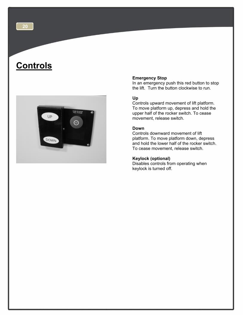
Controls Emergency Stop In an emergency push this red button to stop the lift. Turn the button clockwise to run.
Up Controls upward movement of lift platform. To move platform up, depress and hold the upper half of the rocker switch. To cease movement, release switch.
Down Controls downward movement of lift platform. To move platform down, depress and hold the lower half of the rocker switch. To cease movement, release switch.
Keylock (optional) Disables controls from operating when keylock is turned off.
20
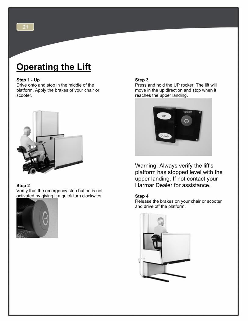
Operating the Lift Step 1 - Up Drive onto and stop in the middle of the platform. Apply the brakes of your chair or scooter.
Step 2 Verify that the emergency stop button is not activated by giving it a quick turn clockwies.
Step 3 Press and hold the UP rocker. The lift will move in the up direction and stop when it reaches the upper landing.
Warning: Always verify the lift’s platform has stopped level with the upper landing. If not contact your Harmar Dealer for assistance.
Step 4 Release the brakes on your chair or scooter and drive off the platform.
21
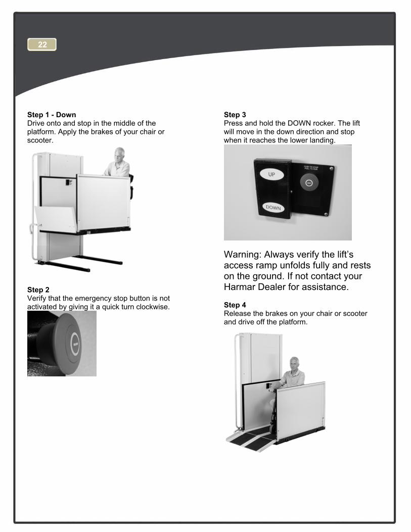
Step 1 - Down Drive onto and stop in the middle of the platform. Apply the brakes of your chair or scooter.
Step 2 Verify that the emergency stop button is not activated by giving it a quick turn clockwise.
Step 3 Press and hold the DOWN rocker. The lift will move in the down direction and stop when it reaches the lower landing.
Warning: Always verify the lift’s access ramp unfolds fully and rests on the ground. If not contact your Harmar Dealer for assistance.
Step 4 Release the brakes on your chair or scooter and drive off the platform.
22
1 1
2 2
3 3
4 4
AA
BB
90 V
DC
Moto
r
Up
Top Lm
t
UP
A1
A2
Do
wn
DN
A1
A2
VA
CV
AC
24
Top
In
te
rlo
ck
Solen
oid
Final Lm
t
CN
C
110
Key
Sw
itch
SA
F
A1
A2
Em
erge
ncy
Stop
SA
F
21
Safety P
an S
witch
es
CN
CC
NC
CN
CC
NC
110 VAC
2
3
8
4
10
11
1
12
13
DN
22
21
UP
22
21
15 A
mp
C.B
.
3 A
mp
C.B
.
Top
Gate
Close
d
6
7
CN
O
Btm
Gate
Closed
CN
O
CN
C
Btm
Lm
t
Btm
In
te
rlo
ck
Solen
oid
9
Btm
D
oor
Lo
cked
Bypass
Top D
oor
Locked
Byp
ass
5
+ -
6V
DC
UP
34
Brake
RED
BLK
Belt M
onitor
CN
O
CN
C
NO
NO
14
15
16
L1
L2
G
4T
erm
inal S
trip C
onnection
Sw
itch - N
.C
.
Sw
itch - N
.O
. held closed
Push B
utton
Contact - N
.O
.
Contact - N
.C
.
Circuit B
reaker
Leg
en
d:
Optional E
quipm
ent
Call S
end
NO
NO
NO
NO
C
C
C C
UP
21
DN
12
-15V
Sig
+15V
L2
L1
90V
DC
O
utput
12A
Rege
n D
rive
Tach
Com
EN
DN
34
+
-
~~
90 V
DC
17 6
12
13
Optional W
irele
ss C
all-S
end
s
9
8
NO
CO
M
A1
A2
NO
C
NO
C
NO
CO
M
A1
A2
Op
tion
al A
uto D
oo
r
Op
ener R
elays
To
p
Btm
La
ndin
g
Sw
itch
La
nd
in
g
Sw
itch
To
D
oo
r
Op
en
er
To
D
oo
r
Op
en
er
12
13
CN
CC
NC
Pit S
witch
CN
C
(O
ption
al)
joe.brock
Typewritten Text
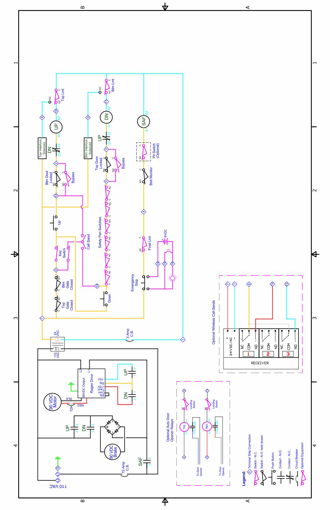
SCHEMATIC, CPL AC, 2-STOP 44231 REV E
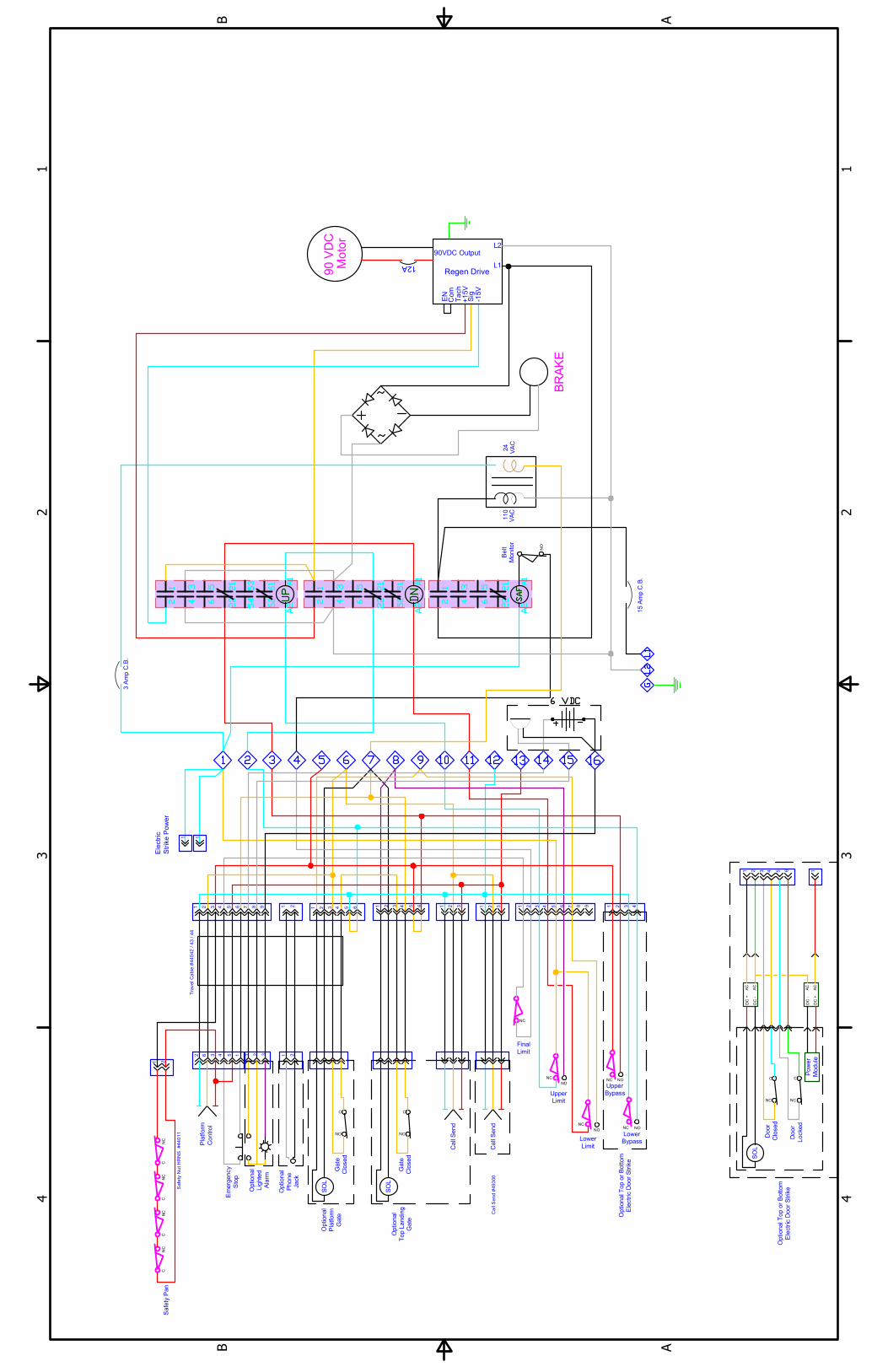
1 1
2 2
3 3
4 4
AA
BB
VA
C
VA
C
24
110
15 A
mp C
.B
.
3 A
mp C
.B
.
90 V
DC
Motor
BR
AK
E
Call S
end
NC
NC
NO
NC
Em
ergency
Stop
Platform
Control
CN
CC
NC
CN
CC
NC
Safety P
an
Lower
Limit
Upper
Limit
Final
Limit
Travel C
able #
44
042
/ 4
3 / 44
Safe
ty N
ut H
RN
S #
44
011
Ca
ll S
en
d #
49
300
NO
C
NO
SO
L
Gate
Closed
C
NO
SO
L
Gate
Closed
Optional
Phone
Jack
Optional
Platform
Gate
Optional
Top Landing
Gate
Optional
Lighted
Alarm
Call S
end
NC NO
NC
Lower
Bypass
Upper
Bypass
NO
Optional T
op or B
ottom
Electric D
oor S
trike
Optional T
op or B
ottom
Electric D
oor S
trike
1
2 3 4
6
7
8 9
5
1
2
1
2 3 4
6
5
1
2 3
4
6
5
1
2
3 4
6
7
8 9
5
1
2
3 4
6
5
1
2 3
1
2 3 1
2 3 4
1
2
12
3 4
6
5
1
2 3
1
2
-1
5V
Sig
+1
5V
L2
L1
90VDC Output
12A
Regen Drive
Ta
ch
Com
EN
NO
Belt
Monitor
C
NC
SO
L
Door
Closed
Door
Locked
C
NC
Pow
er
Module
1
AC
AC
DC
+
DC
-
AC
AC
DC
-
DC
+
1 1
Ele
ctric
Strike
P
ow
er
joe.brock
Typewritten Text
WIRING DIAGRAM, CPL AC, 2-STOP 44231 REV D
1 1
2 2
3 3
4 4
AA
BB
90 V
DC
Mo
tor
Up
To
p L
mt
UP
A1
A2
Dow
n
DN
A1
A2
VA
CV
AC
24
Top
In
te
rlock
So
le
no
id
Fin
al L
mt
CN
C
11
0
Ke
y
Sw
itch
SA
F
A1
A2
Em
erge
ncy
Stop
SA
F
21
Sa
fety P
an
S
witch
es
CN
CC
NC
CN
CC
NC
110 VAC
2
3
8
4
10
11
1
12
13
DN
22
21
UP
22
21
15 A
mp
C.B
.
3 A
mp
C.B
.
To
p
Ga
te
Clo
sed
6
7
CN
O
Btm
Ga
te
Clo
sed
CN
O
CN
C
Btm
L
mt
Btm
In
te
rlo
ck
So
le
no
id
9
Btm
D
oor
Locke
d
Bypass
To
p D
oor
Locke
d
Bypa
ss
5
+ -
6V
DC
UP
34
Brake
RED
BLK
Be
lt M
onitor
CN
O
CN
C
NO
NO
L1
L2
G
4T
erm
ina
l S
trip
C
on
ne
ction
Sw
itch - N
.C
.
Sw
itch - N
.O
. he
ld clo
se
d
Pu
sh B
utto
n
Co
nta
ct - N
.O
.
Co
nta
ct - N
.C
.
Circuit B
rea
ke
r
Le
gen
d:
Op
tio
na
l E
qu
ipm
en
t
Call S
ta
tion
NO
NO
NO
NO
C
C
C
C
UP
21
DN
12
-15V
Sig
+15V
L2
L1
90V
DC
O
utpu
t
12A
Reg
en
D
rive
Tach
Com
EN
DN
34
+
-
~~
90 V
DC
Mid
14
Mid
In
te
rlo
ck
So
le
no
id
15
Mid D
oor
Locked
Bypa
ss
NO
NO
C
C
Mid
Gate
Close
d
CN
O
16
Up
Mid
Dow
n
13
12
6 6 6
4 3 2 1
8 7 6 5
Mid
L
mt
9
8
1
NO
CO
M
A1
A2
NO
C
NO
C
NO
C
Mid
C
all
Sta
tion
NO
CO
M
A1
A2
NO
CO
M
A1
A2
Doo
r O
pen
er
Rela
ys
To
p
Btm
Mid
Land
in
g
Sw
itch
Lan
ding
Sw
itch
Land
in
g
Sw
itch
To
D
oo
r
Op
en
er
To
D
oor
Op
en
er
To D
oor
Ope
ner
12
13
UP
62
61
DN
62
61
CN
CC
NC
CN
C
Pit S
witch
(O
ption
al)
C
joe.brock
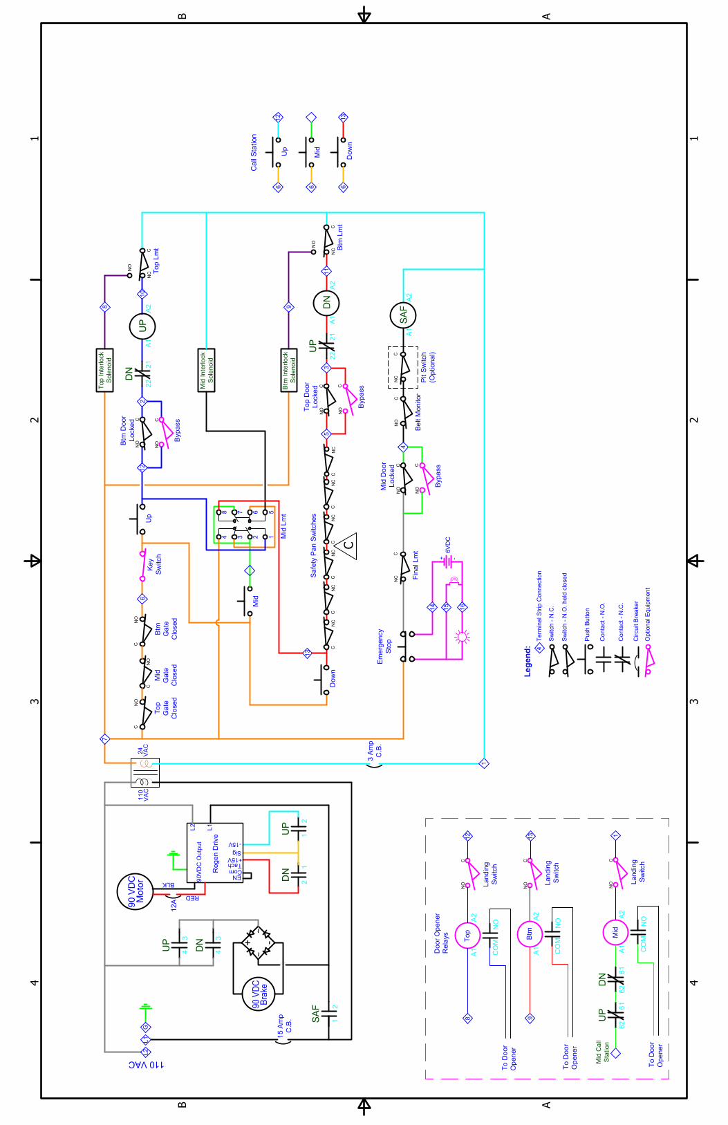
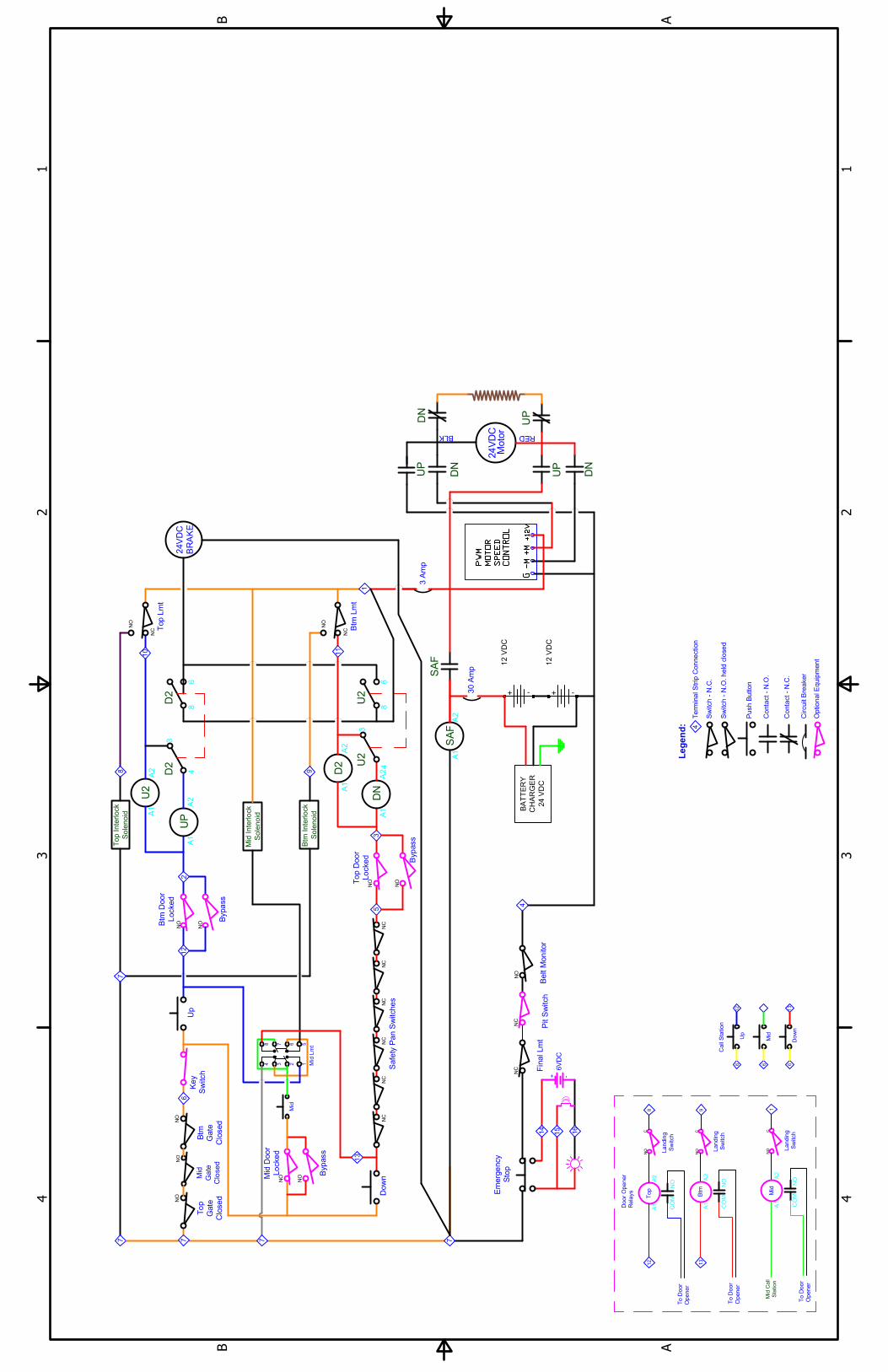
Typewritten Text
SCHEMATIC, CPL AC, 3-STOP 44331 REV C
1 1
2 2
3 3
4 4
AA
BB
VA
C
VA
C
24
110
15
A
mp
C
.B
.
3 A
mp
C
.B
.
90 V
DC
Motor
BR
AK
E
Ca
ll
Co
ntro
l
NC
NC
NO
NC
Em
erg
en
cy
Stop
Platform
Con
trol
CN
CC
NC
CN
CC
NC
Sa
fe
ty P
an
Lower
Limit
Upper
Limit
Final
Limit
Travel C
able #4
4042 / 43 / 44
NO
C
NO
SO
L
Gate
Clo
se
d
C
NO
SO
L
Gate
Clo
se
d
Optio
nal
Platform
Ga
te
Op
tiona
l
Top
La
nding
Gate
Option
al
Ligh
te
d
Ala
rm
NC NO
NC
Lower
Bypass
Upper
Bypass
NO
1
2 3
4
6
7
8 9
5
1
2
1
2 3
4
6
5
1
2 3 4
6
5
1
2 3 4
6
7
8 9
51
2
3
1
2
3 1
2 3 4
1
2
12
3 4
6
5
1
2
3
-1
5V
Sig
+1
5V
L2
L1
90VDC Output
12A
Regen Drive
Ta
ch
Co
m
EN
NO
Belt
Mon
ito
r
1 1
Electric
Strike
P
ow
er
1
1
2
31
2 3 4
6
5
NC NO
Mid
Bypass
Ca
ll
Co
ntro
l
Ca
ll
Co
ntro
l
Mid
Bo
tto
mT
op
9
7
8
Mid D
oo
r
In
terlock
4 3 2 1
8 7 6 5
Op
tio
na
l T
op O
R B
ottom
Trine
D
oor S
trike
1
2 3
4
6
5
C
NC
SO
L
Do
or
Clo
se
d
Do
or
Lo
cke
d
C
NC
Po
wer
Mo
du
le
1
AC
AC
DC
+
DC
-
AC
AC
DC
-
DC
+
Op
tio
na
l M
idd
le T
rine
Doo
r S
trike
1
2 3 4
6
5
C
NC
SO
L
Doo
r
Clo
sed
Do
or
Lo
cked
C
NC
Pow
er
Mod
ule
1
AC
AC
DC
+
DC
-
joe.brock
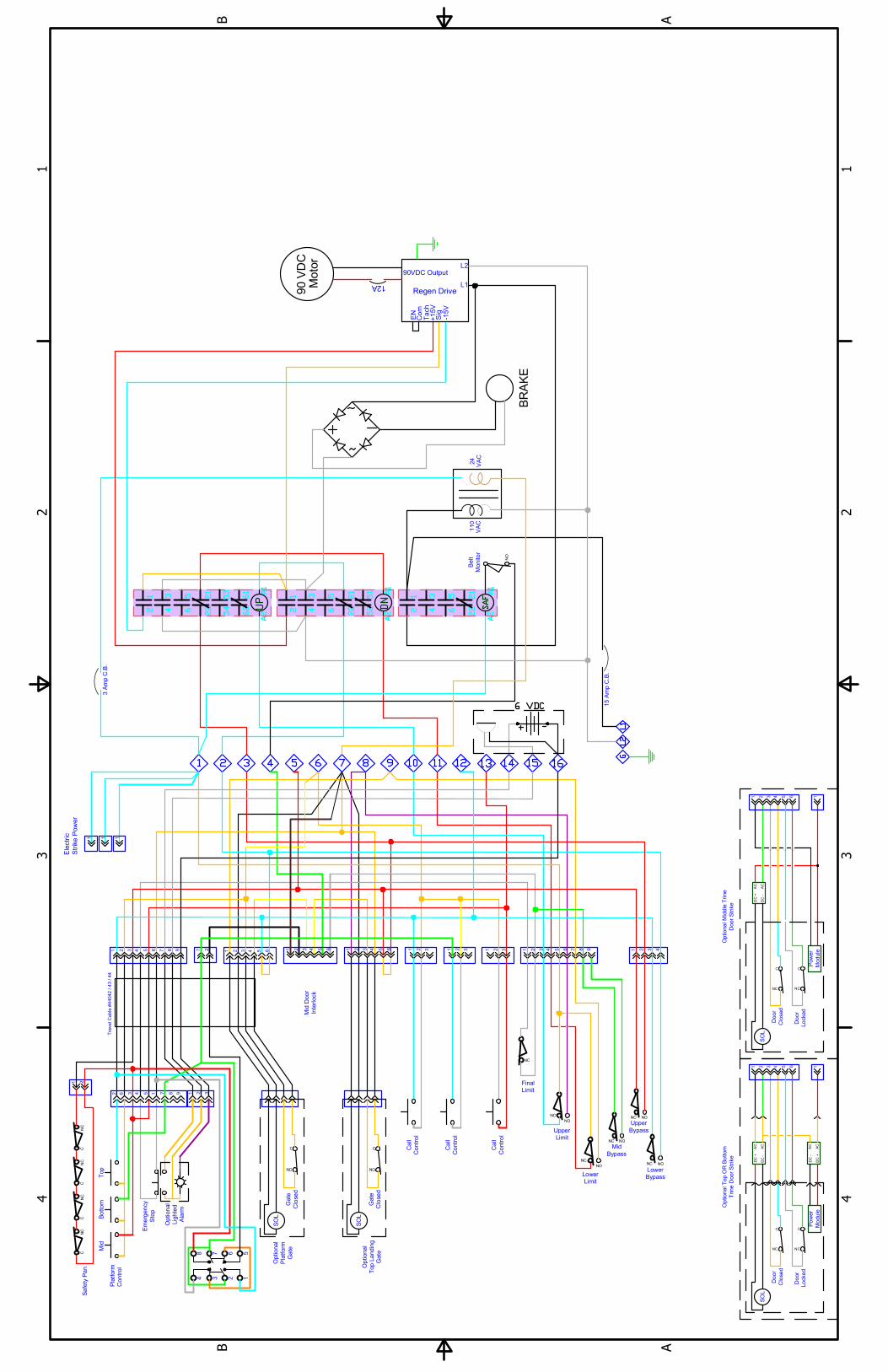
Typewritten Text
WIRING DIAGRAM, CPL AC, 3-STOP 44331 REV C
1 1
2 2
3 3
4 4
AA
BB
NC
C
C
CH
AR
GE
R
BA
TT
ER
Y
MO
TO
R
SP
EE
D
NO
C
C
CO
NT
RO
L
NO
CN
O
CN
O
-
C
NO
NC
12 V
DC
24 V
DC
NC
C
G
PW
M
NC
+
+1
2V
+M
C
NC
C
NC
C
12 V
DC
NO
NC
CC
CN
CC
NC
NC
NC
NC
-
+
NO
CC
-M
Brake
Motor
15
16
REDBLK
24V
DC
Belt M
onitor
Call S
en
d
24V
DC
Up
Top Lm
t
Dow
n
Fin
al Lm
t
Key S
witch
(O
PT
IO
NA
L)
Em
ergency
Stop
4
Key S
witch
(O
PT
IO
NA
L)
Te
rm
inal S
trip
C
on
nection
Safety P
an S
witche
s
2
3
8
4
10
11
1
Sw
itch - N
.C
.
Sw
itch - N
.O
. held closed
Push B
utton
Contact - N
.O
.
Contact - N
.C
.
7
7 7
Circuit B
re
aker
Leg
en
d:
30
A
mp
3 A
mp
Top
Gate
Closed
6
7
(O
ption
al)
Pit S
witch
Btm
Gate
Closed
Btm
Lm
t
9
Btm
D
oor
Locked
Bypass
Braking Resistor
Top D
oor
Locked
Bypass
5
+
-
6V
DC
Optio
nal E
quipm
ent
14
12
13
3
4
8
68
3
4
DN
U2
UP
DN
UP
DN
To
p Interlock
Btm
Inte
rlock
A1
A2
So
le
no
id
A1
A1
D2
A1
DN
A2
A2
U2
UP
SA
F
SA
F
So
le
no
id
U2
D2
D2
A2
A1
6
UP
joe.brock
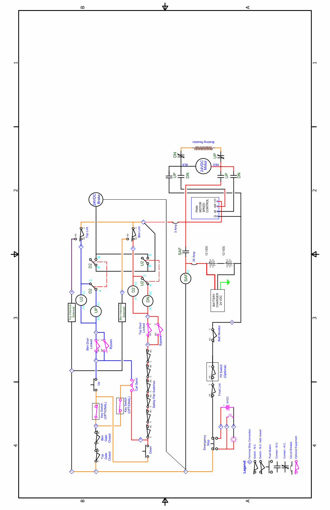
Typewritten Text
SCHEMATIC, CPL DC, 2-STOP 44141 REV F
1 1
2 2
3 3
4 4
AA
BB
24
V
DC
Motor
50W-3Ω
Optional T
op or B
ottom
Electric D
oor S
trike
BR
AK
E
NC
NO
Belt
Monitor
Ca
ll S
en
d
NC
NC
NO
NC
Em
erg
en
cy
Sto
p
Pla
tfo
rm
Co
ntro
l
CN
C
Sa
fe
ty P
an
X6
Lower
Limit
Upper
Limit
Final
Limit
Travel C
able #440
42 / 43 / 44
Pla
tform
C
ontrol
#49
218
Ca
ll S
end #
493
00
Gate
C
all
Send H
RN
S
#4
401
2
Lim
it S
witch H
RN
S #
440
07
NO
C
NO
SO
L
Ga
te
Clo
se
d
C
NO
SO
L
Ga
te
Clo
se
d
Op
tio
na
l
Pho
ne
Ja
ck
Op
tio
na
l
Pla
tfo
rm
Ga
te
Optio
na
l
To
p L
an
din
g
Ga
te
Op
tion
al
Lig
hte
d
Ala
rm
Ca
ll S
en
d
NC NO
NC
Lower
Bypass
Upper
Bypass
NO
Option
al T
op
o
r B
otto
m
Ele
ctric D
oo
r S
trike
1
2
3 4
6
7
8 9
5
1
2
1
2 3 4
6
5
1
2 3 4
6
5
1
2 3
4
6
7
8 9
5
1
2
3
1
2
3 1
2 3 4
1
2
1
2
3
4
6
5
1
2 3
1
2
SO
L
Do
or
Clo
se
d
Do
or
Lo
cke
d
1
2 3 4
6
5
joe.brock
Typewritten Text
WIRING DIAGRAM, CPL DC, 2-STOP 44141 REV F
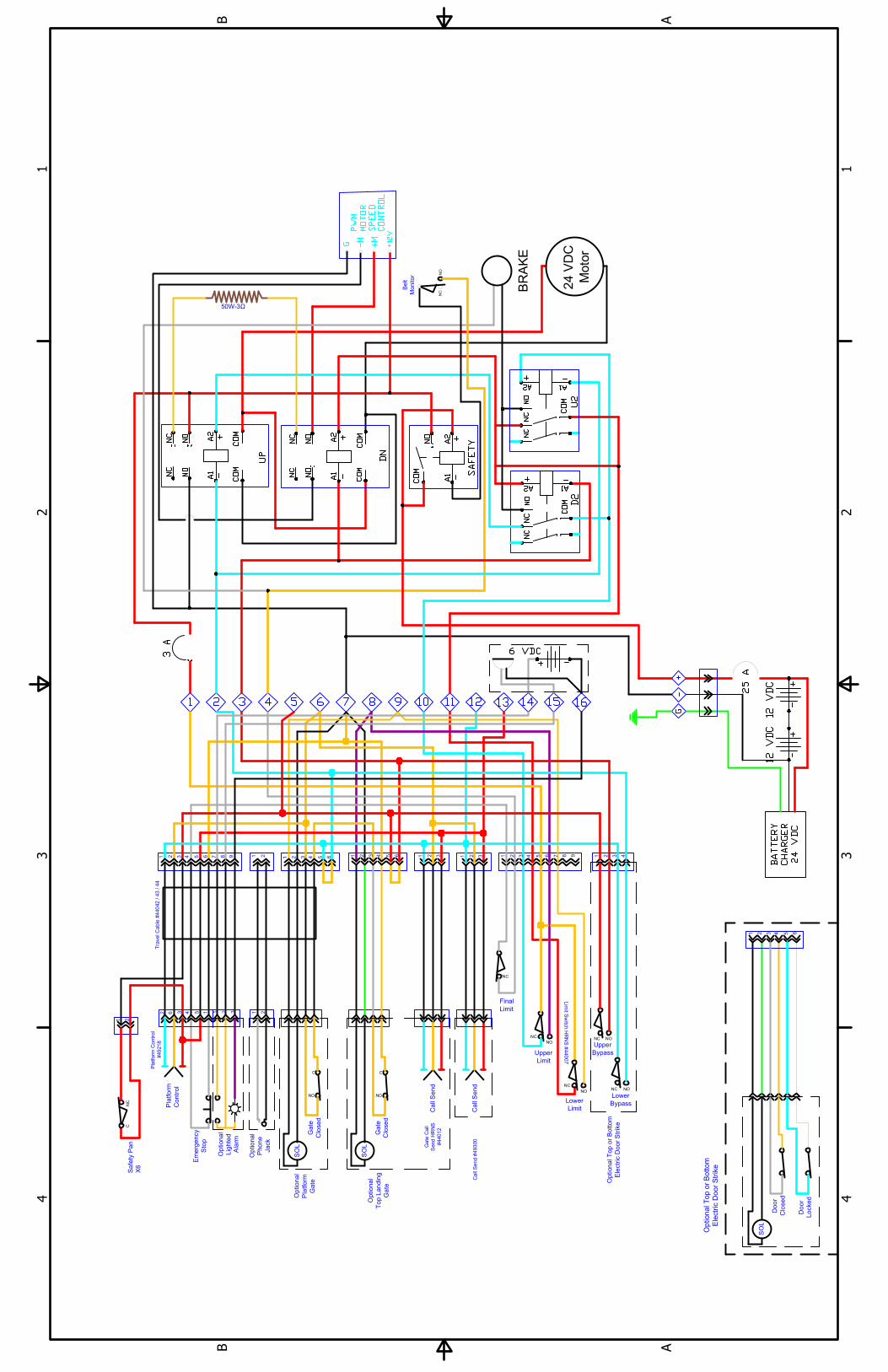
1 1
2 2
3 3
4 4
AA
BB
Up
Top
L
mt
UP
A1
A2
Dow
n
DN
A1
A2
Top Interlock
Solenoid
Final Lm
t
NC
Ke
y
Sw
itch
SA
F
Em
erge
ncy
Sto
p
4T
erm
ina
l S
trip C
on
ne
ction
Safe
ty P
an S
witche
s
NC
NC
NC
NC
2
3
8
4
10
11
1
12
13
Sw
itch
- N
.C
.
Sw
itch
- N
.O
. h
eld
clo
se
d
Pu
sh B
utton
Co
nta
ct - N
.O
.
Co
nta
ct - N
.C
.
Circuit B
re
aker
Leg
en
d:
30 A
mp
To
p
Gate
Close
d
6
7
NO
Btm
Gate
Closed
NO
NC
Btm
Lm
t
Btm
Interlock
Solenoid
9
Btm
D
oo
r
Locked
Bypa
ss
To
p D
oo
r
Lo
cke
d
Byp
ass
5
+ -
6V
DC
Be
lt M
on
itor
NO
Op
tio
na
l E
quip
men
t
NC
NO
NO
14
15
16
U2
A1
A2
D2
A1
A2
SA
F
D2
D2
+ +
12
V
DC
BA
TT
ER
Y
CH
AR
GE
R
24
V
DC
--
12
V
DC
24V
DC
BR
AK
E
NO
NO
NO
NO
Mid
4 3 2 1
8 7 6 5
Mid
L
mt
Mid Interlock
Solenoid
Call S
tation
Up
Mid
Do
wn
13
12
6 6 6
Mid
Gate
Clo
sed
NO
24
VD
C
Moto
r
3 A
mp
DN
UP
DN
UP
RED
DN
UP
BLK
7
7 7 7
A1
NC
Pit S
witch
NC
NC
A2
Mid D
oo
r
Lo
cke
d
Byp
ass
NO
NO
13
12
1
NO
CO
M
A1
A2
NO
C
NO
C
NO
C
Mid
C
all
Sta
tio
n
NO
CO
M
A1
A2
NO
CO
M
A1
A2
Door O
pener
Relays
Top
Btm
Mid
Landing
Sw
itch
Landing
Sw
itch
Landing
Sw
itch
To D
oor
Opener
To D
oor
Opener
To D
oor
Opener
8 9
4
3
86
U2
U2
4
3
86
joe.brock
Typewritten Text
joe.brock
Typewritten Text
joe.brock
Typewritten Text
WIRING SCHEMATIC, CPL DC, 3-STOP 640-00005 REV A

HIGHLANDER CPL– TWO YEAR WARRANTY CERTIFICATE
LIMITED WARRANTY CERTIFICATEProducts Covered: CPL400 – 1400; EPL400 – 1400; TG400; CPL400P
Harmar warrants to the original purchaser of a Highlander Commercial Vertical Platform Lift (CPL) manufactured by us to be free from defects in material, mechanical and electrical components (parts) for a period of two (2) years, provided that the products have been installed, maintained and operated properly by an Authorized Harmar Distributor or certified Harmar Installer.
EXCEPTIONS TO THIS LIMITED WARRANTY ARE: PLEASE READ CAREFULLY
• Harmar CPL’s and EPL’s installed outdoors must include thePremium Protection Package to maintain 2-year warranty;otherwise warranty is limited to one (1) year.
• Batteries are limited to one (1) year with a Harmar supplied/approved charger.
• Damage resulting from improper installation or operation• Additional parts/labor related to code compliance that were not
identified on the original order• Negligence, alterations, abuse or misuse of the equipment• Fire, flood, acts of God• Shipping damage
This warranty starts on the date of initial product installation (not to exceed 90 days from the date of manufacture), provided the warranty certificate is completely filled out and returned to Harmar within ten (10) days of installation. Harmar and its dealers shall not be liable for any consequential, special or incidental damages arising out of the purchase or use of the unit or resulting from the breach of this Limited Warranty, or any implied warranty. The limit of liability of Harmar and its dealer hereunder shall be the unit’s purchase price. Some states do not allow limitations on how long an implied warranty lasts or the exclusion or limitation of incidental or consequential damages, or legal remedies, so these above limitations may not apply to you. All warranty claims must be reported to the dealer from whom the lift was purchased as they have responsibility for handling your warranty claim. The dealer is to contact the Technical Services Department of Harmar and provide the serial number of the product along with a description and evidence of the defect(s) supporting a warranty claim. Dealers may charge for labor, service, travel, or other associated costs to make repairs, and such charges are not covered by this Limited Warranty. It is permissible to have any repairs or replacement work done as a result of any defects in material and workman-ship by someone other than the Dealer under this Limited Warranty. However, the Limited Warranty does not cover any charges or expenses assessed by any such other person or company performing such repairs or replacement work. All parts used to replace defective materials must be genuine Harmar parts to be covered by this Limited Warranty. This Limited Warranty gives you specific legal rights, and you may have other rights which vary from state to state. Harmar will not be charged for labor, consequential damage or repair expenses. Harmar will not, under any circumstances, be liable for the loss of the use of its products or loss of time. Defective parts must be returned, if requested, prepaid, to Harmar for inspection prior to credit or replace-ment. At Harmar’s discretion, any part found to have been modified, over-stressed, damaged by accident, or misused is not covered by this warranty. THIS WARRANTY IS IN LIEU OF ALL OTHER WARRANTIES OR CONDITIONS, INCLUDING ALL IMPLIED WARRANTIES OR MERCHANTABILITY OR FITNESS FOR A PARTICULAR PURPOSE, AND THERE ARE NO WARRANTIES THAT EXTEND BEYOND THE DESCRIPTION OF THE LIMITED WARRANTY DESCRIBED HEREIN.
• Parts used that are not approved by Harmar Mobility, LLC.• Labor fees for installation work, repair or service calls are not covered• Outdoor installation within 1 mile of a coastline reduces warranty
to 180 days and expressly excludes rust after 30 days. Warranty isextended to 2 years with Premium Protection Package Option.
• Due to the nature of steel construction being permanently placed inan outdoor environment and its inherent unpredictability, minor paint defects and cosmetic rust are not covered after 30 days by Harmar’sLimited Warranty.
• Harmar enclosures, when used, are designed to protect a CPL and itsusers from being directly affected by the elements.It is NOT intended nor designed to be completely water proof.
Warranty2
Effective August 1, 2017

NOTES

P/N: 630-00042 Rev C
Highlander Commercial Platform LiftInstallation and Owner's Manual
Related Documents