Abstract—The demands of taller structures are becoming imperative almost everywhere in the world in addition to the challenges of material and labor cost, project time line etc. This paper conducted a study keeping in view the challenging nature of high-rise construction with no generic rules for deflection minimizations and frequency control. The effects of cyclonic wind and provision of outriggers on 28- storey, 42-storey and 57-storey are examined in this paper and certain conclusions are made which would pave way for researchers to conduct further study in this particular area of civil engineering. The results show that plan dimensions have vital impacts on structural heights. Increase of height while keeping the plan dimensions same, leads to the reduction in the lateral rigidity. To achieve required stiffness increase of bracings sizes as well as introduction of additional lateral resisting system such as belt truss and outriggers is required. Keywords—Cyclonic wind regions, dynamic wind loads, Along- wind effects, Crosswind response, Fundamental frequency of vibration. I. INTRODUCTION HIS paper discusses the deflection control and frequency optimization by using belt truss and outrigger system for various height of building structure. Similar study is conducted before by Fawzia et al [1], where; authors have compared deflection variation by using up to three belt truss and outrigger system for same height. However; current paper will outline the comparison of belt truss and outriggers using 28-storey, 42-storey and 57-storey high building models i.e. 98 m, 147 m, and 199.5 m respectively. The lateral loads used are Wind Cyclonic conditions as outlined in Australian Standard [2]. These prototypes are constructed in Strand7 [3] and an initial model is run for natural frequency of vibration. The frequency values of basic models (i.e. model without outrigger systems) are used to calculate along-wind and crosswind actions on building. The deflection variations under these loads are analyzed by providing various combinations of bracings systems (i.e. core walls, outriggers and belt truss). S. Fawzia is with Department of Urban Development, Faculty of Built Environment and Engineering, Queensland University of Technology, Brisbane 4000, Australia. (Phone: 617-31381012; Fax: 617-3138 1170; e- mail: [email protected]). A. Nasir is Principal of Safe Australia Consulting Engineers and visiting academic with Department of Urban Development, Faculty of Built Environment and Engineering, Queensland University of Technology, Brisbane 4000, Australia. (e-mail: [email protected]). T. Fatima is student in Department of Urban Development, Faculty of Built Environment and Engineering, Queensland University of Technology, Brisbane 4000, Australia. (e-mail: [email protected]). II. BACKGROUND In last few decades, city growth has become a significant trait of urban development worldwide. These demographic changes have influenced the life style of common people that include livelihood standard, approach to amenities, eating habits, economic levels and living spaces etc. The present trend of people moving toward metropolis has caused scarcity of living space within cities and thus; demanding them to grow upwards i.e. triggering the construction of taller and taller structures. Mendis et al [4], proposed that this demand is always auxiliary to a multitude of variables, such as strength, durability, forming techniques, material characteristics, nature and extent of reinforcement, aesthetics and much more. Thus; design intent has always been to accomplish an understandable necessity through communities to erect or re- erect structures deemed to be affordable and safe during their life span. The structure or building must be converted into or remain a natural part of the developed milieu. Gabor [5], states that the main aim of structural design is to provide a safe load path during any stage of construction, building lifespan and while its demolition, under all possible loads and effects and within acceptable risk limits set up by society. Nevertheless; a progressively aggressive construction industry stipulates cost effectiveness besides architecturally challenging structures that compel engineers to devise newer techniques to innovate and apply mix and match approach to the available material and resources. As mentioned by Ali [7], that an innovative system of casting square, twisted, steel bars with concrete as a frame with slabs and concrete exterior walls was used in the Ingalls Building in Cincinnati, Ohio, the first 15-story concrete "skyscraper" built in 1903 by Elzner. The introduction of composite construction to tall tubular buildings, first conceived and used by Fazlur Khan of Skidmore, Owings & Merrill (SOM) in the 1960s, has paved the way for super-tall composite buildings like the Petronas Towers and the Jin Mao building in the present era. Consequently; tall building construction is promptly transforming and its frontiers are continually being assessed and extended. The super tall buildings such as the Burj Khalifa, under construction 151 storey Incheon Tower in South Korea and proposed 1 km tower in Saudi Arab are all instigated by such innovations [4]. The fundamental design criterions for high-rise building are strength, serviceability and stability whereas Jayachandran [7] also includes human comfort into these. According to the guidelines of Australian Standards [8], [2], [9] and [10], Stability and Strength are covered by Ultimate limit state design while Serviceability limit state applies to the short and long term deflections (that includes creep and shrinkage) of whole structure as well as its components. S. Fawzia, A. Nasir and T. Fatima Study of the Effectiveness of Outrigger System for High-Rise Composite Buildings for Cyclonic Region T World Academy of Science, Engineering and Technology 60 2011 937

Welcome message from author
This document is posted to help you gain knowledge. Please leave a comment to let me know what you think about it! Share it to your friends and learn new things together.
Transcript
Abstract—The demands of taller structures are becoming
imperative almost everywhere in the world in addition to the
challenges of material and labor cost, project time line etc. This paper
conducted a study keeping in view the challenging nature of high-rise
construction with no generic rules for deflection minimizations and
frequency control.
The effects of cyclonic wind and provision of outriggers on 28-
storey, 42-storey and 57-storey are examined in this paper and certain
conclusions are made which would pave way for researchers to
conduct further study in this particular area of civil engineering.
The results show that plan dimensions have vital impacts on
structural heights. Increase of height while keeping the plan
dimensions same, leads to the reduction in the lateral rigidity. To
achieve required stiffness increase of bracings sizes as well as
introduction of additional lateral resisting system such as belt truss
and outriggers is required.
Keywords—Cyclonic wind regions, dynamic wind loads, Along-
wind effects, Crosswind response, Fundamental frequency of
vibration.
I. INTRODUCTION
HIS paper discusses the deflection control and frequency
optimization by using belt truss and outrigger system for
various height of building structure. Similar study is
conducted before by Fawzia et al [1], where; authors have
compared deflection variation by using up to three belt truss
and outrigger system for same height. However; current paper
will outline the comparison of belt truss and outriggers using
28-storey, 42-storey and 57-storey high building models i.e.
98 m, 147 m, and 199.5 m respectively. The lateral loads used
are Wind Cyclonic conditions as outlined in Australian
Standard [2]. These prototypes are constructed in Strand7 [3]
and an initial model is run for natural frequency of vibration.
The frequency values of basic models (i.e. model without
outrigger systems) are used to calculate along-wind and
crosswind actions on building. The deflection variations under
these loads are analyzed by providing various combinations of
bracings systems (i.e. core walls, outriggers and belt truss).
S. Fawzia is with Department of Urban Development, Faculty of Built
Environment and Engineering, Queensland University of Technology, Brisbane 4000, Australia. (Phone: 617-31381012; Fax: 617-3138 1170; e-
mail: [email protected]).
A. Nasir is Principal of Safe Australia Consulting Engineers and visiting academic with Department of Urban Development, Faculty of Built
Environment and Engineering, Queensland University of Technology,
Brisbane 4000, Australia. (e-mail: [email protected]). T. Fatima is student in Department of Urban Development, Faculty of
Built Environment and Engineering, Queensland University of Technology,
Brisbane 4000, Australia. (e-mail: [email protected]).
II. BACKGROUND
In last few decades, city growth has become a significant
trait of urban development worldwide. These demographic
changes have influenced the life style of common people that
include livelihood standard, approach to amenities, eating
habits, economic levels and living spaces etc. The present
trend of people moving toward metropolis has caused scarcity
of living space within cities and thus; demanding them to
grow upwards i.e. triggering the construction of taller and
taller structures.
Mendis et al [4], proposed that this demand is always
auxiliary to a multitude of variables, such as strength,
durability, forming techniques, material characteristics, nature
and extent of reinforcement, aesthetics and much more. Thus;
design intent has always been to accomplish an
understandable necessity through communities to erect or re-
erect structures deemed to be affordable and safe during their
life span. The structure or building must be converted into or
remain a natural part of the developed milieu.
Gabor [5], states that the main aim of structural design is to
provide a safe load path during any stage of construction,
building lifespan and while its demolition, under all possible
loads and effects and within acceptable risk limits set up by
society.
Nevertheless; a progressively aggressive construction
industry stipulates cost effectiveness besides architecturally
challenging structures that compel engineers to devise newer
techniques to innovate and apply mix and match approach to
the available material and resources. As mentioned by Ali [7],
that an innovative system of casting square, twisted, steel bars
with concrete as a frame with slabs and concrete exterior walls
was used in the Ingalls Building in Cincinnati, Ohio, the first
15-story concrete "skyscraper" built in 1903 by Elzner. The
introduction of composite construction to tall tubular
buildings, first conceived and used by Fazlur Khan of
Skidmore, Owings & Merrill (SOM) in the 1960s, has paved
the way for super-tall composite buildings like the Petronas
Towers and the Jin Mao building in the present era.
Consequently; tall building construction is promptly
transforming and its frontiers are continually being assessed
and extended. The super tall buildings such as the Burj
Khalifa, under construction 151 storey Incheon Tower in
South Korea and proposed 1 km tower in Saudi Arab are all
instigated by such innovations [4].
The fundamental design criterions for high-rise building are
strength, serviceability and stability whereas Jayachandran [7]
also includes human comfort into these. According to the
guidelines of Australian Standards [8], [2], [9] and [10],
Stability and Strength are covered by Ultimate limit state
design while Serviceability limit state applies to the short and
long term deflections (that includes creep and shrinkage) of
whole structure as well as its components.
S. Fawzia, A. Nasir and T. Fatima
Study of the Effectiveness of Outrigger System
for High-Rise Composite Buildings for
Cyclonic Region
T
World Academy of Science, Engineering and Technology 60 2011
937

Outrigger systems are generally very effective in fulfilling
the serviceability requirements of tall buildings. Rahgozar et al
[11], states that in this system, columns are tied to the belt
trusses. Therefore, in addition to the traditional function of
supporting gravity loads, the columns restrain the lateral
movement of the building. When the building is subjected to
lateral forces, tie-down action of the belt truss restrains
bending of the shear core by introducing a point of inflection
in its deflection curve. This reversal in curvature reduces the
lateral movement at the top. The belt trusses function as
horizontal fascia stiffeners and engage the exterior columns,
which are not directly connected to the outrigger belt truss.
Outriggers have been in constant used in various high-rise
developments as mentioned above, however; their use and
provision is specific to a particular construction or building
structure. Usually structural engineers have to conduct a
rigorous analysis with trial and error approach before a
conceptual set of information can be achieved, that enable
them to estimate certain primary information required by
developers or clients, before beginning of a project. Hence;
certain generic rules and principals are needed that can help
structural designer to compute requirement of bracings (i.e.
core walls, outriggers, belt truss etc.) based on structure height
and plan dimensions (i.e. width and length). These interns
would be helpful in the approximate judgment of various
quantities and cost (i.e. material, labor coast, project time line
etc.) without indulging in rigorous analysis and wind tunnel
testing at initial stage of project design work.
This investigation tries to move the academic research
towards fulfilling the gap in this essential and critical aspect of
civil engineering.
III. LOADINGS
The actions or loads acting on tall buildings can be broadly
classified into two types;
Gravity Loads
Lateral loads
A. Gravity loads
The loads acting downwards because of the effect of
acceleration due to gravity are termed as gravity loads. These
intern generally classified in three types as:
Inherit self weight of structural elements depending on
member size and material properties.
Superimposed dead loads.
Live loads.
1. Self weight of structure
Structural self weight is adopted for the prototype as follow;
i) Composite Slab
Slab overall depth is 120mm including 1.0 BMT Lysaght
Bondek [12] metal sheeting. Equivalent Elastic modulus and
density is entered in the Strand7 [3] model. The overall depth
is selected as per the loads assumptions given in onesteel table
[13] for primary and secondary beams sizes.
ii) Secondary beams and Primary beams
Structural steel secondary beams and primary beam are
provided with approximate sizes as given in the Onesteel
tables [13]. These sizes are adopted readily based on
assumptions of superimposed loads and live loads provided in
the table for typical office floor and given span lengths.
iii) Composite column
The weight of a column is a characteristic of its cross-
sectional area and material density. The cross-sectional area
depends on the loads carried by column as per its tributary
area on each level/floor.
The size of column provided other variables remain
constant, is directly proportional to the load it carries, hence;
Cross-sectional area reduces as building height increases.
iv) Reinforced concrete (RCC) wall
Reinforced concrete wall self weight is also a characteristic
of its cross-sectional area, however; the gravity loads they
carry are usually far below their capacities. The walls are
mainly treated as lateral load resisting elements and effective
in controlling the lateral deflections and fundamental
frequency of structure. The thicknesses satisfy the minimum
requirement of Building code of Australia [14], for fire and
durability as well as to provide enough rigidity in order to
keep the fundamental frequency of vibration under certain
limits so that the Australian Standard prescribe limits [2]
could be applicable.
2. Super Imposed Dead loads (SDL)
Superimposed dead loads consist of loads of permanent
fixtures and fittings such as ceilings, air-conditioning ducts,
floor finishes, partitions etc.
In this model approximate value of superimposed dead
loads i.e. 1.5 kN/m2 as describe in Onesteel tables [13] for a
typical office building is adopted.
3. Live loads (LL)
Live loads mainly correspond to human loads and they are
highly variable. Australian standard [15], recommend live load
reduction based on tributary areas to account for their
wavering effects.
Typical office LL is adopted for this paper is 3 kN/m2.
B. Cyclonic wind load
The structure is tested under worst wind loads for Cyclonic
region D as per Australian wind standard [2], whereas;
guidelines of Australian standard for general principals [8] are
followed for the return period for serviceability limit state.
The model is tested for X and Y wind direction initially to
establish the direction of worst loads effects. In this instance it
came out to be the Y-direction. The models are then checked
in Y- direction wind loads for Along-wind, Crosswind and
combine load effects.
The main parameters are;
Basic Wind Speed = 53 m/s
Cyclonic Wind Region = D
Average recurrence interval (R) = 25 yrs
Terrain Category = Category 1
The site wind speed is given by;
Vsit,β = VR Md (Mz,cat x Ms x Mt) m/s
Where
β = cardinal direction clockwise from true north.
Md = wind direction multiplier
Ms = shielding multiplier
World Academy of Science, Engineering and Technology 60 2011
938
Mt = topographic multiplier
Mz,cat = terrain/height multiplier. (It varies with structural
height however; for calculating the dynamic load factor “z” is
taken equal to “h”).
Design wind pressure is given as:
p = (0.5 ρair) [Vdes,θ]2 Cfig Cdyn (kPa)
Where:
ρair = density of air
Vdes,θ = building orthogonal design speed
Cfig = aerodynamic shape factor. It is calculated assuming an
effectively sealed environment within the building.
Cdyn = The dynamic response factor .
i) Along-Wind response
Dynamic response factor (Cdyn ) represents Along-wind
response in wind sensitive structures such as high rise
buildings, where fundamental frequency of vibration falls
between the range of 0.2 Hz to 1.0 Hz. It is calculated as:
ζ = ratio of structural damping to critical damping of a
structure.
Ih = Turbulence intensity obtained by setting "z = h" & Terrain
category 1.
gv = peak factor for the upwind velocity fluctuations.
Bs = Background factor given as follow:
h = average roof height of structure above ground (m).
s = height of the level where action effects are calculated (m).
bsh = average breath of structure between height h and s (m).
Lh = a measure of the integral turbulence length scale at height
h given as: 85 (h/10)0.25
(m).
Hs = height factor for the resonant response which equals to:
1 + (s/h)2
gR = peak factor for resonant response (10 min period), given
by :
na = first mode natural frequency of vibration in along wind
direction obtained from computer analysis (Hz).
S = size reduction factor given as:
b0h = average breath of structure between height 0 and h (m).
Vdes,θ = design wind speed determined at building height h.
Et = (p/4) times spectrum of turbulence in the approaching
wind stream, given as:
N = reduced frequency (non dimensional) given as:
naLh [ 1 + (gv Ih)] / Vdes,θ
ii) Crosswind Response
The equivalent static crosswind force per unit height is
given by:
weq (z) = 0.5ρair [Vdes,θ]2 d (Cfig Cdyn) N/m
Where;
d = horizontal depth of structure parallel to wind stream
(Cfig Cdyn) = the product of effective aerodynamic shape
factor and dynamic response factor is given as;
k = mode shape power exponent for the fundamental mode.
Iz = turbulence intensity at 2h/3 of building height (use
interpolation if required).
z = reference height on structure above average ground level
(m).
Km = mode shape correction factor for crosswind acceleration,
given by; Km = 0.76 + 0.24k
Vn = reduced velocity (m/s), calculated as:
nc = first mode natural frequency of vibration in the cross
wind direction obtained from computer analysis (Hz).
b = breath of structure normal to wind direction (m).
Cfs = crosswind force spectrum coefficient.
As the wind actions are trapezoidal in nature i.e. varies with
height, these are generated by using Excel sheet for each
building type .These are then applied in Strand7 [3], as
uniformly distributed horizontal force in kN/m to each storey.
IV. FRAMING LAYOUT
The model layout selection is primarily dictated by
Australian Standards limitations and applications. The current
Australian standard [2] is only applicable for building heights
up to 200 m and frequency range from 0.2 Hz to 1.0 Hz.
Therefore the maximum model height is chosen within these
limitations.
The model layout selected in this instance is L-shaped with
walls on the right and left hands as well as top left corner of
building (Fig. 1). The height of each storey level is 3.5 m
which a typical office level used in the country and it can
accommodate the service ducts etc.
World Academy of Science, Engineering and Technology 60 2011
939

Fig. 1 Plan of typical floor level
Fig. 2 Three Dimensional Elevation
The model main features are
i) Core wall layout
The office building falls in building classification “Class 5”
of Building code of Australia [14] therefore; stairs well and
lifts are provided to satisfy the minimum access and egress
requirement.
Fig 3 shows wall layout in three models i.e. Corner wall
(CW), main right wall (RW), main left wall (LW). However:
right side wall (RSW) and left side wall (LSW) are only
provided in 57-storey model.
Fig. 3 Wall Designation
ii) Beams Layout
Secondary beams are running along the shorter dimension
and primary beams are along the longer dimensions.
iii) Column positions
Columns are at 10 m centre to centre spacing. This spacing
is chosen as desirable open space criteria for office buildings.
iv) Construction type
Simple construction is adopted according to the definition
of Australian Standard [9] and frame moment releases are
provided for primary and secondary beams (Fig. 4). Braced
core frame is provided for the lateral load resistance. The
outriggers, however; are provided when structure reaches at
height where deflections and frequencies are out of the
prescribe Australian code limits [2],[8].
Fig. 4 Partial Plan for Moment Release in Beams
v) Support at base
Column and core both are fixed at the base (Fig. 5).
Columns attract very less lateral load due to their small
rigidities comparing with the massive core wall structure [16].
The pinned and fixed base usually does not change the lateral
load attracted to the column. However; in case of pinned base,
column must be sufficiently strong to resist all the lateral
moments by themselves without transferring them to the base.
This kind of setup is usually not common in real world where
most bases especially for tall structures are either designed as
raft/mat or deep foundations.
Moment releases
30 m
X-axis
Y-axis
80 m
60 m
30 m
Height (m)
Columns
Primary Beams Secondary beams
CW
RW
LW
LSW & RSW (57-storey only)
World Academy of Science, Engineering and Technology 60 2011
940

Fig. 5 Fixed supports at base
V. ELEMENT PROPERTIES
Horizontal elements (i.e. Slab and beams) sizes are fixed as
these are only meant for carrying the local floor loads,
however the sizes of vertical elements varies with height.
Columns sizes are dominated by the gravitational loads
whereas; core wall thickness is mainly dictated by the lateral
loads.
A. Composite Columns sizes
In this model the Columns are grouped for each 5-storey i.e.
same size is provided for each 5 levels. This is based on load
variation each five levels.
The cross-sectional size is calculated by applying the
guidelines of Australian code for Concrete Structures [3].
Typical Floor loads for composite column = Slab self
weight + (Secondary Beams + Primary Beams) self weight +
SDL + LL + Column Self Weight
The composite effect is provided by using Structural Steel I-
Sections (UC and WC) from AISC capacity tables [17],
within the prescribe steel percentage limits of Australian
standard [10] (see Table I, II, II). The transformed properties
of composite columns are entered into the finite element
software [3] for analysis.
TABLE I
COLUMN SIZES FOR PROGRESSIVE 28-STOREYS (98M)
Levels
group
Interior Column Exterior Column
f’c
(MPa)
Size
(Sq.mm)
ET
(MPa) γT
(kg/m3)
Size
(Sq.mm)
ET
(MPa) γT
(kg/m3)
L26-L28 65 325 41987 2600 250 42317 2610
L21-L25 65 525 41895 2596 375 41863 2595
L16-L20 80 600 44679 2618 425 44839 2624
L11-L15 80 700 43659 2584 525 45024 2630
L6-L10 100 725 47454 2627 525 47536 2630
L1-L5 100 800 47156 2617 575 47641 2633
f’c = Concrete strength, ET = Transformed elastic modulus,
γT = Transformed density
TABLE II COLUMN SIZES FOR PROGRESSIVE 42-STOREYS (147M)
Levels
grouped
Interior Column Exterior Column
f’c
(MPa)
Size
(Sq.mm)
ET
(MPa) γT
(kg/m3)
Size
(Sq.mm)
ET
(MPa) γT
(kg/m3)
L41-L42 65 350 39909 2531 300 40815 2561
L36-L40 65 500 42356 2612 350 42524 2617
L31-L35 65 625 42145 2605 450 42137 2604
L26-L30 80 675 44881 2625 500 43385 2575
L21-L25 80 775 44273 2604 575 44122 2599
L16-L20 80 850 45172 2635 625 44692 2619
L11-L15 100 850 47682 2635 625 47209 2619
L6-L10 100 925 47180 2618 650 47802 2639
L1-L5 100 975 47064 2614 700 47031 2612
f’c = Concrete strength, ET = Transformed elastic modulus,
γT = Transformed density
TABLE III
COLUMN SIZES FOR PROGRESSIVE 57-STOREYS (199.5M)
Levels
group
Interior Column Exterior Column
f’c
(MPa)
Size
(Sq.mm)
ET
(MPa) γT
(kg/m3)
Size
(Sq.mm)
ET
(MPa) γT
(kg/m3)
L56-L57 65 300 40815 2561 300 40815 2561
L51-L55 65 475 42891 2630 350 41355 2579
L46-L50 65 625 42145 2605 450 42748 2625
L41-L45 65 750 41736 2591 550 42410 2614
L36-L40 80 775 44273 2604 550 45645 2651
L31-L35 80 850 44706 2619 625 44692 2619
L26-L30 80 925 45093 2632 675 44881 2625
L21-L25 80 1000 44877 2625 725 44940 2627
L16-L20 100 1000 47392 2625 725 47454 2627
L11-L15 100 1025 47367 2624 750 47839 2640
L6-L10 100 1075 47075 2614 775 47481 2628
L1-L5 100 1125 47013 2612 800 47871 2641
f’c = Concrete strength, ET = Transformed elastic modulus,
γT = Transformed density
B. RCC wall sizes
The initial wall thickness are supplied as per BCA [14], fire
and durability requirements. These are progressively changed
during the course of structural analysis for serviceability limit
state (see Table VI).
VI. OPTIMIZATION PROCEDURE
The three dimensional modeling is carried out in Strand7
[3], which is a finite element based software. The properties
for column and walls as outlined in Table I, II and III are input
in the model for three different models heights, in addition to
the Slab and beams properties. To achieve a structural
arrangement that satisfies frequency criteria and deflection
limits of relevant standards is a repeated task and can also be
termed as “trial and error” procedure, as Jayachandran [7]
outlines that overall optimization of tall building frame is
complex and time consuming.
The steps that have been done repeatedly for the
optimizations are:
i. Input of minimum required wall thickness, column
sizes and Slab and beam properties for first run of
model.
ii. The first Run is “Natural Frequency Analysis” that
gives the fundamental frequency of vibration of
structure. This frequency is check against the
recommended frequency by Australian standard [6].
The model is run and re-run and for each solver cycle
the wall thickness are adjusted (usually increased) in
order to get the appropriate lateral rigidity, until the
required frequency value is achieved. The
introduction of outrigger system is also beneficial
during this procedure to attain needed lateral
stiffness, however; this option is used only for 57-
storey structure.
iii. The acquired frequency is then utilized in cyclonic
wind load calculations in order to get Dynamic
Along-wind and Crosswind effects on building.
World Academy of Science, Engineering and Technology 60 2011
941
Although in this paper, frequency of basic model is
used for cyclonic wind calculations.
iv. These wind loads are applied on to the structure in
software [3]. Australian Standards advocate using
Along-wind and Crosswind effects simultaneously on
the structure, therefore: load combinations (Comb 1)
is used in Strand7 [3] to get such effects.
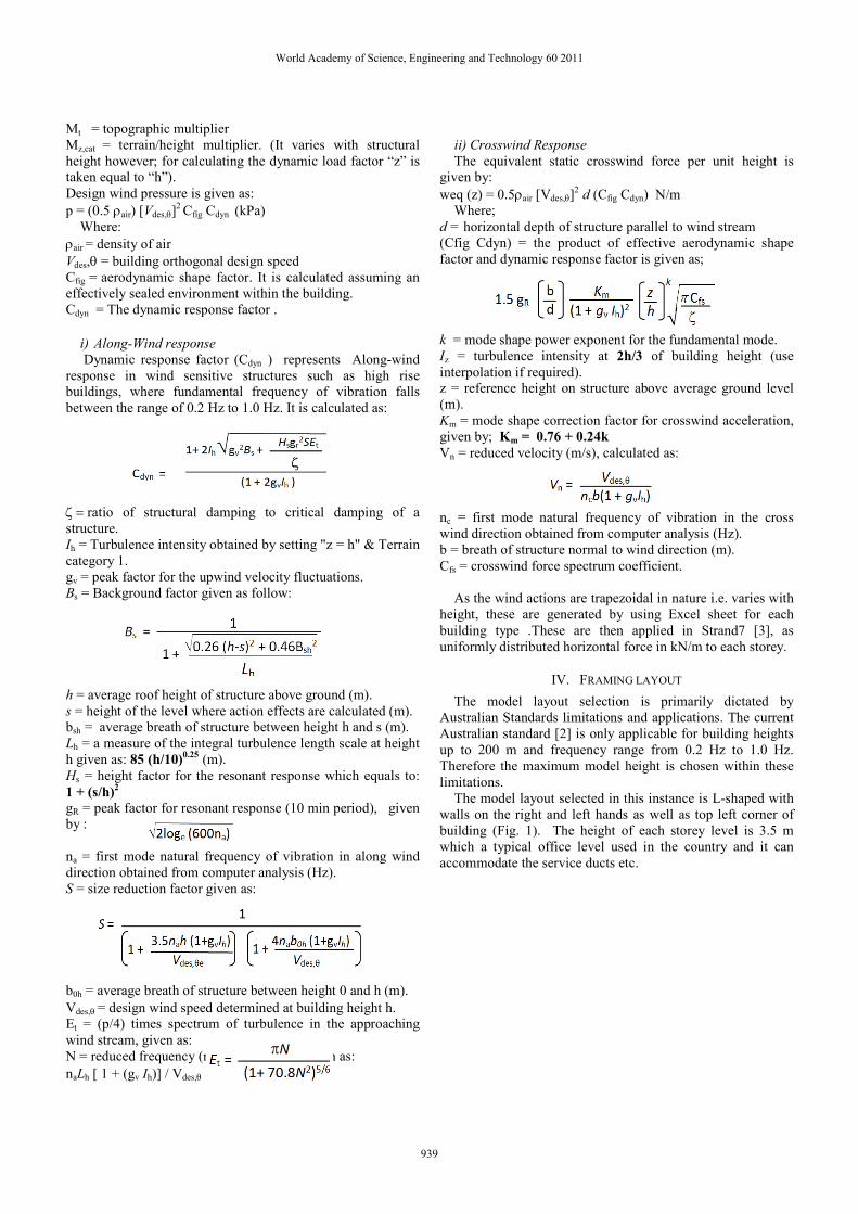
v. Serviceability (i.e. deflections) limits are checked to
measure structural capability of lateral load resistance
for Along-wind (Fig. 6), Crosswind (Fig. 7) and
combination of both as follow.
Load 1 - Along-Wind Actions
Load 2 – Crosswind Actions
Comb 1 – (Along-wind Actions + Crosswind
Actions)
Fig. 6 Along-wind actions (WY)
Fig. 7 Crosswind actions (WY)
Above steps are performed repeatedly by adjusting wall
thicknesses and introduction of outriggers at various levels
until desired results are achieved.
VII. MODELING ARRANGEMENTS
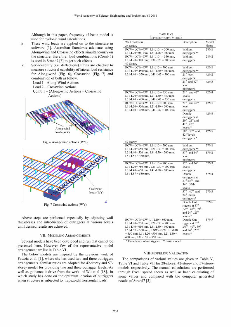
Several models have been developed and run that cannot be
presented here. However few of the representative model
arrangement are list in Table VI.
The below models are inspired by the previous work of
Fawzia et al. [1], where she has used two and three outriggers
arrangements. Similar ratios are adopted for 42-storey and 57-
storey model for providing two and three outrigger levels. As
well as guidance is drive from the work of Wu et al [18], in
which study has done on the optimum location of outriggers
when structure is subjected to trapezoidal horizontal loads.
TABLE VI
REPRESENTATIVE MODELS
Wall thickness Description Model
Name 28-Storey
RCW= LCW=CW : L1-L10 = 300 mm, L11-L20=300 mm, L31-L28 = 300 mm
Without outriggers.**
28M1
RCW= LCW=CW : L1-L10 = 350 mm,
L11-L20= 300 mm, L31-L28 = 300 mm
Without
outriggers.
28M2
42-Storey
RCW= LCW=CW : L1-L10 = 500 mm, L11-L20= 450mm , L21-L30 = 400 mm,
L31-L40 = 350 mm, L41-L42 = 300 mm
Without outriggers.**
42M1
21st level
outriggers.
42M2
21st and 42nd
level
outriggers.
42M3
RCW= LCW=CW : L1-L10 = 550 mm, L11-L20= 500mm , L21-L30 = 450 mm,
L31-L40 = 400 mm, L41-L42 = 350 mm
21st and 42nd levels
outriggers.
42M4
RCW= LCW=CW : L1-L10 = 600 mm, L11-L20= 550mm , L21-L30 = 500 mm,
L31-L40 = 450 mm, L41-L42 = 400 mm
21st and 42nd level
outriggers.
42M5
Double
outriggers at 20th , 21st and
41st , 42nd
levels.*
42M6
18th , 30th and
42nd levels
outriggers.*
42M7
57-storey
RCW= LCW=CW : L1-L10 = 700 mm,
L11-L20= 650 mm , L21-L30 = 600 mm,
L31-L40= 550 mm, L41-L50 = 500 mm, L51-L57 = 450 mm,
Without
outriggers.**
57M1
57th and 34th
level outriggers.
57M2
RCW= LCW=CW : L1-L10 = 800 mm, L11-L20= 750 mm , L21-L30 = 700 mm, L31-L40= 650 mm, L41-L50 = 600 mm,
L51-L57 = 550 mm,
57th and 34th levels outriggers.
57M3
Double
outriggers at 57th ,56th and
34th , 33th
levels.
57M4
57th , 40th and 24th levels
outriggers*
57M5
Double Out riggers at 57th
,56th , 40th , 39th
and 24th , 23rd levels.*
57M6
RCW= LCW=CW :L1-L10 = 800 mm,
L11-L20= 750 mm , L21-L30 = 700 mm,
L31-L40= 650 mm, L41-L50 = 600 mm, L51-L57 = 550 mm, LSW=RSW: L1-L10
= 550 mm, L11-L20 =500 mm, L21-L30 =
450 mm, L31- L57 = 350 mm.
Double Out
riggers at 57th
,56th , 40th , 39th and 24th , 23rd
levels.*
57M7
*Three levels of out riggers. **Basic model
VIII. MODELING VALIDATION
The comparisons of various values are given in Table V,
Table VI and Table VII for 28-storey, 42-storey and 57-storey
models respectively. The manual calculations are performed
through Excel spread sheets as well as hand calculating of
some values and compared with the computer generated
results of Strand7 [3].
Along-wind
loads (WY)
Crosswind
loads (WY)
World Academy of Science, Engineering and Technology 60 2011
942

TABLE V
MODELING VALIDATION FOR 28- STOREY
Items Manual Cals Strand7 Difference
Interior Column load (kN)
10800 10934 1.24 %
Exterior Column
load (kN) 5180 5307 2.45 %
Structure Self weight (kN)
441974 439907 4.7 %
Base shear -
Along wind response (kN)
27384 27384 0.0
Base Shear
Cross wind (kN) 23609 23616 0.0
Column load = self weight of structure/ column tributary area.
Difference = {(Manual load – strand7 output)/ Manual Load} x 100
TABLE VI
MODELING VALIDATION FOR 42- STOREY
Items Manual Cals Strand7 Difference
Interior Column
load (kN) 16988 16406 3.4 %
Exterior Column load (kN)
8140 8522 4.7 %
Structure Self
weight (kN) 763488 787936 3.2 %
Base shear -
Along wind
response (kN)
44848 46254 3.13 %
Base Shear Cross wind (kN)
36720
36700
0.0
Column load = self weight of structure/ column tributary area.
Difference = {(Manual load – strand7 output)/ Manual Load} x 100
TABLE VI
MODELING VALIDATION FOR 57- STOREY
Items Manual Cals Strand7 Difference
Interior Column load (kN)
24078 22245 7.6 %
Exterior Column
load (kN) 11547 11963 3.6 %
Structure Self weight (kN)
1307800 1258228 3.8 %
Base shear -
Along wind
response (kN)
66776
66776
0.0
Base Shear
Cross wind (kN) 51854 51960 0.2 %
Column load = self weight of structure/ column tributary area.
Difference = {(Manual load – strand7 output)/ Manual Load} x 100
IX. RESULT
The results that are achieved are presented in following
tables and graph.
A. 28-Storey model
TABLE VIII RESULTS FOR 28-STOREY
Model
Name
Frequency Deflection (mm)
1st
Mode
2nd
Mode
DY (Along-
wind)
DY (Cross
wind)
DXY
(Comb1)
28M1 0.415 .485 170 120 170
28M2 0.475 0.511 150 110 160
This model has a lowest depth to height ratio therefore; stiff
enough to lateral loads. It does not require any additional
rigidity to achieve frequency and deflection limits.
B. 42-storey model
The analysis results of various 42-storey models are given
in Table IX and a comparison of Along-wind, crosswind and
combination of both is given by Fig. 8.
TABLE IX
RESULTS FOR 42-STOREY
Model
Name
Frequency (Hz) Deflection (mm)
1st
Mode
2nd
Mode
DY
(Along-wind)
DY
(Crosswind)
DXY
(Comb1)
42M1 0.265 0.286 520 290 630
42M2 0.281 0.302 480 260 590
42M3 0.291 0.312 450 230 550
42M4 0.298 0.320 410 210 500
42M5 0.304 0.326 380 200 460
42M6 0.323 0.352 340 170 420
42M7 0.314 0.339 360 180 440
The trend of deflections is downward till 42M6 and rises in
42M7 as seen in Fig. 8. 42M6 has double outrigger one at
mid-height and other at the top of structure whereas 42M7 has
three outrigger levels approximately one third and two third
heights, in addition to one at the top. From the deflection
curve it is evident that two double levels outriggers are more
effective than three single levels outriggers.
The combination deflection is dominating whereas:
deflections in along-wind and comb 1 are greater than
Australian standard [2] limits of height/500. The crosswind
though imparts fewer effects on this building and deflection is
within the prescribe value.
Fig. 8 Deflection comparison for 42-storey
The first and second mode frequency shows similar trend as
deflection graph (see Fig. 9). Frequency values gives
somewhat predicted results, there is a marked difference
between the frequencies of two single outrigger system and
two double outriggers due to increase rigidity, the three
outriggers gives the value between the above two.
150
200
250
300
350
400
450
500
550
600
650
42M1 42M2 42M3 42M4 42M5 42M6 42M7
Deflection (mm)
Models
Along-Wind (DY)
Crosswind (DX)
Comb1 (DXY)
World Academy of Science, Engineering and Technology 60 2011
943

Frequency values (see Table IX) are however; within limits
in the first model, therefore; wind effects are the critical in this
instance hence serviceability limits need to achieve.
Fig. 9 Frequency comparison for 42-storey
C. 57-storey
This is the tallest prototype and is leaner/cylinder due to
increased height to plan ration as compared to other two
models. Therefore the lateral rigidly has reduced which will
appear by comparing deflection values in Table X to 28-storey
and 42-storey models in Table VIII and Table IX.
TABLE X
MODELING VALIDATION FOR 57-STOREY
Model
Name
Frequency (Hz) Deflection (mm)
1st
Mode
2nd
Mode
DY (Along-
wind)
DY (Cross
wind)
DXY
(Comb1)
57M1 0.166 0.180 1210 730 1450
57M2 0.184 0.197 1020 600 1260
57M3 0.188 0.201 910 550 1120
57M4 0.202 0.216 810 470 1010
57M5 0.196 0.208 860 510 1070
57M6 0.212 0.228 750 430 940
57M7 0.219 0.232 660 390 820
Reduced frequency and higher deflections corresponds to
reduced rigidity. Fig. 10 shows; that in comb 1 (i.e. combine
action of along wind and crosswind) have the maximum
deflections. the graph in Fig. 10 follows a steady downward
trend till 57M5, where a notable increase of deflection value
occurred, which shows that providing double outriggers at two
locations provide more stiffness as altogether they are four
outrigger levels instead of providing three levels of truss at
various levels (see Table IV).
The 57M7 models is supplied with three levels of double
storey outriggers with side walls, still deflections values (see
Table X) are far less than the Australian standard [2]
confinement of height/500. This means than the structure
requires further stiffness in terms of more shear walls and
bracings for limiting values of lateral deflections.
Fig. 10 Deflection comparison for 57-storey
The frequency trend is similar to the deflection as seen in
Fig. 11.Minimum requirement of 0.2 Hz can be achieved in
57M4, which has two levels of double outriggers of and again
dropped down in 57M5 with three levels of outriggers. Using
six outrigger levels i.e. 57M6 however show a very sharp
increase in frequency.
Fig. 11 Frequency comparison for 57-storey
X. CONCLUSION
The above investigation comes to the conclusion that
rigidity/stiffness of composite high-rise building is inversely
proportional to its height i.e. the lateral stiffness decreases
with increase in height of structure while keeping the other
0.2
0.22
0.24
0.26
0.28
0.3
0.32
0.34
0.36
0.38
0.4
42M1 42M2 42M3 42M4 42M5 42M6 42M7
Frequency (Hz)
Models
1st Mode
2nd Mode350
450
550
650
750
850
950
1050
1150
1250
1350
1450
57M1 57M2 57M3 57M4 57M5 57M6 57M7Deflection (mm)
Models
Along-Wind (DY)
Crosswind (DX)
Comb1 (DXY)
0.15
0.16
0.17
0.18
0.19
0.2
0.21
0.22
0.23
57M1 57M2 57M3 57M4 57M5 57M6 57M7
Frequency (Hz)
Models
1st Mode
2nd Mode
World Academy of Science, Engineering and Technology 60 2011
944

variable constant. Therefore introduction of additional bracing
system is required to keep up with the serviceability limits.
28-storey model has b: h and d:h equal to 1: 1.633 and 1:
1.225 respectively. There is not a marked difference of vertical
and plan dimensions and in this case frequency and deflections
limits could be readily attainable (see Table IX).
42-storey model has b:h and d:h equal to 1: 2.45 and 1: 1.84
respectively. Here the vertical height has exceeded more than
double in one plan dimension. Frequency limits could be
accomplished without belt truss and outrigger system but to
attain deflection limits truss system is required. This system
provides a reverse curvature and consequently reduces the
deflection at the top of structure.
57-storey model has b:h and d:h equal to 1: 3.325 and 1: 2.5
respectively. This model has vertical dimensions almost three
times of its plan dimension and as a result; it requires truss
system as well as additional stiffness in terms of shear walls to
accomplish the criteria of frequency and deflection.
Introduction of outriggers and belt truss proved to be more
efficient in deflection minimization then achieving the
required value of fundamental frequency of vibration. Since
composite buildings usually have structural steel bracings
truss and these do not have appreciable locally stiffness rather
can be very useful in providing a tie down effects between
shear walls and columns.
REFERENCES
[1] S. Fawzia and T. Fatima, Deflection Control in composite building by using Belt truss and Outrigger System. Proceedings of the 2010 World
Academy of Science, Engineering and Technology conference, pp. 25-
27 August 2010, Singapore. [2] Standard Australia/Standard New Zealand, Structural Design Action
Part 2: Wind Actions, AS/NZS 1170.2:2011.
[3] Strand7 Pty Ltd. Strand7, Finite Element Analysis System. User’s Manual 2005, Sydney, Australia.
[4] P. Mendis and T. Ngo, Design of Tall Buildings – Recent Changes.
Australasian Structural Engineering Conference (ASEC), pp. 26-27 June 2008, Melbourne Australia.
[5] P. Gabor, Concrete Buildings: past, present and future. Australian
Journal of Civil Engineering, vol. 6 No. 3, Institute of Engineers Australia 2006.
[6] M.M. Ali, Evolution of Concrete Skyscrapers: from Ingalls to Jin mao.
Electronic Journal of Structural Engineering, vol. 1, No.1, pp. 2-14 (2001).
[7] P. Jayachandran, Design of tall Buildings - Preliminary Design and
Optimization. National Workshop on High-rise and Tall buildings, University of Hyderabad, India, May 2009.
[8] Standard Australia/Standard New Zealand, Structural Design Action Part 0: General Principal, AS/NZS 1170.0:2002.
[9] Standards Australia, Steel Structure. AS 4100:1998.
[10] Australian Standards, Concrete Structures. AS 3600-2009.
[11] R. Rahgozar and Y. Sharifi, An approximate analysis of Framed tube, Shear core and Belt truss in high-rise building. Struct. Design Tall Spec.
Build. Vol. 18, pp. 607–624 (2009).
[12] BlueScope Lysaght Manual, Using Bondek- design and construction guide 2003 edition, BlueScope Steel limited, Australia.
[13] A. Ng and G. Yum, Span Tables for Simply supported Composite
Beams. Onesteel Market Mills Design Note DN3. Ed1.1, Nov 2005. [14] Building Code of Australia (BCA). Volume 1 and Edition 2011.
[15] Standard Australia/Standard New Zealand, Structural Design Action
Part 2: Wind Actions, AS/NZS 1170.1:2002. [16] A.M. Nasir and J. Beutel, Wind analysis of multi-storey building.
Accepted for Australian Structural Engineering Conference, New Castle,
Australia and Presented in International Conference on ‘Advances in Cement based Materials and Applications in Civil Infrastructure’,
Lahore, Pakistan (2007).
[17] Australian Steel Institute (ASI), Design Capacity Tables. Volume 1,
Fourth edition 2009. [18] J. R. Wu and Q. S. Li, Structural Performance of Multi-Outrigger-Brace
Tall Buildings. Struct. Design Tall Spec. Build. vol. 12, pp. 155–176
(2003).
World Academy of Science, Engineering and Technology 60 2011
945
Related Documents