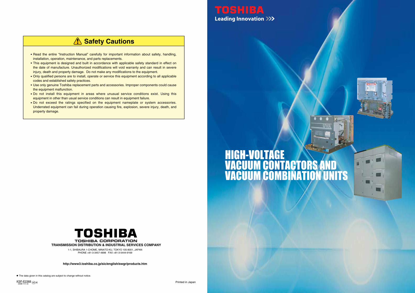
Safety Cautions Read the entire “Instruction Manual” carefully for important information about safety, handling, installation, operation, maintenance, and parts replacements. This equipment is designed and built in accordance with applicable safety standard in effect on the date of manufacture. Unauthorized modifications will void warranty and can result in severe injury, death and property damage. Do not make any modifications to the equipment. Only qualified persons are to install, operate or service this equipment according to all applicable codes and established safety practices. Use only genuine Toshiba replacement parts and accessories. Improper components could cause the equipment malfunction. Do not install this equipment in areas where unusual service conditions exist. Using this equipment in other than usual service conditions can result in equipment failure. Do not exceed the ratings specified on the equipment nameplate or system accessories. Underrated equipment can fail during operation causing fire, explosion, severe injury, death, and property damage. Printed in Japan The data given in this catalog are subject to change without notice. TRANSMISSION DISTRIBUTION & INDUSTRIAL SERVICES COMPANY KSP-E2368 4 2008-11 ( 1.5 ) AD 1-1, SHIBAURA 1-CHOME, MINATO-KU, TOKYO 105-8001, JAPAN PHONE +81-3-3457-4898 FAX +81-3-5444-9169 http://www3.toshiba.co.jp/sic/english/swgr/products.htm

Welcome message from author
This document is posted to help you gain knowledge. Please leave a comment to let me know what you think about it! Share it to your friends and learn new things together.
Transcript
Safety Cautions
Read the entire “Instruction Manual” carefully for important information about safety, handling, installation, operation, maintenance, and parts replacements.This equipment is designed and built in accordance with applicable safety standard in effect on the date of manufacture. Unauthorized modifications will void warranty and can result in severe injury, death and property damage. Do not make any modifications to the equipment.Only qualified persons are to install, operate or service this equipment according to all applicable codes and established safety practices.Use only genuine Toshiba replacement parts and accessories. Improper components could cause the equipment malfunction.Do not install this equipment in areas where unusual service conditions exist. Using this equipment in other than usual service conditions can result in equipment failure.Do not exceed the ratings specified on the equipment nameplate or system accessories. Underrated equipment can fail during operation causing fire, explosion, severe injury, death, and property damage.
Printed in Japan
The data given in this catalog are subject to change without notice.
TRANSMISSION DISTRIBUTION & INDUSTRIAL SERVICES COMPANY
KSP-E2368 42008-11(1.5)AD
1-1, SHIBAURA 1-CHOME, MINATO-KU, TOKYO 105-8001, JAPANPHONE +81-3-3457-4898 FAX +81-3-5444-9169
http://www3.toshiba.co.jp/sic/english/swgr/products.htm
Type-Form
Series
Type-Form
SeriesCompact and Lightweight
1 2
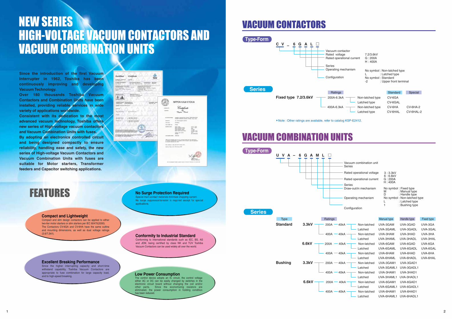
Since the introduction of the first Vacuum Interrupter in 1962, Toshiba has been continuously improving and developing Vacuum Technology. Over 180 thousands Toshiba Vacuum Contactors and Combination Units have been installed, providing reliable services in wide variety of applications worldwide.Consistent with its dedication to the most advanced vacuum technology, Toshiba offers new series of High-voltage vacuum contactors and Vacuum Combination Units with fuses. By adopting an electronics controlled circuit and being designed compactly to ensure reliability, handling ease and safety, the new series of High-voltage Vacuum Contactors and Vacuum Combination Units with fuses are suitable for Motor starters, Transformer feeders and Capacitor switching applications.
Compact and slim design contactors can be applied to either two-tier motor starters or slim starters per IEC 60470(2000). The Contactors CV-6GA and CV-6HA have the same outline and mounting dimensions, as well as dual voltage ratings (3.6/7.2kV).
Excellent Breaking PerformanceSince the higher interrupting capacity and short-time withstand capability, Toshiba Vacuum Contactors are appropriate to fuse combination for large capacity load, and to high-speed breaking.
No Surge Protection RequiredSpecial main contact materials minimize chopping current. No surge suppressor/arrester is required except for special applications.
Conformity to Industrial Standard
Low Power ConsumptionThe control device adopts an IC circuit, the control voltage either AC or DC can be easily changed by switches in the electronic circuit board without changing the coil and/or other parts. Since the economizing resistors are eliminated, the power consumption in holding condition has been reduced.
Vacuum contactorRated voltageRated operational current
SeriesOperating mechanism
Configuration
7.2/3.6kVG : 200AH : 400A
No symbol : Non-latched typeL : Latched typeNo symbol : Standard-2 : Upper front terminal
Vacuum combination unitSeries
Rated operational voltage
Rated operational current
SeriesDraw-out/in mechanism
Operating mechanism
Configuration
3 : 3.3kV 6 : 6.6kVG : 200AH : 400A
No symbol : Fixed typeM : Manual typeD : Handle typeNo symbol : Non-latched typeL : Latched type1 : Bushing type
Fixed type 7.2/3.6kV 200A-6.3kA Non-latched type CV-6GA
Latched type CV-6GAL
400A-6.3kA Non-latched type CV-6HA CV-6HA-2
Latched type CV-6HAL CV-6HAL-2
Standard Special
Standard 3.3kV 200A 40kA Non-latched UVA-3GAM UVA-3GAD UVA-3GA
Latched UVA-3GAML UVA-3GADL UVA-3GAL
400A 40kA Non-latched UVA-3HAM UVA-3HAD UVA-3HA
Latched UVA-3HAML UVA-3HADL UVA-3HAL
6.6kV 200A 40kA Non-latched UVA-6GAM UVA-6GAD UVA-6GA
Latched UVA-6GAML UVA-6GADL UVA-6GAL
400A 40kA Non-latched UVA-6HAM UVA-6HAD UVA-6HA
Latched UVA-6HAML UVA-6HADL UVA-6HAL
Bushing 3.3kV 200A 40kA Non-latched UVA-3GAM1 UVA-3GAD1
Latched UVA-3GAML1 UVA-3GADL1
400A 40kA Non-latched UVA-3HAM1 UVA-3HAD1
Latched UVA-3HAML1 UVA-3HADL1
6.6kV 200A 40kA Non-latched UVA-6GAM1 UVA-6GAD1
Latched UVA-6GAML1 UVA-6GADL1
400A 40kA Non-latched UVA-6HAM1 UVA-6HAD1
Latched UVA-6HAML1 UVA-6HADL1
Manual type Handle typeType Ratings
Ratings
Fixed type
Note : Other ratings are available, refer to catalog KSP-E2412.
Conforming to international standards such as IEC, BS, AS and JEM, being certified by class NK and TUV Toshiba Vacuum Contactors can be used widely all over the world.
3 4
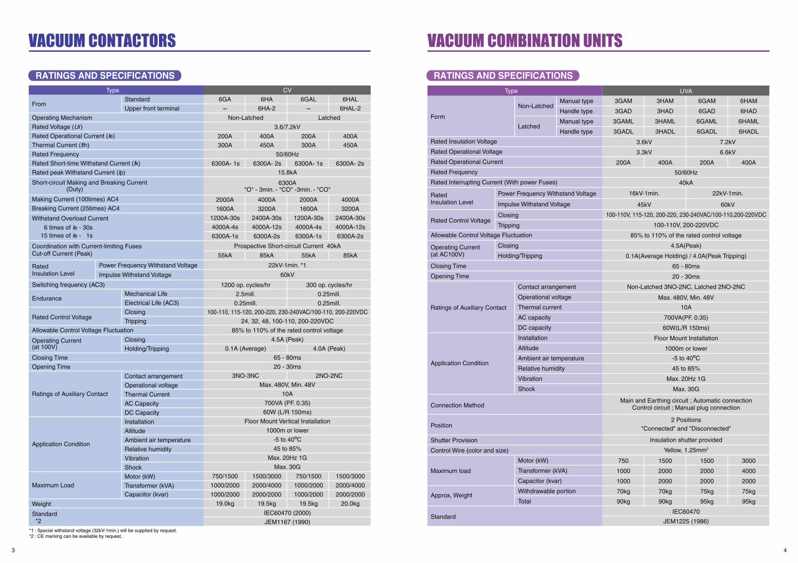
RATINGS AND SPECIFICATIONS RATINGS AND SPECIFICATIONS
*1 : Special withstand voltage (32kV-1min.) will be supplied by request.*2 : CE marking can be available by request.
From
RatedInsulation Level
Operating Current(at 100V)
Standard *2
Endurance
Rated Control Voltage
Allowable Control Voltage Fluctuation
Closing Time
Opening Time
Ratings of Auxiliary Contact
Application Condition
Maximum Load
Weight
Switching frequency (AC3)
Operating Mechanism
Rated Voltage (Ur)
Rated Operational Current (le)
Thermal Current (lth)
Rated Frequency
Rated Short-time Withstand Current (lk)
Rated peak Withstand Current (lp)
Short-circuit Making and Breaking Current (Duty)
Making Current (100times) AC4
Breaking Current (25times) AC4
Withstand Overload Current
6 times of le - 30s 15 times of le - 1s
Coordination with Current-limiting FusesCut-off Current (Peak)
Standard
Upper front terminal
6GA
-
300A
2000A
1600A
1200A-30s
4000A-4s
6300A-1s
55kA
750/1500
1000/2000
1000/2000
19.0kg
1500/3000
2000/4000
2000/2000
19.5kg
750/1500
1000/2000
1000/2000
19.5kg
1500/3000
2000/4000
2000/2000
20.0kg
4000A
3200A
2400A-30s
4000A-12s
6300A-2s
85kA
2000A
1600A
1200A-30s
4000A-4s
6300A-1s
55kA
4000A
3200A
2400A-30s
4000A-12s
6300A-2s
85kA
450A 300A 450A
200A 400A 200A 400A
6HA
6HA-2
3.6/7.2kV
50/60Hz
Prospective Short-circuit Current 40kA
15.8kA
6300A"O" - 3min. - "CO" -3min. - "CO"
1200 op. cycles/hr
2.5mill.
0.25mill.
300 op. cycles/hr
0.25mill.
0.25mill.
0.1A (Average) 4.0A (Peak)
3NO-3NC 2NO-2NC
22kV-1min. *1
60kV
100-110, 115-120, 200-220, 230-240VAC/100-110, 200-220VDC
24, 32, 48, 100-110, 200-220VDC
85% to 110% of the rated control voltage
4.5A (Peak)
65 - 80ms
20 - 30ms
Max. 480V, Min. 48V
10A
700VA (PF. 0.35)
60W (L/R 150ms)
Floor Mount Vertical Installation
1000m or lower
-5 to 40OC
45 to 85%
Max. 20Hz 1G
Max. 30G
IEC60470 (2000)
JEM1167 (1990)
Non-Latched Latched
6GAL
-
6HAL
6HAL-2
Impulse Withstand Voltage
Power Frequency Withstand Voltage
Mechanical Life
Electrical Life (AC3)
Closing
Tripping
Closing
Holding/Tripping
Contact arrangement
Operational voltage
Thermal Current
AC Capacity
DC Capacity
Installation
Altitude
Ambient air temperature
Relative humidity
Vibration
Shock
Motor (kW)
Transformer (kVA)Capacitor (kvar)
Type UVA
Manual type
Handle type
Manual type
Handle type
3GAM
3GAD
3GAML
3GADL
200A 400A
50/60Hz
40kA
100-110V, 115-120, 200-220, 230-240VAC/100-110,200-220VDC
100-110V, 200-220VDC
85% to 110% of the rated control voltage
4.5A(Peak)
0.1A(Average Holding) / 4.0A(Peak Tripping)
65 - 80ms
20 - 30ms
Non-Latched 3NO-2NC, Latched 2NO-2NC
Max. 480V, Min. 48V
10A
700VA(PF. 0.35)
60W(L/R 150ms)
Floor Mount Installation
1000m or lower
-5 to 40OC
45 to 85%
Max. 20Hz 1G
Max. 30G
750
1000
1000
70kg
90kg
1500
2000
2000
70kg
90kg
1500
2000
2000
75kg
95kg
IEC60470
JEM1225 (1986)
3000
4000
2000
75kg
95kg
2 Positions"Connected" and "Disconnected"
Insulation shutter provided
Yellow, 1.25mm2
Main and Earthing circuit ; Automatic connectionControl circuit ; Manual plug connection
200A 400A
3.6kV
3.3kV
16kV-1min. 22kV-1min.
45kV 60kV
7.2kV
6.6kV
3HAM
3HAD
3HAML
3HADL
6GAM
6GAD
6GAML
6GADL
6HAM
6HAD
6HAML
6HADL
Non-Latched
Power Frequency Withstand Voltage
Closing
Tripping
Contact arrangement
Operational voltage
Thermal current
AC capacity
DC capacity
Installation
Altitude
Ambient air temperature
Relative humidity
Vibration
Shock
Motor (kW)
Transformer (kVA)
Capacitor (kvar)
Withdrawable portion
Total
Closing
Holding/Tripping
Form
Rated Insulation Voltage
Rated Operational Voltage
Rated Operational Current
Rated Frequency
Rated Interrupting Current (With power Fuses)
Closing Time
Opening Time
Position
Shutter Provision
Control Wire (color and size)
Maximum load
Approx, Weight
Standard
RatedInsulation Level
Operating Current(at AC100V)
Impulse Withstand Voltage
Rated Control Voltage
Allowable Control Voltage Fluctuation
Ratings of Auxiliary Contact
Application Condition
Connection Method
Latched
Type CV
6300A- 1s 6300A- 2s 6300A- 1s 6300A- 2s

5 6
Fig. 1 Capacitor Switching Life (with 6% reactor)
APPLICATION AND SELECTION NOTICE FOR APPLICATION
OPERATING COIL EXCITATION
PROTECTION COORDINATION
Mainly applied to frequent switching operation such as motor.
Mainly applied to non-frequent switching operation and/or to the important load which
require to be contact closed even by power loss.
The protection coordination with upper/lower stream relay shall be evaluated by considering total system and load
characteristics.
The single-phase protection shall be performed which may be occurred by power fuses.
(Apply 2E-relay or fuse blown detection which is provided on combination unit as standard.)
TERMINAL CONNECTIONEither terminals, upper or lower, can be used for power or load side on contactor.
The upper terminals shall be connected to power side on combination unit for the protection coordination.
CONTROL TRANSFORMERThe contactor can be operated with following burden of control transformer.
CAPACITOR APPLICATIONThe current limiting fuses shall be combined for capacitor switching application.
The series reactor shall be connected, especially back-to-back application.
Service life of capacitor switching
The switching, opening and closing, of capacitor produces severe condition for contactor, such as high
frequency inrush current and interpole recovery voltage higher than twice of normal voltage.
The criteria of maximum number of capacitor switching are shown in the figure below. The vacuum interrupters should be
replaced when the number of switching operations reached to point shown in figure.
The surge suppressor is composed of capacitor and series resistor, and is one of the most excellent protection mediums. The
device features suppression as well as a decrease of surge generation. Particularly being free from limitation on the number
of operating times, this device is suitable for protecting motors and transformer required performing frequent operations.
The surge arrester has no effect of suppressing the surge generation, this suppresses overvoltage to within a fixed level.
APPLICATION GUIDE TO SURGENo surge protection is required except for special application, however the insulation coordination shall be evaluated by following
table.
Non-Latched(Continuous Excitation)
Latched(Instantaneous Excitation)
The surge suppressor shall be installed for machine rated at
55kW or below, and/or be subject to inching operation.
The surge suppressor shall be installed between starting
contactor and autotransformer for machine started by
autotransformer.
The suppressor shall be installed for machine which has inferior
insulation.
The surge arrester shall be installed for transformer rated at
150kVA or below and exciting inrush is interrupted.
The installation of suppressor and insulation coordination shall
be evaluated when the low surge level apparatus are connected
on secondary circuit of transformer.
Refer to the clause for capacitor application.
NoticeProtectionLoad
Rotating Machine
Dry-type Transformer
Oil-immersed Transformer
Capacitor
Not required
Not required
Not required
Not required
Type Form (Contactor)
CV-6GA(L), 6HA(L)
Control Transformer
400VA or more
VT
100VA 10P10
10
20
30
40
50
100
20 30 50 100 200 300 400
Switching Current (A)
Sw
itc
hin
g L
ife
(T
ho
usa
nd
Op
.)
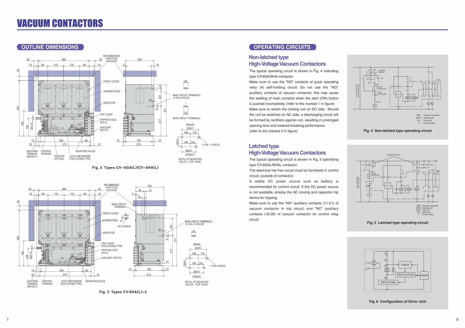
The typical operating circuit is shown in Fig. 4 indicating
type CV-6GA/6HA contactor.
Make sure to use the "NO" contacts of quick operating
relay (4) self-holding circuit. Do not use the "NO"
auxiliary contacts of vacuum contactor, this may cause
the welding of main contacts when the start (ON) button
is pushed incompletely. (refer to the marked 1 in figure)
Make sure to switch the closing coil on DC side. Should
the coil be switched on AC side, a discharging circuit will
be formed by rectifiers against coil, resulting in prolonged
opening time and lowered breaking performance.
(refer to the marked 2 in figure)
The typical operating circuit is shown in Fig. 5 specifying
type CV-6GAL/6HAL contactor.
The electrical trip free circuit must be furnished in control
circuit. (outside of contactor)
A stable DC power source such as battery is
recommended for control circuit. If the DC power source
is not available, employ the AC closing and capacitor trip
device for tripping.
Make sure to use the "NO" auxiliary contacts (11-21) of
vacuum contactor in trip circuit, and "NC" auxiliary
contacts (16-26) of vacuum contactor for control relay
circuit.
POWEROSCILLATION
TIMER
87
OUTLINE DIMENSIONS OPERATING CIRCUITS
Non-latched typeHigh-Voltage Vacuum Contactors
Latched type High-Voltage Vacuum Contactors
Fig. 2 Types CV-6GA(L)/CV-6HA(L)
Fig. 4 Non-latched type operating circuit
Fig. 5 Latched type operating circuit
Fig. 6 Configuration of Drive -Unit
Fig. 3 Types CV-6HA(L)-2
ONOFF
87
65
43
21
INDICATOR
LATCH MECHANISM(FOR LATCHED TYPE)
TRIP LEVER
TRIPPING HOLE(DIA 9)
MOUNTING HOLES
MAIN CIRCUIT TERMINALS12 DIA-6 HOLES
COUNTER(OPTION)
EARTHINGTERMINAL(M8 BOLT)
INTERRUPTERS
CONTROLTERMINAL
AUXILIARYSWITCH
MAIN CIRCUIT TERMINALS
FRONT COVER
RECOMMENDEDPARTITIONDISTANCE
(REAR)
(FRONT)
11 DIA - 4 HOLES
DETAIL OF MOUNTINGHOLES (TOP VIEW)
134166
166 179
180
30
3030 202
2 15
DIA
15
400
368
6969 115115 3113
10
66
124
217
128
6013
30
30
30018 373
10195219
1021 19
5+1
371
300+1
345+1-
-
-
87
65
43
21
ONOFF
195+
1
(REAR)
(FRONT)
300+1
345+1
134166
166 179
2118
13
373
60300
128
115 115
30
6
10 10195
215
124
621
7
371
10
10
21360
15
202
30
30 368
13 316969
400
DIA
-15
180
30
30
-
-
-
MOUNTING HOLESLATCH MECHANISM(FOR LATCHED TYPE)
CONTROL TERMINAL
EARTHING TERMINAL (M8 BOLT)
INDICATOR
M10 SCREW
FRONT COVER
INTERRUPTERS
TRIPPING HOLE(DIA 9)
TRIP LEVER(FOR LATCHED TYPE)
AUXILIARY SWITCH
MAIN CIRCUITTERMINALS
DETAIL OF MOUNTINGHOLES (TOP VIEW)
11 DIA-4 HOLES
MAIN CIRCUIT TERMINALS12 DIA-3 HOLES
RECOMMENDEDPARTITIONDISTANCE
20
0-2
20
VD
C1
00
-11
0V
DC
N
P
STARTINTERLOCK
COS
ONE E
4
26
16
D
2
DU
13
REMOTE SWITCH
SWITCHING
5 2CC
6
5
4
3
2
1
INTERLOCKSTOP
INTERLOCKSTART
SWITCHREMOTE
ON
10
0-1
10
VA
C/D
C2
00
-22
0V
AC
/DC
N or T
P or R
*1
4 COS
OFF
E
E
E
E
4
2E-RY
3
52CC
5
6
4
4
52TC25
15
2E-RYOFF
52CC
E E
2124
1411
7
RLGL
VMC
2223
1213
52TC
4DU
52CCVMC
: Trip coil
: Control relay: Drive unit
: Closing coil: Vacuum contactor
6
2
RLGL
4DU
52CCVMC
: Control relay: Drive unit: Closing coil: Vacuum contactor
VMC
5
52CC52CC
DU
4
41
212223242526
111213141516
*2
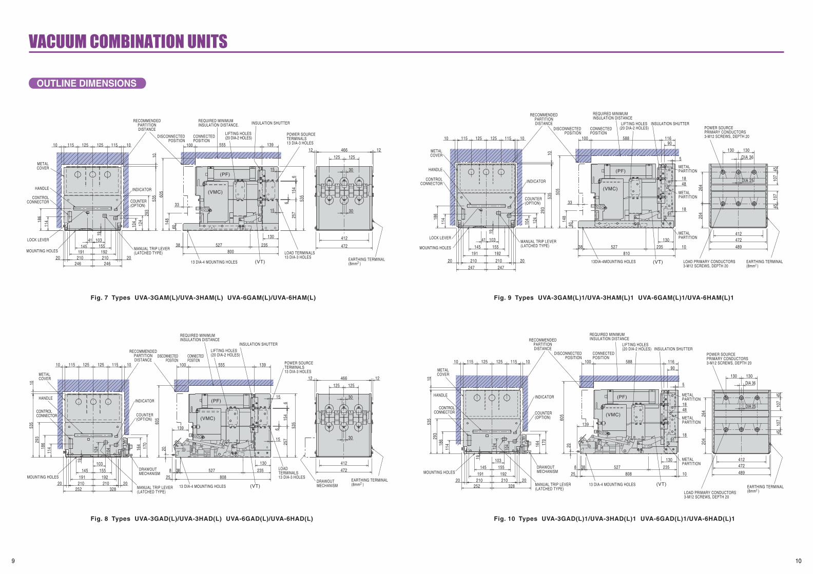
OUTLINE DIMENSIONS
9 10
Fig. 7 Types UVA-3GAM(L)/UVA-3HAM(L) UVA-6GAM(L)/UVA-6HAM(L)
Fig. 8 Types UVA-3GAD(L)/UVA-3HAD(L) UVA-6GAD(L)/UVA-6HAD(L)
Fig. 9 Types UVA-3GAM(L)1/UVA-3HAM(L)1 UVA-6GAM(L)1/UVA-6HAM(L)1
Fig. 10 Types UVA-3GAD(L)1/UVA-3HAD(L)1 UVA-6GAD(L)1/UVA-6HAD(L)1
(VMC)
(PF)
EARTHING TERMINAL(8mm2 )
POWER SOURCETERMINALS13 DIA-3 HOLES
LOAD TERMINALS13 DIA-3 HOLES
(VT)13 DIA-4 MOUNTING HOLES
INSULATION SHUTTER
LIFTING HOLES(20 DIA-2 HOLES)
REQUIRED MINIMUMINSULATION DISTANCE.
CONNECTEDPOSITION
DISCONNECTEDPOSITION
RECOMMENDEDPARTITIONDISTANCE
INDICATOR
COUNTER(OPTION)
MANUAL TRIP LEVER(LATCHED TYPE)MOUNTING HOLES
LOCK LEVER
HANDLE
CONTROLCONNECTOR
METALCOVER
555 13912 12466
293
19
472
30
30
125125
412
186
114
210246246
191
10341155145
210
535
115125125115
3315
15
6
6
535
154
257
80023552738
130
124
104
19220
148
10 10
1060
5
20
60
100
DRAWOUT MECHANISM
(VMC)
(PF)
POWER SOURCE TERMINALS13 DIA-3 HOLES
INSULATION SHUTTER
LIFTING HOLES (20 DIA-2 HOLES)CONNECTED
POSITIONDISCONNECTED
POSITION
REQUIRED MINIMUMINSULATION DISTANCE
RECOMMENDEDPARTITIONDISTANCE
(VT)
DRAWOUT MECHANISM
COUNTER (OPTION)
INDICATOR
EARTHING TERMINAL (8mm2 )
LOAD TERMINALS13 DIA-3 HOLES
MANUAL TRIP LEVER (LATCHED TYPE)
MOUNTING HOLES
CONTROL CONNECTOR
HANDLE
METAL COVER
13 DIA-4 MOUNTING HOLES
170
10 10
1212
115125125115
1053
5 605
139555100
130
235
139
25 808
15
15
6
6
20
8 38 527
154
257
535
20 20
472
466
293
19
328252210210
145191
155192
103
164
124
10418
611
4
30
30
125125
412
METALPARTITION
(VMC)
(PF)
METALPARTITION
LOAD PRIMARY CONDUCTORS3-M12 SCREWS, DEPTH 20
EARTHING TERMINAL(8mm2 )
METALPARTITIONCOUNTER
(OPTION)
INDICATOR
RECOMMENDEDPARTITIONDISTANCE
DISCONNECTEDPOSITION
CONNECTEDPOSITION
REQUIRED MINIMUMINSULATION DISTANCE
LIFTING HOLES(20 DIA-2 HOLES)
INSULATION SHUTTERPOWER SOURCEPRIMARY CONDUCTORS3-M12 SCREWS, DEPTH 20
(VT)13DIA-4MOUNTING HOLES
MANUAL TRIP LEVER(LATCHED TYPE)MOUNTING HOLES
LOCK LEVER
CONTROLCONNECTOR
HANDLE
METALCOVER
4545
41219
293
DIA 25
DIA 36
107
107
130130
264
204
472
489
20 20
41
186
114
10
10 10
535
124
104
247 247210 210
192191145 155
103
115 115125125
33
91
5
4818
18
1038810
130
235527
148
60
505
11658810090
METALPARTITION
DRAWOUTMECHANISM
EARTHING TERMINAL(8mm2 )
(VT)13 DIA-4 MOUNTING HOLES
LIFTING HOLES(20 DIA-2 HOLES)
REQUIRED MINIMUMINSULATION DISTANCE
CONNECTEDPOSITION
DISCONNECTEDPOSITION
RECOMMENDEDPARTITIONDISTANCE
INDICATOR
COUNTER(OPTION)
MANUAL TRIP LEVER(LATCHED TYPE)
MOUNTING HOLES
HANDLE
CONTROLCONNECTOR
METALCOVER
LOAD PRIMARY CONDUCTORS3-M12 SCREWS, DEPTH 20
INSULATION SHUTTERPOWER SOURCEPRIMARY CONDUCTORS3-M12 SCREWS, DEPTH 20
(VMC)
(PF)
METALPARTITION
METALPARTITION
90
4545
10
412
DIA 25
DIA 36
107
107
130130
264
204
472489
91
5
4818
18
116588
170
10 10115125125115
1053
5 605
100
130
235
139
25 808
20
8 38 527
20 20
293
19
328252210210
145191
155192
103
164
124
10418
611
4
WVU
Load
Main Power Supply
TSR
52
PFF1F VT
52CC52CCD
T3
5
6
DU
T12T1 T13 T16T18T2
21
AUS11 12
22
13
23
1415
2426
16
25
LS4
T21T20
T19
T4 T10T8T7T6T15
LS1
52TC
T14
LS3
T17T23 T24T22
T5T11
L8
L4LS2
2EXOFFE E
INTERLOCKSTART
COS
ONE E
2EX2EX
4
2EDC
N
P
4
200
3274
7 101
65688123
8 - 1
0
65 81
818 53
95
28113
1010
468
20
32
3 Shaft
Cubicle Door
2 Interlock Pin
Shutting The Door Cancels The Interlock
1 Rod2 Interlock Pin
4 Name Plate for ON-OFF Indication
Mounting Hole of Combination Unit
7 Lock Lever
5 Interlock Lever6 Arm
5 Interlock Lever
3 Shaft
9 Rod Support
Small Door
8 Stopper
2 Interlock Pin (DIA 8)
Mounting Hole of Combination Unit
"B"
"A"
1 Rod
Hole
"E""D"
"C"
1 Rod
Depressing Position
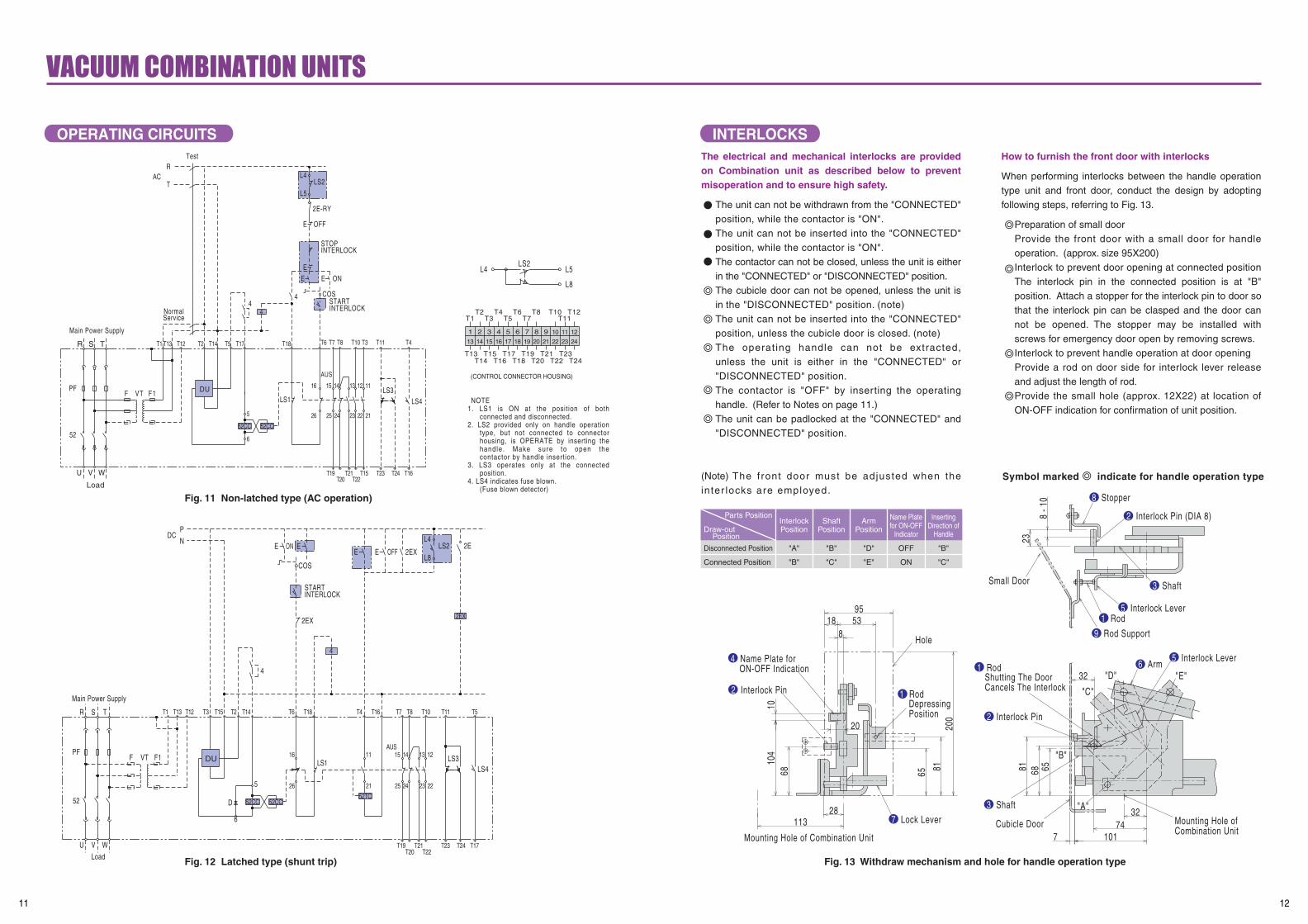
OPERATING CIRCUITS INTERLOCKS
11 12
The electrical and mechanical interlocks are provided on Combination unit as described below to prevent misoperation and to ensure high safety.
The unit can not be withdrawn from the "CONNECTED" position, while the contactor is "ON".The unit can not be inserted into the "CONNECTED" position, while the contactor is "ON".The contactor can not be closed, unless the unit is either in the "CONNECTED" or "DISCONNECTED" position.The cubicle door can not be opened, unless the unit is in the "DISCONNECTED" position. (note)The unit can not be inserted into the "CONNECTED" position, unless the cubicle door is closed. (note)The operating handle can not be extracted, unless the unit is either in the "CONNECTED" or "DISCONNECTED" position.The contactor is "OFF" by inserting the operating handle. (Refer to Notes on page 11.)The unit can be padlocked at the "CONNECTED" and "DISCONNECTED" position.
(Note) The front door must be adjusted when the inter locks are employed.
How to furnish the front door with interlocks
When performing interlocks between the handle operation type unit and front door, conduct the design by adopting following steps, referring to Fig. 13.
Preparation of small doorProvide the front door with a small door for handle operation. (approx. size 95X200)Interlock to prevent door opening at connected position The interlock pin in the connected position is at "B" position. Attach a stopper for the interlock pin to door so that the interlock pin can be clasped and the door can not be opened. The stopper may be installed with screws for emergency door open by removing screws.Interlock to prevent handle operation at door openingProvide a rod on door side for interlock lever release and adjust the length of rod.Provide the small hole (approx. 12X22) at location of ON-OFF indication for confirmation of unit position.
Symbol marked indicate for handle operation type
Fig. 11 Non-latched type (AC operation)
Fig. 12 Latched type (shunt trip) Fig. 13 Withdraw mechanism and hole for handle operation type
Parts Position
Draw-out Position
Disconnected Position
Connected Position
"A"
"B"
"B"
"C"
"D"
"E"
OFF
ON
"B"
"C"
InterlockPosition
ShaftPosition
ArmPosition
Name Platefor ON-OFF
Indicator
InsertingDirection of
Handle
ACT
RTest
INTERLOCKSTOP
L5
L4LS2
2E-RY
OFFE
T4T11T3T10T8T7T6
4
INTERLOCKSTART
COS
ONEE
E
T18
4
AUS
12131415
26
16
25
LS1
T15T21 T16T23 T24T22T20
T19WVU
52
PF
Load
F1F VT DU
ServiceNormal
Main Power Supply
T5T14T12
52CC
T1TSR T13 T2
5
6
T17
52CC
21
11
222324
LS4LS3
4
13 14 15 16 17 18 19 20 21 22 23 24
121110987654321
L8
L4 L5LS2
T13T14 T16 T18 T20 T22
T15 T17 T19 T21T24
T23
(CONTROL CONNECTOR HOUSING)
T1T2 T4 T6 T8
T3 T5 T7 T11T10 T12
NOTE1. LS1 is ON at the position of both
connected and disconnected.2. LS2 provided only on handle operation
type, but not connected to connector housing, is OPERATE by inserting the handle. Make sure to open the contactor by handle insertion.
3. LS3 operates only at the connected position.
4. LS4 indicates fuse blown.(Fuse blown detector)
(PF)
(VMC)
(PF)
POWER SOURCETERMINALS
LOAD TERMINALS
POWER FUSE(DOUBLE BARREL)
REQUIRED MINIMUMINSULATION DISTANCE
CONNECTEDPOSITION
DISCONNECTEDPOSITION
RECOMMENDEDPARTITIONDISTANCE
METALCOVER
555 139
B
A
293
115125125115
15
15
6
6
535
154
257
10 10
10
100
MOVABLE UNIT
45O
6520
25
907
74130
182
535
3 136
42 472
175
12 12466
808 EARTHINGTERMINAL(8mm2 )
EARTHINGWIRE
EARTHINGMECHANISM
EARTHINGCLIPS
DRAWOUTMECHANISM
DRAWOUTMECHANISM
INSULATION SHUTTER
605
55
15
15
66
154
257
535
12 455
479
436
114
190190
191
103
294
124
104
535
115125125115
192
19
9 946612512530
30
EARTHINGTERMINAL(8mm2)
RECOMMENDEDPARTITIONDISTANCE
12 DIA-4 MOUNTING HOLES (VT)
LOAD TERMINALS(13 DIA-3 HOLES)
POWER SOURCETERMINALS(13 DIA-3 HOLES)
LIFTING HOLES(20 DIA-2 HOLES)
REQUIRED MINIMUMINSULATION DISTANCE
INDICATOR
COUNTER(OPTION)
MANUAL TRIP LEVER(LATCHED TYPE)MOUNTING
HOLES
CONTROLCONNECTOR
METALCOVER
(VMC)
(PF)
10
10 10 543
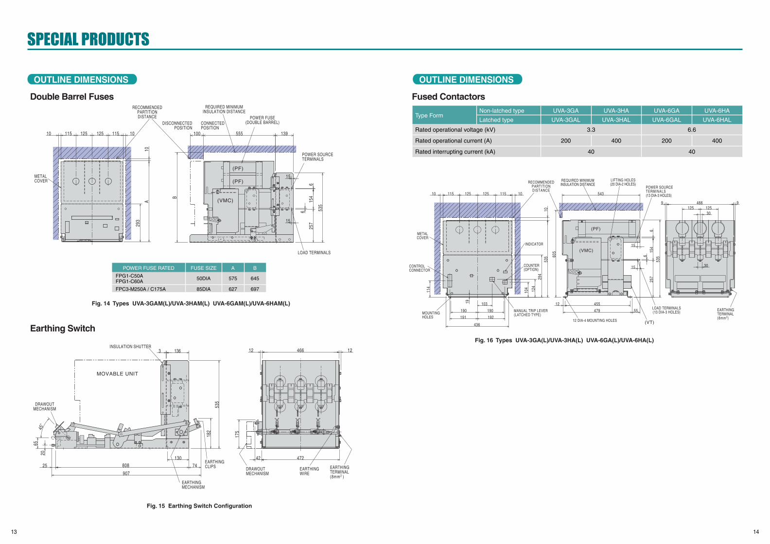
OUTLINE DIMENSIONS OUTLINE DIMENSIONS
13 14
Fig. 16 Types UVA-3GA(L)/UVA-3HA(L) UVA-6GA(L)/UVA-6HA(L)
Fig. 14 Types UVA-3GAM(L)/UVA-3HAM(L) UVA-6GAM(L)/UVA-6HAM(L)
Fig. 15 Earthing Switch Configuration
Double Barrel Fuses Fused Contactors
Earthing Switch
POWER FUSE RATED FUSE SIZE A B
FPG1-C50AFPG1-C60A
FPC3-M250A / C175A
50DIA
85DIA
575
627
645
697
Type FormNon-latched type
Latched type
UVA-3GA
UVA-3GAL
UVA-3HA
UVA-3HAL
UVA-6GA
UVA-6GAL
UVA-6HA
UVA-6HAL
Rated operational voltage (kV)
Rated operational current (A)
Rated interrupting current (kA)
3.3 6.6
40 40
200 400 200 400
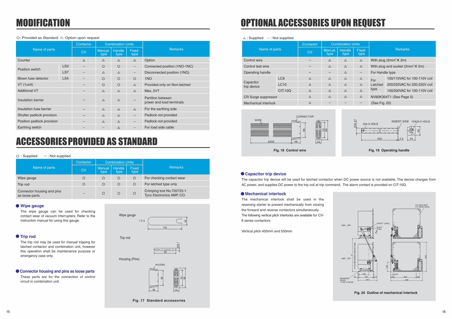
Wipe gaugeThe wipe gauge can be used for checking contact wear of vacuum interrupters. Refer to the instruction manual for using this gauge.
Trip rodThe trip rod may be used for manual tripping for latched contactor and combination unit, however this operation shall be maintenance purpose or emergency case only.
Connector housing and pins as loose partsThese parts are for the connection of control circuit in combination unit.
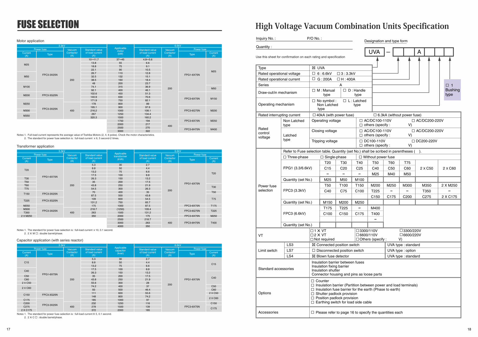
Mechanical interlockThe mechanical interlock shall be used in the
reversing starter to prevent mechanically from closing
the forward and reverse contactors simultaneously.
The following vertical pitch interlocks are available for CV-
6 series contactors.
Vertical pitch 450mm and 550mm
Capacitor trip deviceThe capacitor trip device will be used for latched contactor when DC power source is not available. The device charges from
AC power, and supplies DC power to the trip coil at trip command. The alarm contact is provided on CIT-10Q.
15
Fig. 18 Control wire
: Provided as Standard : Option upon request
Fig. 17 Standard accessories
Wipe gauge
Trip rod
Housing (Pins)
Name of parts RemarksContactor
CV
Combination Units
Manual type
Handle type
Counter Option
Connected position (1NO-1NC)
Disconnected position (1NO)
1NO
Provided only on Non-latched
Max. 2VT
For the earthing side
Padlock not provided
Padlock not provided
For load side cable
Partition betweenpower and load terminals
Fixed type
Position switch
Blown fuse detector
VT (1unit)
Additional VT
Insulation barrier
Insulation fuse barrier
Shutter padlock provision
Position padlock provision
Earthing switch
LS3
LS7
LS4
Name of parts Remarks
Contactor
CV
Combination Units
Manual type
Handle type
Wipe gauge
Trip rod
Connector housing and pinsas loose parts
For checking contact wear
For latched type only
Fixed type
Crimping tool No.720725-1Tyco Electronics AMP. CO.
Name of parts
Control wire
Control test wire
Operating handle
LC9
LC10
CIT-10Q
CR Surge suppressor
Mechanical interlock
Capacitortrip device
66
24
70 86
46
HOUSING
t 0.5 28
120
DIA
7
60
2000
WIRE
16
Fig. 19 Operating handle
Fig. 20 Outline of mechanical interlock
RemarksContactor
CV Manual type
Handle type
Fixed type
With plug (2mm2X 2m)
With plug and socket (2mm2X 2m)
For Handle type
NV60K304T1 (See Page 5)
(See Fig. 20)
100/110VAC for 100-110V coil
200/220VAC for 200-220V coil
100/200VAC for 100-110V coil
For Latchedtype
66
24
70
86
46
CONNECTOR
DIA
27
400 4.5
49
44
DIA 6 HOLEINSERT SIDE 10X20.5 HOLE
ONOFF
SHAFT (VMC)
8.8
O
CV-6GAL,6HALCV-6GA,6HA
MOUNTING HOLES11 DIA -4 HOLES
VMC : OFF
VMC : OFF
PIT
CH
BE
TWE
EN
CO
NTA
CTO
RS
10
40
0
12
8
426
4545 300
13
257
10 195
136
P
Combination Units
: Supplied : Not supplied
: Supplied : Not supplied
17 18
Motor application
Transformer application
Capacitor application (with series reactor)
Notes 1. Full-load current represents the average value of Toshiba Motors (2, 4, 6 poles). Check the motor characteristics.2. The standard for power fuse selection is : full-load current X 6, 5 second-2 times.
Notes 1. The standard for power fuse selection is : full-load current X 10, 0.1 second.2. 2 X M : double barrel/phase.
Notes 1. The standard for power fuse selection is : full-load current X 5, 0.1 second.2. 2 X C : double barrel/phase.
3.3kVPower fuse Power fuse
Current(A)
Current(A)Type Type
VacuumContactor
(A)
Standard valueof load current
(A)
Applicablemotor(kW)
6.6kV
Standard valueof load current
(A)
VacuumContactor
(A)
M25
M50
M100
M200
M250
M300
M350
FPC3-3X25N
FPC3-3G25N
FPC3-3X25N
200
400
10 11.713.818.822.126.732.538.548
74.192.1
102.6140.9171.9178
195.1216.2267
320.3
37 45557590
110132160200315400450630750800900
1000125015001750200025003000
4.8 5.66.69.1
10.512.815.118.423.736.946.151.370.682.189
97.6108.1134.4160.2194217270322
FPG1-6X75N
FPC3-6X75N
FPC3-6G75N
FPC3-6X75N
FPC3-6H75N
M25
M50
M150
M200
M250
M400
200
400
3.3kVPower fuse Power fuse
Current(A)
Current(A)Type Type
VacuumContactor
(A)
Standard valueof load current
(A)
Applicabletransformer
(kVA)
6.6kV
Standard valueof load current
(A)
VacuumContactor
(A)
T20
T30T50T60T75
T150
T225
M250M300T350
2 X M250
FPG1-6X75N
FPC3-3X25N
FPC3-3G25N
FPC3-3X25N
200
400
5.38.813.217.526.335
43.854.570
87.5109
131.2175
218.7263350
305075
100150200250300400500600750
1000(1250)15002000250030004000
2.74.46.68.8
13.217.521.926.335
43.854.565.787.5
109.4131.2175
218.7263350
FPG1-6X75N
FPC3-6X75N
FPC3-6G75N
FPC3-6X75N
FPC3-6H75N
T20
T30
T50
T75
T175
T225
M250
T400
200
400
3.3kVPower fuse Power fuse
Current(A)
Current(A)Type Type
VacuumContactor
(A)
Standard valueof load current
(A)
Applicablecapacitor
(kvar)
6.6kV
Standard valueof load current
(A)
VacuumContactor
(A)
C15
C40
C50C60
2 X C50
2 X C60
C150
C175C200C275
2 X C175
FPG1-6X75N
FPC3-3G25N
FPC3-3X25N
200
400
5.38.813.217.526.335
43.855.674.293111148185232278372
305075
100150200250300400500600800
1000125015002000
2.74.46.68.8
13.217.521.92837
46.455.674.297116139185
FPG1-6X75N
FPC3-6X75N
C15
C40
C50C60
2 X C50
2 X C60
C150
C175
200
Inquiry No. : P/O No. :
Quantity :
Designation and type form
AUVA
1Bushingtype
CounterInsulation barrier (Partition between power and load terminals)Insulation fuse barrier for the earth (Phase to earth)Shutter padlock provisionPosition padlock provisionEarthing switch for load side cable
Please refer to page 16 to specify the quantities each
Connected position switch
Disconnected position switch
Blown fuse detector
1 X VT2 X VTNot required
UVA
6 : 6.6kV 3 : 3.3kV
G : 200A H : 400A
Type
Rated operational voltage
Rated operational current
Series
Draw-out/in mechanism
Operating mechanism
Operating voltage AC/DC100-110V AC/DC200-220Vothers (specify : V)
Without power fuseThree-phase Single-phase
FPG1 (3.3/6.6kV)
Quantity (set No.)
FPC3 (3.3kV)
Quantity (set No.)
FPC3 (6.6kV)
Quantity (set No.)
Closing voltage AC/DC100-110V AC/DC200-220Vothers (specify : V)
Tripping voltage DC100-110V DC200-220Vothers (specify : V)
M : Manual type
40kA (with power fuse) 6.3kA (without power fuse)Rated interrupting current
Ratedcontrolvoltage
Power fuseselection
VT
Limit switch
Standard accessories
Options
Non Latchedtype
Latchedtype
Refer to Fuse selection table. Quantity (set No.) shall be scribed in parentheses ( ).
D : Handle type
No symbol : Non Latched type
L : Latched type
3300/110V 3300/220V6600/110V 6600/220VOthers (specify : V)
UVA type : standard
UVA type : option
UVA type : standard
Insulation barrier between fusesInsulation fixing barrierInsulation shutterConnector housing and pins as loose parts
A
T20
C15
-M25
T50
C40
M150
T175
C100
T30
C20
-M50
T100
C75
M200
T225
C150
T40
C25
-M100
T150
C100
M250
-C175
T50
C40
M25
M200
T225
C150
M400
T400
-
T60
C50
M40
M250
-C175
T75
C60
M50
M300
-C200
2 X C50
M350
T350
C275
2 X C60
2 X M250
-2 X C175
LS3
LS7
LS4
Use this sheet for confirmation on each rating and specification
Accessories
Related Documents