High Voltage Testing of Electrical Apparatus It is essential to ensure that the electrical equipment is capable of withstanding the over voltages that are met with in service. The over voltages may be either due to natural causes like lightning or system originated ones such as switching or power frequency transient voltages. Hence, testing for over voltages is necessary.

High Voltage Testing of Electrical Apparatus It is essential to ensure that the electrical equipment is capable of withstanding the over voltages that.
Dec 15, 2015
Welcome message from author
This document is posted to help you gain knowledge. Please leave a comment to let me know what you think about it! Share it to your friends and learn new things together.
Transcript
High Voltage Testing of Electrical ApparatusIt is essential to ensure that the electrical
equipment is capable of withstanding theover voltages that are met with in service. The
over voltages may be either due to natural causes like lightning or system originated ones such as switching or power frequency transient voltages.
Hence, testing for over voltages is necessary.
DefinitionsIn test codes and standard specifications, certain technical terms
are used to specify and define conditions or procedures. Hence, commonly used technical terms arc defined here before
the actual testing techniques are discussed.(a) Disruptive Discharge VoltageThis is defined as the voltage which produces the loss of
dielectric strength of an insulation. It is that voltage at which the electrical stress in the insulation causes a
failure which includes the collapse of voltage and passage of current.
In solids, this causes a permanent loss of strength, and in liquids or gases only temporary loss may be caused.
When a discharge takes place between two electrodes in a gas or a liquid or over a solid surface in air, it is called fiashover.
If the discharge occurs through a solid insulation it is called puncture.

(b) Withstand VoltageThe voltage which has to be applied to a test object under
specified conditions in a withstand test is called the withstand voltage
(c) Fifty Per Cent Flashover VoltageThis is the voltage which has a probability of 50% flashover,
when applied to a test object. This is normally applied in impulse tests in which the loss of insulation strength is temporary.
(d) Hundred Per Cent Flashover VoltageThe voltage that causes a flashover at each of its applications
under specified conditions when applied to test objects is specified as hundred per cent flashover voltage.
(e) Creepage Distance It is the shortest distance on the contour of the external surface of the insulator unit or between two metal fittings on the insulator.
(f) a.c. Test VoltagesAlternating test voltages of power frequency
should have a frequency range of 40 to 60 Hz and should be approximately sinusoidal.
(g) Impulse VoltagesImpulse voltages are characterized by polarity,
peak value, time to front and time to half the peak value after the peak .
(h) Reference Atmospheric ConditionsThe electrical characteristics of the insulators
and other apparatus are normally referred to the reference atmospheric conditions of temperature,pressure and absolute humidity.

Tests on InsulatorsThe tests that are normally conducted are usually
subdivided as (i) type tests, and (ii) the routine tests. Type tests are intended to prove or check the design
features and the quality. The routine tests are intended to check the quality of the
individual test piece.Type tests are done on samples when new designs or
design changes are introduced, whereas the routine tests are done to ensure the reliability of the individual test objects and quality and consistency of the materials used in their manufacture.
High voltage tests include (i) the power frequency tests, and (ii) impulse tests.
All the insulators are tested for both categories of test.

Power Frequency TestsDry and Wet Flashover Tests In these tests the a.c. voltage of power frequency is
applied across the insulator and increased at a uniform rate of about 2 per cent per second of 75% of the estimated test voltage, to such a value that a breakdown occurs along the surface of the insulator.
If the ,test is conducted under normal conditions without any rain or precipitation, it is called "dry flashover test".
(b) Wet and Dry Withstand Tests (One Minute) In these tests, the voltage specified in the relevant
specification is applied under dry or wet conditions for a period of one minute with an insulator mounted as in service conditions.
The test piece should withstand the specified voltage

Impulse Tests(a) Impulse Withstand Voltage Test This test is done by applying standard impulse
voltage of specified value under dry conditions with both positive and negative polarities of the wave.
If five consecutive waves do not cause a flashover or puncture, the insulator is deemed to have passed the test.
If two applications cause flashover, the object is deemed to have failed.
If there is only one failure, additional ten applications of the voltage wave are made.
If the test object has withstood the subsequent applications, it is said to have passed the test.
(b) Impulse Flashover Test The test is done as above with the specified
voltage.Usually, the probability of failure is determined
for 40% and 60% failure values or 20% and 80% failure values, since it is difficult to adjust the test voltage for the exact 50% flashover values. The average value of the upper and the lower limits is taken.
The insulator surface should not be damaged by these tests, but slight marking on its surface or chipping off of the cement is allowed.
(c) Pollution Testing Because of the problem of pollution of outdoor electrical
insulation and consequent problems of the maintenance of electrical power systems,
pollution testing is gaining importance. The normal types of pollution are
(i) dust,micro-organisms, bird secretions, flies, etc., (ii) industrial pollution like smoke,petroleum vapours, dust, and other deposits,
(iii) coastal pollution in which corrosive and hygroscopic salt layers are deposited on the insulator surfaces,
(iv) Desert pollution in which sand storms cause deposition of sand and dust layers,
(v) ice and fog deposits at high altitudes and in polar countries.
These pollutions cause corrosion,non-uniform gradients along the insulator strings and surface of insulators and also cause deterioration of the material.
Also, pollution causes partial discharges and radio interference.
Hence, pollution testing is important for extra high voltage systems
Testing of Bushings
Bushings are an integral component of high voltage machines. A bushing is used to bring high voltage conductors through the grounded tank or body of the electrical equipment without excessive potential gradients between the conductor and the edge of the hole in the body
Power Frequency Tests(a) Power Factor—Voltage Test In this test, the bushing is set up as in
service or immersed in oil. It is connected such that the line conductor goes to the high voltage side and the tank or earth portion goes to the detector side of the high voltage Schering bridge.
Voltage is applied up to the line value in increasing steps and then reduced.
The capacitance and power factor (or tan∂) are recorded at each step. The characteristic of power factor or tan∂ versus applied voltage is drawn. This is a normal routine test but sometimes may be conducted on percentage basis.
(b) Internal or Partial Discharge Test This test is intended to find the deterioration or failure due to internal discharges caused in the composite insulation of the bushing. This is done by using internal or partial discharge arrangement .The voltage versus discharge magnitude as well as the quadratic rate gives an excellent record of the performance of the bushing in service. This is now a routine test for high voltage bushings
(c) Momentary Withstand Test at Power Frequency. The bushing has to withstand without flashover or puncture for a minimum time (~ 3Os) to measure the voltage. At present this test is replaced by the impulse withstand test.
(d) One Minute Wet Withstand Test at Power Frequency The most common and routine tests used for all electrical apparatuses are the one minute wet, and dry voltage withstand tests. In wet test, voltage specified is applied to the bushing mounted as in service with the rain arrangement as described earlier. A properly designed bushing has to withstand the voltage without flashover for one minute. This test really does not give any information for its satisfactory performance in service, while impulse and partial discharge tests give more information.
(e) Visible Discharge Test at Power Frequency This test is intended for determining whether the bushing is likely to give radio interference in service, when the voltage is applied. No discharge other than that from the arcing horns or grading rings should be visible to the observers in a dark room. The test arrangement is the same as that of the withstand test, but the test is conducted in a dark room.
Thermal Tests(a) Temperature Rise and Thermal Stability Tests The purpose of these tests is to ensure that the bushing in service for long does not have an excessive temperature rise and also does not go into the "thermal runaway" condition of the insulation used.Temperature rise test is carried out in free air with an ambient temperature below 4O C at a rated power frequency (50 Hz) a.c. current. The steady temperature rise above the ambient air temperature at any part of the bushing should not exceed 45 C.The test is carried out for such a long time till the temperature is substantially constant,i.e. the increase in temperature rate is less than l°C/hr. Sometimes, the bushings have to be operated along with transformers, of which the temperature reached may exceed 8OC. This temperature is high enough to produce large dielectric losses and thermal instability. For high voltage bushings this is particularly important, and hence the thermal stability test is done for bushings rated for 132 kV and above.
The test is carried out with the bushing immersed in oil at a maximum temperature as in service,and the voltage applied is 86% of the nominal system voltage. This is approximately √2 times the working voltage of the bushing and hence the dielectric losses are about double the normal value. The additional losses account for the conductor ohmic losses.
It has been considered unnecessary to specify the thermal stability test for oil-impregnated paper bushings of low ratings; but for the large high voltage bushings (1600 A, 400 kV transformer bushings, etc.), the losses in the conductor may behigh enough to outweigh the dielectric losses.
The thermal stability tests are type tests. But in the case of large sized high voltage bushings, it may be necessary to make them routine tests.
TESTING OF CIRCUIT BREAKERS
Testing of circuit breakers is intended to evaluate (a) the
constructional and operational characteristics, and (b)
the electrical characteristics of the circuit which the
breaker has to interrupt or make.
The main tests conducted on the circuit breakers are
(i) the dielectric tests or overvoltage tests,
(ii) the temperature rise tests,
(iii) the mechanical tests, and
(Iv) the short circuit tests

Dielectric tests consist of overvoltage withstand tests of power frequency, lightning and switching impulse voltages. Tests are done for both internal and external insulation with the switch or circuit breaker in both the open and closed positions. In the open position, the test voltage levels are 15% higher than the test voltages used when the breaker is in closed position. As such there is always the possibility of line to ground flashover. To avoid this, the circuit breaker is mounted on insulators above the ground, and hence the insulation level of the body of the circuit breaker is raised
The impulse tests with the lightning
impulse wave of standard shape are done
in a similar manner as in the case of
insulators. In addition, the switching surge
tests with switching overvoltages are done
on circuit breakers and isolators to assess
their performance under over voltages due
to switching operations.

Impulse Tests
(a) Impulse Withstand Voltage Test This test is done by applying standard
impulse voltage of specified value with both positive and negative polarities
of the wave.
If five consecutive waves do not cause a flashover or puncture, the breaker
is deemed to have passed the test. If two applications cause flashover, the
breaker is deemed to have failed.
If there is only one failure, additional ten applications of the voltage wave
are made. If the breaker has withstood the subsequent applications, it is
said to have passed the test.
(b) Impulse Flashover Test The test is done as above with the specified
voltage. Usually, the probability of failure is determined for 40% and 60%
failure values or 20% and 80% failure values, since it is difficult to adjust the
test voltage for the exact 50% flashover values. The average value of the
upper and the lower limits is taken.
Short Circuit Tests
The most important tests carried out on circuit breakers are short circuit
tests, since these tests assess the primary performance of these devices, i.e.
their ability to safely interrupt the fault currents. These tests consists of
determining the making and breaking capacities at various load currents and
rated voltages.
The different methods of conducting short circuit tests are
(I) Direct Tests
(a) using a short circuit generator as the source
(b) using the power utility system or network as the source.
(II) Synthetic Tests

(a) Direct Testing in the Networks or in the Fields :Circuit breakers are
sometimes tested for their ability to make or break the circuit under normal
load conditions or under short circuit conditions in the network itself. This is
done during period of limited energy consumption or when the electrical
energy is diverted to other sections of the network which are not connected
to the circuit under test.
The advantages of field tests are:
(i) The circuit breaker is tested under actual conditions like those that
occur in a given network.
(ii) Special occasions like breaking of charging currents of long lines, very
short line faults, interruption of small inductive currents, etc. can be tested
by direct testing only.
(iii) to assess the thermal and dynamics effects of short circuit currents, to
study applications of safety devices, and to revise the performance test
procedures,etc.

The disadvantages are:(i) The circuit breaker can be tested at only a given rated voltage and networkcapacity.(ii) The necessity to interrupt the normal services and to test only at light loadconditions.(iii) Extra inconvenience and expenses in installation of controlling and measuringequipment in the field.
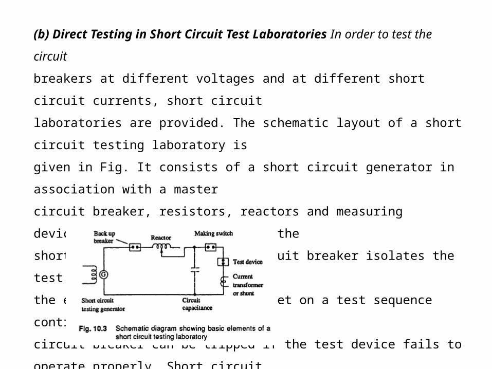
(b) Direct Testing in Short Circuit Test Laboratories In order to test the circuit
breakers at different voltages and at different short circuit currents, short circuit
laboratories are provided. The schematic layout of a short circuit testing laboratory is
given in Fig. It consists of a short circuit generator in association with a master
circuit breaker, resistors, reactors and measuring devices. A make switch initiates the
short circuit and the master circuit breaker isolates the test device from the source at
the end of a predetermined time set on a test sequence controller. Also, the master
circuit breaker can be tripped if the test device fails to operate properly. Short circuit
generators with induction motors as prime movers are also available.

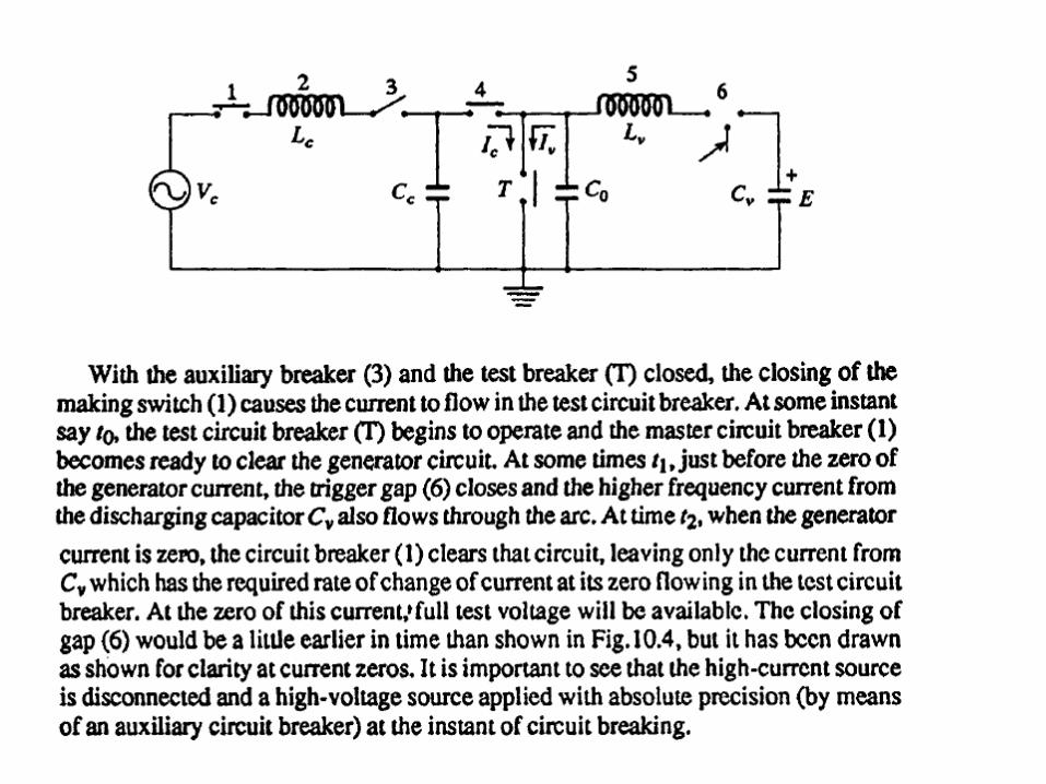
(c) Synthetic Testing of Circuit Breakers Due to very high interrupting capacities of circuit breakers, it is not economical to have a single source to provide the required short circuit and the rated voltage. Hence, the effect of a short circuit is obtained as regards to the intensity of the current and the recovery voltage as a combination of the effects of two sources, one of which supplies the a.c. current and the other the high voltage.
In the initial period of the short circuit test, the a.c. current source supplies the heavy current at a low voltage, and then the recovery voltage is simulated by a source of comparatively high voltage of small current capacity.
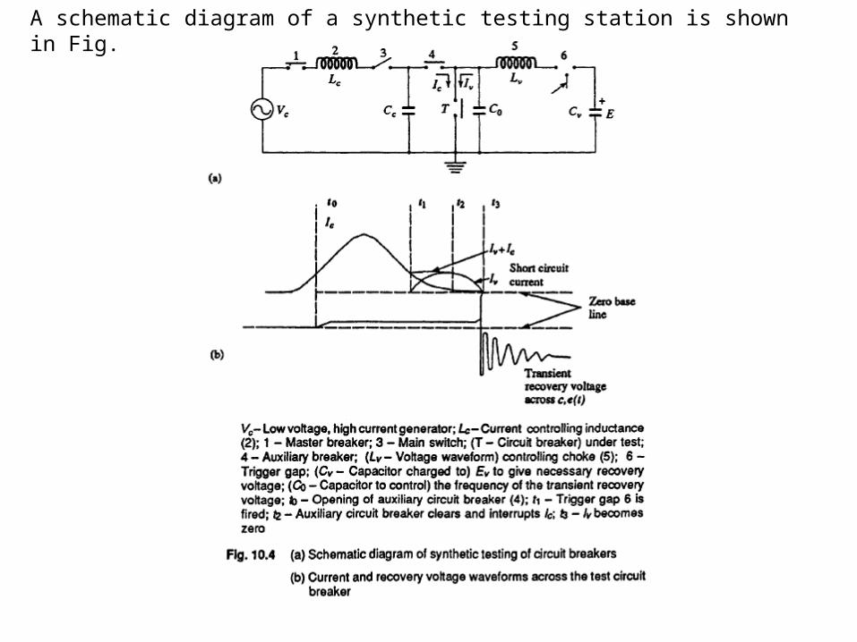
A schematic diagram of a synthetic testing station is shown in Fig.
(d) Composite Testing In this method, the breaker is first tested for its rated breaking capacity at a reduced voltage and afterwards for rated voltage at a low current. This method does not give a proper estimate of the breaker performance.
(e) Unit Testing When large circuit breakers of very high voltage rating (220 kV and above) are to be tested and where more than one break is provided per pole, the breaker is tested for one break at its rated current and the estimated voltage. In actual practice, the conditions of arc in each gap may not be identical and the voltage distribution along several breaks may be uneven. Hence, certain uncertainty prevails in the testing of one break.
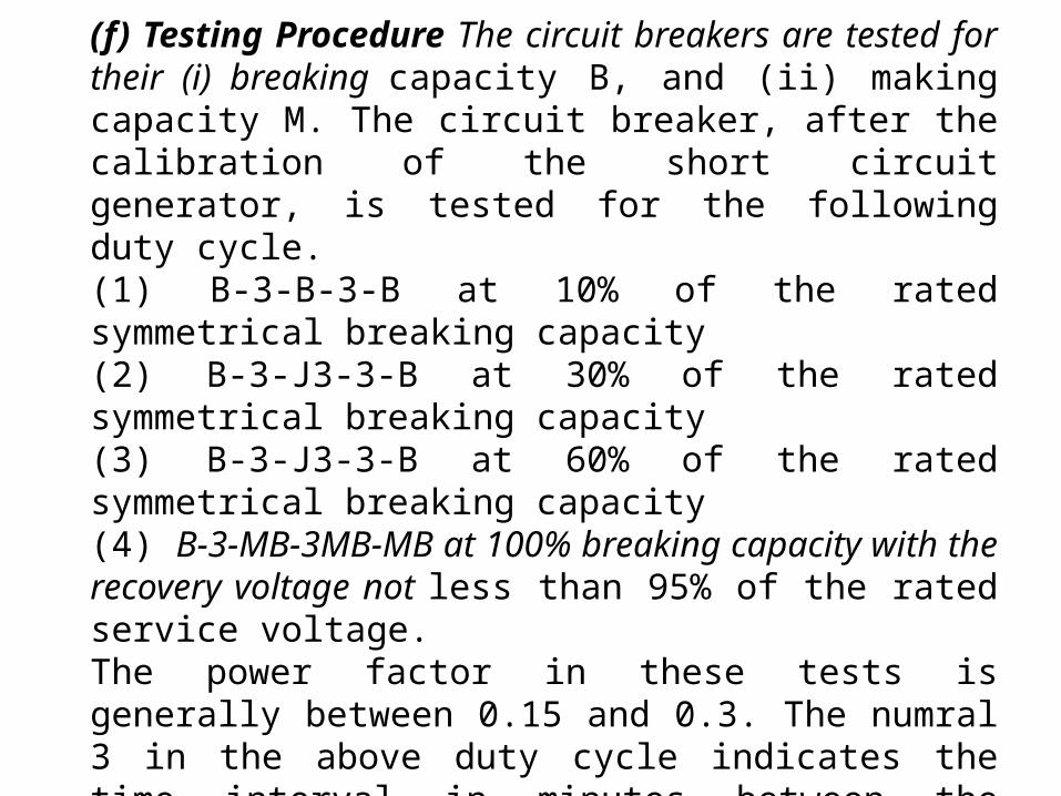
(f) Testing Procedure The circuit breakers are tested for their (i) breaking capacity B, and (ii) making capacity M. The circuit breaker, after the calibration of the short circuit generator, is tested for the following duty cycle.(1) B-3-B-3-B at 10% of the rated symmetrical breaking capacity(2) B-3-J3-3-B at 30% of the rated symmetrical breaking capacity(3) B-3-J3-3-B at 60% of the rated symmetrical breaking capacity(4) B-3-MB-3MB-MB at 100% breaking capacity with the recovery voltage not less than 95% of the rated service voltage.The power factor in these tests is generally between 0.15 and 0.3. The numral 3 in the above duty cycle indicates the time interval in minutes between the tests. (g) Asymmetrical Tests One test cycle is repeated for the asymmetrical breaking capacity in which the d.c. component at the instant of contact separation is not less than 50% of the a.c. component.
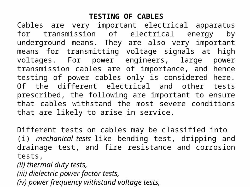
TESTING OF CABLESCables are very important electrical apparatus for transmission of electrical energy by underground means. They are also very important means for transmitting voltage signals at high voltages. For power engineers, large power transmission cables are of importance, and hence testing of power cables only is considered here. Of the different electrical and other tests prescribed, the following are important to ensure that cables withstand the most severe conditions that are likely to arise in service.
Different tests on cables may be classified into(i) mechanical tests like bending test, dripping and drainage test, and fire resistance and corrosion tests,(ii) thermal duty tests,(iii) dielectric power factor tests,(iv) power frequency withstand voltage tests,(v) impulse withstand voltage tests,(vi) partial discharge tests, and(vii) life expectancy tests.Here only the electrical tests are described, i.e. tests (iii) to (vii)

Dielectric Power Factor TestThe dielectric power factor test is done using the high voltage Schering bridge
The power factor or dissipation factor tan ∂ is measured at 0.5,1.0.1.66, and 2.0 times the rated voltage (phase to ground) of the cable.
The maximum value of the power factor and the difference in power factor between the rated voltage and 1.66 times the rated voltage, as well as, between the rated voltage and two times the rated voltage are specified.
The Schering bridge has to be given protection against overvoltages,in case breakdown occurs in the cables
High Voltage Tests on CablesCables are tested for withstand voltages using the power frequency a.c., d.c., and impulse voltages. At the time of manufacture, the entire cable is passed through a highvoltage test at the rated voltage to check the continuity of the cable. As a routine test,the cable is tested applying an a.c. voltage of 2.5 limes the rated value for 10 min. No damage to the cable insulation should occur. Type tests are done on cable samples using both high voltage d.c. and impulse voltages. The d.c. test consists of applying 1.8 times the rated d.c. voltage of negative polarity for 30 min., and the cable system is said to be fit, if it withstands the test. For impulse tests, impulse voltage of the prescribed magnitude as per specifications is applied, and the cable has to withstand five applications without any damage. Usually, after the impulse test, the power frequency dielectric power factor test is done to ensure that no failure occurred during the impulse test.

Partial DischargesPartial discharge is an electrical discharge that only partially bridges the dielectricor insulating medium between two conductors. Examples are: internal discharges,surface discharges and corona discharges.Internal discharges are discharges in cavities or voids which lie inside the volume of the dielectric or at the edges of conducting inclusions in a solid or liquid insulating media.Surface discharges are discharges from the conductor into a gas or a liquid medium and form on the surface of the solid insulation not covered by the conductor.Corona is a discharge in a gas or a liquid insulation around the conductors that areaway or remote from the solid insulation.
Discharge MeasurementPartial discharge measurements and the discharge locations are important for cables,since the life of the insulation at a given voltage stress depends on the internal discharges. Also, the weakness of the insulation or faults can be detected with the help of these tests; the portion of the cable if weak may be removed, if necessary.
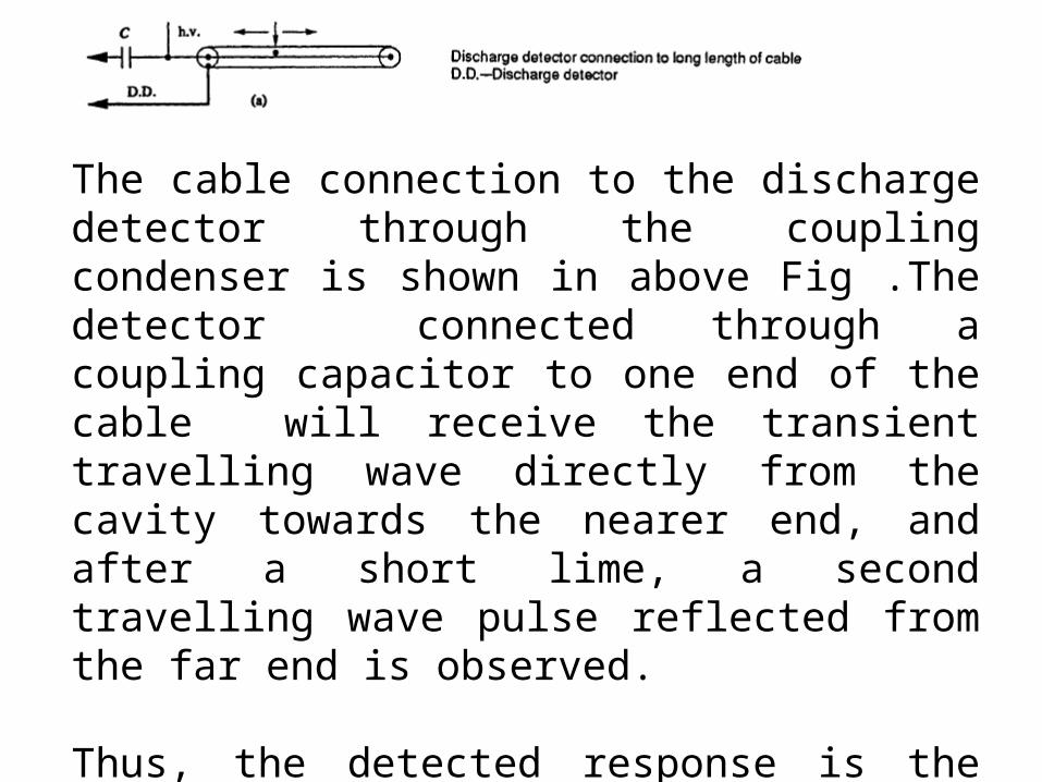
The cable connection to the discharge detector through the coupling condenser is shown in above Fig .The detector connected through a coupling capacitor to one end of the cable will receive the transient travelling wave directly from the cavity towards the nearer end, and after a short lime, a second travelling wave pulse reflected from the far end is observed.
Thus, the detected response is the combination of the above two transient pulses.
(b) Location of Discharges
The voltage dip caused by a discharge at a fault or a void is propagated as a travelling wave along the cable. This wave is detected as a voltage pulse across the terminals of the cable ends.
By measuring the time duration between the pulses, the distance at which the discharge is taking place from the cable end can be determined.
The shapes of the voltage pulses depend on the nature of the discharges.

The location of discharge is done using the travelling wave technique, The breakdown or discharge in a cavity at location F causes a charge accumulation at the fault point F. This creates two travelling waves which travel in opposite directions towards the cable ends.If the partial discharge site is located exactly in the middle of the cable, the travelling wave moving to the left is reflected without any polarity change at the open end and then arrives at the detection impedance, Zd, separated from the direct pulse by a time equal to the cable transit time T. If the site is at any other point, the time difference between the original pulse and its reflection may be any value from O to 2TBy knowing the transit time of the cable T and the actual time difference between the two pulses, the fault position can be located

(d) Life Tests
Life tests are intended for reliability studies in service. In order to determine theexpected life of the cable under normal stress, accelerated life tests using increased voltages are performed on actual cable lengths. It is established that the relation between the maximum electrical stress Em and the life of the cable insulation in hours t approximately follows the relationship
By conducting long duration life tests at increased stress (1 hr to about 1000 hr)the expected life at the rated stress may be determined.

TESTING OF TRANSFORMERSTransformers are very important and costly apparatus in power systems. Great care has to be exercised to see that the transformers are not damaged due to transient overvoltages of either lightning or power frequency. Hence, overvoltage tests become very important in the testing of transformers.
(a) Induced Overvoltage TestTransformers are tested for overvoltages by exciting the secondary of the transformer from a high frequency a.c. source (100 to 400 Hz) to about twice the rated voltage.This reduces the core saturation and also limits the charging current necessary in large power transformers. The insulation withstand strength can also be checked.
(b) Partial Discharge TestsPartial discharge tests on the windings are done to assess the discharge magnitudes and the radio interference levels The transformer is connected in a manner similar to any other equipment and the discharge measurements are made. The location of the fault or void is sometimes done by using the travelling wave technique similar to that for cables. So far, no method has been standardized as to where the discharge is to be measured. Multi-terminal partial discharge measurements are recommended. Under the application of power frequency voltage, the discharge magnitudes greater than 104 pico coulomb are considered to be severe, and the transformer insulation should be such that the discharge magnitude will be far below this value.
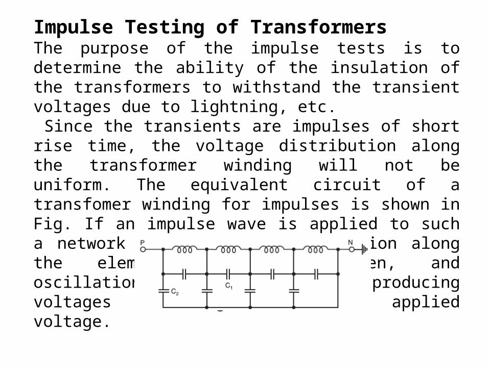
Impulse Testing of TransformersThe purpose of the impulse tests is to determine the ability of the insulation of the transformers to withstand the transient voltages due to lightning, etc. Since the transients are impulses of short rise time, the voltage distribution along the transformer winding will not be uniform. The equivalent circuit of a transfomer winding for impulses is shown in Fig. If an impulse wave is applied to such a network the voltage distribution along the element will be uneven, and oscillations will be set in producing voltages much higher than the applied voltage.
Here C1 represents inter-turn capacitance and C2 capacitance between winding and the ground (tank).
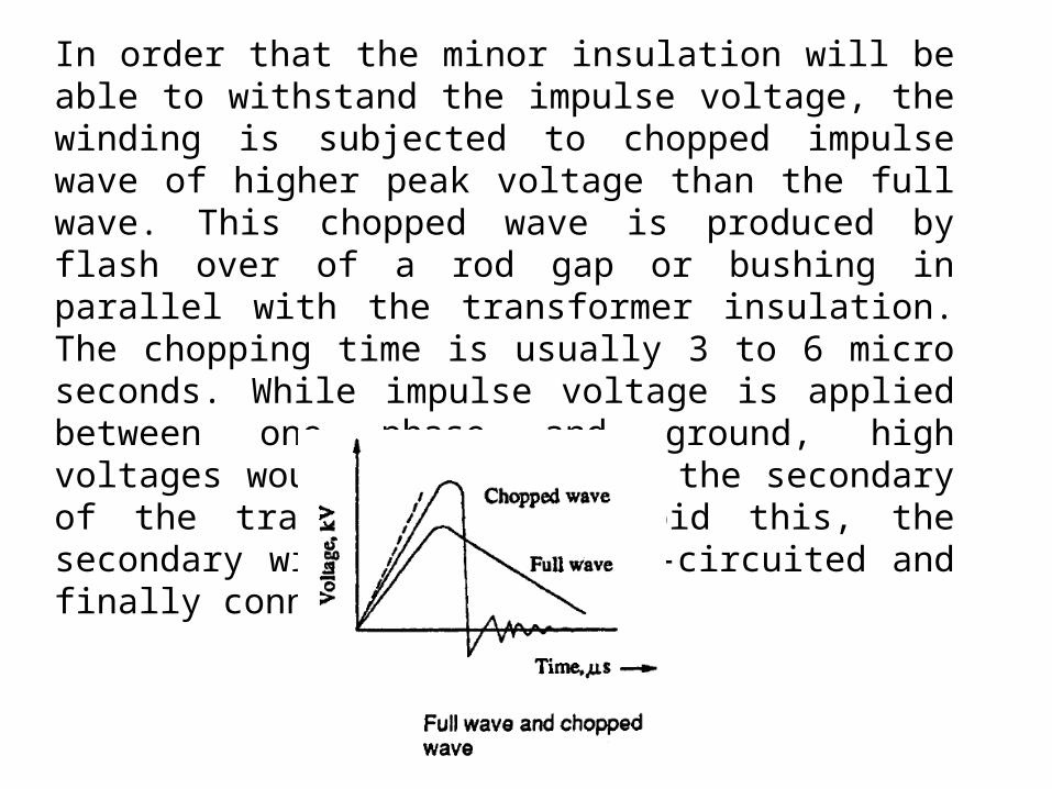
In order that the minor insulation will be able to withstand the impulse voltage, the winding is subjected to chopped impulse wave of higher peak voltage than the full wave. This chopped wave is produced by flash over of a rod gap or bushing in parallel with the transformer insulation. The chopping time is usually 3 to 6 micro seconds. While impulse voltage is applied between one phase and ground, high voltages would be induced in the secondary of the transformer. To avoid this, the secondary windings are short-circuited and finally connected to ground.
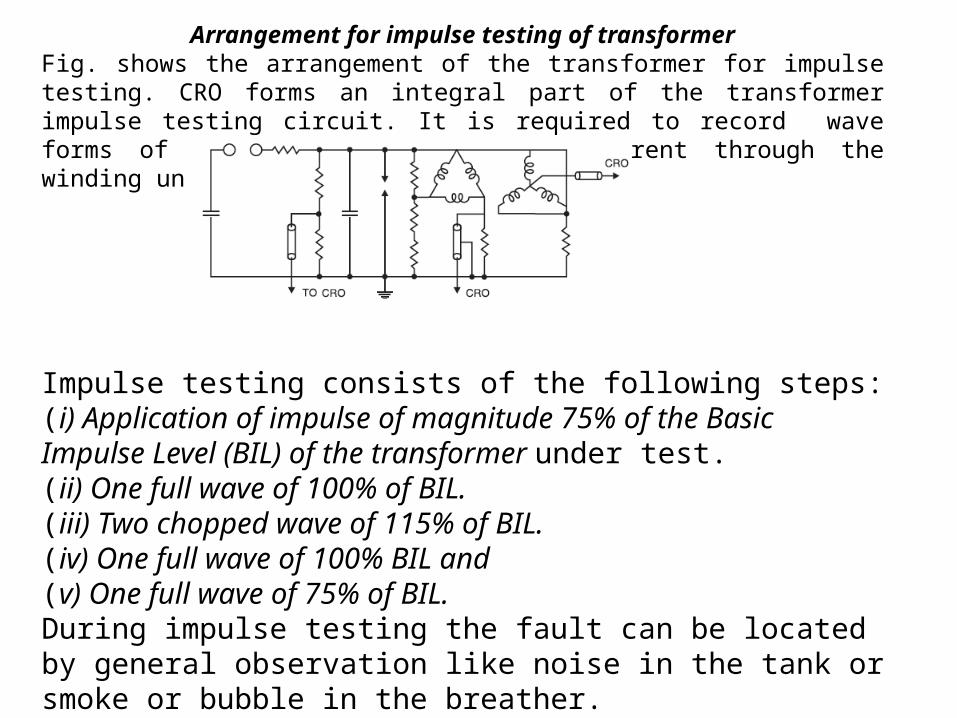
Arrangement for impulse testing of transformerFig. shows the arrangement of the transformer for impulse testing. CRO forms an integral part of the transformer impulse testing circuit. It is required to record wave forms of the applied voltage and current through the winding under test.
Impulse testing consists of the following steps:(i) Application of impulse of magnitude 75% of the Basic Impulse Level (BIL) of the transformer under test.(ii) One full wave of 100% of BIL.(iii) Two chopped wave of 115% of BIL.(iv) One full wave of 100% BIL and(v) One full wave of 75% of BIL.During impulse testing the fault can be located by general observation like noise in the tank or smoke or bubble in the breather.If there is a fault, it appears on the Oscilloscope as a partial of complete collapse of the applied voltage
Study of the wave form of the neutral current also indicated the type of fault. If an arc occurs between the turns or form turn to the ground, a train of high frequency pulses are seen on the oscilloscope and wave shape of impulse changes. If it is a partial discharge only, high frequency oscillations are observed but no change in wave shape occurs.
The bushing forms an important and integral part of transformer insulation. Therefore, its impulse flash over must be carefully investigated. The impulse strength of the transformer winding is same for either polarity of wave whereas the flash over voltage for bushing is different for different polarity. The manufacturer, however, while specifying the impulse strength of the transformer takes into consideration the overall impulse characteristic of the transformer.
Related Documents