Contact us Document ID 1HSM 9543 12-00en, High Voltage Surge Arresters, Byuer´s Guide, Edition 13, 2018-02 High Voltage Surge Arresters Buyer´s Guide

Welcome message from author
This document is posted to help you gain knowledge. Please leave a comment to let me know what you think about it! Share it to your friends and learn new things together.
Transcript
Contact us
Doc
umen
t ID
1H
SM
954
3 12
-00e
n, H
igh
Volta
ge S
urge
Arr
este
rs,
Byu
er´s
Gui
de,
Ed
ition
13,
201
8-02
High Voltage Surge ArrestersBuyer´s Guide
2 Product information | ABB Surge Arresters — Buyer´s Guide
Table of contents
Product informationIntroduction 3
Definitions 4
Simplified selection procedure 7
Design features - Porcelain-housed surge arresters, EXLIM 15
Design features - Polymer-housed surge arresters PEXLIM and TEXLIM 17
The PEXLINK concept 22
Quality control and testing 28
Technical informationPEXLIM — Zinc oxide surge arresters with silicone polymer-housed insulator:
PEXLIM R-Y, 10 kA, IEC arrester class designation SL 29
PEXLIM Q-Y, 10 kA, IEC arrester class designation SM 36
PEXLIM P-Z, 20 kA, IEC arrester class designation SH 43
PEXLIM P-Y, 20 kA, IEC arrester class designation SH 50
TEXLIM — High strength zinc oxide surge arresters with silicone polymer-housed insulator:
TEXLIM Q-C, 10 kA, IEC arrester class designation SM 56
TEXLIM P-C, 20 kA, IEC arrester class designation SH 63
TEXLIM T-C, 20 kA, IEC arrester class designation SH 69
EXLIM — Zinc oxide surge arresters with porcelain-housed insulator:
EXLIM R, 10 kA, IEC arrester class designation SL 75
EXLIM Q-E, 10 kA, IEC arrester class designation SM 81
EXLIM Q-D, 10 kA, IEC arrester class designation SM 88
EXLIM P, 20 kA, IEC arrester class designation SH 94
EXLIM T, 20 kA, IEC arrester class designation SH 102
Accessories:
Introduction 108
EXCOUNT-C 112
EXCOUNT-I 114
EXCOUNT-II 116
OtherPurchase order 119
Installations with ABB surge arresters 121
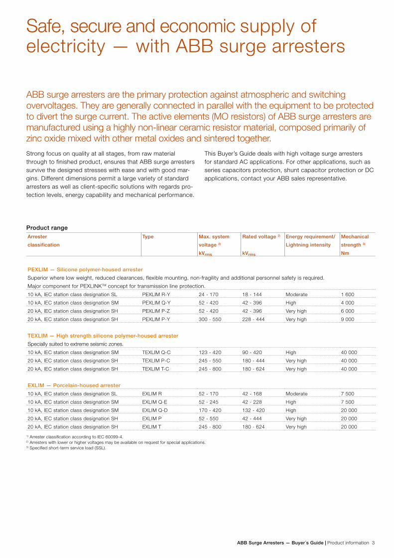
ABB Surge Arresters — Buyer´s Guide | Product information 3
Safe, secure and economic supply of electricity — with ABB surge arresters
Strong focus on quality at all stages, from raw material through to finished product, ensures that ABB surge arresters survive the designed stresses with ease and with good mar-gins. Different dimensions permit a large variety of standard arresters as well as client-specific solutions with regards pro-tection levels, energy capability and mechanical performance.
This Buyer’s Guide deals with high voltage surge arresters for standard AC applications. For other applications, such as series capacitors protection, shunt capacitor protection or DC applications, contact your ABB sales representative.
ABB surge arresters are the primary protection against atmospheric and switching overvoltages. They are generally connected in parallel with the equipment to be protected to divert the surge current. The active elements (MO resistors) of ABB surge arresters are manufactured using a highly non-linear ceramic resistor material, composed primarily of zinc oxide mixed with other metal oxides and sintered together.
Product rangeArrester
classification
Type Max. system
voltage 2)
kVrms
Rated voltage 2)
kVrms
Energy requirement/
Lightning intensity
Mechanical
strength 3)
Nm
PEXLIM — Silicone polymer-housed arrester
Superior where low weight, reduced clearances, flexible mounting, non-fragility and additional personnel safety is required.
Major component for PEXLINKTM concept for transmission line protection.
10 kA, IEC station class designation SL PEXLIM R-Y 24 - 170 18 - 144 Moderate 1 600
10 kA, IEC station class designation SM PEXLIM Q-Y 52 - 420 42 - 396 High 4 000
20 kA, IEC station class designation SH PEXLIM P-Z 52 - 420 42 - 396 Very high 6 000
20 kA, IEC station class designation SH PEXLIM P-Y 300 - 550 228 - 444 Very high 9 000
TEXLIM — High strength silicone polymer-housed arrester
Specially suited to extreme seismic zones.
10 kA, IEC station class designation SM TEXLIM Q-C 123 - 420 90 - 420 High 40 000
20 kA, IEC station class designation SH TEXLIM P-C 245 - 550 180 - 444 Very high 40 000
20 kA, IEC station class designation SH TEXLIM T-C 245 - 800 180 - 624 Very high 40 000
EXLIM — Porcelain-housed arrester
10 kA, IEC station class designation SL EXLIM R 52 - 170 42 - 168 Moderate 7 500
10 kA, IEC station class designation SM EXLIM Q-E 52 - 245 42 - 228 High 7 500
10 kA, IEC station class designation SM EXLIM Q-D 170 - 420 132 - 420 High 20 000
20 kA, IEC station class designation SH EXLIM P 52 - 550 42 - 444 Very high 20 000
20 kA, IEC station class designation SH EXLIM T 245 - 800 180 - 624 Very high 20 000 1) Arrester classification according to IEC 60099-4.2) Arresters with lower or higher voltages may be available on request for special applications.3) Specified short-term service load (SSL).
4 Product information | ABB Surge Arresters — Buyer´s Guide
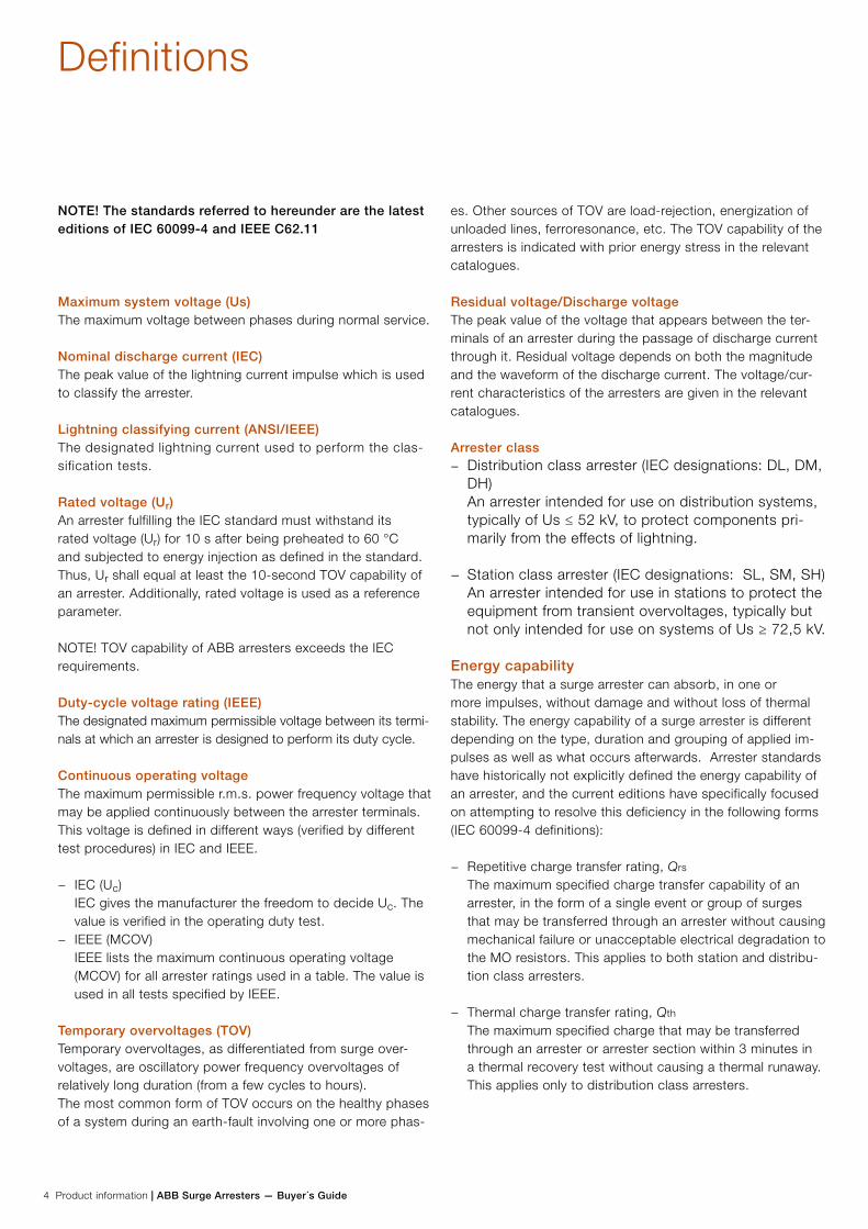
Definitions
NOTE! The standards referred to hereunder are the latest editions of IEC 60099-4 and IEEE C62.11
Maximum system voltage (Us)The maximum voltage between phases during normal service.
Nominal discharge current (IEC)The peak value of the lightning current impulse which is used to classify the arrester.
Lightning classifying current (ANSI/IEEE)The designated lightning current used to perform the clas-sification tests.
Rated voltage (Ur)An arrester fulfilling the IEC standard must withstand its rated voltage (Ur) for 10 s after being preheated to 60 °C and subjected to energy injection as defined in the standard. Thus, Ur shall equal at least the 10-second TOV capability of an arrester. Additionally, rated voltage is used as a reference parameter. NOTE! TOV capability of ABB arresters exceeds the IEC requirements.
Duty-cycle voltage rating (IEEE)The designated maximum permissible voltage between its termi-nals at which an arrester is designed to perform its duty cycle.
Continuous operating voltageThe maximum permissible r.m.s. power frequency voltage that may be applied continuously between the arrester terminals. This voltage is defined in different ways (verified by different test procedures) in IEC and IEEE.
− IEC (Uc) IEC gives the manufacturer the freedom to decide Uc. The value is verified in the operating duty test.
− IEEE (MCOV) IEEE lists the maximum continuous operating voltage (MCOV) for all arrester ratings used in a table. The value is used in all tests specified by IEEE.
Temporary overvoltages (TOV)Temporary overvoltages, as differentiated from surge over-voltages, are oscillatory power frequency overvoltages of relatively long duration (from a few cycles to hours). The most common form of TOV occurs on the healthy phases of a system during an earth-fault involving one or more phas-
es. Other sources of TOV are load-rejection, energization of unloaded lines, ferroresonance, etc. The TOV capability of the arresters is indicated with prior energy stress in the relevant catalogues.
Residual voltage/Discharge voltageThe peak value of the voltage that appears between the ter-minals of an arrester during the passage of discharge current through it. Residual voltage depends on both the magnitude and the waveform of the discharge current. The voltage/cur-rent characteristics of the arresters are given in the relevant catalogues.
Arrester class − Distribution class arrester (IEC designations: DL, DM,
DH) An arrester intended for use on distribution systems, typically of Us ≤ 52 kV, to protect components pri-marily from the effects of lightning.
− Station class arrester (IEC designations: SL, SM, SH) An arrester intended for use in stations to protect the equipment from transient overvoltages, typically but not only intended for use on systems of Us ≥ 72,5 kV.
Energy capabilityThe energy that a surge arrester can absorb, in one or more impulses, without damage and without loss of thermal stability. The energy capability of a surge arrester is different depending on the type, duration and grouping of applied im-pulses as well as what occurs afterwards. Arrester standards have historically not explicitly defined the energy capability of an arrester, and the current editions have specifically focused on attempting to resolve this deficiency in the following forms (IEC 60099-4 definitions):
− Repetitive charge transfer rating, Qrs The maximum specified charge transfer capability of an arrester, in the form of a single event or group of surges that may be transferred through an arrester without causing mechanical failure or unacceptable electrical degradation to the MO resistors. This applies to both station and distribu-tion class arresters.
− Thermal charge transfer rating, Qth The maximum specified charge that may be transferred through an arrester or arrester section within 3 minutes in a thermal recovery test without causing a thermal runaway. This applies only to distribution class arresters.
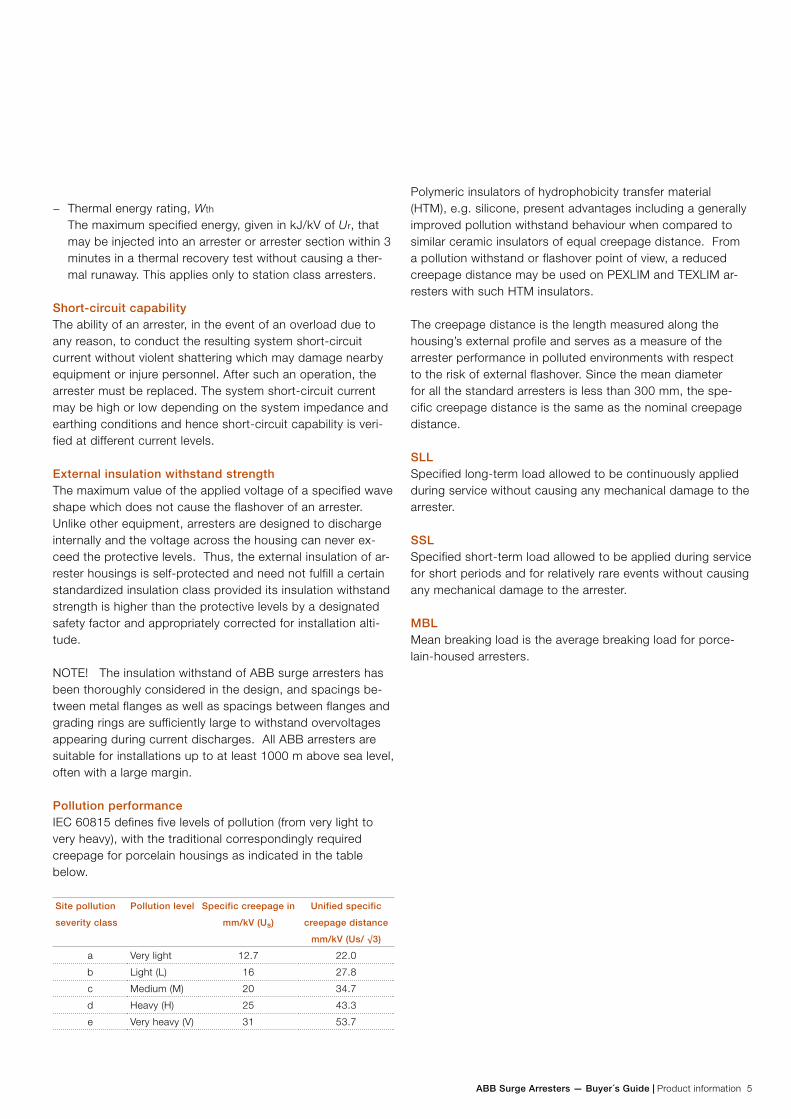
ABB Surge Arresters — Buyer´s Guide | Product information 5
− Thermal energy rating, Wth The maximum specified energy, given in kJ/kV of Ur, that may be injected into an arrester or arrester section within 3 minutes in a thermal recovery test without causing a ther-mal runaway. This applies only to station class arresters.
Short-circuit capabilityThe ability of an arrester, in the event of an overload due to any reason, to conduct the resulting system short-circuit current without violent shattering which may damage nearby equipment or injure personnel. After such an operation, the arrester must be replaced. The system short-circuit current may be high or low depending on the system impedance and earthing conditions and hence short-circuit capability is veri-fied at different current levels.
External insulation withstand strengthThe maximum value of the applied voltage of a specified wave shape which does not cause the flashover of an arrester. Unlike other equipment, arresters are designed to discharge internally and the voltage across the housing can never ex-ceed the protective levels. Thus, the external insulation of ar-rester housings is self-protected and need not fulfill a certain standardized insulation class provided its insulation withstand strength is higher than the protective levels by a designated safety factor and appropriately corrected for installation alti-tude.
NOTE! The insulation withstand of ABB surge arresters has been thoroughly considered in the design, and spacings be-tween metal flanges as well as spacings between flanges and grading rings are sufficiently large to withstand overvoltages appearing during current discharges. All ABB arresters are suitable for installations up to at least 1000 m above sea level, often with a large margin.
Pollution performanceIEC 60815 defines five levels of pollution (from very light to very heavy), with the traditional correspondingly required creepage for porcelain housings as indicated in the table below.
Site pollution
severity class
Pollution level Specific creepage in
mm/kV (Us)
Unified specific
creepage distance
mm/kV (Us/ √3)
a Very light 12.7 22.0
b Light (L) 16 27.8
c Medium (M) 20 34.7
d Heavy (H) 25 43.3
e Very heavy (V) 31 53.7
Polymeric insulators of hydrophobicity transfer material (HTM), e.g. silicone, present advantages including a generally improved pollution withstand behaviour when compared to similar ceramic insulators of equal creepage distance. From a pollution withstand or flashover point of view, a reduced creepage distance may be used on PEXLIM and TEXLIM ar-resters with such HTM insulators.
The creepage distance is the length measured along the housing’s external profile and serves as a measure of the arrester performance in polluted environments with respect to the risk of external flashover. Since the mean diameter for all the standard arresters is less than 300 mm, the spe-cific creepage distance is the same as the nominal creepage distance.
SLLSpecified long-term load allowed to be continuously applied during service without causing any mechanical damage to the arrester.
SSLSpecified short-term load allowed to be applied during service for short periods and for relatively rare events without causing any mechanical damage to the arrester.
MBLMean breaking load is the average breaking load for porce-lain-housed arresters.
6 Product information | ABB Surge Arresters — Buyer´s Guide
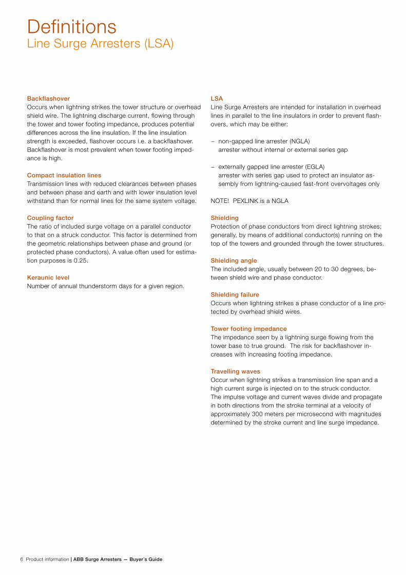
DefinitionsLine Surge Arresters (LSA)
BackflashoverOccurs when lightning strikes the tower structure or overhead shield wire. The lightning discharge current, flowing through the tower and tower footing impedance, produces potential differences across the line insulation. If the line insulation strength is exceeded, flashover occurs i.e. a backflashover. Backflashover is most prevalent when tower footing imped-ance is high.
Compact insulation linesTransmission lines with reduced clearances between phases and between phase and earth and with lower insulation level withstand than for normal lines for the same system voltage.
Coupling factorThe ratio of included surge voltage on a parallel conductor to that on a struck conductor. This factor is determined from the geometric relationships between phase and ground (or protected phase conductors). A value often used for estima-tion purposes is 0.25.
Keraunic levelNumber of annual thunderstorm days for a given region.
LSALine Surge Arresters are intended for installation in overhead lines in parallel to the line insulators in order to prevent flash-overs, which may be either:
− non-gapped line arrester (NGLA) arrester without internal or external series gap
− externally gapped line arrester (EGLA) arrester with series gap used to protect an insulator as-sembly from lightning-caused fast-front overvoltages only
NOTE! PEXLINK is a NGLA
ShieldingProtection of phase conductors from direct lightning strokes; generally, by means of additional conductor(s) running on the top of the towers and grounded through the tower structures.
Shielding angleThe included angle, usually between 20 to 30 degrees, be-tween shield wire and phase conductor.
Shielding failureOccurs when lightning strikes a phase conductor of a line pro-tected by overhead shield wires.
Tower footing impedanceThe impedance seen by a lightning surge flowing from the tower base to true ground. The risk for backflashover in-creases with increasing footing impedance.
Travelling wavesOccur when lightning strikes a transmission line span and a high current surge is injected on to the struck conductor. The impulse voltage and current waves divide and propagate in both directions from the stroke terminal at a velocity of approximately 300 meters per microsecond with magnitudes determined by the stroke current and line surge impedance.
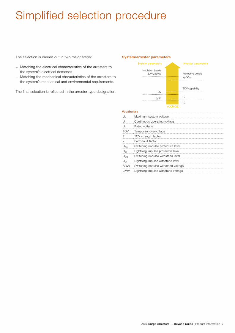
ABB Surge Arresters — Buyer´s Guide | Product information 7
System/arrester parameters
Vocabulary
Us Maximum system voltage
Uc Continuous operating voltage
Ur Rated voltage
TOV Temporary overvoltage
T TOV strength factor
k Earth fault factor
Ups Switching impulse protective level
Upl Lightning impulse protective level
Uws Switching impulse withstand level
Uwl Lightning impulse withstand level
SIWV Switching impulse withstand voltage
LIWV Lightning impulse withstand voltage
Simplified selection procedure
LIWV/SIWV
Us/√3
The selection is carried out in two major steps:
− Matching the electrical characteristics of the arresters to the system’s electrical demands
− Matching the mechanical characteristics of the arresters to the system’s mechanical and environmental requirements.
The final selection is reflected in the arrester type designation.
8 Product information | ABB Surge Arresters — Buyer´s Guide
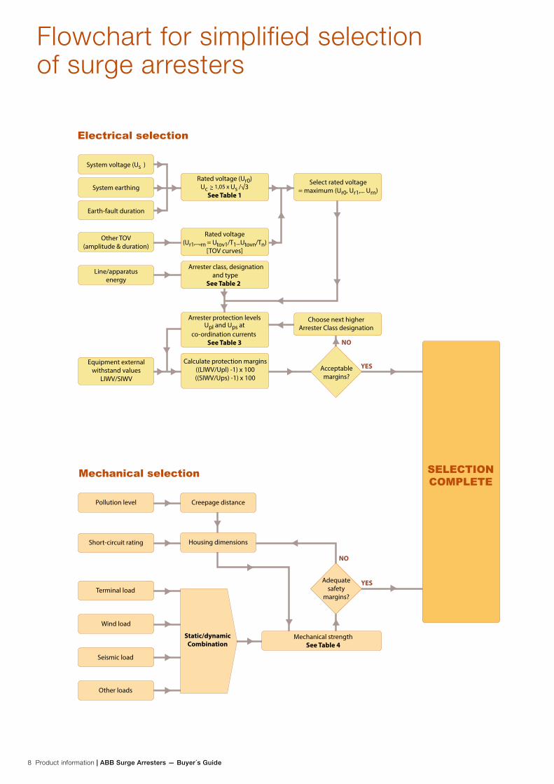
Flowchart for simplified selection of surge arresters
YES
YES
NO
NO
Static/dynamicCombination
SELECTIONCOMPLETE
System voltage (Us )
Rated voltage (Ur0)
See Table 1
Arrester class, designationand type
See Table 2
Arrester protection levelsUpl and Ups at
co-ordination currents See Table 3
Calculate protection margins((LIWV/Upl) -1) x 100((SIWV/Ups) -1) x 100
Rated voltage(Ur1,...,rn = Utov1/T1...Utovn/Tn)
[TOV curves]
Select rated voltage= maximum (Ur0, Ur1,... Urn)System earthing
Earth-fault duration
Other TOV(amplitude & duration)
Line/apparatusenergy
Short-circuit rating
Terminal load
Wind load
Seismic load
Other loads
Pollution level Creepage distance
Housing dimensions
Mechanical strengthSee Table 4
Choose next higherArrester Class designation
Equipment externalwithstand values
LIWV/SIWV
Acceptablemargins?
Adequatesafety
margins?
Electrical selection
Mechanical selection
Uc Us /√3> 1,05 x

ABB Surge Arresters — Buyer´s Guide | Product information 9
Matching the system characteristics
Arrester rated voltage (Ur)For each system voltage, the tables ”Guaranteed protective data” show a range of Ur and maximum continuous operating voltages Uc, all of which are capable of withstanding the ac-tual continuous operating voltage (Uca) with sufficient margin. Hence, the selection of Ur is only a function of the applied temporary overvoltages, TOV, (Utov), taking into account their amplitudes and duration.
TOV, as differentiated from surge overvoltages, are oscillatory power frequency overvoltages, with or without harmonics, of relatively long duration (from a few cycles to hours or longer) which are generated by system events. The arresters must withstand the heat energy generated by them.
Most commonly, a single or two-phase earth fault leads to a TOV in the healthy phase(s) and also in the neutral of Y-connected transformers. Its amplitude is determined by the system earthing conditions and its duration by the fault-clear-ance time.
If the earth-fault factor, (k) = Utov/Uca, is 1.4 or less, the system is considered to be effectively earthed. Generally, this implies a solid connection of the neutral to the earth grid. All other forms of earthing via an impedance or a non-earthing of the neutral is considered as non-effective with, typically, k = 1.73
For effectively earthed systems, the fault-clearance time is generally under 1 s but it can vary widely among different systems. The catalogues list the values of TOV capability for 1 and 10 s duration after a prior energy stress (as a conserva-tive approach). For other durations or for specific TOV condi-tions, follow the procedure hereunder:
− Consider each TOV separately. − From the TOV curves, read off the TOV strength factor (Tr)
for the time corresponding to the fault-clearance time. − Utov/Tr gives the minimum value of Ur for withstanding this
TOV. Choose the next higher standard rating. − The final choice of Ur will be the highest of the Ur values
obtained from the above calculations for each TOV.
System
earthing
Fault duration System voltage
Us (kV)
Min. Ur (kV)
Effective ≤ 10 s ≤ 100 ≥ 0.79 x Us
Effective ≤ 1 s ≥ 123 ≥ 0.74 x Us
Non-effective ≤ 10 s ≤ 170 ≥ 0.97 x Us
Non-effective ≤ 1 h ≤ 170 ≥ 1.24 x Us
Table 1.
The table gives a suggested minimum value of the arrester rated volt-
age (Ur). based on common parameters. In each case, choose the next
higher standard rating as given in the catalogue. This is only intended
as a general guide, and actual Ur necessary may depend on the specific
parameters of the system and the chosen arrester.
Note: Do not select a lower value of Ur than obtained as above unless the parameters are known more exactly; other-wise the arrester may be over-stressed by TOV.
Energy capability and Arrester Class designationIEC classifies arresters by their application and nominal discharge current. Station class 10 and 20 kA arresters are further classified by energy capability expressed as a repeti-tive charge transfer rating and thermal energy rating. These arresters are thereafter designated as either SL, SM, or SH where the letters “L”, “M” and “H” in the designation stand for “low”, “medium” and “high” duty, respectively.

10 Product information | ABB Surge Arresters — Buyer´s Guide
Arrester
Class
designation
Arrester type Energy capability Normal
application
range (Us)
Wth
kJ/kV (Ur) Qrs(C)
SL
EXLIM R 5 1.2 ≤ 170 kV
PEXLIM R-Z 5 1.2 ≤ 145 kV
PEXLIM R-Y 5 1.2 ≤ 170 kV
SM
EXLIM Q-E 8 2.0 ≤ 245 kV
EXLIM Q-D 8 2.0 170-420 kV
PEXLIM Q 8 2.0 ≤ 420 kV
TEXLIM Q-C 8 2.0 123-420 kV
SH
EXLIM P 11 3.2 ≤ 550 kV
PEXLIM P-Z 11 3.2 ≤ 420 kV
PEXLIM P-Y 11 3.2 300-550 kV
TEXLIM P-C 11 3.2 245-550 kV
EXLIM T 15 5.2 245-800 kV
TEXLIM T-C 15 5.2 245-800 kV
Table 2.
Energy capability of ABB arresters: The normal application range is only a
guide, and depends on the specific parameters.
Though the energy capability is mentioned in a different man-ner in IEEE, the normal range of application as above applies even for IEEE systems. For specific and special cases, e.g. capacitor banks, it may be necessary to calculate the energy capability differently; for example as shown in the IEC 60099-5 and other guides.
Protection levels (Upl and Ups)For insulation coordination purposes, consider the lightning impulse protection level (Upl) at 10 kA for Um ≤ 362 kV and at 20 kA for higher voltages. Similarly, the switching impulse protection levels (Ups) for coordination purposes range from 0.5 kA (for Um ≤ 170 kV) to 2 kA (for Um ≥ 362 kV). The values can be read-off from the catalogue tables or easily computed from Table 3. In the latter case, they must be rounded upwards.
Arrester type Nom.
Discharge
current (In)
Upl/Ur
at 10 kAp
Upl/Ur
at 20 kAp
Ups/Ur
EXLIM R 10 2.590 2.060 at 0.5 kAp
PEXLIM R-Y 10 2.590 2.060 at 0.5 kAp
EXLIM Q 10 2.350 1.981 at 1.0 kAp
PEXLIM Q 10 2.350 1.981 at 1.0 kAp
TEXLIM Q-C 10 2.350 1.981 at 1.0 kAp
EXLIM P 20 2.275 2.5 2.020 at 2.0 kAp
PEXLIM P-Z 20 2.250 2.5 2.020 at 2.0 kAp
PEXLIM P-Y 20 2.275 2.5 2.020 at 2.0 kAp
TEXLIM P-C 20 2.275 2.5 2.020 at 2.0 kAp
EXLIM T 20 2.200 2.4 1.976 at 2.0 kAp
TEXLIM T-C 20 2.200 2.4 1.976 at 2.0 kAp
Table 3. Upl and Ups ratios for ABB arresters
Matching the system characteristics

ABB Surge Arresters — Buyer´s Guide | Product information 11
Protection marginsProtection margins (in %), calculated at coordinating impulse currents as per Table 3, are defined as follows:
− Margin for lightning impulses = ((LIWV/Upl)-1) x 100, where LIWV is the external insulation withstand of the equipment against lightning impulses.
− Margin for switching impulses = ((SIWV/Ups)-1) x 100 where SIWV is the external insulation withstand of the equipment for switching impulses.
Note: IEEE standards refer to LIWV as BIL and SIWV as BSL.
Margins are normally excellent due to the low Upl, Ups and also that most equipment at present have high external insula-tion withstand. However, depending on the electrical distance between the arrester and the protected equipment, the Upl margin is reduced and thus arresters fail to protect equipment that is not in the close vicinity of the arresters, i.e. within their protection zone. The flexible erection alternatives for PEXLIM arresters may be of benefit in reducing the distance effects. Ad-ditional line-entrance arresters may help too. For more detailed information, please refer to separate ABB technical publication regarding application guidelines for station protection.
Note! The ”distance effect” reduction does not apply to Ups mar-gin since the front-time of a switching surge impulse is longer.
It is recommended that the protection margins (after taking into account the ”distance effect”) should be of the order of 20% or more to account for uncertainties and possible reduction in the withstand values of the protected equipment with age.
Should the selected arrester type not give the desired protection margins, the selection should be changed to an arrester of a higher designated energy class, which auto-matically leads to lower Upl.
Note! Do NOT use a lower-than selected Ur to attempt im-provement of the margins, as this may lead to unacceptably low TOV capability.
As an additional assistance in selection, please refer to the simplified flow chart at the beginning of this chapter. The MO resistor column must be suitably housed to withstand long-term effects of the system loading and the environ-mental stresses.
External creepage distanceIEC 60815 defines the minimum creepage distances for differ-ent environmental conditions. Select the housing to give the desired creepage — the same as for the other equipment in the same location. If the specific creepage demand exceeds 31 mm/kV, please refer to ABB for a special design.
PEXLIM and TEXLIM arresters, having a highly hydrophobic housing, are better suited for extremely polluted areas than EXLIM arresters and a lower creepage may be justified in many cases.
Matching the system characteristics
12 Product information | ABB Surge Arresters — Buyer´s Guide
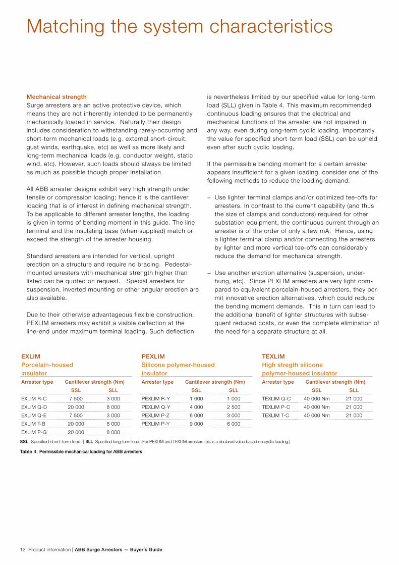
EXLIMPorcelain-housed insulator
PEXLIMSilicone polymer-housed insulator
TEXLIMHigh stregth silicone polymer-housed insulator
Arrester type Cantilever strength (Nm) Arrester type Cantilever strength (Nm) Arrester type Cantilever strength (Nm)
SSL SLL SSL SLL SSL SLL
EXLIM R-C 7 500 3 000 PEXLIM R-Y 1 600 1 000 TEXLIM Q-C 40 000 Nm 21 000
EXLIM Q-D 20 000 8 000 PEXLIM Q-Y 4 000 2 500 TEXLIM P-C 40 000 Nm 21 000
EXLIM Q-E 7 500 3 000 PEXLIM P-Z 6 000 3 000 TEXLIM T-C 40 000 Nm 21 000
EXLIM T-B 20 000 8 000 PEXLIM P-Y 9 000 6 000
EXLIM P-G 20 000 8 000
SSL Specified short-term load. | SLL Specified long-term load. (For PEXLIM and TEXLIM arresters this is a declared value based on cyclic loading.)
Table 4. Permissible mechanical loading for ABB arresters
Mechanical strengthSurge arresters are an active protective device, which means they are not inherently intended to be permanently mechanically loaded in service. Naturally their design includes consideration to withstanding rarely-occurring and short-term mechanical loads (e.g. external short-circuit, gust winds, earthquake, etc) as well as more likely and long-term mechanical loads (e.g. conductor weight, static wind, etc). However, such loads should always be limited as much as possible though proper installation.
All ABB arrester designs exhibit very high strength under tensile or compression loading; hence it is the cantilever loading that is of interest in defining mechanical strength. To be applicable to different arrester lengths, the loading is given in terms of bending moment in this guide. The line terminal and the insulating base (when supplied) match or exceed the strength of the arrester housing.
Standard arresters are intended for vertical, upright erection on a structure and require no bracing. Pedestal-mounted arresters with mechanical strength higher than listed can be quoted on request. Special arresters for suspension, inverted mounting or other angular erection are also available.
Due to their otherwise advantageous flexible construction, PEXLIM arresters may exhibit a visible deflection at the line-end under maximum terminal loading. Such deflection
is nevertheless limited by our specified value for long-term load (SLL) given in Table 4. This maximum recommended continuous loading ensures that the electrical and mechanical functions of the arrester are not impaired in any way, even during long-term cyclic loading. Importantly, the value for specified short-term load (SSL) can be upheld even after such cyclic loading.
If the permissible bending moment for a certain arrester appears insufficient for a given loading, consider one of the following methods to reduce the loading demand.
− Use lighter terminal clamps and/or optimized tee-offs for arresters. In contrast to the current capability (and thus the size of clamps and conductors) required for other substation equipment, the continuous current through an arrester is of the order of only a few mA. Hence, using a lighter terminal clamp and/or connecting the arresters by lighter and more vertical tee-offs can considerably reduce the demand for mechanical strength.
− Use another erection alternative (suspension, under-hung, etc). Since PEXLIM arresters are very light com-pared to equivalent porcelain-housed arresters, they per-mit innovative erection alternatives, which could reduce the bending moment demands. This in turn can lead to the additional benefit of lighter structures with subse-quent reduced costs, or even the complete elimination of the need for a separate structure at all.
Matching the system characteristics

ABB Surge Arresters — Buyer´s Guide | Product information 13
Neutral-ground arresters For neutral-ground arresters the recommended rated voltage is approximately the maximum system voltage divided by √3. The recommended neutral-ground arresters in the relevant sections are calculated for unearthed systems with relatively long fault duration. The electrical characteristics are identi-cal to standard catalogue arresters with the corresponding rated voltage. For such arresters, Uc is zero since they are not subject to any continuous voltage stress during normal service conditions. The neutral-ground arresters should pref-erably be of the same type as the phase-ground arresters. For resonant-earthed systems with long radial lines special considerations must be taken and a higher rated voltage (20% to 40%) than listed may be necessary.
Type designationThe type designation itself gives detailed information of the arrester and its application. See the figure below. As stan-dard, the arresters are meant for upright vertical erection. For under-hung erection, when desired, the type designation has the suffix letter ”H”. For other angular erection, please inform us at order. For non-standard arresters the type designation will have additional suffix letters, for example:
E Non-standard electrical data
M Non-standard mechanical data
P Non-standard metal-oxide columns
s
For line surge arresters, letter to be added here.
Y
Special applicationsPlease consult your nearest ABB representative for help in se-lection of arresters for special applications such as protection of shunt or series capacitor banks, cables and cable-aerial junctions, rotating machines, traction systems, overhead lines, HVDC or for non-standard arrester ratings or extreme me-chanical demands.
Ordering data for arrestersThe following information, at a minimum, is required with your order:
− Quantity and type designation − Rated voltage − Type of line terminal − Type of earth terminal − Type of surge counter, if any − Type of insulating base, if any.
(Insulating base is required if surge counter and/or leakage current measurements are desired. One base is required for each arrester.)
Ordering exampleBelow is a typical example of an order with three PEXLIM arresters and its accessories.
Number Item
3 PEXLIM Q192-YH245, rated voltage 192 kV
3 Line terminal type 1HSA 410 000-L
3 Earth terminal type 1HSA 420 000-A
3 Insulating base type 1HSA 430 000-A
3 Surge counter type EXCOUNT-C
Note! We recommend that the order form, on page 137, be filled-in and attached to your order to ensure inclusion of all the important parameters and commercial conditions.
Matching the system characteristics
14 Product information | ABB Surge Arresters — Buyer´s Guide
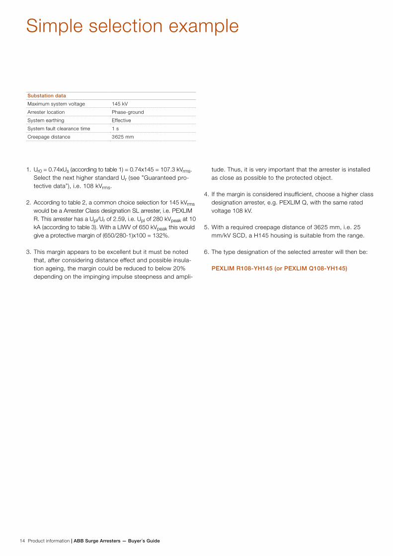
Simple selection example
Substation data
Maximum system voltage 145 kV
Arrester location Phase-ground
System earthing Effective
System fault clearance time 1 s
Creepage distance 3 625 mm
1. Ur0 = 0.74xUs (according to table 1) = 0.74x145 = 107.3 kVrms. Select the next higher standard Ur (see ”Guaranteed pro-tective data”), i.e. 108 kVrms.
2. According to table 2, a common choice selection for 145 kVrms would be a Arrester Class designation SL arrester, i.e. PEXLIM R. This arrester has a Upl/Ur of 2.59, i.e. Upl of 280 kVpeak at 10 kA (according to table 3). With a LIWV of 650 kVpeak this would give a protective margin of (650/280-1)x100 = 132%.
3. This margin appears to be excellent but it must be noted that, after considering distance effect and possible insula-tion ageing, the margin could be reduced to below 20% depending on the impinging impulse steepness and ampli-
tude. Thus, it is very important that the arrester is installed as close as possible to the protected object.
4. If the margin is considered insufficient, choose a higher class designation arrester, e.g. PEXLIM Q, with the same rated voltage 108 kV.
5. With a required creepage distance of 3625 mm, i.e. 25 mm/kV SCD, a H145 housing is suitable from the range.
6. The type designation of the selected arrester will then be: PEXLIM R108-YH145 (or PEXLIM Q108-YH145)
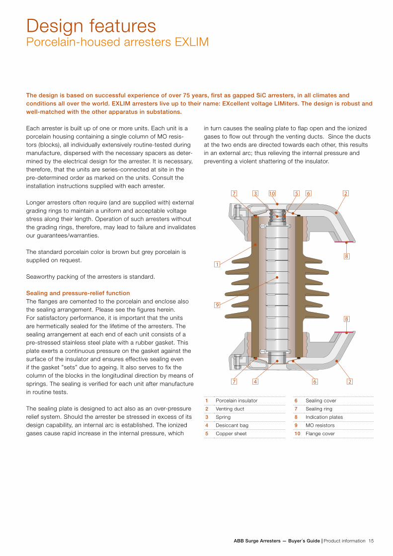
ABB Surge Arresters — Buyer´s Guide | Product information 15
Design featuresPorcelain-housed arresters EXLIM
Each arrester is built up of one or more units. Each unit is a porcelain housing containing a single column of MO resis-tors (blocks), all individually extensively routine-tested during manufacture, dispersed with the necessary spacers as deter-mined by the electrical design for the arrester. It is necessary, therefore, that the units are series-connected at site in the pre-determined order as marked on the units. Consult the installation instructions supplied with each arrester.
Longer arresters often require (and are supplied with) external grading rings to maintain a uniform and acceptable voltage stress along their length. Operation of such arresters without the grading rings, therefore, may lead to failure and invalidates our guarantees/warranties.
The standard porcelain color is brown but grey porcelain is supplied on request.
Seaworthy packing of the arresters is standard.
Sealing and pressure-relief functionThe flanges are cemented to the porcelain and enclose also the sealing arrangement. Please see the figures herein. For satisfactory performance, it is important that the units are hermetically sealed for the lifetime of the arresters. The sealing arrangement at each end of each unit consists of a pre-stressed stainless steel plate with a rubber gasket. This plate exerts a continuous pressure on the gasket against the surface of the insulator and ensures effective sealing even if the gasket ”sets” due to ageing. It also serves to fix the column of the blocks in the longitudinal direction by means of springs. The sealing is verified for each unit after manufacture in routine tests.
The sealing plate is designed to act also as an over-pressure relief system. Should the arrester be stressed in excess of its design capability, an internal arc is established. The ionized gases cause rapid increase in the internal pressure, which
The design is based on successful experience of over 75 years, first as gapped SiC arresters, in all climates and conditions all over the world. EXLIM arresters live up to their name: EXcellent voltage LIMiters. The design is robust and well-matched with the other apparatus in substations.
in turn causes the sealing plate to flap open and the ionized gases to flow out through the venting ducts. Since the ducts at the two ends are directed towards each other, this results in an external arc; thus relieving the internal pressure and preventing a violent shattering of the insulator.
1 Porcelain insulator 6 Sealing cover
2 Venting duct 7 Sealing ring
3 Spring 8 Indication plates
4 Desiccant bag 9 MO resistors
5 Copper sheet 10 Flange cover
7
1
9
3 10 5 6 2
7 4 6 2
8
8
16 Product information | ABB Surge Arresters — Buyer´s Guide
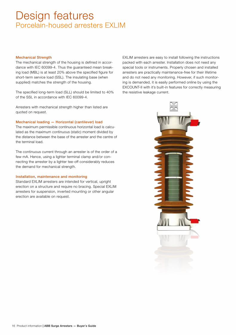
Mechanical StrengthThe mechanical strength of the housing is defined in accor-dance with IEC 60099-4. Thus the guaranteed mean break-ing load (MBL) is at least 20% above the specified figure for short-term service load (SSL). The insulating base (when supplied) matches the strength of the housing.
The specified long-term load (SLL) should be limited to 40% of the SSL in accordance with IEC 60099-4.
Arresters with mechanical strength higher than listed are quoted on request.
Mechanical loading — Horizontal (cantilever) loadThe maximum permissible continuous horizontal load is calcu-lated as the maximum continuous (static) moment divided by the distance between the base of the arrester and the centre of the terminal load.
The continuous current through an arrester is of the order of a few mA. Hence, using a lighter terminal clamp and/or con-necting the arrester by a lighter tee-off considerably reduces the demand for mechanical strength.
Installation, maintenance and monitoringStandard EXLIM arresters are intended for vertical, upright erection on a structure and require no bracing. Special EXLIM arresters for suspension, inverted mounting or other angular erection are available on request.
EXLIM arresters are easy to install following the instructions packed with each arrester. Installation does not need any special tools or instruments. Properly chosen and installed arresters are practically maintenance-free for their lifetime and do not need any monitoring. However, if such monitor-ing is demanded, it is easily performed online by using the EXCOUNT-II with it’s built-in features for correctly measuring the resistive leakage current.
Design featuresPorcelain-housed arresters EXLIM
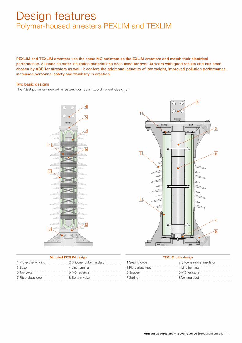
ABB Surge Arresters — Buyer´s Guide | Product information 17
Design featuresPolymer-housed arresters PEXLIM and TEXLIM
PEXLIM and TEXLIM arresters use the same MO resistors as the EXLIM arresters and match their electrical performance. Silicone as outer insulation material has been used for over 30 years with good results and has been chosen by ABB for arresters as well. It confers the additional benefits of low weight, improved pollution performance, increased personnel safety and flexibility in erection.
Two basic designsThe ABB polymer-housed arresters comes in two different designs:
5
4
7
1
2
3
6
8
6
7
8
5
4
1
2
3
TEXLIM tube design
1 Sealing cover 2 Silicone rubber insulator
3 Fibre glass tube 4 Line terminal
5 Spacers 6 MO resistors
7 Spring 8 Venting duct
Moulded PEXLIM design
1 Protective winding 2 Silicone rubber insulator
3 Base 4 Line terminal
5 Top yoke 6 MO resistors
7 Fibre glass loop 8 Bottom yoke
18 Product information | ABB Surge Arresters — Buyer´s Guide
Design featuresMoulded PEXLIM design
Design HighlightsEach arrester is built-up of one or more units, which in turn may be made up of one or more modules. Each module contains a single column of MO resistors (blocks), which are extensively individually routine-tested during manufacture, dispersed with the necessary spacers as determined by the electrical design for the arrester. The modules are standardized into different sizes based on electrical, mechanical and process consider-ations.
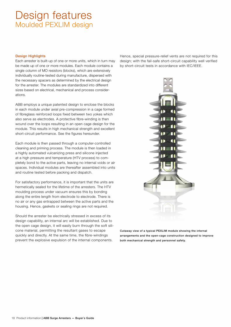
ABB employs a unique patented design to enclose the blocks in each module under axial pre-compression in a cage formed of fibreglass reinforced loops fixed between two yokes which also serve as electrodes. A protective fibre-winding is then wound over the loops resulting in an open cage design for the module. This results in high mechanical strength and excellent short-circuit performance. See the figures hereunder.
Each module is then passed through a computer-controlled cleaning and priming process. The module is then loaded in a highly automated vulcanizing press and silicone injected at a high pressure and temperature (HTV process) to com-pletely bond to the active parts, leaving no internal voids or air spaces. Individual modules are thereafter assembled into units and routine tested before packing and dispatch.
For satisfactory performance, it is important that the units are hermetically sealed for the lifetime of the arresters. The HTV moulding process under vacuum ensures this by bonding along the entire length from electrode to electrode. There is no air or any gas entrapped between the active parts and the housing. Hence, gaskets or sealing rings are not required.
Should the arrester be electrically stressed in excess of its design capability, an internal arc will be established. Due to the open cage design, it will easily burn through the soft sili-cone material, permitting the resultant gases to escape quickly and directly. At the same time, the fibre-windings prevent the explosive expulsion of the internal components.
Hence, special pressure-relief vents are not required for this design; with the fail-safe short-circuit capability well verified by short-circuit tests in accordance with IEC/IEEE.
Cutaway view of a typical PEXLIM module showing the internal
arrangements and the open-cage construction designed to improve
both mechanical strength and personnel safety.
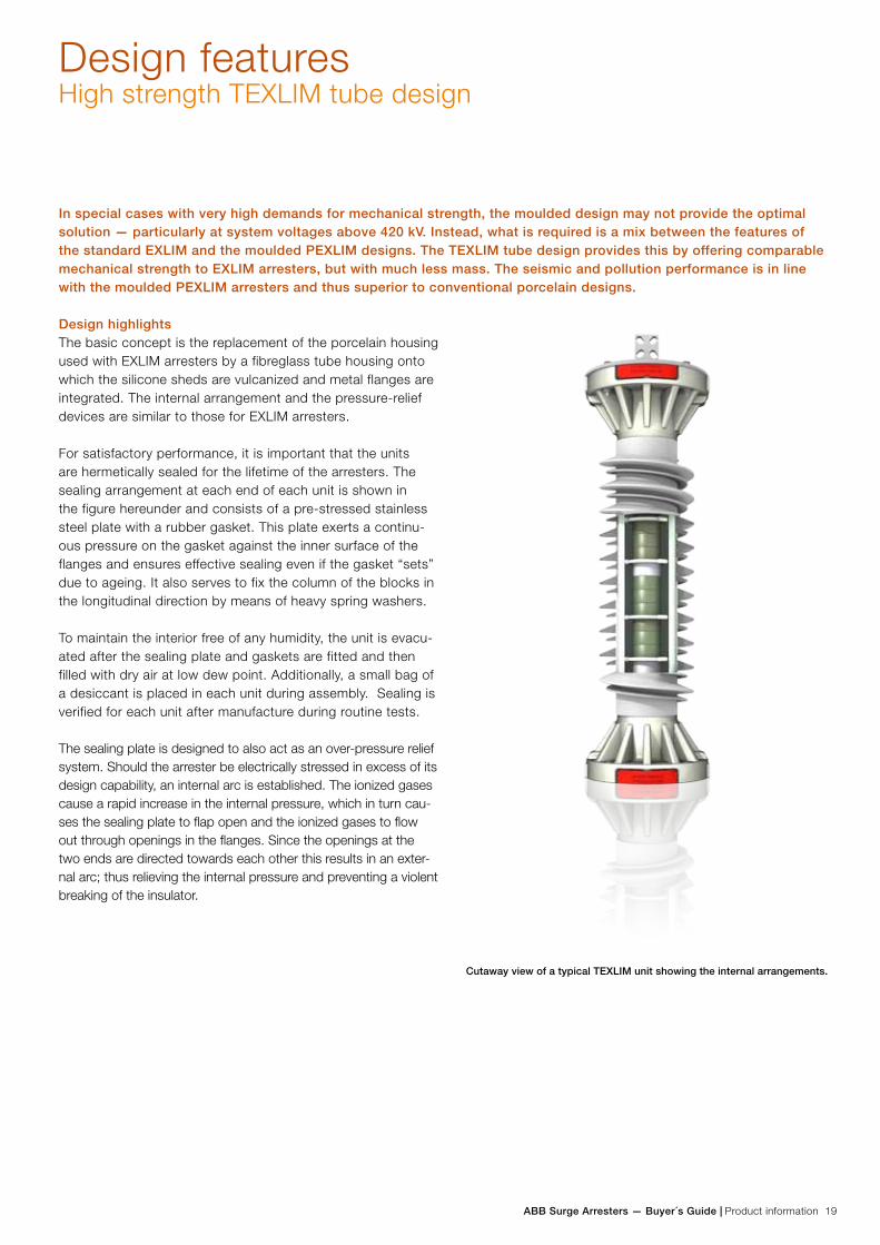
ABB Surge Arresters — Buyer´s Guide | Product information 19
Design featuresHigh strength TEXLIM tube design
Design highlightsThe basic concept is the replacement of the porcelain housing used with EXLIM arresters by a fibreglass tube housing onto which the silicone sheds are vulcanized and metal flanges are integrated. The internal arrangement and the pressure-relief devices are similar to those for EXLIM arresters.
For satisfactory performance, it is important that the units are hermetically sealed for the lifetime of the arresters. The sealing arrangement at each end of each unit is shown in the figure hereunder and consists of a pre-stressed stainless steel plate with a rubber gasket. This plate exerts a continu-ous pressure on the gasket against the inner surface of the flanges and ensures effective sealing even if the gasket “sets” due to ageing. It also serves to fix the column of the blocks in the longitudinal direction by means of heavy spring washers.
To maintain the interior free of any humidity, the unit is evacu-ated after the sealing plate and gaskets are fitted and then filled with dry air at low dew point. Additionally, a small bag of a desiccant is placed in each unit during assembly. Sealing is verified for each unit after manufacture during routine tests.
The sealing plate is designed to also act as an over-pressure relief system. Should the arrester be electrically stressed in excess of its design capability, an internal arc is established. The ionized gases cause a rapid increase in the internal pressure, which in turn cau-ses the sealing plate to flap open and the ionized gases to flow out through openings in the flanges. Since the openings at the two ends are directed towards each other this results in an exter-nal arc; thus relieving the internal pressure and preventing a violent breaking of the insulator.
Cutaway view of a typical TEXLIM unit showing the internal arrangements.
In special cases with very high demands for mechanical strength, the moulded design may not provide the optimal solution — particularly at system voltages above 420 kV. Instead, what is required is a mix between the features of the standard EXLIM and the moulded PEXLIM designs. The TEXLIM tube design provides this by offering comparable mechanical strength to EXLIM arresters, but with much less mass. The seismic and pollution performance is in line with the moulded PEXLIM arresters and thus superior to conventional porcelain designs.
20 Product information | ABB Surge Arresters — Buyer´s Guide
Silicone as an insulator
All PEXLIM and TEXLIM arresters utilize silicone for the external insulation. Silicone rubber is highly hydrophobic and resistant to UV radiation and has been shown to be the best insulation (compared to both porcelain and other polymers) based on world wide independent laboratory and field tests. ABB uses special fillers to enhance these properties as well as giving it high pollution resistance, tracking resistance and fire-extinguishing features. The silicone housing is available only in grey color. For additional information, please refer to publication 1HSM 9543 01-06en.
In a form-fit-function comparison, PEXLIM is the most optimized and cost-effective of the available polymer designs. A separately defining criteria often becomes the mechanical strength demands. TEXLIM would seemly have the advantage in this regard, and it could be that specific applications do require a very strong com-posite tube solution. However, mechanical loads should always be limited as much as possible though proper installation using good engineering practices, and by so doing, the PEXLIM design remains the first choice for the vast majority of applications.
ABB Surge Arresters — Buyer´s Guide | Product information 21
Installation, maintenance and monitoring
All ABB arresters are easy to install following the instructions packed with each arrester. Installation does not need any special tools or instruments.
The units of multiple-unit arresters must be series-con-nected at site in a pre-determined order as marked on the units and explained in the instructions that are packed in each case. An incorrect assembly may lead to failure and invalidates our warranty.
The design of tall arresters often requires external grading rings to maintain a uniform and acceptable voltage stress along their length. Such rings are included in the delivery of arresters. Installation or operation of such arresters without these grading rings may lead to failure and invalidates our warranty.
Properly chosen and installed arresters are practically mainte-nance-free for their lifetime and do not need any monitoring. However, if such monitoring is desired, it is easily performed online by using EXCOUNT-II with its built-in features for diag-nostic analysis of resistive leakage current. More information is available in the chapter dealing with accessories.
22 Product information | ABB Surge Arresters — Buyer´s Guide
Line surge arresters PEXLINKThe concept
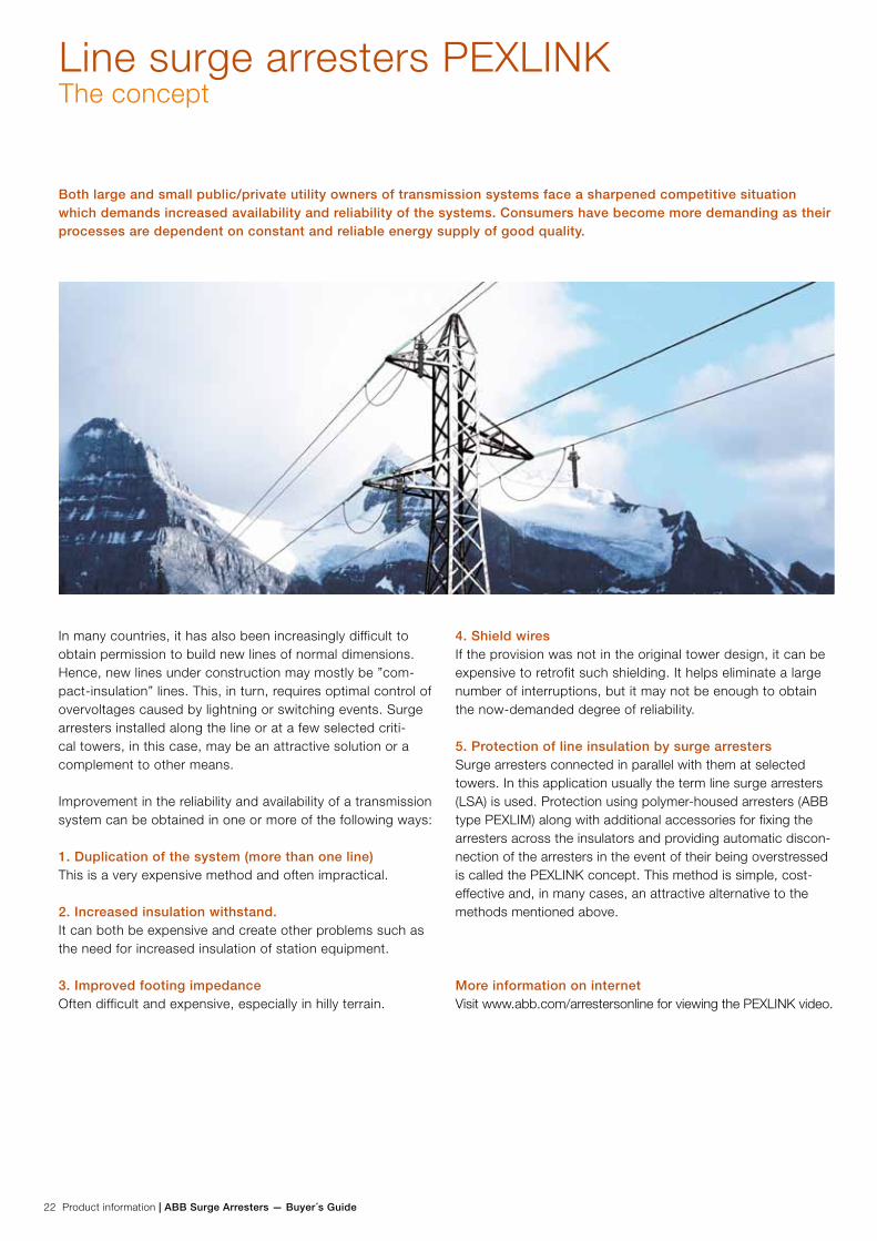
Both large and small public/private utility owners of transmission systems face a sharpened competitive situation which demands increased availability and reliability of the systems. Consumers have become more demanding as their processes are dependent on constant and reliable energy supply of good quality.
In many countries, it has also been increasingly difficult to obtain permission to build new lines of normal dimensions. Hence, new lines under construction may mostly be ”com-pact-insulation” lines. This, in turn, requires optimal control of overvoltages caused by lightning or switching events. Surge arresters installed along the line or at a few selected criti-cal towers, in this case, may be an attractive solution or a complement to other means.
Improvement in the reliability and availability of a transmission system can be obtained in one or more of the following ways:
1. Duplication of the system (more than one line)This is a very expensive method and often impractical.
2. Increased insulation withstand.It can both be expensive and create other problems such as the need for increased insulation of station equipment.
3. Improved footing impedanceOften difficult and expensive, especially in hilly terrain.
4. Shield wiresIf the provision was not in the original tower design, it can be expensive to retrofit such shielding. It helps eliminate a large number of interruptions, but it may not be enough to obtain the now-demanded degree of reliability.
5. Protection of line insulation by surge arresters Surge arresters connected in parallel with them at selected towers. In this application usually the term line surge arresters (LSA) is used. Protection using polymer-housed arresters (ABB type PEXLIM) along with additional accessories for fixing the arresters across the insulators and providing automatic discon-nection of the arresters in the event of their being overstressed is called the PEXLINK concept. This method is simple, cost-effective and, in many cases, an attractive alternative to the methods mentioned above.
More information on internetVisit www.abb.com/arrestersonline for viewing the PEXLINK video.
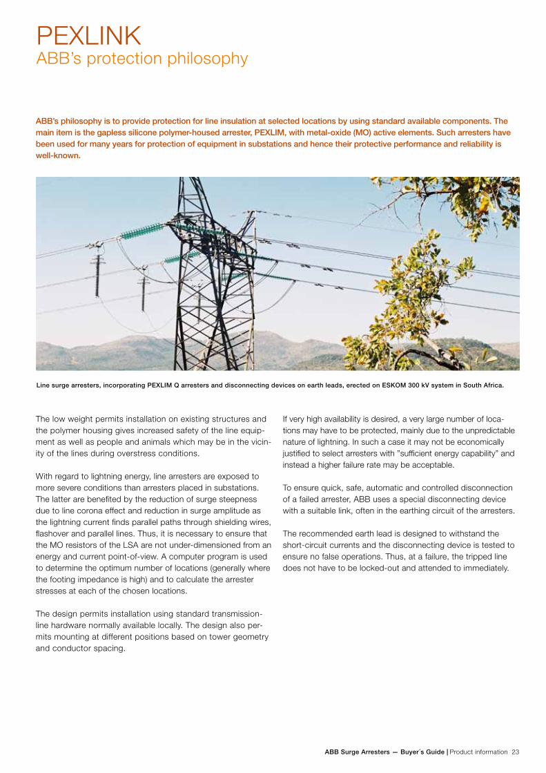
ABB Surge Arresters — Buyer´s Guide | Product information 23
PEXLINKABB’s protection philosophy
ABB’s philosophy is to provide protection for line insulation at selected locations by using standard available components. The main item is the gapless silicone polymer-housed arrester, PEXLIM, with metal-oxide (MO) active elements. Such arresters have been used for many years for protection of equipment in substations and hence their protective performance and reliability is well-known.
The low weight permits installation on existing structures and the polymer housing gives increased safety of the line equip-ment as well as people and animals which may be in the vicin-ity of the lines during overstress conditions.
With regard to lightning energy, line arresters are exposed to more severe conditions than arresters placed in substations. The latter are benefited by the reduction of surge steepness due to line corona effect and reduction in surge amplitude as the lightning current finds parallel paths through shielding wires, flashover and parallel lines. Thus, it is necessary to ensure that the MO resistors of the LSA are not under-dimensioned from an energy and current point-of-view. A computer program is used to determine the optimum number of locations (generally where the footing impedance is high) and to calculate the arrester stresses at each of the chosen locations.
The design permits installation using standard transmission-line hardware normally available locally. The design also per-mits mounting at different positions based on tower geometry and conductor spacing.
If very high availability is desired, a very large number of loca-tions may have to be protected, mainly due to the unpredictable nature of lightning. In such a case it may not be economically justified to select arresters with ”sufficient energy capability” and instead a higher failure rate may be acceptable.
To ensure quick, safe, automatic and controlled disconnection of a failed arrester, ABB uses a special disconnecting device with a suitable link, often in the earthing circuit of the arresters.
The recommended earth lead is designed to withstand the short-circuit currents and the disconnecting device is tested to ensure no false operations. Thus, at a failure, the tripped line does not have to be locked-out and attended to immediately.
Line surge arresters, incorporating PEXLIM Q arresters and disconnecting devices on earth leads, erected on ESKOM 300 kV system in South Africa.

24 Product information | ABB Surge Arresters — Buyer´s Guide
PEXLINKApplication
Increased line availabilityBy locating the PEXLINK on sections of lines with high footing im-pedance towers and one additional low footing-impedance tower at each end of the section, PEXLINK protects existing shielded and non-shielded lines from abnormal lightning surges (frequent or high amplitudes) and reduces the outages.
The reduced outages are beneficial also indirectly in that sensitive equipment is not damaged and the circuit breakers overhaul interval can be increased. Thus, total maintenance costs are also reduced.
This protection may be used for all system voltages where the stated abnormal conditions exist. Arresters with mod-erate energy capability are often sufficient. However, the high-current capability must be large and distribution-type arresters may not be suitable.
The diagram shows overvoltages phase-ground generated by three-phase reclosing of 550 kV, 200 km transmission line with a previous ground fault. For long EHV lines pre-insertion resistors traditionally are used to limit switching overvoltages. Surge arresters, as a robust and efficient alternative, could be located at line ends and along the line at selected points.
Switching overvoltage controlFor long EHV lines, surge arresters usually are located at line-ends. In addition, by locating arresters at one or more points along the line e.g. at midpoint or 1/3 and 2/3 line length switching surge overvoltages and thus line insulation require-ments could be limited without using preinsertion resistors. Arresters used for this type of application should be designed for high energy capability, especially at the receiving end of the line.
Compact-insulation linesArresters placed in parallel with line insulators permit a large degree of compacting of a transmission line with lower right-of-way costs as a result.
Line upgradingThe existing insulation level of a line, when suitably protected by arresters, may be upgraded for service at a higher system voltage leading to greater power transfer without much ad-ditional capital cost.
Extended station protectionBy locating arresters on towers near a substation, the risk of backflashovers near the station is eliminated. This results in reduction of steepness and amplitude of incoming travelling waves, thus improving the protection performance of station arresters and eliminating the need for additional expensive metal-enclosed arresters even for large GIS.
Substitute for shield wiresIn cases where provision of shield wires is not practical physi-cally or is very expensive, e.g. very long spans, very high tow-ers etc, arresters are a good and economical substitute.
Arresters located in all phases on each tower eliminate the need for both shield wires and good footing impedance and may be economically justified in cases where the cost of re-duction in footing impedance and the cost of overhead shield wire are very high.

ABB Surge Arresters — Buyer´s Guide | Product information 25
PEXLINKApplication
No arresters at all. Lightning stroke to tower number 5Very high risk for flashover due to high TFI (Tower Footing Impedance) with an earth fault followed by a circuit breaker operation as a consequence.
Arresters in all 9 towers. Lightning stroke to tower number 5The overvoltage profile is well below the LIWV of the system all along the section. An ideal protection is obtained.
1 2 3 4 5 6 7 8 9123456789
1011
Low TFI Low TFI High TFI High TFI High TFI High TFI Low TFILow TFIHigh TFI
Normal insulation strength (LIWV)
1 2 3 4 5 6 7 8 915
101520253035404550
Low TFI Low TFI High TFI High TFI High TFI High TFI Low TFILow TFIHigh TFI
Normal insulation strength (LIWV)
26 Product information | ABB Surge Arresters — Buyer´s Guide
PEXLINKFeatures
Lightning discharge capabilityIn general, arresters on lines are subjected to higher energy and current stresses caused by lightning than arresters in-stalled in stations. Furthermore, the associated waveform and durations differ considerably from those specified for station arrester applications. Thus, line arresters are defined in terms of their lightning discharge capability, and PEXLIM arresters perform well in this regard.
Arrester type Lightning discharge capability
as per IEC 60099-4 Annex H
Energy Charge
PEXLIM R 2.5 kJ/kV (Ur)* 1.0 As **
PEXLIM Q 4.0 kJ/kV (Ur)* 1.8 As **
PEXLIM P 7.0 kJ/kV (Ur)* 2.8 As **
* Ur = Rated voltage** As = Ampere second
A few examples can be seen in the figures for ”Some erection alternatives” on next page.
The disconnecting device is carefully chosen to perform its function only at the overload of the arrester.
The separation of the disconnector is quick and effective and the method of connection advised by ABB in each particular case ensures that neither the disconnected conductor nor the damaged arrester cause any interference with other live parts. Thus, after a failure, the line can be re-charged without attending to it immediately.
The disconnection is easily visible from the ground and thus locating it is simple for the maintenance crew.
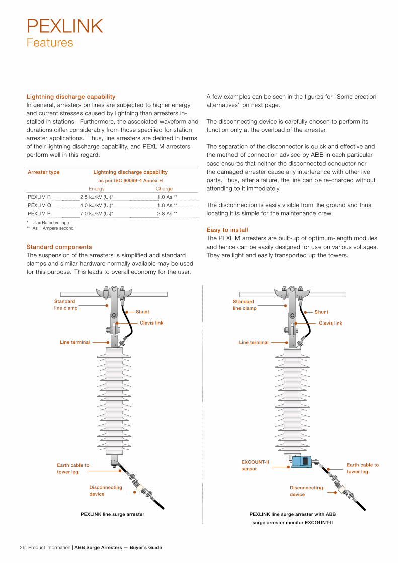
Easy to install The PEXLIM arresters are built-up of optimum-length modules and hence can be easily designed for use on various voltages. They are light and easily transported up the towers.
Disconnecting device
Disconnecting device
Earth cable to tower leg
Earth cable to tower leg
Standard line clamp
Standard line clamp
Shunt Shunt
Line terminal Line terminal
EXCOUNT-IIsensor
Clevis link Clevis link
PEXLINK line surge arrester PEXLINK line surge arrester with ABB
surge arrester monitor EXCOUNT-II
Standard componentsThe suspension of the arresters is simplified and standard clamps and similar hardware normally available may be used for this purpose. This leads to overall economy for the user.
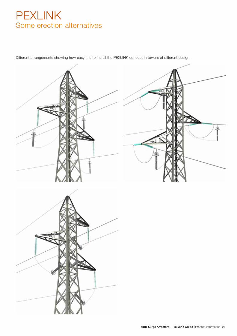
ABB Surge Arresters — Buyer´s Guide | Product information 27
PEXLINKSome erection alternatives
Different arrangements showing how easy it is to install the PEXLINK concept in towers of different design.
28 Product information | ABB Surge Arresters — Buyer´s Guide
Quality control and testing
ABB is certified to fulfil the requirements of ISO 9001
Type testsType (design) tests have been performed in accordance with IEC 60099-4. Test reports are available on request.
Routine testsRoutine tests are performed on MO resistors as well as on as-sembled arrester units and accessories. The most important type tests data is verified on all batches of MO resistors, thus verifying catalogue data.
Tests on MO resistorsEnergy withstand test on all blocksEach individual MO resistor passes three energy test cycles with cooling in-between. In each cycle, the injected energy is in excess of the rated energy capability. Blocks with in-sufficient energy capability are automatically rejected.
Classification and inspectionEach individual MO resistor is classified at 1 mA (d.c.) and 10 kA (8/20 µs) and the voltages are printed on each block together with a batch identification. Finally all blocks are visually inspected.
Accelerated life test on samplesPower losses after 1 000 hours calculated from a test with shorter duration (approximately 300 hours) at an elevated temperature of 115 °C at 1.05 times Uc shall not exceed the losses at start of the test. Batches in which unapproved blocks appear are rejected.
Energy capability test on samplesValidation of repetitive charge transfer rating (Qrs), based on the same sampling and test procedure and criteria as the IEC 60099-4 type test for station class. The samples are repre-sentative of the highest residual voltage of MO resistors from the individual batch in order to verify the statistical quality of each produced batch of all sizes of MO resistors. Batches which do not fulfill the criteria are rejected.
Impulse current test on samplesSelected blocks are subjected to two 100kA current impulses (4/10 µs) at spaced intervals.
Other sample testsIn addition to the above, low current characteristics, pro-tection characteristics, power losses and capacitance are checked to verify the inherent MO resistor parameters.
Tests on assembled mechanical unitsRoutine tests on units fulfil the demands of both IEC 60099-4 and ANSI/IEEE C62.11. Each arrester has a unique serial number.
Guaranteed residual voltageThe residual voltage at 10 kA, 8/20 µs impulse current of each unit is calculated as the sum of the residual voltages for all blocks connected in series in the unit.
The residual voltage of the complete arrester is the sum of the residual voltages for its units.
Tightness check (only for EXLIM and TEXLIM arresters)During manufacture, a vacuum is drawn on the internal volume and then dry air is pumped in, together with a small amount of helium tracer gas, before sealing off the unit. A leakage test is performed by placing each unit in a vacuum chamber connected to a He-spectrometer. Maximum permis-sible leakage rate of Helium is 0.0001 mbarl/s at a pressure difference of 0.1 MPa as a pass/ no pass test.
Power frequency reference voltage Reference voltage is measured on each arrester unit.
Internal coronaThe satisfactory absence of partial discharge is checked on each unit at 0.9 times Ur. A steady internal corona level of not greater than 10 pC is required in a pass/no-pass test.
Grading currentThe total leakage current passing through the arrester unit is measured at Uc for information only.
Power lossesPower loss is measured at Uc on each unit verifying that the thermal performance is in compliance with performed type tests.
Test reportsRoutine test reports are filed and are available on request.
Tests on accessories
Surge counters and monitorsAll such devices are routinely function-tested before leaving the factory.
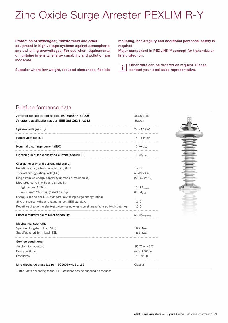
ABB Surge Arresters — Buyer´s Guide | Technical information 29
Zinc Oxide Surge Arrester PEXLIM R-Y
Protection of switchgear, transformers and other equipment in high voltage systems against atmospheric and switching overvoltages. For use when requirements of lightning intensity, energy capability and pollution are moderate.
Superior where low weight, reduced clearances, flexible
Brief performance dataArrester classification as per IEC 60099-4 Ed 3.0
Arrester classification as per IEEE Std C62.11-2012
Station; SL
Station
System voltages (Us) 24 - 170 kV
Rated voltages (Ur) 18 - 144 kV
Nominal discharge current (IEC) 10 kApeak
Lightning impulse classifying current (ANSI/IEEE) 10 kApeak
Charge, energy and current withstand:
Repetitive charge transfer rating, Qrs (IEC)
Thermal energy rating, Wth (IEC)
Single impulse energy capability (2 ms to 4 ms impulse)
Discharge current withstand strength:
High current 4/10 µs
Low current 2 000 µs, (based on Qrs)
Energy class as per IEEE standard (switching surge energy rating)
Single-impulse withstand rating as per IEEE standard
Repetitive charge transfer test value - sample tests on all manufactured block batches
1.2 C
5 kJ/kV (Ur)
2.5 kJ/kV (Ur)
100 kApeak
600 Apeak
-
1.2 C
1.5 C
Short-circuit/Pressure relief capability 50 kArms(sym)
Mechanical strength:
Specified long-term load (SLL)Specified short-term load (SSL)
1 000 Nm
1 600 Nm
Service conditions:
Ambient temperature
Design altitude
Frequency
-50 °C to +45 °C
max. 1 000 m
15 - 62 Hz
Line discharge class (as per IEC60099-4, Ed. 2.2 Class 2
Further data according to the IEEE standard can be supplied on request
mounting, non-fragility and additional personnel safety is required.Major component in PEXLINKTM concept for transmission line protection.
Other data can be ordered on request. Please contact your local sales representative.
30 Technical information | ABB Surge Arresters — Buyer´s Guide
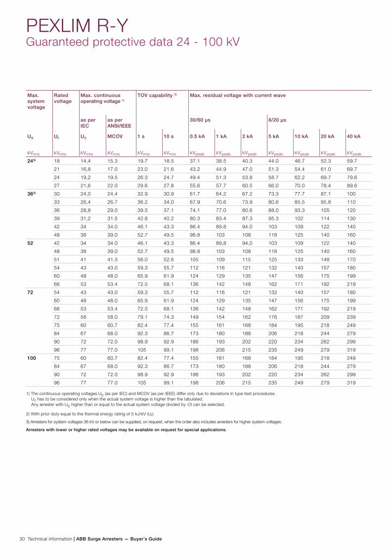
PEXLIM R-YGuaranteed protective data 24 - 100 kV
Max. system voltage
Rated voltage
Max. continuous operating voltage 1)
TOV capability 2) Max. residual voltage with current wave
as per IEC
as per ANSI/IEEE
30/60 µs 8/20 µs
Us
kVrms
Ur
kVrms
Uc
kVrms
MCOV
kVrms
1 s
kVrms
10 s
kVrms
0.5 kA
kVpeak
1 kA
kVpeak
2 kA
kVpeak
5 kA
kVpeak
10 kA
kVpeak
20 kA
kVpeak
40 kA
kVpeak
243) 18 14,4 15.3 19.7 18.5 37.1 38.5 40.3 44.0 46.7 52.3 59.7
21 16,8 17.0 23.0 21.6 43.2 44.9 47.0 51.3 54.4 61.0 69.7
24 19,2 19.5 26.3 24.7 49.4 51.3 53.8 58.7 62.2 69.7 79.6
27 21,6 22.0 29.6 27.8 55.6 57.7 60.5 66.0 70.0 78.4 89.6
363) 30 24,0 24.4 32.9 30.9 61.7 64.2 67.2 73.3 77.7 87.1 100
33 26,4 26.7 36.2 34.0 67.9 70.6 73.9 80.6 85.5 95.8 110
36 28,8 29.0 39.5 37.1 74.1 77.0 80.6 88.0 93.3 105 120
39 31,2 31.5 42.8 40.2 80.3 83.4 87.3 95.3 102 114 130
42 34 34.0 46.1 43.3 86.4 89.8 94.0 103 109 122 140
48 38 39.0 52.7 49.5 98.8 103 108 118 125 140 160
52 42 34 34.0 46.1 43.3 86.4 89,8 94,0 103 109 122 140
48 38 39.0 52.7 49.5 98.8 103 108 118 125 140 160
51 41 41.3 56.0 52.6 105 109 115 125 133 148 170
54 43 43.0 59.3 55.7 112 116 121 132 140 157 180
60 48 48.0 65.9 61.9 124 129 135 147 156 175 199
66 53 53.4 72.5 68.1 136 142 148 162 171 192 219
72 54 43 43.0 59.3 55.7 112 116 121 132 140 157 180
60 48 48.0 65.9 61.9 124 129 135 147 156 175 199
66 53 53.4 72.5 68.1 136 142 148 162 171 192 219
72 58 58.0 79.1 74.3 149 154 162 176 187 209 239
75 60 60.7 82.4 77.4 155 161 168 184 195 218 249
84 67 68.0 92.3 86.7 173 180 188 206 218 244 279
90 72 72.0 98.9 92.9 186 193 202 220 234 262 299
96 77 77.0 105 99.1 198 206 215 235 249 279 319
100 75 60 60.7 82.4 77.4 155 161 168 184 195 218 249
84 67 68.0 92.3 86.7 173 180 188 206 218 244 279
90 72 72.0 98.9 92.9 186 193 202 220 234 262 299
96 77 77.0 105 99.1 198 206 215 235 249 279 319
1) The continuous operating voltages Uc (as per IEC) and MCOV (as per IEEE) differ only due to deviations in type test procedures. Uc has to be considered only when the actual system voltage is higher than the tabulated. Any arrester with Uc higher than or equal to the actual system voltage divided by √3 can be selected.
2) With prior duty equal to the thermal energy rating of 5 kJ/kV (Ur)
3) Arresters for system voltages 36 kV or below can be supplied, on request, when the order also includes arresters for higher system voltages.
Arresters with lower or higher rated voltages may be available on request for special applications.
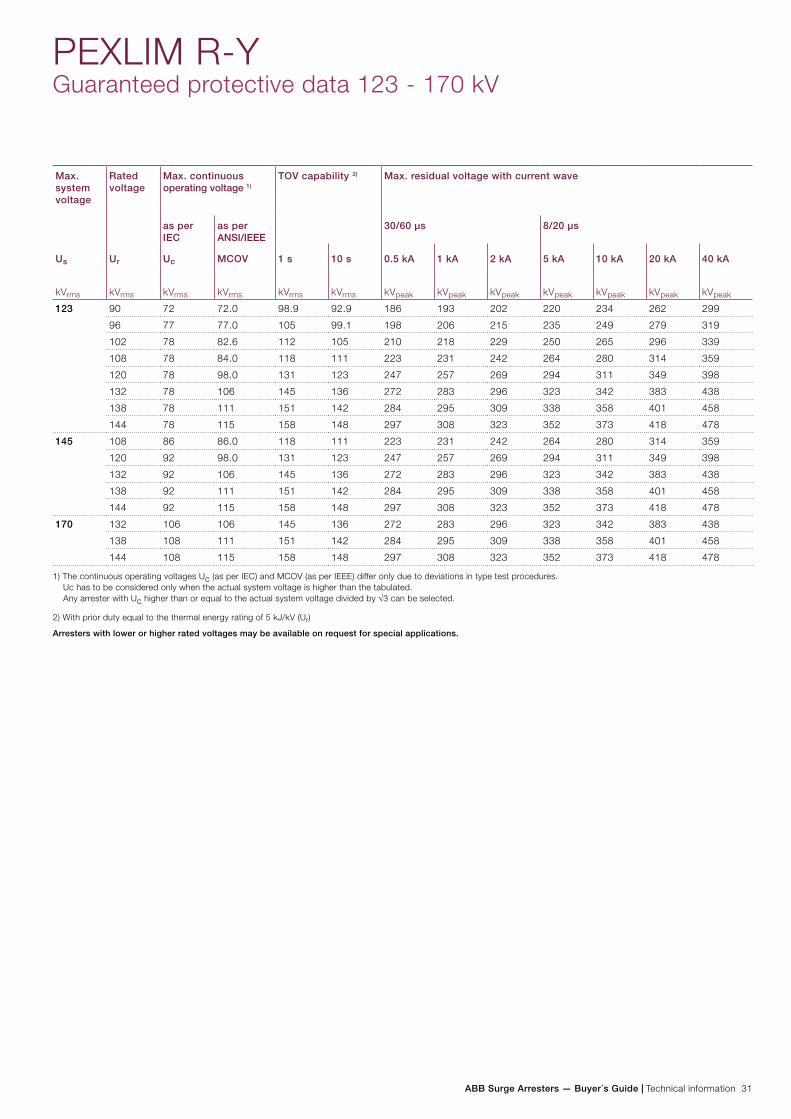
ABB Surge Arresters — Buyer´s Guide | Technical information 31
Max. system voltage
Rated voltage
Max. continuous operating voltage 1)
TOV capability 2) Max. residual voltage with current wave
as per IEC
as per ANSI/IEEE
30/60 µs 8/20 µs
Us
kVrms
Ur
kVrms
Uc
kVrms
MCOV
kVrms
1 s
kVrms
10 s
kVrms
0.5 kA
kVpeak
1 kA
kVpeak
2 kA
kVpeak
5 kA
kVpeak
10 kA
kVpeak
20 kA
kVpeak
40 kA
kVpeak
123 90 72 72.0 98.9 92.9 186 193 202 220 234 262 299
96 77 77.0 105 99.1 198 206 215 235 249 279 319
102 78 82.6 112 105 210 218 229 250 265 296 339
108 78 84.0 118 111 223 231 242 264 280 314 359
120 78 98.0 131 123 247 257 269 294 311 349 398
132 78 106 145 136 272 283 296 323 342 383 438
138 78 111 151 142 284 295 309 338 358 401 458
144 78 115 158 148 297 308 323 352 373 418 478
145 108 86 86.0 118 111 223 231 242 264 280 314 359
120 92 98.0 131 123 247 257 269 294 311 349 398
132 92 106 145 136 272 283 296 323 342 383 438
138 92 111 151 142 284 295 309 338 358 401 458
144 92 115 158 148 297 308 323 352 373 418 478
170 132 106 106 145 136 272 283 296 323 342 383 438
138 108 111 151 142 284 295 309 338 358 401 458
144 108 115 158 148 297 308 323 352 373 418 478
1) The continuous operating voltages Uc (as per IEC) and MCOV (as per IEEE) differ only due to deviations in type test procedures. Uc has to be considered only when the actual system voltage is higher than the tabulated. Any arrester with Uc higher than or equal to the actual system voltage divided by √3 can be selected.
2) With prior duty equal to the thermal energy rating of 5 kJ/kV (Ur)
Arresters with lower or higher rated voltages may be available on request for special applications.
PEXLIM R-YGuaranteed protective data 123 - 170 kV
32 Technical information | ABB Surge Arresters — Buyer´s Guide
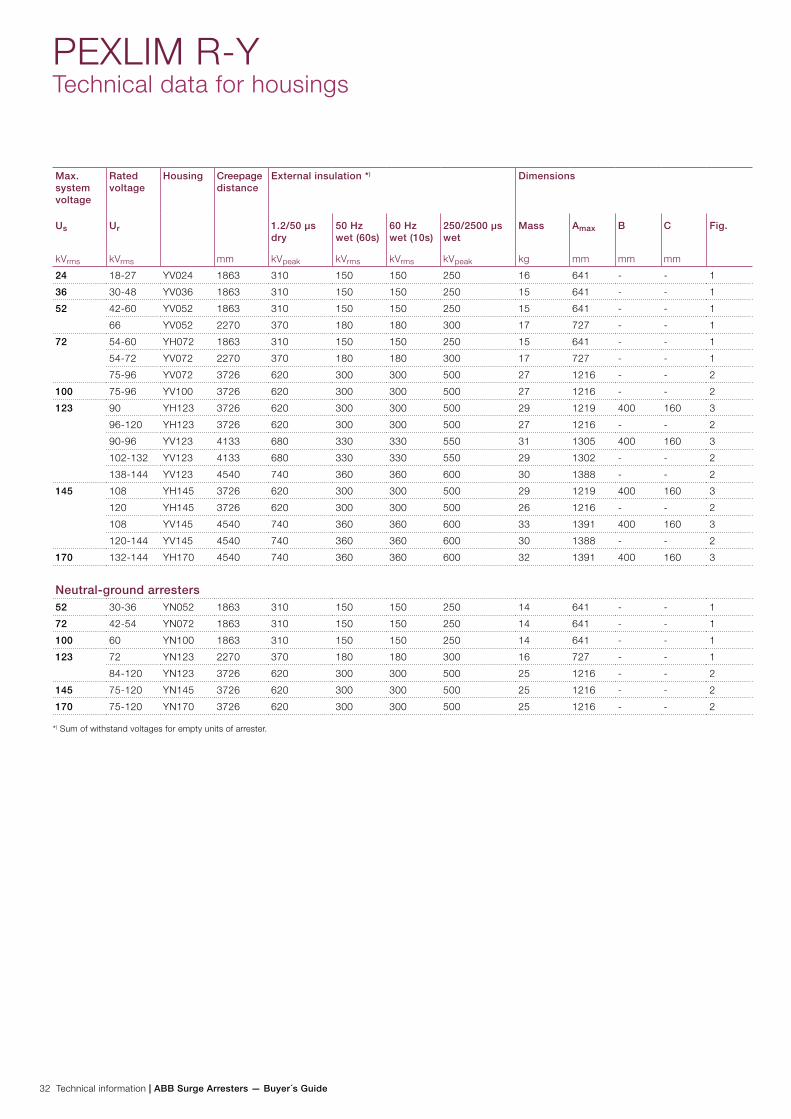
PEXLIM R-YTechnical data for housings
Max. system voltage
Rated voltage
Housing Creepage distance
mm
External insulation *) Dimensions
Us
kVrms
Ur
kVrms
1.2/50 µs dry
kVpeak
50 Hz wet (60s)
kVrms
60 Hz wet (10s)
kVrms
250/2500 µs wet
kVpeak
Mass
kg
Amax
mm
B
mm
C
mm
Fig.
24 18-27 YV024 1863 310 150 150 250 16 641 - - 1
36 30-48 YV036 1863 310 150 150 250 15 641 - - 1
52 42-60 YV052 1863 310 150 150 250 15 641 - - 1
66 YV052 2270 370 180 180 300 17 727 - - 1
72 54-60 YH072 1863 310 150 150 250 15 641 - - 1
54-72 YV072 2270 370 180 180 300 17 727 - - 1
75-96 YV072 3726 620 300 300 500 27 1216 - - 2
100 75-96 YV100 3726 620 300 300 500 27 1216 - - 2
123 90 YH123 3726 620 300 300 500 29 1219 400 160 3
96-120 YH123 3726 620 300 300 500 27 1216 - - 2
90-96 YV123 4133 680 330 330 550 31 1305 400 160 3
102-132 YV123 4133 680 330 330 550 29 1302 - - 2
138-144 YV123 4540 740 360 360 600 30 1388 - - 2
145 108 YH145 3726 620 300 300 500 29 1219 400 160 3
120 YH145 3726 620 300 300 500 26 1216 - - 2
108 YV145 4540 740 360 360 600 33 1391 400 160 3
120-144 YV145 4540 740 360 360 600 30 1388 - - 2
170 132-144 YH170 4540 740 360 360 600 32 1391 400 160 3
Neutral-ground arresters52 30-36 YN052 1863 310 150 150 250 14 641 - - 1
72 42-54 YN072 1863 310 150 150 250 14 641 - - 1
100 60 YN100 1863 310 150 150 250 14 641 - - 1
123 72 YN123 2270 370 180 180 300 16 727 - - 1
84-120 YN123 3726 620 300 300 500 25 1216 - - 2
145 75-120 YN145 3726 620 300 300 500 25 1216 - - 2
170 75-120 YN170 3726 620 300 300 500 25 1216 - - 2
*) Sum of withstand voltages for empty units of arrester.
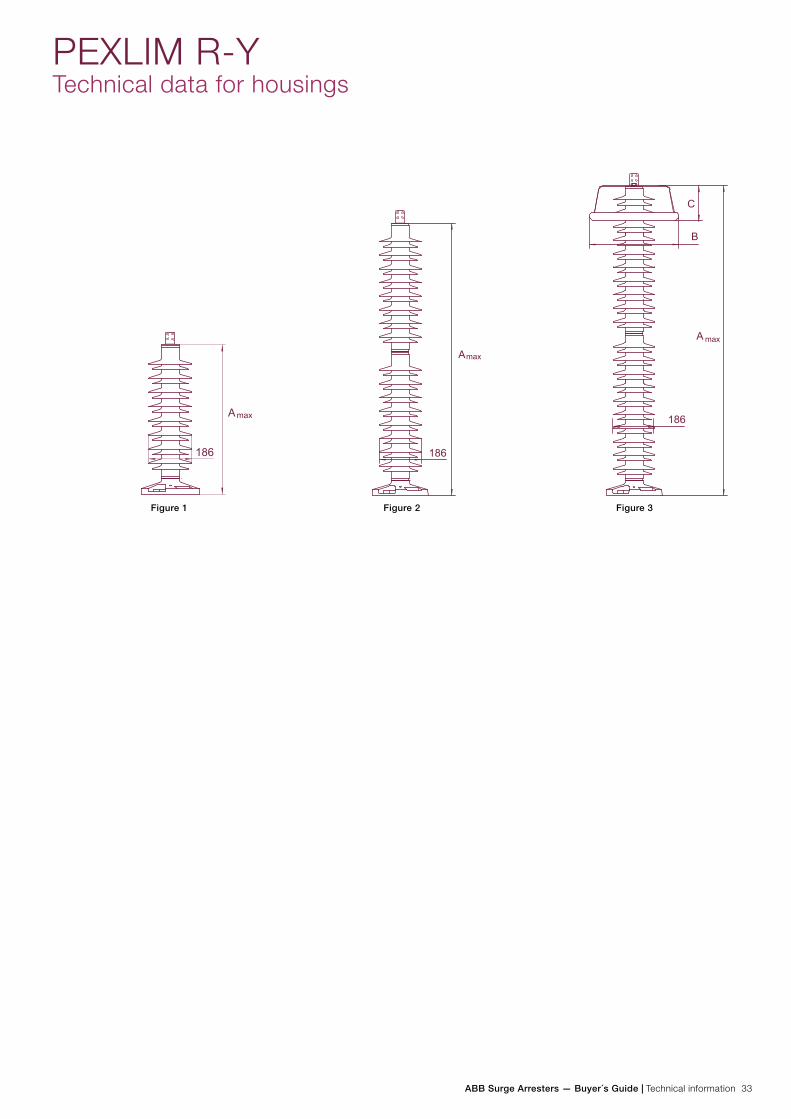
ABB Surge Arresters — Buyer´s Guide | Technical information 33
PEXLIM R-YTechnical data for housings
Figure 1 Figure 2 Figure 3

34 Technical information | ABB Surge Arresters — Buyer´s Guide
Line terminals
1HSA410 000-L
Aluminium
1HSA410 000-M
Aluminium flag with other
items in stainless steel
1HSA410 000-N
Aluminium
1HSA410 000-P
Stainless steel
Earth terminals
1HSA420 000-A
Stainless steel
1HSA420 000-B
Stainless steel
Drilling plans
Without insulating base
Aluminium
Insulating base
1HSA430 000-H
Epoxy resin
M12 bolts for connection to structure
are not supplied by ABB. Required
threaded grip length is 15-20 mm.
PEXLIM R-YAccessories
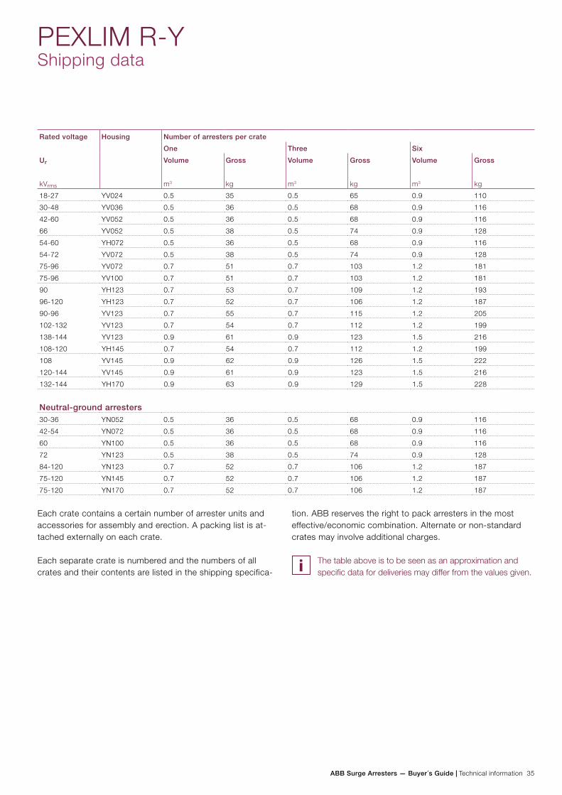
ABB Surge Arresters — Buyer´s Guide | Technical information 35
Rated voltage Housing Number of arresters per crate
One Three Six
Ur
kVrms
Volume
m3
Gross
kg
Volume
m3
Gross
kg
Volume
m3
Gross
kg
18-27 YV024 0.5 35 0.5 65 0.9 110
30-48 YV036 0.5 36 0.5 68 0.9 116
42-60 YV052 0.5 36 0.5 68 0.9 116
66 YV052 0.5 38 0.5 74 0.9 128
54-60 YH072 0.5 36 0.5 68 0.9 116
54-72 YV072 0.5 38 0.5 74 0.9 128
75-96 YV072 0.7 51 0.7 103 1.2 181
75-96 YV100 0.7 51 0.7 103 1.2 181
90 YH123 0.7 53 0.7 109 1.2 193
96-120 YH123 0.7 52 0.7 106 1.2 187
90-96 YV123 0.7 55 0.7 115 1.2 205
102-132 YV123 0.7 54 0.7 112 1.2 199
138-144 YV123 0.9 61 0.9 123 1.5 216
108-120 YH145 0.7 54 0.7 112 1.2 199
108 YV145 0.9 62 0.9 126 1.5 222
120-144 YV145 0.9 61 0.9 123 1.5 216
132-144 YH170 0.9 63 0.9 129 1.5 228
Neutral-ground arresters30-36 YN052 0.5 36 0.5 68 0.9 116
42-54 YN072 0.5 36 0.5 68 0.9 116
60 YN100 0.5 36 0.5 68 0.9 116
72 YN123 0.5 38 0.5 74 0.9 128
84-120 YN123 0.7 52 0.7 106 1.2 187
75-120 YN145 0.7 52 0.7 106 1.2 187
75-120 YN170 0.7 52 0.7 106 1.2 187
PEXLIM R-YShipping data
Each crate contains a certain number of arrester units and accessories for assembly and erection. A packing list is at-tached externally on each crate.
Each separate crate is numbered and the numbers of all crates and their contents are listed in the shipping specifica-
tion. ABB reserves the right to pack arresters in the most effective/economic combination. Alternate or non-standard crates may involve additional charges.
The table above is to be seen as an approximation and specific data for deliveries may differ from the values given.
36 Technical information | ABB Surge Arresters — Buyer´s Guide
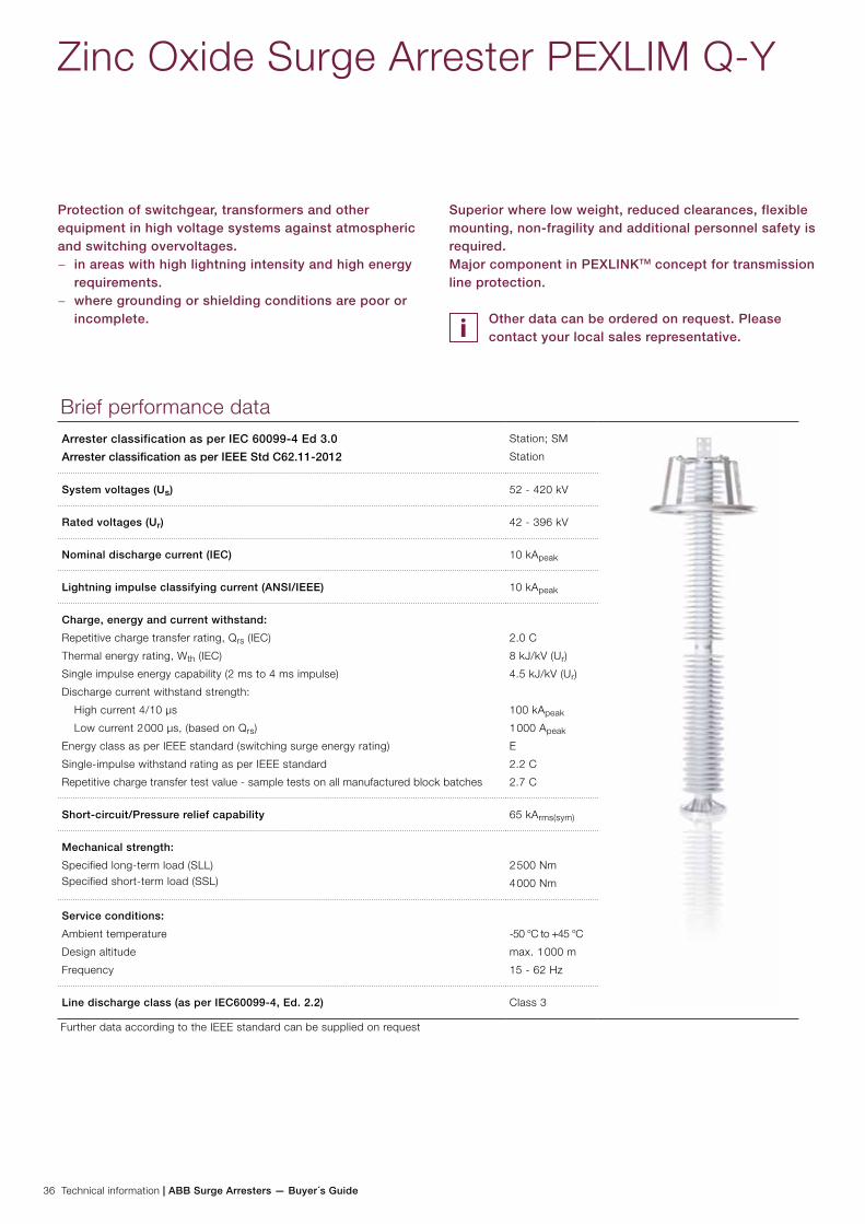
Zinc Oxide Surge Arrester PEXLIM Q-Y
Protection of switchgear, transformers and other equipment in high voltage systems against atmospheric and switching overvoltages.
− in areas with high lightning intensity and high energy requirements.
− where grounding or shielding conditions are poor or incomplete.
Superior where low weight, reduced clearances, flexible mounting, non-fragility and additional personnel safety is required.Major component in PEXLINKTM concept for transmission line protection.
Other data can be ordered on request. Please contact your local sales representative.
Brief performance dataArrester classification as per IEC 60099-4 Ed 3.0
Arrester classification as per IEEE Std C62.11-2012
Station; SM
Station
System voltages (Us) 52 - 420 kV
Rated voltages (Ur) 42 - 396 kV
Nominal discharge current (IEC) 10 kApeak
Lightning impulse classifying current (ANSI/IEEE) 10 kApeak
Charge, energy and current withstand:
Repetitive charge transfer rating, Qrs (IEC)
Thermal energy rating, Wth (IEC)
Single impulse energy capability (2 ms to 4 ms impulse)
Discharge current withstand strength:
High current 4/10 µs
Low current 2 000 µs, (based on Qrs)
Energy class as per IEEE standard (switching surge energy rating)
Single-impulse withstand rating as per IEEE standard
Repetitive charge transfer test value - sample tests on all manufactured block batches
2.0 C
8 kJ/kV (Ur)
4.5 kJ/kV (Ur)
100 kApeak
1 000 Apeak
E
2.2 C
2.7 C
Short-circuit/Pressure relief capability 65 kArms(sym)
Mechanical strength:
Specified long-term load (SLL)Specified short-term load (SSL)
2 500 Nm
4 000 Nm
Service conditions:
Ambient temperature
Design altitude
Frequency
-50 °C to +45 °C
max. 1 000 m
15 - 62 Hz
Line discharge class (as per IEC60099-4, Ed. 2.2) Class 3
Further data according to the IEEE standard can be supplied on request
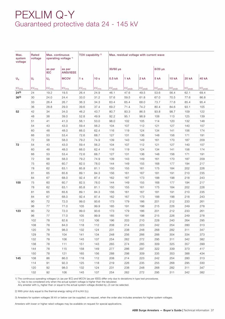
ABB Surge Arresters — Buyer´s Guide | Technical information 37
PEXLIM Q-YGuaranteed protective data 24 - 145 kV
Max. system voltage
Rated voltage
Max. continuous operating voltage 1)
TOV capability 2) Max. residual voltage with current wave
as per IEC
as per ANSI/IEEE
30/60 µs 8/20 µs
Us
kVrms
Ur
kVrms
Uc
kVrms
MCOV
kVrms
1 s
kVrms
10 s
kVrms
0.5 kA
kVpeak
1 kA
kVpeak
2 kA
kVpeak
5 kA
kVpeak
10 kA
kVpeak
20 kA
kVpeak
40 kA
kVpeak
243) 24 19.2 19.5 26.4 24.9 46.1 47.6 49.5 53.6 56.4 62.1 69.4
363) 30 24.0 24.4 33.0 31.2 57.6 59.5 61.8 67.0 70.5 77.6 86.8
33 26.4 26.7 36.3 34.3 63.4 65.4 68.0 73.7 77.6 85.4 95.4
36 28.8 29.0 39.6 37.4 69.2 71.4 74.2 80.4 84.6 93.1 105
52 42 34 34.0 46.2 43.7 80.7 83.3 86.5 93.8 98.7 109 122
48 38 39.0 52.8 49.9 92.2 95.1 98.9 108 113 125 139
51 41 41.3 56.1 53.0 98.0 102 105 114 120 132 148
54 43 43.0 59.4 56.2 104 107 112 121 127 140 157
60 48 48.0 66.0 62.4 116 119 124 134 141 156 174
66 53 53.4 72.6 68.7 127 131 136 148 156 171 191
72 58 58.0 79.2 74.9 139 143 149 161 170 187 209
72 54 43 43.0 59.4 56.2 104 107 112 121 127 140 157
60 48 48.0 66.0 62.4 116 119 124 134 141 156 174
66 53 53.4 72.6 68.7 127 131 136 148 156 171 191
72 58 58.0 79.2 74.9 139 143 149 161 170 187 209
75 60 60.7 82.5 78.0 144 149 155 168 177 194 217
78 62 63.1 85.8 81.1 150 155 161 175 184 202 226
81 65 65.6 89.1 84.3 156 161 167 181 191 210 235
84 67 68.0 92.4 87.4 162 167 173 188 198 218 243
100 75 60 60.7 82.5 78.0 144 149 155 168 177 194 217
78 62 63.1 85.8 81.1 150 155 161 175 184 202 226
81 65 65.6 89.1 84.3 156 161 167 181 191 210 235
84 67 68.0 92.4 87.4 162 167 173 188 198 218 243
90 72 72.0 99.0 93.6 173 179 186 201 212 233 261
96 77 77.0 105 99.9 185 191 198 215 226 249 278
123 90 72 72.0 99.0 93.6 173 179 186 201 212 233 261
96 77 77.0 105 99.9 185 191 198 215 226 249 278
102 78 82.6 112 106 196 203 210 228 240 264 295
108 78 84.0 118 112 208 214 223 242 254 280 313
120 78 98.0 132 124 231 238 248 268 282 311 347
129 78 104 141 134 248 256 266 288 304 334 373
132 78 106 145 137 254 262 272 295 311 342 382
138 78 111 151 143 265 274 285 309 325 357 399
144 78 115 158 149 277 286 297 322 339 373 417
150 78 121 165 156 288 298 309 335 353 388 434
145 108 86 86.0 118 112 208 214 223 242 254 280 313
114 91 92.3 125 118 219 226 235 255 268 295 330
120 92 98.0 132 124 231 238 248 268 282 311 347
132 92 106 145 137 254 262 272 295 311 342 382
1) The continuous operating voltages Uc (as per IEC) and MCOV (as per IEEE) differ only due to deviations in type test procedures. Uc has to be considered only when the actual system voltage is higher than the tabulated. Any arrester with Uc higher than or equal to the actual system voltage divided by √3 can be selected.
2) With prior duty equal to the thermal energy rating of 8 kJ/kV (Ur).
3) Arresters for system voltages 36 kV or below can be supplied, on request, when the order also includes arresters for higher system voltages.
Arresters with lower or higher rated voltages may be available on request for special applications.
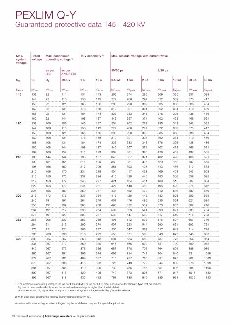
38 Technical information | ABB Surge Arresters — Buyer´s Guide
PEXLIM Q-YGuaranteed protective data 145 - 420 kV
Max. system voltage
Rated voltage
Max. continuous operating voltage 1)
TOV capability 2) Max. residual voltage with current wave
as per IEC
as per ANSI/IEEE
30/60 µs 8/20 µs
Um
kVrms
Ur
kVrms
Uc
kVrms
MCOV
kVrms
1 s
kVrms
10 s
kVrms
0.5 kA
kVpeak
1 kA
kVpeak
2 kA
kVpeak
5 kA
kVpeak
10 kA
kVpeak
20 kA
kVpeak
40 kA
kVpeak
145 138 92 111 151 143 265 274 285 309 325 357 399
144 92 115 158 149 277 286 297 322 339 373 417
150 92 121 165 156 288 298 309 335 353 388 434
162 92 131 178 168 312 321 334 362 381 419 469
168 92 131 184 174 323 333 346 376 395 435 486
180 92 144 198 187 346 357 371 402 423 466 521
170 132 106 106 145 137 254 262 272 295 311 342 382
144 108 115 158 149 277 286 297 322 339 373 417
150 108 121 165 156 288 298 309 335 353 388 434
162 108 131 178 168 312 321 334 362 381 419 469
168 108 131 184 174 323 333 346 376 395 435 486
180 108 144 198 187 346 357 371 402 423 466 521
192 108 152 211 199 369 381 396 429 452 497 555
245 180 144 144 198 187 346 357 371 402 423 466 521
192 154 154 211 199 369 381 396 429 452 497 555
198 156 160 217 206 381 393 408 443 466 512 573
210 156 170 231 218 404 417 433 469 494 543 608
216 156 175 237 224 415 428 445 483 508 559 625
219 156 177 240 227 421 434 451 489 515 567 634
222 156 179 244 231 427 440 458 496 522 574 642
228 156 180 250 237 438 452 470 510 536 590 660
300 216 173 175 237 224 415 428 445 483 508 559 625
240 191 191 264 249 461 476 495 536 564 621 694
258 191 209 283 268 496 512 532 576 607 667 746
264 191 212 290 274 507 523 544 590 621 683 764
276 191 220 303 287 530 547 569 617 649 714 798
362 258 206 209 283 268 496 512 532 576 607 667 746
264 211 212 290 274 507 523 544 590 621 683 764
276 221 221 303 287 530 547 569 617 649 714 798
288 230 230 316 299 553 571 593 643 677 745 833
420 330 264 267 363 343 634 654 680 737 776 854 954
336 267 272 369 349 646 666 692 751 790 869 972
342 267 277 376 356 657 678 705 764 804 885 989
360 267 291 396 374 692 714 742 804 846 931 1046
372 267 301 409 387 715 737 766 831 875 962 1080
378 267 306 415 393 726 749 779 844 889 978 1098
381 267 308 419 396 732 755 785 851 896 985 1106
390 267 315 429 405 749 773 803 871 917 1013 1132
396 267 318 435 412 761 785 816 885 931 1029 1150
1) The continuous operating voltages Uc (as per IEC) and MCOV (as per IEEE) differ only due to deviations in type test procedures. Uc has to be considered only when the actual system voltage is higher than the tabulated. Any arrester with Uc higher than or equal to the actual system voltage divided by √3 can be selected.
2) With prior duty equal to the thermal energy rating of 8 kJ/kV (Ur).
Arresters with lower or higher rated voltages may be available on request for special applications.
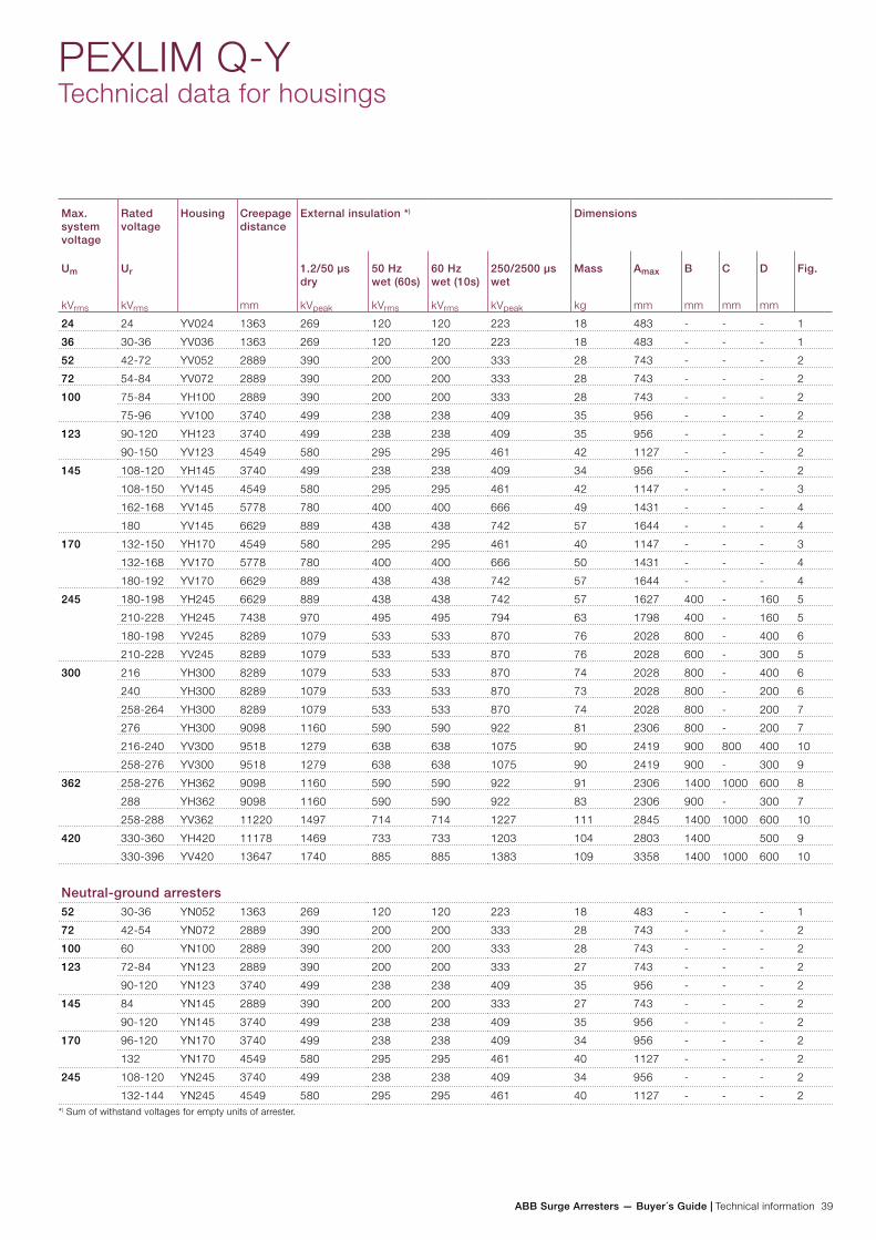
ABB Surge Arresters — Buyer´s Guide | Technical information 39
PEXLIM Q-YTechnical data for housings
Max. system voltage
Rated voltage
Housing Creepage distance
mm
External insulation *) Dimensions
Um
kVrms
Ur
kVrms
1.2/50 µs dry
kVpeak
50 Hz wet (60s)
kVrms
60 Hz wet (10s)
kVrms
250/2500 µs wet
kVpeak
Mass
kg
Amax
mm
B
mm
C
mm
D
mm
Fig.
24 24 YV024 1363 269 120 120 223 18 483 - - - 1
36 30-36 YV036 1363 269 120 120 223 18 483 - - - 1
52 42-72 YV052 2889 390 200 200 333 28 743 - - - 2
72 54-84 YV072 2889 390 200 200 333 28 743 - - - 2
100 75-84 YH100 2889 390 200 200 333 28 743 - - - 2
75-96 YV100 3740 499 238 238 409 35 956 - - - 2
123 90-120 YH123 3740 499 238 238 409 35 956 - - - 2
90-150 YV123 4549 580 295 295 461 42 1127 - - - 2
145 108-120 YH145 3740 499 238 238 409 34 956 - - - 2
108-150 YV145 4549 580 295 295 461 42 1147 - - - 3
162-168 YV145 5778 780 400 400 666 49 1431 - - - 4
180 YV145 6629 889 438 438 742 57 1644 - - - 4
170 132-150 YH170 4549 580 295 295 461 40 1147 - - - 3
132-168 YV170 5778 780 400 400 666 50 1431 - - - 4
180-192 YV170 6629 889 438 438 742 57 1644 - - - 4
245 180-198 YH245 6629 889 438 438 742 57 1627 400 - 160 5
210-228 YH245 7438 970 495 495 794 63 1798 400 - 160 5
180-198 YV245 8289 1079 533 533 870 76 2028 800 - 400 6
210-228 YV245 8289 1079 533 533 870 76 2028 600 - 300 5
300 216 YH300 8289 1079 533 533 870 74 2028 800 - 400 6
240 YH300 8289 1079 533 533 870 73 2028 800 - 200 6
258-264 YH300 8289 1079 533 533 870 74 2028 800 - 200 7
276 YH300 9098 1160 590 590 922 81 2306 800 - 200 7
216-240 YV300 9518 1279 638 638 1075 90 2419 900 800 400 10
258-276 YV300 9518 1279 638 638 1075 90 2419 900 - 300 9
362 258-276 YH362 9098 1160 590 590 922 91 2306 1400 1000 600 8
288 YH362 9098 1160 590 590 922 83 2306 900 - 300 7
258-288 YV362 11220 1497 714 714 1227 111 2845 1400 1000 600 10
420 330-360 YH420 11178 1469 733 733 1203 104 2803 1400 500 9
330-396 YV420 13647 1740 885 885 1383 109 3358 1400 1000 600 10
Neutral-ground arresters52 30-36 YN052 1363 269 120 120 223 18 483 - - - 1
72 42-54 YN072 2889 390 200 200 333 28 743 - - - 2
100 60 YN100 2889 390 200 200 333 28 743 - - - 2
123 72-84 YN123 2889 390 200 200 333 27 743 - - - 2
90-120 YN123 3740 499 238 238 409 35 956 - - - 2
145 84 YN145 2889 390 200 200 333 27 743 - - - 2
90-120 YN145 3740 499 238 238 409 35 956 - - - 2
170 96-120 YN170 3740 499 238 238 409 34 956 - - - 2
132 YN170 4549 580 295 295 461 40 1127 - - - 2
245 108-120 YN245 3740 499 238 238 409 34 956 - - - 2
132-144 YN245 4549 580 295 295 461 40 1127 - - - 2*) Sum of withstand voltages for empty units of arrester.
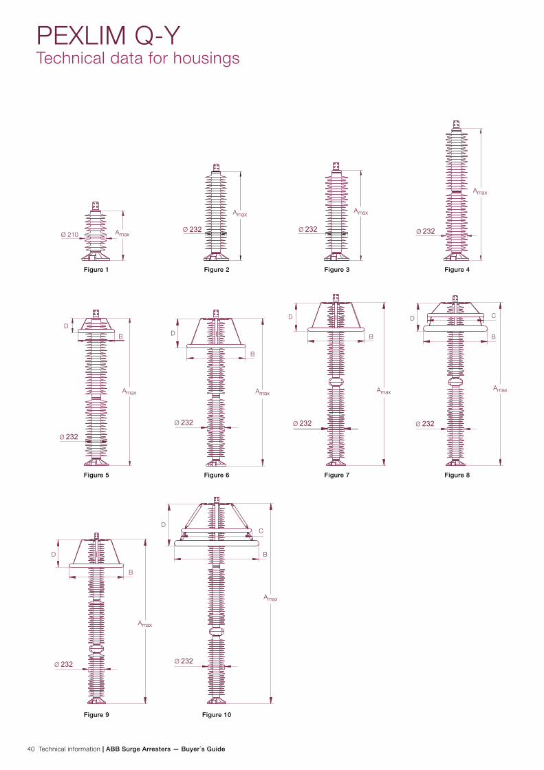
40 Technical information | ABB Surge Arresters — Buyer´s Guide
PEXLIM Q-YTechnical data for housings
Figure 1 Figure 2 Figure 3 Figure 4
Figure 5 Figure 6 Figure 7 Figure 8
Figure 9 Figure 10
B
D
B
D B
D
B
CD
B
D B
CD
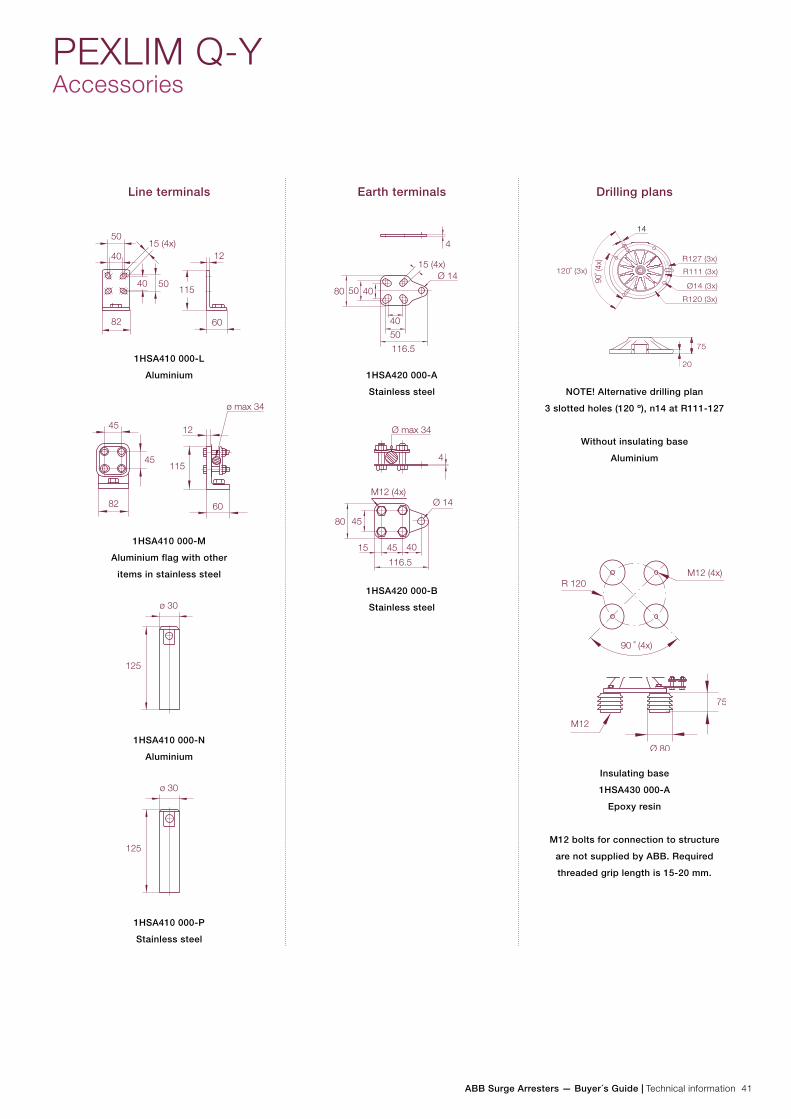
ABB Surge Arresters — Buyer´s Guide | Technical information 41
Line terminals
1HSA410 000-L
Aluminium
1HSA410 000-M
Aluminium flag with other
items in stainless steel
1HSA410 000-N
Aluminium
1HSA410 000-P
Stainless steel
Earth terminals
1HSA420 000-A
Stainless steel
1HSA420 000-B
Stainless steel
Drilling plans
NOTE! Alternative drilling plan
3 slotted holes (120 º), n14 at R111-127
Without insulating base
Aluminium
Insulating base
1HSA430 000-A
Epoxy resin
M12 bolts for connection to structure
are not supplied by ABB. Required
threaded grip length is 15-20 mm.
PEXLIM Q-YAccessories
120˚ (3x)
90˚ (
4x)
14
20
75
R120 (3x)
Ø14 (3x)
R111 (3x)
R127 (3x)
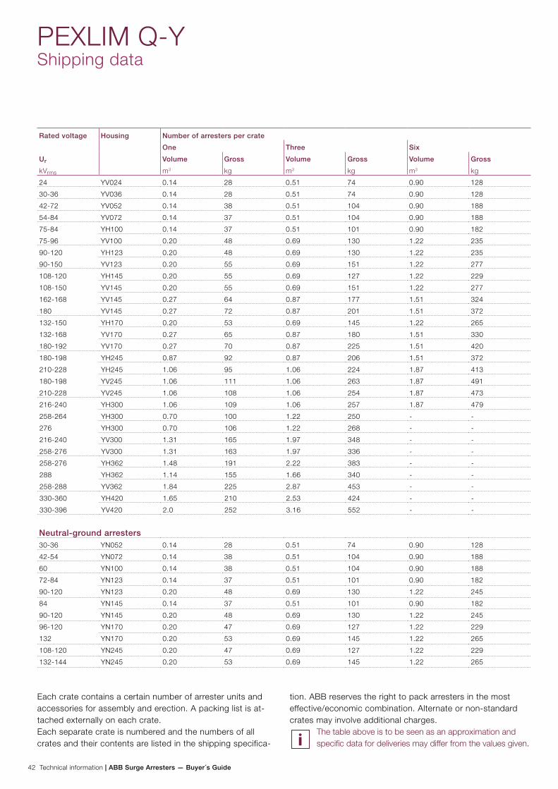
42 Technical information | ABB Surge Arresters — Buyer´s Guide
Rated voltage Housing Number of arresters per crate
One Three Six
Ur
kVrms
Volume
m3
Gross
kg
Volume
m3
Gross
kg
Volume
m3
Gross
kg
24 YV024 0.14 28 0.51 74 0.90 128
30-36 YV036 0.14 28 0.51 74 0.90 128
42-72 YV052 0.14 38 0.51 104 0.90 188
54-84 YV072 0.14 37 0.51 104 0.90 188
75-84 YH100 0.14 37 0.51 101 0.90 182
75-96 YV100 0.20 48 0.69 130 1.22 235
90-120 YH123 0.20 48 0.69 130 1.22 235
90-150 YV123 0.20 55 0.69 151 1.22 277
108-120 YH145 0.20 55 0.69 127 1.22 229
108-150 YV145 0.20 55 0.69 151 1.22 277
162-168 YV145 0.27 64 0.87 177 1.51 324
180 YV145 0.27 72 0.87 201 1.51 372
132-150 YH170 0.20 53 0.69 145 1.22 265
132-168 YV170 0.27 65 0.87 180 1.51 330
180-192 YV170 0.27 70 0.87 225 1.51 420
180-198 YH245 0.87 92 0.87 206 1.51 372
210-228 YH245 1.06 95 1.06 224 1.87 413
180-198 YV245 1.06 111 1.06 263 1.87 491
210-228 YV245 1.06 108 1.06 254 1.87 473
216-240 YH300 1.06 109 1.06 257 1.87 479
258-264 YH300 0.70 100 1.22 250 - -
276 YH300 0.70 106 1.22 268 - -
216-240 YV300 1.31 165 1.97 348 - -
258-276 YV300 1.31 163 1.97 336 - -
258-276 YH362 1.48 191 2.22 383 - -
288 YH362 1.14 155 1.66 340 - -
258-288 YV362 1.84 225 2.87 453 - -
330-360 YH420 1.65 210 2.53 424 - -
330-396 YV420 2.0 252 3.16 552 - -
Neutral-ground arresters30-36 YN052 0.14 28 0.51 74 0.90 128
42-54 YN072 0.14 38 0.51 104 0.90 188
60 YN100 0.14 38 0.51 104 0.90 188
72-84 YN123 0.14 37 0.51 101 0.90 182
90-120 YN123 0.20 48 0.69 130 1.22 245
84 YN145 0.14 37 0.51 101 0.90 182
90-120 YN145 0.20 48 0.69 130 1.22 245
96-120 YN170 0.20 47 0.69 127 1.22 229
132 YN170 0.20 53 0.69 145 1.22 265
108-120 YN245 0.20 47 0.69 127 1.22 229
132-144 YN245 0.20 53 0.69 145 1.22 265
PEXLIM Q-YShipping data
Each crate contains a certain number of arrester units and accessories for assembly and erection. A packing list is at-tached externally on each crate. Each separate crate is numbered and the numbers of all crates and their contents are listed in the shipping specifica-
tion. ABB reserves the right to pack arresters in the most effective/economic combination. Alternate or non-standard crates may involve additional charges.
The table above is to be seen as an approximation and specific data for deliveries may differ from the values given.
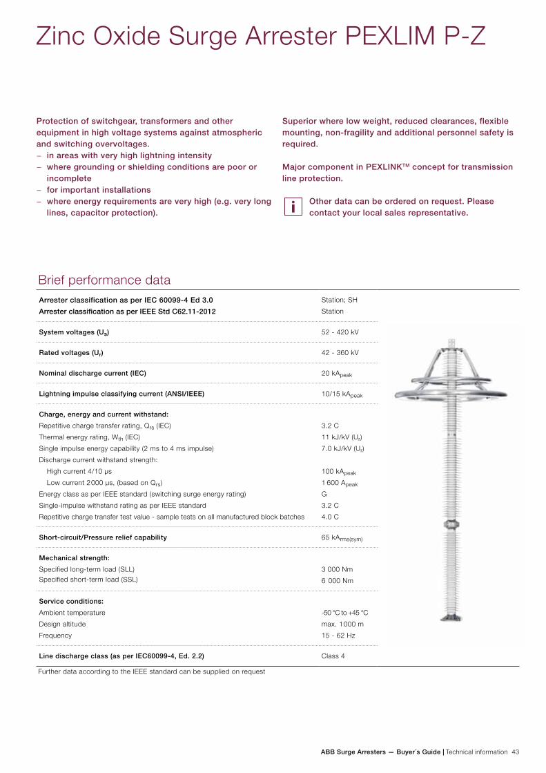
ABB Surge Arresters — Buyer´s Guide | Technical information 43
Zinc Oxide Surge Arrester PEXLIM P-Z
Protection of switchgear, transformers and other equipment in high voltage systems against atmospheric and switching overvoltages.
− in areas with very high lightning intensity − where grounding or shielding conditions are poor or
incomplete − for important installations − where energy requirements are very high (e.g. very long
lines, capacitor protection).
Brief performance dataArrester classification as per IEC 60099-4 Ed 3.0
Arrester classification as per IEEE Std C62.11-2012
Station; SH
Station
System voltages (Us) 52 - 420 kV
Rated voltages (Ur) 42 - 360 kV
Nominal discharge current (IEC) 20 kApeak
Lightning impulse classifying current (ANSI/IEEE) 10/15 kApeak
Charge, energy and current withstand:
Repetitive charge transfer rating, Qrs (IEC)
Thermal energy rating, Wth (IEC)
Single impulse energy capability (2 ms to 4 ms impulse)
Discharge current withstand strength:
High current 4/10 µs
Low current 2 000 µs, (based on Qrs)
Energy class as per IEEE standard (switching surge energy rating)
Single-impulse withstand rating as per IEEE standard
Repetitive charge transfer test value - sample tests on all manufactured block batches
3.2 C
11 kJ/kV (Ur)
7.0 kJ/kV (Ur)
100 kApeak
1 600 Apeak
G
3.2 C
4.0 C
Short-circuit/Pressure relief capability 65 kArms(sym)
Mechanical strength:
Specified long-term load (SLL)Specified short-term load (SSL)
3 000 Nm
6 000 Nm
Service conditions:
Ambient temperature
Design altitude
Frequency
-50 °C to +45 °C
max. 1 000 m
15 - 62 Hz
Line discharge class (as per IEC60099-4, Ed. 2.2) Class 4
Further data according to the IEEE standard can be supplied on request
Superior where low weight, reduced clearances, flexible mounting, non-fragility and additional personnel safety is required.
Major component in PEXLINKTM concept for transmission line protection.
Other data can be ordered on request. Please contact your local sales representative.
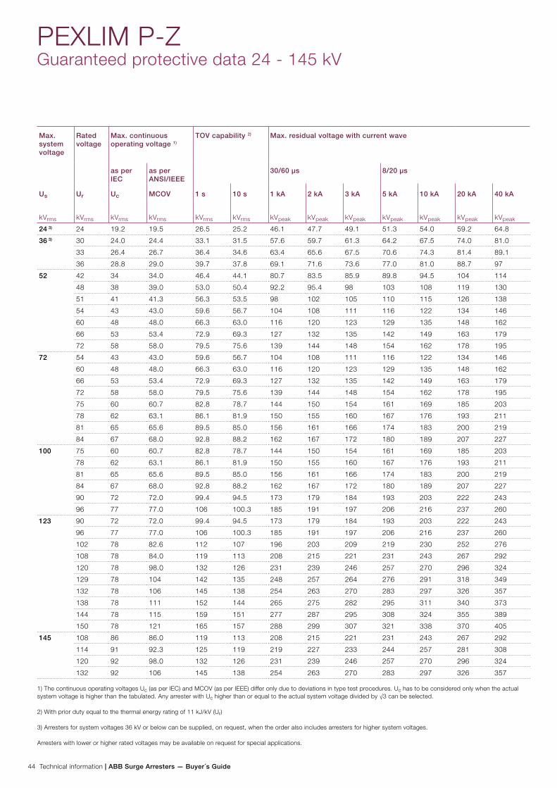
44 Technical information | ABB Surge Arresters — Buyer´s Guide
PEXLIM P-ZGuaranteed protective data 24 - 145 kV
Max. system voltage
Rated voltage
Max. continuous operating voltage 1)
TOV capability 2) Max. residual voltage with current wave
as per IEC
as per ANSI/IEEE
30/60 µs 8/20 µs
Us
kVrms
Ur
kVrms
Uc
kVrms
MCOV
kVrms
1 s
kVrms
10 s
kVrms
1 kA
kVpeak
2 kA
kVpeak
3 kA
kVpeak
5 kA
kVpeak
10 kA
kVpeak
20 kA
kVpeak
40 kA
kVpeak
24 3) 24 19.2 19.5 26.5 25.2 46.1 47.7 49.1 51.3 54.0 59.2 64.8
36 3) 30 24.0 24.4 33.1 31.5 57.6 59.7 61.3 64.2 67.5 74.0 81.0
33 26.4 26.7 36.4 34.6 63.4 65.6 67.5 70.6 74.3 81.4 89.1
36 28.8 29.0 39.7 37.8 69.1 71.6 73.6 77.0 81.0 88.7 97
52 42 34 34.0 46.4 44.1 80.7 83.5 85.9 89.8 94.5 104 114
48 38 39.0 53.0 50.4 92.2 95.4 98 103 108 119 130
51 41 41.3 56.3 53.5 98 102 105 110 115 126 138
54 43 43.0 59.6 56.7 104 108 111 116 122 134 146
60 48 48.0 66.3 63.0 116 120 123 129 135 148 162
66 53 53.4 72.9 69.3 127 132 135 142 149 163 179
72 58 58.0 79.5 75.6 139 144 148 154 162 178 195
72 54 43 43.0 59.6 56.7 104 108 111 116 122 134 146
60 48 48.0 66.3 63.0 116 120 123 129 135 148 162
66 53 53.4 72.9 69.3 127 132 135 142 149 163 179
72 58 58.0 79.5 75.6 139 144 148 154 162 178 195
75 60 60.7 82.8 78.7 144 150 154 161 169 185 203
78 62 63.1 86.1 81.9 150 155 160 167 176 193 211
81 65 65.6 89.5 85.0 156 161 166 174 183 200 219
84 67 68.0 92.8 88.2 162 167 172 180 189 207 227
100 75 60 60.7 82.8 78.7 144 150 154 161 169 185 203
78 62 63.1 86.1 81.9 150 155 160 167 176 193 211
81 65 65.6 89.5 85.0 156 161 166 174 183 200 219
84 67 68.0 92.8 88.2 162 167 172 180 189 207 227
90 72 72.0 99.4 94.5 173 179 184 193 203 222 243
96 77 77.0 106 100.3 185 191 197 206 216 237 260
123 90 72 72.0 99.4 94.5 173 179 184 193 203 222 243
96 77 77.0 106 100.3 185 191 197 206 216 237 260
102 78 82.6 112 107 196 203 209 219 230 252 276
108 78 84.0 119 113 208 215 221 231 243 267 292
120 78 98.0 132 126 231 239 246 257 270 296 324
129 78 104 142 135 248 257 264 276 291 318 349
132 78 106 145 138 254 263 270 283 297 326 357
138 78 111 152 144 265 275 282 295 311 340 373
144 78 115 159 151 277 287 295 308 324 355 389
150 78 121 165 157 288 299 307 321 338 370 405
145 108 86 86.0 119 113 208 215 221 231 243 267 292
114 91 92.3 125 119 219 227 233 244 257 281 308
120 92 98.0 132 126 231 239 246 257 270 296 324
132 92 106 145 138 254 263 270 283 297 326 357
1) The continuous operating voltages Uc (as per IEC) and MCOV (as per IEEE) differ only due to deviations in type test procedures. Uc has to be considered only when the actual system voltage is higher than the tabulated. Any arrester with Uc higher than or equal to the actual system voltage divided by √3 can be selected.
2) With prior duty equal to the thermal energy rating of 11 kJ/kV (Ur)
3) Arresters for system voltages 36 kV or below can be supplied, on request, when the order also includes arresters for higher system voltages.
Arresters with lower or higher rated voltages may be available on request for special applications.

ABB Surge Arresters — Buyer´s Guide | Technical information 45
PEXLIM P-ZGuaranteed protective data 145 - 420 kV
Max. system voltage
Rated voltage
Max. continuous operating voltage 1)
TOV capability 2) Max. residual voltage with current wave
as per IEC
as per ANSI/IEEE
30/60 µs 8/20 µs
Us
kVrms
Ur
kVrms
Uc
kVrms
MCOV
kVrms
1 s
kVrms
10 s
kVrms
1 kA
kVpeak
2 kA
kVpeak
3 kA
kVpeak
5 kA
kVpeak
10 kA
kVpeak
20 kA
kVpeak
40 kA
kVpeak
145 138 92 111 152 144 265 275 282 295 311 340 373
144 92 115 159 151 277 287 295 308 324 355 389
150 92 121 165 157 288 299 307 321 338 370 405
162 92 131 179 170 311 322 331 347 365 400 438
168 92 131 185 176 323 334 344 360 378 414 454
180 92 144 198 189 346 358 368 385 405 444 486
170 132 106 106 145 138 254 263 270 283 297 326 357
144 108 115 159 151 277 287 295 308 324 355 389
150 108 121 165 157 288 299 307 321 338 370 405
162 108 131 179 170 311 322 331 347 365 400 438
168 108 131 185 176 323 334 344 360 378 414 454
180 108 144 198 189 346 358 368 385 405 444 486
192 108 152 212 201 369 382 393 411 432 474 519
245 180 144 144 198 189 346 358 368 385 405 444 486
192 154 154 212 201 369 382 393 411 432 474 519
198 156 160 218 207 381 394 405 424 446 488 535
210 156 170 232 220 404 418 430 449 473 518 567
216 156 175 238 226 415 430 442 462 486 533 584
219 156 177 241 229 421 436 448 469 493 540 592
222 156 179 245 233 427 442 454 475 500 547 600
228 156 180 251 239 438 453 466 488 513 562 616
300 216 173 175 238 226 415 430 442 462 486 533 584
240 191 191 265 252 461 477 491 513 540 592 648
258 191 209 285 270 496 513 528 552 581 636 697
264 191 212 291 277 507 525 540 565 594 651 713
276 191 220 304 289 530 549 564 590 621 680 746
362 258 206 209 285 270 496 513 528 552 581 636 697
264 211 212 291 277 507 525 540 565 594 651 713
276 221 221 304 289 530 549 564 590 621 680 746
288 230 230 318 302 553 573 589 616 648 710 778
420 330 264 267 364 346 634 656 675 706 743 814 891
336 267 272 371 352 645 668 687 719 756 828 908
342 267 277 377 359 657 680 699 732 770 843 924
360 267 291 397 378 691 716 736 770 810 887 972
372 267 301 411 390 714 740 760 796 837 917 1009
378 267 306 417 396 726 751 773 808 851 932 1026
381 267 308 421 400 732 757 779 815 858 939 1034
390 267 315 430 409 749 775 797 834 878 961 1058
396 267 318 437 415 761 787 810 847 891 976 1074
1) The continuous operating voltages Uc (as per IEC) and MCOV (as per IEEE) differ only due to deviations in type test procedures. Uc has to be considered only when the actual system voltage is higher than the tabulated. Any arrester with Uc higher than or equal to the actual system voltage divided by √3 can be selected.
2) With prior duty equal to the thermal energy rating of 11 kJ/kV (Ur)
Arresters with lower or higher rated voltages may be available on request for special applications.
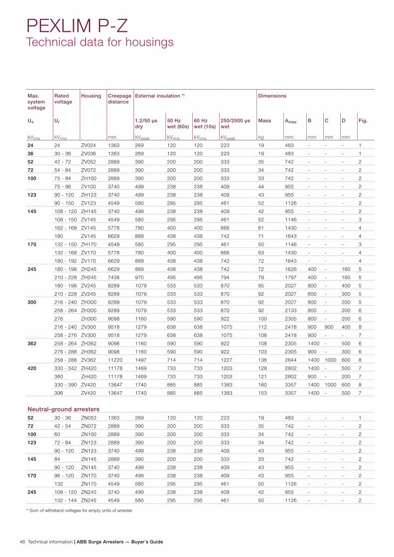
46 Technical information | ABB Surge Arresters — Buyer´s Guide
PEXLIM P-ZTechnical data for housings
Max. system voltage
Rated voltage
Housing Creepage distance
mm
External insulation *) Dimensions
Us
kVrms
Ur
kVrms
1.2/50 µs dry
kVpeak
50 Hz wet (60s)
kVrms
60 Hz wet (10s)
kVrms
250/2500 µs wet
kVpeak
Mass
kg
Amax
mm
B
mm
C
mm
D
mm
Fig.
24 24 ZV024 1363 269 120 120 223 19 483 - - - 1
36 30 - 36 ZV036 1363 269 120 120 223 19 483 - - - 1
52 42 - 72 ZV052 2889 390 200 200 333 35 742 - - - 2
72 54 - 84 ZV072 2889 390 200 200 333 34 742 - - - 2
100 75 - 84 ZH100 2889 390 200 200 333 33 742 - - - 2
75 - 96 ZV100 3740 499 238 238 409 44 955 - - - 2
123 90 - 120 ZH123 3740 499 238 238 409 43 955 - - - 2
90 - 150 ZV123 4549 580 295 295 461 52 1126 - - - 2
145 108 - 120 ZH145 3740 499 238 238 409 42 955 - - - 2
108 - 150 ZV145 4549 580 295 295 461 52 1146 - - - 3
162 - 168 ZV145 5778 780 400 400 666 61 1430 - - - 4
180 ZV145 6629 889 438 438 742 71 1643 - - - 4
170 132 - 150 ZH170 4549 580 295 295 461 50 1146 - - - 3
132 - 168 ZV170 5778 780 400 400 666 63 1430 - - - 4
180 - 192 ZV170 6629 889 438 438 742 72 1643 - - - 4
245 180 - 198 ZH245 6629 889 438 438 742 72 1626 400 - 160 5
210 - 228 ZH245 7438 970 495 495 794 79 1797 400 - 160 5
180 - 198 ZV245 8289 1079 533 533 870 95 2027 800 - 400 5
210 - 228 ZV245 8289 1079 533 533 870 92 2027 600 - 300 5
300 216 - 240 ZH300 8289 1079 533 533 870 92 2027 800 - 200 5
258 - 264 ZH300 8289 1079 533 533 870 92 2133 800 - 200 6
276 ZH300 9098 1160 590 590 922 100 2305 800 - 200 6
216 - 240 ZV300 9518 1279 638 638 1075 112 2418 900 800 400 8
258 - 276 ZV300 9518 1279 638 638 1075 108 2418 900 - - 7
362 258 - 264 ZH362 9098 1160 590 590 922 108 2305 1400 - 500 6
276 - 288 ZH362 9098 1160 590 590 922 103 2305 900 - 300 6
258 - 288 ZV362 11220 1497 714 714 1227 136 2844 1400 1000 600 8
420 330 - 342 ZH420 11178 1469 733 733 1203 128 2802 1400 - 500 7
360 ZH420 11178 1469 733 733 1203 121 2802 900 - 200 7
330 - 390 ZV420 13647 1740 885 885 1383 160 3357 1400 1000 600 8
396 ZV420 13647 1740 885 885 1383 153 3357 1400 - 500 7
Neutral-ground arresters52 30 - 36 ZN052 1363 269 120 120 223 19 483 - - - 1
72 42 - 54 ZN072 2889 390 200 200 333 35 742 - - - 2
100 60 ZN100 2889 390 200 200 333 34 742 - - - 2
123 72 - 84 ZN123 2889 390 200 200 333 34 742 - - - 2
90 - 120 ZN123 3740 499 238 238 409 43 955 - - - 2
145 84 ZN145 2889 390 200 200 333 33 742 - - - 2
90 - 120 ZN145 3740 499 238 238 409 43 955 - - - 2
170 96 - 120 ZN170 3740 499 238 238 409 43 955 - - - 2
132 ZN170 4549 580 295 295 461 50 1126 - - - 2
245 108 - 120 ZN245 3740 499 238 238 409 42 955 - - - 2
132 - 144 ZN245 4549 580 295 295 461 50 1126 - - - 2
*) Sum of withstand voltages for empty units of arrester.
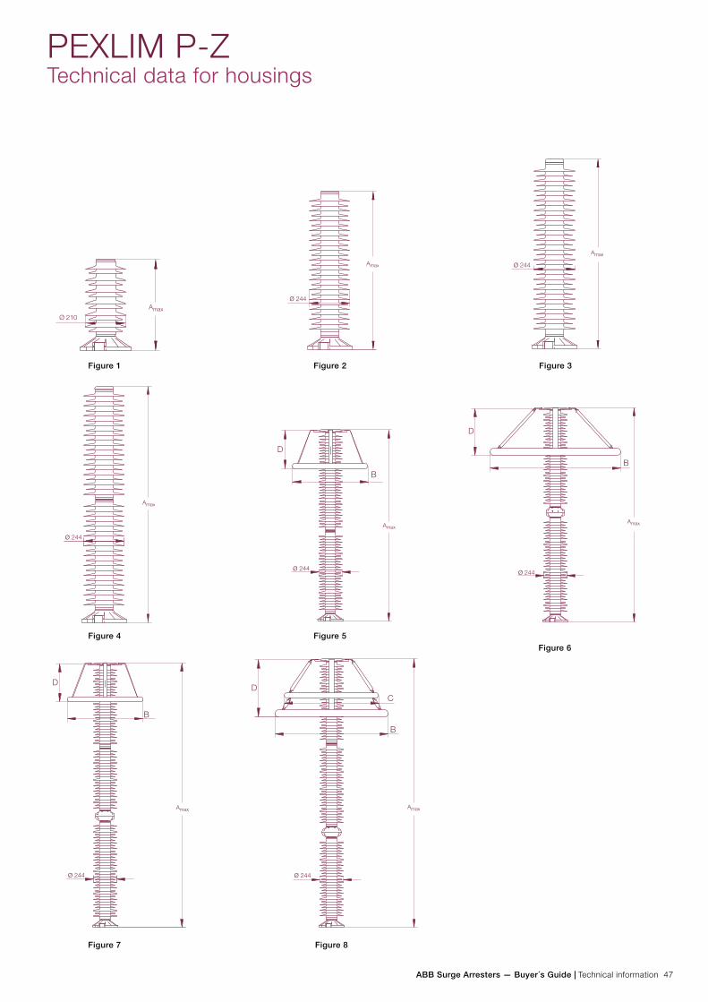
ABB Surge Arresters — Buyer´s Guide | Technical information 47
PEXLIM P-ZTechnical data for housings
Figure 1 Figure 2 Figure 3
Figure 4 Figure 5 Figure 6
Figure 7 Figure 8
ø 244
ø 244
ø 244
ø 244
D
B
ø 244
D
B
ø 244
D
B
ø 244
B
CD
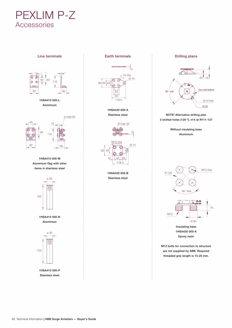
48 Technical information | ABB Surge Arresters — Buyer´s Guide
Line terminals
1HSA410 000-L
Aluminium
1HSA410 000-M
Aluminium flag with other
items in stainless steel
1HSA410 000-N
Aluminium
1HSA410 000-P
Stainless steel
Earth terminals
1HSA420 000-A
Stainless steel
1HSA420 000-B
Stainless steel
Drilling plans
NOTE! Alternative drilling plan
3 slotted holes (120 º), n14 at R111-127
Without insulating base
Aluminium
Insulating base
1HSA430 000-A
Epoxy resin
M12 bolts for connection to structure
are not supplied by ABB. Required
threaded grip length is 15-20 mm.
PEXLIM P-ZAccessories
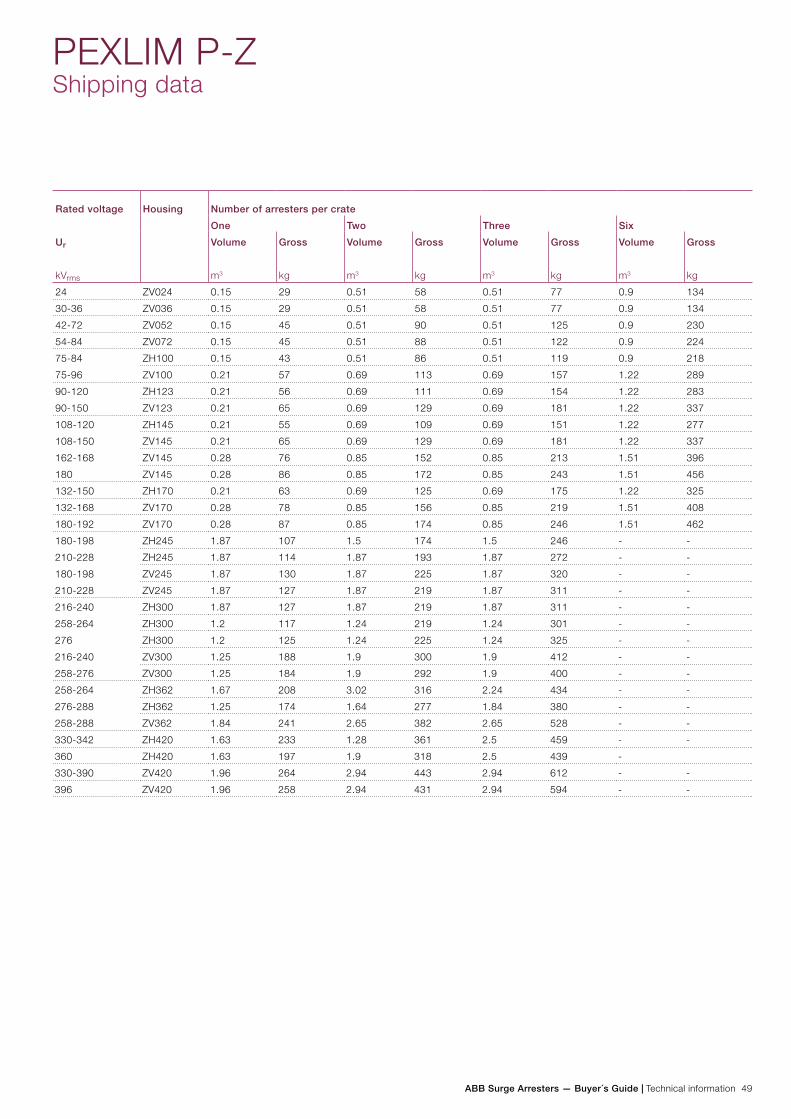
ABB Surge Arresters — Buyer´s Guide | Technical information 49
Rated voltage Housing Number of arresters per crate
One Two Three Six
Ur
kVrms
Volume
m3
Gross
kg
Volume
m3
Gross
kg
Volume
m3
Gross
kg
Volume
m3
Gross
kg
24 ZV024 0.15 29 0.51 58 0.51 77 0.9 134
30-36 ZV036 0.15 29 0.51 58 0.51 77 0.9 134
42-72 ZV052 0.15 45 0.51 90 0.51 125 0.9 230
54-84 ZV072 0.15 45 0.51 88 0.51 122 0.9 224
75-84 ZH100 0.15 43 0.51 86 0.51 119 0.9 218
75-96 ZV100 0.21 57 0.69 113 0.69 157 1.22 289
90-120 ZH123 0.21 56 0.69 111 0.69 154 1.22 283
90-150 ZV123 0.21 65 0.69 129 0.69 181 1.22 337
108-120 ZH145 0.21 55 0.69 109 0.69 151 1.22 277
108-150 ZV145 0.21 65 0.69 129 0.69 181 1.22 337
162-168 ZV145 0.28 76 0.85 152 0.85 213 1.51 396
180 ZV145 0.28 86 0.85 172 0.85 243 1.51 456
132-150 ZH170 0.21 63 0.69 125 0.69 175 1.22 325
132-168 ZV170 0.28 78 0.85 156 0.85 219 1.51 408
180-192 ZV170 0.28 87 0.85 174 0.85 246 1.51 462
180-198 ZH245 1.87 107 1.5 174 1.5 246 - -
210-228 ZH245 1.87 114 1.87 193 1.87 272 - -
180-198 ZV245 1.87 130 1.87 225 1.87 320 - -
210-228 ZV245 1.87 127 1.87 219 1.87 311 - -
216-240 ZH300 1.87 127 1.87 219 1.87 311 - -
258-264 ZH300 1.2 117 1.24 219 1.24 301 - -
276 ZH300 1.2 125 1.24 225 1.24 325 - -
216-240 ZV300 1.25 188 1.9 300 1.9 412 - -
258-276 ZV300 1.25 184 1.9 292 1.9 400 - -
258-264 ZH362 1.67 208 3.02 316 2.24 434 - -
276-288 ZH362 1.25 174 1.64 277 1.84 380 - -
258-288 ZV362 1.84 241 2.65 382 2.65 528 - -
330-342 ZH420 1.63 233 1.28 361 2.5 459 - -
360 ZH420 1.63 197 1.9 318 2.5 439 -
330-390 ZV420 1.96 264 2.94 443 2.94 612 - -
396 ZV420 1.96 258 2.94 431 2.94 594 - -
PEXLIM P-ZShipping data

50 Technical information | ABB Surge Arresters — Buyer´s Guide
Neutral-ground arresters
Rated voltage Housing Number of arresters per crate
One Two Three Six
Ur
kVrms
Volume
m3
Gross
kg
Volume
m3
Gross
kg
Volume
m3
Gross
kg
Volume
m3
Gross
kg
30-36 ZN052 0.15 29 0.51 58 0.51 77 0.9 134
42-54 ZN072 0.15 45 0.51 90 0.51 125 0.9 230
60 ZN100 0.15 44 0.51 88 0.51 122 0.9 224
72-84 ZN123 0.15 44 0.51 88 0.51 122 0.9 224
90-120 ZN123 0.21 56 0.69 111 0.69 154 1.22 283
84 ZN145 0.15 43 0.51 86 0.51 119 0.9 218
90-120 ZN145 0.21 56 0.69 111 0.69 154 1.22 283
96-120 ZN170 0.21 56 0.69 111 0.69 154 1.22 283
132 ZN170 0.21 63 0.69 125 0.69 175 1.22 325
108-120 ZN245 0.21 55 0.69 109 0.69 151 1.22 277
132-144 ZN245 0.21 63 0.69 125 0.69 175 1.22 325
PEXLIM P-ZShipping data
Each crate contains a certain number of arrester units and accessories for assembly and erection. A packing list is at-tached externally on each crate.
Each separate crate is numbered and the numbers of all crates and their contents are listed in the shipping specifica-tion. ABB reserves the right to pack arresters in the most
effective/economic combination. Alternate or non-standard crates may involve additional charges.
The table above is to be seen as an approximation and specific data for deliveries may differ from the values given.
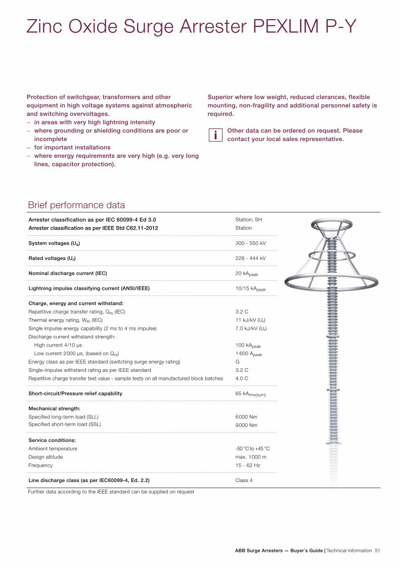
ABB Surge Arresters — Buyer´s Guide | Technical information 51
Zinc Oxide Surge Arrester PEXLIM P-Y
Protection of switchgear, transformers and other equipment in high voltage systems against atmospheric and switching overvoltages.
− in areas with very high lightning intensity − where grounding or shielding conditions are poor or
incomplete − for important installations − where energy requirements are very high (e.g. very long
lines, capacitor protection).
Brief performance dataArrester classification as per IEC 60099-4 Ed 3.0
Arrester classification as per IEEE Std C62.11-2012
Station; SH
Station
System voltages (Us) 300 - 550 kV
Rated voltages (Ur) 228 - 444 kV
Nominal discharge current (IEC) 20 kApeak
Lightning impulse classifying current (ANSI/IEEE) 10/15 kApeak
Charge, energy and current withstand:
Repetitive charge transfer rating, Qrs (IEC)
Thermal energy rating, Wth (IEC)
Single impulse energy capability (2 ms to 4 ms impulse)
Discharge current withstand strength:
High current 4/10 µs
Low current 2 000 µs, (based on Qrs)
Energy class as per IEEE standard (switching surge energy rating)
Single-impulse withstand rating as per IEEE standard
Repetitive charge transfer test value - sample tests on all manufactured block batches
3.2 C
11 kJ/kV (Ur)
7.0 kJ/kV (Ur)
100 kApeak
1 600 Apeak
G
3.2 C
4.0 C
Short-circuit/Pressure relief capability 65 kArms(sym)
Mechanical strength:
Specified long-term load (SLL)Specified short-term load (SSL)
6 000 Nm
9 000 Nm
Service conditions:
Ambient temperature
Design altitude
Frequency
-50 °C to +45 °C
max. 1 000 m
15 - 62 Hz
Line discharge class (as per IEC60099-4, Ed. 2.2) Class 4
Further data according to the IEEE standard can be supplied on request
Superior where low weight, reduced clerances, flexible mounting, non-fragility and additional personnel safety is required.
Other data can be ordered on request. Please contact your local sales representative.
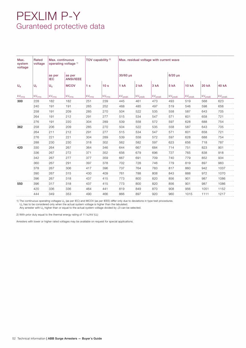
52 Technical information | ABB Surge Arresters — Buyer´s Guide
PEXLIM P-YGuranteed protective data
Max. system voltage
Rated voltage
Max. continuous operating voltage 1)
TOV capability 2) Max. residual voltage with current wave
as per IEC
as per ANSI/IEEE
30/60 µs 8/20 µs
Us
kVrms
Ur
kVrms
Uc
kVrms
MCOV
kVrms
1 s
kVrms
10 s
kVrms
1 kA
kVpeak
2 kA
kVpeak
3 kA
kVpeak
5 kA
kVpeak
10 kA
kVpeak
20 kA
kVpeak
40 kA
kVpeak
300 228 182 182 251 239 445 461 473 493 519 568 623
240 191 191 265 252 468 485 497 519 546 598 656
258 191 209 285 270 504 522 535 558 587 643 705
264 191 212 291 277 515 534 547 571 601 658 721
276 191 220 304 289 539 558 572 597 628 688 754
362 258 206 209 285 270 504 522 535 558 587 643 705
264 211 212 291 277 515 534 547 571 601 658 721
276 221 221 304 289 539 558 572 597 628 688 754
288 230 230 318 302 562 582 597 623 656 718 787
420 330 264 267 364 346 644 667 684 714 751 823 901
336 267 272 371 352 656 679 696 727 765 838 918
342 267 277 377 359 667 691 709 740 779 852 934
360 267 291 397 378 702 728 746 779 819 897 983
378 267 306 417 396 737 764 783 817 860 942 1037
390 267 315 430 409 761 788 808 843 888 972 1070
396 267 318 437 415 773 800 820 856 901 987 1086
550 396 317 318 437 415 773 800 820 856 901 987 1086
420 336 336 464 441 819 849 870 908 956 1051 1152
444 349 353 490 466 866 897 920 960 1015 1111 1217
1) The continuous operating voltages Uc (as per IEC) and MCOV (as per IEEE) differ only due to deviations in type test procedures. Uc has to be considered only when the actual system voltage is higher than the tabulated. Any arrester with Uc higher than or equal to the actual system voltage divided by √3 can be selected.
2) With prior duty equal to the thermal energy rating of 11 kJ/kV (Ur)
Arresters with lower or higher rated voltages may be available on request for special applications.
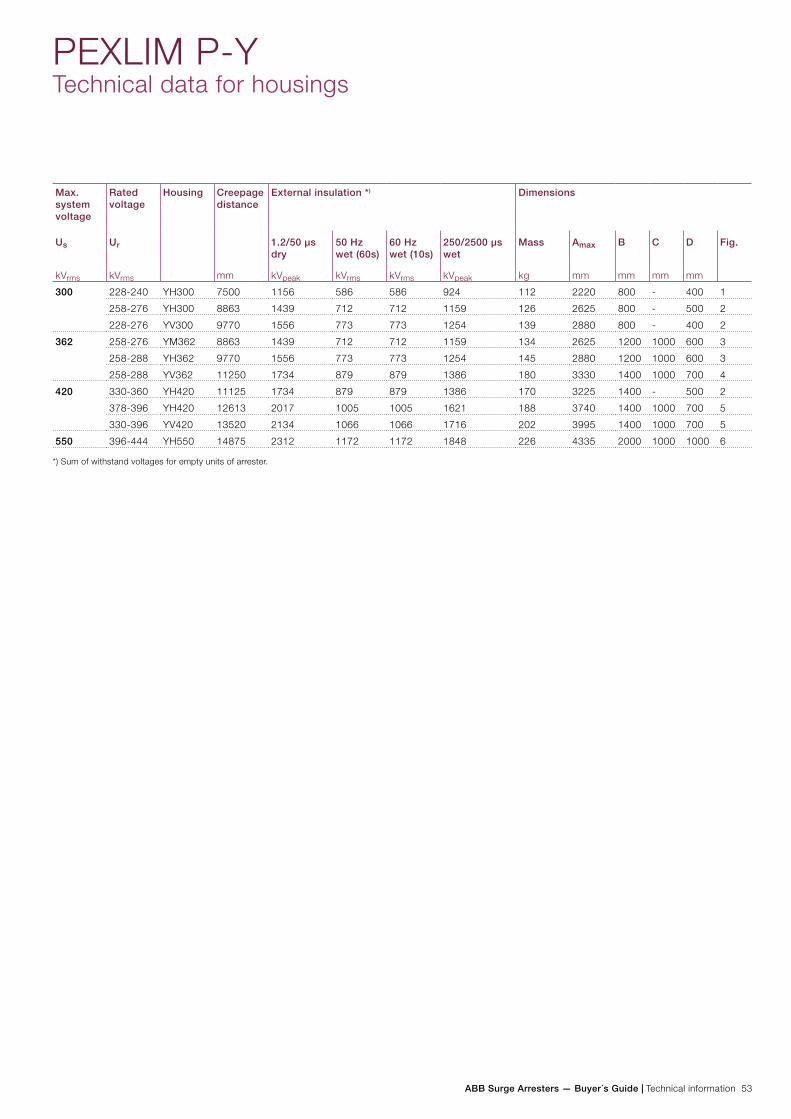
ABB Surge Arresters — Buyer´s Guide | Technical information 53
PEXLIM P-YTechnical data for housings
Max. system voltage
Rated voltage
Housing Creepage distance
mm
External insulation *) Dimensions
Us
kVrms
Ur
kVrms
1.2/50 µs dry
kVpeak
50 Hz wet (60s)
kVrms
60 Hz wet (10s)
kVrms
250/2500 µs wet
kVpeak
Mass
kg
Amax
mm
B
mm
C
mm
D
mm
Fig.
300 228-240 YH300 7500 1156 586 586 924 112 2220 800 - 400 1
258-276 YH300 8863 1439 712 712 1159 126 2625 800 - 500 2
228-276 YV300 9770 1556 773 773 1254 139 2880 800 - 400 2
362 258-276 YM362 8863 1439 712 712 1159 134 2625 1200 1000 600 3
258-288 YH362 9770 1556 773 773 1254 145 2880 1200 1000 600 3
258-288 YV362 11250 1734 879 879 1386 180 3330 1400 1000 700 4
420 330-360 YH420 11125 1734 879 879 1386 170 3225 1400 - 500 2
378-396 YH420 12613 2017 1005 1005 1621 188 3740 1400 1000 700 5
330-396 YV420 13520 2134 1066 1066 1716 202 3995 1400 1000 700 5
550 396-444 YH550 14875 2312 1172 1172 1848 226 4335 2000 1000 1000 6
*) Sum of withstand voltages for empty units of arrester.
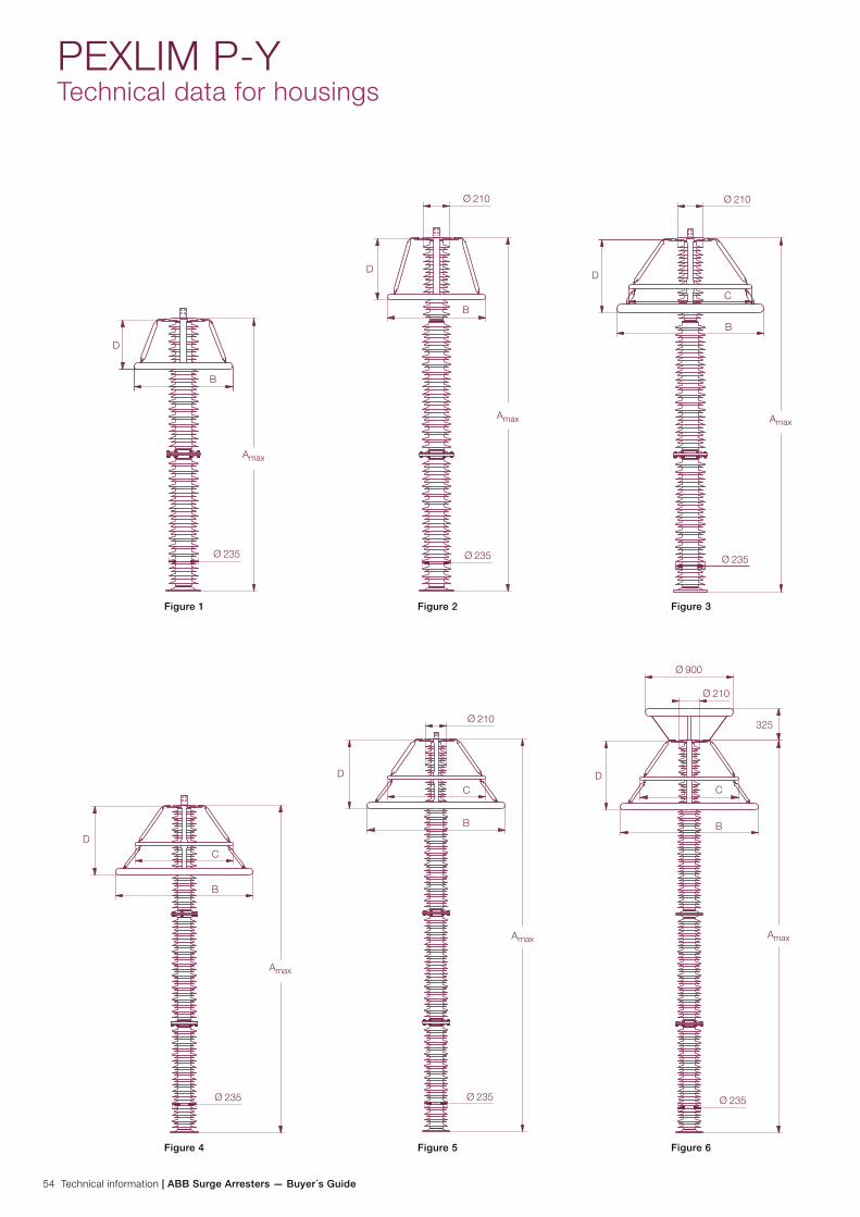
54 Technical information | ABB Surge Arresters — Buyer´s Guide
PEXLIM P-YTechnical data for housings
Figure 1 Figure 2 Figure 3
Figure 4 Figure 5 Figure 6
235
D
B
210
235
D
B
210
235
D
C
B
235
D
C
B
235
D
C
B
210
235
DC
B
210
900
325
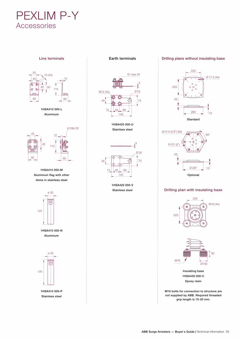
ABB Surge Arresters — Buyer´s Guide | Technical information 55
297
14.5 (5.8”) (6x)
12
32
R127 (5”)
60°
Line terminals Earth terminals Drilling plans without insulating base
1HSA410 000-L
Aluminium
1HSA410 000-M
Aluminium flag with other
items in stainless steel
1HSA410 000-N
Aluminium
1HSA410 000-P
Stainless steel
1HSA420 000-U
Stainless steel
1HSA420 000-V
Stainless steel
Standard
Optional
Drilling plan with insulating base
Insulating base
1HSA430 000-C
Epoxy resin
M16 bolts for connection to structure are not supplied by ABB. Required threaded
grip length is 15-20 mm.
PEXLIM P-YAccessories
15
45
M12 (4x)
45
75
4
69
18
max 34
145
18
75
45
45
6915
145
4
17.5 (4x)
225
225
280
32
12
M16 (4x)
80
Ø100
225
M16
225

56 Technical information | ABB Surge Arresters — Buyer´s Guide
Rated voltage Housing Number of arresters per crate
One Three
Ur
kVrms
Volume
m3
Gross
kg
Volume
m3
Gross
kg
288-240 YH300 1.18 162 1.18 386
258-276 YH300 1.18 176 1.18 429
228-276 YV300 1.18 189 1.18 467
258-276 YM362 1.69 230 1.94 499
258-288 YH362 1.69 240 1.94 531
330-360 YH420 1.85 280 2.19 621
258-288 YV362 1.85 290 2.19 652
378-396 YH420 1.85 298 2.19 675
330-396 YV420 1.85 312 2.19 716
396-444 YH550 3.38 426 3.38 879
PEXLIM P-YShipping data
Each crate contains a certain number of arrester units and accessories for assembly and erection. A packing list is at-tached externally on each crate.
Each separate crate is numbered and the numbers of all crates and their contents are listed in the shipping specification. ABB reserves
the right to pack arresters in the most effective/economic com-bination. Alternate or non-standard crates may involve additional charges.
The table above is to be seen as an approximation and specific data for deliveries may differ from the values given.
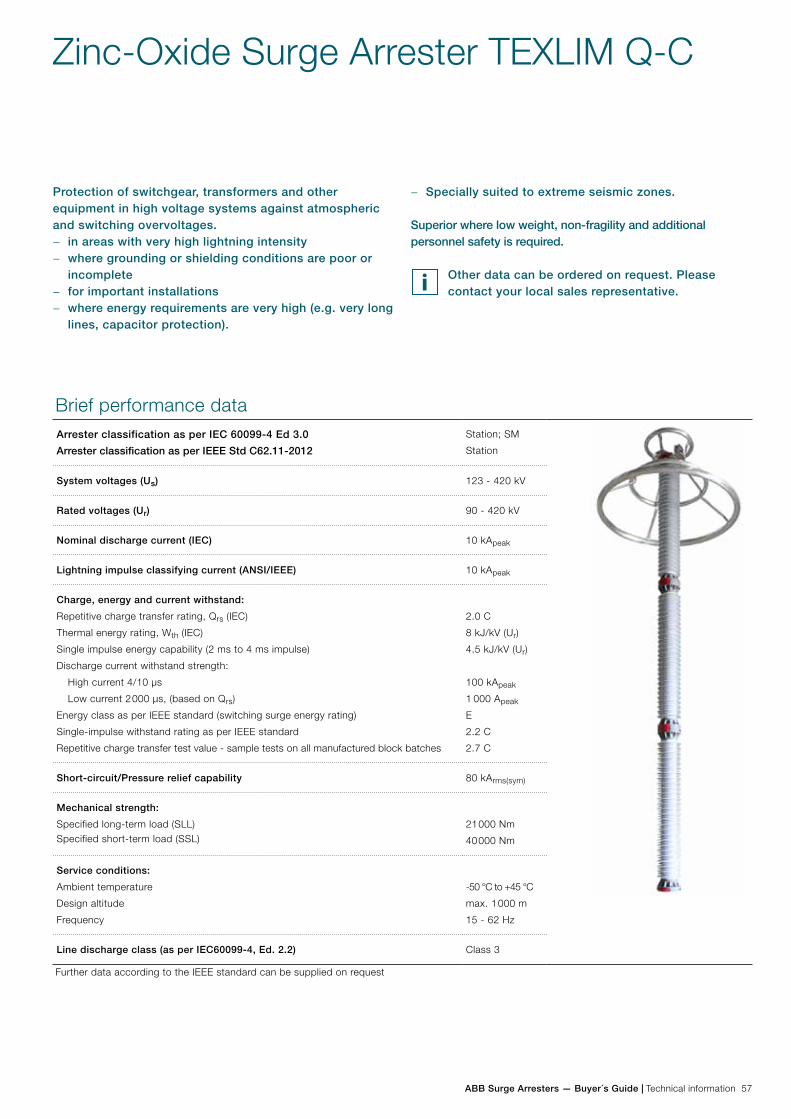
ABB Surge Arresters — Buyer´s Guide | Technical information 57
− Specially suited to extreme seismic zones.
Superior where low weight, non-fragility and additional personnel safety is required.
Other data can be ordered on request. Please contact your local sales representative.
Zinc-Oxide Surge Arrester TEXLIM Q-C
Protection of switchgear, transformers and other equipment in high voltage systems against atmospheric and switching overvoltages.
− in areas with very high lightning intensity − where grounding or shielding conditions are poor or
incomplete − for important installations − where energy requirements are very high (e.g. very long
lines, capacitor protection).
Brief performance dataArrester classification as per IEC 60099-4 Ed 3.0
Arrester classification as per IEEE Std C62.11-2012
Station; SM
Station
System voltages (Us) 123 - 420 kV
Rated voltages (Ur) 90 - 420 kV
Nominal discharge current (IEC) 10 kApeak
Lightning impulse classifying current (ANSI/IEEE) 10 kApeak
Charge, energy and current withstand:
Repetitive charge transfer rating, Qrs (IEC)
Thermal energy rating, Wth (IEC)
Single impulse energy capability (2 ms to 4 ms impulse)
Discharge current withstand strength:
High current 4/10 µs
Low current 2 000 µs, (based on Qrs)
Energy class as per IEEE standard (switching surge energy rating)
Single-impulse withstand rating as per IEEE standard
Repetitive charge transfer test value - sample tests on all manufactured block batches
2.0 C
8 kJ/kV (Ur)
4.5 kJ/kV (Ur)
100 kApeak
1 000 Apeak
E
2.2 C
2.7 C
Short-circuit/Pressure relief capability 80 kArms(sym)
Mechanical strength:
Specified long-term load (SLL)Specified short-term load (SSL)
21 000 Nm
40 000 Nm
Service conditions:
Ambient temperature
Design altitude
Frequency
-50 °C to +45 °C
max. 1 000 m
15 - 62 Hz
Line discharge class (as per IEC60099-4, Ed. 2.2) Class 3
Further data according to the IEEE standard can be supplied on request

58 Technical information | ABB Surge Arresters — Buyer´s Guide
TEXLIM Q-CGuaranteed protective data
Max. system voltage
Rated voltage
Max. continuous operating voltage 1)
TOV capability 2) Max. residual voltage with current wave
as per IEC
as per ANSI/IEEE
30/60 µs 8/20 µs
Us
kVrms
Ur
kVrms
Uc
kVrms
MCOV
kVrms
1 s
kVrms
10 s
kVrms
0.5 kA
kVpeak
1 kA
kVpeak
2 kA
kVpeak
5 kA
kVpeak
10 kA
kVpeak
20 kA
kVpeak
40 kA
kVpeak
123 090 72 72.0 98.5 92.7 173 178 185 201 212 233 261
096 77 77.0 105 98.9 185 190 197 215 226 249 278
102 78 82.0 111 105 196 202 210 228 240 264 295
108 78 84.0 118 111 208 214 222 242 254 280 313
120 78 98.0 131 123 231 237 247 268 282 311 347
129 78 104 141 132 248 255 265 288 304 334 373
132 78 106 144 136 254 261 271 295 311 342 382
138 78 111 151 142 265 273 284 309 325 357 399
144 78 115 157 148 277 285 296 322 339 373 417
150 78 121 164 154 288 297 308 335 353 388 434
145 108 86 86.0 118 111 208 214 222 242 254 280 313
120 92 98.0 131 123 231 237 247 268 282 311 347
132 92 106 144 136 254 261 271 295 311 342 382
138 92 111 151 142 265 273 284 309 325 357 399
144 92 115 157 148 277 285 296 322 339 373 417
150 92 121 164 154 288 297 308 335 353 388 434
162 92 131 177 167 312 320 333 362 381 419 469
168 92 131 183 173 323 332 345 376 395 435 486
170 132 106 106 144 136 254 261 271 295 311 342 382
144 108 115 157 148 277 285 296 322 339 373 417
150 108 121 164 154 288 297 308 335 353 388 434
162 108 131 177 167 312 320 333 362 381 419 469
168 108 131 183 173 323 332 345 376 395 435 486
180 108 144 197 185 346 356 370 402 423 466 521
192 108 152 210 197 369 380 394 429 452 497 555
245 180 144 144 197 185 346 356 370 402 423 466 521
192 154 154 210 197 369 380 394 429 452 497 555
198 156 160 216 204 381 391 407 443 466 512 573
210 156 170 229 216 404 415 431 469 494 543 608
216 156 174 236 222 415 427 444 483 508 559 625
219 156 177 239 225 421 433 450 489 515 567 634
222 156 179 243 228 427 439 456 496 522 574 642
228 156 180 249 235 438 451 468 510 536 590 660
1) The continuous operating voltages Uc (as per IEC) and MCOV (as per IEEE) differ only due to deviations in type test procedures. Uc has to be considered only when the actual system voltage is higher than the tabulated. Any arrester with Uc higher than or equal to the actual system voltage divided by √3 can be selected.
2) With prior duty equal to the thermal energy rating of 11 kJ/kV (Ur).
Arresters with lower or higher rated voltages may be available on request for special applications.
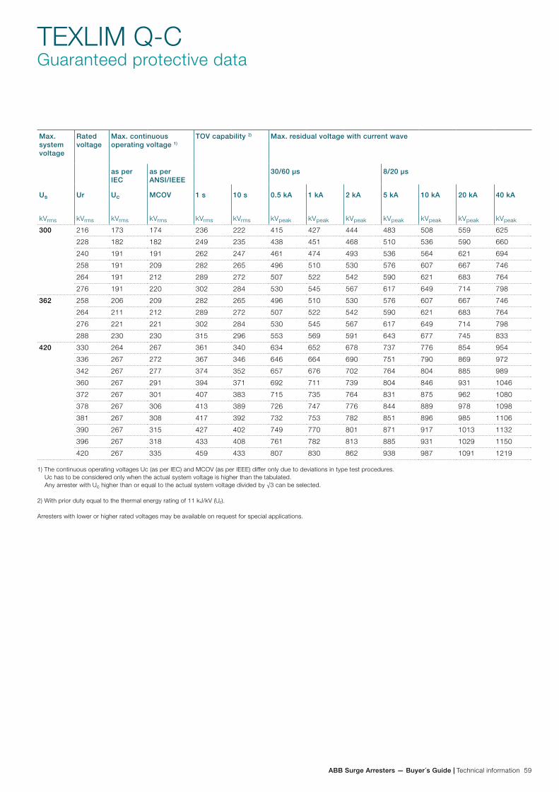
ABB Surge Arresters — Buyer´s Guide | Technical information 59
TEXLIM Q-CGuaranteed protective data
Max. system voltage
Rated voltage
Max. continuous operating voltage 1)
TOV capability 2) Max. residual voltage with current wave
as per IEC
as per ANSI/IEEE
30/60 µs 8/20 µs
Us
kVrms
Ur
kVrms
Uc
kVrms
MCOV
kVrms
1 s
kVrms
10 s
kVrms
0.5 kA
kVpeak
1 kA
kVpeak
2 kA
kVpeak
5 kA
kVpeak
10 kA
kVpeak
20 kA
kVpeak
40 kA
kVpeak
300 216 173 174 236 222 415 427 444 483 508 559 625
228 182 182 249 235 438 451 468 510 536 590 660
240 191 191 262 247 461 474 493 536 564 621 694
258 191 209 282 265 496 510 530 576 607 667 746
264 191 212 289 272 507 522 542 590 621 683 764
276 191 220 302 284 530 545 567 617 649 714 798
362 258 206 209 282 265 496 510 530 576 607 667 746
264 211 212 289 272 507 522 542 590 621 683 764
276 221 221 302 284 530 545 567 617 649 714 798
288 230 230 315 296 553 569 591 643 677 745 833
420 330 264 267 361 340 634 652 678 737 776 854 954
336 267 272 367 346 646 664 690 751 790 869 972
342 267 277 374 352 657 676 702 764 804 885 989
360 267 291 394 371 692 711 739 804 846 931 1046
372 267 301 407 383 715 735 764 831 875 962 1080
378 267 306 413 389 726 747 776 844 889 978 1098
381 267 308 417 392 732 753 782 851 896 985 1106
390 267 315 427 402 749 770 801 871 917 1013 1132
396 267 318 433 408 761 782 813 885 931 1029 1150
420 267 335 459 433 807 830 862 938 987 1091 1219
1) The continuous operating voltages Uc (as per IEC) and MCOV (as per IEEE) differ only due to deviations in type test procedures. Uc has to be considered only when the actual system voltage is higher than the tabulated. Any arrester with Uc higher than or equal to the actual system voltage divided by √3 can be selected.
2) With prior duty equal to the thermal energy rating of 11 kJ/kV (Ur).
Arresters with lower or higher rated voltages may be available on request for special applications.
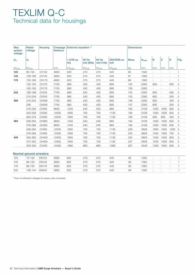
60 Technical information | ABB Surge Arresters — Buyer´s Guide
TEXLIM Q-CTechnical data for housings
Max. system voltage
Rated voltage
Housing Creepage distance
mm
External insulation *) Dimensions
Us
kVrms
Ur
kVrms
1.2/50 µs dry
kVpeak
50 Hz wet (60s)
kVrms
60 Hz wet (10s)
kVrms
250/2500 µs wet
kVpeak
Mass
kg
Amax
mm
B
mm
C
mm
D
mm
Fig.
123 90-150 CV123 4800 620 270 270 440 95 1562 - - - 1
145 108-168 CV145 4800 620 270 270 440 97 1562 - - - 1
170 132-180 CH170 4800 620 270 270 440 98 1562 - - - 1
132-150 CV170 7700 980 430 430 690 125 2282 600 - 300 2
162-192 CV170 7700 980 430 430 690 128 2282 - - - 1
245 180-198 CV245 7700 980 430 430 690 132 2282 800 - 400 2
210-228 CV245 7700 980 430 430 690 133 2282 600 - 300 2
300 216-240 CH300 7700 980 430 430 690 136 2282 900 - 400 2
258 CH300 7700 980 430 430 690 137 2282 800 - 200 2
216-228 CV300 9600 1240 540 540 880 190 3109 1200 1000 800 3
240-258 CV300 12500 1600 700 700 1130 195 3109 1200 1000 600 3
264-276 CV300 12500 1600 700 700 1130 190 3109 900 800 400 3
362 258-264 CH362 9600 1240 540 540 880 194 3109 1400 1000 600 3
276-288 CH362 9600 1240 540 540 880 195 3109 1200 1000 600 3
258-264 CV362 12500 1600 700 700 1130 226 3829 1600 1000 1200 3
276-288 CV362 12500 1600 700 700 1130 225 3829 1400 1000 700 3
420 330-360 CH420 12500 1600 700 700 1130 232 3829 1200 1000 800 3
372-420 CH420 12500 1600 700 700 1130 237 3829 1200 1000 600 3
330-420 CV420 15400 1960 860 860 1380 267 4549 1200 1000 800 3
123 72-120 CN123 4800 620 270 270 440 92 1562 - - - 1
145 84-120 CN145 4800 620 270 270 440 92 1562 - - - 1
170 96-132 CN170 4800 620 270 270 440 93 1562 - - - 1
245 108-144 CN245 4800 620 270 270 440 94 1562 - - - 1
Neutral-ground arresters
*) Sum of withstand voltages for empty units of arrester.
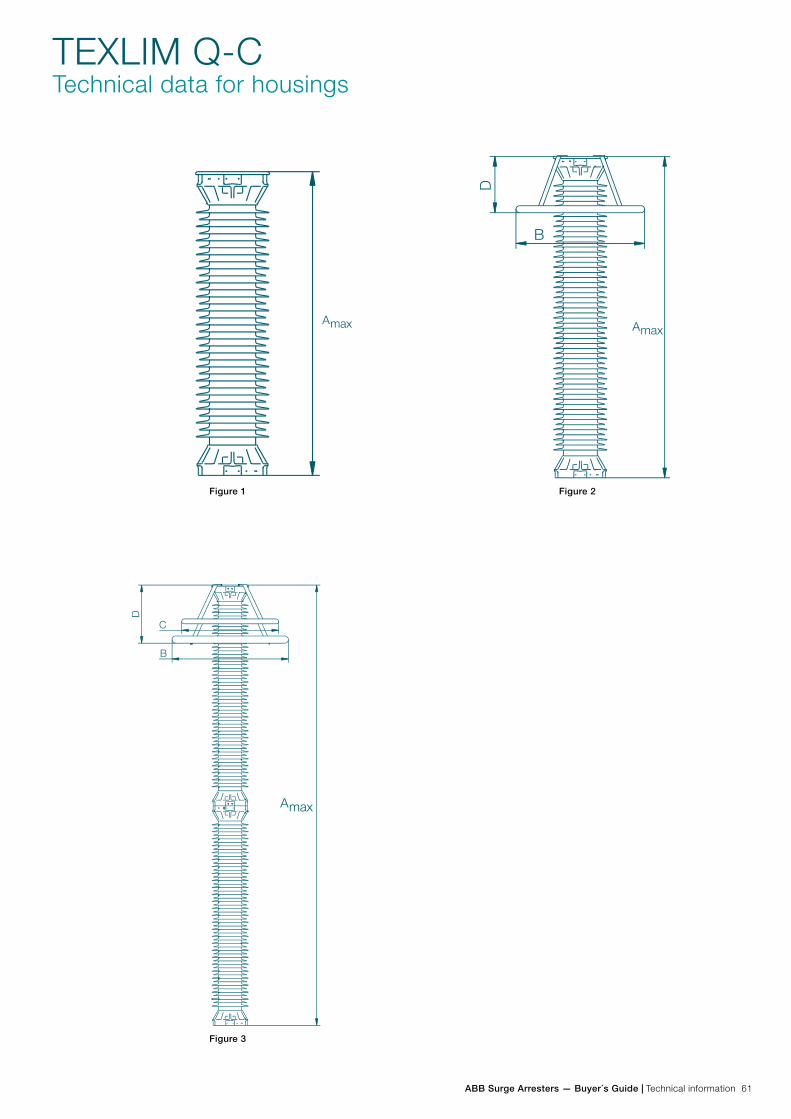
ABB Surge Arresters — Buyer´s Guide | Technical information 61
Figure 1 Figure 2
Figure 3 Figure 4
TEXLIM Q-CTechnical data for housings
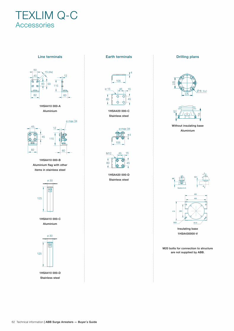
62 Technical information | ABB Surge Arresters — Buyer´s Guide
TEXLIM Q-CAccessories
Line terminals
1HSA410 000-A
Aluminium
1HSA410 000-B
Aluminium flag with other
items in stainless steel
1HSA410 000-C
Aluminium
1HSA410 000-D
Stainless steel
Earth terminals
1HSA420 000-C
Stainless steel
1HSA420 000-D
Stainless steel
Drilling plans
Without insulating base
Aluminium
Insulating base
1HSA430000-V
M20 bolts for connection to structure are not supplied by ABB.
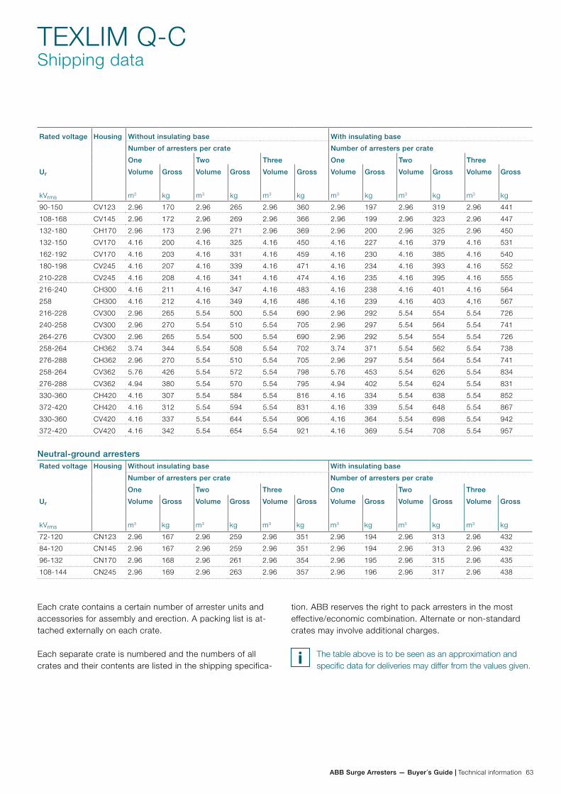
ABB Surge Arresters — Buyer´s Guide | Technical information 63
TEXLIM Q-CShipping data
Rated voltage
Ur
kVrms
Housing Without insulating base With insulating base
Number of arresters per crate Number of arresters per crate
One Two Three One Two Three
Volume
m3
Gross
kg
Volume
m3
Gross
kg
Volume
m3
Gross
kg
Volume
m3
Gross
kg
Volume
m3
Gross
kg
Volume
m3
Gross
kg
90-150 CV123 2.96 170 2.96 265 2.96 360 2.96 197 2.96 319 2.96 441
108-168 CV145 2.96 172 2.96 269 2.96 366 2.96 199 2.96 323 2.96 447
132-180 CH170 2.96 173 2.96 271 2.96 369 2.96 200 2.96 325 2.96 450
132-150 CV170 4.16 200 4.16 325 4.16 450 4.16 227 4.16 379 4.16 531
162-192 CV170 4.16 203 4.16 331 4.16 459 4.16 230 4.16 385 4.16 540
180-198 CV245 4.16 207 4.16 339 4.16 471 4.16 234 4.16 393 4.16 552
210-228 CV245 4.16 208 4.16 341 4.16 474 4.16 235 4.16 395 4.16 555
216-240 CH300 4.16 211 4.16 347 4.16 483 4.16 238 4.16 401 4.16 564
258 CH300 4.16 212 4.16 349 4,16 486 4.16 239 4.16 403 4,16 567
216-228 CV300 2.96 265 5.54 500 5.54 690 2.96 292 5.54 554 5.54 726
240-258 CV300 2.96 270 5.54 510 5.54 705 2.96 297 5.54 564 5.54 741
264-276 CV300 2.96 265 5.54 500 5.54 690 2.96 292 5.54 554 5.54 726
258-264 CH362 3.74 344 5.54 508 5.54 702 3.74 371 5.54 562 5.54 738
276-288 CH362 2.96 270 5.54 510 5.54 705 2.96 297 5.54 564 5.54 741
258-264 CV362 5.76 426 5.54 572 5.54 798 5.76 453 5.54 626 5.54 834
276-288 CV362 4.94 380 5.54 570 5.54 795 4.94 402 5.54 624 5.54 831
330-360 CH420 4.16 307 5.54 584 5.54 816 4.16 334 5.54 638 5.54 852
372-420 CH420 4.16 312 5.54 594 5.54 831 4.16 339 5.54 648 5.54 867
330-360 CV420 4.16 337 5.54 644 5.54 906 4.16 364 5.54 698 5.54 942
372-420 CV420 4.16 342 5.54 654 5.54 921 4.16 369 5.54 708 5.54 957
Each crate contains a certain number of arrester units and accessories for assembly and erection. A packing list is at-tached externally on each crate.
Each separate crate is numbered and the numbers of all crates and their contents are listed in the shipping specifica-
tion. ABB reserves the right to pack arresters in the most effective/economic combination. Alternate or non-standard crates may involve additional charges.
The table above is to be seen as an approximation and specific data for deliveries may differ from the values given.
Rated voltage
Ur
kVrms
Housing Without insulating base With insulating base
Number of arresters per crate Number of arresters per crate
One Two Three One Two Three
Volume
m3
Gross
kg
Volume
m3
Gross
kg
Volume
m3
Gross
kg
Volume
m3
Gross
kg
Volume
m3
Gross
kg
Volume
m3
Gross
kg
72-120 CN123 2.96 167 2.96 259 2.96 351 2.96 194 2.96 313 2.96 432
84-120 CN145 2.96 167 2.96 259 2.96 351 2.96 194 2.96 313 2.96 432
96-132 CN170 2.96 168 2.96 261 2.96 354 2.96 195 2.96 315 2.96 435
108-144 CN245 2.96 169 2.96 263 2.96 357 2.96 196 2.96 317 2.96 438
Neutral-ground arresters
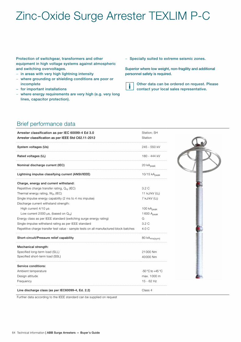
64 Technical information | ABB Surge Arresters — Buyer´s Guide
Brief performance dataArrester classification as per IEC 60099-4 Ed 3.0
Arrester classification as per IEEE Std C62.11-2012
Station; SH
Station
System voltages (Us) 245 - 550 kV
Rated voltages (Ur) 180 - 444 kV
Nominal discharge current (IEC) 20 kApeak
Lightning impulse classifying current (ANSI/IEEE) 10/15 kApeak
Charge, energy and current withstand:
Repetitive charge transfer rating, Qrs (IEC)
Thermal energy rating, Wth (IEC)
Single impulse energy capability (2 ms to 4 ms impulse)
Discharge current withstand strength:
High current 4/10 µs
Low current 2 000 µs, (based on Qrs)
Energy class as per IEEE standard (switching surge energy rating)
Single-impulse withstand rating as per IEEE standard
Repetitive charge transfer test value - sample tests on all manufactured block batches
3.2 C
11 kJ/kV (Ur)
7 kJ/kV (Ur)
100 kApeak
1 600 Apeak
G
3.2 C
4.0 C
Short-circuit/Pressure relief capability 80 kArms(sym)
Mechanical strength:
Specified long-term load (SLL)Specified short-term load (SSL)
21 000 Nm
40 000 Nm
Service conditions:
Ambient temperature
Design altitude
Frequency
-50 °C to +45 °C
max. 1 000 m
15 - 62 Hz
Line discharge class (as per IEC60099-4, Ed. 2.2) Class 4
Further data according to the IEEE standard can be supplied on request
− Specially suited to extreme seismic zones.
Superior where low weight, non-fragility and additional personnel safety is required.
Other data can be ordered on request. Please contact your local sales representative.
Zinc-Oxide Surge Arrester TEXLIM P-C
Protection of switchgear, transformers and other equipment in high voltage systems against atmospheric and switching overvoltages.
− in areas with very high lightning intensity − where grounding or shielding conditions are poor or
incomplete − for important installations − where energy requirements are very high (e.g. very long
lines, capacitor protection).
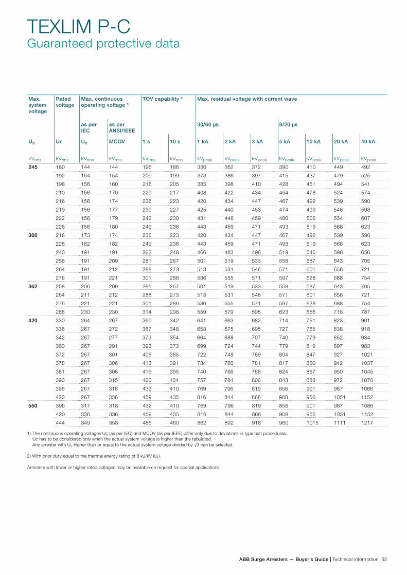
ABB Surge Arresters — Buyer´s Guide | Technical information 65
TEXLIM P-CGuaranteed protective data
Max. system voltage
Rated voltage
Max. continuous operating voltage 1)
TOV capability 2) Max. residual voltage with current wave
as per IEC
as per ANSI/IEEE
30/60 µs 8/20 µs
Us
kVrms
Ur
kVrms
Uc
kVrms
MCOV
kVrms
1 s
kVrms
10 s
kVrms
1 kA
kVpeak
2 kA
kVpeak
3 kA
kVpeak
5 kA
kVpeak
10 kA
kVpeak
20 kA
kVpeak
40 kA
kVpeak
245 180 144 144 196 186 350 362 372 390 410 449 492
192 154 154 209 199 373 386 397 415 437 479 525
198 156 160 216 205 385 398 410 428 451 494 541
210 156 170 229 217 408 422 434 454 478 524 574
216 156 174 236 223 420 434 447 467 492 539 590
219 156 177 239 227 425 440 453 474 499 546 598
222 156 179 242 230 431 446 459 480 506 554 607
228 156 180 249 236 443 459 471 493 519 568 623
300 216 173 174 236 223 420 434 447 467 492 539 590
228 182 182 249 236 443 459 471 493 519 568 623
240 191 191 262 248 466 483 496 519 546 598 656
258 191 209 281 267 501 519 533 558 587 643 705
264 191 212 288 273 513 531 546 571 601 658 721
276 191 221 301 286 536 555 571 597 628 688 754
362 258 206 209 281 267 501 519 533 558 587 643 705
264 211 212 288 273 513 531 546 571 601 658 721
276 221 221 301 286 536 555 571 597 628 688 754
288 230 230 314 298 559 579 595 623 656 718 787
420 330 264 267 360 342 641 663 682 714 751 823 901
336 267 272 367 348 653 675 695 727 765 838 918
342 267 277 373 354 664 688 707 740 779 852 934
360 267 291 393 373 699 724 744 779 819 897 983
372 267 301 406 385 722 748 769 804 847 927 1021
378 267 306 413 391 734 760 781 817 860 942 1037
381 267 308 416 395 740 766 788 824 867 950 1045
390 267 315 426 404 757 784 806 843 888 972 1070
396 267 318 432 410 769 796 819 856 901 987 1086
420 267 336 459 435 816 844 868 908 956 1051 1152
550 396 317 318 432 410 769 796 819 856 901 987 1086
420 336 336 459 435 816 844 868 908 956 1051 1152
444 349 353 485 460 862 892 918 960 1015 1111 1217
1) The continuous operating voltages Uc (as per IEC) and MCOV (as per IEEE) differ only due to deviations in type test procedures. Uc has to be considered only when the actual system voltage is higher than the tabulated. Any arrester with Uc higher than or equal to the actual system voltage divided by √3 can be selected.
2) With prior duty equal to the thermal energy rating of 8 kJ/kV (Ur).
Arresters with lower or higher rated voltages may be available on request for special applications.
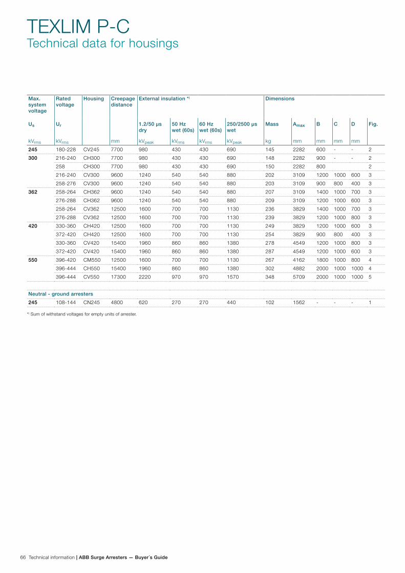
66 Technical information | ABB Surge Arresters — Buyer´s Guide
TEXLIM P-CTechnical data for housings
Max. system voltage
Rated voltage
Housing Creepage distance
mm
External insulation *) Dimensions
Us
kVrms
Ur
kVrms
1.2/50 µs dry
kVpeak
50 Hz wet (60s)
kVrms
60 Hz wet (60s)
kVrms
250/2500 µs wet
kVpeak
Mass
kg
Amax
mm
B
mm
C
mm
D
mm
Fig.
245 180-228 CV245 7700 980 430 430 690 145 2282 600 - - 2
300 216-240 CH300 7700 980 430 430 690 148 2282 900 - - 2
258 CH300 7700 980 430 430 690 150 2282 800 2
216-240 CV300 9600 1240 540 540 880 202 3109 1200 1000 600 3
258-276 CV300 9600 1240 540 540 880 203 3109 900 800 400 3
362 258-264 CH362 9600 1240 540 540 880 207 3109 1400 1000 700 3
276-288 CH362 9600 1240 540 540 880 209 3109 1200 1000 600 3
258-264 CV362 12500 1600 700 700 1130 236 3829 1400 1000 700 3
276-288 CV362 12500 1600 700 700 1130 239 3829 1200 1000 800 3
420 330-360 CH420 12500 1600 700 700 1130 249 3829 1200 1000 600 3
372-420 CH420 12500 1600 700 700 1130 254 3829 900 800 400 3
330-360 CV420 15400 1960 860 860 1380 278 4549 1200 1000 800 3
372-420 CV420 15400 1960 860 860 1380 287 4549 1200 1000 600 3
550 396-420 CM550 12500 1600 700 700 1130 267 4162 1800 1000 800 4
396-444 CH550 15400 1960 860 860 1380 302 4882 2000 1000 1000 4
396-444 CV550 17300 2220 970 970 1570 348 5709 2000 1000 1000 5
Neutral - ground arresters
245 108-144 CN245 4800 620 270 270 440 102 1562 - - - 1
*) Sum of withstand voltages for empty units of arrester.
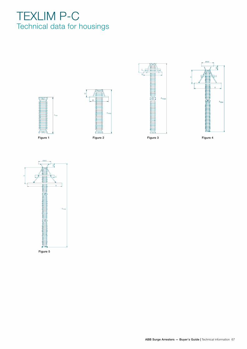
ABB Surge Arresters — Buyer´s Guide | Technical information 67
TEXLIM P-CTechnical data for housings
Figure 1 Figure 2 Figure 3 Figure 4
Figure 5 Figure 6

68 Technical information | ABB Surge Arresters — Buyer´s Guide
TEXLIM P-CAccessories
Line terminals
1HSA410 000-A
Aluminium
1HSA410 000-B
Aluminium flag with other
items in stainless steel
1HSA410 000-C
Aluminium
1HSA410 000-D
Stainless steel
Earth terminals
1HSA420 000-C
Stainless steel
1HSA420 000-D
Stainless steel
Drilling plans
Without insulating base
Aluminium
Insulating base
1HSA430000-V
M20 bolts for connection to structure are not supplied by ABB.
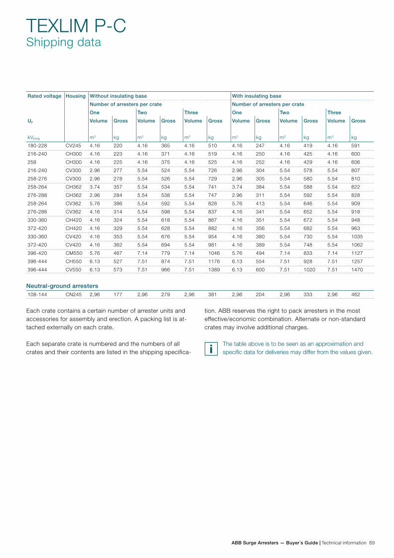
ABB Surge Arresters — Buyer´s Guide | Technical information 69
Rated voltage
Ur
kVrms
Housing Without insulating base With insulating base
Number of arresters per crate Number of arresters per crate
One Two Three One Two Three
Volume
m3
Gross
kg
Volume
m3
Gross
kg
Volume
m3
Gross
kg
Volume
m3
Gross
kg
Volume
m3
Gross
kg
Volume
m3
Gross
kg
180-228 CV245 4.16 220 4.16 365 4.16 510 4.16 247 4.16 419 4.16 591
216-240 CH300 4.16 223 4.16 371 4.16 519 4.16 250 4.16 425 4.16 600
258 CH300 4.16 225 4.16 375 4.16 525 4.16 252 4.16 429 4.16 606
216-240 CV300 2.96 277 5.54 524 5.54 726 2.96 304 5.54 578 5.54 807
258-276 CV300 2.96 278 5.54 526 5.54 729 2.96 305 5.54 580 5.54 810
258-264 CH362 3.74 357 5.54 534 5.54 741 3.74 384 5.54 588 5.54 822
276-288 CH362 2.96 284 5.54 538 5.54 747 2.96 311 5.54 592 5.54 828
258-264 CV362 5.76 386 5.54 592 5.54 828 5.76 413 5.54 646 5.54 909
276-288 CV362 4.16 314 5.54 598 5.54 837 4.16 341 5.54 652 5.54 918
330-360 CH420 4.16 324 5.54 618 5.54 867 4.16 351 5.54 672 5.54 948
372-420 CH420 4.16 329 5.54 628 5.54 882 4.16 356 5.54 682 5.54 963
330-360 CV420 4.16 353 5.54 676 5.54 954 4.16 380 5.54 730 5.54 1035
372-420 CV420 4.16 362 5.54 694 5.54 981 4.16 389 5.54 748 5.54 1062
396-420 CM550 5.76 467 7.14 779 7.14 1046 5.76 494 7.14 833 7.14 1127
396-444 CH550 6.13 527 7.51 874 7.51 1176 6.13 554 7.51 928 7.51 1257
396-444 CV550 6.13 573 7.51 966 7.51 1389 6.13 600 7.51 1020 7.51 1470
TEXLIM P-CShipping data
Each crate contains a certain number of arrester units and accessories for assembly and erection. A packing list is at-tached externally on each crate.
Each separate crate is numbered and the numbers of all crates and their contents are listed in the shipping specifica-
tion. ABB reserves the right to pack arresters in the most effective/economic combination. Alternate or non-standard crates may involve additional charges.
The table above is to be seen as an approximation and specific data for deliveries may differ from the values given.
108-144 CN245 2,96 177 2,96 279 2,96 381 2,96 204 2,96 333 2,96 462
Neutral-ground arresters
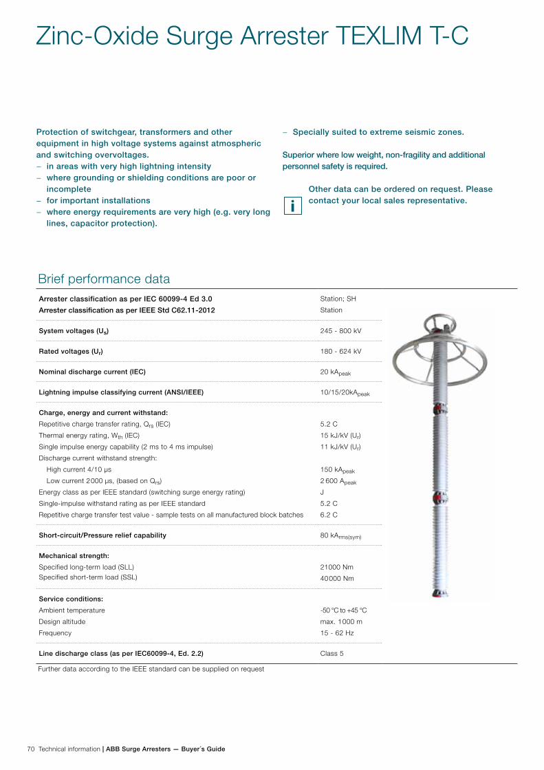
70 Technical information | ABB Surge Arresters — Buyer´s Guide
Zinc-Oxide Surge Arrester TEXLIM T-C
Protection of switchgear, transformers and other equipment in high voltage systems against atmospheric and switching overvoltages.
− in areas with very high lightning intensity − where grounding or shielding conditions are poor or
incomplete − for important installations − where energy requirements are very high (e.g. very long
lines, capacitor protection).
Brief performance dataArrester classification as per IEC 60099-4 Ed 3.0
Arrester classification as per IEEE Std C62.11-2012
Station; SH
Station
System voltages (Us) 245 - 800 kV
Rated voltages (Ur) 180 - 624 kV
Nominal discharge current (IEC) 20 kApeak
Lightning impulse classifying current (ANSI/IEEE) 10/15/20kApeak
Charge, energy and current withstand:
Repetitive charge transfer rating, Qrs (IEC)
Thermal energy rating, Wth (IEC)
Single impulse energy capability (2 ms to 4 ms impulse)
Discharge current withstand strength:
High current 4/10 µs
Low current 2 000 µs, (based on Qrs)
Energy class as per IEEE standard (switching surge energy rating)
Single-impulse withstand rating as per IEEE standard
Repetitive charge transfer test value - sample tests on all manufactured block batches
5.2 C
15 kJ/kV (Ur)
11 kJ/kV (Ur)
150 kApeak
2 600 Apeak
J
5.2 C
6.2 C
Short-circuit/Pressure relief capability 80 kArms(sym)
Mechanical strength:
Specified long-term load (SLL)Specified short-term load (SSL)
21000 Nm
40 000 Nm
Service conditions:
Ambient temperature
Design altitude
Frequency
-50 °C to +45 °C
max. 1 000 m
15 - 62 Hz
Line discharge class (as per IEC60099-4, Ed. 2.2) Class 5
Further data according to the IEEE standard can be supplied on request
− Specially suited to extreme seismic zones.
Superior where low weight, non-fragility and additional personnel safety is required.
Other data can be ordered on request. Please contact your local sales representative.

ABB Surge Arresters — Buyer´s Guide | Technical information 71
TEXLIM T-CGuaranteed protective data
Max. system voltage
Rated voltage
Max. continuous operating voltage 1)
TOV capability 2) Max. residual voltage with current wave
as per IEC
as per ANSI/IEEE
30/60 µs 8/20 µs
Us
kVrms
Ur
kVrms
Uc
kVrms
MCOV
kVrms
1 s
kVrms
10 s
kVrms
1 kA
kVpeak
2 kA
kVpeak
3 kA
kVpeak
5 kA
kVpeak
10 kA
kVpeak
20 kA
kVpeak
40 kA
kVpeak
245 180 144 144 199 189 346 356 363 381 396 428 466
192 154 154 212 201 369 380 387 406 423 457 497
198 156 160 218 208 381 392 399 419 436 471 512
210 156 170 232 220 404 415 423 444 462 499 543
216 156 174 238 227 415 427 435 457 476 514 559
219 156 177 242 230 421 433 441 463 482 521 567
222 156 179 245 233 427 439 447 469 489 528 574
228 156 180 252 239 438 451 459 482 502 542 590
300 216 173 174 238 227 415 427 435 457 476 514 559
228 182 182 252 239 438 451 459 482 502 542 590
240 191 191 265 252 461 475 484 507 528 571 621
258 191 209 285 271 496 510 520 545 568 614 667
264 191 212 291 277 508 522 532 558 581 628 683
276 191 220 305 290 531 546 556 583 608 656 714
362 258 206 209 285 271 496 510 520 545 568 614 667
264 211 212 291 277 508 522 532 558 581 628 683
276 221 221 305 290 531 546 556 583 608 656 714
288 230 230 318 302 554 569 580 609 634 685 745
420 330 264 267 364 347 634 652 665 697 726 785 854
336 267 272 371 353 646 664 677 710 740 799 869
342 267 277 378 359 657 676 689 723 753 813 885
360 267 291 398 378 692 712 725 761 792 856 931
372 267 301 411 391 715 735 749 786 819 884 962
378 267 306 418 397 726 747 761 799 832 899 978
381 267 308 421 400 732 753 767 805 839 906 985
390 267 315 431 410 750 771 786 824 858 927 1013
396 267 318 437 416 761 783 798 837 872 941 1029
420 267 336 464 441 807 830 846 888 924 998 1091
550 396 317 318 437 416 761 783 798 837 872 941 1029
420 336 336 464 441 807 830 846 888 924 998 1091
444 349 353 491 467 853 878 894 938 977 1060 1153
800 588 470 470 650 618 1134 1167 1189 1247 1299 1402 1525
612 490 490 676 643 1180 1214 1237 1298 1351 1459 1587
624 499 499 690 656 1203 1238 1261 1323 1378 1488 1618
1) The continuous operating voltages Uc (as per IEC) and MCOV (as per IEEE) differ only due to deviations in type test procedures. Uc has to be considered only when the actual system voltage is higher than the tabulated. Any arrester with Uc higher than or equal to the actual system voltage divided by √3 can be selected.
2) With prior duty equal to the thermal energy rating of 11 kJ/kV (Ur).
Arresters with lower or higher rated voltages may be available on request for special applications.
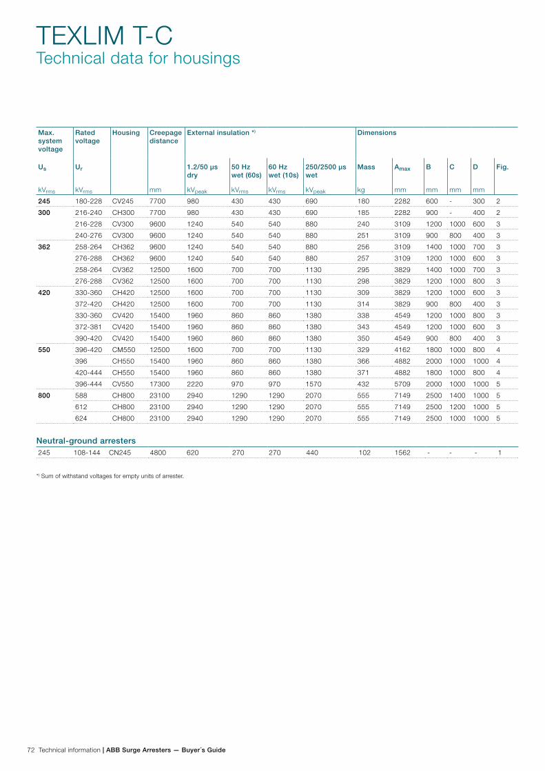
72 Technical information | ABB Surge Arresters — Buyer´s Guide
TEXLIM T-CTechnical data for housings
Max. system voltage
Rated voltage
Housing Creepage distance
mm
External insulation *) Dimensions
Us
kVrms
Ur
kVrms
1.2/50 µs dry
kVpeak
50 Hz wet (60s)
kVrms
60 Hz wet (10s)
kVrms
250/2500 µs wet
kVpeak
Mass
kg
Amax
mm
B
mm
C
mm
D
mm
Fig.
245 180-228 CV245 7700 980 430 430 690 180 2282 600 - 300 2
300 216-240 CH300 7700 980 430 430 690 185 2282 900 - 400 2
216-228 CV300 9600 1240 540 540 880 240 3109 1200 1000 600 3
240-276 CV300 9600 1240 540 540 880 251 3109 900 800 400 3
362 258-264 CH362 9600 1240 540 540 880 256 3109 1400 1000 700 3
276-288 CH362 9600 1240 540 540 880 257 3109 1200 1000 600 3
258-264 CV362 12500 1600 700 700 1130 295 3829 1400 1000 700 3
276-288 CV362 12500 1600 700 700 1130 298 3829 1200 1000 800 3
420 330-360 CH420 12500 1600 700 700 1130 309 3829 1200 1000 600 3
372-420 CH420 12500 1600 700 700 1130 314 3829 900 800 400 3
330-360 CV420 15400 1960 860 860 1380 338 4549 1200 1000 800 3
372-381 CV420 15400 1960 860 860 1380 343 4549 1200 1000 600 3
390-420 CV420 15400 1960 860 860 1380 350 4549 900 800 400 3
550 396-420 CM550 12500 1600 700 700 1130 329 4162 1800 1000 800 4
396 CH550 15400 1960 860 860 1380 366 4882 2000 1000 1000 4
420-444 CH550 15400 1960 860 860 1380 371 4882 1800 1000 800 4
396-444 CV550 17300 2220 970 970 1570 432 5709 2000 1000 1000 5
800 588 CH800 23100 2940 1290 1290 2070 555 7149 2500 1400 1000 5
612 CH800 23100 2940 1290 1290 2070 555 7149 2500 1200 1000 5
624 CH800 23100 2940 1290 1290 2070 555 7149 2500 1000 1000 5
245 108-144 CN245 4800 620 270 270 440 102 1562 - - - 1
Neutral-ground arresters
*) Sum of withstand voltages for empty units of arrester.

ABB Surge Arresters — Buyer´s Guide | Technical information 73
TEXLIM T-CTechnical data for housings
Figure 1 Figure 2 Figure 3 Figure 4
Figure 5 Figure 6
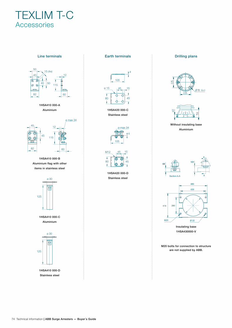
74 Technical information | ABB Surge Arresters — Buyer´s Guide
TEXLIM T-CAccessories
Line terminals
1HSA410 000-A
Aluminium
1HSA410 000-B
Aluminium flag with other
items in stainless steel
1HSA410 000-C
Aluminium
1HSA410 000-D
Stainless steel
Earth terminals
1HSA420 000-C
Stainless steel
1HSA420 000-D
Stainless steel
Drilling plans
Without insulating base
Aluminium
Insulating base
1HSA430000-V
M20 bolts for connection to structure are not supplied by ABB.
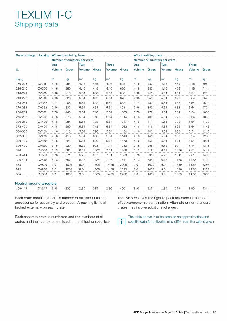
ABB Surge Arresters — Buyer´s Guide | Technical information 75
TEXLIM T-CShipping data
Each crate contains a certain number of arrester units and accessories for assembly and erection. A packing list is at-tached externally on each crate.
Each separate crate is numbered and the numbers of all crates and their contents are listed in the shipping specifica-
tion. ABB reserves the right to pack arresters in the most effective/economic combination. Alternate or non-standard crates may involve additional charges.
The table above is to be seen as an approximation and specific data for deliveries may differ from the values given.
Rated voltage
Ur
kVrms
Housing Without insulating base With insulating base
Number of arresters per crate Number of arresters per crate
One Two Three One Two Three
Volume
m3
Gross
kg
Volume
m3
Gross
kg
Volume
m3
Gross
kg
Volume
m3
Gross
kg
Volume
m3
Gross
kg
Volume
m3
Gross
kg
180-228 CV245 4.16 255 4.16 435 4.16 615 4.16 282 4.16 489 4.16 696
216-240 CH300 4.16 260 4.16 445 4.16 630 4.16 287 4.16 499 4.16 711
216-228 CV300 2.96 315 5.54 600 5.54 840 2.96 342 5.54 654 5.54 921
240-276 CV300 2.96 326 5.54 622 5.54 873 2.96 353 5.54 676 5.54 954
258-264 CH362 3.74 406 5.54 632 5.54 888 3.74 433 5.54 686 5.54 969
276-288 CH362 2.96 332 5.54 634 5.54 891 2.96 359 5.54 688 5.54 972
258-264 CV362 5.76 445 5.54 710 5.54 1005 5.76 472 5.54 764 5.54 1086
276-288 CV362 4.16 373 5.54 716 5.54 1014 4.16 400 5.54 770 5.54 1095
330-360 CH420 4.16 384 5.54 738 5.54 1047 4.16 411 5.54 792 5.54 1128
372-420 CH420 4.16 389 5.54 748 5.54 1062 4.16 416 5.54 802 5.54 1143
330-360 CV420 4.16 413 5.54 796 5.54 1134 4.16 440 5.54 850 5.54 1215
372-381 CV420 4.16 418 5.54 806 5.54 1149 4.16 445 5.54 860 5.54 1230
390-420 CV420 4.16 425 5.54 820 5.54 1170 4.16 452 5.54 874 5.54 1251
396-420 CM550 5.76 529 5.76 903 7.14 1232 5.76 556 5.76 957 7.14 1313
396 CH550 6.13 591 6.13 1002 7.51 1368 6.13 618 6.13 1056 7.51 1449
420-444 CH550 5.76 571 5.76 987 7.51 1358 5.76 598 5.76 1041 7.51 1439
396-444 CV550 6.13 657 6.13 1134 11.67 1641 6.13 684 6.13 1188 11.67 1722
588 CH800 9.0 1005 9.0 1605 14.55 2205 9.0 1032 9.0 1659 14.55 2286
612 CH800 9.0 1005 9.0 1605 14.55 2223 9.0 1032 9.0 1659 14.55 2304
624 CH800 9.0 1005 9.0 1605 14.55 2232 9.0 1032 9.0 1659 14.55 2313
108-144 CN245 2,96 200 2,96 325 2,96 450 2,96 227 2,96 379 2,96 531
Neutral-ground arresters
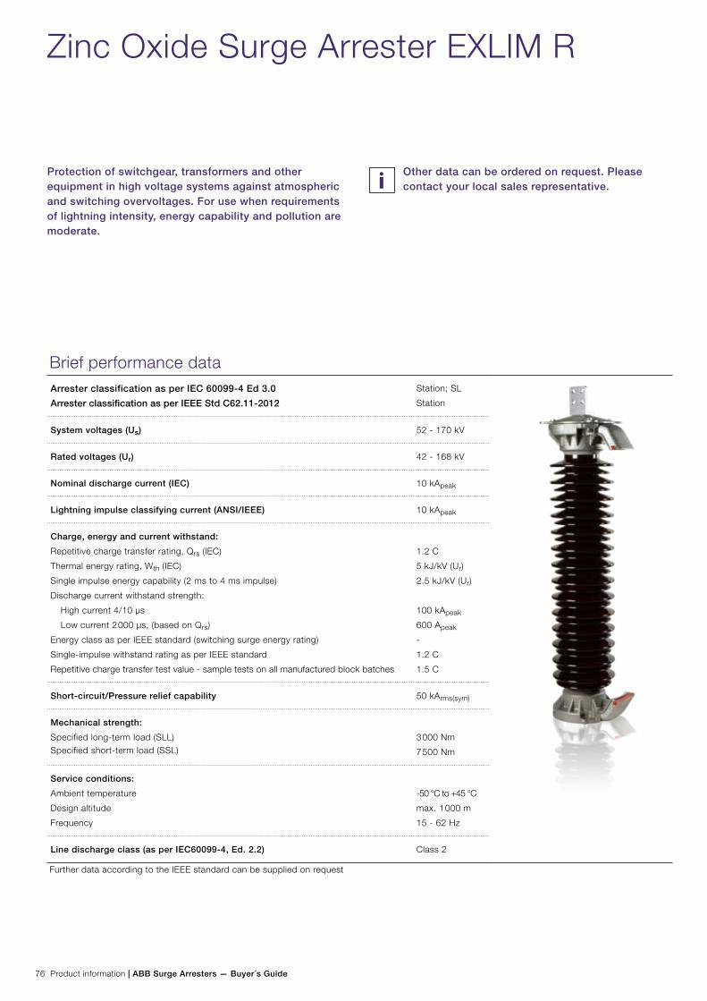
76 Product information | ABB Surge Arresters — Buyer´s Guide
Zinc Oxide Surge Arrester EXLIM R
Protection of switchgear, transformers and other equipment in high voltage systems against atmospheric and switching overvoltages. For use when requirements of lightning intensity, energy capability and pollution are moderate.
Brief performance dataArrester classification as per IEC 60099-4 Ed 3.0
Arrester classification as per IEEE Std C62.11-2012
Station; SL
Station
System voltages (Us) 52 - 170 kV
Rated voltages (Ur) 42 - 168 kV
Nominal discharge current (IEC) 10 kApeak
Lightning impulse classifying current (ANSI/IEEE) 10 kApeak
Charge, energy and current withstand:
Repetitive charge transfer rating, Qrs (IEC)
Thermal energy rating, Wth (IEC)
Single impulse energy capability (2 ms to 4 ms impulse)
Discharge current withstand strength:
High current 4/10 µs
Low current 2 000 µs, (based on Qrs)
Energy class as per IEEE standard (switching surge energy rating)
Single-impulse withstand rating as per IEEE standard
Repetitive charge transfer test value - sample tests on all manufactured block batches
1.2 C
5 kJ/kV (Ur)
2.5 kJ/kV (Ur)
100 kApeak
600 Apeak
-
1.2 C
1.5 C
Short-circuit/Pressure relief capability 50 kArms(sym)
Mechanical strength:
Specified long-term load (SLL)Specified short-term load (SSL)
3 000 Nm
7 500 Nm
Service conditions:
Ambient temperature
Design altitude
Frequency
-50 °C to +45 °C
max. 1 000 m
15 - 62 Hz
Line discharge class (as per IEC60099-4, Ed. 2.2) Class 2
Further data according to the IEEE standard can be supplied on request
Other data can be ordered on request. Please contact your local sales representative.
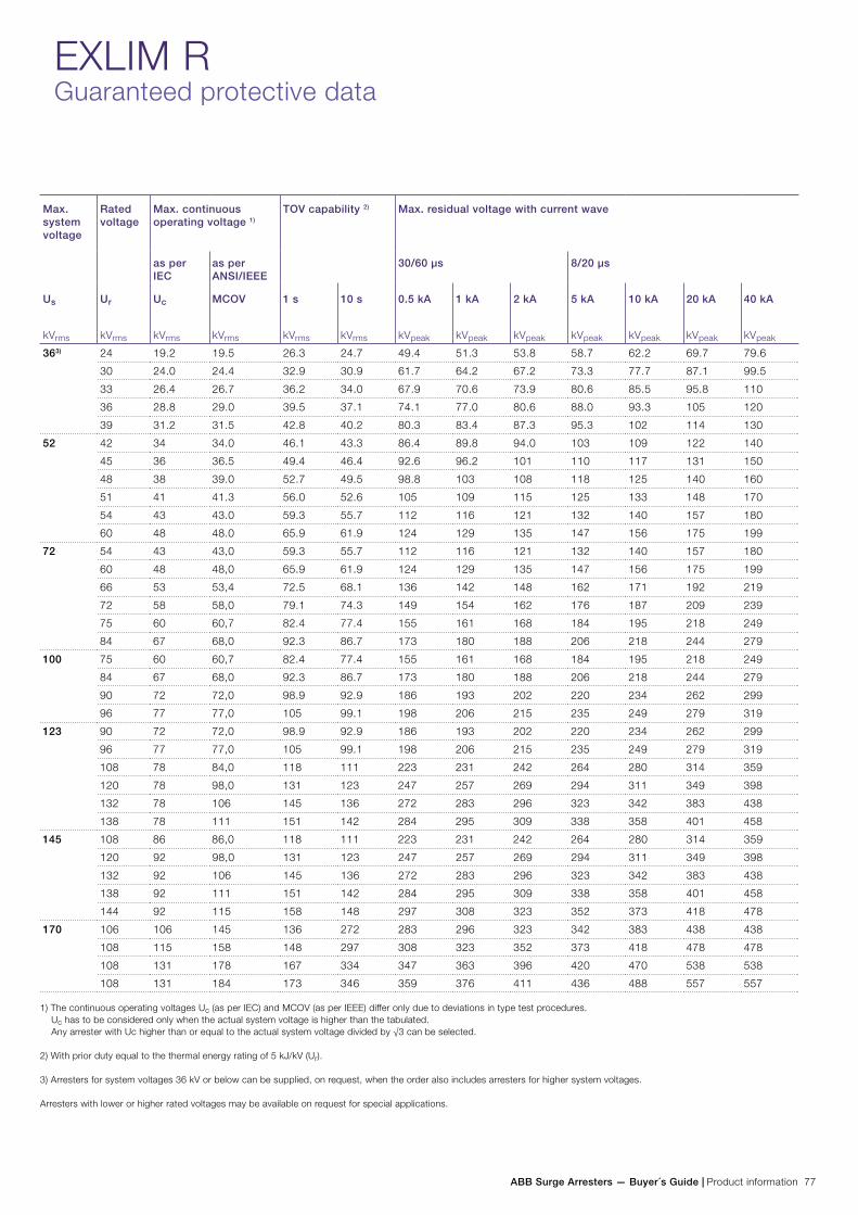
ABB Surge Arresters — Buyer´s Guide | Product information 77
EXLIM RGuaranteed protective data
Max. system voltage
Rated voltage
Max. continuous operating voltage 1)
TOV capability 2) Max. residual voltage with current wave
as per IEC
as per ANSI/IEEE
30/60 µs 8/20 µs
Us
kVrms
Ur
kVrms
Uc
kVrms
MCOV
kVrms
1 s
kVrms
10 s
kVrms
0.5 kA
kVpeak
1 kA
kVpeak
2 kA
kVpeak
5 kA
kVpeak
10 kA
kVpeak
20 kA
kVpeak
40 kA
kVpeak
363) 24 19.2 19.5 26.3 24.7 49.4 51.3 53.8 58.7 62.2 69.7 79.6
30 24.0 24.4 32.9 30.9 61.7 64.2 67.2 73.3 77.7 87.1 99.5
33 26.4 26.7 36.2 34.0 67.9 70.6 73.9 80.6 85.5 95.8 110
36 28.8 29.0 39.5 37.1 74.1 77.0 80.6 88.0 93.3 105 120
39 31.2 31.5 42.8 40.2 80.3 83.4 87.3 95.3 102 114 130
52 42 34 34.0 46.1 43.3 86.4 89.8 94.0 103 109 122 140
45 36 36.5 49.4 46.4 92.6 96.2 101 110 117 131 150
48 38 39.0 52.7 49.5 98.8 103 108 118 125 140 160
51 41 41.3 56.0 52.6 105 109 115 125 133 148 170
54 43 43.0 59.3 55.7 112 116 121 132 140 157 180
60 48 48.0 65.9 61.9 124 129 135 147 156 175 199
72 54 43 43,0 59.3 55.7 112 116 121 132 140 157 180
60 48 48,0 65.9 61.9 124 129 135 147 156 175 199
66 53 53,4 72.5 68.1 136 142 148 162 171 192 219
72 58 58,0 79.1 74.3 149 154 162 176 187 209 239
75 60 60,7 82.4 77.4 155 161 168 184 195 218 249
84 67 68,0 92.3 86.7 173 180 188 206 218 244 279
100 75 60 60,7 82.4 77.4 155 161 168 184 195 218 249
84 67 68,0 92.3 86.7 173 180 188 206 218 244 279
90 72 72,0 98.9 92.9 186 193 202 220 234 262 299
96 77 77,0 105 99.1 198 206 215 235 249 279 319
123 90 72 72,0 98.9 92.9 186 193 202 220 234 262 299
96 77 77,0 105 99.1 198 206 215 235 249 279 319
108 78 84,0 118 111 223 231 242 264 280 314 359
120 78 98,0 131 123 247 257 269 294 311 349 398
132 78 106 145 136 272 283 296 323 342 383 438
138 78 111 151 142 284 295 309 338 358 401 458
145 108 86 86,0 118 111 223 231 242 264 280 314 359
120 92 98,0 131 123 247 257 269 294 311 349 398
132 92 106 145 136 272 283 296 323 342 383 438
138 92 111 151 142 284 295 309 338 358 401 458
144 92 115 158 148 297 308 323 352 373 418 478
170 106 106 145 136 272 283 296 323 342 383 438 438
108 115 158 148 297 308 323 352 373 418 478 478
108 131 178 167 334 347 363 396 420 470 538 538
108 131 184 173 346 359 376 411 436 488 557 557
1) The continuous operating voltages Uc (as per IEC) and MCOV (as per IEEE) differ only due to deviations in type test procedures. Uc has to be considered only when the actual system voltage is higher than the tabulated. Any arrester with Uc higher than or equal to the actual system voltage divided by √3 can be selected.
2) With prior duty equal to the thermal energy rating of 5 kJ/kV (Ur).
3) Arresters for system voltages 36 kV or below can be supplied, on request, when the order also includes arresters for higher system voltages.
Arresters with lower or higher rated voltages may be available on request for special applications.
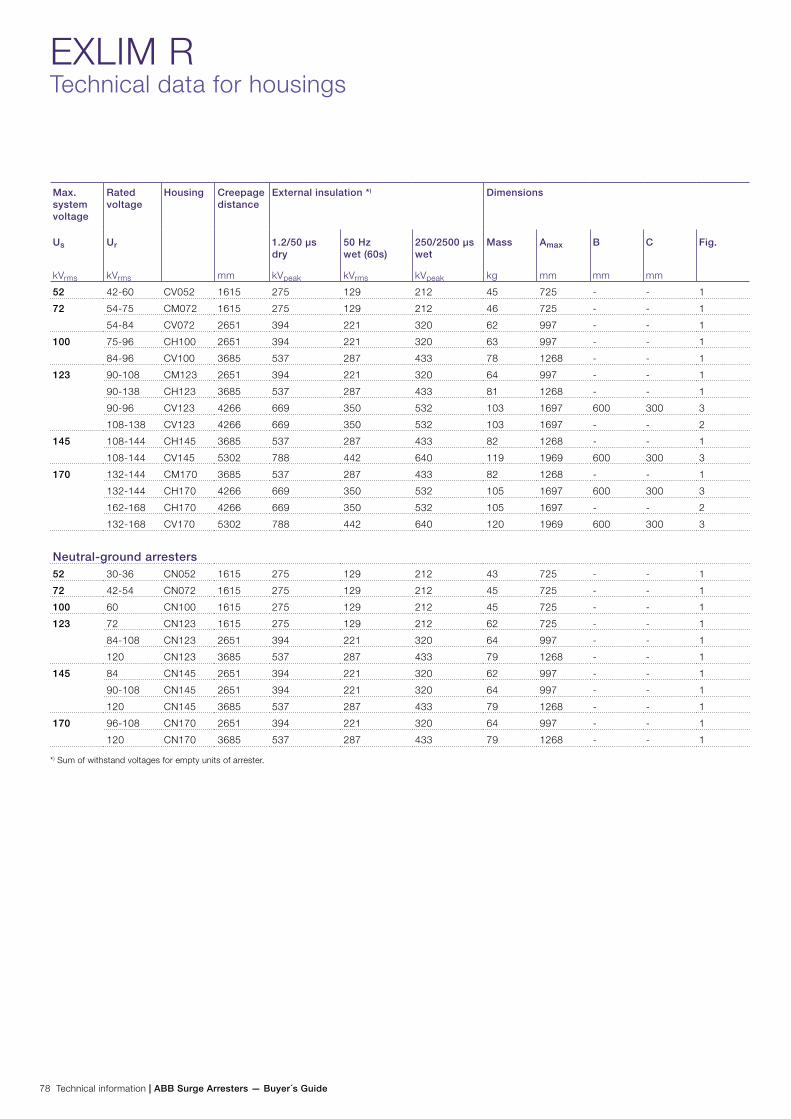
78 Technical information | ABB Surge Arresters — Buyer´s Guide
EXLIM RTechnical data for housings
Max. system voltage
Rated voltage
Housing Creepage distance
mm
External insulation *) Dimensions
Us
kVrms
Ur
kVrms
1.2/50 µs dry
kVpeak
50 Hz wet (60s)
kVrms
250/2500 µs wet
kVpeak
Mass
kg
Amax
mm
B
mm
C
mm
Fig.
52 42-60 CV052 1615 275 129 212 45 725 - - 1
72 54-75 CM072 1615 275 129 212 46 725 - - 1
54-84 CV072 2651 394 221 320 62 997 - - 1
100 75-96 CH100 2651 394 221 320 63 997 - - 1
84-96 CV100 3685 537 287 433 78 1268 - - 1
123 90-108 CM123 2651 394 221 320 64 997 - - 1
90-138 CH123 3685 537 287 433 81 1268 - - 1
90-96 CV123 4266 669 350 532 103 1697 600 300 3
108-138 CV123 4266 669 350 532 103 1697 - - 2
145 108-144 CH145 3685 537 287 433 82 1268 - - 1
108-144 CV145 5302 788 442 640 119 1969 600 300 3
170 132-144 CM170 3685 537 287 433 82 1268 - - 1
132-144 CH170 4266 669 350 532 105 1697 600 300 3
162-168 CH170 4266 669 350 532 105 1697 - - 2
132-168 CV170 5302 788 442 640 120 1969 600 300 3
Neutral-ground arresters52 30-36 CN052 1615 275 129 212 43 725 - - 1
72 42-54 CN072 1615 275 129 212 45 725 - - 1
100 60 CN100 1615 275 129 212 45 725 - - 1
123 72 CN123 1615 275 129 212 62 725 - - 1
84-108 CN123 2651 394 221 320 64 997 - - 1
120 CN123 3685 537 287 433 79 1268 - - 1
145 84 CN145 2651 394 221 320 62 997 - - 1
90-108 CN145 2651 394 221 320 64 997 - - 1
120 CN145 3685 537 287 433 79 1268 - - 1
170 96-108 CN170 2651 394 221 320 64 997 - - 1
120 CN170 3685 537 287 433 79 1268 - - 1
*) Sum of withstand voltages for empty units of arrester.
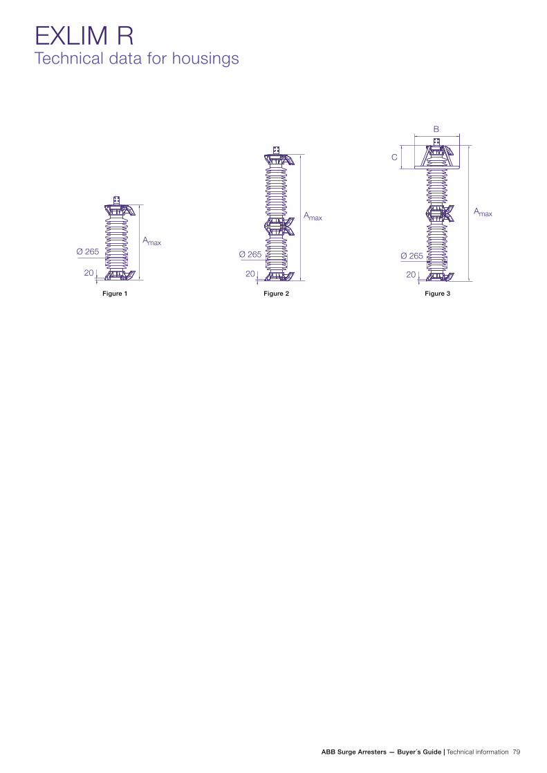
ABB Surge Arresters — Buyer´s Guide | Technical information 79
Figure 1 Figure 2 Figure 3
EXLIM RTechnical data for housings
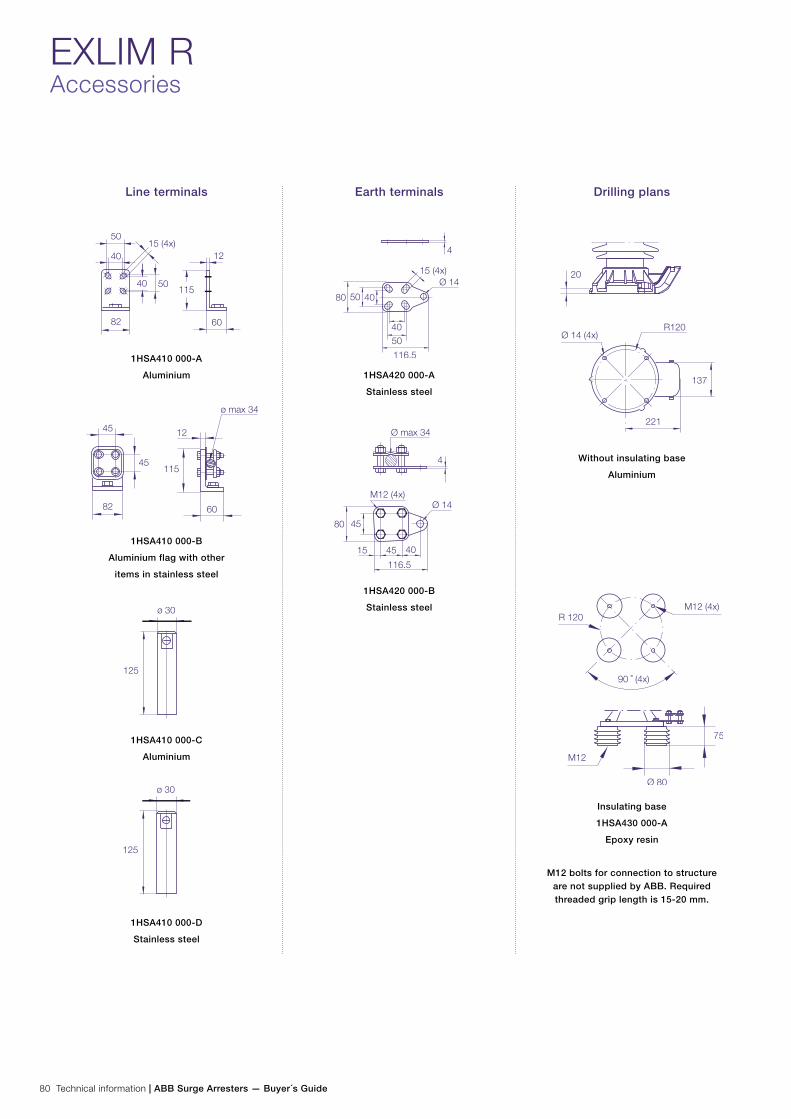
80 Technical information | ABB Surge Arresters — Buyer´s Guide
EXLIM RAccessories
Line terminals
1HSA410 000-A
Aluminium
1HSA410 000-B
Aluminium flag with other
items in stainless steel
1HSA410 000-C
Aluminium
1HSA410 000-D
Stainless steel
Earth terminals
1HSA420 000-A
Stainless steel
1HSA420 000-B
Stainless steel
Drilling plans
Without insulating base
Aluminium
Insulating base
1HSA430 000-A
Epoxy resin
M12 bolts for connection to structure are not supplied by ABB. Required threaded grip length is 15-20 mm.

ABB Surge Arresters — Buyer´s Guide | Technical information 81
Rated voltage Housing Number of arresters per crate
One Three Six
Ur
kVrms
Volume
m3
Gross
kg
Volume
m3
Gross
kg
Volume
m3
Gross
kg
24-39 CV036 0.3 74 0.5 171 1.0 337
42-60 CV052 0.3 76 0.5 177 1.0 349
54-75 CM072 0.3 77 0.5 180 1.0 355
54-84 CV072 0.3 93 0.7 228 1.4 451
75-96 CH100 0.3 94 0.7 231 1.4 457
84-96 CV100 0.4 115 0.8 276 1.7 547
90-108 CM123 0.3 92 0.7 234 1.4 463
90-138 CH123 0.4 116 0.8 279 1.7 553
90-138 CV123 0.7 131 1.4 367 - -
108-144 CH145 0.4 119 0.9 288 1.7 571
108-144 CV145 0.7 147 1.4 415 - -
132-144 CM170 0.4 119 0.9 288 1.7 571
132-168 CH170 0.7 133 1.4 373 - -
132-168 CV170 0.7 148 1.4 418 - -
Neutral-ground arresters30-36 CN052 0.3 75 0.5 175 1.0 340
42-54 CN072 0.3 80 0.5 180 1.0 350
60 CN100 0.3 80 0.5 180 1.0 350
72 CN123 0.3 80 0.5 180 1.0 355
84-108 CN123 0.3 95 0.7 235 1.4 465
120 CN123 0.4 115 0.8 280 1.7 555
84 CN145 0.3 95 0.7 230 1.4 455
90-108 CN145 0.3 95 0.7 235 1.4 465
120 CN145 0.4 115 0.8 280 1.7 555
96-108 CN170 0.3 95 0.7 235 1.4 465
120 CN170 0.4 115 0.8 280 1.7 555
EXLIM RShipping data
Each crate contains a certain number of arrester units and accessories for assembly and erection. A packing list is at-tached externally on each crate.
Each separate crate is numbered and the numbers of all crates and their contents are listed in the shipping specifica-
tion. ABB reserves the right to pack arresters in the most effective/economic combination. Alternate or non-standard crates may involve additional charges.
The table above is to be seen as an approximation and specific data for deliveries may differ from the values given.
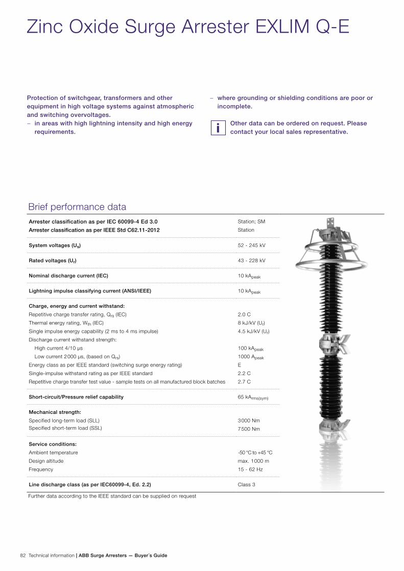
82 Technical information | ABB Surge Arresters — Buyer´s Guide
Zinc Oxide Surge Arrester EXLIM Q-E
Protection of switchgear, transformers and other equipment in high voltage systems against atmospheric and switching overvoltages.
− in areas with high lightning intensity and high energy requirements.
Brief performance dataArrester classification as per IEC 60099-4 Ed 3.0
Arrester classification as per IEEE Std C62.11-2012
Station; SM
Station
System voltages (Us) 52 - 245 kV
Rated voltages (Ur) 43 - 228 kV
Nominal discharge current (IEC) 10 kApeak
Lightning impulse classifying current (ANSI/IEEE) 10 kApeak
Charge, energy and current withstand:
Repetitive charge transfer rating, Qrs (IEC)
Thermal energy rating, Wth (IEC)
Single impulse energy capability (2 ms to 4 ms impulse)
Discharge current withstand strength:
High current 4/10 µs
Low current 2 000 µs, (based on Qrs)
Energy class as per IEEE standard (switching surge energy rating)
Single-impulse withstand rating as per IEEE standard
Repetitive charge transfer test value - sample tests on all manufactured block batches
2.0 C
8 kJ/kV (Ur)
4.5 kJ/kV (Ur)
100 kApeak
1000 Apeak
E
2.2 C
2.7 C
Short-circuit/Pressure relief capability 65 kArms(sym)
Mechanical strength:
Specified long-term load (SLL)Specified short-term load (SSL)
3 000 Nm
7 500 Nm
Service conditions:
Ambient temperature
Design altitude
Frequency
-50 °C to +45 °C
max. 1 000 m
15 - 62 Hz
Line discharge class (as per IEC60099-4, Ed. 2.2) Class 3
Further data according to the IEEE standard can be supplied on request
− where grounding or shielding conditions are poor or incomplete.
Other data can be ordered on request. Please contact your local sales representative.
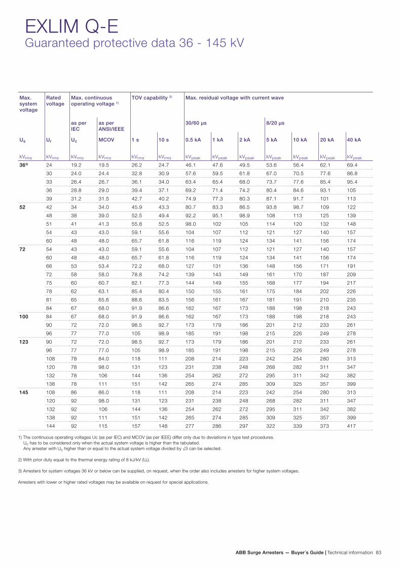
ABB Surge Arresters — Buyer´s Guide | Technical information 83
EXLIM Q-EGuaranteed protective data 36 - 145 kV
Max. system voltage
Rated voltage
Max. continuous operating voltage 1)
TOV capability 2) Max. residual voltage with current wave
as per IEC
as per ANSI/IEEE
30/60 µs 8/20 µs
Us
kVrms
Ur
kVrms
Uc
kVrms
MCOV
kVrms
1 s
kVrms
10 s
kVrms
0.5 kA
kVpeak
1 kA
kVpeak
2 kA
kVpeak
5 kA
kVpeak
10 kA
kVpeak
20 kA
kVpeak
40 kA
kVpeak
363) 24 19.2 19.5 26.2 24.7 46.1 47.6 49.5 53.6 56.4 62.1 69.4
30 24.0 24.4 32.8 30.9 57.6 59.5 61.8 67.0 70.5 77.6 86.8
33 26.4 26.7 36.1 34.0 63.4 65.4 68.0 73.7 77.6 85.4 95.4
36 28.8 29.0 39.4 37.1 69.2 71.4 74.2 80.4 84.6 93.1 105
39 31.2 31.5 42.7 40.2 74.9 77.3 80.3 87.1 91.7 101 113
52 42 34 34.0 45.9 43.3 80.7 83.3 86.5 93.8 98.7 109 122
48 38 39.0 52.5 49.4 92.2 95.1 98.9 108 113 125 139
51 41 41.3 55.8 52.5 98.0 102 105 114 120 132 148
54 43 43.0 59.1 55.6 104 107 112 121 127 140 157
60 48 48.0 65.7 61.8 116 119 124 134 141 156 174
72 54 43 43.0 59.1 55.6 104 107 112 121 127 140 157
60 48 48.0 65.7 61.8 116 119 124 134 141 156 174
66 53 53.4 72.2 68.0 127 131 136 148 156 171 191
72 58 58.0 78.8 74.2 139 143 149 161 170 187 209
75 60 60.7 82.1 77.3 144 149 155 168 177 194 217
78 62 63.1 85.4 80.4 150 155 161 175 184 202 226
81 65 65.6 88.6 83.5 156 161 167 181 191 210 235
84 67 68.0 91.9 86.6 162 167 173 188 198 218 243
100 84 67 68.0 91.9 86.6 162 167 173 188 198 218 243
90 72 72.0 98.5 92.7 173 179 186 201 212 233 261
96 77 77.0 105 98.9 185 191 198 215 226 249 278
123 90 72 72.0 98.5 92.7 173 179 186 201 212 233 261
96 77 77.0 105 98.9 185 191 198 215 226 249 278
108 78 84.0 118 111 208 214 223 242 254 280 313
120 78 98.0 131 123 231 238 248 268 282 311 347
132 78 106 144 136 254 262 272 295 311 342 382
138 78 111 151 142 265 274 285 309 325 357 399
145 108 86 86.0 118 111 208 214 223 242 254 280 313
120 92 98.0 131 123 231 238 248 268 282 311 347
132 92 106 144 136 254 262 272 295 311 342 382
138 92 111 151 142 265 274 285 309 325 357 399
144 92 115 157 148 277 286 297 322 339 373 417
1) The continuous operating voltages Uc (as per IEC) and MCOV (as per IEEE) differ only due to deviations in type test procedures. Uc has to be considered only when the actual system voltage is higher than the tabulated. Any arrester with Uc higher than or equal to the actual system voltage divided by √3 can be selected.
2) With prior duty equal to the thermal energy rating of 8 kJ/kV (Ur).
3) Arresters for system voltages 36 kV or below can be supplied, on request, when the order also includes arresters for higher system voltages.
Arresters with lower or higher rated voltages may be available on request for special applications.

84 Technical information | ABB Surge Arresters — Buyer´s Guide
EXLIM Q-EGuaranteed protective data 170 - 245 kV
Max. system voltage
Rated voltage
Max. continuous operating voltage 1)
TOV capability 2) Max. residual voltage with current wave
as per IEC
as per ANSI/IEEE
30/60 µs 8/20 µs
Us
kVrms
Ur
kVrms
Uc
kVrms
MCOV
kVrms
1 s
kVrms
10 s
kVrms
0.5 kA
kVpeak
1 kA
kVpeak
2 kA
kVpeak
5 kA
kVpeak
10 kA
kVpeak
20 kA
kVpeak
40 kA
kVpeak
170 132 106 106 144 136 254 262 272 295 311 342 382
144 108 115 157 148 277 286 297 322 339 373 417
162 108 131 177 167 312 321 334 362 381 419 469
168 108 131 183 173 323 333 346 376 395 435 486
245 180 144 144 197 185 346 357 371 402 423 466 521
192 154 154 210 197 369 381 396 429 452 497 555
198 156 160 216 204 381 393 408 443 466 512 573
210 156 170 229 216 404 417 433 469 494 543 608
216 156 175 236 222 415 428 445 483 508 559 625
219 156 177 239 225 421 434 451 489 515 567 634
222 156 179 243 228 427 440 458 496 522 574 642
228 156 180 249 235 438 452 470 510 536 590 660
1) The continuous operating voltages Uc (as per IEC) and MCOV (as per IEEE) differ only due to deviations in type test procedures. Uc has to be considered only when the actual system voltage is higher than the tabulated. Any arrester with Uc higher than or equal to the actual system voltage divided by √3 can be selected.
2) With prior duty equal to the thermal energy rating of 8 kJ/kV (Ur).
Arresters with lower or higher rated voltages may be available on request for special applications.

ABB Surge Arresters — Buyer´s Guide | Technical information 85
EXLIM Q-ETechnical data for housings
Max. system voltage
Rated voltage
Housing Creepage distance
mm
External insulation *) Dimensions
Um
kVrms
Ur
kVrms
1.2/50 µs dry
kVpeak
50 Hz wet (60s)
kVrms
60 Hz wet (10s)
kVrms
250/2500 µs wet
kVpeak
Mass
kg
Amax
mm
B
mm
C
mm
D
mm
Fig.
36 24-39 EV036 1615 275 129 133 n.a. 45 725 - - - 1
52 42-60 EV052 1615 275 129 133 n.a. 48 725 - - - 1
72 54-84 EV072 2651 394 221 203 n.a. 66 997 - - - 1
100 84-96 EH100 2651 394 221 203 n.a. 67 997 - - - 1
84-96 EV100 3685 537 287 261 n.a. 82 1268 - - - 1
123 90-108 EM123 2651 394 221 203 n.a. 69 997 - - - 1
90-138 EH123 3685 537 287 261 n.a. 88 1268 - - - 1
90-96 EV123 4266 669 350 336 n.a. 106 1697 600 - 300 3
108-138 EV123 4266 669 350 336 n.a. 110 1697 - - - 2
145 108-144 EH145 3685 537 287 261 n.a. 88 1268 - - - 1
108-120 EV145 5302 788 442 406 n.a. 124 1969 600 - 300 3
132-144 EV145 5302 788 442 406 n.a. 125 1969 - - - 2
170 132-144 EM170 3685 568 287 261 n.a. 88 1268 - - - 1
132 EH170 4266 669 350 336 n.a. 111 1697 600 - 300 3
144-168 EH170 4266 669 350 336 n.a. 113 1697 - - - 2
132-144 EV170 5302 788 442 406 n.a. 127 1969 600 - 300 3
150-168 EV170 5302 788 442 406 n.a. 128 1969 - - - 2
245 180-198 EH245 6336 931 508 464 753 151 2240 800 - 500 3
210-228 EH245 6336 931 508 464 753 153 2240 600 - 300 3
180-228 EV245 7953 1182 663 609 960 201 2941 1000 1400 700 4
Neutral-ground arresters 52 30-36 EN052 1615 275 129 133 n.a. 45 725 - - - 1
72 42-54 EN072 1615 275 129 133 n.a. 48 725 - - - 1
100 60 EN100 1615 275 129 133 n.a. 48 725 - - - 1
123 72-108 EN123 2651 394 221 203 n.a. 69 997 - - - 1
120 EN123 3685 537 287 261 n.a. 88 1268 - - - 1
145 84-108 EN145 2651 394 221 203 n.a. 69 997 - - - 1
120 EN145 3685 537 287 261 n.a. 88 1268 - - - 1
170 96-108 EN170 2651 394 221 203 n.a. 69 997 - - - 1
120 EN170 3685 537 287 261 n.a. 88 1268 - - - 1
245 108 EN245 2651 394 221 203 n.a. 69 997 - - - 1
120-144 EN245 3685 537 287 261 n.a. 88 1268 - - - 1
*) Sum of withstand voltages for empty units of arrester.
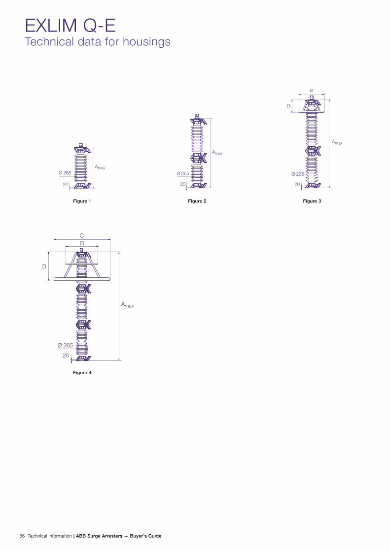
86 Technical information | ABB Surge Arresters — Buyer´s Guide
EXLIM Q-ETechnical data for housings
Figure 4
Figure 1 Figure 2 Figure 3
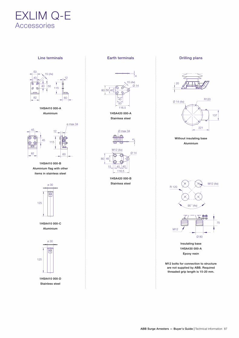
ABB Surge Arresters — Buyer´s Guide | Technical information 87
EXLIM Q-EAccessories
Line terminals
1HSA410 000-A
Aluminium
1HSA410 000-B
Aluminium flag with other
items in stainless steel
1HSA410 000-C
Aluminium
1HSA410 000-D
Stainless steel
Earth terminals
1HSA420 000-A
Stainless steel
1HSA420 000-B
Stainless steel
Drilling plans
Without insulating base
Aluminium
Insulating base
1HSA430 000-A
Epoxy resin
M12 bolts for connection to structure are not supplied by ABB. Required threaded grip length is 15-20 mm.
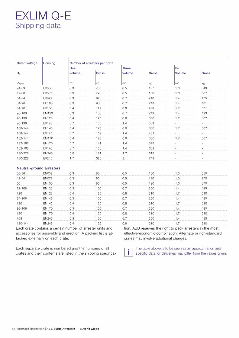
88 Technical information | ABB Surge Arresters — Buyer´s Guide
Rated voltage Housing Number of arresters per crate
One Three Six
Ur
kVrms
Volume
m3
Gross
kg
Volume
m3
Gross
kg
Volume
m3
Gross
kg
24-39 EV036 0.3 76 0.5 177 1.0 349
42-60 EV052 0.3 79 0.5 186 1.0 367
54-84 EV072 0.3 97 0.7 240 1.4 475
84-96 EH100 0.3 98 0.7 243 1.4 481
84-96 EV100 0.4 119 0.8 288 1.7 571
90-108 EM123 0.3 100 0.7 249 1.4 493
90-138 EH123 0.4 125 0.8 306 1.7 607
90-138 EV123 0.7 138 1.4 389 - -
108-144 EH145 0.4 125 0.9 306 1.7 607
108-144 EV145 0.7 152 1.4 431 - -
132-144 EM170 0.4 125 0.9 306 1.7 607
132-168 EH170 0.7 141 1.4 398 - -
132-168 EV170 0.7 156 1.4 662 - -
180-228 EH245 0.8 181 1.7 518 - -
180-228 EV245 1.7 320 3.1 743 - -
Neutral-ground arresters 30-36 EN052 0.3 80 0.5 180 1.0 350
42-54 EN072 0.3 80 0.5 190 1.0 370
60 EN100 0.3 80 0.5 190 1.0 370
72-108 EN123 0.3 100 0.7 250 1.4 495
120 EN123 0.4 125 0.8 310 1.7 610
84-108 EN145 0.3 100 0.7 250 1.4 495
120 EN145 0.4 125 0.8 310 1.7 610
96-108 EN170 0.3 100 0.7 250 1.4 495
120 EN170 0.4 125 0.8 310 1.7 610
108 EN245 0.3 100 0.7 250 1.4 495
120-144 EN245 0.4 125 0.8 310 1.7 610
EXLIM Q-EShipping data
Each crate contains a certain number of arrester units and accessories for assembly and erection. A packing list is at-tached externally on each crate.
Each separate crate is numbered and the numbers of all crates and their contents are listed in the shipping specifica-
tion. ABB reserves the right to pack arresters in the most effective/economic combination. Alternate or non-standard crates may involve additional charges.
The table above is to be seen as an approximation and specific data for deliveries may differ from the values given.

ABB Surge Arresters — Buyer´s Guide | Technical information 89
Zinc Oxide Surge Arrester EXLIM Q-D
Protection of switchgear, transformers and other equipment in high voltage systems against atmospheric and switching overvoltages.
− in areas with high lightning intensity and high energy requirements.
Brief performance dataArrester classification as per IEC 60099-4 Ed 3.0
Arrester classification as per IEEE Std C62.11-2012
Station; SM
Station
System voltages (Us) 170 - 420 kV
Rated voltages (Ur) 132 - 420 kV
Nominal discharge current (IEC) 10 kApeak
Lightning impulse classifying current (ANSI/IEEE) 10 kApeak
Charge, energy and current withstand:
Repetitive charge transfer rating, Qrs (IEC)
Thermal energy rating, Wth (IEC)
Single impulse energy capability (2 ms to 4 ms impulse)
Discharge current withstand strength:
High current 4/10 µs
Low current 2 000 µs, (based on Qrs)
Energy class as per IEEE standard (switching surge energy rating)
Single-impulse withstand rating as per IEEE standard
Repetitive charge transfer test value - sample tests on all manufactured block batches
2.0 C
8 kJ/kV (Ur)
4.5 kJ/kV (Ur)
100 kApeak
1000 Apeak
E
2.2 C
2.7 C
Short-circuit/Pressure relief capability 65 kArms(sym)
Mechanical strength:
Specified long-term load (SLL)Specified short-term load (SSL)
8000 Nm
20 000 Nm
Service conditions:
Ambient temperature
Design altitude
Frequency
-50 °C to +45 °C
max. 1 000 m
15 - 62 Hz
Line discharge class (as per IEC60099-4, Ed. 2.2) Class 3
Further data according to the IEEE standard can be supplied on request
− where grounding or shielding conditions are poor or incomplete.
Other data can be ordered on request. Please contact your local sales representative.
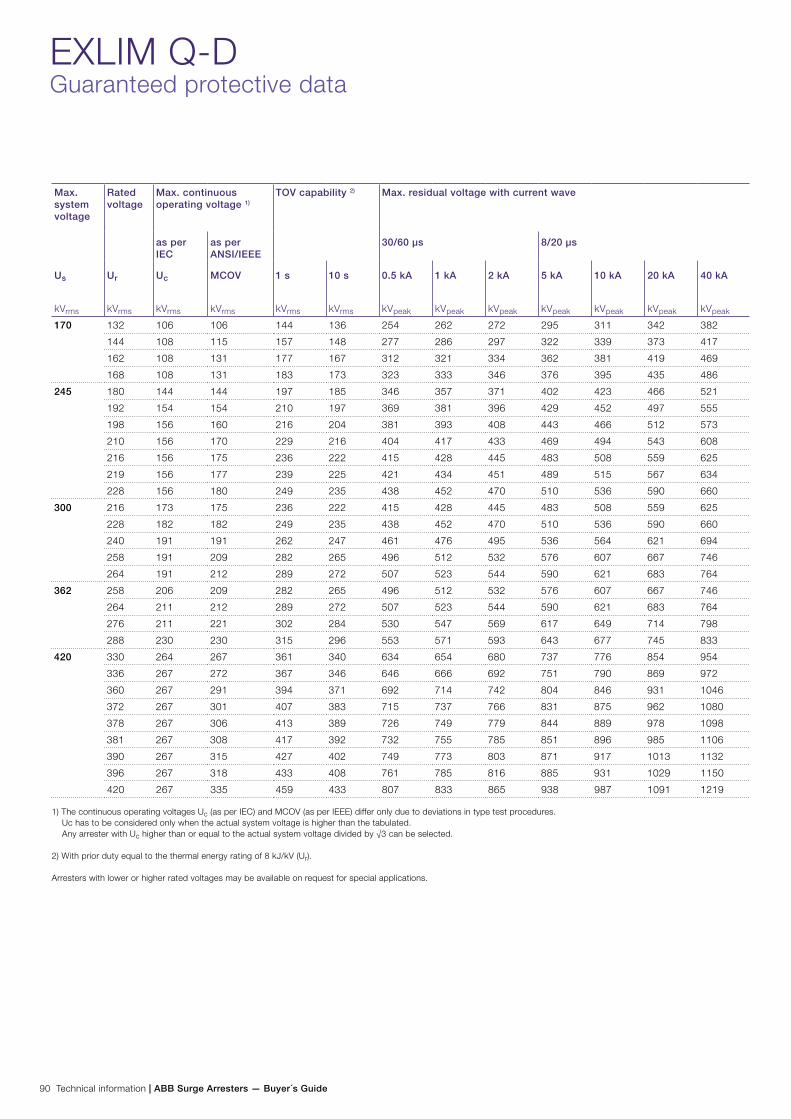
90 Technical information | ABB Surge Arresters — Buyer´s Guide
EXLIM Q-DGuaranteed protective data
Max. system voltage
Rated voltage
Max. continuous operating voltage 1)
TOV capability 2) Max. residual voltage with current wave
as per IEC
as per ANSI/IEEE
30/60 µs 8/20 µs
Us
kVrms
Ur
kVrms
Uc
kVrms
MCOV
kVrms
1 s
kVrms
10 s
kVrms
0.5 kA
kVpeak
1 kA
kVpeak
2 kA
kVpeak
5 kA
kVpeak
10 kA
kVpeak
20 kA
kVpeak
40 kA
kVpeak
170 132 106 106 144 136 254 262 272 295 311 342 382
144 108 115 157 148 277 286 297 322 339 373 417
162 108 131 177 167 312 321 334 362 381 419 469
168 108 131 183 173 323 333 346 376 395 435 486
245 180 144 144 197 185 346 357 371 402 423 466 521
192 154 154 210 197 369 381 396 429 452 497 555
198 156 160 216 204 381 393 408 443 466 512 573
210 156 170 229 216 404 417 433 469 494 543 608
216 156 175 236 222 415 428 445 483 508 559 625
219 156 177 239 225 421 434 451 489 515 567 634
228 156 180 249 235 438 452 470 510 536 590 660
300 216 173 175 236 222 415 428 445 483 508 559 625
228 182 182 249 235 438 452 470 510 536 590 660
240 191 191 262 247 461 476 495 536 564 621 694
258 191 209 282 265 496 512 532 576 607 667 746
264 191 212 289 272 507 523 544 590 621 683 764
362 258 206 209 282 265 496 512 532 576 607 667 746
264 211 212 289 272 507 523 544 590 621 683 764
276 211 221 302 284 530 547 569 617 649 714 798
288 230 230 315 296 553 571 593 643 677 745 833
420 330 264 267 361 340 634 654 680 737 776 854 954
336 267 272 367 346 646 666 692 751 790 869 972
360 267 291 394 371 692 714 742 804 846 931 1046
372 267 301 407 383 715 737 766 831 875 962 1080
378 267 306 413 389 726 749 779 844 889 978 1098
381 267 308 417 392 732 755 785 851 896 985 1106
390 267 315 427 402 749 773 803 871 917 1013 1132
396 267 318 433 408 761 785 816 885 931 1029 1150
420 267 335 459 433 807 833 865 938 987 1091 1219
1) The continuous operating voltages Uc (as per IEC) and MCOV (as per IEEE) differ only due to deviations in type test procedures. Uc has to be considered only when the actual system voltage is higher than the tabulated. Any arrester with Uc higher than or equal to the actual system voltage divided by √3 can be selected.
2) With prior duty equal to the thermal energy rating of 8 kJ/kV (Ur).
Arresters with lower or higher rated voltages may be available on request for special applications.
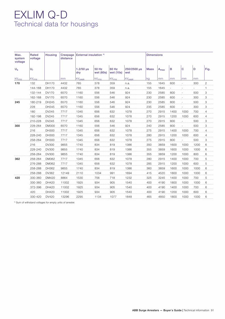
ABB Surge Arresters — Buyer´s Guide | Technical information 91
EXLIM Q-DTechnical data for housings
Max. system voltage
Rated voltage
Housing Creepage distance
mm
External insulation *) Dimensions
Us
kVrms
Ur
kVrms
1.2/50 µs dry
kVpeak
50 Hz wet (60s)
kVrms
60 Hz wet (10s)
kVrms
250/2500 µs wet
kVpeak
Mass
kg
Amax
mm
B
mm
C
mm
D
mm
Fig.
170 132 DH170 4432 765 378 359 n.a. 155 1645 600 - 300 2
144-168 DH170 4432 765 378 359 n.a. 155 1645 - - - 1
132-144 DV170 6570 1160 556 546 924 230 2585 800 - 500 3
162-168 DV170 6570 1160 556 546 924 230 2585 600 - 300 3
245 180-219 DH245 6570 1160 556 546 924 230 2585 800 - 500 3
228 DH245 6570 1160 556 546 924 235 2585 600 - 300 3
180 DV245 7717 1345 656 632 1078 270 2915 1400 1000 700 4
192-198 DV245 7717 1345 656 632 1078 270 2915 1200 1000 600 4
210-228 DV245 7717 1345 656 632 1078 270 2915 800 - 500 3
300 228-264 DM300 6570 1160 556 546 924 240 2585 800 - 500 3
216 DH300 7717 1345 656 632 1078 275 2915 1400 1000 700 4
228-240 DH300 7717 1345 656 632 1078 280 2915 1200 1000 600 4
258-264 DH300 7717 1345 656 632 1078 275 2915 800 - 500 3
216 DV300 9855 1740 834 819 1386 350 3859 1600 1000 1200 6
228-240 DV300 9855 1740 834 819 1386 355 3859 1600 1000 1000 6
258-264 DV300 9855 1740 834 819 1386 355 3859 1200 1000 800 6
362 258-264 DM362 7717 1345 656 632 1078 280 2915 1400 1000 700 5
276-288 DM362 7717 1345 656 632 1078 285 2915 1200 1000 600 5
258-288 DH362 9855 1740 834 819 1386 360 3859 1600 1000 1000 6
258-288 DV362 12149 2110 1034 991 1694 415 4520 1800 1000 1000 6
420 330-360 DM420 8864 1530 756 718 1232 325 3245 1400 1000 700 5
330-360 DH420 11002 1925 934 905 1540 400 4190 1800 1000 1000 6
372-396 DH420 11002 1925 934 905 1540 400 4190 1400 1000 700 6
420 DH420 11002 1925 934 905 1540 400 4190 1200 1000 600 6
330-420 DV420 13296 2295 1134 1077 1848 465 4850 1800 1000 1000 6
*) Sum of withstand voltages for empty units of arrester.
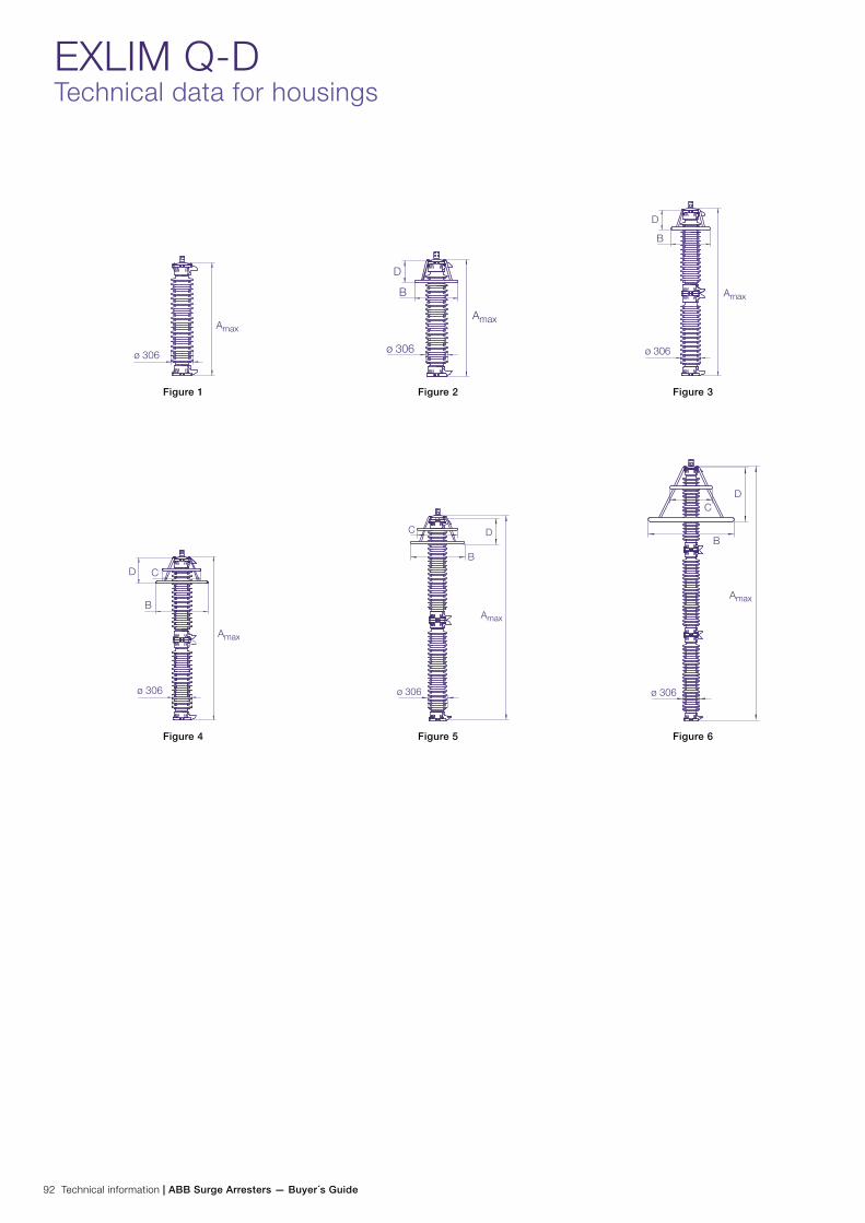
92 Technical information | ABB Surge Arresters — Buyer´s Guide
EXLIM Q-DTechnical data for housings
Figure 4 Figure 5 Figure 6
Figure 1 Figure 2 Figure 3
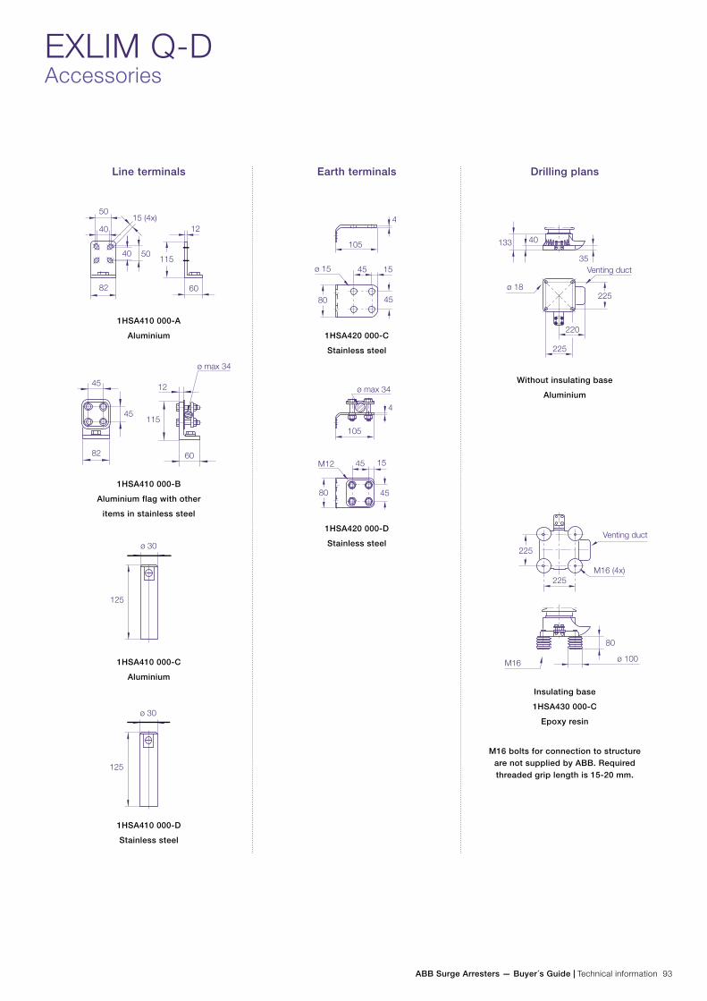
ABB Surge Arresters — Buyer´s Guide | Technical information 93
EXLIM Q-DAccessories
Line terminals
1HSA410 000-A
Aluminium
1HSA410 000-B
Aluminium flag with other
items in stainless steel
1HSA410 000-C
Aluminium
1HSA410 000-D
Stainless steel
Earth terminals
1HSA420 000-C
Stainless steel
1HSA420 000-D
Stainless steel
Drilling plans
Without insulating base
Aluminium
Insulating base
1HSA430 000-C
Epoxy resin
M16 bolts for connection to structure are not supplied by ABB. Required threaded grip length is 15-20 mm.
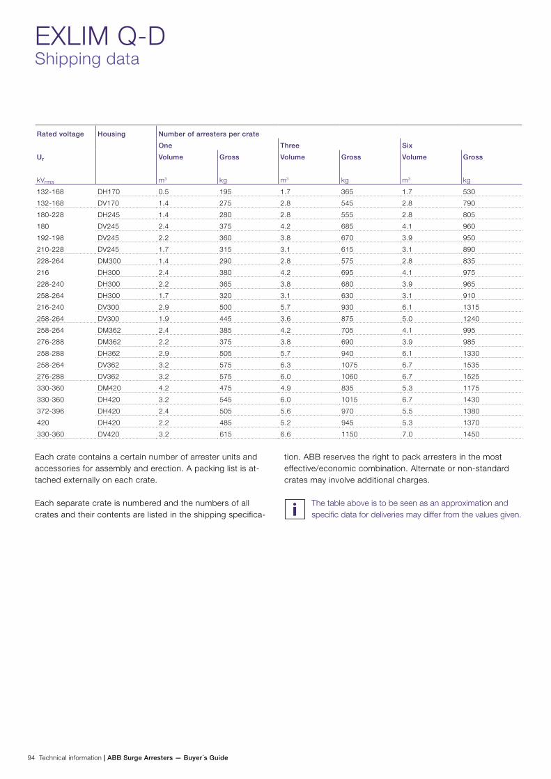
94 Technical information | ABB Surge Arresters — Buyer´s Guide
EXLIM Q-DShipping data
Rated voltage Housing Number of arresters per crate
One Three Six
Ur
kVrms
Volume
m3
Gross
kg
Volume
m3
Gross
kg
Volume
m3
Gross
kg
132-168 DH170 0.5 195 1.7 365 1.7 530
132-168 DV170 1.4 275 2.8 545 2.8 790
180-228 DH245 1.4 280 2.8 555 2.8 805
180 DV245 2.4 375 4.2 685 4.1 960
192-198 DV245 2.2 360 3.8 670 3.9 950
210-228 DV245 1.7 315 3.1 615 3.1 890
228-264 DM300 1.4 290 2.8 575 2.8 835
216 DH300 2.4 380 4.2 695 4.1 975
228-240 DH300 2.2 365 3.8 680 3.9 965
258-264 DH300 1.7 320 3.1 630 3.1 910
216-240 DV300 2.9 500 5.7 930 6.1 1315
258-264 DV300 1.9 445 3.6 875 5.0 1240
258-264 DM362 2.4 385 4.2 705 4.1 995
276-288 DM362 2.2 375 3.8 690 3.9 985
258-288 DH362 2.9 505 5.7 940 6.1 1330
258-264 DV362 3.2 575 6.3 1075 6.7 1535
276-288 DV362 3.2 575 6.0 1060 6.7 1525
330-360 DM420 4.2 475 4.9 835 5.3 1175
330-360 DH420 3.2 545 6.0 1015 6.7 1430
372-396 DH420 2.4 505 5.6 970 5.5 1380
420 DH420 2.2 485 5.2 945 5.3 1370
330-360 DV420 3.2 615 6.6 1150 7.0 1450
Each crate contains a certain number of arrester units and accessories for assembly and erection. A packing list is at-tached externally on each crate.
Each separate crate is numbered and the numbers of all crates and their contents are listed in the shipping specifica-
tion. ABB reserves the right to pack arresters in the most effective/economic combination. Alternate or non-standard crates may involve additional charges.
The table above is to be seen as an approximation and specific data for deliveries may differ from the values given.

ABB Surge Arresters — Buyer´s Guide | Technical information 95
Zinc Oxide Surge Arrester EXLIM P
Protection of switchgear, transformers and other equipment in high voltage systems against atmospheric and switching overvoltages.
− in areas with very high lightning intensity. − where grounding or shielding conditions
are poor or incomplete.
Brief performance dataArrester classification as per IEC 60099-4 Ed 3.0
Arrester classification as per IEEE Std C62.11-2012
Station; SH
Station
System voltages (Us) 52 - 550 kV
Rated voltages (Ur) 42 - 444 kV
Nominal discharge current (IEC) 20 kApeak
Lightning impulse classifying current (ANSI/IEEE) 10/15 kApeak
Charge, energy and current withstand:
Repetitive charge transfer rating, Qrs (IEC)
Thermal energy rating, Wth (IEC)
Single impulse energy capability (2 ms to 4 ms impulse)
Discharge current withstand strength:
High current 4/10 µs
Low current 2 000 µs, (based on Qrs)
Energy class as per IEEE standard (switching surge energy rating)
Single-impulse withstand rating as per IEEE standard
Repetitive charge transfer test value - sample tests on all manufactured block batches
3.2 C
11 kJ/kV (Ur)
7 kJ/kV (Ur)
100 kApeak
1600 Apeak
G
3.2 C
4.0 C
Short-circuit/Pressure relief capability 80 kArms(sym)
Mechanical strength:
Specified long-term load (SLL)Specified short-term load (SSL)
8000 Nm
20 000 Nm
Service conditions:
Ambient temperature
Design altitude
Frequency
-50 °C to +45 °C
max. 1 000 m
15 - 62 Hz
Line discharge class (as per IEC60099-4, Ed. 2.2) Class 4
Further data according to the IEEE standard can be supplied on request
− for important installations. − where energy requirements are very high (e.g. very long
lines, capacitor protection).
Other data can be ordered on request. Please contact your local sales representative.
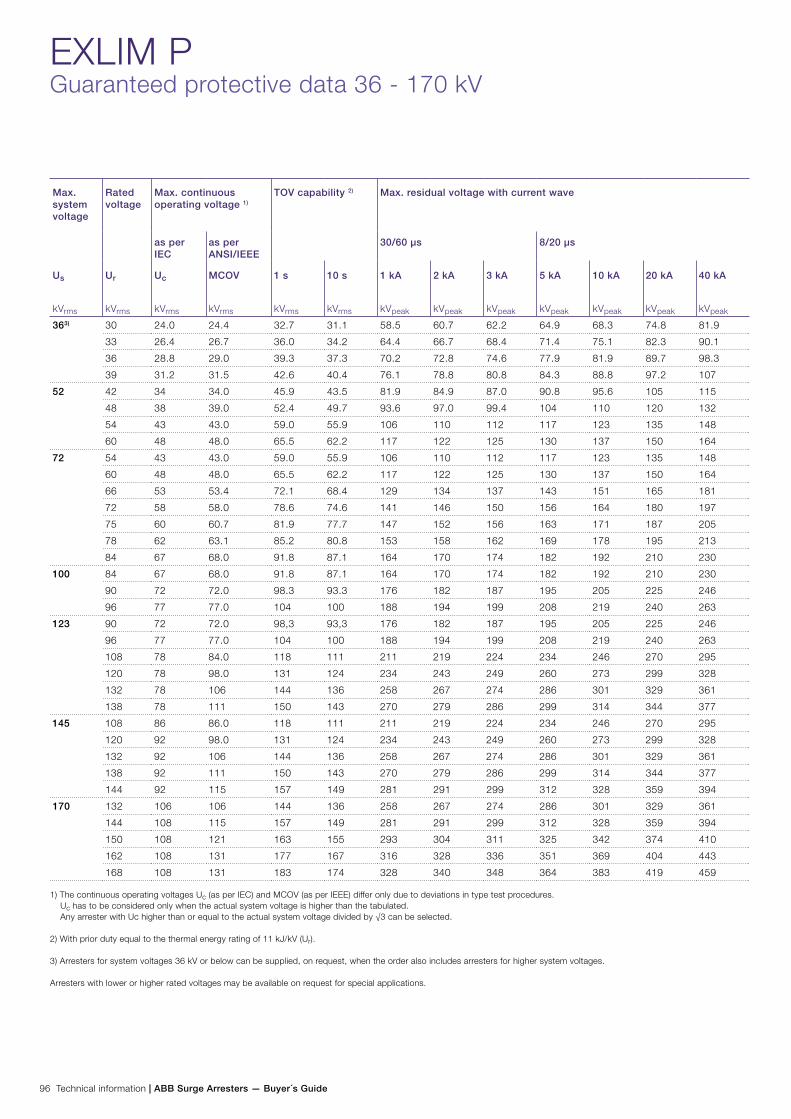
96 Technical information | ABB Surge Arresters — Buyer´s Guide
EXLIM PGuaranteed protective data 36 - 170 kV
Max. system voltage
Rated voltage
Max. continuous operating voltage 1)
TOV capability 2) Max. residual voltage with current wave
as per IEC
as per ANSI/IEEE
30/60 µs 8/20 µs
Us
kVrms
Ur
kVrms
Uc
kVrms
MCOV
kVrms
1 s
kVrms
10 s
kVrms
1 kA
kVpeak
2 kA
kVpeak
3 kA
kVpeak
5 kA
kVpeak
10 kA
kVpeak
20 kA
kVpeak
40 kA
kVpeak
363) 30 24.0 24.4 32.7 31.1 58.5 60.7 62.2 64.9 68.3 74.8 81.9
33 26.4 26.7 36.0 34.2 64.4 66.7 68.4 71.4 75.1 82.3 90.1
36 28.8 29.0 39.3 37.3 70.2 72.8 74.6 77.9 81.9 89.7 98.3
39 31.2 31.5 42.6 40.4 76.1 78.8 80.8 84.3 88.8 97.2 107
52 42 34 34.0 45.9 43.5 81.9 84.9 87.0 90.8 95.6 105 115
48 38 39.0 52.4 49.7 93.6 97.0 99.4 104 110 120 132
54 43 43.0 59.0 55.9 106 110 112 117 123 135 148
60 48 48.0 65.5 62.2 117 122 125 130 137 150 164
72 54 43 43.0 59.0 55.9 106 110 112 117 123 135 148
60 48 48.0 65.5 62.2 117 122 125 130 137 150 164
66 53 53.4 72.1 68.4 129 134 137 143 151 165 181
72 58 58.0 78.6 74.6 141 146 150 156 164 180 197
75 60 60.7 81.9 77.7 147 152 156 163 171 187 205
78 62 63.1 85.2 80.8 153 158 162 169 178 195 213
84 67 68.0 91.8 87.1 164 170 174 182 192 210 230
100 84 67 68.0 91.8 87.1 164 170 174 182 192 210 230
90 72 72.0 98.3 93.3 176 182 187 195 205 225 246
96 77 77.0 104 100 188 194 199 208 219 240 263
123 90 72 72.0 98,3 93,3 176 182 187 195 205 225 246
96 77 77.0 104 100 188 194 199 208 219 240 263
108 78 84.0 118 111 211 219 224 234 246 270 295
120 78 98.0 131 124 234 243 249 260 273 299 328
132 78 106 144 136 258 267 274 286 301 329 361
138 78 111 150 143 270 279 286 299 314 344 377
145 108 86 86.0 118 111 211 219 224 234 246 270 295
120 92 98.0 131 124 234 243 249 260 273 299 328
132 92 106 144 136 258 267 274 286 301 329 361
138 92 111 150 143 270 279 286 299 314 344 377
144 92 115 157 149 281 291 299 312 328 359 394
170 132 106 106 144 136 258 267 274 286 301 329 361
144 108 115 157 149 281 291 299 312 328 359 394
150 108 121 163 155 293 304 311 325 342 374 410
162 108 131 177 167 316 328 336 351 369 404 443
168 108 131 183 174 328 340 348 364 383 419 459
1) The continuous operating voltages Uc (as per IEC) and MCOV (as per IEEE) differ only due to deviations in type test procedures. Uc has to be considered only when the actual system voltage is higher than the tabulated. Any arrester with Uc higher than or equal to the actual system voltage divided by √3 can be selected.
2) With prior duty equal to the thermal energy rating of 11 kJ/kV (Ur).
3) Arresters for system voltages 36 kV or below can be supplied, on request, when the order also includes arresters for higher system voltages.
Arresters with lower or higher rated voltages may be available on request for special applications.
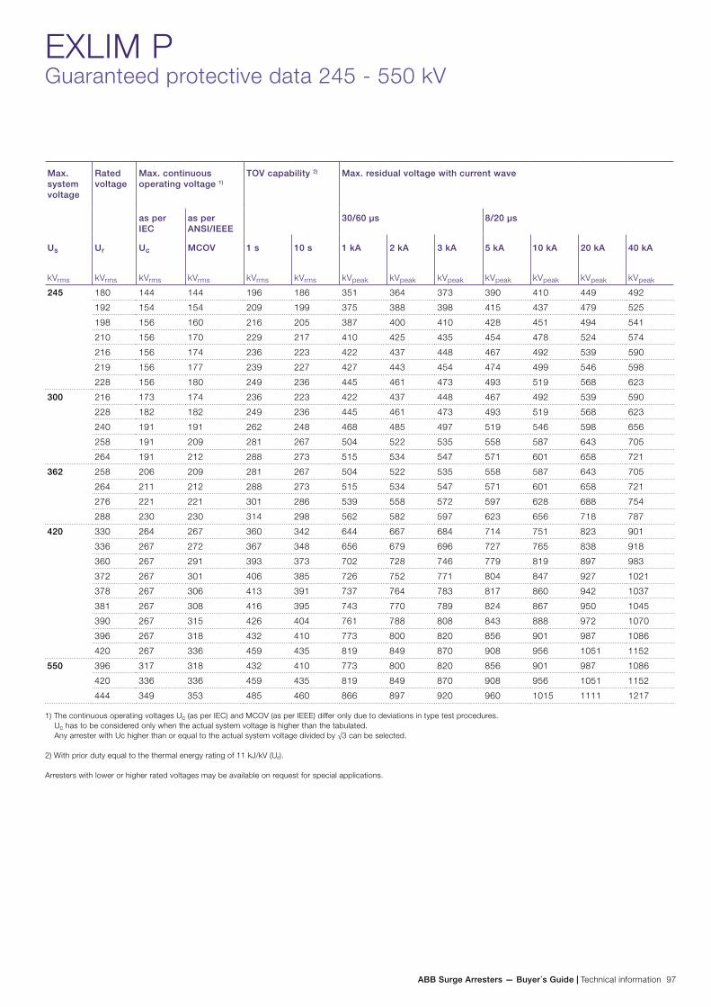
ABB Surge Arresters — Buyer´s Guide | Technical information 97
EXLIM PGuaranteed protective data 245 - 550 kV
Max. system voltage
Rated voltage
Max. continuous operating voltage 1)
TOV capability 2) Max. residual voltage with current wave
as per IEC
as per ANSI/IEEE
30/60 µs 8/20 µs
Us
kVrms
Ur
kVrms
Uc
kVrms
MCOV
kVrms
1 s
kVrms
10 s
kVrms
1 kA
kVpeak
2 kA
kVpeak
3 kA
kVpeak
5 kA
kVpeak
10 kA
kVpeak
20 kA
kVpeak
40 kA
kVpeak
245 180 144 144 196 186 351 364 373 390 410 449 492
192 154 154 209 199 375 388 398 415 437 479 525
198 156 160 216 205 387 400 410 428 451 494 541
210 156 170 229 217 410 425 435 454 478 524 574
216 156 174 236 223 422 437 448 467 492 539 590
219 156 177 239 227 427 443 454 474 499 546 598
228 156 180 249 236 445 461 473 493 519 568 623
300 216 173 174 236 223 422 437 448 467 492 539 590
228 182 182 249 236 445 461 473 493 519 568 623
240 191 191 262 248 468 485 497 519 546 598 656
258 191 209 281 267 504 522 535 558 587 643 705
264 191 212 288 273 515 534 547 571 601 658 721
362 258 206 209 281 267 504 522 535 558 587 643 705
264 211 212 288 273 515 534 547 571 601 658 721
276 221 221 301 286 539 558 572 597 628 688 754
288 230 230 314 298 562 582 597 623 656 718 787
420 330 264 267 360 342 644 667 684 714 751 823 901
336 267 272 367 348 656 679 696 727 765 838 918
360 267 291 393 373 702 728 746 779 819 897 983
372 267 301 406 385 726 752 771 804 847 927 1021
378 267 306 413 391 737 764 783 817 860 942 1037
381 267 308 416 395 743 770 789 824 867 950 1045
390 267 315 426 404 761 788 808 843 888 972 1070
396 267 318 432 410 773 800 820 856 901 987 1086
420 267 336 459 435 819 849 870 908 956 1051 1152
550 396 317 318 432 410 773 800 820 856 901 987 1086
420 336 336 459 435 819 849 870 908 956 1051 1152
444 349 353 485 460 866 897 920 960 1015 1111 1217
1) The continuous operating voltages Uc (as per IEC) and MCOV (as per IEEE) differ only due to deviations in type test procedures. Uc has to be considered only when the actual system voltage is higher than the tabulated. Any arrester with Uc higher than or equal to the actual system voltage divided by √3 can be selected.
2) With prior duty equal to the thermal energy rating of 11 kJ/kV (Ur).
Arresters with lower or higher rated voltages may be available on request for special applications.

98 Technical information | ABB Surge Arresters — Buyer´s Guide
EXLIM PTechnical data for housings 36 - 362 kV
Max. system voltage
Rated voltage
Housing Creepage distance
mm
External insulation Dimensions
Us
kVrms
Ur
kVrms
1.2/50 µs dry
kVpeak
50 Hz wet (60s)
kVrms
60 Hz wet (10s)
kVrms
250/2500 µs wet
kVpeak
Mass
kg
Amax
mm
B
mm
C
mm
D
mm
Fig.
36 30-39 GV036 1444 300 151 135 228 85 785 - - - 1
52 42-60 GH052 1444 300 151 135 228 90 785 - - - 1
42-60 GV052 3285 580 278 273 462 115 1315 - - - 1
72 54-84 GV072 3285 580 278 273 462 115 1315 - - - 1
100 84-96 GV100 3285 580 278 273 462 120 1315 - - - 1
123 90-138 GH123 3285 580 278 273 462 120 1315 - - - 1
90-138 GV123 4432 765 378 359 616 150 1645 - - - 1
145 108-138 GM145 3285 580 278 273 462 120 1315 - - - 1
108-120 GH145 4432 765 378 359 616 150 1645 - - - 1
132-144 GH145 4432 765 378 359 616 155 1645 - - - 1
108-144 GV145 4729 880 429 408 690 200 2060 - - - 2
170 132-168 GH170 4432 765 378 359 616 155 1645 - - - 1
132 GV170 6570 1160 556 546 924 230 2585 800 - 500 3
144-150 GV170 6570 1160 556 546 924 230 2585 600 - 300 3
162-168 GV170 6570 1160 556 546 924 230 2585 - - - 2
245 180-198 GH245 6570 1160 556 546 924 240 2585 800 - 500 4
210-228 GH245 6570 1160 556 546 924 240 2585 600 - 300 4
180 GV245 7717 1345 656 632 1078 275 2915 1200 1000 600 5
192-210 GV245 7717 1345 656 632 1078 270 2915 800 - 500 3
216-228 GV245 7717 1345 656 632 1078 270 2915 600 - 300 4
300 228-264 GM300 6570 1160 556 546 924 245 2585 800 - 500 4
216 GH300 7717 1345 656 632 1078 280 2915 1400 1000 700 5
228-264 GH300 7717 1345 656 632 1078 275 2915 800 - 500 4
216 GV300 9855 1740 834 819 1386 355 3860 1600 1000 1000 6
228 GV300 9855 1740 834 819 1386 355 3860 1400 1000 700 6
240 GV300 9855 1740 834 819 1386 355 3860 1200 1000 800 6
258-264 GV300 9855 1740 834 819 1386 355 3860 1200 1000 600 6
362 258 GM362 7717 1345 656 632 1078 285 2915 1400 1000 700 5
264-288 GM362 7717 1345 656 632 1078 285 2915 1200 1000 600 5
258-264 GH362 9855 1740 834 819 1386 360 3860 1600 1000 1000 6
276-288 GH362 9855 1740 834 819 1386 360 3860 1400 1000 700 6
258-288 GV362 12149 2110 1034 991 1694 420 4850 1600 1000 1200 6
*) Sum of withstand voltages for empty units of arrester.

ABB Surge Arresters — Buyer´s Guide | Technical information 99
EXLIM PTechnical data for housings 420 - 550 kV
Max. system voltage
Rated voltage
Housing Creepage distance
mm
External insulation *) Dimensions
Um
kVrms
Ur
kVrms
1.2/50 µs dry
kVpeak
50 Hz wet (60s)
kVrms
60 Hz wet (10s)
kVrms
250/2500 µs wet
kVpeak
Mass
kg
Amax
mm
B
mm
C
mm
D
mm
Fig.
420 330-360 GM420 8864 1530 756 718 1232 325 3245 1200 1000 600 5
330-336 GH420 11002 1925 934 905 1540 405 4190 1800 1000 1000 6
360-372 GH420 11002 1925 934 905 1540 405 4190 1400 1000 700 6
378-420 GH420 11002 1925 934 905 1540 405 4190 1200 1000 600 6
330-396 GV420 13296 2295 1134 1077 1848 460 4850 1600 1000 1000 6
420 GV420 13296 2295 1134 1077 1848 460 4850 1400 1000 700 6
550 396 GM550 11002 1925 934 905 1540 425 4500 2000 1000 1200 7
420 GM550 11002 1925 934 905 1540 420 4500 1800 1000 1000 7
444 GM550 11002 1925 934 905 1540 420 4500 1800 1000 800 7
396-444 GH550 14287 2505 1212 1178 2002 530 5763 2000 1000 1200 8
Neutral-ground arresters123 72-84 GN123 3285 580 278 273 462 115 1315 - - - 1
90-120 GN123 3285 580 278 273 462 120 1315 - - - 1
145 84 GN145 3285 580 278 273 462 115 1315 - - - 1
90-120 GN145 3285 580 278 273 462 120 1315 - - - 1
170 96-120 GN170 3285 580 278 273 462 120 1315 - - - 1
245 108-120 GN245 3285 580 278 273 462 120 1315 - - - 1
132 GN245 3285 580 278 273 462 125 1315 - - - 1
144 GN245 4432 765 378 359 616 155 1645 - - - 1
*) Sum of withstand voltages for empty units of arrester.

100 Technical information | ABB Surge Arresters — Buyer´s Guide
EXLIM PTechnical data for housings
Figure 1 Figure 2 Figure 3 Figure 4
Figure 5 Figure 6 Figure 7 Figure 8

ABB Surge Arresters — Buyer´s Guide | Technical information 101
EXLIM PAccessories
Line terminals
1HSA410 000-A
Aluminium
1HSA410 000-B
Aluminium flag with other
items in stainless steel
1HSA410 000-C
Aluminium
1HSA410 000-D
Stainless steel
Earth terminals
1HSA420 000-C
Stainless steel
1HSA420 000-D
Stainless steel
Drilling plans
Without insulating base
Aluminium
Insulating base
1HSA430 000-C
Epoxy resin
M16 bolts for connection to structure are not supplied by ABB. Required threaded grip length is 15-20 mm.
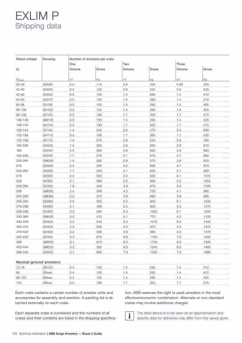
102 Technical information | ABB Surge Arresters — Buyer´s Guide
EXLIM PShipping data
Rated voltage Housing Number of arresters per crate
One Two Three
Ur
kVrms
Volume
m3
Gross
kg
Volume
m3
Gross
kg
Volume
m3
Gross
kg
30-39 GV036 0.4 115 0.9 225 0.90 320
42-60 GH052 0.4 120 0.9 235 0.9 335
42-60 GV052 0.5 150 1.4 285 1.4 410
54-84 GV072 0.5 150 1.4 285 1.4 410
84-96 GV100 0.5 155 1.4 295 1.4 425
90-138 GH123 0.5 155 1.4 295 1.4 425
90-138 GV123 0.5 190 1.7 355 1.7 515
108-138 GM145 0.5 155 1.4 295 1.4 425
108-144 GH145 0.5 190 1.7 355 1.7 515
108-144 GV145 1.4 245 2.3 470 2.3 690
132-168 GH170 0.5 195 1.7 365 1.7 530
132-168 GV170 1.4 275 2.8 545 2.8 780
180-228 GH245 1.4 285 2.8 565 2.8 810
180 GV245 2.2 365 3.8 665 3.9 945
192-228 GV245 1.7 315 3.1 615 3.1 895
228-264 GM300 1.4 290 2.8 575 2.8 825
216 GH300 2.4 385 4.2 690 4.1 975
228-264 GH300 1.7 320 3.1 630 3.1 905
216 GV300 2.5 500 5.2 930 6.1 1315
228 GV300 2.1 460 5.2 890 5.2 1255
240-264 GV300 1.9 445 4.9 875 5.0 1240
258 GM362 2.4 390 4.2 705 4.1 995
264-288 GM362 2.2 375 3.8 690 3.9 985
258-264 GH362 2.5 505 5.2 940 6.1 1330
276-288 GH362 2.1 465 5.2 900 5.2 1270
258-288 GV362 3.2 565 6.3 1050 6.7 1500
330-360 GM420 2.2 410 4.1 770 4.2 1105
330-336 GH420 3.2 545 6.0 1010 6.0 1440
360-372 GH420 2.4 505 5.5 970 5.5 1375
378-420 GH420 2.2 490 3.8 960 5.3 1370
330-420 GV420 3.2 610 6.6 1150 7.0 1645
396 GM550 5.1 615 6.5 1100 6.5 1520
420-444 GM550 3.2 565 6.0 1045 6.0 1485
396-444 GH550 5.1 805 7.9 1330 7.9 1860
Neutral-ground arresters72-78 GN123 0.4 150 1.4 285 1.4 410
84 GNxxx 0.4 150 1.4 285 1.4 410
90-132 GNxxx 0.4 155 1.4 295 1.4 425
144 GNxxx 0.5 190 1.7 355 1.7 515
Each crate contains a certain number of arrester units and accessories for assembly and erection. A packing list is at-tached externally on each crate.
Each separate crate is numbered and the numbers of all crates and their contents are listed in the shipping specifica-
tion. ABB reserves the right to pack arresters in the most effective/economic combination. Alternate or non-standard crates may involve additional charges.
The table above is to be seen as an approximation and specific data for deliveries may differ from the values given.
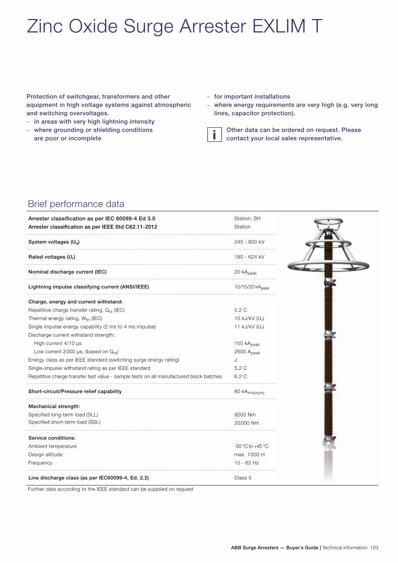
ABB Surge Arresters — Buyer´s Guide | Technical information 103
Zinc Oxide Surge Arrester EXLIM T
Protection of switchgear, transformers and other equipment in high voltage systems against atmospheric and switching overvoltages.
− in areas with very high lightning intensity − where grounding or shielding conditions
are poor or incomplete
Brief performance dataArrester classification as per IEC 60099-4 Ed 3.0
Arrester classification as per IEEE Std C62.11-2012
Station; SH
Station
System voltages (Us) 245 - 800 kV
Rated voltages (Ur) 180 - 624 kV
Nominal discharge current (IEC) 20 kApeak
Lightning impulse classifying current (ANSI/IEEE) 10/15/20 kApeak
Charge, energy and current withstand:
Repetitive charge transfer rating, Qrs (IEC)
Thermal energy rating, Wth (IEC)
Single impulse energy capability (2 ms to 4 ms impulse)
Discharge current withstand strength:
High current 4/10 µs
Low current 2 000 µs, (based on Qrs)
Energy class as per IEEE standard (switching surge energy rating)
Single-impulse withstand rating as per IEEE standard
Repetitive charge transfer test value - sample tests on all manufactured block batches
5.2 C
15 kJ/kV (Ur)
11 kJ/kV (Ur)
150 kApeak
2600 Apeak
J
5.2 C
6.2 C
Short-circuit/Pressure relief capability 80 kArms(sym)
Mechanical strength:
Specified long-term load (SLL)Specified short-term load (SSL)
8000 Nm
20 000 Nm
Service conditions:
Ambient temperature
Design altitude
Frequency
-50 °C to +45 °C
max. 1 000 m
15 - 62 Hz
Line discharge class (as per IEC60099-4, Ed. 2.2) Class 5
Further data according to the IEEE standard can be supplied on request
− for important installations − where energy requirements are very high (e.g. very long
lines, capacitor protection).
Other data can be ordered on request. Please contact your local sales representative.
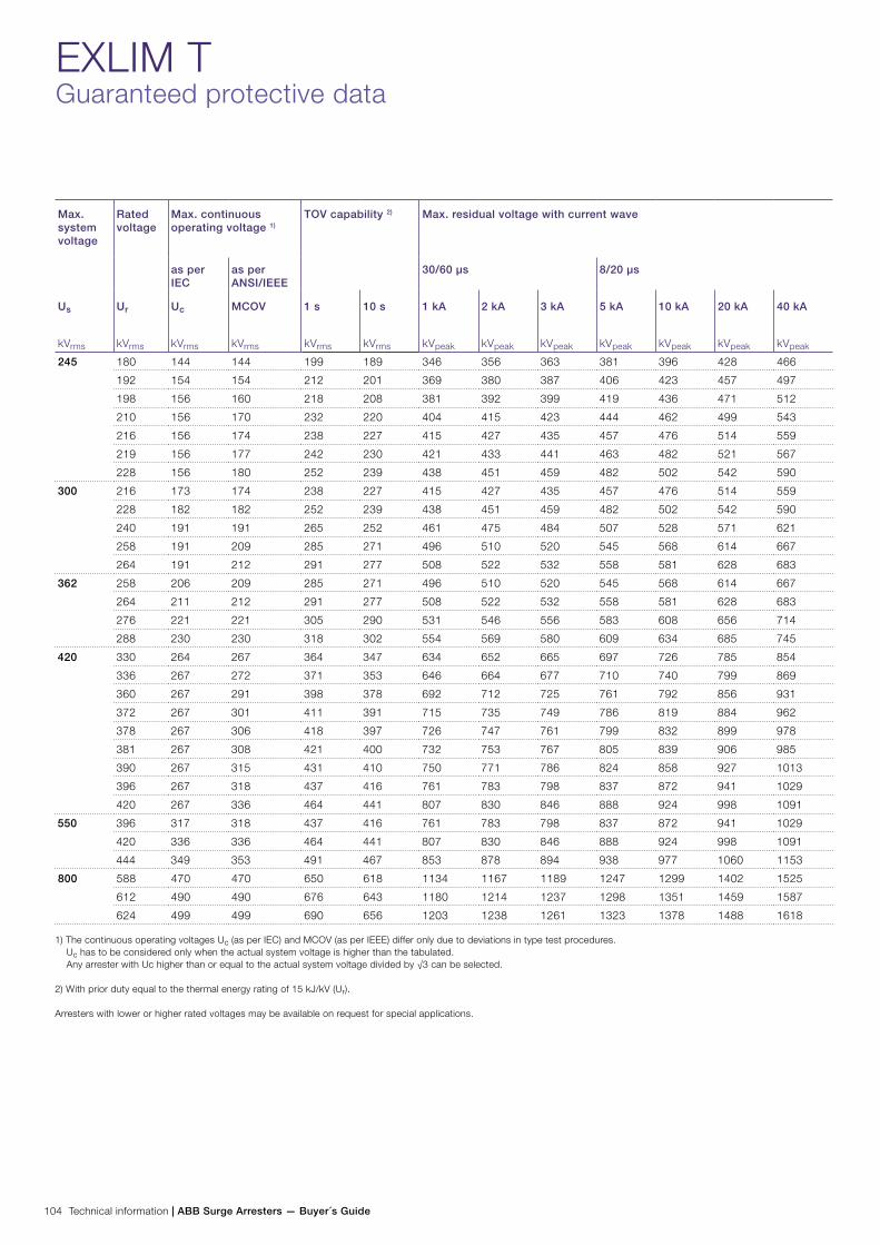
104 Technical information | ABB Surge Arresters — Buyer´s Guide
EXLIM TGuaranteed protective data
Max. system voltage
Rated voltage
Max. continuous operating voltage 1)
TOV capability 2) Max. residual voltage with current wave
as per IEC
as per ANSI/IEEE
30/60 µs 8/20 µs
Us
kVrms
Ur
kVrms
Uc
kVrms
MCOV
kVrms
1 s
kVrms
10 s
kVrms
1 kA
kVpeak
2 kA
kVpeak
3 kA
kVpeak
5 kA
kVpeak
10 kA
kVpeak
20 kA
kVpeak
40 kA
kVpeak
245 180 144 144 199 189 346 356 363 381 396 428 466
192 154 154 212 201 369 380 387 406 423 457 497
198 156 160 218 208 381 392 399 419 436 471 512
210 156 170 232 220 404 415 423 444 462 499 543
216 156 174 238 227 415 427 435 457 476 514 559
219 156 177 242 230 421 433 441 463 482 521 567
228 156 180 252 239 438 451 459 482 502 542 590
300 216 173 174 238 227 415 427 435 457 476 514 559
228 182 182 252 239 438 451 459 482 502 542 590
240 191 191 265 252 461 475 484 507 528 571 621
258 191 209 285 271 496 510 520 545 568 614 667
264 191 212 291 277 508 522 532 558 581 628 683
362 258 206 209 285 271 496 510 520 545 568 614 667
264 211 212 291 277 508 522 532 558 581 628 683
276 221 221 305 290 531 546 556 583 608 656 714
288 230 230 318 302 554 569 580 609 634 685 745
420 330 264 267 364 347 634 652 665 697 726 785 854
336 267 272 371 353 646 664 677 710 740 799 869
360 267 291 398 378 692 712 725 761 792 856 931
372 267 301 411 391 715 735 749 786 819 884 962
378 267 306 418 397 726 747 761 799 832 899 978
381 267 308 421 400 732 753 767 805 839 906 985
390 267 315 431 410 750 771 786 824 858 927 1013
396 267 318 437 416 761 783 798 837 872 941 1029
420 267 336 464 441 807 830 846 888 924 998 1091
550 396 317 318 437 416 761 783 798 837 872 941 1029
420 336 336 464 441 807 830 846 888 924 998 1091
444 349 353 491 467 853 878 894 938 977 1060 1153
800 588 470 470 650 618 1134 1167 1189 1247 1299 1402 1525
612 490 490 676 643 1180 1214 1237 1298 1351 1459 1587
624 499 499 690 656 1203 1238 1261 1323 1378 1488 1618
1) The continuous operating voltages Uc (as per IEC) and MCOV (as per IEEE) differ only due to deviations in type test procedures. Uc has to be considered only when the actual system voltage is higher than the tabulated. Any arrester with Uc higher than or equal to the actual system voltage divided by √3 can be selected.
2) With prior duty equal to the thermal energy rating of 15 kJ/kV (Ur).
Arresters with lower or higher rated voltages may be available on request for special applications.
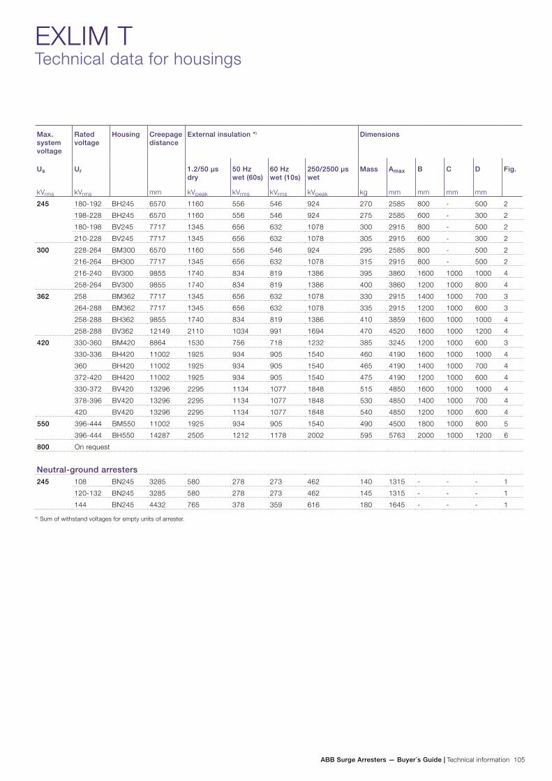
ABB Surge Arresters — Buyer´s Guide | Technical information 105
EXLIM TTechnical data for housings
Max. system voltage
Rated voltage
Housing Creepage distance
mm
External insulation *) Dimensions
Us
kVrms
Ur
kVrms
1.2/50 µs dry
kVpeak
50 Hz wet (60s)
kVrms
60 Hz wet (10s)
kVrms
250/2500 µs wet
kVpeak
Mass
kg
Amax
mm
B
mm
C
mm
D
mm
Fig.
245 180-192 BH245 6570 1160 556 546 924 270 2585 800 - 500 2
198-228 BH245 6570 1160 556 546 924 275 2585 600 - 300 2
180-198 BV245 7717 1345 656 632 1078 300 2915 800 - 500 2
210-228 BV245 7717 1345 656 632 1078 305 2915 600 - 300 2
300 228-264 BM300 6570 1160 556 546 924 295 2585 800 - 500 2
216-264 BH300 7717 1345 656 632 1078 315 2915 800 - 500 2
216-240 BV300 9855 1740 834 819 1386 395 3860 1600 1000 1000 4
258-264 BV300 9855 1740 834 819 1386 400 3860 1200 1000 800 4
362 258 BM362 7717 1345 656 632 1078 330 2915 1400 1000 700 3
264-288 BM362 7717 1345 656 632 1078 335 2915 1200 1000 600 3
258-288 BH362 9855 1740 834 819 1386 410 3859 1600 1000 1000 4
258-288 BV362 12149 2110 1034 991 1694 470 4520 1600 1000 1200 4
420 330-360 BM420 8864 1530 756 718 1232 385 3245 1200 1000 600 3
330-336 BH420 11002 1925 934 905 1540 460 4190 1600 1000 1000 4
360 BH420 11002 1925 934 905 1540 465 4190 1400 1000 700 4
372-420 BH420 11002 1925 934 905 1540 475 4190 1200 1000 600 4
330-372 BV420 13296 2295 1134 1077 1848 515 4850 1600 1000 1000 4
378-396 BV420 13296 2295 1134 1077 1848 530 4850 1400 1000 700 4
420 BV420 13296 2295 1134 1077 1848 540 4850 1200 1000 600 4
550 396-444 BM550 11002 1925 934 905 1540 490 4500 1800 1000 800 5
396-444 BH550 14287 2505 1212 1178 2002 595 5763 2000 1000 1200 6
800 On request
Neutral-ground arresters245 108 BN245 3285 580 278 273 462 140 1315 - - - 1
120-132 BN245 3285 580 278 273 462 145 1315 - - - 1
144 BN245 4432 765 378 359 616 180 1645 - - - 1
*) Sum of withstand voltages for empty units of arrester.
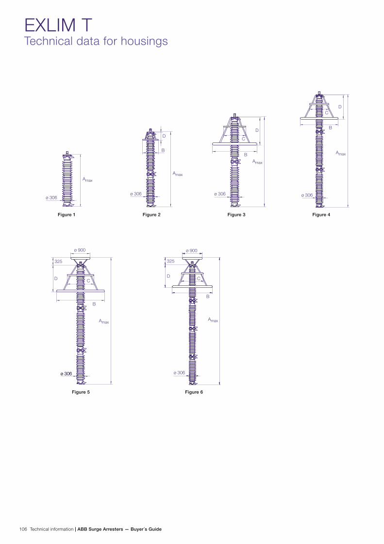
106 Technical information | ABB Surge Arresters — Buyer´s Guide
EXLIM TTechnical data for housings
Figure 1 Figure 2 Figure 3 Figure 4
Figure 5 Figure 6
ø 306
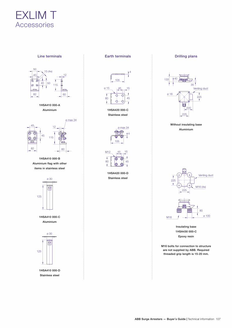
ABB Surge Arresters — Buyer´s Guide | Technical information 107
EXLIM TAccessories
Line terminals
1HSA410 000-A
Aluminium
1HSA410 000-B
Aluminium flag with other
items in stainless steel
1HSA410 000-C
Aluminium
1HSA410 000-D
Stainless steel
Earth terminals
1HSA420 000-C
Stainless steel
1HSA420 000-D
Stainless steel
Drilling plans
Without insulating base
Aluminium
Insulating base
1HSA430 000-C
Epoxy resin
M16 bolts for connection to structure are not supplied by ABB. Required threaded grip length is 15-20 mm.

108 Technical information | ABB Surge Arresters — Buyer´s Guide
EXLIM TShipping data
Rated voltage Housing Number of arresters per crate
One Two Three
Ur
kVrms
Volume
m3
Gross
kg
Volume
m3
Gross
kg
Volume
m3
Gross
kg
180-228 BH245 1.4 320 2.8 635 2.8 925
180-228 BV245 1.7 360 3.1 705 3.1 1025
228-264 BM300 1.4 340 2.8 675 2.8 985
216 BH300 2.2 410 3.8 755 3.8 1080
228-264 BH300 1.7 375 3.1 730 3.1 1060
216-240 BV300 2.9 540 5.7 1010 6.1 1435
258-264 BV300 1.9 490 3.5 965 5.0 1375
258 BM362 2.4 435 4.2 800 4.2 1140
264-288 BM362 2.2 430 3.8 800 3.8 1145
258-288 BH362 2.9 555 5.7 1040 6.1 1480
258-288 BV362 3.2 620 6.3 1150 6.3 1500
330-360 BM420 2.2 485 4.1 900 3.4 1300
330-336 BH420 3.2 605 6.3 1130 6.3 1620
360 BH420 2.4 570 4.2 1100 4.2 1570
372-420 BH420 2.2 575 3.8 1120 3.8 1610
330-336 BV420 3.2 665 6.6 1255 7.0 1805
360-378 BV420 3.2 680 6.6 1280 7.0 1840
381-396 BV420 2.4 640 6.1 1240 6.1 1780
420 BV420 2.2 635 5.8 1225 5.9 1795
396-420 BM550 5.1 710 6.5 1270 6.5 1795
444 BM550 3.2 665 6.0 1215 6.0 1745
396-444 BH550 5.1 805 7.9 1500 7.9 2105
Neutral-ground arresters108-132 BN245 0.5 180 1.4 345 1.4 500
144 BN245 0.5 220 1.7 415 1.7 605
Each crate contains a certain number of arrester units and accessories for assembly and erection. A packing list is at-tached externally on each crate.
Each separate crate is numbered and the numbers of all crates and their contents are listed in the shipping specifica-
tion. ABB reserves the right to pack arresters in the most effective/economic combination. Alternate or non-standard crates may involve additional charges.
The table above is to be seen as an approximation and specific data for deliveries may differ from the values given.
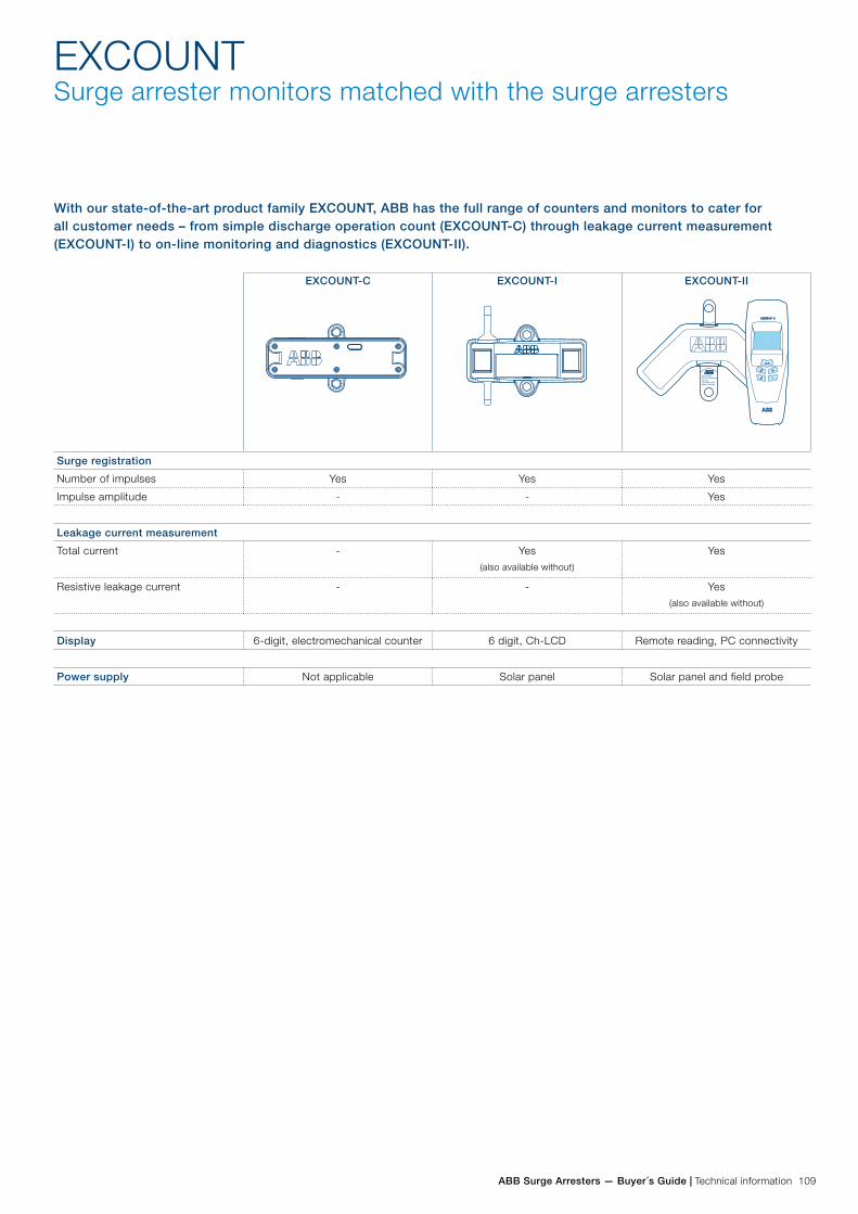
ABB Surge Arresters — Buyer´s Guide | Technical information 109
EXCOUNTSurge arrester monitors matched with the surge arresters
With our state-of-the-art product family EXCOUNT, ABB has the full range of counters and monitors to cater for all customer needs – from simple discharge operation count (EXCOUNT-C) through leakage current measurement (EXCOUNT-I) to on-line monitoring and diagnostics (EXCOUNT-II).
EXCOUNT-C EXCOUNT-I EXCOUNT-II
Surge registration
Number of impulses Yes Yes Yes
Impulse amplitude - - Yes
Leakage current measurement
Total current - Yes(also available without)
Yes
Resistive leakage current - - Yes(also available without)
Display 6-digit, electromechanical counter 6 digit, Ch-LCD Remote reading, PC connectivity
Power supply Not applicable Solar panel Solar panel and field probe
110 Technical information | ABB Surge Arresters — Buyer´s Guide
EXCOUNTMonitoring the health of surge arresters
Surge arresters present a high impedance at normal service voltage such that they behave as an insulator for the major-ity of their life. This is necessary to assure a long life for the arrester itself as well as stability of the electrical network as a whole. A deterioration of an arrester’s insulating proper-ties is therefore important to detect early before the situation becomes acute.
In order to truly evaluate the health of an arrester, testing of the kind made as routine during manufacture would need to be performed. However, such testing is not practical to make in the field and removal of the arrester to a HV lab is deemed uneconomic. Instead some kind of in-service diagnostic is required.
Surge registrationThe primary reason for the use of surge counters on modern gapless ZnO arresters is to check if a particular transmission line or phase suffers from an exceptionally high number of overvoltages leading to arrester operation — lightning faults on a line, for example. If this is the case, whilst it validates the need for the arresters, use of some preventative counter-measures may be warranted to limit the number of surges. A sudden increase in the counting rate may also indicate an internal arrester fault, in which case the arrester should be investigated further.
However, simple surge counters tell only part of the story, as they only register the number of surges according to their op-erating characteristic. The user therefore has no way of telling the magnitude of the surge and if it was significant, nor when it occurred and if it was coincident with a system event.
Leakage current measurementSurge counters can be complimented with the facility to mea-sure leakage currents (total and/or resistive), with the intention of monitoring and diagnosing the condition of the arrester and its state of fitness for continued service. However it is impor-tant to understand the validity of the information provided.
At continuous operating voltage (Uc), a metal-oxide varistor acts as a capacitor, leading to a predominantly capacitive component of current and a significantly smaller resistive part. For a complete surge arrester, the capacitive current is further dependent on stray capacitances, pollution currents on the insulator surface, number of varistor columns in parallel and the actual operating voltage. Meanwhile the small resistive component of the leakage current is temperature and voltage dependant.
Since the capacitive component of the current dominates so greatly, the total leakage current measured on a basic mA-meter will be very sensitive to the installation; making inter-pretation of the readings difficult. Furthermore, the capacitive current does not change significantly due to deterioration of the voltage-current characteristic of the surge arrester. Con-sequently, measurement of capacitive current cannot reliably indicate the condition of metal-oxide arresters. Nevertheless, increasing values may be of some use in indicating that clean-ing of the insulators is necessary.
Well-designed and tested, ABB surge arresters are maintenance-free and can reasonably be expected to have a long service life. Nevertheless, considering the type of expensive equipment which an arrester is protecting, together with how costly and devastating an unplanned power outage can be, there are good reasons for “monitoring” the condition of arresters.
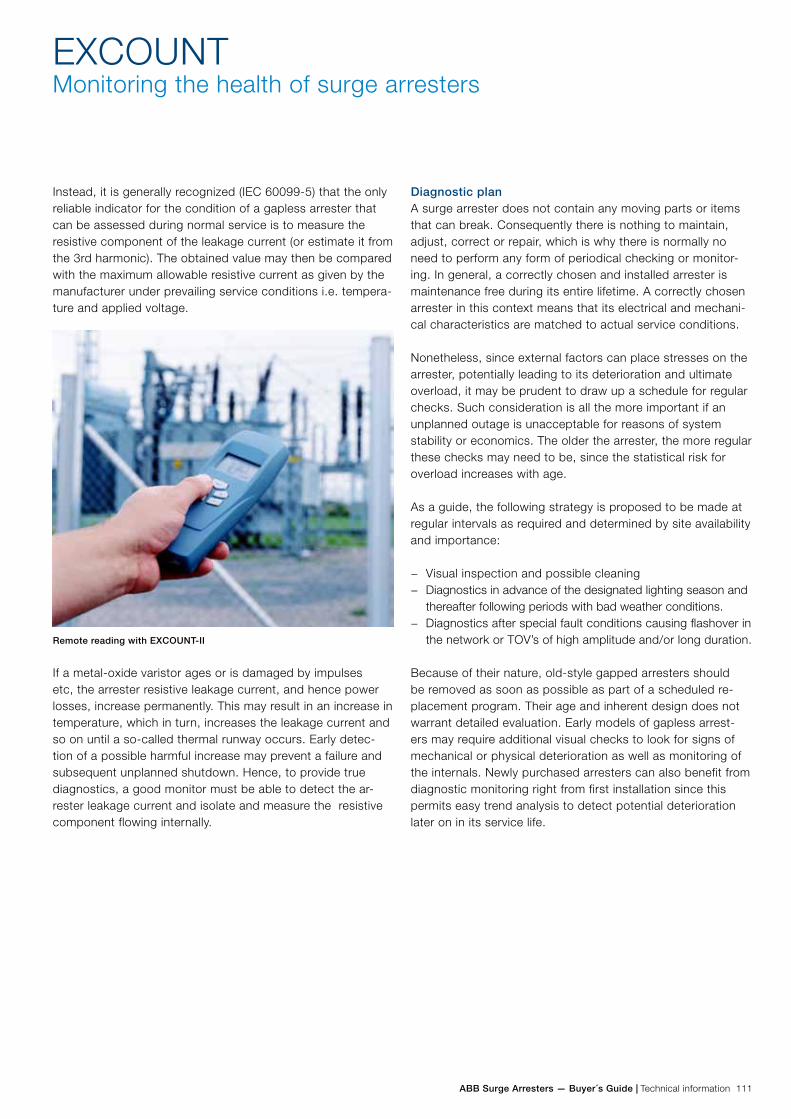
ABB Surge Arresters — Buyer´s Guide | Technical information 111
EXCOUNTMonitoring the health of surge arresters
Diagnostic planA surge arrester does not contain any moving parts or items that can break. Consequently there is nothing to maintain, adjust, correct or repair, which is why there is normally no need to perform any form of periodical checking or monitor-ing. In general, a correctly chosen and installed arrester is maintenance free during its entire lifetime. A correctly chosen arrester in this context means that its electrical and mechani-cal characteristics are matched to actual service conditions.
Nonetheless, since external factors can place stresses on the arrester, potentially leading to its deterioration and ultimate overload, it may be prudent to draw up a schedule for regular checks. Such consideration is all the more important if an unplanned outage is unacceptable for reasons of system stability or economics. The older the arrester, the more regular these checks may need to be, since the statistical risk for overload increases with age.
As a guide, the following strategy is proposed to be made at regular intervals as required and determined by site availability and importance:
− Visual inspection and possible cleaning − Diagnostics in advance of the designated lighting season and
thereafter following periods with bad weather conditions. − Diagnostics after special fault conditions causing flashover in
the network or TOV’s of high amplitude and/or long duration. Because of their nature, old-style gapped arresters should be removed as soon as possible as part of a scheduled re-placement program. Their age and inherent design does not warrant detailed evaluation. Early models of gapless arrest-ers may require additional visual checks to look for signs of mechanical or physical deterioration as well as monitoring of the internals. Newly purchased arresters can also benefit from diagnostic monitoring right from first installation since this permits easy trend analysis to detect potential deterioration later on in its service life.
Instead, it is generally recognized (IEC 60099-5) that the only reliable indicator for the condition of a gapless arrester that can be assessed during normal service is to measure the resistive component of the leakage current (or estimate it from the 3rd harmonic). The obtained value may then be compared with the maximum allowable resistive current as given by the manufacturer under prevailing service conditions i.e. tempera-ture and applied voltage.
Remote reading with EXCOUNT-II
If a metal-oxide varistor ages or is damaged by impulses etc, the arrester resistive leakage current, and hence power losses, increase permanently. This may result in an increase in temperature, which in turn, increases the leakage current and so on until a so-called thermal runway occurs. Early detec-tion of a possible harmful increase may prevent a failure and subsequent unplanned shutdown. Hence, to provide true diagnostics, a good monitor must be able to detect the ar-rester leakage current and isolate and measure the resistive component flowing internally.

112 Technical information | ABB Surge Arresters — Buyer´s Guide
EXCOUNTWhen safety comes first
EXCOUNT draws upon over 75 years of experience by ABB in the development of arresters and associated accessories. Safety, functionality and longevity are key elements which are given priority in selection and design of components. In stark contrast to many other competing products, EXCOUNT has not neglected short-circuit safety which lies inherent in the design concept.
The EXCOUNT family is characterized by:
Highest personnel safety − Explosion-proof for short-circuit currents up to 65 kA. − Same safe performance as ABB arresters.
Negligible residual voltage − Does not reduce protection margins. − Minimized risk for injury in case of accidental contact
during surges.
Maintenance free − Sealed components. − Requires no external power supply.
Long life − Moulded components, non-sensitive to humidity or
temperature variations.
Universal application − All makes and types of gapless surge arresters. − All weather and temperature conditions.
DesignThe use of an impulse current transformer with a single-turn primary ensures that the voltage drop across the counter is negligible, even at the highest impulse currents encountered in service. This leads to added personnel safety and no in-crease in the protection level of the arrester. Since no gaps or series impedance are used, there is no risk of internal arcing and consequent explosive failure in the event of a short-circuit following an arrester failure.
One further common feature with the entire EXCOUNT family is that all internal components are fully encapsulated in poly-mer. This provides sealing to IP67, which ensures no harm-ful ingress of dust or moisture as well as providing personal safety through complete protection against contact with the internals.
EXCOUNT is available in different variants, depending on the user’s needs: simple, basic or extensive.
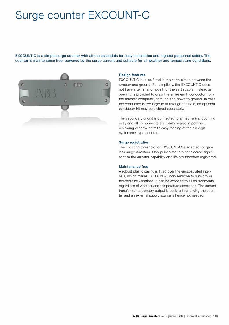
ABB Surge Arresters — Buyer´s Guide | Technical information 113
Surge counter EXCOUNT-C
Design featuresEXCOUNT-C is to be fitted in the earth circuit between the arrester and ground. For simplicity, the EXCOUNT-C does not have a termination point for the earth cable. Instead an opening is provided to draw the entire earth conductor from the arrester completely through and down to ground. In case the conductor is too large to fit through the hole, an optional conductor kit may be ordered separately.
The secondary circuit is connected to a mechanical counting relay and all components are totally sealed in polymer. A viewing window permits easy reading of the six-digit cyclometer-type counter.
Surge registrationThe counting threshold for EXCOUNT-C is adapted for gap-less surge arresters. Only pulses that are considered signifi-cant to the arrester capability and life are therefore registered.
Maintenance freeA robust plastic casing is fitted over the encapsulated inter-nals, which makes EXCOUNT-C non-sensitive to humidity or temperature variations. It can be exposed to all environments regardless of weather and temperature conditions. The current transformer secondary output is sufficient for driving the coun-ter and an external supply source is hence not needed.
EXCOUNT-C is a simple surge counter with all the essentials for easy installation and highest personnel safety. The counter is maintenance free; powered by the surge current and suitable for all weather and temperature conditions.
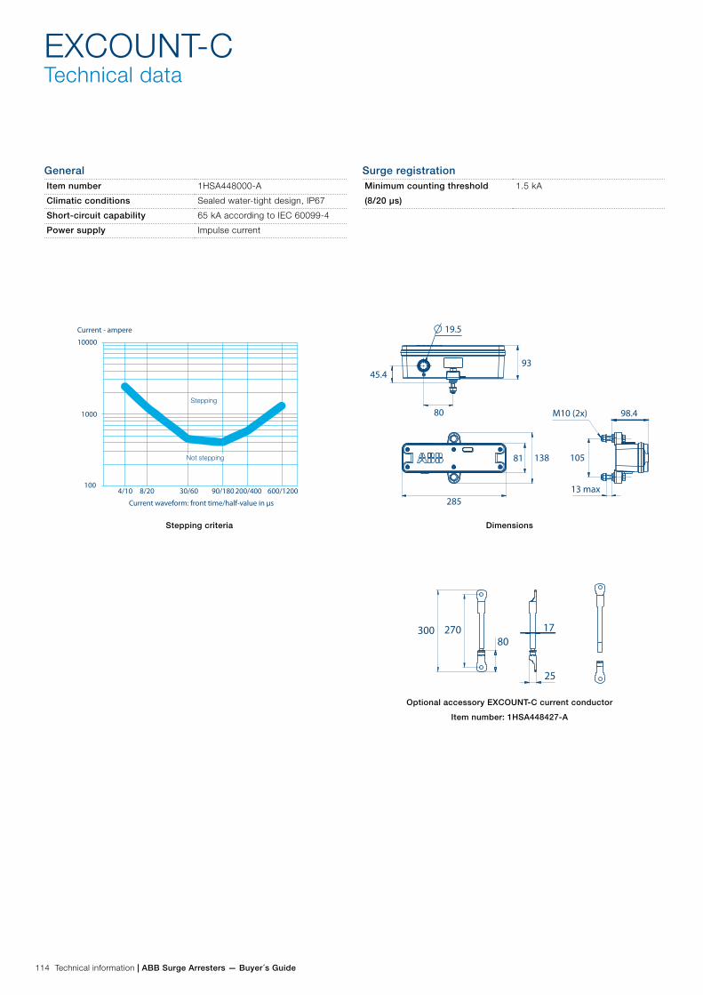
114 Technical information | ABB Surge Arresters — Buyer´s Guide
EXCOUNT-CTechnical data
GeneralItem number 1HSA448000-A
Climatic conditions Sealed water-tight design, IP67
Short-circuit capability 65 kA according to IEC 60099-4
Power supply Impulse current
Surge registrationMinimum counting threshold
(8/20 µs)
1.5 kA
Stepping criteria Dimensions
Optional accessory EXCOUNT-C current conductor
Item number: 1HSA448427-A
93
285
80
45.4
M10 (2x)
13 max
19.5
98.4
10513881
300 27080
17
25
4/10 8/20 30/60 90/180 200/400 600/1200
Stepping
Not stepping
Current waveform: front time/half-value in µs
Current - ampere
10000
1000
100
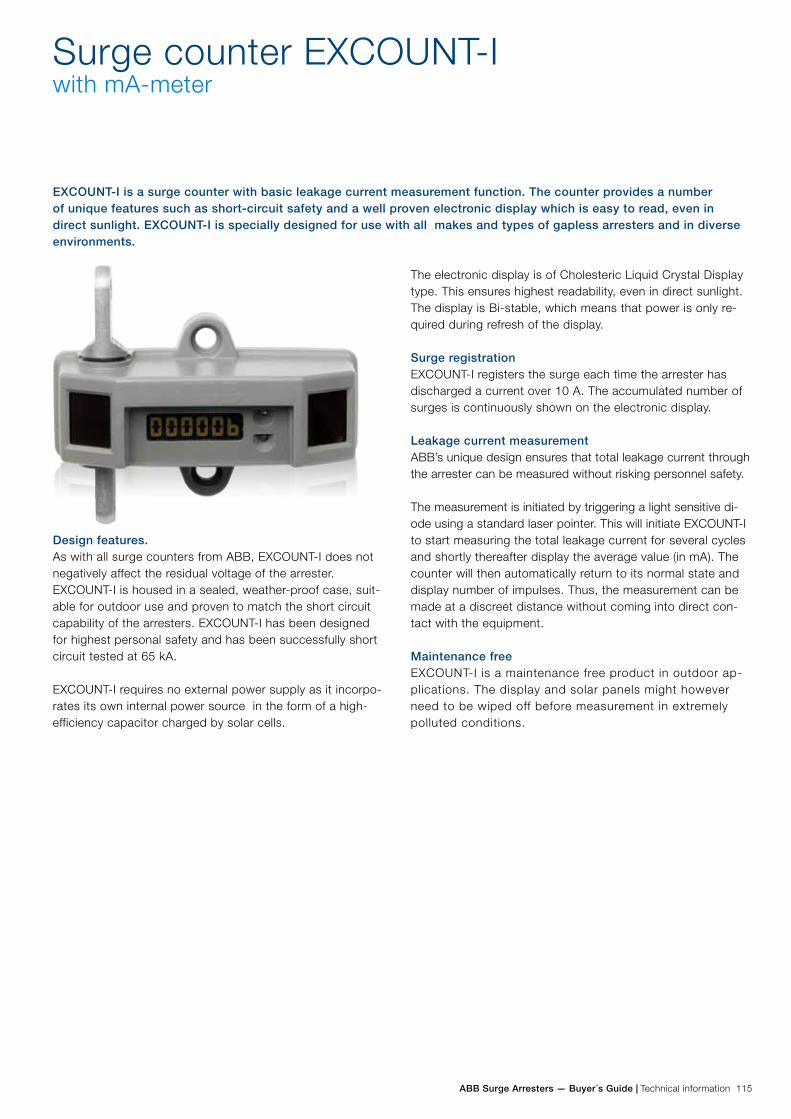
ABB Surge Arresters — Buyer´s Guide | Technical information 115
Surge counter EXCOUNT-Iwith mA-meter
Design features.As with all surge counters from ABB, EXCOUNT-I does not negatively affect the residual voltage of the arrester. EXCOUNT-I is housed in a sealed, weather-proof case, suit-able for outdoor use and proven to match the short circuit capability of the arresters. EXCOUNT-I has been designed for highest personal safety and has been successfully short circuit tested at 65 kA.
EXCOUNT-I requires no external power supply as it incorpo-rates its own internal power source in the form of a high-efficiency capacitor charged by solar cells.
EXCOUNT-I is a surge counter with basic leakage current measurement function. The counter provides a number of unique features such as short-circuit safety and a well proven electronic display which is easy to read, even in direct sunlight. EXCOUNT-I is specially designed for use with all makes and types of gapless arresters and in diverse environments.
The electronic display is of Cholesteric Liquid Crystal Display type. This ensures highest readability, even in direct sunlight. The display is Bi-stable, which means that power is only re-quired during refresh of the display.
Surge registrationEXCOUNT-I registers the surge each time the arrester has discharged a current over 10 A. The accumulated number of surges is continuously shown on the electronic display.
Leakage current measurementABB’s unique design ensures that total leakage current through the arrester can be measured without risking personnel safety.
The measurement is initiated by triggering a light sensitive di-ode using a standard laser pointer. This will initiate EXCOUNT-I to start measuring the total leakage current for several cycles and shortly thereafter display the average value (in mA). The counter will then automatically return to its normal state and display number of impulses. Thus, the measurement can be made at a discreet distance without coming into direct con-tact with the equipment.
Maintenance freeEXCOUNT-I is a maintenance free product in outdoor ap-plications. The display and solar panels might however need to be wiped off before measurement in extremely polluted conditions.
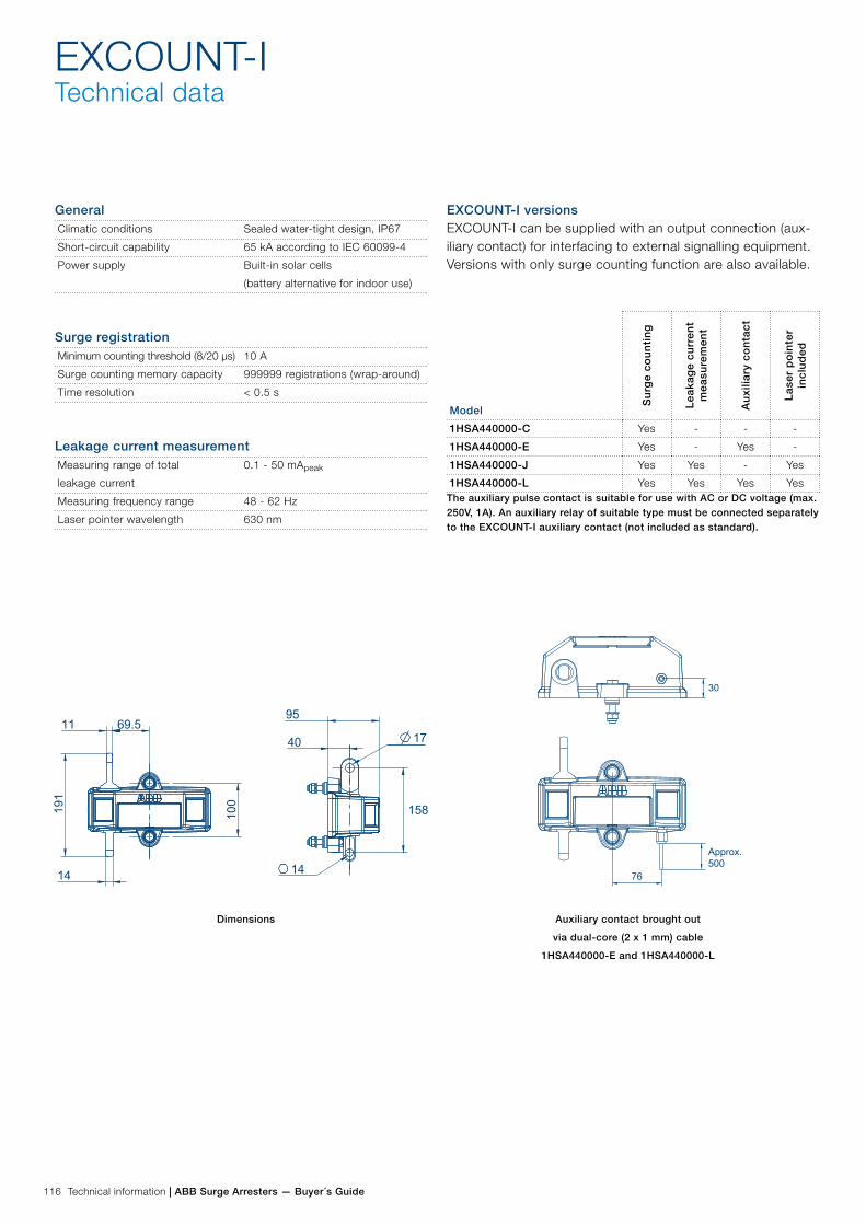
116 Technical information | ABB Surge Arresters — Buyer´s Guide
EXCOUNT-ITechnical data
GeneralClimatic conditions Sealed water-tight design, IP67
Short-circuit capability 65 kA according to IEC 60099-4
Power supply Built-in solar cells
(battery alternative for indoor use)
Surge registrationMinimum counting threshold (8/20 µs) 10 A
Surge counting memory capacity 999999 registrations (wrap-around)
Time resolution < 0.5 s
Leakage current measurementMeasuring range of total
leakage current
0.1 - 50 mApeak
Measuring frequency range 48 - 62 Hz
Laser pointer wavelength 630 nm
EXCOUNT-I versionsEXCOUNT-I can be supplied with an output connection (aux-iliary contact) for interfacing to external signalling equipment. Versions with only surge counting function are also available.
Model
Su
rge
cou
nti
ng
Lea
kag
e cu
rren
t m
easu
rem
ent
Au
xilia
ry c
on
tact
Las
er p
oin
ter
incl
ud
ed
1HSA440000-C Yes - - -
1HSA440000-E Yes - Yes -
1HSA440000-J Yes Yes - Yes
1HSA440000-L Yes Yes Yes YesThe auxiliary pulse contact is suitable for use with AC or DC voltage (max. 250V, 1A). An auxiliary relay of suitable type must be connected separately to the EXCOUNT-I auxiliary contact (not included as standard).
Dimensions Auxiliary contact brought out
via dual-core (2 x 1 mm) cable
1HSA440000-E and 1HSA440000-L
76
30
Approx.500
100
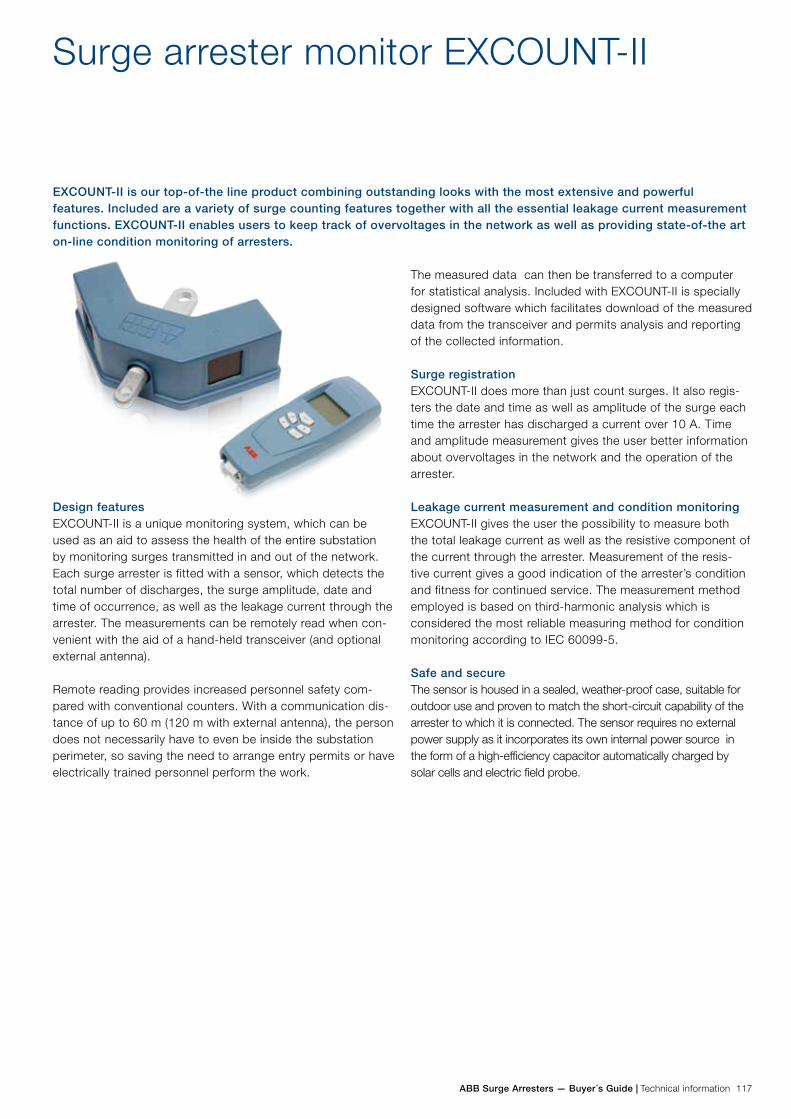
ABB Surge Arresters — Buyer´s Guide | Technical information 117
Surge arrester monitor EXCOUNT-II
Design featuresEXCOUNT-II is a unique monitoring system, which can be used as an aid to assess the health of the entire substation by monitoring surges transmitted in and out of the network. Each surge arrester is fitted with a sensor, which detects the total number of discharges, the surge amplitude, date and time of occurrence, as well as the leakage current through the arrester. The measurements can be remotely read when con-venient with the aid of a hand-held transceiver (and optional external antenna).
Remote reading provides increased personnel safety com-pared with conventional counters. With a communication dis-tance of up to 60 m (120 m with external antenna), the person does not necessarily have to even be inside the substation perimeter, so saving the need to arrange entry permits or have electrically trained personnel perform the work.
EXCOUNT-II is our top-of-the line product combining outstanding looks with the most extensive and powerful features. Included are a variety of surge counting features together with all the essential leakage current measurement functions. EXCOUNT-II enables users to keep track of overvoltages in the network as well as providing state-of-the art on-line condition monitoring of arresters.
The measured data can then be transferred to a computer for statistical analysis. Included with EXCOUNT-II is specially designed software which facilitates download of the measured data from the transceiver and permits analysis and reporting of the collected information.
Surge registrationEXCOUNT-II does more than just count surges. It also regis-ters the date and time as well as amplitude of the surge each time the arrester has discharged a current over 10 A. Time and amplitude measurement gives the user better information about overvoltages in the network and the operation of the arrester.
Leakage current measurement and condition monitoringEXCOUNT-II gives the user the possibility to measure both the total leakage current as well as the resistive component of the current through the arrester. Measurement of the resis-tive current gives a good indication of the arrester’s condition and fitness for continued service. The measurement method employed is based on third-harmonic analysis which is considered the most reliable measuring method for condition monitoring according to IEC 60099-5.
Safe and secureThe sensor is housed in a sealed, weather-proof case, suitable for outdoor use and proven to match the short-circuit capability of the arrester to which it is connected. The sensor requires no external power supply as it incorporates its own internal power source in the form of a high-efficiency capacitor automatically charged by solar cells and electric field probe.
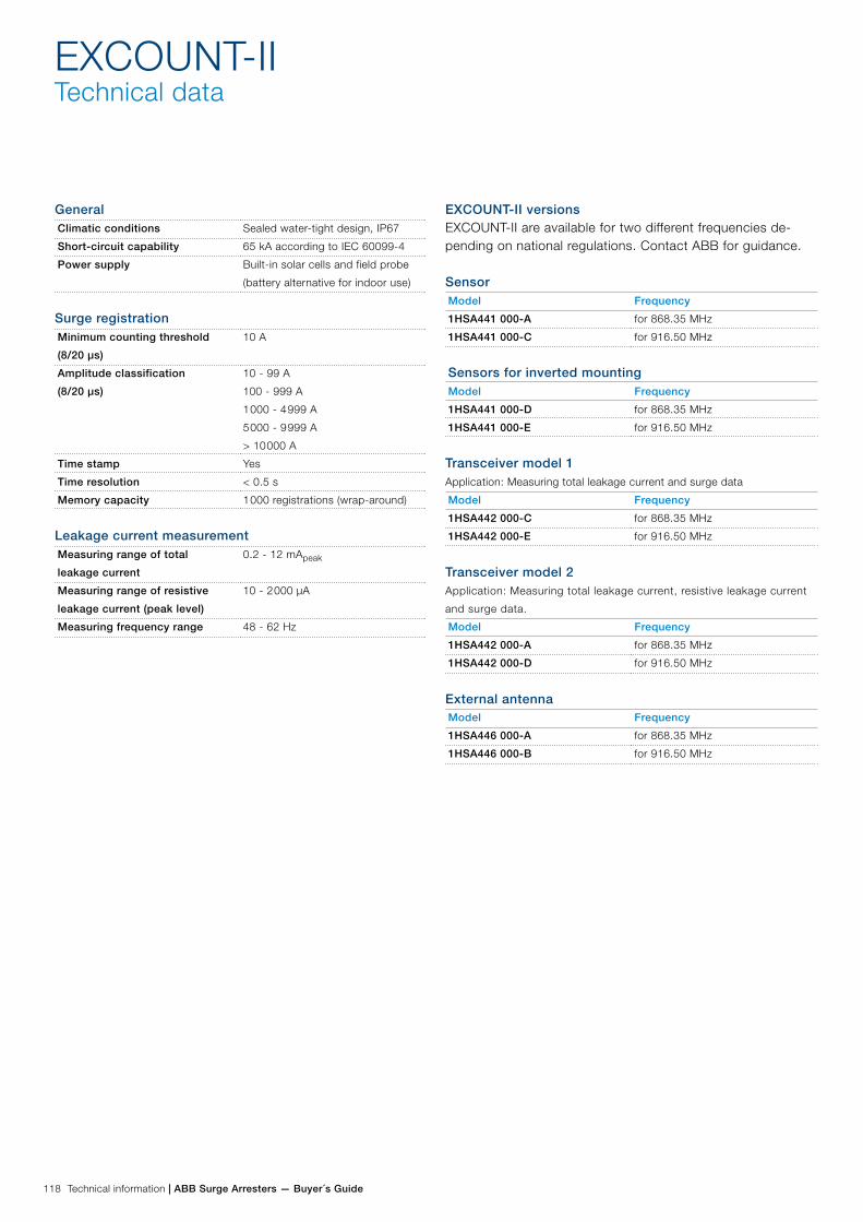
118 Technical information | ABB Surge Arresters — Buyer´s Guide
EXCOUNT-IITechnical data
GeneralClimatic conditions Sealed water-tight design, IP67
Short-circuit capability 65 kA according to IEC 60099-4
Power supply Built-in solar cells and field probe
(battery alternative for indoor use)
Surge registrationMinimum counting threshold
(8/20 µs)
10 A
Amplitude classification
(8/20 µs)
10 - 99 A
100 - 999 A
1 000 - 4 999 A
5 000 - 9 999 A
> 10 000 A
Time stamp Yes
Time resolution < 0.5 s
Memory capacity 1 000 registrations (wrap-around)
Leakage current measurementMeasuring range of total
leakage current
0.2 - 12 mApeak
Measuring range of resistive
leakage current (peak level)
10 - 2 000 µA
Measuring frequency range 48 - 62 Hz
EXCOUNT-II versionsEXCOUNT-II are available for two different frequencies de-pending on national regulations. Contact ABB for guidance.
SensorModel Frequency
1HSA441 000-A for 868.35 MHz
1HSA441 000-C for 916.50 MHz
Sensors for inverted mountingModel Frequency
1HSA441 000-D for 868.35 MHz
1HSA441 000-E for 916.50 MHz
Transceiver model 1Application: Measuring total leakage current and surge data
Model Frequency
1HSA442 000-C for 868.35 MHz
1HSA442 000-E for 916.50 MHz
Transceiver model 2 Application: Measuring total leakage current, resistive leakage current
and surge data.
Model Frequency
1HSA442 000-A for 868.35 MHz
1HSA442 000-D for 916.50 MHz
External antennaModel Frequency
1HSA446 000-A for 868.35 MHz
1HSA446 000-B for 916.50 MHz
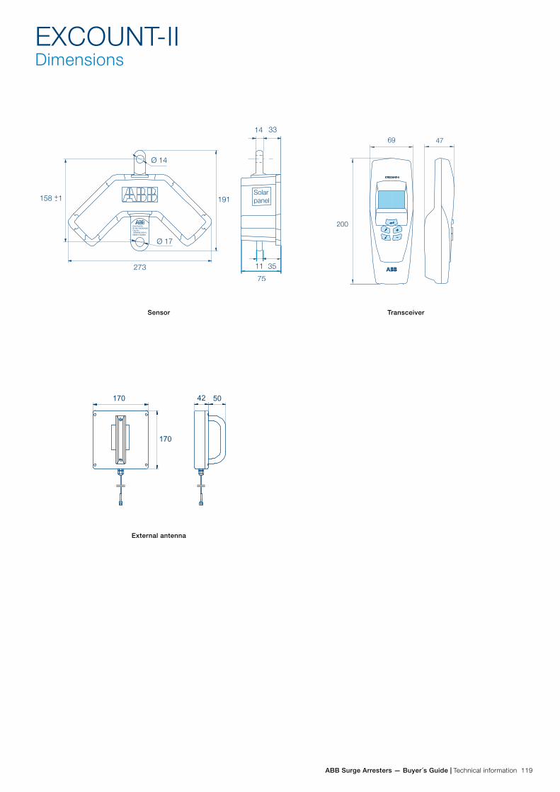
ABB Surge Arresters — Buyer´s Guide | Technical information 119
Sensor Transceiver
External antenna
EXCOUNT-IIDimensions

120 Technical information | ABB Surge Arresters — Buyer´s Guide
Purchase order
Project Handled by, e-mail or fax Tender reference no (if any)
Buyer Date (yyyy-mm-dd) Buyer reference
End user End user reference (if any)
Shipping terms Destination Means of transport
Freight forwarder (if FCA or FOB) Payment terms
Goods marking Delivery address
Inspection of routine tests Routine test standard Documentation language Rating plate language Currency
ItemsQuantity Arrester type designation
Color (porcelain) Line terminal Earth terminal Insulating base
Delivery date (EXW) yyyy-mm-dd Unit price (if known) Total price (if known)
Quantity Arrester type designation
Color (porcelain) Line terminal Earth terminal Insulating base
Delivery date (EXW) yyyy-mm-dd Unit price (if known) Total price (if known)
Quantity Arrester type designation
Color (porcelain) Line terminal Earth terminal Insulating base
Delivery date (EXW) yyyy-mm-dd Unit price (if known) Total price (if known)
Quantity Arrester type designation
Color (porcelain) Line terminal Earth terminal Insulating base
Delivery date (EXW) yyyy-mm-dd Unit price (if known) Total price (if known)
It is recommended that the following form is used when ordering EXLIM/PEXLIM/TEXLIM surge arresters and accessories. Send to fax: +46 (0)240 179 83 or mail to [email protected].
No Yes
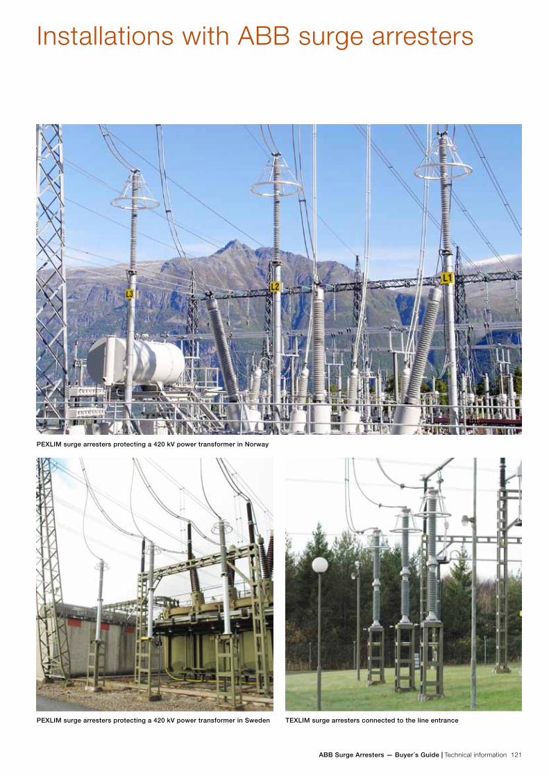
ABB Surge Arresters — Buyer´s Guide | Technical information 121
Installations with ABB surge arresters
PEXLIM surge arresters protecting a 420 kV power transformer in Norway
PEXLIM surge arresters protecting a 420 kV power transformer in Sweden TEXLIM surge arresters connected to the line entrance

122 Technical information | ABB Surge Arresters — Buyer´s Guide
PEXLIM surge arresters connected to the 420 kV the secondary winding on a step-up transformer in a nuclear power plant
PEXLIM surge arresters protecting a cable entrance EXLIM surge arresters protecting a 420 kV power transformer


Contact us
Doc
umen
t ID
1H
SM
954
3 12
-00e
n, H
igh
Volta
ge S
urge
Arr
este
rs,
Byu
er´s
Gui
de,
Ed
ition
13,
201
8-02ABB AB
High Voltage Products Surge Arresters SE-771 80 Ludvika, Sweden Phone: +46 (0)240 78 20 00 Fax: +46 (0)240 179 83 www.abb.com/arrestersonline
©Copyright 2018 ABB
All rights reserved
NOTE: ABB AB works continuously with product
improvements. We therefore reserve the right to
change designs, dimensions and data without prior
notice.
Related Documents