High Voltage Battery System Copyright 2010 All rights reserved. No part of this material may be reproduced, stored in any retrieval system or transmitted in any ⓒ form or by any means without the written permission of Kia Motors Corporation.

High Voltage Battery System Copyright ⓒ 2010 All rights reserved. No part of this material may be reproduced, stored in any retrieval system or transmitted.
Dec 22, 2015
Welcome message from author
This document is posted to help you gain knowledge. Please leave a comment to let me know what you think about it! Share it to your friends and learn new things together.
Transcript

High Voltage Battery System
Copyright 2010 All rights reserved. No part of this material may be reproduced, stored in any retrieval system or transmitted in any form or by any means without the written permission of Kia Motors Corporation.ⓒ

2Contents
1. General
2. System Components
3. Battery Management System
4. Diagnosis
5. Cautions

3
Alkali Type
Nickel-cadmium
Ni-MH
Acidity Type
Lead-acid
Lithium Type
Lithium metal
Gel/Solid electrolyte
Organic solution electrolyte
Li-ion Polymer
Lithium-ion
Nickel-Metal Hydride
Lithium-ion
Lithium-ion Polymer
HEV Battery
Representative secondary battery
Types of Rechargeable Battery
General

4
Alkali TypeAlkali Type
Nickel-cadmium(Ni-Cd)
Nickel-Metal Hydride
(Ni-MH)
Ni-MH CapacityNi-MH Capacity:: aboutabout 1~5 kWh1~5 kWh(Normal battery(Normal battery : about: about 0.3~1.0 kWh)0.3~1.0 kWh)
Cell voltage : 1.2V
Self discharge rate: 10~30%
Memory effect: YES
Application : Walkman,CD player
Performance : Ni-MH 〉 Ni-Cd
Alkaline Battery
General

5
Effect which cause to hold less charge because battery Effect which cause to hold less charge because battery remember the smaller capacityremember the smaller capacity
If 80% discharged and then fully charged,→ only 80% capacity can be used
If 64%(80% of 80%) discharged and then fully charged,→ only 64% capacity can be used
What is memory effect
General

6
Prius Insight
Most of HEV → Using Ni-MH Battery
Nickel-Metal Hydride Battery (Ni-MH)
General

7
Lithium type
Lithium-ion(Li-ion)
Lithium-ion Polymer(LiPB)
Cell voltage: 3.75V
Self discharge rate: 5% or less
Memory effect: NO
Application: Laptop, Digital camera,
Cellular phone, etc
Performance: High Voltage,
High energy density
Representative secondary battery
Lithium-ion Polymer Battery (NiPB)
General

8
Lithium-ion Lithium-ion polymer batterypolymer battery
World’s first lithium-ion polymer battery for HEVWorld’s first lithium-ion polymer battery for HEV
TF Optima Hybrid High Voltage Battery
General
9
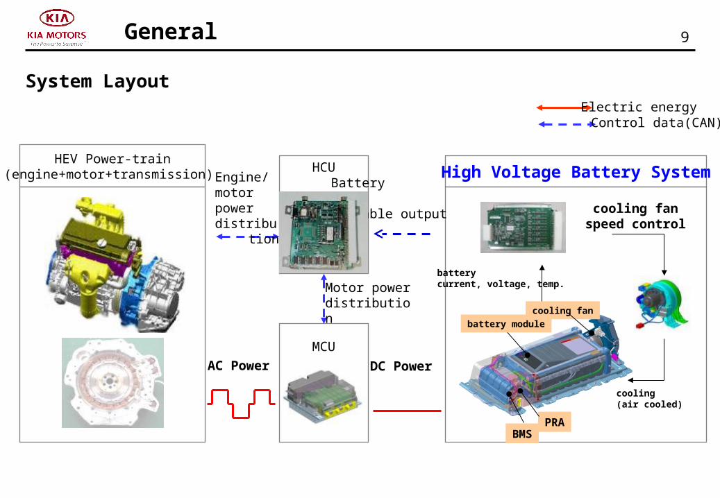
MCU
HCUHEV Power-train
(engine+motor+transmission) High Voltage Battery System
Motor power distribution
BatterySOC,variable output
Engine/motorpower distribution
Control data(CAN)Electric energy
batterycurrent, voltage, temp.
cooling fan speed control
cooling (air cooled)
AC Power DC Power
battery module
BMSPRA
cooling fan
System Layout
General

10Components
High Voltage Battery System Components
Lithium-ion polymer batteryLithium-ion polymer battery 270V / 5.3Ah, 72Cells in series 270V / 5.3Ah, 72Cells in series Enhance safetyEnhance safety -Prevent overcharging -Prevent overcharging
High voltage battery
Maintain proper temperatureMaintain proper temperature - Equipped with BLDC - Equipped with BLDC** cooling fan cooling fan - Increase air flow & Reduce noise - Increase air flow & Reduce noise
Cooling system
Voltage, Current, TemperatureVoltage, Current, Temperature sensingsensing SOCSOC** estimation, Power-cut, Cooling control,estimation, Power-cut, Cooling control, Relay control, Cell balancing, Diagnosis Relay control, Cell balancing, Diagnosis
BMS*
RelayRelay ON/OFF controlON/OFF control Battery current checkBattery current check
Power Relay Ass’y(PRA)
BLDC: Brushless DC, BMS: Battery Management System, SOC: State of charge

11Components
Location of High Voltage Battery
Inside of trunkInside of trunk
Cover openedCover opened
High voltage battery module assemblyHigh voltage battery module assembly
Inside of steel coverInside of steel cover

12
Cell
Module
Module Assembly
8Cells ⇒ 1Module
9Modules ⇒ 1Module Assembly
Components
Composition of High Voltage Battery
3.75V
(8 X 3.75V ⇒ 30V)
(9 X 30V ⇒ 270V)

13Components
Operation of High Voltage Battery (Li-ion)
Organic electrolyte
Mn(Cobalt) Lithium Oxygen Graphite Lithium-ion
(+) Polarity (-) PolarityCharge
Discharge
LiCoO2 + Co Li1-xCoO2 + LixCoDischarge
charge

14Components
Location of Power Relay Assembly
High Voltage Battery SystemHigh Voltage Battery System

15Components
Composition of Power Relay Assembly
High voltage Relay (+) (-)High voltage Relay (+) (-)
Pre-charge RelayPre-charge Relay
CapacitorCapacitor
Pre-charge Resistance(?)Pre-charge Resistance(?)

16
Equipped with Pre-charge circuit Equipped with Pre-charge circuit to protect electrical componentsto protect electrical components
Main Relay (-)Main Relay (-)
Main Relay (+)Main Relay (+)
Pre-charge Pre-charge relayrelay
CapacitorCapacitor
Pre-charge Pre-charge resistanceresistance
Inverter(+)Inverter(+)
Inverter(-)Inverter(-)
Components
Power Relay Circuit
LDCLDCLDCLDC

17Components
Power Relay Operating Sequence
K1 : Pre-charge relayK2 : Main relay (+)K3 : Main relay(-)
K1 : Pre-charge relayK2 : Main relay (+)K3 : Main relay(-)

18Components
Relay Control

19Components
Pre-charge Relay Control
20Components
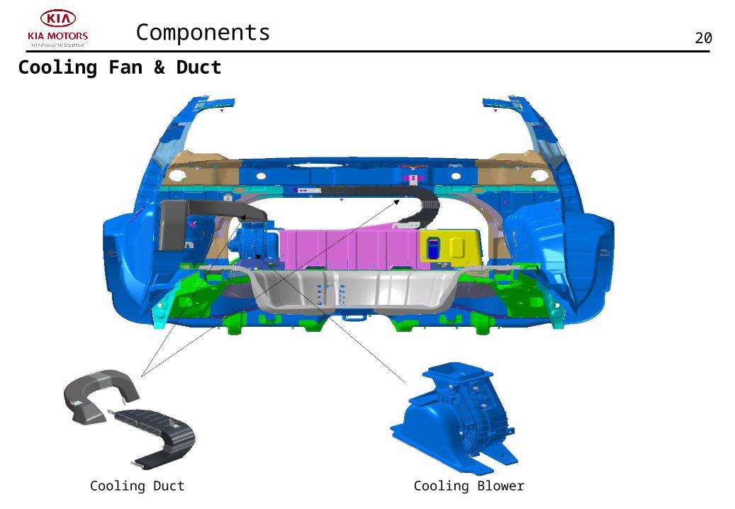
Cooling Fan & Duct
Cooling Duct Cooling Blower

21Components
BMS Hardware
Item Spec Remark
CPU 16bit XC167 (Infineon)
Battery Cell Voltage Sensing
72 Cells Exclusive sensing chip
Cell Balance 150mA@4V Bucking
Current Sensing -200 ~ 200A, 10Bit -
Temp Sensing 11 chBattery 5 + External
Device 1 + Aux. Battery 1ch
Insulation Resistance
Sensing0.01~1㏁ -
Cooling Fan Control
FCTL (relay control)FSPEED (PWM output)VF (speed monitoring
input)
BLDC Motor
Relay Control 3 ch Pre / Main (+)/(-)
Interlock 1 ch Safety plug
CAN Comm. 2 ch C-CAN / H-CAN

22Components
BMS Framework
cell voltage cell temp current intake temp
③ control cooling system
② limit output ① Estimate SOC
④ control relay
⑤ troubleshooting SOC
relaysequence
fan speed Error Code
battery module battery pack battery system
Insulationresistance
high voltagerelay
cooling fanlamp
(Cluster)
Variable Power
Key On/Off Info
SOC Mgmt
Power Distribution
BMS-Major Function
measure
batterycontrol device
Drivemechanism
⑥ cell balancing

23Battery Management System
Functions
SOC monitoring
Input / Output power limit calculation
Cell balancing
Cooling fan control
High voltage power relay control
Self diagnosis
SOC monitoring
Input / Output power limit calculation
Cell balancing
Cooling fan control
High voltage power relay control
Self diagnosis
24Battery Management System
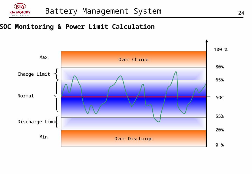
Over Charge
Over Discharge
0 %0 %
NormalNormal
Discharge LimitDischarge Limit
Charge LimitCharge Limit
MaxMax
100 %100 %
SOCSOC
MinMin
65%65%
55%55%
80%80%
20%20%
SOC Monitoring & Power Limit Calculation

25Battery Management System
- 20. 00
- 15. 00
- 10. 00
- 5. 00
0. 00
5. 00
10. 00
15. 00
20. 00
25. 00
- 30미만 - 30 - 25 - 15 - 10 - 5 0 5 10 15 20 25 35 45 50 55 60 이상
Temp (℃)
Output
(kW)
Charge
Discharge
Usable
Unusable
Unusable
Cooling Fan Control
Optimal Temp: Average of 30°
Min. Storage Temp.
Min. Charge/Discharge Temp.
Warning Operating Temp.Max. Charge/Discharge
Temp.Warning
Max. Storage Temp.
-40° -30° - 29° ∼ 49° 50° 55° 65°

26Battery Management System
배터리+
-
U/V/W
전원차단장치
전원 배선
모터
인버터 Battery+
-
U/V/WPower Cable
Motor
Inveter
인버터
냉각팬
High Voltage Drive Component
High Voltage A/C Component
AIRBAG
ECU
TCU
HV MAIN RELAY(-)
BMS
HV PRECHARGE RELAY
LDC
FATC
IGKey
HCU
ON/OFFReq.
OFF Req.
RelayDrive
ON/OFFStatus
MCU
HV MAIN RELAY(+)
High Voltage Power Relay Control

27
High Voltage Power Relay Control
Battery Management System
_IG KEY
INV Cap. Volt.
Main Relay(+)
Pre- charge Relay
Main Relay(- )
Main Relay ON Status
Pre-charging Time : 200ms
28
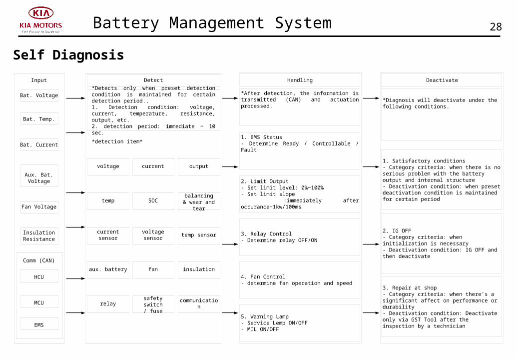
Self Diagnosis
Battery Management System
Input
Bat. Voltage
Bat. Temp.
Bat. Current
Aux. Bat. Voltage
Fan Voltage
InsulationResistance
Comm (CAN)
HCU
MCU
EMS
Detect Handling Deactivate
*Detects only when preset detection condition is maintained for certain detection period..1. Detection condition: voltage, current, temperature, resistance, output, etc.2. detection period: immediate ~ 10 sec.
*detection item*
voltage current output
temp SOC balancing& wear and tear
current sensor voltage sensor temp sensor
aux. battery fan insulation
relay safety switch/ fuse
communication
*After detection, the information is transmitted (CAN) and actuation processed.
1. BMS Status- Determine Ready / Controllable / Fault
2. Limit Output- Set limit level: 0%~100%- Set limit slope :immediately after occurance~1kw/100ms
3. Relay Control- Determine relay OFF/ON
4. Fan Control- determine fan operation and speed
5. Warning Lamp- Service Lemp ON/OFF- MIL ON/OFF
*Diagnosis will deactivate under the following conditions.
1. Satisfactory conditions- Category criteria: when there is no serious problem with the battery output and internal structure- Deactivation condition: when preset deactivation condition is maintained for certain period
2. IG OFF- Category criteria: when initialization is necessary- Deactivation condition: IG OFF and then deactivate
3. Repair at shop- Category criteria: when there’s a significant affect on performance or durability- Deactivation condition: Deactivate only via GST Tool after the inspection by a technician

29
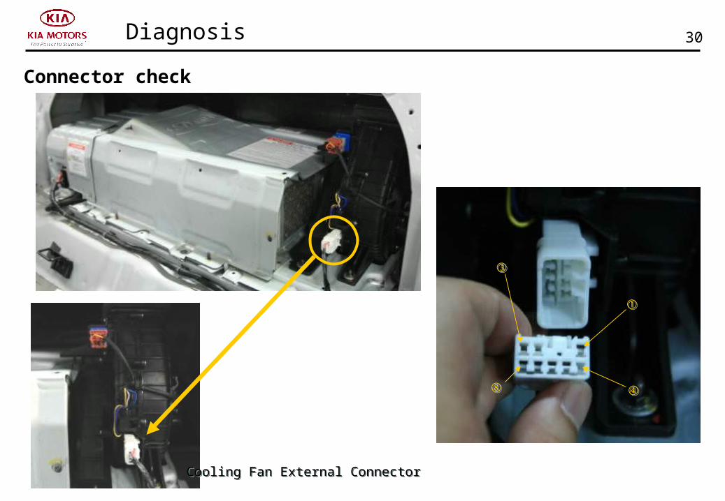
Connector check
Diagnosis
BMS External ConnectorBMS External Connector
①①
⑩⑩
⑪⑪
2222
30
Connector check
Diagnosis
Cooling Fan External ConnectorCooling Fan External Connector
①①
③③
④④⑧⑧

31Diagnosis
Current Data 1TFTF

32Diagnosis
Current Data 2TFTF

33
Current Data 3
Diagnosis
TFTF

34Diagnosis
Actuation TestTFTF

35Cautions
Technician must disconnect safety plug !Technician must disconnect safety plug !
Inside of trunk
Safety PlugSafety Plug
Cautions while servicing on high voltage circuit

36Cautions
How to release safety plug
Main fuse
Lock grip

37Cautions
Orange color means high voltage cable or componentsOrange color means high voltage cable or components
High Voltage WarningHigh Voltage Warning
Cautions for high voltage

38Cautions
High voltage checking point
ConnectorPin No
Level
PRA(INV + /-)
1IG OFF : 0VIG ON : 270V (198V~309V)
2
When servicing high voltage system, checking voltage must be lower than 10V.
Must be cautious when checking high voltage.
When servicing high voltage system, checking voltage must be lower than 10V.
Must be cautious when checking high voltage.
Related Documents