59 th ILMENAU SCIENTIFIC COLLOQUIUM Technische Universität Ilmenau, 11 – 15 September 2017 URN: urn:nbn:de:gbv:ilm1-2017iwk-034:1 ©2017 - TU Ilmenau HIGH TEMPERATURE PARTICLE JET EROSION OF NICKEL- AND COBALT-BASED ALLOYS V. Wesling, R. Reiter, J. Hamje, T. Müller Institute of Welding and Machining (ISAF), Clausthal University of Technology Agricolastraße 2, 38678 Clausthal-Zellerfeld, Germany [email protected] 1. ABSTRACT Higher operating temperatures can increase the effectiveness of different technical processes, e.g. turbines, combustion furnaces and cyclone separators. The combination of the increased temperatures with the stresses and strains necessitate new hardwearing materials. The research of the influence of high temperatures and oxidation on the wear resistance has mainly been conducted on single-phase materials. In the current research, the influences of temperature, impact angle and kinetic energy of the particles are examined. Therefore, high temperature particle jet erosion tests of a nickel-based and a cobalt-based alloy were conducted. Hastealloy ® C22 and Ultimet ® Alloy were chosen, due to the high resistances against both corrosion and abrasion. The specimens are PTA- welded layers on steel plates, partially reinforced with different carbides, including fused tungsten carbides and titanium carbides. Initially, only carbides of the same grain size were used. Further tests were conducted on alloys with a mixture of carbides, varying in type and size. These tests were conducted in a specially designed testing machine with a variety of parameters. This includes temperatures of 750 °C, different particle velocities and impact angles. Oxidation tests were used to isolate the influence of the corrosion on the wear resistance at high temperatures. The results of this research provide a better understanding of the properties and capabilities of the alloys and carbides. 2. INTRODUCTION Wear is one of the main expanse factors. According to the survey “Tribologie; ehem. Bundesministerium für Forschung und Technik[1]”, abrasion is responsible for half of the damage events caused by wear. This includes erosive wear by particle impingement. A significant factor on the rate of material loss is the ratio of the hardnesses of abrasive and material. A relevant material loss normally occurs when the hardness of the abrasive exceeds the hardness of the material (picture 1 left). Equally important is the angle of impingement. Ductile materials are vulnerable to impingement at small angles, whereas ceramics tend to have the maximal material loss at high angles of impingement (picture 1 right).

Welcome message from author
This document is posted to help you gain knowledge. Please leave a comment to let me know what you think about it! Share it to your friends and learn new things together.
Transcript

59th ILMENAU SCIENTIFIC COLLOQUIUM Technische Universität Ilmenau, 11 – 15 September 2017
URN: urn:nbn:de:gbv:ilm1-2017iwk-034:1
©2017 - TU Ilmenau
HIGH TEMPERATURE PARTICLE JET EROSION OF NICKEL- AND
COBALT-BASED ALLOYS
V. Wesling, R. Reiter, J. Hamje, T. Müller
Institute of Welding and Machining (ISAF), Clausthal University of Technology
Agricolastraße 2, 38678 Clausthal-Zellerfeld, Germany
1. ABSTRACT
Higher operating temperatures can increase the effectiveness of different technical processes,
e.g. turbines, combustion furnaces and cyclone separators. The combination of the increased
temperatures with the stresses and strains necessitate new hardwearing materials. The
research of the influence of high temperatures and oxidation on the wear resistance has
mainly been conducted on single-phase materials.
In the current research, the influences of temperature, impact angle and kinetic energy of the
particles are examined. Therefore, high temperature particle jet erosion tests of a nickel-based
and a cobalt-based alloy were conducted. Hastealloy®
C22 and Ultimet® Alloy were chosen,
due to the high resistances against both corrosion and abrasion. The specimens are PTA-
welded layers on steel plates, partially reinforced with different carbides, including fused
tungsten carbides and titanium carbides. Initially, only carbides of the same grain size were
used. Further tests were conducted on alloys with a mixture of carbides, varying in type and
size.
These tests were conducted in a specially designed testing machine with a variety of
parameters. This includes temperatures of 750 °C, different particle velocities and impact
angles. Oxidation tests were used to isolate the influence of the corrosion on the wear
resistance at high temperatures.
The results of this research provide a better understanding of the properties and capabilities of
the alloys and carbides.
2. INTRODUCTION
Wear is one of the main expanse factors. According to the survey “Tribologie; ehem.
Bundesministerium für Forschung und Technik[1]”, abrasion is responsible for half of the
damage events caused by wear. This includes erosive wear by particle impingement.
A significant factor on the rate of material loss is the ratio of the hardnesses of abrasive and
material. A relevant material loss normally occurs when the hardness of the abrasive exceeds
the hardness of the material (picture 1 left). Equally important is the angle of impingement.
Ductile materials are vulnerable to impingement at small angles, whereas ceramics tend to
have the maximal material loss at high angles of impingement (picture 1 right).

©2017 - TU Ilmenau 2
picture 1: influencing factors on erosive wear, ISAF
The correlation between the hardness of the material and the angle dependent maximal
material loss can be explained by examining the wear mechanisms.
picture 2: wear mechanisms depending on the angle of impingement, ISAF
Materials under the stress of erosion are more or less vulnerable to these mechanisms, mostly
depending on their hardness. Therefore, the examination of hard particle reinforced alloys
involves the examination of wear properties of the alloy and hard particles as well as the
amount, size and distribution of particles.
The oxidation of the alloys can have a significant influence on the wear behaviour. The
resistance against erosion and corrosion can be determined through the properties and
oxidation rate of the forming oxides.
picture 3: protective and non-protective oxides, hps.hs-regensburg.de
©2017 - TU Ilmenau 3
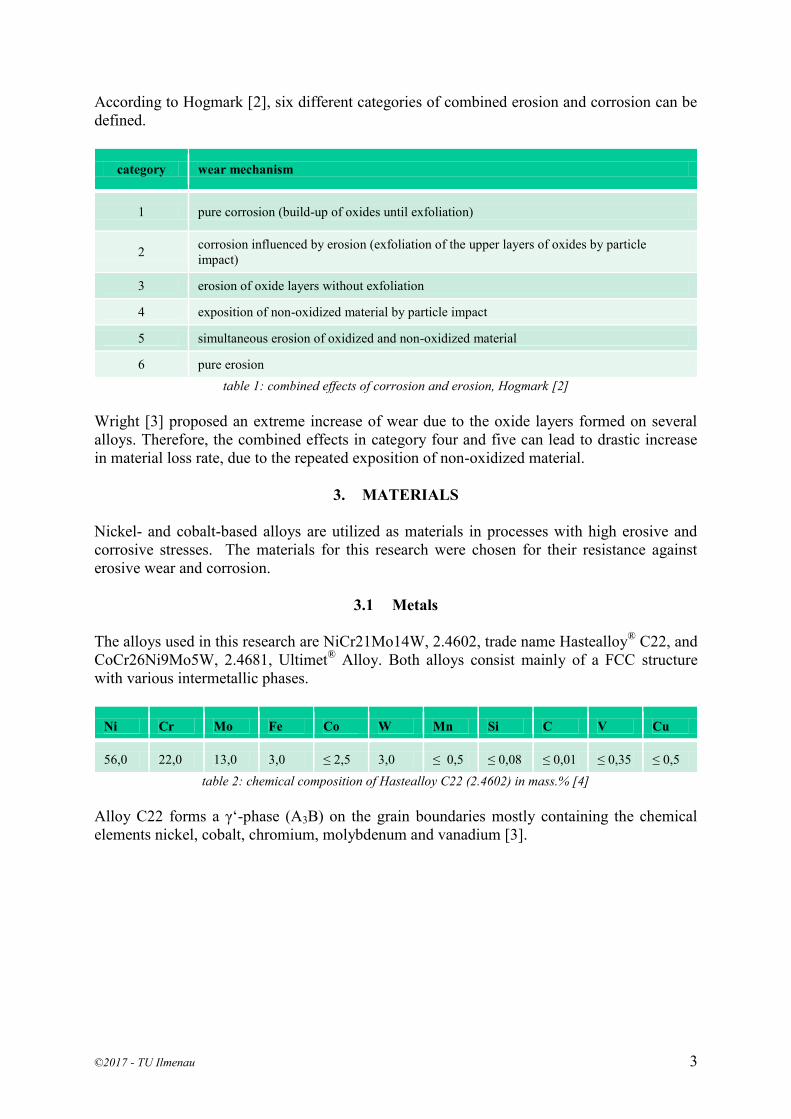
According to Hogmark [2], six different categories of combined erosion and corrosion can be
defined.
category wear mechanism
1 pure corrosion (build-up of oxides until exfoliation)
2 corrosion influenced by erosion (exfoliation of the upper layers of oxides by particle
impact)
3 erosion of oxide layers without exfoliation
4 exposition of non-oxidized material by particle impact
5 simultaneous erosion of oxidized and non-oxidized material
6 pure erosion
table 1: combined effects of corrosion and erosion, Hogmark [2]
Wright [3] proposed an extreme increase of wear due to the oxide layers formed on several
alloys. Therefore, the combined effects in category four and five can lead to drastic increase
in material loss rate, due to the repeated exposition of non-oxidized material.
3. MATERIALS
Nickel- and cobalt-based alloys are utilized as materials in processes with high erosive and
corrosive stresses. The materials for this research were chosen for their resistance against
erosive wear and corrosion.
3.1 Metals
The alloys used in this research are NiCr21Mo14W, 2.4602, trade name Hastealloy®
C22, and
CoCr26Ni9Mo5W, 2.4681, Ultimet® Alloy. Both alloys consist mainly of a FCC structure
with various intermetallic phases.
Ni Cr Mo Fe Co W Mn Si C V Cu
56,0 22,0 13,0 3,0 ≤ 2,5 3,0 ≤ 0,5 ≤ 0,08 ≤ 0,01 ≤ 0,35 ≤ 0,5
table 2: chemical composition of Hastealloy C22 (2.4602) in mass.% [4]
Alloy C22 forms a γ‘-phase (A3B) on the grain boundaries mostly containing the chemical
elements nickel, cobalt, chromium, molybdenum and vanadium [3].

©2017 - TU Ilmenau 4
picture 4: REM picture of C22 with FTC, ISAF
The intermetallic γ‘-phase increases the hardness and creep resistance of the alloy.
In the cobalt-based alloy, σ-, µ- or Laves-phases can be formed [5]. The σ-phase has a high
influence on the wear properties of this alloy. These phases form in the temperature range of
this research, leading to higher hardness of the alloy [6],[7]. The proof will follow in chapter
8.
Co Cr Ni Mo Fe W Mn Si N C
54,0 26,0 9,0 5,0 3,0 2,0 0,8 0,3 0,08 0,06
table 3: chemical composition of Ultimet Alloy (2.4681) in mass.% [4]
3.2 Carbides
The carbides initially used in this research are titanium carbide (TiC) and fused tungsten
carbide (FTC).
Melting temperature
[°C]
ΔFH0
[kJ/mol, 25°C] hardness
[HV0,1]
Titanium carbide 3050 - 3080 -184,5 3200
Fused Tungsten Carbide 2525
WC: -40,16
W2C: -26,36 2360
table 4: properties of the carbides [8][9]
Fused tungsten carbide has the lowest melting point and is the least stable of these carbides. It
dissipates faster in molten metal and has the highest oxidation rate. The inner structure
prevents the crack growth, making it more resilient against the particle impingement.
Titanium carbide (here sintered TiC) has the highest melting temperature, standard enthalpy
of formation and hardness. The oxidation rate of TiC is therefore lower than the oxidation rate
Fused
tungsten
carbide
γ‘-phase on
grain
boundaries
Face-
centered
cubic
Secondary
carbides

©2017 - TU Ilmenau 5
of the tungsten carbides. But because of the high hardness and possible crystallographic
defects, it tends to shatter under the stress of particle impact.
3.3 Reinforced Alloys
The reinforced alloys tested for this research are listed in the following table.
Carbide content
[mass.%]
Carbide content
[vol.%]
Grain size
[µm]
Density
[g/cm³]
C22 + TiC 20 30,39 -90 +45 7,16
C22 + FTC 45 29,9 -90 +45 12,18
Ultimet + TiC 19,85 30,05 -90 +45 7,51
Ultimet+ FTC 45,5 30,19 -90 +45 12,48
table 5: Reinforced alloys and their carbide content
The carbide content is limited to a maximum of 30 vol.%, which is still considered
economically.
4. TESTING MACHINE
The high temperature solid particle impingement tests are conducted in a testing machine
specially designed by the Institute of Machining and Welding. The testing temperature ranges
from 20°C up to 800°C. The tests can be conducted with different abrasives with particle sizes
between 10 µm and 800 µm and abrasive mass flows of up to 1000 g/min. Depending on the
particle size, impact velocities of up to 100 m/s are possible. The angle of impact is steplessly
adjustable between 20° and 90°.
picture 5: high temperature solid particle impingement testing machine, schematic diagram, ISAF

©2017 - TU Ilmenau 6
5. OXIDATION TESTS
The influence of oxygen on the materials was observed through oxidation tests at high
temperature. Three specimens of every material were exposed to air at 800°C. The testing
times were 1h, 10h, 100h.
picture 5: oxidation tests C22, 800°C, 0h, 1h, 10h, 100h, ISAF
Hastealloy®
C22 reacted with the development of a thin oxide layer. No further progress of
oxidation was observable.
picture 6: oxidation tests C22 + TiC, 800°C, 0h, 1h, 10h, 100h, ISAF
The near-surface carbides in the TiC-reinforced C22 have shown the first signs of oxidation
after one hour. After ten hours, the volume of the freshly-formed titanium oxide clearly
exceeds the volume of the carbide. The tests show that the carbides will completely oxidize
when given enough time.
Earlier research by Heet [10] on the wear behaviour of Alloy 625, Alloy 625 + TiC and Alloy
625 + FTC showed the same results. The metal forms a protective layer of oxides, while the
carbides completely oxidize over time.
6. WEAR TESTS
The tests for this research have been conducted with quartz (grain size -200 +63µm) and the
mass flow of 200 g/min. The particles were accelerated to a velocity of 55 m/s. The testing
time was 30 min.
The results of the wear tests show different behaviour. Hastealloy C22 (picture 7) and the
titanium carbide reinforced alloy (picture 8) show a maximum in material loss at the angle of
impingement between 60° and 70°, as shown in pictures 7 and 8. At elevated temperatures,
the material loss drops at the angle of 80° and rises again at the angle of 90°. The material
loss of TiC-reinforced C22 surpasses the material loss of C22 at room temperature. At 600°C
and the angle of impingement of 30°, the material loss of the C22 exceeds the material loss of
the TIC-reinforced alloy.

©2017 - TU Ilmenau 7
picture 7: wear over angle of impact, Hastealloy C22; picture 8: wear over angle of impact, C22+TiC
The tests of Ultimet Alloy and the reinforced Ultimet+TiC show different results. At
Temperatures of 400°C and below, no real maximum of material loss was observed for the
Ultimet Alloy (picture 9). The tests at 600°C revealed a maximal material loss between the
angles of impingement of 70°C to 80°C.
picture 9: wear over angle of impact, Ultimet Alloy; picture 10: wear over angle of impact, Ultimet+TiC
For the behaviour of Ultimet+TiC (picture 10), with the increase of temperature comes a shift
of the maximal material loss to higher angles, resulting to a maximum at 90° and 600°C. The
TiC-reinforced alloy doesn’t show a higher wear resistance at the testing parameters.
The reinforcement of Hastealloy C22 (picture 11) with fused tungsten carbide (FTC) proved
to increase the wear resistance throughout the temperature range of these tests. Contrary to
this behaviour, the reinforcement of Ultimet Alloy with FTC didn’t prove to be effective at
high temperatures. After consideration of the spread of the results, the material loss after
testing at 400°C and 600°C of Ultimet and Ultimet+FTC can be rated equally high.
0
50
100
150
200
250
300
350
400
30° 40° 50° 60° 70° 80° 90°
ma
teria
l lo
ss i
n m
m³
angle of impingement
C22
600°C
400°C
RT
0
100
200
300
400
500
600
30° 40° 50° 60° 70° 80° 90°
ma
teria
l lo
ss i
n m
m³
angle of impingement
C22+TiC
600°C
400°C
RT
0
50
100
150
200
250
300
30° 40° 50° 60° 70° 80° 90°
ma
teria
l lo
ss i
n m
m³
angle of impingement
Ultimet
600°C
400°C
RT
0
50
100
150
200
250
300
350
400
450
30° 40° 50° 60° 70° 80° 90°
ma
teria
l lo
ss i
n m
m³
angle of impingement
Ultimet+TiC
600°C
400°C
RT
©2017 - TU Ilmenau 8
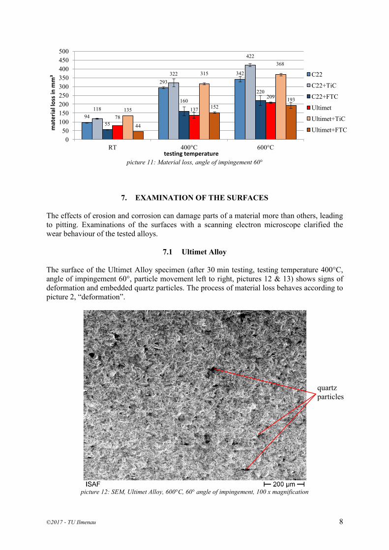
picture 11: Material loss, angle of impingement 60°
7. EXAMINATION OF THE SURFACES
The effects of erosion and corrosion can damage parts of a material more than others, leading
to pitting. Examinations of the surfaces with a scanning electron microscope clarified the
wear behaviour of the tested alloys.
7.1 Ultimet Alloy
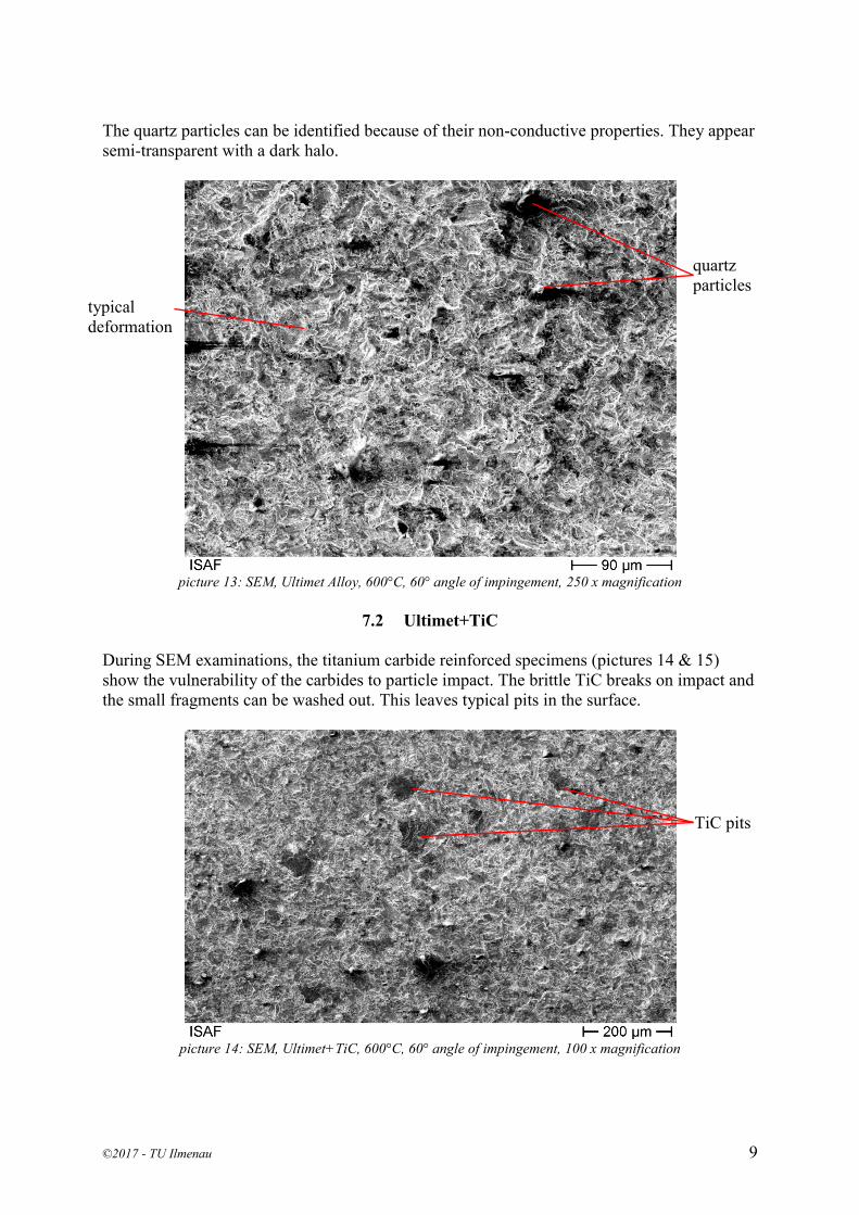
The surface of the Ultimet Alloy specimen (after 30 min testing, testing temperature 400°C,
angle of impingement 60°, particle movement left to right, pictures 12 & 13) shows signs of
deformation and embedded quartz particles. The process of material loss behaves according to
picture 2, “deformation”.
picture 12: SEM, Ultimet Alloy, 600°C, 60° angle of impingement, 100 x magnification
94
293
342
118
322
422
55
160
220
78
137
209
135
315
368
44
152
193
0
50
100
150
200
250
300
350
400
450
500
RT 400°C 600°C
mat
eri
al lo
ss in
mm
³
testing temperature
C22
C22+TiC
C22+FTC
Ultimet
Ultimet+TiC
Ultimet+FTC
quartz
particles
©2017 - TU Ilmenau 9
The quartz particles can be identified because of their non-conductive properties. They appear
semi-transparent with a dark halo.
picture 13: SEM, Ultimet Alloy, 600°C, 60° angle of impingement, 250 x magnification
7.2 Ultimet+TiC
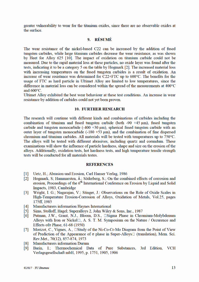
During SEM examinations, the titanium carbide reinforced specimens (pictures 14 & 15)
show the vulnerability of the carbides to particle impact. The brittle TiC breaks on impact and
the small fragments can be washed out. This leaves typical pits in the surface.
picture 14: SEM, Ultimet+TiC, 600°C, 60° angle of impingement, 100 x magnification
quartz
particles
typical
deformation
TiC pits

©2017 - TU Ilmenau 10
With greater magnification, the structure in these pits can be observed clearer. The observable
structure consists only of sharp edges and lines, while the material around the pits shows
mainly deformed edges.
picture 15: SEM, Ultimet+TiC, 600°C, 60° angle of impingement, 250 x magnification
7.3 Ultimet+FTC
Contrary to the behaviour of TiC, the fused tungsten carbide does not shatter on impact.
picture 16: SEM, Ultimet+TiC, RT, 60° angle of impingement, 250 x magnification
After tests at room temperature (picture 16) the FTC are well observable. These hard particles
stick out of the surface, and their edges are sharp.
TiC pits
FTC

©2017 - TU Ilmenau 11
The influence of the temperature is shown after tests at 400°C (picture 17). The carbide
particles appear to be flatter and with softer edges.
picture 17: SEM, Ultimet+FTC, 400°C, 60° angle of impingement, 200 x magnification
picture 18:SEM, Ultimet+FTC, 400°C, 60° angle of impingement, 250 x magnification
After the tests at 600°C, the FTC particles at the surface are completely flattened (picture 18).
The difference in wear resistance is a result of high temperature oxidation and the properties
of the tungsten oxides.
FTC
FTC

©2017 - TU Ilmenau 12
8. LIGHT MICROSCOPIC EXAMINATIONS
To explain the high wear resistance of Ultimet Alloy at high temperatures, a light microscopic
examination was conducted on a specimen after the test at 600°C (picture 19).
picture 19: Ultimet Alloy, 600°C, 60° angle of impingement, 200 x magnification, Beraha II
After the treatment with Beraha II, light spots appeared. A brighter color indicates a higher
content of alloying elements. White or bright yellow can indicate σ-phases. The small bright
spots in picture 19 are most likely σ-phases, which typically build at temperatures above
600°C. Furthermore, the expected increase in hardness of the specimen was measured. The
specimen without heat treatment showed a hardness of 265 HV10. After the 30min of testing
at 600°C, the hardness was measured at 290 HV10. A further increase of material hardness is
expected for longer times of exposition to temperatures between 600°C and 900°C. Contrary
to that, the hardness of C22 dropped from 276 HV10 to 240 HV10 after the same testing
conditions.
picture 20: C22+TiC, 600°C, 60° angle of impingement, 200 x magnification,
The near-surface titanium carbide particles (picture 20) are damaged by the impacts even with
a thin metal layer in between impacting and embedded particle. This examination indicates a
σ-phases
©2017 - TU Ilmenau 13
greater vulnerability to wear for the titanium oxides, since there are no observable oxides at the surface.
9. RÉSUMÉ The wear resistance of the nickel-based C22 can be increased by the addition of fused tungsten carbides, while large titanium carbides decrease the wear resistance, as was shown by Heet for Alloy 625 [10]. The impact of oxidation on titanium carbide could not be measured. Due to the rapid material loss at these particles, no oxide layer was found after the tests, indicating it to be a category 5 on the table by Hogmark [2]. The increased material loss with increasing temperatures on the fused tungsten carbides is a result of oxidation. An increase of wear resistance was determined for C22+FTC up to 600°C. The benefits for the usage of FTC as hard particle in Ultimet Alloy are limited to low temperatures, since the difference in material loss can be considered within the spread of the measurements at 400°C and 600°C. Ultimet Alloy exhibited the best wear behaviour at these test conditions. An increase in wear resistance by addition of carbides could not yet been proven.
10. FURTHER RESEARCH The research will continue with different kinds and combinations of carbides including the combination of titanium and fused tungsten carbide (both -90 +45 µm), fused tungsten carbide and tungsten monocarbide (-400 +30 µm), spherical fused tungsten carbide with an outer layer of tungsten monocarbide (-180 +53 µm), and the combination of fine dispersed chromium and titanium carbides. All materials will be tested with temperatures up to 750°C. The alloys will be tested with different abrasives, including quartz and corundum. These examinations will show the influence of particle hardness, shape and size on the erosion of the alloys. Additionally, oxidation tests, hot hardness tests, and high temperature tensile strength tests will be conducted for all materials testes.
REFERENCES [1] Uetz, H.; Abrasion und Erosion, Carl Hanser Verlag, 1986 [2] Hogmark, S; Hammarsten, .; Söderberg, S.; On the combined effects of corrosion and
erosion, Proceedings of the 6th International Conference on Erosion by Liquid and Solid Impacts, 1983, Cambridge
[3] Wright, I. G.; Nagarajan, V.; Stinger, J.: Observations on the Role of Oxide Scales in High-Temperature Erosion-Corrosion of Alloys, Oxidation of Metals, Vol.25, pages 175ff, 1985
[4] Manufacturers information Haynes International [5] Sims, Stolloff, Hagel; Superalloys 2, John Wiley & Sons, Inc., 1987 [6] Putman, J.W., Grant, N.J., Bloom, D.S., “Sigma Phase in Chromium-Molybdenum
Alloys with Iron or Nickel”, A. S. T. M. Symposium on the Nature / Occurence and Effects ofσ Phase, 61-68 (1950)
[7] Morizot, C., Vignes, A., “Study of the Ni-Co-Cr-Mo Diagram from the Point of View of Prediction of the Appearance of σ phase in Super-Alloys” (translation), Mem. Sci. Rev.Met., 70(12), 857-874, 1973
[8] Manufacturers information Durum [9] Barin, I.; Thermochemical Data of Pure Substances, 3rd Edition, VCH
Verlagsgesellschaft mbH, 1995, p. 1751, 1905, 1906

©2017 - TU Ilmenau 14
[10] Christian Heet; Hochtemperaturstrahlverschleißuntersuchungen an einphasigen und
mehrphasigen metallischen Werkstoffen; Papierflieger Verlag GmbH; 2015
CONTACTS
Prof. Dr.-Ing. Volker Wesling [email protected]
Dr.-Ing. Rolf Reiter [email protected]
Dr.-Ing. Jens Hamje [email protected]
Dipl.-Ing. Thomas Müller [email protected]
Related Documents