University of Central Florida University of Central Florida STARS STARS Electronic Theses and Dissertations, 2004-2019 2006 High Speed Turbo Tcm Ofdm For Uwb And Powerline System High Speed Turbo Tcm Ofdm For Uwb And Powerline System Yanxia Wang University of Central Florida Part of the Electrical and Electronics Commons Find similar works at: https://stars.library.ucf.edu/etd University of Central Florida Libraries http://library.ucf.edu This Doctoral Dissertation (Open Access) is brought to you for free and open access by STARS. It has been accepted for inclusion in Electronic Theses and Dissertations, 2004-2019 by an authorized administrator of STARS. For more information, please contact [email protected]. STARS Citation STARS Citation Wang, Yanxia, "High Speed Turbo Tcm Ofdm For Uwb And Powerline System" (2006). Electronic Theses and Dissertations, 2004-2019. 875. https://stars.library.ucf.edu/etd/875

Welcome message from author
This document is posted to help you gain knowledge. Please leave a comment to let me know what you think about it! Share it to your friends and learn new things together.
Transcript

University of Central Florida University of Central Florida
STARS STARS
Electronic Theses and Dissertations, 2004-2019
2006
High Speed Turbo Tcm Ofdm For Uwb And Powerline System High Speed Turbo Tcm Ofdm For Uwb And Powerline System
Yanxia Wang University of Central Florida
Part of the Electrical and Electronics Commons
Find similar works at: https://stars.library.ucf.edu/etd
University of Central Florida Libraries http://library.ucf.edu
This Doctoral Dissertation (Open Access) is brought to you for free and open access by STARS. It has been accepted
for inclusion in Electronic Theses and Dissertations, 2004-2019 by an authorized administrator of STARS. For more
information, please contact [email protected].
STARS Citation STARS Citation Wang, Yanxia, "High Speed Turbo Tcm Ofdm For Uwb And Powerline System" (2006). Electronic Theses and Dissertations, 2004-2019. 875. https://stars.library.ucf.edu/etd/875
HIGH SPEED TURBO TCM OFDM
FOR UWB AND POWERLINE
SYSTEM
by
YANXIA WANGB.S. Wuhan Technical University of S & M, P. R. China, 1993M.S. Wuhan Technical University of S & M, P. R. China, 1996
M.S. University of Central Florida, 2001
A dissertation submitted in partial fulfillment of the requirementsfor the degree of Doctor of Philosophy
in the School of Electrical Engineering and Computer Sciencein the College of Engineering and Computer Science
at the University of Central FloridaOrlando, Florida
Spring Term2006
Major Professor: Lei Wei

ABSTRACT
Turbo Trellis-Coded Modulation (TTCM) is an attractive scheme for higher data
rate transmission, since it combines the impressive near Shannon limit error correct-
ing ability of turbo codes with the high spectral efficiency property of TCM codes.
We build a punctured parity-concatenated trellis codes in which a TCM code is used
as the inner code and a simple parity-check code is used as the outer code. It can be
constructed by simple repetition, interleavers, and TCM and functions as standard
TTCM but with much lower complexity regarding real world implementation. An
iterative bit MAP decoding algorithm is associated with the coding scheme.
Orthogonal Frequency Division Multiplexing (OFDM) modulation has been a
promising solution for efficiently capturing multipath energy in highly dispersive chan-
nels and delivering high data rate transmission. One of UWB proposals in IEEE
P802.15 WPAN project is to use multi-band OFDM system and punctured convolu-
tional codes for UWB channels supporting data rate up to 480Mb/s. The HomePlug
Networking system using the medium of power line wiring also selects OFDM as the
ii

modulation scheme due to its inherent adaptability in the presence of frequency se-
lective channels, its resilience to jammer signals, and its robustness to impulsive noise
in power line channel. The main idea behind OFDM is to split the transmitted data
sequence into N parallel sequences of symbols and transmit on different frequencies.
This structure has the particularity to enable a simple equalization scheme and to
resist to multipath propagation channel. However, some carriers can be strongly at-
tenuated. It is then necessary to incorporate a powerful channel encoder, combined
with frequency and time interleaving.
We examine the possibility of improving the proposed OFDM system over UWB
channel and HomePlug powerline channel by using our Turbo TCM with QAM con-
stellation for higher data rate transmission. The study shows that the system can
offer much higher spectral efficiency, for example, 1.2 Gbps for OFDM/UWB which
is 2.5 times higher than the current standard, and 39 Mbps for OFDM/HomePlug1.0
which is 3 times higher than current standard. We show several essential requirements
to achieve high rate such as frequency and time diversifications, multi-level error pro-
tection. Results have been confirmed by density evolution. The effect of impulsive
noise on TTCM coded OFDM system is also evaluated. A modified iterative bit MAP
decoder is provided for channels with impulsive noise with different impulsivity.
iii

ACKNOWLEDGMENTS
First of all, I would like to express gratitude to my advisor, Dr. Lei Wei, for his
intensive supervision and critical discussion. Without his support and inspiration,
this dissertation would likely not have matured. I am very grateful to my committee
members for valuable suggestion and helpful assistance on this work.
Acknowledgement is also due my colleagues and friends in UCF, Burak for provid-
ing me the UWB channel data, Libo for successful teamwork and endless help with
the simulation, Chuanzhao and Yanhua for extremely valuable assistance in many
aspects of my life in UCF, and many others. I am very lucky to know of and work
with these wonderful persons.
Special thanks go to my parents, siblings and their families for untiring support
and seemingly unlimited belief in me. Their encouragement behind the scene keeps
pushing me forward.
Particular mention goes to my husband for improving on my best by doing his best
and my daughter for the beyond age care and consideration for her school mommy.
iv

TABLE OF CONTENTS
LIST OF FIGURES xi
LIST OF TABLES xii
I CHAPTER I INTRODUCTION 1
1.1 Background and Motivation . . . . . . . . . . . . . . . . . . . . . . . 1
1.2 Thesis Outline . . . . . . . . . . . . . . . . . . . . . . . . . . . . . . . 6
1.3 Contributions . . . . . . . . . . . . . . . . . . . . . . . . . . . . . . . 8
1.4 Paper List . . . . . . . . . . . . . . . . . . . . . . . . . . . . . . . . . 10
II CHAPTER II LITERATURE REVIEW 11
2.1 Trellis Coded Modulation . . . . . . . . . . . . . . . . . . . . . . . . 11
2.1.1 Ungerboeck’s Trellis-coded Modulation . . . . . . . . . . . . . . 12
2.1.2 Multi-dimensional TCM . . . . . . . . . . . . . . . . . . . . . 15
2.1.3 Forney’s Concatenated TCM . . . . . . . . . . . . . . . . . . 21
v

2.2 Turbo Codes . . . . . . . . . . . . . . . . . . . . . . . . . . . . . . . . 22
2.3 Turbo Trellis Coded Modulation . . . . . . . . . . . . . . . . . . . . . 28
2.3.1 Binary Turbo Coded Modulation . . . . . . . . . . . . . . . . . 29
2.3.2 Symbol interleaved Turbo TCM . . . . . . . . . . . . . . . . . 30
2.3.3 Bit interleaved Turbo TCM . . . . . . . . . . . . . . . . . . . 32
2.4 Multicarrier Modulation and OFDM . . . . . . . . . . . . . . . . . . 34
2.4.1 Data Transmission Using Multicarriers . . . . . . . . . . . . . 36
2.4.2 Mitigation of Subcarrier Fading . . . . . . . . . . . . . . . . . 40
2.4.3 Discrete Implementation of Multicarrier . . . . . . . . . . . . 42
IIICHAPTER III TTCM OFDM SYSTEM FOR UWB CHANNELS 51
3.1 OFDM System For UWB Channel . . . . . . . . . . . . . . . . . . . 55
3.1.1 16QAM Turbo TCM Encoder Structure . . . . . . . . . . . . . 56
3.1.2 16QAM Gray Mapping . . . . . . . . . . . . . . . . . . . . . . 63
3.1.3 OFDM Modulation . . . . . . . . . . . . . . . . . . . . . . . . 66
3.1.4 UWB Channel . . . . . . . . . . . . . . . . . . . . . . . . . . 70
3.1.5 CP-OFDM Equalization . . . . . . . . . . . . . . . . . . . . . 75
3.2 Modified Iterative Bit MAP Decoding . . . . . . . . . . . . . . . . . . 80
3.3 System Performance Analysis . . . . . . . . . . . . . . . . . . . . . . 87
3.3.1 Density Evolution for TTCM . . . . . . . . . . . . . . . . . . 87
3.3.2 Bound Performance for TTCM . . . . . . . . . . . . . . . . . 94
vi

3.4 Numerical Results . . . . . . . . . . . . . . . . . . . . . . . . . . . . . 98
3.4.1 640Mbps OFDM System Over UWB Channel . . . . . . . . . 100
3.4.2 1.2Gbps OFDM System Over UWB Channel . . . . . . . . . . 103
IV CHAPTER IV TTCM OFDM SYSTEM FOR POWERLINE CHAN-
NELS 106
4.1 Introduction of Powerline Communications . . . . . . . . . . . . . . . 106
4.2 OFDM System For Power Line Channel . . . . . . . . . . . . . . . . 110
4.2.1 64QAM Parity-concatenated TCM Encoder . . . . . . . . . . 111
4.2.2 64QAM Gray Mapping . . . . . . . . . . . . . . . . . . . . . . 118
4.2.3 OFDM Modulation . . . . . . . . . . . . . . . . . . . . . . . . 118
4.2.4 Power Line Channel . . . . . . . . . . . . . . . . . . . . . . . 123
4.2.5 ZP-OFDM Equalization . . . . . . . . . . . . . . . . . . . . . 126
4.3 Numerical Results . . . . . . . . . . . . . . . . . . . . . . . . . . . . . 131
V CHAPTER V TTCM OFDM SYSTEM FOR IMPULSIVE NOISE
CHANNEL 134
5.1 System and Channel Model . . . . . . . . . . . . . . . . . . . . . . . 135
5.2 Modified Iterative Bit MAP Decoder . . . . . . . . . . . . . . . . . . 137
5.3 Numerical Results . . . . . . . . . . . . . . . . . . . . . . . . . . . . . 138
5.4 Summary . . . . . . . . . . . . . . . . . . . . . . . . . . . . . . . . . 142
vii

VI CHAPTER VI CONCLUSION 143
6.1 Summary of Results . . . . . . . . . . . . . . . . . . . . . . . . . . . 143
6.2 Further Research . . . . . . . . . . . . . . . . . . . . . . . . . . . . . 146
LIST OF REFERENCES 164
viii

LIST OF FIGURES
2.1 General structure of encoder / modulator for trellis-coded modulation. 12
2.2 Partitioning of 8-PSK channel signals into subsets . . . . . . . . . . . 13
2.3 Set partition and trellis representation of a trellis code . . . . . . . . 14
2.4 Two encoder for a linear 8-state convolutional code . . . . . . . . . . 15
2.5 192-point 2D constellation partitioned into four subsets . . . . . . . . 17
2.6 Set partitioning of 4D lattice . . . . . . . . . . . . . . . . . . . . . . . 17
2.7 16-state code with 4-D rectangular constellation . . . . . . . . . . . . 19
2.8 Viterbi decoding algorithm for 16-state code of Figure 2.7 . . . . . . . 20
2.9 Forney’s concatenated coding system . . . . . . . . . . . . . . . . . . 22
2.10 Basic turbo encoder (rate 1/3) . . . . . . . . . . . . . . . . . . . . . . 23
2.11 Principle of the decoder in accordance with a serial concatenated scheme 24
2.12 Feedback decoder for turbo codes . . . . . . . . . . . . . . . . . . . . 27
2.13 Multilevel turbo encoder . . . . . . . . . . . . . . . . . . . . . . . . . 29
2.14 Turbo TCM encoder with parity symbol puncturing . . . . . . . . . . 31
ix

2.15 Trubo trellis-coded modulation, 16 QAM, 2bits/s/Hz . . . . . . . . . 33
2.16 Multicarrier transmitter. . . . . . . . . . . . . . . . . . . . . . . . . . 38
2.17 Transmitted signal. . . . . . . . . . . . . . . . . . . . . . . . . . . . . 38
2.18 Multicarrier receiver. . . . . . . . . . . . . . . . . . . . . . . . . . . . 40
2.19 Cyclic prefix of length µ. . . . . . . . . . . . . . . . . . . . . . . . . . 45
2.20 ISI between data blocks in channel output. . . . . . . . . . . . . . . . 47
2.21 OFDM with IFFT/FFT implementation. . . . . . . . . . . . . . . . . 50
3.1 Block diagram of coded OFDM system. . . . . . . . . . . . . . . . . . 54
3.2 Parity-concatenated TCM encoder, 16QAM . . . . . . . . . . . . . . 59
3.3 Expansion from Benedetto’s TTCM to parity-concatenated TCM . . 60
3.4 16QAM constellation . . . . . . . . . . . . . . . . . . . . . . . . . . . 65
3.5 Subcarrier frequency allocation . . . . . . . . . . . . . . . . . . . . . 68
3.6 Example frequency response of a good UWB channel. . . . . . . . . . 73
3.7 Example frequency response of a bad UWB channel. . . . . . . . . . 74
3.8 Discrete-time block equivalent model of CP-OFDM. . . . . . . . . . . 76
3.9 Iterative (turbo) decoder structure for two trellis codes . . . . . . . . 86
3.10 Block diagram of the iterative decoder. . . . . . . . . . . . . . . . . . 86
3.11 Density evolution for 16QAM/OFDM on AWGN and UWB channels. 91
3.12 Density evolution for 64QAM/OFDM on AWGN and UWB channels. 93
3.13 Bounds on BER for systems with N = 10. . . . . . . . . . . . . . . . 97
x

3.14 BER of OFDM/16QAM over UWB and AWGN channel. . . . . . . . 101
3.15 PER of OFDM/16QAM over UWB and AWGN channel. . . . . . . . 102
3.16 BER of OFDM/64QAM over UWB and AWGN channel. . . . . . . . 104
3.17 PER of OFDM/64QAM over UWB and AWGN channel. . . . . . . . 105
4.1 Parity-concatenated TCM encoder, 64QAM . . . . . . . . . . . . . . 112
4.2 Turbo TCM encoder, 64QAM . . . . . . . . . . . . . . . . . . . . . . 113
4.3 Bit interleaver . . . . . . . . . . . . . . . . . . . . . . . . . . . . . . . 116
4.4 Interleaved data on first 4 symbols . . . . . . . . . . . . . . . . . . . 117
4.5 64QAM constellation . . . . . . . . . . . . . . . . . . . . . . . . . . . 119
4.6 Impulse response of power line channel. . . . . . . . . . . . . . . . . . 124
4.7 Frequency response of power line channel. . . . . . . . . . . . . . . . 125
4.8 Discrete-time block equivalent model of ZP-OFDM. . . . . . . . . . . 127
4.9 BER of OFDM/64QAM over power line and AWGN channel. . . . . 132
4.10 PER of OFDM/64QAM over power line and AWGN channel. . . . . . 133
5.1 BER of OFDM/64QAM over memoryless channe . . . . . . . . . . . 140
5.2 BER of OFDM/64QAM over UWB channel . . . . . . . . . . . . . . 141
xi

LIST OF TABLES
2.1 Eight sublattice partitioning of 4D rectangular lattice . . . . . . . . 18
3.1 Mappings for each dimension of 16QAM . . . . . . . . . . . . . . . . 64
3.2 Coded OFDM system parameters . . . . . . . . . . . . . . . . . . . . 99
4.1 Mappings for each dimension of 64QAM . . . . . . . . . . . . . . . . 118
4.2 HomePlug 1.0 OFDM Specifications . . . . . . . . . . . . . . . . . . . 122
xii
CHAPTER I
INTRODUCTION
1.1 Background and Motivation
Information transferred within an electronic communication channel is always li-
able to be corrupted by noise within the channel. The need therefore arises to be able
to preserve information accurately as it journeys through a noisy channel. Address-
ing this problem, Shannon [1] in 1948, showed that arbitrarily reliable transmission
is possible through the noisy channel if the information rate in bits per channel use
is less than the channel capacity of the channel. Furthermore, Shannon et al. proved
the existence of codes that enable information to be transmitted through a noisy
channel such that the probability of errors is as small as required, providing that the
transmission rate dose not exceed the channel capacity. This is now known as the
channel coding theorem. The codes referred to in the channel coding theorem do not
1

prevent the occurrence of errors, but rather allow their presence to be detected and
corrected. These codes are known as error-detecting and error-correcting codes, or in
short error-control codes.
In today’s telecommunications market there are dramatically increasing demands
for capacity, high data rates, service diversity, and service quality, which have to be
achieved with spectrum utilization efficiency and low complexity of technologies. The
error control coding plays a key role in the design of such digital communications sys-
tems. The aim of the error control is to ensure that the received information is as
close as possible to the transmitted information, with as low as possible complexity.
A well known result from Information Theory is that a randomly chosen code of suf-
ficiently large block length is capable of approaching channel capacity [1]. However,
the optimal decoding complexity increases exponentially with block length up to a
point where decoding becomes physically unrealizable. Much of communications and
coding research has been driven by the problem of efficient data communications over
transmission medium impaired by noise and interference over the past half century.
As the landmark developments in coding area, the invention of turbo error control
codes [2] and the rediscovery of low-density parity-check (LDPC) codes [3] [4] have
created tremendous excitement since the gap between the Shannon capacity limit
and practically feasible channel utilization is essentially closed. Since then, much
attention has been drawn to theoretically understand the essence of turbo codes
and LDPC codes. Motivated by the principle of turbo codes, researchers have come
2

up with many compound codes, such as: serially concatenated codes [5], parallel
concatenated codes [6] [7], various product code [8], Turbo Trellis-coded Modula-
tion (TTCM) [9] [10] [11] [12] [13] [14], multilevel codes [15] [16] [17], and parity-
concatenated codes [18] [19] [20]. Among aforementioned compound codes, TTCM is
an attractive scheme for higher data rate transmission, since it combines the impres-
sive near shannon limit error correcting ability of turbo codes with the high spectral
efficiency property of TCM.
Motivated by [18] [19], which concatenate convolutional codes with low-density
parity-check codes and obtain the performance within 0.45 dB of the Shannon limit,
we explore the concatenation of trellis-coded modulation with low-density parity-
check codes and build the corresponding decoding structure. The objective is to
develop a novel coding/decoding scheme suitable for current or desired communica-
tion systems with superior bit error rate performance over existing systems at a high
bandwidth efficiency with low complexity.
Digital multimedia applications as they are getting common lately create an ever
increasing demand for broad band communication systems. Ultra-wideband (UWB)
communications has received great interest from the research community and industry
due to its potential strength of leveraging extremely wide transmission bandwidths,
to produce such desirable capabilities as extremely high data rate at short ranges,
accurate position location and ranging, immunity to significant fading, high multiple
access capability and potentially easier material penetrations [21] [22] [23] [24] [25].
3
It is essential for a wireless system to deal with the existence of multiple propagation
paths (multipath) exhibiting different delays, resulting from objects in the environ-
ment causing multiple reflections on the way to the receiver. The large bandwidth
of UWB waveforms significantly increases the ability of the receiver to resolve the
different reflections in the channel [26] [27] [28] [29] [30]. Two basic solutions for
inter-symbol interference (ISI) caused by multi-path channels are equalization and
orthogonal frequency-division multiplexing (OFDM) [31] [32] [33].
In February 2002, the Federal Communications Commission allocated 7400 /MHz
of spectrum for unlicensed use of commercial ultra-wideband (UWB) communication
applications in the 3.1-10.6GHz frequency band. This move has initiated an extreme
productive activity for industry and academic. Because of the restrictions on the
transmit power, UWB communications are best suited for short-range communica-
tions: sensor networks and personal area networks (PANs). For highly dispersive
channels like UWB, an orthogonal frequency- division multiplexing (OFDM) scheme
is more efficient at capturing multipath energy than an equivalent single-carrier sys-
tem using the same total bandwidth [34] [35] [36] [37] [38]. OFDM systems posses
additional desirable properties, such as high spectral efficiency, inherent resilience to
narrow-band RF interface and spectrum flexibility. IEEE P802.15 WPAN project [39]
proposed a multiband OFDM system for UWB channel with data rate up to 480Mb/s
by using punctured convolutional codes. We try to improve the system by using our
TTCM functional parity-concatenated TCM code for offering much higher spectral
4

efficiency when used in OFDM systems over UWB channel.
Increasing interest in smart home automation or home networks has driven the
use of the low voltage power line as a high speed data channel. Powerline communica-
tions stands for the use of power supply grid for communication purpose. Power line
network has very extensive infrastructure in nearly each building. Because of that
fact the use of this network for transmission of data in addition to power supply has
gained a lot of attention. Since power line was devised for transmission of power at
50-60 Hz and at most 400 Hz, the use this medium for data transmission, at high fre-
quencies, presents some technically challenging problems. Besides large attenuation,
power line is one of the most electrically contaminated environments, which makes
communication extremely difficult. Further more the restrictions imposed on the use
of various frequency bands in the power line spectrum limit the achievable data rates.
OFDM has been chosen as the modulation technique in Home Plug systems for
high speed networking using the medium of power line wiring because of its inherent
adaptability in the presence of frequency selective channels, its resilience to jammer
signals, and its robustness to impulsive noise in power line channel. Again, we are
trying to implement our parity-concatenated TCM coding/decoding scheme onto the
current Home Plug system for offering higher data rate over power line channel.
5

1.2 Thesis Outline
The thesis is organized as follows. Chapter II first gives a technical review of pre-
vious work on TCM coding schemes, such as Ungerboeck’s TCM [40] [41] [42], multi-
dimensional TCM [16] [43] [44] [45], and Forney’s concatenated TCM [46], followed
by the description of the existed parity-concatenated TCM codes by [18] [19] [20].
As a natural extension of binary turbo codes, several turbo trellis coded modulation
(TTCM) schemes have been developed for bandwidth-limited communications sys-
tems, and the remarkable error performance close to the Shannon capacity limit has
been achieved. The corresponding decoding algorithms for coding schemes mentioned
above will be explored thereafter, which will help build the iterative decoding scheme
for our TTCM-functional parity-concatenated TCM codes in chapter III. Then, the
principle of multicarrier modulation (MCM) will be highlighted and some notation
specifically defined for MCM system will be introduced in this chapter for easy de-
scription in later chapters.
In chapter III, the architecture for UWB system based on multiband OFDM in
IEEE P802.15 WPAN project proposal will be introduced first. Since our concern is
the performance of the coded OFDM system, we follow the OFDM architecture in the
standards and replace the punctured convolutional coding in standard by our parity-
concatenated TCM codes. Then we will illustrate our proposed parity-concatenated
TCM encoding structure, which is constructed by a punctured parity-concatenated
6

trellis codes in which a TCM code is used as the inner code and a simple parity-check
code is used as the outer code. It functions as turbo TCM and has potential for
offering much higher spectral efficiency when used in OFDM systems. The detailed
advantage of our encoding scheme over Benedetto’s TTCM structure, such as how it
functions as Turbo TCM, how it saves constituent codes and interleavers of conven-
tional TTCM and how to extend the simple encoder structure to more complicated
parity-concatenated TCM for coding rate diversity will be given sequentially. The
corresponding iterative decoding algorithm extended from the standard binary turbo
codes for our parity-concatenated TCM codes will be illustrated thereafter.
Then we will focus on the application performance of this Turbo TCM codes in
OFDM system over UWB channel. We show several essential requirements to achieve
high rate such as frequency and time diversifications, multi-level error protection and
etc. OFDM modulation, UWB channel model, OFDM symbols passing through UWB
channel, equalization at the receiver, information recovery and system performance
evaluation through density evolution will all be elaborated in this chapter.
Chapter IV presents performance of our proposed Turbo TCM codes when applied
to the HomePlug System. The HomePlug Power Line Networking system is specified
only for operation on residential AC power lines carrying nominal AV voltages from
120 V to 240 V. The powerline channel characteristics, OFDM modulation scheme,
interleaver design will be covered in this chapter. We replace the convolutional codes
in forward error correction (FEC) part specified in the standard by our turbo TCM
7

encoder and evaluate the system’s performance through simulation over measured 60
feet powerline channel.
Chapter V illustrates the effect of impulsive noise on the TTCM coded OFDM
system. The impulsive noise is an additive disturbance that arises primarily from the
switching electric equipment. Therefore, bursty or isolated errors are usually gener-
ated by an impulsive noise affecting consecutive symbols in the trellis-based decoding
algorithms since such decoders heavily rely on the history of the symbol sequence. We
evaluate the system performance suffering impulsive noise with different impulsivity
by modifying our iterative bit MAP decoding algorithm.
Finally in chapter VI, a brief summary of the accomplished work is presented
followed by the discussion of further research in this area.
1.3 Contributions
The key contributions of this thesis are summarized below:
(1) Parity-concatenated TCM scheme, which functions as a Turbo TCM and gain
several advantages over the conventional TTCM, is proposed; (chapter III)
(2) A robust iterative Bit MAP decoding algorithm is developed for the proposed
parity-concatenated TCM. The superior performance can be achieved; (chapter
III)
8

(3) The proposed parity-concatenated TCM is applied to OFDM/UWB system,
which improves the UWB proposals in IEEE P802.15 WPAN project by offering
much higher spectral efficiency. The real world application is suggested; (chapter
III)
(4) Performance evaluation for turbo TCM using union bound is explored with a
new method for computing the error weight distribution for turbo TCM codes;
(chapter III)
(5) The performance of proposed parity-concatenated TCM scheme and iterative
decoding algorithm is confirmed by density evolution; (chapter III)
(6) The proposed parity-concatenated TCM is applied to OFDM/HomePlug system,
which improves the Home Plug system by offering higher spectral efficiency and
better performance. The real world application is also suggested; (chapter IV)
(7) The performance of TTCM coded OFDM system suffering impulsive noise in
different channels with different impulsivity is evaluated. The iterative bit MAP
algorithm is modified to match the statistical property of the impulsive noise.
(chapter V)
9

1.4 Paper List
(1) Y. Wang, L.Yang, and L.Wei, High Speed Turbo Coded OFDM System For
UWB Channels, 2005 IEEE International Symposium on Information Theory
(ISIT 2005), Sept. 4-5, 2005, Adelaide, Australia.
(2) Y. Wang, L. Yang, and L.Wei, Turbo TCM Coded OFDM System For Powerline
Channel, Turbo-coding 2006, Apr. 3-7, 2006, Munich, Germany.
(3) Y. Wang, L. Yang, and L. Wei, High Speed Turbo Coded OFDM UWB System,
accepted by EURASIP Journal on Wireless Commun. and Networking breakup
special issue on Ultra-Wideband (UWB) Commun. Sys. Technology and Appli-
cations.
(4) Y. Wang and L. Wei, Turbo TCM Coded OFDM Systems for Non-Gaussian
Channels, submitted to 2006 IEEE International Symposium on Information
Theory (ISIT 2006), Jul. 9-14, 2006, Seattle, USA.
(5) Y. Wang and L. Wei, High Speed Turbo TCM OFDM Powerline System, pre-
pared for journal paper submission.
(6) L. Yang, Y. Wang, and L. Wei, Turbo TCM Coded OFDM Systems for Impulsive
Noise Channel, prepared for journal paper submission.
10

CHAPTER II
LITERATURE REVIEW
2.1 Trellis Coded Modulation
Power and bandwidth are limited resources in modern communication systems,
and efficient exploitation of these resources will invariably increase the complexity of
the system. One very successful scheme of achieving significant coding gain over con-
ventional uncoded multilevel modulation without compromising bandwidth efficiency
was proposed by Ungerboeck [47] in 1976 and was subsequently termed as trellis-
coded modulation (TCM) [40] [41] [42]. TCM schemes employ redundant nonbinary
modulation in combination with a finite-state encoder which governs the selection of
modulation signals to generate coded signal sequences. In the receiver, the noisy sig-
nals are decoded by a maximum-likelihood sequence decoder. A simple 4-state TCM
scheme can achieve 3 dB gain over conventional uncoded modulation without band-
11

width expansion or reduction of the effective information transmission rate. With
more complex TCM scheme (multi-dimensional TCM), the coding gain can reach 6
dB. The most practical selection is 4-D WEI TCM scheme [44].
2.1.1 Ungerboeck’s Trellis-coded Modulation
The concept of TCM is to use signal-set expansion to provide redundancy for cod-
ing, and to design coding and signal mapping functions jointly so as to maximize the
”free distance” (minimum squared Euclidean distance –MSED) between coded sig-
nal sequences. This allows the construction of modulation codes whose free distance
significantly exceeds the minimum distance between uncoded modulation signals, at
the same information rate, bandwidth, and the signal power. Figure 2.1 depicts the
general structure of TCM encoder/modulator.
n
from subsetselect signal
select subset
n
n
~
n
n
n0
n
~
~
1encoder
Rate m/m+1~ ~
~
}
MappingSignal
n
Convolutional
kk
1
k
~
k−k
k+1
a}k
k+1
u
u
u
u
v
v
v
Figure 2.1: General structure of encoder / modulator for trellis-coded modulation.
When k bits are to be transmitted per encoder/modulator operation, k ≤ k bits
are expanded by a rate k/(k + 1) binary convolutional encoder into k + 1 coded bits.
12

These bits are used to select one of 2k+1 subsets of a redundant bits determined 2k+1-
ary signal set. The remaining k− k uncoded bits determine which of the 2k−k signals
in this subset is to be transmitted.
∆
∆
∆
����
������������
������������
����
����
����
����
����
����
����
����
����
����
����
����
����
����
����
����
����
����
����
����
����
����
������
������
����������������
����������������
A0 = 8−PSK
0
.
0 1
0
0 0 0 0
0 1
1111
����
(001) (101) (011)(000)
1
(100) (010) (110) (111)
2
B1B0
C0 C2 C1 C3
= 0.765
=1.414
= 2.000
1
����
����
Figure 2.2: Partitioning of 8-PSK channel signals into subsets with increasing mini-mum subset distances(∆0 < ∆1 < ∆2; E|a2
n| = 1).
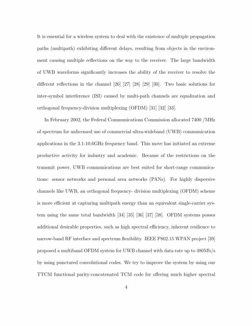
Maximizing free minimum squared Euclidean distance (MSED) is based on a map-
ping rule called ”mapping by set partitioning”. This mapping follows from successive
partitioning of a channel-signal set into subsets with increasing minimum distance
∆0 < ∆1 < ∆2... between the signals of these subsets. The partitioning is repeated
k + 1 times until ∆k+1 is equal or greater than than the desired MSED. of the TCM
to be designed. This concept is illustrated in Figure 2.2 and 2.3(a) for 8-PSK and
16-QASK modulation respectively, and is applicable to all modulation forms of Figure
2.1.
The encoding process of trellis code can be represented by the trellis diagram.
13
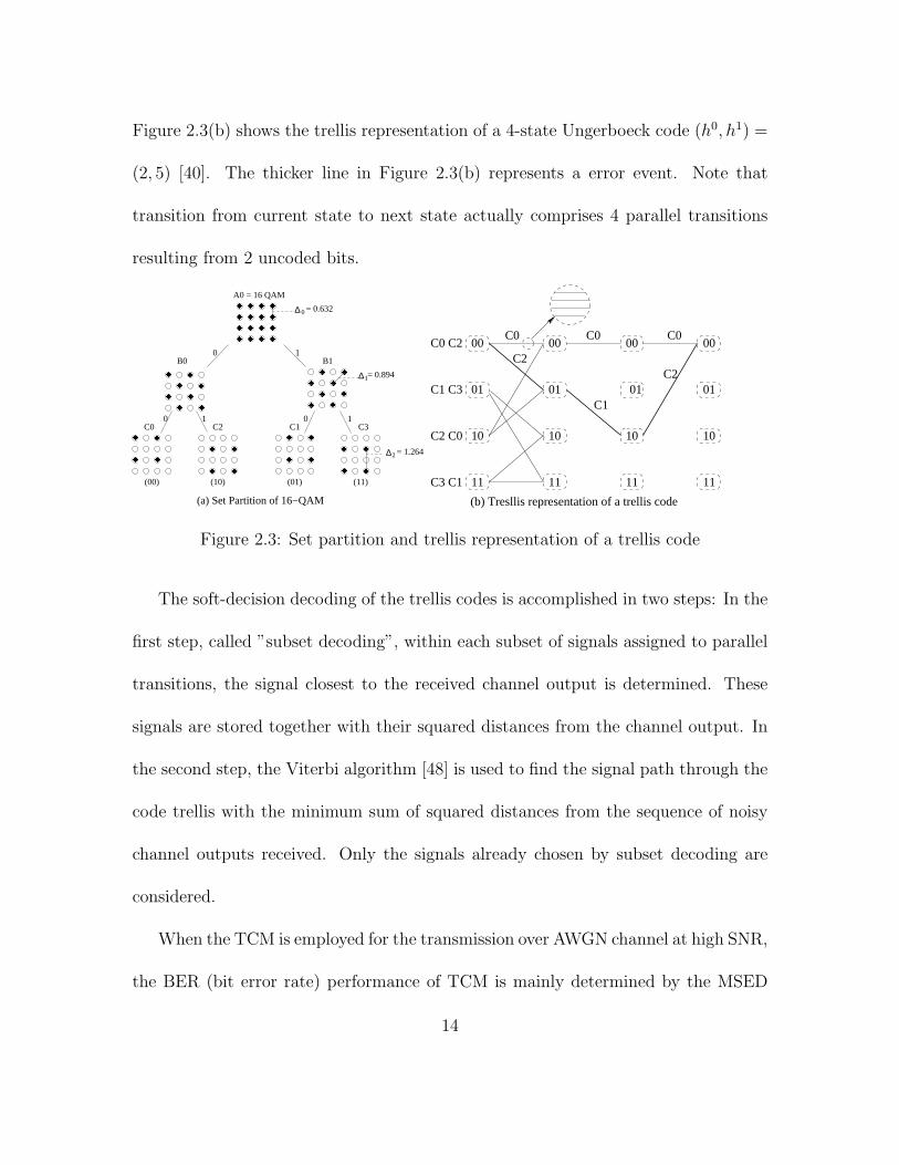
Figure 2.3(b) shows the trellis representation of a 4-state Ungerboeck code (h0, h1) =
(2, 5) [40]. The thicker line in Figure 2.3(b) represents a error event. Note that
transition from current state to next state actually comprises 4 parallel transitions
resulting from 2 uncoded bits.
∆
∆
∆
C3C2 C1
(01)(10)
C0
(00)
B0 B1
(11)
2= 1.264
0 1
0 1
10
1 = 0.894
0= 0.632
A0 = 16 QAM
(a) Set Partition of 16−QAM
����
����
����
����
����������������
����
����
����
����
����
����
����
����
��������
����
����
����
����
����
����
����
����
����
����
����
����
����
����
����
����
����
����
����
����
����
����
����
����
����
����
����
����
����
����
(b) Tresllis representation of a trellis code
00 00 00 00
01 01 01 01
10 10 10 10
11 11 11 11
C0 C2
C1 C3
C2 C0
C3 C1
C0 C0 C0
C2
C1
C2
Figure 2.3: Set partition and trellis representation of a trellis code
The soft-decision decoding of the trellis codes is accomplished in two steps: In the
first step, called ”subset decoding”, within each subset of signals assigned to parallel
transitions, the signal closest to the received channel output is determined. These
signals are stored together with their squared distances from the channel output. In
the second step, the Viterbi algorithm [48] is used to find the signal path through the
code trellis with the minimum sum of squared distances from the sequence of noisy
channel outputs received. Only the signals already chosen by subset decoding are
considered.
When the TCM is employed for the transmission over AWGN channel at high SNR,
the BER (bit error rate) performance of TCM is mainly determined by the MSED
14

d2free, which is the minimum value of the squared parallel transition distance ∆2
k+1
and the coded minimum squared Euclidean distance ∆2k, i.e., d2
free = min(∆2k+1
, ∆2k).
If ∆2k
< ∆2k+1
, we can say the BER caused by ∆2k
is dominant and ∆2k+1
can be
ignored.
D
D
D D
D D
h
n
n
n
n
nn
n2
20
0n
1
1n1
2
112
2
(b)(a)
n
u
v
v
v
u
u
v
vv
u
h1
2
Figure 2.4: Two encoder for a linear 8-state convolutional code. (a) Minimal system-atic encoder with feedback; (b)Minimal feedback-free encoder
For the encoder realizations, Figure 2.4 gives two structures. One is called a sys-
tematic encoder with feedback and the other is feedback free encoder. The forward
and backward connections in the systematic encoder are specified by the parity-check
coefficients of the code.
2.1.2 Multi-dimensional TCM
Many powerful multi-dimensional (M-D) trellis codes have been discovered due
to a number of potential advantages over the usual 2-D schemes. One of them is
the M-D Wei codes [44] [45] which have been the most attractive selection for many
applications such as the high-rate voice band modem and the ADSL modem.
Multi-dimensional signals can be transmitted as sequences of constituent one- or
15

two-dimensional signals. For instance, 2N-D TCM encoder, can be viewed as formed
by N constituent 2-D encoders. If each 2-D signal transmit k bits, then each 2N-
D signal needs to transmit Nk bits. The principle of using a redundant signal set
of twice the size needed for uncoded modulation is maintained. Thus, 2N-D TCM
schemes uses 2Nk+1 -ary sets of 2N-D signals. Compared to 2-D TCM scheme, this
results in less signal redundancy in the constituent 2-D signal sets.
Some terminology regarding the M-D set partition needs to be clarified here. A
lattice is partitioned into families, subfamilies and sublattices with strict increasing
MSED. Only the bottom level of a partitioning is referred to as sublattice. This level
will be assigned to the state transition or equivalently, specified by the output of a
trellis code.
In general, the partitioning of a 2N-D lattice may be done as follows. Suppose the
desired MSED of each 2N-D sublattice is ∆0. The first step is to partition its con-
stituent N-D lattices into families, subfamilies and sublattices with increasing MSED.
Each finer partitioning of the N-D lattice increases the MSED by a factor of two, with
the MSED of each N-D sublattice also equal to ∆0. The second step is to form 2N-
D types, each type corresponding to a concatenation of a pair of N-D sublattices.
The MSED of each 2N-D type is also ∆0. Those 2N-D types are grouped into 2N-D
sublattices with the same MSED, based on the N-D subfamilies. If there are M N-
D sublattices in each N-D subfamily, then each 2N-D sublattice comprises M 2N-D
types. M-D lattice partition is based iteratively on a partitioning of the constituent
16

b
d
cb
ad
cb
ad
cb
ad
cb
ad
cb
ad
cb
ad
cb
ad
cb
ad
cb
ad
cb
ad
cb
ad
cb
ad
cb
ad
cb
ad
cb
ad
cb
ad
cb
ad
cb
ad
cb
ad
cb
ad
cb
ad
cb
ad
cb
ad
cb
ad
cb
����
����
����
����
����
����
����
����
����
����
����
����
����
����
����
����
����
����
����
����
����
����
����
����
����
����
����
����
����
����
����
����
����
����
����
����
����
����
����
����
����
����
����
����
����
����
����
����
����
����
����
����
����
����
����
����
����
����
����
����
����
����
����
����
����
����
����
����
����
����
����
����
����
����
����
����
����
����
����
����
����
����
����
����
����
����
����
����
����
����
����
����
����
����
����
����
����
����
����
����
����
����
����
����
����
����
����
����
����
����
����
����
����
����
����
����
����
����
����
����
����
����
����
����
����
����
����
����
����
����
����
����
����
����
����
����
����
����
����
����
����
����
����
����
����
����
����
����
����
����
����
����
����
����
����
����
����
����
����
����
����
����
����
����
����
����
����
����
����
����
����
����
����
����
����
����
����
����
����
����
����
����
����
����
����
����
����
����
����
����
����
����
��������������������������������������������������������������������������������������n+1n orx x
a ad d
d
b
n+1yny or
bc
a
c
a
c
c
a
cb
ad
cb
ad
cb
ad
cb
d
cb b
d
cb
ad
cb
ad
cb
ad
cb
ad
b
a
cb
ad
cb
ad
cb
ad
cb
ad
c
a ad
c
ad
cb
ad
cb
ad
cb
ad
b
d
b
cc
da
Figure 2.5: 192-point 2D constellation partitioned into four subsets
2D lattices.
∆
∆
∆
∆
∆
10 2 3 4 765
B x B C x C
D x D A x B C x D
B x A D x B
C x B A x D B x C D x B
A x A B x D
2 2 2 2
222 2
B1 B2
MSED
2
4
4
4
0
0
0
0
0
D
D4 D4
D4D4D4D4D4D4D4D4
2
2D Sublattice
4D Type
4D Family
4D Lattice
4D Sublattice
A x C
1
21 1
1 1
1 1 2
1 2 D x A 1 2
21 1
1
1
1
C x A
4
21
21
Figure 2.6: Set partitioning of 4D lattice
To partition the 4D rectangular lattice with the MSED ∆0, into eight 4D sublat-
tices with MSED 4∆0, each constituent 2D rectangular lattice with MSED ∆0 is first
partitioned into two 2D families A ∪ B and C ∪ D with MSED 2∆0, which are further
partitioned into four 2D sublattices A,B,C,D with MSED 4∆0, as shown in Figure
17

2.5 and 2.6. Sixteen 4D types may then be defined, each corresponding to a concate-
nation of a pair of 2D sublattices, and denoted as (A,A), (A,B),..., and (D,D). The
MSED of each 4D types is 4∆0. 16 4D types can be grouped into 8 4D sublattices,
denoted as 0,1,...,7, as shown in Table 2.1. The grouping, while yielding only half as
many 4D sublattices as 4D types, is done in such a way which maintains the MSED
of each 4D sublattice at 4∆0. This kind of grouping simplifies the construction of
trellis codes using those sublattices. 8-D and 16 - D lattice partition can be easily
extended following the above partitioning rule.
Table 2.1: Eight sublattice partitioning of 4D rectangular lattice
v1
4D
(subset)
0 0n
0 0 0 0 0 00 00 0 0 00 0 0 0 00 00 0 0 0 0 00 0 0 0 00 0 00 0
0000000 0 00 0 0 00 0 0
0 0 0 00 0 0
0 0 00
0
1
2
3
7
6
5
4
11
1111
11
1111
11
1 111
1 1 11
1
1
1
1
1
1111
1 1 1
11
111
11
11 1111 1
1
1
1
111
1
1
111
11
11 1
1
(A, A)(B, B)(C, C)(D, D)(A, B)(B, A)(C, D)(D, C)(A, C)(B, D)(C, B)(D, A)(A, D)(B, C)(C, A)(D, B)
’ ’Sublatticen n n+1 n+1nnny0 u1 u2 u3 v0 v1 v04D Types
In [44], Wei has constructed several M-D trellis codes with 4-D and 8-D constella-
tion. One of them is the well known 4-D 16-state Wei trellis codes. Figure 2.7 shows
the encoder structure for this code.
During encoding process, two 2-D symbols are simultaneously inputted into a 4-D
trellis encoder at every two successive time intervals n, n+1. Three bits are encoded
through trellis encoder after a differential encoder, while the rest bits in two 2-D
18
2D
BIT
CO
NV
ER
TE
RDIFFERENTIALENCODER
MA
PP
ER
Uncoded Bits
TW
O 2
−D
SY
MB
OLS
n
n
n+1
n+1
n
n
n
n
n
n
n
Trellis Encoder
u3
u2
u1
u3
u2
u1
y0
v1
v0
v1
v0
2D 2D 2D
Figure 2.7: 16-state code with 4-D rectangular constellation
symbols remain uncoded. In the Wei code design, three of those uncoded bits are en-
coded via a 4-D block encoder which actually implements the shell mapping presented
in [49]. Four output bits Y0n, I1n, I2n’, and I2n’ are then converted by a bit converter
to produce two groups of coded bits which correspond to a 2-D sub-constellations
in one 4-D trellis code comprising two 2-D trellis codes. In the receiver, the VA is
applied to decode received 4-D signals. The only difference with decoding the 2-D
trellis codes is the calculation of branch metrics for 4-D subsets.
A conventional maximum-likelihood decoding algorithm such as Viterbi algorithm
is used as the decoder for TCM codes. First, the decoder must determine the point
in each of the M-D subsets which is closest to the received point, and calculate its
associated metric (the squared Euclidean distance between the two points). Each
received 2N-D point is divided into a pair of N-D points. The closest point in each
2N-D subset and its associated metric are found based on the point in each of the N-D
subsets which is closest to the corresponding received N-D point and its associated
19
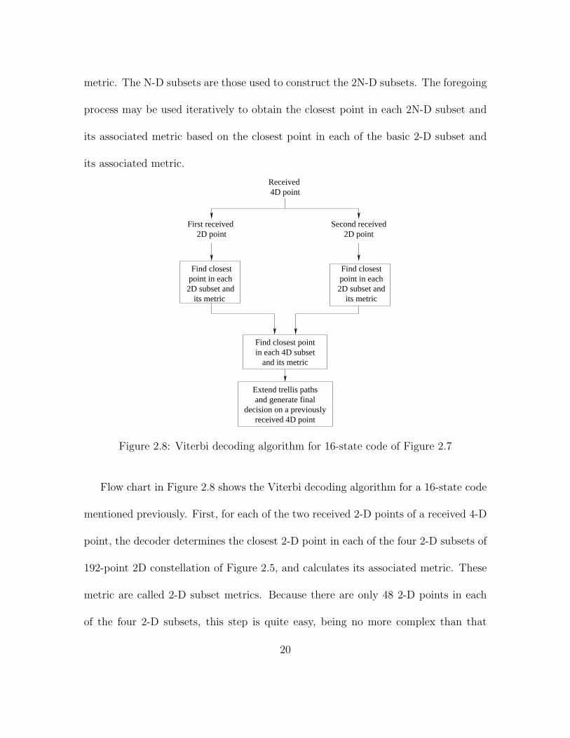
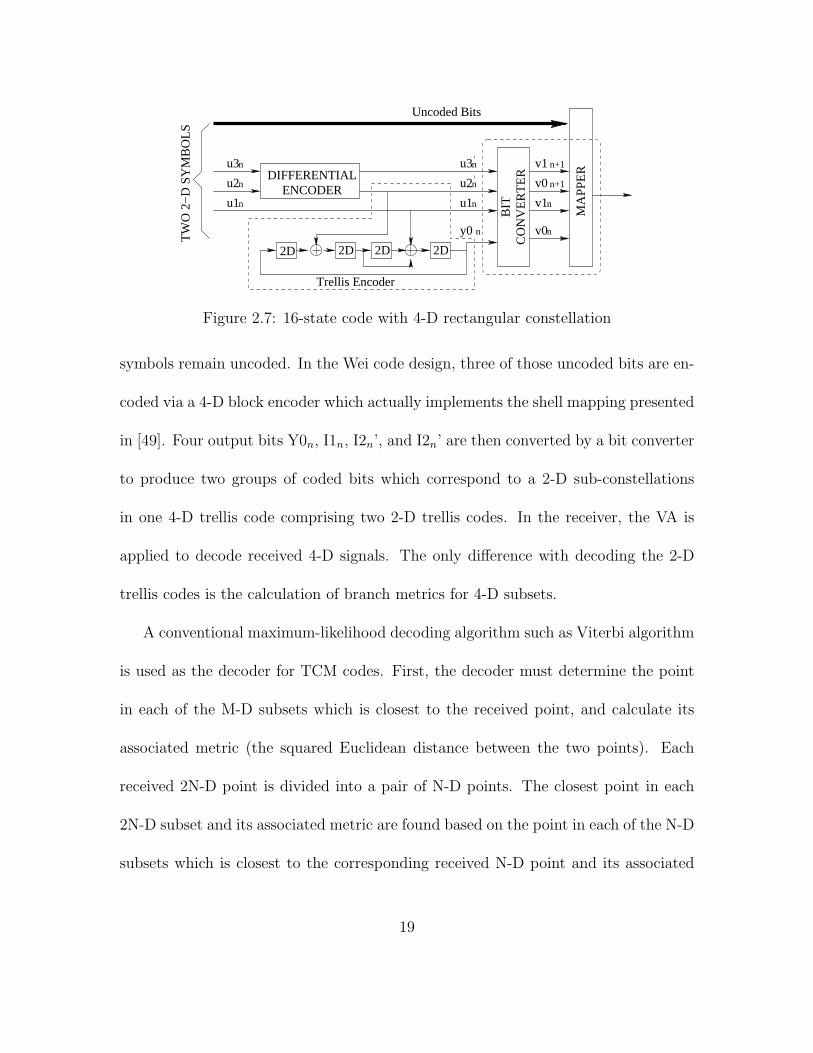
metric. The N-D subsets are those used to construct the 2N-D subsets. The foregoing
process may be used iteratively to obtain the closest point in each 2N-D subset and
its associated metric based on the closest point in each of the basic 2-D subset and
its associated metric.
received 4D point
point in each2D subset and
its metric
point in each 2D subset and
its metric
Find closest
Received 4D point
First received 2D point 2D point
Second received
Find closest pointin each 4D subset
and its metric
Extend trellis pathsand generate final
decision on a previously
Find closest
Figure 2.8: Viterbi decoding algorithm for 16-state code of Figure 2.7
Flow chart in Figure 2.8 shows the Viterbi decoding algorithm for a 16-state code
mentioned previously. First, for each of the two received 2-D points of a received 4-D
point, the decoder determines the closest 2-D point in each of the four 2-D subsets of
192-point 2D constellation of Figure 2.5, and calculates its associated metric. These
metric are called 2-D subset metrics. Because there are only 48 2-D points in each
of the four 2-D subsets, this step is quite easy, being no more complex than that
20

required for a 2-D code. Next, the decoder determines the closest 4-D point in each
of the 16 4-D types (see Table 2.1) and calculates its associated metric. These met-
rics are called 4-D type metrics. The 4-D type metric for a 4-D type is obtained by
adding the two 2-D subset metrics for the pair of 2-D subsets corresponding to that
4-D type. Finally, the decoder compares the two 4-D type metrics corresponding to
two 4-D types within each 4-D subset. The smaller 4-D type metric becomes the 4-D
subset metric associated with that 4-D subset, and the 4-D point associated with the
smallest 4-D type metric is the closest 4-D type point in that 4-D subset. These 4-D
subset metrics are then used to extend the trellis paths and generate final decisions
on the transmitted 4-D points in the usual way.
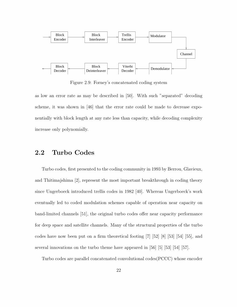
2.1.3 Forney’s Concatenated TCM
As a popular choice in digital communications, the Forney’s concatenated code
consists of two separate codes which are combined to form a large code [46]. Gener-
ally, Forney’s concatenated coding system includes a moderate-strength trellis inner
encoder, a powerful algebraic block outer encoder and a conventional block table-like
interleaver, as illustrated in Figure 2.9
In the decoder, firstly a maximum-likelihood (ML) or near-ML decoding algorithm
is used to achieve a moderate error rate like 10−2 − 10−3 at a code rate as close to
capacity as possible, then a block decoder is applied to drive the error rate down to
21
Channel
ViterbiDecoder
BlockDeinterleaver
BlockDecoder
Demodulator
BlockEncoder
BlockInterleaver
TrellisEncoder
Modulator
Figure 2.9: Forney’s concatenated coding system
as low an error rate as may be described in [50]. With such ”separated” decoding
scheme, it was shown in [46] that the error rate could be made to decrease expo-
nentially with block length at any rate less than capacity, while decoding complexity
increase only polynomially.
2.2 Turbo Codes
Turbo codes, first presented to the coding community in 1993 by Berrou, Glavieux,
and Thitimajshima [2], represent the most important breakthrough in coding theory
since Ungerboeck introduced trellis codes in 1982 [40]. Whereas Ungerboeck’s work
eventually led to coded modulation schemes capable of operation near capacity on
band-limited channels [51], the original turbo codes offer near capacity performance
for deep space and satellite channels. Many of the structural properties of the turbo
codes have now been put on a firm theoretical footing [7] [52] [8] [53] [54] [55], and
several innovations on the turbo theme have appeared in [56] [5] [53] [54] [57].
Turbo codes are parallel concatenated convolutional codes(PCCC) whose encoder
22

����
����
����
Delayline (L1)
RSC code(37, 21)
k
k
k
RSC code(37, 21)
C1
C2
u
D D D D
DDDD
x
yInterleaving
Figure 2.10: Basic turbo encoder (rate 1/3)
is formed by two or more constituent systematic encoder joined through one or more
interleavers. A turbo encoder is shown in Figure 2.10, which is formed by parallel
concatenation of two recursive systematic convolutional (RSC) encoder separated by
a pseudo-random interleaver. The data flow (uk at time k) goes directly to a first
elementary RSC encoder C1 and after interleaving, it feeds (un at time k) a second
elementary RSC encoder C2. These two encoders are not necessarily identical. Data
uk is systematically transmitted as symbol xk and redundancy y1k and y2k produced by
C1 and C2 may be completely transmitted for an R = 1/3 encoding or punctured for
higher rate. If the coded outputs (y1k, y2k) of encoder C1 and C2 are used respectively
n1 and n2 times and so on, the encoder C1 rate R1 and encoder C2 rate R2 are equal
to
R1 =n1 + n2
2n1 + n2
R2 =n1 + n2
n1 + 2n2
(II.1)
The suboptimal iterative decoding structure is modular, and consists of a set of
concatenated decoding modules, one for each constituent code, connected through
23

the same interleavers used at the encoder side. Such suboptimum iterative decod-
ing algorithm offers near-ML performance. Each component decoders are based on
a maximum a posteriori(MAP) probability algorithm or a soft output Viterbi al-
gorithm(SOVA) [58] generating a weighted soft estimate of the input sequence. The
iterative process performs the information exchange between the component decoders.
k
yy y
16 STATEDECODER
DEC1
16 STATEDECODER
DEC2
Inter−leaving
x
Latency: L1 Latency: L2
k
1k 2k
1k
n−L2
)n
DEMUX/INSERTION
(u
u1
u )(
Figure 2.11: Principle of the decoder in accordance with a serial concatenated scheme
The suboptimal iterative decoding structure is modular and consists of a set of
concatenated decoding modules, one for each constituent code, connected through the
same interleavers used at the encoder side. Each decoder performs weighted soft de-
coding of the input sequence. Bit error probabilities as low as 10−6 at Eb/N0 = −0.6
dB have been shown by simulation [59] using rates as low as 1/15. Parallel concate-
nated convolutional codes yield very large coding gains (10-11 dB) at the expense of
a date rate reduction or bandwidth increase.
The basic turbo decoder scheme can be depicted as in Figure 2.11 [2] [60]. Two
24

elementary decoders (DEC1 and DEC2) are concatenated in a serial format. The first
elementary decoder DEC1 is associated with lower rate R1 encoder C1 and yields a
soft (weighted) decision. The error burst at the decoder DEC1 output are scattered
by the interleaver and the encoder delay L1 is inserted to take the decoder DEC1 de-
lay into account. The redundant information yk is demultiplexed and sent to decoder
DEC1 when yk = y1k and toward decoder DEC2 when yk = y2k. When the redundant
information of a given encoder (C1 or C2) is not emitted, the corresponding decoder
input is set to zero.
The first decoder DEC1 deliver a weighted (soft) decision, Logarithm of Likeli-
hood Ratio (LLR) Λ1(uk) which is associated with each decoded bit uk, to the second
decoder DEC2.
Λ1(uk) = logPr{uk = 1/observation}Pr{uk = 0/observation}
(II.2)
where Pr{uk = 1/observation}, i = 0, 1 is the a posteriori probability (APP) of the
data bit uk.
As an optimum decoding algorithm, Viterbi algorithm doesn’t work here (espe-
cially for the first decoder DEC1) since it can not yield bit APP. Thus the BCJR [61]
algorithm was modified to decode RSC codes [2] [60]. Then the LLR Λ1(uk) associated
with each decoded bit uk becomes
Λ1(uk) = log
∑m λ1
k(m)∑m λ0
k(m)(II.3)
25

where λik is the joint probability defined by
λik = Pr{uk = i, Sk = m|RN
1 } (II.4)
Sk is the encoder state with K-tuple, RN1 is the received codeword sequence. Finally
the decoder can make decision by comparing Λ1(uk) to a threshold equal to zero
uk = 1 if Λ1(uk) > 0
uk = 0 if Λ1(uk) < 0
(II.5)Following
the BCJR algorithm [61], equation (II.3) can be further expanded as
Λ1(uk) = log
∑m
∑m′
∑1j=0 γ1(Rk, m
′, m)αjk−1(m
′)β k(m)∑m
∑m′
∑1j=0 γ0(Rk, m′, m)αj
k−1(m′)β k(m)
(II.6)
In [2] [60], if the decoder inputs are independent, the LLR Λ1(uk) can be decom-
posed into two parts:
Λ1(uk) = logp(xk|uk = 1)
p(xk|uk = 0)+ log
∑m
∑m′
∑1j=0 γ1(yk, m
′, m)αjk−1(m
′)β k(m)∑m
∑m′
∑1j=0 γ0(yk, m′, m)αj
k−1(m′)β k(m)
(II.7)
Conditionally to uk = 1 (resp. uk = 0), variable xk are Gaussian with mean 1 (resp.
-1) and variance σ2, thus the LLR Λ(uk) is still equal to
Λ1(uk) =2
σ2xk + Wk (II.8)
where
Wk = Λ1(uk)|xk=0 = log
∑m
∑m′
∑1j=0 γ1(yk, m
′, m)αjk−1(m
′)β k(m)∑m
∑m′
∑1j=0 γ0(yk, m′, m)αj
k−1(m′)β k(m)
(II.9)
26

Wk is a function of the redundant information introduced by the encoder and does
not depend on the decoder input. It represents the extrinsic information supplied by
the decoder.
u
yy
y
16 STATEDECODER
DEC1
Inter−leaving
k
1k
1 deinter−leaving
deinter−leaving
kx
k
w 2kkz
INSERTIONDEMUX/
k)16 STATEDECODER
DEC2
2k
)n
decodedoutput
(1
u (u
Figure 2.12: Feedback decoder for turbo codes
Thus a feedback decoder scheme can be used for decoding the two parallel con-
catenated encoders [2]. Figure 2.12 illustrates the realization of the above idea. Now
both decoders can use modified BCJR algorithm, since for the second decoder, we
have
Λ2(uk) = f(Λ1(uk)) + W2k (II.10)
with
Λ1(uk) =2
σ2xk + W1k (II.11)
Due to the presence of interleaving between DEC1 and DEC2, extrinsic information
and observation xk, y1k are weakly correlated. Therefore, W2k and xk, y1k can be
jointly used for carrying out a new decoding of bit uk with LLRs being rewritten as:
27

Λ1(uk) =2
σ2xk +
2
σ2z
zk + W1k
Λ1(un) = Λ1(un)zn=0
zk = W2k = Λ2(uk)|Λ1(uk)=0
(II.12)and
decision at the decoder would be
uk = [Λ2(uk)] (II.13)
By increasing the number of iterations in the turbo decoding, the bit error proba-
bility as low as 10−5− 10−7 can be achieved at a SNR close to the fundamental limits
established by Shannon.
2.3 Turbo Trellis Coded Modulation
The merge of TCM and PCCC was proposed to achieve simultaneously large
encoding gains and high bandwidth efficiency [7] [13] [12] [17] [9]. For Gaussian
channels, turbo-coded modulation techniques can be broadly classified into binary
schemes and turbo trellis-coded modulation. The first group can be further divided
into ”pragmatic” scheme with a single component binary turbo code and multilevel
binary turbo codes. Turbo trellis-coded modulation schemes can be classified into
two cases puncturing either parity symbol or information symbol.
28

2.3.1 Binary Turbo Coded Modulation
In pragmatic turbo coded modulation design [12], a single binary turbo code of
rate 1/n is used as the component code. The output of the turbo encoder is then
simply mapped onto an M -ary modulator. Decoding is done by calculating the log-
likelihood function for each encoded binary digit based on the received noisy symbol
and the signal subsets in the signal constellation specified by each binary digit. The
stream of the bit likelihood values is then passed to the binary turbo decoder which
can be based either on MAP or soft output Viterbi algorithms (SOVA). By modifying
the puncturing function and modulation signal constellation, it is possible to obtain
a large family of turbo coded modulation schemes. However, although this system
utilizes a bandwidth efficient modulation scheme, the encoder and modulator are not
designed cooperatively as in TCM systems.
Multilevel turbo codes are constructed by using turbo codes as the component
codes in [17] [62]. The transmitter for an M -ary signal constellation consists of
l = logM2 parallel binary encoders as shown in Figure 2.13.
u Serial/Parallel
Converter
Turbo Encoder l
Turbo Encoder 2
Turbo Encoder 1
MapperSignal
1
2
l l
2
1
......
v
v
v
a
u
u
u
Figure 2.13: Multilevel turbo encoder
29

A message sequence is split into l blocks. Each message block ui is then encoded
by an individual binary turbo encoder. The output digits of the encoders form a
binary vector (v1,v2, ...,vl), which is mapped onto an M -ary signal constellation.
The maximum likelihood decoder operates on the overall code trellis. In general,
however, this decoder is too complicated to implement. Alternatively, a suboptimum
technique, called multistage decoding [63], can be used, resulting the same asymptotic
error performance as the maximum likelihood decoding.
The most significant contribution of Wachsmann and Huber is that they proposed
a technique for selecting the component code rates. In this design, the component rate
at a particular modulation level, is chosen to be equal to the equivalent binary input
channel associated with that level. For infinite code lengths, in theory, as the overall
channel capacity equals to the sum of the channel capacities for all levels, this design
results in error free decoding. Therefore, they are suitable candidates for component
codes in a multilevel scheme. And the good performance leads to the assumption of
the negligible error propagation between modulation levels, which enables the multi-
stage decoding. However, for small block size, there could be significant loss in terms
of the SNR needed to achieve a certain BER.
2.3.2 Symbol interleaved Turbo TCM
In [9] [10], a turbo trellis-coded modulation (TTCM) system was presented in
30

which two recursive Ungerboeck type trellis codes with rate k/(k+1) are concatenated
in parallel. Figure 2.14 shows the encoder structure comprising of two recursive
convolutional encoders linked by a symbol interleaver and followed by a signal mapper.
v
Interleaver
Encoder 1
Encoder 2
Mapper 1
SymbolDeinterleaver
Mapper 2k bits k + 1 bits
k bits k + 1 bits
l
u
l~
uv
v
v
Symbol
Figure 2.14: Turbo TCM encoder with parity symbol puncturing
It is noted that the interleaver is constrained to interleave symbols. That is,
the ordering of k information bits arriving at the interleaver at a particular instant
remains unchanged. For the component trellis code, some of the input bits may not
be encoded. In practical implementations these inputs do not need to be interleaved,
but are directly used to select the final point in a signal subset. At the receiver, the
values of these bits are estimated by set decoding [40].
The output of the second encoder is de-interleaved. This ensures that the k
information bits which determine the encoded (k +1) binary digits of both the upper
and lower encoder at a given time instant are identical. The selector then alternately
connects the upper and lower encoder to the channel. Thus, the parity symbols is
alternately chosen from the upper and lower encoder. Each information group appears
31

in the transmitted sequence only once.
In the receiver, the log-MAP algorithm or SOVA decoding algorithms are used to
decode the turbo codes except that the symbol probability is used as the extrinsic
information rather than the bit probability.
2.3.3 Bit interleaved Turbo TCM
As a different type of turbo TCM scheme, parallel concatenation of two recursive
trellis codes with puncturing of systematic bits was proposed by Benedetto, Divsalar,
Montorsi and Pollara [13]. The basic idea of the scheme is to puncture the output
symbols of each trellis encoder and select the puncturing pattern such that the output
symbols of the parallel concatenated code contains the input information only once.
The simple method to realize above idea is first to select a rate bb+1
constituent code
where the outputs are mapped to a 2b+1-level modulation based on Ungerboeck’s set
partitioning [41]. If MPSK modulation is used, for every b bits at the input of the
parallel concatenated encoder we transmit two consecutive 2b+1 PSK signals, one per
each encoder output. For the case of using M-QAM modulation, the b + 1 outputs
of the first component encoder are mapped into the 2b+1 in-phase level (I-channel)
of 22b+2-QAM signal set, and the b + 1 outputs of the second component encoder are
mapped into the 2b+1 quadrature level (Q-channel). The throughput of these two
system are b/2 bits/sec/Hz and b bits/sec/Hz. respectively.
32

A better solution to parallel concatenated TCM (PCTCM) is to select b/2 system-
atic outputs from the first constituent encoder and puncture the rest of the systematic
outputs, but use the parity bit of the bb+1
code. Then do the same to the second con-
stituent code, but select only those systematic bits which were punctured in the
first encoder. Two interleavers will be required in this system, the first interleaver
permutes the bits selected by the first encoder and the second one interleave those
punctured by the first encoder. 21+b/2 PSK symbols per encoder can be used for
MPSK to achieve throughput of b/2. And 21+b/2 levels can be used for both I-channel
and Q-channel in M-QAM to achieve the throughput of b bits/sec/Hz. A 16QAM
turbo trellis-coded modulation encoder is given in Figure 2.15.
D
����
����
��������
����
����
����
����
����
����
����
����
����
A
A
A
A
B
B
B
B
QAM162 1
1
2u
u
D D D D
D D D
Figure 2.15: Trubo trellis-coded modulation, 16 QAM, 2bits/s/Hz
Decoding this type of turbo TCM is a straightforward application of the iterative
symbol-by-symbol MAP algorithm for a binary turbo codes. The only differences
33
are: 1) the extrinsic information computed for a symbol needs to be converted to a
bit level since they are carried out on a bit level; 2) after interleaving/de-interleaving
operations, the bit a priori probabilities need to be converted to a symbol level since
they will be used in the branch transition probability calculation in the symbol MAP
algorithm [64].
2.4 Multicarrier Modulation and OFDM
An alternative approach to the design of bandwidth-efficient communication sys-
tem in the presence of channel distortion is to subdivide the available channel band-
width into a number of equal-bandwidth subchannels, where the bandwidth of each
subchannel is sufficiently narrow so that the frequency response characteristics of
the subchannels are nearly ideal. Such a subdivision of the overall bandwidth into
smaller subchannels is referred to as multicarrier modulation (MCM). The basic idea
of multicarrier modulation is quite simple and follows naturally from the competing
desires for high data rates and intersymbol interference (ISI) free channels. In order
to have a channel that does not have ISI, the symbol time Tsym has to be larger -
often significantly larger - than the channel delay spread Tm. Typically, it is assumed
that Tsym ≈ 10Tm in order to satisfy this ISI-free condition [65].
Multicarrier modulation divides the high-rate transmit bitstreams into N parallel
low-rate substreams, each of which has Tsym � Tm, and is hence ISI-free. These
34

individual substreams can then be sent over N parallel subchannels, maitaining the
total desired data rate. Consequently, the data is transmitted by frequency-division
multiplexing (FDM). By selecting the symbol rate 1/Tsym on each of the subchannels
to be equal to the separation ∆f of adjacent subcarriers, the subcarriers are orthogo-
nal over the symbol interval Tsym and independent of the relative phase relationship
between subcarriers. In this case, we have orthogonal frequency-division multiplexing
(OFDM). The data rate on each subchannel is much less than the total data rate,
and so the corresponding subchannel bandwidth is much less than the total system
bandwidth. The number of substreams is chosen to insure that each subchannel has
a bandwidth less than the coherence bandwidth of the channel, so the subchannels
experience relatively flat fading. Thus, the ISI on each subchannel is small. Moreover,
in the discrete implementation of OFDM, often called discrete multitone (DMT), the
ISI can be completely eliminated through the use of a cyclic prefix. The subchannels
in OFDM need not be contiguous, so a large continuous block of spectrum is not
needed for high rate multicarrier communications.
Over the past few years, there has been increasing interest in multicarrier mod-
ulation for a variety of applications. However, multicarrier modulation is not a new
technique. It was first used for military HF radios in the late 1950’s and early
1960’s. Starting around 1990, multicarrier modulation has been used in many di-
verse wired and wireless applications, such as Digital Audio Broadcasting in Europe,
digital subscribe lines (DSL) and newly emerging uses for multicarrier techniques in-
35

cluding fixed wireless broadband services and mobile wireless broadband known as
FLASH-OFDM [65]. One of OFDM’s successes is its adoption as the standard of
choice in Wireless Personal Area Networks (WPAN) and Wireless Local Area Net-
work (WLAN) systems (e.g., IEEE P802.15-03 [39], IEEE 802.11a, IEEE 802.11g,
Hiper-LAN II).
2.4.1 Data Transmission Using Multicarriers
The simplest form of multicarrier modulation divides the data stream into mul-
tiple substreams to be transmitted over different orthogonal subchannels centered at
different subcarrier frequencies. Consider a linearly-modulated system with data rate
R and passband bandwidth B. The coherence bandwidth for the channel is assume to
be Bc < B, so the signal experiences frequency-selective fading. The basic premise of
multicarrier modulation is to break this wideband system into N linearly-modulated
subsystems in parallel, each with subchannel bandwidth BN = B/N and data rate
RN = R/N . For N sufficiently large, the subchannel bandwidth BN � Bc, which in-
sures relatively flat fading on each subchannel. This can also be seen in time domain:
the symbol time TN of the modulated signal in each subchannel is proportional to the
subchannel bandwidth 1/BN . So BN � Bc implies that TN ≈ 1/BN � 1/Bc ≈ Tm,
where Tm denotes the delay spread of the channel. Thus, if NST is sufficiently large,
the symbol time is much bigger than the delay spread, so each subchannel experience
36

little ISI degradation.
Figure 2.16 illustrates a multicarrier transmitter. The bit stream is divided into N
substreams via a serial-to-parallel converter. The nth substream is linearly-modulated
(typically via QAM or PSK) relative to the subcarrier frequency fn and occupies pass-
band BN . We assume coherent demodulation of the subcariers so the subcarrier phase
is neglected in our analysis. If we assume raised cosine pulses for g(t) we get a sym-
bol time TN = (1 + β)/BN for each substream, where β is the rolloff factor of the
pulse shape. The modulated signals associated with all the subchannels are summed
together to form the transmitted signal, given as
s(t) =N−1∑i=0
sig(t)cos(2πfit + φi), (II.14)
where si is the complex symbol associated with the ith subcarrier and φi is the phase
offset of the ith carrier. For nonoverlapping subchannels we set fi = f0 + i(BN), i =
0, . . . , N − 1. The substreams then occupy orthogonal subchannels with passband
bandwidth BN , yielding a total passband bandwidth NBN = B and data rate
NRN ≈ R. Thus, this form of multicarrier modulation does not change the data
rate or signal bandwidth relative to the original system, but it almost completely
eliminates ISI for BN � Bc.
The receiver for this multicarrier modulation is shown in Figure 2.18. Each sub-
stream is passed through a narrowband filter to remove the other substreams, de-
modulated, and combined via a parallel-to-serial converter to form the original data
37

Figure 2.16: Multicarrier transmitter.
Figure 2.17: Transmitted signal.
38

stream. Note that the ith subchannel will be affected by flat fading corresponding to
a channel gain αi =| H(fi) |.
Although this simple type of multicarrier modulation is easy to understand, it has
several significant shortcomings. First, in a realistic implementation, subchannels
will occupy a large bandwidth than under ideal raised pulse shaping since the pulse
shape must be time-limited. Let ε/TN denote the additional bandwidth required sue
to time-limiting of these pulse shapes. The subchannels must then be separated by
(1 + β + ε)/TN , and since the multicarrier system has N subchannels, the bandwidth
penalty for time limiting is εN/TN . In particular, the total required bandwidth for
nonoverlapping subchannels is
B =N(1 + β + ε)
TN
(II.15)
Thus, this form of multicarrier modulation can be spectrally ineffecient. Additionally,
near-ideal (and hence expensive) low pass filters will be required to maintain the or-
thogonality of the subcarriers at the receiver. Perhaps most importantly, this scheme
requires N independent modulators and demodulators, which entails significant ex-
pense, size, and power consumption. Section 2.4.3 presents the discrete implementa-
tion of multicarrier modulation, which eliminates the need for multiple modulators
and demodulators.
39
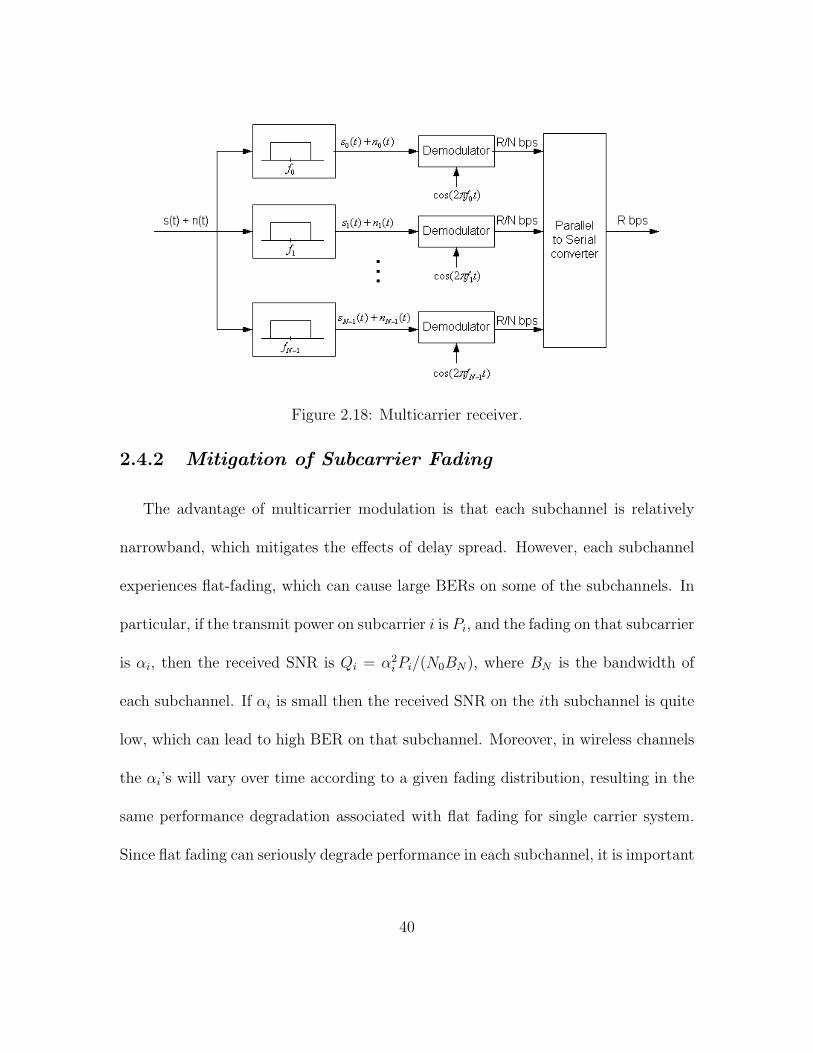
Figure 2.18: Multicarrier receiver.
2.4.2 Mitigation of Subcarrier Fading
The advantage of multicarrier modulation is that each subchannel is relatively
narrowband, which mitigates the effects of delay spread. However, each subchannel
experiences flat-fading, which can cause large BERs on some of the subchannels. In
particular, if the transmit power on subcarrier i is Pi, and the fading on that subcarrier
is αi, then the received SNR is Qi = α2i Pi/(N0BN), where BN is the bandwidth of
each subchannel. If αi is small then the received SNR on the ith subchannel is quite
low, which can lead to high BER on that subchannel. Moreover, in wireless channels
the αi’s will vary over time according to a given fading distribution, resulting in the
same performance degradation associated with flat fading for single carrier system.
Since flat fading can seriously degrade performance in each subchannel, it is important
40

to compensate for flat fading in the subchannels. There are several techniques for
doing this, including coding with interleaving over time and frequency, frequency
equalization, precoding, and adaptive loading and etc. Moreover, in rapidly changing
channels it is difficult to estimate the channel at the receiver and feed this information
back to the trnasmitter. Without channel information at the transmitter, precoding
and adaptive loading cannot be done, so only coding with interleaving is effective at
fading mitigation, which will be discussed shortly [65].
Coding with Interleaving over Time and Frequency
The basic idea in coding with interleaving over time and frequency is to encode
data into codewords, interleave the resulting coded bits over both time and frequency,
and then transmit the coded bits over different subchannels such that the coded bits
within a given codeword all experience independent fading. If most of the subchan-
nels have a high SNR, the codeword will have most coded bits received correctly, and
the errors associated with the few bad subchanneld can be corrected. Coding across
subchannels basically exploits the frequency diversity inherent to a multicarrier sys-
tem to correct errors. This technique only works well if there is sufficient frequency
diversity across the total system bandwidth, which will significantly reduce the ef-
fect of coding. Most coding for OFDM assumes channel information in the decoder.
Channel estimates are typically obtained by a two dimensional pilot symbol trans-
mission ove rboth time and frequency.
41
Note that coding with frequency/time interleaving takes advantage of the fact
that data on all the subcarriers is associated with the same user, and can therefore
be jointly processed. The other techniques for fading mitigation discussed in sub-
sections are all basically flat fading compensation techniques, which apply equally to
multicarrier systems as well as narrowband flat fading single carrier systems.
Frequency Equalization
In frequency equalization the flat fading αi on the ith subchannel is basically
inverted in the receiver. Specifically, the received signal is multiplied by 1/αi, which
gives a resultant signal power α2i Pi/α
2i = Pi. While this removes the impact of flat
fading on the signal, it enhances the noise. Specifically, the incoming noise signal is
also multiplied by 1/αi, so the noise power becomes N0BN/α2i and the resultant SNR
on the ith subchannel after frequency equalization is the same as before equalization.
Therefore, frequency equalization does not really change the performance degradation
association with subcarrier flat fading. Other techniques regarding flat fading can also
be found in [65].
2.4.3 Discrete Implementation of Multicarrier
Although multicarrier modulation was invented in the 1950’s, its requirement for
separate modulators and demodulators on each subchannel was far too complex for
the most system implementations at the time. However, the development of simple
42

and cheap implementation of the discrete Fourier transform (DFT) and the inverse
DFT (IDFT) twenty years later, combined with the realization that multicarrier mod-
ulation can be implemented with these algorithms, ignited its widespread use. In this
section, we will illustrate OFDM, which implements multicarrier modulation using
DFT and IDFT.
The DFT and Its Properties
Let x[n], 0 ≤ n ≤ N − 1, denote a discrete time sequence. The N -point DFT of
x[n] is defined as
DFT{x[n]} = X[i] ,1√N
N−1∑n=0
x[n]e−j 2πniN , 0 ≤ i ≤ N − 1. (II.16)
where X[i] characterizes the frequency content of the time samples x[n] associated
with the original signal x(t). The sequence x[n] can be recovered from its DFT using
IDFT:
IDFT{X[i]} = x[n] ,1√N
N−1∑n=0
x[n]ej 2πniN , 0 ≤ i ≤ N − 1. (II.17)
The DFT and its inverse are typically performed in hardware using fast Frourier
transform (FFT) and inverse FFT (IFFT).
When an input data stream x[n] is sent through a linear time-invariant discrete-
time channel h[n], the output y[n] is the discrete-time convolution of the input and
the channel impulse response:
y[n] = h[n] ∗ x[n] = x[n] ∗ h[n] =∑
k
h[k]x[n− k]. (II.18)
43
The N -point circular convolution of x[n] and h[n] is defined as
y[n] = h[n]⊗ x[n] = x[n]⊗ h[n] =∑
k
h[k]x[n− k]N . (II.19)
where [n − k]N denotes [n − k] modulo N . In other words, x[n − k]N is a periodic
version of x[n− k] with period N . It is easily verified that y[n] given by II.20 is also
periodic with period N . From the definition of the DFT, circular convolution in time
leads to multiplication in frequency:
DFT{y[n] = h[n]⊗ x[n]} = X[i]H[i], 0 ≤ i ≤ N − 1. (II.20)
If the channel and input are circularly convoluted then if h[n] is known at the receiver,
the original data sequence x[n] can be recovered by taking the IDFT of Y [i]/H[i], 0 ≤
i ≤ N − 1. Unfortunately, the channel outpyt is not a circular convolution but a
linear convolution. However, the linear convolution between the channel input and
impulse response can be turned into a circular convolution by adding a specific prefix
to the input called a cyclic prefix.
The Cyclic Prefix
Consider a channel input sequence x[n] = x[0], . . . , x[N − 1] of length N and
a discrete-time channel with finite impulse response (FIR) h[n] = h[0], . . . , h[µ] of
length µ + 1 = Tm/Ts, where Tm is the channel delay spread and Ts the sampling
time associated with the discrete time sequence. The cyclic prefix for x[n] is defined as
{x[N−µ], . . . , x[N−1]}: it consists of the last L values of the x[n] sequence. For each
44

input sequence of length N , these last µ samples are appended to the beginning of the
sequence. This yields a new sequence x[n],−µ ≤ n ≤ N − 1, of length N + µ, where
x[−µ], . . . , x[N − 1], x[0], . . . , x[N − 1], as shown in Figure2.19. Note that with this
definition, x[n] = x[n]N for −µ ≤ n ≤ N − 1, which implies that x[n− k] = x[n− k]N
for −µ ≤ n− k ≤ N − 1.
Figure 2.19: Cyclic prefix of length µ.
Suppose x is input to a discrete-time channel with impulse response h[n]. The
channel output y[n], 0 ≤ n ≤ N − 1 is then
H = x[n] ∗ h[n]
=
µ−1∑k=0
h[k]x[n− k]
=
µ−1∑k=0
h[k]x[n− k]N
= x[n]⊗ h[n],
where the third equality follows from the fact that for 0 ≤ k ≤ µ − 1, x[n − k] =
x[n − k]N for 0 ≤ n ≤ N − 1. Thus, by appending a cyclic prefix to the channel
input, the linear convolution associated with the channel impulse response y[n] for
45

0 ≤ n ≤ N − 1, becomes a circular convolution. Taking the DFT of the channel
output in the absence of noise then yields
Y [i] = DFT{y[n] = x[n]⊗ h[n]} = X[i]H[i], 0 ≤ i ≤ N − 1. (II.21)
and the input sequence x[n], 0 ≤ n ≤ N−1, can be recovered from the channel output
y[n] for 0 ≤ n ≤ N − 1, for known h[n] by
x[n] = IDFT{Y [i]/H[i]} = IDFT{DFT{y[n]}/DFT{h[n]}}. (II.22)
Note that y[n],−µ ≤ n ≤ N − 1, has length N + µ, yet from (II.22) the first
µ samples y[−µ], . . . , y[−1] are not needed to recover x[n], 0 ≤ n ≤ N − 1, due to
the redundancy associated with the cyclic prefix. Moreover, if we assume that the
input x[n] is divided into data blocks of size N with a cyclic prefix appended to each
block to form x[n], then the first µ samples of y[n] = h[n] ∗ x[n] in a given block are
corrupted by InterBlock Interference (IBI) associated with the last µ samples of x[n]
in the priori block, as illustrated in Figure2.20. The cyclic prefix serves to eliminate
IBI between the data blocks since the first µ samples of the channel output affected
by this IBI can be discarded without any loss relative to the original information
sequence. In continuous time this is equivalent to using a guard band of duration
Tm (the channel delay spread) after every block of N symbols of duration NTsym to
eliminate the IBI between these data blocks.
The benefits of adding a cyclic prefix come at a cost. Since µ symbols are added to
the input data blocks, there is an overhead of µ/N , resulting in a data rate reduction
46

Figure 2.20: ISI between data blocks in channel output.
of N/(µ + N). The transmit power associated with sending the cyclic prefix is also
wasted since this prefix consists of redundant data. It is clear from Figure 2.20 that
any prefix of length µ appended to input blocks of size N eliminates IBI between
data blocks if the first µ samples of the block are discarded. In particular, the prefix
can consist of all zero symbols, in which case although the data rate is still reduced,
no power is used in transmitting the prefix. The tradeoffs associated with the cyclic
prefix versus this all-zero prefix will be discussed in Chap III.
The above analysis motivates the design of OFDM. In OFDM, the input data is
divided into blocks of size Z refered to as an OFDM symbol. A cyclic prefix is added
to each OFDM symbol to induce circular convolution of the input and channel impulse
response. At the receiver, the output samples affected by IBI between OFDM symbols
are removed. The DFT of the remaining samples are used to recover the original input
sequence. Details of the OFDM system design will be given in next section.
Orthogonal Frequency Division Multiplexing (OFDM)
The OFDM implementation of multicarrier modulation is shown in Figure 2.21.
The input data stream is modulated by a QAM modulator, resulting a complex sym-
47

bol X[0], X[1], . . . , X[N−1]. This symbol stream is passed through a serial-to-parallel
converter, whose output is a set of N parallel QAM symbols X[0], X[1], . . . , X[N −1]
corresponding to the symbols transmitted over each of hte subcarriers. Thus, the N
symbols output from the serial-to-parallel converter are the discrete frequency compo-
nents of the OFDM modulator output s(t). In order to generate s(t), these frequency
components are converted into time samples by performing an inverse DFT on these
N symbols, which is efficiently implemented using the IFFT algorithm. The IFFT
yields the OFDM symbol consisting of the sequence x[n] = x[0], . . . , x[N−1] of length
N , where
x[n] =1√N
N−1∑i=0
X[i]ej2πni/N , 0 ≤ n ≤ N − 1. (II.23)
This sequence corresponds to samples of the multicarrier signal: i.e. the multicarrier
signal consists of linearly modulated subchannels, and right hand side of (II.23) corre-
sponds to samples of a sum of QAM symbols X[i] each modulated by carrier frequency
ei2πni/TN , i = 0, . . . , N − 1. The cyclic prefix is then added to the OFDM symbol, and
the resulting time samples x[n] = x[−µ], . . . , x[N−1] = x[N−µ], . . . , x[0], . . . , x[N−1]
are ordered by the parallel-to-serial converter and pass through a D/A converter, re-
sulting in baseband OFDM signal x(t), which is then upconverted to frequency f0.
The transmitted signal is fitted by the channel impulse response h(t) and cor-
rupted by additive noise, so that the received signal is y(t) = x(t) ∗ h(t) + n(t).
This signal is downconverted to baseband and filtered to remove the high frequency
48

components. The A/D converter samples the resulting signal to obtain y[n] =
x(n) ∗ h(n) + v(n),−µ ≤ n ≤ N − 1. The prefix of y[n] consisting og the first µ
samples is then removed. This results in N times samp;es whose DFT in the ab-
sence of noise is Y [i] = H[i]X[i]. These time samples are serial-to-parallel converted
and passed through an FFT, which results in scaled versions of the original symbols
H[i]X[i], where H[i] = H[fi] is the flat-fading channel gain associated with the ith
subchannel. the FFT output is parallel-ti-serial converted and passed through a QAM
demodulator to recover the original data.
The OFDM system effectively decompose the wideband channel into a set of
narrowband orthogonal subchannels with a different QAM symbol sent over each
subchannel. Knowledge of the channel gains H[i], i = 0, . . . , N − 1 is not needed for
this decomposition, in he same way that a continuous time channel with frequency
response H[f ] can be divided into orthogonal subchannels without knowledge of H[f ]
by splitting the total signal bandwidth into nonoverlapping subbands. The demodu-
lator can use the channel gains to recover the original QAM symbols by dividing out
these gains: X[i] = Y [i]/H[i]. This process is called frequency equalization. How-
ever, frequency equalization leads to noise enhancement, since the noise in the ith
subchannel is also scaled by 1/H[i].
49

Figure 2.21: OFDM with IFFT/FFT implementation.
50

CHAPTER III
TURBO TCM CODED OFDM
SYSTEM FOR UWB CHANNELS
Ultra-wideband (UWB) radio is a fast emerging technology with uniquely attrac-
tive features inviting major advances in wireless communications, networking, radar,
imaging, and positioning system. By its rule-making proposal in 2002, the FCC es-
sentially unleashed new bandwidth of (3.6-10.1 GHz) at the noise floor, where UWB
radios overlapping coexistent RF systems can operate using low-power ultra-short
information bearing pulses. This leads to a rapidly growing research efforts targeting
a host of UWB applications, such as short-range high-speed access to internet, covert
communication links, localization at centimeter-meter level accuracy, high-resolution
ground-penetration radar, through-wall imaging, precision navigation and asset track-
ing, just to name a few. UWB characterizes transmission system with instantaneous
51

spectral occupancy in excess of 500 MHz. Such systems rely on ultra-short waveforms
that can be free of sine-wave carriers and do not require IF processing because they
can operate at baseband.
It is essential for a wireless system to deal with the existence of multiple prop-
agation paths (multipath) exhibiting different delays, resulting from objects in the
environment causing multiple reflections on the way to the receiver. The large band-
width of UWB waveforms significantly increases the ability of the receiver to resolve
the different reflections in the channel. Two basic solutions for inter-symbol interfer-
ence (ISI) caused by multi-path channels are equalization and orthogonal frequency-
division multiplexing (OFDM) [31].
OFDM has been a promising solution for efficiently capturing multipath energy
in highly dispersive UWB channels and delivering high data rate transmission. One
of OFDM’s successes is its adoption as the standard of choice in Wireless Personal
Area Networks (WPAN) and Wireless Local Area Network (WLAN) systems (e.g.,
IEEE P802.15-03 [39], IEEE 802.11a, IEEE 802.11g, Hiper-LAN II). Convolutional
encoded OFDM has been introduced in the proposed standard to combat flat fading
experienced in each subcarrier [66] [67]. The incoming information bits are channel
coded prior to serial-to-parallel conversion and carefully interleaved. This procedure
splits the information to be transmitted over a large number of subcarriers, and at the
same time, provides a link between bits transmitted on those separated subcarriers
of the signal spectrum in such a way that information conveyed by faded subcarriers
52
can be reconstructed through the coding link to the information conveyed by well-
received subcarriers.
One of UWB proposals in the IEEE P802.15 WPAN project is to use a multi-band
orthogonal frequency-division multiplexing (OFDM) system and punctured convolu-
tional codes for UWB channels supporting data rate up to 480Mb/s. In this section
we examine the possibility of improving the proposed system using Turbo TCM with
QAM constellation for higher data rate transmission. We construct a punctured
parity-concatenated trellis codes in which a TCM code is used as the inner code and
a simple parity-check code is used as the outer code. Then, the bit performance is
examined when applied to the OFDM systems in the UWB channel environments.
The study shows that the system can offer data rate of 640Mbps via 16QAM modu-
lation and 1.2 Gbps via 64QAM modulation. The code performance is confirmed by
density evolution.
53

TT
CM
E
ncod
er
Seri
al
to
Para
llel
(S/P
)
OFD
M
Mod
ulat
ion
(IFF
T)
Zer
o Pa
ddin
g +
P/
S
. . .
TT
CM
D
ecod
er
Para
llel
to
Seri
al
(P/S
)
OFD
M
Dem
odul
atio
n (F
FT)
S/P +
Ove
rlap
A
dd
. . .
Tra
nsm
itter
Rec
eive
r
Sou
rce
Bits
Sou
rce
Bits
Rec
over
ed
CO
FD
M S
igna
l
CO
FD
M S
igna
l
Rec
eive
d
0
Figure 3.1: Block diagram of coded OFDM system.
54

3.1 OFDM System For UWB Channel
The block diagram of the functions included in the coded OFDM system is pre-
sented in figure 3.1. On the transmitter side, source information bits are first en-
coded and then mapped onto a higher sized constellation, such as QPSK, 16QAM or
64QAM. Then, the streams of mapped complex numbers are grouped to modulate
subcarriers in OFDM frequency band. FFT and inverse FFT (IFFT) are used for a
simple implementation [66]. IFFT is performed to construct so-called “time domain”
OFDM symbols, as we mentioned in chapter II. In order to enable a very simple
equalization scheme in the frequency domain, classic multicarrier systems insert at
the transmitter, after IFFT modulation, a time-domain redundant Cyclic Prefix (CP)
of length larger than the FIR channel memory. At the receiver side, the reverse or-
der operations are performed to recover the source information. CP is discarded to
avoid inter-block interference (IBI) and each truncated block is FFT processed - an
operation converting the frequency-selective channel output into parallel flat-faded
independent subchannel outputs each corresponding to a different subcarrier. Unless
zero, flat fads are removed by dividing each subchannel output with a simple gain
equal to the channel transfer function values at the corresponding subcarrier.
Instead of inserting the CP, it was proposed recently in [68] to pad Zeros (a null
signal) at the end of each IFFT modulated block. This new modulation, so termed
Zero-padding OFDM (ZP-OFDM), introduces the same amount of redundancy as CP-
55

OFDM and thus results in the same bit rate loss. Interestingly, ZP-OFDM assures
channel-irrespective retrieval of the transmitted symbol blocks even when a channel
zero is located on a subcarrier which is not possible possible with CP-OFDM. The
price paid by ZP-OFDM is increased receiver compexity (the single FFT requied by
CP-OFDM is replaced by FIR filtering). We will focus on CP-OFDM in this chapter
to describe the OFDM system. The details for ZP-OFDM and the equalization dif-
ference between CP-OFDM and ZP-OFDM will be explained in section 4.2.5.
The FCC specifies that a system must occupy a minimum of 500 MHz bandwidth
in order to be classified as an UWB system. The P802.15-03 project defined an unique
numbering system for all channels having a spacing of 528MHz and lying within the
band 3.1 - 10.6 GHz [39]. According to [69], a 128-point FFT with cyclic prefix length
of 60.6ns outperforms a 64-point FFT with a prefix length of 54.9ns by approximately
0.9dB. Therefore, we focus on an OFDM system with a 128-point FFT and 528MHz
operating bandwidth.
3.1.1 16QAM Turbo TCM Encoder Structure
In chapter II, three turbo TCM coding scheme were discussed. Simulation results
show that TTCM proposed by Benedetto [13] outperforms the other two schemes.
There are two bit interleavers and two constituent encoders involved in Benedetto’s
TTCM scheme. The first interleaver permutes the bits selected by the first constituent
56
encoder and second one interleaves those bits punctured by the first constituent en-
coder. For M-QAM, there are 21+b/2 levels in both I channel and Q channel, therefor
achieve a throughput of b bits/sec/Hz.
We found a simple way to describe the same TTCM code as Benedetto’s. We
adopt a punctured concatenation structure in which a TCM code is used as the inner
code and a simple parity-check code is used as outer code. By correctly select the
interleaver size and pattern, this scheme functions exactly as Benedetto’s TTCM,
but saves half of interleavers and constituent encoders. We will name it Parity-
concatenated TCM from now on.
Figure 3.2 presents the 16QAM parity-concatenated TCM encoder structure which
functions as a 16QAM TTCM encoder [70] [71]. This is equivalent to describing the
turbo codes as a repeater (that is the simplest parity check code), interleaver, and
one component code [72]. Two bit streams (u1 and u2) are provided at the input of
the TCM encoder, one is the original source information bit streams (u1), and the
other (u2) is the interleaved version corresponding to the parity checks of the first
one except being interleaved. TCM encoder has rate of 2/2, which combines only
the original systematic bit (from u1 stream) and the parity-check bit as the encoder
outputs. Then, two consecutive clock cycle outputs (or two outputs after further
interleaving) will be mapped onto 16QAM constellation, one for in-phase component
and the other for quadrature component. If we make the interleaving size of the
interleaver before TCM encoder to be half of the information block size, the function
57

of this concatenated structure is exactly the same as that of 16QAM TTCM shown
in figure 2.15.
58

DD
DD
k
vvv
u
0k+11k+1
1
u2
16Q
AM
1 0k
v
Figure 3.2: Parity-concatenated TCM encoder, 16QAM
59

Punctured Convolutional
Encoder
Punctured Convolutional
Encoder
Int.1
u 1
3 u 1
2 u 1
1 u 1
0
u 2
3 u 2
2 u 2
1 u 2
0
u 1
2 u 1
0 u 1
1 u 1
3
u 2
1 u 2
0 u 2
3 u 2
2
u 1
3 u 1
2 u 1
1 u 1
0
v 1
3 v 1
2 v 1
1 v 1
0
v 2
3 v 2
2 v 2
1 v 2
0
u 2
1 u 2
0 u 2
3 u 2
2
u 2
u 1 u 1
v 1
u 2 '
u 1 ' u 1
'
v 2
Int.2
(a)
Punctured Convolutional
Encoder u 1 3 u 1
2 u 1 1 u 1
0
u 2 3 u 2
2 u 2 1 u 2
0 u 1 2 u 1
0 u 1 1 u 1
3
u 1 3 u 1
2 u 1 1 u 1
0
v 1 3 v 1
2 v 1 1 v 1
0 v 1 7 v 1
6 v 1 5 v 1
4
u 2 1 u 2
0 u 2 3 u 2
2 u 2 1 u 2
0 u 2 3 u 2
2 u
1
u 2
u 1
v 1
(b)
Punctured Convolutional
Encoder u 1
3 u 1
2 u 1
1 u 1
0
u 2
3 u 2
2 u 2
1 u 2
0 u 1
2 u 1
0 u 1
1 u 1
3
u 1
3 u 1
2 u 1
1 u 1
0
v 1
3 v 1
2 v 1
1 v 1
0 v 1
7 v 1 6 v
1 5 v
1 4
u 2
1 u 2
0 u 2
3 u 2
2 u 2
1 u 2 0 u
2 3 u
2 2
u 1
u 2
u 1
v 1
Int.1
(c)
Figure 3.3: Expansion from Benedetto’s TTCM to parity-concatenated TCM
60

Figure 3.3 illustrate the merge process from standard turbo TCM to parity-
concatenated TCM for a short block code [71]. Figure 3.3(a) is the 16QAM block
diagram of TTCM encoder with short block inputs u1 = u31u
21u
11u
01 and u2 = u3
2u22u
12u
02,
whereas u01 and u0
2 are the LSBs and u31 and u3
2 are the MSBs. Assume after inter-
leaving, two input sequences to the second constituent encoder are u12u
02u
32u
22 and
u21u
01u
11u
31, then 4 output coded sequences would be u3
1u21u
11u
01, v3
0v20v
10v
00, u2
2u32u
02u
12 and
v3′0 v2′
0 v1′0 v0′
0
Figure 3.3(b) is a simplified coding scheme of figure 3.3(a). Input sequence u1
is the original 4 bits input u31u
21u
11u
01 followed by sequence u1
2u02u
32u
22 which is the in-
terleaved version of original u2 in figure 3.3(a). While Input sequence u2 consists of
original 4 bits input u32u
22u
12u
02 followed by sequence u2
1u01u
11u
31 which is the interleaved
version of original u1 in figure 3.3(a). With only one constituent encoder as in figure
3.3(a), we will have output sequences u12u
02u
32u
22u
31u
21u
11u
01 and v7
0v60v
50v
40v
30v
20v
10v
00. The
only difference between coding results of figure 3.3(a) and (b) lies in partial parity
check bits. In figure 3.3 (a), both constituent encoders start from zero state. If we
set the encoder state of figure 3.3(b) to be zero after first 4 steps, then the output
parity-check sequence in figure 3.3(b) will have exactly same values as those in figure
3.3(a) except in different order. So we can use encoder in figure 3.3(b) to reproduce
encoding results from that of figure 3.3(a). The merge from encoder in figure 3.3(b)
to that of figure 3.3(c) is straight forward when we set the interleaver size and pattern
as shown in 3.3(c). Then two encoders in figure 3.3(c) and 3.3(b) are equivalent to
61

each other. Since u2 is an interleaved version of u1, it can be recognized as the cor-
responding parity-checks of u1. Therefore, the encoder structure in figure 3.3(c) can
be constructed through concatenation of a outer parity-check code and inner TCM
code. The resulted performance is equivalent to a Benedetto’s turbo TCM encoder.
However, it saves one constituent encoder and half of the interleavers compared with
Benedetto’s TTCM structure.
There are three advantages when comparing this 16QAM parity-concatenated
TCM with standard 16QAM TTCM:
(a) We need to consider less interleavers: only one interleaver for this 16QAM case
instead of two as in standard TTCM;
(b) We save one constituent encoder. Both (a) and (b) will be a big advantage
regarding the real world implementation of the encoder;
(c) It will be very easy to extend the outer simple parity-check codes to a more
complicated structure for variety parity-concatenated codes.
When this coding scheme is applied to the OFDM system over UWB channel, the
coded bit stream is interleaved prior to modulation in order to provide robustness
against burst errors. The bit interleaving operation is performed in two stages: symbol
interleaving followed by OFDM tone interleaving. The symbol interleaver permutes
the bits across OFDM symbols to exploit frequency diversity across sub-bands, while
the tone interleaver permutes the bits across the data tones within an OFDM symbol
62

to exploit frequency diversity across tones and providing robustness against narrow-
band interference.
We constrain our symbol interleaver for 16QAM case to a regular block interleaver
of size NPack × number of encoder output bits, where NPack is the input information
packet length and the number of encoder output bits is 2. The coded bits will be read
in column-wise and read out row-wise. The output of the symbol block interleaver is
then passed through a tone block interleaver of size NOFDM × tone numbers in one
OFDM symbol, where NOFDM is the OFDM symbol numbers for one packet and the
tone number is 100 for the considered OFDM system. Still the coded bits will be
read in column-wise and read out row-wise.
The encoding scheme for 64QAM TTCM will be elaborated in chapter IV.
3.1.2 16QAM Gray Mapping
There are three types of mapping techniques often used in TCM modulation:
Ungerboeck’s mapping by set partition (alternately named natural mapping), re-
ordered mapping and Gray code mapping. In Table 3.1, signal levels or cosets and
the corresponding binary labels are shown for these three mappings. To better under-
stand the reordered mapping, consider an 8PSK constellation which has eight cosets
c0, c1, c2, ..., c7. Partition the cosets into two groups c0, c2, c4, c6 and c1, c3, c5, c7. (In
the binary labels of the cosets, LSB=0 represents the first group and LSB=1 repre-
63

Table 3.1: Mappings for each dimension of 16QAM
Signal levels 0 1 2 3
Natural mapping 00 01 10 11
Reordered mapping 00 01 10 11
Gray code mapping 00 01 11 10
sents the second group). Swap the last two cosets in each groups to obtain the groups
c0, c2, c6, c4 and c1, c3, c7, c5. Then recompose the eight cosets into the reordered cosets
c0, c1, c2, c3, c6, c7, c4, c5. For example if b2, b1, b0 represents a binary label for natural
mapping, where b2is the MSB and b0 is the LSB, then the reordered mapping is given
by b2, (b2 + b1), b0. While for Gray code mapping we have b2, (b2 + b1), (b1 + b0).
The 16QAM gray mapping constellations are given in figure 3.4.
64

Figure 3.4: 16QAM constellation
65

3.1.3 OFDM Modulation
This section defines the processing that takes as input the mapped complex num-
bers coming out of turbo TCM encoder and performs the IFFT which modulates
the constellation points onto the carrier waveforms in discrete time. The stream of
complex numbers is divided into groups of 100 complex numbers. We denote these
complex numbers cn,k, which corresponds to subcarrier n of OFDM symbol k, as
follows:
cn,k = dn+100×k, n = 0, 1, . . . , NSY M − 1
where NSY Mdenotes the number of OFDM symbols in the PHY frame body. An
OFDM symbol rdata,k(t) is defined as
rdata,k(t) =
NSD∑n=0
cn,kej2πM(n)∆F (t−TCP ) + pmod(k,127)
NST/2∑n=−NST /2
Pnej2πn∆F (t−TCP )
where NSD is the number of data subcarriers, NST is the number of total subcarriers
used, and the function M(n) defines a mapping from the indices 0 to 99 to the
logical frequency offset indices -56 to 56, excluding the locations reserved for the pilot
66

subcarriers, guard subcarriers and the DC subcarriers as described below:
M(n) =
n− 56 n = 0
n− 55 1 ≤ n ≤ 9
n− 54 10 ≤ n ≤ 18
n− 53 19 ≤ n ≤ 27
n− 52 28 ≤ n ≤ 36
n− 51 37 ≤ n ≤ 45
n− 50 46 ≤ n ≤ 49
n− 49 50 ≤ n ≤ 53
n− 48 54 ≤ n ≤ 62
n− 47 63 ≤ n ≤ 71
n− 46 72 ≤ n ≤ 8
n− 45 81 ≤ n ≤ 89
n− 44 90 ≤ n ≤ 98
n− 43 n = 99
The subcarrier frequency allocations is shown in figure 3.5. cn represents the data
tones, Pn represents the pilot tones, and GIn represents the guard tones. In each
OFDM symbol, twelve of the subcarriers are dedicated to pilot signals in order to make
coherent detection robust against frequency offsets and phase noise in implementation.
These subcarriers shall be put in subcarriers -55, -45, -35, -25, -15, -5, 5, 15, 25, 35,
45, and 55.
67

c
GI −5
55p
05
3545
55−
5−
15−
25−
35−
45−
5525
15
GI −1
51
4535
2515
5−
5−
25−
35−
45−
55p
pp
pp
pp
pp
pp
GI
GI
−15
0c
1c
9c
10c18c
19c27c
28cc
37c45c
46c49c
50c53c
54c62c
63c71c
72c80c
81c89c
90c36
98c99
Figure 3.5: Subcarrier frequency allocation
68

In each OFDM symbol ten subcarriers are dedicated to guard subcarriers or guard
tones. The guard subcarriers can be used for various purposes, including relaxing the
specs on transmitted and reveive filters. They shall be located in subcarriers -61, -60,
. . . , -57, and 57, 58, . . . , 61.
In a discrete-time implementation, a set of data points (100 complex numbers
from mapping) plus pilot signals and guard tones will be mapped to the IFFT inputs
1 to 61 and 67 to 127. The rest of the inputs, 62 to 66 and 0, are all set to zero. 128
time samples (IFFT interval) will be obtained after using 128-point IFFT operation.
The last 32 time samples of the IFFT interval are prepadded to the beginning of the
IFFT output to work as cyclic prefix and a guard interval of length 5 is added at the
end of the IFFT interval to create the OFDM symbol of 165 time samples.
Let Cn denotes the complex number vector corresponding to subcarrier n of ith
OFDM symbol, which includes ith M × 1 information block siM . Then all of the
OFDM symbols siM can be constructed using an IFFT through the expression below:
siM(t + TCP ) =
NST /2∑−NST /2
Cne(j2πn∆f t), t ∈ [0, TFFT ]
0, elsewhere
(III.1)
where the parameters ∆f (528MHz/128=4.125 MHz) and NST are defined as the
subcarrier frequency spacing and the number of total subcarriers used, respectively.
The resulting waveform has a duration of TFFT = 1/∆f (242.42ns). A zero-padding
cyclic prefix (TCP = 32/528MHz = 60.61ns) is used in OFDM to mitigate the effect
69

of multipath. A guard interval (TGI = 5/528MHz = 9.47ns) ensures that only a
single RF transmitter and RF receiver chain are needed for all channel environments
and data rates and there is sufficient time for the transmitter and receiver to switch
if used in multiband OFDM [69]. TFFT , TCP and TGI make up the OFDM symbol
period Tsys, which is 312.5ns in this case. Then according to the proposed UWB PHY
standard [39], 16QAM modulated OFDM system will support data rate of 640 Mbps
and 64QAM OFDM system will support data rate of 1.2 Gbps.
3.1.4 UWB Channel
Rayleigh fading channel model has been used extensively to model channels for
first generation cellular and many other narrow-band wireless systems due to the
unresolvable multipath reflections at the receiver. The received envelope can be mod-
elled as a Rayleigh random variable. While for UWB systems, the large bandwidth
significantly increase the ability of the receiver to resolve the different reflections in
the channel. There are two basic techniques for UWB channel sounding—Time Do-
main Sounding Technique and Frequency Domain Sounding Technique [73]. And
accordingly there are two kinds of models to characterize the UWB channel. One
way to describe UWB channel is its time-variant impulse response h(t, τ), which can
be expressed as
h(t, τ) =
N(t)∑n=1
αn(t)δ(t− τn(t))ejθn(t) (III.2)
70

where the parameters of the nth path αn, τn, θn, and N are amplitude, delay, phase,
and number of relevant multipath components, respectively. There have been litera-
ture containing a substantial amount of material regarding UWB indoor propagation
models [22] [23] [74] [75] [76] [77], among which IEEE 802.15.3a standard body se-
lected the model in [74] after being properly parameterized for best fit to the certain
channel characteristics described in [78].
Another approach to characterize the UWB channel is to use the frequency do-
main autoregressive (AR) model, which is introduced for UWB channel modeling
in [25]. The frequency response of a UWB channel at each point H(fn) is modelled
by an AR process
H(fn, x)−p∑
i=1
biH(fn−i, x) = V (fn). (III.3)
where H(fn, x) is the n-th sample of the complex frequency response at location
x, V (fn) is complex white noise, the complex constants bi are the parameters of the
model, and p is the order of the model. Based on the frequency domain measurements
in the 4.3GHz to 5.6GHz frequency band, a second order (p = 2) AR model is reported
to be sufficient for characterization of the UWB indoor channel [25]. We will use a
frequency-domain autoregressive (AR) model [25] since it is generative and has far
fewer parameters than the time domain method. As a result, the simulation model
can be constructed and the simulation can be performed easily. For a UWB model
realization with the T-R separation of LOS 10m, the estimated complex constants bi
71

could be:
b1 = −1.6524 + 0.8088i
b2 = 0.5463 + 0.7381i
Figure 3.6 and 3.7 present example UWB channel models obtained from [25]. Most
of the channels are within a 6 dB variation (see Figure 3.6). A small percentage of
the channels exhibit a variation larger than 6 dB (see Figure 3.7) that requires higher
SNR to achieve a good performance.
72
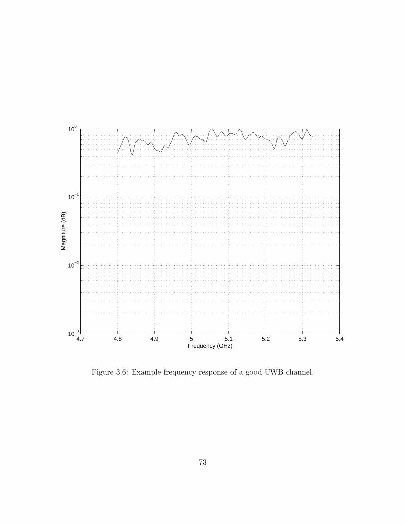
4.7 4.8 4.9 5 5.1 5.2 5.3 5.410
−3
10−2
10−1
100
Frequency (GHz)
Mag
nitu
re (
dB)
Figure 3.6: Example frequency response of a good UWB channel.
73
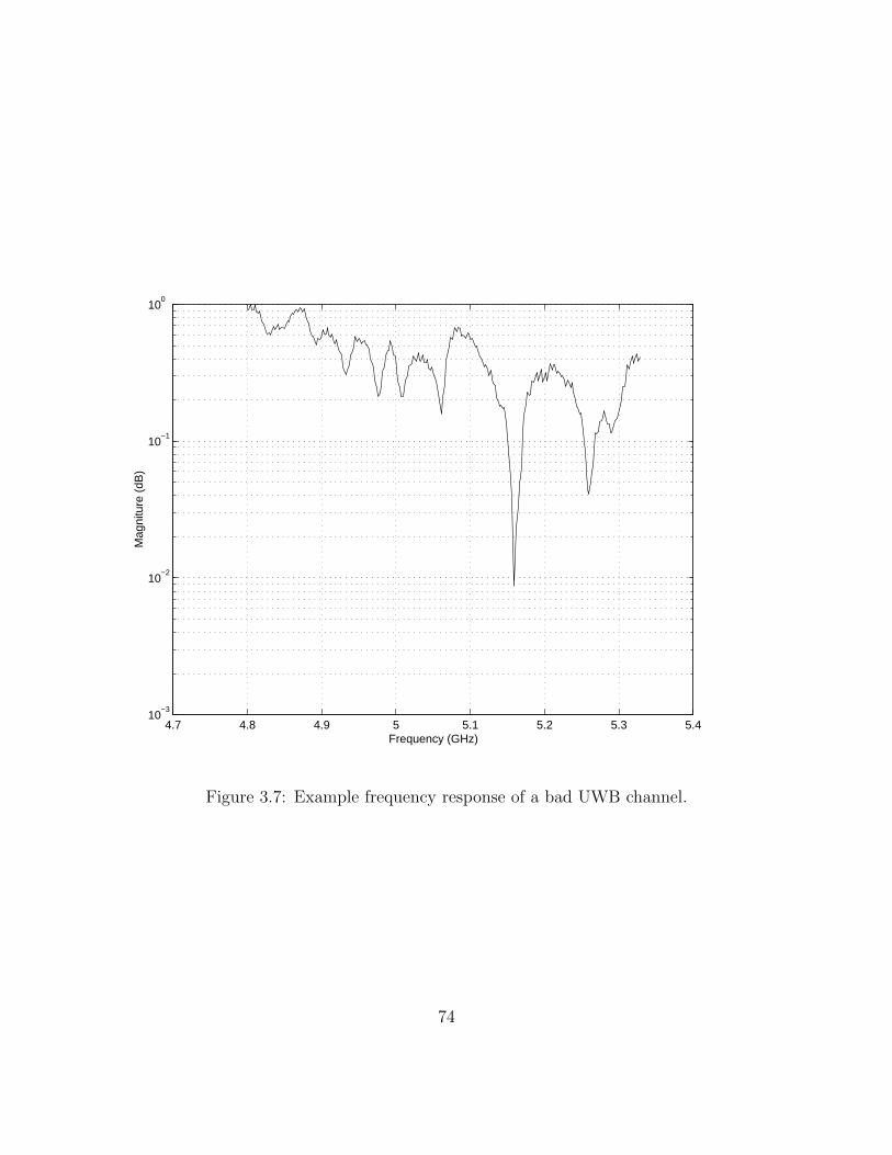
4.7 4.8 4.9 5 5.1 5.2 5.3 5.410
−3
10−2
10−1
100
Frequency (GHz)
Mag
nitu
re (
dB)
Figure 3.7: Example frequency response of a bad UWB channel.
74
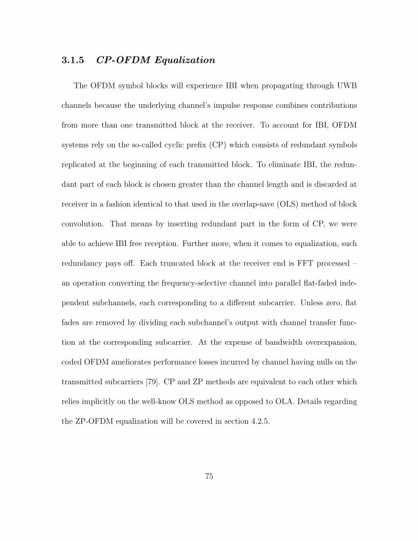
3.1.5 CP-OFDM Equalization
The OFDM symbol blocks will experience IBI when propagating through UWB
channels because the underlying channel’s impulse response combines contributions
from more than one transmitted block at the receiver. To account for IBI, OFDM
systems rely on the so-called cyclic prefix (CP) which consists of redundant symbols
replicated at the beginning of each transmitted block. To eliminate IBI, the redun-
dant part of each block is chosen greater than the channel length and is discarded at
receiver in a fashion identical to that used in the overlap-save (OLS) method of block
convolution. That means by inserting redundant part in the form of CP, we were
able to achieve IBI free reception. Further more, when it comes to equalization, such
redundancy pays off. Each truncated block at the receiver end is FFT processed –
an operation converting the frequency-selective channel into parallel flat-faded inde-
pendent subchannels, each corresponding to a different subcarrier. Unless zero, flat
fades are removed by dividing each subchannel’s output with channel transfer func-
tion at the corresponding subcarrier. At the expense of bandwidth overexpansion,
coded OFDM ameliorates performance losses incurred by channel having nulls on the
transmitted subcarriers [79]. CP and ZP methods are equivalent to each other which
relies implicitly on the well-know OLS method as opposed to OLA. Details regarding
the ZP-OFDM equalization will be covered in section 4.2.5.
75
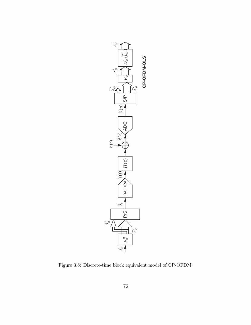
P/S
D
AC
+P
A
S/P
H
M
F
i M
s
i M
s ~
i cp
s ~
) ( z
H
n s ~
) (
~ t
s
) ( t
n
) (
~ t
x )
( ~
n x
i cp
x ~ i M
x ~
i M
x i M
s ˆ
M
F
) ~
(
' M
M
h
D
AD
C
CP
-OF
DM
-OL
S
Figure 3.8: Discrete-time block equivalent model of CP-OFDM.
76

OFDM signal block propagation through UWB channels can be modelled as a
FIR filter with the channel impulse response column vector h = [h0h1 · · · hM−1]T
and additive white Gaussian noise (AWGN) nn(i) of variance δ2n [79]. Let FM denote
the FFT matrix with (m, k)th entry e−j2πmk/M/√
M . Then, the IFFT matrix can be
denoted as F−1M = FH
M with (m, k)th entry ej2πmk/M/√
M to yield the so-called time
domain block vector siM = FH
MsiM , where (·)H denotes conjugate transposition. Then
in order to remove IBI, a cyclic prefix (CP) will be added onto time-domain block
vector as shown in figure 3.8.
Figure 3.8 depicts the baseband discrete-time block diagram of the CP-OFDM
system [79] [80] [81]. If we denote the signal vector siM and si
M as [siM(0)si
M(1) · · ·
siM(M − 1)]T and [si
M(0)siM(1) · · · si
M(M − 1)]T respectively, then adding a CP of
length D at the beginning of vector siM results a redundant block si
CP = [siM(M−D) ·
· · siM(M − 1)si
M(0)siM(1) · · · si
M(M − 1)]T which will be sent sequentially through the
channel. The total number of time-domain samples per transmitted block is, thus,
P = M + D. Consider the M × D matrix FCP formed by the last D columns of
FM . Defining FCP = [FCP ,FM ] as the P ×M matrix corresponding to the combined
multicarrier modulation and CP insertion, the block of symbols to be transmitted
can simply expressed as siCP = FCP si
M .
With ()T denoting transposition, the frequency-selective propagation will be mod-
elled as a FIR filter with channel impulse response column vector h = [h0 · · · hM−1]T
and additive white gaussian noise (AWGN) nin of variance σ2
n. In practice, we select
77

M ≥ D ≥ L, where L is the channel order (i.e., hi = 0,∀i > L). Then the ith
received symbol block is given by
xicp = HFcps
iM + HIBIFcps
i−1M + ni
P (III.4)
where H is the P ×P lower triangular Toeplitz filtering matrix and HIBI is the P ×P
upper triangular Toeplitz filtering matrix, which capture IBI, as follows [68]:
H =
h0 0 · · · 0 0
h1 h0 · · · 0 0
...
hL hL−1 · · · 0 0
0 hL · · · 0 0
...
0 0 · · · h0 0
0 0 · · · h1 h0
P×P
HIBI =
0 · · · 0 hL · · · h1
0 · · · 0 0 · · · h2
...
0 · · · 0 0 · · · hL
0 · · · 0 0 · · · 0
...
0 · · · 0 0 · · · 0
P×P
78

niP = [niP · · · niP+P−1]T denotes the AWGN vector.
Equalization of CP-OFDM transmission relies on the well-known property that
every circulant matrix can be diagonalized by post- (pre-) multiplication by (I)FFT
matrices [80]. After removing the CP at the receiver as indicated in figure 3.8, since
the channel order satisfies L ≤ D, equation III.4 reduces to
xiM = CM(h)FH
MsiM + ni
M (III.5)
where CM(h) is M ×M circulant matrix
CM(h) =
h0 0 · · · hL · · · h1
h1 h0 · · · 0 · · · h2
...
hL hL−1 · · · 0 · · · 0
...
0 0 · · · hL · · · h0
M×M
and niM = [niP+D · · · niP+P−1]T . The circulant matrix CM(h) can be diagonalized by
M ×M FFT matrix, which leads to
X iM = FMCM(h)FH
MsiM + FM ni
M
= diag(H0 · · ·HM−1)siM + FM ni
M
= DM(hM)siM + ni
M (III.6)
where hM = [H0 · · · HM−1]T =
√MFMh, with Hk = H(2πk/M) = ΣL
l=0hle−j2πkl/M
denoting the channel transfer function on the kth subcarrier, DM(hM) standing for
79
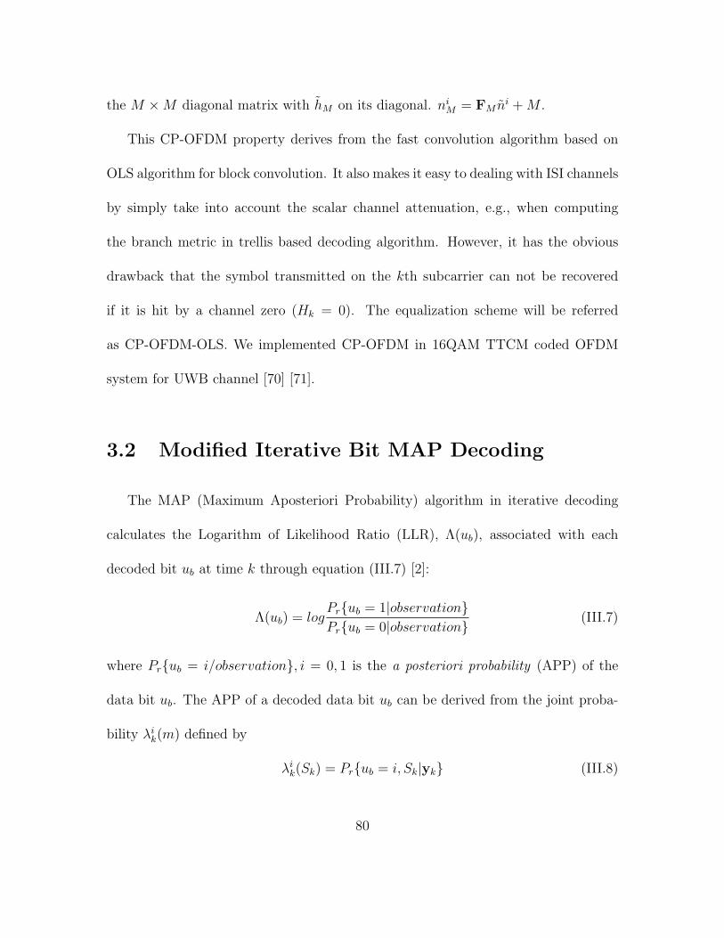
the M ×M diagonal matrix with hM on its diagonal. niM = FM ni + M .
This CP-OFDM property derives from the fast convolution algorithm based on
OLS algorithm for block convolution. It also makes it easy to dealing with ISI channels
by simply take into account the scalar channel attenuation, e.g., when computing
the branch metric in trellis based decoding algorithm. However, it has the obvious
drawback that the symbol transmitted on the kth subcarrier can not be recovered
if it is hit by a channel zero (Hk = 0). The equalization scheme will be referred
as CP-OFDM-OLS. We implemented CP-OFDM in 16QAM TTCM coded OFDM
system for UWB channel [70] [71].
3.2 Modified Iterative Bit MAP Decoding
The MAP (Maximum Aposteriori Probability) algorithm in iterative decoding
calculates the Logarithm of Likelihood Ratio (LLR), Λ(ub), associated with each
decoded bit ub at time k through equation (III.7) [2]:
Λ(ub) = logPr{ub = 1|observation}Pr{ub = 0|observation}
(III.7)
where Pr{ub = i/observation}, i = 0, 1 is the a posteriori probability (APP) of the
data bit ub. The APP of a decoded data bit ub can be derived from the joint proba-
bility λik(m) defined by
λik(Sk) = Pr{ub = i, Sk|yk} (III.8)
80

where Sk represents the encoder state at time k and yk is the received channel symbol.
Thus, the APP of a decoded data bit ub is equal to
Pr{ub = i|yk} =∑Sk
λik(Sk), i = 0, 1 (III.9)
From relations (III.7) and (III.9), the LLR Λ(ub) associated with a decoded bit ub
can be written as
Λ(ub) = log
∑Sk
λ1k(Sk)∑
Sk
λ0k(Sk)
(III.10)
Finally the decoder can make a decision by comparing Λ(ub) to a threshold equal to
zero
ub = 1 ifΛ(ub) > 0
ub = 0 ifΛ(ub) < 0
The joint probability λik(Sk) can be rewritten using Bayes rule
λik(Sk) =
Pr{ub = i, Sk,yk1 ,y
Nk+1}
Pr{yk1 ,y
Nk+1}
=Pr{ub = i, Sk,y
k1}
Pr{yk1}
·Pr{yN
k+1|ub = i, Sk,yk1}
Pr{yNk+1|yk
1}
in which we assume the information symbol sequence {uk} is made up of Nu inde-
pendent input symbols uk with K input bits (i.e. ub, b = 1 . . . K) in each uk and
take into account that events after time k are not influenced by observations yk1 and
symbol uk if encoder state Sk is known. For easy computation of the probability
81
λik(Sk), probability functions αk(Sk), βk(Sk) and γi(yk, Sk−1, Sk) are introduced as
follows [61]:
αk(Sk) =Pr{ub = i, Sk,y
k1}Pr{ub = i, Sk|yk
1}Pr{yk
1}
βk(Sk) =Pr{yN
k+1|Sk}Pr{yN
k+1|yk1}
γi(yk, Sk−1, Sk) = Pr{ub = i,yk1 , Sk|Sk−1}
Then λik(Sk) can be simplified as:
λik(Sk) = αk(Sk)βk(Sk) (III.11)
The probabilities αk(Sk) and βk(Sk) can be recursively calculated from probability
γi(yk, Sk−1, Sk) through
αk(Sk) =
∑Sk−1
1∑j=0
γi(yk, Sk−1, Sk)αjk−1(Sk−1)
∑Sk
∑Sk−1
1∑i=0
1∑j=0
γi(yk, Sk−1, Sk)αjk−1(Sk−1)
βk(Sk) =
∑Sk−1
1∑j=0
γi(yk+1, Sk, Sk+1)βjk+1(Sk+1)
∑Sk+1
∑Sk
1∑i=0
1∑j=0
γi(yk+1, Sk, Sk+1)αjk(Sk)
and γi(yk, Sk−1, Sk) can be determined from transition probabilities of the encoder
trellis and the channel, which is given by
γi(yk, Sk−1, Sk) = p(yk|ub = i, Sk−1, Sk)
×q(ub = i|Sk−1, Sk)
×π(Sk|Sk−1) (III.12)
82

p(·|·) is the channel transition probability, q(·|·) is either 1 or 0 depending on whether
the ith bit is associated with transition from Sk−1 to Sk or not, and π(·|·) is the state
transition probability that uses the extrinsic information of information uk.
Using LLR Λ(ub) definition (III.10) and relations among λik, αk, βk and γi we
obtain
Λ(ub) = log
∑Sk
∑Sk−1
γ1(yk, Sk−1, Sk)αk−1(Sk−1)βk(Sk)∑Sk
∑Sk−1
γ0(yk, Sk−1, Sk)αk−1(Sk−1)βk(Sk)(III.13)
It was proved in [2] that the LLR Λ(ub) associated with each decoded bit ub is the
sum of the LLR of ub at the decoder input and of another information called extrinsic
information generated by the decoder.
Divsalar [59] for the first time described an iterative decoding scheme for q parallel
concatenated convolutional codes based on approximating the optimum bit decision
rule by considering the combination of interleaver and the trellis encoder as a block
encoder. The scheme is based on solving a set of nonlinear equations given by (q = 2
is used here to illustrate the concept, [82] [59])
L1b = log
∑u:ub=1 P (y1|u)
∏j 6=b eujL2j∑
u:ub=0 P (y1|u)∏
j 6=b eujL2j
L2b = log
∑u:ub=1 P (y2|u)
∏j 6=b eujL1j∑
u:ub=0 P (y2|u)∏
j 6=b eujL1j
for b = 1, 2, ..., K representing b input bits per constituent encoder, where L1j are
the extrinsic information and yq are the received observation vectors corresponding
to the qth trellis code. The final decision is then based on Lb = L1b + L2b, which
passed through a hard limiter with zero threshold.
83

The above set of nonlinear equations are derived from the optimum bit decision
rule
Lb = log
∑u:ub=1 P (y1|u)P (y2|u)∑u:ub=0 P (y1|u)P (y2|u)
(III.14)
using the following approximation
P (u|y1) ≈N∏
b=1
eubL1b
1 + eL1b
, P (u|y2) ≈N∏
b=1
eubL2b
1 + eL2b
(III.15)
The nonlinear equations in equation (III.14) can be solved by using an iterative
procedure
L(m+1)1b = log
∑u:ub=1 P (y1|u)
∏j 6=b eujL
(m)2j∑
u:ub=0 P (y1|u)∏
j 6=b eujL(m)2j
(III.16)
on m for b = 1, 2, ..., K. Similar recursions hold for L(m+1)2b . The recursion starts with
the initial condition L(0)1 = L
(0)2 = 0. The LLR of a symbol u given the observation y
is calculated first using the symbol MAP algorithm
λ(u) = logP (u|y)
P (0|y)(III.17)
where 0 corresponds to the all-zero symbol. The symbol MAP algorithm [61] can be
used to calculate Eq. (III.17), as shown in Figure 3.9 [82]. Then the LLR of the bth
bit within the symbol can be obtained by
Lb = log
∑u:ub=1 eλ(u)∑u:ub=0 eλ(u)
(III.18)
The symbol a priori probabilities needed in the symbol MAP algorithm, which will
be used in branch transition probability calculation, can be obtained by
P (u = (u1, u2, ..., uK)) =K∏
b=1
eubLb
1 + eLb
(III.19)
84

with the assumption that the extrinsic bit reliabilities coming from the other decoder
are independent.
In our case, we apply the turbo iterative MAP decoding scheme in [2] [61] [82] [83],
and make certain modifications to fit our concatenated encoder structure. Since our
parity-concatenated encoder structure consists of a TCM inner code and simplest
parity-check outer code functioning as repeaters, we only need one bit MAP decoder
for the inner code decoding. The outer code decoding can be interpreted as extrinsic
information exchange. Therefore, the standard iterative decoder for TTCM can be
modified into figure 3.10.
The bit MAP decoder computes the a posteriori probabilities P (ub|y, u) (y is the
received channel symbol and u is the result from previous iteration), or equivalently
the log-likelihood ratio Λ(ub) = log(P (ub = 1|y, u)/P (ub = 0|y, u)). Then, the
extrinsic information Le(ub)out is extracted from Le(ub)out = Λ(ub)−Lc(ub)−Le(ub)in
to avoid information being used repeatedly. It will be supplied to the parity-check
decoder. The outer parity-check decoder updates the Le(ub)out into Le(ub)in according
to parity check constraints between information bits and supplies it to the bit MAP
decoder for the next iteration. Le(ub)in is the extrinsic information, which is used as
a priori probability for branch metric computation in MAP decoding process. Lc(ub)
is the channel reliability for each ub.
85

L
1
^
λ (u)
L1kL2
(m)^
(m)L1^
(m+1)L^
2π π
λ (u) (m+1)
2k
L
Y
Y
2
1
DecodedBits
Symbol
SymbolMAP1
MAP2−122
BitReliabilityCalculation
BitReliabilityCalculation
DELAY
DELAY
Figure 3.9: Iterative (turbo) decoder structure for two trellis codes
LL
b
ine(ub)
Extraction
Extrinsic Info.
Extrinsic Info.Updating
DecoderBit MAP
Received Signal
e(ub)out
Final IterationOutput atChannel Information
and/or
)(u
Figure 3.10: Block diagram of the iterative decoder.
86

Since half of the systematic bits from the inner TCM encoder are punctured,
it seems that we can only get channel transition probability for the remaining half
of the information bits and parity check bits. However, the punctured information
bits are the parity checks of those systematic bits at the encoder outputs except
being interleaved. So we can always find the channel transition probability for the
punctured information bits through the un-punctured part. The extrinsic information
value associated with π(·/·) in (III.12) is given as the logarithm format:
Le(ub) = logP (ub = 1)
P (ub = 0)(III.20)
If q(ub = 1/Sk−1, Sk) = 1, then
π(Sk/Sk−1) =eLe(ub)
1 + eLe(ub)(III.21)
otherwise
π(Sk/Sk−1) =1
1 + eLe(ub)(III.22)
3.3 System Performance Analysis
3.3.1 Density Evolution for TTCM
Convergence analysis of iterative decoding algorithms for turbo codes has received
much attention recently due to its useful application to predicting code performance,
its ability to provide insights into the encoder structure, and its usefulness in helping
87

with the code design. Turbo trellis-coded modulation conjoins signal mapping tech-
niques, such as Ungerboeck’s signal space partition, with turbo coding, to achieve
significant coding gains without increasing bandwidth. however, the need for signal
mapping makes the encoder structure more complex to design and analyze than bi-
nary turbo codes. Hence, the convergence analysis is a very important tool for design
and comparison between TTCM schemes. Several models have been proposed to an-
alyze the convergence of iterative decoders. In particular, the extrinsic information
transfer (EXIT) method [84] [85] [86] has created a lot interest.
The density evolution method in [87] has been used to confirm the simulation. We
approximate the extrinsic information as a Gaussian variable whose mean is equal
to half of the variance. In each iteration, we compute the average mean of the ex-
trinsic information and then regenerate the extrinsic information as an independent
Gaussian variable. Thus, the dependence between the extrinsic information bits has
been wiped out. This is the main difference between density evolution and simula-
tion. Since TCM is typically irregular, density evolution using the all zero sequence
may be biased. So we need to consider both 0-bit and 1-bit as input which could
bring negative mean according to the definition of extrinsic information in (III.20).
We examine the mean of extrinsic information using tens of thousands of randomly
generated bit sequences and make it always positive regardless of bit sequences by
weighting through the sign of the bit. Such mean can be easily traced by two decoding
88

trajectories in the density evolution chart, i.e.,
µLe = Le(ub)(2ub − 1) (III.23)
where overbar denotes the average. For UWB channels, we then average it over more
than 2000 UWB channels.
Procedure of density evolution can be summarized as follows:
(1) Before the first iteration starts, all the extrinsic information is set to be zero.
(2) We divide each decoding process into two halves: one half-iteration for TCM
followed by another half-iteration for parity check codes. For each half-iteration
we can calculate the updated extrinsic information through decoding. Using tens
of thousands of simulation we can get the mean of the densities of those updated
extrinsic information using (III.23).
(3) Further, we assume the density to be Gaussian with the mean computed in
(III.23) and the variance equal to twice of the mean based on density symmetry
condition [86]. Then, we regenerate the extrinsic information as independent
Gaussian variable for the next half-iteration.
(4) During each half-iteration, SNR is estimated as half of the mean of extrinsic
information. SNR before and after each half-iteration then can be tracked in the
density evolution chart as in this paper.
89

Density evolution can be used to determine the threshold, which is the minimum SNR
for the decoder to converge assuming infinite block length. In density evolution chart,
as long as the SNR is above the threshold, these two constituent transfer curves will
never intersect, which means convergence in the limiting case. In figure 3.11, we show
density evolution for OFDM systems using 16QAM on Gaussian and UWB fading
channels. For Gaussian channels, we find the threshold is 2.6dB and show the EXIT
chart for Eb/No = 2.8dB. On UWB channels, we found that if we take average over
all 2000 channels, then EXIT chart shows the clear case of convergence (see curves
with solid squares in figure 3.11). However, if we run EXIT over each individual
channel instance, then some channel instances require much large SNRs to allow
iterative decoding to converge to correct codewords. For example, at Eb/No = 5.5dB,
about 2% of the channels are difficult to converge (see curves with crosses in figure
3.11). We call them “bad” channels. When Eb/No is small, the percentage of worst
channels increases significantly. For example, when Eb/No = 4.5dB, about 20% of
channels are bad. Good performance can only be achieved unless the interleave can
fully randomize the extrinsic information over all channels. If the bits of a packet
are interleaved over a number of channels containing significant amount of “bad”
channels, then the performance will be much poorer. This is the main reason that
the packet error rate curve for UWB could not drop sharply as those on AWGN
channels.
90

0 1 2 3 4 50
0.5
1
1.5
2
2.5
3
3.5
4
4.5
5
SNR1_in,SNR2_out
SN
R1_
out,S
NR
2_in
solid with square:UWB 5.5dB(average case )
solid with +:UWB 5.5dB(2% worst case)
solid with o:Gaussian 2.8dB
UWB/OFDM/16QAM
Figure 3.11: Density evolution for 16QAM/OFDM on AWGN and UWB channels.
91

Figure 3.12 presents the density evolution analysis for OFDM system using 64QAM
on Gaussian and UWB fading channles. For Gaussian channels, we find the threshold
is 3.7dB and show the EXIT chart for Eb/No = 4.2dB. For UWB channels, when
we set Eb/No = 9.2dB, about 2% of the channels are bad.
92

0 1 2 3 4 50
0.5
1
1.5
2
2.5
3
3.5
4
4.5
5
SNR1_in,SNR2_out
SN
R1_
out,S
NR
2_in
UWB/OFDM/64QAM
solid with square:UWB 9.2dB(average case )
solid with o:Gaussian 4.2dB
solid with +:UWB 9.2dB(2% worst case)
Figure 3.12: Density evolution for 64QAM/OFDM on AWGN and UWB channels.
93

3.3.2 Bound Performance for TTCM
There are a considerable amount of research has addressed the bound performance
evaluation of different codes [48] [53] [88]- [102], which cover the code type from block
codes, convolutional codes, turbo codes, TCM codes, and concatenated codes. Dif-
ferent approaches to evaluate the performance of TCM codes or turbo codes have
been suggested in [53] [92]- [102]. Duman and Salehi in [93] provide the performance
analysis for 16QAM turbo coded modulation system. All of the above turbo type
code performance evaluation is based on conventional turbo structure and then finds
the average performance bounds (averaged over all possible interleavers). Our en-
coder functions as a Turbo TCM as shown in figure 2.15 for the 16QAM case, but
due to the multiple input streams and the punctured systematic bits, it’s hard to
use the evaluation method proposed in [93]. Here we try to explore the exhaustive
enumeration of TTCM codewords to confirm the code performance.
For maximum likelihood decoding and transmission over an AWGN channel, the
upper and lower union bounds for bit error rate Pb at high signal-to-noise ratios can
be written as [94] [7] [93] [89] [90]:
Pb ≤∞∑
di=dmin
Bi
NAiQ
√d2
i
2N0
(III.24)
Pb ≥Bdmin
NAdmin
Q
√d2
dmin
2N0
(III.25)
where Ai is the numbers of error paths with the Euclidean distance di, Bi is the average
94
number of bit errors occurring on paths with di, and Adminand Bdmin
correspond to
Ai and Bi when di = dmin, N is the input package length or interleaver length, N0 is
the single-sided spectral noise density of the AWGN channel.
The most difficult task in calculating the union bounds for turbo TCM is to find
Ai, Bi and di of the error path. More precisely the most difficult part is to find the
error path since we do not have a simple trellis structure as in [92] to traverse because
there are two constituent encoders connected by two interleavers at the inputs. So
we need to consider a hyper-trellis similar to [7] to examine the full dynamics of the
turbo TCM code.
Turbo TCM code is irregular. We examine error events of N steps. Each error
path should be labelled by the input bits and output parity check bit, which is the
IRWEF in each step, such as ACk(w1, w2, z), where w1, w2 are the weights of u1 and
u2, z is the weight of parity check bit, and Ck identifies the 1st or 2nd constituent
encoder. Since the two encoders are identical, we only need to work this out for one
encoder and obtain the other accordingly. Then, we combine two error paths, one
from C1 and another from C2, which have the same value in cross summation of w1
and w2, where cross summation (∑
w1) of C1 should be equal to∑
w2 of C2 and∑w2 of C1 should be equal to
∑w1 of C2 since the positions of interleaved u1 and u2
are changed before the second encoder. After mapping the IRWEF of the combined
error path, we can easily find the squared Euclidean distance of the error path from
the transmitted path.
95

Two points requiring attention are: (1) The error paths from two constituent
encoders do not have to diverge the starting state from the first step and merge back
the ended state in the last step simultaneously when being combined, since the final
error path requires only one different output at each step to differ from the correct
path, as long as two constituent error paths have same cross summation of w1, w2. (2)
Since there are two interleavers at the inputs, assuming the interleavers are uniform,
the probability of the resulted error path will be
Ai(w1, w2, di) =AC1(w1, w2, di)A
C2(w2, w1, di) N
w1
N
w2
(III.26)
where AC1(w1, w2, di) and AC2(w2, w1, di) are the number of the error paths from
encoder C1 and C2 corresponding to the squared Euclidean distance di of the combined
error path with information weight w1 and w2. So the resulted average error bits on
path (w1, w2, di) is Bi = w1 + w2.
For arbitrary inputs, we can first find the correct transmission path, and then
only record combined paths which are different from the correct one. The bound
performance for interleaver size of 10 is given in figure 3.13. We note the consistency
of the bound with the simulation results.
96
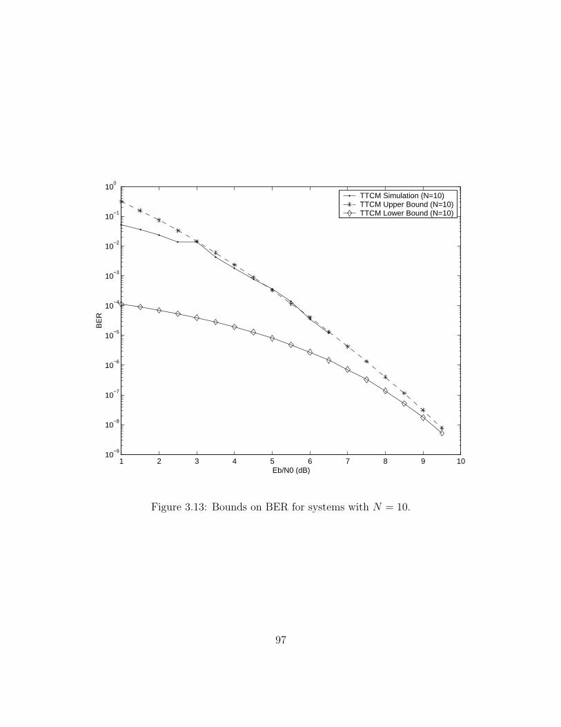
1 2 3 4 5 6 7 8 9 1010
−9
10−8
10−7
10−6
10−5
10−4
10−3
10−2
10−1
100
Eb/N0 (dB)
BE
R
TTCM Simulation (N=10)TTCM Upper Bound (N=10)TTCM Lower Bound (N=10)
Figure 3.13: Bounds on BER for systems with N = 10.
97
3.4 Numerical Results
The large bandwidth of UWB waveforms significantly increases the ability of the
receiver to resolve the different reflections in the channel. OFDM is one of two basic
solutions for inter-symbol interference (ISI) removal and efficiently capturing multi-
path energy in highly dispersive UWB channels and delivering high data rate trans-
mission. The IEEE 802.15 task group came up with a high data rate WPAN with
data rate from 55 Mbps to 480 Mbps using punctured convolutional coded OFDM
modulation [39]. we are examining the possibility of improving the proposed system
using Turbo TCM with QAM constellation for higher data rate transmission. The
study shows that the system can offer much higher spectral efficiency, for example,
1.2 Gbps, which is 2.5 times higher than the current proposed system. Results have
been confirmed by density evolution in 3.3.1.
The performance of the proposed coding/decoding scheme is evaluated and ap-
plied to the OFDM systems for UWB channels. A similar simulation has been done
over AWGN channels for performance comparison. System level simulations were
performed to estimate the bit error rate (BER) and packet error rate (PER) perfor-
mance. Table 1 shows a list of key OFDM parameters used in our simulations. The
system is assumed to be perfectly synchronized.
98

Table 3.2: Coded OFDM system parameters
Info. Data Rate 640Mbps / 1.2Gbps
Constellation 16QAM / 64QAM
16-state TCM code (23,35,27) / (23,35,33,37,31)
FFT size 128
Data Tones 100
System Bandwidth 528MHz
Subcarrier Frequency Spacing 4.125MHz
IFFT/FFT Period 242.42ns
Cyclic Prefix Duration 60.61ns
Gaurd Interval Duration 9.47ns
Symbol Interval 312.5ns
Time-domain Spreading Yes
Multi-path Tolerance 60.6ns
UWB Channel Model AR model
OFDM Equalization CP-OFDM / ZP-OFDM
99

3.4.1 640Mbps OFDM System Over UWB Channel
A 16-state TCM code with octal notation (23,35,27) is chosen with 16QAM mod-
ulation. The resultant data rate for OFDM/UWB system is 640Mbps. Simulation
results are averaged over 2000 packets with a payload of 1k bytes. There are 2000
different UWB channel realizations were involved in the simulation.
Figure 3.14 shows the BER performance of the coded 16QAM OFDM system and
uncoded OFDM system in both UWB and AWGN channels as a function of Eb/N0.
Uncoded modulation scheme is QPSK in order to keep same system coding rate. For
UWB channels, the Line of Sight (LOS) distance between the transmitter and receiver
is 10m. To measure BER at each point, we simulated up to 1.64× 107 bits, which is
2000 packets × 41 OFDM symbols/packet × 100 QAM symbols/OFDM symbol × 2
bits/QAM symbol. The coded OFDM curve shows a big performance improvement
over uncoded OFDM, especially on UWB channels. Furthermore, a BER of 8× 10⁻⁶
is obtained at Eb/N0 = 6.7dB.
Figure 3.15 describes the PER performance of the 640Mbps coded OFDM system
and uncoded case over UWB and AWGN channels. The low PER of 0.036 is obtained
at Eb/N0 = 6.7dB for coded OFDM over 10m UWB channels.
100

0 2 4 6 8 10 12 14 16 1810
−6
10−5
10−4
10−3
10−2
10−1
100
Eb/N0 (dB)
BE
R
AWGN−coded−16QAMAWGN−uncoded−QPSKUWB−coded−16QAMUWB−uncoded−QPSK
Figure 3.14: BER of OFDM/16QAM over UWB and AWGN channel.
101

0 2 4 6 8 10 12 14 16 1810
−2
10−1
100
Eb/N0 (dB)
PE
R
AWGN−coded−16QAMAWGN−uncoded−QPSKUWB−coded−16QAMUWB−uncoded−QPSK
Figure 3.15: PER of OFDM/16QAM over UWB and AWGN channel.
102

3.4.2 1.2Gbps OFDM System Over UWB Channel
A 16-state TCM code with octal notation (23,35,33,37,31) is chosen for 64QAM
modulation. The resultant data rate for OFDM/UWB is 1.2Gbps, which is 2.5 times
of the data rate for current OFDM/UWB system. All simulation results are averaged
over 2000 packets with a payload of 2k bytes for 1.2Gbps system. Similarly, there are
2000 different UWB channel realizations were involved in the simulation.
The BER performance for 64QAM coded OFDM system and 16QAM uncoded
OFDM system is illustrated in figure 3.16. Again uncoded modulation scheme is lower
than coded modulation scheme to keep the same system coding rate. There are 3.28×
107 (2000 packets × 41 OFDM symbols/packet × 100 QAM symbols/OFDM symbol
× 4 bits/QAM symbol) random bits simulated to measure the BER. The LOS dis-
tance of the UWB channel is 10m. The simulation results indicate a BER of 2.3×10⁻⁵
at Eb/N0 = 10.7dB for 1.2Gbps coded OFDM system over UWB channels. Figure
3.17 presents the PER performance for the same situation, reporting a low PER of
0.011 at Eb/N0 = 10.7dB for 1.2Gbps coded OFDM over UWB channels.
103

2 4 6 8 10 12 14 16 1810
−6
10−5
10−4
10−3
10−2
10−1
100
Eb/N0 (dB)
BE
R
AWGN−coded−64QAMAWGN−uncoded−16QAMUWB−coded−64QAMUWB−uncoded−16QAM
Figure 3.16: BER of OFDM/64QAM over UWB and AWGN channel.
104

2 4 6 8 10 12 14 16 1810
−2
10−1
100
Eb/N0 (dB)
PE
R
AWGN−coded−64QAMAWGN−uncoded−16QAMUWB−coded−64QAMUWB−uncoded−16QAM
Figure 3.17: PER of OFDM/64QAM over UWB and AWGN channel.
105

CHAPTER IV
TURBO TCM CODED OFDM
SYSTEM FOR POWERLINE
CHANNELS
4.1 Introduction of Powerline Communications
Powerline communications stands for the use of power supply grid for communi-
cation purpose. Power line network has very extensive infrastructure in nearly each
building. Because of that fact the use of this network for transmission of data in ad-
dition to power supply has gained a lot of attention. Since power line was devised for
transmission of power at 50-60 Hz and at most 400 Hz, the use this medium for data
transmission, at high frequencies, presents some technically challenging problems.
106

Besides large attenuation, power line is one of the most electrically contaminated
environments, which makes communication extremely difficult. Further more the re-
strictions imposed on the use of various frequency bands in the power line spectrum
limit the achievable data rates.
High-speed data communication over low-tension power lines has recently gained
lot of attention. This is fueled by the unparalleled growth of the Internet, which has
created accelerating demand for digital telecommunications. High bandwidth digital
devices are designed to exploit this market. More specifically, these devices use the
existing power line infrastructure within the apartment, office or school building for
providing a local area network (LAN) to interconnect various digital devices. It has
to be noted that the existing infrastructure for communications like telephone line,
Cable TV has very few outlets inside the buildings. By use of gateways between
these and Power line LANs a variety of services can be offered to customers. Some
of the applications, from in-the-home applications to to-the-home applications, in-
clude high-speed Internet access, multimedia, smart appliances/remote control, home
automation and security; data back up, telecommunications, entertainment and IP-
telephony. Powerline communications allows you to plug in, and simply connect.
High bandwidth digital devices for communication on power line use the frequency
band between 1 MHz and 30 MHz. In contrast to low bandwidth digital devices, no
regulatory standards have been developed for this region of the spectrum. Devices
using this unlicensed band need to be compliant with the radiation emission limits
107

imposed by the regulatory bodies. It should be noted that internationally agreed,
distress, broadcast, citizen band and amateur radio frequencies also occupy this por-
tion of the spectrum. Hence, the technologies being developed for high-speed digital
communication over power line should have the ability to mask certain frequency
bands for future compatibility. In the section that follows gives a brief overview of
power line channel characteristics in the frequency band between 1 MHz and 30 MHz.
Since the power line is not designed for communication purpose, the channel ex-
hibits unfavorable transmission properties, such as frequency-selective, narrowband
interference, impulse noise and attenuation increase with length and frequency. High
bandwidth digital devices communicating on power line devices need to use power-
ful error correction coding along with appropriate modulation techniques to improve
these impairments. The choice of modulation scheme is dependent on the nature of
physical medium on which it has to operate. Modulation scheme for use on power
line should have the following desirable properties:
1. Ability to over come non-linear channel characteristics: Power line has a very
non-linear channel characteristics. This would make equalization very complex
and expensive, if not impossible, for data rates above 10 Mbps with single carrier
modulation. The modulation technique for use on power line should have the
ability to overcome such non-linearities without the need for a highly complicated
equalization;
108

2. Ability to over come multipath spread: Impedance mismatch on power lines
results in echo signal causing delay spread of the order of 1ms. The modulation
technique for use on power line should have the inherent ability to over come
such multipath effect;
3. Ability to adjust dynamically: Power line channel characteristics change dynam-
ically as the load on the power supply varies. The modulation technique for use
on power line should have the ability to track such changes without involving
large overhead or complexity;
4. Ability to mask certain frequencies: Power line communications equipment use
unlicensed frequency band. However it is likely that in the near future various
regulatory rules could be developed for this frequency bands also. Hence it
is highly desirable to have a modulation technique that could selectively mask
certain frequency bands. This property would help in future compatibility and
marketability of the product globally.
A modulation scheme that has all these desirable properties is Orthogonal Frequency
Division Multiplexing (OFDM). OFDM is generally view as a collection of transmis-
sion techniques. When applied in wireless environment it is called OFDM. However
in a wired environment the term Discrete Multi Tone (DMT) is more commonly
used. OFDM is currently used in the European Digital Audio Broadcast (DAB)
standards. Several DAB systems proposed for North America are also based on
109

OFDM. OFDM under the name DMT has also attracted a great deal of attention as
an efficient technology for high-speed transmission on the existing telephone networks
(e.g. Asymmetric Digital Subscriber Loop or ADSL).
4.2 OFDM System For Power Line Channel
Here we will re-state some advantages of OFDM:
1. Very good at mitigating the effects of time-dispersion;
2. Very good at mitigating the effect of in-band narrowband interference;
3. High bandwidth efficiency and scalable to high data rates
4. Flexible and can be made adaptive; different modulation schemes for subcarriers,
bit loading, adaptable bandwidth/data rates possible
5. It makes the Inter Carrier Interference (ICI) zero even in the presence of time dis-
persion by maintaining orthogonality. It also acts like a guard interval removing
Inter Symbol Interference (ISI);
6. It Does not require channel equalization.
All of above mentioned merits make OFDM a good modulation technique in powerline
communications. HomePlug networking specifications are the globally recognized
standards for high-speed powerline networking. We will investigate the performance
110
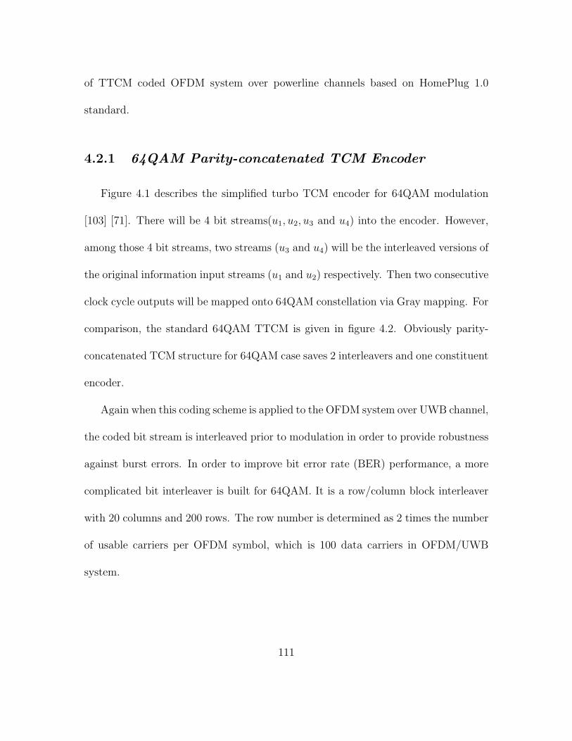
of TTCM coded OFDM system over powerline channels based on HomePlug 1.0
standard.
4.2.1 64QAM Parity-concatenated TCM Encoder
Figure 4.1 describes the simplified turbo TCM encoder for 64QAM modulation
[103] [71]. There will be 4 bit streams(u1, u2, u3 and u4) into the encoder. However,
among those 4 bit streams, two streams (u3 and u4) will be the interleaved versions of
the original information input streams (u1 and u2) respectively. Then two consecutive
clock cycle outputs will be mapped onto 64QAM constellation via Gray mapping. For
comparison, the standard 64QAM TTCM is given in figure 4.2. Obviously parity-
concatenated TCM structure for 64QAM case saves 2 interleavers and one constituent
encoder.
Again when this coding scheme is applied to the OFDM system over UWB channel,
the coded bit stream is interleaved prior to modulation in order to provide robustness
against burst errors. In order to improve bit error rate (BER) performance, a more
complicated bit interleaver is built for 64QAM. It is a row/column block interleaver
with 20 columns and 200 rows. The row number is determined as 2 times the number
of usable carriers per OFDM symbol, which is 100 data carriers in OFDM/UWB
system.
111

.D
DD
D
. . . .
. . . .
. .
. .. .
vv
u u
2
uu
v0k
v v
1
124 3
QA
M64
2 1k2k0k+1
k+1 1k+1
v
Figure 4.1: Parity-concatenated TCM encoder, 64QAM
112

Figure 4.2: Turbo TCM encoder, 64QAM
113

The interleaver function can be described mathematically as follows. Let D be the
number of bits to be interleaved (D = (number of carriers)*(Bits per carrier)*(number
of OFDM symbols)). In this 64QAM OFDM system, D can be a maximum of 24000
bits (= 100 × 6 × 40). Then define LIM = D/6, which is 4000 in this case, W =
number of columns = 20, and S = 8 denoting a shift constant. Denote by Vin the
non-interleaved input vector and by Vout the interleaved output vector. The function
k[i] below describe the one-to-one mapping between the index k[i] of Vin and index
of i of Vout, such that Vout(i) = Vin(k[i]).
k[i] = mod(W×(i+S×floor(W × i
LIM))−(LIM−1)×floor(
W × i
LIM), LIM), i = 0 . . . , LIM−1
(IV.1)
where mod(x,y) returns the remainder on dividing x by y with the result having the
same sign as x. Since we use 64QAM modulation here, the mapping function k[i] shall
be applied 6 times, each time to LIM bits in Vin. Then 6 bits from 6 length LIM output
vectors each time shall be combined to map one point in 64QAM constellation.
Alternatively, the interleaver procedure can be described by the way the data
is written into and read out of an ”interleaver matrix”. This is illustrated below
through figure 4.3. According to WPAN standard, maximum of 40 OFDM symbols
are contained in one Physical Layer (PHY) transmission block. So the interleaver
matrix is 200 × 20 bits. The number of rows used is equal to 2 times the number
of data carriers in one OFDM symbol. The non-interleaved data is written into this
114
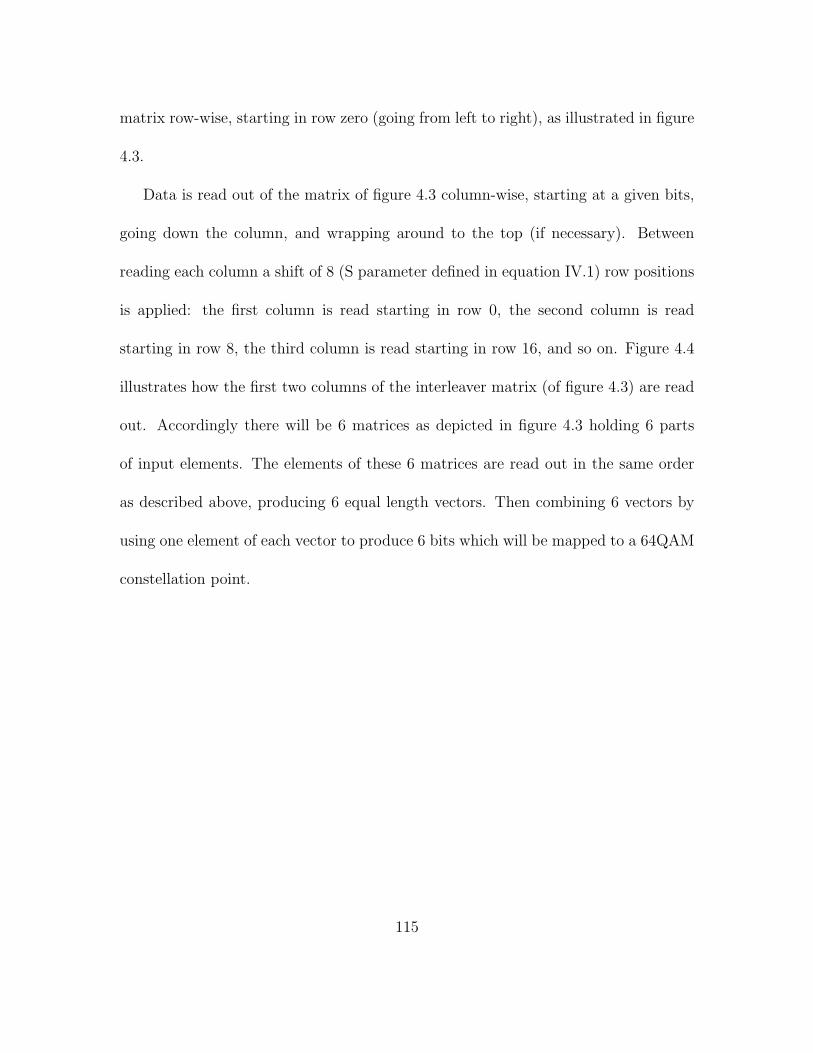
matrix row-wise, starting in row zero (going from left to right), as illustrated in figure
4.3.
Data is read out of the matrix of figure 4.3 column-wise, starting at a given bits,
going down the column, and wrapping around to the top (if necessary). Between
reading each column a shift of 8 (S parameter defined in equation IV.1) row positions
is applied: the first column is read starting in row 0, the second column is read
starting in row 8, the third column is read starting in row 16, and so on. Figure 4.4
illustrates how the first two columns of the interleaver matrix (of figure 4.3) are read
out. Accordingly there will be 6 matrices as depicted in figure 4.3 holding 6 parts
of input elements. The elements of these 6 matrices are read out in the same order
as described above, producing 6 equal length vectors. Then combining 6 vectors by
using one element of each vector to produce 6 bits which will be mapped to a 64QAM
constellation point.
115

Figure 4.3: Bit interleaver
116

0 99
4
3 2
1
0 99
4
3 2
1
0 99
4
3 2
1
0 20
40
19
80
60
80
. .
. .
. .
. .
. .
. .
2000
20
20
2040
20
60
2080
39
80
161
181
201
221
241
2141
0 99
4
3 2
1 .
. .
. 21
61
2181
22
01
2221
22
41
141
Vec
tor
#1
Sm
bol 1
Vec
tor
#1
Sm
bol 2
Vec
tor
#1
Sm
bol 3
Vec
tor
#1
Sm
bol 4
Figure 4.4: Interleaved data on first 4 symbols
117
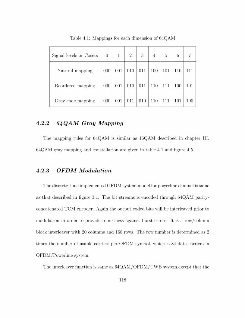
Table 4.1: Mappings for each dimension of 64QAM
Signal levels or Cosets 0 1 2 3 4 5 6 7
Natural mapping 000 001 010 011 100 101 110 111
Reordered mapping 000 001 010 011 110 111 100 101
Gray code mapping 000 001 011 010 110 111 101 100
4.2.2 64QAM Gray Mapping
The mapping rules for 64QAM is similar as 16QAM described in chapter III.
64QAM gray mapping and constellation are given in table 4.1 and figure 4.5.
4.2.3 OFDM Modulation
The discrete-time implemented OFDM system model for powerline channel is same
as that described in figure 3.1. The bit streams is encoded through 64QAM parity-
concatenated TCM encoder. Again the output coded bits will be interleaved prior to
modulation in order to provide robustness against burst errors. It is a row/column
block interleaver with 20 columns and 168 rows. The row number is determined as 2
times the number of usable carriers per OFDM symbol, which is 84 data carriers in
OFDM/Powerline system.
The interleaver function is same as 64QAM/OFDM/UWB system,except that the
118

Figure 4.5: 64QAM constellation
119
parameter D, which is the number of bits to be interleaved, equals to (numberofcarriers)×
(Bitspercarrier) × (numberofOFDMsymbols) = 84 × 4 × 40 = 13440). Then ac-
cordingly LIM = D/6, which is 2240 in this case, W = number of columns = 20, and
S = 8 denoting a shift constant between reading each column from row/column block
interleaver. The relationship between Vout and Vin keeps fixed. The mapping function
k[i] shall still be applied 6 times, each time to LIM bits in Vin. Then 6 bits from 6
length LIM output vectors each time shall be combined to map one point in 64QAM
constellation.
The OFDM system specified in HomePlug 1.0 places 128 evenly spaced carriers
into the frequency band from DC to 25MHz. Of these carriers, 84 are used (numbers
23 to 106, or approximately 4.49MHz to 20.7MHz) to carry information. The timing
of the OFDM time-domain signal, based on 50MHz system clock, is determined as
follows: A set of mapped data points are modulated onto subcarrier waveforms using
256-point IFFT resulting 256 time samples (IFFT interval). 84 data complex numbers
from 64QAM TTCM encoder after gray mapping will be mapped onto 256-point IFFT
inputs 22, 23, 24, · · · , 105. Subcarriers 0, · · · , 21 and 106, · · · , 128 are Nulls. Subcar-
riers 129, · · · , 255 are the conjugate mirrors of subcarriers 127, 126, · · · , 1. Then last
172 time samples are inserted in a guard interval at the front of IFFT interval, to
create a cyclic extended OFDM symbol of 428 time samples. We replace the cyclic
prefix into zero-padding of same number to obtain better equalization performance.
Then the IFFT duration (TFFT = 1/∆f = 5.12µs) and cyclic prefix duration (TCP =
120

3.44µs) make up the OFDM symbol period Tsys, which is 8.56µs. The specification
is summarized in Table 4.2.3
121

Table 4.2: HomePlug 1.0 OFDM Specifications
Parameter type HomePlug 1.0
System Bandwidth 16.4 MHz (4.3 ∼ 20.8)
Number of Data Tones 84
Sampling Rate 50MHz
Sub-Carrier BW 195.3 KHz
FFT size 256
IFFT/FFT Period 5.12µs
Cyclic Prefix 172(3.44µs)
OFDM Symbol Interval 8.56µs
Channel Model Real Measured
Channel Distance 60 feet
Modulation Constellation 64QAM
16-state TCM code (23,35,33,37,31)
Info. Data Rate 39Mbps
122

4.2.4 Power Line Channel
Power line channel was measured by passing a narrow pulse (approximately 20ns)
into the test bed including (transmitter, power line channel and receiver) and obtain-
ing the impulse response at the receiver. Sampling rate is 100MHz. Figure 4.6 and
4.7 show the 25MHz channel property for 60 feet power line. The frequency response
is in 3dB variation.
123

0 1 2 3 4 5 6 7 8 9 10−0.8
−0.6
−0.4
−0.2
0
0.2
0.4
0.6
us
Figure 4.6: Impulse response of power line channel.
124

0 5 10 15 20 2510
−3
10−2
10−1
100
MHz
dB
Figure 4.7: Frequency response of power line channel.
125

4.2.5 ZP-OFDM Equalization
As we mentioned in section 3.1.5, the OFDM symbol blocks will experience IBI
when propagating through UWB channels because the underlying channel’s impulse
response combines contributions from more than one transmitted block at the re-
ceiver. To account for IBI, OFDM systems rely on the so-called cyclic prefix (CP)
which consists of redundant symbols replicated at the beginning of each transmitted
block. Another method to eliminate the IBI is Zero-padding (ZP) which are trailing
zeros padded at the end of each transmitted block. The length of trailing zeros can
be exactly same as the length of CP in CP-OFDM, which is chosen greater than the
channel length. ZP-OFDM is equivalent to CP-OFDM in a sense that overlap-add
(OLA) is equivalent to overlap-save (OLS) in block convolution.
Figure 4.8 depicts the baseband discrete-time block diagram of a ZP-OFDM sys-
tem [79] [80] [81]. The only difference between CP-OFDM and ZP-OFDM is that the
CP is replaced by D trailing zeros that are appended at the end of block siM to yield
the P × 1 transmitted vector. This is equivalent to extend M × M matrix FHM to
P ×M matrix Fzp = [FM 0]H based upon the relationship between siM and si
M . The
resultant redundant block sizp will have P = M + D samples, which can be denoted
as sizp = [si
M(0)siM(1) · · · si
M(M − 1)0 · · · 0]T = FzpsiM . Then, the expression of the
ith received symbol block is given by
126

DA
C+
PA
P
/S
H
M
F
i M
s
) ( z
H
n s ~
) (
~ t
s
) ( t
n
) (
~ t
x )
( ~
n x
0
AD
C
S/P
i zp
x ~
i M
x i M
s ˆ
M
F
) ~
(
' M
M
h
D
S/P
i zp
x ~
i P
x i M
s ˆ
P
F
Ove
rlap
ad
d
) ~
(
' P
P
h
D
' V
ZP
-OF
DM
-OL
A
ZP
-OF
DM
-FA
ST
Figure 4.8: Discrete-time block equivalent model of ZP-OFDM.
127

xizp = HFzps
iM + HIBIFzps
i−1M + ni
P (IV.2)
where H is the P × P lower triangular Toeplitz filtering matrix with first column
[h0 · · · hL0 · · · 0]T and HIBI is the P × P upper triangular Toeplitz filtering matrix
with first row [0 · · · 0hL · · · h1] as defined in section 3.1.5. The IBI in this case is
eliminated due to the all-zero D ×M matrix 0 in Fzp which cause HIBIFzp = 0. niP
denotes the AWGN vector.
We partition H into two parts: H = [H0,Hzp], where H0 represents its first M
columns and Hzp its last D columns. Then, the received P × 1 vector becomes
xizp = HFzps
iM + ni
P = H0FHMsi
M + niP (IV.3)
since last D rows of Fzp are all zeros. We then split the signal part in xizp in (IV.3)
into its upper M × 1 part xiu = Hus
iM and its lower D× 1 part xi
l = HlsiM , where Hu
(or Hl) denotes the corresponding M ×M (or D ×M) partition of H0 as follows:
Hu =
h0 0 · · · 0 0
h1 h0 · · · 0 0
...
0 0 · · · h0 0
0 0 · · · h1 h0
M×M
128
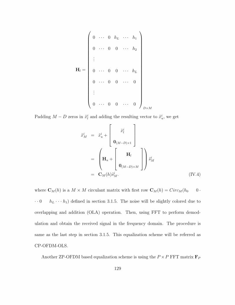
Hl =
0 · · · 0 hL · · · h1
0 · · · 0 0 · · · h2
...
0 · · · 0 0 · · · hL
0 · · · 0 0 · · · 0
...
0 · · · 0 0 · · · 0
D×M
Padding M −D zeros in xil and adding the resulting vector to xi
u, we get
xiM = xi
u +
xil
0(M−D)×1
=
Hu +
Hl
0(M−D)×M
si
M
= CM(h)siM . (IV.4)
where CM(h) is a M ×M circulant matrix with first row CM(h) = CircM(h0 0 ·
· · 0 hL · · · h1) defined in section 3.1.5. The noise will be slightly colored due to
overlapping and addition (OLA) operation. Then, using FFT to perform demod-
ulation and obtain the received signal in the frequency domain. The procedure is
same as the last step in section 3.1.5. This equalization scheme will be referred as
CP-OFDM-OLS.
Another ZP-OFDM based equalization scheme is using the P ×P FFT matrix FP
129

with entries exp−j2πmk/P/√
P to diagonalize the channel circulant matrix, which
is illustrated in the lower part of figure 4.8. Due to the D trailing zeros of ZP-OFDM,
the last D columns of H do not affect the received block. Thus, the Toeplitz matrix
H can be seen as a P × P circulant matrix CP (h) = CircP (h0, 0 · · · 0hL · h1). Then
we can rewrite equation IV.3 as
xizp = HFzps
iM + ni
P
= CP (h)Fzp + niP
Then we can do the diagonalization as follows:
FPHFzp = FPCP (h)Fzp
= FPCP (h)FHP FPFzp
= DP (hP )FPFzp
where hP = [H(0) · · ·H(2π/P ) · · ·H(2π(P − 1)/P )]T , DP (hP ) is the P × P diagonal
matrix with diagonal hP .
Because the channel H(z) is order of L, DP (hP ) can have at most L zero-diagonal
entries.However, unlike CP-OFDM, the remaining (at least P − L) nonzero entries
guarantee zero forcing recovery of siM in ZP-OFDM, regardless of the underlying
Lth-order FIR channel nulls [79]. The equalization scheme will be referred as ZP-
OFDM-FAST. We use this ZP-OFDM equalization scheme in our 64QAM TTCM
coded OFDM system performance evaluation [103] [71] [111].
130

4.3 Numerical Results
In order to improve the transmission data rate of the current HomePlug1.0 [104]
system, we select 16-state 64QAM TCM code as in chapter III to evaluate the OFDM
system performance. The channel is measured 60 feet powerline channel. The re-
sultant data rate is 39Mbps, which is 3 times of the current HomePlug1.0 system
(13Mbps). All simulation results are averaged over 500 packets with a payload of
1.7k bytes.
The BER performance of the system is illustrated in Figure 4.9. There are 6.7×10⁶
(500 packets × 40 OFDM symbols/packet × 84 QAM symbols/OFDM symbol × 4
bits/QAM symbol) random bits simulated to measure the BER. We obtain BER of
1.8× 10⁻⁵ at Eb/N0 = 9.7dB for 39Mbps coded OFDM system over power line. Fig-
ure 4.10 gives the PER performance for the same situation, reporting a low PER of
0.028 at Eb/N0 = 9.7dB.
131

4 6 8 10 12 14 16 1810
−6
10−5
10−4
10−3
10−2
10−1
Eb/N0 (dB)
BE
R
AWGN−coded−64QAMAWGN−uncoded−16QAMPWL−coded−64QAM:PWL−uncoded−16QAM
Figure 4.9: BER of OFDM/64QAM over power line and AWGN channel.
132

4 6 8 10 12 14 16 1810
−3
10−2
10−1
100
Eb/N0 (dB)
PE
R
AWGN−coded−64QAMAWGN−uncoded−16QAMPWL−coded−64QAM:PWL−uncoded−16QAM
Figure 4.10: PER of OFDM/64QAM over power line and AWGN channel.
133

CHAPTER V
TURBO TCM CODED OFDM
SYSTEM FOR IMPULSIVE
NOISE CHANNEL
In the real wireless communications systems besides AWGN there are impulsive
man-made noise from ignition of automobile or other sources such as power line which
affect the performance of the system. The impulsive noise is an additive disturbance
that arises primarily from the switching electric equipment. Therefore, bursty or iso-
lated errors are usually generated by an impulsive noise affecting consecutive symbols
in trellis based decoding algorithms, such as Viterbi and MAP algorithm, because
such decoder relies on the history of the symbol sequence [105]. For OFDM system,
134

the longer OFDM symbol duration provides an advantage in a presence of impulse
noise, because impulsive noise energy is spread out among simultaneously transmit-
ted OFDM sub-carriers. However, it has been recently recognized that this advantage
turns into a disadvantage if the impulsive noise energy exceeds certain threshold [106].
Further more, the statistical characteristics of the impulsive noise are much different
from those of Gaussian noise. Therefore, the performance of OFDM systems endur-
ing impulsive noise needs to be evaluated for shedding some light on building robust
decoding algorithm against impulsive noise.
We have studied the performance of conventional iterative bit MAP decoder which
is designed for gaussian noise in previous chapters. In this chapter, we will investi-
gate the effect of impulsive noise on the performance of the Turbo TCM coded OFDM
system. The conventional iterative bit MAP decoding algorithm is modified to catch
up the corresponding impulsive noise statistical characteristics. The bit error rate
(BER) performance of the TTCM coded OFDM systems over both AWGN channel
and UWB channel with impulsive noise is evaluated through simulation.
5.1 System and Channel Model
We are considering the OFDM system presented in figure 3.1, in which OFDM
data tones are coded through parity-concatenated TCM with 64QAM constellation
modulation. Trailing Zeros are appended after IFFT modulation, where the system
135

will be referred as ZP-OFDM. In each OFDM symbol interval symbols {Sk} are trans-
formed by means of IFFT and digital-to-analog conversion to the baseband OFDM
signal as
s(t) =N−1∑n=0
Ske(j2πk∆f t), t ∈ [0, TFFT ], (V.1)
where ∆f and N are again defined as the subcarrier frequency spacing and the num-
ber of total subcarriers used, respectively. TFFT is the OFDM symbol interval. After
the inverse FFT at the transmitter, cyclic prefix or zero-padding prefix is inserted to
avoid interblock interference (IBI).
The received signal (in time domain) after down-conversion, analog-to-digital con-
version, cyclic prefix removal, and synchronization can be represented as
rk =L∑
l=1
hlsk−l + wk + ik, k = 0, 1, . . . , N − 1, (V.2)
where sk = s(kTFFT /N), hl is the channel impulse response, L is the order of channel
impulse response, wk is the additive white Gaussian noise (AWGN) with zero mean
and ik is the impulse noise. For memoryless channels, hl = 1 for l = 1, . . . , L.
There have been many literature discussing the effect of impulsive noise [105]
[106] [107] [108] [109]. Here, we are considering a set of impulsive noise which can be
modelled, as in [109], as
p(nk; Ak) = p(nk; σ2k, η
Ck )
=ηC
k
2σ√
a(ηCk )Γ( 1
ηCk)e− |nk|
ηCk
[a(ηCk
)]ηCk
/2σ
ηCk
k
136

where the parameter Ak = (σ2k, η
Ck ), nk is the noise added on transmitted symbol, Γ(.)
denotes the Gama function, σ2k is the variance of the noise and a(ηC
k ) =Γ( 1
ηCk
)
Γ( 3
ηCk
). When
ηCk = 2, p(n) is the Gaussian distribution function. When ηC
k = 1, p(n) becomes the
Laplace distribution function. And when ηCk = 0.5, p(n) is the Sqrt noise mentioned
in [109].
When OFDM system is applied to UWB channel, the impulsive noise mentioned
above will cause severe degradation of the system performance.
5.2 Modified Iterative Bit MAP Decoder
We still apply the turbo iterative decoding scheme as in Chapter III and IV,
and make certain modifications to match the statistical characteristics of the channel
impulsive noise. The branch metric in the basic MAP algorithm is modified according
to the PDF of the impulsive noise [110]. The iterative decoding scheme is kept same
as before.
Under Gaussian noise environment, the channel transition probability is based
on Gaussian PDF and the Euclidian distance between the received signal and the
candidates of the transmitted signal, which can be described by V.3:
p =1
σ√
2πexp(−(ykI − xiI)
2 + (ykQ − xiQ)2
2δ2(V.3)
where I and Q represent in-phase and quadrature component of the kth sample in
received sequence yN1 . xi indicates the ith candidate of transmitted sequence xN
1 .
137

So the conventional MAP decoding is optimized for Gaussian noise by selecting the
symbol which has minimum Euclidean distance from transmitted one.
Above analysis tells that the noise PDF is also used to derive the branch metrics
for optimal trellis-based decoding algorithms like MAP. For channels with impulsive
noise, the channel noise can not be approximated through Gaussian PDF any more.
Therefore, the channel transition probability should be modified accordingly and take
into account the statistical distribution of the channel noise. The modified channel
probability is given in equation V.4:
p =ηD
k
2σk
√a(ηD
k )Γ( 1ηD
k)e− |nk|
ηDk
[a(ηDk
)]ηDk
/2σ
ηDk
k (V.4)
where nk =√
(ykI − xiI)2 + (ykQ − xiQ)2 denoting the Euclidean distance between
the received symbol and the candidate of transmitted symbol. Similarly, if ηDk = 2, the
channel probability p is a Gaussian distribution function. Then this MAP is exactly
same as the one optimized for Gaussian channel. If ηDk = 1, p is a Laplace distribution
function. And if ηDk = 0.5, p is the Sqrt noise mentioned in [109]. Obviously, the
optimal decoder requires that ηDk = ηC
k . Otherwise, due to channel variation or
estimation error, an additional ”mismatched error” will occur to increase the total
error probability.
5.3 Numerical Results
Simulations of the parity-concatenated TCM coded OFDM system with 64QAM
138
modulation through different channels with different channel impulsive noise were
carried out. 16-state TCM code with octal notation (23,35,33,37,31) is selected and
system level simulation were performed to measure the BER performance. The re-
sulted data rate is 1Gbps. The system is assumed to be perfectly synchronized. All
simulation results are averaged over 2000 packets with a payload of 2k bytes.
The BER performance of the coded 64QAM OFDM system over AWGN (η = 2.0)
channel and impulsive noise channels (η = 0.5, 1.0) is evaluated. There are 3.28×10⁷
random bits simulated to measure the BER. Figure 5.1 shows the effect of more im-
pulsivity of noise on the performance. When the η becomes large, the performance
tends to AWGN.
Figure. 5.2 illustrates the performance for coded 64QAM OFDM system over
UWB channel with Gaussian noise and impulsive noise of different η parmeters. The
figure indicates the same effect of impulsive noise on the system performance: the
smaller the η, the sharper the impulsive noise and the severer the performance degra-
dation. Again when η becomes large, the performance tends to that with AWGN
noise.
139

2.5 3 3.5 4 4.5 5 5.5 6 6.510
−6
10−5
10−4
10−3
10−2
10−1
Eb/N0 (dB)
BE
R
Eta=0505Eta=1010Eta=2020(AWGN)
Figure 5.1: BER of OFDM/64QAM over memoryless channel with different impulsive
noise.
140

3 4 5 6 7 8 9 10 11 1210
−5
10−4
10−3
10−2
10−1
Eb/N0 (dB)
BE
R
Eta(C/D)=0.5/0.5(Sqrt)Eta(C/D)=1.0/1.0(Laplace)Eta(C/D)=2.0/2.0(AWGN)
Figure 5.2: BER of OFDM/64QAM over UWB channel with different impulsive noise.
141
5.4 Summary
The BER performance of Turbo TCM coded OFDM system under AWGN noise
and impulsive noises were presented. The simulation results have shown that the
performance of OFDM system in the impulsive noise environment depends on the
impulsivity of the noise and the decoding algorithm has to take the noise impulsivity
into account for optimal decoding. Therefore, we modify the iterative bit MAP
algorithm used for Gaussian noise to match the impulsive channel noise statistical
characteristics.
142

CHAPTER VI
CONCLUSION
6.1 Summary of Results
A brief summary of accomplished work is given in this chapter with an emphasis
on the contributions to the subjects of Turbo TCM and OFDM systems.
In this thesis, we constructed a punctured parity-concatenated TCM encoder in
which a TCM code is used as the inner code and a simple parity-check code is used
as the outer code. It functions as a turbo TCM, which may gain a big advantage in
the real world implementation due to the savings of constituent encoder and inter-
leavers, and has potential for offering much higher spectral efficiency when used in
OFDM systems. The simple outer parity-check code can be easily extended to more
complicated parity-concatenated TCM for coding rate diversity.
Based on the iterative bit MAP decoder for standard binary turbo codes, corre-
143

sponding iterative decoding algorithm is extended for our parity-concatenated TCM
codes. We show several essential requirements to extract the extrinsic information
from each iteration, which is required to be independent and non-repeatable, and
provide to next iteration as a priori probability for branch metric computation in
MAP decoding process.
One of UWB proposals in the IEEE P802.15 WPAN project is to use a multi-band
orthogonal frequency-division multiplexing (OFDM) system and punctured convolu-
tional codes for UWB channels supporting data rate up to 480Mb/s. In this paper
we examine the possibility of improving the proposed system using Turbo TCM with
QAM constellation for higher data rate transmission. We applied our punctured
parity-concatenated trellis codes, in which a TCM code is used as the inner code and
a simple parity-check code is used as the outer code, to the current OFDM/UWB
system. The study shows that the system can offer much higher spectral efficiency,
for example, 1.2 Gbps, which is 2.5 times higher than the current proposed system.
We show several essential requirements to achieve high rate such as frequency and
time diversity, multi-level error protection.
Convergence analysis of iterative decoding algorithms is a very important tool to
predict code performance, its ability to provide insights into the encoder structure,
and its usefulness in helping with the code design. In this dissertation, we use Gaus-
sian approximation to track the density of extrinsic information in iterative turbo
decoders. We model the Gaussian density based on the empirically determined mean
144

and variance as independent parameters. The method is applied to both AWGN
channel and UWB channel for OFDM system and confirms the system performance
simulation result.
There are many different approaches to evaluate the performance of TCM codes
or turbo codes. Most of of the turbo type code performance evaluation is based on
conventional turbo structure and then finds the average performance bounds (aver-
aged over all possible interleavers). Since our encoder functions as a Turbo TCM
but due to the multiple input streams and punctured information bits, it’s hard to
use the evaluation method proposed previously. We try to explore the exhaustive
enumeration of TTCM codewords to confirm the code performance. Short block code
is evaluated using this method and the consistency between the evaluation and sim-
ulation results is obtained.
The same coding scheme can also be applied to the OFDM system for HomePlug
powerline channels since OFDM is selected as the modulation scheme in HomePlug
standards. Similar simulations are done to OFDM/Powerline system and obtain bet-
ter bit error rate (BER) and packet error rate (PER) performance. The work has
shown that we can deliver data rate of 39Mbps comparing to 13Mbps data rate of
current HomePlug1.0 systems.
Another big issue in the real wireless communications systems is the fact that there
are impulsive man-made noise from ignition of automobile or other sources such as
power line which affect the performance of the system besides AWGN noise. We
145

investigate the effect of impulsive noise on the performance of the Turbo TCM coded
OFDM system and come up with a modified iterative bit MAP decoding algorithm
to catch up the corresponding impulsive noise statistical characteristics. The bit er-
ror rate (BER) performance of the TTCM coded OFDM systems over both AWGN
channel and UWB channel with impulsive noise is evaluated through simulation. Our
work has shown that the optimal decoder requires a matched probability distribution
function to the channel pdf of the additive impulsive noise. Otherwise, due to channel
variation or estimation error, an additional ”mismatched error” will occur to increase
the total error probability.
6.2 Further Research
The future research can be extended on following areas:
(1) The parity-concatenated TCM encoder structure described in this dissertation
can be further constructed into more complicated coding schemes. Since currently
the encoder is built as a concatenation of a simplest parity-check outer code and
TCM inner code. More complicated outer codes can be constructed to provide
strong error correction ability and higher spectral efficiency;
(2) The iterative bit MAP decoding algorithm can be further optimized for better
performance, such as enabling more iteration and avoiding overflow problem;
146

(3) Based on the results from this dissertation, larger QAM constellation size, such as
256-pint or 1024-point, and multidimentional TCM structure can be explored for
even higher data rate transmission through OFDM/UWB and OFDM/HomePlug
systems.
(4) Based on the analysis of the effect of impulsive noise on OFDM system in this
dissertation, more evaluations of mixed noise conditions can be conducted in the
future. Powerful coding scheme for OFDM system and corresponding robust
decoding algorithms for un-predicted impulsive noise type in the channel are
very necessary in today’s real communication system in which higher spectral
efficiency with higher data rate transmission is highly desired [112].
147

LIST OF REFERENCES
[1] C. E. Shannon, “A Methematical Theory of Communications,” Bell Syst. Tech.
J., Vol. 27, pp.379-423 (Part I), 623-656(Part II), Jul. 1948.
[2] C. Berrou, A. Glavieux and P. Thitimajshima, “Near Shannon Limit Error Cor-
recting Coding and Decoding: Turbo Codes,” Proc. ICC-93, pp.1064-1070,
Geneva, Switzerland, 1993.
[3] R. G. Gallager, “Low-density parity-check codes,” IRE Trans Inform. Theory,
vol IT-8 pp. 21-28, Jan 1962.
[4] D.J.C. MacKay, “Good Codes based on Very Sparse Matrices,” IEEE Trans.
Inform. Theory, Vol. 45, pp.399-431, March, 1999.
[5] S. Benedetto and G. Montorsi, “Serial Concatenation of Block and Convolutional
Codes,” Electronics Letters, Vol. 32, pp.887-888, 1996.
[6] S. Benedetto and G. Montorsi, “Design of Parallel Concatenated Convolutional
Codes,” Electronics Letters, Vol. 32, pp.887-888, 1996.
148

[7] S. Benedetto and G. Montorsi, “Unveiling Turbo-codes: Some Results on Paral-
lel Concatenated Coding Schemes,” IEEE Trans. Inform. Theory, Vol. 42, no.
2,pp.409-428, Mar. 1996.
[8] J. Hagenauer, E. Offer, and L. Papke, “Iterative Decoding of Binary Block and
Convolutional Codes,” IEEE Trans. Inform. Theory, Vol. 42, pp.429-445, Mar.
1996.
[9] P. Robertson and T. Woerz, “A Novel Bandwidth-efficient Coding Scheme Em-
ploying Turbo-Codes,” Proc. IEEE Int. Conf. Comm., ICC’96, pp 962-967.
[10] P. Robertson and T. Worz, “Bandwidth-efficient turbo trellis-coded modulation
using punctured component codes,” IEEE J. on select. Areas in Commun., Vol.
16, No. 2, pp 206 - 218, Feb. 1998.
[11] P. Robertson and T. Worz, “Extensions of Turbo Trellis-coded Modulation to
High Bandwidth Efficiency,” IEEE Int. Conf. on Commun. (ICC’ 97), Vol. 3,
No. 2, pp 1251-1255, Jun. 1997.
[12] S.LeGoff, A. Glavieux, and C. Berrou, “Turbo Codes and High Spectral Effi-
ciency Modulation,” Proceedings of IEEE ICC’94, May 1-5, 1994, New Orleans,
LA.
[13] S. Benedetto, D. Divsalar, G. Montorsi, and F. Pollara, “Parallel Concatenated
Trellis-coded Modulation,” Proceeding of IEEE ICC’96, pp.974-978, 1996.
149

[14] C. Fragouli and D. Wesel, “Turbo-Encoder Design for Symbol-Interleaved Par-
allel Concatenated Trellis-Coded Modulation,” IEEE Trans. on Commun., Vol.
49, No. 3, pp.425-435, Mar. 2001.
[15] G. D. Forney, M. D. Trott,and S.-Y. Chung “Approaching AWGN channel ca-
pacity with coset codes and multilevel coset codes,” IEEE Trans. Inform. Theory,
Vol. 46, pp.820-850, May 2000.
[16] G. D. Forney,Jr. and L. F. Wei, “Multidimensional Constellation -Part I: Intro-
duction, figure os merit, and generalized cross constellation,” IEEE J. on select.
Areas in Commun., Vol. 7, pp.877-892, Aug. 1989.
[17] L. U. Wachsmann and J. Huber, “Power and Bandwidth Efficient Digital Com-
munications Using Turbo Codes in Multilevel Codes,” Eur. Trans. on Telecomm,
vol. 6, no. 5, pp. 557-567, Sept./Oct., 1995.
[18] Q. Wang, L.Wei and R.A. Kennedy, “Iterative Viterbi Decoding, Trellis Shap-
ing, and Multilevel Structure for High-rate Parity-check TCM,” IEEE Trans. on
Comm., Vol. 50, No. 1, pp.48-55, Jan. 2002.
[19] Q. Wang, “Near Optimal Decoding for Trellis-coded Modulaiton,” PhD Diser-
tation, Australian National University, Canberra, Australia, 2000.
150

[20] Q. Wang and L.Wei, “Graphic-Based Iterative Decoding Algorithms for Parity-
Concatenated Trellic Codes,” IEEE Trans. Infor. Theory, Vol. 47, No. 3, pp.1062-
1074, Mar. 2001.
[21] M.Z. Win, R. A. Scholtz, “Impulse Radio: How It Works,” IEEE Commun.
Lett., Vol. 2, No. 2, pp. 36-38, Feb. 1998.
[22] M. Z. Win, R. A. Scholtz, “Characterization of Ultra-Wide Bandwidth Wireless
Indoor Channels: A Communication-Theoretic View,” IEEE Journal on Sel.
Areas in Commun., Vol. 20, No. 9, pp. 1613-1627, Dec. 2002.
[23] M. Z. Win, R. A. Scholtz, “Ultra-Wide Bandwidth Time-hopping Spread-
Spectrum Impulse Radio for Wireless Multiple-Access Communications,” IEEE
Trans. on Commun., Vol. 48, No. 4, pp. 679-691, Apr. 2000.
[24] J. D. Choi and W. E. Stark, “Performance of Ultra-wideband Communications
with Suboptimal Receivers in Multipath Channels,” IEEE Journal on Sel. Areas
in Commun., Vol. 20, No. 9, pp. 1754-1766, Dec. 2002
[25] W. Turin, R. Jana and V. Tarokh, “Autoregressive Modeling of An Indoor UWB
Channel ,” IEEE Conf. Ultra Wideband Sys. and Tech., 2002.
[26] M. Z. Win, G. Chrisikos, and N. R. Sollenberger, “Performance of Rake Re-
ception in Dense Multipath Channels: Implications of Spreading Bandwidth and
151
Selection Diversity Order,” IEEE Journal on Sel. Areas in Commun., Vol. 18,
No. 8, pp.1516-1525, Aug. 2000
[27] S.-Y. Wang and C.-C. Huang, “On the Architecture and Performance of an FFT-
based Spread-spectrum Downlink RAKE Receiver,” IEEE Trans. on Vehicular
Tech., Vol. 50, No. 1, pp. 234-243, Jan. 2001
[28] D. Cassioli, M. Z. Win, F. Vatalaro, and A. F. Molisch, “Performance of Low-
complexity RAKE Reception in a Realistic UWB Channel,” IEEE Int. Conference
on Commun. (ICC 2002), Vol. 2, No. 28, pp.763-767, Apr. 2002
[29] A. Rajeswaran, V. S. Somayazulu, and J. R. Foerster, “RAKE Performance for
a Pulse Based UWB System in a Realistic UWB Indoor Channel,” IEEE Int.
Conference on Commun. (ICC 2003), Vol. 4, pp.2879-2883, May 2003.
[30] A. Rajeswaran, V. S. Somayazulu, and J. R. Foerster, “Optimal and Subopti-
mal Receivers for Ultra-wideband Transmitted Reference Systems,” IEEE Global
Telcomm. Conf. (GLOBECOM ’03), Vol. 2, pp.759-763, Dec. 2003.
[31] L. Cimini, Jr., “Analysis and Simulation of a Digital Mobile Channel Using
Orthogonal Frequency Division Multiplexing,” IEEE Trans. on Commun., Vol.
33, No. 7, pp. 665-675, Jul. 1985.
152

[32] J. Kim, L. J. Cimini,Jr., and J. C. Chuang, “Coding Strategies for OFDM with
Antenna Diversity High-bit-rate Mobile Data Applications,” 48th IEEE conf. on
Vehicular Tech. (VTC 98), Vol. 2, pp. 763-767, May 1998.
[33] L. Lin, L. J. Cimini,Jr, and J. C.-I. Chuang, “Turbo Codes for OFDM with
Antenna Diversity,” 49th IEEE conf. on Vehicular Tech. (VTC 99), Vol. 2, pp.
1664-1668, May 1999.
[34] W. Y. Zou, and Y. Wu, “COFDM: An Overview,” IEEE Trans. on Broadcasting,
Vol. 41, No. 1, pp.1-8, Mar. 1995.
[35] K.-B. Png, X. Peng, and F. Chin, “Performance Studies of a Multi-band OFDM
System Using a Simplified LDPC Code,” Joint UWBST & IWUWBS. 2004,
pp.376-380, May 2004.
[36] B. Saltzberg, “Performance of an Efficient Parallel Data Transmission System,”
IEEE Trans. on Commun., Vol. 15, No. 6, pp.805-811, Dec. 1967.
[37] R. W. Chang, “High-speed Multichannel Data Transmission with Bandlimited
Orthogonal Signals,” Bell System Technical Journal, Vol. 55, pp.1175-1796, Dec.
1966.
[38] S. C. Cho, J. U. Kim, K. T. Lee and K. R. Cho; “Convolutional Turbo Coded
OFDM/TDD Mobile Communication System for High Speed Multimedia Ser-
vices,” Proc. Telecommun. - Adv. Industr. Conf. Telecommun./Serv. Assur. Part.
153

Int. Res. Conf./E-Learn. Tel. (Workshop AICT/SAPIR/ELETE 2005), pp.244-
248, Jul. 2005.
[39] A. Batra, et al., “Multi-band OFDM Physical Layer Proposal for IEEE P802.15
Task Group 3a,” IEEE P802.15-03/268r2, Nov. 2003.
[40] G. Ungerboeck, “Channel Coding with Multilevel/phase Signals,” IEEE Trans.
Inform. Theory, Vol. IT-28, pp.55-67, 1982.
[41] G. Ungerboeck, “Trellis-coded Modulation with Redundant Signal Sets-Part I:
Introduction,” IEEE Communications Magazine, Vol. 25, no. 2, Feb. 1987.
[42] G. Ungerboeck, “Trellis-coded Modulation with Redundant Signal Sets-Part 2:
State of the Art,” IEEE Communications Magazine, Vol. 25, no. 2, Feb. 1987.
[43] L. F. Wei, “Rotatoinally Invariant Convolutionlsl Channel Coding with Ex-
panded Signal Space - Part I: 180 Degrees and Part II: Nonlinear Codes,” IEEE
J. Sel. Areas in Commun., Vol. SAC-2, pp.659-686, Sep. 1984.
[44] L. F. Wei, “Trellic-coded Modulation with Multidimensional constellations,”
IEEE Trans. Inform. Theory, Vol. IT-33, pp.483-501, Jul. 1987.
[45] L. F. Wei, “Rotatoinally Invariant Trellic-coded Modulation with Multidimen-
sional M-PSK,” IEEE J. Sel. Areas in Commun., Vol. 7, No. 9, pp.1281-1295,
Dec. 1989.
154

[46] G. D. Forney, Jr., “Concatenated Codes,” MIT Press, Cambridge, Mass, 1963.
[47] G. Ungerboeck, “On Improving Data-link Performance by Oncreasing Chan-
nel Alphabet and Introducing Sequence Decoding,” Int. Sym. Inform. Theory,
Ronneby, Sweden, June 1976
[48] A. J. Viterbi, “Error bounds for convolutional codes and an asymptotically
optimum decoding algorithm,” IEEE Trans. Inform. Theory, Vol. 13, pp.260-
269, Apr. 1967.
[49] A.K. Khandani and P. Kabal, “Shaping Multidimensional Signal Spaces –Part
I: Optimum Shaping, Shell Shaping and Part II: Shell-addressed Constellations,”
IEEE Trans. Inform. Theory, Vol. 39, pp.1799-1819, Nov. 1993.
[50] G. D. Forney, Jr. and G, Undergoeck, “Modulation and Coding for Linear
Gaussian channels,” IEEE Trans. Inform Theory, Vol. IT-44, No. 6, pp.2389-
2415, Oct. 1998.
[51] M. Eyuboglu G. D. Forney, P. Dong and G. Long, “Advanced Modulation Tech-
niques for V. Fast,” Eur. Trans. on Telecom, pp.243-256, May. 1993.
[52] D. Davsalar and R. J. McEliece, “Effective Free Distance of Turbo-codes,” Elec-
tronis Letters, Vol. 32, no. 5, pp.445-446, Feb. 1996.
155

[53] S. Benedetto, D. Divsalar, G. Montorsi, and F. Pollara, “Serial Concatenation of
Interleaved Codes: Performance Analysis, Design, and Iterative Decoding,” IEEE
Trans. Inform. Theory, Vol. 44, no. 3, pp.909-926, May. 1998.
[54] L. C. Perex, J. Seghers, and D. J. Costello, Jr., “A Distance Spectrum Interpre-
tation of Turbo Codes,” IEEE Trans. Inform. Theory, Vol. IT-42, pp.1698-1709,
Nov. 1996.
[55] R. J. McEliece, D. J. MacKay, and J. F. Cheng, “Turbo Coding as an Instance
of Pearl’s ”Belief Propagation” Algorithm,” IEEE Journal on Selected Areas in
Comm., Vol. 16, no. 2, pp.140-152, Feb. 1998.
[56] A. S. Barbulescu and S. S. Pietrobon, “Interleaver Design for three Dimensional
Turbo-codes,” Proc. 1995 IEEE International Symposium on Information Theory,
Whistler, British Columbia, Canada, p. 37, Sept. 1995.
[57] R. Pyndiah, A. Glavieux, A. Picart, and S. Jacq, “Near Optimum Decoding of
Product Codes,” Proc. of GLOBALCOM’94, San Francisco, CA, Vol. 1, pp.339-
343, Nov. 1994.
[58] J. Hagenauer, and P. Hoeher, “A Viterbi Algorithm with Soft-decision Outputs
and its Applications,” Proc. Globalcom’89, Dallas, TX, pp.47.1.1-7, Nov. 1989.
[59] D. Divsalar and F. Pollara, “On the Design of Turbo Codes,” JPL TDA Progress
Report 42-123, Nov. 15, 1995
156

[60] C. Berrou, A. Glavieux, “Near Optimum Error Correcting Coding and Decoding:
Turbo Codes,” IEEE Trans. on Comm., vol. 44, no. 10, pp. 1261-1271, Oct. 1996.
[61] L.R. Bahl, J. Cocke, F. Jelinek, and J. Raviv, “Optimal Decoding of Linear
Codes for Minimizing symbol Error,” IEEE Trans. Inform. Theory, pp.284-287,
Mar. 1974
[62] L. U. Wachsmann, Robert F. H. Fischer, and J. B. Huber, “Multilevel Codes:
Theoretical Concepts and Practical Design Rules ,” IEEE Trans. on Info. Theory,
vol. IT-45, no. 5, pp. 1361-1391, July 1999.
[63] H. Imai and S. Hirakawa, “A New Multilevel Coding Method Using Error-
correcting Codes,” IEEE Trans. Inform. Theory, Vol. IT-23, No. 3, pp.371-377,
May. 1977.
[64] J. Hagenauer, P. Robertson, and L. Papke, “Iterative (’Turbo’) Decoding of
Systematic Convolutional Codes with the MAP and SOVA algorithm,” Proc. of
1994 ITG Conference on Source and Channel Coding, Munich, pp.1-9, Oct. 1994.
[65] A. J. Goldsmith, “Wireless Communcations,” Cambridge University Press, Sep.
2005.
[66] B. Le Floch, M. Alard, and C. Berrou, “Coded Orthogonal Frequency Division
Multiplex,” Proceedings of the IEEE, Vol. 83, No. 6, pp. 982-996, Jun. 1995.
157

[67] W. A. C. Fernando, R.M.A.P. Rajatheva, and K.M. Ahmed, “Performance of
coded OFDM with higher modulation schemes,” Proc. Int. Conf. Commun. Tech.
(ICCT ’98), Vol. 2, Oct. 1998.
[68] A. Scaglione, G.B. Giannakis, and S. Barbarossa, “Redundant Filterband Pre-
coders and Equalizers–Part I: Unification and Optimal Designs and Part II: Blind
Channel Estimation, Synchronization, and Direct Equalization,” IEEE Trans. on
Signal Processing, Vol. 47, No. 7, pp. 1988-2022, Jul. 1999.
[69] A. Batra, J. Balakrishnan, G. R. Aiello, J. R. Foerster, and A. Dabak, “Design
of a Multiband OFDM System for Realistic UWB Channel Environments,” IEEE
Trans. Microwave Theory and Tech., Vol. 52, No. 9, pp. 2123-2138, Sep. 2004.
[70] Y. Wang, L. Yang, and L. Wei, “High speed turbo TCM coded OFDM system
for UWB channels,” Proc. Int. Symp. Info. Theory. (ISIT2005) pp. 1150-1150,
Sept. 2005.
[71] Y. Wang, L. Yang, and L. Wei, “High Speed Turbo Coded OFDM UWB System,”
accepted by EURASIP Journal on Wireless Commun. and Networking breakup
special issue on Ultra-Wideband (UWB) Commun. Sys. Tech. and App.
[72] D. Divsalar, H. Jin, and R. J. McEliece, “Coding theorems for ‘turbo-like’ codes,”
in Proc. 1998 Allerton Conf. Communication, Control and Computers, Allerton,
IL, Sept. 1998, pp.201-210.
158

[73] Z. Irahhauten, H. Nikookar, and Gerard J. M. Janssen, “An Overview of Ultra
Wide Band Indoor Channel Measurements and Modeling ,” IEEE Micro. and
Wire. Comp. Lett., Vol. 14, NO. 8, Aug. 2004.
[74] A. Saleh, R. Valenzuela, “A Statistical Model for Indoor Multipath Propaga-
tion,” IEEE Journal on Sel. Areas in Commun., Vol. 5, No. 2, pp. 128-137, Feb.
1987.
[75] H. Hashemi, “The Indoor Radio Propagation Channel,” proc. IEEE, Vol. 81,
pp. 943-968, Jul. 1993.
[76] H. Hashemi, “Impulse Response Modeling of Indoor Multipath Propagation,”
IEEE J. Select. Areas Commun., Vol. 11, pp. 967-978, Sep. 1993.
[77] R. J.-M. Cramer, R. A. Scholtz, and M. Z. Win, “Evaluation of an ultra-wide-
band propagation channel Cramer,” IEEE Trans. on Anten. and Prop8, Vol., No.
5, pp. 561 - 570, May 2002.
[78] J. Foerster, Ed., “Channel Modeling Sub-committee Report Final,” IEEE802.15-
02/490.
[79] B. Muquet, Z. Wang, G. B. Giannakis, M. de Courville, and P. Duhamel, “Cyclic
Prefix or Zero Padding for Wireless Multicarrier Transmission?,” IEEE Trans. on
Commun., Vol. 50, No. 12, pp. 2136-2148, Dec. 2002.
159

[80] Z. Wang, and G. B. Giannakis, “Wireless Multicarrier Communications: Where
Fourier Meets Shannon,” IEEE Signal Processing Mag., pp. 29-48, May 2002.
[81] P. D. Papadimitriou and C. N. Georghiades, “Zero-padded OFDM with improved
performance over multipath channels,” IEEE Consumer Communications and
Networking Conference (CCNC 2004), pp. 31-34, Jan. 2004.
[82] S. Benedetto, D. Divsalar, G. Montorsi, and F. Pollara, “Serial Concatenated
Trellis-coded Modulation with Iterative Decoding,” Proceeding of IEEE ISIT’97,
pp.8, Ulm, Germany, June 29 - July 4, 1997.
[83] S. Benedetto, D. Divsalar, G. Montorsi, and F. Pollara, “Soft-output Decod-
ing Algorithms for Continuous Decoding of Parallel Concatenated Convolutional
Codes,” IEEE Int. Conf. on Commun. (ICC’ 96), Vol. 1, pp. 112-117, Jun. 1996
[84] S. T. Brink, “Convergence Behavior of Iterative Decoded Parallel Concatenated
Codes,” IEEE Trans. on Commun., Vol. 49, pp. 1727-1737, Oct. 2001.
[85] H. E. Gamal, and A. R. Hammons, “Analyzing the turbo decoder using Gaussian
Approximation,” IEEE Trans. Inform. Theory, Vol. 47, pp. 671-686, Feb 2001.
[86] D. Divsalar, S. Dolinar, and F. Pollara, “Iterative turbo decoder analysis based
on density evolution,” IEEE Journal on Sel. Areas in Commun., Vol. 19, No. 5,
pp. 891-907, May 2001.
160
[87] Divsalar, D., Dolinar, S., Pollara, F., “Serial turbo trellis coded modulation with
rate-1 inner code,” Proceeding of IEEE ISIT, pp. 194, 25-30 Jun. 2000
[88] A. J. Viterbi, “Convolutional Codes and Their Performance in Communications
System,” IEEE Trans. on Commun. Tech., Vol. COM-19, No. 5, pp. 751-772,
Oct. 1971.
[89] G. D. Forney, Jr., “Lower Bounds on Error Probability in the Presence of arge
Intersymbol Interference,” IEEE Trans. on Commun., Vol. 20, No. 1, pp. 76 - 77,
Feb. 1972.
[90] G. D. Forney, Jr., “Maximum-Likelihood Sequence Estimation of Digital Se-
quences in the Presence of Large Intersymbol Interfenrence,” IEEE Trans. on
Info. Theory, Vol. IT-18, No. 3, pp. 363-378, May. 1972.
[91] S. Benedetto and G. Montorsi, “Average Performance of Parallel Concatenated
Block Codes,” Electronic Letters, Vol. 31, No. 3, pp. 156-158, Feb. 1995.
[92] E. Zehavi, J. K. Wolf, “On the Performance Evaluation of Trellis Codes,” IEEE
Trans. Inf. Theory, Vol. IT-33, NO. 2, pp. 196-202, Mar. 1987.
[93] T. M. Duman, M. Salehi, “Performance Bounds for Turbo-coded Modulation
ystems,” IEEE Trans. on Commun., Vol. 47, No. 4, pp. 511-521, Apr. 1999.
161
[94] M. Rouanne, D. J. Costello, “An Algorithm for Computing the Distance Spec-
trum of trellis codes,” IEEE Journal on Sel. Areas in Commun., Vol. 7, No. 6,
pp. 929-940, Aug. 1989.
[95] S. Benedetto, M. Mondin, G. Montorsi, “Performance Evaluation of Trellis-coded
Modulation chemes,” Proceedings of the IEEE, Vol. 82, No. 6, pp. 833-855, Jun.
1994.
[96] J. G. Proakis, Digital Communications,, the third edition, McGr.aw-Hill, New
York, 1995.
[97] D. Divsalar, S. Dolinar, and F. Pollara, “Transfer Function Bounds on the
Performance of Turbo Codes,” TDA Progress Report 42-122, pp. 44-55, Aug.
1995.
[98] S. Benedetto, G. Montorsi, “A New Decoding Algorithm for Geometrically Uni-
form Trellis Codes,” IEEE Trans. on Commun., Vol. 44, No. 5, pp. 581-590, May.
1996.
[99] M. M. Salah, R. A. Raines, M. A. Temple, and T. G. Bailey, “Approach for
Deriving Performance Bounds of Punctured Turbo Codes,” Electronic Letters.,
Vol. 35, No. 25, pp. 2191-2192, Dec. 1999.
[100] R. Garello, P. Pierleoni, S. Benedetto, “Computing the Free Distance of Turbo
Codes and Serially Concatenated Codes with Interleavers: Algorithms and Appli-
162

cations,” IEEE Journal on Sel. Areas in Commun., Vol. 19, No. 5, pp. 800-812,
May 2001.
[101] L.C. Canencia, C. Douillard, M. Jezequel, and C. Berrou, “Application of
Error Impulse Method to 16-QAM Bit-Interleaved Turbo Coded Modulations,”
Electronics Letters, Vol. 39, No. 6, pp. 538-539, Mar. 2003.
[102] K. Wu, L. Ping, X. Huang, N. Phamdo, “Performance Analysis of Turbo-SPC
Codes,” IEEE Trans. on Info. Theory, Vol. 50, No. 10, pp. 2490-2496, Oct. 2004.
[103] Y. Wang, L. Yang, and L. Wei, “Turbo TCM Coded OFDM System For Power-
line Channel,” submitted to Turbo-coding 2006, Apr. 3-7, 2006, Munich, Germany.
[104] HomePlug 1.0.1 Specification, Dec. 2001.
[105] F. Abdelkefi, P. Duhamel, and F. Alberge, “Impulsive Noise Cancellation in
Multicarrier Transmission,” IEEE Trans. on Commun., Vol. 53, No. 1, pp. 94-106,
Jan. 2005.
[106] S. V. Zhidkov, “Impulsive Noise Suppression in OFDM Based Communication
Systems,” IEEE Trans. on Consumer Electronics., Vol. 49, NO. 4, Nov 2003, pp.
944-948.
[107] S. Kosmopoulos, P. T. Mathiopoulos, and M. D. Gouta, “Fourier-Bassel Error
Performance Analysis and Evaluation of M-ary QAM Schemes in an Impulsive
163

Noise Environment,” IEEE Trans. on Commun., Vol. 39, No. 3, pp. 398-404,
Mar. 1991.
[108] M. W. Thompson, D. R. Halverson, and G. L. Wise, “Robust Detection in
Norminally Laplace Noise,” IEEE Trans. on Commun., Vol. 42, No. 2/3/4, pp.
1651-1660, Feb/Mar/Apr. 1994.
[109] L. Wei, Z. Li, M. James, and I. R. Petersen, “A Minimax Robust Decoding
Algorithm,” IEEE Trans. on Inf. Th., Vol. 46, NO. 3, pp.1158-1167, May 2000.
[110] Y. Wang, and L. Wei, “Turbo TCM Coded OFDM Systems for Non-Gaussian
Channels,” submitted to 2006 IEEE International Symposium on Information
Theory (ISIT 2006) Jul. 9-14, 2006, Seattle, USA.
[111] Y. Wang, and L. Wei, “High Speed Turbo TCM OFDM Powerline System,”
prepared for submission.
[112] L. Yang, Y. Wang, and L. Wei, “Turbo TCM Coded OFDM Systems for
Impulsive Noise Channel,” prepared for submission.
164
Related Documents