Version 3 186 Part 4 High-Resolution Transmission Electron Microscopy

Welcome message from author
This document is posted to help you gain knowledge. Please leave a comment to let me know what you think about it! Share it to your friends and learn new things together.
Transcript

Version 3
186
Part 4
High-Resolution
Transmission
Electron Microscopy

Version 3
187
Significance
• high-resolution transmission electron microscopy (HRTEM):
resolve object details smaller than 1nm (10−9 m)
• image the interior of the specimen
– compare, e. g., scanning tunneling microscopy: atomic resolution, however only at the surface
• local
– compare, e. g., X-ray diffraction: averaging, “statistical” information
• direct imaging
– HRTEM images can be »intuitively« interpretable (however, severe restrictions apply – see below)
• direct imaging of atom arrangements (in projection)
– crystals (and quasi-crystals )
– in particular: structural defects · interfaces (grain boundaries, interphase interfaces) · stacking faults, anti-phase boundaries, inversion domain boundaries, … · crystals dislocations, disclinations, misfit dislocations, …
– however: projection ⇒ no (individual) point defects ⇒ defects need to be parallel to the viewing direction

Version 3
188
• techniques
– HRTEM (high-resolution transmission electron microscopy) · since 1980ies · »steady« improvement of conventional TEM · widespread application · focus of interest in this course
– holography · high-resolution electron holography is relatively new · record amplitude and phase (not just intensity) of the electron wave in
the image plane
– HAADF (high-angle angular dark-field) imaging (“z-contrast”) · new method · scanning transmission electron microscopy · requires annular (HAADF) detector
HRTEM versus CTEM (conventional TEM)
• contrast formation in CTEM
– sometimes absorption contrast, mostly diffraction contrast: · crystallites (grains) of different structure (different phases) or orientation · distortions induced by particles, dislocations, … · variation of the scattering amplitude by stacking faults, grain boundaries,
…
• CTEM bright-field imaging

Version 3
189
• CTEM dark-field imaging

Version 3
190
• example: Co precipitates in CuCo
– bright-field image
– distortion field introduced by the particles (plane bending) changes diffrac-tion conditions in the matrix ⇒»coffee bean« contrast
• principle of CTEM:
– different specimen regions generate Bragg reflections of different intensity
– contrast: either Bragg reflections or transmitted beam do not contribute to the image
⇒ consequence: interatomic spacings cannot be resolved

Version 3
191
Abbe Theory of Resolution
• ideal object (↔ crystal): lattice with period d
• coherent illumination: plane waves, wavelength λ
d
z=2
z=1
• diffraction:
– path difference between waves emitted from neighboring slits must equal an integer number of wavelengths, z · λ
– diffracted beams make angles ϕz, with the plane of the lattice, and
Sin !z[ ] =
z" #
d
• Abbe: only the diffracted beams carry information about the spacing d
⇒ to image the lattice, the optical system must at least include one diffracted beam (z = 1)

Version 3
192
⇒ generalization: to resolve an object under coherent illumination, the image formation must include at least the first diffraction maximum of the object
⇒ the aperture semi-angle α introduces a limit for the spatial resolution:
! Sin "1[ ] =
#
d < Sin $[ ]
⇒ resolution limit δ: smallest distance d that can be resolved
Sin[!1]= Sin["] # $ =
%
Sin "[ ]
⇒ resolving interatomic distances requires larger aperture than CTEM imaging and interference of (at least two) different Bragg reflections

Version 3
193
⇒ transition from CTEM to HRTEM:
– instrumental pre-requisites for interference images · illumination with a high degree of coherence
(small source, small spread of the wavelength) · mechanics and electronics sufficiently stable · electron lenses with small aberrations
(spherical and chromatic aberration, astigmatism)
– remove objective aperture
– ultra-thin specimen to avoid absorption and inelastic electron scattering (de-stroys coherence)
– orient the specimen to generate suitable Bragg reflections
• “ideal” HRTEM imaging (neglecting lens aberrations)
⇒ high resolution, but no contrast!

Version 3
194
Phase Contrast
• consider thin specimen, plane electron wave ψ0, no absorption
⇒ specimen just introduces small, locally varying phase shift (refractive index ↔ electrostatic potential)
• express exit wave ψe[ x ] as sum of incident wave ψ0 and scattered wave ψs[ x ]

Version 3
195
• phase of ψs[ x ] is shifted by −90° versus ψ0 :
! e x[ ] =!0 " i! s x[ ]
⇒ intensity:
! i x[ ]
2= !e x[ ]
2" ! 0 x[ ]
2
⇒ no contrast!
• must convert locally different phase shifts to locally different intensities (contrast ⇔ intensity variation)
→ if the optics introduces an additional phase shift of the scattered wave by −90°,
! i x[ ]
2= !0 x[ ] "!s x[ ]
2< ! 0 x[ ]
2
• problems:
– � � � � −90° phase shift cannot be realized in an ideal manner
– for TEM there exists no “λ/4 plate” as for light-optical microscopy
– in HRTEM, the required phase shift is introduced by · the spherical aberration of the objective lens · defocusing of the objective lens
– the image, which is obtained by interference of coherent electron waves, of-ten has a complex relationship with ψe, the electron wave function at the exit surface of the specimen
• consequence:
Correct interpretation of HRTEM images requires a quantitative un-derstanding of image formation.

Version 3
196
• example: Al/MgAl2O4 interface
– HRTEM in <110> projection
– microscope: JEM-ARM 1250 (Stuttgart)
• where are which atoms?!
– Al, Mg, O atom columns: “white” or “black”?
– relative visibility of the ions in the spinel?
Version 3
197
Electron Optics
• HRTEM:
– interference → wave properties
→ “wave model” of electron mandatory
• exact treatment of electron interference: quantum mechanics
• however: simpler wave optics also yields correct results – apart from image ro-tation and adjustments of the wave length λ
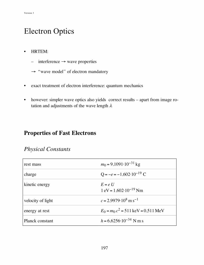
Properties of Fast Electrons
Physical Constants
rest mass m0 = 9,1091·10−31 kg
charge Q = −e = −1,602·10−19 C
kinetic energy E = e U 1 eV = 1,602·10−19 Nm
velocity of light c = 2,9979·108 m s−1
energy at rest E0 = m0 c2 = 511 keV = 0,511 MeV
Planck constant h = 6,6256·10−34 N m s

Version 3
198
Electrons in Motion
property non-relativistic relativistic
Newton’s law F =
d p
dt= m0
d v
dt
F =
d p
dt=
d
dtmv( )
mass m= m0
m=m0
1! v2/ c
2
energy E = eU = 1
2mv
2 mc2= E0 +E = m0c
2+ eU
velocity
v =2e
m0
v = c 1!1
1+ E/ E0( )2
momentum p = m0v= 2m0E p = mv=
1
c2EE0 + E2
de Broglie wavelength
! =h
p=
h
2m0E
! =hc
2EE0 + E2( )
• de Broglie wavelength as a function of the accelerating voltage:
200 400 600 800 1000 1200
0,5
1,0
1,5
2,0
2,5
3,0
! [pm]
U [kV]
classical
relativistic

Version 3
199
• velocity as a function of the accelerating voltage:
200 400 600 800 10001200
0,2
0,4
0,6
0,8
1,0 velocity of lightv/c
U [kV]
• kinetic and potential energy of the electrons on their way through the micro-scope
.
kin
etic
energ
y
cameracathode anode specimen
pote
nti
al energ
y
– specimen: · electrostatic potential varies ⇒ diffraction · free surfaces → average positive → “inner potential” Ui, attractive for electrons → acceleration, increase of the average velocity → wave length λ becomes smaller
Version 3
200
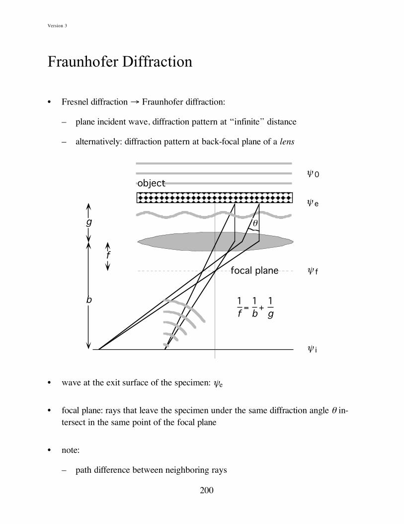
Fraunhofer Diffraction
• Fresnel diffraction → Fraunhofer diffraction:
– plane incident wave, diffraction pattern at “infinite” distance
– alternatively: diffraction pattern at back-focal plane of a lens
f
b
g
1
f=
1
b+
1
g
! e
! f
! i
focal plane
! 0
object
"
• wave at the exit surface of the specimen: ψe
• focal plane: rays that leave the specimen under the same diffraction angle θ in-tersect in the same point of the focal plane
• note:
– path difference between neighboring rays

Version 3
201
→ phase shift, to be taken into account when calculating the amplitude in the back focal plane
• path difference for scattering of a plane incident wave at two scattering centers P and Q:
– ray through P has longer path than ray through Q
– path difference:
!sg = u0 " !r # u " !r = #$ k # k0( ) " !r = #$q" !r
u0, u: unit vectors; q: scattering vector.
⇔ phase ϕP of the ray through P lags behind compared to phase ϕQ of the beam through Q
– phase difference:
!"g #"P $"Q = $
2%
&!sg = 2%q' !r

Version 3
202
• ray path for HRTEM (see above):
– for a given diffraction angle θ consider phase difference ϕg between ray through r and ray through origin of the object plane (r = 0):
!r = r = x,y,0( )
!"g ="g r[ ] := " r[ ] # " 0[ ]
ϕ[0]: focal-plane phase of the ray emitted at r = 0 with angle θ; ϕ[r]: focal-plane phase of the ray emitted at r with angle θ.
– TEM: small wavelength, small diffraction angles
⇒ q is approximately parallel to the focal plane
q= k ! k0 = 2kSin
"
2
#
$ % &
' ( )
"
*
• in the focal plane all rays with the same scattering vector q intersect in a point, which is displaced from the origin in the direction of q
• distance of the intersection point from the focus (origin of focal plane):
f! = f"q
→ use q as coordinate vector in the focal plane (a vector of length ||r|| in the focal plane corresponds to q = ||r||/fλ)
⇒ amplitude at location q in the focal plane:
! f q[ ] = !e r[ ]Exp i"g r[ ][ ]dS
Se
#
= !e r[ ]Exp 2$i q% r[ ]d2r
Se
#
Se: object plane.

Version 3
203
→ “weighed sum”
– plane waves with the same scattering vector q (and the same wave vector k) but different phases 2πi q·r
– contribution of each wave is proportional to the amplitude of the wave func-tion a the exit surface of the specimen
→ Fourier transformation!
The wave function ψf in the (back-) focal plane corresponds to the Fourier transform of the object wave function ψe (at the exit surface of the specimen):
! f = F ! e[ ]
• however: this is strictly correct only for a perfect, ideal lens
• real lenses: see below …
• wave function in the image plane:
– consider point r = (x, y) of the object
→ conjugate point in the image plane (image):
r '= !Mr
M: magnification.
– this implies:
! i r[ ] =! e "1
Mr
#
$ %
&
' (
• amplitude ψi[r’] at point r’ in the image:

Version 3
204
– since the image of an area is M2 larger than the area itself, the image inten-sity must decrease as M2
⇒ amplitude decreases as M−1
– sum over contributions from all points of the focal plane, taking into account the respective phases
• phase difference of neighboring rays that intersect at image point r’:
– consider ray intersecting with the focal plane at fλ·q away from the focus (q = 0):
– path difference to the ray through the focus:
! s g = f"q#$ '= f"q#
r
f= "qr
– since q || r, the path difference can be expressed by the scalar product q r: ! s g = "q r = #sg

Version 3
205
⇒ the phase shift introduced between the focal plane and the image plane ex-actly compensates the phase shift introduced between the object plane and the focal plane:
! " g = #
2$
%& ! s g = #2$q 'r
(ideal lens: different rays emerging from the same point of the object arrive at the image point without relative phase shifts)
⇒ amplitude at r’ in the image plane:
! i r '[ ] =1
M! f q[ ] Exp "2#i q $r[ ] d2q
Sf
%
=1
M! f q[ ] Exp "2#i q $ "
& r
M
'
( )
*
+ ,
-
. / 0
1 2 d2q
Sf
%
Sf: focal plane.
• often one neglects the magnification and the inversion of the image, and ex-presses the image with respect to the coordinate system of the object (let M = 1, r’ = r):
! i r[ ] = ! f q[ ]Exp "2#i q$ r[ ]d2q
Sf
%
→ inverse Fourier transformation!
The wave function ψi in image plane corresponds to the inverse Fourier transform of the wave function ψf:
! i = F
-1! f[ ]
→ result for the complete imaging process (ideal lens, M = 1, r’ = r):

Version 3
206
The wave function ψi in the image plane corresponds to the inverse Fourier transform of the Fourier transform of the object wave func-tion ψe:
! i = F
"1F ! e[ ][ ]
• ideal lens, M = 1, r’ = r: perfect restoration of the object wave function in the image
• “real” imaging:
– finite aperture → truncates the Fourier spectrum in the focal plane
– lens aberrations introduce additional phase shifts → the objective lens shifts the phases of the plane waves of which ψe is
composed in a complex way versus each other ⇒ ψi does not exactly correspond to ψe
– limited coherence → attenuation of the interference, diffuse background
⇒ interpretation of “real” images requires in-depth understanding of Fourier transformation

Version 3
207
Fourier Transformation
General Properties
• definition of the Fourier transform
F f x[ ][ ] ! F u[ ] := f r[ ]Exp 2"i ux[ ]dx
#$
$
%
• inverse Fourier transform:
F !1 F u[ ][ ] " f x[ ] := F u[ ]Exp !2#i ux[ ]du
!$
$
%
• extension to n dimensions:
F f x[ ][ ] ! F u[ ] := f x[ ]Exp 2"i u x[ ]dnx
Rn#
F $1 F u[ ][ ] ! f x[ ] := F u[ ]Exp $2"i u x[ ]dnu
Rn#
• convention
– factor 2π in the exponent
– sometimes neglected (in quantum mechanics, for example), but this requires to multiply · either F[] or F−1[] by factor (2π)−1, or · each, F[] and F−1[], by (2π)−1/2

Version 3
208
• properties of the Fourier transform
real space Fourier space
f x[ ] F u[ ]
af x[ ] + bgx[ ] aF u[ ] + bG u[ ]
f*
x[ ] F*!u[ ]
f x ! a[ ] F u[ ]Exp 2!i au[ ]
f ax[ ]
1
aF
u
a
!
" # $
% &
d
dxf x[ ]
!2"i u( ) F u[ ]
dn
dxn
f x[ ] !2"i u( )
nF u[ ]
Exp !2"i ax[ ] ! u " a[ ]
! x " a[ ] Exp 2!i au[ ]
f x[ ] ! g x[ ]
F u'[ ] !G u " u'[ ]"#
#
$ d u'% F &G( ) u[ ]
f x'[ ] ! g x " x'[ ]d x'
"#
#
$ % f & g( ) x[ ] F u[ ] !G u[ ]

Version 3
209
Delta Function
• definition of the delta “function” (actually a “distribution,” since it is not defined for every argument)
! x " a[ ] :=0 x # a
$ x = a
% & ' (
! x " a[ ]"#
#
$ =1
• visualization:
• delta function correspond to a normal distribution in the limit of vanishing stan-dard deviation:

Version 3
210
! x[ ] := lim"#0
1
" 2$Exp %
1
2
x
"
& ' (
) * +
2,
- . .
/
0 1 1
&
' ( (
)
* + +
• under an integral the delta function “selects” a value of the integrand function:
! x " a[ ] g x[ ]d x = g a[ ]"#
#
$ ! x " a[ ]d x
"#
#
$ = g a[ ]
• concerning Fourier transforms, the following relation is particularly important:
Exp 2!i ux[ ]d x
"#
#
$ = % u[ ]
Convolution
• definition of the convolution integral of two functions f[x] and g[x]:
f ! g( ) x[ ] := f x'[ ] "g x # x'[ ]d x'
#$
$
%
• substitution y’ = x − x’, dx’ = −dy reveals that the convolution is symmetric with respect to exchanging the argument functions:
!
f " g( ) x[ ] # $ f x $ y[ ] % g y[ ] d y&
$&
' = g y[ ] % f x $ y[ ] d y$&
&
' = g " f( ) x[ ]
• interpretation: spread function f with the function obtained by inverting function g

Version 3
211
Example of a Convolution
f ! g( ) x[ ] " f x'[ ] # g x $ x'[ ]d x'
$%
%
&
⇓
Related Documents


