arXiv:0809.2446v3 [cs.IT] 16 Sep 2009 ACCEPTED IN IEEE JOURNAL OF SELECTED TOPICS IN SIGNAL PROCESSING: SPL. ISS. ON MANAGING COMPLEXITY IN MULTIUSER MIMO SYSTEMS 1 High-Rate Space-Time Coded Large-MIMO Systems: Low-Complexity Detection and Channel Estimation Saif K. Mohammed, Ahmed Zaki, A. Chockalingam, Senior Member, IEEE, and B. Sundar Rajan, Senior Member, IEEE Abstract—In this paper, we present a low-complexity algorithm for detection in high-rate, non-orthogonal space-time block coded (STBC) large-MIMO systems that achieve high spectral efficien- cies of the order of tens of bps/Hz. We also present a training- based iterative detection/channel estimation scheme for such large STBC MIMO systems. Our simulation results show that excellent bit error rate and nearness-to-capacity performance are achieved by the proposed multistage likelihood ascent search (M-LAS) detector in conjunction with the proposed iterative detection/channel estimation scheme at low complexities. The fact that we could show such good results for large STBCs like 16 × 16 and 32 × 32 STBCs from Cyclic Division Algebras (CDA) operating at spectral efficiencies in excess of 20 bps/Hz (even after accounting for the overheads meant for pilot based training for channel estimation and turbo coding) establishes the effectiveness of the proposed detector and channel estimator. We decode perfect codes of large dimensions using the proposed detector. With the feasibility of such a low-complexity detection/channel estimation scheme, large-MIMO systems with tens of antennas operating at several tens of bps/Hz spectral efficiencies can become practical, enabling interesting high data rate wireless applications. Index Terms—Large-MIMO systems, low-complexity detec- tion, channel estimation, non-orthogonal space-time block codes, high spectral efficiencies. I. I NTRODUCTION Current wireless standards (e.g., IEEE 802.11n and 802.16e) have adopted MIMO techniques [1]-[3] to achieve the benefits of transmit diversity (using space-time coding) and high data rates (using spatial multiplexing). They, however, harness only a limited potential of MIMO benefits since they use only a small number of transmit antennas (e.g., 2 to 4 antennas). Significant benefits can be realized if large number of antennas are used; e.g., large-MIMO systems with tens of antennas in communication terminals can enable multi-giga bit rate transmissions at high spectral efficiencies of the order of several tens of bps/Hz 1 . Key challenges in realizing such large- MIMO systems include low-complexity detection and channel estimation, RF/IF technologies, and placement of large number This work in part was presented in IEEE ISIT’2008, Toronto, Canada, July 2008, in IEEE GLOBECOM’2008, New Orleans, USA, December 2008, and in IEEE ICC’2009, Dresden, Germany, June 2009. The authors are with the Department of Electrical Communication Engineering, Indian Institute of Science, Bangalore-560012, India. E-mail: [email protected], zak- [email protected], {achockal,bsrajan}@ece.iisc.ernet.in Manuscript received August 2008; revised March 23, 2009. 1 Spectral efficiencies achieved in current MIMO wireless standards are only about 10 bps/Hz or less. of antennas in communication terminals 2 . Our focus in this paper is on low-complexity detection and channel estimation for large-MIMO systems. Spatial multiplexing (V-BLAST) with large number of trans- mit antennas can offer high spectral efficiencies, but it does not give transmit diversity. On the other hand, well known orthog- onal space-time block codes (STBC) have the advantages of full transmit diversity and low decoding complexity, but they suffer from rate loss for increasing number of transmit an- tennas [3],[5],[6]. However, full-rate, non-orthogonal STBCs from Cyclic Division Algebras (CDA) [7] are attractive to achieve high spectral efficiencies in addition to achieving full transmit diversity, using large number of transmit antennas. For example, a 32 × 32 STBC matrix from CDA has 1024 symbols (i.e., 32 complex symbols per channel use), and using this STBC along with 16-QAM and rate-3/4 turbo code offers a spectral efficiency of 96 bps/Hz. While maximum-likelihood (ML) decoding of orthogonal STBCs can be achieved in linear complexity, ML or near-ML decoding of non-orthogonal STBCs with large number of antennas at low complexities has been a challenge. Channel estimation is also a key issue in large-MIMO systems. In this paper, we address these two challenging problems; our proposed solutions can potentially enable realization of large-MIMO systems in practice. Sphere decoding and several of its low-complexity variants are known in the literature [8]-[11]. These detectors, however, are prohibitively complex for large number of antennas. Re- cent approaches to low-complexity multiuser/MIMO detection involve application of techniques from belief propagation [12], Markov Chain Monte-Carlo methods [13], neural networks [14],[15],[16], etc. In particular, in [15],[16], we presented a powerful Hopfield neural network based low-complexity search algorithm for detecting large-MIMO V-BLAST signals, and showed that it performs quite close to (within 4.6 dB of) the theoretical capacity, at high spectral efficiencies of the order of tens to hundreds of bps/Hz using tens to hundreds of antennas, at an average per-symbol detection complexity 2 WiFi products in 2.5 GHz band which use 12 transmit antennas for beamforming purposes are becoming commercially available [4]. With such RF and antenna technologies for placing large number of antennas in medium/large aperture communication terminals (like set-top boxes/laptops) getting increasingly matured, low-complexity high-performance MIMO base- band receiver techniques (e.g., detection and channel estimation) are crucial to enable practical implementations of high spectral efficiency large-MIMO systems, which, in turn, can enable high data rate applications like wireless IPTV/HDTV distribution.

Welcome message from author
This document is posted to help you gain knowledge. Please leave a comment to let me know what you think about it! Share it to your friends and learn new things together.
Transcript
arX
iv:0
809.
2446
v3 [
cs.IT
] 16
Sep
200
9ACCEPTED IN IEEE JOURNAL OF SELECTED TOPICS IN SIGNAL PROCESSING: SPL. ISS. ON MANAGING COMPLEXITY IN MULTIUSER MIMO SYSTEMS 1
High-Rate Space-Time Coded Large-MIMOSystems: Low-Complexity Detection and
Channel EstimationSaif K. Mohammed, Ahmed Zaki, A. Chockalingam,Senior Member, IEEE, and B. Sundar Rajan,Senior
Member, IEEE
Abstract—In this paper, we present a low-complexity algorithmfor detection in high-rate, non-orthogonal space-time block coded(STBC) large-MIMO systems that achieve high spectral efficien-cies of the order of tens of bps/Hz. We also present a training-based iterative detection/channel estimation scheme for suchlarge STBC MIMO systems. Our simulation results show thatexcellent bit error rate and nearness-to-capacity performanceare achieved by the proposed multistagelikelihood ascent search(M -LAS) detector in conjunction with the proposed iterativedetection/channel estimation scheme at low complexities.Thefact that we could show such good results for large STBCs like16×16 and 32×32 STBCs from Cyclic Division Algebras (CDA)operating at spectral efficiencies in excess of 20 bps/Hz (even afteraccounting for the overheads meant for pilot based trainingforchannel estimation and turbo coding) establishes the effectivenessof the proposed detector and channel estimator. We decodeperfect codes of large dimensions using the proposed detector.With the feasibility of such a low-complexity detection/channelestimation scheme, large-MIMO systems with tens of antennasoperating at several tens of bps/Hz spectral efficiencies canbecome practical, enabling interesting high data rate wirelessapplications.
Index Terms—Large-MIMO systems, low-complexity detec-tion, channel estimation, non-orthogonal space-time block codes,high spectral efficiencies.
I. I NTRODUCTION
Current wireless standards (e.g., IEEE 802.11n and 802.16e)have adopted MIMO techniques [1]-[3] to achieve the benefitsof transmit diversity (using space-time coding) and high datarates (using spatial multiplexing). They, however, harness onlya limited potential of MIMO benefits since they use only asmall number of transmit antennas (e.g., 2 to 4 antennas).Significant benefits can be realized if large number of antennasare used; e.g., large-MIMO systems with tens of antennasin communication terminals can enable multi-giga bit ratetransmissions at high spectral efficiencies of the order ofseveral tens of bps/Hz1. Key challenges in realizing such large-MIMO systems include low-complexity detection and channelestimation, RF/IF technologies, and placement of large number
This work in part was presented in IEEE ISIT’2008, Toronto, Canada,July 2008, in IEEE GLOBECOM’2008, New Orleans, USA, December 2008,and in IEEE ICC’2009, Dresden, Germany, June 2009. The authors are withthe Department of Electrical Communication Engineering, Indian Instituteof Science, Bangalore-560012, India. E-mail: [email protected], [email protected],{achockal,bsrajan}@ece.iisc.ernet.in
Manuscript received August 2008; revised March 23, 2009.1Spectral efficiencies achieved in current MIMO wireless standards are only
about 10 bps/Hz or less.
of antennas in communication terminals2. Our focus in thispaper is on low-complexity detection and channel estimationfor large-MIMO systems.
Spatial multiplexing (V-BLAST) with large number of trans-mit antennas can offer high spectral efficiencies, but it does notgive transmit diversity. On the other hand, well known orthog-onal space-time block codes (STBC) have the advantages offull transmit diversity and low decoding complexity, but theysuffer from rate loss for increasing number of transmit an-tennas [3],[5],[6]. However,full-rate, non-orthogonal STBCsfrom Cyclic Division Algebras (CDA)[7] are attractive toachieve high spectral efficiencies in addition to achievingfulltransmit diversity, using large number of transmit antennas.For example, a32 × 32 STBC matrix from CDA has 1024symbols (i.e., 32 complex symbols per channel use), and usingthis STBC along with 16-QAM and rate-3/4 turbo code offersa spectral efficiency of 96 bps/Hz. While maximum-likelihood(ML) decoding of orthogonal STBCs can be achieved inlinear complexity, ML or near-ML decoding of non-orthogonalSTBCs with large number of antennas at low complexitieshas been a challenge. Channel estimation is also a key issuein large-MIMO systems. In this paper, we address these twochallenging problems; our proposed solutions can potentiallyenable realization of large-MIMO systems in practice.
Sphere decoding and several of its low-complexity variantsare known in the literature [8]-[11]. These detectors, however,are prohibitively complex for large number of antennas. Re-cent approaches to low-complexity multiuser/MIMO detectioninvolve application of techniques from belief propagation[12],Markov Chain Monte-Carlo methods [13], neural networks[14],[15],[16], etc. In particular, in [15],[16], we presenteda powerful Hopfield neural network based low-complexitysearch algorithm for detecting large-MIMO V-BLAST signals,and showed that it performs quite close to (within 4.6 dBof) the theoretical capacity, at high spectral efficienciesof theorder of tens to hundreds of bps/Hz using tens to hundredsof antennas, at an average per-symbol detection complexity
2WiFi products in 2.5 GHz band which use 12 transmit antennas forbeamforming purposes are becoming commercially available[4]. With suchRF and antenna technologies for placing large number of antennas inmedium/large aperture communication terminals (like set-top boxes/laptops)getting increasingly matured, low-complexity high-performance MIMO base-band receiver techniques (e.g., detection and channel estimation) are crucialto enable practical implementations of high spectral efficiency large-MIMOsystems, which, in turn, can enable high data rate applications like wirelessIPTV/HDTV distribution.
2 ACCEPTED IN IEEE JOURNAL OF SELECTED TOPICS IN SIGNAL PROCESSING: SPL. ISS. ON MANAGING COMPLEXITY IN MULTIUSER MIMO SYSTEMS
of just O(NtNr), whereNt and Nr denote the number oftransmit and receive antennas, respectively.
In this paper, we presenti) a low-complexity near-MLachieving detector, andii) an iterative detection/channel es-timation scheme for large non-orthogonal STBC MIMO sys-tems having tens of transmit and receive antennas. Our keycontributions here can be summarized as follows:
1) We generalize the 1-symbol update basedlikelihoodascent search(LAS) algorithm we proposed in [15],[16],by employing a low-complexity multistage multi-symbolupdate based strategy; we refer to this new algorithm asmultistage LAS (M -LAS) algorithm. We show that theM -LAS algorithm outperforms the basic LAS algorithmwith some increase in complexity.
2) We propose a method to generate soft outputs fromthe M -LAS output vector. Soft outputs generation wasnot considered in [15],[16]. The proposed soft outputsgeneration for the individual bits results in about 1 to 1.5dB improvement in coded bit error rate (BER) comparedto hard decisionM -LAS outputs.
3) Assuming i.i.d. fading and perfect channel state infor-mation at the receiver (CSIR), our simulation resultsshow that the proposedM -LAS algorithm is able todecode large non-orthogonal STBCs (e.g.,16 × 16 and32 × 32 STBCs) and achieve near single-input single-output (SISO) AWGN uncoded BER performance aswell as near-capacity (within 4 dB from theoreticalcapacity) coded BER performance.
4) Using the proposed detector, we decode and report thesimulated BER performance of ‘perfect codes’ [17]-[21]of large dimensions.
5) Presenting a BER performance and complexity com-parison of the proposed CDA STBC/M -LAS detectionapproach with other large-MIMO/detector approaches(e.g., stacked Alamouti codes/QOSTBCs and associatedinterference canceling receivers reported in [22]), weshow that the proposed approach outperforms the otherconsidered approaches, both in terms of performance aswell as complexity.
6) We present simulation results that quantify the loss inBER performance due to spatial correlation in large-MIMO systems, by considering a more realistic spatiallycorrelated MIMO fading channel model proposed byGesbertet al in [23]. We show that this loss in per-formance can be alleviated by providing more receivedimensions (i.e., more receive antennas than transmitantennas).
7) Finally, we present a training-based iterative detec-tion/channel estimation scheme for large STBC MIMOsystems. We report BER and nearness-to-capacity resultswhen the channel matrix is estimated using the proposediterative scheme and compare these results with thoseobtained using perfect CSIR assumption.
The rest of the paper is organized as follows. In Section II,we present the STBC MIMO system model considered. Theproposed detection algorithm is presented in Section III. BERperformance results with perfect CSIR are presented in Section
IV. This section includes the results on the effect of spatialcorrelation, BER performance of large perfect codes, andcomparison of the proposed scheme with other large-MIMOarchitecture/detector combinations. The proposed iterative de-tection/channel estimation scheme and the corresponding per-formance results are presented in Section V. Conclusions arepresented in Section VI.
II. SYSTEM MODEL
Consider a STBC MIMO system with multiple transmit andmultiple receive antennas. An(n, p, k) STBC is representedby a matrixXc ∈ C
n×p, wheren andp denote the number oftransmit antennas and number of time slots, respectively, andk denotes the number of complex data symbols sent in oneSTBC matrix. The(i, j)th entry inXc represents the complexnumber transmitted from theith transmit antenna in thejth
time slot. The rate of an STBC,r, is given byr△= k
p. Let
Nr and Nt = n denote the number of receive and transmitantennas, respectively. LetHc ∈ CNr×Nt denote the channelgain matrix, where the(i, j)th entry in Hc is the complexchannel gain from thejth transmit antenna to theith receiveantenna. We assume that the channel gains remain constantover one STBC matrix duration. Assuming rich scattering, wemodel the entries ofHc as i.i.dCN (0, 1)3. The received space-time signal matrix,Yc ∈ C
Nr×p, can be written as
Yc = HcXc + Nc, (1)
whereNc ∈ CNr×p is the noise matrix at the receiver and itsentries are modeled as i.i.dCN
(0, σ2 = NtEs
γ
), whereEs is
the average energy of the transmitted symbols, andγ is theaverage received SNR per receive antenna [3], and the(i, j)thentry inYc is the received signal at theith receive antenna inthe jth time slot. In a linear dispersion (LD) STBC,Xc canbe decomposed into a linear combination of weight matricescorresponding to each data symbol and its conjugate as [3]
Xc =
k∑
i=1
x(i)c A(i)
c + (x(i)c )∗E(i)
c , (2)
wherex(i)c is the ith complex data symbol, andA(i)
c ,E(i)c ∈
CNt×p are its corresponding weight matrices. The detectionalgorithm we propose in this paper can decode general LDSTBCs of the form in (2). For the purpose of simplicity inexposition, here we consider a subclass of LD STBCs, whereXc can be written in the form
Xc =
k∑
i=1
x(i)c A(i)
c . (3)
From (1) and (3), applying thevec (.) operation4 we have
vec (Yc) =
k∑
i=1
x(i)c vec (HcA
(i)c ) + vec (Nc). (4)
3CN (0, σ2) denotes a circularly symmetric complex Gaussian distributionwith mean zero and varianceσ2 .
4For ap×q matrix M = [m1m2 · · ·mq], wheremi is theith column ofM, vec(M) is a pq × 1 vector defined asvec(M) = [mT
1 mT2 · · ·mT
q ]T ,where[.]T denotes the transpose operation.
SAIF K. MOHAMMED et al.: HIGH-RATE SPACE-TIME CODED LARGE-MIMO SYSTEMS: LOW-COMPLEXITY DETECTION AND CHANNEL ESTIMATION 3
If U,V,W,D are matrices such thatD = UWV, then it istrue thatvec (D) = (VT ⊗U) vec (W), where⊗ denotes tensorproduct of matrices [24]. Using this, we can write (4) as
vec (Yc) =
k∑
i=1
x(i)c (I⊗ Hc) vec (A(i)
c ) + vec (Nc), (5)
where I is the p × p identity matrix. Further, defineyc△=
vec (Yc), Hc△= (I ⊗ Hc), a
(i)c
△= vec (A
(i)c ), and nc
△=
vec (Nc). From these definitions, it is clear thatyc ∈ CNrp×1,Hc ∈ CNrp×Ntp, a
(i)c ∈ CNtp×1, and nc ∈ CNrp×1. Let
us also define a matrixHc ∈ CNrp×k, whoseith column isHc a
(i)c , i = 1, · · · , k. Let xc ∈ Ck×1, whoseith entry is the
data symbolx(i)c . With these definitions, we can write (5) as
yc =
k∑
i=1
x(i)c (Hc a(i)
c ) + nc = Hcxc + nc. (6)
Each element ofxc is anM-PAM or M-QAM symbol.M-PAM symbols take discrete values from{Am, m = 1, · · · ,M},whereAm = (2m−1−M), andM-QAM is nothing but twoPAMs in quadrature. Letyc, Hc, xc, andnc be decomposedinto real and imaginary parts as
yc = yI + jyQ, xc = xI + jxQ,
nc = nI + jnQ, Hc = HI + jHQ. (7)
Further, we definexr ∈ R2k×1, yr ∈ R2Nrp×1, Hr ∈R2Nrp×2k, andnr ∈ R2Nrp×1 as
xr = [xTI xT
Q]T , yr = [yTI yT
Q]T ,
Hr =
(HI − HQ
HQ HI
), nr = [nT
I nTQ]T . (8)
Now, (6) can be written as
yr = Hrxr + nr. (9)
Henceforth, we work with the real-valued system in (9). Fornotational simplicity, we drop subscriptsr in (9) and write
y = Hx + n, (10)
whereH = Hr ∈ R2Nrp×2k, y = yr ∈ R
2Nrp×1, x = xr ∈R2k×1, and n = nr ∈ R2Nrp×1. The channel coefficientsare assumed to be known only at the receiver but not at thetransmitter. LetAi denote theM-PAM signal set from whichxi (ith entry ofx) takes values,i = 1, · · · , 2k. Now, define a2k-dimensional signal spaceS to be the Cartesian product ofA1 to A2k. The ML solution is given by
∑n−1i=0 x0,i ti δ
∑n−1i=0 xn−1,i ωi
n ti δ∑n−1
i=0 xn−2,i ω2in ti · · · δ
∑n−1i=0 x1,i ω
(n−1)in ti∑n−1
i=0 x1,i ti∑n−1
i=0 x0,i ωin ti δ
∑n−1i=0 xn−1,i ω2i
n ti · · · δ∑n−1
i=0 x2,i ω(n−1)in ti∑n−1
i=0 x2,i ti∑n−1
i=0 x1,i ωin ti
∑n−1i=0 x0,i ω2i
n ti · · · δ∑n−1
i=0 x3,i ω(n−1)in ti
......
......
...∑n−1i=0 xn−2,i ti
∑n−1i=0 xn−3,i ωi
n ti∑n−1
i=0 xn−4,i ω2in ti · · · δ
∑n−1i=0 xn−1,i ω
(n−1)in ti∑n−1
i=0 xn−1,i ti∑n−1
i=0 xn−2,i ωin ti
∑n−1i=0 xn−3,i ω2i
n ti · · · ∑n−1i=0 x0,i ω
(n−1)in ti
. (11.a)
dML =arg mind ∈ S
‖y − Hd‖2
=arg mind ∈ S
dT HTHd− 2yTHd, (11)
whose complexity is exponential ink [25].
A. High-rate Non-orthogonal STBCs from CDA
We focus on the detection of square (i.e.,n = p = Nt),full-rate (i.e., k = pn = N2
t ), circulant (where the weightmatricesA(i)
c ’s are permutation type), non-orthogonal STBCsfrom CDA [26], whose construction for arbitrary number oftransmit antennasn is given by the matrix in (11.a) given atthe bottom of this page [7]:
In (11.a),ωn = ej2πn , j =
√−1, and xu,v, 0 ≤ u, v ≤ n − 1
are the data symbols from a QAM alphabet. Whenδ = e√
5 j
andt = ej, the STBC in (11.a) achieves full transmit diversity(under ML decoding) as well as information-losslessness [7].When δ = t = 1, the code ceases to be of full-diversity(FD), but continues to be information-lossless (ILL) [27],[52].High spectral efficiencies with largen can be achieved usingthis code construction. For example, withn = 32 transmitantennas, the32 × 32 STBC from (11.a) with16-QAM andrate-3/4 turbo code achieves a spectral efficiency of 96 bps/Hz.This high spectral efficiency is achieved along with the full-diversity of ordernNr. However, since these STBCs are non-orthogonal, ML detection gets increasingly impractical forlargen. Consequently, a key challenge in realizing the benefitsof these large STBCs in practice is that of achieving near-MLperformance for largen at low detection complexities. Ourproposed detector, termed as themultistage likelihood ascentsearch (M -LAS) detector, presented in the following sectionessentially addresses this challenging issue.
III. PROPOSEDMULTISTAGE LAS DETECTOR
The proposedM -LAS algorithm consists of a sequence oflikelihood-ascent search stages, where the likelihood increasesmonotonically with every search stage. Each search stageconsists of several sub-stages. There can be at mostM sub-stages, each consisting of one or more iterations (the first sub-stage can have one or more iterations, whereas all the othersub-stages can have at most one iteration). In the first sub-stage, the algorithm updates one symbol per iteration suchthat the likelihood monotonically increases from one iterationto the next until a local minima is reached. Upon reaching thislocal minima, the algorithm initiates the second sub-stage.
4 ACCEPTED IN IEEE JOURNAL OF SELECTED TOPICS IN SIGNAL PROCESSING: SPL. ISS. ON MANAGING COMPLEXITY IN MULTIUSER MIMO SYSTEMS
In the second sub-stage, a 2-symbol update is tried to furtherincrease the likelihood. If the algorithm succeeds in increasingthe likelihood by 2-symbol update, it starts the next searchstage. If the algorithm does not succeed in the second sub-stage, it goes to the third sub-stage where a 3-symbol updateistried to further increase the likelihood. Essentially, in theKthsub-stage, aK-symbol update is tried to further increase thelikelihood. This goes on untila) either the algorithm succeedsin the Kth sub-stage for someK ≤ M (in which case a newsearch stage is initiated), orb) the algorithm terminates.
The M -LAS algorithm starts with an initial solutiond(0),given by d(0) = By, whereB is the initial solution filter,which can be a matched filter (MF) or zero-forcing (ZF) filteror MMSE filter. The indexm in d(m) denotes the iterationnumber in a sub-stage of a given search stage. The ML costfunction after thekth iteration in a given search stage is
C(k) = d(k)T
HTHd(k) − 2yT Hd(k). (12)
A. One-symbol Update
Let us assume that we update thepth symbol in the(k+1)thiteration; p can take value from1, · · · , Nt for M-PAM and1, · · · , 2Nt for M-QAM. The update rule can be written as
d(k+1) = d(k) + λ(k)p ep, (13)
whereep denotes the unit vector with itspth entry only as one,and all other entries as zero. Also, for any iterationk, d(k)
should belong to the spaceS, and thereforeλ(k)p can take only
certain integer values. For example, in case of 4-PAM or 16-QAM
(both have the same signal setAp = {−3,−1, 1, 3}
),
λ(k)p can take values only from{−6,−4,−2, 0, 2, 4, 6}. Using
(12) and (13), and defining a matrixG as
G△= HTH, (14)
we can write the cost difference as
∆Ck+1p
△= C(k+1) − C(k)
= λ(k)2
p (G)p,p − 2λ(k)p z(k)
p , (15)
wherehp is thepth column ofH, z(k) = HT (y−Hd(k)), z(k)p
is the pth entry of thez(k) vector, and(G)p,p is the (p, p)th
entry of theG matrix. Also, let us defineap and l(k)p as
ap = (G)p,p , l(k)p = |λ(k)
p |. (16)
With the above variables defined, we can rewrite (15) as
∆Ck+1p = l(k)2
p ap − 2l(k)p |z(k)
p | sgn(λ(k)p ) sgn(z(k)
p ), (17)
where sgn(.) denotes the signum function. For the ML costfunction to reduce from thekth to the(k + 1)th iteration, thecost difference should be negative. Using this fact and thatap andl
(k)p are non-negative quantities, we can conclude from
(17) that the sign ofλ(k)p must satisfy
sgn(λ(k)p ) = sgn(z(k)
p ). (18)
Using (18) in (17), the ML cost difference can be rewritten as
F(l(k)p )
△= ∆Ck+1
p = l(k)2
p ap − 2l(k)p |z(k)
p |. (19)
For F(l(k)p ) to be non-positive, the necessary and sufficient
condition from (19) is that
l(k)p <
2|z(k)p |
ap
. (20)
However, we can find the value ofl(k)p which satisfies (20)
and at the same time gives the largest descent in the MLcost function from thekth to the (k + 1)th iteration (whensymbol p is updated). Also,l(k)
p is constrained to take onlycertain integer values, and therefore the brute-force way toget optimuml
(k)p is to evaluateF(l
(k)p ) at all possible values
of l(k)p . This would become computationally expensive as the
constellation sizeM increases. However, for the case of 1-symbol update, we could obtain a closed-form expression forthe optimuml
(k)p that minimizesF(l
(k)p ), which is given by
(corresponding theorem and proof are given in the Appendix)
l(k)p,opt = 2
⌊|z(k)
p |2ap
⌉, (21)
where ⌊.⌉ denotes the rounding operation, where for a realnumberx, ⌊x⌉ is the integer closest tox. If the pth symbolin d(k), i.e.,d(k)
p , were indeed updated, then the new value ofthe symbol would be given by
d(k+1)p = d(k)
p + l(k)p sgn(z(k)
p ). (22)
However, d(k+1)p can take values only in the setAp, and
therefore we need to check for the possibility ofd(k+1)p
being greater than(M − 1) or less than−(M − 1). Ifd(k+1)p > (M− 1), thenl
(k)p is adjusted so that the new value
of d(k+1)p with the adjusted value ofl(k)
p using (22) is(M−1).Similarly, if d
(k+1)p < −(M− 1), thenl
(k)p is adjusted so that
the new value ofd(k+1)p is −(M− 1). Let l
(k)p,opt be obtained
from l(k)p,opt after these adjustments. It can be shown that if
F(l(k)p,opt) is non-positive, thenF(l
(k)p,opt) is also non-positive.
We computeF(l(k)p,opt), ∀ p = 1, · · · , 2N2
t . Now, let
s =arg min
pF(l
(k)p,opt). (23)
If F(l(k)s,opt) < 0, the update for the(k + 1)th iteration is
d(k+1) = d(k) + l(k)s,opt sgn(z(k)
s ) es, (24)
z(k+1) = z(k) − l(k)s,opt sgn(z(k)
s )gs, (25)
wheregs is thesth column ofG. The update in (25) followsfrom the definition ofz(k) in (15). If F(l
(k)s,opt) ≥ 0, then
the 1-symbol update search terminates. The data vector atthis point is referred to as ‘1-symbol update local minima.’After reaching the 1-symbol update local minima, we look fora further decrease in the cost function by updating multiplesymbols simultaneously.
B. Why Multiple Symbol Updates?
The motivation for trying out multiple symbol updates canbe explained as follows. LetLK ⊆ S denote the set of datavectors such that for anyd ∈ LK , if a K-symbol update is
SAIF K. MOHAMMED et al.: HIGH-RATE SPACE-TIME CODED LARGE-MIMO SYSTEMS: LOW-COMPLEXITY DETECTION AND CHANNEL ESTIMATION 5
performed ond resulting in a vectord′, then ||y − Hd′|| ≥||y−Hd||. We note thatdML ∈ LK , ∀K = 1, 2, · · · , 2Nt, be-cause any number of symbol updates ondML will not decreasethe cost function. We define another setMK =
⋂Kj=1 Lj . Note
that dML ∈ MK , ∀K = 1, 2, · · · , 2Nt, andM2Nt= {dML},
i.e., M2Ntis a singleton set withdML as the only element.
It is noted that if the updates are done optimally, then theoutput of theK-LAS algorithm converges to a vector inMK .Also, |MK+1| ≤ |MK |, K = 1, 2, · · · , 2Nt − 1. For anyd ∈ MK , K = 1, 2, · · · , 2Nt and d 6= dML, it can beseen thatd anddML will differ in K + 1 or more locations.The probability thatdML = x increases with increasingSNR, and so the separation betweend ∈ MK and x willmonotonically increase with increasingK. SincedML ∈ MK ,and |MK | decreases monotonically with increasingK, therewill be lesser non-ML data vectors to which the algorithmcan converge to for increasingK. Therefore, the probabilityof the noise vectorn inducing an error would decrease withincreasingK. This indicates thatK-symbol updates withlarge K could get near to ML performance with increasingcomplexity for increasingK.
C. K-symbol Update,1 < K ≤ 2N2t
In this subsection, we present the update algorithm forthe general case whereK symbols,1 < K ≤ 2N2
t , areupdated simultaneously in one iteration.K-symbol updatescan be done in
(2N2
t
K
)ways, among which we seek to find
that update which gives the largest reduction in the MLcost. Assume that in the(k + 1)th iteration, K symbolsat the indicesi1, i2, · · · , iK of d(k) are updated. Eachij,j = 1, 2, · · · , K, can take values from1, 2, · · · , N2
t for M-PAM and1, 2, · · · , 2N2
t for M-QAM. Further, define the set
of indices,U △= {i1, i2, · · · , iK}. The update rule for theK-
symbol update can then be written as
d(k+1) = d(k) +
K∑
j=1
λ(k)ij
eij. (26)
For any iterationk, d(k) belongs to the spaceS, and thereforeλ
(k)ij
can take only certain integer values. In particular,λ(k)ij
∈A
(k)ij
, whereA(k)ij
△= {x|(x+d
(k)ij
) ∈ Aij, x 6= 0}. For example,
for 16-QAM, Aij= {−3,−1, 1, 3}, and if d
(k)ij
is -1, then
A(k)ij
= {−2, 2, 4}. Using (12), we can write the cost difference
function ∆Ck+1U (λ
(k)i1
, λ(k)i2
, · · · , λ(k)iK
)△= C(k+1) − C(k) as
∆Ck+1U (λ
(k)i1
, λ(k)i2
, · · · , λ(k)iK
) =
K∑
j=1
λ(k)2
ij(G)ij ,ij
+ 2K∑
q=1
K∑
p=q+1
λ(k)ip
λ(k)iq
(G)ip,iq− 2
K∑
j=1
λ(k)ij
z(k)ij
, (27)
where λ(k)ij
∈ A(k)ij
, which can be compactly written as
(λ(k)i1
, λ(k)i2
, · · · , λ(k)iK
) ∈ A(k)U
, whereA(k)U denotes the Cartesian
product ofA(k)i1
, A(k)i2
through toA(k)iK
.For a givenU , in order to decrease the ML cost, we would
like to choose the value of theK-tuple (λ(k)i1
, λ(k)i2
, · · · , λ(k)iK
)
such that the cost difference given by (27) is negative. If mul-tiple K-tuples exist for which the cost difference is negative,we choose theK-tuple which gives the most negative costdifference.
Unlike for 1-symbol update, forK-symbol update we do nothave a closed-form expression for(λ
(k)i1,opt, λ
(k)i2,opt, · · · , λ
(k)iK ,opt)
which minimizes the cost difference overA(k)U , since the
cost difference is a function ofK discrete valued vari-ables. Consequently, a brute-force method is to evalu-ate ∆Ck+1
U(λ
(k)i1
, λ(k)i2
, · · · , λ(k)iK
) over all possible values of
(λ(k)i1
, λ(k)i2
, · · · , λ(k)iK
). Approximate methods can be adoptedto solve this problem using lesser complexity. One methodbased on zero-forcing is as follows. The cost differencefunction in (27) can be rewritten as
∆Ck+1U (λ
(k)i1
, λ(k)i2
, · · · , λ(k)iK
) = Λ(k)T
U FU Λ(k)U
− 2Λ(k)T
U z(k)U , (28)
where Λ(k)U
△= [λ
(k)i1
λ(k)i2
· · ·λ(k)iK
]T , z(k)U
△= [z
(k)i1
z(k)i2
· · · z(k)iK
]T ,and FU ∈ RK×K , where (FU)
p,q= (G)ip,iq and p, q ∈
{1, 2, · · · , K}. Since∆Ck+1U (λ
(k)i1
, λ(k)i2
, · · · , λ(k)iK
) is a strictly
convex quadratic function ofΛ(k)U (the HessianFU is positive
definite with probability 1), a unique global minima exists,and is given by
Λ(k)U = F−1
U z(k)U . (29)
However, the solution given by (29) need not lie inA(k)U . So,
we first round-off the solution as
Λ(k)U = 2
⌊0.5Λ
(k)U
⌉, (30)
where the operation in (30) is done element-wise, sinceΛ(k)U
is a vector. Further, letbΛ(k)U
△= [bλ(k)
i1bλ(k)
i2· · · bλ(k)
iK]T . It is still
possible that the solutionΛ(k)U in (30) need not lie inA(k)
U .This would result ind
(k+1)ij
/∈ Aijfor somej. For example,
if Aijis M-PAM, thend
(k+1)ij
/∈ Aijif d
(k)ij
+ bλ(k)ij
> (M− 1)
or d(k)ij
+ bλ(k)ij
< −(M − 1) . In such cases, we propose the
following adjustment toλ(k)ij
for j = 1, 2, · · · , K:
bλ(k)ij
=
((M− 1) − d
(k)ij
, when bλ(k)ij
+ d(k)ij
> (M− 1)
−(M− 1) − d(k)ij
, when bλ(k)ij
+ d(k)ij
< −(M− 1).(31)
After these adjustments, we are guaranteed thatbΛ(k)U
∈ A(k)U
.Therefore, the new cost difference function value is given by∆Ck+1
U (λ(k)i1
, λ(k)i2
, · · · , λ(k)iK
). It is noted that the complexityof this approximate method does not depend on the sizeof the set A
(k)U , i.e., it has constant complexity. Through
simulations, we have observed that this approximation resultsin a performance close to that of the brute-force method forK = 2 and 3. Defining the optimumU for the approximatemethod asU , we can write
U △= (i1, i2, · · · , iK)
=arg min
U ∆Ck+1U (λ
(k)i1
, λ(k)i2
, · · · , λ(k)iK
). (32)
The K-update is successful and the update is done only if
6 ACCEPTED IN IEEE JOURNAL OF SELECTED TOPICS IN SIGNAL PROCESSING: SPL. ISS. ON MANAGING COMPLEXITY IN MULTIUSER MIMO SYSTEMS
∆Ck+1
U(bλ(k)
i1, bλ(k)
i2, · · · , bλ(k)
ˆiK) < 0. The update rules for thez(k)
andd(k) vectors are given by
z(k+1) = z(k) −K∑
j=1
λ(k)
ij
gij, (33)
d(k+1) = d(k) +K∑
j=1
λ(k)
ij
eij. (34)
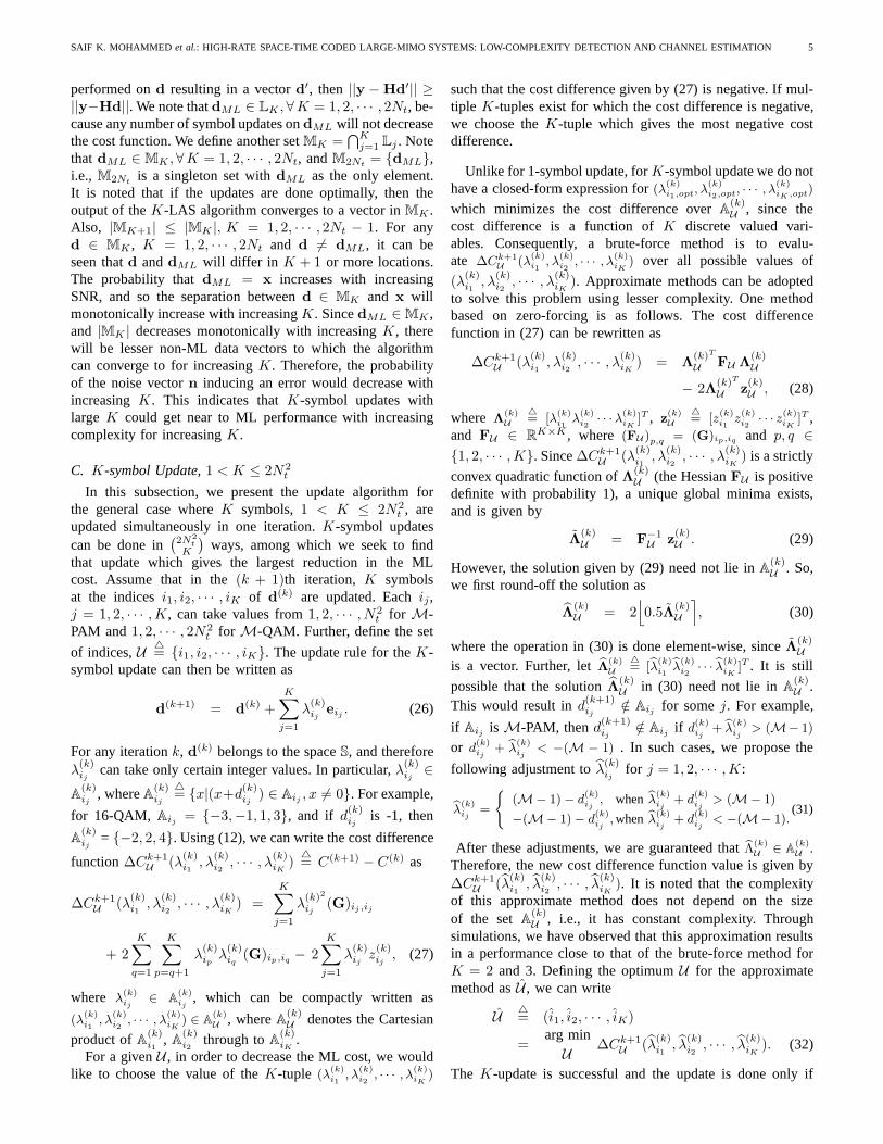
D. Computational Complexity of theM -LAS Algorithm
The complexity of the proposedM -LAS algorithm com-prises of three components, namely,i) computation of theinitial vector d(0), ii) computation ofHTH, and iii) thesearch operation. Figure 1 shows the per-symbol complexityplots as a function ofNt = Nr for 4-QAM at an SNR of 6 dBusing MMSE initial vector. Two good properties of the STBCsfrom CDA are useful in achieving low orders of complexity forthe computation ofd(0) and HTH. They are:i) the weightmatricesA(i)
c ’s are permutation type, and ii) the N2t × N2
t
matrix formed withN2t × 1-sizeda
(i)c vectors as columns is a
scaled unitary matrix. These properties allow the computationof MMSE/ZF initial solution inO(N3
t Nr) complexity, i.e., inO(NtNr) per-symbol complexity since there areN2
t symbolsin one STBC matrix. Likewise, the computation ofHTH canbe done inO(N3
t ) per-symbol complexity.The average per-symbol complexities of the 1-LAS and 2-
LAS search operations areO(N2t ) andO(N2
t log Nt), respec-tively, which can be explained as follows. The average searchcomplexity is the complexity of one search stage times themean number of search stages till the algorithm terminates.For 1-LAS, the number of search stages is always one. Thereare multiple iterations in the search, and in each iterationallpossible
(2N2
t
1
)1-symbol updates are considered. So, the per-
iteration complexity in 1-LAS isO(N2t ), i.e.,O(1) complexity
per symbol. Further, the mean number of iterations beforethe algorithm terminates in 1-LAS was found to beO(N2
t )through simulations. So, the overall per-symbol complexityof 1-LAS is O(N2
t ). In 2-LAS, the complexity of the 2-symbol update dominates over the 1-symbol update. Sincethere are
(2N2
t
2
)possible 2-symbol updates, the complex-
ity of one search stage isO(N4t ), i.e., O(N2
t ) complexityper symbol. The mean number of stages till the algorithmterminates in 2-LAS was found to beO(log Nt) throughsimulations. Therefore, the overall per-symbol complexity of2-LAS is O(N2
t log Nt). These can be observed from Fig.1, where it can be seen that the per-symbol complexity inthe initial vector computation plus the 1-LAS/2-LAS searchoperation isO(N2
t )/O(N2t log Nt); i.e., 1-LAS and 2-LAS
complexity plots run parallel to thec1N2t and c2N
2t log Nt
lines, respectively. With the computation ofHTH included,the complexity order is more thanN2
t . From the slopes ofthe plots in Fig. 1, we find that the overall complexitiesfor Nt = 16 and 32 are proportional toN2.5
t and N2.7t ,
respectively.For the special case of ILL-only STBCs (i.e.,δ = t = 1),
the complexity involved in computingd(0) andHTH can be
2 3 4 5 6 7 85
10
15
20
25
30
log2(N
t)
log 2(N
umbe
r of
ope
ratio
ns p
er s
ymbo
l)
c
1 N
t2
c2 N
t2log(N
t)
c3 N
t3
d(0), HTH, search (1−LAS)
d(0), HTH, search (2−LAS)
d(0), search (1−LAS)
d(0), search (2−LAS)
SNR = 6 dB
Fig. 1. Computational complexity of the proposedM -LAS algorithm indecoding non-orthogonal STBCs from CDA. MMSE initial vector, 4-QAM,SNR = 6 dB.
reduced further. This becomes possible due to the follow-ing property of ILL-only STBCs. LetVa be the complexN2
t × N2t matrix with a
(i)c as its ith column. The com-
putation of d(0) (or HTH) involves multiplication ofVHa
with another vector (or matrix). The columns ofVHa can be
permuted in such a way that the permuted matrix is block-diagonal, where each block is aNt × Nt DFT matrix forδ = t = 1. So, the multiplication ofVH
a by any vectorbecomes equivalent to aNt-point DFT operation, which canbe efficiently computed using FFT inO(Nt log Nt) complex-ity. Using this simplification, the per-symbol complexity ofcomputingHTH is reduced fromO(N3
t ) to O(N2t log Nt).
Computingd(0) using MMSE filter involves the computationof 1
NtVH
a (I ⊗ ((HHc Hc + 1
γNtI)−1HH
c ))yc. The complexityof computing the vector(I ⊗ ((HH
c Hc + 1γNt
I)−1HHc ))yc
is O(N2t Nr), and the complexity of computingVH
a (I ⊗((HH
c Hc + 1γNt
I)−1HHc ))yc is O(N3
t Nr). In the case ofILL-only STBC, because of the above-mentioned property, thecomplexity of computingVH
a (I⊗((HHc Hc+
1γNt
I)−1HHc ))yc
gets reduced toO(N2t log Nt) from O(N3
t Nr). So the to-tal complexity for computingd(0) in ILL-only STBC isO(N2
t Nr) + O(N2t log Nt), which gives a per-symbol com-
plexity of O(Nr)+O(logNt). So, the overall per-symbol com-plexity for 1-LAS detection of ILL-STBCs isO(N2
t log Nt).
E. Generation of Soft Outputs
We propose to generate soft values at theM -LAS outputfor all the individual bits that constitute theM-PAM/M-QAMsymbols as follows. These output values are fed as soft inputsto the decoder in a coded system. Letd = [bx1, bx2, · · · , bx2N2
t],
xi ∈ Ai denote the detected output symbol vector from theM -LAS algorithm. Let the symbolxi map to the bit vectorbi = [bi,1, bi,2, · · · , bi,Ki
]T , whereKi = log2 |Ai|, and bi,j ∈{+1,−1}, i = 1, 2, · · · , 2N2
t and j = 1, 2, · · · , Ki. Let bi,j ∈ R
denote the soft value for thejth bit of the ith symbol. Givend, we need to findbi,j , ∀ (i, j).
SAIF K. MOHAMMED et al.: HIGH-RATE SPACE-TIME CODED LARGE-MIMO SYSTEMS: LOW-COMPLEXITY DETECTION AND CHANNEL ESTIMATION 7
Note that the quantity‖y − Hd‖2 is inversely related tothe likelihood thatd is indeed the transmitted symbol vector.Let the d vector with its jth bit of the ith symbol forcedto +1 be denoted as vectordj+
i . Likewise, let dj−i be the
vectord with its jth bit of the ith symbol forced to -1. Thenthe quantities‖y − Hd
j+i ‖2 and‖y − Hd
j−i ‖2 are inversely
related to the likelihoods that thejth bit of theith transmittedsymbol is +1 and -1, respectively. So, if‖y−Hd
j−i ‖2−‖y−
Hdj+i ‖2 is +ve (or -ve), it indicates that thejth bit of theith
transmitted symbol has a higher likelihood of being +1 (or -1).So, the quantity‖y−Hd
j−i ‖2 −‖y−Hd
j+i ‖2, appropriately
normalized to avoid unbounded increase for increasingNt,can be a good soft value for thejth bit of the ith symbol.With this motivation, we generate the soft output value for thejth bit of the ith symbol as
bi,j =‖y − Hd
j−i ‖2 − ‖y − Hd
j+i ‖2
‖hi‖2, (35)
where the normalization by‖hi‖2 is to contain unboundedincrease ofbi,j for increasingNt. The RHS in the above canbe efficiently computed in terms ofz andG as follows. Sinced
j+i andd
j−
i differ only in the ith entry, we can write
dj−i = d
j+i + λi,jei. (36)
Since we knowdj−i and d
j+i , we know λi,j from (36).
Substituting (36) in (35), we can write
bi,j ‖hi‖2 = ‖y − Hdj+i − λi,jhi‖2 − ‖y − Hd
j+i ‖2
= λ2
i,j‖hi‖2 − 2λi,jhTi (y − Hd
j+i ) (37)
= −λ2
i,j‖hi‖2 − 2λi,jhTi (y − Hd
j−i ). (38)
If bi,j = 1, thendj+i = d and substituting this in (37) and
dividing by ‖hi‖2, we get
bi,j = λ2
i,j − 2λi,j
zi
(G)i,i
. (39)
If bi,j = −1, thendj−i = d and substituting this in (38) and
dividing by ‖hi‖2, we get
bi,j = −λ2
i,j − 2λi,j
zi
(G)i,i
. (40)
It is noted thatz and G are already available upon the ter-mination of theM -LAS algorithm, and hence the complexityof computing bi,j in (39) and (40) is constant. Hence, theoverall complexity in computing the soft values for all thebits is O(Nt log2 M). We also see from (39) and (40) that themagnitude ofbi,j depends uponλi,j . For large-size signal sets,the possible values ofλi,j will also be large in magnitude. Wetherefore have to normalizebi,j for the turbo decoder to func-tion properly. It has been observed through simulations thatnormalizingbi,j by
(λi,j
2
)2resulted in good performance. In
[28], we have shown that this soft decision output generationmethod, when used in large V-BLAST systems, offers about 1to 1.5 dB improvement in coded BER performance comparedto that achieved using hard decision outputs from theM -LASalgorithm. We have observed similar improvements in STBCMIMO systems also. In all coded BER simulations in thispaper, we use the soft outputs proposed here as inputs to the
decoder.
IV. BER PERFORMANCE WITHPERFECTCSIR
In this section, we present the uncoded/turbo coded BERperformance of the proposedM -LAS detector in decodingnon-orthogonal STBCs from CDA, assuming perfect knowl-edge of CSI at the receiver5. In all the BER simulations in thissection, we have assumed that the fade remains constant overone STBC matrix duration and varies i.i.d. from one STBCmatrix duration to the other. We consider two STBC designs;i) ‘FD-ILL’ STBCs where δ = e
√5 j, t = ej in (11.a), and
ii) ‘ILL-only’ STBCs where δ = t = 1. The SNRs in allthe BER performance figures are the average received SNRper received antenna,γ, defined in Sec. II [3]. We have usedMMSE filter as the initial filter in all the simulations.
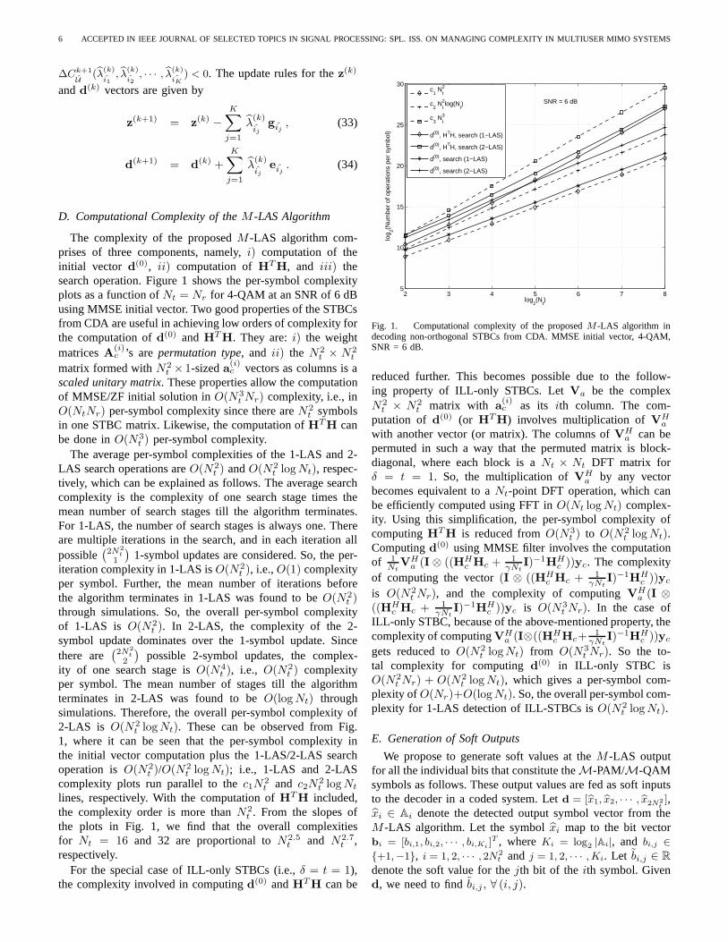
A. Uncoded BER as a Function of IncreasingNt = Nr
In Fig. 2, we plot the uncoded BER performance of theproposed 1-, 2-, and 3-LAS algorithms in decoding ILL-only STBCs (4 × 4, 8 × 8, 16 × 16, 32 × 32 STBCs)for Nt = Nr = 4, 8, 16, 32 and 4-QAM. SISO AWGNperformance (without fading) and MMSE-only performance(i.e., without the search using LAS) are also plotted for com-parison. It can be seen that MMSE-only performance does notimprove with increasing STBC size (i.e., increasingNt = Nr).However, it is interesting to see that, when the proposed searchusing LAS is performed following the MMSE operation, theperformance improves for increasingNt = Nr, illustratingthe performance benefit due to the proposed search strategy.For example, though the LAS detector performs far fromSISO AWGN performance for small number of dimensions(e.g.,4 × 4, 8 × 8 STBCs with 32 and 128 real dimensions,respectively), its large system behavior at increased number ofdimensions (e.g.,16 × 16 and32 × 32 STBCs with 512 and2048 real dimensions, respectively) effectively renders nearSISO AWGN performance; e.g., withNt = Nr = 16, 32,for BERs better than10−3, the LAS detector performs veryclose to SISO AWGN performance. We also observe that 3-LAS performs better than 2-LAS forNt = Nr = 4, 8, and 2-LAS performs better than 1-LAS. Since close to SISO AWGNperformance is achieved with 1-, 2-, or 3-symbol update itself,the cases of more than 3-symbol update, which will result inincreased complexity with diminishing returns in performancegain, are not considered in the performance evaluation.
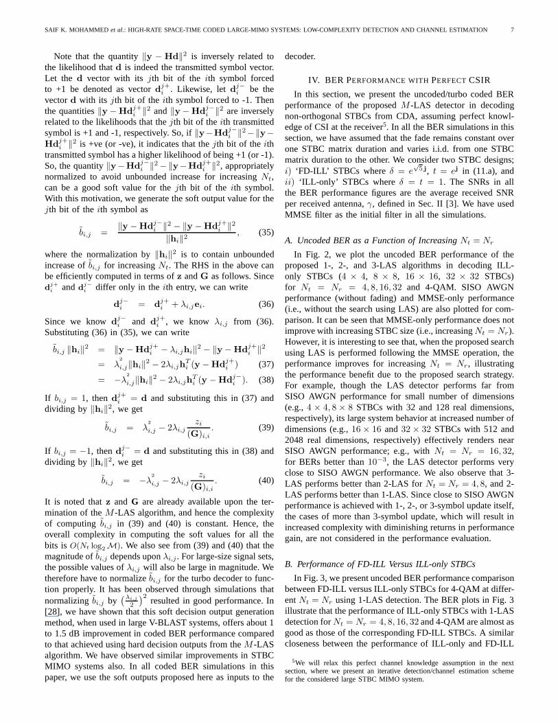
B. Performance of FD-ILL Versus ILL-only STBCs
In Fig. 3, we present uncoded BER performance comparisonbetween FD-ILL versus ILL-only STBCs for 4-QAM at differ-entNt = Nr using 1-LAS detection. The BER plots in Fig. 3illustrate that the performance of ILL-only STBCs with 1-LASdetection forNt = Nr = 4, 8, 16, 32 and 4-QAM are almost asgood as those of the corresponding FD-ILL STBCs. A similarcloseness between the performance of ILL-only and FD-ILL
5We will relax this perfect channel knowledge assumption in the nextsection, where we present an iterative detection/channel estimation schemefor the considered large STBC MIMO system.
8 ACCEPTED IN IEEE JOURNAL OF SELECTED TOPICS IN SIGNAL PROCESSING: SPL. ISS. ON MANAGING COMPLEXITY IN MULTIUSER MIMO SYSTEMS
2 4 6 8 10 12 1410
−6
10−5
10−4
10−3
10−2
10−1
100
Average Received SNR (dB)
Bit
Err
or R
ate
ILL−only STBCs, 4−QAM Nr = Nt, 2Nt bps/Hz
(1) : 4x4 STBC, MMSE−only
(2) : 8x8 STBC, MMSE−only
(3) : 16x16 STBC, MMSE−only
(4) : 32x32 STBC, MMSE−only
4x4 STBC, 1−LAS
8x8 STBC, 1−LAS
16x16 STBC, 1−LAS
(5) : 32x32 STBC, 1−LAS
4x4 STBC, 2−LAS
8x8 STBC, 2−LAS
16x16 STBC, 2−LAS
(6) : 32x32 STBC, 2−LAS
4x4 STBC, 3−LAS
8x8 STBC, 3−LAS
SISO AWGN
(5, 6)
BER improves withincreasing Nr =Nt.
MMSE−only (No LAS)(1, 2, 3, 4)
Fig. 2. Uncoded BER of the proposed 1-LAS, 2-LAS and 3-LAS detectorsfor ILL-only STBCs for differentNt = Nr. 4-QAM, 2Nt bps/Hz. BERimproves asNt = Nr increases and approaches SISO AWGN performancefor large Nt = Nr .
0 5 10 15
10−4
10−3
10−2
10−1
100
Average Received SNR (dB)
Bit
Err
or R
ate
(1, 5)
BER improves withincreasing Nr = Nt.
4−QAM, 1−LAS detectionNr = Nt, 2Nt bps/Hz
(1) : 4x4 ILL−only STBC
(2) : 8x8 ILL−only STBC
(3) : 16x16 ILL−only STBC
(4) : 32x32 ILL−only STBC
(5) : 4x4 FD−ILL STBC
(6) : 8x8 FD−ILL STBC
(7) : 16x16 FD−ILL STBC
(8) : 32x32 FD−ILL STBC
SISO AWGN
(2, 6)
(3, 7)
(4, 8)
Fig. 3. Uncoded BER comparison betweenFD-ILL and ILL-only STBCsfor different Nt = Nr . 4-QAM, 2Nt bps/Hz, 1-LAS detection.ILL-onlySTBCs perform almost same as FD-ILL STBCs.
STBCs is observed in the turbo coded BER performance aswell, which is shown in Fig. 8 for a16 × 16 STBC with 4-QAM and turbo code rates of 1/3, 1/2 and 3/4. This is aninteresting observation, since this suggests that, in suchcases,the computational complexity advantage withδ = t = 1 inILL-only STBCs can be taken advantage of without incurringmuch performance loss compared to FD-ILL STBCs.
0 5 10 15 20 25 3010
−5
10−4
10−3
10−2
10−1
100
Average Received SNR (dB)
Bit
Err
or R
ate
4x4 Perfect code6x6 Perfect code8x8 Perfect code(1): 16x16 Perfect code(2): 32x32 Perfect code4x4 ILL−only STBC6x6 ILL−only STBC8x8 ILL−only STBC(3): 16x16 ILL−only STBC(4): 32x32 ILL−only STBCSISO AWGN
(1, 3)
(2, 4)
4−QAM, 1−LAS detectionNt = Nr, 2Nt bps/Hz
Fig. 4. Uncoded BER comparison betweenperfect codesand ILL-onlySTBCs for differentNt = Nr , 4-QAM, 2Nt bps/Hz, 1-LAS detection.Forsmall dimensions (e.g.,4×4, 6×6, 8×8), perfect codes with 1-LAS detectionperform worse than ILL-only STBCs. For large dimensions (e.g., 16 × 16,32 × 32), ILL-only STBCs and perfect codes perform almost same.
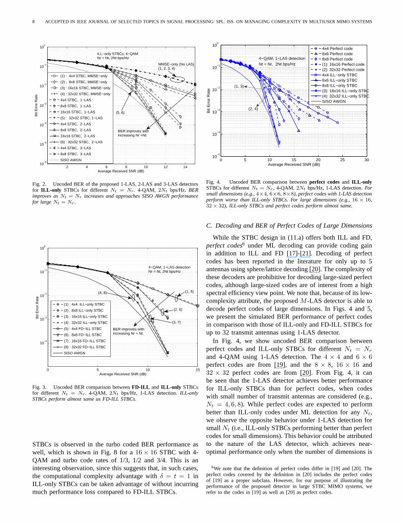
C. Decoding and BER of Perfect Codes of Large Dimensions
While the STBC design in (11.a) offers both ILL and FD,perfect codes6 under ML decoding can provide coding gainin addition to ILL and FD [17]-[21]. Decoding of perfectcodes has been reported in the literature for only up to 5antennas using sphere/lattice decoding [20]. The complexity ofthese decoders are prohibitive for decoding large-sized perfectcodes, although large-sized codes are of interest from a highspectral efficiency view point. We note that, because of its low-complexity attribute, the proposedM -LAS detector is able todecode perfect codes of large dimensions. In Figs. 4 and 5,we present the simulated BER performance of perfect codesin comparison with those of ILL-only and FD-ILL STBCs forup to 32 transmit antennas using 1-LAS detector.
In Fig. 4, we show uncoded BER comparison betweenperfect codes and ILL-only STBCs for differentNt = Nr
and 4-QAM using 1-LAS detection. The4 × 4 and 6 × 6perfect codes are from [19], and the8 × 8, 16 × 16 and32 × 32 perfect codes are from [20]. From Fig. 4, it canbe seen that the 1-LAS detector achieves better performancefor ILL-only STBCs than for perfect codes, when codeswith small number of transmit antennas are considered (e.g.,Nt = 4, 6, 8). While perfect codes are expected to performbetter than ILL-only codes under ML detection for anyNt,we observe the opposite behavior under 1-LAS detection forsmallNt (i.e., ILL-only STBCs performing better than perfectcodes for small dimensions). This behavior could be attributedto the nature of the LAS detector, which achieves near-optimal performance only when the number of dimensions is
6We note that the definition of perfect codes differ in [19] and[20]. Theperfect codes covered by the definition in [20] includes the perfect codesof [19] as a proper subclass. However, for our purpose of illustrating theperformance of the proposed detector in large STBC MIMO systems, werefer to the codes in [19] as well as [20] as perfect codes.
SAIF K. MOHAMMED et al.: HIGH-RATE SPACE-TIME CODED LARGE-MIMO SYSTEMS: LOW-COMPLEXITY DETECTION AND CHANNEL ESTIMATION 9
5 10 15 20 25 30 35 40 4510
−5
10−4
10−3
10−2
10−1
100
Average Received SNR (dB)
Bit
Err
or R
ate
16x16 Perfect code(1) : 16x16 ILL−only STBC(2) : 16x16 FD−ILL STBC32x32 Perfect code(3) : 32x32 ILL−only STBC(4) : 32x32 FD−ILL STBCSISO AWGN
(1, 2)
(3, 4)
16−QAM, 1−LAS detection Nr = Nt, 4Nt bps/Hz.
Fig. 5. Uncoded BER comparison betweenperfect codes, ILL-only , andFD-ILL STBCs for Nt = Nr = 16, 32, 16-QAM, 4Nt bps/Hz, 1-LASdetection.For larger modulation alphabet sizes (e.g., 16 QAM), perfect codeswith 1-LAS detection perform poorer than ILL-only and FD-ILL STBCs.
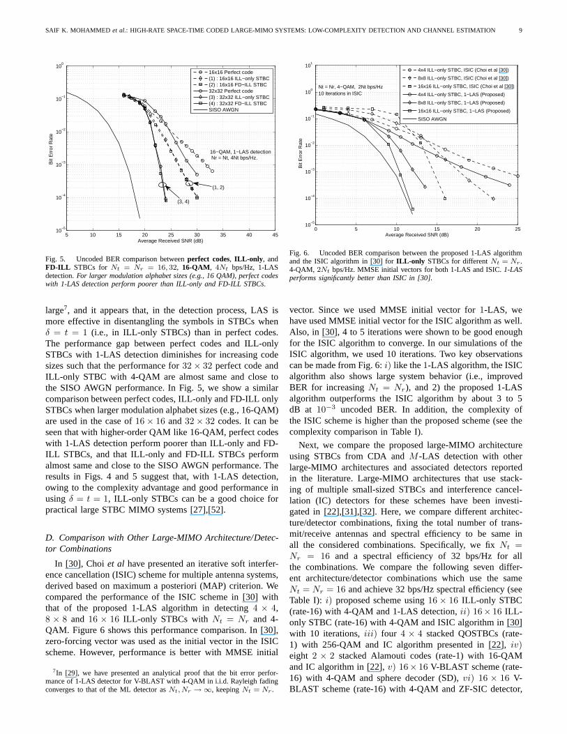
large7, and it appears that, in the detection process, LAS ismore effective in disentangling the symbols in STBCs whenδ = t = 1 (i.e., in ILL-only STBCs) than in perfect codes.The performance gap between perfect codes and ILL-onlySTBCs with 1-LAS detection diminishes for increasing codesizes such that the performance for32 × 32 perfect code andILL-only STBC with 4-QAM are almost same and close tothe SISO AWGN performance. In Fig. 5, we show a similarcomparison between perfect codes, ILL-only and FD-ILL onlySTBCs when larger modulation alphabet sizes (e.g., 16-QAM)are used in the case of16 × 16 and32 × 32 codes. It can beseen that with higher-order QAM like 16-QAM, perfect codeswith 1-LAS detection perform poorer than ILL-only and FD-ILL STBCs, and that ILL-only and FD-ILL STBCs performalmost same and close to the SISO AWGN performance. Theresults in Figs. 4 and 5 suggest that, with 1-LAS detection,owing to the complexity advantage and good performance inusing δ = t = 1, ILL-only STBCs can be a good choice forpractical large STBC MIMO systems [27],[52].
D. Comparison with Other Large-MIMO Architecture/Detec-tor Combinations
In [30], Choi et al have presented an iterative soft interfer-ence cancellation (ISIC) scheme for multiple antenna systems,derived based on maximum a posteriori (MAP) criterion. Wecompared the performance of the ISIC scheme in [30] withthat of the proposed 1-LAS algorithm in detecting4 × 4,8 × 8 and 16 × 16 ILL-only STBCs with Nt = Nr and 4-QAM. Figure 6 shows this performance comparison. In [30],zero-forcing vector was used as the initial vector in the ISICscheme. However, performance is better with MMSE initial
7In [29], we have presented an analytical proof that the bit error perfor-mance of 1-LAS detector for V-BLAST with 4-QAM in i.i.d. Rayleigh fadingconverges to that of the ML detector asNt, Nr → ∞, keepingNt = Nr .
0 5 10 15 20 2510
−5
10−4
10−3
10−2
10−1
100
101
Average Received SNR (dB)
Bit
Err
or R
ate
4x4 ILL−only STBC, ISIC (Choi et al [30])
8x8 ILL−only STBC, ISIC (Choi et al [30])
16x16 ILL−only STBC, ISIC (Choi et al [30])
4x4 ILL−only STBC, 1−LAS (Proposed)
8x8 ILL−only STBC, 1−LAS (Proposed)
16x16 ILL−only STBC, 1−LAS (Proposed)
SISO AWGN
Nt = Nr, 4−QAM, 2Nt bps/Hz10 iterations in ISIC
Fig. 6. Uncoded BER comparison between the proposed 1-LAS algorithmand the ISIC algorithm in [30] forILL-only STBCs for differentNt = Nr.4-QAM, 2Nt bps/Hz. MMSE initial vectors for both 1-LAS and ISIC.1-LASperforms significantly better than ISIC in [30].
vector. Since we used MMSE initial vector for1-LAS, wehave used MMSE initial vector for the ISIC algorithm as well.Also, in [30], 4 to 5 iterations were shown to be good enoughfor the ISIC algorithm to converge. In our simulations of theISIC algorithm, we used 10 iterations. Two key observationscan be made from Fig. 6:i) like the1-LAS algorithm, the ISICalgorithm also shows large system behavior (i.e., improvedBER for increasingNt = Nr), and 2) the proposed 1-LASalgorithm outperforms the ISIC algorithm by about 3 to 5dB at 10−3 uncoded BER. In addition, the complexity ofthe ISIC scheme is higher than the proposed scheme (see thecomplexity comparison in Table I).
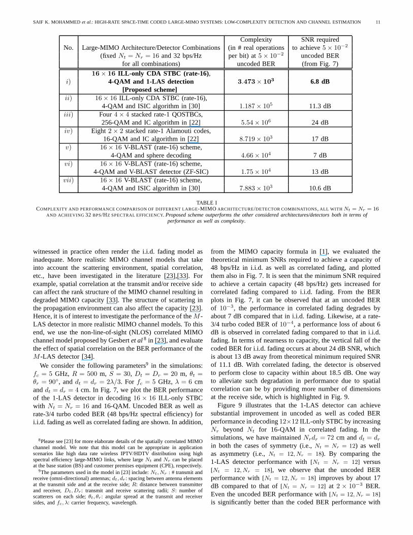
Next, we compare the proposed large-MIMO architectureusing STBCs from CDA andM -LAS detection with otherlarge-MIMO architectures and associated detectors reportedin the literature. Large-MIMO architectures that use stack-ing of multiple small-sized STBCs and interference cancel-lation (IC) detectors for these schemes have been investi-gated in [22],[31],[32]. Here, we compare different architec-ture/detector combinations, fixing the total number of trans-mit/receive antennas and spectral efficiency to be same inall the considered combinations. Specifically, we fixNt =Nr = 16 and a spectral efficiency of 32 bps/Hz for allthe combinations. We compare the following seven differ-ent architecture/detector combinations which use the sameNt = Nr = 16 and achieve 32 bps/Hz spectral efficiency (seeTable I): i) proposed scheme using16 × 16 ILL-only STBC(rate-16) with 4-QAM and 1-LAS detection,ii) 16× 16 ILL-only STBC (rate-16) with 4-QAM and ISIC algorithm in [30]with 10 iterations,iii) four 4 × 4 stacked QOSTBCs (rate-1) with 256-QAM and IC algorithm presented in [22],iv)eight 2 × 2 stacked Alamouti codes (rate-1) with 16-QAMand IC algorithm in [22],v) 16× 16 V-BLAST scheme (rate-16) with 4-QAM and sphere decoder (SD),vi) 16 × 16 V-BLAST scheme (rate-16) with 4-QAM and ZF-SIC detector,
10 ACCEPTED IN IEEE JOURNAL OF SELECTED TOPICS IN SIGNAL PROCESSING: SPL. ISS. ON MANAGING COMPLEXITY IN MULTIUSER MIMO SYSTEMS
0 5 10 15 20 25 30 35 4010
−5
10−4
10−3
10−2
10−1
100
101
102
Average Received SNR (dB)
Bit
Err
or R
ate
16x16 V−BLAST, 4−QAM, ZF−SIC detector
Four 4x4 Stacked QOSTBCs, 256−QAM, IC in [22]
Eight 2x2 Stacked Alamouti codes, 16−QAM, IC in [22]
16x16 V−BLAST, 4−QAM, ISIC with 10 iterations in [30]
16x16 ILL−only STBC, 4−QAM, ISIC with 10 iterations in [30]
16x16 V−BLAST, 4−QAM, Sphere decoder
16x16 ILL−only STBC, 4−QAM, 1−LAS detector (Proposed)
SISO AWGN, 4−QAM
For all architecturesNr = Nt = 16Spectral efficiency = 32 bps/Hz
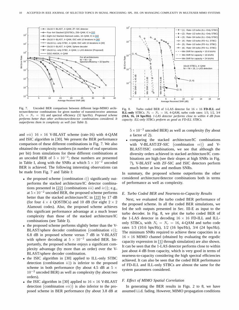
Fig. 7. Uncoded BER comparison between different large-MIMO archi-tecture/detector combinations for given number of transmit/receive antennas(Nt = Nr = 16) and spectral efficiency (32 bps/Hz).Proposed schemeperforms better than other architecture/detector combinations considered. Itoutperforms them in complexity as well (see Table I).
and vii) 16 × 16 V-BLAST scheme (rate-16) with 4-QAMand ISIC algorithm in [30]. We present the BER performancecomparison of these different combinations in Fig. 7. We alsoobtained the complexity numbers (in number of real operationsper bit) from simulations for these different combinationsatan uncoded BER of5 × 10−2; these numbers are presentedin Table I, along with the SNRs at which5 × 10−2 uncodedBER is achieved. The following interesting observations canbe made from Fig. 7 and Table I:
• the proposed scheme(combinationi)
)significantly out-
performs the stacked architecture/IC detector combina-tions presented in [22]
(combinationsiii) andiv)
); e.g.,
at 5×10⁻² uncoded BER, the proposed scheme performsbetter than the stacked architecture/IC in [22] by 17 dB(for four 4 × 4 QOSTBCs) and 10 dB (for eight2 × 2Alamouti codes). Also, the proposed scheme achievesthis significant performance advantage at a much lessercomplexity than those of the stacked architecture/ICcombinations (see Table I).
• the proposed scheme performs slightly better than the V-BLAST/sphere decoder combination
(combinationv)
);
6.8 dB in proposed scheme versus 7 dB in V-BLASTwith sphere decoding at5 × 10−2 uncoded BER. Im-portantly, the proposed scheme enjoys a significant com-plexity advantage (by more than an order) over the V-BLAST/sphere decoder combination.
• the ISIC algorithm in [30] applied to ILL-only STBCdetection (combinationii)) is inferior to the proposedscheme in both performance (by about 4.5 dB at5 ×10−2 uncoded BER) as well as complexity (by about twoorders).
• the ISIC algorithm in [30] applied to16× 16 V-BLASTdetection
(combinationvii)
)is also inferior to the pro-
posed scheme in BER performance (by about 3.8 dB at
−2 0 2 4 6 8 10 12 14 16 18
10−4
10−3
10−2
10−1
100
Average Received SNR (dB)
Bit
Err
or R
ate
16x16 STBCs, 4−QAMNr = Nt = 16, 1−LAS detection
Min
SN
R =
−1.
45 d
B
Min
SN
R =
1.2
dB
Min
SN
R =
4.3
dB
(1) : Rate−1/3 turbo (ILL−Only STBC)
(2) : Rate−1/2 turbo (ILL−Only STBC)
(3) : Rate−3/4 turbo (ILL−Only STBC)
(4) : Rate−1/3 turbo (FD−ILL STBC)
(5) : Rate−1/2 turbo (FD−ILL STBC)
(6) : Rate−3/4 turbo (FD−ILL STBC)
Min SNR for capacity = 10.6 b/s/Hz
Min SNR for capacity = 16 b/s/Hz
Min SNR for capacity = 24 b/s/Hz
(2, 5)
(1, 4)
(3, 6)
Fig. 8. Turbo coded BER of 1-LAS detector for16 × 16 FD-ILL andILL-only STBCs.Nt = Nr = 16, 4-QAM, turbo code rates: 1/3, 1/2, 3/4(10.6, 16, 24 bps/Hz). 1-LAS detector performs close to within 4 dB fromcapacity. ILL-only STBCs preform as good as FD-ILL STBCs.
5×10⁻² uncoded BER) as well as complexity (by abouta factor of 2).
• comparing the stacked architecture/IC combinationswith V-BLAST/ZF-SIC
(combination vi)
)and V-
BLAST/ISIC combinations, we see that although thediversity orders achieved in stacked architecture/IC com-binations are high (see their slopes at high SNRs in Fig.7), V-BLAST with ZF-SIC and ISIC detectors performmuch better at low and medium SNRs.
In summary, the proposed scheme outperforms the otherconsidered architecture/detector combinations both in termsof performance as well as complexity.
E. Turbo Coded BER and Nearness-to-Capacity Results
Next, we evaluated the turbo coded BER performance ofthe proposed scheme. In all the coded BER simulations, wefed the soft outputs presented in Sec. III-E as input to theturbo decoder. In Fig. 8, we plot the turbo coded BER ofthe 1-LAS detector in decoding16 × 16 FD-ILL and ILL-only STBCs, withNt = Nr = 16, 4-QAM and turbo coderates 1/3 (10.6 bps/Hz), 1/2 (16 bps/Hz), 3/4 (24 bps/Hz).The minimum SNRs required to achieve these capacities in a16 × 16 MIMO channel (obtained by evaluating the ergodiccapacity expression in [1] through simulation) are also shown.It can be seen that the 1-LAS detector performs close to withinjust about 4 dB from capacity, which is very good in terms ofnearness-to-capacity considering the high spectral efficienciesachieved. It can also be seen that the coded BER performanceof FD-ILL and ILL-only STBCs are almost the same for thesystem parameters considered.
F. Effect of MIMO Spatial Correlation
In generating the BER results in Figs. 2 to 8, we haveassumed i.i.d. fading. However, MIMO propagation conditions
SAIF K. MOHAMMED et al.: HIGH-RATE SPACE-TIME CODED LARGE-MIMO SYSTEMS: LOW-COMPLEXITY DETECTION AND CHANNEL ESTIMATION 11
Complexity SNR requiredNo. Large-MIMO Architecture/Detector Combinations(in # real operations to achieve5 × 10−2
(fixed Nt = Nr = 16 and 32 bps/Hz per bit) at5 × 10−2 uncoded BERfor all combinations) uncoded BER (from Fig. 7)
16× 16 ILL-only CDA STBC (rate-16) ,i) 4-QAM and 1-LAS detection 3.473× 10³ 6.8 dB
[Proposed scheme]ii) 16 × 16 ILL-only CDA STBC (rate-16),
4-QAM and ISIC algorithm in [30] 1.187× 10⁵ 11.3 dBiii) Four 4 × 4 stacked rate-1 QOSTBCs,
256-QAM and IC algorithm in [22] 5.54 × 10⁶ 24 dBiv) Eight 2 × 2 stacked rate-1 Alamouti codes,
16-QAM and IC algorithm in [22] 8.719× 10³ 17 dBv) 16 × 16 V-BLAST (rate-16) scheme,
4-QAM and sphere decoding 4.66 × 10⁴ 7 dBvi) 16 × 16 V-BLAST (rate-16) scheme,
4-QAM and V-BLAST detector (ZF-SIC) 1.75 × 10⁴ 13 dBvii) 16 × 16 V-BLAST (rate-16) scheme,
4-QAM and ISIC algorithm in [30] 7.883× 10³ 10.6 dB
TABLE ICOMPLEXITY AND PERFORMANCE COMPARISON OF DIFFERENT LARGE-MIMO ARCHITECTURE/DETECTOR COMBINATIONS, ALL WITH Nt = Nr = 16
AND ACHIEVING 32 BPS/HZ SPECTRAL EFFICIENCY. Proposed scheme outperforms the other considered architectures/detectors both in terms ofperformance as well as complexity.
witnessed in practice often render the i.i.d. fading model asinadequate. More realistic MIMO channel models that takeinto account the scattering environment, spatial correlation,etc., have been investigated in the literature [23],[33]. Forexample, spatial correlation at the transmit and/or receive sidecan affect the rank structure of the MIMO channel resulting indegraded MIMO capacity [33]. The structure of scattering inthe propagation environment can also affect the capacity [23].Hence, it is of interest to investigate the performance of theM -LAS detector in more realistic MIMO channel models. To thisend, we use the non-line-of-sight (NLOS) correlated MIMOchannel model proposed by Gesbertet al8 in [23], and evaluatethe effect of spatial correlation on the BER performance of theM -LAS detector [34].
We consider the following parameters9 in the simulations:fc = 5 GHz, R = 500 m, S = 30, Dt = Dr = 20 m, θt =θr = 90◦, anddt = dr = 2λ/3. For fc = 5 GHz, λ = 6 cmanddt = dr = 4 cm. In Fig. 7, we plot the BER performanceof the 1-LAS detector in decoding16 × 16 ILL-only STBCwith Nt = Nr = 16 and 16-QAM. Uncoded BER as well asrate-3/4 turbo coded BER (48 bps/Hz spectral efficiency) fori.i.d. fading as well as correlated fading are shown. In addition,
8Please see [23] for more elaborate details of the spatially correlated MIMOchannel model. We note that this model can be appropriate in applicationscenarios like high data rate wireless IPTV/HDTV distribution using highspectral efficiency large-MIMO links, where largeNt andNr can be placedat the base station (BS) and customer premises equipment (CPE), respectively.
9The parameters used in the model in [23] include:Nt, Nr : # transmit andreceive (omni-directional) antennas;dt, dr : spacing between antenna elementsat the transmit side and at the receive side;R: distance between transmitterand receiver,Dt, Dr: transmit and receive scattering radii;S: number ofscatterers on each side;θt, θr : angular spread at the transmit and receiversides, andfc, λ: carrier frequency, wavelength.
from the MIMO capacity formula in [1], we evaluated thetheoretical minimum SNRs required to achieve a capacity of48 bps/Hz in i.i.d. as well as correlated fading, and plottedthem also in Fig. 7. It is seen that the minimum SNR requiredto achieve a certain capacity (48 bps/Hz) gets increased forcorrelated fading compared to i.i.d. fading. From the BERplots in Fig. 7, it can be observed that at an uncoded BERof 10−3, the performance in correlated fading degrades byabout 7 dB compared that in i.i.d. fading. Likewise, at a rate-3/4 turbo coded BER of10−4, a performance loss of about 6dB is observed in correlated fading compared to that in i.i.d.fading. In terms of nearness to capacity, the vertical fall of thecoded BER for i.i.d. fading occurs at about 24 dB SNR, whichis about 13 dB away from theoretical minimum required SNRof 11.1 dB. With correlated fading, the detector is observedto perform close to capacity within about 18.5 dB. One wayto alleviate such degradation in performance due to spatialcorrelation can be by providing more number of dimensionsat the receive side, which is highlighted in Fig. 9.
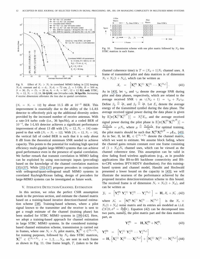
Figure 9 illustrates that the 1-LAS detector can achievesubstantial improvement in uncoded as well as coded BERperformance in decoding12×12 ILL-only STBC by increasingNr beyond Nt for 16-QAM in correlated fading. In thesimulations, we have maintainedNrdr = 72 cm anddt = dr
in both the cases of symmetry (i.e.,Nt = Nr = 12) as wellas asymmetry (i.e.,Nt = 12, Nr = 18). By comparing the1-LAS detector performance with[Nt = Nr = 12] versus[Nt = 12, Nr = 18], we observe that the uncoded BERperformance with[Nt = 12, Nr = 18] improves by about 17dB compared to that of[Nt = Nr = 12] at 2 × 10⁻³ BER.Even the uncoded BER performance with[Nt = 12, Nr = 18]is significantly better than the coded BER performance with
12 ACCEPTED IN IEEE JOURNAL OF SELECTED TOPICS IN SIGNAL PROCESSING: SPL. ISS. ON MANAGING COMPLEXITY IN MULTIUSER MIMO SYSTEMS
5 10 15 20 25 30 35 40 45 5010
−5
10−4
10−3
10−2
10−1
100
Average Received SNR (dB)
Bit
Err
or R
ate
Nt = Nr = 12, uncodedNt = 12, Nr = 18, uncodedUncoded SISO AWGNNt = Nr = 12, rate−3/4 turbo codedNt = 12, Nr = 18, rate−3/4 turbo codedMin. SNR for Capacity = 36 bps/Hz (Nt = Nr = 12)Min. SNR for capacity = 36 bps/Hz (Nt = 12, Nr = 18)
12x12 ILL−only STBC, 16−QAMNt = 12, Nr = 12,18, 1−LAS detection
Correlated MIMO chl parameters:
Nrd
r = 72 cm, d
t = d
r
Dr = D
t = 20 m
fc = 5 GHz, R = 500 m, S = 30
θt = θ
r = 90 deg.
Min
. SN
R =
12.
6 dB
(N
r =
12)
Min
. SN
R =
9.4
dB
(N
r =
18)
Fig. 9. Effect ofNr > Nt in correlated MIMO fading in [23] keepingNrdr constant anddt = dr . Nrdr = 72 cm, fc = 5 GHz, R = 500 m,S = 30, Dt = Dr = 20 m, θt = θr = 90◦, 12 × 12 ILL-only STBC,Nt = 12, Nr = 12, 18, 16-QAM, rate-3/4 turbo code,36 bps/Hz. Increasing# receive dimensions alleviates the loss due to spatial correlation.
[Nt = Nr = 12] by about 11.5 dB at10−3 BER. Thisimprovement is essentially due to the ability of the 1-LASdetector to effectively pick up the additional diversity ordersprovided by the increased number of receive antennas. Witha rate-3/4 turbo code (i.e., 36 bps/Hz), at a coded BER of10−4, the 1-LAS detector achieves a significant performanceimprovement of about 13 dB with [Nt = 12, Nr = 18] com-pared to that with[Nt = Nr = 12]. With [Nt = 12, Nr = 18],the vertical fall of coded BER is such that it is only about8 dB from the theoretical minimum SNR needed to achievecapacity. This points to the potential for realizing high spectralefficiency multi-gigabit large-MIMO systems that can achievegood performance even in the presence of spatial correlation.We further remark that transmit correlation in MIMO fadingcan be exploited by using non-isotropic inputs (precoding)based on the knowledge of the channel correlation matrices[35]-[37]. While [35]-[37] propose precoders in conjunctionwith orthogonal/quasi-orthogonal small MIMO systems incorrelated Rayleigh/Ricean fading, design of precoders forlarge-MIMO systems can be investigated as future work.
V. I TERATIVE DETECTION/CHANNEL ESTIMATION
In this section, we relax the perfect CSIR assumptionmade in the previous section, and estimate the channel matrixbased on a training-based iterative detection/channel estima-tion scheme [38]. Training-based schemes, where a pilotsignal known to the transmitter and the receiver is sent toget a rough estimate of the channel (training phase) hasbeen studied for STBC MIMO systems in [39]-[42]. Here,we adopt a training-based approach for channel estimationin large STBC MIMO systems. In the considered training-based channel estimation scheme, transmission is carried outin frames, where oneNt × Nt pilot matrix, X(P)
c ∈ CNt×Nt ,for training purposes, followed byNd data STBC matrices,X
(i)c ∈ C
Nt×Nt , i = 1, 2, ..., Nd, are sent in each frameas shown in Fig. 11. One frame length,T , (taken to be the
������
��������������������
������������������������������
������������������������������
����������
����������
������������������������
������������������������
������������������������
��������
���
���
����
��
���
���
��������
��������
time
Data STBCs
Space
MatrixMatrixPilot
1 Pilot
Data STBCs
1 Frame
Nt Nt Nd �NtNd
Fig. 10. Transmission scheme with one pilot matrix followedby Nd dataSTBC matrices in each frame.
channel coherence time) isT = (Nd + 1)Nt channel uses. Aframe of transmitted pilot and data matrices is of dimensionNt × Nt(1 + Nd), which can be written as
Xc =[X(P)
c X(1)c X(2)
c · · · X(Nd)c
]. (41)
As in [43], let γp and γd denote the average SNR duringpilot and data phases, respectively, which are related to theaverage received SNRγ as γ(Nd + 1) = γp + Ndγd.
Define βp△=
γp
γ, and βd
△= γd
γ. Let Es denote the average
energy of the transmitted symbol during the data phase. Theaverage received signal power during the data phase is given
by E[tr(X
(i)c X
(i)c
H)]= N2
t Es, and the average received
signal power during the pilot phase isE[tr(X
(P)c X
(P)c
H)]=
N2t Esβp
βd= µNt, whereµ
△=
NtEsβp
βd. For optimal training,
the pilot matrix should be such thatX(P)c X(P)
c
H= µINt
[43].As in Sec. II, letHc ∈ C
Nr×Nt denote the channel matrix,which we want to estimate. We assume block fading, wherethe channel gains remain constant over one frame consistingof (1 + Nd)Nt channel uses, which can be viewed as thechannel coherence time. This assumption can be valid inslow fading fixed wireless applications (e.g., as in possibleapplications like BS-to-BS backbone connectivity and BS-to-CPE wireless IPTV/HDTV distribution). For this training-based system and channel model, Hassibi and Hochwaldpresented a lower bound on the capacity in [43]; we willillustrate the nearness of the performance achieved by theproposed iterative detection/estimation scheme to this bound.The received frame is of dimensionNr × Nt(1 + Nd), andcan be written as
Yc =[Y(P)
c Y(1)c Y(2)
c · · · Y(Nd)c
]= Hc Xc + Nc , (42)
where Nc =hN(P)
c N(1)c N
(2)c · · · N
(Nd)c
iis the Nr ×
Nt(1 + Nd) noise matrix and its entries are modeled as i.i.d.CN (0, σ2 = NtEs
γβd). Equation (42) can be decomposed into
two parts, namely, the pilot matrix part and the data matricespart, as
Y(P)c = HcX
(P)c + N(P)
c , (43)
Y(D)c =
[Y(1)
c Y(2)c · · · Y(Nd)
c
]
= Hc
[X(1)
c X(2)c · · · X(Nd)
c
]+[N(1)
c N(2)c · · · N(Nd)
c
].(44)
SAIF K. MOHAMMED et al.: HIGH-RATE SPACE-TIME CODED LARGE-MIMO SYSTEMS: LOW-COMPLEXITY DETECTION AND CHANNEL ESTIMATION 13
A. MMSE Estimation Scheme
A straight-forward way to achieve detection of data symbolswith estimated channel coefficients is as follows:
1) Estimate the channel gains via anMMSE estimatorfromthe signal received during the firstNt channel uses (i.e.,during pilot transmission); i.e., givenY(P)
c andX(P)c , an
estimate of the channel matrixHc is found as
Hestc = Y(P)
c (X(P)c )H
[σ2INt
+ X(P)c (X(P)
c )H]−1
. (45)
2) Use the aboveHestc in place ofHc in the LAS algorithm
(as described in Sections II and III) and detect thetransmitted data symbols.
We refer to the above scheme as the‘MMSE estimationscheme.’In the absence of the knowledge ofσ2, a zero-forcingestimate can be obtained at the cost of some performanceloss compared to the MMSE estimate. The performance ofthe estimator can be improved by using a cyclic minimizationtechnique for minimizing the ML metric [44].
B. Proposed Iterative Detection/Estimation Scheme
Techniques that employ iterations between channel estima-tion and detection can offer improved performance. Iterativereceiver algorithms are attractive to achieve a good tradeoffbetween performance and complexity [45]-[51]. In [45]-[47],receivers that iterate between channel estimation, multiuserdetection and channel decoding in coded CDMA systems arepresented. Similar iterative techniques in the context of MIMOand MIMO-OFDM systems are presented in [48]-[51]. Here,we propose an iterative scheme, where we iterate betweenchannel estimation and detection in the considered large STBCMIMO system. The proposed scheme works as follows:
1) Obtain an initial estimate of the channel matrix usingthe MMSE estimator in (45) from the pilot part.
2) Using the estimated channel matrix, detect the dataSTBC matricesX(i)
c , i = 1, 2, · · · , Nd using the LASdetector. Substituting these detected STBC matrices into(41), formX est
c .3) Re-estimate the channel matrix usingX est
c from theprevious step, via
Hestc = Yc(X est
c )H[σ2INt
+ X estc (X est
c )H]−1
. (46)
4) Iterate steps 2 and 3 for a specified number of iterations.
The total complexity of obtaining the MMSE estimate of thechannel matrixHest
c in (45) and (46) isO(N2t Nr) + O(N3
t ),which is less than the total complexity of 1-LAS detection ofO(N4
t log Nt) for ILL-only STBCs.
C. BER Performance with Estimated CSIR
We evaluated the BER performance of the 1-LAS detectorusing estimated CSIR, where we estimate the channel gainmatrix through the training-based estimation schemes describ-ed in the previous two subsections. We consider the BERperformance under three scenarios, namely,i) under perfectCSIR, ii) under CSIR estimated using the MMSE estimationscheme in Sec. V-A, andiii) under CSIR estimated using the
−4 −2 0 2 4 6 8 10 12 14 160
10
20
30
40
50
60
70
Average SNR (dB)
Erg
odic
Cap
acity
(bp
s/H
z)
Perfect CSIR1P + 8D (H−H bound)1P + 1D (H−H bound)
16 x 16 MIMO Channel
24 bps/Hz21.3 bps/Hz
12 bps/Hz
7.7
dB
4.3
dB
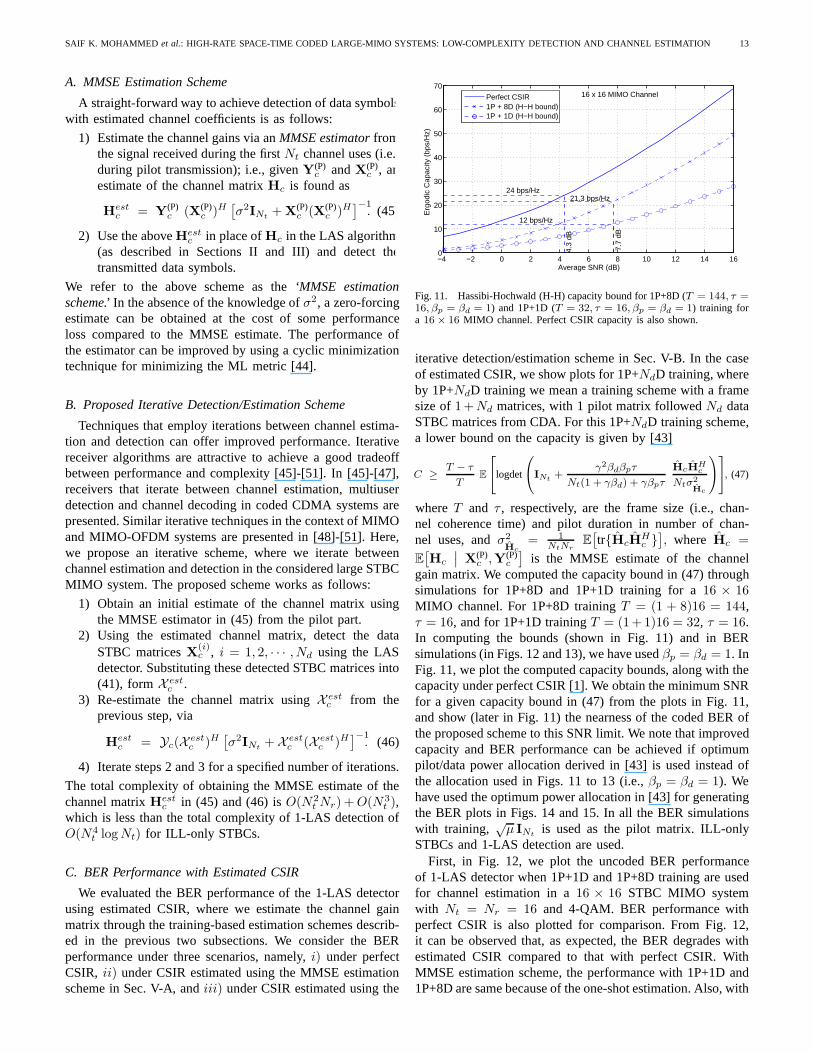
Fig. 11. Hassibi-Hochwald (H-H) capacity bound for 1P+8D (T = 144, τ =16, βp = βd = 1) and 1P+1D (T = 32, τ = 16, βp = βd = 1) training fora 16 × 16 MIMO channel. Perfect CSIR capacity is also shown.
iterative detection/estimation scheme in Sec. V-B. In the caseof estimated CSIR, we show plots for 1P+NdD training, whereby 1P+NdD training we mean a training scheme with a framesize of1+Nd matrices, with 1 pilot matrix followedNd dataSTBC matrices from CDA. For this 1P+NdD training scheme,a lower bound on the capacity is given by [43]
C ≥T − τ
TE
2
4logdet
0
@INt+
γ2βdβpτ
Nt(1 + γβd) + γβpτ
HcHHc
Ntσ2Hc
1
A
3
5, (47)
whereT and τ , respectively, are the frame size (i.e., chan-nel coherence time) and pilot duration in number of chan-nel uses, andσ2
Hc= 1
NtNrE[tr{HcH
Hc }], where Hc =
E[Hc
∣∣ X(P)c ,Y(P)
c
]is the MMSE estimate of the channel
gain matrix. We computed the capacity bound in (47) throughsimulations for 1P+8D and 1P+1D training for a16 × 16MIMO channel. For 1P+8D trainingT = (1 + 8)16 = 144,τ = 16, and for 1P+1D trainingT = (1+1)16 = 32, τ = 16.In computing the bounds (shown in Fig. 11) and in BERsimulations (in Figs. 12 and 13), we have usedβp = βd = 1. InFig. 11, we plot the computed capacity bounds, along with thecapacity under perfect CSIR [1]. We obtain the minimum SNRfor a given capacity bound in (47) from the plots in Fig. 11,and show (later in Fig. 11) the nearness of the coded BER ofthe proposed scheme to this SNR limit. We note that improvedcapacity and BER performance can be achieved if optimumpilot/data power allocation derived in [43] is used insteadofthe allocation used in Figs. 11 to 13 (i.e.,βp = βd = 1). Wehave used the optimum power allocation in [43] for generatingthe BER plots in Figs. 14 and 15. In all the BER simulationswith training,
õ INt
is used as the pilot matrix. ILL-onlySTBCs and 1-LAS detection are used.
First, in Fig. 12, we plot the uncoded BER performanceof 1-LAS detector when 1P+1D and 1P+8D training are usedfor channel estimation in a16 × 16 STBC MIMO systemwith Nt = Nr = 16 and 4-QAM. BER performance withperfect CSIR is also plotted for comparison. From Fig. 12,it can be observed that, as expected, the BER degrades withestimated CSIR compared to that with perfect CSIR. WithMMSE estimation scheme, the performance with 1P+1D and1P+8D are same because of the one-shot estimation. Also, with
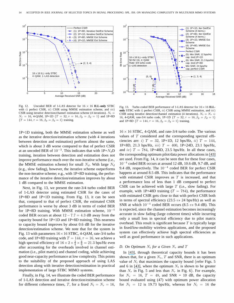
14 ACCEPTED IN IEEE JOURNAL OF SELECTED TOPICS IN SIGNAL PROCESSING: SPL. ISS. ON MANAGING COMPLEXITY IN MULTIUSER MIMO SYSTEMS
0 5 10 15 20 25
10−4
10−3
10−2
10−1
100
Average Received SNR (dB)
Bit
Err
or R
ate
Perfect CSIR(1): 1P+8D, Iterative Det/Est Scheme(2): 1P+1D, Iterative Det/Est Scheme(3): 1P+8D, MMSE Est Scheme(4): 1P+1D, MMSE Est Scheme
16 x 16 ILL−only STBC4−QAM, 1−LAS detection
(2, 3, 4)
Fig. 12. Uncoded BER of 1-LAS detector for16 × 16 ILL-only STBCwith i) perfect CSIR,ii) CSIR using MMSE estimation scheme, andiii)CSIR using iterative detection/channel estimation scheme(4 iterations).Nt =Nr = 16, 4-QAM, 1P+1D
`
T = 32, τ = 16, βp = βd = 1´
and 1P+8D`
T = 144, τ = 16, βp = βd = 1´
training.
1P+1D training, both the MMSE estimation scheme as wellas the iterative detection/estimation scheme (with 4 iterationsbetween detection and estimation) perform almost the same,which is about 3 dB worse compared to that of perfect CSIRat an uncoded BER of10−3. This indicates that with 1P+NdDtraining, iteration between detection and estimation doesnotimprove performance much over the non-iterative scheme (i.e.,the MMSE estimation scheme) for smallNd. With largeNd
(e.g., slow fading), however, the iterative scheme outperformsthe non-iterative scheme; e.g., with 1P+8D training, the perfor-mance of the iterative detection/estimation improves by about1 dB compared to the MMSE estimation.
Next, in Fig. 13, we present the rate-3/4 turbo coded BERof 1-LAS detector using estimated CSIR for the cases of1P+8D and 1P+1D training. From Fig. 13, it can be seenthat, compared to that of perfect CSIR, the estimated CSIRperformance is worse by about 3 dB in terms of coded BERfor 1P+8D training. With MMSE estimation scheme,10−4
coded BER occurs at about12− 7.7 = 4.3 dB away from thecapacity bound for 1P+1D and 1P+8D training. This nearnessto capacity bound improves by about 0.6 dB for the iterativedetection/estimation scheme. We note that for the system inFig. 13 with parameters16×16 STBC, 4-QAM, rate-3/4 turbocode, and 1P+8D training withT = 144, τ = 16, we achieve ahigh spectral efficiency of16×2× 3
4 × 89 = 21.3 bps/Hz even
after accounting for the overheads involved in channel esti-mation (i.e., pilot matrix) and channel coding, while achievinggood near-capacity performance at low complexity. This pointsto the suitability of the proposed approach of using LASdetection along with iterative detection/estimation in practicalimplementation of large STBC MIMO systems.
Finally, in Fig. 14, we illustrate the coded BER performanceof 1-LAS detection and iterative detection/estimation schemefor different coherence times,T , for a fixedNt = Nr = 16,
4 6 8 10 12 14 16 1810
−5
10−4
10−3
10−2
10−1
100
Average Received SNR (dB)
Bit
Err
or R
ate
(1): 1P+1D, Iter Det/EstScheme (4 iterns.)(2): 1P+8D, Iter Det/EstScheme (4 iterns.)(3): 1P+1D, MMSE EstScheme(4): 1P+8D, MMSE EstSchemePerfect CSIR(5): Min SNR; 12 bps/Hzcap. bnd;1P+1D(6): Min SNR; 21.3 bps/Hzcap. bnd;1P+8DMin SNR; 24 bps/Hzcap.;perfect CSIR
16 x 16 ILL−only STBCNt=Nr=16, 4−QAMRate−3/4 turbo code1−LAS detection
4.3
dB
7.7
dB
(1, 3, 4)(5, 6)
Fig. 13. Turbo coded BER performance of 1-LAS detector for16×16 ILL-only STBC with i) perfect CSIR,ii) CSIR using MMSE estimation, andiii)CSIR using iterative detection/channel estimation (4 iterations).Nt = Nr =16, 4-QAM, rate-3/4 turbo code, 1P+1D
`
T = 32, τ = 16, βp = βd = 1´
and 1P+8D`
T = 144, τ = 16, βp = βd = 1´
training.
16× 16 STBC, 4-QAM, and rate-3/4 turbo code. The variousvalues ofT considered and the corresponding spectral effi-ciencies are:i) T = 32, 1P+1D, 12 bps/Hz,ii) T = 144,1P+8D, 21.3 bps/Hz,iii) T = 400, 1P+24D, 23.1 bps/Hz,and iv) T = 784, 1P+48D, 23.5 bps/Hz. In all these cases,the corresponding optimum pilot/data power allocations in[43]are used. From Fig. 14, it can be seen that for these four cases,10−4 coded BER occurs at around 12 dB, 10.6 dB, 9.7 dB, and9.4 dB, respectively. The10−4 coded BER for perfect CSIRhappens at around 8.5 dB. This indicates that the performancewith estimated CSIR improves asT is increased, and thata performance loss of less than 1 dB compared to perfectCSIR can be achieved with largeT (i.e., slow fading). Forexample, with 1P+48D training (T = 784), the performancewith estimated CSIR gets close to that with perfect CSIR bothin terms of spectral efficiency (23.5vs 24 bps/Hz) as well asSNR at which10−4 coded BER occurs (8.5vs 9.4 dB). Thisis expected, since the channel estimation becomes increasinglyaccurate in slow fading (large coherent times) while incurringonly a small loss in spectral efficiency due to pilot matrixoverhead. This result is significant becauseT is typically largein fixed/low-mobility wireless applications, and the proposedsystem can effectively achieve high spectral efficiencies aswell as good performance in such applications.
D. On OptimumNt for a GivenNr and T
In [43], through theoretical capacity bounds it has beenshown that, for a givenNr, T and SNR, there is an optimumvalue ofNt that maximizes the capacity bound
(refer Figs. 5
and 6 in [43], where the optimumNt is shown to be greaterthanNr in Fig. 5 and less thanNr in Fig. 6
). For example,
for Nr = 16, T = 48, and SNR = 10 dB, the capacitybound evaluated using (47) with optimum power allocationfor Nt = 12 is 19.73 bps/Hz, whereas forNt = 16 the
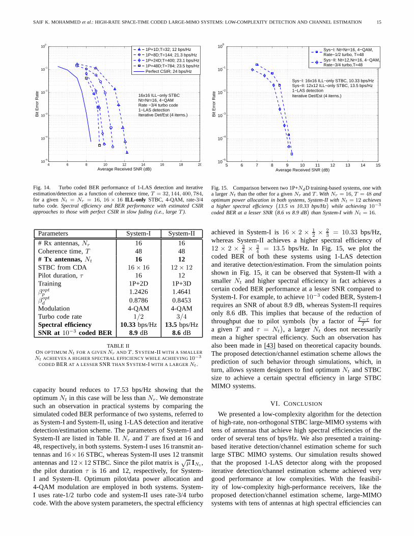
SAIF K. MOHAMMED et al.: HIGH-RATE SPACE-TIME CODED LARGE-MIMO SYSTEMS: LOW-COMPLEXITY DETECTION AND CHANNEL ESTIMATION 15
4 6 8 10 12 14 16 18 2010
−5
10−4
10−3
10−2
10−1
100
Average Received SNR (dB)
Bit
Err
or R
ate
1P+1D;T=32; 12 bps/Hz1P+8D;T=144; 21.3 bps/Hz1P+24D;T=400; 23.1 bps/Hz1P+48D;T=784; 23.5 bps/HzPerfect CSIR; 24 bps/Hz
16x16 ILL−only STBCNt=Nr=16, 4−QAMRate −3/4 turbo code1−LAS detectionIterative Det/Est (4 iterns.)
Fig. 14. Turbo coded BER performance of 1-LAS detection and iterativeestimation/detection as a function of coherence time,T = 32, 144, 400, 784,for a given Nt = Nr = 16, 16 × 16 ILL-only STBC, 4-QAM, rate-3/4turbo code.Spectral efficiency and BER performance with estimated CSIRapproaches to those with perfect CSIR in slow fading (i.e., large T ).
Parameters System-I System-II
# Rx antennas,Nr 16 16Coherence time,T 48 48# Tx antennas,Nt 16 12STBC from CDA 16 × 16 12 × 12Pilot duration,τ 16 12Training 1P+2D 1P+3Dβopt
p 1.2426 1.4641βopt
d 0.8786 0.8453Modulation 4-QAM 4-QAMTurbo code rate 1/2 3/4Spectral efficiency 10.33bps/Hz 13.5bps/HzSNR at 10−3 coded BER 8.9 dB 8.6 dB
TABLE IION OPTIMUM Nt FOR A GIVEN Nr AND T . SYSTEM-II WITH A SMALLER
Nt ACHIEVES A HIGHER SPECTRAL EFFICIENCY WHILE ACHIEVING10−3
CODED BER AT A LESSERSNRTHAN SYSTEM-I WITH A LARGER Nt .
capacity bound reduces to 17.53 bps/Hz showing that theoptimumNt in this case will be less thanNr. We demonstratesuch an observation in practical systems by comparing thesimulated coded BER performance of two systems, referred toas System-I and System-II, using 1-LAS detection and iterativedetection/estimation scheme. The parameters of System-I andSystem-II are listed in Table II.Nr andT are fixed at 16 and48, respectively, in both systems. System-I uses 16 transmit an-tennas and16×16 STBC, whereas System-II uses 12 transmitantennas and12×12 STBC. Since the pilot matrix is
õ INt
,the pilot durationτ is 16 and 12, respectively, for System-I and System-II. Optimum pilot/data power allocation and4-QAM modulation are employed in both systems. System-I uses rate-1/2 turbo code and system-II uses rate-3/4 turbocode. With the above system parameters, the spectral efficiency
5 6 7 8 9 10 11 12 13 14 1510
−5
10−4
10−3
10−2
10−1
100
Average Received SNR (dB)
Bit
Err
or R
ate
Sys−I: Nt=Nr=16, 4−QAM,Rate−1/2 turbo, T=48Sys−II: Nt=12,Nr=16, 4−QAM,Rate−3/4 turbo,T=48
Sys−I: 16x16 ILL−only STBC, 10.33 bps/HzSys−II: 12x12 ILL−only STBC, 13.5 bps/Hz1−LAS detectionIterative Det/Est (4 iterns.)
Fig. 15. Comparison between two 1P+NdD training-based systems, one witha largerNt than the other for a givenNr andT . With Nr = 16, T = 48 andoptimum power allocation in both systems, System-II withNt = 12 achievesa higher spectral efficiency
`
13.5 vs 10.33 bps/Hz´
while achieving10−3
coded BER at a lesser SNR`
8.6 vs 8.9 dB´
than System-I withNt = 16.
achieved in System-I is16 × 2 × 12 × 2
3 = 10.33 bps/Hz,whereas System-II achieves a higher spectral efficiency of12 × 2 × 3
4 × 34 = 13.5 bps/Hz. In Fig. 15, we plot the
coded BER of both these systems using 1-LAS detectionand iterative detection/estimation. From the simulation pointsshown in Fig. 15, it can be observed that System-II with asmaller Nt and higher spectral efficiency in fact achieves acertain coded BER performance at a lesser SNR compared toSystem-I. For example, to achieve10−3 coded BER, System-Irequires an SNR of about 8.9 dB, whereas System-II requiresonly 8.6 dB. This implies that because of the reduction ofthroughput due to pilot symbols
(by a factor of T−τ
Tfor
a given T and τ = Nt
), a largerNt does not necessarily
mean a higher spectral efficiency. Such an observation hasalso been made in [43] based on theoretical capacity bounds.The proposed detection/channel estimation scheme allows theprediction of such behavior through simulations, which, inturn, allows system designers to find optimumNt and STBCsize to achieve a certain spectral efficiency in large STBCMIMO systems.
VI. CONCLUSION
We presented a low-complexity algorithm for the detectionof high-rate, non-orthogonal STBC large-MIMO systems withtens of antennas that achieve high spectral efficiencies of theorder of several tens of bps/Hz. We also presented a training-based iterative detection/channel estimation scheme for suchlarge STBC MIMO systems. Our simulation results showedthat the proposed 1-LAS detector along with the proposediterative detection/channel estimation scheme achieved verygood performance at low complexities. With the feasibil-ity of low-complexity high-performance receivers, like theproposed detection/channel estimation scheme, large-MIMOsystems with tens of antennas at high spectral efficiencies can
16 ACCEPTED IN IEEE JOURNAL OF SELECTED TOPICS IN SIGNAL PROCESSING: SPL. ISS. ON MANAGING COMPLEXITY IN MULTIUSER MIMO SYSTEMS
become practical, enabling interesting high data rate wirelessapplications (e.g., wireless IPTV/HDTV distribution). Thiscan motivate the inclusion of large-MIMO architectures (e.g.,12×12, 16×16 MIMO systems, including those using STBCsfrom CDA) into wireless standards like IEEE 802.11n/VHTand IEEE 802.16/LTE-A in their evolution to achieve highdata rates at increased spectral efficiencies.
APPENDIX
Theorem 1: The l(k)p in (21) minimizesF(l
(k)p ) in (19) and
this minimum value is non-positive.
Proof: Let r△=
⌊|z(k)
p |2ap
⌋. Then
|z(k)p |
2ap= r+f , where0 ≤ f < 1,
and so we can write
|z(k)p |ap
= 2r + 2f. (48)
If l(k)p were unconstrained to be any real number, then the
optimal value of l(k)p is
|z(k)p |ap
, which would lie between
2r and 2r + 2 (as per (48)). SinceF(l(k)p ) is quadratic in
l(k)p , it is unimodular, and hence the optimal point (withl
(k)p
constrained) would be either2r or 2r+2. Using (19) and (48),we can evaluateF(2r + 2) −F(2r) to be
F(2r + 2) −F(2r) = 4ap(1 − 2f). (49)
Sinceap is a positive quantity, the sign ofF(2r+2)−F(2r)depends upon the sign of(1 − 2f). If f ≥ 0.5, thenF(2r +2) ≤ F(2r), and therefore2r + 2 is the optimal value ofl(k)p . Similarly, whenf < 0.5, 2r is the optimal value ofl(k)
p .Therefore, it follows that indeed the rounding solution givenby (21) is optimal.F(l
(k)p ) is non-positive for all values of
l(k)p between zero and
2|z(k)p |
ap. If f < 0.5, then2r is optimal,
and, from (48), we know that2r ≤ |z(k)p |ap
, and therefore2r <
2|z(k)
p |ap
. HenceF (2r) = F (opt) is non-positive. Similarly, iff ≥ 0.5, then 2r + 2 is optimal, andF(2r + 2) ≤ F(2r).
However, since2r is always less than2|z(k)
p |ap
, F(2r) is non-
positive and thereforeF(2r + 2) = F (opt) is non-positive.
ACKNOWLEDGMENT
We would like to thank the Editor, Prof. R. Calderbank,for handling the review process. We would like to thank theanonymous reviewers for their critical and useful comments,and for motivating us to compare the performance and com-plexity of the proposed scheme with those of other large-MIMO architectures/detectors.
REFERENCES
[1] I. E. Telatar, “Capacity of multi-antenna Gaussian channels,” EuropeanTrans. Telecommun.,vol. 10, no. 6, pp. 585-595, November 1999.
[2] A. Paulraj, R. Nabar, and D. Gore,Introduction to Space-Time WirelessCommunications, Cambridge University Press, 2003.
[3] H. Jafarkhani, Space-Time Coding: Theory and Practice, CambridgeUniversity Press, 2005.
[4] http://www.ruckuswireless.com/technology/beamflex.php[5] S. M. Alamouti, “A simple transmit diversity technique for wireless
communications,”IEEE Jl. Sel. Areas in Commun.,vol. 16, no. 8, pp.1451–1458, October 1998.
[6] V. Tarokh, H. Jafarkhani, and A. R. Calderbank, “Space-time block codesfrom orthogonal designs,”IEEE Trans. Inf. Theory,vol. 45, no. 5, pp.1456-1467, July 1999.
[7] B. A. Sethuraman, B. Sundar Rajan, and V. Shashidhar, “Full-diversityhigh-rate space-time block codes from division algebras,”IEEE Trans.Inf. Theory, vol. 49, no. 10, pp. 2596-2616, October 2003.
[8] E. Viterbo and J. Boutros, “A universal lattice code decoder for fadingchannels,”IEEE Trans. Inform. Theory,vol. 45, no. 5, pp. 1639-1242,July 1999.
[9] M. O. Damen, H. El Gamal, and G. Caire, “On maximum-likelihooddetection and the search for the closest lattice point,”IEEE Trans. Inform.Theory, vol. 49, no. 10, pp. 2389-2401, October 2003.
[10] B. Hassibi and H. Vikalo, “On the sphere-decoding algorithm I. Ex-pected complexity,”IEEE Trans. Sig. Proc.,vol. 53, no. 8, pp. 2806-2818,August 2005.
[11] L. Azzam and E. Ayanoglu, “Reduced complexity sphere decoding forsquare QAM via a new lattice representation,” arXiv:0705.2435v1 [cs.IT]16 May 2007.
[12] X. Yang, Y. Xiong, and F. Wang, “An adaptive MIMO system based onunified belief propagation detection,”Proc. IEEE ICC’2007, June 2007.
[13] B. Farhang-Boroujeny, H. Zhu, and Z. Shi, “Markov chainMonte Carloalgorithms for CDMA and MIMO communication systems,”IEEE Trans.on Sig. Proc.,vol. 54, no. 5, pp. 1896-1908, May 2006.
[14] Y. Sun, “A family of linear complexity likelihood ascent search detectorsfor CDMA multiuser detection,”Proc. IEEE Intl. Symp. on SpreadSpectrum Tech. & App.,September 2000.
[15] K. Vishnu Vardhan, Saif K. Mohammed, A. Chockalingam, B. SundarRajan, “A low-complexity detector for large MIMO systems and multi-carrier CDMA systems,”IEEE JSAC Spl. Iss. on Multiuser Detection, forAdv. Commun. Syst. & Networks, vol. 26, no. 3, pp. 473-485, April 2008.
[16] Saif K. Mohammed, K. Vishnu Vardhan, A. Chockalingam, and B.Sundar Rajan, “Large MIMO systems: A low-complexity detector at highspectral efficiencies,”Proc. IEEE ICC’2008, May 2008.
[17] J.-C. Belfiore, G. Rekaya, and E. Viterbo, “The golden code: A 2 × 2full-rate space-time code with non-vanishing determinants,” IEEE Trans.Inform. Theory, vol. 51, no. 4, pp. 1432-1436, April 2005.
[18] P. Dayal and M. K. Varanasi, “An optimal two transmit antenna space-time code and its stacked extensions,”Proc. Asilomar Conf. on Signals,Systems and Computers, 2003.
[19] F. E. Oggier, G. Rekaya, J.-C. Belfiore, and E. Viterbo, “Perfect space-time block codes,”IEEE Trans. on Inform. Theory, vol. 52, no. 9, pp.3885-3902, September 2006.
[20] P. Elia, B. A. Sethuraman, and P. V. Kumar, “Perfect space-time codesfor any number of antennas,”IEEE Trans. Inform. Theory,vol. 53, no.11, pp. 3853-3868, November 2007.
[21] F. Oggier, J.-C. Belfiore, and E. Viterbo,Cyclic Division Algebras: ATool for Space-Time Coding,Foundations and Trends in Commun. andInform. Theory, vol. 4, no. 1, pp. 1-95, Now Publishers, 2007.
[22] J. Kazemitabar and H. Jafarkhani, “Multiuser interference cancellationand detection for users with more than two transmit antennas,” IEEETrans. on Commun.,vol. 56, no. 4, pp. 574-583, April 2008.
[23] D. Gesbert, H. Bolcskei, D. A. Gore, and A. J. Paulraj, “Outdoor MIMOwireless channels: Models and performance prediction,”IEEE Trans. onCommun.,vol. 50, no. 12, pp. 1926-1934, December 2002.
[24] G. H. Golub and C. F. Vanloan,Matrix Computations, 2nd Ed., JohnsHopkins University Press, Baltimore, 1989.
[25] S. Verdu,Multiuser Detection,Cambridge University Press, 1998.[26] Saif K. Mohammed, A. Chockalingam, and B. Sundar Rajan,“High-
rate space-time coded large MIMO systems: Low-complexity detectionand performance,”IEEE GLOBECOM’2008, November-December 2008.
[27] B. Hassibi and B. Hochwald, “High rate codes that are linear in spaceand time,” IEEE Trans. Inf. Theory, vol. 48, pp. 1804-1824, July 2002.
[28] Saif K. Mohammed, A. Chockalingam, and B. Sundar Rajan,“A low-complexity near-ML performance achieving algorithm for large MIMOdetection,”Proc. IEEE ISIT’2008, July 2008.
[29] Saif K. Mohammed, A. Chockalingam, and B. Sundar Rajan,“Asymp-totic analysis of the performance of LAS algorithm for largeMIMOdetection,” Online arXiv:0806.2533v1 [cs.IT], 16 June 2008.
[30] W. J. Choi, K. W. Cheong, and J. M. Cioffi, “Iterative softinterferencecancellation for multiple antenna systems,”Proc. IEEE WCNC’2000, vol.1, pp. 304-309, September 2000.
[31] N. Prasad, M. K. Varanasi, L. Venturino, X. Wang, “An analysis of theMIMO-SDMA channel with space-time orthogonal and quasi-orthogonaluser transmissions and efficient successive cancellation decoders,”IEEETrans. Inf. Theory, vol. 54, no. 12, pp. 5427-5446, December 2008.
[32] C. W. Tan and A. R. Calderbank, “Multiuser detection of Alamoutisignals,” to appear in IEEE Trans. on Commun.,2009.
SAIF K. MOHAMMED et al.: HIGH-RATE SPACE-TIME CODED LARGE-MIMO SYSTEMS: LOW-COMPLEXITY DETECTION AND CHANNEL ESTIMATION 17
[33] D. Shiu, G. J. Foschini, M. J. Gans, and J. M. Khan, “Fading correlationand its effect on the capacity of multi-antenna systems,”IEEE Trans.Commun.,vol. 48, pp. 502-513, March 2000.
[34] Saif K. Mohammed, A. Chockalingam, and B. Sundar Rajan,“Low-complexity detection and performance in multi-gigabit high spectralefficiency large MIMO systems,”IEEE PIMRC’2008, September 2008.
[35] M. Vu, and A. Paulraj, “Optimal linear precoders for MIMO wirelesscorrelated channels with nonzero mean in spacetime coded systems,”IEEE Trans. Sig. Proc.,vol. 54, no. 6, pp. 2318-2332, June 2006.
[36] H. R. Bahrami and T. Le-Ngoc, “Precoder design based on correlationmatrices for MIMO systems,”IEEE Trans. Wireless Commun., vol. 5, no.12, pp. 3579-3587, December 2006.
[37] K. T. Phan, S. A. Vorobyov, and C. Tellambura, “Precoderdesign forspace-time coded systems with correlated Rayleigh fading channels usingconvex optimization,”IEEE Trans. Sig. Proc.,vol. 57, no. 2, pp. 814-819,February 2009.
[38] A. Zaki, Saif K. Mohammed, A. Chockalingam, and S. Sundar Rajan,“A training-based iterative detection/channel estimation scheme for largenon-orthogonal STBC MIMO systems,”IEEE ICC’2009, June 2009.
[39] M. Brehler and M. K. Varanasi, “Training-codes for non-coherent multi-antenna block-Rayleigh fading channel,”Proc. CISS’2003, March 2003.
[40] H. El Gamal and M. O. Damen, “Universal space-time coding,” IEEETrans. Inf. Theory, vol. 49, no. 5, pp. 1097-1119, May 2003.
[41] H. El Gamal, H. Aktas, and M. O. Damen, “Coherent space-time codesfor noncoherent channels,”Proc. IEEE GLOBECOM’2003, pp. 1915-1918, December 2003.
[42] J.-C. Belfiore and A. M. Cipriano, “Space-time coding for noncoherentchannels,” Book Chapter inSpace-Time Wireless Systems: From ArrayProcessing to MIMO Communications, Edited by H. Bolcskei,D. Gesbert,C. B. Papadias, and A.-J. van der Veen,Cambridge Univ. Press, 2006.
[43] B. Hassibi and B. M. Hochwald, “How much training is needed inmultiple-antenna wireless links?”IEEE Trans. Inform. Theory,vol. 49,no. 4, pp. 951-963, April 2003.
[44] P. Stoica and G. Ganesan, “Space-time block codes: trained, blind andsemi-blind detection,”Proc. IEEE ICASSP’2002, pp. 1609-1612, 2002.
[45] A. Lampe, “Iterative multiuser detection with integrated channel esti-mation for coded DS-CDMA,”IEEE Trans. Commun., vol. 50, no. 8, pp.1217-1223, August 2002.
[46] H. Li, S. M. Betz, and H. V. Poor, “Performance analysis of iterativechannel estimation and multiuser detection in multipath DS-CDMAchannels,”IEEE Trans. Sig. Proc.,vol. 55, pp. 1981-1993, May 2007.
[47] B. Hu, I. Land, L. Rasmussen, R. Piton, and B. H. Fleury, “A divergenceminimization approach to joint multiuser decoding for coded CDMA,”IEEE Jl. on Sel. Areas in Commun.,vol. 26, pp. 432-445, April 2008.
[48] M. Loncar, R. R. Muller, J. Wehinger, C. F. Mecklenbrauker, and T. Abe,“Iterative channel estimation and data detection in frequency-selectivefading MIMO channels,”Eur. Trans. Telecommun., vol. 15, no. 5, pp.459-470, September/October 2004.
[49] H. Zhu, B. Farhang-Boroujeny, and C. Schlegel, “Pilot embedding forjoint channel estimation and data detection in MIMO communicationsystems,”IEEE Commun. Letters, vol. 7, no. 1, pp. 30-32, January 2003.
[50] J. Akhtman and L. Hanzo, “Iterative receiver architectures for MIMO-OFDM,” Proc. IEEE WCNC’2007, pp. 825-829, March 2007.
[51] P. S. Rossi and R. R. Muller, “Joint twofold-iterative channel estima-tion and multiuser detection for MIMO-OFDM systems,”IEEE Trans.Wireless Commun.,vol. 7, no. 11, pp. 4719-4729, November 2008.
[52] V. Shashidhar, B. Sundar Rajan, and B. A. Sethuraman, “Information-lossless space-time block codes from crossed-product algebras,” IEEETrans. Inform. Theory, vol. 52, no. 9, pp. 3913-3935, September 2006.
PLACEPHOTOHERE
Saif K. Mohammed received his B.Tech degree inComputer Science and Engineering from the IndianInstitute of Technology, New Delhi, India, in 1998.From 1998 to 2000, he was employed with PhilipsInc., Bangalore, as an ASIC design engineer. From2000 to 2003, he worked with Ishoni NetworksInc., Santa Clara, CA, as a senior chip architectureengineer. From 2003 to 2007, he was employedwith Texas Instruments, Bangalore as systems andalgorithms designer in the wireless systems group.Since 2006, he is pursuing his doctoral degree in
Electrical and Communications Engineering at the Indian Institute of Science,Bangalore, India. His research interests include low-complexity detection,estimation and coding for wireless communications systems.
PLACEPHOTOHERE
Ahmed Zaki received the B.E. degree in Electron-ics and Communication Engineering from OsmaniaUniversity, Hyderabad, India, in 2007, and the M.E.degree in Telecommunication from the Indian In-stitute of Science, Bangalore, India, in 2009. Hisresearch interest lies in the area of wireless com-munications, including receiver design and channelestimation for large-MIMO systems, MIMO-OFDM,multiuser communications, and algorithm design.
PLACEPHOTOHERE
A. Chockalingam was born in Rajapalayam, TamilNadu, India. He received the B.E. (Honors) degreein Electronics and Communication Engineering fromthe P. S. G. College of Technology, Coimbatore,India, in 1984, the M.Tech degree with specializationin satellite communications from the Indian Instituteof Technology, Kharagpur, India, in 1985, and thePh.D. degree in Electrical Communication Engineer-ing (ECE) from the Indian Institute of Science (IISc),Bangalore, India, in 1993. During 1986 to 1993, heworked with the Transmission R & D division of the
Indian Telephone Industries Limited, Bangalore. From December 1993 to May1996, he was a Postdoctoral Fellow and an Assistant Project Scientist at theDepartment of Electrical and Computer Engineering, University of California,San Diego. From May 1996 to December 1998, he served Qualcomm, Inc.,San Diego, CA, as a Staff Engineer/Manager in the systems engineering group.In December 1998, he joined the faculty of the Department of ECE, IISc,Bangalore, India, where he is a Professor, working in the area of wirelesscommunications and networking.
Dr. Chockalingam is a recipient of the Swarnajayanti Fellowship from theDepartment of Science and Technology, Government of India.He served as anAssociate Editor of the IEEE Transactions on Vehicular Technology from May2003 to April 2007. He currently serves as an Editor of the IEEE Transactionson Wireless Communications. He served as a Guest Editor for the IEEEJSAC Special Issue on Multiuser Detection for Advanced CommunicationSystems and Networks. He is a Fellow of the Institution of Electronics andTelecommunication Engineers, and a Fellow of the Indian National Academyof Engineering.
PLACEPHOTOHERE
B. Sundar Rajan (S’84-M’91-SM’98) was born inTamil Nadu, India. He received the B.Sc. degreein mathematics from Madras University, Madras,India, the B.Tech degree in electronics from MadrasInstitute of Technology, Madras, and the M.Techand Ph.D. degrees in electrical engineering fromthe Indian Institute of Technology, Kanpur, India,in 1979, 1982, 1984, and 1989 respectively. He wasa faculty member with the Department of ElectricalEngineering at the Indian Institute of Technology inDelhi, India, from 1990 to 1997. Since 1998, he has
been a Professor in the Department of Electrical Communication Engineeringat the Indian Institute of Science, Bangalore, India. His primary researchinterests include space-time coding for MIMO channels, distributed space-time coding and cooperative communication, coding for multiple-access, relaychannels and network coding with emphasis on algebraic techniques.
Dr. Rajan is an Associate Editor of the IEEE Transactions on InformationTheory, an Editor of the IEEE Transactions on Wireless Communications, andan Editorial Board Member of International Journal of Information and CodingTheory. He served as Technical Program Co-Chair of the IEEE InformationTheory Workshop (ITW’02), held in Bangalore, in 2002. He is aFellow ofIndian National Academy of Engineering and recipient of theIETE PuneCenter’s S.V.C Aiya Award for Telecom Education in 2004. Also, Dr. Rajanis a Member of the American Mathematical Society.
Related Documents