HIGH PRESSURE FORGED STEEL VALVES ILSHIN VALVE CO., LTD. C-16 Rev. 2

Welcome message from author
This document is posted to help you gain knowledge. Please leave a comment to let me know what you think about it! Share it to your friends and learn new things together.
Transcript
HIGH PRESSUREFORGED STEEL VALVES
ILSHIN VALVE CO., LTD.
C-16Rev. 2
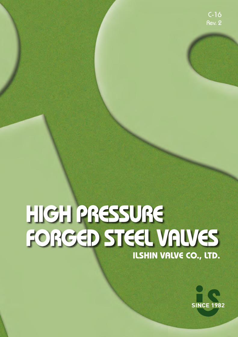
ESTABLISHMENTIlshin Valve Company Limited was incoporated in Bucheon City near by Seoul on July, 1982.
KEY INFORMATIONSOwnership : Mr. Hyeon Jo, Kim / PresidentQuality Certificate· ISO 9001 (HSB AP 1343)· ISO 14001 (HSBRSK-E160)· ISO 18001 (HSB AP-S1428)· PED 97/23/EC (HSBI-11-03-006)· API 6D (6D-1194)· KEPIC (Q-Class Nuclear Product)· ASME N, NPT (N-3279, N-3280)
HEAD OFFICE & FACTORYAddress : 1 Na 703, Sihwa Industrial Complex, 1244-2, Jeongwang-Dong, Siheung-Si, Gyeonggi-Do, Zip code 429-912, KOREATelephone : +82-31-433-8176|Facsmile : +82-31-433-8178|E-mail : [email protected]
PRODUCTS INDEXMOTOR OPERATED VALVESSEAL WELDED BONNET TYPE GATE VALVESSEAL WELDED BONNET TYPE GLOBE VALVESSEAL WELDED BONNET TYPE Y-GLOBE VALVESSEAL WELDED BONNET TYPE LIFT CHECK VALVESPRESSURE SEAL BONNET TYPE GLOBE VALVESVALVE FLOW CAPACITY EVALUATIONPRESSURE-TEMP. RATING CHARTSTANDARD MATERIALSTRIM MATERIALSSPECIFICATIONS OF FORGED&CAST VALVE MATERIALSTHREAD & SOCKET DIMENSION
12-34-56-78-9
10-1112-1314-15
1616-18
1819
20-21
INDEX
To be the most competitive edge designer and manufacturer over the world.Satisfy customers with best quality, delivery and price.
2 ILSHIN _ Forged Steel Valves 3www.ilshin.com _ ILSHIN
HIGH PRESSURE VALVES
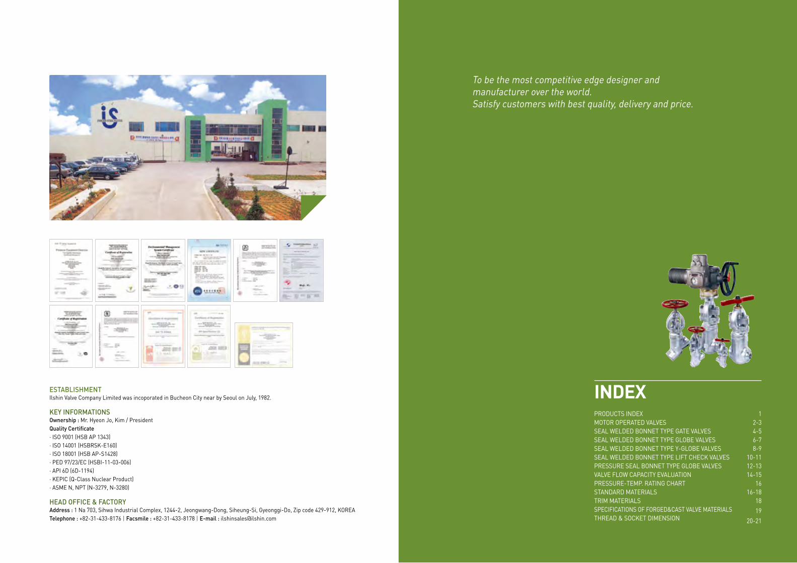
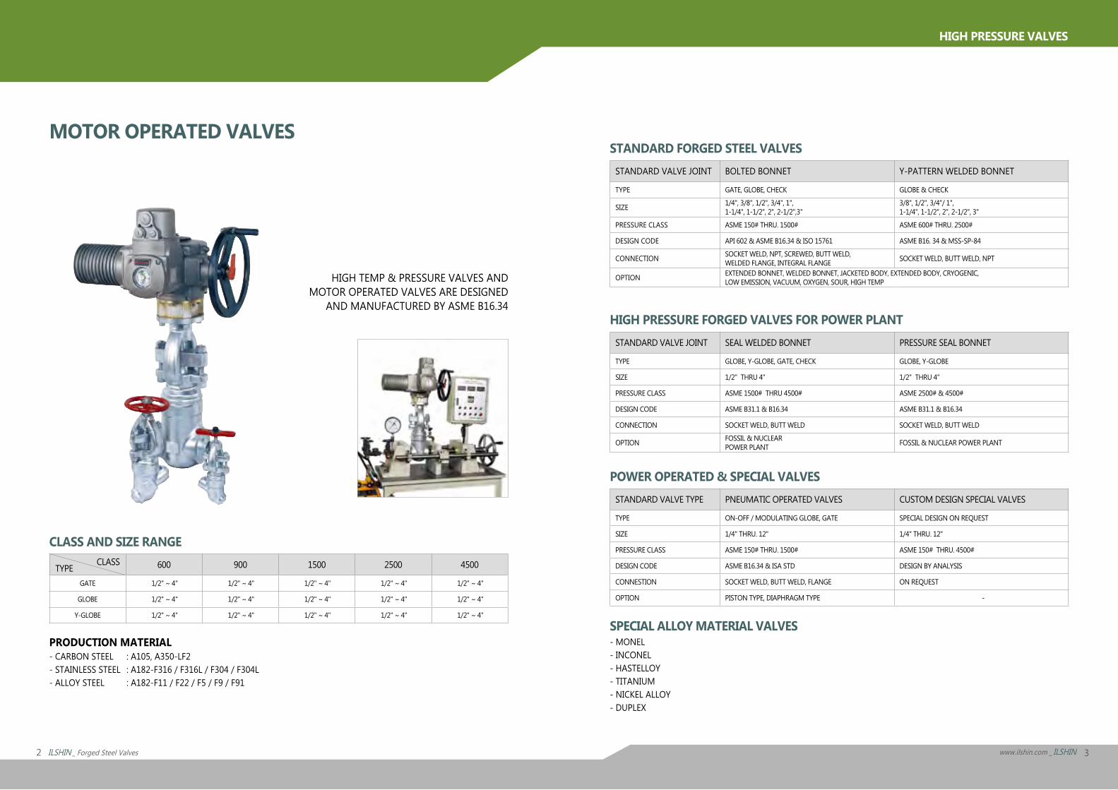
HIGH TEMP & PRESSURE VALVES ANDMOTOR OPERATED VALVES ARE DESIGNED
AND MANUFACTURED BY ASME B16.34
PRODUCTION MATERIAL- CARBON STEEL : A105, A350-LF2- STAINLESS STEEL : A182-F316 / F316L / F304 / F304L- ALLOY STEEL : A182-F11 / F22 / F5 / F9 / F91
SPECIAL ALLOY MATERIAL VALVES- MONEL- INCONEL- HASTELLOY- TITANIUM- NICKEL ALLOY- DUPLEX
CLASS AND SIZE RANGE
TYPE CLASS 600 900 1500 2500 4500
GATE 1/2" ~ 4" 1/2" ~ 4" 1/2" ~ 4" 1/2" ~ 4" 1/2" ~ 4"
GLOBE 1/2" ~ 4" 1/2" ~ 4" 1/2" ~ 4" 1/2" ~ 4" 1/2" ~ 4"
Y-GLOBE 1/2" ~ 4" 1/2" ~ 4" 1/2" ~ 4" 1/2" ~ 4" 1/2" ~ 4"
STANDARD FORGED STEEL VALVESSTANDARD VALVE JOINT BOLTED BONNET Y-PATTERN WELDED BONNET
TYPE GATE, GLOBE, CHECK GLOBE & CHECK
SIZE 1/4", 3/8", 1/2", 3/4", 1",1-1/4", 1-1/2", 2", 2-1/2",3"
3/8", 1/2", 3/4"/ 1",1-1/4", 1-1/2", 2", 2-1/2", 3"
PRESSURE CLASS ASME 150# THRU. 1500# ASME 600# THRU. 2500#
DESIGN CODE API 602 & ASME B16.34 & ISO 15761 ASME B16. 34 & MSS-SP-84
CONNECTION SOCKET WELD, NPT, SCREWED, BUTT WELD,WELDED FLANGE, INTEGRAL FLANGE SOCKET WELD, BUTT WELD, NPT
OPTION EXTENDED BONNET, WELDED BONNET, JACKETED BODY, EXTENDED BODY, CRYOGENIC, LOW EMISSION, VACUUM, OXYGEN, SOUR, HIGH TEMP
HIGH PRESSURE FORGED VALVES FOR POWER PLANTSTANDARD VALVE JOINT SEAL WELDED BONNET PRESSURE SEAL BONNET
TYPE GLOBE, Y-GLOBE, GATE, CHECK GLOBE, Y-GLOBE
SIZE 1/2" THRU 4" 1/2" THRU 4"
PRESSURE CLASS ASME 1500# THRU 4500# ASME 2500# & 4500#
DESIGN CODE ASME B31.1 & B16.34 ASME B31.1 & B16.34
CONNECTION SOCKET WELD, BUTT WELD SOCKET WELD, BUTT WELD
OPTION FOSSIL & NUCLEARPOWER PLANT FOSSIL & NUCLEAR POWER PLANT
POWER OPERATED & SPECIAL VALVESSTANDARD VALVE TYPE PNEUMATIC OPERATED VALVES CUSTOM DESIGN SPECIAL VALVES
TYPE ON-OFF / MODULATING GLOBE, GATE SPECIAL DESIGN ON REQUEST
SIZE 1/4" THRU. 12" 1/4" THRU. 12"
PRESSURE CLASS ASME 150# THRU. 1500# ASME 150# THRU. 4500#
DESIGN CODE ASME B16.34 & ISA STD DESIGN BY ANALYSIS
CONNESTION SOCKET WELD, BUTT WELD, FLANGE ON REQUEST
OPTION PISTON TYPE, DIAPHRAGM TYPE -
MOTOR OPERATED VALVES
4 ILSHIN _ Forged Steel Valves 5www.ilshin.com _ ILSHIN
HIGH PRESSURE VALVES
PART NO PART ASTM SPEC A105 A182
F11 F22 F91 F304 F316 F511 BODY A105N A182-F11 A182-F22 A182-F91 A182-F304
A182-F304LA182-F316 A182-F316L A182-F51
2 SEATRING A276-410+STL A276-316+STL A276-304+STL A276-316+STL UNS S31803
+STL
3 WEDGE A276-410+STL A276-316+STL A276-304+STL A276-316+STL UNS S31803
+STL
4 STEM A276-410 A276-316 A276-304+STL A276-316+STL UNS S31803
+STL
5 BONNET A105N A182-F11 A182-F22 A182-F91 A182-F304 A182-F304L
A182-F316 A182-F316L A182-F51
6 GLANG PACKING Flexible Graphite
7 YOKE A105N A182-F304
8 GLAND 304SS
9 GLANG FLANGE A105 304SS
10 GLAND NUT A194-8
11 GLAND BOLT A193-B8
12 STEM NUT High Tension Brass
13 THRUST WASHER High Tension Brass
14 HANDWHEEL A197
15 NAME PLATE Aluminum Stainless Steel
16 HANDWHEEL NUT Cabon Steel
17 PACKING WASHER 316SS
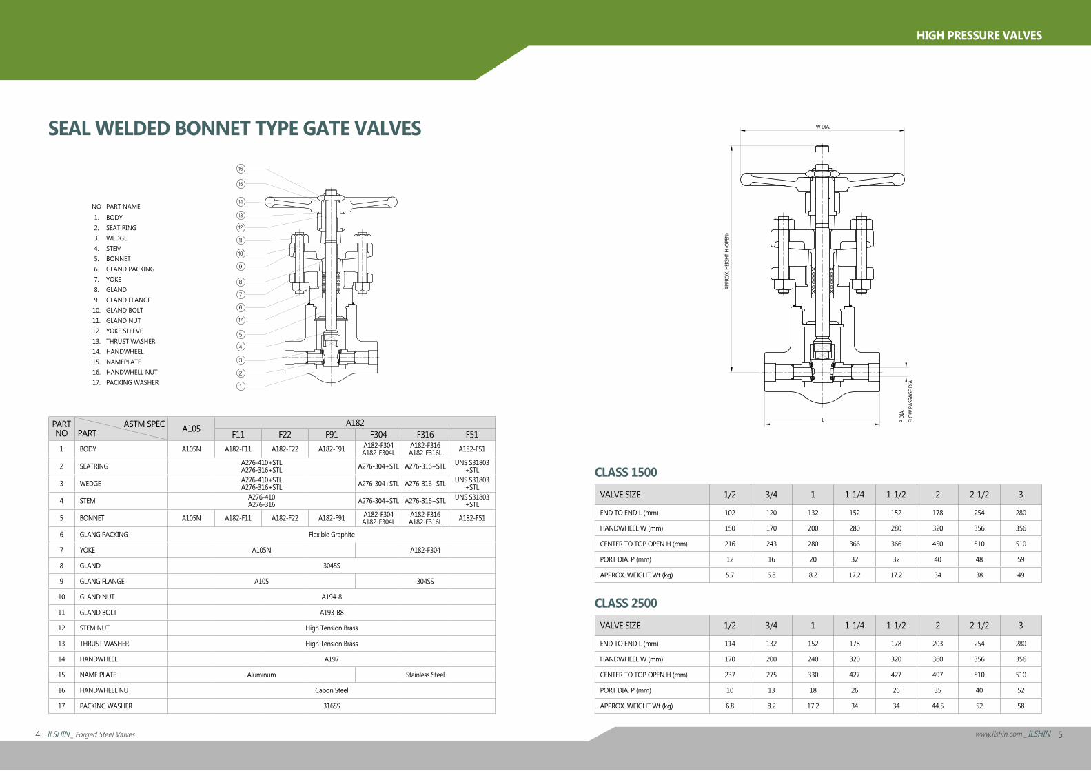
CLASS 1500VALVE SIZE 1/2 3/4 1 1-1/4 1-1/2 2 2-1/2 3
END TO END L (mm) 102 120 132 152 152 178 254 280
HANDWHEEL W (mm) 150 170 200 280 280 320 356 356
CENTER TO TOP OPEN H (mm) 216 243 280 366 366 450 510 510
PORT DIA. P (mm) 12 16 20 32 32 40 48 59
APPROX. WEIGHT Wt (kg) 5.7 6.8 8.2 17.2 17.2 34 38 49
CLASS 2500VALVE SIZE 1/2 3/4 1 1-1/4 1-1/2 2 2-1/2 3
END TO END L (mm) 114 132 152 178 178 203 254 280
HANDWHEEL W (mm) 170 200 240 320 320 360 356 356
CENTER TO TOP OPEN H (mm) 237 275 330 427 427 497 510 510
PORT DIA. P (mm) 10 13 18 26 26 35 40 52
APPROX. WEIGHT Wt (kg) 6.8 8.2 17.2 34 34 44.5 52 58
NO1.2.3.4.5.6.7.8.9.10.11.12.13.14.15.16.17.
PART NAMEBODYSEAT RINGWEDGESTEMBONNETGLAND PACKINGYOKEGLANDGLAND FLANGEGLAND BOLTGLAND NUTYOKE SLEEVETHRUST WASHERHANDWHEELNAMEPLATEHANDWHELL NUTPACKING WASHER
SEAL WELDED BONNET TYPE GATE VALVES
P DI
A.
W DIA.
L
APPR
OX. H
EIGHT
H (O
PEN)
FLOW
PAS
SAGE
DIA
.
16
15
14
13
12
11
10
9
8
7
6
17
5
4
3
2
1
6 ILSHIN _ Forged Steel Valves 7www.ilshin.com _ ILSHIN
HIGH PRESSURE VALVES
PART NO PART ASTM SPE A105 A182
F11 F22 F91 F304 F316 F511 BODY A105N A182-F11 A182-F22 A182-F91 A182-F304
A182-F304LA182-F316 A182-F316L A182-F51
2 SEAT SURFACE Stellite on Body
3 DISC PAD A276-420
4 DISC A276-410+STL A276-316+STL A276-304+STL A276-316+STL UNS S31803+STL
5 STEM A276-410 A276-316 A276-304+STL A276-316+STL UNS S31803+STL
6 BONNET A105N A182-F11 A182-F22 A182-F91 A182-F304 A182-F304L
A182-F316 A182-F316L A182-F51
7 GLAND PACKING Flexible Graphite
8 YOKE A105N A182-F304
9 GLAND 304SS
10 GLAND FLANGE A105 304SS
11 GLAND NUT A194-8
12 GLAND BOLT A193-B8
13 YOKE BUSH High Tension Brass
14 HANDWHEEL A197
15 NAMEPLATE Aluminum Stainless Steel
16 HANDWHEEL WASHER Stainless Steel
17 HANDWHEEL NUT Cabon Steel
18 PACKING WASHER 316SS
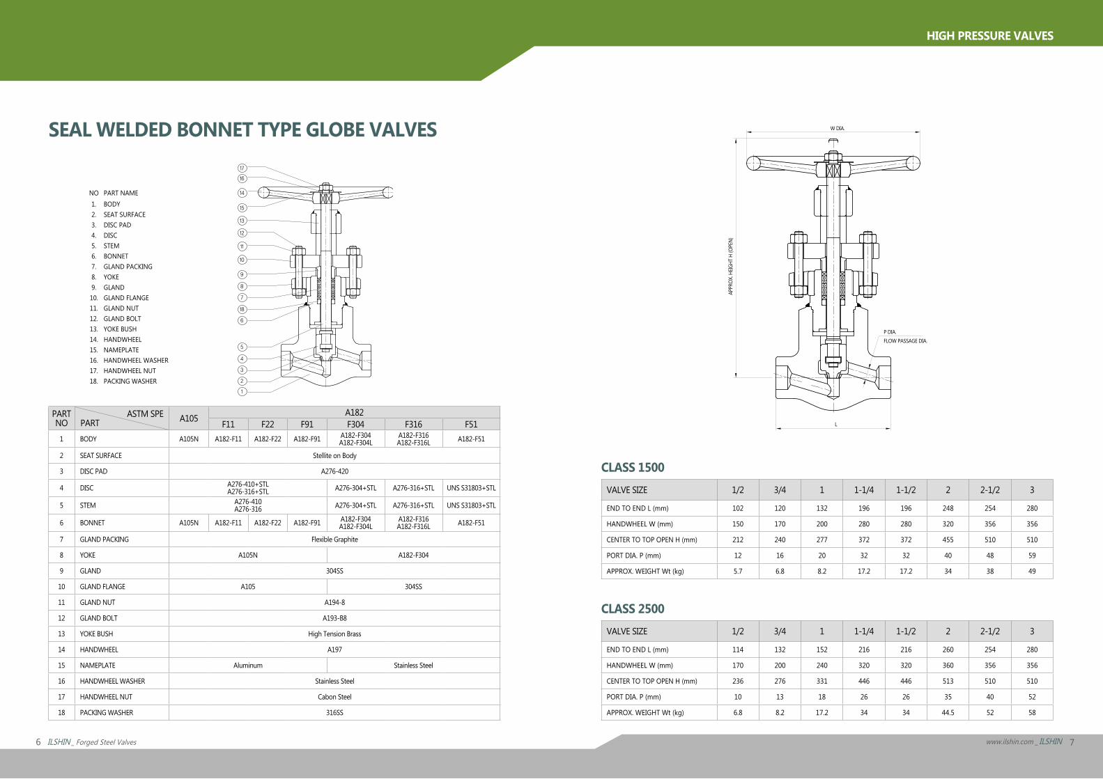
CLASS 1500VALVE SIZE 1/2 3/4 1 1-1/4 1-1/2 2 2-1/2 3
END TO END L (mm) 102 120 132 196 196 248 254 280
HANDWHEEL W (mm) 150 170 200 280 280 320 356 356
CENTER TO TOP OPEN H (mm) 212 240 277 372 372 455 510 510
PORT DIA. P (mm) 12 16 20 32 32 40 48 59
APPROX. WEIGHT Wt (kg) 5.7 6.8 8.2 17.2 17.2 34 38 49
CLASS 2500VALVE SIZE 1/2 3/4 1 1-1/4 1-1/2 2 2-1/2 3
END TO END L (mm) 114 132 152 216 216 260 254 280
HANDWHEEL W (mm) 170 200 240 320 320 360 356 356
CENTER TO TOP OPEN H (mm) 236 276 331 446 446 513 510 510
PORT DIA. P (mm) 10 13 18 26 26 35 40 52
APPROX. WEIGHT Wt (kg) 6.8 8.2 17.2 34 34 44.5 52 58
NO1.2.3.4.5.6.7.8.9.10.11.12.13.14.15.16.17.18.
PART NAMEBODYSEAT SURFACEDISC PADDISCSTEMBONNETGLAND PACKINGYOKEGLANDGLAND FLANGEGLAND NUTGLAND BOLTYOKE BUSHHANDWHEELNAMEPLATEHANDWHEEL WASHERHANDWHEEL NUTPACKING WASHER
SEAL WELDED BONNET TYPE GLOBE VALVES
10
9
8
7
18
6
5
4
3
1
2
11
12
13
15
14
16
17
APPR
OX. H
EIGHT
H (O
PEN)
P DIA.
W DIA.
L
FLOW PASSAGE DIA.
8 ILSHIN _ Forged Steel Valves 9www.ilshin.com _ ILSHIN
HIGH PRESSURE VALVES
PART NO PART ASTM SPE A105 A182
F11 F22 F91 F304 F316 F511 BODY A105N A182-F11 A182-F22 A182-F91 A182-F304
A182-F304LA182-F316 A182-F316L A182-F51
2 SEAT SURFACE Stellite on Body
3 DISC PAD A276-420
4 DISC A276-410+STL A276-316+STL A276-304+STL A276-316+STL UNS S31803+STL
5 STEM A276-410 A276-316 A276-304+STL A276-316+STL UNS S31803+STL
6 BONNET A105N A182-F11 A182-F22 A182-F91 A182-F304 A182-F304L
A182-F316 A182-F316L A182-F51
7 GLAND PACKING Flexible Graphite
8 YOKE A105N A182-F304
9 GLAND 304SS
10 GLAND FLANGE A105 304SS
11 GLAND NUT A194-8
12 GLAND BOLT A193-B8
13 YOKE BUSH High Tension Brass
14 HANDWHEEL A197
15 NAMEPLATE Aluminum Stainless Steel
16 HANDWHEEL WASHER Stainless Steel
17 HANDWHEEL NUT Cabon Steel
18 PACKING WASHER 316SS
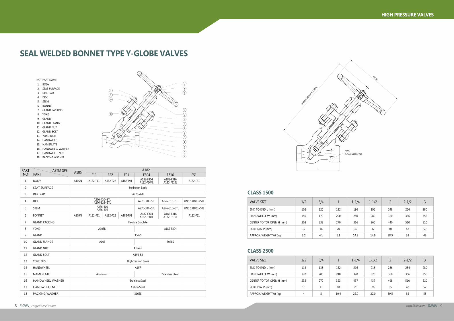
CLASS 1500VALVE SIZE 1/2 3/4 1 1-1/4 1-1/2 2 2-1/2 3
END TO END L (mm) 102 120 132 196 196 248 254 280
HANDWHEEL W (mm) 150 170 200 280 280 320 356 356
CENTER TO TOP OPEN H (mm) 208 233 270 366 366 440 510 510
PORT DIA. P (mm) 12 16 20 32 32 40 48 59
APPROX. WEIGHT Wt (kg) 3.2 4.1 6.1 14.9 14.9 28.5 38 49
CLASS 2500VALVE SIZE 1/2 3/4 1 1-1/4 1-1/2 2 2-1/2 3
END TO END L (mm) 114 135 152 216 216 286 254 280
HANDWHEEL W (mm) 170 200 240 320 320 360 356 356
CENTER TO TOP OPEN H (mm) 232 270 323 437 437 498 510 510
PORT DIA. P (mm) 10 13 18 26 26 35 40 52
APPROX. WEIGHT Wt (kg) 4 5 10.4 22.0 22.0 39.5 52 58
SEAL WELDED BONNET TYPE Y-GLOBE VALVES
NO1.2.3.4.5.6.7.8.9.10.11.12.13.14.15.16.17.18.
PART NAMEBODYSEAT SURFACEDISC PADDISCSTEMBONNETGLAND PACKINGYOKEGLANDGLAND FLANGEGLAND NUTGLAND BOLTYOKE BUSHHANDWHEELNAMEPLATEHANDWHEEL WASHERHANDWHEEL NUTPACKING WASHER
APPR
OX. HEIG
HT H (O
PEN)
P DIA.
W DIA.
L
FLOW PASSAGE DIA.
10
18
11
12
17
14
13
9
7
8
6
5
4
3
2
1
16
15
10 ILSHIN _ Forged Steel Valves 11www.ilshin.com _ ILSHIN
HIGH PRESSURE VALVES
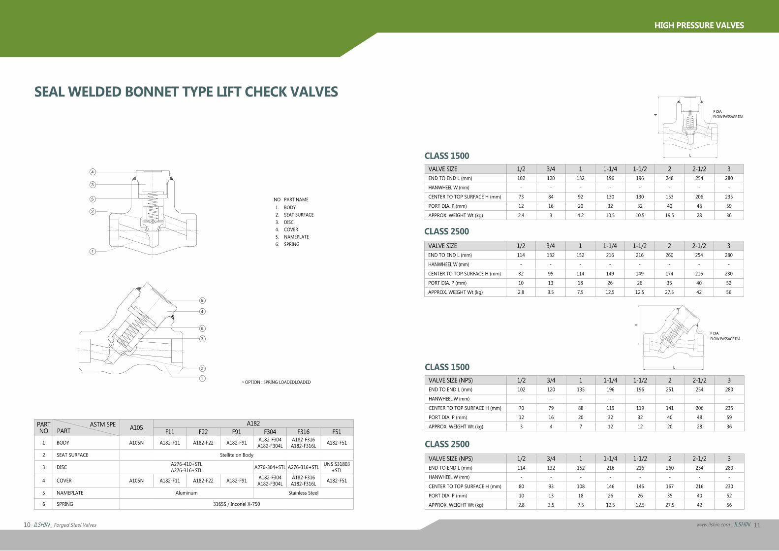
* OPTION : SPRING LOADEDLOADED
PART NO PART ASTM SPE A105 A182
F11 F22 F91 F304 F316 F511 BODY A105N A182-F11 A182-F22 A182-F91 A182-F304
A182-F304LA182-F316 A182-F316L A182-F51
2 SEAT SURFACE Stellite on Body
3 DISC A276-410+STL A276-316+STL A276-304+STL A276-316+STL UNS S31803
+STL
4 COVER A105N A182-F11 A182-F22 A182-F91 A182-F304 A182-F304L
A182-F316 A182-F316L A182-F51
5 NAMEPLATE Aluminum Stainless Steel
6 SPRING 316SS / Inconel X-750
CLASS 1500VALVE SIZE (NPS) 1/2 3/4 1 1-1/4 1-1/2 2 2-1/2 3END TO END L (mm) 102 120 135 196 196 251 254 280
HANWHEEL W (mm) - - - - - - - -
CENTER TO TOP SURFACE H (mm) 70 79 88 119 119 141 206 235
PORT DIA. P (mm) 12 16 20 32 32 40 48 59
APPROX. WEIGHT Wt (kg) 3 4 7 12 12 20 28 36
CLASS 2500VALVE SIZE 1/2 3/4 1 1-1/4 1-1/2 2 2-1/2 3END TO END L (mm) 114 132 152 216 216 260 254 280
HANWHEEL W (mm) - - - - - - - -
CENTER TO TOP SURFACE H (mm) 82 95 114 149 149 174 216 230
PORT DIA. P (mm) 10 13 18 26 26 35 40 52
APPROX. WEIGHT Wt (kg) 2.8 3.5 7.5 12.5 12.5 27.5 42 56
CLASS 2500VALVE SIZE (NPS) 1/2 3/4 1 1-1/4 1-1/2 2 2-1/2 3END TO END L (mm) 114 132 152 216 216 260 254 280
HANWHEEL W (mm) - - - - - - - -
CENTER TO TOP SURFACE H (mm) 80 93 108 146 146 167 216 230
PORT DIA. P (mm) 10 13 18 26 26 35 40 52
APPROX. WEIGHT Wt (kg) 2.8 3.5 7.5 12.5 12.5 27.5 42 56
SEAL WELDED BONNET TYPE LIFT CHECK VALVES
NO1.2.3.4.5.6.
PART NAMEBODYSEAT SURFACEDISCCOVERNAMEPLATESPRING
CLASS 1500VALVE SIZE 1/2 3/4 1 1-1/4 1-1/2 2 2-1/2 3END TO END L (mm) 102 120 132 196 196 248 254 280
HANWHEEL W (mm) - - - - - - - -
CENTER TO TOP SURFACE H (mm) 73 84 92 130 130 153 206 235
PORT DIA. P (mm) 12 16 20 32 32 40 48 59
APPROX. WEIGHT Wt (kg) 2.4 3 4.2 10.5 10.5 19.5 28 36
1
5
4
6
3
2
1
2
5
3
4
P DIA.
H
L
FLOW PASSAGE DIA.
P DIA.
L
H FLOW PASSAGE DIA.
12 ILSHIN _ Forged Steel Valves 13www.ilshin.com _ ILSHIN
HIGH PRESSURE VALVES
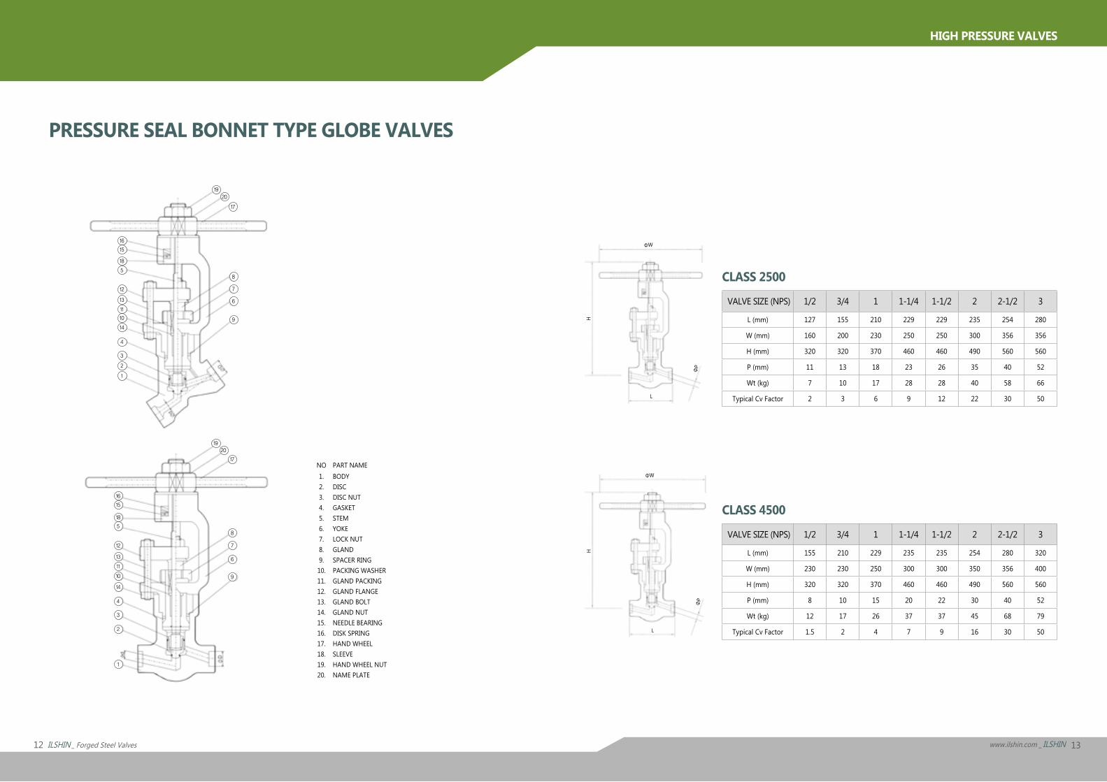
NO1.2.3.4.5.6.7.8.9.10.11.12.13.14.15.16.17.18.19.20.
PART NAMEBODYDISC DISC NUTGASKETSTEMYOKELOCK NUTGLANDSPACER RINGPACKING WASHERGLAND PACKINGGLAND FLANGEGLAND BOLTGLAND NUTNEEDLE BEARINGDISK SPRINGHAND WHEELSLEEVEHAND WHEEL NUTNAME PLATE
CLASS 2500
VALVE SIZE (NPS) 1/2 3/4 1 1-1/4 1-1/2 2 2-1/2 3
L (mm) 127 155 210 229 229 235 254 280
W (mm) 160 200 230 250 250 300 356 356
H (mm) 320 320 370 460 460 490 560 560
P (mm) 11 13 18 23 26 35 40 52
Wt (kg) 7 10 17 28 28 40 58 66
Typical Cv Factor 2 3 6 9 12 22 30 50
CLASS 4500
VALVE SIZE (NPS) 1/2 3/4 1 1-1/4 1-1/2 2 2-1/2 3
L (mm) 155 210 229 235 235 254 280 320
W (mm) 230 230 250 300 300 350 356 400
H (mm) 320 320 370 460 460 490 560 560
P (mm) 8 10 15 20 22 30 40 52
Wt (kg) 12 17 26 37 37 45 68 79
Typical Cv Factor 1.5 2 4 7 9 16 30 50
PRESSURE SEAL BONNET TYPE GLOBE VALVES
ΦW
ΦP
H
L
ΦW
ΦP
H
L
19
16
15
18
5
12
13
11
10
14
4
3
2
1
16
8
17
2019
7
6
9
15
18
5
12
13
11
10
14
4
3
2
1
9
6
7
8
20
17
14 ILSHIN _ Forged Steel Valves 15www.ilshin.com _ ILSHIN
HIGH PRESSURE VALVES
In the supercritical flow condition thethroughput therefore depends solelyon the pressure ρ1 before the valve.
3-3 For steam :The required values must be taken from the steam tables.
3-4 The flow calculation bases on the value must be carried out allowing
for a deviation of approximately ±10%For exeample, the flow through a valvein not wholly independent of thepressure behind the valve in thesupercritical flow condition, as mighttheoretically be assumed, butincreases as the pressure behind thevalve decreases.
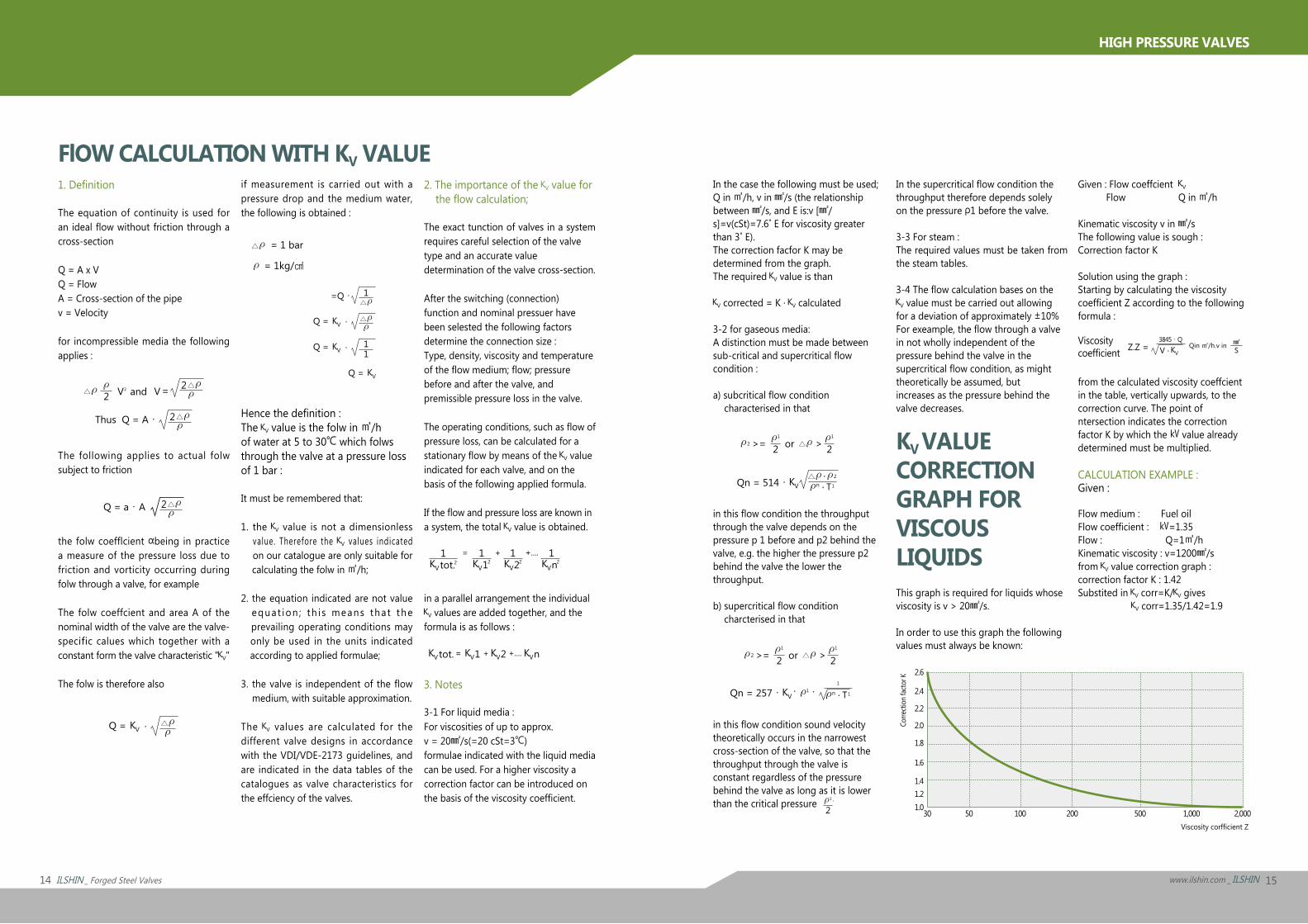
KV VALUE CORRECTION GRAPH FORVISCOUS LIQUIDSThis graph is required for liquids whoseviscosity is v > 20㎟/s.
In order to use this graph the followingvalues must always be known:
1. Definition
The equation of continuity is used for an ideal flow without friction through a cross-section
Q = A x VQ = FlowA = Cross-section of the pipev = Velocity
for incompressible media the following applies :
The following applies to actual folw subject to friction
the folw coefflcient αbeing in practice a measure of the pressure loss due to friction and vorticity occurring during folw through a valve, for example
The folw coeffcient and area A of the nominal width of the valve are the valve-specific calues which together with a constant form the valve characteristic " "
The folw is therefore also
if measurement is carried out with a pressure drop and the medium water, the following is obtained :
Hence the definition :The value is the folw in ㎥/h of water at 5 to 30℃ which folws through the valve at a pressure loss of 1 bar :
It must be remembered that:
1. the value is not a dimensionless value. Therefore the values indicated on our catalogue are only suitable for calculating the folw in ㎥/h;
2. the equation indicated are not value equat ion ; th i s means tha t the prevailing operating conditions may only be used in the units indicated according to applied formulae;
3. the valve is independent of the flow medium, with suitable approximation.
The values are calculated for the different valve designs in accordance with the VDI/VDE-2173 guidelines, and are indicated in the data tables of the catalogues as valve characteristics for the effciency of the valves.
2. The importance of the value for the flow calculation;
The exact tunction of valves in a system requires careful selection of the valvetype and an accurate valuedetermination of the valve cross-section.
After the switching (connection)function and nominal pressuer havebeen selested the following factorsdetermine the connection size :Type, density, viscosity and temperatureof the flow medium; flow; pressurebefore and after the valve, andpremissible pressure loss in the valve.
The operating conditions, such as flow ofpressure loss, can be calculated for astationary flow by means of the valueindicated for each valve, and on thebasis of the following applied formula.
If the flow and pressure loss are known ina system, the total value is obtained.
in a parallel arrangement the individual values are added together, and the
formula is as follows :
3. Notes
3-1 For liquid media :For viscosities of up to approx.v = 20㎟/s(=20 cSt=3℃)formulae indicated with the liquid mediacan be used. For a higher viscosity acorrection factor can be introduced onthe basis of the viscosity coefficient.
In the case the following must be used;Q in ㎥/h, v in ㎟/s (the relationship between ㎟/s, and E is:v [㎟/s]=v(cSt)=7.6˚ E for viscosity greater than 3˚ E).The correction facfor K may bedetermined from the graph.The required value is than
corrected = K · calculated
3-2 for gaseous media:A distinction must be made betweensub-critical and supercritical flowcondition :
a) subcritical flow condition characterised in that
in this flow condition the throughput through the valve depends on the pressure p 1 before and p2 behind the valve, e.g. the higher the pressure p2 behind the valve the lower thethroughput.
b) supercritical flow condition charcterised in that
in this flow condition sound velocitytheoretically occurs in the narrowestcross-section of the valve, so that thethroughput through the valve isconstant regardless of the pressurebehind the valve as long as it is lowerthan the critical pressure
Given : Flow coeffcient Flow Q in ㎥/h
Kinematic viscosity v in ㎟/sThe following value is sough :Correction factor K
Solution using the graph :Starting by calculating the viscositycoefficient Z according to the followingformula :
from the calculated viscosity coeffcientin the table, vertically upwards, to thecorrection curve. The point of ntersection indicates the correction factor K by which the ㎸ value already determined must be multiplied.
CALCULATION EXAMPLE :Given :
Flow medium : Fuel oilFlow coefficient : ㎸=1.35Flow : Q=1㎥/hKinematic viscosity : v=1200㎟/sfrom value correction graph :correction factor K : 1.42Substited in corr=K/ gives
corr=1.35/1.42=1.9
Viscositycoefficient
30
2.6
2.4
2.2
2.0
1.8
1.6
1.41.21.0
50 100 200 500 1,000 2,000
Corre
ction
facto
r K
Viscosity corfficient Z
FlOW CALCULATION WITH KV VALUE
16 ILSHIN _ Forged Steel Valves 17www.ilshin.com _ ILSHIN
HIGH PRESSURE VALVES
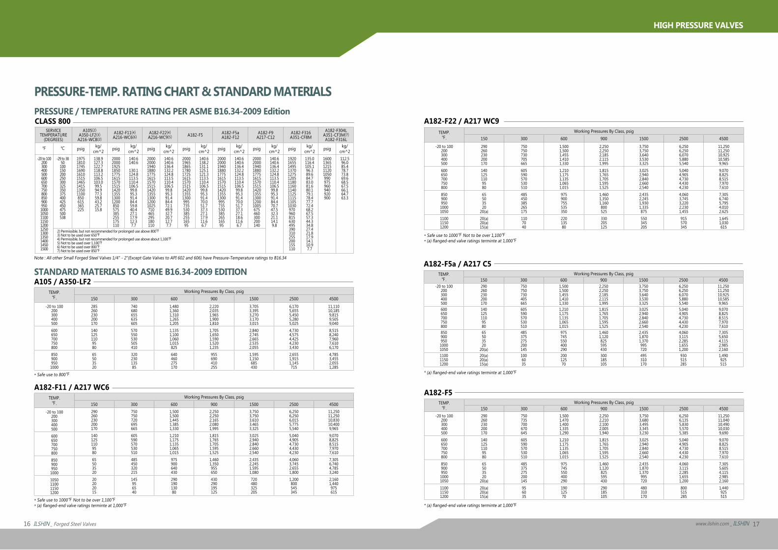
CLASS 800SERVICE
TEMPERATURE(DEGREES)
A105⑵A350-LF2⑶
A216-WCB⑵A182-F11⑷A216-WC6⑹
A182-F22⑷A216-WC9⑸ A182-F5 A182-F5a
A182-F12A182-F9
A217-C12A182-F316A351-CF8M
A182-F304LA351-CF3M⑺A182-F316L
℉ ℃ psig kg/cm^2 psig kg/
cm^2 psig kg/cm^2 psig kg/
cm^2 psig kg/cm^2 psig kg/
cm^2 psig kg/cm^2 psig kg/
cm^2-20 to 100
20030040050060065070075080085090095010001050110011501200125013001350140014501500
-29 to 3850100150200250300325350375400425450475500538
1975 1810 1745 1690 1610 1515 1465 1415 1350 1100 850 615 365 225
138.9 127.3 122.7 118.8 113.2 106.5 103.0 99.5 94.9 77.3 59.8 43.2 25.7 15.8
2000 2000 1925 1850 1775 1615 1570 1515 1420 1355 1300 1200 850 575 385 255 175 110
140.6 140.6
130.1 124.8 113.5 110.4 106.5 99.8 95.3 91.4 84.4 59.8 40.4 27.1 17.9 12.3 7.7
2000 2000 1940 1880 1775 1615 1570 1515 1420 1355 1300 1200 1025 710 465 295 180 110
140.6 140.6 136.4 132.2 124.8 113.5 110.4 106.5 99.8 95.3 91.4 84.4 72.1 49.9 32.7 20.7 12.7 7.7
2000 1965 1865 1780 1725 1615 1570 1515 1420 1355 1300 995 735 530 385 255 165 95
140.6 138.2 131.1 125.1 121.3 113.5 110.4 106.5 99.8 95.3 91.4 70.0 51.7 37.3 27.1 17.9 11.6 6.7
2000 2000 1940 1880 1775 1615 1570 1515 1420 1355 1300 995 735 530 385 265 165 95
140.6 140.6 136.4 132.2 124.8 113.5 110.4 106.5 99.8 95.3 91.4 70.0 51.7 37.3 27.1 18.6 11.6 6.7
2000 2000 1940 1880 1775 1615 1570 1515 1420 1355 1300 1200 1005 675 460 300 200 140
140.6 140.6 136.4 132.2 124.8 113.5 110.4 106.5 99.8 95.3 91.4 84.4 70.7 47.5 32.3 21.1 14.1 9.8
1920 1655 1495 1370 1275 1205 1180 1160 1140 1125 1115 1105 1030 970 960 815 630 495 390 310 255 200 155 110
135.0 116.4 105.1 96.3 89.6 84.7 83.0 81.6 80.1 79.1 78.4 77.7 72.4 68.2 67.5 57.3 44.3 34.8 27.4 21.8 17.9 14.1 10.9 7.7
1600 1365 1215 1120 1050 990 975 960 940 920 900
112.5 96.0 85.4 78.7 73.8 69.6 68.5 67.5 66.1 64.7 63.3
2) Permissible, but not recommended for prolonged use above 800℉3) Not to be used over 650℉4) Permissible, but not recommended for prolonged use above about 1,100℉5) Not to be used over 1,100℉6) Not to be used over 800℉7) Not to be used over 850℉
* Safe use to 1000℉ Not to be over 1,100℉* (a) flanged-end valve ratings terminte at 1,000℉
* (a) flanged-end valve ratings terminte at 1,000℉
* (a) flanged-end valve ratings terminte at 1,000℉
A105 / A350-LF2TEMP.℉.
Working Pressures By Class, psig150 300 600 900 1500 2500 4500
-20 to 100200300400500
285260230200170
740680655635605
1,4801,3601,3101,2651,205
2,2202,0351,9651,9001,810
3,7053,3953,2703,1703,015
6,1705,6555,4505,2805,025
11,11010,1859,8159,5059,040
600650700750800
1401251109580
570550530505410
1,1351,1001,0601,015825
1,7051,6501,5901,5201,235
2,8402,7452,6652,5352,055
4,7304,5754,4254,2303,430
8,5158,2407,9607,6106,170
8509009501000
65503520
32023013585
640460275170
955690410255
1,5951,150685430
2,6551,9151,145715
4,7853,4552,0551,285
* Safe use to 800℉
STANDARD MATERIALS TO ASME B16.34-2009 EDITION
* Safe use to 1000℉ Not to be over 1,100℉* (a) flanged-end valve ratings terminte at 1,000℉
A182-F11 / A217 WC6TEMP.℉.
Working Pressures By Class, psig150 300 600 900 1500 2500 4500
-20 to 100200300400500
290260230200170
750750720695665
1,5001,5001,4451,3851,330
2,2502,2502,1652,0801,995
3,7503,7503,6103,4653,325
6,2506,2506,0155,7755,540
11,25011,25010,83010,4009,965
600650700750800
1401251109580
605590570530510
1,2101,1751,1351,0651,015
1,8151,7651,7051,5951,525
3,0252,9402,8402,6602,540
5,0404,9054,7304,4304,230
9,0708,8258,5157,9707,610
8509009501000
65503520
485450320215
975900640430
1,4601,350955650
2,4352,2451,5951,080
4,0603,7452,6551,800
7,3056,7404,7853,240
1050110011501200
20202015
145956540
29019013080
430290195125
720480325205
1,200800545345
2,1601,440975615
Note : All other Small Forged Steel Valves 1/4" - 2"(Except Gate Valves to API 602 and 606) have Pressure-Temperature ratings to B16.34
PRESSURE / TEMPERATURE RATING PER ASME B16.34-2009 EditionA182-F22 / A217 WC9
TEMP.℉.
Working Pressures By Class, psig150 300 600 900 1500 2500 4500
-20 to 100200300400500
290260230200170
750750730705665
1,5001,5001,4551,4101,330
2,2502,2502,1852,1151,995
3,7503,7503,6403,5303,325
6,2506,2506,0705,8805,540
11,25011,25010,92510,5859,965
600650700750800
1401251109580
605590570530510
1,2101,1751,1351,0651,015
1,8151,7651,7051,5951,525
3,0252,9402,8402,6602,540
5,0404,9054,7304,4304,230
9,0708,8258,5157,9707,610
85090095010001050
65503520
20(a)
485450385265175
975900755535350
1,4601,3501,160800525
2,4352,2451,9301,335875
4,0603,7453,2202,2301,455
7,3056,7405,7954,0102,625
110011501200
20(a)20(a)15(a)
1107040
22013580
330205125
550345205
915570345
1,6451,030615
A182-F5a / A217 C5TEMP.℉.
Working Pressures By Class, psig150 300 600 900 1500 2500 4500
-20 to 100200300400500
290260230200170
750750730405665
1,5001,5001,4551,4101,330
2,2502,2502,1852,1151,995
3,7503,7503,6403,5303,325
6,2506,2506,0705,8805,540
11,25011,25010,92510,5859,965
600650700750800
1401251109580
605590570530510
1,2101,1751,1351,0651,015
1,8151,7651,7051,5951,525
3,0252,9402,8402,6602,540
5,0404,9054,7304,4304,230
9,0708,8258,5157,9707,610
85090095010001050
65503520
20(a)
485375275200145
975745550400290
1,4601,120825595430
2,4351,8701,370995720
4,0603,1152,2851,6551,200
7,3055,6504,1152,9852,160
110011501200
20(a)20(a)15(a)
1006035
20012570
300185105
495310170
930515285
1,490925515
A182-F5TEMP.℉.
Working Pressures By Class, psig150 300 600 900 1500 2500 4500
-20 to 100200300400500
290260230200170
750735700670645
1,5001,4701,4001,3351,290
2,2502,2102,1002,0051,940
3,7503,6803,4953,3453,230
6,2506,1355,8305,5705,385
11,25011,04010,49010,0309,690
600650700750800
1401251109580
605590570530510
1,2101,1751,1351,0651,015
1,8151,7651,7051,5951,525
3,0252,9402,8402,6602,540
5,0404,9054,7304,4304,230
9,0708,8258,5157,9707,610
85090095010001050
65503520
20(a)
485375275200145
975745550400290
1,4601,120825595430
2,4351,8701,370995720
4,0603,1152,2851,6551,200
7,3055,6054,1152,9852,160
110011501200
20(a)20(a)15(a)
956035
19012570
290185105
480310170
800515285
1,440925515
PRESSURE-TEMP. RATING CHART & STANDARD MATERIALS
18 ILSHIN _ Forged Steel Valves 19www.ilshin.com _ ILSHIN
HIGH PRESSURE VALVES
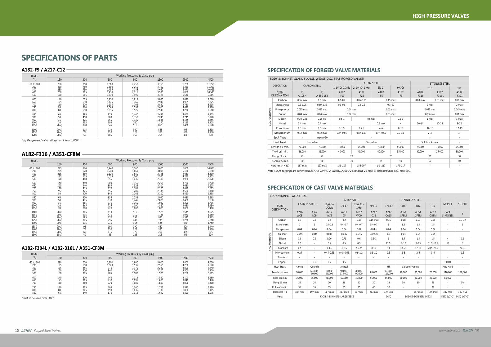
SPECIFICATION OF CAST VALVE MATERIALSBODY & BONNET, WEDGE-DISC
ASTMDESIGNATION
CARBON STEELALLOY STEEL STAINLESS STEEL
MONEL STELLITE11/4 Cr-1/2Mo 5% Cr 21/4 Cr-
1Mo 9& Cr 13% Cr 316 316L 317
A216WCB
A352LCB
A217WC6
A217C5
A217WC9
A217C12
A217CA15
A351CF8M
A351CF3M
A317CG8M
CASH S-MONEL 6
Carbon 0.3 0.3 0.2 0.2 0.18 0.15 max 0.15 0.08 0.03 0.08 - 0.9-1.4Manganses 1 1 0.5-0.8 0.4-0.7 0.4-0.7 0.4-0.7 1 1.5 1.5 1.5 - 1Phosphorus 0.04 0.04 0.04 0.04 0.04 0.04m 0.04 0.04 0.04 0.04 - -
Sulphur 0.045 0.045 0.045 0.045 0.045 0.045m 1.5 0.04 0.04 0.04 - -Silicon 0.6 0.6 0.06 0.75 0.6 0.5-1 1 1.5 1.5 1.5 4 1.5Nickel 0.5 - 0.5 0.5 0.5 11.5- 9-12 9-13 11.5-13.5 63 3
Chromium 0.4 - 1-1.5 4-6.5 2-2.75 8.10 14 18-21 17-21 20.5-23.5 - 27-31Molybdenum 0.25 - 0.45-0.65 0.45-0.65 0.9-1.2 0.9-1.2 0.5 2-3 2-3 3-4 - 1.5
Titanium - - - - - - - - - - - -Copper - 0.5 0.5 0.5 - - - - - - 30.00 -
Heat Treat. Anneal Quench Anneal - HT Solution Anneal - Age Hard -
Tensile psi min. 70,000 65,000-90,000
70,000-90,000
90,000-115,000
70,000-90,000 85,000 90,000-
115,000 70,000 70,000 75,000 110,000 130,000
Yield psi min. 36,000 35,000 40,000 60,000 40,000 55,000 65,000 30,000 30,000 35,000 80,000 -Elong. % min. 22 24 20 18 20 20 18 30 30 25 - 1%R. Area % min. 35 35 35 35 35 40 30 - - 36 - -Hardness HB 187 max 197 max 207 max 217 max 207max 217max 327-381 - 187 max 185 max 387 max 390-451
Parts BODIES-BONNETS-LARGEDISCS DISC BODIES-BONNETS DISCS DISC 1/2"-2" DISC 1/2"-2"
COM
POSI
TON
%
SPECIFICATION OF FORGED VALVE MATERIALSBODY & BONNET, GLAND FLANGE, WEDGE-DISC-SEAT (FORGED VALVES)
DESCRITION CARBON STEELALLOY STEEL STAINLESS STEEL
1-1/4 Cr-1/2Mo 2-1/4 Cr-1 Mo 5% Cr 9% Cr 316 321ASTM
DESIGNA TION2)
A 105N2)
A 350-LF2A182-F11
A182-F22
A182-F5
A182-F9
A182-F316
A182-F316L
A182-F321
Carbon 0.35 max 0.3 max 0.1-0.2 0.05-0.15 0.15 max 0.08 max 0.03 max 0.08 maxManganese 0.6-1.05 0.60-1.35 0.3-0.8 0.3-0.6 0.3-60 2 max 2 maxPhosphorus 0.035 max 0.035 max 0.04 max 0.03 max 0.045 max 0.045 max
Sulfur 0.04 max 0.04 max 0.04 max 0.03 max 0.03 max 0.03 maxSilicon 0.10-0.35 0.15-0.3 0.5-1 0.5max 0.5-1 1 max 1 maxNickel 0.4 max 0.4 max 0.5 max - 10-14 10-15 9-12
Chromium 0.3 max 0.3 max 1-1.5 2-2.5 4-6 8-10 16-18 17-19Molybdenum 0.12 max 0.12 max 0.44-0.65 0.87-1.13 0.44-0.65 0.9-1.1 2-3 3)Spcl. Tests - Impact-50 - - -Heat Treat. Normalize - Normalize - Solution Anneal -
Tensile psi min. 70,000 70,000 70,000 75,000 70,000 85,000 75,000 70,000 75,000Yield psi min. 36,000 36,000 40,000 45,000 40,000 55,000 30,000 25,000 30,000Elong. % min. 22 22 20 20 30 30R. Area % min. 30 30 30 35 40 50 50Hardness* HB1) 187 max 197 max 143-207 156-207 143-217 179-217 - -
COM
POSI
TON
%
Note : 1) All forgings are softer than 237 HB-22HRC. 2) A105N, A350LF2 Standard, 25 max. 3) Titanium: min. 5xC, max. 6xC.
A182-F9 / A217-C12TEMP.℉.
Working Pressures By Class, psig150 300 600 900 1500 2500 4500
-20 to 100200300400500
290260230200170
750750730705665
1,5001,5001,4551,4101,330
2,2502,2502,1852,1151,995
3,7503,7503,6403,5303,325
6,2506,2506,0705,8805,540
11,25011,25010,92510,5859,965
600650700750800
1401251109580
605590570530510
1,2101,1751,1351,0651,015
1,8151,7651,7051,5951,525
3,0252,9402,8402,6602,540
5,0404,9054,7304,4304,230
9,0708,8258,5157,9707,610
85090095010001050
65503520
20(a)
485450375255170
975900755505345
1,4601,3501,130760515
2,4352,2451,8851,270855
4,0603,7453,1452,1151,430
7,3056,7405,6553,8052,570
110011501200
20(a)20(a)20(a)
1157550
225150105
340225155
565375255
945630430
1,6951,130770
A182-F304L / A182-316L / A351-CF3MTEMP.℉.
Working Pressures By Class, psig150 300 600 900 1500 2500 4500
-20 to 100200300400500
230195175160150
600510455420395
1,2001,020910840785
1,8001,5351,3701,2601,180
3,0002,5552,2802,1001,970
5,0004,2603,8003,5003,280
9,0007,6706,8406,3005,905
600650700
140125110
370365360
745730720
1,1151,0951,080
1,8601,8251,800
3,1003,0403,000
5,5805,4705,400
750800850
1108065
355345340
705690675
1,0601,0351,015
1,7651,7301,690
2,9402,8802,820
5,2905,1855,075
A182-F316 / A351-CF8MTEMP.℉.
Working Pressures By Class, psig150 300 600 900 1500 2500 4500
-20 to 100200300400500
275235215195170
720620560515480
1,4401,2401,1201,025955
2,1601,8601,6801,5401,435
3,6003,0952,7952,5702,390
6,0005,1604,6604,2803,980
10,8009,2908,3907,70571,635
600650700750800
1401251109580
450440435425420
900885870855845
1,3551,3251,3051,2801,265
2,2552,2102,1702,1352,110
3,7603,6803,6203,5603,520
6,7706,6256,5156,4106,335
85090095010001050
6550352020
420415385365360
835830775725720
1,2551,2451,1601,0901,080
2,0902,0751,9301,8201,800
3,4803,4603,2203,0303,000
6,2656,2305,7955,4505,400
11001150120012501300
20(a)20(a)20(a)20(a)20(a)
305235185145115
610475370295235
915710555440354
1,5251,185925735585
2,5451,9701,5451,230970
4,5753,5502,7752,2101,750
1350140014501500
20(a)20(a)20(a)15(a)
95756040
19015011585
290225175125
480380290205
800630485345
1,4401,130875620
SPECIFICATIONS OF PARTS
* (a) flanged-end valve ratings terminte at 1,000℉
* Not to be used over 800℉
20 ILSHIN _ Forged Steel Valves 21www.ilshin.com _ ILSHIN
HIGH PRESSURE VALVES
Flush by Hand
L1
L1
E1
E0
30º 30º30º
P
D
L2
L1L2
Tolerance on Product
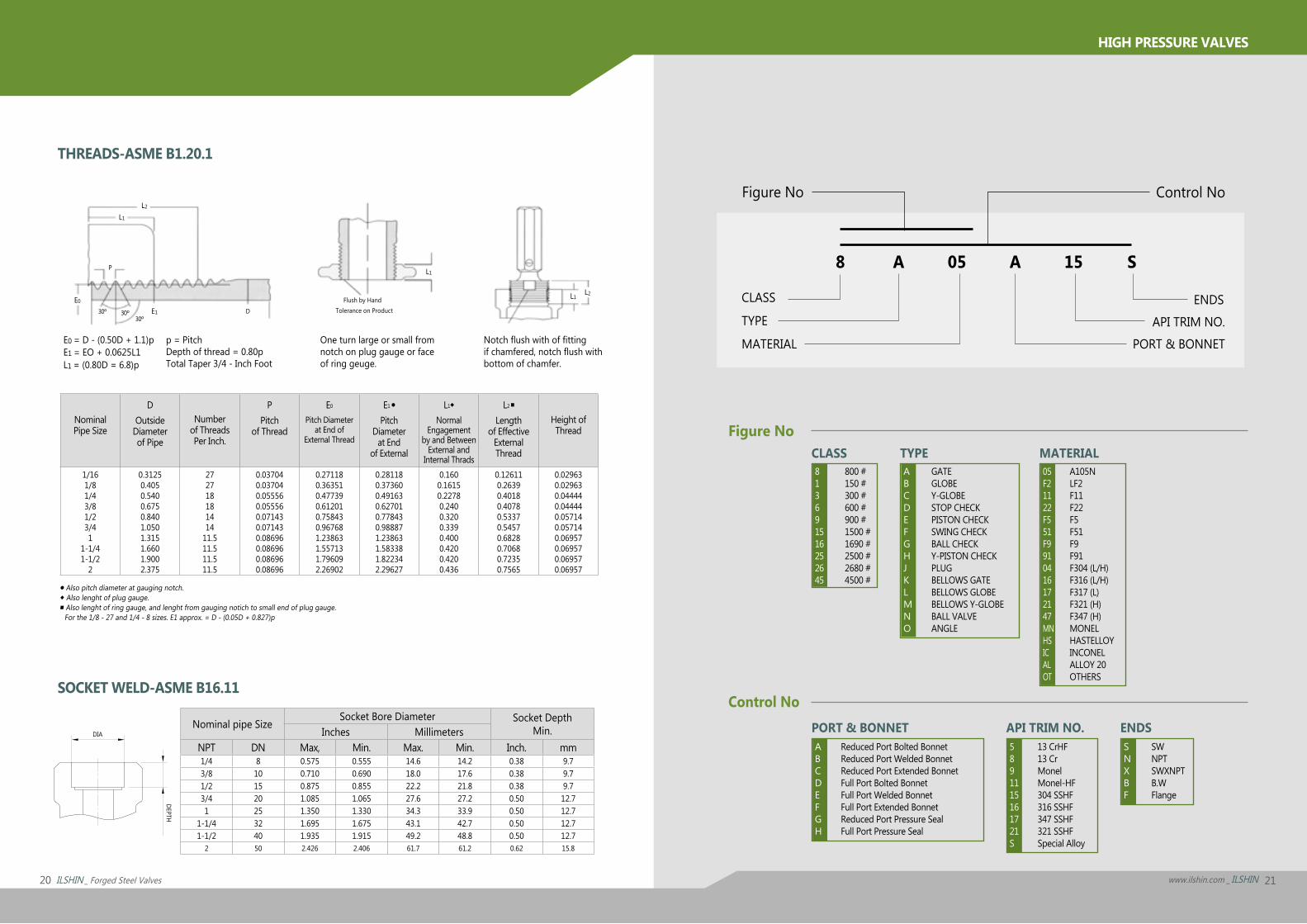
SOCKET WELD-ASME B16.11
● Also pitch diameter at gauging notch.◆ Also lenght of plug gauge.■ Also lenght of ring gauge, and lenght from gauging notich to small end of plug gauge.
For the 1/8 - 27 and 1/4 - 8 sizes. E1 approx. = D - (0.05D + 0.827)p
NominalPipe Size
DOutside
Diameterof Pipe
Numberof ThreadsPer Inch.
PPitch
of Thread
E0
Pitch Diameterat End of
External Thread
E1 ●
PitchDiameter
at Endof External
L1◆
NormalEngagement
by and BetweenExternal and
Internal Thrads
L2 ■
Lengthof Effective
ExternalThread
Height ofThread
1/161/81/43/81/23/41
1-1/41-1/2
2
0.31250.4050.5400.6750.8401.0501.3151.6601.9002.375
272718181414
11.511.511.511.5
0.037040.037040.055560.055560.071430.071430.086960.086960.086960.08696
0.271180.363510.477390.612010.758430.967681.238631.557131.796092.26902
0.281180.373600.491630.627010.778430.988871.238631.583381.822342.29627
0.1600.16150.22780.2400.3200.3390.4000.4200.4200.436
0.126110.26390.40180.40780.53370.54570.68280.70680.72350.7565
0.029630.029630.044440.044440.057140.057140.069570.069570.069570.06957
Nominal pipe SizeSocket Bore Diameter Socket Depth
Min.Inches MillimetersNPT DN Max, Min. Max. Min. Inch. mm1/4 8 0.575 0.555 14.6 14.2 0.38 9.73/8 10 0.710 0.690 18.0 17.6 0.38 9.71/2 15 0.875 0.855 22.2 21.8 0.38 9.73/4 20 1.085 1.065 27.6 27.2 0.50 12.71 25 1.350 1.330 34.3 33.9 0.50 12.7
1-1/4 32 1.695 1.675 43.1 42.7 0.50 12.71-1/2 40 1.935 1.915 49.2 48.8 0.50 12.7
2 50 2.426 2.406 61.7 61.2 0.62 15.8
TYPE
API TRIM NO.
CLASS
PORT & BONNET ENDS
MATERIAL
THREADS-ASME B1.20.1
One turn large or small fromnotch on plug gauge or faceof ring geuge.
Notch flush with of fittingif chamfered, notch flush withbottom of chamfer.
E0 = D - (0.50D + 1.1)pE1 = EO + 0.0625L1L1 = (0.80D = 6.8)p
p = PitchDepth of thread = 0.80pTotal Taper 3/4 - Inch Foot
Figure No
CLASS ENDSTYPE API TRIM NO.MATERIAL PORT & BONNET
8 A 05 A 15 S
Control No
DEPTH
DIA
813691516252645
800 #150 #300 #600 #900 #1500 #1690 #2500 #2680 #4500 #
ABCDEFGHJKLMNO
GATEGLOBEY-GLOBESTOP CHECKPISTON CHECKSWING CHECKBALL CHECKY-PISTON CHECKPLUGBELLOWS GATEBELLOWS GLOBEBELLOWS Y-GLOBEBALL VALVEANGLE
ABCDEFGH
Reduced Port Bolted BonnetReduced Port Welded BonnetReduced Port Extended BonnetFull Port Bolted BonnetFull Port Welded BonnetFull Port Extended BonnetReduced Port Pressure SealFull Port Pressure Seal
5891115161721S
13 CrHF13 CrMonelMonel-HF304 SSHF316 SSHF347 SSHF321 SSHFSpecial Alloy
SNXBF
SWNPTSWXNPTB.WFlange
05F21122F551F9910416172147MNHSICALOT
A105NLF2F11F22F5F51F9F91F304 (L/H)F316 (L/H)F317 (L)F321 (H)F347 (H)MONELHASTELLOYINCONELALLOY 20OTHERS
Figure No
Control No

ILSHIN VALVE CO., LTD.www.ilshin.com|E-mail. [email protected]
1 Na 703, Sihwa Industrial Complex, 1244-2Jeongwang-Dong, Siheung-Si, Gyeonggi-Do, Zip Code 429-912, KOREA
Tel. 82-31-433-8176|Fax. 82-31-433-8178
PRIN
TED
IN K
OREA
, MAY
201
2 / D
esig
n FI
ine
Grou
p|+8
2.2.
2278
.018
8|w
ww
.sdi
0102
03.co
m|
Related Documents