High Precision &Torque Control LS Vector Drive STARVERT iV5 2.2~37kW 3 Phase 200~230V 2.2~800kW 3 Phase 380~460V 5.5~500kW DC Input type www.lsis.com

Welcome message from author
This document is posted to help you gain knowledge. Please leave a comment to let me know what you think about it! Share it to your friends and learn new things together.
Transcript

High Precision &Torque Control LS Vector Drive
STARVERT iV52.2~37kW 3 Phase 200~230V
2.2~800kW 3 Phase 380~460V5.5~500kW DC Input type
www.lsis.com

Our lives with STARVERT iV5
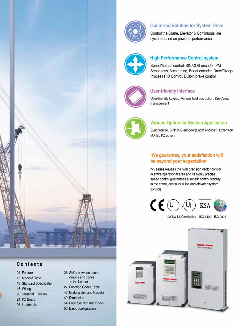
Optimized Solution for System DriveControl the Crane, Elevator & Continuous line system based on powerful performance
High Performance Control systemSpeed/Torque control, SIN/COS encoder, PM Sensorless, Auto tuning, Endat encoder, Draw/Droop/Process PID Control, Built-in brake control
User-friendly Interface
Various Option for System Application
User-friendly keypad, Various field bus option, DriveView management
Synchronize, SIN/COS encoder(Endat encoder), Extension I/O, EL I/O option
C o n t e n t s04 Features12 Model & Type13 Standard Specification16 Wiring22 Terminal Function24 I/O Board25 Loader Use
26 Shifts between each groups and codes in the Loader27 Function Codes Table47 Braking Unit and Resistor49 Dimension54 Fault Solution and Check55 Basic configuration
220kW UL Certification ISO 14001, ISO 9001
‘We guarantee, your satisfaction will be beyond your expectation’iV5 series realizes the high precision vector control in entire operational area and its highly precise speed control guarantees a superb control stability in the crane, continuous line and elevator systemcontrols.
� � � � �� �
Features
04
System Drive
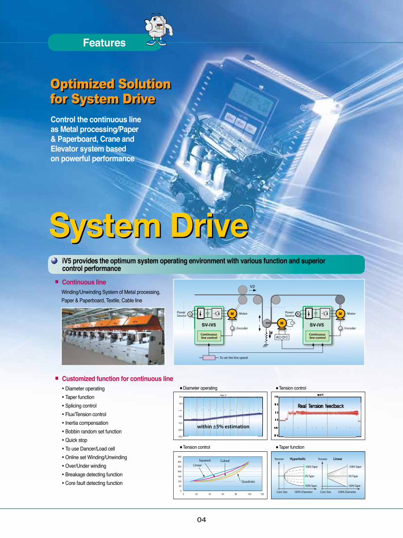
Optimized Solution for System DriveOptimized Solution for System DriveControl the continuous line as Metal processing/Paper & Paperboard, Crane and Elevator system based on powerful performance
■Tension control ■Taper function
■Diameter operating ■Tension control
iV5 provides the optimum system operating environment with various function and superior control performance
■ Continuous line Winding/Unwinding System of Metal processing, Paper & Paperboard, Textile, Cable line
■ Customized function for continuous line • Diameter operating• Taper function• Splicing control• Flux/Tension control• Inertia compensation• Bobbin random set function• Quick stop• To use Dancer/Load cell• Online set Winding/Unwinding• Over/Under winding• Breakage detecting function• Core fault detecting function
System Drive
05
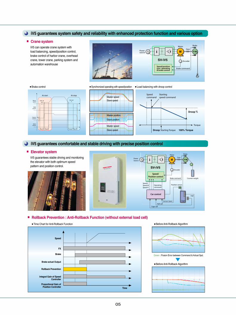
■ Rollback Prevention : Anti-Rollback Function (without external load cell) ■Time Chart for Anti-Rollback Function
Green : Posion Error between Command & Actual Spd.
■Before Anti-Rollback Algorithm
■Before Anti-Rollback Algorithm
■Brake control ■Synchronized operating with speed/position ■Load balancing with droop control
iV5 guarantees system safety and reliability with enhanced protection function and various option■ Crane system
iV5 can operate crane system with load balancing, speed/position control, brake control of harbor crane, overhead crane, tower crane, parking system and automation warehouse
iV5 guarantees comfortable and stable driving with precise position control■ Elevator system
iV5 guarantees stable driving and monitoring the elevator with both optimum speed pattern and position control.
◀
Master speed
Master position
Master speed
Slave speed
Slave position
Slave speed
Speed
Time
FX
Brake
Brake actual Output
Rollback Prevention
Integral Gain of SpeedController
Proportional Gain ofPosition Controller
� � � � �� �
Features
06
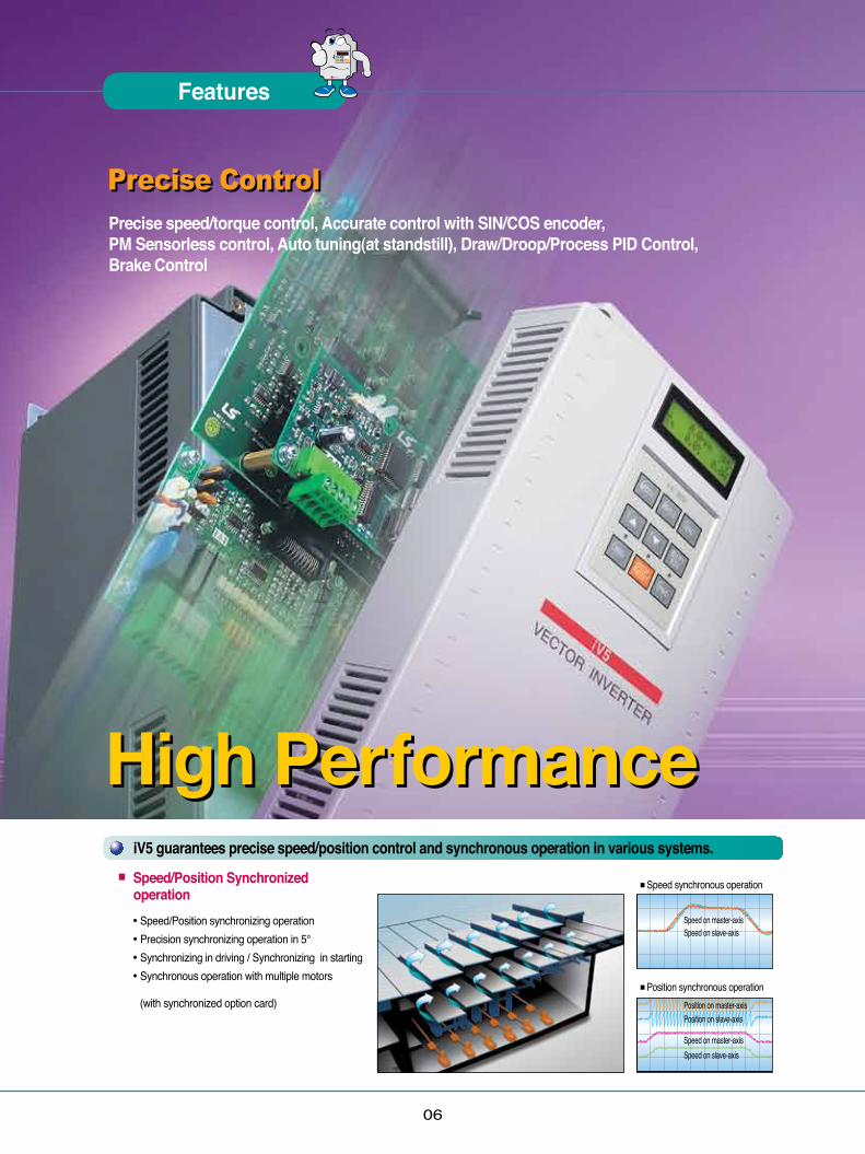
iV5 guarantees precise speed/position control and synchronous operation in various systems.■ Speed/Position Synchronized operation
• Speed/Position synchronizing operation• Precision synchronizing operation in 5°• Synchronizing in driving / Synchronizing in starting • Synchronous operation with multiple motors
(with synchronized option card)
Precise ControlPrecise ControlPrecise speed/torque control, Accurate control with SIN/COS encoder,PM Sensorless control, Auto tuning(at standstill), Draw/Droop/Process PID Control, Brake Control
■Position synchronous operation
■Speed synchronous operation
Speed on master-axis
Position on master-axis
Speed on master-axis
Speed on slave-axis
Position on slave-axis
Speed on slave-axis
High PerformanceHigh Performance

07
Autotuning■ Standstill autotuning
This unique technology of LS allows the autotuning operation to be performed even with the motor shaft directly connected to the load. Especially, this standstill type autotuning is very useful in the lift application because it does not require removal of brake coupling connected to the motor.
Precise and safe control system■ Draw/Droop/Process PID control
Draw/Droop/Process PID control is provided for precise control such as tension control, linear velocity control, temperature and pressure control and useful functions easily implemented like Load balancing.
Built-in brake control for vertical loading safety■ Brake Control
For applications which have a risk of dropping, for instance elevator and crane system, brake control is built in
Extreme precise control■ SIN/COS encoder option
With SIN/COS encoder option, users can control more precisely than normal encoder
SPM, IPM motor control without any sensors■ Synchronous motor sensorless control
With synchronous motor sensorless control functions including initial stimulus position estimation, it perfectly controls SPM, IPM motor without additional sensor.
• SPM, IPM motor • Within ±5 ̊error estimation• Sensorless 30,000rpm driving Fast reponse within 100msec• A variety of applications such as hydraulic pumps, high-speed compressor, turbo blower
** Please contact us for SPM, IPM motor drive
■ Rotation autotuning This type of autotuning has been widely used for the vector control drive. As the name implies, this requires the motor shaft to be free of the coupling for a proper operation.
◀
■Draw control
■Draw control
• SPM • IPM
■Droop control
■Process PID control
� � � � �� �
Features
08
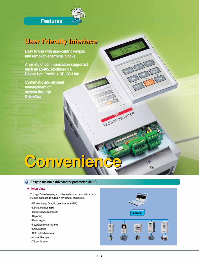
Easy to maintain drive/motor parameter via PC■ Drive View
Through DriveView program, drive system can be monitored with PC and managed to maintain drive/motor parameters.
• Window based Graphic User Interface (GUI)• LS485, Modbus-RTU• Max 31 drives connection• Reporting• Event logging• Integrated control console• Offline editing• Data upload/download• 4ch oscilloscope• Trigger function
User Friendly InterfaceUser Friendly InterfaceEasy to use with user-centric keypad and removable terminal blocks
A variety of communication supported such as LS485, Modbus-RTU, Device Net, Profibus-DP, CC-Link
Systematic and efficient management of system through DriveView
Convenience
Converter
Convenience
09
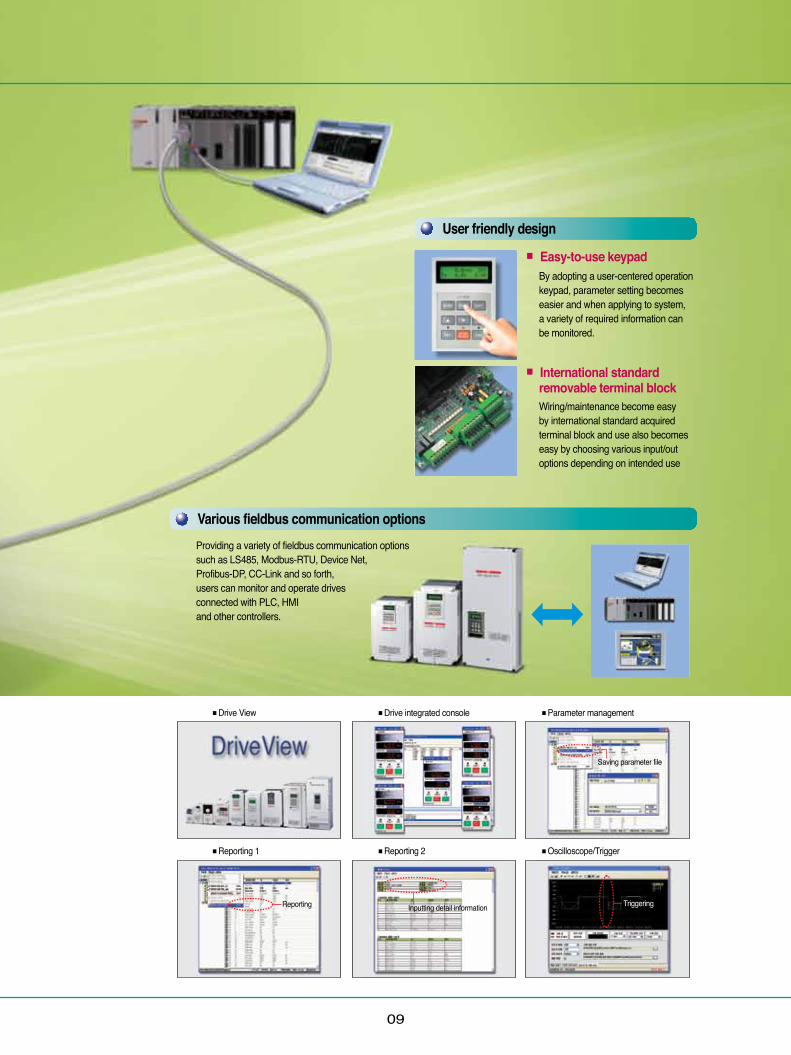
User friendly design■ Easy-to-use keypad
By adopting a user-centered operation keypad, parameter setting becomes easier and when applying to system, a variety of required information can be monitored.
■ International standard removable terminal block
Wiring/maintenance become easy by international standard acquired terminal block and use also becomes easy by choosing various input/out options depending on intended use
Various fieldbus communication optionsProviding a variety of fieldbus communication options such as LS485, Modbus-RTU, Device Net, Profibus-DP, CC-Link and so forth, users can monitor and operate drives connected with PLC, HMI and other controllers.
■Drive View ■Drive integrated console ■Parameter management
Saving parameter file
Inputting detail information Reporting Triggering
■Reporting 1 ■Reporting 2 ■Oscilloscope/Trigger
� � � � �� �
Features
10
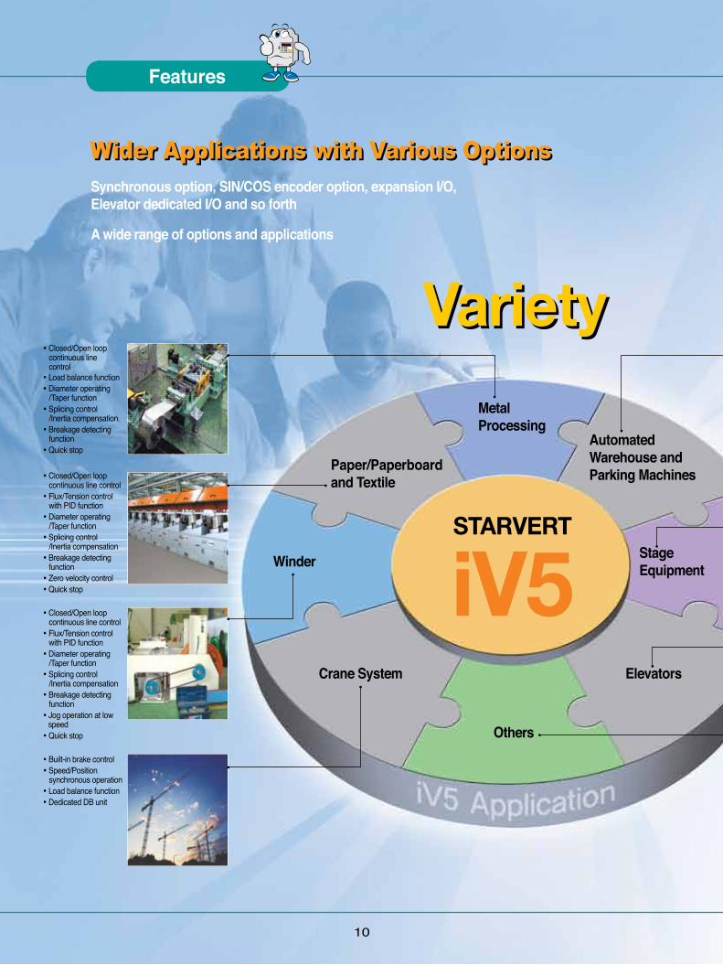
Wider Applications with Various OptionsWider Applications with Various OptionsSynchronous option, SIN/COS encoder option, expansion I/O, Elevator dedicated I/O and so forth
A wide range of options and applications
Variety
STARVERT
iV5
Paper/Paperboard and Textile
Metal Processing
Automated Warehouse andParking Machines
Winder
Crane System
Others
Elevators
Stage Equipment
• Closed/Open loop continuous line control• Load balance function• Diameter operating /Taper function• Splicing control /Inertia compensation• Breakage detecting function• Quick stop
• Closed/Open loop continuous line control• Flux/Tension control with PID function• Diameter operating /Taper function• Splicing control /Inertia compensation• Breakage detecting function• Zero velocity control• Quick stop
• Closed/Open loop continuous line control• Flux/Tension control with PID function• Diameter operating /Taper function• Splicing control /Inertia compensation• Breakage detecting function• Jog operation at low speed• Quick stop
• Built-in brake control• Speed/Position synchronous operation• Load balance function• Dedicated DB unit
Variety

11
Elevators
Stage Equipment
• Built-in brake control• Load balance function• Dedicated DB unit• Zero velocity control• Precise control through SIN/COS encoder
• Speed/Position synchronous operation• Load balance function• Precise control through SIN/COS encoder• Zero velocity control• Smooth acceleration and deceleration
• Elevator dedicated control mode• Geared/gearless elevator operation• Precise control through SIN/COS encoder Elevator master function with on-board option• Optimum speed pattern / no creep speed• Battery operation during blackout• Load cell optimum compensation
• Machine tools / press• Cart• Hydraulic pump, high speed compressor, tower blower and so forth
■ Synchronization option • Speed/Position synchronizing operation• Consuming current : 300mA• Input frequency : 100kHz• Open collector output• Multiple band operation
■ Elevator I/O • Position sensor/Safety switch input• Car position output• E/L position and sequence control• MC/Brake operation signal output• E/L exclusive connector
■ Device Net • 125/250/500kbps speed• Bus topology• Max. 64 node• Max. 500m (125kbps)• Enhanced online diagnosis function
■ Extension I/O • Analog input : 5 channel• Analog output : 2 channel• Other functions are same as SIO board
■ SIN/COS + Endat encoder option• Selectable Endat & Sin/Cos Option • Max. 3,600rpm speed• Enhanced Comfortable feeling in Car - Compatibility with Heidenhain Encorder - ECN413, ECN1313, ERN487, ERN1387
*Note1) Please contact us to control continuous lines with open loop control*Note1) For more than 4 analog inputs, users need to additionally purchase expansion I/O.
■ LS485/Modbus-RTU • 1200/2400/4800/9600/19200/38400 bps speed Bus, Multidrop link system• Max. 31 node• Max. 1200m period (recommended 700m)
■ Profibus-DP • Max. 12Mbps speed• Max. 32 station• Bus topology• Enhanced online diagnosis function
■ 24V Encoder I/O • 24V encoder• Encoder power fault detection• Other specifications are same as SIO
■ CC-Link • Max. 10Mbps speed• Customized LS profile• CC Link customized cable• Built-in termination resistor• Remote I/O : each 32 point• Remote register : 4 words
iV5 Option
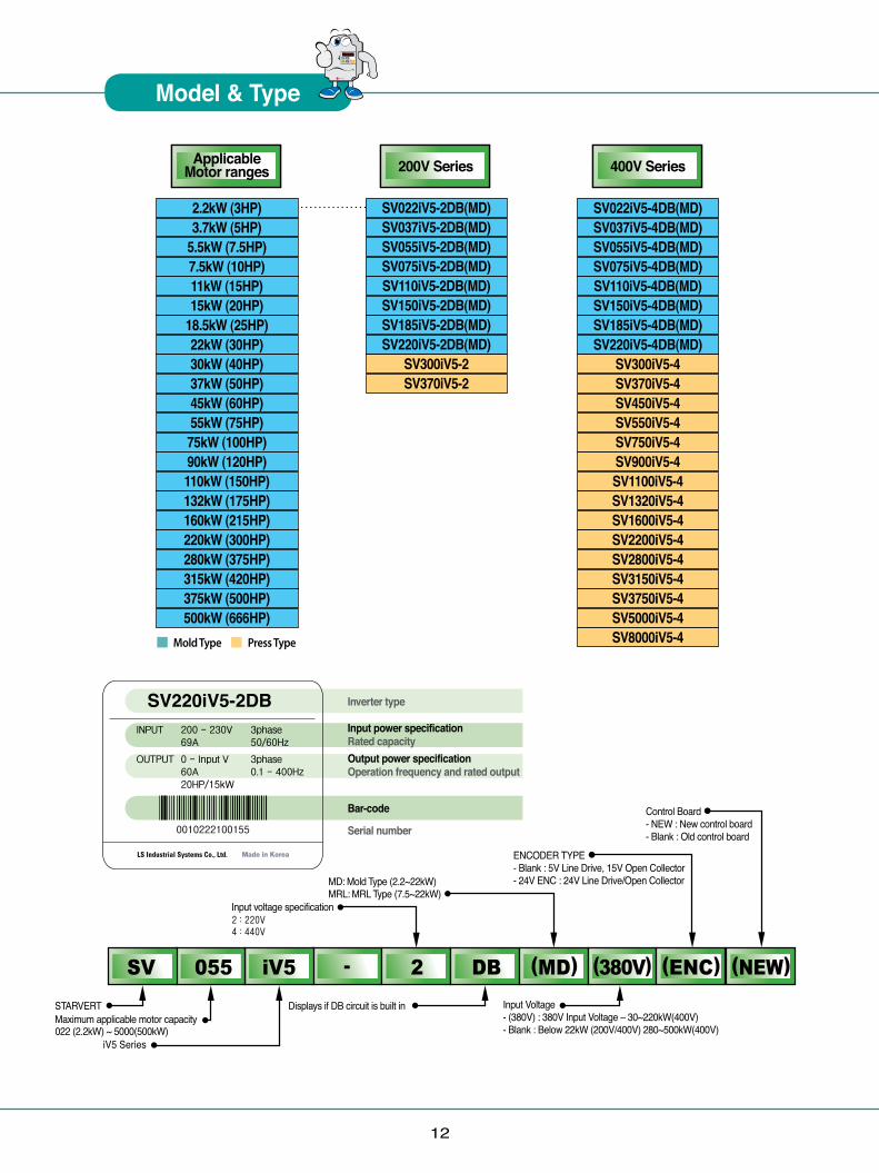
2.2kW (3HP)3.7kW (5HP)
5.5kW (7.5HP)7.5kW (10HP)11kW (15HP)15kW (20HP)
18.5kW (25HP)22kW (30HP)30kW (40HP)37kW (50HP)45kW (60HP)55kW (75HP)75kW (100HP)90kW (120HP)110kW (150HP)132kW (175HP)160kW (215HP)220kW (300HP)280kW (375HP)315kW (420HP)375kW (500HP)500kW (666HP)
12
Applicable Motor ranges
SV022iV5-2DB(MD)SV037iV5-2DB(MD)SV055iV5-2DB(MD)SV075iV5-2DB(MD)SV110iV5-2DB(MD)SV150iV5-2DB(MD)SV185iV5-2DB(MD)SV220iV5-2DB(MD)
SV300iV5-2SV370iV5-2
SV022iV5-4DB(MD)SV037iV5-4DB(MD)SV055iV5-4DB(MD)SV075iV5-4DB(MD)SV110iV5-4DB(MD)SV150iV5-4DB(MD)SV185iV5-4DB(MD)SV220iV5-4DB(MD)
SV300iV5-4SV370iV5-4SV450iV5-4SV550iV5-4SV750iV5-4SV900iV5-4SV1100iV5-4SV1320iV5-4SV1600iV5-4SV2200iV5-4SV2800iV5-4SV3150iV5-4SV3750iV5-4SV5000iV5-4SV8000iV5-4
200V Series 400V Series
Mold Type Press Type
� � � � �� �
Model & Type
13
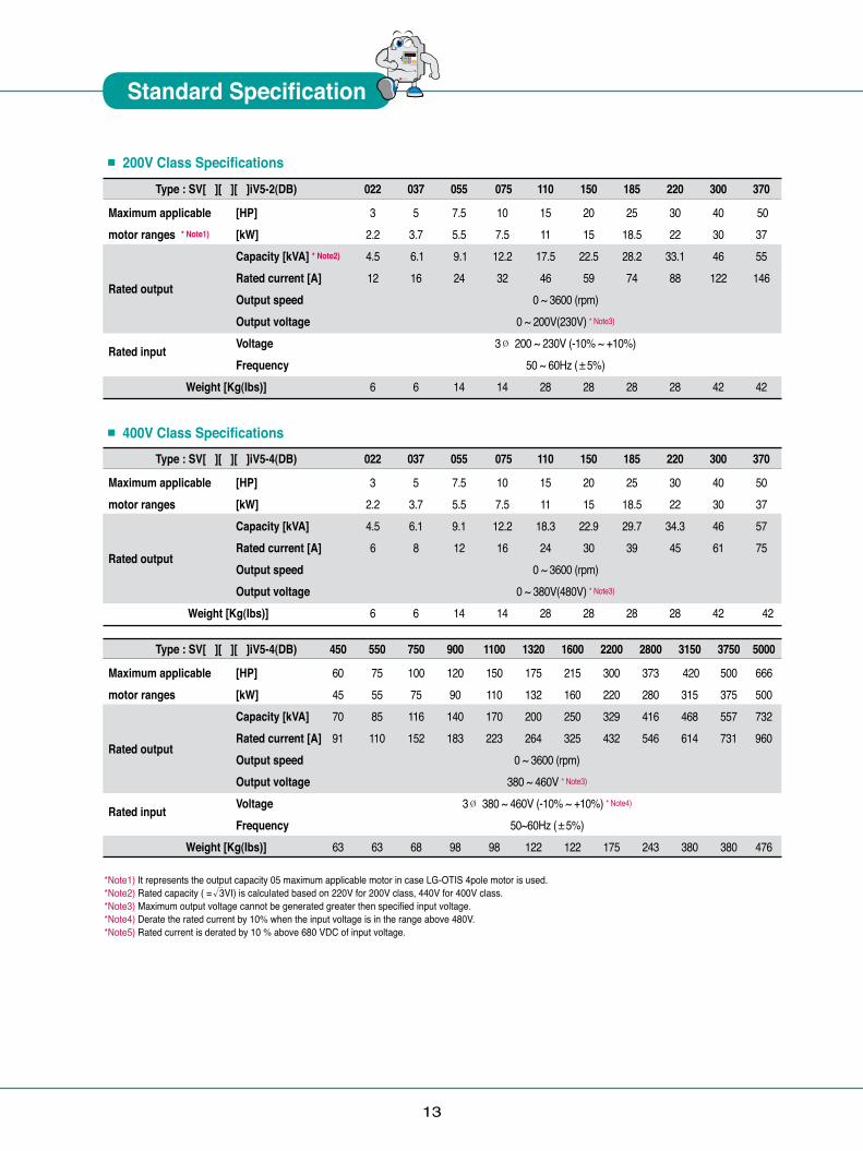
■ 200V Class Specifications Type : SV[ ][ ][ ]iV5-2(DB)
Maximum applicable [HP] motor ranges * Note1) [kW] Capacity [kVA] * Note2)
Rated output Rated current [A]
Output speed Output voltage Rated input Voltage Frequency
Weight [Kg(Ibs)]
022 037 055 075 110 150 185 220 300 370
3 5 7.5 10 15 20 25 30 40 50 2.2 3.7 5.5 7.5 11 15 18.5 22 30 37 4.5 6.1 9.1 12.2 17.5 22.5 28.2 33.1 46 55 12 16 24 32 46 59 74 88 122 146
0 ~ 3600 (rpm)0 ~ 200V(230V) * Note3)
3Ø 200 ~ 230V (-10% ~ +10%)50 ~ 60Hz (±5%)
6 6 14 14 28 28 28 28 42 42
■ 400V Class Specifications Type : SV[ ][ ][ ]iV5-4(DB)
Maximum applicable [HP] motor ranges [kW] Capacity [kVA]
Rated output Rated current [A]
Output speed Output voltage Weight [Kg(Ibs)]
022 037 055 075 110 150 185 220 300 370
3 5 7.5 10 15 20 25 30 40 50 2.2 3.7 5.5 7.5 11 15 18.5 22 30 37 4.5 6.1 9.1 12.2 18.3 22.9 29.7 34.3 46 57 6 8 12 16 24 30 39 45 61 75
0 ~ 3600 (rpm)0 ~ 380V(480V) * Note3)
6 6 14 14 28 28 28 28 42 42
Type : SV[ ][ ][ ]iV5-4(DB)
Maximum applicable [HP] motor ranges [kW] Capacity [kVA]
Rated output Rated current [A]
Output speed Output voltage Rated input Voltage Frequency
Weight [Kg(Ibs)]
450 550 750 900 1100 1320 1600 2200 2800 3150 3750 5000
60 75 100 120 150 175 215 300 373 420 500 666 45 55 75 90 110 132 160 220 280 315 375 500 70 85 116 140 170 200 250 329 416 468 557 732 91 110 152 183 223 264 325 432 546 614 731 960
0 ~ 3600 (rpm)380 ~ 460V * Note3)
3Ø 380 ~ 460V (-10% ~ +10%) * Note4)
50~60Hz (±5%) 63 63 68 98 98 122 122 175 243 380 380 476
*Note1) It represents the output capacity 05 maximum applicable motor in case LG-OTIS 4pole motor is used.*Note2) Rated capacity ( = 3VI) is calculated based on 220V for 200V class, 440V for 400V class.*Note3) Maximum output voltage cannot be generated greater then specified input voltage.*Note4) Derate the rated current by 10% when the input voltage is in the range above 480V.*Note5) Rated current is derated by 10 % above 680 VDC of input voltage.
√
Standard Specification
� � � � �� �
14
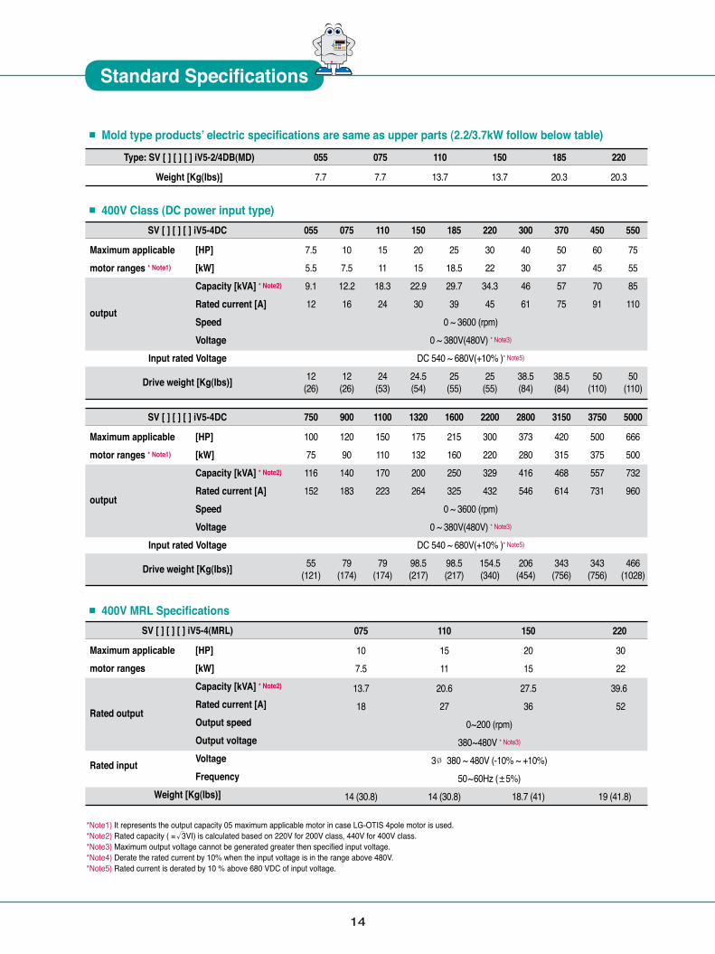
*Note1) It represents the output capacity 05 maximum applicable motor in case LG-OTIS 4pole motor is used.*Note2) Rated capacity ( = 3VI) is calculated based on 220V for 200V class, 440V for 400V class.*Note3) Maximum output voltage cannot be generated greater then specified input voltage.*Note4) Derate the rated current by 10% when the input voltage is in the range above 480V.*Note5) Rated current is derated by 10 % above 680 VDC of input voltage.
√
■ Mold type products ̓electric specifications are same as upper parts (2.2/3.7kW follow below table)
■ 400V MRL Specifications
■ 400V Class (DC power input type)
Type: SV [ ] [ ] [ ] iV5-2/4DB(MD)
Weight [Kg(Ibs)]
055 075 110 150 185 220
7.7 7.7 13.7 13.7 20.3 20.3
075 110 150 220
10 15 20 30 7.5 11 15 22
13.7 20.6 27.5 39.6 18 27 36 52
0~200 (rpm)380~480V * Note3)
3Ø 380 ~ 480V (-10% ~ +10%) 50~60Hz (±5%)
14 (30.8) 14 (30.8) 18.7 (41) 19 (41.8)
SV [ ] [ ] [ ] iV5-4(MRL)
Maximum applicable [HP] motor ranges [kW] Capacity [kVA] * Note2)
Rated output Rated current [A]
Output speed Output voltage Rated input Voltage Frequency
Weight [Kg(Ibs)]
SV [ ] [ ] [ ] iV5-4DC
Maximum applicable [HP] motor ranges * Note1) [kW] Capacity [kVA] * Note2)
output Rated current [A]
Speed Voltage
Input rated Voltage
Drive weight [Kg(Ibs)]
SV [ ] [ ] [ ] iV5-4DC
Maximum applicable [HP] motor ranges * Note1) [kW] Capacity [kVA] * Note2)
output Rated current [A]
Speed Voltage
Input rated Voltage
Drive weight [Kg(Ibs)]
055 075 110 150 185 220 300 370 450 550
7.5 10 15 20 25 30 40 50 60 75 5.5 7.5 11 15 18.5 22 30 37 45 55 9.1 12.2 18.3 22.9 29.7 34.3 46 57 70 85 12 16 24 30 39 45 61 75 91 110
0 ~ 3600 (rpm)0 ~ 380V(480V) * Note3)
DC 540 ~ 680V(+10% )* Note5)
12 12 24 24.5 25 25 38.5 38.5 50 50 (26) (26) (53) (54) (55) (55) (84) (84) (110) (110)
750 900 1100 1320 1600 2200 2800 3150 3750 5000
100 120 150 175 215 300 373 420 500 666 75 90 110 132 160 220 280 315 375 500 116 140 170 200 250 329 416 468 557 732 152 183 223 264 325 432 546 614 731 960
0 ~ 3600 (rpm)0 ~ 380V(480V) * Note3)
DC 540 ~ 680V(+10% )* Note5)
55 79 79 98.5 98.5 154.5 206 343 343 466 (121) (174) (174) (217) (217) (340) (454) (756) (756) (1028)
� � � � �� �
Standard Specifications

15
Speed setting
Input
Output
Analog input
Digital input
Analog output
Digital output
Open collector output
Protection function
Installation environmentAmbient temperature
Ambient humidityCooling method
Altitude / Vibration
Environment
Digital settingMulti-step-speed setup by digital inputAnalog input setting of -10~10V or 4~20mASetting by options3Channels (AI1, AI2, AI3)-10 ~ 10V, 4 ~ 20mA, 10 ~ 0V, 20 ~ 4mA, motor NTC (selectable)Selectable among 9 different multi-function analog inputsFX, RX, BX, RST, P1 ~ P7Multi function input terminal (P1~P7) can be selected among 27 functions.2-Channel (AO1, AO2)-10 ~ 10V outputSelective among 31 multi-function analog output functionsMulti function digital output: 2channels (1A-1B, 2A-2B)Fault digital output: 1channel (30A-30C, 30B-30C)1channel (OCI/EG)Over current, Over/Low voltage, Drive overheat, Drive thermal sensor open, Motor over heat, Motor thermal sensor open, Over speed, IGBT gate blocking (BX), Fuse open, Trip by unusual external signal, Encoder error, Communication error, Electronic thermal, Stall prevention (V/F), Over load(V/F), Drive over loadIndoor, free of corrosive gas and direct sunlight-10 ~ 40C (Non frozen condition)Below RH90% (Dew free)Forced cooling by FANBelow 1000 meters/ above sea level 5.9㎨ (=0.6G)
■ Common Specifications
Response speedtorque control V / F patterntorque BoostTime setup
Combination Pattern
Control type
Frequency / Speed control accuracy
Frequency / Speed resolution
Braking typeBraking torqueBraking resistor
Circuit type
Item
IGBT adopted voltage type drive
Specification
Speed sensor use vector type control Open loop control: V/F control (90-220kW)Analog: ± 0.2% of maximum command speed (25±10℃) Digital: ±0.01% of maximum command speed (0~40℃)Analog: ±0.05% of maximum command speed Digital: 0.01% of maximum command speed50Hz3% Linear, Square, User V/FManual torque boost(0-20%), Automatic torque boost0.00-6000.0 sec (Time unit can be set)4 combined of Acc/Dec eleration timeLinear, S-CurveDynamic braking using external resistor150% An external braking resistor is required
Vector
V / F
SpeedACC/DEC
Braking
Control
16
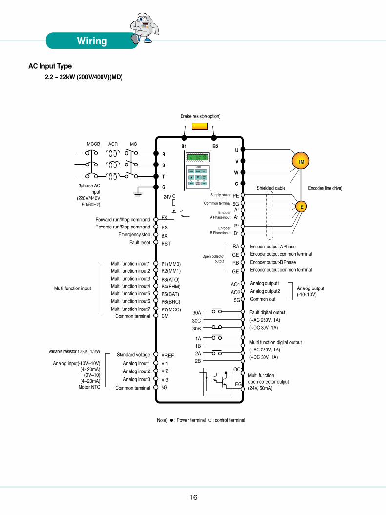
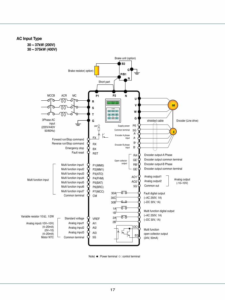
2.2 ~ 22kW (200V/400V)(MD)AC Input Type
MCCB MC
24V
3phase AC input
(220V/440V50/60Hz)
ACR
Multi function input1Multi function input2Multi function input3
Forward run/Stop commandReverse run/Stop command
Emergency stopFault reset
Multi function input4Multi function input5Multi function input6Multi function input7
Multi function input
Variable resistor 10㏀, 1/2W
Analog input(-10V~10V)(4~20mA)
(0V~10)(4~20mA)
Motor NTC
Common terminal
Standard voltageAnalog input1Analog input2Analog input3
Common terminal
Analog output1Analog output2Common out
Encoder output-A PhaseEncoder output common terminalEncoder output-B PhaseEncoder output common terminal
Multi function open collector output(24V, 50mA)
Multi function digital output(~AC 250V, 1A)(~DC 30V, 1A)
Fault digital output(~AC 250V, 1A)(~DC 30V, 1A)
Analog output(-10~10V)
Shielded cable
Brake resistor(option)
Encoder( line drive)
R
S
T
G
U
V
W
G
P3(ATO)P4(FHM)P5(BAT)P6(BRC)P7(MCC)CM
VREFAI1AI2AI35G
P1(MM0)P2(MM1)
FX
RX BX RST
PE5GA+
A-
B+
B-
RAGERBGE
AO1AO2
5G
30A30C30B
1A1B2A2B
OC1
EG
B1 B2
IM
E
Note) ●: Power terminal ◦: control terminal
Supply power
Common terminal
Encoder A Phase input
Encoder B Phase input
Open collector output
Wiring
� � � � �� �
17
30 ~ 37kW (200V)30 ~ 375kW (400V)
MCCB MC
24V Supply power
Common terminal
Encoder A phase input
Encoder B phase input
3Phase AC input
(220V/440V50/60Hz)
ACR
Multi function input1Multi function input2Multi function input3Multi function input4Multi function input5Multi function input6Multi function input7
Multi function input
Variable resistor 10㏀, 1/2W
Analog input(-10V~10V)(4~20mA)
(0V~10)(4~20mA)
Motor NTC
Common terminal
Standard voltageAnalog input1Analog input2Analog input3
Common terminal
Analog output1Analog output2Common out
Encoder output-A PhaseEncoder output common terminalEncoder output-B PhaseEncoder output common terminal
Multi function open collector output(24V, 50mA)
Multi function digital output(~AC 250V, 1A)(~DC 30V, 1A)
Fault digital output(~AC 250V, 1A)(~DC 30V, 1A)
Analog output(-10~10V)
shielded cable
Brake resistor( option)
Short part
Brake unit (option)
Encoder (Line drive)
R
S
T
G
U
V
W
G
P3(ATO)P4(FHM)P5(BAT)P6(BRC)P7(MCC)CM
P1(MM0)P2(MM1)
FX
RX BX RST
PE5GA+
A-
B+
B-
RAGERBGE
AO1AO2
5G
30A30C30B
1A1B2A2B
OC1
EG
P1 P2
B2
NP/B1
G
N
IM
E
Note) ●: Power terminal ◦: control terminal
Forward run/Stop commandReverse run/Stop command
Emergency stopFault reset
VREFAI1AI2AI35G
Open collector output
AC Input Type
18
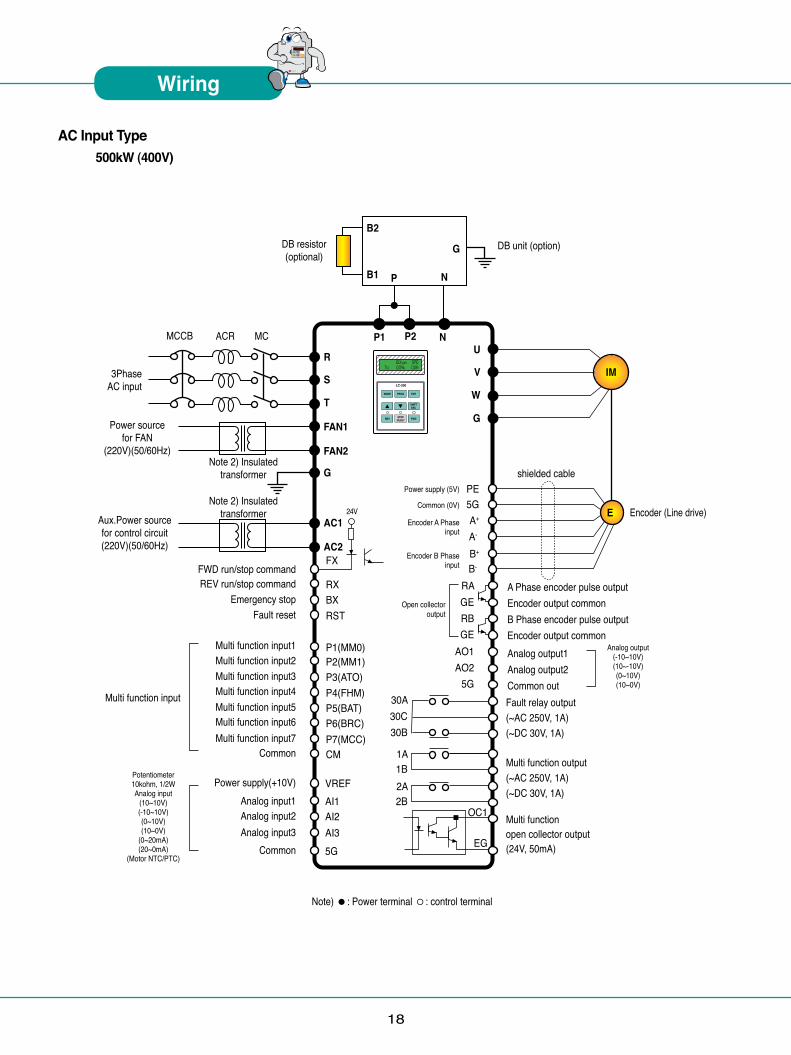
500kW (400V)
MCCB MC
3Phase AC input
Power source for FAN
(220V)(50/60Hz)
ACR
Multi function input1Multi function input2Multi function input3Multi function input4Multi function input5Multi function input6Multi function input7
Multi function input
Potentiometer10kohm, 1/2WAnalog input
(10~10V)(-10~10V)(0~10V)(10~0V)
(0~20mA)(20~0mA)
(Motor NTC/PTC)
Common
Power supply(+10V)Analog input1Analog input2Analog input3
Common
Analog output1Analog output2Common out
A Phase encoder pulse outputEncoder output commonB Phase encoder pulse outputEncoder output common
Multi function open collector output(24V, 50mA)
Multi function output(~AC 250V, 1A)(~DC 30V, 1A)
Fault relay output(~AC 250V, 1A)(~DC 30V, 1A)
Analog output(-10~10V)(10~-10V)(0~10V)(10~0V)
shielded cable
DB resistor(optional)
DB unit (option)
Encoder (Line drive)
R
S
T
FAN1
FAN2
G
AC1
AC2
U
V
W
G
P3(ATO)P4(FHM)P5(BAT)P6(BRC)P7(MCC)CM
P1(MM0)P2(MM1)
FX
RX BX RST
PE5GA+
A-
B+
B-
RAGERBGE
AO1AO2
5G30A30C30B
1A1B2A2B
OC1
EG
P1 P2
B2
B1 NP
G
N
IM
E
Note) ●: Power terminal ◦: control terminal
Note 2) Insulatedtransformer
Note 2) Insulatedtransformer
REV run/stop commandFWD run/stop command
Emergency stopFault reset
VREFAI1AI2AI35G
Open collector output
AC Input Type
24V
Power supply (5V)
Common (0V)
Encoder A Phase input
Encoder B Phase input
Aux.Power sourcefor control circuit(220V)(50/60Hz)
Wiring
� � � � �� �
19
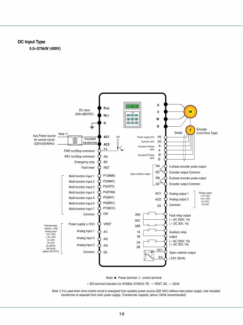
5.5~375kW (400V)
ïï
FWD run/Stop commandREV run/Stop command
Emergency stopFault reset
Multi-function input 1Multi-function input 2 Multi-function input 3 Multi-function input 4 Multi-function input 5 Multi-function input 6 Multi-function input 7
Common
Power supply (+10V)
Analog input 1
Analog input 2
Analog input 3
Common
Power supply (5V)
Common (0V)
Encoder A Phase input
Encoder B Phase input
Open collector output
DC input(540~680VDC)
P(+)
AC1
AC2
N(-)
G
U
V
W
G
24V
FX
RX BX RST
PE5GA+
A-
B+
B-
P3(ATO)P4(FHM)P5(BAT)P6(BRC)P7(MCC)CM
P1(MM0)P2(MM1)
VREF
AI1
AI2
AI3
5G
RA
GE
RB
GE
AO1AO2
5G
30A
30C30B
1A1B2A2B
OC1
EG
A phase encoder pulse outputEncoder output CommonB phase encoder pulse outputEncoder output Common
ShieldEncoder(Line Drive Type)
Analog output 1Analog output 2Common
Fault relay output( ~ AC 250V, 1A)( ~ DC 30V, 1A)
Auxiliary relay output( ~ AC 250V, 1A)( ~ DC 30V, 1A)
Open collector output( 24V, 50mA)
IM
E
DC Input Type
Note) ●: Power terminal ◦: control terminal
Note 1) It is used when drive control circuit is energized from auxiliary power source (220 VAC) without main power supply. Use insulated transformer to separate from main power supply. (Transformer capacity: above 100VA recommended)
�SIO terminal indication for SV2800~3750iV5: PE � PENT, GE � G24X
Analog output(-10~10V)(10~-10V)(0~10V)(10~0V)
Potentiometer10kohm, 1/2WAnalog input(10~-10V)(-10~10V)(0~10V)(10~0V)
(0~20mA)(20~0mA)
(Motor NTC/PTC)
Aux.Power sourcefor control circuit(220V)(50/60Hz)
Note 1)Insulated
transformer

20
Note 1)Insulated
transformer
500kW (400V)
ÔÔ
FWD run/Stop commandREV run/Stop command
Emergency stopFault reset
Multi-function input 1Multi-function input 2 Multi-function input 3 Multi-function input 4 Multi-function input 5 Multi-function input 6 Multi-function input 7
Common
Power supply (+10V)
Analog input 1
Analog input 2
Analog input 3
Common
Power supply (5V)
Common (0V)
Encoder A Phase input
Encoder B Phase input
Open collector output
DC input(540~680VDC)
P(+)
AC1
FAN1
FAN2
AC2
N(-)
G
U
V
W
G
24V
FX
RX BX RST
PE5GA+
A-
B+
B-
P3(ATO)P4(FHM)P5(BAT)P6(BRC)P7(MCC)CM
P1(MM0)P2(MM1)
VREF
AI1
AI2
AI3
5G
RA
GE
RB
GE
AO1AO2
5G
30A
30C30B
1A1B2A2B
OC1
EG
A phase encoder pulse outputEncoder output CommonB phase encoder pulse outputEncoder output Common
ShieldEncoder(Line Drive Type)
Analog output 1Analog output 2Common
Fault relay output( ~ AC 250V, 1A)( ~ DC 30V, 1A)
Auxiliary relay output( ~ AC 250V, 1A)( ~ DC 30V, 1A)
Open collector output( 24V, 50mA)
IM
E
DC Input Type
Note) ●: Power terminal ◦: control terminal
Analog output(-10~10V)(10~-10V)(0~10V)(10~0V)
Potentiometer10kohm, 1/2WAnalog input(10~-10V)(-10~10V)(0~10V)(10~0V)
(0~20mA)(20~0mA)
(Motor NTC/PTC)
Aux.Power sourcefor control circuit(220V)(50/60Hz)
FAN and MC Power
(220V)(50/60Hz)
WarningInsulated
transformer
Wiring
� � � � �� �
Note 1) It is used when drive control circuit is energized from auxiliary power source (220 VAC) without main power supply. Use insulated transformer to separate from main power supply. (Transformer capacity: above 100VA recommended)
Warning) It must be energized AC220V (50/60Hz) to terminal of FAN1 and FAN2 because 30 ~ 500kW-4DC series have a cooling fan for AC power drive and MC. If not, Trip (30~160kW: “FAN/MC PWR”, 220kW: “FAN PWR”) will be occurred. The drive is not operated unless trip is released after AC220V inputs. The recommended order of power input and cutoff is as shown below. (The order of power On: 220VAC � P(+)/N(-) � Run, The order of power Off: Stop � P(+)/N(-) � 220VAC)
21
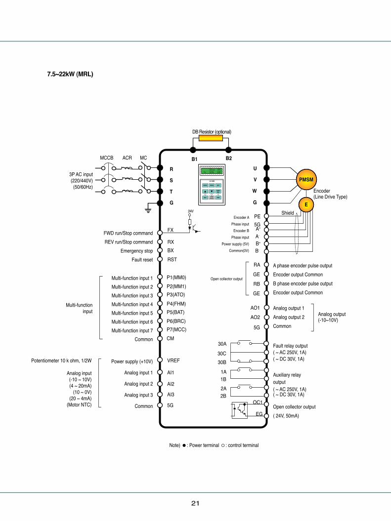
7.5~22kW (MRL)
Multi-functioninput
Potentiometer 10 k ohm, 1/2W
Analog input(-10 ~ 10V)(4 ~ 20mA)
(10 ~ 0V)(20 ~ 4mA)
(Motor NTC)
Note) ●: Power terminal ◦: control terminal
DB Resistor (optional)
B1 B2MCCB
FWD run/Stop commandREV run/Stop command
Emergency stopFault reset
Multi-function input 1Multi-function input 2 Multi-function input 3 Multi-function input 4 Multi-function input 5 Multi-function input 6 Multi-function input 7
Common
Power supply (+10V)
Analog input 1
Analog input 2
Analog input 3
Common
Encoder APhase input
Encoder BPhase input
Power supply (5V)Common(0V)
Open collector output
3P AC input(220/440V)
(50/60Hz)
ACR MC
R
S
T
G
U
V
W
G24V
FX
RX BX RST
PE5GA+
A-
B+
B-
P3(ATO)P4(FHM)P5(BAT)P6(BRC)P7(MCC)CM
P1(MM0)P2(MM1)
VREF
AI1
AI2
AI3
5G
RA
GE
RB
GE
AO1AO2
5G
30A
30C30B
1A1B2A2B
OC1
EG
A phase encoder pulse outputEncoder output CommonB phase encoder pulse outputEncoder output Common
Shield
Encoder(Line Drive Type)
Analog output 1Analog output 2Common
Fault relay output( ~ AC 250V, 1A)( ~ DC 30V, 1A)
Auxiliary relay output( ~ AC 250V, 1A)( ~ DC 30V, 1A)
Open collector output( 24V, 50mA)
Analog output(-10~10V)
PMSM
E
22
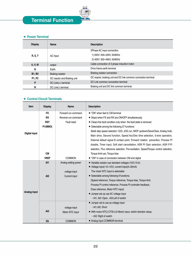
Terminal Function
� � � � �� �
Description
3Phase AC input connection 1) 200V: 200~230V, 50/60Hz 2) 400V: 300~460V, 50/60Hz Cable connection of 3 phase induction motor Drive frame earth terminal Braking resistor connection DC reactor, braking unit and DC link common connection terminalDC Link common connection terminal Braking unit and DC link common terminal
Name
AC Input
outputEarthBraking resistor DC reactor and Braking unit DC Link(+-) terminalDC Link(-) terminal
Display
R, S, T
U, V, WG
B1, B2P1, P2
PN
Item
Digital input
Analog input
Display
FXRX
RSTP1(MMO)
CMVREFAI1
AI2
AI3
5G
Name
Forward run commandReverse run command
Fault reset
COMMON Analog setting power
voltage inputCurrent input
voltage inputMotor NTC input
COMMON
Description
● "ON" when tied to CM terminal ● Stops when FX and RX are ON/OFF simultaneously ● Clears the fault condition only when the fault state is removed● Selectable among the following 27 functions:
(Multi step speed selection 1/2/3, JOG run, MOP up/down/Save/Clear, Analog hold, Main drive, Second function, Speed Acc/Dec time selection, 3-wire operation, External default signal B contact point, Forward rotation prevention, Process PI disable, Timer input, Soft start cancellation, ASR PI Gain selection, ASR P.PI selection, Flux reference selection, Pre-excitation, Speed/Torque control selection, Torque limit use, Torque bias
● "ON" in case of connection between CM and digital ● Variable resistor use standard voltage(+10V):10㏀ ● Voltage input(-10~10V), current input(4~20mA)
The motor NTC input is selectable ● Selectable among following 9 functions;
(Speed reference, Torque reference, Torque bias, Torque limit, Process PI control reference, Process PI controller feedback, Draw reference, Motor NTC input) ● Jumper set up use AC voltage input
→ AI1, AI2: Open , AI3:Left of switch ● Jumper set to use as voltage input
→ AI1,AI2: Short● With motor NTC( OTIS-LG Motor) input, switch direction setup
→ AI3: Right of switch ● Analog input COMMON terminal
■ Control Circuit Terminals
■ Power Terminal

23
■ Control Circuit Terminal Control Terminal Feature●Control Terminal Panel Arrangement(Standard Type(SIO) - Non insulated type)
Classification
Encoder Input
Encoder output
Analog Output
Digital Output
Display
PE5GA+A-
B+B-PE5GPAPBRAGERBGE
AO1
AO2
5G1A1B2A2B
OC1EG30A30B30C
Name
Encoder power
Encoder A phase signal
Encoder B phase signal
Encoder power
Encoder A phase signalEncoder B phase signalEncoder output-phase A
Encoder output common terminalEncoder output-phase B
Encoder output common terminal Analog output1
Analog output2
COMMON
Multi function digital output1(contact point A)
Multi function digital output2(contact point B)
Multi function open collector output
Fault signal A contact pointFault signal B contact point
COMMON
Description
+5V Line drive power(Jumper set required)0V
● A and B phase signals of line drive encoder● To use the line drive type encoder, the "P5 pin" of I/O PCB JP2 should be
shorted and then the JP1 switch should be pulled down to "LD" direction ● Jumper setup (factory default)
+15V Open collector power (Jumper setup is required) 0V
● A and B phase signals of complementary and open collector type signals ●Short the "P15 pin" of I/O PCB JP2 and then pull up the JP1 switch to "OC"
● Encoder phase A and B output signal (Open collector type)
● Output -10V~+10V● Selection among following 31 items;
(Motor speed, Speed reference1~2, Torque reference1~2,Torque current volume Flux reference, Flux reference volume, Drive output current, Drive output voltage, Motor temperature, DC voltage..)
● COMMON terminal for analog output
● Selectable among following 14 items; ( Zero speed detection, speed detection(polarity valid), speed detection(rotation direction invalid), Speed reach, Speed matching, arbitrary torque detection Torque limit feature, Motor overheating signal, Drive overheating signal, Low voltage feature, Drive run signal, Drive regeneration signal, Drive run function, Timer output)
● Activates when the faults occur● Not available in emergency stop● Common for A and B digital output
■ Control Circuit Terminals

24
I/O Board
� � � � �� �
1) Encoder wiring and Jumper setup (+15V Complementary or Open collector)
2) Encoder wiring and Jumper setup (+5V Line drive)
3) Analog Input Jumper setup (Voltage/ Current/ Motor NTC inputs)
● Do not change the jumper set for the encoder type during operation. The Jumper type change during operation results in a serious system damage. Jumpers should be set properly before the drive operation.● The NTC input of the analog input 3(AI3) is only available with OTIS-LG motors. Use of different type of NTC may cause the motor damage due to overheating.
Warning
I/O PCB version : V1.0 I/O PCB version : V2.0
I/O PCB version : V1.0 I/O PCB version : V2.0
I/O PCB version : V1.0 I/O PCB version : V2.0
25
� � � � �� �
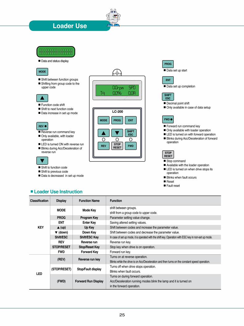
Loader Use
■Data and status display
■Data set up start
■Data set up completion
■Decimal point shift■Only available in case of data setup
■Forward run command key■Only available with loader operation■LED is turned on with forward operation■ Blinks during Acc/Deceleration of forward
operation
■Stop command■Available with the loader operation■ LED is turned on when drive stops its
operation■ Blinks when fault occurs■ Reset■ Fault reset
■Shift between function groups■ Shifting from group code to the
upper code
■Function code shift■Shift to next function code■ Data increase in set up mode
■Reverse run command key■ Only available, with loader
operation■LED is turned ON with reverse run■ Blinks during Acc/Deceleration of
reverse run
■Shift to function code■Shift to previous code■ Data is decreased in set up mode
Classification Display Function Name Function
MODE Mode Key shift between groups. shift from a group code to upper code. PROG Program Key Parameter setting value change. ENT Enter Key Saving altered setting values. KEY ▲ (up) Up Key Shift between codes and increase the parameter value. ▼ (down) Down Key Shift between codes and decrease the parameter value. Shift/ESC Shift/ESC Key In case of set up mode, it is operated with the shift key. Operation with ESC key in non-set up mode. REV Reverse run Reverse run key. STOP/RESET Stop/Reset Key Stop key when drive is on operation. FWD Forward Key Forward run key. Turns on at reverse operation. (REV) Reverse run key Blinks while the drive is on Acc/Deceleration and then turns on the constant speed operation. Turns off when drive stops operation. LED
(STOP/RESET) Stop/Fault display Blinks when fault occurs.
Turns on during forward operation. (FWD) Forward Run Display Acc/Deceleration running modes blink the lamp and it is turned on in the forward operation.
■Loader Use Instruction
26
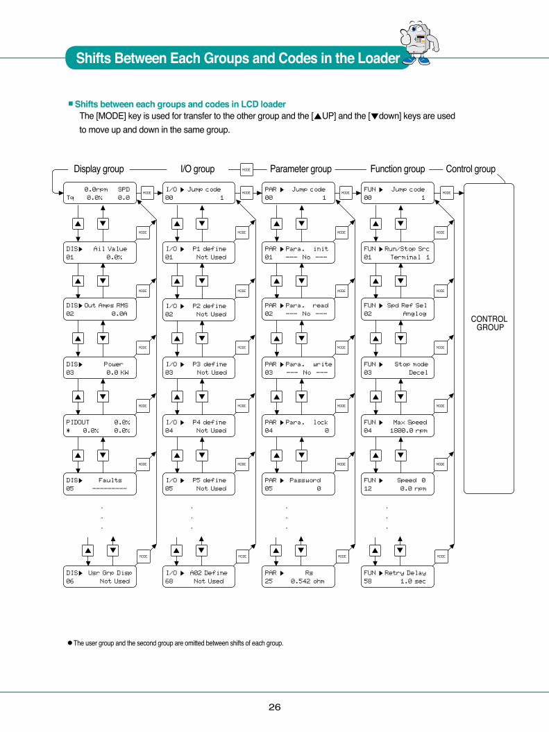
Shifts Between Each Groups and Codes in the Loader
� � � � �� �
■Shifts between each groups and codes in LCD loaderThe [MODE] key is used for transfer to the other group and the [▲UP] and the [▼down] keys are used to move up and down in the same group.
●The user group and the second group are omitted between shifts of each group.
Display group I/O group Parameter group Function group Control group

27
� � � � �� �
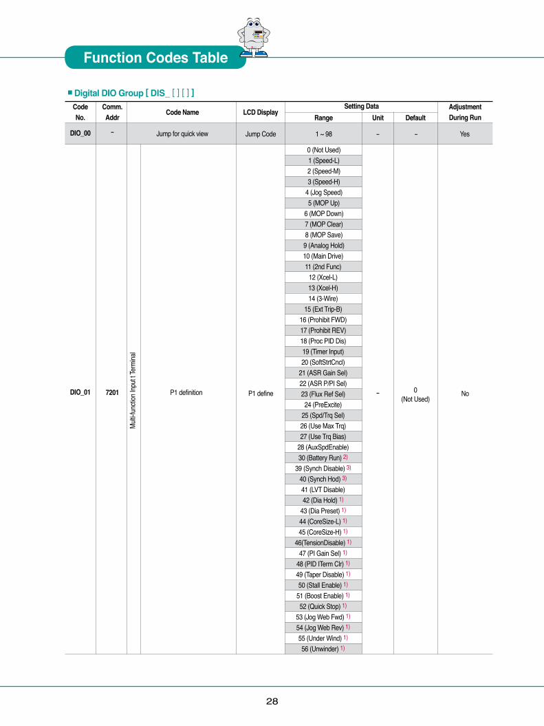
Function Codes Table
*Note 1) It is effective only when you use Extended I/O (EXTN_I/O). 2) It is displayed on WEB control Mode.
Comm.Addr
-
-
Code No.
DIS_00
DIS_01
DIS_02DIS_03
DIS_04
DIS_05DIS_06
--
-
-7106
User Display 2User Display 3
Process PID OutputRef / FB
Faulty DisplayDisplay Setting
Same as the range of ‘DIS_01’
PID Output*xx.x%
FaultsDisp 2 (Display ALL) Used
Yes
- - - -Yes
-
0.0%0.0%
DC Bus VoltTerminal In
-
YesYes-
Code Name
Motor Speed/Control ModeOutputTorque/Output Current
User Display 1
LCD Display
0.0rpm Tq 0.0% Ai1 ValueAi2 ValueAi3 Value
Ai4 Value 1)Ai5 Value 1)
PreRamp RefPostRamp RefASR Inp RefMotor SpeedMotor SpdEstSpeed DevASR Out
Torque BiasPosTrq LimitNegTrq LimitRegTrq LimitTorque Ref
IqeRefIqe
Flux RefIde Ref
IdeACR_Q OutACR_D Out
VdeRefVqeRef
Out Amps RMSOut Volt RMS
PowerDC Bus VoltProc PI RefProc PI F/BProc PI Out
MotTemp NTCInv Temp
Inv i2tMP OutputCtrl Mode
S/W VersionRun TimeTerminal In
Terminal OptTerminal OutRun StatusDiameter 2)
Line SPD CMD 2)Reel SPD 2)PhInOpenLvl
Setting DataRange Default
-
PreRampRef
AdjustmentDuring Run 1)
-
Yes
■Display Group [ DIS_ [ ] [ ] ]
UnitSPD0.0A%%%%%
rpmrpmrpmrpmrpmrpm%%%
- %%%AA%AAVVVVAV
kWV%%%
degdeg%%-------%%%V
* ‘ – ‘ mark of communication adrress indicates communication exclusion.* Setting during Drive operation (Yes : possible, No : impossible)
-
28
� � � � �� �
Function Codes Table
Multi-
functi
on In
put t
Term
inal
Comm.Addr
-
7201
Code No.
DIO_00
DIO_01
Code Name
Jump for quick view
P1 definition
0 (Not Used) 1 (Speed-L) 2 (Speed-M) 3 (Speed-H)
4 (Jog Speed) 5 (MOP Up)
6 (MOP Down) 7 (MOP Clear) 8 (MOP Save)
9 (Analog Hold)10 (Main Drive)11 (2nd Func)
12 (Xcel-L)13 (Xcel-H)14 (3-Wire)
15 (Ext Trip-B)16 (Prohibit FWD)17 (Prohibit REV)18 (Proc PID Dis)19 (Timer Input)20 (SoftStrtCncl)
21 (ASR Gain Sel)22 (ASR P/PI Sel)23 (Flux Ref Sel)24 (PreExcite)
25 (Spd/Trq Sel)26 (Use Max Trq)27 (Use Trq Bias)
28 (AuxSpdEnable)30 (Battery Run) 2)
39 (Synch Disable) 3)
40 (Synch Hod) 3)
41 (LVT Disable)42 (Dia Hold) 1)
43 (Dia Preset) 1)
44 (CoreSize-L) 1)
45 (CoreSize-H) 1)
46(TensionDisable) 1)
47 (PI Gain Sel) 1)
48 (PID ITerm Clr) 1)
49 (Taper Disable) 1)
50 (Stall Enable) 1)
51 (Boost Enable) 1)
52 (Quick Stop) 1)
53 (Jog Web Fwd) 1)
54 (Jog Web Rev) 1)
55 (Under Wind) 1)
56 (Unwinder) 1)
Setting DataLCD Display
Range Default
0(Not Used)
AdjustmentDuring Run
No
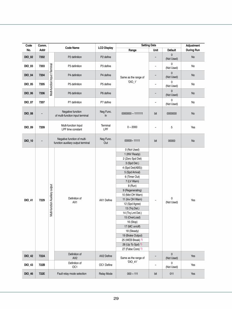
■Digital DIO Group [ DIS_ [ ] [ ] ]
Unit
Jump Code
P1 define
1 ~ 98 -
-
- Yes
29
Multi-
functi
on In
put t
Term
inal
Multi-
functi
on Au
xiliar
y outp
utComm.Addr
Code No. Code Name
Same as the range of ‘DIO_1’
0000000 ~ 1111111
0 ~ 2000
00000~ 11111
0 (Not Used)1 (INV Ready)
2 (Zero Spd Det)3 (Spd Det.)
4 (Spd Det(ABS))5 (Spd Arrival)6 (Timer Out)7 (LV Warn)
8 (Run)9 (Regenerating)
10 (Mot OH Warn)11 (Inv OH Warn)12 (Spd Agree)13 (Trq Det.)
14 (Trq Lmt Det.)15 (OverLoad)
16 (Stop)17 (MC on/off)
18 (Steady)19 (Brake Output)25 (WEB Break) 1)
26 (Up To Spd) 1)
27 (False Core) 1)
Setting DataLCD Display
Range DefaultAdjustmentDuring Run Unit
0 (Not Used)
0 (Not Used)
0 (Not Used)
0 (Not Used)
0 (Not Used)
0 (Not Used)
P2 definition P2 define No-
P3 definition P3 define No-
P4 definition P4 define No-
P5 definition P5 define No-
P6 definition P6 define No-
P7 definition
Negative functionof multi-function input terminal
Multi-function Input LPF time constant
Negative function of multi-function auxiliary output terminal
Definition of AX1
Definition of AX2 Same as the range of
‘DIO_41’Definition of OC1
Fault relay mode selection
0 (Not Used)
0 (Not Used)
0 (Not Used)
P7 define
Neg Func. In
Terminal LPF
Neg Func. Out
No
No
Yes
No
Yes
Yes
Yes
Yes
-
bit
-
bit
-
-
-
bit 011
AX1 Define
AX2 Define
OC1 Define
Relay Mode 000 ~ 111
0000000
5
00000
DIO_02 7202
DIO_03 7203
DIO_04 7204
DIO_05 7205
DIO_06 7206
DIO_07
DIO_08
DIO_09
DIO_10
DIO_41
DIO_42
DIO_43
DIO_46
7207
-
7209
-
7229
722A
722B
722E

30
� � � � �� �
Function Codes Table
Comm.Addr
Code No. Code Name
0.1 ~ 10.0-3600 ~ 3600
0.1 ~ 10.0
0.0 ~ 250.00.1 ~ 10.0
0.1 ~ 3600.00.1 ~ 3600.0
30 ~ 2500 ~ 30
0 (No) / 1 (Yes)30 ~ 2500 ~ 6050 ~ 850 ~ 10
75 ~ 1300 ~ 10
1 ~ 2500 (1200)1 (2400)2 (4800)3 (9600)4 (19200)5 (384000)0 (None)
1 (FreeRun)2 (Stop)10 ~ 300
Setting DataLCD Display
Range DefaultAdjustmentDuring Run Unit
ZSD Level 0.0 ~ 480.0 YesrpmZSD BandSD LevelSD BandSA Band
SEQ BandTD LevelTD Band
TimerOn DlyTimerOff Dly
OL LevelOL Time
OLT SelectOLT LevelOLT Time
TempIH Warn Band
MH Warn TempMH Warn Band
Inv Number
YesYes
Yes
YesYesYesYesYesYesYesYesYesYesYesYesYes
No
%rpm
%
%%
secsec%
sec-%
secdegdegdegdeg
Zero speed detection levelZero speed detection band
Speed detection levelSpeed detection band
Speed arrival bandSpeed deviation bandTorque detection levelTorque detection bandTimer On delay timeTimer Off delay time
warning temp.Drive overheat warning bandMotor overheat warning temp.Motor overheat warning band
Drive station address
Warning levelWarning timeTrip selection
Trip levelTrip time
MC ON delay time 4)
MC OFF delay time 4)
485 BaudRate
How to Run at Lost command
4)
MC Timer Off 100 ~ 50000 msec 1000 No
MC Timer Off
485 BaudRate
Lost Command
Timer
100 ~ 50000 msec
bps
-
sec
9600
0 (None)
No
No
No
No10
10.00.50
0.5
0.00.50.10.115010
1 (Yes)18060755
1205
1
DIO_47 722FDIO_48DIO_49DIO_50DIO_51DIO_52DIO_53DIO_54DIO_55DIO_56DIO_57DIO_58DIO_59DIO_60DIO_61DIO_62DIO_63DIO_64DIO_65
DIO_95
7230723172327233723472357236723772387239723A723B723C723D723E723F72407241
725F
DIO_67
DIO_68
DIO_96
DIO_97
DIO_98
7243
7244
7260
7261
7262
Overl
oad
1000
*Note 1) Displayed WEB Control mode setting. 2) It can be set at 5.5 ~ 22 kW-2/4 class. 3) It will be displayed as CON_02 sets to ‘Synchro’ when Synchronization option board is installed. 4) It will be displayed when the definition of multi-funtion output sets as ‘MC On/Off’. 5) It will be displayed RS-485 communication option board is installed. Refer to the user manual for RS485/Modbus-RTU option board (iP5A/iV5).
31
Enco
der
Motor
Comm.Addr
Code No. Code Name
1 ~ 38
0.7 ~ 500.00 (Self-cool)
1 (Forced-cool)360 ~ 4096
0 (A Phase Lead)1 (B Phase Lead)0 (No) / 1 (Yes)
0 ~ 1000.00 ~ 10.000.0 ~ 50.0
100.0 ~ 3600.0120 ~ 560
2 ~ 1270.0 ~ 100.0
10 ~ 2501.0 ~ 1000.0170 ~ 230320 ~ 480
0 (Rotational) 1 (Standstill)
0 (No)2 (DIS)4 (PAR)6 (CON)8 (AIO)
10 (2ND)12 (SYN)14 (SLS)
0 (2.2)2 (5.5)4 (11.0)6 (18.5)8 (30.0)10 (45.0)12 (75.0)14 (110.0)16 (160.0)18 (280.0)20 (375.0)
0 (No)2 (DIS)4 (PAR)6 (CON)8 (AIO)
10 (2ND)12 (SYN)14 (SLS)
1 (3.7)3 (7.5)5 (15.0)7 (22.0)9 (37.0)11 (55.0)13 (90.0)15 (132.0)17 (220.0)19 (315.0)
Setting DataLCD Display
Range DefaultAdjustmentDuring Run Unit
Yes- -
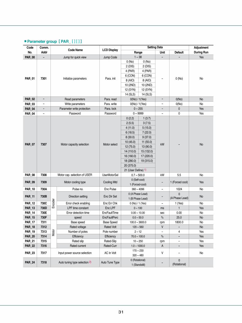
Initialize parameters
Jump for quick view
Para. init
Jump Code
No0 (No)-
Read parametersWrite parameters
Parameter write protectionPassword
Para. readPara. writePara. lockPassword
0(No) / 1(Yes)0(No) / 1(Yes)
0 ~ 2550 ~ 9999
0(No)0(No)
00
NoNoYesYes
Motor capacity selection
Motor cap. selection of USER
Motor cooling type
Input power source selection
Auto tuning type selection 2)
Direction setting
Pulse no.
Error check enablingLPF time constant
Error detection timespeed
Base speedRated voltage
Number of polesEfficiencyRated slip
Rated current
Enc Pulse
Enc Err ChkEnc LPF
EncFaultTimeEncFaultPercBase SpeedRated Volt
Pole numberEfficiencyRated-SlipRated-Curr
Motor select No
No
Yes
kW
kW
-
21 (User Define) 1)
UserMotorSel
Cooling Mtd
Enc Dir Set
AC In Volt
Auto Tune Type
-
5.5
No- 1024
NoV -
NoYesNoNoNoNoYesYesYesYes
-mssec%
rpmV-%
rpmA
1 (Yes)1
0.0025.0
1800.0-4---
No-0
(A Phase Lead)
-0
(Rotational)
1 (Forced cool)
PAR_01
PAR_00
7301
-
PAR_02PAR_03PAR_04PAR_04
PAR_07
PAR_08
PAR_10
PAR_12PAR_13PAR_14PAR_15PAR_17PAR_18PAR_19PAR_20PAR_21PAR_22
----
----
7307
7308
730A
730C730D730E730F731173127313731473157316
■Parameter group [ PAR_ [ ] [ ] ]
7309
730B
7317
7318
PAR_09
PAR_11
PAR_23
PAR_24

32
� � � � �� �
Function Codes Table
Comm.Addr
Code No. Code Name
NoneALL1/ALL2
Encoder TestRs Tuning
LsigmaFlux CurrLs TuningTr Tuning
Inertia Tuning 4)10.0 ~ 100.0
70% to 0.0 ~ PAR_22 30 ~ 3000
0.00 ~ 500.000.00 ~ 100.000.000 ~ 5.000
x1 / x16 / x32 / x640 (No) / 1 (Yes)0.001 ~ 60.0000.500 ~ 10.0000.010 ~ 50.000
Setting DataLCD Display
Range DefaultAdjustmentDuring Run Unit
Auto Tuning
Tune TorqueFlux-Curr
TrLs
LsigmaRs
Enc ScaleInertia Tune
InertiaJ Spd TimeInertia LPF
No
YesYesYesYesYesYesNoNoYesNoNo
-
%A
msmHmHohm--
kg·m2
secms
Auto tuning range setting 2)
Tuning Torque
Encoder pulse multiplication 3)
Selection for motor inertia tuningFactor of motor inertia
Acc./Dec. time of Inertia tuningInertia LPF
Motor flux currentMotor time constantLeakage inductanceLeakage coefficientStator resistance
None
70-----
x 10 (No)
-0.5000.100
PAR_25
PAR_26PAR_27PAR_28PAR_29PAR_30PAR_31PAR_34PAR_35PAR_36PAR_37PAR_38
731A731B731C731D731E731F73227323732473257326
Motor
*Note 1) When PAR_07 is set to “User Define”, PAR_08 will be displayed. 2) If PAR_24 (Auto-tuning type selection) is set to No.1 “Standstill”, the order of display in PAR_25 (Auto-tuning range setting) will be None ⇒ ALL ⇒ Rs Tuning ⇒ Lsigma ⇒ If/Tr/Ls Tune. 3) Caution: PAR_33 (Enc Scale) Code is necessary only in the case of installation of SIN/COS Encoder option board, Don’t modify the default value “X1” when not using SIN/COS Encoder board If you modify the value, the normal operation isn’t possible. For any extra information in detail, refer to the option dedicated manual. 4) It will be displayed when PAR_35(Selection for motor inertia tuning) sets as ‘Yes’.

33
Multi-
step s
peed
Comm.Addr
Code No. Code Name
1 ~ 85
400.0 ~ 3600.00.0 ~ 500.0
0.0 ~ Max Speed
0.00 ~ 100.000 (Max Speed)1 (Ref Speed)
0.0 ~ 50.0
0 (0.01 sec)1 (0.1 sec)
0.00 ~ 6000.0
0 (Terminal 1)1 (Terminal 2)
2 (Keypad)3 (Option)0 (Analog)
1 (Keypad1)2 (Keypad2)3 (Option)
6 (Line SPD Ref) 1)
7 (Line SPD Opt) 1)
Setting DataLCD Display
Range DefaultAdjustmentDuring Run Unit
Yes- -Jump for quick view Jump Code
Max. motor speedMin. motor speed
JOG speedDwell SpeedDwell Time
01234567
Max SpeedMin Speed 2)
Speed 0Speed 1Speed 2Speed 3Speed 4Speed 5Speed 6Speed 7
Jog SpeedDwell SpeedDwell Time
1800.00.00.00.00.00.00.00.00.00.0
100.0100.00.00
NoNoYesYesYesYesYesYesYesYesYesNoNo
FUN_00
RUN/STOP commandsource selection
0 (Decel)1 (Free-run)
Run/Stop Src No
No
No
0 (Terminal 1)
1 (Keypad1)
0 (Decel)
-
-
-
rpm
sec
-
-
sec
%
FUN_01 7401
-
FUN_02
FUN_03
FUN_04FUN_05FUN_12FUN_13FUN_14FUN_15FUN_16FUN_17FUN_18FUN_19FUN_20FUN_21FUN_22
FUN_41FUN_42FUN_43FUN_44FUN_45FUN_46FUN_47FUN_48
FUN_51FUN_52FUN_53
-
7403
74047405740C740D740E740F7410741174127413741474157416
7429742A742B742C742D742E742F7430
743374347435
■Function group [ FUN_ [ ] [ ] ]
Speed setting source selection
Stop mode selection
Spd Ref Sel
NoAcc./Dec. reference Speed0
(Max Speed)FUN_33 7421 Acc/Dec Ref
NoS ratio 1 in acceleration start
Acceleration time 1Deceleration time 1Acceleration time 2Deceleration time 2Acceleration time 3Deceleration time 3Acceleration time 4Deceleration time 4
Dec.time of zero speedDec. time of emergent stop
Initial excitation time of motor
Acc Time-1Dec Time-1Acc Time-2Dec Time-2Acc Time-3Dec Time-3Acc Time-4Dec Time-4
0 Dec TimeBX Time
PreExct Time
2.00 2)
2.00 2)
3.00 2)
3.00 2)
4.00 2)
4.00 2)
5.00 2) 5.00 2)
0.000.00
YesYesYesYesYesYesYesYes
YesYesNo
0.0FUN_36 7424 Acc S Start
No0.0FUN_37 7425 Acc S End
No0.0FUN_38 7426 Dec S Start
No0.0FUN_39 7427 Dec S End
No
Yes
0.0
0 (No)
FUN_40
FUN_49
7428
7431
Time scale
Use 0 Dec T 0 (No) / 1 (Yes)
0.00 ~ 6000.00.0 ~ 6000.00 ~ 10000
secsecms
Stop mode
S ratio 2 in acceleration start
S ratio 1 in acceleration start
S ratio 2 in acceleration start
Selection about use of zero speed time
Time scale of acc./dec. time
34
� � � � �� �
Function Codes Table
Comm.Addr
Code No. Code Name
100 ~ 100000 (No) / 1 (Yes)FUN_56 ~ 20050 ~ FUN_55
(Only available to 150%)
0 (No) / 1 (Yes)0 (No) / 1 (Yes)
0 ~ 100.0 ~ 60.0
0.00 ~ 10.00100.0 ~ 130.00.00 ~ 2.000.00 ~ 30.000.0 ~ 500.00.0 ~ 150.00.00 ~ 30.000.0 ~ 500.0
0 (No) / 1 (Yes)600(300) ~ 800(400)
0.0 ~ 500.00.0 ~ 300.020 ~ 300002.5 ~ 200.0
12 ~ PAR_180 (No) / 1 (Yes)
2.0 ~ 100.00 (No) / 1 (Yes)
0.0~500.00 ~ 1
0.00 ~ 600.000.00 ~ 600.000(Absolute)1(Relative)
Setting DataLCD Display
Range DefaultAdjustmentDuring Run Unit
Open Time 6)
Open Speed 6)
Open Current 6)
Close Time 6)
Close Speed 6)
Run selectionRun voltage level 7)
Speed limitation 7)
Speed P gain 7)
Speed I gain 7)
Hold TimeETH SelectETH 1 min
Power-on RunRST Restart
Retry NumberRetry Delay
Restart Time 5)
OverSpdLevelOverSpd TimeBKOpen TimeBKOpen SpdRelease CurrBKClose TimeBKClose SpdRegenAvd SelRegenAvd LvlCompFreq LmtRegenAvd PRegenAvd IBatt. Speed
Batt. VoltPhInOpenChkPhInOpenLvl
PhOutOpenChkAuxSpeedMaxAuxSpeedType
AuxAccTimeAuxDecTime
AuxSpeedMode
10000 (No)150
0 (No)0 (No)
01.00.00120.00.000.000.020.00.000.0
0 (No)700(350)
100.050.050050.048
1 (Yes)3.0
1 (Yes)10.0
02.002.00
0(Absolute)
ms-%
---
secsec%
secsecrpm%
secrpm-V
rpm%msrpmV-V-
rpm-
secsec
-
NoYesYes
YesYesYesYesNoNoNoNoNoNoNoNoNoNoNoYesYesNoNoNoYesNoYesNoNoNo
No
%
FUN_54FUN_55FUN_56
FUN_59FUN_60FUN_61FUN_62FUN_63FUN_64FUN_65FUN_66FUN_67FUN_68FUN_69FUN_70FUN_71FUN_72FUN_73FUN_74FUN_75FUN_76FUN_77FUN_78FUN_79FUN_80FUN_81FUN_82FUN_83FUN_84
FUN_85
743674377438
743B743C743D743E743F7440744174427443744474457446744774487449744A744B744C744D744E745074517452745374547455
7456
FUN_33
FUN_58
7439
743A
ETH Cont
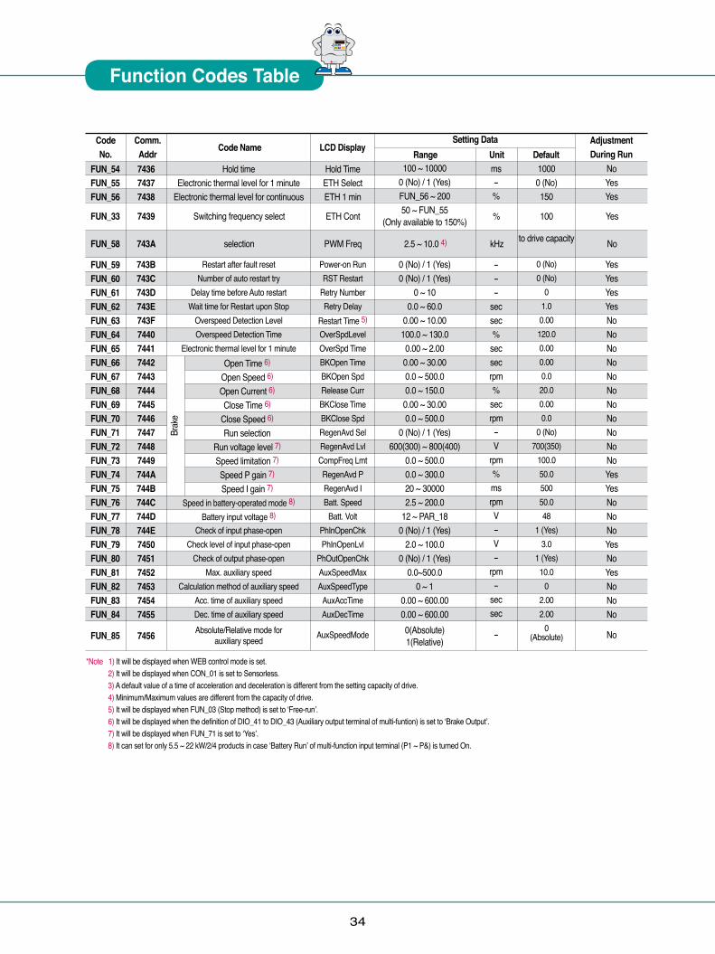
PWM Freq kHz Noto drive capacity2.5 ~ 10.0 4)
Yes
Hold timeElectronic thermal level for 1 minute
Electronic thermal level for continuous
Restart after fault resetNumber of auto restart try
Delay time before Auto restartWait time for Restart upon Stop
Overspeed Detection LevelOverspeed Detection Time
Electronic thermal level for 1 minute
Speed in battery-operated mode 8)
Battery input voltage 8)
Check of input phase-openCheck level of input phase-open
Check of output phase-openMax. auxiliary speed
Calculation method of auxiliary speedAcc. time of auxiliary speed Dec. time of auxiliary speed Absolute/Relative mode for
auxiliary speed
100
Brak
e
Switching frequency select
selection
*Note 1) It will be displayed when WEB control mode is set. 2) It will be displayed when CON_01 is set to Sensorless. 3) A default value of a time of acceleration and deceleration is different from the setting capacity of drive. 4) Minimum/Maximum values are different from the capacity of drive. 5) It will be displayed when FUN_03 (Stop method) is set to ‘Free-run’. 6) It will be displayed when the definition of DIO_41 to DIO_43 (Auxiliary output terminal of multi-funtion) is set to ‘Brake Output’. 7) It will be displayed when FUN_71 is set to ‘Yes’. 8) It can set for only 5.5 ~ 22 kW/2/4 products in case ‘Battery Run’ of multi-function input terminal (P1 ~ P&) is turned On.
35
Comm.Addr
Code No. Code Name
1 ~ 801 (Speed)2 (Torque)
3 (Sensorless)General VectElevator 1)
Synchro 2)
WEB Control0.1 ~ 200.00 ~ 500000 ~ 200000.1 ~ 200.00 ~ 500000 ~ 2000010 ~ 10000
-100.0 ~ 100.00.00 ~ 600.00.0 ~ 999.90.0 ~ 100.00.0 ~ 100.0
-100.0 ~ 100.0-100.0 ~ 100.0
0 ~ 500-250.0 ~ 250.00 (Base Speed)1 (Ref Speed)2 (SpeedSet)
1.00 ~ FUN_040 (Disable)1 (Enable)
2 (Terminal)0 ~ 10000
-100.0 ~ 100.00.0 ~ 100.0
0(Base Spd)/1(Ref Spd)
0.00 ~ 600.00.0 ~ 3600.00.0 ~ 100.00 (None)
1 (Analog)2 (Keypad)3 (Option)
-180.0 ~ 180.0
Setting DataLCD Display
Range DefaultAdjustmentDuring Run Unit
Yes- -Jump for quick view Jump Code
P Gain 1I Gain 1
LPF time constant 1P Gain 2I Gain 2
LPF time constant 2Ramp time for ASR gain
Reference (Loader)Ramp time
P gainI gainD gain
Positive limitNegative limit
Output LPF time constantOutput gain
Type selection
Speed Set setting 3)
Output Enable
Hold Time
Control quantity
Ramp timeMinimum speedMinimum torque
Reference (keypad)
ASR P Gain1ASR I Gain1ASR LPF1
ASR P Gain2ASR I Gain2ASR LPF2ASR RAMP
Proc PID RefPID Ramp
Proc PID KpProc PID Ki
PROC PID KdProc Pos LmtProc Neg LmtProc Out LPFProc OutGain
Proc PID Src
PID SpeedSet
Proc PID Enb
PIDHoldTimeDraw %Droop %
Droop TimeDroop MinSpdDroop MinTrq
Torque Ref
50.03000
5.03000
01000
0.00.000.00.00.01001000
0.0
100.0
10000.00.01
(Ref Speed)2.000.00.0
0.0
%msms%msmsms
%sec%%%%%ms%
rpm
-
ms%%
secrpm%
%
YesYesYesYesYesYesYes
YesNoYesYesYesYesYesYesYes
No
No
No
NoYesYes
YesYesYes
Yes
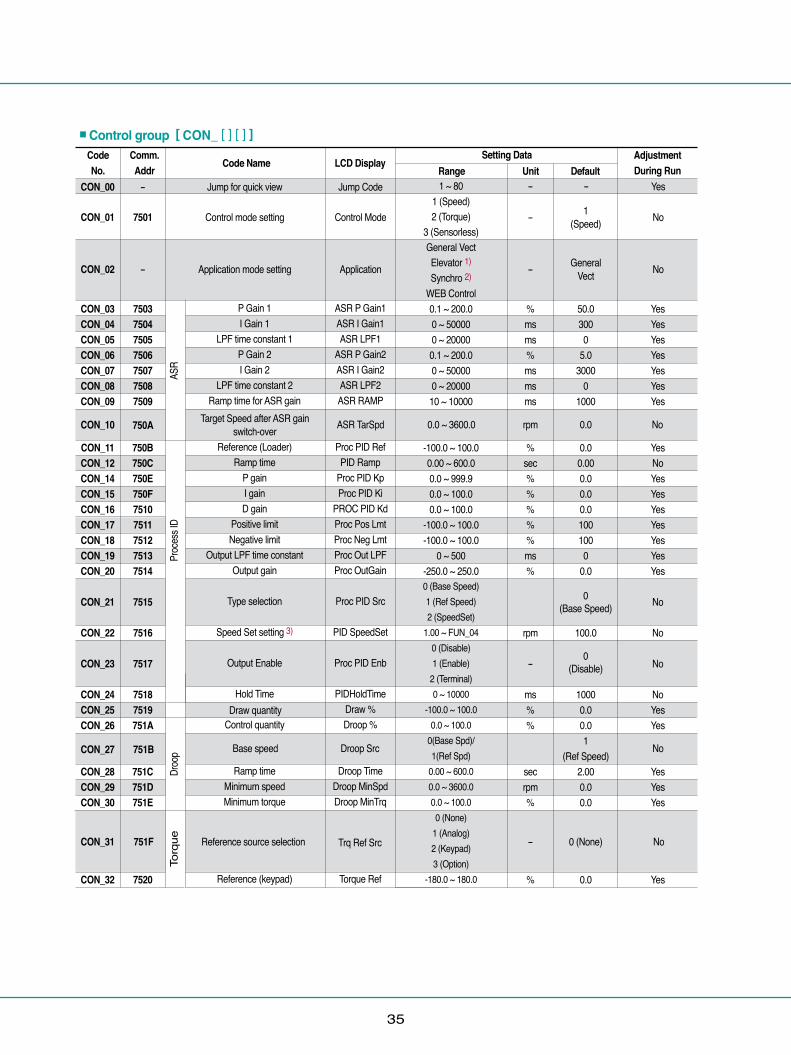
CON_00
Control mode setting
Application mode setting
Control Mode
Application
ASR TarSpd 0.0 ~ 3600.0
No
No
1 (Speed)
General Vect
-
-
- 0 (None) No
rpm 0.0 No
CON_01
CON_02
CON_10
7501
750A
-
-
CON_03CON_04CON_05CON_06CON_07CON_08CON_09
CON_11CON_12CON_14CON_15CON_16CON_17CON_18CON_19CON_20
CON_21
CON_22
CON_23
CON_24CON_25CON_26
CON_28CON_29CON_30
CON_32
7503750475057506750775087509
750B750C750E750F75107511751275137514
7515
7516
7517
75187519751A
751C751D751E
7520
■Control group [ CON_ [ ] [ ] ]
ASR
Proc
ess I
D Dr
oop
Torq
ue
Target Speed after ASR gain switch-over
CON_31
CON_27
751F
751B
Reference source selection
Draw quantity
Base speed
0 (Base Speed)
0 (Disable)
Trq Ref Src
Droop Src No

36
� � � � �� �
Function Codes Table
Comm.Addr
Code No. Code Name
0 (Kpd Kpd Kpd)1 (Kpd Kpd Ax)2 (Kpd Ax Kpd)3 (Kpd Ax Ax)
4 (Ax Kpd Kpd)5 (Ax Kpd Ax)6 (Ax Ax Kpd)7 (Ax Ax Ax)
8 (Opt Opt Opt)
0.0 ~ 250.0
0 (None)1 (Analog)2 (Keypad)3 (Option)
0.0 ~ 100.00000 ~ 1111 (Bit setting)
10 ~ 600001.0 ~ 300.01.0 ~ 300.00.1 ~ 300.0
100.0 ~ Max Speed
Setting DataLCD Display
Range DefaultAdjustmentDuring Run Unit
Limit source selection
Limit in forward runLimit in reverse runLimit in regeneration
Bias quantityBias feedforwardBalance quantity
Speed Search selectionSpeed Search time 4)
Speed Search P gain 4)
Speed Search I gain 4)
Speed Search LPF 4)
Speed bias of speed / torque
Trq Lmt Src
Pos Trq LmtNeg Trq LmtReg Trq Lmt
Trq BiasTrq Bias FFTrq Balance
Speed SearchSS Time
SS P GainSS I GainSS LPF
SpdLmtBias
150.0
0.00.050.00100300
100.0100.033.3
100.0
-
%
%-
ms%%ms
rpm
Yes
YesYesYesNoNoYesYesYes
No
CON_33
CON_34CON_35CON_36
CON_38CON_39CON_40CON_54CON_75CON_76CON_77CON_78
CON_80
7521
752275237524
7526752775287536754B754C754D754E
7550
Spee
d Sea
rchTo
rque
0 (Kpd Kpd Kpd) No
Trq Bias SrcCON_37
CON_79
7525
754F
Bias source selection
Speed limit of Speed /Torque switch-over
-150.0 ~ 150.0-150.0 ~ 150.0
0 (None)-
%%
No
Spd Lmt Src 0.1 ~ Max Speed rpm 1800.0 No
*Note 1) It will be displayed only when the E/L_IO board is installed. 2) It will be displayed only when the SYNC_IO board is installed. 5) It will be displayed when CON_21 (Process PID type) is set to SpeedSet. 6) It will be displayed when CON_01 is set to Sensorless.
Comm.Addr
Code No. Code Name
1 ~ 67
No / YesNo / Yes
-
Setting DataLCD Display
Range DefaultAdjustmentDuring Run Unit
Select Code numberInitialize to the initial value adequate
to the applicationUser data save
Recall saved User Data.User Group Data
Jump Code
User SaveUser RecallUser Grp
-User
DefineNoNo-
-
---
Yes
NoNoNo
USR_00
USR_02USR_03USR_04
-
---
USR_01 - Macro Init User Define E/L - No
■User group [ USR_ [ ] [ ] ]
37
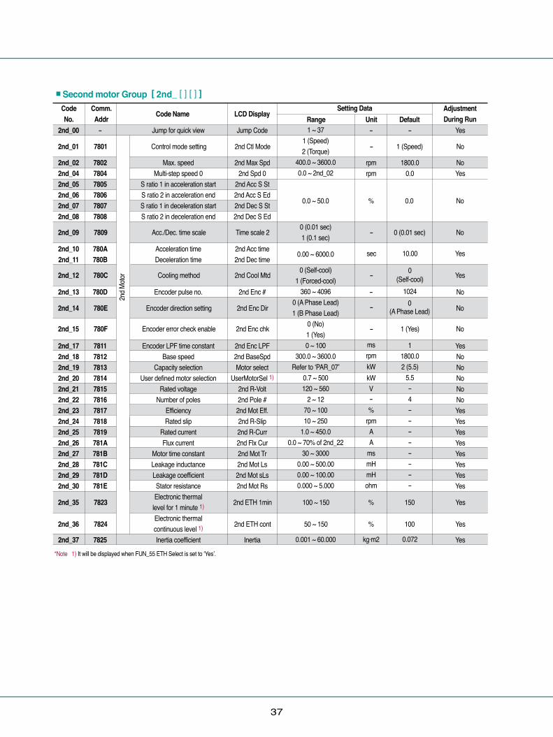
*Note 1) It will be displayed when FUN_55 ETH Select is set to ‘Yes’.
Comm.Addr
Code No. Code Name
1 ~ 371 (Speed)2 (Torque)
400.0 ~ 3600.00.0 ~ 2nd_02
0 (0.01 sec) 1 (0.1 sec)
0 (Self-cool)1 (Forced-cool)
360 ~ 40960 (A Phase Lead)1 (B Phase Lead)
0 (No)1 (Yes)0 ~ 100
300.0 ~ 3600.0Refer to ‘PAR_07’
0.7 ~ 500120 ~ 560
2 ~ 1270 ~ 10010 ~ 250
1.0 ~ 450.00.0 ~ 70% of 2nd_22
30 ~ 30000.00 ~ 500.000.00 ~ 100.000.000 ~ 5.000
0.001 ~ 60.000
Setting DataLCD Display
Range DefaultAdjustmentDuring Run Unit
Jump for quick view
Max. speed Multi-step speed 0
S ratio 1 in acceleration startS ratio 2 in acceleration endS ratio 1 in deceleration startS ratio 2 in deceleration end
Acceleration time Deceleration time
Encoder pulse no.
Encoder LPF time constant Base speed
Capacity selectionUser defined motor selection
Rated voltageNumber of poles
EfficiencyRated slip
Rated current Flux current
Motor time constant Leakage inductanceLeakage coefficient Stator resistance Electronic thermal
level for 1 minute 1)
Electronic thermal continuous level 1)
Inertia coefficient
Jump Code
2nd Max Spd2nd Spd 0
2nd Acc S St2nd Acc S Ed2nd Dec S St2nd Dec S Ed
2nd Acc time2nd Dec time
2nd Enc #
2nd Enc LPF2nd BaseSpdMotor select
UserMotorSel 1)
2nd R-Volt2nd Pole #2nd Mot Eff.2nd R-Slip2nd R-Curr2nd Flx Cur2nd Mot Tr2nd Mot Ls2nd Mot sLs2nd Mot Rs
Inertia
-
1800.00.0
0 (Self-cool)
1024
11800.02 (5.5)
5.5-4--------
0.072
-
rpmrpm
-
msrpmkWkWV-%
rpmAA
msmHmHohm
kg·m2
Yes
NoYes
No
YesNoNoNoNoNoYesYesYesYesYesYesYesYes
Yes
2nd_00
2nd_022nd_042nd_052nd_062nd_072nd_08
2nd_102nd_11
2nd_13
2nd_172nd_182nd_192nd_202nd_212nd_222nd_232nd_242nd_252nd_262nd_272nd_282nd_292nd_30
2nd_37
-
780278047805780678077808
780A780B
780D
781178127813781478157816781778187819781A781B781C781D781E
7825
■Second motor Group [ 2nd_ [ ] [ ] ]
2nd M
otor
Control mode setting
Acc./Dec. time scale
Encoder direction setting
Encoder error check enable
Cooling method
2nd Ctl Mode
Time scale 2
2nd Enc Dir
2nd Enc chk
2nd ETH 1min 100 ~ 150 % 150 Yes
% 100 Yes50 ~ 1502nd ETH cont
2nd Cool Mtd
0.0 ~ 50.0
0.00 ~ 6000.0
% 0.0 No
Yes
No
No
No
1 (Speed)
0 (0.01 sec)
0 (A Phase Lead)
-
-
-
-
-
sec 10.00
1 (Yes)
Yes
No7801
7809
780C
780E
780F
7823
7824
2nd_01
2nd_09
2nd_12
2nd_14
2nd_15
2nd_35
2nd_36
38
� � � � �� �
Function Codes Table
Comm.Addr
Code No. Code Name
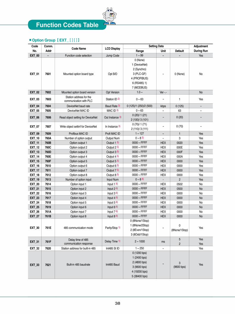
1 ~ 990 (None)
1 (DeviceNet)2 (Synchro)3 (PLC-GF)
4 (PROFIBUS)6 (RS485) 1)7 (MODBUS)
1.0 ~
0 (125)/1 (250)/2 (500)0 ~ 63
0 (20)/ 1 (21)2 (100)/ 3 (101)0 (70)/ 1 (71)
2 (110)/ 3 (111)1 ~ 1270 ~ 8 5)
0000 ~ FFFF0000 ~ FFFF0000 ~ FFFF0000 ~ FFFF0000 ~ FFFF0000 ~ FFFF0000 ~ FFFF0000 ~ FFFF
0 ~ 8 6)
0000 ~ FFFF0000 ~ FFFF0000 ~ FFFF0000 ~ FFFF0000 ~ FFFF0000 ~ FFFF0000 ~ FFFF0000 ~ FFFF
0 (8None/1Stop)1 (8None/2Stop)2 (8Even/1Stop)3 (8Odd/1Stop)
1 ~ 2500 (1200 bps)1 (2400 bps)2 (4800 bps)3 (9600 bps)4 (19200 bps)5 (38400 bps)
Setting DataLCD Display
Range DefaultAdjustmentDuring Run Unit
Function code selection
Mounted option board type
Mounted option board version
DeviceNet baud rateDeviceNet MAC ID
Profibus MAC ID
Number of option outputOption output 1Option output 2Option output 3Option output 4Option output 5Option output 6Option output 7Option output 8
Number of option inputOption input 1Option input 2Option input 3Option input 4Option input 5Option input 6Option input 7Option input 8
Station address for built-in 485
Built-in 485 baudrate
Jump Code
Opt B/D
Opt Version
Baud Rate 3)
MAC ID 3)
Profi MAC IDOutput NumOutput 1 5)
Output 2 5)
Output 3 5)
Output 4 5)
Output 5 5)
Output 6 5)
Output 7 5)
Output 8 5)
Input NumInput 1 6)
Input 2 6)
Input 3 6)
Input 4 6)
Input 5 6)
Input 6 6)
Input 7 6)
Input 8 6)
Int485 St ID
Int485 Baud
-
0 (None)
0 (125)63
13
0020000E000F000A0000000000000000
205020500000000000000000000000000
0 (8None/1Stop)
52
3 (9600 bps)
-
-
Ver -.-
kbps-
--
HEXHEXHEXHEXHEXHEXHEXHEX
-HEXHEXHEXHEXHEXHEXHEXHEX
-
ms
-
-
Yes
No
No
--
YesYesYesYesYesYesYesYesYesYesYesNoNoNoNoNoNoNoNo
YesYesYes
Yes
EXT_00
EXT_01
EXT_02
EXT_04EXT_05
EXT_09EXT_10EXT_11EXT_12EXT_13EXT_14EXT_15EXT_16EXT_17EXT_18EXT_19EXT_20EXT_21EXT_22EXT_23EXT_24EXT_25EXT_26EXT_27
EXT_32
EXT_33
-
7601
7602
76047605
7609760A760B760C760D760E760F7610761176127613761476157616761776187619761A761B
7620
7621
■Option Group [ EXT_ [ ] [ ] ]
Station ID 2)
Out Instance 3)
In Instance 3)
0 ~ 63 1 Yes-
-
-
-
-
0 (20)
0 (70)
7603EXT_03
7606EXT_06
7607EXT_07
761EEXT_30
761FEXT_31
Parity/Stop 1) Yes485 communication mode
Delay time of 485 communication response 2 ~ 1000Delay Time 1)
Station address for the communication with PLC
Read object setting for DeviceNet
Write object settinf for DeviceNet

39
*Note 1) It will be displayed when RS-485 communication option board is installed. 2) It will be displayed when PLC-GF communication option board is installed. 3) It will be displayed when DeviceNet communication option board is installed. 4) It will be displayed when Profibus communication option b oard is installed. 5) From EXT_11 to EXT_18 (Option ouput) are displayed according to the number from EXT_11. 6) From EXT_20 to EXT_27 (Option input) are displayed according to the number from EXT_19. 7) Refer to the appropriate option manual.
Comm.Addr
Code No. Code Name
0 (8None/1Stop)1 (8None/2Stop)2 (8Even/1Stop)3 (8Odd/1Stop)
0 (None) 1 (FreeRun)
2 (Stop)
Setting DataLCD Display
Range DefaultAdjustmentDuring Run Unit
-
-
Yes
- Yes
0 (No) No
0 (None) Yes
Yes
7623EXT_35
7622EXT_34
7624EXT_36
7625EXT_37
7663EXT_99
Delay time for built-in 485 communication response
Built-in 485 communication mode
Run method when the command of built-in 485 is lost.
Decision time for losing the command of built-in 485
Decision time for losing the command of built-in 485
Int485 Delay
Int485 Mode
-
-
-
-
-
2 ~ 1000
Int485 LostC
Int485 LostT 1.0 ~ 30.0
Comm UpDate 4) 0 (No) / 1 (Yes)

40
� � � � �� �
Function Codes Table
Comm.Addr
Code No. Code Name
1 ~ 8300 (Not Used)01 (Speed Ref)
02 (Proc PID Ref)03 (Proc PID F/B)
04 (Draw Ref)05 (Torque Ref)
06 (Flux Ref)07 (Torque Bias)08 (Torque Limit)
09 (Line SPD Ref) 1)
10 (Tension Ref) 1)
11 (Dancer Ref) 1)
12 (Taper Ref) 1)
13 (Tension F/B) 1)
14 (Diameter) 1)
15 (Diam Preset) 1)
0 (-10 ⇒ 10V)1 (10 ⇒ -10V)2 (0 ⇒ 10V)3 (10 ⇒ 0V)
4 (0 ⇒ 20mA)5 (20 ⇒ 0mA)
0.00 ~ Ai1 In X2-10.00 ~ Ai1 Out Y2
0.00 ~ 100.000.00 ~ 250.00
Ai1 -In X2 ~ 0.00Ai1 -Out Y2 ~ 10.00
-100.00 ~ 0.00-250.00 ~ 0.00
0 ~ 20000 (None)
1 (Half of x1)2 (Below x1)
Setting DataLCD Display
Range DefaultAdjustmentDuring Run Unit
Select code number
Source definition
Minimum VoltageMinimum Voltage Bias
Maximum VoltageMaximum Voltage Gain
Minimum VoltageMinimum Voltage Bias
Maximum VoltageMaximum Voltage Gain
LPF time constant
Multi-function Analog input Ai2 Definition
Source definitionMinimum Voltage
Minimum Voltage BiasMaximum Voltage
Maximum Voltage GainMinimum Voltage
Minimum Voltage BiasMaximum Voltage
Maximum Voltage GainLPF time constant
Loss commandCriterion select
Jump Code
Ai1 Define
Ai1 Source
Ai1 In X1Ai1 Out Y1Ai1 In X2
Ai1 Out Y2Ai1 -In X1
Ai1 -Out Y1Ai1 -In X2
Ai1 -Out Y2Ai1 LPF
Ai2 SourceAi2 In X1
Ai2 Out Y1Ai2 In X2
Ai2 Out Y2Ai2 -In X1
Ai2 -Out Y1Ai2 -In X2
Ai2 -Out Y2Ai2 LPF
-
0 (Not Used)
0 (Not Used)
0.000.00
100.00100.000.0010.00
-100.00-100.00
-
0 (None)
-
-
%%%%%%%%ms
-
Yes
No
No
YesYesYesYesYesYesYesYes
No
AIO_00
AIO_01
AIO_02
AIO_03AIO_04AIO_05AIO_06AIO_07AIO_08AIO_09AIO_10AIO_11
AIO_14AIO_15AIO_16AIO_17AIO_18AIO_19AIO_20AIO_21AIO_22AIO_23
-
7701
7702
7703770477057706770777087709770A770B
770E770F77107711771277137714771577167717
■Analog AIO Group [ AIO_ [ ] [ ] ]
-
770CAIO_12
770DAIO_13 Ai2 Define
Refer to AIO_01~12
Ai2 Wbroken7718AIO_24
Multi-function Analog input Ai1 definition
Torq
ueM
ulti-
func
tion
Ana
log
Inpu
t Ai2
Ai1 WbrokenCommand lossCriterion select
*Note 1) Displayed only when WEB mode setting

41
Comm.Addr
Code No. Code Name
Refer to AIO_01∫
Possible to select NTC motor17 (Use Mot NTC)
Refer to AIO_01 ∫
When using EXTN_I/O motor NTC/PTC function is available at Ai5
17(Use Mot NTC)
0 (-10 ⇒ 10V)1 (10 ⇒ -10V)2 (0 ⇒ 10V)3 (10 ⇒ 0V)
0 (-10 ⇒ 10V)1 (10 ⇒ -10V)2 (0 ⇒ 10V)3 (10 ⇒ 0V)
Setting DataLCD Display
Range DefaultAdjustmentDuring Run Unit
Minimum VoltageMinimum Voltage Bias
Maximum VoltageMaximum Voltage Gain
Minimum VoltageMinimum Voltage Bias
Maximum VoltageMaximum Voltage GainInput LPF time constant
Multi-function Analog input Ai4 Definition 1)
Source Definition 1)
Minimum Voltage 1)
Minimum Voltage Bias 1)
Maximum Voltage 1)
Maximum Voltage Gain 1)
Minimum Voltage 1)
Minimum Voltage Bias 1)
Maximum Voltage 1)
Maximum Voltage Gain 1)
Output LPF time constant 1)
Command loss criterion select 1)
Minimum Voltage 1)
Minimum Voltage Bias 1)
Maximum Voltage 1)
Maximum Voltage Gain 1)
Minimum Voltage 1)
Minimum Voltage Bias 1)
Maximum Voltage 1)
Maximum Voltage Gain 1)
Input LPF time constant 1)
Command loss criterion select 1)
Ai3 In X1Ai3 Out Y1Ai3 In X2
Ai3 Out Y2Ai3 -In X1
Ai3 -Out Y1Ai3 -In X2Ai3-Out Y2
Ai3 LPF
Ai4 SourceAi4 In X1
Ai4 Out Y1Ai4 In X2
Ai4 Out Y2Ai4 -In X1
Ai4 -Out Y1Ai4 -In X2
Ai4 -Out Y2Ai4 LPF
Ai4 Wbroken
Ai5 In X1Ai5 Out Y1Ai5 In X2
Ai5 Out Y2Ai5 -In X1
Ai5 -Out Y1Ai5 -In X2
Ai5 -Out Y2Ai5 LPF
Ai5 Wbroken
AIO_27AIO_28AIO_29AIO_30AIO_31AIO_32AIO_33AIO 34AIO 34
AIO_38AIO_39AIO_40AIO_41AIO_42AIO_43AIO_44AIO_45AIO_46AIO_47AIO_48
AIO_51AIO_52AIO_53AIO_54AIO_55AIO_56AIO_57AIO_58AIO_59AIO_60
771B771C771D771E771F7720772177227723
7726772777287729772A772B772C772D772E772F7730
7733773477357736773777387739773A773B773C
7719AIO_25
Refer to AIO_03~12
Refer to AIO_03~12
7731AIO_49
7732AIO_50
7724AIO_36
AIO_37
Multi-function Analog input Command loss criterion select
Multi-function Analog input Ai3 Definition
Source Definition
0 (Not Used)
0 (Not Used)
0 (-10 ⇒ 10V)
0 (-10 ⇒ 10V)
Ai3 Define
Ai3 Source
Ai3 Wbroken
Ai4 Define
No
No
No
No
-
-
Mul
ti-fu
nctio
n A
nalo
g In
put A
i3M
ulti-
func
tion
Ana
log
Inpu
t Ai2
Multi-function Analog input Ai5 Definition 1) Ai5 Define
Ai5 SourceSource Definition 1)
771AAIO_26
42
� � � � �� �
Function Codes Table
Comm.Addr
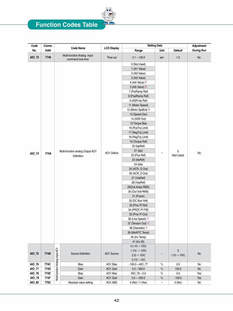
7749
774A
Code No.
AIO_73
AIO_74
Code Name
Multi-function analog Output AO1 Definition
0 (Not Used)1 (Ai1 Value)2 (Ai2 Value)3 (Ai3 Value)
4 (Ai4 Value) 2)
5 (Ai5 Value) 2)
7 (PreRamp Ref)8 (PostRamp Ref)9 (ASR Inp Ref)
11 (Motor Speed)12 (Motor SpdEst) 3)
13 (Speed Dev)14 (ASR Out)
15 Torque Bias16 (PosTrq Limit)17 (NegTrq Limit)18 (RegTrq Limit)19 (Torque Ref)
20 (IqeRef)21 (Iqe)
22 (Flux Ref)23 (IdeRef)
24 (Ide)25 (ACR_Q Out)26 (ACR_D Out)
27 (VdeRef)28 (VqeRef)
29(Out Amps RMS)30 (Out Volt RMS)
31 (Power)32 (DC Bus Volt)33 (Proc PI Ref)
34 (PROC PI F/B)35 (Proc PI Out)
36 (Line Speed) 1)
37 (Tension Out) 1)
38 (Diameter) 1)
39 (MotNTC Temp)40 (Inv Temp)
41 (Inv i2t)
Setting DataLCD Display
Range Default
0(Not Used)
AdjustmentDuring Run
No
Unit
Time out sec 1.0
AO1 Define
0.1 ~ 120.0
-
NoMulti-function Analog input command loss time
0 (-10 ⇒ 10V)1 (10 ⇒ -10V)2 (0 ⇒ 10V)3 (10 ⇒ 0V)
-100.0 ~ AIO_770.0 ~ 500.0
AIO_79 ~ 0.00.0 ~ -500.0
0 (No) / 1 (Yes)
Source Definition
BiasGainBiasGain
Absolute value setting
AO1 Source
AO1 BiasAO1 GainAO1 BiasAO1 GainAO1 ABS
0 (-10 ⇒ 10V)
0.0100.00.0
-100.00 (No)
-
%%%%-
No
NoNoYesYesNo
AIO_75
AIO_76AIO_77AIO_78 AIO_79AIO_80
774B
774C774D774E774F7750
Multi-
functi
on An
alog I
nput
AO1
43
*Note 1) Displayed only when WEB mode setting. 2) It is available when Extension I/O (EXTN_I/O) is applied. 3) It will be displayed when CON_01 is set to ‘Sensorless’.
Comm.Addr
Code No. Code Name
Setting DataLCD Display
Range DefaultAdjustmentDuring Run Unit
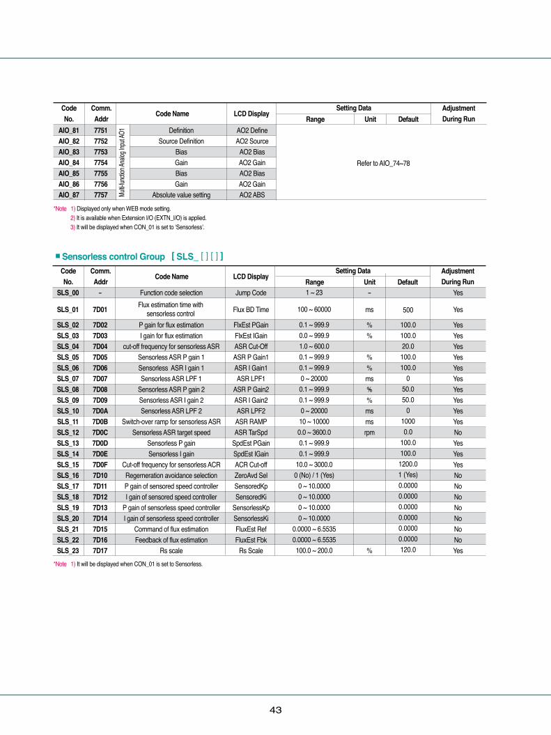
7751775277537754775577567757
AIO_81AIO_82AIO_83AIO_84AIO_85AIO_86AIO_87
DefinitionSource Definition
BiasGainBiasGain
Absolute value setting
Refer to AIO_74~78
AO2 DefineAO2 Source
AO2 BiasAO2 GainAO2 BiasAO2 GainAO2 ABSMu
lti-fun
ction A
nalog
Inpu
t AO1
Comm.Addr
Code No. Code Name
1 ~ 23
100 ~ 60000
0.1 ~ 999.90.0 ~ 999.91.0 ~ 600.00.1 ~ 999.90.1 ~ 999.90 ~ 200000.1 ~ 999.90.1 ~ 999.90 ~ 2000010 ~ 100000.0 ~ 3600.00.1 ~ 999.90.1 ~ 999.9
10.0 ~ 3000.00 (No) / 1 (Yes)
0 ~ 10.00000 ~ 10.00000 ~ 10.00000 ~ 10.0000
0.0000 ~ 6.55350.0000 ~ 6.5535100.0 ~ 200.0
Setting DataLCD Display
Range DefaultAdjustmentDuring Run Unit
Function code selection
P gain for flux estimationI gain for flux estimation
cut-off frequency for sensorless ASR Sensorless ASR P gain 1Sensorless ASR I gain 1Sensorless ASR LPF 1
Sensorless ASR P gain 2Sensorless ASR I gain 2Sensorless ASR LPF 2
Switch-over ramp for sensorless ASR Sensorless ASR target speed
Sensorless P gainSensorless I gain
Cut-off frequency for sensorless ACR Regerneration avoidance selectionP gain of sensored speed controller I gain of sensored speed controller
P gain of sensorless speed controllerI gain of sensorless speed controller
Command of flux estimationFeedback of flux estimation
Rs scale
Jump Code
Flux BD Time
FlxEst PGainFlxEst IGainASR Cut-OffASR P Gain1ASR I Gain1ASR LPF1
ASR P Gain2ASR I Gain2ASR LPF2ASR RAMPASR TarSpd
SpdEst PGainSpdEst IGainACR Cut-offZeroAvd SelSensoredKpSensoredKi
SensorlessKpSensorlessKiFluxEst RefFluxEst Fbk
Rs Scale
500
100.0100.020.0100.0100.0
050.050.0
010000.0
100.0100.01200.01 (Yes)0.00000.00000.00000.00000.00000.0000120.0
-
ms
%%
%%ms%%msmsrpm
%
Yes
Yes
YesYesYesYesYesYesYesYesYesYesNoYesYesYesNoNoNoNoNoNoNoYes
SLS_00
SLS_01
SLS_02SLS_03SLS_04SLS_05SLS_06SLS_07SLS_08SLS_09SLS_10SLS_11SLS_12SLS_13SLS_14SLS_15SLS_16SLS_17SLS_18SLS_19SLS_20SLS_21SLS_22SLS_23
-
7D01
7D027D037D047D057D067D077D087D097D0A7D0B7D0C7D0D7D0E7D0F7D107D117D127D137D147D157D167D17
■Sensorless control Group [ SLS_ [ ] [ ] ]
-
Flux estimation time with sensorless control
*Note 1) It will be displayed when CON_01 is set to Sensorless.
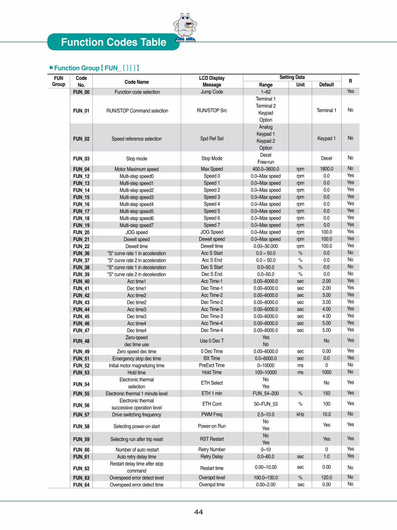
44
FUNGroup
Code No.
FUN_00
FUN_01
FUN_02
FUN_03
FUN_04FUN_12FUN_13FUN_14FUN_15FUN_16FUN_17FUN_18FUN_19FUN_20FUN_21FUN_22FUN_36FUN_37FUN_38FUN_39FUN_40FUN_41FUN_42FUN_43FUN_44FUN_45FUN_46FUN_47
FUN_48
FUN_49FUN_51FUN_52FUN_53
FUN_54FUN_55
FUN_56FUN_57
FUN_58
FUN_59
FUN_60FUN_61
FUN_62FUN_63FUN_64
Code Name
Function code selection
RUN/STOP Command selection
Speed reference selection
Stop mode
Motor Maximum speedMulti-step speed0Multi-step speed1Multi-step speed2Multi-step speed3Multi-step speed4Multi-step speed5Multi-step speed6Multi-step speed7
JOG speedDewell speedDewell time
"S" curve rate 1 in acceleration"S" curve rate 2 in acceleration "S" curve rate 1 in deceleration "S" curve rate 2 in deceleration
Acc time1Dec time1Acc time2Dec time2Acc time3Dec time3Acc time4Dec time4
Zero-speed dec time use
Zero speed dec timeEmergency stop dec time
Initial motor magnetizing timeHold time
Electronic thermal selection
Electronic thermal 1 minute level Electronic thermal
successive operation levelDrive switching frequency
Selecting power-on start
Selecting run after trip reset
Number of auto restartAuto retry delay time
Restart delay time after stop command
Overspeed error detect levelOverspeed error detect time
Setting DataRange1~62
Terminal 1Terminal 2
KeypadOptionAnalog
Keypad 1Keypad 2
OptionDecel
Free-run400.0~3600.0
0.0~Max speed0.0~Max speed0.0~Max speed0.0~Max speed0.0~Max speed0.0~Max speed0.0~Max speed0.0~Max speed0.0~Max speed0.0~Max speed
0.00~30.0000.0 ~ 50.00.0 ~ 50.00.0~50.00.0~50.0
0.00~6000.00.00~6000.00.00~6000.00.00~6000.00.00~6000.00.00~6000.00.00~6000.00.00~6000.0
YesNo
0.00~6000.00.0~6000.00~10000
100~10000NoYes
FUN_54~200
50~FUN_53
2.5~10.0NoYesNoYes
0~100.0~60.0
0.00~10.00
100.0~130.00.00~2.00
Unit
rpmrpmrpmrpmrpmrpmrpmrpmrpmrpmrpmrpm%%%%
secsecsecsecsecsecsecsec
secsecmsms
%
%
kHz
sec
sec
% sec
Default
Terminal 1
Keypad 1
Decel
1800.00.00.00.00.00.00.00.00.0
100.0100.0100.00.00.00.00.02.002.003.003.004.004.005.005.00
No
0.000.00
1000
No
150
100
10.0
Yes
Yes
01.0
0.00
120.00.00
R
Yes
No
No
No
NoYesYesYesYesYesYesYesYesYesYesYesNoNoNoNoYesYesYesYesYesYesYesYes
Yes
YesYesNoNo
Yes
Yes
Yes
No
Yes
Yes
YesYes
NoNoNo
■Function Group [ FUN_ [ ] [ ] ]LCD Display
MessageJump Code
RUN/STOP Src
Spd Ref Sel
Stop Mode
Max SpeedSpeed 0Speed 1Speed 2Speed 3Speed 4Speed 5Speed 6Speed 7
JOG SpeedDewell speedDewell timeAcc S StartAcc S EndDec S StartDec S EndAcc Time-1Dec Time-1Acc Time-2Dec Time-2Acc Time-3Dec Time-3Acc Time-4Dec Time-4
Use 0 Dec T
0 Dec TimeBX Time
PreExct TimeHold Time
ETH Select
ETH 1 min
ETH Cont
PWM Freq
Power-on Run
RST Restart
Retry NumberRetry Delay
Restart timeOverspd levelOverspd time
� � � � �� �
Function Codes Table

45
Code No.
CON_00
CON_01
CON_02
CON_03CON_04CON_05CON_06CON_07CON_08CON_09CON_10CON_11CON_12CON_13CON_14CON_15CON_16CON_17CON_18CON_19
CON_20
CON_21CON_22CON_23CON_24CON_25
CON_26
CON_27
CON_28
CON_29CON_30CON_31
CON_32
CON_33
CON_34
CON_35
CON_49
Code Name
Function code selection
Control mode selection
Drive application mode selection
ASR P Gain1ASR I Gain1
ASR input LPF time constant1ASR P Gain2ASR I Gain2
ASR input LPF time constant 2Ramp time in gain switching
Gain switching speedProcess PID command( Loader)Process PID position standard
Process PID P gainProcess PID I gainProcess PID D gain
Process PID positive limitProcess PID negative limit
Process PID output LPF time constantProcess PID output gain
Process PID output enable
Process PID Hold timeDraw set up percentage
Droop control percentageDroop control minimum speed Droop control minimum torque
Torque reference value selection
Torque reference (Loader)
Torque limit definition
Forward torque limitReverse torque limit
Regenerative torque limit
Torque bias selection
Torque bias volumeTorque bias compensation volume of friction
factor Torque balance percentage
Speed search selection
Range1 ~ 47SpeedTorque
General Vect/Elevator
0.0 ~ 200.00 ~ 500000 ~ 200000.0 ~ 200.00 ~ 500000 ~ 2000010 ~ 100000.0 ~ 3600.0
-100.0 ~ 100.00 ~ 655350.0 ~ 999.90.0 ~ 100.00.0 ~ 100.0
-100.0 ~100.0-100.0 ~100.0
0 ~ 500-250.0 ~ 250.0
DisableEnable
Terminal0~10000
-100.0 ~ 100.00.0 ~ 100.00.0 ~ 3600.00.0 ~ 100.0
NoneAnalogOption
-180.0~180.0Kpd Kpd KpdKpd Kpd AxKpd Ax KpdKpd Ax Ax
Ax Kpd KpdAx Kpd AxAx Ax KpdAx Ax Ax
Opt Opt Opt0.0 ~ 250.00.0 ~ 250.00.0 ~ 250.0
NoneAnalogKeypadOption
-150.0 ~ 150.0
-150.0 ~ 150.0
0.0 ~ 100.00000~1111(Bit set up)
Unit
%msms%msmsmsrpm%%%%%%%ms%
ms%%
rpm%
%
%%%
%
%
%
R
Yes
No
No
YesYesYesYesYesYesYesNoYesNoYesYesYesYesYesYesYes
No
NoYesYesYesYes
No
Yes
No
YesYesYes
No
Yes
Yes
Yes
No
LCD DisplayMessage
Jump Code
Control Mode
Application
ASR P Gain1ASR I Gain1ASR LPF1
ASR P Gain2ASR I Gain2ASR LPF2ASR RampASR TarSpdProc PID RefProc Posi RefProc PID KpProc PID Kt
PROC PID KdProc PID LmtProc Neg LmtProc Out LPFProc OutGain
Proc PID Enb
PID Hold timeDraw %Droop %
Droop MinSPdDroop MinTrd
Trq Ref Src
Trq Ref
Trq Lmt Src
Pos Trq LmtNeg Trq LmtReg Trq Lmt
Trq Bias Src
Trq Bias
Trq Bias FF
Trq Bias F
Speed search
CONGroup
Setting Data
■Control Group [CON_ [ ] [ ] ]
Default
Speed
General Vect5.0
30000
50.03000
10000.00.00
0.00.00.01001000
0.0
Disable
00.00.00.00.0
None
0.0
Kpd KpdKpd
150.0150.0150.0
None
0.0
0.0
50.0
0100
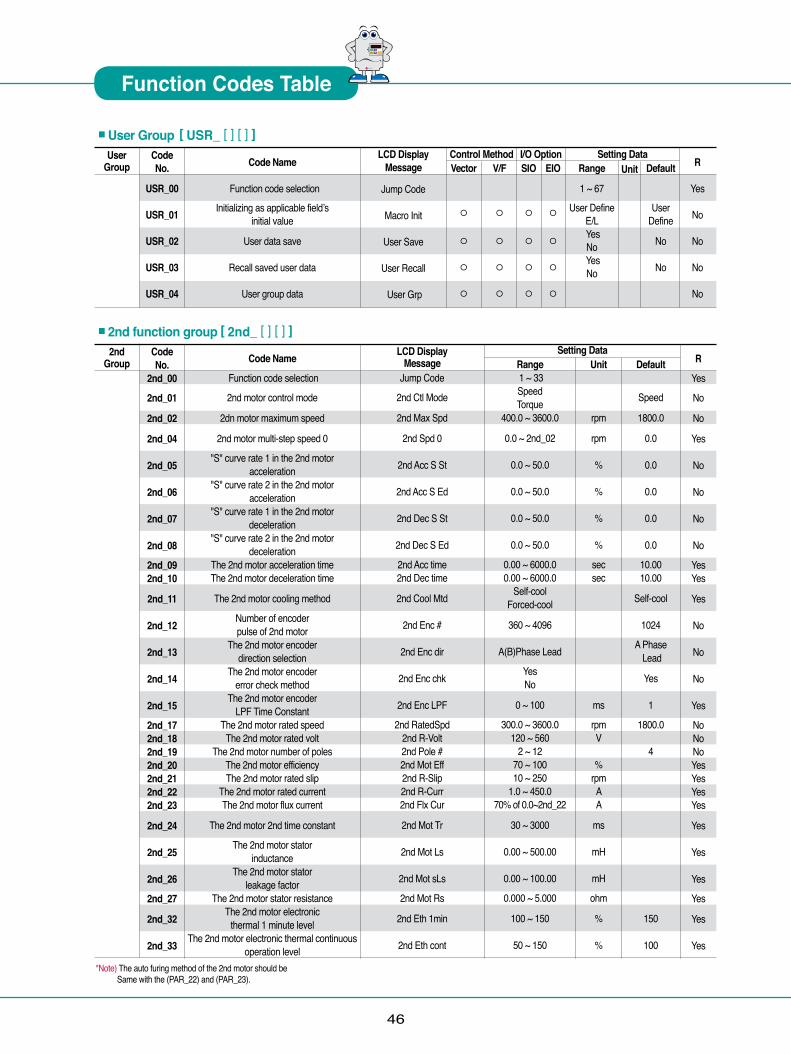
46
UserGroup
Code No.
USR_00
USR_01
USR_02
USR_03
USR_04
Code Name
Function code selection
Initializing as applicable fieldʼsinitial value
User data save
Recall saved user data
User group data
Control Method I/O Option Setting DataVector
◦
◦
◦
◦
V/F
◦
◦
◦
◦
SIO
◦
◦
◦
◦
EIO
◦
◦
◦
◦
Range
1 ~ 67
User DefineE/L YesNo
YesNo
Unit Default
User Define
No
No
R
Yes
No
No
No
No
■User Group [ USR_ [ ] [ ] ]LCD Display
Message
Jump Code
Macro Init
User Save
User Recall
User Grp
2ndGroup
Code No.
2nd_00
2nd_01
2nd_02
2nd_04
2nd_05
2nd_06
2nd_07
2nd_08
2nd_092nd_10
2nd_11
2nd_12
2nd_13
2nd_14
2nd_15
2nd_172nd_182nd_192nd_202nd_212nd_222nd_23
2nd_24
2nd_25
2nd_26
2nd_27
2nd_32
2nd_33
Code Name
Function code selection
2nd motor control mode
2dn motor maximum speed
2nd motor multi-step speed 0
"S" curve rate 1 in the 2nd motor acceleration
"S" curve rate 2 in the 2nd motor acceleration
"S" curve rate 1 in the 2nd motor deceleration
"S" curve rate 2 in the 2nd motor deceleration
The 2nd motor acceleration time The 2nd motor deceleration time
The 2nd motor cooling method
Number of encoder pulse of 2nd motor
The 2nd motor encoder direction selection
The 2nd motor encoder error check method
The 2nd motor encoder LPF Time Constant
The 2nd motor rated speedThe 2nd motor rated volt
The 2nd motor number of polesThe 2nd motor efficiencyThe 2nd motor rated slip
The 2nd motor rated currentThe 2nd motor flux current
The 2nd motor 2nd time constant
The 2nd motor stator inductance
The 2nd motor stator leakage factor
The 2nd motor stator resistanceThe 2nd motor electronic
thermal 1 minute levelThe 2nd motor electronic thermal continuous
operation level
Setting DataRange 1 ~ 33SpeedTorque
400.0 ~ 3600.0
0.0 ~ 2nd_02
0.0 ~ 50.0
0.0 ~ 50.0
0.0 ~ 50.0
0.0 ~ 50.0
0.00 ~ 6000.00.00 ~ 6000.0
Self-coolForced-cool
360 ~ 4096
A(B)Phase Lead
YesNo
0 ~ 100
300.0 ~ 3600.0120 ~ 560
2 ~ 1270 ~ 10010 ~ 250
1.0 ~ 450.070% of 0.0~2nd_22
30 ~ 3000
0.00 ~ 500.00
0.00 ~ 100.00
0.000 ~ 5.000
100 ~ 150
50 ~ 150
Unit
rpm
rpm
%
%
%
%
secsec
ms
rpmV
%rpmAA
ms
mH
mH
ohm
%
%
Default
Speed
1800.0
0.0
0.0
0.0
0.0
0.0
10.0010.00
Self-cool
1024
A Phase Lead
Yes
1
1800.0
4
150
100
R
Yes
No
No
Yes
No
No
No
No
YesYes
Yes
No
No
No
Yes
NoNoNoYesYesYesYes
Yes
Yes
Yes
Yes
Yes
Yes
■2nd function group [ 2nd_ [ ] [ ] ]LCD Display
MessageJump Code
2nd Ctl Mode
2nd Max Spd
2nd Spd 0
2nd Acc S St
2nd Acc S Ed
2nd Dec S St
2nd Dec S Ed
2nd Acc time2nd Dec time
2nd Cool Mtd
2nd Enc #
2nd Enc dir
2nd Enc chk
2nd Enc LPF
2nd RatedSpd2nd R-Volt2nd Pole #2nd Mot Eff2nd R-Slip2nd R-Curr2nd Flx Cur
2nd Mot Tr
2nd Mot Ls
2nd Mot sLs
2nd Mot Rs
2nd Eth 1min
2nd Eth cont
*Note) The auto furing method of the 2nd motor should be Same with the (PAR_22) and (PAR_23).
� � � � �� �
Function Codes Table

2. SV0300iV5-2/4 ~ SV0370iV5-2/4, SV0450iV5-4 ~ SV3750iV5-4① SV037DBH-2: 37kW/200V Class Braking Unit (10% ED) ② SV037DBH-4: 37kW/400V Class Braking Unit (10% ED)③ SV075DBH-4: 75kW/400V Class Braking Unit (10% ED) ④ SV075DB-4 : 75kW/400V Class Braking Unit (100% ED)⑤ SV220DB-4 : 220kW/400V Class Braking Unit (100% ED)- The Combination of two braking unit for 400V class is possible for more than SV900iV5-4 capacity.- When ED is more than 10%, Use the braking unit for 100% ED (Ex: vertical load such as carne, hoist)- When the drive capacity is more than 220kW, use the braking unit for SV2200DB-4 (100% ED).- Refer to description manual included in braking unit product for the use of 100% ED braking unit.
47
1) Braking resistor specifications in capacityResistance values in the table shown below are calculated based on the 150%, 5%ED standard. In case of 10%ED use, resistor with double rated value should be used. resistors ̓rated watt.
1) Combination of braking unit 2) Braking resistor for braking unit
2) Brake resistor wiringBrake resistor has attached a temperature detectable sensor for fire protection.See below when in use.
1. SV0055iV5-2/4 ~ SV0220iV5-2/4 : Built-in Brake Unit
▶ ED 100sec standard. ▶ Resistance value is based on the self-cooling standard.
Type
BR0800W020JBR01200W015JBR2400W010JBR2400W008JBR3600W005JBR3600W005JBR1000W085JBR1200W060JBR2400W040JBR2400W030JBR3600W020JBR3600W020J
Applicable Drives
SV 0055iV5-2 DBSV 0075iV5-2 DBSV 0110iV5-2 DBSV 0150iV5-2 DBSV 0185iV5-2 DBSV 0220iV5-2 DBSV 0055iV5-4 DBSV 0075iV5-4 DBSV 0110iV5-4 DBSV 0150iV5-4 DBSV 0185iV5-4 DBSV 0220iV5-4 DB
[ ㏀ ] 201510855856040302020
Capacity(5%ED)[W]8001200240024003600360080012002400240036003600
Brake resistor terminal blocks
B1, B2
P7, CM
Drive terminals
P,BROne of the multi function input terminals, out of P1~P7, of control terminals board is used as defining "External trip signal contact B"
Operation
The contact is ON in normal temperature and opens in overheat.
● Terminal functions
Terminal name Description P/B1 Connection to drive terminal P2 or P and B2 of braking resistor. N Connection to drive terminal N B2 Connection to brake resistor B2 G Ground terminal IN+ Control connection lint(used when SLAVE MODE) IN- Control connection lint(used when SLAVE MODE) OUT+ Control connection lint(used when MASTER MODE) OUT- Control connection lint(used when MASTER MODE) Fault signal output terminal, when the protection function of 30A/30B/30C braking unit operates. 30A : Contact A, 30B : Contact B, 30C COMMON
� � � � �� �
Braking Unit and Resistor
DriveBraking unit 200V 37kW 37kW 400V 75kW 220kW
SV[ ] [ ] [ ] [ ] iV5-2 SV [ ] [ ] [ ] [ ] iV5-4 0300 / 0370 0300 / 0370 0450 / 0550 / 0750 0900 / 1100 / 1320 / 1600 2200 2800 / 3150 / 3750 1 1 1 2 1 2
Braking Unit 100% of Braking Torque, 10% ED Resistance [Ω] Rated Power [kW] 37kW ~ 200kW 3 5 37kW ~ 400kW 12 5 75kW ~ 400kW 6 10 75kW ~ 400kW 6 200kw ~ 400kW 2Note) 1. Example) Combine two braking units of 75kW ~ 400V Class for SV-900iV5-4(90kW) Class.
2.Refer to the Braking Unit user manual that came with the braking unit.
Refer th extra manual inthe case of 100% ED
braking unit.
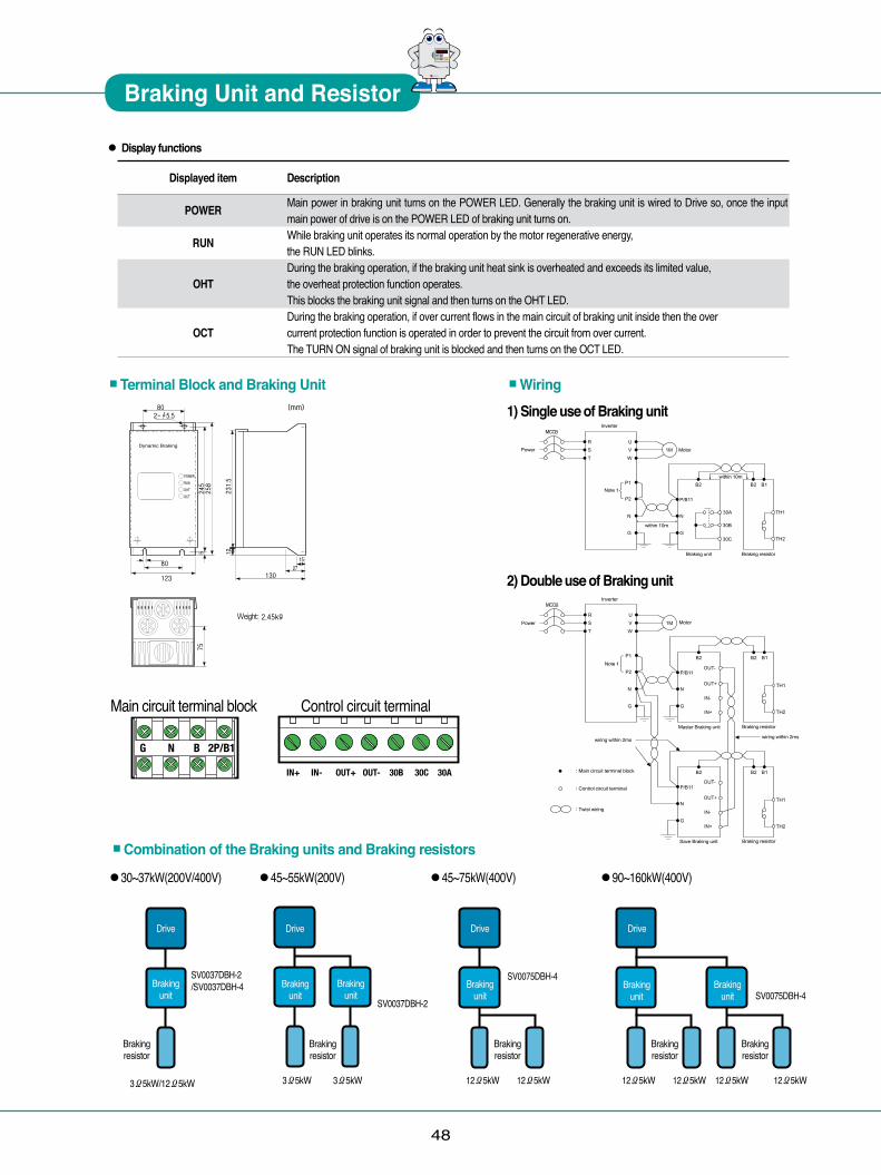
48
● Display functions
Displayed item Description POWER Main power in braking unit turns on the POWER LED. Generally the braking unit is wired to Drive so, once the input
main power of drive is on the POWER LED of braking unit turns on. RUN While braking unit operates its normal operation by the motor regenerative energy, the RUN LED blinks. During the braking operation, if the braking unit heat sink is overheated and exceeds its limited value, OHT the overheat protection function operates. This blocks the braking unit signal and then turns on the OHT LED. During the braking operation, if over current flows in the main circuit of braking unit inside then the over OCT current protection function is operated in order to prevent the circuit from over current. The TURN ON signal of braking unit is blocked and then turns on the OCT LED.
■Terminal Block and Braking Unit ■Wiring
Power
Inverter
Power
Inverter
Note 1
Note 1
Motor
Motor
within 10m
within 10m
Braking unit
Master Braking unit
Braking resistor
Braking resistor
Save Braking unit Braking resistor
wiring within 2mswiring within 2ms
Main circuit terminal block
Control circuit terminal
Twist wiring
Power
Inverter
Power
Inverter
Note 1
Note 1
Motor
Motor
within 10m
within 10m
Braking unit
Master Braking unit
Braking resistor
Braking resistor
Save Braking unit Braking resistor
wiring within 2mswiring within 2ms
Main circuit terminal block
Control circuit terminal
Twist wiring
Power
Inverter
Power
Inverter
Note 1
Note 1
Motor
Motor
within 10m
within 10m
Braking unit
Master Braking unit
Braking resistor
Braking resistor
Save Braking unit Braking resistor
wiring within 2mswiring within 2ms
Main circuit terminal block
Control circuit terminal
Twist wiring
1) Single use of Braking unit
2) Double use of Braking unit
Main circuit terminal block Control circuit terminal
■Combination of the Braking units and Braking resistors
●30~37kW(200V/400V) ●45~55kW(200V) ●45~75kW(400V) ●90~160kW(400V)
Drive
Braking unit
Braking resistor
SV0037DBH-2/SV0037DBH-4
3Ω5kW/12Ω5kW
Drive
Braking unit
Braking unit
Braking resistor
SV0037DBH-2
Drive
Braking unit 제동유닛
Braking resistor
SV0075DBH-4
Drive
Braking unit
Braking unit
Braking resistor
Braking resistor
SV0075DBH-4
12Ω5kW12Ω5kW12Ω5kW12Ω5kW12Ω5kW12Ω5kW3Ω5kW3Ω5kW
Power
Inverter
Power
Inverter
Note 1
Note 1
Motor
Motor
within 10m
within 10m
Braking unit
Master Braking unit
Braking resistor
Braking resistor
Save Braking unit Braking resistor
wiring within 2mswiring within 2ms
Main circuit terminal block
Control circuit terminal
Twist wiring
� � � � �� �
Braking Unit and Resistor

● MCCB (Molded Case Circuit Breaker) and MC (Magnetic Contactor)
49
� � � � �� �
Peripheral Device
Voltage
200VClass
400VClass
Motor [kW]2.23.75.57.51115
18.52230372.23.75.57.51115
18.522303745557590110132160220280315375
Drive ModelSV022iV5-2DBSV037iV5-2DBSV055iV5-2DBSV075iV5-2DBSV110iV5-2DBSV150iV5-2DBSV185iV5-2DBSV220iV5-2DB
SV300iV5-2SV370iV5-2
SV022iV5-4DBSV037iV5-4DBSV055iV5-4DBSV075iV5-4DBSV110iV5-4DBSV150iV5-4DBSV185iV5-4DBSV220iV5-4DB
SV300iV5-4(380V)SV370iV5-4(380V)SV450iV5-4(380V)SV550iV5-4(380V)SV750iV5-4(380V)SV900iV5-4(380V)SV1100iV5-4(380V)SV1320iV5-4(380V)SV1600iV5-4(380V)SV2200iV5-4(380V)
SV2800iV5-4SV3150iV5-4SV3750iV5-4
UTS100NUTS100NUTS150LUTS150LUTS150LUTS150LUTS150LUTS150LUTS150LUTS400LUTS100NUTS100NUTS100NUTS150LUTS150LUTS150LUTS150LUTS150LUTS150LUTS150LUTS150LUTS400LUTS400LUTS400LUTS400LUTS400LUTS400LUTS600LUTS800LUTS800LUTS800L
EBS33cEBS33cEBS33cEBS53cEBS63cEBS63cEBS103cEBS203cEBS203cEBS203cEBS33cEBS33cEBS33cEBS33cEBS33cEBS53cEBS53cEBS63cEBS103cEBS103cEBS203cEBS203cEBS203cEBS203cEBS403cEBS403cEBS403cEBS603cEBS803cEBS803cEBS803c
MCCB MCMC-12a/12b
MC-18bMC-22b/32a
MC-40aMC-50aMC-50a
MC-65a/75aMC-85a/100bMC-130a/150a
MC-185aMC-9a/9b
MC-12a/12bMC-18bMC-22bMC-32aMC-40aMC-40aMC-50a
MC-65a/75aMC-85a
MC-100a/130aMC-130a/150a
MC-185aMC-185aMC-225aMC-265aMC-330aMC-400aMC-500aMC-630aMC-800a
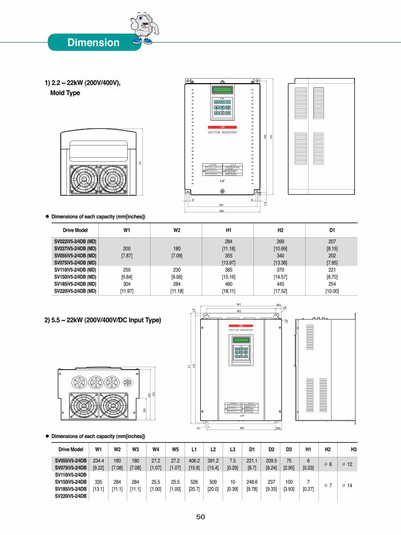
� � � � �� �
Dimension
1) 2.2 ~ 22kW (200V/400V), Mold Type
2) 5.5 ~ 22kW (200V/400V/DC Input Type)
W1
W2
L1 L2L3
W2H2
H3
W3 W5H1
D3
D2 D
1
● Dimensions of each capacity (mm[inches])
Drive Model W1 W2 W3 W4 W5 L1 L2 L3 D1 D2 D3 H1 H2 H3
SV055iV5-2/4DB 234.4 180 180 27.2 27.2 406.2 391.2 7.5 221.1 209.5 75 6 Ø 6 Ø 12 SV075iV5-2/4DB [9.22] [7.08] [7.08] [1.07] [1.07] [15.9] [15.4] [0.29] [8.7] [8.24] [2.95] [0.23]
SV110iV5-2/4DB SV150iV5-2/4DB 335 284 284 25.5 25.5 526 509 10 248.6 237 100 7
Ø 7 Ø 14 SV185iV5-2/4DB [13.1] [11.1] [11.1] [1.00] [1.00] [20.7] [20.0] [0.39] [9.78] [9.33] [3.93] [0.27] SV220iV5-2/4DB
● Dimensions of each capacity (mm[inches])
Drive Model W1 W2 H1 H2 D1
SV022iV5-2/4DB (MD) 284 269 207 SV037iV5-2/4DB (MD) 200 180 [11.18] [10.69] [8.15] SV055iV5-2/4DB (MD) [7.87] [7.09] 355 340 202 SV075iV5-2/4DB (MD) [13.97] [13.38] [7.95] SV110iV5-2/4DB (MD) 250 230 385 370 221 SV150iV5-2/4DB (MD) [9.84] [9.06] [15.16] [14.57] [8.70] SV185iV5-2/4DB (MD) 304 284 460 445 254 SV220iV5-2/4DB (MD) [11.97] [11.18] [18.11] [17.52] [10.00]
D1
W2
W1
99
7.5
H1
H2
7.5
50

3) 30 ~ 37kW (200V) 30 ~ 75kW (400V)30 ~ 75kW (DC Input Type)
STARVERT-iV5
D1
D2
STARVERT-iV5
W1
W2W3
W4
D3
D4
L1 L2
P1 P2
L3
L4
● Dimensions of each capacity (mm[inches])
Drive Model W1 W2 W3 W4 L1 L2 L3 D1 D2 D3 D4 P1 P2
SV300iV5-2/4 270 270 319 .2 350 635 660 680 120 197 256.6 308.2 16.9 8 SV370iV5-2/4 [10.6] [10.6] [12.5] [13.7] [25.0] [26.0] [26.7] [4.72] [7.76] [10.1] [12.1] [0.66] [0.31] SV450iV5-4 275 275 359.6 375 730.6 758.5 780 82.3 189.3 259 326 24.5 10.5 SV550iV5-4 SV750iV5-4 [10.8] [10.8] [14.1] [14.7] [28.7] [29.8] [30.7] [3.24] [7.45] [10.2] [12.8] [0.90] [0.41]
STARVERT-iV5
4) 90 ~ 160kW (400V)90 ~ 160kW (DC Input Type)
D1
D2
STARVERT-iV5
W1W2W3
D3D4P1 P2
L2
L1 L2 L3
● Dimensions of each capacity (mm[inches])
Drive Model W1 W2 W3 L1 L2 L3 D1 D2 D3 D4 P1 P2
SV900iV5-4 430 507 530 729 760 780 83.2 234.6 286.2 335 23.5 8.5 SV1100iV5-4 [16.9] [19.9] [20.8] [28.7] [29.9] [30.7] [3.27] [9.23] [11.2] [13.2] [0.92] [0.33] SV1320iV5-4 430 507 530 949 980 1000 95.2 231.6 298 345 23.5 8.5 SV1600iV5-4 [16.9] [19.9] [20.8] [37.3] [38.5] [39.3] [3.75] [9.12] [11.7] [13.5] [0.92] [0.33]
51
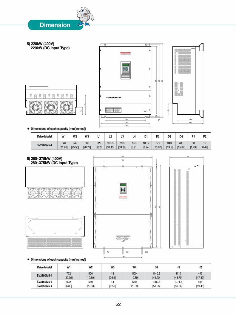
52
� � � � �� �
Dimension
5) 220kW (400V)220kW (DC Input Type)
D1
D2
L1 L2 L3
W1W2
W3
D3D4
P1P2
L4
● Dimensions of each capacity (mm[inches])
Drive Model W1 W2 W3 L1 L2 L3 L4 D1 D2 D3 D4 P1 P2
SV2200iV5-4 540 649 680 922 968.5 998 150 100.2 271 343 403 38 12 [21.26] [25.55] [26.77] [36.3] [38.13] [39.29] [5.91] [3.94] [10.67] [13.5] [15.87] [1.49] [0.47]
6) 280~375kW (400V)280~375kW (DC Input Type)
● Dimensions of each capacity (mm[inches])
Drive Model W1 W2 W3 W4 D1 H1 H2 SV2800iV5-4 772 500 13 500 1140.5 1110 442 [30.39] [19.69] [0.51] [19.69] [44.90] [43.70] [17.40] SV3150iV5-4 922 580 14 580 1302.5 1271.5 495 SV3750iV5-4 [6.30] [22.83] [0.55] [22.83] [51.28] [50.06] [19.49]
W1 D1
W2
W3 W3
W4
W3
H1
H2

53
8) 7.5 ~ 11kW (MRL)
7
680
97.2
64.7
666
310
330
7 7
7) 500kW (400V)500kW (DC Input Type)
● Dimensions of each capacity (mm[inches]) DC has a same dimension as AC.
Drive Model W1 W3 H1 D1 SV5000iV5-4 1200 1330 1260 550 [30.39] [44.90] [43.70] [17.40]
W
H1
H2
D

54
7
7 7
142.
2
700
686
355
375
100.
79) 15kW (MRL)
108.
5
700
686
375
355
75.7
7
7 7
10) 22kW (MRL)
� � � � �� �
Dimension
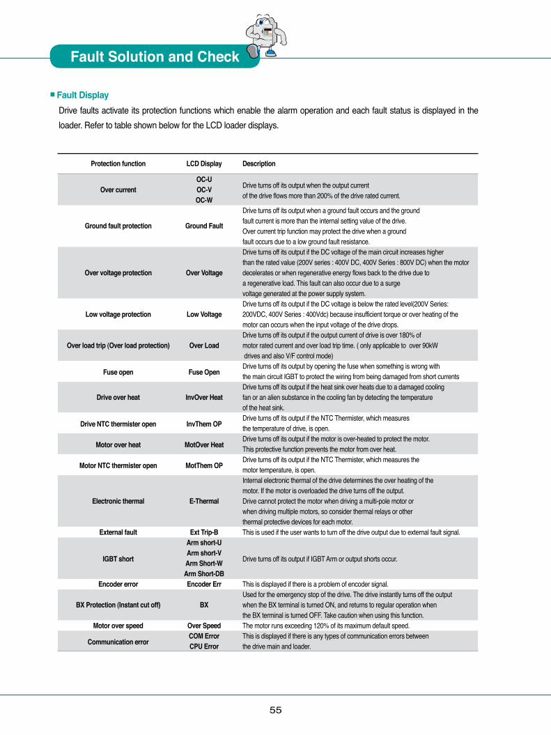
55
� � � � �� �
Fault Solution and Check
■Fault DisplayDrive faults activate its protection functions which enable the alarm operation and each fault status is displayed in the loader. Refer to table shown below for the LCD loader displays.
Protection function LCD Display Description
OC-U Drive turns off its output when the output current Over current OC-V of the drive flows more than 200% of the drive rated current. OC-W
Drive turns off its output when a ground fault occurs and the ground Ground fault protection Ground Fault fault current is more than the internal setting value of the drive. Over current trip function may protect the drive when a ground fault occurs due to a low ground fault resistance. Drive turns off its output if the DC voltage of the main circuit increases higher than the rated value (200V series : 400V DC, 400V Series : 800V DC) when the motor Over voltage protection Over Voltage decelerates or when regenerative energy flows back to the drive due to a regenerative load. This fault can also occur due to a surge voltage generated at the power supply system. Drive turns off its output if the DC voltage is below the rated level(200V Series: Low voltage protection Low Voltage 200VDC, 400V Series : 400Vdc) because insufficient torque or over heating of the motor can occurs when the input voltage of the drive drops. Drive turns off its output if the output current of drive is over 180% of Over load trip (Over load protection) Over Load motor rated current and over load trip time. ( only applicable to over 90kW drives and also V/F control mode)
Fuse open Fuse Open Drive turns off its output by opening the fuse when something is wrong with
the main circuit IGBT to protect the wiring from being damaged from short currents Drive turns off its output if the heat sink over heats due to a damaged cooling Drive over heat InvOver Heat fan or an alien substance in the cooling fan by detecting the temperature of the heat sink.
Drive NTC thermister open InvThem OP Drive turns off its output if the NTC Thermister, which measures
the temperature of drive, is open.
Motor over heat MotOver Heat Drive turns off its output if the motor is over-heated to protect the motor.
This protective function prevents the motor from over heat.
Motor NTC thermister open MotThem OP Drive turns off its output if the NTC Thermister, which measures the
motor temperature, is open. Internal electronic thermal of the drive determines the over heating of the motor. If the motor is overloaded the drive turns off the output. Electronic thermal E-Thermal Drive cannot protect the motor when driving a multi-pole motor or when driving multiple motors, so consider thermal relays or other thermal protective devices for each motor. External fault Ext Trip-B This is used if the user wants to turn off the drive output due to external fault signal. Arm short-U
IGBT short Arm short-V
Drive turns off its output if IGBT Arm or output shorts occur. Arm Short-W Arm Short-DB Encoder error Encoder Err This is displayed if there is a problem of encoder signal. Used for the emergency stop of the drive. The drive instantly turns off the output BX Protection (Instant cut off) BX when the BX terminal is turned ON, and returns to regular operation when the BX terminal is turned OFF. Take caution when using this function. Motor over speed Over Speed The motor runs exceeding 120% of its maximum default speed.
Communication error COM Error This is displayed if there is any types of communication errors between
CPU Error the drive main and loader.
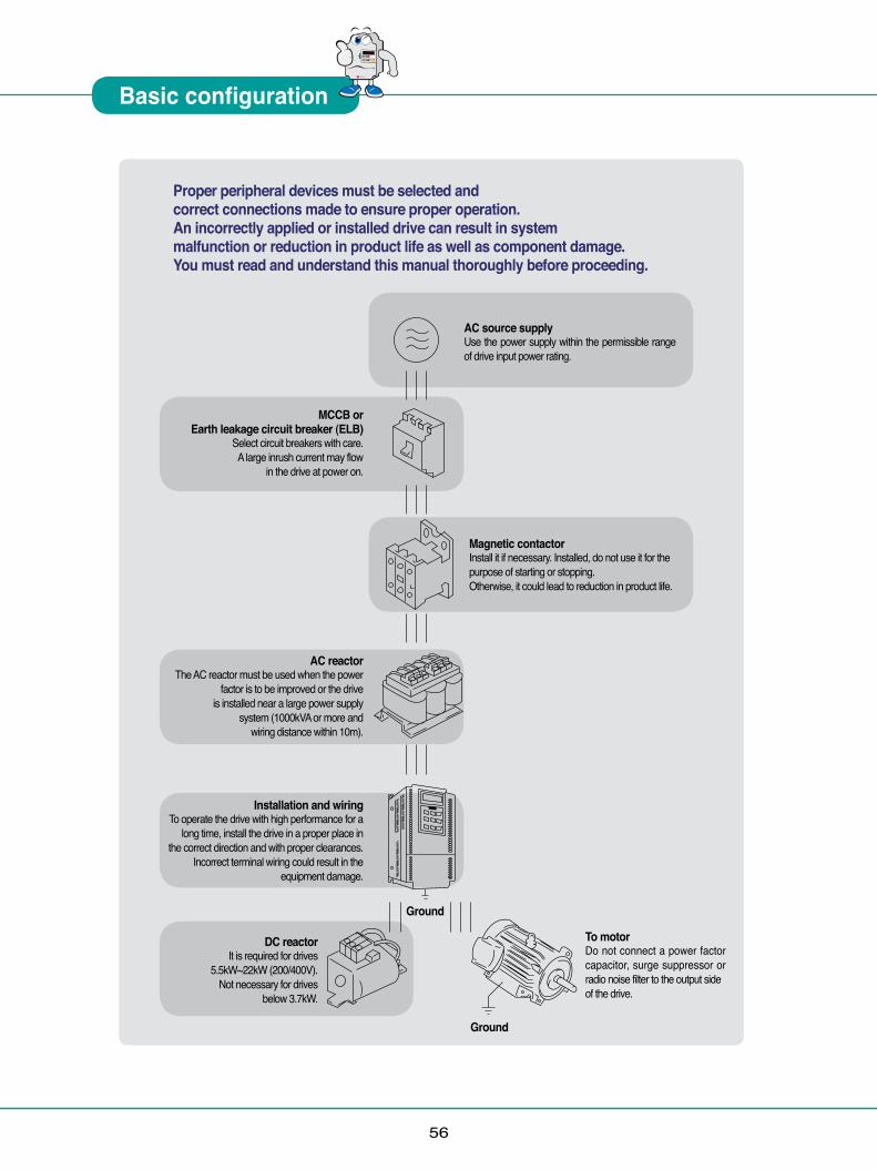
56
Basic configuration
� � � � �� �
Proper peripheral devices must be selected and correct connections made to ensure proper operation. An incorrectly applied or installed drive can result in system malfunction or reduction in product life as well as component damage. You must read and understand this manual thoroughly before proceeding.
Magnetic contactor Install it if necessary. Installed, do not use it for the purpose of starting or stopping. Otherwise, it could lead to reduction in product life.
MCCB or Earth leakage circuit breaker (ELB)
Select circuit breakers with care. A large inrush current may flow
in the drive at power on.
AC reactorThe AC reactor must be used when the power
factor is to be improved or the drive is installed near a large power supply
system (1000kVA or more and wiring distance within 10m).
Installation and wiringTo operate the drive with high performance for a
long time, install the drive in a proper place in the correct direction and with proper clearances.
Incorrect terminal wiring could result in the equipment damage.
DC reactorIt is required for drives
5.5kW~22kW (200/400V). Not necessary for drives
below 3.7kW.
AC source supply Use the power supply within the permissible range of drive input power rating.
To motor Do not connect a power factor capacitor, surge suppressor or radio noise filter to the output side of the drive.
Ground
Ground

57
� � � � �� �
Memo

58
� � � � �� �
Memo

59
www.lsis.com©2004.6 LSIS Co.,Ltd. All rights reserved.
Specifications in this catalog are subject to change without notice due to continuous product development and improvement.
■HEAD OFFICELS Tower, 127, LS-ro, Dongan-gu, Anyang-si, Gyeonggi-do,Korea
■EMEA +82-2-2034-4901 / [email protected]■Asia Pacific +82-2-2034-4375 / [email protected]
2014. 04 STARVERT iV5 (E) 2004. 06/(16) 2013. 10 Printed in Korea Pacomkorea
● LSIS (Middle East) FZE » Dubai, U.A.E. Address: LOB 19 JAFZA VIEW TOWER Room 205, Jebel Ali Freezone P.O. Box 114216, Dubai, United Arab Emirates Tel: 971-4-886 5360 Fax: 971-4-886-5361 e-mail: [email protected]
● Dalian LSIS Co., Ltd. » Dalian, ChinaAddress: No.15, Liaohexi 3-Road, Economic and Technical Development zone, Dalian 116600, ChinaTel: 86-411-8273-7777 Fax: 86-411-8730-7560 e-mail: [email protected]
● LSIS (Wuxi) Co., Ltd. » Wuxi, ChinaAddress: 102-A , National High & New Tech Industrial Development Area, Wuxi, Jiangsu, 214028, P.R.ChinaTel: 86-510-8534-6666 Fax: 86-510-522-4078 e-mail: [email protected]
● LSIS-VINA Co., Ltd. » Hanoi, VietnamAddress: Nguyen Khe - Dong Anh - Ha Noi - Viet NamTel: 84-4-882-0222 Fax: 84-4-882-0220 e-mail: [email protected]
● LSIS-VINA Co., Ltd. » Hochiminh , VietnamAddress: 41 Nguyen Thi Minh Khai Str. Yoco Bldg 4th Floor, Hochiminh City, VietnamTel: 84-8-3822-7941 Fax: 84-8-3822-7942 e-mail: [email protected]
● LSIS Tokyo Office » Tokyo, JapanAddress : 16th, Higashi-Kan, Akasaka Twin Tower, 2-17-22, Akasaka, Minato-ku, Tokyo, JapanTel: 81-3-3582-9128 Fax: 81-3-3582-2667 e-mail: [email protected]
● LSIS Shanghai Office » Shanghai, ChinaAddress: Room E-G, 12th Floor Huamin Empire Plaza, No.726, West Yan'an Road Shanghai 200050, P.R. ChinaTel: 86-21-5237-9977 (609) Fax: 89-21-5237-7191 e-mail: [email protected]
● LSIS Beijing Office » Beijing, ChinaAddress: B-Tower 17FL.Beijing Global Trade Center B/D. No.36, BeiSanHuanDong-Lu, DongCheng-District,Beijing 100013, P.R. ChinaTel: 86-10-5825-6025,7 Fax: 86-10-5825-6026 e-mail: [email protected]
● LSIS Guangzhou Office » Guangzhou, ChinaAddress: Room 1403,14F,New Poly Tower,2 Zhongshan Liu Road,Guangzhou, P.R. ChinaTel: 86-20-8326-6764 Fax: 86-20-8326-6287 e-mail: [email protected]
● LSIS Chengdu Office » Chengdu, ChinaAddress: Room 1701 17Floor, huanminhanjun internationnal Building, No1 Fuxing Road Chengdu, 610041, P.R. ChinaTel: 86-28-8670-3101 Fax: 86-28-8670-3203 e-mail: [email protected]
● LSIS Qingdao Office » Qingdao, China Address: 7B40,Haixin Guangchang Shenye Building B, No.9, Shandong Road Qingdao 26600, P.R. ChinaTel: 86-532-8501-6568 Fax: 86-532-583-3793 e-mail: [email protected]
■Global Network
● For your safety, please read user's manual thoroughly before operating.● Contact the nearest authorized service facility for examination, repair, or adjustment.● Please contact a qualified service technician when you need maintenance.
Do not disassemble or repair by yourself!● Any maintenance and inspection shall be performed by the personnel having expertise concerned.Safety Instructions
Related Documents


![High Precision &Torque Control STARVERT iV5 · encoder with open collector output and can divide the encoder pulse up ... SV [ ] [ ] [ ] iV5-4DC Maximum applicable ... Open loop control:](https://static.cupdf.com/doc/110x72/5b35a2b17f8b9aad388c0d1a/high-precision-torque-control-starvert-encoder-with-open-collector-output-and.jpg)