V22 Version Piezo Nano Motion - High Precision Micrometer/Strain Sensor -

Welcome message from author
This document is posted to help you gain knowledge. Please leave a comment to let me know what you think about it! Share it to your friends and learn new things together.
Transcript

V22 Version Piezo Nano Motion
- High Precision Micrometer/Strain Sensor -

288
High Precision Micrometer/Strain Sensor
The micrometers are
instruments with micrometer or millimeter measurement ranges with
nano-level accuracy. They are grouped into inductive, capacitive and laser types
and mainly used for high-precision measurement of length, thickness, depth, taper and other
applications. Piezo strain sensor is used for force process monitoring. When
subjected to deformation force, it outputs voltage signal.

289
Piezo·Nano·Motion
Microm
eter/Piezo S
train Sensor
High Precision Micrometer/Strain Sensor
Product List
Applications
Application
• Length (depth, height, thickness, diameter, taper) measurement • Vibration measurement • Precision positioning system
• Optical fiber alignment position detection • Micro-displacement detection • Micro-manipulation robot position detection
Type Appearance Measure mode Measuring range Characteristics Page
L.D1 LVDT Inductive 0~1mm
7-digit displayRS-232, RS-485 serial port
Peak hold functionVDC or 4~20mA output
290
E09.Cap Capacitive 0~200μmModular design
Optional multi-channel measure
291
LG-2MM Laser 0~2mm
+/-0.01%F.S. accuracyResolution to 7.6nm40kHz sampling rate
Up to 150 sensors integratedUSB2.0 interface
292
NSE2001 Piezoelectric 100με
Sensitivity 40mV/μεLow frequency lower limit
0.01HzTemperature -40~85°C
293
Surface Flatness Measurement
Type Appearance Measure mode Measuring range Characteristics Page
L.D1 LVDT Inductive 0~1mm
7-digit displayRS-232, RS-485 serial port
Peak hold functionVDC or 4~20mA output
2
E09.Cap Capacitive 0~200μmModular design
Optional multi-channel measure
3
LG-2MM Laser 0~2mm
+/-0.01%F.S. accuracyResolution to 7.6nm40kHz sampling rate
Up to 150 sensors integratedUSB2.0 interface
4
NSE2001 Piezoelectric 100με
Sensitivity 40mV/μεLow frequency lower limit
0.01HzTemperature -40~85° C
5
1
Microm
eter/Piezo S
train Sensor
290
7.45 Fully expand
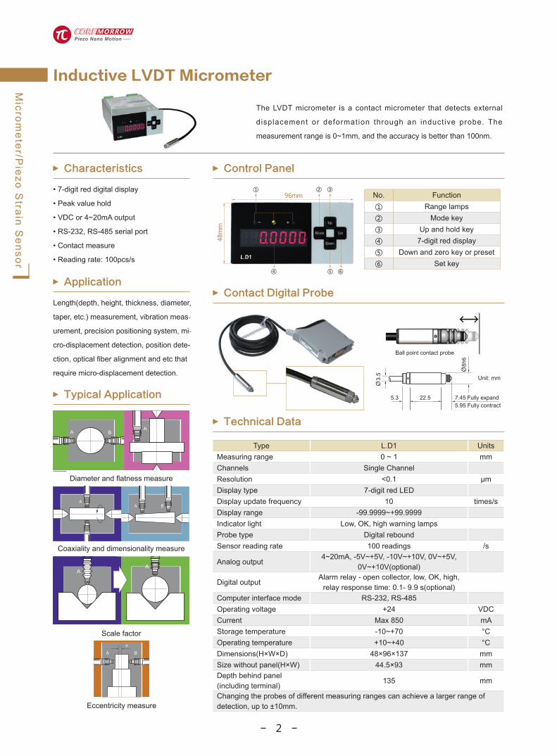
The LVDT micrometer is a contact micrometer that detects external
displacement or deformation through an inductive probe. The
measurement range is 0~1mm, and the accuracy is better than 100nm.
Inductive LVDT Micrometer
Typical Application
Characteristics
• 7-digit red digital display
• Peak value hold
• VDC or 4~20mA output
• RS-232, RS-485 serial port
• Contact measure
• Reading rate: 100pcs/s
Application
Length(depth, height, thickness, diameter,
taper, etc.) measurement, vibration meas-
urement, precision positioning system, mi-
cro-displacement detection, position dete-
ction, optical fiber alignment and etc that
require micro-displacement detection.
Control Panel
Technical DataA B
A
AA B
AA
e
Type L.D1 UnitsMeasuring range 0 ~ 1 mmChannels Single ChannelResolution <0.1 μmDisplay type 7-digit red LEDDisplay update frequency 10 times/sDisplay range -99.9999~+99.9999Indicator light Low, OK, high warning lamps Probe type Digital reboundSensor reading rate 100 readings /s
Analog output4~20mA, -5V~+5V, -10V~+10V, 0V~+5V,
0V~+10V(optional)
Digital outputAlarm relay - open collector, low, OK, high,
relay response time: 0.1- 9.9 s(optional)Computer interface mode RS-232, RS-485Operating voltage +24 VDCCurrent Max 850 mAStorage temperature -10~+70 °COperating temperature +10~+40 °CDimensions(H×W×D) 48×96×137 mmSize without panel(H×W) 44.5×93 mmDepth behind panel (including terminal)
135 mm
Changing the probes of different measuring ranges can achieve a larger range of detection, up to ±10mm.
No. Function① Range lamps② Mode key ③ Up and hold key④ 7-digit red display⑤ Down and zero key or preset⑥ Set key
Contact Digital Probe
Diameter and flatness measure
Coaxiality and dimensionality measure
Scale factor
Eccentricity measure
BA
Ball point contact probe
8h6
5.3 22.5
Unit: mm
5.95 Fully contract
3.5
291
Piezo·Nano·Motion
Microm
eter/Piezo S
train Sensor
E09.Cap capacitance non-contact micrometer can measure the small
displacement in the range of 0~200μm through the capacitance probe, the
measurement accuracy is nanometer level. The micrometer is composed of a
chassis and a sensing module, which can form a multi-channel measurement.
Capacitive CAP Micrometer
Typical Application
Characteristics
• Modular design, free combine
• Single board module available
• High resolution
• Analog output
• Non-contact measurement
Principle
It is based on the principle of an ideal parallel plate capacitor. The sensor and the measured target on the opposite side form two electrodes. The principle of guard ring capacitor is used to ensure that the sensor is sti l l l inear when measuring any metal.
Module Combination
Technical Data
Type E09.Cap Units
Measuring range 0~200 μm
Linearity ±0.1 μm
Static resolution 2.5 nm
Dynamic resolution(1kHz) 100 nm
Sensor diameter 10 mm
Minimum target diameter 10 mm
Static repeatability 5 nmSignal temperature stability
<0.005 %FSO/°C
Long-term stability <0.04 %FSO/month
Bandwidth 2 kHz(-3dB)
Operating temperature +10~+50 °C
Humidity <85 %
Voltage output 0~+10 V
Power supply 220VAC 50Hz±10%
Sensor cable length 1.6 m
Board size: L×H×D 35×130×180 mm
Chassis size: L×H×D 280×170×360 mm
Capacitance Probe
Vibration, amplitude, gap, beating
Displacement, distance, position, elongation
Deflection, deformation, waviness, inclination
Size, tolerance, identification
Distortion, deformation, axial vibration
Insulator thickness measur-ement
Appearance
Probe size
6-channel micrometer
Single channel micrometerChassis and power supply module
Sensing input interface
Voltage output interface
Sensing module
Online inspection, size inspection
Double-sided thickness detection
CAP-SERVO
SENSOR
CHANNEL 1
SENSORMONITOR
POWER
Conductive test surface
Uniform stable electric field
Ground wire protection
Non-contact measurement
Measuring electrode
Shielding electrode
Protect magnetic field
2

291
Piezo·Nano·Motion
Microm
eter/Piezo S
train Sensor
E09.Cap capacitance non-contact micrometer can measure the small
displacement in the range of 0~200μm through the capacitance probe, the
measurement accuracy is nanometer level. The micrometer is composed of a
chassis and a sensing module, which can form a multi-channel measurement.
Capacitive CAP Micrometer
Typical Application
Characteristics
• Modular design, free combine
• Single board module available
• High resolution
• Analog output
• Non-contact measurement
Principle
It is based on the principle of an ideal parallel plate capacitor. The sensor and the measured target on the opposite side form two electrodes. The principle of guard ring capacitor is used to ensure that the sensor is sti l l l inear when measuring any metal.
Module Combination
Technical Data
Type E09.Cap Units
Measuring range 0~200 μm
Linearity ±0.1 μm
Static resolution 2.5 nm
Dynamic resolution(1kHz) 100 nm
Sensor diameter 10 mm
Minimum target diameter 10 mm
Static repeatability 5 nmSignal temperature stability
<0.005 %FSO/°C
Long-term stability <0.04 %FSO/month
Bandwidth 2 kHz(-3dB)
Operating temperature +10~+50 °C
Humidity <85 %
Voltage output 0~+10 V
Power supply 220VAC 50Hz±10%
Sensor cable length 1.6 m
Board size: L×H×D 35×130×180 mm
Chassis size: L×H×D 280×170×360 mm
Capacitance Probe
Vibration, amplitude, gap, beating
Displacement, distance, position, elongation
Deflection, deformation, waviness, inclination
Size, tolerance, identification
Distortion, deformation, axial vibration
Insulator thickness measur-ement
Appearance
Probe size
6-channel micrometer
Single channel micrometerChassis and power supply module
Sensing input interface
Voltage output interface
Sensing module
Online inspection, size inspection
Double-sided thickness detection
CAP-SERVO
SENSOR
CHANNEL 1
SENSORMONITOR
POWER
Conductive test surface
Uniform stable electric field
Ground wire protection
Non-contact measurement
Measuring electrode
Shielding electrode
Protect magnetic field
3

Microm
eter/Piezo S
train Sensor
292
High precision, not limited by the material, texture, shape, and reflectivity of the measured object. It can measure from white to black, from metal to ceramics, and plastics, and non-contact measurement has no abrasion on the surface of the measured object. The modular structure is composed of three parts: USB interface module, power supply module and probe module. The probe modules can be assembled and cascaded for multi-channel measurement.
LG-2MM laser micrometer is a non-contact measuring instrument, its
measuring range is 2mm, the maximum measuring range can reach
10mm when changing different probes, and the static resolution can reach
7.6nm.
Laser Micrometer
Typical Application
Characteristics
• Laser measurement • Range 0~2mm • High precision • Non-contact measurement • Sampling frequency 40kHz
Principle Advantages
The principle of laser triangulation displacement measurement is to use a laser beam to focus on the surface of the object to be measured at a certain angle, and then image the laser spot on the object surface from another angle. Since the position of the laser irradiation point on the object surface is different, the angle of the scattered or reflected light is also different. With CCD photodetector measuring the position of the spot image, the angle of the chief ray can be calculated, and the height of the laser irradiation point on the surface of the object can be calculated. When the object moves along the direction of the laser line, the measurement result will change, so that the displacement of the object can be measured with the laser.
Technical Data
Type LG-2MM UnitsMeasuring range 0~2 mmReference distance 25 mmSpot size(diameter) 30 μm
LinearBest Typical
±%F.S.0.01 0.02
Repeatability(static) 20 40 nmRepeatability(dynamic) 100 200 nmResolution(static) 7.6 nmResolution(dynamic) 20 nmMax sampling frequency 40 kHzOutput frequency Max 4 kHz
Sampling period256/512 μs
1/2/4/8/16/32/64 ms
Bandwidth1300, 650, 325, 163,
81, 40, 20, 10, 5 Hz
Laser power <5 mWLaser class 3RLaser wavelength 670 nmAvailable modes Diffuse or mirrorOperating temperature 0~40 °CStorage temperature -20~70 °C
Humidity 10~95% No
condensationTemperature Coefficient ±0.05 % F.S./°C
Size of laser probe76.2×76.2×26.6
(Not include connector)mm
Mass 203 gPC communication USB2.0Power supply 24VDC/0.13A
Using Method & Size
The indicator lights show within the reference range8.05
76.27.14
3.76 dia.
32.54
61.01
76.2
26.610.4
16.6
Laser BeamInterval time setting characteristics
The reading with setting interval time
The reading wi thout setting interval time
Mirror modeDiffuse mode
Axis motion measure
Motor vibration measure
Diameter measure Thickness measure Amplitude measure Runout measure
Depth measure Distance measure
Thickness measure Metal thickness measure
293
Piezo·Nano·Motion
Microm
eter/Piezo S
train Sensor
Parameter Typical value Units
Measurement parameters
Deformation in the direction of the longer axis
Sensitivity 40mV/µε at room temperature+20%/-10%
PolarityPositive voltage when
tension is appliedLow frequency lower limit 0.01 HzResonant frequency 14.7 kHzDynamic range 100 µεConnector Coaxial 10-32 UNFPower current 4(min 2, max 20) mADC bias voltage 12(min 8, max 14) VDC bias stable 60 sMounting thread M6×20, tapered headMounting torque 5(min 3, max 10) NmOperating temperature -40~+85 °CMass 50 g±5%
Strain sensors are mainly used to measure the deformation of a structural surface.
Generally, during the entire process of applying force, the mechanical load-bearing
structure will be strained by a tensile or compressive force greater or lesser than the
required force. The strain sensor can perform indirect dynamic and quasi-static force
measurement on it, and the relationship between the force and strain is linear enough to
effectively meet the requirements of accurate measurement and monitoring. When using
strain for indirect measurement, the force split can be close to 99%, much higher than
direct measurement.
Strain sensors can be used for process monitoring of force, such as welding force
monitoring. The sensor is equipped with electronics and IEPE interface. The converter
type is 10-32UNF.
A. The measured mechanical structure is used to be
stretched or compressed cyclically.
B. The two contact feet (yellow area) of the strain sensor
transmit the structural strain to the sensor and the piezo
element through friction to measure the shear force.
C . Piezo measuring element generates an electric charge
proportional to the applied shear force.
D. The sensor housing or body, similar to a spring,
converts strain into a corresponding proportional force.
Piezo Strain Sensor
Characteristics
• Sensitivity: 40mV/με • Lower limit of low frequency: 0.01Hz • Acceleration compensation • Application: process monitor of force
Mounting & Force Monitor
Structure Technical Data
Drawing
17
5
Ø6.3
Ø40
15.2
Tensile strainCompressive strain
4

293
Piezo·Nano·Motion
Microm
eter/Piezo S
train Sensor
Parameter Typical value Units
Measurement parameters
Deformation in the direction of the longer axis
Sensitivity 40mV/µε at room temperature+20%/-10%
PolarityPositive voltage when
tension is appliedLow frequency lower limit 0.01 HzResonant frequency 14.7 kHzDynamic range 100 µεConnector Coaxial 10-32 UNFPower current 4(min 2, max 20) mADC bias voltage 12(min 8, max 14) VDC bias stable 60 sMounting thread M6×20, tapered headMounting torque 5(min 3, max 10) NmOperating temperature -40~+85 °CMass 50 g±5%
Strain sensors are mainly used to measure the deformation of a structural surface.
Generally, during the entire process of applying force, the mechanical load-bearing
structure will be strained by a tensile or compressive force greater or lesser than the
required force. The strain sensor can perform indirect dynamic and quasi-static force
measurement on it, and the relationship between the force and strain is linear enough to
effectively meet the requirements of accurate measurement and monitoring. When using
strain for indirect measurement, the force split can be close to 99%, much higher than
direct measurement.
Strain sensors can be used for process monitoring of force, such as welding force
monitoring. The sensor is equipped with electronics and IEPE interface. The converter
type is 10-32UNF.
A. The measured mechanical structure is used to be
stretched or compressed cyclically.
B. The two contact feet (yellow area) of the strain sensor
transmit the structural strain to the sensor and the piezo
element through friction to measure the shear force.
C . Piezo measuring element generates an electric charge
proportional to the applied shear force.
D. The sensor housing or body, similar to a spring,
converts strain into a corresponding proportional force.
Piezo Strain Sensor
Characteristics
• Sensitivity: 40mV/με • Lower limit of low frequency: 0.01Hz • Acceleration compensation • Application: process monitor of force
Mounting & Force Monitor
Structure Technical Data
Drawing
17
5
Ø6.3
Ø40
15.2
Tensile strainCompressive strain
5

Harbin Core Tomorrow Science & Technology Co., Ltd.Tel:+86-451-86268790 +86-18944636468Fax:0451-86267847Postcode:150086Email:[email protected]:www.coremorrow.comAddress:Building I2, No.191 Xuefu Road, Nangang District, Harbin Wechat CTO
Related Documents