HIGH POWER TEST OF RF SEPARATOR FOR 12 GEV UPGRADE OF CEBAF AT JEFFERSON LAB * S. Ahmed , M. Wissmann, J. Mammosser, M. Spata, C. Hovater, † Thomas Jefferson National Accelerator Facility, Newport News, VA 23606, USA G.A. Krafft, J.R. Delayen, Thomas Jefferson National Accelerator Facility, Newport News, VA 23606, USA Center for Accelerator Science, Old Dominion University, Norfolk, VA 23529, USA Abstract CEBAF at Jefferson Lab is in the process of an energy upgrade from 6 GeV to 12 GeV. The existing setup of the RF separator cavities in the 5th pass will not be adequate to extract the 11 GeV beam to any two existing experimen- tal halls (A, B or C) while simultaneously delivering 12 GeV beam to the new hall D. To restore this capability, we are exploring the possibility of using existing normal con- ducting 499 MHz TEM-type rf separator cavities. Detailed numerical studies suggest that six 2-cell normal conduct- ing structures meet the requirement. Each 2-cell structure will require up to 4 kW RF input power in contrast with the current nominal operating power of 1.0 to 2.0 kW. A high power test at 4 kW confirmed that the cavity can meet the requirement. INTRODUCTION The Continuous Electron Beam Accelerator Facility (CEBAF) at Jefferson Lab is in the process of an energy upgrade from 6 GeV to 12 GeV. Beam extraction in the ex- isting setup is done with a system consisting of ten normal conducting RF separator cavities. Each structure consists of two cells (see Fig. 1) – details are very well discussed in [1]. RF is powered from one end using a loop coupler which couples to the other cell via two holes in the cen- tral plate. The parameters of the cavity are summarized in Table 1. In the current setup, a series array of three cavi- ties on the 5th pass is capable of sending highest energy (6 GeV) beams to the three existing experimental halls A, B, and C simultaneously. For 12 GeV operation of CEBAF, the RF separator cavities are supposed to provide deflec- tions of ∼±452 μrad for 11 GeV beams traveling to halls A and C. The RF kick is determined by the requirement to have the beams to halls A and C vertically separated by ±17 mm relative to hall B at the entrance of the existing extraction magnet (Lambertson-style) in the beam switch- yard located 43 m downstream from the start of the separa- tor cavity. Beam dynamics simulations suggest the use of six 2-cell normal conducting cavities [2] in order to restore * Authored by Jefferson Science Associates, LLC under U.S. DOE Contract No. DE-AC05-06OR23177. The U.S. Government re- tains a non-exclusive,paid-up, irrevocable, world-wide license to pub- lish or reproduce this manuscript for U.S. Government purposes. † [email protected] this capability. Each 2-cell system needs to operate at the power level of ∼ 4 kW in contrast with the current nom- inal power of 1.0-2.0 kW [3]. This increase in RF power can increase heat load which may detune the cavity – lead- ing to instabilities. It is therefore important to confirm the cavity’s operating ability at the elevated power level. Figure 1: Schematic of normal conducting RF separator. Table 1: Parameters of Cavity Parameters Unit Value Operating Mode TEM R/Q MΩ 210 Q L 2500 Q 0 5000 Operating Frequency MHz 499 Rod Separation mm 14.3 EXPERIMENTAL SETUP To assemble a new separator cavity, end and central cop- per plates were taken from an existing prototype structure and assembled on a new stainless steel body. The stain- less steel bodies and other components were cleaned for ultra high vacuum. The cavity was then assembled in a clean room – see Fig. 2. The S 21 measurement for criti- cal coupling of power gives Q L ∼ 2600 – see Fig. 3. In this transmission measurement, field probe coupler was set to -40 dB. A helium leak test was performed to confirm THPPR030 Proceedings of IPAC2012, New Orleans, Louisiana, USA ISBN 978-3-95450-115-1 4032 Copyright c ○ 2012 by IEEE – cc Creative Commons Attribution 3.0 (CC BY 3.0) — cc Creative Commons Attribution 3.0 (CC BY 3.0) 06 Instrumentation, Controls, Feedback and Operational Aspects T22 Reliability, Operability

Welcome message from author
This document is posted to help you gain knowledge. Please leave a comment to let me know what you think about it! Share it to your friends and learn new things together.
Transcript

HIGH POWER TEST OF RF SEPARATOR FOR 12 GEV UPGRADE OFCEBAF AT JEFFERSON LAB ∗
S. Ahmed , M. Wissmann, J. Mammosser, M. Spata, C. Hovater,†
Thomas Jefferson National Accelerator Facility, Newport News, VA 23606, USAG.A. Krafft, J.R. Delayen,
Thomas Jefferson National Accelerator Facility, Newport News, VA 23606, USACenter for Accelerator Science, Old Dominion University, Norfolk, VA 23529, USA
Abstract
CEBAF at Jefferson Lab is in the process of an energyupgrade from 6 GeV to 12 GeV. The existing setup of theRF separator cavities in the 5th pass will not be adequateto extract the 11 GeV beam to any two existing experimen-tal halls (A, B or C) while simultaneously delivering 12GeV beam to the new hall D. To restore this capability, weare exploring the possibility of using existing normal con-ducting 499 MHz TEM-type rf separator cavities. Detailednumerical studies suggest that six 2-cell normal conduct-ing structures meet the requirement. Each 2-cell structurewill require up to 4 kW RF input power in contrast with thecurrent nominal operating power of 1.0 to 2.0 kW. A highpower test at 4 kW confirmed that the cavity can meet therequirement.
INTRODUCTION
The Continuous Electron Beam Accelerator Facility(CEBAF) at Jefferson Lab is in the process of an energyupgrade from 6 GeV to 12 GeV. Beam extraction in the ex-isting setup is done with a system consisting of ten normalconducting RF separator cavities. Each structure consistsof two cells (see Fig. 1) – details are very well discussedin [1]. RF is powered from one end using a loop couplerwhich couples to the other cell via two holes in the cen-tral plate. The parameters of the cavity are summarized inTable 1. In the current setup, a series array of three cavi-ties on the 5th pass is capable of sending highest energy (6GeV) beams to the three existing experimental halls A, B,and C simultaneously. For 12 GeV operation of CEBAF,the RF separator cavities are supposed to provide deflec-tions of ∼ ±452 µrad for 11 GeV beams traveling to hallsA and C. The RF kick is determined by the requirementto have the beams to halls A and C vertically separated by±17 mm relative to hall B at the entrance of the existingextraction magnet (Lambertson-style) in the beam switch-yard located 43 m downstream from the start of the separa-tor cavity. Beam dynamics simulations suggest the use ofsix 2-cell normal conducting cavities [2] in order to restore
∗ Authored by Jefferson Science Associates, LLC under U.S. DOEContract No. DE-AC05-06OR23177. The U.S. Government re-tains a non-exclusive,paid-up, irrevocable, world-wide license to pub-lish or reproduce this manuscript for U.S. Government purposes.†[email protected]
this capability. Each 2-cell system needs to operate at thepower level of ∼ 4 kW in contrast with the current nom-inal power of 1.0-2.0 kW [3]. This increase in RF powercan increase heat load which may detune the cavity – lead-ing to instabilities. It is therefore important to confirm thecavity’s operating ability at the elevated power level.
Figure 1: Schematic of normal conducting RF separator.
Table 1: Parameters of Cavity
Parameters Unit Value
Operating Mode TEMR/Q MΩ 210QL 2500Q0 5000Operating Frequency MHz 499Rod Separation mm 14.3
EXPERIMENTAL SETUPTo assemble a new separator cavity, end and central cop-
per plates were taken from an existing prototype structureand assembled on a new stainless steel body. The stain-less steel bodies and other components were cleaned forultra high vacuum. The cavity was then assembled in aclean room – see Fig. 2. The S 21 measurement for criti-cal coupling of power gives QL ∼ 2600 – see Fig. 3. Inthis transmission measurement, field probe coupler was setto -40 dB. A helium leak test was performed to confirm
THPPR030 Proceedings of IPAC2012, New Orleans, Louisiana, USA
ISBN 978-3-95450-115-1
4032Cop
yrig
htc
2012
byIE
EE
–cc
Cre
ativ
eC
omm
onsA
ttri
butio
n3.
0(C
CB
Y3.
0)—
ccC
reat
ive
Com
mon
sAtt
ribu
tion
3.0
(CC
BY
3.0)
06 Instrumentation, Controls, Feedback and Operational Aspects
T22 Reliability, Operability

Figure 2: Clean room assembly of separator cavity.
Figure 3: Low level measurement for critical coupling.
that the cavity is leak tight. We connected the scroll andturbo pumps to the cavity which pumped down to 10−6 torr.The ion pump was started with 4 kV and then turned to7 kV when the pressure reached to 6×10⁻⁸ torr. Runningthe ion pump for two days brought down the pressure to4× 10−9 torr. The cavity was then moved to the acceleratorsite where an rf power source and water cooling setup wereavailable. The water cooling manifold used in this experi-ment conforms to a parallel configuration of water distribu-tion through different sections of the cavity. A schematic of
Figure 4: Schematic of high power test.
Figure 5: Experimental setup for high power test.
high power test is shown in Fig. 4 and the real experimentalsetup following the schematic is illustrated in Fig. 5.
Proceedings of IPAC2012, New Orleans, Louisiana, USA THPPR030
06 Instrumentation, Controls, Feedback and Operational Aspects
T22 Reliability, Operability
ISBN 978-3-95450-115-1
4033 Cop
yrig
htc
2012
byIE
EE
–cc
Cre
ativ
eC
omm
onsA
ttri
butio
n3.
0(C
CB
Y3.
0)—
ccC
reat
ive
Com
mon
sAtt
ribu
tion
3.0
(CC
BY
3.0)
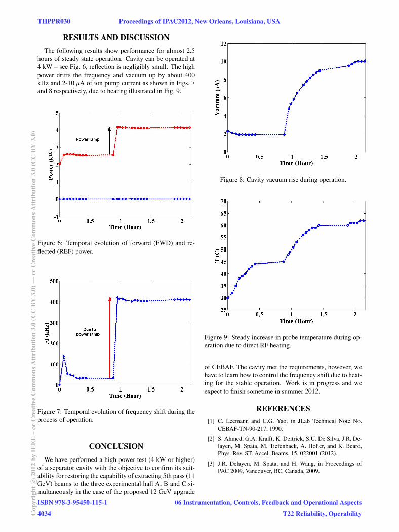
RESULTS AND DISCUSSIONThe following results show performance for almost 2.5
hours of steady state operation. Cavity can be operated at4 kW – see Fig. 6, reflection is negligibly small. The highpower drifts the frequency and vacuum up by about 400kHz and 2-10 µA of ion pump current as shown in Figs. 7and 8 respectively, due to heating illustrated in Fig. 9.
Figure 6: Temporal evolution of forward (FWD) and re-flected (REF) power.
Figure 7: Temporal evolution of frequency shift during theprocess of operation.
CONCLUSIONWe have performed a high power test (4 kW or higher)
of a separator cavity with the objective to confirm its suit-ability for restoring the capability of extracting 5th pass (11GeV) beams to the three experimental hall A, B and C si-multaneously in the case of the proposed 12 GeV upgrade
Figure 8: Cavity vacuum rise during operation.
Figure 9: Steady increase in probe temperature during op-eration due to direct RF heating.
of CEBAF. The cavity met the requirements, however, wehave to learn how to control the frequency shift due to heat-ing for the stable operation. Work is in progress and weexpect to finish sometime in summer 2012.
REFERENCES[1] C. Leemann and C.G. Yao, in JLab Technical Note No.
CEBAF-TN-90-217, 1990.
[2] S. Ahmed, G.A. Krafft, K. Deitrick, S.U. De Silva, J.R. De-layen, M. Spata, M. Tiefenback, A. Hofler, and K. Beard,Phys. Rev. ST. Accel. Beams, 15, 022001 (2012).
[3] J.R. Delayen, M. Spata, and H. Wang, in Proceedings ofPAC 2009, Vancouver, BC, Canada, 2009.
THPPR030 Proceedings of IPAC2012, New Orleans, Louisiana, USA
ISBN 978-3-95450-115-1
4034Cop
yrig
htc
2012
byIE
EE
–cc
Cre
ativ
eC
omm
onsA
ttri
butio
n3.
0(C
CB
Y3.
0)—
ccC
reat
ive
Com
mon
sAtt
ribu
tion
3.0
(CC
BY
3.0)
06 Instrumentation, Controls, Feedback and Operational Aspects
T22 Reliability, Operability
Related Documents