High Performance Equipment Filters For General Purpose and Switched Mode Power Supply Applications

Welcome message from author
This document is posted to help you gain knowledge. Please leave a comment to let me know what you think about it! Share it to your friends and learn new things together.
Transcript
High PerformanceEquipment Filters
For General Purpose and Switched ModePower Supply Applications
Introduction
MPE’s reputation as one of Europe’s leading filterspecialists is based on over 65 years experience inthe design, development, and production of highperformance radio frequency interference filters andcustom capacitors. Our commitment to a policy ofcontinuous product development and innovationhas resulted in one of the most comprehensiveranges of filter products available from a singlemanufacturer.
The latest filter technology has been developed andadapted to new requirements by maintainingcontinuous close liaison with Defence Contractorsand commercial organisations both in the UK andabroad. Our unrivalled capability and experienceenables us to design and build filters to suit almostany application.
In addition to the equipment filters covered by thiscatalogue, standard ranges of filter productsmanufactured by MPE cover designs with currentratings up to 2400A, voltages up to 440V, andmodular precision filters for telephone, data, andcontrol lines.
Capacitor products range from close tolerance,miniature, designs for military telecommunicationsequipment to very high voltage X-Ray capacitorstested to 200,000 volts.
Non-standard requirements can be fulfilled by acustom designed filter or capacitor from a verydiverse range and capability also offered by MPE.
Apart from many individual vendor approvals bycustomers, MPE holds the following major factoryaccreditations:
* NATO AQAP-1* BS5750 Part 1 / ISO9001 / EN29001* BS9000 approval* CECC approval* Member of Industrial TEMPEST Scheme
Contents
© MPE LIMITED June 1994
High Performance Equipment Filters
1
ContentsPage No. Voltage Rating Current Rating
General Purpose Filters - DC
General Purpose Filters - AC
General Purpose Filters - Introduction
Introduction & Contents1
2
3
5
7
9
11
12
-
-
1 - 15A
1 - 15A
-
1 - 15 A
-
-
-
-
100V DC
240V AC50/60Hz
240V AC50/60Hz
-
-
-
Mains Input Filters for SwitchedMode Power Supplies
Mains Input Filters for SwitchedMode Power Supplies - Introduction
Installation Details & Safety
Custom Design Service
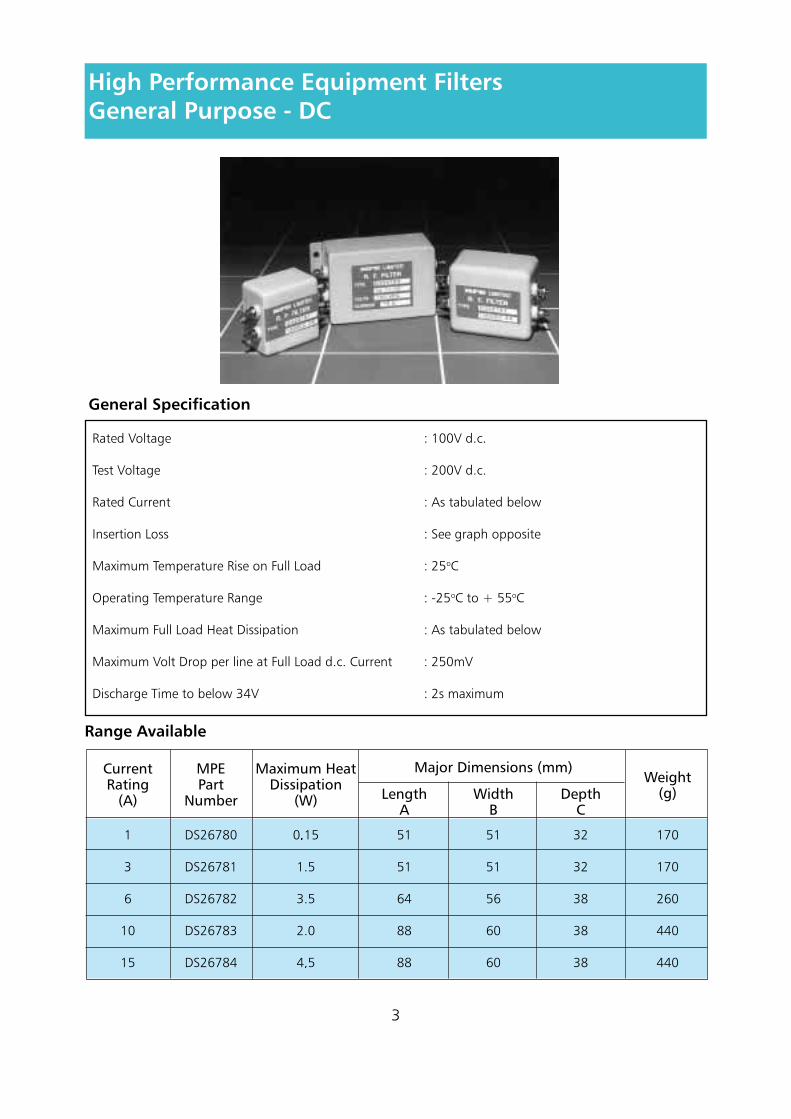
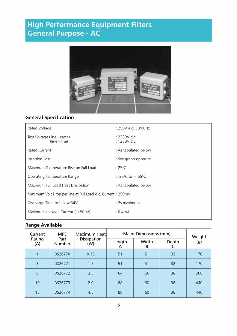
These ranges of equipment filters are intended forgeneral purpose applications where highperformance over a wide range of frequencies isrequired. Separate ranges are offered for a.c. andd.c. applications.
High performance is achieved through the use ofMPE’s proprietary feedthrough capacitors andbulkhead mounting design, which enable goodfiltering performance to be achieved to 1GHz andbeyond. The feedthrough capacitors will also providegreater immunity of the equipment to highfrequency transients than is usually provided bygeneral purpose filters.
Most general purpose equipment filters do not usefeedthrough capacitors and are not designed forbulkhead mounting, which limits their usefulperformance above about 1MHz. Above thisfrequency, the performance will drop off rapidly due
to the capacitors going into self resonance. This canbe a severe disadvantage as the European EMCdirective will require equipment to be fullysuppressed to at least 30MHz and filters not usingfeedthrough capacitors may not offer sufficientperformance. Some existing specifications alreadyrequire suppression up to 1GHz and this is likely tobe the increasing trend.
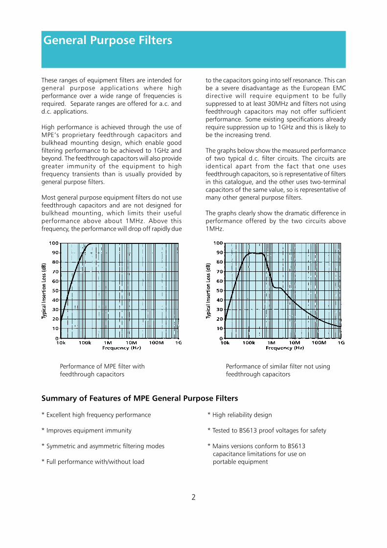
The graphs below show the measured performanceof two typical d.c. filter circuits. The circuits areidentical apart from the fact that one usesfeedthrough capacitors, so is representative of filtersin this catalogue, and the other uses two-terminalcapacitors of the same value, so is representative ofmany other general purpose filters.
The graphs clearly show the dramatic difference inperformance offered by the two circuits above1MHz.
Performance of MPE filter with Performance of similar filter not usingfeedthrough capacitors feedthrough capacitors
Summary of Features of MPE General Purpose Filters
* Excellent high frequency performance * High reliability design
* Improves equipment immunity * Tested to BS613 proof voltages for safety
* Symmetric and asymmetric filtering modes * Mains versions conform to BS613 capacitance limitations for use on
* Full performance with/without load portable equipment
2
General Purpose Filters
General Specification
Rated Voltage : 100V d.c.
Test Voltage : 200V d.c.
Rated Current : As tabulated below
Insertion Loss : See graph opposite
Maximum Temperature Rise on Full Load : 25oC
Operating Temperature Range : -25oC to + 55oC
Maximum Full Load Heat Dissipation : As tabulated below
Maximum Volt Drop per line at Full Load d.c. Current : 250mV
Discharge Time to below 34V : 2s maximum
3
High Performance Equipment FiltersGeneral Purpose - DC
Range Available
1
3
6
10
15
DS26780
DS26781
DS26782
DS26783
DS26784
0.15
1.5
3.5
2.0
4.5
51
51
64
88
88
51
51
56
60
60
32
32
38
38
38
170
170
260
440
440
CurrentRating
(A)
MPEPart
Number
Maximum HeatDissipation
(W) LengthA
WidthB
Major Dimensions (mm)
DepthC
Weight(g)
4
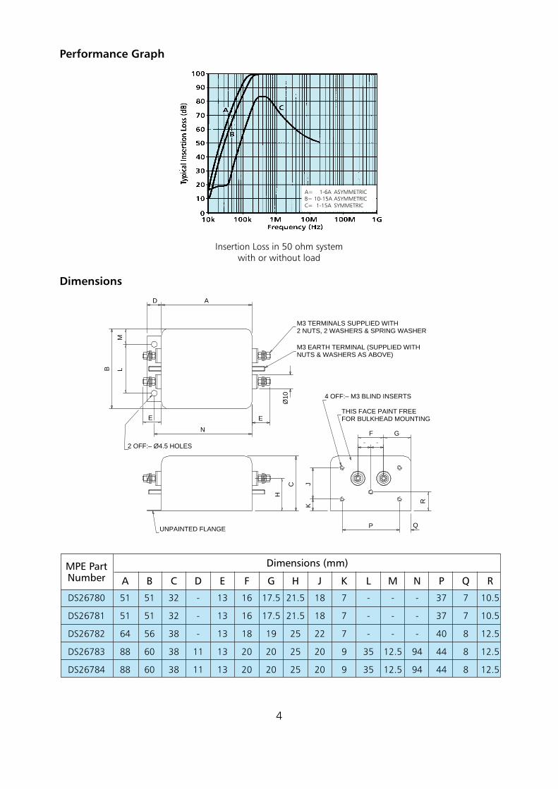
Performance Graph
Insertion Loss in 50 ohm systemwith or without load
Dimensions
D A
B LM
E
N
E
Ø10
F G
R
QP
JK
H
C
M3 TERMINALS SUPPLIED WITH2 NUTS, 2 WASHERS & SPRING WASHER
M3 EARTH TERMINAL (SUPPLIED WITHNUTS & WASHERS AS ABOVE)
4 OFF:– M3 BLIND INSERTS
THIS FACE PAINT FREEFOR BULKHEAD MOUNTING
UNPAINTED FLANGE
2 OFF:– Ø4.5 HOLES
DS26780
DS26781
DS26782
DS26783
DS26784
51
51
64
88
88
MPE PartNumber A
51
51
56
60
60
B
32
32
38
38
38
C
-
-
-
11
11
D
13
13
13
13
13
E
16
16
18
20
20
F
17.5
17.5
19
20
20
G
21.5
21.5
25
25
25
H
18
18
22
20
20
J
7
7
7
9
9
K
-
-
-
35
35
L
-
-
-
12.5
12.5
M
-
-
-
94
94
N
37
37
40
44
44
P
7
7
8
8
8
Q
10.5
10.5
12.5
12.5
12.5
R
Dimensions (mm)
A= 1-6A ASYMMETRICB= 10-15A ASYMMETRICC= 1-15A SYMMETRIC
5
Range Available
Rated Voltage : 250V a.c. 50/60Hz
Test Voltage (line - earth) : 2250V d.c. (line - line) : 1250V d.c.
Rated Current : As tabulated below
Insertion Loss : See graph opposite
Maximum Temperature Rise on Full Load : 25oC
Operating Temperature Range : -25oC to + 55oC
Maximum Full Load Heat Dissipation : As tabulated below
Maximum Volt Drop per line at Full Load d.c. Current : 250mV
Discharge Time to below 34V : 2s maximum
Maximum Leakage Current (at 50Hz) : 0.4mA
High Performance Equipment FiltersGeneral Purpose - AC
General Specification
1
3
6
10
15
DS26770
DS26771
DS26772
DS26773
DS26774
0.15
1.5
3.5
2.0
4.5
51
51
64
88
88
51
51
56
60
60
32
32
38
38
38
170
170
260
440
440
CurrentRating
(A)
MPEPart
Number
Maximum HeatDissipation
(W) LengthA
WidthB
Major Dimensions (mm)
DepthC
Weight(g)
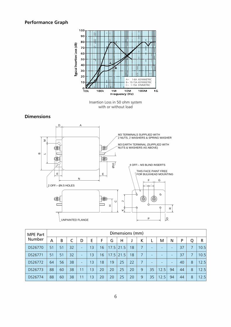
Performance Graph
Insertion Loss in 50 ohm systemwith or without load
Dimensions
6
D A
B LM
E
N
E
Ø10
F G
R
QP
JK
H
C
M3 TERMINALS SUPPLIED WITH2 NUTS, 2 WASHERS & SPRING WASHER
M3 EARTH TERMINAL (SUPPLIED WITHNUTS & WASHERS AS ABOVE)
4 OFF:– M3 BLIND INSERTS
THIS FACE PAINT FREEFOR BULKHEAD MOUNTING
UNPAINTED FLANGE
2 OFF:– Ø4.5 HOLES
DS26770
DS26771
DS26772
DS26773
DS26774
51
51
64
88
88
MPE PartNumber A
51
51
56
60
60
B
32
32
38
38
38
C
-
-
-
11
11
D
13
13
13
13
13
E
16
16
18
20
20
F
17.5
17.5
19
20
20
G
21.5
21.5
25
25
25
H
18
18
22
20
20
J
7
7
7
9
9
K
-
-
-
35
35
L
-
-
-
12.5
12.5
M
-
-
-
94
94
N
37
37
40
44
44
P
7
7
8
8
8
Q
10.5
10.5
12.5
12.5
12.5
R
Dimensions (mm)
A= 1-6A ASYMMETRICB= 10-15A ASYMMETRICC= 1-15A SYMMETRIC
When considering published performance figuresfor filters, the insertion loss will invariably be quotedin a 50 ohm system. This is because, historically, 50ohms was considered to be representative of mostpractical situations, and measurement specificationswere written around this impedance.
In practice, many systems have an impedancedifferent from 50 ohms. Switched mode powersupplies are a common application requiring filteringwhere the impedance is not 50 ohms. In fact, aswitched mode power supply (SMPS) will usuallypresent a very low impedance to the filter.
For such applications, a filter performance measuredin a 50 ohm system can be very misleading as it isunlikely to represent the attenuation which will beachieved when the filter is connected in circuit.
Many simple general purpose filter designs, althoughoffering reasonable performance in a 50 ohmsystem, will offer little or no insertion loss whenpresented with a low impedance interference sourcesuch as a SMPS. A more specialised filter circuittherefore needs to be considered.
The problem arises due to the operating principlesof the SMPS. The SMPS circuit will normally operateat a switching frequency of between 20kHz and200kHz. This will generate unwanted RFI at theswitching frequency and its numerous harmonicsoften up to several hundred MHz.
RFI noise is generated by the SMPS both in theasymmetric mode (each line to earth) and symmetricmode (live to neutral), the symmetric mode noisebeing predominant at the lower frequencies, up toa few hundred kHz, and the asymmetric mode noisebeing predominant at higher frequencies aboveabout 1MHz.
Because the switching operation of the SMPS appliesalmost a short circuit across the line, the sourceimpedance of the RFI generated by the SMPS is verylow, typically 0.1 ohm, and this is the impedancepresented to the filter. The other end of the filterwill be facing the mains supply which is likely tohave an impedance in the order of 50 - 100 ohmsover the range of frequencies of interest.
In order to obtain good filter performance, it isnecessary to achieve as great as possible animpedance mismatch between each end of the filterand the system in which it operates.
Part of the solution is to use a filter which has beenspecifically designed to operate in the practicalsystem impedance. Such a filter design will have aninductive input to face the low impedance of theSMPS and a capacitive output to face the higherimpedance of the mains supply.
A second requirement for a filter designed speciallyfor use with switched mode power supplies is goodsymmetric mode performance which must, ofcourse, be provided in the special impedance system.
Finally, if the noise generated by the SMPS extendsinto frequencies beyond a few MHz, then the two-terminal capacitors normally used in most types ofgeneral purpose filter may not be adequate as theywill go into resonance and lose performance abovea few MHz. For EMC specifications which specifynoise levels up to 30MHz, this can be a problem,especially if the SMPS is particularly noisy.
A filter design incorporating feedthrough capacitorsthen needs to be used. This is even more importantif the specification requirement extends beyond30MHz which is the increasing tendency. The filtersshould be bulkhead mounted to ensure maximumfilter performance is obtained.
7
Why have Special Filters for Switched Mode Power Supplies?
Mains Input Filters for Switched Mode Power Supplies
Based on experience gained from testing andproviding filtering solutions for numerous types ofswitched mode power supplies over a number ofyears, MPE has developed a range of mains inputfilters specifically for switched mode power supplies.
These filters feature all of the benefits of the generalpurpose filters described on previous pages but alsoincorporate the circuitry required to provide effectivesuppression under the special impedance conditionspresented by the switched mode power supply forboth modes of interference.
The standard range of filters detailed on thefollowing pages has a mains input rating of 240V50/60Hz with current ratings of 1, 3, 6, 10, and 15amps.
Insertion loss performance is quoted both in theusual 50 ohm system and also in a 0.1/100 ohmsystem to provide a more realistic indication of thelikely performance which will be achieved with thefilter connected in circuit. The 0.1/100 ohm test isderived from BS 6299 / CISPR 17 as a worst casetest method for power line filters, but is equallyappropriate for SMPS filters.
High quality feedthrough capacitors are used in thefilters which are designed for bulkhead mountingto permit high filtering performance to be achievedup to frequencies of 1GHz and beyond.
The filters will also provide improved immunity ofthe switched mode power supply against mainsborne interference, and comply with BS613capacitance limitations for use on portableequipment.
The bulkhead mounting design of the filtersfacilitates interfacing with shielding of the switchedmode power supply to help prevent radiatedinterference.
These filters are also suitable for other applicationswhich may have a low source or load impedance.To offer the best performance, the filters should beconnected so that their inductive end faces the lowerimpedance. (N.B. The inductive end of the filter ismarked “To SMPS”)
It should be remembered that these filters have beendesigned to operate with a low source impedance.They will offer the performance quoted where thepractical impedance is the same as the measurementsystem impedance.
Because no two SMPS circuits will have the samecharacteristics in terms of impedance and noiseemissions, any filter must be expected to performdifferently in different applications. Someapplications may therefore require custom designedfilter solutions to provide full specificationcompliance - see page 12 for more details.
MPE also design and manufacture othercomponents suitable for use with switched modepower supplies. These include general purposecapacitors and suppression components, outputfilters, and high performance, low ESR capacitors.
MPE Filters for Switched Mode Power Supplies
8
Summary of Features of MPE Filters for Switched Mode Power Supplies
* Prevents SMPS generated noise from * Excellent high frequency performance contaminating mains supply
* Symmetric and asymmetric filtering modes* Excellent performance under SMPS low impedance conditions * Application tested design
* Improves immunity of SMPS against * Meets BS613 requirements for proof mains-borne interference voltage and capacitance limitation
Mains Input Filters for Switched Mode Power Supplies
9
Range Available
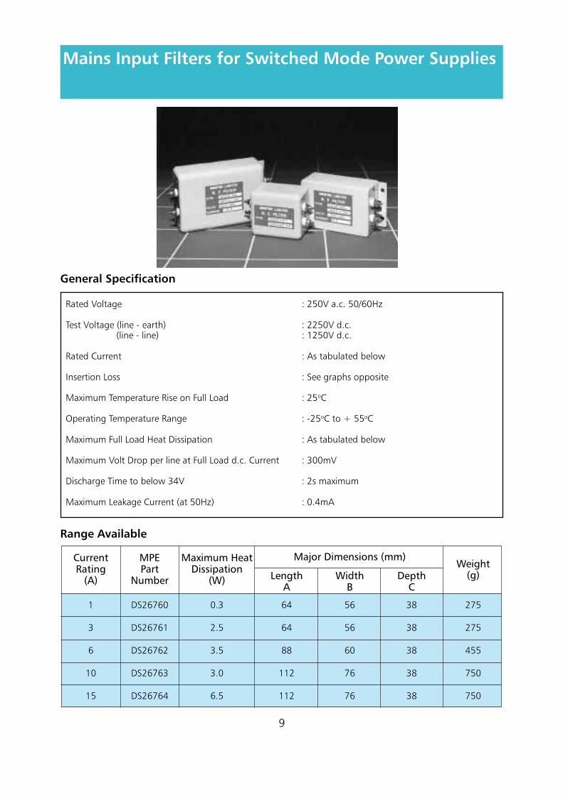
Rated Voltage : 250V a.c. 50/60Hz
Test Voltage (line - earth) : 2250V d.c. (line - line) : 1250V d.c.
Rated Current : As tabulated below
Insertion Loss : See graphs opposite
Maximum Temperature Rise on Full Load : 25oC
Operating Temperature Range : -25oC to + 55oC
Maximum Full Load Heat Dissipation : As tabulated below
Maximum Volt Drop per line at Full Load d.c. Current : 300mV
Discharge Time to below 34V : 2s maximum
Maximum Leakage Current (at 50Hz) : 0.4mA
General Specification
1
3
6
10
15
DS26760
DS26761
DS26762
DS26763
DS26764
0.3
2.5
3.5
3.0
6.5
64
64
88
112
112
56
56
60
76
76
38
38
38
38
38
275
275
455
750
750
CurrentRating
(A)
MPEPart
Number
Maximum HeatDissipation
(W) LengthA
WidthB
Major Dimensions (mm)
DepthC
Weight(g)
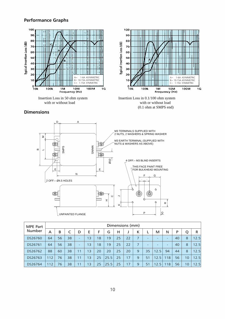
Performance Graphs
Insertion Loss in 50 ohm system Insertion Loss in 0.1/100 ohm system with or without load with or without load
(0.1 ohm at SMPS end)Dimensions
10
D A
B LM
E
N
E
Ø10
F G
R
QP
JK
H
C
M3 TERMINALS SUPPLIED WITH2 NUTS, 2 WASHERS & SPRING WASHER
M3 EARTH TERMINAL (SUPPLIED WITHNUTS & WASHERS AS ABOVE)
4 OFF:– M3 BLIND INSERTS
THIS FACE PAINT FREEFOR BULKHEAD MOUNTING
UNPAINTED FLANGE
2 OFF:– Ø4.5 HOLES
SM
PS
MA
INS
DS26760
DS26761
DS26762
DS26763
DS26764
64
64
88
112
112
MPE PartNumber A
56
56
60
76
76
B
38
38
38
38
38
C
-
-
11
11
11
D
13
13
13
13
13
E
18
18
20
25
25
F
19
19
20
25.5
25.5
G
25
25
25
25
25
H
22
22
20
17
17
J
7
7
9
9
9
K
-
-
35
51
51
L
-
-
12.5
12.5
12.5
M
-
-
94
118
118
N
40
40
44
56
56
P
8
8
8
10
10
Q
12.5
12.5
12.5
12.5
12.5
R
Dimensions (mm)
A= 1-6A ASYMMETRICB= 10-15A ASYMMETRICC= 1-15A SYMMETRIC
A= 1-6A ASYMMETRICB= 10-15A ASYMMETRICC= 1-15A SYMMETRIC
Installation Details
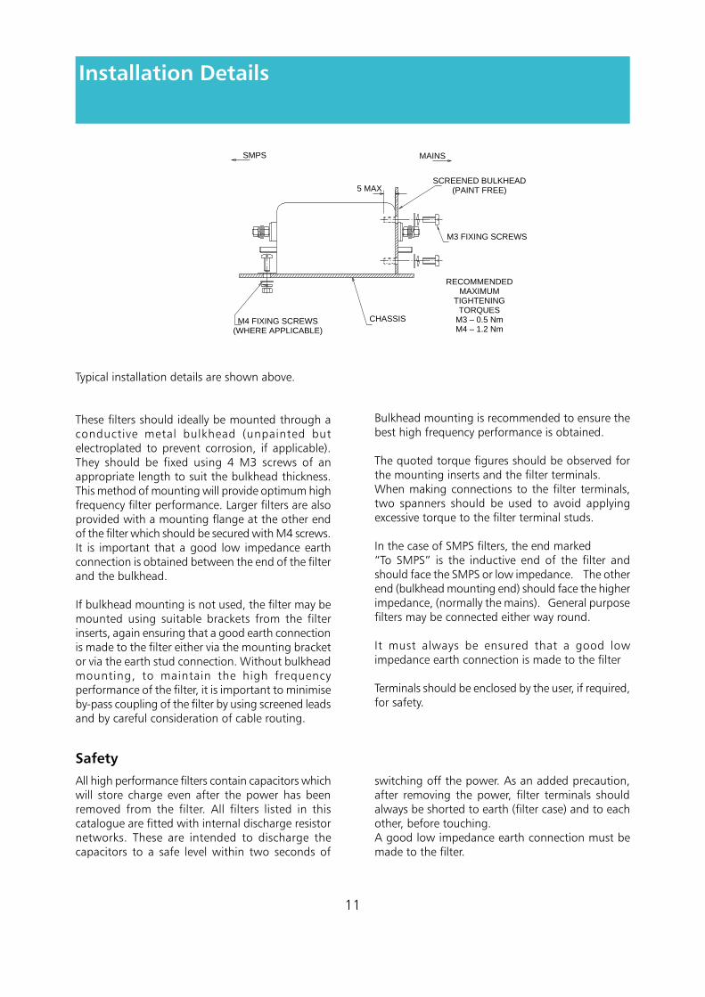
Bulkhead mounting is recommended to ensure thebest high frequency performance is obtained.
The quoted torque figures should be observed forthe mounting inserts and the filter terminals.When making connections to the filter terminals,two spanners should be used to avoid applyingexcessive torque to the filter terminal studs.
In the case of SMPS filters, the end marked“To SMPS” is the inductive end of the filter andshould face the SMPS or low impedance. The otherend (bulkhead mounting end) should face the higherimpedance, (normally the mains). General purposefilters may be connected either way round.
It must always be ensured that a good lowimpedance earth connection is made to the filter
Terminals should be enclosed by the user, if required,for safety.
All high performance filters contain capacitors whichwill store charge even after the power has beenremoved from the filter. All filters listed in thiscatalogue are fitted with internal discharge resistornetworks. These are intended to discharge thecapacitors to a safe level within two seconds of
switching off the power. As an added precaution,after removing the power, filter terminals shouldalways be shorted to earth (filter case) and to eachother, before touching.A good low impedance earth connection must bemade to the filter.
Typical installation details are shown above.
These filters should ideally be mounted through aconductive metal bulkhead (unpainted butelectroplated to prevent corrosion, if applicable).They should be fixed using 4 M3 screws of anappropriate length to suit the bulkhead thickness.This method of mounting will provide optimum highfrequency filter performance. Larger filters are alsoprovided with a mounting flange at the other endof the filter which should be secured with M4 screws.It is important that a good low impedance earthconnection is obtained between the end of the filterand the bulkhead.
If bulkhead mounting is not used, the filter may bemounted using suitable brackets from the filterinserts, again ensuring that a good earth connectionis made to the filter either via the mounting bracketor via the earth stud connection. Without bulkheadmounting, to maintain the high frequencyperformance of the filter, it is important to minimiseby-pass coupling of the filter by using screened leadsand by careful consideration of cable routing.
11
Safety
SMPS MAINS
SCREENED BULKHEAD(PAINT FREE)
M3 FIXING SCREWS
RECOMMENDEDMAXIMUM
TIGHTENINGTORQUES
M3 – 0.5 NmM4 – 1.2 Nm
CHASSISM4 FIXING SCREWS(WHERE APPLICABLE)
5 MAX
Because every application is different, standardproducts can never be ideal for every application.
By utilising standard enclosures, terminals andcomponents, we can offer a very cost-effectivecustom design service. This may involve a tailoredelectrical circuit and/or mechanical package toprovide an optimum solution to a specific filteringproblem.
If it is possible to provide details of source and loadimpedance, mode of interference, problemfrequency range, equipment noise, specificationrequirement, and details of equipment circuitry, wecan advise the most suitable filter design.
We can employ computer simulation and circuitanalysis techniques to accurately predict the actualperformance a given filter will provide in specificpractical circuits.
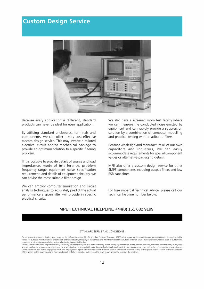
We also have a screened room test facility wherewe can measure the conducted noise emitted byequipment and can rapidly provide a suppressionsolution by a combination of computer modellingand practical testing with breadboard filters.
Because we design and manufacture all of our owncapacitors and inductors, we can easilyaccommodate requirements for special componentvalues or alternative packaging details.
MPE also offer a custom design service for otherSMPS components including output filters and lowESR capacitors.
For free impartial technical advice, please call ourtechnical helpline number below:
12
Custom Design Service
STANDARD TERMS AND CONDITIONS
Except where the buyer is dealing as a consumer (as defined in section 12 of the Unfair Contract Terms Act 1977) all other warranties, conditions or terms relating to the quality and/orfitness for purpose, merchantability or condition of the goods and/or supply of the services and whether implied by statute or common law or made expressly whether by us or our servantsor agents or otherwise are excluded to the fullest extent permitted by law.Except in relation to death or personal injury caused by our negligence, we shall not be liable by reason of any representation or any implied warranty, condition or other term, or any dutyat common law, or under any express terms, for any indirect or consequential loss or damage (including loss of profits), costs, expenses or other claims for consequential loss whatsoever(and whether caused by the negligence by us, our employees or agents or otherwise) which arise out of or in connection with the supply of the goods and/or services or the use or resaleof the goods by the buyer or arising from any breach or failure, direct or indirect, on the buyer’s part under the terms of the contract.
MPE TECHNICAL HELPLINE +44(0) 151 632 9199
Related Documents