High Penetration PV Initiative: Visualization of High Penetration PV 2013 Consultant Report Dora Nakafuji Hawaiian Electric Company GAF 0448-14 ®

Welcome message from author
This document is posted to help you gain knowledge. Please leave a comment to let me know what you think about it! Share it to your friends and learn new things together.
Transcript

High Penetration PV Initiative:Visualization of High Penetration PV
2013
Consultant Report
Dora Nakafuji
Hawaiian Electric Company
GAF 0448-14
®

HIP‐PV Task 4: Visualization of High Penetration PV
Final Report
Elaine Sison‐Lebrilla (SMUD) Dora Yen Nakafuji (HECO)
Project Leads
July 2013
Contributing Authors
Hawaiian Electric Company: Dora Nakafuji, Thomas Aukai, Lauren Gouveia, Amra Brightbill, Talin Sokugawa
Contributing Organizations
Alstom – Louis Signouretty AWS Truepower – John Zack, Jeff Friedman
Referentia System, Inc. – Matthew Shawver, Iris Koga Siemens – Ken Geisler, Harald Ilg
Disclaimers
This work is funded under the California Public Utilities Commission’s California Solar Initiative (CSI RD&D) under subcontract arrangement and partnership with the Sacramento Municipal Utility District (“High Penetration PV Initiative”). No grid data or business sensitive information is released under this work and all information pertaining to the utilities and proprietary software remain the possession of the utilities.

2
Acknowledgements
We would like to thank the California PUC CSI program and the ITRON program managers for the funding support and guidance on this project to develop advance visualization capabilities in support of renewable integration efforts. We greatly appreciate the leadership and utility partnership with the Sacramento Municipal Utility District with special recognition extended to Elaine Sison‐Lebrilla (SMUD), Stephan Barsun (ITRON) and Ann Peterson (ITRON).
3
TableofContents1.0 Introduction ...................................................................................................................................... 4
2.0 Task Description ................................................................................................................................ 6
3.0 Approach in Developing Visualization Capabilities for Operations .................................................. 7
4.0 Results of New Visualization Tools ................................................................................................. 12
4.1 Renewable Data Architecture and Analytics .............................................................................. 12
4.2 Locational Value Maps ................................................................................................................ 15
4.3 Renewable Watch ....................................................................................................................... 20
4.4 Operations Integration ................................................................................................................ 24
5.0 Status & Lessons Learned ............................................................................................................... 28
5.1 Renewable Data Architecture and Analytics – Status and Lessons Learned .............................. 28
5.2 Locational Value Maps ‐ Status and Lessons Learned ................................................................ 32
5.3 Renewable Watch ‐ Status and Lessons Learned ........................................................................ 35
5.4 Operations Integration ‐ Status and Lessons Learned ................................................................ 35
6.0 Summary ......................................................................................................................................... 40
7.0 References ...................................................................................................................................... 43

4
1.0 Introduction
Over the past 4 years, utilities such as Hawaiian Electric Companies in Hawaii and the Sacramento Municipal Utility District (SMUD) in California have experienced exponential growth in the number of customer‐sited, distributed PV generation along with increasing utility‐scale renewable generation resources. SMUD is the nation’s sixth‐largest electric utility that’s owned by its customers and serves a population of 1.4 million people in the Sacramento region in California (Figure 1.1) [1]. SMUD is a recognized industry leader in renewables and clean energy options and as a good neighbor – to their customers and to the surrounding environment. The family of Hawaiian Electric Companies (HECO Companies) comprised of the Hawaiian Electric Company (HECO), Maui Electric Company (MECO), and Hawaii Electric Light Company (HELCO), provides electric services to 95% of the state’s 1.2 million residents on the islands of Oahu, Hawaii Island, Maui, Lanai and Molokai (Figure 1.2) [2]. The Company is pursuing the use of more renewable energy alternatives to help ensure a sustainable future for the islands, with the mission to provide secure, clean energy for Hawaii.
Figure 1.1. SMUD service territory (left inset) and recent solar capacity trends (lower right).
Figure 1.2. Hawaiian Electric Companies service territory (left) and recent solar trends through
2012 on the Big Island of Hawaii (right).

5
Individually, the distributed PV systems are small and add considerable value to the customer. However, in aggregate, the behind‐the‐meter, roof‐top installations are becoming as large as some of the utilities’ generators which provide additional grid support and reliability services for the rest of the system. Although distribution circuits are typically capable of withstanding load changes over a range of conditions, the lack of visibility, accurate modeling and information to monitor and control increasing levels of variable, distributed generating resources (DG), such as photovoltaic systems (PV), on the distribution circuits have created increasing reliability and power quality concerns among utility planners and grid managers. Utilities are essentially “blind” to these behind‐the‐meter resources and need new data and analytical capabilities and tools to help capture and better understand distribution level impacts, particularly when it comes to demand side resources providing generation onto the grid. [3] Distribution Interconnection standards in Hawaii (Rule 14H [4]) and California (Rule 21 [5]) reference a 15% penetration of PV as an initial screen for high DG penetration on distribution circuits. However, both the Hawaiian Electric Companies and SMUD are contending with circuits well above 15% of DG generation to circuit maximum load. In Hawaii on the island of Oahu, a handful of feeders are above 100% of circuit maximum. At these penetration levels, traditional “rules of thumb” for design of protection and distribution systems are reaching their limits or are being compromised but not necessarily monitored by utilities. Additionally, existing load management schemes, including protective load switching on lines and under frequency load shed (UFLS) and outage management schemes designed and implemented prior to the high levels of distributed PV, may no longer be adequate. As PV generation continues to grow on distribution circuits, such grid management and operational schemes as well as the traditional modeling tools will need to be modified to account for DG generation and changing day time circuit conditions [6, 7]. As part of the HiP‐PV Initiative Task 4 Visualization effort, Hawaiian Electric Companies have initiated a number of high resolution data monitoring and evaluation efforts on the islands to gain visibility and re‐tool planning and inform new operating processes so the existing operational practices can account for high levels of DG penetration. Efforts focused on the development of the following four new visualization capabilities:
Renewable Data Architecture and Analytics – Common Data Interface Tool
Location Value Map and Online LVM
Renewable Watch
Operations Integration This work complements efforts being pursued in other Tasks as part of the HiP‐PV initiative including modeling, monitoring and technical outreach. Working with a team of industry partners including Siemens, Alstom, AWS Truepower, DNV Kema, Referentia Systems Inc. and various field monitoring equipment and telecom providers, the new visualization and analytical tools in Task 4 are being developed, piloted and utilized to help Hawaii manage increasing levels of variable renewable resources on the island grids. Results and findings have applicability to mainland grids where distributed generation penetration levels are now
6
beginning to exceed 15% and are projected to grow. Results of this collaborative effort are also expected to have impact internationally as industry partners help to propagate and share results and findings with their customer base. The final report documents the pilot deployment of high‐penetration PV utility visualization and integration tools and their design and developments conducted under Task 4 Visualization efforts as part of the SMUD/HECO HiP‐PV Initiative. Task objectives and approach are provided in Sections 2 and 3. Visualization tools, design considerations, issues/challenges, deployment experiences (good and bad), evolution based on feedback and lessons learned are captured in Sections 4 and build on the interim reports (Deliverable 1 and Deliverable 3) provided under Task 4. Benefits gained and ongoing implement efforts are also highlighted in Section 5.
2.0 TaskDescription As part of the High Penetration PV Initiative (HiP‐PV), Hawaiian Electric Companies in partnership with the Sacramento Municipal Utility District (SMUD) initiated a number of high resolution data monitoring and evaluation efforts on the islands to gain visibility and inform new operating practices to account for impacts of high penetrations of distributed generation (DG) [8]. Task 4 Visualization efforts focused on developing and piloting new visualization and analytical tools to help planners and operators visually track and trend distributed generation systems (i.e., rooftop PV systems) and their impacts on the grid [9]. Subtasks for Task 4 include 4.1 Assessing System Needs and Strategies
‐ Convene meetings with System Operations staff and capture existing needs ‐ Identify visual mitigation strategies to bring awareness of system impacts from
distributed PV ‐ Identify important operational strategies that can benefit from monitoring and control
of distribution feeder parameters ‐ Develop and pilot analytical tools to allow evaluation of high penetration PV data to
inform modeling scenarios 4.2 Develop, Pilot and Validate Visualization Tools
‐ Compile database of solar resources on the distribution system capable of handling high‐frequency 1 sec data to 15 min resolution.
‐ Utilize Locational Value Maps (LVM) to identify and track highly impacted distribution circuits and develop automated capability to update and visually track penetration levels
‐ Develop an operational tool that incorporates field monitoring data, planning data along with live system data to improve awareness of renewable resource availability
‐ Begin preliminary efforts with EMS vendors to enhance data analysis and use high‐resolution solar resource information in the operational environment
‐ Capture lessons learned through piloting efforts
7
3.0 ApproachinDevelopingVisualizationCapabilitiesforOperations
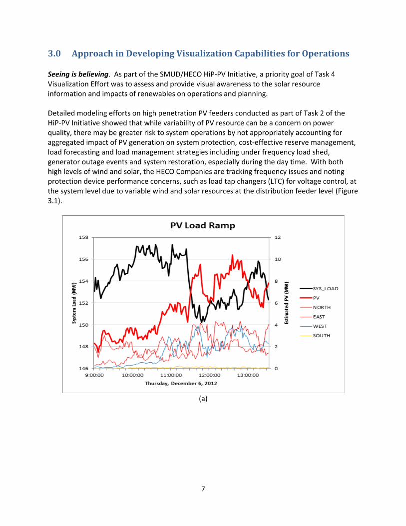
Seeing is believing. As part of the SMUD/HECO HiP‐PV Initiative, a priority goal of Task 4 Visualization Effort was to assess and provide visual awareness to the solar resource information and impacts of renewables on operations and planning. Detailed modeling efforts on high penetration PV feeders conducted as part of Task 2 of the HiP‐PV Initiative showed that while variability of PV resource can be a concern on power quality, there may be greater risk to system operations by not appropriately accounting for aggregated impact of PV generation on system protection, cost‐effective reserve management, load forecasting and load management strategies including under frequency load shed, generator outage events and system restoration, especially during the day time. With both high levels of wind and solar, the HECO Companies are tracking frequency issues and noting protection device performance concerns, such as load tap changers (LTC) for voltage control, at the system level due to variable wind and solar resources at the distribution feeder level (Figure 3.1).
(a)

8
(b)
Figure 3.1 a) System uncontrolled ramp concerns due to solar (source: HELCO) and b) observed increase in local feeder LTC movement due to solar (source: HECO).
Get data fast became the next priority goal. Like most utilities, communication and secure protocol to backhaul the data is limited at the distribution level in Hawaii. This required innovative solutions that leveraged existing communication infrastructure including the use of a wide range of protocol for microwave, radio and cellular devices. Working with utility field and instrumentation crews, SCADA‐enable solar irradiance sensors and cellular devices to support non‐SCADA communication were deployed. Figure 3.2 and Figure 3.3 showcase a variety of solar and wind monitoring devices deployed across Hawaiian Electric Companies’ and SMUD service territories at substations and strategic monitoring locations.
Figure 3.2. Examples of various solar monitoring devices deployed in Hawaii and California.

9
Figure 3.3. Remote wind monitoring sensors (SODAR and LIDAR) and temperature profilers (radiometer) deployed in Hawaii as part of the forecasting network (WindNET). In Hawaii, to facilitate documentation of different device setups, acronym identifiers were created. For example, reference irradiance sensors that served to join data to transmission infrastructure were identified as TJD. A short description for each sensor is provided below.
TJD sensors serve as “reference sensors”. TJD sensors consisting of calibrated Lycor 100 irradiance sensors were installed in two configurations, either as a tri‐pod stand which left communication antenna, GPS and data acquisition (DAQ) devices exposed or used a plastic bin to house antenna, GPS and DAQ at substations more susceptible to vandalism. Complete sensor kits were purchased from Campbell Scientific. TJD devices were sited at utility sites and non‐utility sites in consideration of forecasting and grid monitoring needs.
Locational monitors versions 1 and 2 (LM‐1 and LM‐2) were deployed at various substations during the project period. Both consisted of using a small PV sensor (0‐10V) to telemetered voltage output data from the small panel back to the utility SCADA system. LM‐1 devices were developed internally by the utility and did not have external calibration. They required a reference source such as a nearby TJD for correlation. LM‐2 devices are commercially available, calibrated sensors with both voltage and temperature sensing capability. These devices are distributed by IMT Solar (www.imtsolar.com). Plans are to replace LM‐1 with LM‐2 as they are easier to install, have digital connection to SCADA via a RS485 connector and are commercially calibrated.
SMS are calibrated shadowband sensor for determining components of the total irradiance (direct normal irradiance (DNI) and diffuse). These stations are Campbell Scientific kits installed by AWS Truepower to support solar forecasting needs. They serve similar purposes as TJD which measures total irradiance. They are part of the SolarNET sensor network for solar forecasting in Hawaii.

10
SODAR sensors are sonic detection and ranging devices that remotely measure wind speed and direction using sound. SODAR systems were either mobile, PV powered systems or station powered and are also part of the WindNET and SolarNET for forecasting and cloud modeling in Hawaii. Atmospheric Research and Technology (ART) SODARs (www.sodar.com) and deployment services were used in Hawaii. ART VT‐1 SODARs were also used in the California SODAR campaign conducted from 2002 to 2004 by the California Energy Commission. They provide multi‐level measurements from ground level up to 300m. To minimize noise levels near the areas of deployment, measurements in Hawaii ranged from ground level up to 200m.
LIDAR sensors use light to measure wind speed and direction and provide the capability to scan an area ahead of the wind facilities. The Leosphere WindCube 100S (www.leosphere.com) was deployed by Leopshere, AWS Truepower and Hawaiian Electric staff on Oahu. The LIDAR is part of the WindNET supporting forecasting.
Radiometers are remote sensors used to vertical temperature from the ground up to 1km. A Radiometrics unit was deployed by AWS Truepower for about 9 months on the Big Island and moved to Maui to continue vertical temperature measurements. Data provides a more accurate temperature profile to initiate meso‐scale models for forecasting wind for the islands. These devices are part of the WindNet and SolarNet.
PMI units are commercial power quality monitors manufactured by Revolution (www.powermonitors.com). They were installed by the utility at various customers who were willing to participate and share feeder level power quality data in support of feeder monitoring and distribution model validation. Data was used by DNV to validated modeling studies and develop high penetration modeling methodologies as part of Task 2 of this project.
Monitoring sites for various devices were chosen resulting from a combination of factors including proximity to load, unique terrain, microclimate, shading and other structural blockage and diversity of load types on the circuit. Each site also had unique deployment challenges including limited communication options, threat of vandalism, safety clearance requirements and customer access constraints. Table 3.1 summarizes various means used to access and backhaul data. As both SMUD and HECO Companies began deploying sensors, the management of high resolution data and large volumes of data quickly became an issue.
Table 3.1. List of monitoring devices, communication and data resolution
Field Device Communication Access Data Resolution
TJD Solar Kits – Irradiance (W/m2) Non‐SCADA, Cellular 1 min
LM 1 – % availability (%), calibration reference needed
SCADA 2 sec
LM 2 – Voltage to calibrated Irradiance (W/m2)
SCADA 2 sec
SMS Stations Irradiance (W/m2) components
Non‐SCADA, Cellular 1 min

11
Wind mast (m/s) Temperature (deg C) Pressure (Pa)
PMI – power quality (V, Amp, Load) Non‐SCADA, Manual data pulls
Various (1 ‐ 15 min)
SODAR – volumetric wind data (m/s, direction)
Non‐SCADA, Cellular Various (5 min – 15 min)
Radiometer – Temperature (deg C) Non‐SCADA, Cellular 1 min
LIDAR – wind data (m/s) Non‐SCADA, Cellular Various
Information to action was the third driving goal. Once data was received, questions arose on how best to combine and mine the data and what utility tools were available to do so. Existing utility analytical tools tended to be software and vendor product specific with data analysis software specific to the device or database. Data also was stored on multiple databases, formats and required separate logins, database programming expertise or other department staff with local database access to download and transfer the information. Hunting down and assembling data to perform analytics was a time consuming task often taking several days to weeks before analysis could even begin. With higher resolution, diverse formats, larger volumes of data and the future need for real‐time streaming of information across SCADA and non‐SCADA platforms, the focus of Task 4 activities that followed was to enable flexible and secure access to information on a common platform and to flexibly render large volumes of data in a graphical and visual way. To enable a common platform and visualization capabilities, the Hawaiian Electric staff initiated a number of pilot initiatives leveraging various funding sources and developed new partnerships with industry to build capability and new data architectures to support the processing and secure handling of high volumes of distributed data. Table 3.2 summarizes the new visualization capabilities, their purpose, desired benefits and utility‐industry partnerships.
Table 3.2. Targeted Visualization Capabilities in Task 4.
Visualization Capability
Design Concept Partnerships
Renewable Data Architecture and Analytics – Common Data Interface Tool
Develop a common platform data management capability using TREX and Perspective interface with enhanced time series and large data handling capabilities Benefits: Enhance analytical capability and efficiency
Referentia Systems Inc. and HECO Companies; Funded in partnership with HREDV
Locational Value Map (LVM) and Online LVM
Visually track and trend growth of PV by location and standardize a process for determining feeder penetration levels
HECO Companies (internal ITS, GIS Mapping, Renewable Planning, Resource

12
Benefits: Enable capability to track distributed PV resources and future impact
Acquisitions, Corp Com departments)
Renewable Watch
Enable a way to “see” the value of renewable resources (including behind the meter PV generation) during various times of the day Benefits: Operations and planning able to account for behind‐the‐meter generation; increase workforce understanding of solar resource and magnitude of DG resources on the grid; and support customer of high penetration concerns and contributions on the grid
HECO Companies (Internal ITS, Renewable Planning and Corporate Communications)
Operations Integration
Enhance System Operations tools by integrating DG generation and probabilistic wind and solar forecasts Benefits: Improve operational awareness of DG and variable renewable resources with new capability to manage, forecast and anticipate
EMS vendors –Siemens and Alstom; Forecast provider – AWS Truepower; DG aggregator – DNV; HECO Companies
4.0 ResultsofNewVisualizationTools
Visualization capabilities and analytics are a major component of integrating renewables onto the grid. While considerable efforts have been expended on creating new data sources and forecasting capabilities, very little effort has been spent to assist utilities in operationalizing such capabilities and integrating into processes and procedures. Overcoming adoption barriers also requires user acceptance. As such, Task 4 Visualization efforts focused on technology integration, enabling analytics to efficiently manage high levels of variable renewable resources and building user confidence and understanding in order to better utilize the new probabilistic tools and real‐time information. This section includes details on the development of the visualization capabilities, lessons learned and progress toward adoption.
4.1 RenewableDataArchitectureandAnalytics Managing and analyzing system and distribution level data and the new field monitoring devices required consolidation and secure access of data from a variety of databases across the Companies. Data access included the Companies’ customer information system (CIS), energy management system (EMS), geographic information system (GIS), SCADA enabled power quality devices and solar irradiance and other non‐SCADA field monitoring devices for wind and solar. Leveraging additional development funding from the Hawaii Renewable Energy

13
Development Venture (HREDV) [10], the Companies partnered with Referentia Systems, Inc. to develop and deploy a new Time Series Rapid Exploration (TREX) database and Perspective interface for handling SCADA and non‐SCADA data for real‐time analysis and planning. This rapid data management and analysis capability offered by Referentia’s TREX product bridges a critical gap in current utility analysis capabilities by providing a common database platform to quickly access and handle the “big data” (large volumes of data and data sources). A rapid data interface and analysis capability will support Hawaii and California utilities including IOUs manage the “big data” to operate future micro‐systems and smarter grid infrastructures. Factors that went into the development of the TREX capability are summarized in Table 4.1. Functional capabilities of the TREX database are compared with traditional utility Historians and existing relational database structures. As noted in the 2006 California ISO study “California RPS Integration Cost Analysis: Multi‐Year Analysis Results and Recommendations”, the authors were using an OSISoft PI System historian as the main data source. They reported “The majority of time and effort required for the multi‐year analysis was dedicated to data collection and processing.” Difficulties included the speed with which data could be retrieved from the historian, challenges in matching time stamps of disparate sources not from SCADA, problems finding data due to the lack of fast data search capability, and historian lossy data compression resulting in inaccurate aggregated values. Without TREX, considerable manual efforts would have been required to identify datasets of interest and match with non‐SCADA data series from field sensors. As shown in Figure 4.1, the TREX technology is envisioned to serve as a common database platform to manage, access and conduct rapid analysis of both SCADA and non‐SCADA data.
Table 4.1. Design Considerations for a New Data Architecture and Analytics Capability.
Need Requirement Relational Historian T-REX
• Build aggregates and derived parameters
• Simulation-based forecasts
• High throughput historical R/W• Delete and rewrite data• Integrate with numerical computing
toolsSlow No Yes
• Operational situational awareness
Near-realtime data viewsNo Yes Yes
• Exchange data across network segments
One-way replication3rd party, slow built-in
• Not always system of record, many disparate sources
Bulk load non-real-time, offline data
Slow No Yes
• Large volumes of data
• Lossless compression• High throughput read/write
Expands Data
Lossy Lossless
• Data sets are non-contiguous, many non-expert users
• Help users find data of interest• Interactive, easy to use UI
No No Yes

14
Figure 4.1. Architecture for data management and exchange using T‐REX.
Figure 4.2. Perspective view of renewable data and customizable data‐handling features (A‐D).
15
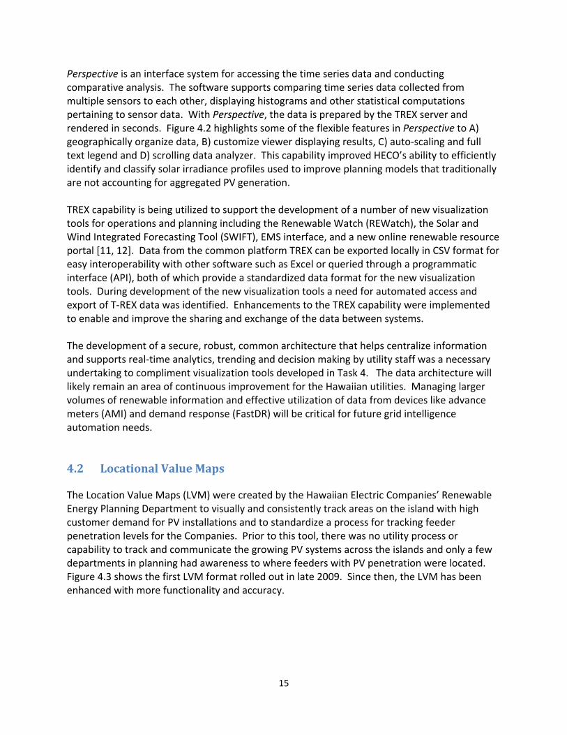
Perspective is an interface system for accessing the time series data and conducting comparative analysis. The software supports comparing time series data collected from multiple sensors to each other, displaying histograms and other statistical computations pertaining to sensor data. With Perspective, the data is prepared by the TREX server and rendered in seconds. Figure 4.2 highlights some of the flexible features in Perspective to A) geographically organize data, B) customize viewer displaying results, C) auto‐scaling and full text legend and D) scrolling data analyzer. This capability improved HECO’s ability to efficiently identify and classify solar irradiance profiles used to improve planning models that traditionally are not accounting for aggregated PV generation. TREX capability is being utilized to support the development of a number of new visualization tools for operations and planning including the Renewable Watch (REWatch), the Solar and Wind Integrated Forecasting Tool (SWIFT), EMS interface, and a new online renewable resource portal [11, 12]. Data from the common platform TREX can be exported locally in CSV format for easy interoperability with other software such as Excel or queried through a programmatic interface (API), both of which provide a standardized data format for the new visualization tools. During development of the new visualization tools a need for automated access and export of T‐REX data was identified. Enhancements to the TREX capability were implemented to enable and improve the sharing and exchange of the data between systems. The development of a secure, robust, common architecture that helps centralize information and supports real‐time analytics, trending and decision making by utility staff was a necessary undertaking to compliment visualization tools developed in Task 4. The data architecture will likely remain an area of continuous improvement for the Hawaiian utilities. Managing larger volumes of renewable information and effective utilization of data from devices like advance meters (AMI) and demand response (FastDR) will be critical for future grid intelligence automation needs.
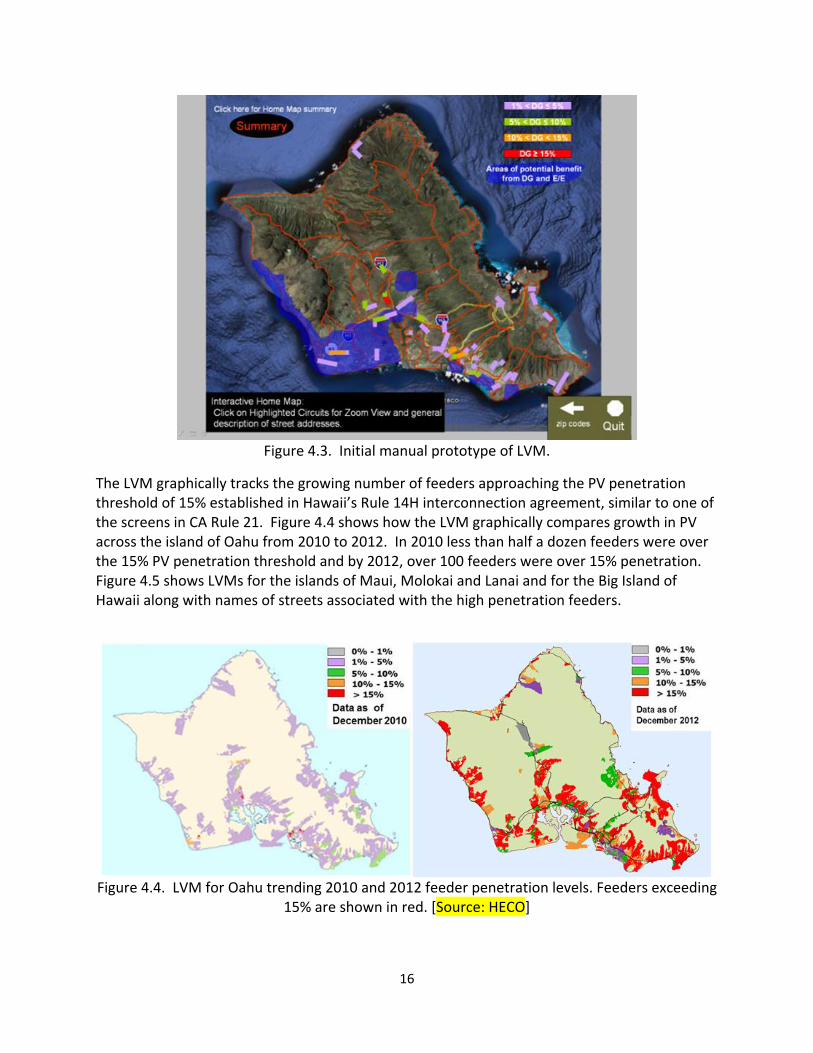
4.2 LocationalValueMaps The Location Value Maps (LVM) were created by the Hawaiian Electric Companies’ Renewable Energy Planning Department to visually and consistently track areas on the island with high customer demand for PV installations and to standardize a process for tracking feeder penetration levels for the Companies. Prior to this tool, there was no utility process or capability to track and communicate the growing PV systems across the islands and only a few departments in planning had awareness to where feeders with PV penetration were located. Figure 4.3 shows the first LVM format rolled out in late 2009. Since then, the LVM has been enhanced with more functionality and accuracy.
16
Figure 4.3. Initial manual prototype of LVM.
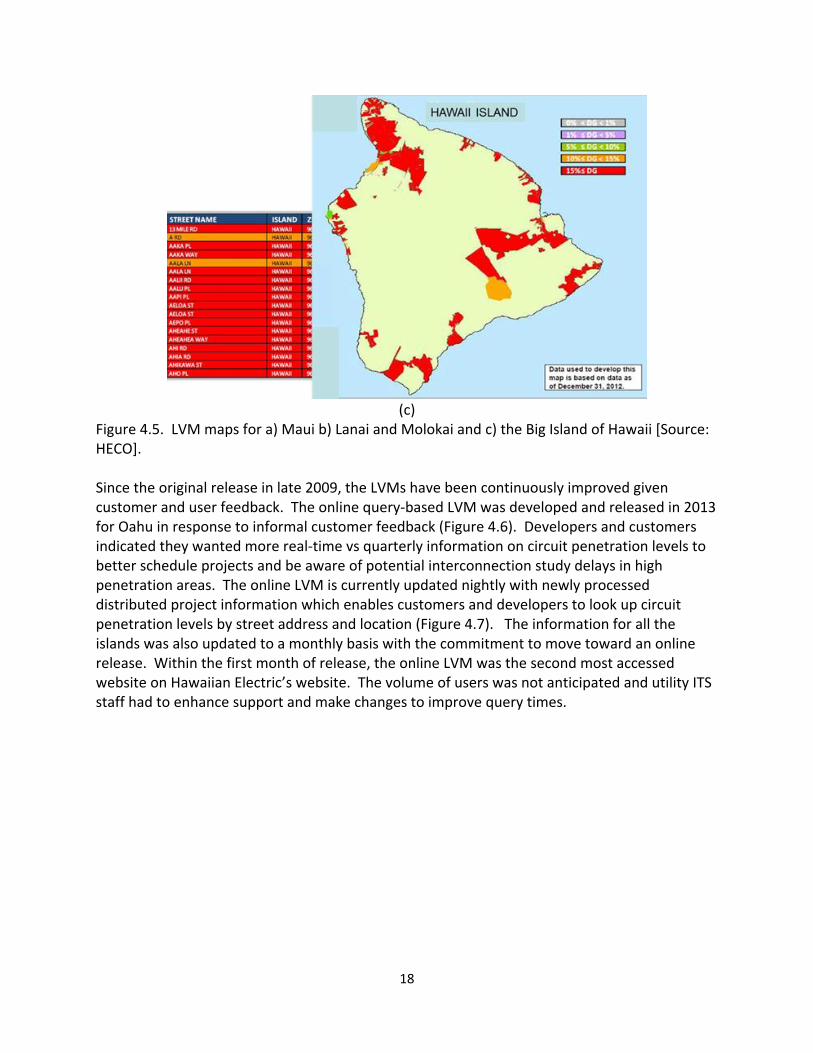
The LVM graphically tracks the growing number of feeders approaching the PV penetration threshold of 15% established in Hawaii’s Rule 14H interconnection agreement, similar to one of the screens in CA Rule 21. Figure 4.4 shows how the LVM graphically compares growth in PV across the island of Oahu from 2010 to 2012. In 2010 less than half a dozen feeders were over the 15% PV penetration threshold and by 2012, over 100 feeders were over 15% penetration. Figure 4.5 shows LVMs for the islands of Maui, Molokai and Lanai and for the Big Island of Hawaii along with names of streets associated with the high penetration feeders.
Figure 4.4. LVM for Oahu trending 2010 and 2012 feeder penetration levels. Feeders exceeding 15% are shown in red. [Source: HECO]

17
(a)
(b)
18
(c)
Figure 4.5. LVM maps for a) Maui b) Lanai and Molokai and c) the Big Island of Hawaii [Source: HECO]. Since the original release in late 2009, the LVMs have been continuously improved given customer and user feedback. The online query‐based LVM was developed and released in 2013 for Oahu in response to informal customer feedback (Figure 4.6). Developers and customers indicated they wanted more real‐time vs quarterly information on circuit penetration levels to better schedule projects and be aware of potential interconnection study delays in high penetration areas. The online LVM is currently updated nightly with newly processed distributed project information which enables customers and developers to look up circuit penetration levels by street address and location (Figure 4.7). The information for all the islands was also updated to a monthly basis with the commitment to move toward an online release. Within the first month of release, the online LVM was the second most accessed website on Hawaiian Electric’s website. The volume of users was not anticipated and utility ITS staff had to enhance support and make changes to improve query times.

19
Figure 4.6 Online LVM front page [13]

20
Figure 4.7. Sample online address query display results. [13]
4.3 RenewableWatch The Renewable Watch was developed to provide utility staff and customers visibility to the value of renewable resources during various times of the day. One of the biggest challenges for utilities contending with high penetrations of PV, especially behind‐the‐meter, is the lack of visibility to the amount of energy being generated by local distributed systems. Many utility staff and customers are not aware of the variability impacts of PV on the grid, how rapidly conditions change with cloud cover, how much renewable generation is available and when they are generating during the course of the day. Collecting and using information from wind and solar irradiance monitoring devices and grid monitoring devices across the islands, aggregated PV forecasts and distributed generation power curves were derived for different regions across the islands. The information allowed the Renewable Energy Planning Division to estimate an aggregated behind‐the‐meter DG generation contribution from PV by substations. Figure 4.8 shows a chart trending system net load (red) and gross load (blue) for a week in October. Net load is defined as the load served by the utility and the gross load is the total demand on the system or the apparent load. The difference between the two is an estimate for the aggregated distributed generation provided by local PV generation. Feedback gained from operations and planning personnel indicated

21
that this was the first time they had seen the magnitude of the impact of roof‐top PV on system load and the information is helping to keep an eye on the decrease in mid‐day load.
Figure 4.8. System load curves showing Gross Load (Load + PV) and Net Load (load served by the utility). Following deployment of the initial Renewable Watch screens, feedback has been positive. Content is now being requested to be displayed in Operations, Power Plants and the Company’s intranet and eventually on the Company’s internet for public use. Content is also now being developed for sister utilities for the islands of Maui, Molokai, Lanai and Hawaii. The Renewable Watch screens provided a means to capture the value of behind‐the‐meter PV generation from across the island. It enabled staff to see the value of Renewables on the system in real‐time and provided an intuitive feel to the weather conditions, cloud patterns and irradiance information. Staff gained new skills designing the screens using the 4Winds package which is a widely used industry package for designing large display boards. Results from this effort continue to add new insight and stimulate discussions at common areas. The information in Figure 4.8 while interesting, was not intuitive to the general workforce. Based on discussions with utility staff from across the company from executives, customer service, load forecasting and field technicians on their awareness of PV impact and what information they would like to know, the Renewable Watch (REWatch) screens were created as a way to increase awareness of renewables. The idea was to provide utility staff a sense for the weather and solar resource, measured as irradiance (W/m2), throughout the day and the connection to PV generation and system load. The information was to also be visually intuitive
22
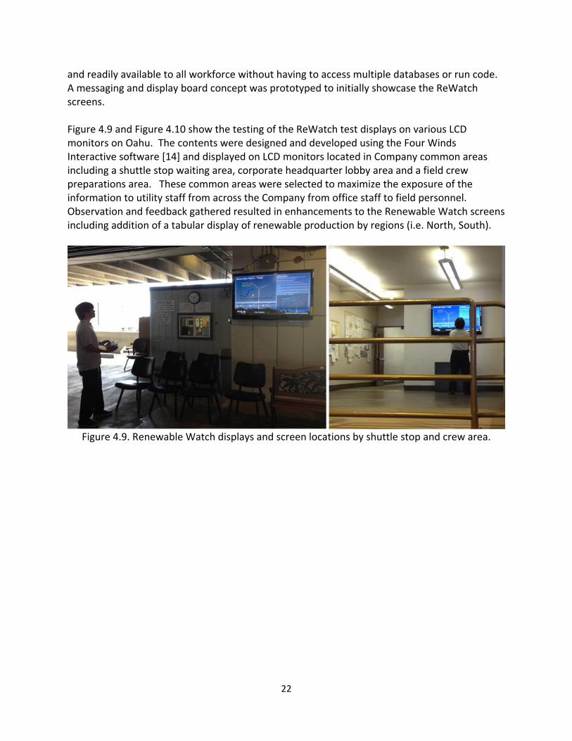
and readily available to all workforce without having to access multiple databases or run code. A messaging and display board concept was prototyped to initially showcase the ReWatch screens. Figure 4.9 and Figure 4.10 show the testing of the ReWatch test displays on various LCD monitors on Oahu. The contents were designed and developed using the Four Winds Interactive software [14] and displayed on LCD monitors located in Company common areas including a shuttle stop waiting area, corporate headquarter lobby area and a field crew preparations area. These common areas were selected to maximize the exposure of the information to utility staff from across the Company from office staff to field personnel. Observation and feedback gathered resulted in enhancements to the Renewable Watch screens including addition of a tabular display of renewable production by regions (i.e. North, South).
Figure 4.9. Renewable Watch displays and screen locations by shuttle stop and crew area.

23
Figure 4.10. Renewable Watch test display.
Figure 4.11. Renewable Watch for Oahu
Figure 4.11 shows the current Renewable Watch contents page. Featured windows include the
‘Renewable Watch – Today’ window which updates system information every 15 minutes,
‘Renewable Production’ information by aggregated regions shown in a tabular format
24
‘Renewable Watch‐Yesterday’ window showing system information for the prior day conditions in comparison to current day
Weather forecast information on the lower left
‘Information’ window with brief explanation of the data shown
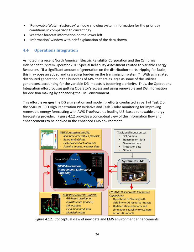
4.4 OperationsIntegration As noted in a recent North American Electric Reliability Corporation and the California Independent System Operator 2013 Special Reliability Assessment related to Variable Energy Resources, “If a significant amount of generation on the distribution starts tripping for faults, this may pose an added and cascading burden on the transmission system.” With aggregated distributed generation in the hundreds of MW that are as large as some of the utilities generators, accounting for the variable DG impacts is becoming a priority. Thus, the Operations Integration effort focuses getting Operator’s access and using renewable and DG information for decision making by enhancing the EMS environment. This effort leverages the DG aggregation and modeling efforts conducted as part of Task 2 of the SMUD/HECO High Penetration PV Initiative and Task 3 solar monitoring for improving renewable energy forecasting with AWS TruePower, a leading U.S. based renewable energy forecasting provider. Figure 4.12 provides a conceptual view of the information flow and enhancements to be derived in the enhanced EMS environment.
Figure 4.12. Conceptual view of new data and EMS environment enhancements.

25
Siemens and Alstom, two leading EMS providers, are participating in the development and prototyping initiative to gain exposure to growing DG needs and help enhance utility capability through new automation and visualizations within their respective EMS environments. This unique, dual platform approach is being pursued as the Hawaiian Electric Companies use both EMS vendors. For Operations, SMUD and Hawaiian Electric Company on Oahu utilize the Siemens EMS and MECO and HELCO utilize the Alstom EMS. As such, SMUD and Hawaiian Electric Company on Oahu will gain from the enhancements on the Siemens Spectrum Power TG product. MECO is responsible for operations on Maui, Molokai and Lanai and HELCO is responsible for grid operations on the Big Island of Hawaii. The Alstom EMS platform is being enhanced with operational insight and needs based on Operator engagements from the respective islands. New logic is being investigated and prototyped to account for DG and non‐DG resources on the grid and to incorporate real‐time probabilistic forecasts. Efforts focus on the following,
Develop and test out an aggregation approach for integrating the distributed PV installations and information for system operations
Develop and test new EMS logic to use new forecasting data streams, confidence bands and ramp statistics
Develop functional prototypes or mock‐up displays and alert capability to inform real‐time operations of changing renewable conditions
Test out CIM format to update DG field information and distribution network needs
Involve and gather operator feedback on the design, use and evaluation Efforts also require close interaction with System Operations Network and ITS support personnel to ensure development of a sustainable and cyber‐secure process for updating the DG data and accessing real‐time renewable forecasts from renewable energy forecast providers. With increasing levels of variable generation and distributed behind‐the‐meter generation, these resources cannot be ignored and will have impacts on system operation, especially during contingency events. Task summaries for both the Siemens DMAS and the Alstom RDG‐VIS are provided in Table 4.1. From a high level perspective, the goal of each of the EMS projects is to provide operators the information needed to manage the impact of DG and renewable generation on the power system. Two key activities needed to achieve this goal include:
I. Information integration is the process by which raw data is collected from several
systems belonging to multiple domains, and then being converted, aggregated and
transformed into meaningful information for the operator.
II. Visualization relates to the set of techniques used to present the information to
operator. With modern User Interfaces, users can easily select all kinds of information
they want to see without losing sight of their traditional business context.

26
Table 4.1 Summary of EMS Vendor efforts.
Siemens Distribution Management and Analysis (DMAS)
Tasks include DMAS Modifications & Enhancements The primary modifications/enhancements to the standard DTS that will be needed for this project are extension of the power system model to be used in the DMAS, a mechanism for data exchange with the production EMS, interfaces to receive forecast data for load, COP, renewable generation availability/generation, and planned equipment outages. Network Model Extension For DMAS to simulate the power system behavior its network model will have to encompass the entire 46kV network and enough of the 12.5kV network to depict the renewable generation with reasonable granularity. Leverage an aggregated nodal model of the renewable generation in some format as well as a measurement available in the EMS/SCADA that represents current renewable generation availability at those nodes (substations or feeders). EMS Data Exchange (DQSL) DMAS will need to receive current real‐time SCADA data from the EMS to initialize the simulation and will also need to return results to the EMS for presentation. The preferred method for real‐time data exchange between Spectrum Power TG systems is a connection referred to as DQS Link. Forecast Data Interfaces DMAS will need to receive the relevant operational forecast data, these will the load forecast (from Current Operating Plan) and planned equipment outages (these can be manually entered or from the Equipment Outage Scheduler). Metrics returned to EMS Each time DMAS executes a simulation run it will derive measurement values representing the network state with the predicted renewable generation. HECO and Siemens will work together to agree on the metrics to be calculated by DMAS at the end of simulation and sent to EMS. Visualization Displays Based on the metrics above HECO and Siemens will work together to define the desired visualization displays to presented. Siemens will prepare these initial displays for presentation on both DMAS and EMS. Automated Execution Initial implementation will focus on developing the simulation scenarios and tuning the DMAS model to produce the desired results. During this effort DMAS will be operated in the traditional DTS mode, i.e., by manually initiating a simulation run. To convert to
27
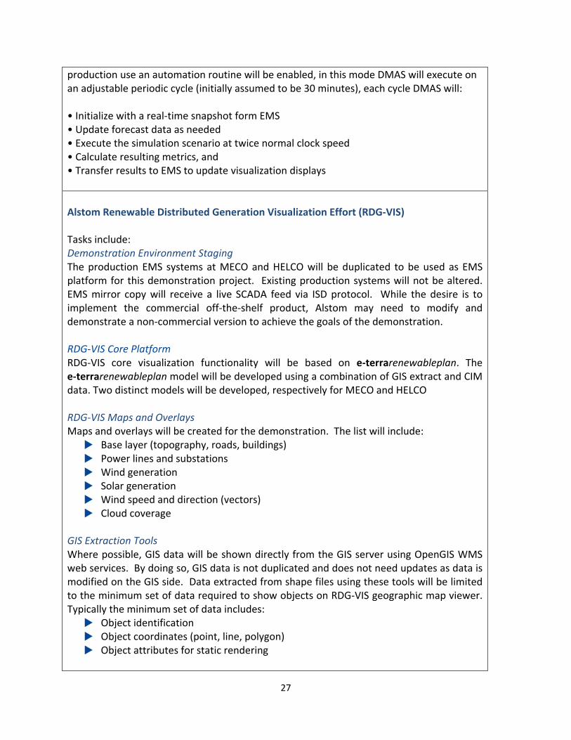
production use an automation routine will be enabled, in this mode DMAS will execute on an adjustable periodic cycle (initially assumed to be 30 minutes), each cycle DMAS will: • Initialize with a real‐time snapshot form EMS • Update forecast data as needed • Execute the simulation scenario at twice normal clock speed • Calculate resulting metrics, and • Transfer results to EMS to update visualization displays
Alstom Renewable Distributed Generation Visualization Effort (RDG‐VIS) Tasks include: Demonstration Environment Staging The production EMS systems at MECO and HELCO will be duplicated to be used as EMS platform for this demonstration project. Existing production systems will not be altered. EMS mirror copy will receive a live SCADA feed via ISD protocol. While the desire is to implement the commercial off‐the‐shelf product, Alstom may need to modify and demonstrate a non‐commercial version to achieve the goals of the demonstration. RDG‐VIS Core Platform RDG‐VIS core visualization functionality will be based on e‐terrarenewableplan. The e‐terrarenewableplan model will be developed using a combination of GIS extract and CIM data. Two distinct models will be developed, respectively for MECO and HELCO RDG‐VIS Maps and Overlays Maps and overlays will be created for the demonstration. The list will include:
Base layer (topography, roads, buildings) Power lines and substations Wind generation Solar generation Wind speed and direction (vectors) Cloud coverage
GIS Extraction Tools Where possible, GIS data will be shown directly from the GIS server using OpenGIS WMS web services. By doing so, GIS data is not duplicated and does not need updates as data is modified on the GIS side. Data extracted from shape files using these tools will be limited to the minimum set of data required to show objects on RDG‐VIS geographic map viewer. Typically the minimum set of data includes:
Object identification Object coordinates (point, line, polygon) Object attributes for static rendering

28
Distribution Model (SynerGEE) Extraction Tools DG solar cluster information, covering location, identification, capacity and node connection to the grid, will be obtained from the SynerGEE database in a CIM format. Alstom will develop an ad‐hoc converter to import this data into RDG‐VIS. Forecast Interface A web service adapter will be developed by Alstom to fetch forecast data from the AWS web portal and pass it to e‐terrarenewableplan. The communication will be point to point and will not be redundant. If communication is lost retries will be attempted until successful or aborted. Alstom will develop an adapter to import data from AWS web service interface into RDG‐VIS Supervisory Control and Data Acquisition Interface A SCADA Interface will be developed to exchange analog values with SCADA. ALARM Interface An ALARM Interface will be developed RDG‐VIS to send forecast related alarms to the EMS Alarm application.
The development effort under this project will result in the following new functionality:
Automatic acquisition of resource‐based forecast from Renewable Forecaster (AWS Truepower)
Near real time visualization of wind and solar generation current (from SCADA), past and forecasted
Geographic map overlays showing wind and solar generation, on top of the power system background
Visualization of solar DG impact aggregated at substation level Resource‐based forecast made available to EMS for network studies Ability to use resource‐based forecast as SCADA pseudo‐measurement to improve
renewable observability Forecast‐based alarms to alert operators of future major system events
5.0 Status&LessonsLearned
5.1 RenewableDataArchitectureandAnalytics–StatusandLessonsLearned
The TREX and Perspective user interface capability is currently being utilized to support the development of a number of new visualization tools for System Operations and Planning

29
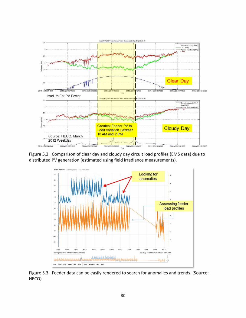
including the Renewable Watch (REWatch), the Solar and Wind Integrated Forecasting Tool (SWIFT) [15], an EMS interface and a new online renewable data portal. Using the TREX database, the Perspective user interface and commercial analysis software such as Matlab, the management of large data files, search routines and analysis of data across multiple platforms has now become a more routine process. Figure 5.1 shows the Perspective screen with the menu of data organized by island, measurement device and regions and the graphical plot of the data on the right. Sectionalizing data by geographic area helped new engineers and staff quickly get oriented on finding data and securely accessing information without multiple logins to various databases. The TREX tool and common data architecture has enabled utility planning and operation staff access to solar resource data and DG production data from across the islands. The ability to combine data as shown in Figure 5.2 from SCADA and non‐SCADA sources provides new perspective on how much the load on feeders can vary from day to day due to clouds impacting PV generation. Information sources include SCADA data of measured feeder load (green line), field measured solar irradiance (blue line) and the resulting gross feeder load (red line) estimated using irradiance and estimated PV power output. Variability conditions spanning clear day to cloudy day data on feeders can be quickly accessed and analyzed to inform transmission and distribution planning studies and IRS studies for high penetration feeders. Anomalies such as load switching on feeders, curtailments and feeder trends can also be quickly assessed when graphically displayed (Figure 5.3).
Figure 5.1. Analysis of solar data on Oahu using the Perspective interface to TREX. (Source:
HECO)
30
Figure 5.2. Comparison of clear day and cloudy day circuit load profiles (EMS data) due to distributed PV generation (estimated using field irradiance measurements).
Figure 5.3. Feeder data can be easily rendered to search for anomalies and trends. (Source: HECO)

31
For high penetration PV assessments on distribution feeders, Figure 5.4 illustrates the importance of timely review and tracking of feeder load profiles. In addition to capturing minimum load and maximum load data points for the feeder, the minimum daytime load during the period of maximum PV production (10am to approximately 2pm) is emerging as another critical data point for assessing high penetration feeders. More and more of the distribution circuit profiles are changing to something characteristics of the “Loch Ness”shape shown in Figure 5.4a where only the morning load rise and the evening load peak are noticeable load periods. The rest of the time, the load is served by the local PV or DG. In some instances, the load is negative (Figure 5.4b), indicating a condition where the local distributed generation is in excess of the demand in the local area and is backfeeding onto the system. In aggregate as more of the circuits exhibit this “Loch Ness” effect and backfeed, the more the net system load will deviate from historical profiles and will need to be monitored in a timely and routine fashion. Backfeed is an issue is of great concern to utilities as high levels of backflow can negate traditional protection on distribution feeders and reliability of the system, especially during contingencies (i.e. outages, non‐normal conditions).
(a)

32
(b)
Figure 5.4. a) Visual confirmation of mid‐day (10am to 2pm for Hawaii) impact of PV on different types of feeder loads (commercial, residential, industrial or combined) at different resolutions with different monitoring devices (SCADA and BMI power monitoring devices) and b) measured backfeed condition. (Source: HECO)
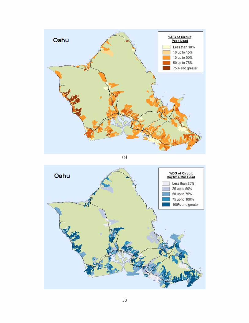
5.2 LocationalValueMaps‐StatusandLessonsLearned Efforts are underway to continuously improve the internal GIS‐based LVM tools and the Online LVM to support better communication of information to the public. Due to recent exponential growth in PV, additional percentage levels above the 15% penetration have been added to the Online LVM to better inform developers and customers where supplemental reviews are likely to be needed. Figure 5.5 provides views of the new 5‐tone LVM for tracking percent penetration levels through 100% of circuit maximums and circuit daytime minimum gross load (load + PV generated load). Because so many of the island feeders are already beyond 15% of maximum PV penetration, customers and developers desired better guidance on penetration on feeders beyond 15% and up to levels that would likely require further review through interconnection studies.
33
(a)

34
(b)
(c)
Figure 5.5. New 5‐tone LVM with a) percentage penetration of circuit maximum, b) percentage penetration by circuit daytime minimum load (DML) and c) all island summary. (Source: HECO)
Figure 5.6. Tracking EV, DR and sensors on internal GIS‐based LVM. (Source: HECO)

35
The LVM has helped the utility and the public track exponential growth of PV on the distribution systems. Staff are now more aware of regions with high penetrations of PV so penetration impacts can be more readily communicated. Prior to the LVMs, the customer‐sited or “behind‐the‐meter” generation was not captured or modeled in any real‐time operation or planning tools. With aggregated distributed generation comparable in MW capacity to a utility generator, tracking and monitoring of high impact DG areas will help improve overall capabilities to integrate renewables and other technologies such as electric vehicles, fast demand respond and energy storage, onto the grids (Figure 5.6).
5.3 RenewableWatch‐StatusandLessonsLearned Following deployment of the Renewable Watch LCD screens, feedback has been overwhelmingly positive. Internally, the content window is now being requested to be displayed in Operations, Power Plants and the Company’s intranet and eventually on the Company’s internet for public use. Recently the content window was released via the Company’s intranet. The information was requested by System Operations, Executives and Planning departments from across the company, who didn’t necessarily have visibility to the LCD screens. Content is also now being developed for sister utilities for the islands of Maui, Molokai, Lanai and Hawaii and will soon be released on the Company’s internet for customer access. With a broader audience, considerable effort has been devoted to clarifying the information on the content window. Additional ITS and Corporate Communication and web‐designers are now being engaged to help enhance the public version of Renewable Watch for the general customer base. The Renewable Watch screens successfully provided a means to visually see how much and from where the behind‐the‐meter generation is coming from across the island. It enabled staff to see the value of Renewables and link to the system in real‐time and provided an intuitive feel to the weather conditions, cloud patterns and irradiance information in near real‐time (15min updates). Utility staff gained new skills designing the content screens using the 4Winds Interactive package which is a widely used industry package for designing large display boards. The advantage of internal resources customizing content realizes both migration to newer technology platforms and workforce development opportunities. Results from this effort continue to add to staff insight and stimulate discussions especially at staff common areas such as lobbies, shuttle stops and preparation areas.
5.4 OperationsIntegration‐StatusandLessonsLearned As this work leverages Task 2 and Task 3 results, it was one of the last visualization efforts to get underway. A number of issues were encountered during the initial scoping of efforts with the EMS vendors and Operators reviewing the work effort. Issues encountered were either technical or change management issues and included

36
Software provider and utility inertia to change
Lack of understanding of needs and connectivity to the new information
Limited experience working with forecasting information
Limited end‐user engagement and buy‐in
Network security concerns
Complex network architecture to sustainably and securely update DG data, forecast data into secure EMS environment
Some of the technical challenges/questions encountered thus far include Issue 1: How to integrate the distributed generation (DG) information within the EMS?
What level of detail – aggregated, three‐phase, single‐phase? How to keep information updated?
Issue 2: What information from the probabilistic wind and solar forecasts is of value and can be used by the EMS? How to use statistical confidence bands and ramp information? How to account for DG installation in the network models without
telemetry? Issue 3: What information is most important to System Operators?
How to display the information and provide updates? System vs distribution view – how much detail to make available?
Current approach and activities for addressing Issues above are summarized below. Resolution for Issue 1: Apply an aggregation approach to account for all the DG systems consistent with the modeling approach in Task 2. The number of individual DG (i.e. rooftop PV systems) installations and lack of telemetry data back to the EMS posed major concerns for the existing computational capability and system logic of the EMS network model. Under the Task 2 DG modeling effort, a methodology had been developed in the planning models to aggregate individual rooftop PVs along single‐phase distribution feeders up to an aggregated, equivalence generator and then map them as a three‐phase balance mode to their respective sub‐transmission substation injection locations. Since the EMS already contained transmission and sub‐transmission substation and RTU point information, using an aggregated PV approach to substation injection locations helped resolve some of the network modeling concerns. Generation information for the aggregated PV was estimated using the probabilistic forecasting data provided by AWS Truepower. Initial results show the value of how variable generation injected at the substation can be predicted using probabilistic forecasts and then integrated into real‐time state estimation and dispatch tools. The substation representation also enabled valuable local variability characteristics (i.e. load variability, load forecasting and management, local micro‐climate impacts on customer use) to be preserved.

37
Mapping DG aggregation data and forecasts into the EMS format required agreement in naming conventions and standard formats among the EMS developers, forecasting provider and the utility. Figure 5.7 and Figure 5.8 show the agreed mapping strategy. The collaborative development environment supported real‐time resolution of data mapping issues.
Figure 5.7. Creating separate Forecast layer by substation and standard name conventions.
Figure 5.8. Mapping of DG forecasts to sub‐transmission and transmission points for the Siemens EMS model. (Source: HECO and Siemens)

38
Resolution for Issue 2: Create functional visualization screens that incorporate real‐time probabilistic forecasts and ramp statistics. Seek input from operators and ITS support and iterate solutions with EMS providers, forecaster and utility users. Creation of new, intuitive visual displays using real‐time forecasts required several iterations and end user feedback. Striking a balance between user perspectives on what information was necessary and what they liked to see was difficult. Figure 5.9 shows proposed alert levels to inform, alarm and review. Figure 5.10 shows the development of interface displays highlighting ramp statistics for wind and solar based on regional aggregations.
Figure 5.9. Typical list‐based alarm page in the Siemens EMS compared to proposed action‐based alerts for action, information and post event training. (Source: Siemens and HECO) Resolution of Issue 3: Actively engage Operations and network support personnel in active feedback. Provide a separate but mirrored environment to develop prototypes and provide hands‐on demonstrations. This task will continue to engage control room operators for feedback and participation throughout the development process. Each EMS vendors will work with the end‐use utilities to
Create more accurate assessments of VER/DER in current state and near‐future situations;
Develop configurable visuals and multi‐level alerts to help system operators monitor and inform action;
Prototype platform showcasing capabilities and gather user feedback on benefits and use;

39
Provide recommendations on standardizing utility data transfer Common Information Model (CIM) protocol, training and application strategies.
Figure 5.10. Prototype of regional forecasts and ramp statistics (Source: Siemens and HECO).

40
6.0 Summary Over the past 2 years, Hawaiian Electric Companies in partnership with SMUD have proactively deployed and successfully piloted new visualization and field monitoring technologies to gain better understanding and visibility to the increasing levels of distributed PV on the grid. Task 4 Visualization efforts leveraged other Tasks conducted as part of the HiP‐PV initiative including modeling, monitoring, forecasting and technical outreach. Utility efforts were also conducted in partnership with industry and vendor providers looking to improve their products through better integration and user feedback. Desired outcomes from the effort included:
Improve management of PV variability and unit commitment with new field information
Reduce utility costs (reserves, heat rate, curtailments) and improve the customer experience
Inform vendors partnerships to help address needs
Engage and build workforce with confidence to change While change was expected, Task 4 efforts pushed traditional utility analytical capability and resulted in the design and development of new data management architecture to support real‐time operations and planning. Efforts also helped develop “insight” on training needs, engaging existing workforce and developing future workforce skillsets. Visualization tools deployed and lessons learned will help utilities build expertise in managing variable DG resources while preserving for locational benefits and accounting for impacts. Some of the Lessons learned include:
1. Technology: a. Utility tools from data processing, data management, analytics and visualization
must be improved, in order to manage the increasing and diverse variable resources.
b. New secure architecture for bi‐directional exchange of data needs management direction and attention (outsource or support with house capabilities)
2. Operational Process: a. The shift toward real‐time, “heads‐up” and dynamic dispatch and load
management requires the convergence of tools, resources and multi‐disciplinary expertise described in this proposal.
b. System management during emergency and contingency events can benefit with higher fidelity data, advance real‐time forecasting and a “heads‐up” but daily operations and dispatch can also be significantly improved and optimized with similar information if they can be incorporated into real‐time operational tools.
3. People/Communication: a. Engage and involve existing vendor partnerships and commitment to provide
product‐based solutions

41
b. Update decision makers often but prototype and test with user group
Visualization tools provided a number of benefits, but the experience gained in developing an approach, engaging the workforce, introducing new process and implementing the technology provided valuable insight to help utilities transform. Experience gained in deploying instrumentation, data analysis and lessons learned in the results of this project have provided benefits to Hawaiian Electric Companies and SMUD and can directly apply to other utilities as their PV penetration levels increase and as they consider monitoring options. Benefits include:
Real‐time information to help utilities better see impact of renewables and integrate information into planning & Ops
Transparency to the public Increase awareness by workforce on value of renewables Sharing of integration experience through industry forums & utility venues Continuing collaboration to seek internal and federal funding Improve management of PV variability and unit commitment with new field information Engage and build workforce & vendor confidence to change Secure, reusable interfaces for data exchange and integration of DG and forecasting
data into the EMS environment. Addressed People, Process & Technology Enhancements
CSI funded effort helped small utilities like HECO & SMUD address high penetration needs and was one of the first efforts to focus awareness of distributed RE impacts on system
Efforts provided impetus for industry (EMS, forecasting, model providers, standards, regulatory, and other utilities) to partner & focus on integrated solutions
Funds jumpstarted lasting initiatives that are being adopted into HECO Companies processes and regulatory recommendations (Interconnection standards, RSWG)
Effort resulted in numerous technical presentations & papers (IEEE, AWEA, SEPA, Distributech, EPRI, CPUC/DOE joint meetings) throughout project period to inform market product development and industry standards development Efforts are leaving a lasting impact by
Encouraging utility/vendor partnering to further develop and operationalize visualization tools (EMS, forecasting, online tools)
Supporting ongoing collaborations on proposals for industry and federal funding (FOA, laboratory & training center) to further develop and implement technologies
Inform standards development (FERC, NERC, IEEE, UL) related to DG and forecasting needs
Contributing new insights to regulatory proceeding and new utility process development

42
Working with a team of industry partners including Siemens, Alstom, AWS Truepower, DNV Kema, Referentia Systems Inc. and various sensors and telecom providers, new visualization and analytical tools in Task 4 were developed with utility feedback, jointly piloted in the field transitioned into implementation and are now being utilized to help manage with very high penetrations of variable DG. Utility partnership in enhancing vendor products has also been positively received by the partners on this team. Building on the results of the CSI funding, this same project team was recently awarded a US DOE Sunshots grant to continue implementation efforts and integrate the forecasting data, aggregated DG modeling tools and field data into System Operation’s Energy Management System (EMS) decision tools. Siemens and Alstom EMS tools are used by Hawaiian utilities and a number of western utilities including California IOUs and the CaISO. The development and deployment of a robust architecture to support renewable integration and data management needs will continue to evolve with new technologies. However without a common platform to centralize information and conduct such analysis, it will be increasingly difficult to manage large volumes of renewable information and to effectively utilize grid intelligence from customers (AMI) to inform future automation needs and optimize use of new technologies such as faster demand response (FastDR) and customer options. The new visualizations are being expanded to provide information to customers and support communications of renewable development to customers and policy makers.
43
7.0 References
1. Sacramento Municipal Utility District website, www.smud.org. 2. Hawaiian Electric website, www.heco.com. 3. L. Dangelmaier, D. Nakafuji and R. Kaneshiro, “Tools Used for Handling Variable Generation
in the Hawaii Electric Light Company Control Center,” IEEE 2012 PES Conference, Proceedings Paper, San Diego, CA, July 2012.
4. Hawaii Rule 14H Service Connections and Facilities on Customer’s Premises, www.heco.com/vcmcontent/FileScan/PDF/EnergyServices/Tarrifs/HECO/HECORules14.pdf.
5. California Rule 21 Standard Interconnection Agreement, www.cpuc.ca.gov/PUC/energy/Procurement/LTPP/rule21.htm.
6. E.M. Stewart, T.P. Aukai, S.D.J. MacPherson, B.P. Quach, D. Nakafuji and R. Davis, “A Realistic Irradiance‐based Voltage Flicker Analysis of PV Applied to Hawaii Distribution Feeders,” IEEE 2012 PES Conference, Proceedings Paper, San Diego, CA, July 2012.
7. D. Nakafuji and T. Aukai, “Proactive Approach Process: Cluster Evaluation for Distributed Generation in Hawaii,” Distributech, Conference Presentation, San Diego, CA, January 2013.
8. California Solar Initiative (CSI RD&D) website, SMUD/HECO High Penetration PV Initiative http://www.calsolarresearch.org/component/option,com_sobipro/Itemid,0/pid,54/sid,66/
9. E. Sison‐Lebrilla and D. Nakafuji, “HiP‐PV: PV Visualization & Integration Update,” CPUC‐DOE High Penetration Solar Forum 2013, San Diego, CA, February 2013.
10. Hawaii Renewable Energy Development Venture (HREDV) website, Documentary Series, Referentia/HECO Partnership, http://www.hawaiirenewable.com/referentia/.
11. D. Nakafuji, C. Reynolds and M. Shawver, “Grid Renewables Integration Decision Support System (GRIDS2),” HREDV Program FactSheet, http://www.hawaiirenewable.com/wp‐content/uploads/2012/04/SEPA_conference‐one‐pager.pdf.
12. D. Nakafuji, M. Shawver, L. Gouveia, T. Sokugawa, and I. Koga, “Enabling Intelligent Grids: A Next‐Generation, Fast and Secure Analytics for Utilities,” EPRI Smart Distribution and Power Quality Conference and Exhibition, Chicago, IL, June 2013.
13. Hawaiian Electric Online LVM, http://www.heco.com/portal/site/heco/lvmsearch. 14. Four Winds Interactive product website, http://www.fourwindsinteractive.com/products/ 15. D. Nakafuji, J. Zack, A. Brightbill, L. Gouveia and J. Friedman, “Integrating Real‐time
Solar & Wind Integrated Forecasting Tool (SWIFT) for Hawaii Utility Operation,” American Wind Energy Association AWEA 2013, Conference Presentation, Chicago, IL, May 2013.
Related Documents


