High Frequency Wobbles: A Write Clock Generation Method for Rewritable DVD That Enables Near Drop-In Compatibility with DVD-ROMs Daniel Abramovitch, David Towner, Craig Perlov, Josh Hogan, Michael Fischer, Carol Wilson, Ilkan C ¸okg¨or and Carl Taussig Hewlett-Packard Laboratories, Storage Technologies Department, 1501 Page Mill Road, M/S 4U-12, Palo Alto, CA 94304 USA August 2, 1999 ABSTRACT This paper describes a write clock generation scheme for rewritable DVD which eliminates a major issue for drop-in compatibility with DVD-ROMs. The method used is to co-locate a high frequency clock reference next to the data using a wobble groove. This enables bit accurate edits on rewritable DVD media. Keywords: High Frequency Wobbles, DVD-ROM Compatibility, Optical Recording, Write Clock Generation To appear in the Proceedings of ISOM/ODS’99 1. MOTIVATION This paper presents an overview of a new method of write clock generation on rewritable DVD drives that eliminates many of the problems associated with reading rewritable disks in DVD-ROM drives. It is believed that such a format will provide tremendous benefits to the end user, making it possible to edit content on a rewritable DVD disk and then play that same disk in a conventional DVD-ROM player. From a large set of potential problems, it appears that the real issues can be reduced to two: • smaller changes in reflectivity on phase-change media and • a much tighter clocking requirement caused by the need to eliminate edit gaps. Of these, the first is an issue for roughly half of the commercial DVD players in the world today. This issue can be overcome in the remainder with a simple circuit change in the AGC of the reader. It is the latter issue which is a problem. As shown in the bottom drawing of Figure 1, DVD-ROM disks have no edit gaps or physical sector marks. This is in contrast to conventional rewritable formats (the top two drawings of Figure 1) which need these gaps to accommodate imprecision in the write clock which would otherwise cause data loss at the end of data fields. 1–5 In order to match the DVD-ROM format, 6 a rewritable format must move away from what is depicted in the top two drawings to the bottom drawing of Figure 1. 2. HIGH FREQUENCY WOBBLE CLOCK In order to eliminate edit gaps and other in line sector information in a rewritable format, a new clocking scheme was devised that uses high spatial frequency groove edge oscillations (wobbles) to generate clock signals. This has the advantage that it co-locates clock reference with data, yielding a high fidelity, high frequency clock reference, as shown schematically in the left half of Figure 2. Using this, one can lock a narrow band phase-locked loop (PLL), as shown in Figure 3, to the oscillation frequency to generate the write clock. Addressing information can be encoded into the wobble itself using a variety of methods to eliminate the need for physical sector marks. Having a continuous clock co-located with the data is more precise and robust than intermittent clocks. The PLL can average over many clock cycles to ignore defects more easily. Furthermore, spindle runout, disk eccentricity and thermal variations have far less effect on the write clock. This means that there is virtually no drift between clock samples, allowing for the elimination of edit gaps. By encoding address information in the wobble itself, the Send correspondence to Daniel Abramovitch, E-mail: [email protected], Phone: (650) 857-3806, FAX: (650) 857-7704 1

Welcome message from author
This document is posted to help you gain knowledge. Please leave a comment to let me know what you think about it! Share it to your friends and learn new things together.
Transcript

High Frequency Wobbles: A Write Clock Generation Methodfor Rewritable DVD That Enables Near Drop-In Compatibility
with DVD-ROMs
Daniel Abramovitch, David Towner, Craig Perlov, Josh Hogan,Michael Fischer, Carol Wilson, Ilkan Cokgor and Carl Taussig
Hewlett-Packard Laboratories, Storage Technologies Department,1501 Page Mill Road, M/S 4U-12, Palo Alto, CA 94304 USA
August 2, 1999
ABSTRACT
This paper describes a write clock generation scheme for rewritable DVD which eliminates a major issue for drop-incompatibility with DVD-ROMs. The method used is to co-locate a high frequency clock reference next to the datausing a wobble groove. This enables bit accurate edits on rewritable DVD media.
Keywords: High Frequency Wobbles, DVD-ROM Compatibility, Optical Recording, Write Clock Generation
To appear in the Proceedings ofISOM/ODS’99
1. MOTIVATION
This paper presents an overview of a new method of write clock generation on rewritable DVD drives that eliminatesmany of the problems associated with reading rewritable disks in DVD-ROM drives. It is believed that such a formatwill provide tremendous benefits to the end user, making it possible to edit content on a rewritable DVD disk andthen play that same disk in a conventional DVD-ROM player. From a large set of potential problems, it appearsthat the real issues can be reduced to two:
• smaller changes in reflectivity on phase-change media and
• a much tighter clocking requirement caused by the need to eliminate edit gaps.
Of these, the first is an issue for roughly half of the commercial DVD players in the world today. This issue can beovercome in the remainder with a simple circuit change in the AGC of the reader. It is the latter issue which is aproblem. As shown in the bottom drawing of Figure 1, DVD-ROM disks have no edit gaps or physical sector marks.This is in contrast to conventional rewritable formats (the top two drawings of Figure 1) which need these gaps toaccommodate imprecision in the write clock which would otherwise cause data loss at the end of data fields.1–5 Inorder to match the DVD-ROM format,6 a rewritable format must move away from what is depicted in the top twodrawings to the bottom drawing of Figure 1.
2. HIGH FREQUENCY WOBBLE CLOCK
In order to eliminate edit gaps and other in line sector information in a rewritable format, a new clocking schemewas devised that uses high spatial frequency groove edge oscillations (wobbles) to generate clock signals. This hasthe advantage that it co-locates clock reference with data, yielding a high fidelity, high frequency clock reference, asshown schematically in the left half of Figure 2. Using this, one can lock a narrow band phase-locked loop (PLL), asshown in Figure 3, to the oscillation frequency to generate the write clock. Addressing information can be encodedinto the wobble itself using a variety of methods to eliminate the need for physical sector marks.
Having a continuous clock co-located with the data is more precise and robust than intermittent clocks. ThePLL can average over many clock cycles to ignore defects more easily. Furthermore, spindle runout, disk eccentricityand thermal variations have far less effect on the write clock. This means that there is virtually no drift betweenclock samples, allowing for the elimination of edit gaps. By encoding address information in the wobble itself, the
Send correspondence to Daniel Abramovitch, E-mail: [email protected], Phone: (650) 857-3806, FAX: (650) 857-7704
1

Figure 1. Optical disk formats on rewritable and ROM media. The top diagram represents sector formats on driveswhere synchronization, servo, and address fields as well as an edit gap are time multiplexed down the track withthe data. This is the current norm in both sampled servo magnetic and optical disk drives. The middle diagramrepresents sector formats on drives which do not obtain their servo information from the sector header, but still timemultiplex the remaining fields with the data. This was common in dedicated servo magnetic drives, which have fallenout of favor, and is the norm in optical drives where the grooves or pits provide a continuous pattern for the trackingservo. The top two formats are the prevalent methods used in rewritable magnetic and optical media. The bottomdigram represents a typical format for ROM media. Because the media is mastered once at the factory, no physicalsector marks are needed. Instead, logical synchronization and address fields are included within the data.
Figure 2. High frequency wobbles. On the left is a perspective schematic of high frequency wobbles. On the rightis an SEM image of 4.7 GB, 30 nm peak to peak wobble disk. Wobbles with amplitudes of up to 50 nm peak to peakhave been tested.
embossed sector information leaves the entire track available for the data. This clears the way to make the datasector continuous, as in the DVD-ROM format.6
The design of the PLL is linked to the design of the clock reference signal. The shape of the modulation transferfunction (MTF)7 of the optical system is typically falling off at higher frequencies. This means that higher frequencysignals are attenuated more than lower frequency signals, finally reaching 0 at the optical cutoff frequency. Thus,there is both an absolute and a practical limit on the spatial frequencies that can be resolved, leading to a upperlimit on the clock reference frequency that can be encoded on the disk. Generally speaking, the lower the referenceclock frequency, the higher the signal to noise of the signal at the detector.
The write clock, on the other hand, typically requires a clock frequency that is higher than the allowable clock
2

N
fr
N fr
Write Clock
Phase-Locked
to Reference
Bandpass
Filter
Loop
Filter
High
Frequency
LP Filter
Voltage
Controlled
Oscillator
fr
Phase
Detector
fr
Clock
Signal
Reference
ψ ψf
Figure 3. A Harmonic Locking PLL is used to generate the write clock.
reference frequency. A relatively standard solution to this problem is what is known in the PLL field as a harmoniclocking PLL or simply a harmonic locking loop, shown in Figure 3. A harmonic locking loop has the property thatwhile it is phase locked to the reference signal, it generates a clock signal at N × reference clock frequency. Variantsof this are available that allow N to be a non-integer number. However, a consequence of using such a loop is thatit boosts the clock jitter by N. Thus, for a given desired write clock, one would want to minimize N for a givenwrite clock frequency. To do this, one would wish to maximize the reference clock frequency. A practical choice fora reference clock frequency must trade off between the lower signal to noise of a higher frequency reference and theincreased jitter of a lower frequency reference.
3. IMPLEMENTATION ISSUES
While there are many possibilities for implementing such a scheme, the choice of the specific physical encodingmethod depends upon the available spatial frequencies, the available signal detection methods, and a desire toavoiding interference between clock and data/servo signals.
This format was aimed at a consumer application of computers and digital video. In such markets, cost is acritical factor and therefore minimizing the cost of parts by using industry standard optical components was seen asthe path with the highest probability of success as a product. Once it was decided that an industry standard set ofoptics (0.6-0.65 NA lens, 635-650 nm laser) would be used, the possibility of putting the clock frequency above thedata frequencies was eliminated. Putting the clock frequency below the frequency range at which there is substantialdata content would have resulted in a write clock with too much jitter to eliminate the edit gaps.
The solution is a high frequency wobble groove – an in-phase oscillation of the groove walls – as the methodfor encoding the reference clock. This has the advantage that it is nominally invisible to data detection in thecentral aperture mode (CAD), but yet easily detectable in the radial push pull (RPP) servo signal outside of servobandwidth. This allows the wobble signal to be encoded within the range of data frequencies with little interferencebetween the two signals. Some spectra of typical signals are shown in Figure 4.
These choices provide near bit accurate editing. However, it has been noticed that linkless editing must take intoaccount issues with the preheating of the media at the edit in and edit out points. As shown in Figure 5, a typicalwrite strategy used in phase change recording tends to make single bit errors when used in linkless editing. At editin, the first mark is too short, while the first space is too long. At edit out, both the mark and space are too long,albeit by different amounts. The solution is to make slight adjustments to write strategy at edit in and edit out bits.The length of the start and stop pulses are adjusted to compensate for the initial and final thermal effects, as shownin Figure 6. These final adjustments provide bit accurate editing without any bit errors.
4. RESULTS
The signal read back from the high frequency wobble becomes the reference clock signal for the system. The writeclock is generated by using a harmonic locking PLL8,9 as shown in Figure 3 to boost the reference clock frequency to
3

1 2 3 4 5 6 7 8 9 10−100
−90
−80
−70
−60
−50
−40
−30
−20
−10
0
Freq (MHz)
Dat
a S
pect
rum
(dB
m)
Measurement da_tst2_rd_3A: Data Spectrum
32768 points in recordSpectrum Analyzer SimulationResolution Bandwidth: 30.00 kHz
Disk # B7201−3ABand # 8Spindle at 715 RPMUnnormalized Signals7/31/98, 4:39 PM
Amplitude of −65.19 dBm at wobble frequency
1 2 3 4 5 6 7 8 9 10−100
−90
−80
−70
−60
−50
−40
−30
−20
−10
0
Freq (MHz)
Dat
a S
pect
rum
(dB
m)
Measurement da_tst2_nd_3A: Data Spectrum
32768 points in recordSpectrum Analyzer SimulationResolution Bandwidth: 30.00 kHz
Disk # B7201−3ABand # 8Spindle at 715 RPMUnnormalized Signals7/31/98, 4:37 PM
Amplitude of −62.72 dBm at wobble frequency
1 2 3 4 5 6 7 8 9 10−100
−90
−80
−70
−60
−50
−40
−30
−20
−10
0
Freq (MHz)
Wob
ble
Spe
ctru
m (
dBm
)
Measurement da_tst2_rd_3A: Wobble Amplitude Spectrum
32768 points in recordSpectrum Analyzer SimulationResolution Bandwidth: 30.00 kHz
Disk # B7201−3ABand # 8Spindle at 715 RPMUnnormalized Signals7/31/98, 4:39 PM
Peak of −42.07 dBm at 2.94 MHz
1 2 3 4 5 6 7 8 9 10−100
−90
−80
−70
−60
−50
−40
−30
−20
−10
0
Freq (MHz)
Wob
ble
Spe
ctru
m (
dBm
)
Measurement da_tst2_nd_3A: Wobble Amplitude Spectrum
32768 points in recordSpectrum Analyzer SimulationResolution Bandwidth: 30.00 kHz
Disk # B7201−3ABand # 8Spindle at 715 RPMUnnormalized Signals7/31/98, 4:37 PM
Peak of −38.08 dBm at 2.94 MHz
Figure 4. Crosstalk between data and wobbles is small as shown in this example. The left side column of plotscontains spectrums taken from the data channel (sum signal). The right side column of plots contains spectrumstaken from the wobble channel (radial push-pull). The top two plots are spectrums when random data is recordedon the track. The bottom two plots are spectrums with no data recorded on the track. Note that the wobble signalis visible in the data channel when no data is present, but the signal level of random data is far higher. This resultsin the wobble having no significant effect on the data channel. Likewise, random data can be seen in the wobblechannel, but its signal level is far below that of the wobble, leading to no significant effect on the write clock. Theseresults are robust to offtrack, defocus, beam walk, and tilt.
Offtrack: ± 30 nmDefocus: ± 0.8 µmBeam Walk: ± 6% of beamRadial Tilt: ± 0.3◦
Tangential Tilt: ± 0.6◦
Table 1. Summery of wobble clock and data jitter margins from measurements.
that of a write clock. The limiter preceding the loop makes it insensitive to amplitude changes resulting from laserpower changes when switching between reading and writing.
The resulting write clock is very accurate with jitter < 300 pS. This is < 1 % of a data clock bit (for T ≈ 38 nSand for wobbles with a period of 9T). Furthermore, the clock is orthogonal to the data; that is, the data and thewobble are detected in different ways, as noted in Section 3.
The resulting system is one that makes bit accurate editing a reality. A few typical examples of this are shown
4

6T6T6T
Time
Write
Read
Erase
Mark at Edit In
Is Too Short
Edit In
Point
La
se
rPo
we
r
Figure 5. Due to the heating of the media, there are problems with a typical write strategy when used in linklessediting. At edit in, the first mark is too short, while the first space is too long. At edit out, both the mark and spaceare too long, albeit by different amounts.
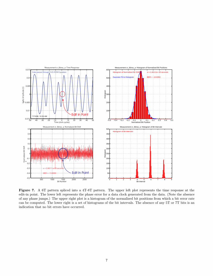
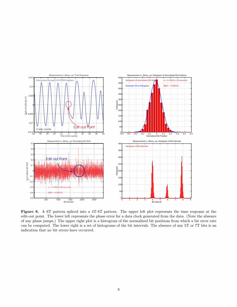
in Figures 7, 8, and 9, where a 6T pattern (6T mark, 6T space) is spliced into a 4T-8T (4T mark, 4T space, 8Tmark, 8T space) pattern with negligible phase error. Figure 7 shows a measurement of an edit which is centered onthe edit in position. Note the lack of bit errors or distortion of the data signal at the edit point. Figure 8 showssimilar results, albeit centered at the edit out point. Figure 9 shows an edit in of 2 6T bits.
Finally, the clock is very robust to a variety of conditions as shown in Table 1, which summarizes the marginsfrom the measurements in Figures 10 and 12. Furthermore, results not presented here have shown robustness totemperature and spindle variations. An example of the insensitivity to offtrack is shown in Figure 10. In this case, along write was done with 4T-8T data and then 6T edits were done at various offtrack conditions. The data was thenread with the lens on track and the jitter measured. The experiment schematic is shown in the left half of Figure 10.The jitter results are shown in the right half of the figure. Note that there is no increase in the data jitter as theedit moves off track. A single measurement of this offtrack condition is shown in Figure 11. Note that although theedit done with the actuator offtrack by 30 nanometers has produced a slight phase shift in the data clock at theedit point, this is not significant and does not result in any bit errors. Likewise the jitter plots in Figure 12 showrobustness to defocus, decenter (beam walk), radial tilt, and tangential tilt.
5. CONCLUSIONS
Results such as this have been reliably repeated for a variety of edits and a variety of disturbance conditions. Theyindicate that the scheme has good robustness to radial and tangential tilt, offtrack, defocus, and modulation of thewobble for addressing.
The resulting write clock enables bit accurate editing. The results depicted here enable a rewritable format that iscloser to the DVD-ROM specification than any these authors have seen. Furthermore, it is is the only demonstrationto date that enables random rewritability in a DVD-ROM compatible format. Results such as these have been usedin the creation of the 4.7GB DVD+RW format. Linkless editing forms a key property of this format.
REFERENCES
1. A. B. Marchant, Optical Recording: A Technical Overview, Addison-Wesley Longman, Inc., Reading, MA, 1990.ISBN 0-201-76247-1.
2. K. C. Pohlmann, The Compact Disc Handbook, A-R Editions, Inc., Madison, WI, second ed., 1992. ISBN0-89579-300-8.
5

La
se
rPo
we
r
La
se
rPo
we
r
6T6T6T6T
Ed
itIn
Mo
dific
atio
n
La
se
rPo
we
r
La
se
rPo
we
r
6T6T6T6T
Ed
itO
utM
od
ific
atio
n
Figure 6. Adjustments to write strategy in edit in and edit out: adjust length of start and stop pulses to compensate.These lines show modifications to the write strategy. The dashed lines show the original write strategy, while thesolid lines show the modified strategy. The top two drawings are for edit in: the first pulse of a leading mark isstarted slightly early, while the first pulse of a leading space is started slightly late. The lower two drawings arefor edit out: both the pulses for a trailing space and a trailing mark are truncated early so as not to overwrite thepreexisting data.
3. R. L. Comstock and M. L. Workman, “Data storage on rigid disks,” in Magnetic Recording Handbook, C. D. Meeand E. D. Daniel, eds., vol. 2, ch. 2, pp. 655–771, Mc Graw Hill, New York, NY, 1990. ISBN 0-07-041274-X.
4. ECMA, 120 mm DVD Rewritable Disk (DVD-RAM). ECMA, 114 Rue du Rhone,CH-1204 Geneva Switzerland,http://www.ecma.ch/, February 1998.
5. ECMA, Data Interchange on 120 mm Optical Disk using +RW Format - Capacity: 3,0 Gbytes and 6,0 Gbytes.ECMA, 114 Rue du Rhone,CH-1204 Geneva Switzerland, http://www.ecma.ch/, April 1998.
6. ECMA, ECMA Specification: 120 mm DVD- Read-Only Disk. ECMA, 114 Rue du Rhone,CH-1204 GenevaSwitzerland, http://www.ecma.ch/, December 1997.
7. G. Bouwhuis, J. Braat, A. Huijser, J. Pasman, G. van Rosmalen, and K. S. Immink, Principles of Optical DiscSystems, Adam Hilger, Ltd., Bristol, England and Boston, MA, 1985. ISBN 0-85274-785-3, out of print.
8. F. M. Gardner, Phaselock Techniques, John Wiley & Sons, New York, NY, second ed., 1979. ISBN 0-471-04294-3.
9. D. H. Wolaver, Phase-Locked Loop Circuit Design, Advanced Reference Series & Biophysics and BioengineeringSeries, Prentice Hall, Englewood Cliffs, New Jersey 07632, 1991. ISBN 0-13-662743-9.
6
Edit in PointEdit in Point
Da
taA
mp
litud
e(V
)N
orm
aliz
ed
Bit
Shift
Edit In PointEdit In Point
−0.5 −0.4 −0.3 −0.2 −0.1 0 0.1 0.2 0.3 0.4 0.50
100
200
300
400
500
600
Normalized Bit Position
His
togr
am
Measurement cr_6tinss_a: Histogram of Normalized Bit Positions
Histogram of Normalized Bit Shifts
Gaussian Fit to Histogram
σ = 2.46111e−09 seconds
BER = −13.8393
0 1 2 3 4 5 6 7 8 90
50
100
150
200
250
300
350
400
450
500
Bit Interval
His
togr
am
Measurement cr_6tinss_a: Histogram of Bit Intervals
Histogram of Bit Intervals
Figure 7. A 6T pattern spliced into a 4T-8T pattern. The upper left plot represents the time response at theedit-in point. The lower left represents the phase error for a data clock generated from the data. (Note the absenceof any phase jumps.) The upper right plot is a histogram of the normalized bit positions from which a bit error ratecan be computed. The lower right is a set of histograms of the bit intervals. The absence of any 5T or 7T bits is anindication that no bit errors have occurred.
7
Edit out PointEdit out Point
Da
taA
mp
litud
e(V
)
Edit out PointEdit out Point
No
rma
lize
dBit
Shift
−0.5 −0.4 −0.3 −0.2 −0.1 0 0.1 0.2 0.3 0.4 0.50
50
100
150
200
250
300
350
400
450
500
Normalized Bit Position
His
togr
am
Measurement cr_6tinss_oa: Histogram of Normalized Bit Positions
Histogram of Normalized Bit Shifts
Gaussian Fit to Histogram
σ = 3.10067e−09 seconds
BER = −8.98732
0 1 2 3 4 5 6 7 8 90
50
100
150
200
250
300
350
400
Bit Interval
His
togr
am
Measurement cr_6tinss_oa: Histogram of Bit Intervals
Histogram of Bit Intervals
Figure 8. A 6T pattern spliced into a 4T-8T pattern. The upper left plot represents the time response at theedit-out point. The lower left represents the phase error for a data clock generated from the data. (Note the absenceof any phase jumps.) The upper right plot is a histogram of the normalized bit positions from which a bit error ratecan be computed. The lower right is a set of histograms of the bit intervals. The absence of any 5T or 7T bits is anindication that no bit errors have occurred.
8

Edit in PointEdit in Point
Edit out PointEdit out Point
Da
taA
mp
litud
e(V
)
500 1000 1500 2000 2500−0.5
−0.4
−0.3
−0.2
−0.1
0
0.1
0.2
0.3
0.4
0.5
Bit Number
Nor
mal
ized
Bit
Shi
ft
Measurement cr_zoom: Normalized Bit Shift
σ = 2.95779e−09 seconds
BER = −9.86655
−0.5 −0.4 −0.3 −0.2 −0.1 0 0.1 0.2 0.3 0.4 0.50
50
100
150
200
250
300
350
400
450
500
Normalized Bit Position
His
togr
am
Measurement cr_zoom: Histogram of Normalized Bit Positions
Histogram of Normalized Bit Shifts
Gaussian Fit to Histogram
σ = 2.95779e−09 seconds
BER = −9.86655
0 1 2 3 4 5 6 7 8 90
50
100
150
200
250
300
350
400
Bit Interval
His
togr
am
Measurement cr_zoom: Histogram of Bit Intervals
Histogram of Bit Intervals
Figure 9. A 2 bit 6T pattern spliced into a 4T-8T pattern. The upper left plot represents the time response at theedit-in and edit-out point. The lower left represents the phase error for a data clock generated from the data. (Notethe absence of any phase jumps.) The upper right plot is a histogram of the normalized bit positions from which abit error rate can be computed. The lower right is a set of histograms of the bit intervals. The absence of any 5T or7T bits is an indication that no bit errors have occurred.
DATA DATA
on trackon track
10 nm offtrack10 nm offtrack
20 nm offtrack20 nm offtrack
30 nm offtrack30 nm offtrack
EDIT
−30 −20 −10 0 10 20 300
1
2
3
4
5
6
7
8
9
10
Approximate Offtrack (nm)
Dat
a Ji
tter
(%)
Data Jitter vs. Offtrack: Disk B7201−4A
Data On Track
Jitter % = 100(σ/Tc)
Figure 10. Data jitter versus offtrack insert on 30 nm wobble disk. A long write was done with a 4T-8T pattern.Then edit inserts were made with 6T pattern at various offtrack conditions. Finally, the data jitter was calculatedwith lens on track using the data channel model.
9

−50 −40 −30 −20 −10 0 10 20 30 40 50−0.015
−0.01
−0.005
0
0.005
0.01
0.015
Time (clock cycles)
Dat
a A
mpl
itude
(V
)
Measurement ot_m30nm_b: Time Response
9/8/98, 4:36 PM
Data passed through DVD−ROM Equalizer.
200 400 600 800 1000 1200 1400−0.5
−0.4
−0.3
−0.2
−0.1
0
0.1
0.2
0.3
0.4
0.5
Bit Number
Nor
mal
ized
Bit
Shi
ft
Measurement ot_m30nm_b: Normalized Bit Shift
σ = 2.60889e−09 seconds
BER = −12.2353
−0.5 −0.4 −0.3 −0.2 −0.1 0 0.1 0.2 0.3 0.4 0.50
50
100
150
200
250
300
Normalized Bit Position
His
togr
am
Measurement ot_m30nm_b: Histogram of Normalized Bit Positions
Histogram of Normalized Bit Shifts
Gaussian Fit to Histogram
σ = 2.60889e−09 seconds
Jitter = 6.939911% of Tc
BER = −12.2353
0 1 2 3 4 5 6 7 8 90
20
40
60
80
100
120
140
160
180
200
Bit Interval
His
togr
am
Measurement ot_m30nm_b: Histogram of Bit Intervals
Histogram of Bit Intervals
Figure 11. Offtrack measurement on 30 nm wobble disk. This case is offtrack by -30 nm. Note the absence oferrors. Offtrack ranges in ±30 nm produce no bit errors.
10

−0.8 −0.6 −0.4 −0.2 0 0.2 0.4 0.6 0.80
0.1
0.2
0.3
0.4
0.5
0.6
0.7
0.8
0.9
1
Defocus (um)
Wob
ble
Clo
ck J
itter
(%
)
TIA Meas. of Wobble Clock Jitter vs. Beam Defocus (um)
Disk # C9841−5ABand # 8
Disk Wobble Amplitude 40 nm9/15/98, 3:00 PM
Jitter % = 100(σ/Tc)
Time Delay Around TrackNo Data Random Data
1 ms5 ms10 ms15 ms
1 ms5 ms10 ms15 ms
−0.6 −0.4 −0.2 0 0.2 0.4 0.60
0.1
0.2
0.3
0.4
0.5
0.6
0.7
0.8
0.9
1
Wob
ble
Clo
ck J
itter
(%
)
Tilt Angle (deg)
Wobble Signal Jitter vs. Radial Tilt Angle
Disk # C9841−5ABand # 8
Disk Wobble Amplitude 40 nm9/4/98, 1:00 PM
Jitter % = 100(σ/Tc)
Time Delay Around Track
1 ms3 ms5 ms7 ms
9 ms11 ms13 ms15 ms
−8 −6 −4 −2 0 2 4 6 80
0.1
0.2
0.3
0.4
0.5
0.6
0.7
0.8
0.9
1
Decenter (% of Beam)W
obbl
e C
lock
Jitt
er (
%)
TIA Meas. of Wobble Clock Jitter vs. Beam Walk (% of beam)
Disk # C9841−5ABand # 8
Disk Wobble Amplitude 40 nm9/15/98, 3:00 PM
Jitter % = 100(σ/Tc)
Time Delay Around TrackNo Data Random Data
1 ms5 ms10 ms15 ms
1 ms5 ms10 ms15 ms
−0.6 −0.4 −0.2 0 0.2 0.4 0.60
0.1
0.2
0.3
0.4
0.5
0.6
0.7
0.8
0.9
1
Wob
ble
Clo
ck J
itter
(%
)
Tilt Angle (deg)
Wobble Signal Jitter vs. Tangential Tilt Angle
Disk # C9841−5ABand # 8
Disk Wobble Amplitude 40 nm9/4/98, 1:00 PM
Jitter % = 100(σ/Tc)
Time Delay Around Track
1 ms3 ms5 ms7 ms
9 ms11 ms13 ms15 ms
Figure 12. Wobble clock jitter measurements from a Time Interval Analyzer (TIA). Jitter was measured from 2000leading edges per revolution for 50 revolutions. Measurements were done at different down the track positions bydelaying the counting of the first edge by an adjustable number of milliseconds. The upper left plot is a measurementof jitter versus defocus. The upper right plot is a measurement of jitter versus decenter. Measurements were madeboth with random data on the track and without data on the track. The lower left plot is a measurement of jitterversus radial tilt. The lower right plot is a measurement of jitter versus tangential tilt. In both of these, there wasrandom data both on the track being measured and on the two adjacent tracks. Line plots denote averages of themultiple down the track measurements for a given x-axis condition. Solid line plots are averages of measurementswith data on the track. The dashed lines in the top two plots denote averages of measurements with no data on thetrack. Finally, every condition was measured twice at the same down the track position, and is represented by thesame symbol. The variation on a given plot between any two similar symbols that share a common down x-ordinategives an estimate as to the accuracy of the measurement process itself.
11
Related Documents


![MB81EDS516545 - Fujitsu...CK, CK Input Clock CKE Input Clock Enable CS Input Chip Select RAS Input Row Address Strobe CAS Input Column Address Strobe WE Input Write Enable BA[1:0]](https://static.cupdf.com/doc/110x72/60e98dfc20357b2d2330df42/mb81eds516545-fujitsu-ck-ck-input-clock-cke-input-clock-enable-cs-input-chip.jpg)