1 HIGH FREQUENCY WELDING HANDBOOK

Welcome message from author
This document is posted to help you gain knowledge. Please leave a comment to let me know what you think about it! Share it to your friends and learn new things together.
Transcript
1
HIGH FREQUENCY
WELDING HANDBOOK
2
CONTENTS
PREFACE (iii) CONTENTS (iv) HEALT AND SAFETY (vii) GENERAL (vii) HF WELDING HAZARDS (vii) 1. INTRODUCTION 1-1 1.1 WHAT IS HIGH FREQUENCY WELDING? 1-1 1.2 TYPICAL END PRODUCTS 1-2 1.3 HISTORY 1-2 1.4 THE FEDERATION OF HIGH FREQUENCY WELDERS 1-2 2. THE HF WELDING PROCESS 2-1 2.1 WHY USE HIGH FREQUENCY POWER? 2-1 2.2 PRATICAL HF WELDING 2-2 2.3 BARRIER MATERIALS 2-2 2.4 SETTING MACHINE CONTROLS 2-3 2.4.1 Pressure 2-4 2.4.2 Press Stroke Adjustment 2-4 2.4.3 Depth of Sink Control 2-4 2.4.4 HF Power Control 2-4 2.4.5 Welding Tim 2-5 2.4.6 Cooling Time 2-5 2.4.7 Platen Temperature 2-5 3. MACHINERY 3-1 3.1 GENERAL 3-1
3
3.2 HF WELDING 3-1 3.3 MAJOR COMPONENTS 3-1 3.3.1 HF Power Generator 3-2 3.3.2 Press 3-2 3.3.3 Control System 3-3 3.3.4 Handling Mechanisms 3-4 3.4 TYPES OF MACHINE 3-5 3.4.1 Foot Pedal 3-5 3.4.2 Roll Fed Linear 3-6 3.4.3 Rotary Table 3-7 3.4.4 Shuttle Operated 3-8 3.5 TOOLING 3-9 3.5.1 Tooling Assembly 3-9 3.5.2 Welding Rule 3-10 3.5.3 Packing 3-11 3.6 PREPARATION FOR WELDING 3-12 4. HF WELDING TECHNIQUE 4-1 4.1 MACHINE SETTING 4-1 4.1.1 Preparation 4-1 4.1.2 Setting the Controls 4-1 4.2 WELD AREA CALCULATIONS 4-3 4.2.1 HF Generator Considerations 4-3 4.2.2 Basic Calculation of Required Power 4-3 4.2.3 Realistic Calculation of Required HF Power 4-4 4.2.4 Pratical Solution 4-6 4.3 APPLIQUE’ WELDING 4-8 4.3.1 Cost 4-8 4.3.2 Applications 4-8 4.3.3 Welding 4-8 5. MAINTENANCE 5-1 5.1 PREVENTIVE MAINTENANCE 5-1 5.1.1 Cleaning 5-2 5.1.2 Lubrication 5-2 5.1.3 Inspection 5-2 5.1.4 Testing 5-2 6. FAULT FINDING 6-1 6.1 HF WELDING MACHINES 6-1 6.2 WELDS 6-3 7. MATERIALS USED IN HF WELDING 7-1 7.1 NATURE AND PROPERTIES OF PVC 7-1 7.2 PVC CHEMICAL STRUCTURE 7-1 7.3 PVC COMPOSITIONS 7-2 7.3.1 Rigid PVC Compounds 7-2 7.3.2 Flexible PVC Compounds 7-2 7.3.3 Additives used in the Industry 7-2 7.4 PROPERTIES OF PVC SHEET 7-3 7.5 FACTORS THAT GOVERN A SATISFACTORY WELDED PRODUCT 7-4 7.6 TYPES OF PVC SHEET AND THEIR USES 7-5 7.7 THE ROLE OF PLASTICISER IN FLEXIBLE PVC SHEETING 7-5 7.7.1 Introduction 7-5 7.7.2 Why are a Range of Plasticisers Used? 7-5 7.7.3 What is Plasticiser Migration and Why Does it Happen? 7-6 7.7.4 How Can I Ensure that Plasticiser Migration Not Happen? 7-7
4
7.8 COLD CRACK PROBLEMS WITH STATIONERY PRODUCTS 7-7 7.8.1 Introduction 7-7 7.8.2 Possible Causes 7-7 7.8.3 Summary 7-8 7.9 COLOUR MATCHING OF FLEXIBLE PVC SHEETING 7-8 7.9.1 Opacity of Colour 7-9 7.9.2 Types of Pigment used in Flexible PVC Sheeting 7-9 7.9.3 Variation in Colour Shade under Different Lighting 7-9 7.10 THE IMPORTANCE OF UNIFORM GAUGE IN CALENDERED PVC SHEETING 7-10 7.10.1 Introduction 7-10 7.10.2 Why Does the Gauge Vary? 7-10 7.10.3 What Happens if the Gauge is Not Uniform? 7-10 7.10.4 What Quality Control Checks During Manufacture? 7-10 APPENDIX A – BACK TO SQUARE ONE IN THE EUROPE A-1 APPENDIX B – MATERIAL NAMES AND ABBREVIATIONS B-1 GLOSSARY OF TERMS G-1 FIGURES Fig 3-1 - Foot Pedal Welding Machine 3-5 Fig 3-2 – Roll Fed Linear welding machine 3-6 Fig 3-3 – Rotary Table Welding Machine 3-7 Fig 3-4 – Side-to-Side Shuttle Welding Machine 3-8 Fig 3-5 – Tooling Assembly 3-9 Fig 3-6 – Plain and Tear-Seal Welding Rule 3-10 Fig 3-7 – Simple Jig For Aligning Board in a Binder 3-13 Fig 4-1 – Typical Set-Up Flow Chart 4-2 Fig 4-2 – Appliqué Welding 4-10 Fig 6-1 – Welding Machine Fault Finding Sequence Flow Chart 6-3 Fig 6-2 – Weld Fault Finding Chart 6-4
5
HEALT & SAFETY GENERAL It is not within the scope of this handbook to give detailed information about Healt and Safety. However, before working in a plastics processing factory production personnel should be aware of the work hazards involved. This information is available in general terms from the Healt and Safety at Work Act of 1974 and should be supplemented by company-specific information relevant to the hazards present in a particular factory. Everyone in a company has a legal responsibility to meet the requirements of the Health and Safety at Work Act. The company management has a duty to establish and maintain safe working conditions. It is their responsibility to make the factory a safe place to work in and ensure that everyone understands and obeys the safety rules, instructions and codes of practice. It is an employee’s duty to make sure that he/she fully understands the safety rules and procedures and then to carry them out. Never hesitate to ask for more information and fuller explanations. The Safety at Work Act also requires employers to have a written safety policy, which spells out its policy on health and safety matters, and the organisations and arrangements for implementing the policy. This written safety policy should be read and understood by all employees.
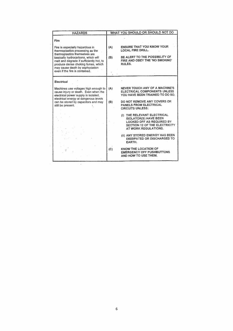
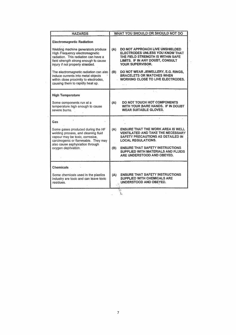
HF WELDING HAZARDS The following paragraphs give warnings about the potential hazards involved when operating, setting or maintaining HF welding equipment. These warnings cannot be comprehensive enough to cover every potential hazard in every plastics factory. Always ensure that local safety rules are understood and obeyed. Personnel responsible for First Aid must be able to provide treatment for all potential injuries including RF burns. One hazard that requires special emphasis is that encountered with guillotines. These machines are installed throughout the stationery sector of the plastics industry and can cause serious injuries if misured or are poorly maintained. They are covered by an Approved Code Of Practice (ACOP) which requires the following checks on their electronic eye guards:
(a) Daily Operation must be checked by maintenance personnel. (b) 6-monthly A speed check must be carried out by an approved engineer and a certificate issued.
6
7
8
1. INTRODUCTION This section introduces HF welding and the products made, briefly describes the history of HF welding and also describes the information of the Federation of High Frequency Welders.
1.1 WHAT IS HIGH FREQUENCY WELDING? High Frequency welding is the process of fusing materials together by applying high frequency energy to the area to be joined. The energy produces localised heating of the materials, causing them to soften and melt, thus allowing their molecules to intermingle. After a period of cooling, the materials become joined together at the point of the weld. The resulting weld can be as strong as the original workpiece materials. The most widely used material in High Frequency (HF) welding is Polyvinyl Chloride (PVC) sometimes know as vinyl. It is important to note that not all thin, flexible thermoplastics can be HF welded; the suitability of a plastic for HF welding is determined by its molecular construction. For example, polyethylene sheeting is not suitable whereas nylon 66 although difficult to tear seal can be welded. As with any form of welding, the materials must be heated to a high enough temperature to cause them to fuse with each other. In HF welding, the workpieces are also pressed together to help them fuse. There are two main types of HF Welding:
(a) Plain Welding The welding of two or more thicknesses of material, the welding tool can be engraved to give the welded area a decorative appearance.
(b) Tear-Seal Welding
The dual process of simultaneously welding and cutting a material. This is achieved by incorporating a cutting edge adjacent to the welding edge. This compressed the hot PVC enough to allow the scrap material to be torn off. This technique can also be used to provide‘cut outs’ to enable plastic packaging to be hung on sale displays.
The welding process can incorporate ‘blind’ embossing which places lettering, logos or decorative effects onto the welded items. Another technique used is Appliqué Welding where a piece of material is cut out and welded to the surface of another to provide an ornamental effect.
1.2 TYPICAL END PRODUCTS A wide range of products can be manufactured using HF welding. The range of products is increasing as a new applications are discovered. A few examples are listed below: Stationery Book covers, labels, binders, notebooks, stationery wallets, zip bags and office files. Inflatable Items Advertising novelties, beach balls, toys, air/water beds, rafts, and life jackets. Household Items Chair upholstery, headboards, quilting and table mats. Everyday Items Badges, car door panels, signs, tents, umbrellas, chequebook covers. Large Items Tarpaulins, tents and marquees, pool liners and lorry covers. Medical Items Colostomy bags and blood bags. In order to produce these different items as efficiently and economically as possible, the range of HF welding equipment available is expanding.
9
1.3 HISTORY The origin of HF welding is closery associated with the early days of radio and radar when the heating effect of radio waves was discovered. Since then, the development of thermoplastic materials and HF welding have progressed hand-in-hand, enabling new materials and the machines necessary to weld them to be manufactured. The history of HF welding since its origin is given in an article written by Cliff Bennion, an Honorary member of the Federation of High Frequency Welders. The text of the article is reproduced in Appendix A of this manual.
1.4 THE FEDERATION OF HIGH FREQUENCY WELDER In late 1986, a group of HF welders arranged a meeting to discuss forming an organisation to represent the interests of all HF welders in the UK. After much discussion they decided to contact the several hundred companies that make up the HF welding industry in the UK. As a result of this initial meeting, another meeting was held in mid-1987, when a Management Committee was elected, and the Federation of High Frequency Welders (FHFW) was formed. Within a year of the formation of the FHFW, 130 companies had joined the Federation. In 1988, the FHFW became a company limited by guarantee. Since its formation in 1987, the Federation has gone from strength, now having members world-wide. The FHFW is dedicated to the promotion and well-being of manufactures, and their suppliers in the High Frequency Welding industry. Based in Ashburton, Devon, the Federation is non-profit making and non-political and exists solely for the benefit of its members. The Federation offers a wide range of services and benefits to its membership including technical, commercial and legal advice. The High Frequency Welder, a glossy bi-monthly magazine produced by the Federation, is the mouthpiece of the industry and provides the forum for discussion within the industry. The magazine reaches a wide readership, mainly within the U.K., but also throughout the E.C. and in many other countries across the word. 2. THE HF WELDING PROCESS This section describes the HF welding process in simple terms. The fusing of the materials in the area of the weld is explained, followed by the methods used to practically perform the weld. 2.1 WHY USE HIGH FREQUENCY POWER? Plastic materials can be welded by applying heat externally, e.g. by using a tool similar to a domestic iron or a hot air gun. Generally, this form of welding is restricted to very thin materials, such as Polyolefins. Bulky items, such as some tarpaulins which are too large to be accommodated in an HF welding machine, are sometimes welded by using a hot air gun. This type of welding is difficult and can only be successfully carried out by experienced operators. Other types of plastc materials can be welded by direct heat alone, but the process is impractical. If direct heat alone is applied to PVC, it can degrade the outer surface, which may overheat before the inner surfaces are hot enough to weld together. The High Frequency welding technique overcomes the problems associated with the application of direct heat alone, and enables plastic materials to be welded under controlled conditions. By applying a controlled amount of High Frequency (HF) power, it is possible to heat the materials so that the zone of resulting higher temperatures includes the surfaces to be welded together. Heating the contact boundaries using this method forms a strong weld without damaging the outer surfaces of the materials.
10
High frequency welding depends on a process of converting electrical energy into heat energy within the workpieces to raise their temperatures enough to melt, and therefore fuse them. Materials that do not conduct electricity such as air, oil, and PVC are sometimes called dielectrics. In HF Welding, the plastic dielectric materials to be welded are sandwhiched between two conductors, called electrodes. When HF power is passed between these electrodes, an alternating electric field is generated through the dielectric materials. The switching electric field agitates the dielectric material’s molecules causing it to heat up. The effect of heating is at a maximum at a point half way between the electrodes, at the junction of the two dielectric materials due to the heat-sink effect of the colder electrodes in contact with the outer surfaces. Once the dielectric materials have fused, the HF power is switched off and the workpieces are allowed to cool. The frequency used by most HF welding machines is 27.12MHz, this means the electric field is cycled 27.12 million times per second. As each cycle comprises a positive half cycle and a negative half cycle, the electric field is applied at twice the frequency, i.e. 54.24 million times per second.
2.2 PRACTICAL HF WELDING In HF Welding, the lower electrode is usually a wide flat metal plate generally called a platen. A large welding machine may also be provided with a moving upper platen which carries tooling shaped to create the required weld pattern in the workpieces. The upper platen is connected to the HF supply and moves up and down during the welding process enabling the tooling to be brought into contact with the workpieces. The force with which the upper platen presses against the workpieces can be applied by springs, weights or for ‘heavy’ welding by electric motor, compressed air on hydraulics. The lower platen is connected to electrical earth, and is usually fixed in position. This platen must be strong enough to withstand the pressure applied by the upper platen.
2.3 BARRIER MATERIALS A barrier, or buffer, material is a thin sheet of dielectric that is placed between the work material and the welding machine’s lower platen. This can help the welding process in several ways, dependent on the properties of the barrier material. Any material used as a barrier must be able to be repeatedly used in the electric field without being affected. Barrier material has two distinct purposes. Firstly it prevents the cutting edge of a tear-seal electrode touching the bottom platen and thereby causing an arc, and secondly, it provides a thermal barrier to prevent the bottom platen absorbing heat from the workpiece. A barrier sheet will usually be between 0.15mm and 0.5mm in thickness, this is enough to decrease the heat flow, and increase the weld temperature thus allowing a larger area of weld to be made with a given amount of HF power. Too much thermal insulation will cause the workpiece to melt near to its outer surfaces, rather than at the interface of the two pieces. The dielectric strength of a barrier bmaterial is measured in kilovolts per millimetre. This measurement gives an indication of the voltage which can be applied across the material before it breaks down and loosers its insulation properties. The most popular buffer materials are composite materials, e.g. waxed paper or varnished cotton. These flexible materials can be easily stored and cut. Some examples of commonly used barrier materials are: Elephantide Supplied in various thicknesses and in rolls 48 inches (1219mm) wide. Also available with thin film
Melinex laminated to its surface which gives a good shine on the reverse side of the weld line and the PVC has a tendency to stick lightly alone the weld lines.
11
Silicone Rubber Flexible rubber sheeting, available in rolls of several thicknesses. Works up to 160°C, non-stick, not affected by the HF frequencies used by welding machines. It is often used in car door panel production
Paxolin Rigid sheeting of thermosetting resin impregnated paper, available in squares of different
thicknesses and areas. Usually, the lighter the colour of the material, the better the quality. Its disadvantage is that it may split or crack when cut.
Melinex This is a tough material that will resist the wear and tear from the cutting edges of any welding
tools. It can also be used in combination with another material that provides additional electrical and thermal insulation.
2.4 SETTING MACHINE CONTROLS The welding process is generally quit tolerant of machine settings, and satisfactory welds can be obtained even if one or more of the settings is not at its optimum value. The tolerance of the settings is dependent on the material being welded, PVC is relatively tolerant but other materials, for example medical films, are not. However, with optimum settings a satisfactory weld will be obtained over a wide range of conditions which may occur in a typical operating period. For example, the temperature of the upper platen will increase as work progressed and the workpiece material may vary in quality, even if from the same batch. Settings for a specific job cannot necessarily be repeated at a later date. The composition and thickness of the workpiece material can vary, the components in the HF generator age and affect the level of the output power, and the mechanical components of the welding machine wear. Also the ambient temperature will vary from day to day and the incoming with sophisticated control systems. Successful machine setting rilies on experience and the careful monitoring of the completed work. The following controls need to be correctly adjusted to obtain the optimum weld: (a) Tool Pressure (b) Press Stroke Adjustment (c) Depth of Sink Control (d) HF Power Output (e) Welding Time (f) Cooling Time (g) Plain temperature
2.4.1 Pressure This is the force applied to push the tooling into the workpiece. This adjustment is often overlooked, as the welding process is quite tolerant of force applied to the tools. Faster wels can be obtained by using greater pressures. Pressures as low as 1kg/cm can be used to obtain a weld. For plain welding, a depth of sink control must be used. The pressure applied should be enough to allow the tools to penetrate into the workpiece when hot. Care must be taken to avoid the use of excessive force, especially for cut-and-weld tools.
2.4.2 Press Stroke Adjustment The press stroke is the vertical distance the upper platen or toolholder can travel, its adjustment depends mainly on the type of welding process. In a process where visibility of the workpiece is important, the upper platen must be allowed
12
to travel clear of the operator’s line of sight. In automatic or high throughput processes, the amount of travel must be limited to shorten the length of each process cycle.
2.4.3 Depth of Sink Control The depth of sink control is most important when not using a tear seal tool. The sink control limits how far the tooling will sink into the PVC. Adjustment of this control will assist in obtaining the optimum weld strength.
2.4.4 HF Power Control The power supplied from the HF generator depends upon, among other factors, the tuning of an electrical circuit. The tuning of that electrical circuit is usually achieved by means of a variable capacitor. Although this controls the power output, it is not possible to calibrate it directly because of the other variables. This is analogous to the accelerator in a car, it cannot be calibrated, because the speed depends on the road conditions, selected gear etc. Great care should be taken to prevent too much power being used, as this will result in damage to the workpiece and tools. It is best to start with the adjuster set to zero, and steadily increase the power until the required power is achieved. It is better to use a little more time and less power, than the other way around. When the material is heated, the electrodes will sink into the workpiece. This will cause the power drawn from the generator to increase. When the material reaches melting point, an electrical change occurs which causes the power to reduce. This falling back is often used to delect the completion of a weld.
2.4.5 Welding Time This is the length of time that the HF power is applied to, and creates heat in the workpiece. A steady or falling power meter reading is an indication that the temperature within the workpiece is no longer increasing. The power should be terminated soon after this state is achieved. This is very important, as over-heating can cause damage to the workpiece. Often, the effects of over-heating are not obvious, but they can be very serious. Not only the weld area is being heated, the rest of the workpiece is also being heated, which causes the material alongside the weld to weaken. One way to check for over-heating is to inspect the area around the tool impression. If it “shines” or the finish has degraded, then the workpiece has probably been overheated.
2.4.6 Cooling Time This is the length of time between the end of the welding time and the lifting of the welding tool from the workpiece. When the HF power has been shut off, the cooling process will be rapid, as long as the metallic tools are in contact with the workpiece. During the repetitive welding and cooling, the tools and surroundings become quite hot. Because of this, later pieces to be welded have a lesser rate of cooling into the warmer tools and worktable or loading tray. Therefore cooling time may have to be increased to compensate. The pressure of the tools should be maintained until the temperature of the workpiece has fallen well below the fusion temperature. Typically, the cooling time should be approximately 20% the length of the weld time.
2.4.7 Platen Temperature Some welding machines, usually those used for welding thick materials or rigid PVC, have heated platens. By using a heated platen, the heat loss from the workpiece material is reduced, enabling a larger area to be welded for a given HF power rating. Also, because the platen temperature is high relative to the ambient temperature and is thermostatically controlled, fluctuations in ambient temperature can be virtually ignored.
13
An uncontrolled platen temperature will rise as the production shift progresses due to the heating effect of the Hf power being transmitted into the platen, and lead to modifications required to the power setting as the day progressed. A controlled platen temperature should give a static power setting as the day progressed. A controlled platen temperature should give a plastic power setting and consistent weld throughout the production shift. For rigid materials such as blister packaging applications, a heated platen is essential so that the tool ‘beds town’ into the material and closes any air gaps which could start an arc.
3. MACHINERY 3.1 GENERAL There is a wide range of machinery used in the manufacture of plastic products. Generally, the machines are in the following groups: (a) Preparation of materials for HF welding, eg cutters, slitters, panellers, guillotines etc. (b) HF welding (c) Assembly and finishing of the final product, eg tear sealing strippers, riveters, printers, press stud sewers etc. Machines other than HF welding machines are outside of the scoope of this handbook, but it should be remembered that many machines can be used in the manufacture of goods containing welded plastic components.
3.2 HF WELDING MACHINES HF welding machine applications are very diverse. Machines can be used to produce a wide range of goods from small items such as key fobs to much larger items such as car components. To produce this wide range, many different types of HF welding machines exist. It is not only the size of the components produced which affects the machine required to produce it, but also the type of component. For example a simple product may only require to workpieces to be welded. Other components will require assembling before welding, and finishing afterwards. These considerations affect the design of the machine.
3.3 MAJOR COMPONENTS All HF welding machines incorporate four major basic components as follows: (a) HF power generator. (b) Press. (c) Workpiece handling mechanism. (d) Control system.
3.3.1 HF Power Generator The HF power Generator produces high frequency electricity required to perform the welding process. In small machines, the generator is usually integrated into the casing of the machine, and in larger machines the generator is a ‘standalone’ piece of equipment located adjacent to the machine. The frequency of the output is usually 27.12 MHz maintained to within + 0.6%. The maximum output power level varies from machine to machine, depending on the type of material to be welded, the thickness of the material and the area of the required weld. For any machine, the maximum power output, measured
14
in Watts or kilowatts in know as the rating of the machine which is one of the most important items quoted in machine specifications. The ratings of machines vary from a few hundred Watts to tens of kilowatts. The output power level can be adjusted to suit the conditions required for the weld. A visual indication of the output power is given by a panel meter, usually of the moving-coil type. By observing this meter, it is possible to monitor the progress of the weld. The output stage of the generator incorporates thermionic valves. Although semiconductor devices could provide the require output power in the low power ranges, valves are far more robust, able to whitstand the sometimes erratic loading caused by the welding process. Valves do gradually deteriorate with age and use, and need to be renewed after long periods of use (tipically a few years).
3.3.2 Press A press provides the means of pressing welding tools against work materials whilst applying HF power, plus the subsequent essential period of cooling time. Pedal operated welding machine usually employ downstroking presses with versatile toolholding arrangements to press tools down on to the work material which is resting on a robust metal worktable, often called a platen. Larger machines may provide an ‘upper’ platen to carry large tools which take advantage of the strength of that platen to prevent distortion when they are pressed onto the work. There are two main types of press, a ‘C’ shaped press and a ‘bridge’ shaped press. C type press – The few view of the press resembles the letter ‘C’. This metod of construction requires the use of relatively heavy cast components. Because the body of the press is located at the rear of the machine, accessibility to the work area between the platens is unobstructed. The RF power is fed to the upper electrode from the centre of the press. The type of press is used in machines from small foot-operated types to power presses capable of exerting several tonnes of force. Bridge Press – The press is constructed using supports at both sides of the work area, with the upper platen operating from the ‘span’ between the supports. This method of construction provides a rigid and symmetrical press using relatively light weight components. The accessibility of this type of press is limited to the front and rear between the side supports. The RF power can be fed from both sides of the ‘bridge’ or centrally from the top to give a more even distribution of the RF field at the tooling.
3.3.3 Control System The purpose of the control system is to ensure that the machine can be started, operated and stopper efficiently and safely. Control system range from simple mechanical and electrical controls on small machines to full machine and process automation on large complex machines. Functions which can be controlled are: a) Starting the machine in conjunction with any necessary ‘safety’ interlocks. b) Monitoring an adjusting process parameters: (i) Stroke and pressure of the welding press. (ii) The HF power input to the workpiece which is the heating phase of the welding cycle. (iii) The timing of the heating and cooling phases. (iv) The operation of the handling system. c) Stopping the machine in the event of an emergency or a potentially hazardous situation, eg an
operator attempting to use the machine without a safety guard in place. d) Monitoring the HF power to detect arcing and turning the generator off to limit the affects of
arcing.
15
e) Protecting electric motors and other electrical components by tripping them out on the
detection of an electrical overload. Modern machine incorporate sophisticated control system which use advanced software controlled devices such as microprocessors and programmable logic controllers (PLCs). These devices enable control functions to be implemented accurately with good repeatability. 3.3.4 Handling Mechanisms
The handling mechanisms feds the workpieces to the press, then positions them under the press for welding. Once welded, the workpieces are removed. There are several types of handling mechanism:
Manual On small machines, eg pedal operated, the workpieces are fed to the press, positioned for
welding and removed by hand. Linear A conveyor belt system feeds the workpiece materials to the presses. The conveyor belt stops
to position the workpieces correctly for welding (this is know as ‘indexing’) then removes them from the press. When a linear indexing machine is correctly adjusted, the operator only needs the monitor the weld quality, ensure that there is a sufficient supply of workpiece materials, and remove the finished products.
Rotary A circular table rotates positioning workpieces correctly. This allows operators, at a number of
workstations, to assemble the workpieces before welding and remove welded workpieces. The number of workstations of a rotary tabledepends on the complexity of the workpieces, and the number of finishing processes.
Rail When workpieces are too large to be accommodated in a fixed machine, eg tarpaulins,
swimming pool liners etc, a rail handling mechanism is used. In this type of machine, the workpieces are held stationary and the welding press is moved along on a rail to perform repeated welds.
In addition to the handling mechanisms listed above, some machines, eg linear and rotary can be fitted with ‘Placer’ assemblies. These assemblies use pneumatically controlled suction cups to automatically pick up a component from a stack then place it on the work table ready for welding. Typical components than can be handled by Placers are grey board or PVC workpieces.
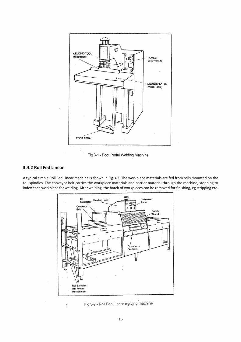
3.4 TYPES OF MACHINE 3.4.1 Foot Pedal A typical Foot Pedal machine is shown Fig 3-1. The workpiece is placed on the lower platen which forms the work plate. The welding tool is brought into contact with the workpiece by pressing the foot pedal.
16
3.4.2 Roll Fed Linear A typical simple Roll Fed Linear machine is shown in Fig 3-2. The workpiece materials are fed from rolls mounted on the roll spindles. The conveyor belt carries the workpiece materials and barrier material through the machine, stopping to index each workpiece for welding. After welding, the batch of workpieces can be removed for finishing, eg stripping etc.
17
Specialised versions of the roll fed linear machine can be far more complex. For example, a machine to produce stationery binders can perform the following operations:
(a) Feed the upper and lower materials from rolls, automatically adjusting the roll tension. (b) Place the grey board between the two workpiece layers. (c) Place a transparent PVC cover on top of the assembled workpieces. (d) Weld the assembled components (e) Place a pocket on the spine of the binder, then weld into the spine. (f) Strip the welded binder from the surplus material. (g) Stack the stripped binders onto a conveyor belt.
This type of automated machine is expensive and setting it up for a production run takes typically one to two hours. Therefore for economic operation, the machine would only be used for production batches of 1000 or more binders.
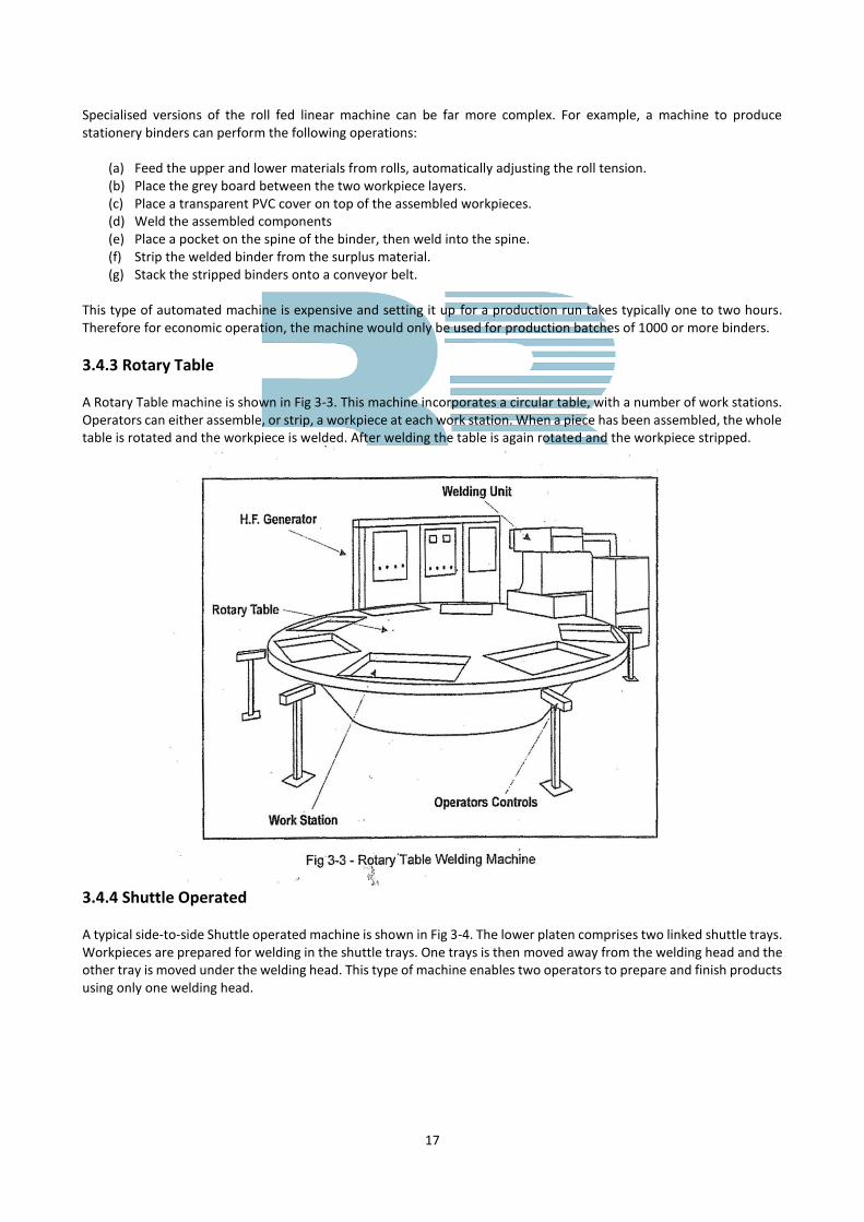
3.4.3 Rotary Table A Rotary Table machine is shown in Fig 3-3. This machine incorporates a circular table, with a number of work stations. Operators can either assemble, or strip, a workpiece at each work station. When a piece has been assembled, the whole table is rotated and the workpiece is welded. After welding the table is again rotated and the workpiece stripped.
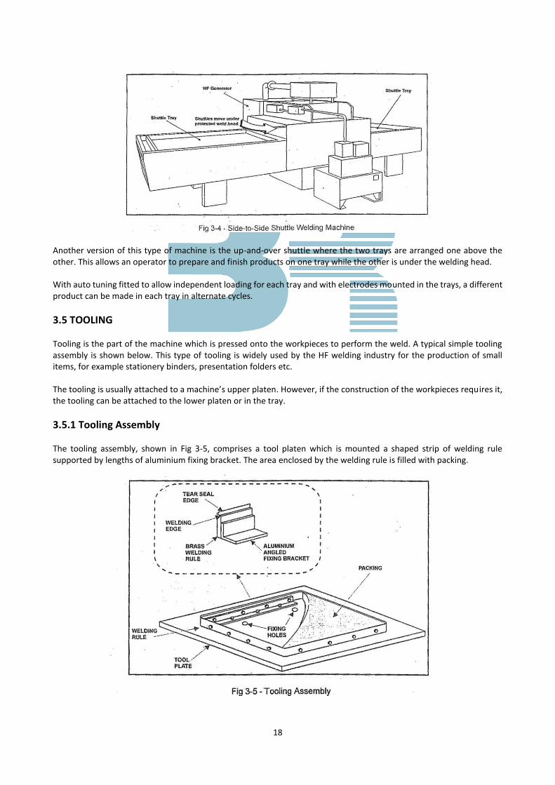
3.4.4 Shuttle Operated A typical side-to-side Shuttle operated machine is shown in Fig 3-4. The lower platen comprises two linked shuttle trays. Workpieces are prepared for welding in the shuttle trays. One trays is then moved away from the welding head and the other tray is moved under the welding head. This type of machine enables two operators to prepare and finish products using only one welding head.
18
Another version of this type of machine is the up-and-over shuttle where the two trays are arranged one above the other. This allows an operator to prepare and finish products on one tray while the other is under the welding head. With auto tuning fitted to allow independent loading for each tray and with electrodes mounted in the trays, a different product can be made in each tray in alternate cycles.
3.5 TOOLING Tooling is the part of the machine which is pressed onto the workpieces to perform the weld. A typical simple tooling assembly is shown below. This type of tooling is widely used by the HF welding industry for the production of small items, for example stationery binders, presentation folders etc. The tooling is usually attached to a machine’s upper platen. However, if the construction of the workpieces requires it, the tooling can be attached to the lower platen or in the tray.
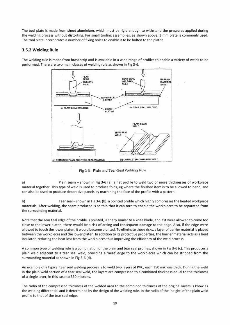
3.5.1 Tooling Assembly The tooling assembly, shown in Fig 3-5, comprises a tool platen which is mounted a shaped strip of welding rule supported by lengths of aluminium fixing bracket. The area enclosed by the welding rule is filled with packing.
19
The tool plate is made from sheet aluminium, which must be rigid enough to withstand the pressures applied during the welding process without distorting. For small tooling assemblies, as shown above, 3 mm plate is commonly used. The tool plate incorporates a number of fixing holes to enable it to be bolted to the platen.
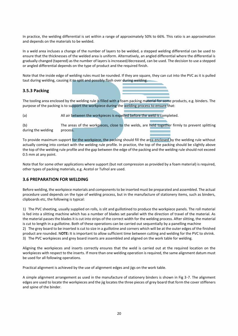
3.5.2 Welding Rule The welding rule is made from brass strip and is available in a wide range of profiles to enable a variety of welds to be performed. There are two main classes of welding rule as shown in Fig 3-6.
a) Plain seam – shown in Fig 3-6 (a), a flat profile to weld two or more thicknesses of workpiece material together. This type of weld is used to produce folds, eg where the finished item is to be allowed to bend, and can also be used to produce decorative panels by machining the face of the profile with a pattern. b) Tear seal – shown in Fig 3-6 (b). a pointed profile which highly compresses the heated workpiece materials. After welding, the seam produced is so thin that it can torn to enable the workpieces to be separated from the surrounding material. Note that the sear teal edge of the profile is pointed, is sharp similar to a knife blade, and if it were allowed to come too close to the lower platen, there would be a risk of arcing and consequent damage to the edge. Also, if the edge were allowed to touch the lower platen, it would become blunted. To eliminate these risks, a layer of barrier material is placed between the workpieces and the lower platen. In addition to its protective properties, the barrier material acts as a heat insulator, reducing the heat loss from the workpieces thus improving the efficiency of the weld process. A common type of welding rule is a combination of the plain and tear seal profiles, shown in Fig 3-6 (c). This produces a plain weld adjacent to a tear seal weld, providing a ‘neat’ edge to the workpieces which can be stripped from the surrounding material as shown in Fig 3-6 (d). An example of a typical tear seal welding process is to weld two layers of PVC, each 350 microns thick. During the weld in the plain weld section of a tear seal weld, the layers are compressed to a combined thickness equal to the thickness of a single layer, in this case to 350 microns. The radio of the compressed thickness of the welded area to the combined thickness of the original layers is know as the welding differential and is determined by the design of the welding rule. In the radio of the ‘height’ of the plain weld profile to that of the tear seal edge.
20
In practice, the welding differential is set within a range of approximately 50% to 66%. This ratio is an approximation and depends on the materials to be welded. In a weld area incluses a change of the number of layers to be welded, a stepped welding differential can be used to ensure that the thicknesses of the welded area is uniform. Alternatively, an angled differential where the differential is gradually changed (tapered) as the number of layers is increased/decreased, can be used. The decision to use a stepped or angled differential depends on the type of product and the required finish. Note that the inside edge of welding rules must be rounded. If they are square, they can cut into the PVC as it is pulled taut during welding, causing it to split and possibly flash over during welding.
3.5.3 Packing The tooling area enclosed by the welding rule is filled with a foam packing material for some products, e.g. binders. The purpose of the packing is to support the workpiece during the welding process to ensure that: (a) All air between the workpieces is expelled before the weld is completed. (b) The areas of the workpieces, close to the welds, are held together firmly to prevent splitting during the welding process. To provide maximum support for the workpiece, the packing should fill the area enclosed by the welding rule without actually coming into contact with the welding rule profile. In practice, the top of the packing should be slightly above the top of the welding rule profile and the gap between the edge of the packing and the welding rule should not exceed 0.5 mm at any point. Note that for some other applications where support (but not compression as provided by a foam material) is required, other types of packing materials, e.g. Acetol or Tufnol are used.
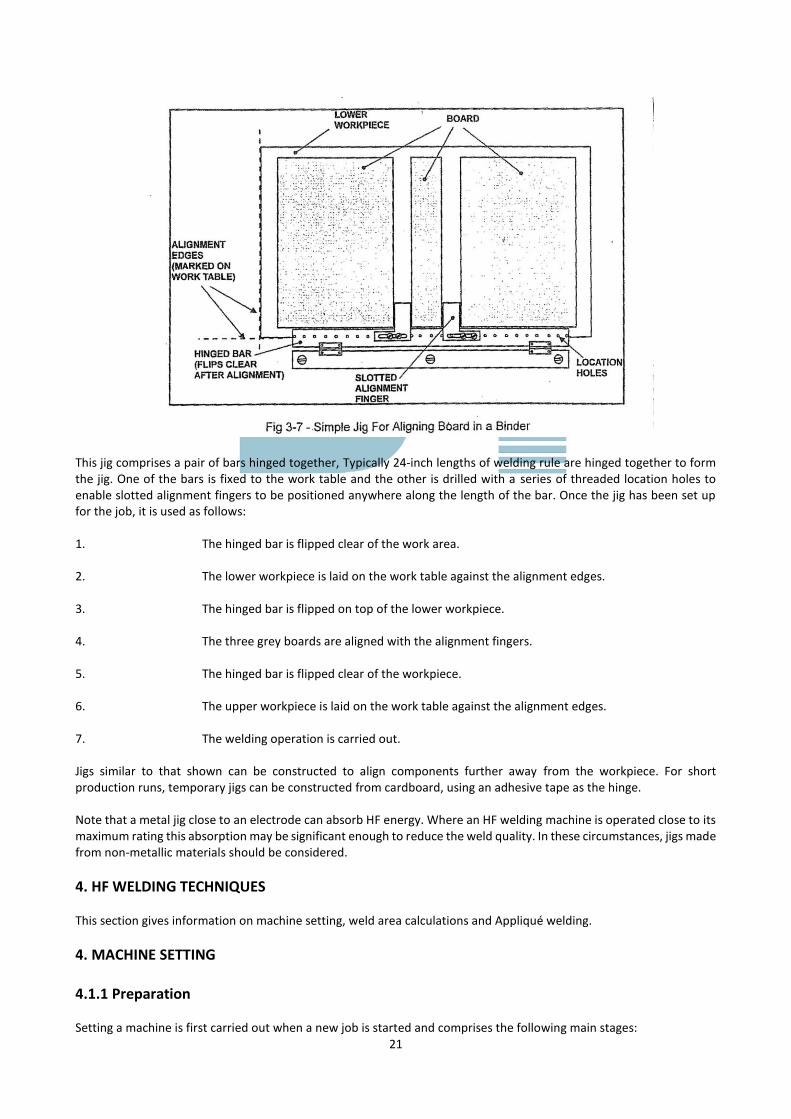
3.6 PREPARATION FOR WELDING Before welding, the workpiece materials and components to be inserted must be preparated and assembled. The actual procedure used depends on the type of welding process, but in the manufacture of stationery items, such as binders, clipboards etc, the following is typical: 1) The PVC sheeting, usually supplied on rolls, is slit and guillotined to produce the workpiece panels. The roll material is fed into a slitting machine which has a number of blades set parallel with the direction of travel of the material. As the material passes the blades it is cut into strips of the correct width for the welding process. After slitting, the material is cut to length in a guillotine. Both of these operations can be carried out sequentially by a panelling machine 2) The grey board to be inserted is cut to size in a guillotine and corners which will be at the outer edges of the finished product are rounded. NOTE: It is important to allow sufficient time between cutting and welding for the PVC to shrink. 3) The PVC workpieces and grey board inserts are assembled and aligned on the work table for welding. Aligning the workpieces and inserts correctly ensures that the weld is carried out at the required location on the workpieces with respect to the inserts. If more than one welding operation is required, the same alignment datum must be used for all following operations. Practical alignment is achieved by the use of alignment edges and jigs on the work table. A simple alignment arrangement as used in the manufacture of stationery binders is shown in Fig 3-7. The alignment edges are used to locate the workpieces and the jig locates the three pieces of grey board that form the cover stiffeners and spine of the binder.
21
This jig comprises a pair of bars hinged together, Typically 24-inch lengths of welding rule are hinged together to form the jig. One of the bars is fixed to the work table and the other is drilled with a series of threaded location holes to enable slotted alignment fingers to be positioned anywhere along the length of the bar. Once the jig has been set up for the job, it is used as follows: 1. The hinged bar is flipped clear of the work area. 2. The lower workpiece is laid on the work table against the alignment edges. 3. The hinged bar is flipped on top of the lower workpiece. 4. The three grey boards are aligned with the alignment fingers. 5. The hinged bar is flipped clear of the workpiece. 6. The upper workpiece is laid on the work table against the alignment edges. 7. The welding operation is carried out. Jigs similar to that shown can be constructed to align components further away from the workpiece. For short production runs, temporary jigs can be constructed from cardboard, using an adhesive tape as the hinge. Note that a metal jig close to an electrode can absorb HF energy. Where an HF welding machine is operated close to its maximum rating this absorption may be significant enough to reduce the weld quality. In these circumstances, jigs made from non-metallic materials should be considered.
4. HF WELDING TECHNIQUES This section gives information on machine setting, weld area calculations and Appliqué welding.
4. MACHINE SETTING 4.1.1 Preparation Setting a machine is first carried out when a new job is started and comprises the following main stages:
22
1. Selecting and fitting the tooling plate to the upper electrode. 2. Selecting and fitting the appropriate barrier material. 3. For linear indexing machines, feeding the workpiece webs from the reels through the machine. 4. Ensuring that there is sufficient supply of materials and other required components to hand. 5. Setting the machine controls to obtain the optimum weld. Once the machine is in use, the settings are checked periodically, e.g. hourly or once a shift. During operation, if the quality of the welded products become unsatisfactory the cause should be investigated and the machine sdjusted/repaired accordingly.
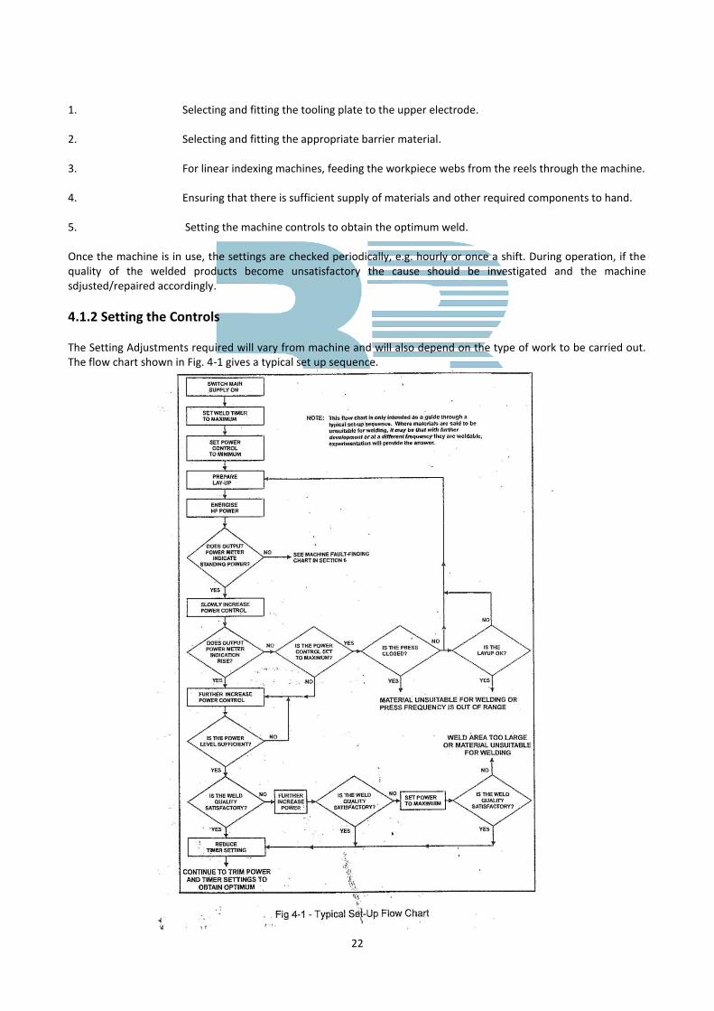
4.1.2 Setting the Controls The Setting Adjustments required will vary from machine and will also depend on the type of work to be carried out. The flow chart shown in Fig. 4-1 gives a typical set up sequence.
23
4.2 WELD AREA CALCULATIONS The HF power required to weld a given area depends upon a number of factors. In this sub-section, these factors will be described briefly and the relationship between HF power and weld area will be discussed. The formulae given should be regarded as a ‘rule of thumb’ from which to start setting the HF power level. 4.2.1 HF Genetator Considerations HF generators have a standing (quiescent) current, or base energy consumption which is required to supply the electrical circuits in readiness for welding. The base energy consumption is approximately 5% of the rated energy output and is taken from the incoming electrical supply during the whole period the welding machine circuits are energised. The remaining available power (i.e. that above the base energy consumption) provides a weld area that is approximately proportional to the generator output. For example, a 6kW generator is capable of welding an area approximately twice that of a 3kW generator. The efficiency of an HF generator is approximately 60%. This means that of the input power, 40% (including the base energy consumption) is dissipated as heat in the electrical circuits leaving 60% to be converted into HF power. Therefore a machine with a rated output of 6kW will require a supply of 10kW when operating at its maximum power output. The maximum power output is only achieved when the electrode sinks into the workpiece materials. Thus during the period when the HF power is applied for the weld, the average power supplied to the electrode is considerably less than the maximum power output. Also, when taking the cooling time and time for unloading and loading components into account, the overall power consumption is a small fraction of that taken when the output power is at its maximum.
4.2.2 Basic Calculation of Required Power The relationship between a given workpiece area and the HF power necessary to weld it has been estabilished as typically 25 cm per Kilowatt. This is an approximation based on welding two thicknesses of 0.010” (0.254 mm) PVC with a relatively wide plain electrode. In practice, depending on the factors discussed later, the welded area achieved per Kilowatt could be between 10 and 30 cm or 2 to 5 inches. To achieve a more realistic estimation of the weld area per Kilowatt, the following factors which affect the actual power requirement must be taken into consideration:
(a) Area of Weld Approximately directly proportional to required power.
(b) Type of Material The higher the loss factor of the material, the lower the power requirement.
(c) Thickness of Material
The thicker the PVC, the lower the power requirement due to reduced heat losses.
(d) Edge Factor This is the total edge length of the welding electrode. A long narrow electrode requires more power than a wide electrode of the same area.
(e) Length of Tear and Seal Edge (if any) Tear seal edges require more power than plain welds.
(f) Thickness and Type Of Barrier Material (g) Less power is normally required when barrier materials are used but increased electrode voltage
will be necessary.
24
(h) Type and DesignOf Electrode The heat conductivity of the electrode, whether it is temperature controlled and whether it
incorporates components which absorb HF power.
(a) Required Welding Time The shorter the required time, the larger the required power, but limiting factors also apply to avoid flashing at the electrode.
Consider the example quoted earlier of two thicknesses of 0.010” (0.254 mm) PVC with a relatively wide plain electrode requiring 1kW to weld 25 cm. For the same weld area using a tear seal weld on 0.005” (0.127 mm) PVC with a low vinyl content, only 0.5 kW would be required.
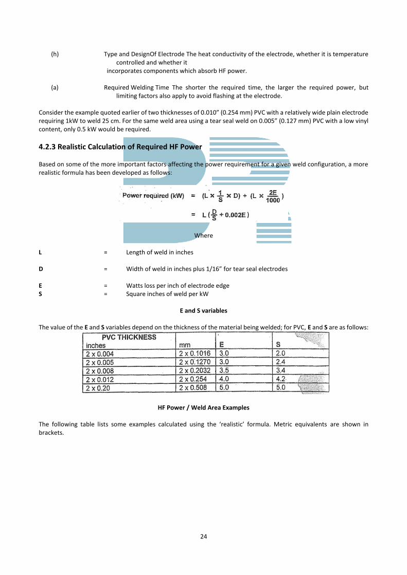
4.2.3 Realistic Calculation of Required HF Power Based on some of the more important factors affecting the power requirement for a given weld configuration, a more realistic formula has been developed as follows:
Where
L = Length of weld in inches D = Width of weld in inches plus 1/16” for tear seal electrodes E = Watts loss per inch of electrode edge S = Square inches of weld per kW
E and S variables
The value of the E and S variables depend on the thickness of the material being welded; for PVC, E and S are as follows:
HF Power / Weld Area Examples
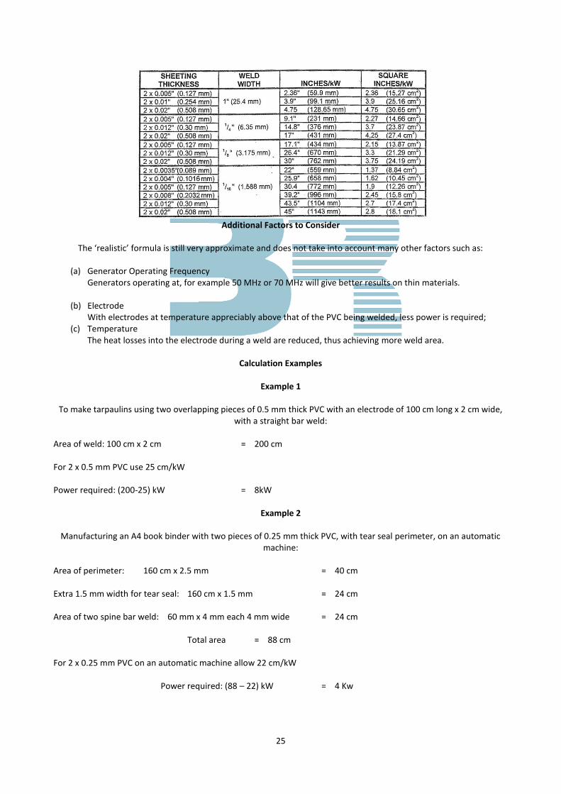
The following table lists some examples calculated using the ‘realistic’ formula. Metric equivalents are shown in brackets.
25
Additional Factors to Consider
The ‘realistic’ formula is still very approximate and does not take into account many other factors such as:
(a) Generator Operating Frequency
Generators operating at, for example 50 MHz or 70 MHz will give better results on thin materials.
(b) Electrode With electrodes at temperature appreciably above that of the PVC being welded, less power is required;
(c) Temperature The heat losses into the electrode during a weld are reduced, thus achieving more weld area.
Calculation Examples
Example 1
To make tarpaulins using two overlapping pieces of 0.5 mm thick PVC with an electrode of 100 cm long x 2 cm wide,
with a straight bar weld:
Area of weld: 100 cm x 2 cm = 200 cm For 2 x 0.5 mm PVC use 25 cm/kW Power required: (200-25) kW = 8kW
Example 2
Manufacturing an A4 book binder with two pieces of 0.25 mm thick PVC, with tear seal perimeter, on an automatic machine:
Area of perimeter: 160 cm x 2.5 mm = 40 cm Extra 1.5 mm width for tear seal: 160 cm x 1.5 mm = 24 cm Area of two spine bar weld: 60 mm x 4 mm each 4 mm wide = 24 cm Total area = 88 cm For 2 x 0.25 mm PVC on an automatic machine allow 22 cm/kW Power required: (88 – 22) kW = 4 Kw
26
4.3 APPLIQUE’ WELDING Appliqué decoration is an age-old method of ornamentation whereby one piece of material is cut out and attached to the surface of another. It might be found on a shield or a suit of armour, but more often as a decorative fabric stitched to another woven material. Using PVC sheeting a decorative material permits HF bonding as a method of attachment to woven fabrics by mechanical bonding of melted PVC pushed between the threads or directly onto another PVC sheet. This attachment technique can be plain welding and it is easy to see the attraction of the next logical step, emulating tear-seal welding, which is to arrange for surplus PVC to be stripped away all around the tool impression. A stripping tear may be found to be more easily started from a scissors cut into the surplus material toward the impressed profile, with the surplus PVC pulled horizontally over the impressed surface rather than directly away from the work piece.
4.3.1 Cost Very impressive examples of appliqué welding have been produced, even including several colours of decorative PVC in the same impression, which show just what is possible with skilfully applied technique. Good results cannot be obtained with inappropriate technique anyway, but even when a tool and machine set-up is perfect the most important factor affecting the cost of processing is the time required for hand stripping and finishing when the work has left the welding machine.
4.3.2 Applications The process can produce delicate and fancy decoration, most of its commercial appeal lies in reproducing striking simple artwork requiring little subsequent hand finishing.
4.3.3 Welding Complications arising from fancy shapes and small size mean that most appliqué tools cannot be fabricated using bent brass rule bracketed to a baseplate. Where this construction is used the toolmaking must be meticulously accurate so far as the plane of the welding edges in concerned. For this reason they are best built directly on to thick baseplates rather than thin soleplates which may rely on welding pressure to flatten any residual curvature against their backing plates: this will not happen in appliqué welding where precise depth of sink control is essential. We know that a pointed edge will cut through soft sheeting when sufficient force is applied to it, and in tear-seal welding this is undesirable until the temperature of the work material is raised by HF heating. However, in appliquè welding it seems there can be a distinct advantage when some mechanical cutting occurs before, or very early in the HF heating phase. To get this benefit we need to arrange that: (a) the PVC is soft enough. (b) tool pressure is appropriate.
5. MAINTENANCE The maintenance of HF welding machines falls into two categories, preventive maintenance and faultfinding/repair. Preventive maintenance is the regular cleaning, lubrication, inspection and testing of a machine to keep it in good working order and to prevent breakdowns.
27
Faultfinding and repair are carried out after a machine has broken down or is not operating correctly, to restore the machine to good working order. Preventive maintenance is discussed in this section and fault finding on machines and welds is discussed is Section 6.
5.1 PREVENTIVE MAINTENANCE One aspect of HF welding which is often overlooked, is the regular maintenance of the welding machinery. Regular checks on the machinery can often reveal potential problems well before any damage is caused. This will minimise any downtime cause by damage to the machines, and expensive component renewal. The important rule is “prevention is better than cure!” To ensure that maintenance is not overlooked, it is suggested that a maintenance achedule is drawn up for each machine. The simply lists the maintenance tasks and how often they need to be carried out. For maintenance details of specific machines, read the manufacturer’s manuals supplied with the machine. WARNINGS 1. MAINTENANCE MUST ONLY BE CARRIED OUT BY PERSONNEL QUALIFIED TO DO SO AND WHO ARE AWARE OF THE RISKS INVOLVED. 2. WELDING MACHINES ARE SUPPLIED WITH ELECTRICAL SUPPLIES WHICH CAN BE LETHAL. THEREFORE ANY MAINTENANCE ON ELECTRICAL CIRCUITS MUST ONLY BE CARRIED OUT BY QUALIFIED ELECTRICIANS. 3. DO NOT REMOVE ANY COVERS OR PANELS FROM ELECTRICAL CIRCUITS UNLESS: (A) THE RELEVANT ELECTRICAL ISOLATOR(S) HAVE BEEN LOCKED OFF AS REQUIRED BY SECTION 12 OF THE ELECTRICITY AT WORK REGULATIONS. (B) ANY STORED ENERGY HAS BEEN DISSIPATED OR DISCHARGED TO EARTH.
5.1.1 Cleaning To ensure that a machine continues to operate efficiently and safety it must be kept clean and free from debris. Moving parts can become obstructed, preventing smooth operation of the machine and changing setting adjustments. Electric motors and air intakes to HF generators can become clogged with debris, causing overheating and a potential fire hazard. The work area around machines should also be kept clean and tidy to minimise the risks of personnel slipping, tripping etc.
5.1.2 Lubrication To ensure the smooth running, and long life, of any mechanical system, including welding machines, lubrication is essential. All lubrication should be carried out in accordance with the manufacturers instructions at the specified lubricants. Generally, lubrication should cover the following items:
a) Oil levels in gearboxes, dashpots etc. should be checked weekly. Follow the manufacturer’s instructions regarding oil and filter changes, ensuring that the specified lubricants and components are used.
b) Drive chains and shaft should be lubricated sparingly as recommended by the manufacturer. c) Grease nipples and lubrication points should be lubricated as recommended by the manufacturer.
5.1.3 Inspection For the safe running of any welding machine, there should be regular inspections to check the following:
28
a) All safety guards are functional and fitted correctly. b) All drive chains and drive belts are undamaged, fitted correctly and tensioned correctly.
c) All wiring is routed safely and is undamaged.
d) All electrical connections are secure.
e) All air intakes are free from obstruction.
5.1.4 Testing The welding machines should be regularly tested. These tests should check all aspects of the machine’s operation. For example, they should be checked to ensure that they operate correctly and safety, and at all times conform to any local safety standards including levels of RF emissions.
6. FAULT FINDING
This section gives help for faultfinding on HF welding machines and welds.
The faultfinding on machines is limited to general problems which should be easily solved by trained personnel. For detailed faultfinding refer to the machine manufacturer’s maintenance manuals. 6.1 HF WELDING MACHINES
WARNINGS
1. FAULT FINDING MUST ONLY BE CARRIED OUT BY PERSONNEL QUALIFIED TO DO SO AND WHO ARE AWARE OF THE RISKS INVOLVED.
2. WELDING MACHINES ARE SUPPLIED WITH ELECTRICAL SUPPLIES WHICH CAN BE LETHAL. THEREFORE ANY MAINTENANCE ON ELECTRICAL CIRCUITS MUST ONLY BE CARRIED OUT BY QUALIFIED ELECTRICIANS.
3. DO NOT REMOVE ANY COVERS OR PANELS FROM ELECTRICAL CIRCUITS UNLESS: (A) THE RELEVANT ELECTRICAL ISOLATOR(S) HAVE BEEN LOCKED OFF AS
REQUIRED BY SECTION 12 OF THE ELECTRICITY AT WORK REGULATIONS. (B) ANY STORED ENERGY HAS BEEN DISSIPATED OR DISCHARGED TO EARTH.
The following fault finding charts are for general guidance only, they are not exhaustive and are only intended as a guide through typical fault finding sequences.
29
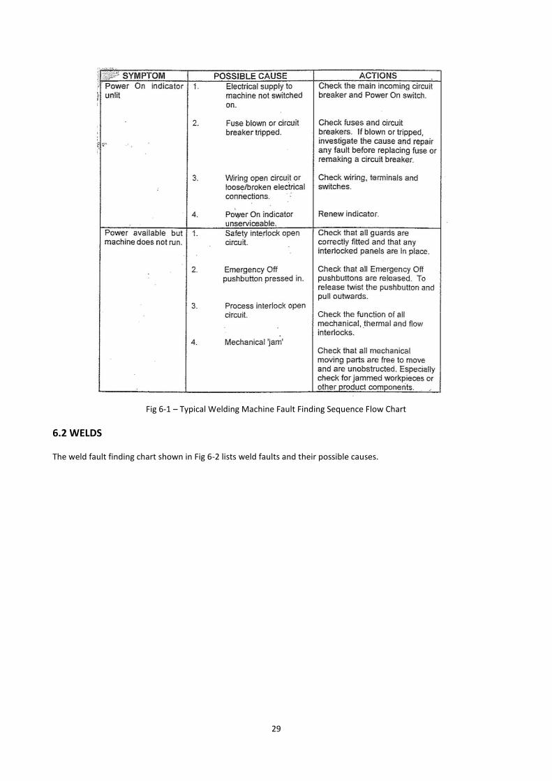
Fig 6-1 – Typical Welding Machine Fault Finding Sequence Flow Chart
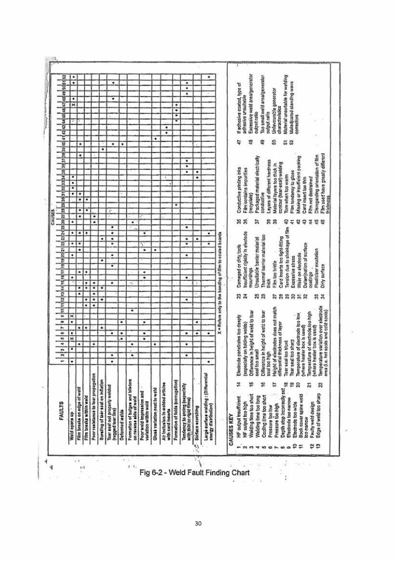
6.2 WELDS The weld fault finding chart shown in Fig 6-2 lists weld faults and their possible causes.
30
31
7. MATERIALS USED IN HF WELDING The following materials are used in HF welding:
(a) Thin sheeting Typical minimum gauge 70 microns, plain, coloured, printed, embossed or unembossed. (b) Thick sheeting Typical maximum single ply gauge 750 microns, but can be laminated to 1.5mm and
above. Plain, coloured, printed, embossed or unembossed. (c) Unsupported Rigid PVC Typical Thickness 150 to 500 micron in roll form or up to 750 micron in panel form. (d) Net reinforced Laminated PVC plies, containing a renforcing net. Ranging from very open net constructions to very close constructions. (e) Coated Fabrics Cotton or synthetic woven fabrics, coated on one or both sides with a PVC composition.
NOTE: See Appendix B for details of Chemical Names, Trade Names and Abbreviations used for materials used in the HF Welding industry. 7.1 NATURE AND PROPERTIES OF PVC
The letters ‘PVC’ stand for polyvinyl chloride. PVC is any material or product made of a PVC composition, i.e. of an intimate mixture of a vinyl chloride polymer or copolymer with various additives, some of which (e.g. plasticisers in a flexible PVC composition) may be present in significant proportion. PVC is a thermoplastic material, i.e. when heated it softens. This allows it to be processed by calendaring, extrusion, injection moulding, vacuum forming, pressing etc.
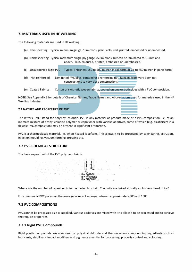
7.2 PVC CHEMICAL STRUCTURE The basic repeat unit of the PVC polymer chain is:
Where n is the number of repeat units in the molecular chain. The units are linked virtually exclusively ‘head to tail’. For commercial PVC polymers the average values of n range between approximately 500 and 1500.
7.3 PVC COMPOSITIONS PVC cannot be processed as it is supplied. Various additives are mixed with it to allow it to be processed and to achieve the require properties.
7.3.1 Rigid PVC Compounds Rigid plastic compounds are composed of polyvinyl chloride and the necessary compounding ingredients such as lubricants, stabilisers, impact modifiers and pigments essential for processing, property control and colouring.
32
7.3.2 Flexible PVC Compounds These are manufactured from polyvinyl chloride and the necessary compounding ingredients such as plasticisers, stabilisers, lubricants, fillers and pigments.
7.3.3 Additives used in the Industry
(a) PVC suspension polymers. (b) Plasticisers – Used in varying quantities for different flexibility. Note that plasticisers not only
make PVC sheeting soft and flexible, but also enable HF welding to be carried out much more easily and with less power required.
(i) Phthalate based, e.g. Di Octyl Phthalate (DOP) and Di-Iso Decyl Phthalate (DIDP). (ii) Low temperature plasticisers to achieve low temperature properties, e.g. Adipates. (iii) Fire retardant plasticisers e.g. Phosphate. (iv) Polymeric Plasticisers – long chain structures to achieve good extraction resistance,
e.g. washing/boiling. (v) Stabilisers – based on metals such as Lead, Barium, Zinc, and Tin. Used to enable PVC
to be processed and to give end use stability. (vi) Lubricants – used in conjunction with stabilisers to enable ease of processing, i.e.
prevents the PVC from sticking to hot metal surfaces. (vii) Fillers – based on calcium carbonate in the main and used to reduce formulation costs. (viii) Pigments – used to colour the compound to give a range of colour and opacity.
(ix) Others – depending on applications:
Impact modifiers – based on MBS/ABS polymers used predominantly in rigid PVC compounds to give strength
and vacuum formability.
UV / Antioxidants – to give good outdoor weathering properties.
Antistatic additives – used to reduce static electricity.
Bactericides / Fungicides – used to reduce fungal attack from micro-organisms.
Fire retardant additives – to boosts the PVC compounds to give fire retardant properties for the various strict
regulations – can be based on antimony, zinc and aluminium compounds.
Process / Matting Agents – can be based on acrylic polymers and other compounds.
7.4 PROPERTIES OF PVC SHEET
The application will determine the necessary additives to be chosen to achieve the necessary specification.
For example, a stationery grade will probably contain:
PVC Polymer, Plasticiser, Stabiliser, lubricant and pigments – a rather basic formulation but the application may
demand the use of a combination of plasticisers:
Di Octyl Phthalate (DOP)
33
Phosphate
Adipate
Together with other additives such as antistatic additives, UV absorbers and bactericides.
The application may also require the careful selection of the metal stabilisers – toxicity i.e. Barium / Zinc based systems
predominately but Calcium / Zinc systems are used in medical, nursery and toy applications.
7.5 FACTORS THAT GOVERN A SATISFACTORY WELDED PRODUCT
Good Lay-Flat and Curvature
This means the way a roll of PVC appears when laid out. If inadequate control has been taken when the PVC was
produced, the sheet may look ‘baggy’ or have cockled edges. The worst case is when the sheet appears to go round
corners, i.e. ‘banana’ effect.
Tear Strength
This means as it says, PVC generally is supplied with good tear strength but this can depend upon the gauge, emboss,
formulation and processing temperatures. Poor tear strength could affect the end product or end process when
welding.
Appearance Defects
Mainly due to inadequate processing techniques including poor choice of PVC additives, packaging defects etc.
Poor Weldability
A number of reasons can cause this:
Excessive use of lubricants in the PVC sheet gives a barrier to HF welding performance and strength.
Contamination either in the sheeting or surface, this could cause arcing at the electrode.
Poor selection of printing inks and lacquer systems causing poor weld strength performance.
Excessive use of fillers within the formulation will cause poor weld strength and will require increased power
settings compared to unfilled products.
The degree of flexibility of a PVC sheet can have an influence on weldability – basically the soften the PVC
sheet, the less power is required to achieve a good weld. However, it may be found necessary to set the
pressure higher on the machine.
Gauge of PVC sheet is an obvious reason for weld variability but can easily be compensated for.
7.6 TYPES OF PVC SHEET AND THEIR USES
Thin Flexible Medical
Nursery
Protective Clothing
Insulation Tape
Self-Adhesive labels
34
Thick Flexible Stationery Products
Automotive
Pool / Pond / Lake lining
Pipe Wrapping
Polished Rigid Packaging Products
Matt Rigid Computer Diskettes
Water Cooling Towers
Video Cassette Cases
Stationery Products
LaminatesBlinds and Awnings
Highweight Tarpaulins
Horticultural Covers
Other Heavy Duty Applications
7.7 THE ROLE OF PLASTICISERS IN FLEXIBLE PVC SHEETING
7.7.1 Introduction
PVC is unusual in many respects when compared with other plastics. It is made from two raw materials, crude oil and
common salt. The chlorine component in PVC (derived from salt) makes PVC inherently non-flammable, and enables
PVC sheeting to be HF welded (unlike Polythene which has a similar molecular structure apart from the chlorine
component).
It is also unusual in that the physical properties (e.g. flexibility) can be dramatically changed by addition of plasticiser.
This enables PVC sheeting to be either rigid (when it contains no plasticiser) or very flexible (when it contains a lot of
plasticiser) or anywhere between these two extremes. This makes PVC sheeting suitable for many different applications,
because the flexibility can be matched precisely to the requirements of each particular product.
7.7.2 Why are a Range of Plasticisers Used?
Plasticisers are synthetic oils which are used to make PVC flexible. The most commonly used plasticiser is Di Octyl
Phthalate (DOP), which is used because it is cheap and effective. Most stationery grades of PVC sheeting contain DOP
plasticiser. Another standard plasticiser, which again is cheap and affective, is Di-Iso Decyl Phthalate (DIDP). This has a
larger molecular structure than DOP, and when incorporated into PVC sheeting, is more resistant to being extracted by
repeated washing or by contact with adhesives. This property is important in such applications as Hospital Sheeting
(which must remain soft and flexible in spite of repeated washing) and Self Adhesive Labels.
Even greater extraction resistance is obtained by using Polymeric plasticisers which have a very large molecular
structure, but which are very expensive.
One disadvantage of adding these plasticisers is that they are flammable, so that flexible PVC sheeting made using them
will burn relatively easily, whereas rigid PVC sheeting containing no plasticiser will not.
35
By using a Phosphate plasticiser, which has the advantage of being non-flammable, a flexible PVC sheet which is also
non-flammable can be made. However, Phosphate plasticiser is only used when necessary since it is more expensive
than standard plasticisers.
Low temperature properties (i.e. cold crack) can be significantly improved by the use of Adipate plasticiser, but again
there is an increased price to pay for this benefit.
7.7.3 What is Plasticiser Migration and Why Does it Happen?
When flexible PVC sheet containing one type of plasticiser (e.g. DOP) is in close contact with rigid PVC sheeting
containing no plasticiser at all, then plasticiser tends to move from one sheet to the other. This movement can be
compared to water flowing from a full tank to an empty tank until both are half full, and the movement stops.
The movement of plasticiser is relatively slow, and can take several months at room temperature for it to become
evident through the distortion it causes. The sheet which loses plasticiser will shrink, and the sheet which gains
plasticiser will expand, thus causing the distorted appearance.
When flexible PVC sheets containing different plasticisers are in close contact, plasticiser flows both ways, but the rate
of flow depends on the type of plasticiser, if a DOP plasticised sheet is in contact with a DIDP plasticised sheet, then the
DOP sheet will lose plasticiser much more rapidly than it gains it from the DIDP sheet, and again distortion will be
evident.
A similar distortion of flexible or semi-rigid PVC sheeting can also occur when differential shrinkage takes place. A roll
of calendered PVC sheeting always shrinks slightly in the length direction (know as the machine direction) due to the
inevitable tension involved when passing down the calender line. This phenomenon is well know in our industry, and
causes no problems provided that the welder ensures that the machine direction runs the same way in all layers to be
welded together. If the machine direction is not constant for the various layers, then shrinkage of each layer will produce
distortion.
7.7.4 How Can I Ensure that Plasticiser Migration Does Not Happen?
Plasticiser migration is usually caused by welding together PVC sheets containing different plasticisers.
Most manufacturers have now standardised on the use of DOP plasticiser for stationery grade materials (both flexible
and semi-rigid) thus reducing the likelihood of migration problems.
Some welders insist on buying all materials from the same supplier in order to avoid problems. However, any PVC
manufacturer worth his salt will regularly monitor competitive products and be able to confirm the compatibility of his
various products with other materials. Should non-standard materials be involved, then laboratory testing can rapidly
confirm whether they are compatible.
7.8 COLD CRACK PROBLEMS WITH STATIONERY PRODUCTS
7.8.1 Introduction
During severe weather conditions, when external temperatures drop to freezing and below, problems are occasionally
experienced with the cracking of the PVC covering material on ring file binders and similar products.
7.8.2 Possible Causes
Cold crack is often blamed initially on the PVC material itself, although on further investigation is usually found to be
due to other factors, as the following list of possible causes clearly shows.
(a) The PVC Sheeting
PVC is a thermoplastic material and it gets stiffer as its temperature is reduced. Stationery grade PVC is formulated
specifically for this application. Sufficient low temperature performance is built in to allow manufacture and use of the
finished product at both normal room temperature and at lower temperatures down to freezing point.

36
All manufacturers of PVC sheeting monitor the low temperature performance of their stationery grade materials.
However, the trend during recent years towards the use of stiffer and thinner materials has inevitably reduced their
performance at extremely low temperatures. In spite of this, the material should normally be capable of operating at
temperatures down to freezing without cracking.
An article by Don Poole in the April ’93 edition of The High Frequency Welder describes in detail how the low
temperature properties of PVC sheeting can be further improved, albeit at an increase in cost, by the use of special
plasticisers.
(b) Weld Design
The welding tool profile can have a dramatic effect on cold crack problems. If sharp edges are left on the tool instead of
being radiussed, this can cause significant weakening of the weld and increase the likelihood of cracking.
(c) Welding Machine Setting
The time/power and depth of sink setting on the welding machine can also have a significant effect on the tendency to
give cracking problems.
If excessive heat is used during welding, the material in and around the weld is overheated and the plasticiser is
evaporated. (Plasticiser is a high boiling point liquid and can be volatilised just as water can be boiled to steam). This
makes the material in and near the weld slightly stiffer, and therefore more likely to crack, than the surrounding
material.
If excessive depth of sink is allowed during welding, then the excessive thinning of the weld leads to general weakness
in this area.
(d) Transportation of Finished Goods
Finished goods are normally packed in cardboard boxes. If sufficient packing is not included to firmly hold and cushion
the products against impact, then the extreme edges of the product may repeatedly rattle against the walls of the box.
If this happens when the temperature inside the box is below freezing point, e.g. because the lorry transporting the
goods has been left in a lorry park overnight in freezing temperatures, then the finished products may well suffer from
cracking problems.
7.8.3 Summary
Cold crack problems are rare, and the majority of cold crack problems which do arise are caused by inadequate care
during transportation, sometimes exacerbated by poor weld design / machine setting.
7.9 COLOUR MATCHING OF FLEXIBLE PVC SHEETING
Flexible PVC sheeting is available in a wide range of colours, obtained by blending together various pigments to achieve
the required colour shade.
A typical PVC manufacturer regularly uses a palette of some 40 pigments, plus many more which are available as
required.
If the required colour shade is not available in the appropriate grade from the standard stock range, then a particular
colour shade can be specially matched. This process starts by examining a sample of material in the required shade
using a spectrophotometer which measures the light reflected by the sample at all wavelengths across the colour
spectrum. This colour measurement is very much easier and more accurate if a PVC sample rather than a printed paper
sample, e.g. from a pantone swatch, is available for colour matching.
The spectrophotometer is linked to a computer containing details of the colour shades available from the various
combinations of our palette of 40 pigments. The computer can provide several colour match recipes which will achieve
the required shade, together with the cost of these recipes. The lowest cost recipe is usually chosen, although a
knowledge of the particular application for the material may affect this choice.
37
A small sample in the required grade of flexible PVC is then prepared using the suggested colour recipe, and checked
for colour shade accuracy before submitting to the customer for approval.
The computerised colour matching described above is extremely accurate, and can detect colour shade differences not
visible to the eye. It can also produce a printout of the colour spectrum for the required shade, with a superimposed
printout of the matched colour for comparison.
Once customer approval of the matched shade has been obtained, a subsequent order can be manufactured using the
approved shade as a master sample. Slight colour shade variation is normal during production, but is closely monitored
to ensure that all material is within usual commercial tolerance for colour shade.
7.9.1 Opacity of Colour
The opacity of a sample of coloured flexible PVC will depend on the thickness of the PVC sheeting, the amount and type
of pigment it contains (which will depend on the particular colour shade), and the amount of filler (if any) which it
contains.
It follows that if the thickness of a coloured PVC sheet is reduced by half, then the opacity of the sheet will also be
reduced by half. If this is not acceptable, then the opacity can be restored by increasing the amount of (and therefore
the cost) of pigment mixture used in manufacture of the sheet, while leaving the blend of pigments (and therefore the
colour shade) unchanged.
7.9.2 Types of Pigment used in Flexible PVC Sheeting
Pigments generally fall into two categories, Organic and Inorganic. The Inorganic pigments are based on metallic
compounds, e.g. iron oxides (brown), lead oxides (yellow), cadmium compounds (yellow and red), titanium oxides
(white) etc. Although these pigments are cheap and effective, those based on heavy metals (i.e. lead and cadmium) are
being or have been replaced in view of the health and environmental risks they pose to both manufacturers and users
of PVC sheeting.
Organic pigments are based on organic compounds (i.e. containing carbon) and are available in a very wide range of
colours, but tend to be more expensive and less heat stable than the equivalent metallic pigments.
7.9.3 Variation in Colour Shade under Different Lighting
When checking colour shade by eye, it is important to bear in mind the lighting conditions being used. Some colour
shades can look very different when viewed in daylight compared with their colour under artificial (fluorescent) light.
This is know as the Metameric effect and is due to the particular pigments used to achieve the colour shade.
It is therefore important to indicate the intended application for a sample sent for colour matching, so that the colour
match is assessed under the most appropriate lighting conditions.
7.10 THE IMPORTANCE OF UNIFORM GAUGE IN CALENDERED PVC SHEETING
7.10.1 Introduction
The process of calendaring is used to produce PVC sheeting of the required thickness and surface finish by passing a hot
plastic dough through a set of heated calender rolls. The calender rolls are set up with a fixed gap between them, and
exert great pressure on the hot PVC dough as it passes through.
The hot PVC sheet emerges from the calender, passes through the embossing unit where the required surface finish is
produced, through cooling rollers and finally wound up into rolls.
Al Calenderers aim to produce PVC sheet with absolutely identical thickness right across the full width of the sheet. All
manufacturers get as close as possible to this ideal.
38
7.10.2 Why Does the Gauge Vary?
The basic problem we face is that the great pressure exerted on the hot PVC dough during calendaring is equally exerted
on the calender rolls, which distort slightly, particularly in the centre of the roll. If no corrective action was taken, this
would produce PVC sheeting thicker in the centre of the sheet than at the edges. In order to compensate for this effect,
calender rolls are profiled to a barrel shape with a very slightly larger diameter in the centre of the roll. This profiling is
extremely critical and largely determines the uniformity of gauge of PVC sheeting produced, although there are other
adjustments which can also be made to help achieve the required uniformity.
7.10.3 What Happens if the Gauge is Not Uniform?
If the gauge varies significantly across the width of the PVC sheet, then poor layflat and possibly curvature will be
evident. If the centre of the sheet is slightly thicker than the edges, then billows of excess material will be seen running
down the centre of the sheet. If the edges of the sheet are slightly thicker than the centre, then the sheet will have wavy
edges. If one edge is slightly thicker than the rest of the sheet, than the material will show curvature, with the thicker
edge on the outside of the curve.
These layflat and curvature problems obviously complicate, and in some cases prevent the fabrication of PVC sheeting
into finished products.
All manufacturers of PVC sheeting are aware of this, and take great care to produce sheeting with the most uniform
gauge possible.
7.10.4 What Quality Control Checks are Carried Out During Manufacture?
All modern PVC calender lines are equipped with gauge measurement devices, although many only measure at three of
four positions across the width of the sheet. The most modern equipment measures gauge continuously across the full
width of the sheet, and produces a visual display showing any variation from the required gauge. In addition, it is usual
to measure the circumference of the finished roll of PVC sheeting (which may vary from 50 to 2000 metres in length) at
several points across the width of the roll. This measurement (called a Banding Check) is very sensitive since it records
differences in the total thickness of many layers of material rather than minute differences in just one layer. As a final
check, a selection of rolls taken throughout the production run are rolled out on an inspection table for visual
assessment.
39
APPENDIX A
A VIEW BACK TO SQUARE ONE IN THE EUROPE
Recognised since the middle of the century as a unique industrial process, HF welding has no recognised inventor. Some
ways and means of melting PVC by high frequency electricity seem to have evolved in World War II when PVC became
a useful substitute for rubber. It might have happened sooner but calendered PVC was virtually unknow when reliable
sources of HF power were devised by the radio industry as short wave broadcasting expanded between the wars. Among
the noticeable side effect of a radio transmitter’s power were objectionable heating of materials in and around the
transmitting equipment and annoying reflections of radiated energy from distant objects which interfered with
reception.
Radio echoes were soon put to good use in the first cumbersome radar, but the exploitation of dielectric heating effects
is not so well documented. HF generators were certainly used prior to 1939 in medical diathermy equipment for it is
reported that some of these were subsequently fitted with antennae to jam German radio signals guiding bombers to
English cities. It therefore seems likely that the first ‘marketed’ application of HF heating was for the international
warming of live human flesh. Now we have guidelines and legislation to avoid it in an HF welding workplace.
The most famous industrial applications of dielectric heating in the pressure of war appears to be the heating and rapid
curing of synthetic resin glues in wooden propellers and aircraft such as the Mosquito. These techniques were ready to
be applied in post-war production of furniture and TV cabinets, but very little prior art existed for welding the first
calendered PVC which arrived in quantity, with all sorts of claims for its properties. It truly was a wonder material which
could imitate expensive fabrics and almost anything else, appearance-wise. Its disadvantage was that sewn were not
very strong, or waterproof like the fabric itself.
Vinyl sheeting is thermoplastic so heat sealing was the obvious answer, and better still if the heat is created inside the
material instead of melting the outside before it gets to where it is needed. HF equipment manufacturers knew more
than anyone else about this thick and had set about meeting this new need. Two U.K. prototype pedal welders have
been dated at 1945 and 1946. But although heating a dielectric in an HF field between electrodes was already a
successful manageable process for drying and softening plastic pellets for compression moulding actually pressing
electrodes against much thinner plastic and producing more intense heating than ever needed previously was a much
tougher proposition.
Intense electric stress destroys insulation where it is too fierce and causes flashovers and damaging arcs. With hindsight
it is easy to see that the first commercial success of early, pedal operated, welding machines would naturally be in
welding the thickest useful materials. These included varieties of PVC coated cloth, rapidly replacing traditional
weatherproofed fabrics. Unlike calendered sheeting, cloth supported vinyl material maintained vital thickness even
when the welding process was inadvertently overdone, so there was far less danger from accidental flashing between
welding tools. These were not elaborate, usually consisting of little more than matched pairs of straight brass bars,
seldom longer than 150mm or wider than 10mm. Fishermen’s ‘oilskins’, motorcyclist’s clothing and tarpaulins were
early beneficiaries of the new process. The cleverly cut shapes of clothing were necessarily sewn together before the
seams were sealed on a welding machine, and ex-sewing machine operators soon learned thatstationary piece of brass
became as unfriendly to stray fingers as a vibrating needle when it became a live electrode during welding.
By popular request the next models of welding machine inverted the connections to the HF generators so that the upper
welding tool then became the ‘live’ electrode, ‘the better to see the devil you know’. The now earthy lower electrode
could then be safely enlarged into a useful flat workplate. But the task of welding thin sheeting remained hazardous
until it was appreciated that facing the cold plate with a sheet of inert insulating material reduces power requiredto
combat heat losses and provides extra insulation between electrodes, which becomes more important as the welded
plastic gets thinner.
The beneficial use of this buffer sheet in plain welding inevitably led many people to the ‘discovery’ of tear-seal welding
when material in welds pressed thin enough to lose strength still provided seals between material on each side of the
‘spoiled’ weld which were usefully strong. Here was a way to cut pants to shape and weld them together in one go! It
40
was undeniable that resulting products looked much better when the severed edges were nicely defined by a sharp
edges welding tool but this was technically objectionable because sharp edges intensify electric stress. However, the
commercial attractions of the promising tear-seal technique were so strong that this handicap was accepted as a
necessary evil. But the flashover menace was now firmly back on the agenda, top of the list of problems to be solved. It
remained on the lists for another ten years.
The new products which sheeting manufacturers introduced during the 50’s were noticeably better, cheaper or different
than anything seen before. Some were quite suitable for welding, others were not. Today’s HF welders would object to
carbon clack or metallic powder in the formulation of a sheeting or the ink printed on it: ignorance of such things caused
much chagrin then. But the entrepreneurs pressed on, asking silly questions of the ‘experts, attempting the impossible
and succeeding surprisingly often.
Welding machines were now quite practical devices although best results were obtained by very careful users with good
tool repair facilities. They were ready customers for larger machines, needing compressed air to work the presses. Too
few knew that high pressure air as delivered into tyres is too wet and dirty to pipe into a welder, but everyone was
climbing the learning curve.
Welding toolmaking was progressing rapidly. While traditional engineering toolshops were still I bashing and cutting
raw metal to new shapes needed for welding, others had seen likeness in the printing process. Printers had enjoyed
plenty of time to devise and test the parts they assembled to provide a printing face on the letterpress ‘tools’ which put
ink on paper, and they traditional suppliers were overjoyed to find a new and growing market for the specialised
products they could sell virtually off-the-shelf for welding tool construction. Accurately made ‘printers’ brass rule, bent
to shape and fixed on edge to fiat aluminium plates enabled all sorts of possibilities to be realised at modest cost, and
still does. There is little difference in the construction of most tools built today and those fabricated in the late 50’s.
By then HF welding was penetrating old industries and providing some products which could be made no other way.
Sizes ranged from key fobs to air-beds, raincoats and plastic ‘quilting’. Little remains of many hundreds of miles of the
latter, made with ever thinner PVC sandwiching vinyl foam padding which provided a soft feel and emphasis for its usual
‘chickenwire’ pattern of overall welding. Changing tastes staved off its threat to cover everything touchable, but we
have to thank this product for stimulating development of automatic feeder mechanisms gripping sheeting right off-
the-roll and precisely advancing it into place under a welding tool, usually in a bridge type press with 7 kw – 15 kw of
HF power.
Meanwhile, rainwear manufacturers struggling with early model welders and demand for ever cheaper garments had
welcomed the superbly timed launch of the first product of a new company, dedicated to making welders. This was a
new 1.5 KW machine, quite able to cope with 0.1 mm sheeting, the thinnest worth using, which tamed the flashover
bugbear primarily because it operated at a higher frequency, - selected according to the customer’s area to avoid
interfering with regional TV transmissions (see High Frequency Welder Magazine, Issue No. 10 pp. 7) Its electrics were
also boldly innovative but out of sight, unlike its ergonomic design and engineered press mechanism, - adjustable to suit
tool depth, weight and best welding pressure. It worked like a dream and its effect was sensational. Few customers
cared that I might sometime’ become illegal to weld at those frequencies. The payback time was only a few months
when everyone needed a Pakamac (a super brand name used as indiscriminately as Hoover’s). Renee Bazi’s Acme No.
1 pointed the way pedal welders had to go and both Redifon and Radyne, the two major competitors, responded very
smartly with the introduction of remarkably similar models into the ranges they were already selling.
Two earlier émigrés from Redifon’s HF Heating division had founded Radio Heaters Ltd. Which, under the RADYNE
trademark, had grown to become the world’s largest makers of industrial electronic heating equipment. In broad terms,
C.E. Tibbs looked after the metal heating applications and E. C. Stanley was responsible for dielectrics, including HF
welding. Work on every kind of HF welding application occupied a sizeable department which was accumulating a
wonderful fund of experience, unexcelled in the ‘big-stuff’ going into the motors factories to produce car upholstery
and trim. It all showed in Eric Stanley’s handbook ‘High Frequency Plastic Sheet Welding’, published in 1960. Amazingly,
many welders refused to buy it, objecting that it could not teach them anything about their particular business, that all
Radyne customers should a copy gratis, or believed it was just an expensive catalogue of that company’s products. In
fact, its 340 pages in hard covers provided a comprehensive review of theory and current practice both large and small,
41
with diagrams and photographs. Who could blame the author for using his own company’s pictures, they were all
exemplary, with the text remarkably clear and apparently unbiased. It never ran to a second edition so existing copies
are highly prized, our best record of the remarkable progress the state-of-the-art had made in 15 years.
The first double shuttle trays and automatic rotary indexing tables had proved their worth and, with roll-fed linear feed
mechanisms, led the way to faster production, for HF welding was now a manageable process with new equipment
serviceable enough to last longer than anyone imagined. All the groundwork had now been done for HF welders to
prosper in the booming 60’s.
Despite the publicity ‘radio welding’ was getting in the press and exhibitions, most practitioners found themselves in
the business seemingly by pure chance, when they learnedit was a process which could help in the manufacture of their
existing products, or the best way to produce something they had invented ‘to be made in sheet plastic’. Sheeting
suppliers then recommended a welding equipment manufacturer hopeful that the favour would be returned. The
dependency on mutual goodwill was probably the greatest spur to improving the welding quality of PVC sheeting on
the premise ‘look at the price and feel the width’.
Entrepreneurs who were not intimidated by the capital cost and technology of the heavyweight electronics which make
it work discovered a clean fast process capable of converting sheet PVC into first class finished goods with astonishingly
low tooling cost. They set about creating new products and, like the lively mac makers for all they were worth.
Welding machines coul be sold by the dozen when a new market was developing, but some proved worth far less than
others and some never got going, e.g. Nylon (type 6) shirts promised much when found to be weldable: it was not the
intending welder’s fault that sales of these garments died in ignominy just when deodorant sales were rocketing.
Nevertheless there were plenty of successes, with products that we now take for granded and some that we don’t need
anymore.
Entire factories have been kept busy on a single new product line. One such was lightweight welded PVC overshoes,
popular with both sexes until affluence brought tall booths and motor cars to keep feet dry. Most cars were then
sporting welded Vinyl upholstery, attractive, washable and durable’, but even so, they prompted substantial sales of
clear PVC protective covers to proud new owners. Nowadays few drivers are keen to sin on even a single thickness of
impermeable plastic. The market life stories of many welded products is rich material for business case studies.
Talent to perceive and safety new needs is not special to the HF welding industry but has certainly given it energy to
adapt and grow over the years. Another characteristic is a rugged independent spirit, which probably accounts for the
abundance of suppliers to the hundreds of small companies which produce mot of the U.K.’s welded products.
The technology of the welding process s just one application of HF dielectric heating, which is closely related to HF
induction heating applied to metals. HF power generators for all the processes are much the same except for their
operating frequencies, so the engineers who build them know a lot about HF heating in general. Nevertheless, the
fascination and prospect for welding were sufficient motivation for the founding of the majority of U.K. welding
equipment manufacturing companies, by people who believed they could build a better welder, usually a particular
type. If they succeeded they went on to extend their product range to compete on a broader front, not excluding
induction heating!
A new type of welding tool was developed in the 60’s which enables a stiff sandwich of a variety of materials to be
welded and/ore bonded together and then, in a succeeding follow-through stroke, cut around the profile by a close
fitting knife requiring very high pressure. Cutting presses had been used in leathergoods and clothing industries for
many years and the latest hydraulic models with sophisticated controls were ready and suitable for applying the two
stage motions and pressures for this type of tooling. Cooperation between HF and cutting press engineers thus produced
a new type of ‘cut-weld’ machine and added new names to the list of suppliers to the industry.
A completely different type of tooling was development in the 70’s. This separates the top surface of welded material
from the upper heating electrode with a thick membrane of moulded silicone rubber which impresses the workpiece to
reproduce decorative details and texture of flat master models with remarkable fidelity. This ‘flow-moulding’ technique
is best exploited using machines built for the purpose, but these were not so radically different from ‘ordinary’ welders.
42
Both of these techniques found immediate use in shoe manufacture: flow-moulding of fancy uppers and cut-welding of
insoles. Of course new applications for old techniques are discovered all the time, not least in plain and tear-seal
welding.
The process at the business edge of ordinary welding tools remains much the same except that tool temperature are
maintained steadier, where possible, in the cause of quality control. The threat of damage from accidental arcing has
receded almost out of sight in the face of increasingly successful countermeasures.
When it seemed impossible to prevent occasional arcs the problem resolved into two parts, early detection and damage
limitation. Detection methods tested included radios sensitive to the crackle of the tiny lightning striking the arcs.
(Engineers were seen listening to miniature war-surplus MRC1 receivers as intently as the French Resistance they were
designed for). Adjustable overload trips worked if an arc caused power to increase: sometimes they didn’t. Best results
were obtained by using the direct current path through the plasma of an arc between the welding electrodes to operate
a relay which opened the HF generators overload trip circuit to cut off its power supply. Such arc-limiters became the
norm and were easily fitted to earlier welders, but unwanted damage still occurred in the split second electromechanical
devices required to operate. Quite fancy electronic gadgetry was needed to ‘disable’ an HF generator instantly, and it
became available in expensive ‘bolt-on’ goodies.
In 1968/69 a new machine from a new manufacturer again shook up ideas on controlling the arcing menace. Its
generator was disabled between each and every heating cycle, by simply preventing its oscillator valve from conducting
(which it is very ready to do, at high frequency). The technique is as old as HF wireless telegraphy but was a novelty
when applied to plastic welding, requiring only cunning, but relatively inexpensive, extra circuitry to detect an arc and
clamp a blocking bias voltage on the oscillator valve’s grid electrode somewhat earlier than programmed by the heating
timer. The rest as they say, is history: it became a ‘standard practice’ for there is no quicker way to terminate HF power.
Today, modern electronics enable unexpected rise and falls of power levels to be detected as well as change in
resistance of work material so that detection of imminence can prevent an arc occurring. Arc Anticipators are with us
now.
Generators had improved in any case, discarding bulky banks of weirdly luminous rectifier tubes or their soulless
alternatives, selenium rectifiers with their stink of protest at old age or misfortune, (which put much strain on
interpersonal relationships). Solid state devices have not yet replaced oscillator valves, but even these now hide their
lights within sturdy ceramics. No matter, a generator is just a converter of power to heat the plastic where the work is
done and both welder users and their suppliers had switched most attention to finding ways of doing it better.
HF welding leaves scope for ingenuity in methods of presenting work for welding and this was seen in the variety of
arrangements tested as new products were developed. The most teasing problems concerned the correct positioning
of ancillary components necessarily included with work materials which are then welded around them. Gravity could
hold substantial board stiffeners in place for welded padded seating and baby carriage panels but was no help in holding
rubber bands in baby pants, made in millions, eventually at prices only attainable with special purpose machines.
Generally similar problems beset welders tackling the large and diverse markets for book covers. Simple methods of
locating their board stiffeners work well enough to be economical for short runs of loose leaf ring binders, but more
sophistication is required for more complicated work or high volume production.
European manufacturers with larger markets were first to take serious advantage of special purpose machinery
unwinding rolls of PVC and inserting magazine-fed stiffening boards between the webs as they were carried into a
welding press. Most other additional operations of printing, stamping, punching, pocket welding and final separation
can now be included ‘in line’. An automatic production line need not be straight, as rotary indexing tables also have
much to offer, possibly allowing most scope for ‘pick and place’ robotic machines to be stationed where most
convenient. We have already reached the point where an automated production line can be assembled from
standardised units where the welding station, with appropriate size of press and generator, is just one of those units.
Nevertheless there is still need for both general purpose and special welding machines for operations which demand
special methods. Special methods were needed for producing blood transfusion sets and the subsequent development
of markets for HF welded disposable medical products such as colostomy bags has been astounding. The particular
demands of these markets not only merit special machinery to manufacture the products but justify dedicated buildings
with controlled purified atmospheres to house them. Similar investment by manufacturers of PVC to stringent medical
43
specifications has been correspondingly rewarded. A list of current application of HF welding now includes hundreds of
diverse products and continues to grow. It is hard to predict how and where new markets appear but they surely do
and this industry has shown itself notably willing to respond to opportunity. Inevitably, this account of seemingly
significant events seen by one guy’s eyes must miss much that is important to many people engaged inplastic welding.
Mergers, acquisitions, takeovers, buy-outs, disposals, all these things shape our lives and this industry has seen them
all, too many to chronicle here even if we knew the facts.
However, there is one significant event in recent history that must be mentioned. In December 1986 a couple of dozen
HF welders who believe most luck comes to those who try hardest arranged a meeting which discussed setting up an
organisation to represent and advance the interests of all U.K. welders. The consensus of that meeting was that it would
meet a real need but much work was needed to enthuse several hundred companies who comprise the industry to
support the idea with money and forbearance until the (unpaid) effort entailed could bear fruit. The first tangible result
was a much larger meeting in Coventry in June 1987 which endorsed the principle, pledged support, and elected a
Management Committee here and then. The rest really is history, now properly recorded in the minutes of meetings of
that committee and the magazine of the Federation of High Frequency Welders.
44
APPENDIX B
MATERIAL NAMES AND ABBREVIATIONS
The chemical names of the various types of polymers are often quite long and complicated, and therefore in the industry
simple abbreviations are used. The following tables give the abbreviations for more “popular” Plastics compounds. For
each abbreviation in the commonly used chemical name is given, plus representative examples of Trade Names.
NOTE:
(a) Some suppliers use the same trade name for several different materials for example Dow use the name Styron, and
Hoechst Hostyren for both polystyrene and high impact polystyrene.
(b) Some material suppliers use trade names which clearly indicate the material type, e.g. Beetle Nylon 6, Beetle Urea
(BIP Chemicals) or Bakelite Phenolic.
(c) For a more comprehensive lists of abbreviations the British Standard 3502 part 1: 1978 should be consulted.
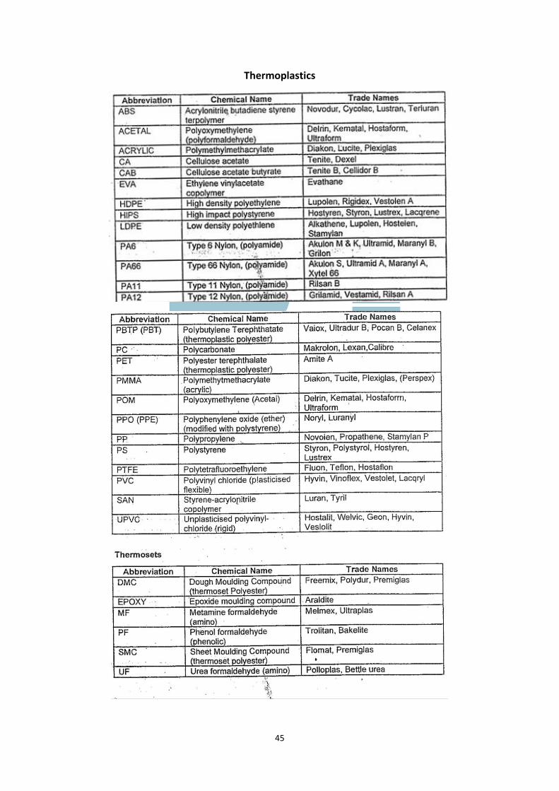
45
Thermoplastics
46
GLOSSARY OF TERMS USED IN THE HF WELDING INDUSTRY
Anode Current
The electrical current flowing from the anode(s) of the generator’s output valve(s). This current gives an indication of
the output power of the generator and is dependant on the setting of the output power control (usually a variable
capacitor) which resonates the generator’s output tuned circuit. The current is also dependent on the loading effect of
the electrode and tooling on the tuned circuit.
Appliqué an Welding
Welding process where a piece of material is cut out and welded to the surface of another to provide ornamental effect.
Arcing
An electrical “flashover” which occurs if the welding machine’s electrodes (i.e. the platen at HF potential and the
worktable at zero HF potential) come too close together or touch. Arcing can damage both the generator and the
tooling, therefore arcing anticipator circuits are usually incorporated in welding machines to cut off the HF power before
damage is caused.
Barrier Material (Buffer Material)
A thin sheet of dielectric that is placed between the work material and the welding machine’s lower platen to reduce
heat loss, and in tear-seal welding to prevent damage to the tooling. Any material used as a barrier must be able to be
repeatedly used in the electric field without being affected.
Blind effects onto Embossing
A technique which can be incorporated into the welding process to place lettering, logos or decorative the welded items.
Calendered and PVC
PVC which has been finished by passing between heated metal rollers which impart the required finish thickness of the
product.
Cooling Time
The time between the end of the Welding Time and the lifting of the tooling from the workpiece.
Dielectric material
Any, solid, liquid or gas which can sustain an electric field, hence an insulator. When a thermoplastic is HF welded, it
acts as a dielectric between the electrodes.
Electrode
A conductor through which an electric current enters or leaves an electrolyte. In HF welding, the term electrodes refers
to the platen and the worktable. In this case, the electrolyte is the thermoplastic being welded.
Frequency
The rate of repetition of a periodic disturbance, measured in hertz (Hz) (cycles per second). In High Frequency qwelding,
the most commonly used frequency for welding is 27.12 MHz
HF
The abbreviation for High Frequency, the range of Radio Frequencies between 3,000 and 30,000 kHz or 3 and 30 MHz.
47
Plain Welding
The welding of two or more layers of thermoplastic material by applying HF power to heat and thereby fuse the inner
surfaces.
Platen
The upper electrode of a welding machine.
Polyolefins
Fibre of film made from a linear polymer obtained from an olefin especially ethylene (giving polyethylene) or propylene
(giving polypropylene).
Power Control
A device, usually a variable resistor or capacitor located in the power output stage of a generator, which enables the HF
output level of a welding machine to be adjusted.
Pressure
The force applied to the workpiece materials to compress them during the welding cycle.
PVC
Polyvinyl chloride – The best know and most widely used of the vinyl plastics.
RF
Radio Frequency – The spectrum of frequencies between 10 kHz and 3 GHz. Within this spectrum, frequencies are split
into Low Frequency (LF), Medium Frequency (MF), High Frequency (HF), Very High Frequency (VHF) etc. Note that RF
is the generic abbreviation for radio frequencies and is sometimes misleadingly used instead of HF.
Stick Weld
A weld where the two surfaces to be joined fail to become perfectly homogenous. The weld often appears to be normal,
and a special technique of static loading is necessary to ascertain whether the weld is satisfactory.
Tear-Seal Welding
The dual process of simultaneously welding and cutting a material. This is achieved by incorporating a cutting edge
adjacent to the welding edge.
Thermoplastic
Becoming plastic on being heated. Specifically any resin which can be melted by heat and then cooled, the process being
repeatable any number of times without appreciable change in properties.
Tuned Circuit
An arrangement of reactive components (inductors and capacitors), connected in series of parallel to offer a low or high
impedance respectively, to an alternating current at the resonant frequency. HF generators use a series tuned circuit to
match the output of valve(s) to the impedance of the welding head components. This matching enables the maximum
transfer of HF power.
Welding Time
The length of time that the HF power is applied to, and creates heat in the workpiece.
Related Documents


![Emballasjedagene 2015 Ultrasonic Welding Technology 1 · Ultrasonics Inc. USA New construction in ... application and process ... Ultrasonic Welding Technology f [Hz] frequency a](https://static.cupdf.com/doc/110x72/5b14827c7f8b9a487c8d5a09/emballasjedagene-2015-ultrasonic-welding-technology-1-ultrasonics-inc-usa-new.jpg)