ELECTRONIC FLUORESCENT ADVANCE, 10275 WEST HIGGINS ROAD, ROSEMONT, IL 60018. TEL: (847) 390-5000, FAX: (847) 390-5109 HIGH FREQUENCY ELECTRONIC BALLASTS

Welcome message from author
This document is posted to help you gain knowledge. Please leave a comment to let me know what you think about it! Share it to your friends and learn new things together.
Transcript

ELEC
TRON
ICFL
UORE
SCEN
T
A D V A N C E , 1 0 2 7 5 W E S T H I G G I N S R O A D , R O S E M O N T, I L 6 0 0 1 8 . T E L : ( 8 4 7 ) 3 9 0 - 5 0 0 0 , F A X : ( 8 4 7 ) 3 9 0 - 5 1 0 9
HIGH FREQUENCY ELECTRONIC BALLASTS

ELECTRONICFLUORESCENT
HIGH FREQUENCY ELECTRONIC BALLASTS
A D V A N C E , 1 0 2 7 5 W E S T H I G G I N S R O A D , R O S E M O N T, I L 6 0 0 1 8 . T E L : ( 8 4 7 ) 3 9 0 - 5 0 0 0 , F A X : ( 8 4 7 ) 3 9 0 - 5 1 0 9 1-1
Visit our web site at www.advancetransformer.com
Contents
General Information .............................................................. 1-2 to 1-25
Compact Fluorescent Lamps ..............................................1-26 to 1-39
CFL
PLH
Long Twin Tubes
2D
Linear Fluorescent Lamps ..................................................1-40 to 1-69
T5
T5 and T5/HO Cirline
T5/HO
T8
T8 Slimline
T8/HO
T10 and T12
T12 Slimline
T12/HO
Note:
Refer to pages 8-14 to 8-30 for Ballast Specifications
Customer Support/Technical Service(800) 372-3331 • (+) 1 847 390-5000 (International)
Corporate Offices(800) 322-2086

ELEC
TRON
ICFL
UORE
SCEN
T
A D V A N C E , 1 0 2 7 5 W E S T H I G G I N S R O A D , R O S E M O N T, I L 6 0 0 1 8 . T E L : ( 8 4 7 ) 3 9 0 - 5 0 0 0 , F A X : ( 8 4 7 ) 3 9 0 - 5 1 0 9
HIGH FREQUENCY ELECTRONIC BALLASTS
1-2
Fluorescent Ballasts - Electronic - Standard Electronic
For T8 and T12 Instant or Rapid Start Fluorescent Lamps and for 39 Watt, 40 Watt,and 50 Watt T5 Rapid Start Long Twin Tube Lamps
Reliable and energy-efficient, Advance's broad line of standard electronic ballasts for T8, T12,and T5 fluorescent lamps offers proven performance and fast payback of investment based on theup to 40% energy savings they drive relative to standard magnetic ballast models. A widely popu-lar product that also qualifies for rebates by a host of utility demand-side management programsnationwide, Advance's line of standard electronic ballasts are ideal for a broad range of commer-cial retrofit and new construction applications.
Advance's standard electronic ballasts are ideal for general office applications as well as conference, meeting, and board rooms.
Features Benefits
Reduces lighting costs by up to 20% when installedwith modern, energy-efficient lamps in building retrofits
Enhances design flexibility and user satisfaction
Delivers flicker-free operation
Enhances ease of installation in retrofit applications
Insures customer security and satisfaction
Energy-efficient design
Operates up to 75% quieter than conventional magnetic ballasts
High frequency operation
Fits the exact footprint of the magnetic ballasts they replace
Backed by 5-year warranty

ELECTRONICFLUORESCENT
HIGH FREQUENCY ELECTRONIC BALLASTS
A D V A N C E , 1 0 2 7 5 W E S T H I G G I N S R O A D , R O S E M O N T, I L 6 0 0 1 8 . T E L : ( 8 4 7 ) 3 9 0 - 5 0 0 0 , F A X : ( 8 4 7 ) 3 9 0 - 5 1 0 9 1-3
Fluorescent Ballasts - Electronic - Centium®
Standard or Small Can for T8 and T12 Instant or Rapid Start Fluorescent Lampsand Micro Can for T8 and T5 Instant Start Fluorescent Lamps
Reliable and energy-efficient, Advance's broad line of Centium high frequency electronic ballastsfor T8 and T12 fluorescent lamps offers all of the energy-saving properties of Advance's standardelectronic line plus the added benefits of extended life and small can size options for enhancedflexibility and versatility. Possessing the same wiring configuration and mounting dimensions asstandard size ballasts, Advance's Centium line is an optimal choice for a broad range of new con-struction and retrofit applications within the commercial sector.
Centium is ideal for general office lighting, conference, meeting, and board room applications,indirect and decorative lighting, and new fixture designs requiring smaller ballasts.
Features Benefits
Reduces lighting costs by up to 20% when installedwith modern, energy-efficient lamps in building retrofits
Enhances accuracy of ordering and reduces SKUrequirements
Optimizes fit for applications where long lamp life orfrequent switching is required
Provides silent, flicker-free operation
Insures customer security and satisfaction
Energy-efficient design
Many instant start models feature IntelliVoltmultiple-voltage technology (enablingoperation from 120 to 277 volts, 50/60Hzwith sustained variation of +/-10%)
Specialized electronic circuitry
High frequency operation
Backed by 5-year warranty

ELEC
TRON
ICFL
UORE
SCEN
T
A D V A N C E , 1 0 2 7 5 W E S T H I G G I N S R O A D , R O S E M O N T, I L 6 0 0 1 8 . T E L : ( 8 4 7 ) 3 9 0 - 5 0 0 0 , F A X : ( 8 4 7 ) 3 9 0 - 5 1 0 9
HIGH FREQUENCY ELECTRONIC BALLASTS
1-4
Fluorescent Ballasts - Electronic - Optanium®
High-efficiency electronic ballasts for a broad range of T5 and T8 lighting systems
Versatile and high-performing, Advance's Optanium® high-efficiency electronic ballasts optimizeenergy savings and are compatible with T5 high efficiency lamps and the market's wide variety ofT8 fluorescent lamp options -- from standard 32-watt, 40-watt, 25-watt, and 17-watt lamps to 4-foot energy-saving 30-watt, 28-watt, and 25-watt models -- delivering maximum flexibility andfreedom of choice. Offered in both instant start as well as programmed start options and inGeneration 1.0 (dedicated voltage) and Generation 2.0 (incorporating True PerformanceTechnologySM and IntelliVolt® multiple voltage technology) versions.
Advance's Optanium family optimizes lumen-per-watt performance and delivers a high-efficiencysolution for a broad range of commercial, industrial, and institutional applications.
Features Benefits
Advance's exclusive technology of engineered componentsoptimizes T8 system performance, resulting in maximumenergy savings, highest lumens-per-watt, and lowest cost ofsystem ownership
Maximizes flexibility and freedom of choice, regardless ofwhether the application involves long burn hours (IS), frequent switching (PS), or use with occupancy sensorsand/or in frequent on/off areas (PS)
Reduces lamp striation typically seen in energy saving lamps
These and other standard features within the Optanium 2.0line reduce maintenance concerns and enhance safety
Delivers reliable performance in a wide range of extremeconditions
Advance's exclusive extended system warranty protection,which matches any lamp manufacturer's published lamp-ballast system warranty, plus adds 90 days of additionalwarranty protection—on both the lamp and ballast!
True Performance TechnologySM (TPT)
Available in Instant Start and Programmed Startmodels to support the market's broad range ofhigh-efficiency T8 lamp applications
Anti-striation circuitry
Lamp auto-restrike circuitry (Instant StartOnly) and anti-arcing technology
Cold-start capability down to -20°F (onOptanium 2.0 Instant Start models operating32-watt lamps only)
PLUS 90 Protection®

ELECTRONICFLUORESCENT
HIGH FREQUENCY ELECTRONIC BALLASTS
A D V A N C E , 1 0 2 7 5 W E S T H I G G I N S R O A D , R O S E M O N T, I L 6 0 0 1 8 . T E L : ( 8 4 7 ) 3 9 0 - 5 0 0 0 , F A X : ( 8 4 7 ) 3 9 0 - 5 1 0 9 1-5
Fluorescent Ballasts - Electronic - Mark 5™
Programmed Start Integrated Circuit Electronic Ballast for 1, 2, and 3 32-Watt, 25-Watt, and 17-Watt T8 Fluorescent Lamps
Designed for easy installation in new construction and retrofit settings, Advance's new andimproved Mark 5 Programmed Start ballasts for 1, 2, and 3 32-Watt, 25-Watt, and 17-Watt T8 fluorescent lamps offer a wide range of features for specialized lighting applications. The Mark 5'sunique integrated circuit-based control technology monitors lamp and ballast conditions to insureoptimum lighting system performance.
Mark 5 is ideal for a wide variety of new construction and retrofit applications.
Features Benefits
Provides extended lamp life in frequent switching applications (up to 50,000 starts)
Reduces potential for neutral and line conductoroverheating
Delivers optimal lighting system performance
Enhances accuracy of ordering and reduces SKUrequirements
Reduces potential interference with infrared remotecontrol systems
Programmed start technology
Total harmonic distortion (THD) below10% for all lamp combinations in anyapplication
Custom integrated circuit monitors lampand ballast conditions
IntelliVolt® multiple-voltage technology(enabling Mark 5's operation at any inputvoltage from 90 to 305 volts, 50/60Hz)
Operation above 42 Khz

ELEC
TRON
ICFL
UORE
SCEN
T
A D V A N C E , 1 0 2 7 5 W E S T H I G G I N S R O A D , R O S E M O N T, I L 6 0 0 1 8 . T E L : ( 8 4 7 ) 3 9 0 - 5 0 0 0 , F A X : ( 8 4 7 ) 3 9 0 - 5 1 0 9
HIGH FREQUENCY ELECTRONIC BALLASTS
1-6
Fluorescent Ballasts - Electronic - SmartMate®
Electronic Ballasts for 4-Pin Compact Fluorescent Lamps
Offering maximum versatility, Advance's SmartMate electronic ballasts for 4-pin compact fluores-cent lamps drive a broad range of quad and triple-tube, circline, 2D, and long twin-tube lamps.Representing an innovative breakthrough in CFL ballast technology, SmartMate's energy-efficientdesign, compact and lightweight housing, and user-friendly features make SmartMate an idealchoice for fixture manufacturers, retrofitters, and MRO replacement.
SmartMate is ideal in such applications as restaurants, reception areas, conference and meetingrooms, hotel and convention center ballrooms, and houses of worship, as well as in place ofincandescent down-lighting systems.
Features Benefits
Reduces SKU requirements and inventory costs, as unit can be used with side or bottom exit leads
Enhances wiring accuracy and ease ofassembly/installation
Ideal for Hotel/Hospitality applications
Enhances accuracy of ordering and reduces SKUrequirements
Safely removes power to the lamp(s)
Color-coded dual-entry connector
Color coded, poke-in terminals
Quik Start models available which startlamps <1.0 seconds
IntelliVolt® multiple-voltage technology(enabling operation from 120 to 277 volts,50/60Hz)
End-of-lamp-life protection

ELECTRONICFLUORESCENT
HIGH FREQUENCY ELECTRONIC BALLASTS
A D V A N C E , 1 0 2 7 5 W E S T H I G G I N S R O A D , R O S E M O N T, I L 6 0 0 1 8 . T E L : ( 8 4 7 ) 3 9 0 - 5 0 0 0 , F A X : ( 8 4 7 ) 3 9 0 - 5 1 0 9 1-7
Fluorescent Ballasts - Electronic - Matchbox™
Miniaturized Electronic Ballasts for 4-pin Compact Fluorescent and T5 Linear Lamps
Packaged in a lightweight, miniature housing relative to standard ballast products, Advance's 120VMatchbox line of energy-efficient electronic ballasts for T5 linear (8-14W) and 4-Pin CompactFluorescent (7-26W) lamps offer the combined benefits of enhanced design flexibility and signifi-cant energy savings (up to 25% energy savings compared to electromagnetic ballasts and up to75% savings over incandescent systems).
Matchbox is ideal in undercabinet, task, ambient, and sign lighting applications as well as in hallsand staircases. Matchbox ballasts meet the Energy Star residential ballast requirements.
Features Benefits
Provides flicker-free starting
Enhances wiring accuracy and ease ofassembly/installation
Delivers energy savings, low temperature starting (0° F), improved lamp life over 2-pin models, and no audible noise
Insures approval for use in residential applications
Safely removes power to the lamp(s)
Instant-on feature
Color-coded, poke-in-connectors
Electronic design
Class B FCC EMI Rating meets Energy Starand consumer EMI requirements
End-of-lamp-life protection
Note; Matchbox ballasts are part of the AmbiStar family

ELEC
TRON
ICFL
UORE
SCEN
T
A D V A N C E , 1 0 2 7 5 W E S T H I G G I N S R O A D , R O S E M O N T, I L 6 0 0 1 8 . T E L : ( 8 4 7 ) 3 9 0 - 5 0 0 0 , F A X : ( 8 4 7 ) 3 9 0 - 5 1 0 9
HIGH FREQUENCY ELECTRONIC BALLASTS
1-8
Fluorescent Ballasts - Electronic - AmbiStar™
Electronic Ballasts for 4-pin Compact Fluorescent and T5, T8 or T12 Linear Lamps
Advance's family of electronic ballasts specifically designed for popular fluorescent applicationsin homes and other non-commercial environments brings all of the energy-efficient benefits offluorescent lighting to residential and hospitality applications. FCC Class B EMI compliant andavailable for T5 linear (8-14W), T8 linear (17-32W), T12 linear (34W-40W) and 4-pin CFL lamps.Advance's AmbiStar ballasts are compact and lightweight, provide quick starting and save userssignificant energy costs relative to alternative lighting sources.
Features Benefits
Provides flicker-free starting
Increased energy savings over incandescent and fluorescent magnetic with no audible noise
Insures approval in residential applications
Safely removes power to the lamp(s)
Less than 1.0 second starting
Electronic design
Class B FCC EMI Rating meets Energy Starand consumer EMI requirements
End-of-lamp-life protection for T5 lampsand smaller

ELECTRONICFLUORESCENT
HIGH FREQUENCY ELECTRONIC BALLASTS
A D V A N C E , 1 0 2 7 5 W E S T H I G G I N S R O A D , R O S E M O N T, I L 6 0 0 1 8 . T E L : ( 8 4 7 ) 3 9 0 - 5 0 0 0 , F A X : ( 8 4 7 ) 3 9 0 - 5 1 0 9 1-9
Fluorescent Ballasts - Electronic - PowrKut®
Low Frequency Electronic Ballasts for T8, T10, and T12 Rapid Start Fluorescent Lamps
Advance's PowrKut low frequency electronic ballasts combine the proven performance of electro-magnetic circuitry with the energy savings capabilities of electronics to provide a cost-effective,energy-efficient solution that offers maximum protection against electromagnetic and radio fre-quency interference (EMI/RFI).
Advance's PowrKut ballast is ideal in such applications as office spaces at industrial sites, healthcare facilities, consumer electronics retail stores, libraries, educational institutions, radio and television studios, and in any settings where EMI and/or RFI are a concern.
Features Benefits
Delivers up to a 26% reduction in energy costs compared to "standard" electromagnetic ballasts
Protects against transients or voltage surges.Compatible with powerline carrier systems
Eliminates possible interference with infrared control systems, radio or television reception, orportable phone transmission
Provides greater flexibility relative to installation
Ballasts are available for more than 90% of fluorescent applications in the market
Unique PowrKut design
Hybrid design with core & coil input
Ability to operate lamps at 60Hz
Open mounting distance for remote or tandem wiring
Operates T8, T10, and T12 standard andenergy-savings lamps

ELEC
TRON
ICFL
UORE
SCEN
T
A D V A N C E , 1 0 2 7 5 W E S T H I G G I N S R O A D , R O S E M O N T, I L 6 0 0 1 8 . T E L : ( 8 4 7 ) 3 9 0 - 5 0 0 0 , F A X : ( 8 4 7 ) 3 9 0 - 5 1 0 9
HIGH FREQUENCY ELECTRONIC BALLASTS
1-10
Electronic Ballast Fundamentals
The job of a ballastIn all fluorescent lighting systems, the ballast’s basic tasks
include:• Providing the proper voltage to establish an arc between the
two electrodes.• Regulating the electric current flowing through the lamp to
stabilize light output.In some fluorescent lighting systems, the ballast also provides
a controlled amount of electrical energy to preheat or maintain thetemperature of the lamp electrodes at levels specified by the man-ufacturer. This is required to prevent electrode filaments deterio-rating prematurely and shortening the lamp life.
Starting MethodsFor many years there were only three types of lighting systems:
preheat, rapid start and slimline instant start. With the introductionof electronic ballasts, two additional types of lighting system cir-cuits have been added: instant start for T8 lamps and programmedstart. Each requires a special ballast design to operate the lampsin the circuit properly.
Instant start electronic ballasts start lamps without delay (<0.1seconds) or flicker by providing a starting voltage that is suffi-ciently high to start a discharge through the lamps without theneed for heating lamp electrodes. For F32T8 systems, the startingvoltage is about 600V. The elimination of electrode heating maxi-mizes energy savings – typically saving two watts per lamp com-pared to rapid start ballasts. Instant start ballasts are best suitedfor applications with limited switches each day. Lamps operated byinstant start ballasts typically operate 10,000 to 15,000 switchcycles before failure.
Rapid start electronic ballasts start lamps quickly (0.5 – 1.0 sec-onds) without flicker by heating the lamp electrodes and simulta-neously applying a starting voltage. The starting voltage of about500V for F32T8 systems is sufficient to start a discharge throughthe lamps when the electrodes have reached an adequate temper-ature. Electrode heating continues during operation and typicallyconsumes two watts per lamp. Lamps operated by rapid start ballasts typically operate 15,000 to 20,000 switch cycles beforefailure.
Programmed start electronic ballasts also start lamps quickly(1.0 -1.5 seconds) without flicker. Programmed start ballasts aredesigned to provide maximum lamp life in frequent lamp startingapplications such as in areas where occupancy sensor controls areused. Programmed start electronic ballasts precisely heat the lampelectrodes, tightly controlling the preheat duration before applyingthe starting voltage. This enhancement over rapid start ballastsminimizes electrode stress and depletion of emitter material,thereby maximizing lamp life. Lamps operated by programmedstart ballasts typically operate up to 50,000 switch cycles beforefailure.
CircuitsSeries vs. Parallel. Lighting systems are typically wired in a
series or parallel circuit. When a ballast is operating multiplelamps in a series circuit, if one lamp fails, the circuit is opened andall the lamps will extinguish. When a ballast operates multiplelamps in a parallel circuit, the lamps operate independently of eachother so, if one lamp fails, the others can keep operating as the cir-cuit between them and the ballast remains unbroken.
BF = light output of lamp operated on commercial ballast
light output of lamp operated on reference ballast
Ballast Efficacy Factor =Ballast Factor x 100
Input Watts
As a general rule, rapid start ballasts are wired with the lampsin series. Programmed start ballasts are also typically wired withlamps in series. However, some three- and four-lamp ballasts fea-ture series-parallel operation; so that when a single lamp in onebranch fails, the lamp(s) in the parallel branch will continue tooperate. Instant start ballasts are typically wired with the lamps inparallel.
The Language of BallastsInput Voltage (dedicated vs. multi). Most ballasts are designed
to operate at specific voltages. Newer electronic ballasts, includingAdvance models that use IntelliVolt® technology, offer muchgreater flexibility and other advantages such as inventory reduc-tion. Today’s increasing demands on electrical utilities can causewide voltage variations during load demand changes which in turncause light output from lamps operated on dedicated electronicand electromagnetic ballasts to vary with the input voltagechanges. With IntelliVolt technology, many Advance ballasts main-tain constant light output through nominal input voltage ranges of120 to 277 volts, thereby compensating for any change in inputvoltage.
Input Watts/ANSI Watts. Input watts published by ballast man-ufacturers are the total watts consumed by both the ballast and thelamps it operates. ANSI watts are the rating given for a ballastmeasured under the strict testing procedures specified by ANSIstandards and are the only dependable measure of this perform-ance. Energy savings can be determined by comparing the inputwatts of different lighting systems.
Ballast Factor (BF) is the ratio of light output from a lamp oper-ated on a commercial ballast to the light output of that same lampoperated on a “reference ballast” as specified by ANSI standards.Light output ratings published by lamp manufacturers, are basedon this “reference ballast”.
BF is a measure of light output best thought of as a ‘multiplier’.Multiplying the BF times rated lumens will determine actual lightoutput of a given system operated on commercial ballasts.
Ballast Efficacy Factor (BEF) is the ratio of ballast factor to inputwatts. This measurement is generally used to compare the effi-ciency of various lighting systems – higher numbers being moreefficient.
This comparison is only valid, however, for ballasts operatingthe same number and type of lamps. In order to compare differenttypes of lighting systems, the lumen output of the lamps must alsobe used. For more information, see “The ABC’s of ElectronicFluorescent Ballasts”.

ELECTRONICFLUORESCENT
HIGH FREQUENCY ELECTRONIC BALLASTS
A D V A N C E , 1 0 2 7 5 W E S T H I G G I N S R O A D , R O S E M O N T, I L 6 0 0 1 8 . T E L : ( 8 4 7 ) 3 9 0 - 5 0 0 0 , F A X : ( 8 4 7 ) 3 9 0 - 5 1 0 9 1-11
Total Harmonic Distortion (THD). Harmonic distortion occurswhen the wave-shape of current or voltage varies from a pure sinewave. Except for a simple resistor, all electronic devices, includingelectromagnetic and electronic ballasts, contribute to power-linedistortion. For ballasts, THD is generally considered the percentof harmonic current the ballast adds to the power distribution system. The ANSI standard for electronic ballasts specifies a maximum THD of 32%. However, most electric utilities nowrequire that the THD of electronic ballasts be 20% or less. Almostall Advance electronic ballasts are rated for either less than 20% THD or less than 10% THD.
PF = Input Watts
Input Current x Input Voltage
High Power Factor (HPF) 0.90 or greater
Power Factor Corrected (PFC) 0.80 to 0.89
Normal (Low) Power Factor (NPF) 0.79 or less
A ballast’s power factor may be classified under any oneof the following categories:
Non-Dimming Applications
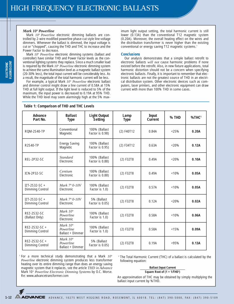
When selecting a ballast for a lighting application, the TotalHarmonic Current (THC) rating of the ballast is more significantthan Total Harmonic Distortion (THD). This is because the absolutevalue of harmonic current, not the percentage, affects the electricalpower distribution system. As can been seen in the table on page1-12, the THC rating of our Standard 2-lamp electronic T8 lamp ballast is well below that of both the conventional and energy-saving magnetic T12 lamp ballasts it replaces. Moreover, the THCrating of our Centium electronic ballast is even lower.
Dimming Applications
Mark 7® 0-10V and ROVRTraditional low voltage controlled ballasts and ROVRTM typically
produce less than 10% THD at full light output and less than 20% THD throughout the entire dimming range, but require extrawires for the control circuit. THC is always lower than that of theconventional or energy-saving magnetic system.
Actual Waveform
Third Harmonic (180Hz)
60 Hz SineWave
Phase A
Phase BLow Current
Neutral Wire If low Third Harmonicon balanced system
Phase C
Phase A
Phase B100% Plus Current
Neutral Wire(Overheated)
Third HarmonicPhase C
Power Factor (PF) is the measurement of how effectively a ballast converts the voltage and current supplied by the powersource into watts of usable power delivered to the ballast and lamps.Perfect power utilization would result in a power factor of one.
Power factor measurements pertain only to the effective use ofpower supplied to the ballast. They are not an indication of the ballast’s ability to supply light through the lamps. Because lowpower factor ballasts require about twice the current needed byhigh power factor ballasts, they allow fewer fixtures per circuit andcreate added wiring costs. High power factor ballasts are generallyspecified for all commercial lighting applications.
EMI/RFI. Because they operate at high frequency, electronicballasts may produce electromagnetic interference (EMI) or radiofrequency interference (RFI). RFI frequencies are a subset of EMIfrequencies. EMI issues cover all possible operating frequencieswhile RFI is only concerned with radio and television frequencies.This interference could affect the operation of sensitive electricalequipment, such as radios, televisions or medical equipment. AllAdvance electronic ballasts incorporate features necessary to afford maximum protection for the operating environment andoperate well within regulatory limits. For more information, see “The ABC’s of Electronic Fluorescent Ballasts”.
Ballast Noise. The slight “humming” sound associated with fluorescent lighting systems results from vibration caused by theinherent electromagnetic action in the core-and-coil assembly ofthe ballasts. All electromagnetic and some electronic ballasts makethis sound. Ballasts are assigned a sound rating, “A” through “F”,based on the amount of sound produced, with “A” being the quietest. Generally, the larger the lamp and ballast, the higher thesound level and the sound rating will be. Because electronic ballasts have smaller components, they have the lowest sound rating. Some electronic ballasts make almost no sound. There isno ANSI standard for this rating and it is left up to the manufac-turer to rate their ballasts.
Inrush Current. All electrical devices including ballasts have an initial current surge that is greater than their steady-state operating current. A new standard published by the NationalElectrical Manufacturers Association (NEMA) – NEMA 410 –Performance Testing for Lighting Controls and Switching Deviceswith Electronic Fluorescent Ballasts – covers worst-case ballastinrush currents. All circuit breakers and light switches aredesigned for inrush currents. The electrical system should bedesigned with this issue in mind.
ELEC
TRON
ICFL
UORE
SCEN
T
A D V A N C E , 1 0 2 7 5 W E S T H I G G I N S R O A D , R O S E M O N T, I L 6 0 0 1 8 . T E L : ( 8 4 7 ) 3 9 0 - 5 0 0 0 , F A X : ( 8 4 7 ) 3 9 0 - 5 1 0 9
HIGH FREQUENCY ELECTRONIC BALLASTS
1-12
AdvancePart No.
BallastType
Light OutputSetting
LampType
InputCurrent % THD %THC2
RQM-2S40-TP ConventionalMagnetic
100% (BallastFactor is 0.98) (2) F40T12 0.84A <25% 0.20A
R2S40-TP Energy SavingMagnetic
100% (BallastFactor is 0.95) (2) F34T12 0.63A <20% 0.12A
REL-2P32-SC StandardElectronic
100% (BallastFactor is 0.88) (2) F32T8 0.49A <20% 0.10A
ICN-2P32-SC CentiumElectronic
100% (BallastFactor is 0.88) (2) F32T8 0.49A <10% 0.05A
IZT-2S32-SC +Dimming Control
Mark 7® 0-10VElectronic
100% (BallastFactor is 1.0) (2) F32T8 0.57A <10% 0.05A
IZT-2S32-SC +Dimming Control
Mark 7® 0-10VElectronic
5% (BallastFactor is 0.05) (2) F32T8 0.12A <20% 0.02A
REZ-2S32-SC(Ballast Only)
Mark 10®
PowerlineElectronic
100% (BallastFactor is 1.0) (2) F32T8 0.58A <10% 0.06A
REZ-2S32-SC +Dimming Control
Mark 10®
PowerlineBallast + Dimmer
100% (BallastFactor is 1.0) (2) F32T8 0.58A <15% 0.09A
REZ-2S32-SC +Dimming Control
Mark 10®
PowerlineBallast + Dimmer
5% (BallastFactor is 0.05) (2) F32T8 0.19A <95% 0.13A
Ballast Input CurrentSquare Root of (1 + 1/THD2)
1 For a more technical study demonstrating that a Mark 10®
Powerline electronic dimming system produces less transformerheating over its entire dimming range than does an energy savingmagnetic system that it replaces, see the article THD in AdvanceMark 10® Powerline Electronic Dimming Systems by O.C. Morse.Re: www.advancetransformer.com
2 The Total Harmonic Current (THC) of a ballast is calculated by thefollowing equation:
An approximation of THC may be obtained by simply multiplying theballast input current by %THD.
Table 1: Comparison of THD and THC Levels
Mark 10® PowerlineMark 10® Powerline electronic dimming ballasts are con-
trolled by 2-wire modified powerline phase-cut style line voltagedimmers. Whenever the ballast is dimmed, the input voltage iscut or “chopped”, causing the THD and THC to increase and thePower Factor to decrease.
Mark 10® Powerline electronic dimming systems (ballast andcontroller) have similar THD and Power Factor levels as the con-ventional lighting systems they replace. Since a much smaller loadis required by the Mark 10® Powerline electronic dimming systemto achieve the same illumination level as a magnetic ballast system(20-30% less), the total input current will be considerably less. Asa result, the magnitude of the total harmonic current will be less.
For example, a typical Mark 10® Powerline electronic ballastand dimmer control might draw a line current of 0.58A at 15%THD at full light output. If the light level is reduced to 5% of themaximum, the input power is decreased to 0.19A at 95% THD.While the THD level may seem alarmingly high at the 5% max-
imum light output setting, the total harmonic current is stilllower (0.13A) than the conventional T12 magnetic system(0.20A). Moreover, the overall heating effect on the wires andthe distribution transformer is never higher than the existingconventional or energy saving T12 magnetic systems.1
ConclusionsOur analysis demonstrates that a simple ballast retrofit to
electronic ballasts will not cause harmonic problems if noneexisted before the retrofit. Also, in new fixture applications, totalharmonic distortion should not be a concern when specifyingelectronic ballasts. Finally, it is important to remember that elec-tronic ballasts are not the greatest source of THD in an electri-cal distribution system. Other electronic devices such as com-puters, laser printers, and other electronic equipment can drawcurrent with more than 100% THD in some cases.

ELECTRONICFLUORESCENT
HIGH FREQUENCY ELECTRONIC BALLASTS
A D V A N C E , 1 0 2 7 5 W E S T H I G G I N S R O A D , R O S E M O N T, I L 6 0 0 1 8 . T E L : ( 8 4 7 ) 3 9 0 - 5 0 0 0 , F A X : ( 8 4 7 ) 3 9 0 - 5 1 0 9 1-13
Ballast LifeAdvance fluorescent electronic and magnetic ballasts are
designed and manufactured to engineering standards correlating toan average life expectancy of 50,000 hours of operation at maxi-mum rated case temperature. Since Advance ballasts operatebelow their maximum case temperature in the majority of applica-tions, increased ballast life can be expected. As a rule of thumb, ballast life is doubled for every 10°C reduction in ballast case operating temperature. However, there are many variables, such asinput voltage, ambient temperature, etc. which affect ballast operating temperatures, and therefore ballast life.
Lamp Operating FrequencyElectromagnetic ballasts and the lamps connected to them oper-
ate at an input voltage frequency of 60 Hertz (Hz), 60 cycles per second–which is the standard alternating voltage/current frequencyprovided in North America. Electronic ballasts, on the other hand,convert this 60 Hz input to operate lamps at much higher frequencies above 20 Kilohertz (kHz), 20,000 cycles per second.Advance designs operate above 20 kHz, but avoid certain rangessuch as 30-40 kHz (infrared) and 54-62 kHz (theft deterrent systems) due to interference issues.
Because electronic ballasts function at high frequency, the fluo-rescent lighting systems that they operate can convert power to lightmore efficiently than systems operated by electromagnetic ballasts(See Chart Below). For example, lamps operated on electronic ballasts can produce over 10 percent more light then if operated onelectromagnetic ballasts at the same power levels. In effect, today’selectronic ballasts provide additional energy savings by matchingthe light output from electromagnetic ballasts while operating thelamps at lower power. This is the main reason why electronic ballastsystems are more efficient than magnetic ballast system.
Ligh
t Out
put P
erce
ntag
e
Excitation Frequency
100Hz 1kHz 10kHz 100kHz
114112110108106104102100
Crest Factor =
PeakI
R.M.S.I
R.M.S.I PeakI
Weight and Size AdvantagesSince electronic components in electronic ballasts are smaller
and lighter than the core-and-coil assembly in electromagneticballasts, electronic ballasts can weigh less than half as much ascomparable electromagnetic models. Almost all Advance electronicballasts have a smaller cross-section than electromagnetic ballastsbut maintain the same mounting dimensions. This means that theycan fit into all new fixture designs and can be easily retrofitted intoexisting fluorescent lighting systems.
ControllabilityThe ability of a building’s occupants to control how they light
their space is becoming an increasingly important factor fororganizations in determining what real estate they will lease, buy or invest in. The ability to dim the lights or easily shut themoff completely is a trend fueled not just by a desire to help the envi-ronment, but also by significant economic benefits. These benefitsinclude greater energy efficiency – in terms of reduced HVAC costsas well as energy savings for lighting – more comfortable and productive working environments, and compliance with ever tighterenergy efficiency regulations. Advance offers three families ofelectronic controllable ballasts – ROVR™, Mark 7™ 0-10V and Mark 10™ Powerline – that can provide up to 65% energy savingsover standard T8 fixed light output systems.
Compatibility With Powerline Carrier SystemsA powerline carrier system (PLC) uses electronic wiring devices
to send information via a high frequency signal over the 120V or277V electrical power distribution system of a building. For exam-ple, PLC systems are used in automatic clock systems (mastertime systems) to synchronize all of the clocks in a building or resetthe time after a power outage. They eliminate the need for mainte-nance personnel to reset hundreds of clocks throughout a facility.
In a PLC system, a generator is used to impose a 1 to 4V highfrequency signal on top of the existing voltage sine wave (60 Hz).This signal is generally in the 2500 to 9500Hz range, with someolder systems operating at 19,500Hz or higher. Some electronicballasts which are capacitive can absorb the signal from a PLCsystem. As a result, the signal becomes too weak to be “heard” bythe receiver (like a timeclock) connected to the powerline.
Instant Start vs. Rapid Start Sockets for DimmingWhen using dimming ballasts in fixtures, sockets must be of the
RAPID START type. Many fixtures with T-8 Instant Start electronicballasts use jumpered or “shunted” Instant Start sockets.Controllable ballasts require two distinctly separate wires for eachlamp socket. If you encounter shunted or jumpered sockets in aretrofit application, they must be removed and replaced with RapidStart sockets.
Crest FactorLamp manufacturers use crest factor to determine ballast
performance as it relates to lamp life. Lamp Current Crest Factoris a measurement of current supplied by a ballast to start andoperate the lamp. It is basically the ratio of peak current to RMS(average) current. High crest factor currents may cause the lampelectrodes to wear out faster, reducing lamp life. Crest factorrequirements are regulated by ANSI (American National StandardsInstitute) standards and specified by lamp manufacturers. Forrapid start and instant start T8 lamps the ratio is 1.7 maximum,and for instant start slimline lamps, it is 1.85 maximum.
NONONOYES
SHUNT
Shunted Jumpered
Instant Start SocketsRapid Start Sockets
Color‘A’
Color‘A’
Color‘A’
Color‘A’
Fluorescent Lamp Burn-InToday, most lamp manufacturers do not require the burn-in of lin-
ear fluorescent lamps prior to dimming in order to attain rated lamplife and stable electrical measurements. However, some manufac-turers compact fluorescent lamp sources do require a 100 hourburn-in prior to dimming. Consult your lamp manufacturer for theirlatest requirements.
Improper socket application will damage the ballast and void the ballast warranty.Refer to ballast wiring diagram for proper installation.

ELEC
TRON
ICFL
UORE
SCEN
T
A D V A N C E , 1 0 2 7 5 W E S T H I G G I N S R O A D , R O S E M O N T, I L 6 0 0 1 8 . T E L : ( 8 4 7 ) 3 9 0 - 5 0 0 0 , F A X : ( 8 4 7 ) 3 9 0 - 5 1 0 9
HIGH FREQUENCY ELECTRONIC BALLASTS
1-14
ORDERING INFORMATIONHow to Order
Advance Transformer has developed the industry’s broadest distribution system forelectronic ballasts. More than 3000 stocking distributors nationwide. For information onthe distributor best able to serve your needs, please call 800-372-3331.
• Plan your lighting installation carefully; considerusing the services of a qualified lighting designer
• Consult your local electric utility regarding demandside management rebate programs.
• Select the Advance electronic ballast which bestmatches the requirements of your application. Thetechnical specifications in this catalog (located onpages 8-4 to 8-22) will be useful in obtaining bidsfrom electrical contractors.
• Contact your local Advance distributor. You willfind them to be a helpful supplier of both productsand information.
Corporate Offices(800) 322-2086
Visit our web site atwww.advancetransformer.com
Customer Support/Technical Service
(800) 372-3331+1 (847) 390-5000 (International)
* Many current and all future electronic ballast part numbers will not use the “RH-TP” suffixes even though these ballasts will be thermally protected.** Parallel Wiring Configuration. However, if one lamp fails, all other lamps in the circuit will extinguish.
Electronic Ballast Part Number Breakdown
CFL Mounting/Connector Options
BS = Bottom mounting studs with single entry color coded connectors
LD = Length mounting feet with SmartMate™ dual entry color coded connectors
LS = Length mounting feet with single entry color coded connectors
QS = QuikStart
Linear Fluorescent Mounting/Connector Options
TP* = Thermal Protected2LS = 2 Level Switching
I CF – ––2 S 26 H1 LD
Input Voltage
G = 347VH = IntelliVolt-Hi (347V through 480V, 50/60 Hz)I = IntelliVolt™ (120V through 277V, 50/60 Hz)R = 120VV = 277VX = 220V
Family Name
CF = Compact Fluorescent CN = CentiumDA = ROVRDL = ROVREL = Standard EZ = Mark 10® PowerlineIC = Mark 5®
MB = MatchboxOP = OptaniumZT = Mark 7® 0-10V
Maximum Number of Lamps
Wiring Configuration
D = 2D, seriesM = Modified parallel**P = ParallelQ = Quad CFL, seriesS = SeriesT = Triple CFL, seriesTTS = Long twin tube, seriesTTP = Long twin tube, parallel
Lamp Watts (Primary lamp)
CFL Can Desription
H1 = Hybrid metal / plastic case, size 1L2 = LinearM1 = Metal case, size 1M2 = Metal case, size 2M3 = Metal case, size 3M4 = Metal case, size 4M5 = Metal case, size 5S1 = Square, style 1S2 = Square, style 2SC = Small can
Linear Fluorescent Can Desription
90C = 90˚C maximum case temperature ratingD = ‘D’ canG = ‘G’ canHL = High light outputLW = Low wattMC = Micro canRH* = Reduced harmonicsS = SlimlineSC = Small can

ELECTRONICFLUORESCENT
HIGH FREQUENCY ELECTRONIC BALLASTS
A D V A N C E , 1 0 2 7 5 W E S T H I G G I N S R O A D , R O S E M O N T, I L 6 0 0 1 8 . T E L : ( 8 4 7 ) 3 9 0 - 5 0 0 0 , F A X : ( 8 4 7 ) 3 9 0 - 5 1 0 9 1-15
REMOTE MOUNTING OF ELECTRONIC BALLASTSUnlike magnetic ballasts, electronic ballasts are limited in remote mounting distance from the lamps they operate. The factors limiting
the distance from the electronic ballasts to the lamps are: open circuit voltage as opposed to operating voltage, operating frequency andthe lamp operating current.
As the distance from the high frequency electronic ballasts to the lamp increases, so does the capacitance across the lead wire to thelamp. This increase in capacitance is important for two reasons. First, if the capacitance is too high, there will not be sufficient open circuit voltage across the lamp for proper lamp ignition.
Second, if the lamp is capable of ignition, the increased capacitance will cause a loss in the current to the lamp. The added capacitancecreates what is known as a “shunt” around the lamp; in other words the current will leak from the red wire (or blue) to the yellow, completely bypassing the lamp. The current through the lamp will be reduced, resulting in lower lumens, with the possibility that the lampwill not be capable of sustained operation.
The Mark 7® 0-10V, Mark 10® Powerline, and ROVR dimming ballasts are particularly sensitive to high capacitance associated with longlead wires. The dimming ballast is capable of very low dim levels because constant filament heat is provided to the lamp. If there is anyloss of current, the filament current will be reduced and the lamp will begin to flicker, or it will be completely extinguished. It is also important that the red and blue leads not be twisted together. Twisting the red and blue leads will add capacitance, causing the lamp toflicker at the lower dimming levels.
Open circuit voltage is a function of input voltage in some ballast designs, particularly for dedicated voltage ballasts. Cold temperaturestarting is a function of open circuit voltage. The lead length recommendations in the following table are for normal rated input voltages(120V, 277V, 347V) at 25°C ambient temperature.
In summary, there is a wide range and varying types of electronic ballast architectures that are capable of being remote mounted foran equally wide range of distances. If you are uncertain of the remote mounting restrictions for a particular electronic ballast please consult Technical Services.
REMOTE, TANDEM OR THROUGH WIRING DISTANCES
Notes:1. For Tandem or Through wiring, any lamp can be remote mounted.2. For Tandem or Through wiring, BLUE lamp must be in same fixture as ballast.3. For Tandem or Through wiring, RED lamp must be in same fixture as ballast.4. No Tandem or Through wiring allowed.5. No Remote, Tandem or Through wiring allowed.6. For Tandem or Through wiring, RED lamp and BLUE lamp must be in same fixture as ballast.7. For Tandem or Through wiring, RED lamp and YELLOW lamp must be in same fixture as ballast.(a) Ballast can be Remote, Tandem or Through wired farther than 20'. See page xxx for details.(b) Ballast can be Remote, Tandem or Through wired to a maximum 12 feet between ballast and lampholder for (2)F96T8/HO lamps or 20 feet for all other T8/HO lamps.(c) Ballast can be Remote, Tandem or Through wired to a maximum 10 feet between ballast and lampholder for energy-saving lamps or 20 feet for standard lamps.Use 18 AWG wire or larger

ELEC
TRON
ICFL
UORE
SCEN
T
A D V A N C E , 1 0 2 7 5 W E S T H I G G I N S R O A D , R O S E M O N T, I L 6 0 0 1 8 . T E L : ( 8 4 7 ) 3 9 0 - 5 0 0 0 , F A X : ( 8 4 7 ) 3 9 0 - 5 1 0 9
HIGH FREQUENCY ELECTRONIC BALLASTS
1-16
Note: Ballast should be mounted at center of fixture to minimize lead lengths.

Maximum Lead Length (Feet) for Tandem or Through Wiring(Total length of all wires between ballast and lamp sockets) Application
NoteRemote(max length) Tandem Through Blue Red Yellow Blue/White Brown Orange
Allowed Wiring Configuration
20' NA NA 420' Yes Yes 20' 20' 120' Yes Yes 4' 20' 20' 220' Yes Yes 20' 20' 1No No No 520' Yes Yes 20' 20' 120' Yes Yes 20' 20' 120' Yes Yes 20' 20' 120' Yes Yes 20' 4' 20' 320' Yes Yes 20' 4' 20' 320' Yes Yes 20' 20' 120' Yes Yes 20' 20' 20' 120' Yes Yes 20' 20' 20' 120' NA NA 420' Yes Yes 4' 20' 20' 220' Yes Yes 20' 4' 20' 320' Yes Yes 20' 4' 4' 20' 20' 20' 715' NA NA 4
1-Lamp 15' NA NA 42-Lamp 6' Yes Yes 2' 6' 6' 2
1-Lamp 15' NA NA 4
2-Lamp 6' Yes Yes 2' 6' 6' 2
1-Lamp 15' NA NA 4
2-Lamp 6' Yes Yes 2' 6' 6' 2
1-Lamp 15' NA NA 4
2-Lamp 6' Yes Yes 2' 6' 6' 2
1-Lamp 15' NA NA 4
2-Lamp 6' Yes Yes 2' 6' 6' 2
1-Lamp 15' NA NA 4
2-Lamp 6' Yes Yes 2' 6' 6' 2
6' Yes Yes 2' 6' 6' 2
GCN-1S32GCN-2P32GCN-2S32GCN-2TTP40-SCGCN-3S32GEL-2P32-LW-RH-TPGEL-2P32-SCGEL-2P59GEL-2S32-RH-TPGEL-2S40-RH-TPGEL-3P32-RH-TPGEL-4P32-LWGEL-4P32-RH-TPGK-132-TP (a)GK-2S32-TP (a)HCN-2S54-90CHCN-4S54-90C-2LS-GICF-1D38-H1-LD
ICF-1H120-M4-BSICF-1H120-M4-LD
ICF-2S13-H1-LDCF-2S13-M1-BSICF-2S13-M1-LS
ICF-2S18-H1-LDICF-2S18-M1-BSICF-2S18-M1-LS
ICF-2S26-H1-LDICF-2S26-M1-BSICF-2S26-M1-LS
ICF-2S42-M2-BSICF-2S42-M2-LDICF-2S42-M2-LS
ICF-2S42-90C-M2-BSICF-2S42-90C-M2-LDICF-2S42-90C-M2-LS
ICF-2S70-M4-BSICF-2S70-M4-LD
ELECTRONICFLUORESCENT
HIGH FREQUENCY ELECTRONIC BALLASTS
A D V A N C E , 1 0 2 7 5 W E S T H I G G I N S R O A D , R O S E M O N T, I L 6 0 0 1 8 . T E L : ( 8 4 7 ) 3 9 0 - 5 0 0 0 , F A X : ( 8 4 7 ) 3 9 0 - 5 1 0 9 1-17
For nominal input voltage and 25°C ambient temperature.
Notes:1. For Tandem or Through wiring, any lamp can be remote mounted.2. For Tandem or Through wiring, BLUE lamp must be in same fixture as ballast.3. For Tandem or Through wiring, RED lamp must be in same fixture as ballast.4. No Tandem or Through wiring allowed.5. No Remote, Tandem or Through wiring allowed.6. For Tandem or Through wiring, RED lamp and BLUE lamp must be in same fixture as ballast.7. For Tandem or Through wiring, RED lamp and YELLOW lamp must be in same fixture as ballast.(a) Ballast can be Remote, Tandem or Through wired farther than 20'. See page xxx for details.(b) Ballast can be Remote, Tandem or Through wired to a maximum 12 feet between ballast and lampholder for (2)F96T8/HO lamps or 20 feet for all other T8/HO lamps.(c) Ballast can be Remote, Tandem or Through wired to a maximum 10 feet between ballast and lampholder for energy-saving lamps or 20 feet for standard lamps.Use 18 AWG wire or larger

ELEC
TRON
ICFL
UORE
SCEN
T
A D V A N C E , 1 0 2 7 5 W E S T H I G G I N S R O A D , R O S E M O N T, I L 6 0 0 1 8 . T E L : ( 8 4 7 ) 3 9 0 - 5 0 0 0 , F A X : ( 8 4 7 ) 3 9 0 - 5 1 0 9
HIGH FREQUENCY ELECTRONIC BALLASTS
1-18
For nominal input voltage and 25°C ambient temperature.Notes:1. For Tandem or Through wiring, any lamp can be remote mounted.2. For Tandem or Through wiring, BLUE lamp must be in same fixture as ballast.3. For Tandem or Through wiring, RED lamp must be in same fixture as ballast.4. No Tandem or Through wiring allowed.5. No Remote, Tandem or Through wiring allowed.6. For Tandem or Through wiring, RED lamp and BLUE lamp must be in same fixture as ballast.7. For Tandem or Through wiring, RED lamp and YELLOW lamp must be in same fixture as ballast.(a) Ballast can be Remote, Tandem or Through wired farther than 20'. See page xxx for details.(b) Ballast can be Remote, Tandem or Through wired to a maximum 12 feet between ballast and lampholder for (2)F96T8/HO lamps or 20 feet for all other T8/HO lamps.(c) Ballast can be Remote, Tandem or Through wired to a maximum 10 feet between ballast and lampholder for energy-saving lamps or 20 feet for standard lamps.Use 18 AWG wire or larger
ICN-132-MCICN-1P32-LW-SCICN-1P32-SCICN-1S80ICN-2M32-MCICN-2P32-LW-SCICN-2P32-SCICN-2S24ICN-2S28ICN-2S39ICN-2S54ICN-2S54-90CICN-2S86 (b)ICN-3P32-LW-SCICN-3P32-SCICN-3S14-DICN-4P32-LW-SCICN-4P32-SCICN-4S54-90C-2LSICN-4S54-90C-2LS-GIDA-132-SCIDA-154IDA-2S32-SCIDA-2S54IDA-3S32-GIDA-4S32
IDL-2S26-M5-BSIDL-2S26-M5-LD
IDL-2T42-M5-BSIDL-2T42-M5-LD
IEZ-124-DIEZ-2S24-DIIC-132-SCIIC-2S32-SCIIC-3S32-SCIOP-1P32-HL-SCIOP-1P32-LW-SCIOP-1P32-SCIOP-1S32-LW-SC (c)IOP-1S32-SC (c)IOP-2P32HL-SCIOP-2P32-LW-SCIOP-2P32-SC
20' NA NA 420' NA NA 420' NA NA 120' NA NA 420' Yes Yes 20' 20' 120' Yes Yes 20' 20' 120' Yes Yes 20' 20' 120' Yes Yes 20' 4' 20' 38' Yes Yes 8' 4' 8' 320' Yes Yes 20' 4' 20' 320' Yes Yes 20' 4' 20' 320' Yes Yes 20' 4' 20' 312' Yes Yes 12' 4' 12' 320' Yes Yes 20' 20' 120' Yes Yes 20' 20' 1No No No 520' Yes Yes 20' 20' 20' 120' Yes Yes 20' 20' 20' 120' Yes Yes 20' 4' 4' 20' 20' 20' 720' Yes Yes 20' 4' 4' 20' 20' 20' 7No NA NA 5No NA NA 5No No No 5No No Yes 5' 4' 4' 5No No No 5No No Yes 1' 1.5' 5' 1.5' 4' 5
No No No 5
No No No 5
No NA NA 5No No Yes 3' 2' 2' 520' NA NA 420' Yes Yes 4' 20' 20' 2No No No 520' NA NA 420' NA NA 420' NA NA 410' NA NA 410' NA NA 420' Yes Yes 20' 20' 120' Yes Yes 20' 20' 120' Yes Yes 20' 20' 1
Maximum Lead Length (Feet) for Tandem or Through Wiring(Total length of all wires between ballast and lamp sockets) Application
NoteRemote(max length) Tandem Through Blue Red Yellow Blue/White Brown Orange
Allowed Wiring Configuration

IOP-2P59-SCIOP-2S32-LW-SC (c)IOP-2S32-SC (c)IOP-3P32-HL-90C-SCIOP-3P32-LW-SCIOP-3P32-SCIOP-3S32-LW-SC (c)IOP-3S32-SC (c)IOP-4P32-HL-90C-GIOP-4P32-LW-SCIOP-4P32-SCIOP-4S32-LW-SC (c)IOP-4S32-SC (c)IZT-132-SCIZT-2S26-M5-BSIZT-2S26-M5-LDIZT-2S32-SCIZT-2T42-M3-BSIZT-2T42-M3-LDIZT-2T42-M5-BSIZT-2T42-M5-LDIZT-2TTS40-SCIZT-3S32-SCIZT-4S32RCF-2S13-H1-LDRCF-2S13-M1-BSRCF-2S13-M1-LS
RCF-2S18-H1-LDRCF-2S18-M1-BSRCF-2S18-M1-LS
RCF-2S26-H1-LDRCF-2S26-M1-BSRCF-2S26-M1-LSRCN-1S32-SCRCN-1TTP40-SCRCN-2P59RCN-2S32-SCRCN-2TTP40-SCRCN-3S32-SCRCN-3TTP40-SCRCN-4S32-SC
20' Yes Yes 20' 20' 110' Yes Yes 4' 10' 10' 210' Yes Yes 4' 10' 10' 220' Yes Yes 20' 20' 120' Yes Yes 20' 20' 120' Yes Yes 20' 20' 110' Yes Yes 10' 4' 4' 10' 710' Yes Yes 10' 4' 4' 10' 720' Yes Yes 20' 20' 20' 120' Yes Yes 20' 20' 20' 120' Yes Yes 20' 20' 20' 110' Yes Yes 10' 4' 4' 10' 10' 710' Yes Yes 10' 4' 4' 10' 10' 76' NA NA 4
No No No 5
6' Yes Yes 6' 6' 6' 1
No No No 5
No No No 5
6' No No 4No No No 5No No Yes 1' 1.5' 5' 1.5' 4' 5
1-Lamp 15' No No 4
2-Lamp 6' Yes Yes 2' 6' 6' 2
1-Lamp 15' No No 4
2-Lamp 6' Yes Yes 2' 6' 6' 2
1-Lamp 15' No No 4
2-Lamp 6' Yes Yes 2' 6' 6' 2
20" NA NA 420" NA NA 420" Yes Yes 20' 20' 1No Yes Yes 20' 4' 20' 320" Yes Yes 20' 20' 1No Yes Yes 4' 4' 20' 20' 620" Yes Yes 20' 20' 1No Yes Yes 4' 4' 20' 20' 20' 6
Maximum Lead Length (Feet) for Tandem or Through Wiring(Total length of all wires between ballast and lamp sockets) Application
NoteRemote(max length) Tandem Through Blue Red Yellow Blue/White Brown Orange
Allowed Wiring Configuration
ELECTRONICFLUORESCENT
HIGH FREQUENCY ELECTRONIC BALLASTS
A D V A N C E , 1 0 2 7 5 W E S T H I G G I N S R O A D , R O S E M O N T, I L 6 0 0 1 8 . T E L : ( 8 4 7 ) 3 9 0 - 5 0 0 0 , F A X : ( 8 4 7 ) 3 9 0 - 5 1 0 9 1-19
For nominal input voltage and 25°C ambient temperature.
Notes:1. For Tandem or Through wiring, any lamp can be remote mounted.2. For Tandem or Through wiring, BLUE lamp must be in same fixture as ballast.3. For Tandem or Through wiring, RED lamp must be in same fixture as ballast.4. No Tandem or Through wiring allowed.5. No Remote, Tandem or Through wiring allowed.6. For Tandem or Through wiring, RED lamp and BLUE lamp must be in same fixture as ballast.7. For Tandem or Through wiring, RED lamp and YELLOW lamp must be in same fixture as ballast.(a) Ballast can be Remote, Tandem or Through wired farther than 20'. See page xxx for details.(b) Ballast can be Remote, Tandem or Through wired to a maximum 12 feet between ballast and lampholder for (2)F96T8/HO lamps or 20 feet for all other T8/HO lamps.(c) Ballast can be Remote, Tandem or Through wired to a maximum 10 feet between ballast and lampholder for energy-saving lamps or 20 feet for standard lamps.Use 18 AWG wire or larger

REB-2P32-SCREB-4P32-SCREL-1P32-HL-SCREL-1P32-LW-SCREL-1P32-SCREL-1S40-SCREL-1TTS39REL-1TTS40REL-1TTS50REL-2P17-RH-TPREL-2P32-HL-SCREL-2P32-LW-SCREL-2P32-SCREL-2P59-SCREL-2P59-S-RH-TPREL-2P60-SREL-2S110REL-2S40-SCREL-2S86REL-2TTS39REL-2TTS40REL-2TTS50REL-3P32-HL-SCREL-3P32-LW-SCREL-3P32-SCREL-3S40-RH-TPREL-4P32-LW-SCREL-4P32-SCRELB-2S40-SCREZ-132-SCREZ-154REZ-1Q18-M2-BSREZ-1Q18-M2-LDREZ-1T42-M2-BSREZ-1T42-M2-LDREZ-1TTS40-SCREZ-2Q18-M2-BSREZ-2Q18-M2-LDREZ-2Q26-M2-BSREZ-2Q26-M2-LDREZ-2S32-SCREZ-2S54
20" Yes Yes 20' 20' 120" Yes Yes 20' 20' 20' 120" NA NA 420" NA NA 420" NA NA 420" NA NA 4No NA NA 5No NA NA 5No NA NA 520" Yes Yes 20' 20' 120" Yes Yes 20' 20' 120" Yes Yes 20' 20' 120" Yes Yes 20' 20' 120" Yes Yes 20' 20' 120" Yes Yes 20' 20' 120" Yes Yes 20' 20' 120" Yes Yes 4' 20' 20' 220" Yes Yes 4' 20' 20' 220" Yes Yes 4' 20' 20' 2No No No 5No No No 5No No No 520" Yes Yes 20' 20' 120" Yes Yes 20' 20' 120" Yes Yes 20' 20' 1No No No 520" Yes Yes 20' 20' 20' 120" Yes Yes 20' 20' 20' 110" Yes Yes 4' 10' 10' 26' NA NA 4No NA NA 5
No NA NA 5
No NA NA 5
6' NA NA 4
No No No 5
No No No 5
6' Yes No 6' 6' 6' 1No No Yes 5' 4' 4' 5
Maximum Lead Length (Feet) for Tandem or Through Wiring(Total length of all wires between ballast and lamp sockets) Application
NoteRemote(max length) Tandem Through Blue Red Yellow Blue/White Brown Orange
Allowed Wiring Configuration
ELEC
TRON
ICFL
UORE
SCEN
T
A D V A N C E , 1 0 2 7 5 W E S T H I G G I N S R O A D , R O S E M O N T, I L 6 0 0 1 8 . T E L : ( 8 4 7 ) 3 9 0 - 5 0 0 0 , F A X : ( 8 4 7 ) 3 9 0 - 5 1 0 9
HIGH FREQUENCY ELECTRONIC BALLASTS
1-20
For nominal input voltage and 25°C ambient temperature.Notes:1. For Tandem or Through wiring, any lamp can be remote mounted.2. For Tandem or Through wiring, BLUE lamp must be in same fixture as ballast.3. For Tandem or Through wiring, RED lamp must be in same fixture as ballast.4. No Tandem or Through wiring allowed.5. No Remote, Tandem or Through wiring allowed.6. For Tandem or Through wiring, RED lamp and BLUE lamp must be in same fixture as ballast.7. For Tandem or Through wiring, RED lamp and YELLOW lamp must be in same fixture as ballast.(a) Ballast can be Remote, Tandem or Through wired farther than 20'. See page xxx for details.(b) Ballast can be Remote, Tandem or Through wired to a maximum 12 feet between ballast and lampholder for (2)F96T8/HO lamps or 20 feet for all other T8/HO lamps.(c) Ballast can be Remote, Tandem or Through wired to a maximum 10 feet between ballast and lampholder for energy-saving lamps or 20 feet for standard lamps.Use 18 AWG wire or larger

ELECTRONICFLUORESCENT
HIGH FREQUENCY ELECTRONIC BALLASTS
A D V A N C E , 1 0 2 7 5 W E S T H I G G I N S R O A D , R O S E M O N T, I L 6 0 0 1 8 . T E L : ( 8 4 7 ) 3 9 0 - 5 0 0 0 , F A X : ( 8 4 7 ) 3 9 0 - 5 1 0 9 1-21
For nominal input voltage and 25°C ambient temperature.Notes:1. For Tandem or Through wiring, any lamp can be remote mounted.2. For Tandem or Through wiring, BLUE lamp must be in same fixture as ballast.3. For Tandem or Through wiring, RED lamp must be in same fixture as ballast.4. No Tandem or Through wiring allowed.5. No Remote, Tandem or Through wiring allowed.6. For Tandem or Through wiring, RED lamp and BLUE lamp must be in same fixture as ballast.7. For Tandem or Through wiring, RED lamp and YELLOW lamp must be in same fixture as ballast.(a) Ballast can be Remote, Tandem or Through wired farther than 20'. See page xxx for details.(b) Ballast can be Remote, Tandem or Through wired to a maximum 12 feet between ballast and lampholder for (2)F96T8/HO lamps or 20 feet for all other T8/HO lamps.(c) Ballast can be Remote, Tandem or Through wired to a maximum 10 feet between ballast and lampholder for energy-saving lamps or 20 feet for standard lamps.Use 18 AWG wire or larger
REZ-2T42-M3-BSREZ-2T42-M3-LDREZ-2TTS40-SCREZ-3S32-SCRK-132-TP (a)RK-2S32-TP (a)RK-2S34-TP (a)RMB-1P13-L2RMB-1P13-S1RMB-1P13-S2-HRMB-1P26-S2RMB-2P13-L2RMB-2P13-S2RMB-2P13-S3-HROP-2P32-LW-SCROP-2P32-SCROP-3P32-LW-SCROP-3P32-SCROP-4P32-HL-90C-GROP-4P32-LW-SCROP-4P32-SCRZT-154RZT-1TTS40RZT-2S54VCN-1S32-SCVCN-1TTP40-SCVCN-2P59VCN-2S32-SCVCN-2TTP40-SCVCN-3S32-SCVCN-3TTP40-SCVCN-4S32-SCVEL-1P32-HL-SCVEL-1P32-LW-SCVEL-1P32-SCVEL-1S40-SCVEL-1TTS39VEL-1TTS40VEL-1TTS50VEL-2P17-RH-TPVEL-2P32-HL-SCVEL-2P32-LW-SC
No No No 5
6' No No 4No No No 520' NA NA 420' Yes Yes 4' 20' 20' 220' Yes Yes 4' 20' 20' 220' NA NA 420' NA NA 420' NA NA 420' NA NA 420' Yes Yes 20' 20' 20' 120' Yes Yes 20' 20' 20' 120' Yes Yes 20' 20' 20' 120' Yes Yes 20' 20' 120' Yes Yes 20' 20' 120' Yes Yes 20' 20' 120' Yes Yes 20' 20' 120' Yes Yes 20' 20' 20' 120' Yes Yes 20' 20' 20' 120' Yes Yes 20' 20' 20' 1No NA NA 56' NA NA 4No No Yes 5' 4' 4' 520" NA NA 420" NA NA 420" Yes Yes 20' 20' 1No Yes Yes 20' 4' 20' 320" Yes Yes 20' 20' 1No Yes Yes 4' 4' 20' 20' 620" Yes Yes 20' 20' 1No Yes Yes 4' 4' 20' 20' 20' 620" NA NA 420" NA NA 420" NA NA 420" NA NA 4No NA NA 5No NA NA 5No NA NA 520" Yes Yes 20' 20' 120" Yes Yes 20' 20' 120" Yes Yes 20' 20' 1
Maximum Lead Length (Feet) for Tandem or Through Wiring(Total length of all wires between ballast and lamp sockets) Application
NoteRemote(max length) Tandem Through Blue Red Yellow Blue/White Brown Orange
Allowed Wiring Configuration

ELEC
TRON
ICFL
UORE
SCEN
T
A D V A N C E , 1 0 2 7 5 W E S T H I G G I N S R O A D , R O S E M O N T, I L 6 0 0 1 8 . T E L : ( 8 4 7 ) 3 9 0 - 5 0 0 0 , F A X : ( 8 4 7 ) 3 9 0 - 5 1 0 9
HIGH FREQUENCY ELECTRONIC BALLASTS
1-22
SEE PAGE 1-21 FOR NOTES
For nominal input voltage and 25°C ambient temperature.
VEL-2P32-SCVEL-2P59-SCVEL-2P59S-RH-TPVEL-2P75-SVEL-2S110VEL-2S40-SCVEL-2S86VEL-2TTS39VEL-2TTS40VEL-2TTS50VEL-3P32-HL-SCVEL-3P32-LW-SCVEL-3P32-SCVEL-3S40-RH-TPVEL-4P32-LW-SCVEL-4P32-SCVEZ-132-SCVEZ-154VEZ-1Q18-M2-BSVEZ-1Q18-M2-LDVEZ-1T42-M2-BSVEZ-1T42-M2-LDVEZ-1TTS40-SCVEZ-2Q18-M2-BSVEZ-2Q18-M2-LDVEZ-2Q26-M2-BSVEZ-2Q26-M2-LDVEZ-2S32-SCVEZ-2S54VEZ-2T42-M3-BSVEZ-2T42-M3-LDVEZ-2TTS40-SCVEZ-3S32-SCVK-132-TP (a)VK-2S32-TP (a)VK-2S34-TP (a)VOP-2P32-LW-SCVOP-2P32-SCVOP-3P32-LW-SCVOP-3P32-SCVOP-4P32-HL-90C-GVOP-4P32-LW-SCVOP-4P32-SCVZT-154VZT-180VZT-1TTS40VZT-2S54VZT-4S32-HL
20" Yes Yes 20' 20' 120" Yes Yes 20' 20' 120" Yes Yes 20' 20' 120" Yes Yes 20' 20' 120" Yes Yes 4' 20' 20' 220" Yes Yes 4' 20' 20' 220" Yes Yes 4' 20' 20' 2No No No 5No No No 5No No No 520" Yes Yes 20' 20' 120" Yes Yes 20' 20' 120" Yes Yes 20' 20' 1No No No 520" Yes Yes 20' 20' 20' 120" Yes Yes 20' 20' 20' 16' NA NA 4No NA NA 5
No NA NA 5
No NA NA 5
6' NA NA 4
No No No 5
No No No 5
6' Yes No 6' 6' 6' 1No No Yes 5' 4' 4' 5
No No No 5
6' No No 4No No No 520' NA NA 420' Yes Yes 4' 20' 20' 220' Yes Yes 4' 20' 20' 220' Yes Yes 20' 20' 120' Yes Yes 20' 20' 120' Yes Yes 20' 20' 120' Yes Yes 20' 20' 120' Yes Yes 20' 20' 20' 120' Yes Yes 20' 20' 20' 120' Yes Yes 20' 20' 20' 1No NA NA 5No NA NA 56' NA NA 4No No Yes 5' 4' 4' 5No No Yes 1' 1.5' 5' 1.5' 4' 5
Maximum Lead Length (Feet) for Tandem or Through Wiring(Total length of all wires between ballast and lamp sockets) Application
NoteRemote(max length) Tandem Through Blue Red Yellow Blue/White Brown Orange
Allowed Wiring Configuration

ELECTRONICFLUORESCENT
HIGH FREQUENCY ELECTRONIC BALLASTS
A D V A N C E , 1 0 2 7 5 W E S T H I G G I N S R O A D , R O S E M O N T, I L 6 0 0 1 8 . T E L : ( 8 4 7 ) 3 9 0 - 5 0 0 0 , F A X : ( 8 4 7 ) 3 9 0 - 5 1 0 9 1-23
Reading Date Codes for Warranty Date on Electronic BallastsMost date codes are stamped on the back of the ballast (opposite the label side). The date code is part of a larger group of numbers and
letters, which call out the various codes for the factory where the ballast was manufactured. Depending upon which Advance Transformerfactory manufactured the ballast, the date stamp can vary slightly, in terms of its position on the ballast and the number sequence.
Some electronic ballasts manufactured from 1988 to 1991 may have the date code in ink stamped on the ballast label. Some ballasts havethe manufacturing code printed in ink on the end of the ballast.
A typical date code for an electronic ballast will have the week and the year the ballast was manufactured. Some ballasts will have the dayof the week included too.
ADVANCE TRANSFORMER’S ELECTRONIC BALLASTS HAVE A (5) YEAR WARRANTY FROM DATE OF MANUFACTURE, EFFECTIVE WITHMANUFACTURING IN JANUARY, 1994 (DATE STAMPED 01-94). ELECTRONIC BALLASTS WITH A DATE CODE PRIOR TO THAT DATE, HAVE A THREE YEAR WARRANTY (DATE STAMPED 52-93 OR EARLIER).
Some examples of these different date codes that you may find are:
937N1BB41893The date code is the 18th week of 1993, stamped one line over the other.This ballast has a (3) year warranty, that ends the 18th week of 1996.
937N1JP23292The date code is the 32nd week of 1992, stamped one line over the other.This ballast has a (3) year warranty, that ends the 32nd week of 1995.
1693
973N20P3The date code is the 16th week of 1993, stamped at the end of the ear on the back.This ballast has a (3) year warranty, that ends the 16th week of 1996.
892P259P
2494
The date code is the 4th week of 1994, stamped on four separate lines.This ballast has a (5) year warranty that ends the 4th week of 1999.
91405BB0291NThe date code is the 2nd week of 1991, stamped on one line.This ballast has a (3) year warranty that ends the 2nd week of 1994.
9716T032HD120432IS24The date code is the 16th week of 1997, stamped in ink on the end of the ballast.This ballast has a (5) year warranty that ends the 16th week of 2002.
693P0MMA53397707The date code is the 5th day, of the 33rd week of 1997, stamped on the back of the ballast.
05127M50F2104571The date code is the 127th day of 2005 stamped on the back of the ballast.
FOR ASSISTANCE IN DETERMINING A DATE CODE – CALL TECHNICAL SERVICE AT 1-800-372-3331

ELEC
TRON
ICFL
UORE
SCEN
T
A D V A N C E , 1 0 2 7 5 W E S T H I G G I N S R O A D , R O S E M O N T, I L 6 0 0 1 8 . T E L : ( 8 4 7 ) 3 9 0 - 5 0 0 0 , F A X : ( 8 4 7 ) 3 9 0 - 5 1 0 9
HIGH FREQUENCY ELECTRONIC BALLASTS
1-24
NOW FEATURING PATENT-PENDING MOUNTING PLATE ADAPTER!
Key BenefitsKit Contents and Key Features
SmartMate™ or Mark 10 Powerline ballast• Intellivolt™ Technology• Dual-entry color-coded connectors• Multi-Lamp Capability
Mounting Plate Adapter• Multiple lead wire cutouts, including center hole• Integral mounting studs
Lead Wire• Color-coded• Pre-stripped 3/8" on one end – 5/8" on the other
Wire Extraction Tool
Individually Shrink-Wrapped Kits
Makes ballast selection and installation a breeze• Provides full range input voltage from 120V to 277V• Adds to application versatility; simplifies wiring• Encompasses a wide variety of applications, including• quads, triple tubes, circline, 2D and long twin-tube lamps
Takes the guess-work out of mounting• Allows wiring and mounting to existing fixture’s mounting plate• Eliminates need to stock units with and without studs
Allows installer to pre-wire• Ensures wiring accuracy• Meets UL poke-in connector requirements and facilitates• final connection
Makes for quick disconnections if necessary
Provides fast and accurate identification of ballast and lampapplications
SMARTMATE™ and Mark 10 Powerline Ballast Kits
• Ideally suited for replacement of expired electronic ballasts, regardless of brandor mounting configuration.
• Dramatically simplifies the upgrading of incandescent fixtures to energy-saving CFL.• Compatible with most J-Box covers
ICF-2S13-H1-LD-K* REZ-2Q26-M2-LD-K* * kits contain the standard ICF-2S18-H1-LD-K* VEZ-2Q26-M2-LD-K* ballasts. For lamp and operational dataICF-2S26-H1-LD-K* REZ-1T42-M2-LD-K* consult pages 1-27 through 1-39ICF-2S42-M2-LD-K* VEZ-1T42-M2-LD-K* and 2-7

ELECTRONICFLUORESCENT
HIGH FREQUENCY ELECTRONIC BALLASTS
A D V A N C E , 1 0 2 7 5 W E S T H I G G I N S R O A D , R O S E M O N T, I L 6 0 0 1 8 . T E L : ( 8 4 7 ) 3 9 0 - 5 0 0 0 , F A X : ( 8 4 7 ) 3 9 0 - 5 1 0 9 1-25
NOTES

1-26
T4 HIGH POWER FACTOR SOUND RATED A
HIGH FREQUENCY ELECTRONIC BALLASTS
For 7 - 9W Lamps
A D V A N C E , 1 0 2 7 5 W E S T H I G G I N S R O A D , R O S E M O N T, I L 6 0 0 1 8 . T E L : ( 8 4 7 ) 3 9 0 - 5 0 0 0 , F A X : ( 8 4 7 ) 3 9 0 - 5 1 0 9
ELEC
TRON
ICFL
UORE
SCEN
T
Refer to pages 8-17 to 8-19 for lead lengths and shipping data
S1 Model
1 or 2 lamp linear ballast, plastic enclosure
L2 Model
S2 Model
† Matchbox ballasts are normal power factor except -H models which are high power factor.
S3 Model
See page 1-28 for Wiring Diagrams
No. ofLamps
Min.StartingTemp.(°F/°C)
InputVolts Catalog NumberBallast
Family
LampStartingMethod
Line Current(Amps)
InputPowerANSI
(Watts)
BallastFactor
Max.THD%
Dim. WiringDia.
CFT7W/2G7 - 7W CFL Twin Tube Lamp (CF7DS/E)
1 0/-18120RMB-1P13-L2
Matchbox†IS0.138 1.00 150
L2160RMB-1P13-S1 S1
RMB-1P13-S2-H 0.078 1.00 25 S2
2 0/-18120RMB-2P13-L2
Matchbox†IS0.2416 1.10 150
L2159RMB-2P13-S2 S2
RMB-2P13-S3-H 0.1416 1.00 15 S3
CFT9W/2G7 - 9W CFL Twin Tube Lamp (CF9DS/E)
1 0/-18120RMB-1P13-L2
Matchbox†IS0.1610 1.10 150
L2160RMB-1P13-S1 S1
RMB-1P13-S2-H 0.0910 1.05 20 S2
2 0/-18120RMB-2P13-L2
Matchbox†IS0.2920 1.10 125
L2159RMB-2P13-S2 S2
RMB-2P13-S3-H 0.1720 1.05 10 S3

1-27
T4 HIGH POWER FACTOR SOUND RATED A
HIGH FREQUENCY ELECTRONIC BALLASTS
For 13 - 18W Quad Lamps
A D V A N C E , 1 0 2 7 5 W E S T H I G G I N S R O A D , R O S E M O N T, I L 6 0 0 1 8 . T E L : ( 8 4 7 ) 3 9 0 - 5 0 0 0 , F A X : ( 8 4 7 ) 3 9 0 - 5 1 0 9
ELECTRONICFLUORESCENT
HIGH FREQUENCYELECTRONIC
Refer to pages 8-17 to 8-19 for lead lengths and shipping data See page 1-26 for DimensionsSee page 1-28 for Wiring Diagrams
† Matchbox ballasts are normal power factor except -H models which are high power factor.➀ Replacement/Retrofit ballast kits indicated by Bold Type with suffix K are available to distributors. Refer to page 1-24 for details.
CFQ13W/G24q - 13W CFL Quad Tube Lamp (PL-C13W/4P, F13DBX/4P, CF13DD/E)
1 0/-18
120
RMB-1P13-L2Matchbox†IS
0.2014 1.00 150L2
160
RMB-1P13-S1 S1RMB-1P13-S2-H 0.1214 0.85 20 S2RCF-2S13-H1-LD-QS
AmbiStar
SmartMate
QS
0.1316 1.00 10
Size 1
RCF-2S13-M1-BS-QSRCF-2S13-M1-LS-QS
120-277
ICF-2S13-H1-LD-QSICF-2S13-M1-BS-QSICF-2S13-M1-LS-QS
0.13-0.0616 1.00 10
ICF-2S13-H1-LDICF-2S13-H1-LD-K ➀
PS 0.13-0.0616 1.00 10ICF-2S13-M1-BSICF-2S13-M1-LS
2 0/-18
120
RMB-2P13-L2Matchbox†IS
0.3525 0.95 125L2
159
RMB-2P13-S2 S2RMB-2P13-S3-H 0.2327 0.90 10 S3RCF-2S13-H1-LD-QS
QS
0.2529 1.00 10
Size 1
RCF-2S13-M1-BS-QSRCF-2S13-M1-LS-QS
120-277
ICF-2S13-H1-LD-QSICF-2S13-M1-BS-QSICF-2S13-M1-LS-QS
0.25-0.1129 1.00 10
ICF-2S13-H1-LDICF-2S13-H1-LD-K ➀
PS 0.25-0.1129 1.00 10ICF-2S13-M1-BSICF-2S13-M1-LS
AmbiStar
SmartMate
CFQ18W/G24q - 18W CFL Quad Tube Lamp (PL-C18W/4 P, F18DBX/4P, CF18DD/E)
1 0/-18
120
RMB-2P13-L2Matchbox†IS
0.2616 0.80 150L2
*159RMB-2P13-S2 S2RMB-2P13-S3-H 0.1315 0.80 15 S3RCF-2S18-H1-LD-QS
SmartMate
AmbiStar
QS
0.1619 1.00 10
Size 1 160
RCF-2S18-M1-BS-QSRCF-2S18-M1-LS-QS
120-277
ICF-2S18-H1-LD-QSICF-2S18-M1-BS-QSICF-2S18-M1-LS-QS
0.16-0.0719 1.00 10
ICF-2S18-H1-LDICF-2S18-H1-LD-K ➀
PS 0.16-0.0719 1.00 10ICF-2S18-M1-BSICF-2S18-M1-LS
2 0/-18
120RCF-2S18-H1-LD-QS
SmartMate
AmbiStar
QS
0.3035 0.95 10
Size 1 159
RCF-2S18-M1-BS-QSRCF-2S18-M1-LS-QS
120-277
ICF-2S18-H1-LD-QSICF-2S18-M1-BS-QSICF-2S18-M1-LS-QS
0.30-0.1335 0.95 10
ICF-2S18-H1-LDICF-2S18-H1-LD-K ➀
PS 0.30-0.1335 0.95 10ICF-2S18-M1-BSICF-2S18-M1-LS
No. ofLamps
Min.StartingTemp.(°F/°C)
InputVolts Catalog NumberBallast
Family
LampStartingMethod
Line Current(Amps)
InputPowerANSI
(Watts)
BallastFactor
Max.THD%
Dim. WiringDia.

1-28
T4 HIGH POWER FACTOR SOUND RATED A
HIGH FREQUENCY ELECTRONIC BALLASTS
For 26W Quad Lamps
A D V A N C E , 1 0 2 7 5 W E S T H I G G I N S R O A D , R O S E M O N T, I L 6 0 0 1 8 . T E L : ( 8 4 7 ) 3 9 0 - 5 0 0 0 , F A X : ( 8 4 7 ) 3 9 0 - 5 1 0 9
ELEC
TRON
ICFL
UORE
SCEN
T
Refer to pages 8-17 to 8-19 for lead lengths and shipping data
* Note: For 1-lamp operation on 2-lamp ballast, use red and yellow connectors
† Matchbox ballasts are normal power factor except -H models which are high power factor.➀ Replacement/Retrofit ballast kits indicated by Bold Type with suffix K are available to distributors. Refer to page 1-24 for details.
CFQ26W/G24q - 26W CFL Quad Tube Lamp (PL-C26W/4P, F26DBX/4P, CF26DD/E)
1 0/-18
120
RMB-1P26-S2Matchbox†IS 0.3826 0.95 125 S2
160
RCF-2S26-H1-LD-QSAmbiStar
SmartMate
QS
0.2327 1.00 10
Size 1
RCF-2S26-M1-BS-QSRCF-2S26-M1-LS-QS
120-277
ICF-2S26-H1-LD-QSICF-2S26-M1-BS-QSICF-2S26-M1-LS-QS
0.23-0.1027 1.00 10
ICF-2S26-H1-LDICF-2S26-H1-LD-K ➀
PS 0.23-0.1027 1.00 10ICF-2S26-M1-BSICF-2S26-M1-LS
2 0/-18
120RCF-2S26-H1-LD-QS
AmbiStar
SmartMate
QS
0.4351 1.00 10
Size 1
159
RCF-2S26-M1-BS-QSRCF-2S26-M1-LS-QS
120-277
ICF-2S26-H1-LD-QSICF-2S26-M1-BS-QSICF-2S26-M1-LS-QS
0.43-0.1951 1.00 10
ICF-2S26-H1-LDICF-2S26-H1-LD-K ➀
PS
0.43-0.1951 1.00 10ICF-2S26-M1-BSICF-2S26-M1-LSICF-2S42-M2-BS
0.43-0.1952 1.00 10
Size 2
ICF-2S42-M2-LDICF-2S42-M2-LD-K ➀ICF-2S42-M2-LSICF-2S42-90C-M2-BS
0.43-0.1952 1.00 10ICF-2S42-90C-M2-LDICF-2S42-90C-M2-LS
No. ofLamps
Min.StartingTemp.(°F/°C)
InputVolts Catalog NumberBallast
Family
LampStartingMethod
Line Current(Amps)
InputPowerANSI
(Watts)
BallastFactor
Max.THD%
Dim. WiringDia.
See page 1-26 for Dimensions

CFTR13W/GX24q - 13W CFL Triple Tube Lamp (F13TBX/4P, CF13DT/E)
1 0/-18
120
RMB-1P13-L2Matchbox†IS
0.2014 1.00 150L2
160
RMB-1P13-S1 S1RMB-1P13-S2-H 0.1214 0.85 20 S2RCF-2S13-H1-LD-QS
AmbiStar
SmartMate
QS
0.1316 1.00 10
Size 1
RCF-2S13-M1-BS-QSRCF-2S13-M1-LS-QS
120-277
ICF-2S13-H1-LD-QSICF-2S13-M1-BS-QSICF-2S13-M1-LS-QS
0.13-0.0616 1.00 10
ICF-2S13-H1-LDICF-2S13-H1-LD-K ➀
PS 0.13-0.0616 1.00 10ICF-2S13-M1-BSICF-2S13-M1-LS
2 0/-18
120
RMB-2P13-L2Matchbox†IS
0.3525 0.95 125L2
159
RMB-2P13-S2 S2RMB-2P13-S3-H 0.2327 0.90 10 S3RCF-2S13-H1-LD-QS
AmbiStar
SmartMate
QS
0.2529 1.00 10
Size 1
RCF-2S13-M1-BS-QSRCF-2S13-M1-LS-QS
120-277
ICF-2S13-H1-LD-QSICF-2S13-M1-BS-QSICF-2S13-M1-LS-QS
0.25-0.1129 1.00 10
ICF-2S13-H1-LDICF-2S13-H1-LD-K ➀
PS 0.25-0.1129 1.00 10ICF-2S13-M1-BSICF-2S13-M1-LS
No. ofLamps
Min.StartingTemp.(°F/°C)
InputVolts Catalog NumberBallast
Family
LampStartingMethod
Line Current(Amps)
InputPowerANSI
(Watts)
BallastFactor
Max.THD%
Dim. WiringDia.
* Note: For 1-lamp operation on 2-lamp ballast, use red and yellow connectors
1-29
T4 HIGH POWER FACTOR SOUND RATED A
HIGH FREQUENCY ELECTRONIC BALLASTS
For 13W Triple Lamps
A D V A N C E , 1 0 2 7 5 W E S T H I G G I N S R O A D , R O S E M O N T, I L 6 0 0 1 8 . T E L : ( 8 4 7 ) 3 9 0 - 5 0 0 0 , F A X : ( 8 4 7 ) 3 9 0 - 5 1 0 9
ELECTRONICFLUORESCENT
Refer to pages 8-17 to 8-19 for lead lengths and shipping data
† Matchbox ballasts are normal power factor except -H models which are high power factor.➀ Replacement/Retrofit ballast kits indicated by Bold Type with suffix K are available to distributors. Refer to page 1-24 for details.
See page 1-26 for Dimensions

1-30
T4 HIGH POWER FACTOR SOUND RATED A
HIGH FREQUENCY ELECTRONIC BALLASTS
For 18W Triple Lamps
A D V A N C E , 1 0 2 7 5 W E S T H I G G I N S R O A D , R O S E M O N T, I L 6 0 0 1 8 . T E L : ( 8 4 7 ) 3 9 0 - 5 0 0 0 , F A X : ( 8 4 7 ) 3 9 0 - 5 1 0 9
ELEC
TRON
ICFL
UORE
SCEN
T
Refer to pages 8-17 to 8-19 for lead lengths and shipping data
† Matchbox ballasts are normal power factor except -H models which are high power factor.➀ Replacement/Retrofit ballast kits indicated by Bold Type with suffix K are available to distributors. Refer to page 1-24 for details.
See page 1-26 for Dimensions
CFTR18W/GX24q - 18W CFL Triple Tube Lamp (PL-T18W/4P, F18TBX/4P, CF18DT/E)
1 0/-18
120
RMB-2P13-L2Matchbox†IS
0.2616 0.80 150L2
*159RMB-2P13-S2 S2RMB-2P13-S3-H 0.1315 0.80 15 S3RCF-2S18-H1-LD-QS
AmbiStar
SmartMate
QS
0.1720 1.05 10
Size 1 160
RCF-2S18-M1-BS-QSRCF-2S18-M1-LS-QS
120-277
ICF-2S18-H1-LD-QSICF-2S18-M1-BS-QSICF-2S18-M1-LS-QS
0.17-0.0820 1.05 10
ICF-2S18-H1-LDICF-2S18-H1-LD-K ➀
PS 0.17-0.0820 1.05 10ICF-2S18-M1-BSICF-2S18-M1-LS
2 0/-18
120RCF-2S18-H1-LD-QS
AmbiStar
SmartMate
QS
0.3339 1.05 10
Size 1 159
RCF-2S18-M1-BS-QSRCF-2S18-M1-LS-QS
120-277
ICF-2S18-H1-LD-QSICF-2S18-M1-BS-QSICF-2S18-M1-LS-QS
0.33-0.1439 1.05 10
ICF-2S18-H1-LDICF-2S18-H1-LD-K ➀
PS 0.33-0.1439 1.05 10ICF-2S18-M1-BSICF-2S18-M1-LS
No. ofLamps
Min.StartingTemp.(°F/°C)
InputVolts Catalog NumberBallast
Family
LampStartingMethod
Line Current(Amps)
InputPowerANSI
(Watts)
BallastFactor
Max.THD%
Dim. WiringDia.
* Note: For 1-lamp operation on 2-lamp ballast, use red and yellow connectors

1-31
T4 HIGH POWER FACTOR SOUND RATED A
HIGH FREQUENCY ELECTRONIC BALLASTS
For 26 - 32W Triple Lamps
A D V A N C E , 1 0 2 7 5 W E S T H I G G I N S R O A D , R O S E M O N T, I L 6 0 0 1 8 . T E L : ( 8 4 7 ) 3 9 0 - 5 0 0 0 , F A X : ( 8 4 7 ) 3 9 0 - 5 1 0 9
ELECTRONICFLUORESCENT
Refer to pages 8-17 to 8-19 for lead lengths and shipping data
† Matchbox ballasts are normal power factor except -H models which are high power factor.➀ Replacement/Retrofit ballast kits indicated by Bold Type with suffix K are available to distributors. Refer to page 1-24 for details.
See page 1-26 for DimensionsSee page 1-28 for Wiring Diagrams
CFTR26W/GX24q - 26W CFL Triple Tube Lamp (PL-T26W/4P, F26TBX/4P, CF26DT/E)
10/-18
120
RMB-1P26-S2Matchbox†IS 0.3826 0.95 125 S2RCF-2S26-H1-LD-QS
Size 1
Size 1
Size 2
Size 1
Size 2
RCF-2S26-M1-BS-QS 0.2429 1.10 10RCF-2S26-M1-LS-QSQS
QS
QS
0.24-0.1129 1.10 10160
159
160
159
ICF-2S26-H1-LD-QSICF-2S26-M1-BS-QSICF-2S26-M1-LS-QSICF-2S26-H1-LDICF-2S26-H1-LD-K ➀
120-277
ICF-2S26-M1-BS0.24-0.11
0.45
0.45-0.20
0.45-0.20
0.46-0.21
0.46-0.21
29
54
54
54
55
55
36
36
36
68
68
1.10
1.00
1.00
1.00
1.00
1.00
0.98
0.98
0.98
0.98
0.98
10
10
10
10
10
10
10
10
10
10
10
ICF-2S26-M1-LS
PS
PS
PS
PS
RCF-2S26-H1-LD-QSRCF-2S26-M1-BS-QS
2
1
2
0/-18
0/-18
0/-18
RCF-2S26-M1-LS-QS
AmbiStar
SmartMate
AmbiStar
SmartMate
AmbiStar
SmartMate
SmartMate
ICF-2S26-H1-LD-QSICF-2S26-M1-BS-QSICF-2S26-M1-LS-QSICF-2S26-H1-LDICF-2S26-H1-LD-K ➀
120
120
120-277
120-277
277
ICF-2S26-M1-BSICF-2S26-M1-LSICF-2S42-M2-BSICF-2S42-M2-LDICF-2S42-M2-LD-K ➀ICF-2S42-M2-LSICF-2S42-90C-M2-BSICF-2S42-90C-M2-LDICF-2S42-90C-M2-LS
RCF-2S26-H1-LD-QSRCF-2S26-M1-BS-QSRCF-2S26-M1-LS-QSICF-2S26-H1-LD-QSICF-2S26-M1-BS-QSICF-2S26-M1-LS-QSICF-2S26-H1-LDICF-2S26-H1-LD-K ➀ICF-2S26-M1-BSICF-2S26-M1-LSICF-2S42-M2-BSICF-2S42-M2-LDICF-2S42-M2-LD-K ➀ICF-2S42-M2-LSICF-2S42-90C-M2-BSICF-2S42-90C-M2-LDICF-2S42-90C-M2-LS
CFTR32W/GX24q - 32W CFL Triple Tube Lamp (PL-T32W/4P, F32TBX/4P, CF32DT/E)
0.31
0.31-0.13
0.31-0.13
0.57-0.25
0.57-0.25
No. ofLamps
Min.StartingTemp.(°F/°C)
InputVolts Catalog NumberBallast
Family
LampStartingMethod
Line Current(Amps)
InputPowerANSI
(Watts)
BallastFactor
Max.THD%
Dim. WiringDia.

RCF-2S26-H1-LD-QSRCF-2S26-M1-BS-QSRCF-2S26-M1-LS-QSICF-2S26-H1-LD-QSICF-2S26-M1-BS-QSICF-2S26-M1-LS-QSICF-2S26-H1-LDICF-2S26-H1-LD-K ➀ICF-2S26-M1-BSICF-2S26-M1-LSICF-2S42-M2-BSICF-2S42-M2-LDICF-2S42-M2-LD-K ➀ICF-2S42-M2-LSICF-2S42-90C-M2-BSICF-2S42-90C-M2-LDICF-2S42-90C-M2-LS
1 0/-18
AmbiStar
SmartMate
Size 1 160
Size 2 159
QS
0.3846 0.98 10
PS 0.38-0.17
0.78-0.33
0.78-0.33
46
93
93
0.98
0.97
0.97
10
10
10
0.38-0.1746 0.98 10
120
120-277
120-277 0/-18SmartMatePS2
ICF-2S42-M2-BSICF-2S42-M2-LDICF-2S42-M2-LD-K ➀ICF-2S42-M2-LSICF-2S42-90C-M2-BSICF-2S42-90C-M2-LDICF-2S42-90C-M2-LSICF-2S70-M4-BSICF-2S70-M4-LD
Size 1 160
0.80-0.21
0.80-0.21
59
59
0.94
0.94
10
10
120-277 14/-10SmartMate
SmartMatePS 1.07-0.46128-126 1.00 10 Size 4 159
PS1
2 0/-18120-277
ICF-2S42-M2-BSICF-2S42-M2-LDICF-2S42-M2-LD-K ➀ICF-2S42-M2-LSICF-2S42-90C-M2-BSICF-2S42-90C-M2-LDICF-2S42-90C-M2-LSICF-2S70-M4-BSICF-2S70-M4-LD
Size 2 160
0.63-0.27
0.63-0.27
75
75
0.96
0.96
10
10
120-277 14/-10SmartMate
SmartMatePS 1.30-0.56156-152 1.00 10 Size 4 159
PS1
2 0/-18120-277
CFTR42W/GX24q - 42W CFL Triple Tube Lamp (PL-T42W/4P, F42TBX/4P, CF42DT/E)
CFTR57W/GX24q - 57W CFL Lamp (F57QBX/4P, CF57DT/E)
CFTR70W/GX24q - 70W CFL Lamp (F70QBX/4P)
No. ofLamps
Min.StartingTemp.(°F/°C)
InputVolts Catalog NumberBallast
Family
LampStartingMethod
Line Current(Amps)
InputPowerANSI
(Watts)
BallastFactor
Max.THD%
Dim. WiringDia.
1-32
T4 HIGH POWER FACTOR SOUND RATED A
HIGH FREQUENCY ELECTRONIC BALLASTS
For 42 - 70W Lamps
A D V A N C E , 1 0 2 7 5 W E S T H I G G I N S R O A D , R O S E M O N T, I L 6 0 0 1 8 . T E L : ( 8 4 7 ) 3 9 0 - 5 0 0 0 , F A X : ( 8 4 7 ) 3 9 0 - 5 1 0 9
ELEC
TRON
ICFL
UORE
SCEN
T
Refer to pages 8-17 to 8-19 for lead lengths and shipping data
➀ Replacement/Retrofit ballast kits indicated by Bold Type with suffix K are available to distributors. Refer to page 1-24 for details.
See page 1-33 for Dimensions and Wiring Diagrams

ICF-1H120-M4-BSICF-1H120-M4-LDICF-1H120-M4-BSICF-1H120-M4-LD
1
2
1
1
-22/-30
-22/-30
-22/-30
-22/-30
SmartMate
SmartMate
SmartMate
Size 4
Size 4
Size 4
Size 4
160
159
160
160
PS
PS
PS
PS
0.59-0.26
1.16-0.50
0.82-0.36
1.16-0.50
70
139-136
98-97
139-136
1.00
1.00
1.00
1.00
15
10
10
10
120-277
120-277
120-277
120-277
ICF-1H120-M4-BSICF-1H120-M4-LD
ICF-1H120-M4-BS
60W PLH (PL-H60W/4P)
85W PLH (PL-H85W/4P)
120W PLH (PL-H120W/4P)
ICF-1H120-M4-LD
No. ofLamps
Min.StartingTemp.(°F/°C)
InputVolts Catalog NumberBallast
Family
LampStartingMethod
Line Current(Amps)
InputPowerANSI
(Watts)
BallastFactor
Max.THD%
Dim. WiringDia.
1-33
T4 HIGH POWER FACTOR SOUND RATED A
HIGH FREQUENCY ELECTRONIC BALLASTS
For 60 - 120W Lamps
A D V A N C E , 1 0 2 7 5 W E S T H I G G I N S R O A D , R O S E M O N T, I L 6 0 0 1 8 . T E L : ( 8 4 7 ) 3 9 0 - 5 0 0 0 , F A X : ( 8 4 7 ) 3 9 0 - 5 1 0 9
ELECTRONICFLUORESCENT
Refer to pages 8-17 to 8-19 for lead lengths and shipping data
* Note: For 1-lamp operation on 2-lamp ballast, use red and yellow connectors

RMB-1P26-S21 0/-18 S2 160IS Matchbox† 0.3723 1.00 150120FT18W/2G11/RS - 18W (F18BX/RS, FT18DL/RS)
FT24W/2G11 - 24/27W (PL-L24W, F27BX/RS, FT24DL)
FT36W/2G11 - 36/39W (PL-L36W, F39BX/RS, FT36DL)
RMB-1P26-S2ICN-2S24ICN-2S39ICF-2S26-H1-LDICF-2S26-H1-LD-K ➀ICF-2S26-M1-BSICF-2S26-M1-LSICF-2S42-M2-BSICF-2S42-M2-LDICF-2S42-M2-LD-K ➀ICF-2S42-M2-LSICF-2S42-90C-M2-BSICF-2S42-90C-M2-LDICF-2S42-90C-M2-LSICN-2S24ICN-2S39
REL-1TTS39VEL-1TTS39ICN-2S24ICN-2S39ICN-2S54ICN-2S54-90CHCN-2S54-90CREL-2TTS39VEL-2TTS39ICN-2S39ICN-2S54ICN-2S54-90CHCN-2S54-90CICN-4S54-90C-2LSICN-4S54-90C-2LS-GHCN-4S54-90C-2LS-GICN-4S54-90C-2LSICN-4S54-90C-2LSHCN-4S54-90C-2LS-G
1
2
1
2
3
4
0/-18
0/-18
50/10
0/-18
50/10
0/-18
0/-18
0/-18
120277
120-277
347-480120277
120-277
347-480
120-277
347-480
120-277
347-480
120
120-277
120-277
Matchbox†
Centium
Centium
StandardRS
PS
RS
PS
PS
PS
Centium
Standard
Centium
Centium
Centium
SmartMate
IS
PS
PS
0.400.23-0.100.24-0.12
0.41-0.18
0.40-0.18
0.44-0.190.46-0.20
0.350.15
0.29-0.130.30-0.13
0.39-0.18
0.13-0.100.590.25
0.59-0.25
0.75-0.32
0.26-0.19
1.11-0.49
0.40-0.29
1.47-0.64
0.53-0.38
133-132
137-135
176-173
182-180
262729
48
48
5254
39
3436
46
46
70
69
89-86
89
0.951.021.12
0.93
0.93
1.001.10
1.00
0.900.96
1.22
1.22
0.85
0.94
1.20
1.20
1.20
1.20
1.20
1.20
1501015
10
15
1010
20
1015
20
15
20
10
10
10
10
10
10
10
S2
D
Size 1
Size 2
D
A
D
A
D
E
G
E
G
160
73
160
159
74
93
73
94
74
*75
75
No. ofLamps
Min.StartingTemp.(°F/°C)
InputVolts Catalog NumberBallast
Family
LampStartingMethod
Line Current(Amps)
InputPowerANSI
(Watts)
BallastFactor
Max.THD%
Dim. WiringDia.
1-34
FT5HIGH POWER FACTOR SOUND RATED A
HIGH FREQUENCY ELECTRONIC BALLASTS
For 18 - 36W Lamps
A D V A N C E , 1 0 2 7 5 W E S T H I G G I N S R O A D , R O S E M O N T, I L 6 0 0 1 8 . T E L : ( 8 4 7 ) 3 9 0 - 5 0 0 0 , F A X : ( 8 4 7 ) 3 9 0 - 5 1 0 9
Refer to pages 8-17 to 8-19 for lead lengths and shipping data
See page 1-36 for DimensionsSee page 1-37 for Wiring Diagrams
ELEC
TRON
ICFL
UORE
SCEN
T
† Matchbox ballasts are normal power factor except -H models which are high power factor.➀ Replacement/Retrofit ballast kits indicated by Bold Type with suffix K are available to distributors. Refer to page 1-24 for details.

REL-1TTS40RCN-1TTP40-SCRCN-2TTP40-SCVEL-1TTS40VCN-1TTP40-SCVCN-2TTP40-SCICN-2S24ICN-2S39ICF-2S42-M2-BSICF-2S42-M2-LDICF-2S42-M2-LD-K ➀ICF-2S42-M2-LSICF-2S42-90C-M2-BSICF-2S42-90C-M2-LDICF-2S42-90C-M2-LSGCN-2TTP40-SCREL-2TTS40RCN-2TTP40-SCRCN-3TTP40-SCVEL-2TTS40VCN-2TTP40-SCVCN-3TTP40-SCICF-2S42-M2-BSICF-2S42-M2-LDICF-2S42-M2-LD-K ➀ICF-2S42-M2-LSICF-2S42-90C-M2-BSICF-2S42-90C-M2-LDICF-2S42-90C-M2-LSGCN-2TTP40-SCRCN-3TTP40-SCVCN-3TTP40-SC
1
2
3
50/10
0/-18
50/10
0/-18
50/10
0/-18
50/10
0/-18
0/-18
A
B
A
B
D
Size 2
BA
B
A
B
Size 2
B
B
RS
IS
IS
PS
ISRS
IS
RS
IS
PS
IS
IS
RS
Standard
Centium
Standard
Centium
SmartMate
CentiumStandard
Centium
Standard
Centium
SmartMate
Centium
Centium
0.370.350.380.160.160.16
0.40-0.170.42-0.19
0.37-0.16
0.130.600.620.660.260.260.28
0.66-0.28
0.66-0.28
0.190.880.37
4441444441444750
44
42717278717278
78
78
65
103
1.000.901.001.000.900.971.001.10
0.95
1.040.850.880.970.850.880.95
0.95
0.95
0.88
0.86
2010102010151010
10
0.37-0.1644 0.95 10
10201010201010
10
10
10
10
120
277
120-277
347
120
277
120-277
347120277
FT40W/2G11/RS - 40W (PL-L40W, F40/30BX, FT40DL/RS)93
70
93
70
73
160
7094
71
94
71
159
72
71
No. ofLamps
Min.StartingTemp.(°F/°C)
InputVolts Catalog NumberBallast
Family
LampStartingMethod
Line Current(Amps)
InputPowerANSI
(Watts)
BallastFactor
Max.THD%
Dim. WiringDia.
1-35
FT5HIGH POWER FACTOR SOUND RATED A
HIGH FREQUENCY ELECTRONIC BALLASTS
For 40W Lamps
A D V A N C E , 1 0 2 7 5 W E S T H I G G I N S R O A D , R O S E M O N T, I L 6 0 0 1 8 . T E L : ( 8 4 7 ) 3 9 0 - 5 0 0 0 , F A X : ( 8 4 7 ) 3 9 0 - 5 1 0 9
Refer to pages 8-17 to 8-19 for lead lengths and shipping data
See page 1-36 for DimensionsSee page 1-37 for Wiring Diagrams
ELECTRONICFLUORESCENT
➀ Replacement/Retrofit ballast kits indicated by Bold Type with suffix K are available to distributors. Refer to page 1-24 for details.

REL-1TTS50VEL-1TTS50ICN-2S54ICN-2S54-90CHCN-2S54-90CREL-2TTS50VEL-2TTS50ICN-2S54ICN-2S54-90CHCN-2S54-90CICN-4S54-90C-2LSICN-4S54-90C-2LS-GHCN-4S54-90C-2LS-GICN-4S54-90C-2LSICN-4S54-90C-2LSHCN-4S54-90C-2LS-G
1
2
3
4
50/10
0/-18
50/10
0/-18
0/-18
0/-18
A
D
A
D
E
G
E
G
RS
PS
RS
PS
PS
PS
Standard
Centium
Standard
Centium
Centium
Centium
0.460.20
0.51-0.23
0.18-0.130.900.39
0.99-0.43
0.34-0.25
54
61
61
106
118-115
118
0.98
1.12
1.12
0.98
1.10
1.10
20
15
10
20
10
10
1.49-0.65
0.54-0.39
1.96-0.84
0.68-0.49
178-175
185-183
235-230
236-234
1.10
1.10
1.10
1.10
10
10
10
10
120277
120-277
347-480120277
120-277
347-480
120-277
347-480
120-277
347-480
FT50W/2G11/RS - 50W (PL-L50W, F50BX/RS)
93
73
94
74
*75
75
No. ofLamps
Min.StartingTemp.(°F/°C)
InputVolts Catalog NumberBallast
Family
LampStartingMethod
Line Current(Amps)
InputPowerANSI
(Watts)
BallastFactor
Max.THD%
Dim. WiringDia.
Fig. E
1-36
FT5HIGH POWER FACTOR SOUND RATED A
HIGH FREQUENCY ELECTRONIC BALLASTS
For 50W Lamps
A D V A N C E , 1 0 2 7 5 W E S T H I G G I N S R O A D , R O S E M O N T, I L 6 0 0 1 8 . T E L : ( 8 4 7 ) 3 9 0 - 5 0 0 0 , F A X : ( 8 4 7 ) 3 9 0 - 5 1 0 9
Refer to pages 8-17 to 8-19 for lead lengths and shipping data
1.7"
1.18
"
8.90"
9.5"
Fig. B
Fig. A
S2 Model
Fig. D
See page 1-37 for Wiring Diagrams
ELEC
TRON
ICFL
UORE
SCEN
T
Fig. G

REL-1TTS50VEL-1TTS50ICN-2S54ICN-2S54-90CHCN-2S54-90CREL-2TTS50VEL-2TTS50ICN-2S54ICN-2S54-90CHCN-2S54-90CICN-4S54-90C-2LSICN-4S54-90C-2LS-GHCN-4S54-90C-2LS-GICN-4S54-90C-2LSICN-4S54-90C-2LSHCN-4S54-90C-2LS-G
ICN-1S80
1
2
3
4
1
50/10
0/-18
50/10
0/-18
0/-18
0/-18
0/-18
A
D
A
D
E
G
E
G
D
RS
PS
RS
PS
PS
PS
PS
Standard
Centium
Standard
Centium
Centium
Centium
Centium
0.430.20
0.49-0.22
0.17-0.130.830.40
0.94-0.41
0.33-0.24
51
58
58
100
112-109
112
0.85
0.92
0.92
0.84
0.90
0.90
20
15
10
20
10
10
1.41-0.61
0.52-0.37
1.86-0.80
0.66-0.47
169-166
178-176
222-217
228-226
91-89
0.90
0.90
0.90
0.90
1.00
10
10
10
10
10
120277
120-277
347-480120277
120-277
347-480
120-277
347-480
120-277
347-480
120-277
FT55W/2G11 - 55W (F55BX, FT55DL)
FT80W/2G11 - 80W (PL-L80W, FT80DL)
93
73
94
74
*75
75
730.76-0.33
No. ofLamps
Min.StartingTemp.(°F/°C)
InputVolts Catalog NumberBallast
Family
LampStartingMethod
Line Current(Amps)
InputPowerANSI
(Watts)
BallastFactor
Max.THD%
Dim. WiringDia.
1-37
FT5HIGH POWER FACTOR SOUND RATED A
HIGH FREQUENCY ELECTRONIC BALLASTS
For 55 - 80W Lamps
A D V A N C E , 1 0 2 7 5 W E S T H I G G I N S R O A D , R O S E M O N T, I L 6 0 0 1 8 . T E L : ( 8 4 7 ) 3 9 0 - 5 0 0 0 , F A X : ( 8 4 7 ) 3 9 0 - 5 1 0 9
Refer to pages 8-17 to 8-19 for lead lengths and shipping data
BLACK
WHITEWHITERED
BLUE
BALLAST BLUE
Diag. 71
BLACK
WHITERED
BLUEBLUE
BALLAST BLUE
Diag. 72
Diag. 74 Diag. 75
For 1 lamp operation, do not use yellow leads
Diag. 73
BLK/WHT
WHITE
LINE
DIAG. 93
BALLAST
BLUE�
BLUE�
RED�
RED�
DIAG. 94
BALLASTLINE
BLUE�
BLUE�RED�RED�
WHITE�BLACK
YELLOWYELLOW
* Note: For 1-lamp operation on 2-lamp ballast, use red and yellow connectors
See page 1-36 for Dimensions
BLACK/WHITEBLACK/WHITE
WHITE RED
BLUEBALLAST
Diag. 70
ELECTRONICFLUORESCENT
*For 3-lamp operation connectlamps between RED andBLUE, BROWN andBLU/WHT, YELLOW andBLU/WHT.

ICF-2S13-H1-LDICF-2S13-H1-LD-K ➀ICF-2S13-M1-BSICF-2S13-M1-LSICF-2S13-H1-LDICF-2S13-H1-LD-K ➀ICF-2S13-M1-BSICF-2S13-M1-LS
1
2
1
2
1
2
0/-18
0/-18
0/-18
0/-18
0/-18
0/-18
Size 1
Size 1
Size 1
Size 1
Size 1
Size 1
PS
PS
PS
PS
PS
PS
SmartMate
SmartMate
SmartMate
SmartMate
SmartMate
SmartMate
0.11-0.05
0.19-0.09
0.14-0.06
0.31-0.13
0.16-0.07
0.33-0.14
0.42-0.18
13
23
17
37
20
40
51
1.05
0.95
1.00
1.00
0.90
0.91
1.12
15
15
15
10
15
10
10
120-277
120-277
120-277
120-277
120-277
120-277
CFS10W/GR10q - 10W 2D Lamp (F10 2D/4P)
CFS16W/GR10q - 16W 2D Lamp (F16 2D/4P)
CFS21W/GR10q - 21W 2D Lamp (F21 2D/4P)
160
159
160
159
160
159
ICF-2S13-H1-LDICF-2S13-H1-LD-K ➀ICF-2S13-M1-BSICF-2S13-M1-LSICF-2S18-H1-LDICF-2S18-H1-LD-K ➀ICF-2S18-M1-BSICF-2S18-M1-LS
ICF-2S18-H1-LDICF-2S18-H1-LD-K ➀ICF-2S18-M1-BSICF-2S18-M1-LSICF-2S18-H1-LDICF-2S18-H1-LD-K ➀ICF-2S18-M1-BSICF-2S18-M1-LSICF-2S26-H1-LDICF-2S26-H1-LD-K ➀ICF-2S26-M1-BSICF-2S26-M1-LS
No. ofLamps
Min.StartingTemp.(°F/°C)
InputVolts Catalog NumberBallast
Family
LampStartingMethod
Line Current(Amps)
InputPowerANSI
(Watts)
BallastFactor
Max.THD%
Dim. WiringDia.
1-38
2DHIGH POWER FACTOR SOUND RATED A
HIGH FREQUENCY ELECTRONIC BALLASTS
For 10 - 21W Lamps
A D V A N C E , 1 0 2 7 5 W E S T H I G G I N S R O A D , R O S E M O N T, I L 6 0 0 1 8 . T E L : ( 8 4 7 ) 3 9 0 - 5 0 0 0 , F A X : ( 8 4 7 ) 3 9 0 - 5 1 0 9
Refer to pages 8-17 to 8-19 for lead lengths and shipping data
ELEC
TRON
ICFL
UORE
SCEN
T
* Note: For 1-lamp operation on 2-lamp ballast, use red and yellow connectors
➀ Replacement/Retrofit ballast kits indicated by Bold Type with suffix K are available to distributors. Refer to page 1-24 for details.

ICF-1D38-H1-LDICF-2S42-M2-BSICF-2S42-M2-LDICF-2S42-M2-LD-K ➀ICF-2S42-M2-LSICF-2S42-90C-M2-BSICF-2S42-90C-M2-LDICF-2S42-90C-M2-LS
1
2
0/-18
0/-18
Size 1
Size 2
Size 1
Size 2
PS
PS
SmartMate
SmartMate
PS
PS
SmartMate
SmartMate
0.23-0.10
0.48-0.21
0.48-0.21
0.26-0.11
0.55-0.23
0.55-0.23
27
57
57
31
62
62
1.00
1.00
1.00
0.85
0.80
0.80
10
10
10
10
10
10
120-277
120-277
1
2
0/-18
0/-18
120-277
120-277
CFS28W/GR10q - 28W 2D Lamp (F28 2D/4P)
CFS38W/GR10q - 38W 2D Lamp (F38 2D/4P)
160
159
160
159
ICF-1D38-H1-LDICF-2S42-M2-BSICF-2S42-M2-LDICF-2S42-M2-LD-K ➀ICF-2S42-M2-LSICF-2S42-90C-M2-BSICF-2S42-90C-M2-LDICF-2S42-90C-M2-LS
No. ofLamps
Min.StartingTemp.(°F/°C)
InputVolts Catalog NumberBallast
Family
LampStartingMethod
Line Current(Amps)
InputPowerANSI
(Watts)
BallastFactor
Max.THD%
Dim. WiringDia.
1-39
2DHIGH POWER FACTOR SOUND RATED A
HIGH FREQUENCY ELECTRONIC BALLASTS
For 28 - 38W Lamps
A D V A N C E , 1 0 2 7 5 W E S T H I G G I N S R O A D , R O S E M O N T, I L 6 0 0 1 8 . T E L : ( 8 4 7 ) 3 9 0 - 5 0 0 0 , F A X : ( 8 4 7 ) 3 9 0 - 5 1 0 9
Refer to pages 8-17 to 8-19 for lead lengths and shipping data
See page 1-38 for Dimensions and Wiring Diagrams
ELECTRONICFLUORESCENT
➀ Replacement/Retrofit ballast kits indicated by Bold Type with suffix K are available to distributors. Refer to page 1-24 for details.

RMB-1P13-L2RMB-1P13-S1RMB-1P13-S2-HRMB-2P13-L2RMB-2P13-S2RMB-2P13-S3-H
1 0/-18L2S1S2L2S2S3
IS
IS
Matchbox†
Matchbox†
0.16
0.08
0.27
0.16
10
10
19
19
1.30
1.20
1.30
1.25
150
20
125
10
120
2 0/-18120
1 0/-18120
F8T5 (8W)
(1) F8T5 & (1) F13T5 {(1) 8W & (1) 13W}
F13T5 (13W)
1 0/-18120
2 0/-18120
163
162
L2S1S2L2S2S3
IS
IS
Matchbox†
Matchbox†
0.21
0.12
0.38
0.24
14
14
27
28
1.00
0.95
0.95
0.95
150
15
125
10
163
162
L2S1S2
IS Matchbox†0.33
0.20
23
23
1.10
1.10
125
10162
RMB-2P13-L2RMB-2P13-S2RMB-2P13-S3-H
RMB-1P13-L2RMB-1P13-S1RMB-1P13-S2-HRMB-2P13-L2RMB-2P13-S2RMB-2P13-S3-H
No. ofLamps
Min.StartingTemp.(°F/°C)
InputVolts Catalog NumberBallast
Family
LampStartingMethod
Line Current(Amps)
InputPowerANSI
(Watts)
BallastFactor
Max.THD%
Dim. WiringDia.
1-40
T5HIGH POWER FACTOR SOUND RATED A
HIGH FREQUENCY ELECTRONIC BALLASTS
For 8 - 13W Lamps
A D V A N C E , 1 0 2 7 5 W E S T H I G G I N S R O A D , R O S E M O N T, I L 6 0 0 1 8 . T E L : ( 8 4 7 ) 3 9 0 - 5 0 0 0 , F A X : ( 8 4 7 ) 3 9 0 - 5 1 0 9
Refer to pages 8-17 to 8-19 for lead lengths and shipping data
See page 1-41 for Wiring Diagrams
1.08"
1.05
" 8.91"
9.50"
Fig. A2
Fig. D
1 or 2 lamp linear ballast, plastic enclosure
L2 Model
S2 Model
S1 Model
† Matchbox ballasts are normal power factor except -H models which are high power factor.
ELEC
TRON
ICFL
UORE
SCEN
T
S3 Model

RMB-1P13-L2RMB-1P13-S1RMB-1P13-S2-HICN-132-MCICN-2S28RMB-2P13-L2RMB-2P13-S2RMB-2P13-S3-HICN-2M32-MCICN-2S28ICN-3S14-DICN-3S14-D
10/-18
32/00/-18
L2S1S2A2D
IS
PS
Matchbox†
Centium
0.21
0.120.15-0.070.16-0.07
14
141919
0.95
0.901.051.07
150
152020
120
120-277
2
3
1
0/-18
32/00/-180/-180/-18
32/00/-18
120
120-277
120-277120-277
120-277
232/00/-18
120-277
12
0/-180/-18
120-277120-277
F14T5 (14W)
F21T5 (21W)
F35T5 (35W)
163
6373
L2S2S3A2DDD
IS
PSPSPS
Matchbox†
Centium
CentiumCentium
Centium
Centium
0.40
0.240.30-0.130.29-0.130.31-0.130.42-0.18
27
2836343650
0.90
0.901.051.061.101.00
125
1020101010
162
6474172171
A2D
0.21-0.090.21-0.10
2626
1.051.03
1515
6373
A2D
0.42-0.180.40-0.17
5048
1.051.02
1510
6474
ICN-132-MCICN-2S28ICN-2M32-MCICN-2S28
ICN-2S28ICN-2S28
PSIS
PSIS
CentiumCentium
DD
0.34-0.150.67-0.28
4180-77
1.011.00
1010
7374
PSPS
132/00/-18
120-277
232/00/-18
120-277
F28T5 (28W)
Centium
Centium
A2D
0.28-0.120.28-0.12
3433
1.051.04
1010
6373
A2D
0.57-0.250.55-0.23
6864-63
1.051.03
1010
6474
ICN-132-MCICN-2S28ICN-2M32-MCICN-2S28
PSIS
PSIS
No. ofLamps
Min.StartingTemp.(°F/°C)
InputVolts Catalog NumberBallast
Family
LampStartingMethod
Line Current(Amps)
InputPowerANSI
(Watts)
BallastFactor
Max.THD%
Dim. WiringDia.
1-41
T5HIGH POWER FACTOR SOUND RATED A
HIGH FREQUENCY ELECTRONIC BALLASTS
For 14 - 35W Lamps
A D V A N C E , 1 0 2 7 5 W E S T H I G G I N S R O A D , R O S E M O N T, I L 6 0 0 1 8 . T E L : ( 8 4 7 ) 3 9 0 - 5 0 0 0 , F A X : ( 8 4 7 ) 3 9 0 - 5 1 0 9
Refer to pages 8-17 to 8-19 for lead lengths and shipping data
See page 1-40 for DimensionsBALLAST
Diag. 63
LAMP
WHITEBLACK
RED
BLUE
LINE
For 1 lamp operation, do not use yellow leads
Diag. 73
BALLAST
Diag. 64
LAMP
WHITEBLACK
RED
BLUE
LINELAMP
BLUE
* For Single Lamp Operation, insulate unusedblue lead for 600 volts
Diag. 74* Note: For 1-lamp operation on 2-lamp ballast, use red and yellow connectors
† Matchbox ballasts are normal power factor except -H models which are high power factor.
ELECTRONICFLUORESCENT

RMB-1P26-S2ICF-1D38-H1-LDICN-2S24ICN-2S39ICN-2S24ICN-2S39
1
2
1
1&1
1
2
2
0/-18
0/-18
0/-18
0/-18
0/-18
0/-18
0/-18
S2Size 1
D
D
Size 1
D
Size 1
D
D
IS
PS
PS
PS
PS
PS
PS
PS
Matchbox†
SmartMate
Centium
SmartMate
Centium
SmartMate
Centium
Centium
Centium
0.390.21-0.090.23-0.100.24-0.12
25252729
1.001.001.021.12
150151015
0.44-0.190.46-0.20
5254
1.001.10
1010
120
120-277
120-277
120-277
120-277
120-277
347-480
120-277
347-480
120-277
FC9T5 (22W Circline)
FC12T5 (40W Circline)
(1) FC9T5 & (1) FC12T5 {(1) 22W & (1) 40W Circline}
FC12T5/HO (55W Circline)
163
73
74
163
73
162
74
74
ICF-1D38-H1-LDICN-2S24ICN-2S39ICN-2S39
0.32-0.140.34-0.150.35-0.160.68-0.29
3840
0.950.840.920.90
4280
10101010
ICF-2S42-M2-BSICF-2S42-M2-LDICF-2S42-M2-LD-K ➀ICF-2S42-M2-LS
ICN-2S39
ICF-2S42-90C-M2-BSICF-2S42-90C-M2-LDICF-2S42-90C-M2-LS
0.51-0.22
0.58-0.25
61
68
0.85
1.00
10
Size 1 1620.51-0.2261 0.85 10
10
ICN-2S54ICN-2S54-90CHCN-2S54-90CICN-2S54ICN-2S54-90CHCN-2S54-90C
Centium
Centium
0.46-0.21
0.16-0.12
0.89-0.38
0.31-0.22
55
55
106-103
106
0.87
0.87
0.85
0.85
15
10
10
10
D
D
73
74
No. ofLamps
Min.StartingTemp.(°F/°C)
InputVolts Catalog NumberBallast
Family
LampStartingMethod
Line Current(Amps)
InputPowerANSI
(Watts)
BallastFactor
Max.THD%
Dim. WiringDia.
1-42
T5 and T5/HOHIGH POWER FACTOR SOUND RATED A
HIGH FREQUENCY ELECTRONIC BALLASTS
For 22 - 55W Lamps
A D V A N C E , 1 0 2 7 5 W E S T H I G G I N S R O A D , R O S E M O N T, I L 6 0 0 1 8 . T E L : ( 8 4 7 ) 3 9 0 - 5 0 0 0 , F A X : ( 8 4 7 ) 3 9 0 - 5 1 0 9
Refer to pages 8-17 to 8-19 for lead lengths and shipping data
† Matchbox ballasts are normal power factor except -H models which are high power factor.➀ Replacement/Retrofit ballast kits indicated by Bold Type with suffix K are available to distributors. Refer to page 1-24 for details.
ELEC
TRON
ICFL
UORE
SCEN
T
Diag. 75
*For 3-lamp operation connectlamps between RED andBLUE, BROWN andBLU/WHT, YELLOW andBLU/WHT.
Diag. 74
For 1 lamp operation, do not use yellow leads
Diag. 73
* Note: For 1-lamp operation on 2-lamp ballast, use red and yellow connectors
See page 1-43 for Dimensions

ICN-2S24ICN-2S39ICN-2S24ICN-2S39
1
2
1
2
0/-18
0/-18
0/-18
-20/-29
0/-18
-20/-29
0/-18
0/-18
0/-18
0/-18
0/-18
D
D
D
D
D
D
G
D
G
D
PS
PS
PS
PS
PS
PS
PS
PS
PS
Centium
Centium
Centium
Centium
Centium
Centium
Centium
Centium
Centium
0.23-0.100.25-0.120.44-0.190.47-0.21
27295255
1.021.121.001.10
10151010
120-277
120-277
120-277
120-277
347-480
120-277
347-480
120-277
347-480
120-277
120-277
347-480
120-277
F24T5/HO (24W)
F39T5/HO (39W)
F54T5/HO (54W)
73
74
73
73
74
*75
75
73
74
ICN-2S24ICN-2S39ICN-2S39
0.34-0.150.36-0.160.73-0.31
4043
87-85
0.901.021.00
101010
ICN-2S54ICN-2S54-90CHCN-2S54-90CICN-2S54ICN-2S54-90CHCN-2S54-90CICN-4S54-90C-2LSICN-4S54-90C-2LS-GHCN-4S54-90C-2LS-GICN-4S54-90C-2LSICN-4S54-90C-2LS-GHCN-4S54-90C-2LS-G
1
2
3
4
1
0.52-0.23
0.18-0.13
1.00-0.43
0.35-0.251.52-0.661.52-0.660.54-0.392.00-0.862.00-0.860.69-0.50
62
185
120-117
120-119182-179182-179188-186240-234240-234239-237
1.02
0.95
1.00
1.001.001.001.041.001.001.00
10
10
10
10101010101010
F80T5/HO (80W)ICN-1S80 0.76-0.3391-89 1.00 10 D
No. ofLamps
Min.StartingTemp.(°F/°C)
InputVolts Catalog NumberBallast
Family
LampStartingMethod
Line Current(Amps)
InputPowerANSI
(Watts)
BallastFactor
Max.THD%
Dim. WiringDia.
1-43
T5/HOHIGH POWER FACTOR SOUND RATED A
HIGH FREQUENCY ELECTRONIC BALLASTS
For 24 - 80W Lamps
A D V A N C E , 1 0 2 7 5 W E S T H I G G I N S R O A D , R O S E M O N T, I L 6 0 0 1 8 . T E L : ( 8 4 7 ) 3 9 0 - 5 0 0 0 , F A X : ( 8 4 7 ) 3 9 0 - 5 1 0 9
Refer to pages 8-17 to 8-19 for lead lengths and shipping data
ELECTRONICFLUORESCENT
Fig. D
S2 Model
Fig. G
See page 1-42 for Wiring Diagrams

IOP-1S32-LW-SCIOP-1S32-SC
0.12-0.050.14-0.07
1416
0.790.97
1010
IOP-2P32-LW-SCIOP-2P32-SCIOP-2P32-HL-SC
0.15-0.070.17-0.080.21-0.10
181925
0.901.061.42
201520
REL-1P32-LW-SCREB-2P32-SC
REL-1P32-SCREL-1P32-HL-SCREL-2P17-RH-TPRCN-1S32-SCROP-2P32-LW-SCROP-2P32-SCVEL-1P32-LW-SCVEL-1P32-SCVEL-1P32-HL-SCVEL-2P17-RH-TPVCN-1S32-SCVOP-2P32-LW-SCVOP-2P32-SCICN-132-MCICN-1P32-LW-SCICN-1P32-SCICN-2P32-LW-SCICN-2P32-SCIOP-1P32-LW-SCIOP-1P32-SCIOP-1P32-HL-SC
IOP-2S32-LW-SCIOP-2S32-SCIIC-132-SC
1
0/-18
32/0
0/-18
0/-18
32/0
0/-18
0/-18
B
B
A
B
B
A
A2
B
IS
PS
IS
IS
PS
IS
IS
PS
Standard
AmbiStar ‡
Centium
Optanium
Standard
Centium
Optanium
Centium
Optanium
Mark 5
0.170.190.210.190.190.150.170.080.080.100.090.080.070.08
0.14-0.060.13-0.060.16-0.070.16-0.070.18-0.090.13-0.060.14-0.070.19-0.08
0.12-0.060.14-0.070.15-0.07
18202422221719182024222217191716191922151622
151718
0.870.951.221.151.000.891.020.870.951.221.151.000.891.020.880.800.930.901.070.800.901.23
0.780.970.88
250.3019 1.02 150
302025102015253020251020152010152015101015
151515
120
277
120-277
F17T8, FBO16T8 (17W)
63
*64
*64
20
*64
63
*64
63
*64
63
*64
39
20
20
20
*64
No. ofLamps
Min.StartingTemp.(°F/°C)
InputVolts Catalog NumberBallast
Family
LampStartingMethod
Line Current(Amps)
InputPowerANSI
(Watts)
BallastFactor
Max.THD%
Dim. WiringDia.
Fig. G
1-44
T8HIGH POWER FACTOR SOUND RATED A
HIGH FREQUENCY ELECTRONIC BALLASTS
For 17W Lamps
A D V A N C E , 1 0 2 7 5 W E S T H I G G I N S R O A D , R O S E M O N T, I L 6 0 0 1 8 . T E L : ( 8 4 7 ) 3 9 0 - 5 0 0 0 , F A X : ( 8 4 7 ) 3 9 0 - 5 1 0 9
Refer to pages 8-17 to 8-19 for lead lengths and shipping data
See page 1-47 for Wiring Diagrams
Fig. A 1.7"
1.18
"
8.90"
9.5"
Fig. B
1.08"
1.05
" 8.91"
9.50"
Fig. A2
ELEC
TRON
ICFL
UORE
SCEN
T
‡ The above AmbiStar ballasts are normal power factor and labeled ‘For Residential Use Only’

REL-2P17-RH-TPREB-2P32-SC
REL-2P32-LW-SCREL-2P32-SCREL-2P32-HL-SCREL-3P32-LW-SCRCN-2S32-SCROP-2P32-LW-SCROP-2P32-SCROP-3P32-LW-SCROP-3P32-SCVEL-2P17-RH-TPVEL-2P32-LW-SCVEL-2P32-SCVEL-2P32-HL-SCVEL-3P32-LW-SCVCN-2S32-SCVOP-2P32-LW-SCVOP-2P32-SCVOP-3P32-LW-SCVOP-3P32-SCICN-2M32-MCICN-2P32-LW-SCICN-2P32-SCICN-3P32-LW-SCICN-3P32-SCIOP-2P32-LW-SCIOP-2P32-SCIOP-2P32-HL-SCIOP-3P32-LW-SCIOP-3P32-SCIOP-3P32-HL-90C-SCIOP-2S32-LW-SCIOP-2S32-SCIIC-2S32-SCGEL-2P32-LW-RH-TPGEL-2P32-SC
2
0/-18
120
277
120-277
347
32/0
0/-18
0/-18
32/0
0/-18
0/-18
0/-18
AB
B
A
B
A2
B
AB
IS
IS
PS
IS
IS
PS
IS
IS
PS
Standard
AmbiStar ‡
Centium
Optanium
Standard
Centium
Optanium
Optanium
Optanium
Mark 5
Standard
0.290.45
0.290.290.360.280.330.230.260.250.300.130.120.130.160.130.150.100.110.120.14
0.26-0.110.23-0.100.28-0.130.27-0.180.32-0.140.23-0.100.26-0.110.34-0.150.26-0.120.30-0.140.39-0.200.21-0.090.24-0.110.27-0.12
0.090.11
3431
3034433439273129353430344334392731293531283332382731413135472529333134
0.980.91
0.820.981.260.871.000.800.900.870.970.980.820.981.260.871.000.800.900.870.970.880.790.930.881.070.800.900.870.871.011.370.730.900.880.820.92
20140
3030202010101015152030302020101515201510201520151010152015
10-301015153030
F17T8, FBO16T8 (17W)
64
*64
*6521
64
*65
64
*6521
64
64
*65
64
*65
21
64
*65
Centium
No. ofLamps
Min.StartingTemp.(°F/°C)
InputVolts Catalog NumberBallast
Family
LampStartingMethod
Line Current(Amps)
InputPowerANSI
(Watts)
BallastFactor
Max.THD%
Dim. WiringDia.
1-45
T8HIGH POWER FACTOR SOUND RATED A
HIGH FREQUENCY ELECTRONIC BALLASTS
For 17W Lamps
A D V A N C E , 1 0 2 7 5 W E S T H I G G I N S R O A D , R O S E M O N T, I L 6 0 0 1 8 . T E L : ( 8 4 7 ) 3 9 0 - 5 0 0 0 , F A X : ( 8 4 7 ) 3 9 0 - 5 1 0 9
Refer to pages 8-17 to 8-19 for lead lengths and shipping data
See page 1-44 for DimensionsSee page 1-47 for Wiring Diagrams
ELECTRONICFLUORESCENT
‡ The above AmbiStar ballasts are normal power factor and labeled ‘For Residential Use Only’

REL-3P32-LW-SCREB-4P32-SC
REL-3P32-SCREL-3P32-HL-SCREL-4P32-LW-SCRCN-3S32-SCROP-3P32-LW-SCROP-3P32-SCROP-4P32-LW-SCROP-4P32-SCROP-4P32-HL-90CVEL-3P32-LW-SCVEL-3P32-SCVEL-3P32-HL-SCVEL-4P32-LW-SCVCN-3S32-SCVOP-3P32-LW-SCVOP-3P32-SCVOP-4P32-LW-SCVOP-4P32-SCVOP-4P32-HL-90CICN-3P32-LW-SCICN-3P32-SCICN-4P32-LW-SCICN-4P32-SCIOP-3P32-LW-SCIOP-3P32-SCIOP-3P32-HL-90C-SCIOP-4P32-LW-SCIOP-4P32-SCIOP-4P32-HL-90C-GIOP-3S32-LW-SCIOP-3S32-SCIIC-3S32-SCGCN-3S32
3
0/-18
120
277
120-277
347
32/0
0/-18
0/-18
32/0
0/-18
0/-18
32/0
B
A
B
A
B
G
B
A
IS
PS
IS
IS
PS
IS
IS
PS
RS
Standard
AmbiStar ‡
Centium
Optanium
Standard
Centium
Optanium
Optanium
Optanium
Mark 5Centium
0.370.87
0.390.510.390.510.330.380.350.410.550.160.170.230.170.220.150.170.160.180.24
0.35-0.160.39-0.170.36-0.160.45-0.200.34-0.150.38-0.170.49-0.220.36-0.170.41-0.180.58-0.260.31-0.140.36-0.160.41-0.19
0.19
4444
476147613945414965444761476139454149614248435340455943496937435064
0.770.81
0.991.220.841.000.800.910.850.951.250.770.991.220.841.000.800.910.850.951.250.800.920.851.040.810.901.220.851.001.280.720.890.881.04
20135
20202010101015151520202020101515151515151515151010
10-152015
10-1510101530
F17T8, FBO16T8 (17W)
65
*66
*66
30
65
*66
65
*6630
65
*66
65
*66
65
*66
30
30
Centium
No. ofLamps
Min.StartingTemp.(°F/°C)
InputVolts Catalog NumberBallast
Family
LampStartingMethod
Line Current(Amps)
InputPowerANSI
(Watts)
BallastFactor
Max.THD%
Dim. WiringDia.
1-46
T8HIGH POWER FACTOR SOUND RATED A
HIGH FREQUENCY ELECTRONIC BALLASTS
For 17W Lamps
A D V A N C E , 1 0 2 7 5 W E S T H I G G I N S R O A D , R O S E M O N T, I L 6 0 0 1 8 . T E L : ( 8 4 7 ) 3 9 0 - 5 0 0 0 , F A X : ( 8 4 7 ) 3 9 0 - 5 1 0 9
Refer to pages 8-17 to 8-19 for lead lengths and shipping data
See page 1-44 for DimensionsSee page 1-47 for Wiring Diagrams
ELEC
TRON
ICFL
UORE
SCEN
T
‡ The above AmbiStar ballasts are normal power factor and labeled ‘For Residential Use Only’

REL-4P32-LW-SCREB-4P32-SC
REL-4P32-SCRCN-4S32-SCROP-4P32-SCROP-4P32-LW-SCROP-4P32-HL-90CVEL-4P32-LW-SCVEL-4P32-SCVCN-4S32-SCVOP-4P32-LW-SCVOP-4P32-SCVOP-4P32-HL-90CICN-4P32-LW-SCICN-4P32-SCIOP-4P32-LW-SCIOP-4P32-SCIOP-4P32-HL-90C-GIOP-4S32-LW-SCIOP-4S32-SCGEL-4P32-LWGEL-4P32-RH-TP
4
0/-18
32/0
0/-18
0/-18
32/0
0/-18
0/-18
0/-18
120
277
120-277
347
B
A
B
A
B
G
B
A
IS
PS
IS
IS
PS
IS
IS
PS
IS
Standard
AmbiStar ‡
Centium
Optanium
Standard
Centium
Optanium
Centium
Optanium
Optanium
Standard
0.461.00
0.510.670.490.430.650.200.220.290.190.220.28
0.44-0.190.54-0.230.45-0.200.49-0.220.66-0.290.40-0.180.47-0.21
0.180.18
5452
6179585077546179505877536453587948575456
0.770.82
0.961.000.900.801.180.770.961.000.800.901.180.790.930.810.901.220.720.890.770.88
20135
201010101020201015151015101010
10-1510103030
F17T8, FBO16T8 (17W)
66
*66
138
66
66
138
66
66
138
66
No. ofLamps
Min.StartingTemp.(°F/°C)
InputVolts Catalog NumberBallast
Family
LampStartingMethod
Line Current(Amps)
InputPowerANSI
(Watts)
BallastFactor
Max.THD%
Dim. WiringDia.
1-47
T8HIGH POWER FACTOR SOUND RATED A
HIGH FREQUENCY ELECTRONIC BALLASTS
For 17W Lamps
A D V A N C E , 1 0 2 7 5 W E S T H I G G I N S R O A D , R O S E M O N T, I L 6 0 0 1 8 . T E L : ( 8 4 7 ) 3 9 0 - 5 0 0 0 , F A X : ( 8 4 7 ) 3 9 0 - 5 1 0 9
Refer to pages 8-17 to 8-19 for lead lengths and shipping data See page 1-44 for Dimensions
BALLAST
LAMP
LAMP
LAMP
Diag. 30
BLUEBLUE
YELLOWYELLOW
REDRED
BLUE/WHITE
BLACKWHITELINE
BLUE/WHITE
BALLAST
Diag. 64
LAMP
WHITEBLACK
RED
BLUE
LINELAMP
BLUE
* For Single Lamp Operation, insulate unusedblue lead for 600 volts
* For Two Lamp Operation, insulate unusedblue lead for 600 volts
BALLAST
Diag. 65
LAMP
WHITEBLACK
RED
BLUE
LINELAMP
BLUE
LAMP
BLUE
BALLAST
Diag. 66
LAMP
WHITEBLACK BLUE
LINELAMP
LAMP
BLUE
LAMP
YELLOWYELLOW
REDRED
* For Three Lamp Operation, insulate unusedblue lead for 600 volts
BALLAST
Diag. 63
LAMP
WHITEBLACK
RED
BLUE
LINE
Diag. 138
BALLAST
LAMP
Diag. 39
*FOR SINGLE LAMP OPERATION, INSULATEYELLOW LEADS INDIVIDUALLY FOR 600V
WHITEBLACK
YEL
YEL
LINE
**
BLUEBLUEREDRED
ELECTRONICFLUORESCENT
‡ The above AmbiStar ballasts are normal power factor and labeled ‘For Residential Use Only’

REL-1P32-SCREL-1P32-HL-SCREL-2P32-SCREL-2P32-HL-SCRCN-1S32-SCROP-2P32-LW-SCROP-2P32-SCVEL-1P32-LW-SCVEL-1P32-SCVEL-1P32-HL-SCVEL-2P32-SCVEL-2P32-HL-SCVCN-1S32-SCVOP-2P32-LW-SCVOP-2P32-SCICN-132-MCICN-1P32-LW-SCICN-1P32-SCICN-2P32-LW-SCICN-2P32-SCIOP-1P32-LW-SCIOP-1P32-SCIOP-1P32-HL-SCIOP-2P32-LW-SCIOP-2P32-SCIOP-2P32-HL-SCIOP-1S32-LW-SCIOP-1S32-SCIOP-2S32-LW-SCIOP-2S32-SCIIC-132-SCGEL-2P32-SCGCN-2P32GCN-1S32
1
0/-18
32/0
0/-18
0/-18
32/0
0/-18
0/-18
0/-18
32/0
B
B
A2
B
B
A
IS
PS
IS
IS
PS
IS
IS
PS
IS
RS
Standard
AmbiStar ‡
Centium
Optanium
Standard
Centium
Optanium
Centium
Optanium
Mark 5Standard
Centium
0.210.39
0.210.280.290.320.240.200.230.090.090.130.130.140.100.090.10
0.19-0.090.18-0.080.22-0.100.21-0.100.24-0.110.17-0.080.20-0.090.26-0.110.20-0.090.23-0.100.29-0.130.16-0.070.19-0.080.17-0.080.19-0.090.21-0.09
0.090.100.09
2426
24333038282427242433303828242723222625292123302428352022202325283231
0.821.00
0.921.211.041.430.950.881.020.820.921.211.101.430.950.881.020.880.800.910.881.060.780.881.220.901.051.400.740.920.730.900.880.921.170.97
20150
25203020101515202520302010151515151020151010101010201010151510252520
120
277
120-277
347
F25T8, FBO24T8 (25W - 36")
63
*64
*64
20
*64
*64
63
*64
20
39
20
*64
20
63
*64
20
*64
63
REL-1P32-LW-SCREB-2P32-SC
No. ofLamps
Min.StartingTemp.(°F/°C)
InputVolts Catalog NumberBallast
Family
LampStartingMethod
Line Current(Amps)
InputPowerANSI
(Watts)
BallastFactor
Max.THD%
Dim. WiringDia.
1-48
T8HIGH POWER FACTOR SOUND RATED A
HIGH FREQUENCY ELECTRONIC BALLASTS
For 25W - 36" Lamps
A D V A N C E , 1 0 2 7 5 W E S T H I G G I N S R O A D , R O S E M O N T, I L 6 0 0 1 8 . T E L : ( 8 4 7 ) 3 9 0 - 5 0 0 0 , F A X : ( 8 4 7 ) 3 9 0 - 5 1 0 9
Refer to pages 8-17 to 8-19 for lead lengths and shipping data
See page 1-51 for Wiring Diagrams
Fig. A 1.7"
1.18
"
8.90"
9.5"
Fig. B
1.08"
1.05
" 8.91"9.50"
Fig. A2
Fig. G
ELEC
TRON
ICFL
UORE
SCEN
T
‡ The above AmbiStar ballasts are normal power factor and labeled ‘For Residential Use Only’

2
0/-18
32/0
0/-18
0/-18
32/0
0/-18
0/-18
0/-18
0/-18
B
B
A2
B
AB
A
IS
PS
IS
IS
PS
IS
IS
PS
IS
ISRS
Standard
AmbiStar ‡
Centium
Optanium
Standard
Centium
Optanium
Centium
Optanium
Mark 5
Standard
Centium
120
277
120-277
347
F25T8, FBO24T8 (25W - 36")
64
*65
21
64
*65
64
*65
21
64
*65
64
*65
64
*65
21
64
21
REB-2P32-SCREL-2P32-LW-SCREL-2P32-SCREL-2P32-HL-SCREL-3P32-LW-SCREL-3P32-SCREL-3P32-HL-SCRCN-2S32-SCROP-2P32-LW-SCROP-2P32-SCROP-3P32-LW-SCROP-3P32-SCVEL-2P32-LW-SCVEL-2P32-SCVEL-2P32-HL-SCVEL-3P32-LW-SCVEL-3P32-SCVEL-3P32-HL-SCVCN-2S32-SCVOP-2P32-LW-SCVOP-2P32-SCVOP-3P32-LW-SCVOP-3P32-SCICN-2M32-MCICN-2P32-LW-SCICN-2P32-SCICN-3P32-LW-SCICN-3P32-SCIOP-2P32-LW-SCIOP-2P32-SCIOP-2P32-HL-SCIOP-3P32-LW-SCIOP-3P32-SCIOP-3P32-HL-90C-SCIOP-2S32-LW-SCIOP-2S32-SCIIC-2S32-SCGEL-2P32-LW-RH-TPGEL-2P32-SC GCN-2P32GCN-2S32
43 0.89 13041 0.78 2546 0.90 2561 1.24 2046 0.88 2054 1.06 2066 1.33 2053 0.95 1038 0.79 1043 0.88 1049 0.96 1059 0.96 1041 0.78 2546 0.90 2561 1.24 2046 0.88 2054 1.06 2066 1.33 2053 0.95 1038 0.79 1043 0.88 1043 0.86 1549 0.96 1044 0.88 1540 0.77 1548 0.91 1044 0.85 1551 1.03 1539 0.78 1043 0.88 1057 1.20 1043 0.86 1049 1.00 1064 1.32 10-1536 0.71 1043 0.89 1047 0.88 1041 0.78 2548 0.98 2547 0.92 1557 1.00 20
0.610.350.400.510.390.420.560.450.320.370.420.500.150.170.210.170.140.240.200.140.160.160.18
0.37-0.160.34-0.140.40-0.180.37-0.160.43-0.190.32-0.140.37-0.160.48-0.210.36-0.160.42-0.180.54-0.240.30-0.130.36-0.160.39-0.17
0.120.140.140.16
No. ofLamps
Min.StartingTemp.(°F/°C)
InputVolts Catalog NumberBallast
Family
LampStartingMethod
Line Current(Amps)
InputPowerANSI
(Watts)
BallastFactor
Max.THD%
Dim. WiringDia.
1-49
T8HIGH POWER FACTOR SOUND RATED A
HIGH FREQUENCY ELECTRONIC BALLASTS
For 25W - 36" Lamps
A D V A N C E , 1 0 2 7 5 W E S T H I G G I N S R O A D , R O S E M O N T, I L 6 0 0 1 8 . T E L : ( 8 4 7 ) 3 9 0 - 5 0 0 0 , F A X : ( 8 4 7 ) 3 9 0 - 5 1 0 9
Refer to pages 8-17 to 8-19 for lead lengths and shipping data
See page 1-48 for DimensionsSee page 1-51 for Wiring Diagrams
ELECTRONICFLUORESCENT
‡ The above AmbiStar ballasts are normal power factor and labeled ‘For Residential Use Only’

3
0/-18
32/0
0/-18
0/-18
32/0
0/-18
0/-18
0/-18
32/0
B
A
B
B
A
G
B
A
IS
PS
IS
IS
PS
IS
IS
PS
IS
RS
Standard
AmbiStar ‡
Centium
Optanium
Standard
Centium
Optanium
Centium
Optanium
Mark 5
Standard
Centium
120
277
120-277
347
F25T8, FBO24T8 (25W - 36")
65
*66
*66
30
65
*66
65
*66
30
65
*66
65
*66
65
*66
30
65*6630
REB-4P32-SCREL-3P32-LW-SCREL-3P32-SCREL-3P32-HL-SCREL-4P32-LW-SCREL-4P32-SCRCN-3S32-SCROP-3P32-LW-SCROP-3P32-SCROP-4P32-LW-SCROP-4P32-SCROP-4P32-HL-90CVEL-3P32-LW-SCVEL-3P32-SCVEL-3P32-HL-SCVEL-4P32-LW-SCVEL-4P32-SCVCN-3S32-SCVOP-3P32-LW-SCVOP-3P32-SCVOP-4P32-LW-SCVOP-4P32-SCVOP-4P32-HL-90CICN-3P32-LW-SCICN-3P32-SCICN-4P32-LW-SCICN-4P32-SCIOP-3P32-LW-SCIOP-3P32-SCIOP-3P32-HL-90C-SCIOP-4P32-LW-SCIOP-4P32-SCIOP-4P32-HL-90C-GIOP-3S32-LW-SCIOP-3S32-SCIIC-3S32-SCGEL-3P32-RH-TPGEL-4P32-LWGCN-3S32
63 0.86 12559 0.77 2066 0.93 2088 1.20 2062 0.83 2074 1.04 2077 0.95 1065 0.89 1077 0.88 1061 0.83 1070 0.92 1095 1.25 1046 0.88 2066 0.93 1588 1.20 2062 0.83 2074 1.04 2077 0.95 1057 0.79 1065 0.89 1061 0.83 1070 0.92 1095 1.25 1058 0.79 1567 0.90 1062 0.85 1074 1.01 1057 0.79 1064 0.88 1084 1.20 1062 0.85 1071 0.97 1094 1.28 1054 0.71 1064 0.88 1070 0.88 1070 0.95 2562 0.83 3082 1.02 20
1.140.500.550.740.530.620.650.540.650.520.580.800.170.240.320.220.270.280.210.240.230.260.35
0.49-0.210.56-0.240.52-0.220.62-0.270.48-0.210.54-0.240.70-0.310.52-0.220.59-0.260.80-0.350.45-0.200.53-0.230.58-0.25
0.210.200.25
No. ofLamps
Min.StartingTemp.(°F/°C)
InputVolts Catalog NumberBallast
Family
LampStartingMethod
Line Current(Amps)
InputPowerANSI
(Watts)
BallastFactor
Max.THD%
Dim. WiringDia.
1-50
T8HIGH POWER FACTOR SOUND RATED A
HIGH FREQUENCY ELECTRONIC BALLASTS
For 25W - 36" Lamps
A D V A N C E , 1 0 2 7 5 W E S T H I G G I N S R O A D , R O S E M O N T, I L 6 0 0 1 8 . T E L : ( 8 4 7 ) 3 9 0 - 5 0 0 0 , F A X : ( 8 4 7 ) 3 9 0 - 5 1 0 9
Refer to pages 8-17 to 8-19 for lead lengths and shipping data
See page 1-48 for DimensionsSee page 1-51 for Wiring Diagrams
ELEC
TRON
ICFL
UORE
SCEN
T
‡ The above AmbiStar ballasts are normal power factor and labeled ‘For Residential Use Only’

4
0/-18
32/0
0/-18
0/-18
32/0
0/-18
0/-18
0/-18
B
A
B
A
B
G
B
A
IS
PS
IS
IS
PS
IS
IS
PS
IS
Standard
AmbiStar ‡
Centium
Optanium
Standard
Centium
Optanium
Centium
Optanium
Standard
120
277
120-277
347
F25T8, FBO24T8 (25W - 36")
66
138
66
66
138
66
66
138
66
REB-4P32-SCREL-4P32-LW-SCREL-4P32-SCRCN-4S32-SCROP-4P32-LW-SCROP-4P32-SCROP-4P32-HL-90CVEL-4P32-LW-SCVEL-4P32-SCVCN-4S32-SCVOP-4P32-LW-SCVOP-4P32-SCVOP-4P32-HL-90CICN-4P32-LW-SCICN-4P32-SCIOP-4P32-LW-SCIOP-4P32-SCIOP-4P32-HL-90C-GIOP-4S32-LW-SCIOP-4S32-SCGEL-4P32-LWGEL-4P32-RH-TP
77 0.81 12576 0.76 2089 0.94 20101 0.95 1075 0.79 1085 0.88 10115 1.17 1076 0.76 2089 0.94 15101 0.95 1075 0.79 1085 0.88 10113 1.17 1075 0.79 1089 0.91 1076 0.79 1085 0.88 10113 1.20 1069 0.72 1085 0.88 1076 0.79 2585 0.88 25
1.310.640.740.840.630.710.970.280.320.360.280.310.41
0.63-0.270.74-0.320.64-0.270.72-0.310.96-0.410.58-0.250.72-0.31
0.230.25
No. ofLamps
Min.StartingTemp.(°F/°C)
InputVolts Catalog NumberBallast
Family
LampStartingMethod
Line Current(Amps)
InputPowerANSI
(Watts)
BallastFactor
Max.THD%
Dim. WiringDia.
1-51
T8HIGH POWER FACTOR SOUND RATED A
HIGH FREQUENCY ELECTRONIC BALLASTS
For 25W - 36" Lamps
A D V A N C E , 1 0 2 7 5 W E S T H I G G I N S R O A D , R O S E M O N T, I L 6 0 0 1 8 . T E L : ( 8 4 7 ) 3 9 0 - 5 0 0 0 , F A X : ( 8 4 7 ) 3 9 0 - 5 1 0 9
Refer to pages 8-17 to 8-19 for lead lengths and shipping dataSee page 1-48 for Dimensions
BALLAST
LAMP
LAMP
LAMP
Diag. 30
BLUEBLUE
YELLOWYELLOW
REDRED
BLUE/WHITE
BLACKWHITELINE
BLUE/WHITE
BALLAST
Diag. 64
LAMP
WHITEBLACK
RED
BLUE
LINELAMP
BLUE
* For Single Lamp Operation, insulate unusedblue lead for 600 volts
* For Two Lamp Operation, insulate unusedblue lead for 600 volts
BALLAST
Diag. 65
LAMP
WHITEBLACK
RED
BLUE
LINELAMP
BLUE
LAMP
BLUE
BALLAST
Diag. 66
LAMP
WHITEBLACK BLUE
LINELAMP
LAMP
BLUE
LAMP
YELLOWYELLOW
REDRED
* For Three Lamp Operation, insulate unusedblue lead for 600 volts
BALLAST
Diag. 63
LAMP
WHITEBLACK
RED
BLUE
LINE
Diag. 138
BALLAST
LAMP
Diag. 39
*FOR SINGLE LAMP OPERATION, INSULATEYELLOW LEADS INDIVIDUALLY FOR 600V
WHITEBLACK
YEL
YEL
LINE
**
BLUEBLUEREDRED
ELECTRONICFLUORESCENT
‡ The above AmbiStar ballasts are normal power factor and labeled ‘For Residential Use Only’

1
2
3
4
60/16120-277
120-277
120-277
120-277
60/16
60/16
60/16
B
B
B
G
B
B
G
B
IS
PS
IS
PS
IS
PS
IS
PS
Optanium
Optanium
Optanium
Optanium
F32T8/ES (25W - 48")
63
*64
20
39
64
*65
21
65
*66
30
66
138
IOP-1P32-LW-SCIOP-1P32-SCIOP-1P32-HL-SCIOP-2P32-LW-SCIOP-2P32-SCIOP-2P32-HL-SCIOP-1S32-LW-SCIOP-1S32-SCIOP-2S32-LW-SCIOP-2S32-SCIOP-2P32-LW-SCIOP-2P32-SCIOP-2P32-HL-SCIOP-3P32-LW-SCIOP-3P32-SCIOP-3P32-HL-90C-SCIOP-2S32-LW-SCIOP-2S32-SCIOP-3P32-LW-SCIOP-3P32-SCIOP-3P32-HL-90C-SCIOP-4P32-LW-SCIOP-4P32-SCIOP-4P32-HL-90C-GIOP-3S32-LW-SCIOP-3S32-SCIOP-4P32-LW-SCIOP-4P32-SCIOP-4P32-HL-90C-GIOP-4S32-LW-SCIOP-4S32-SC
21 0.77 1023 0.87 1032 1.21 1024 0.90 1027 1.05 1037 1.40 1521 0.72 1024 0.88 1021 0.73 1024 0.89 10-1538 0.77 10
44-43 0.87 1060 1.19 1043 0.86 1049 1.00 1070 1.32 10-20
39-38 0.71 1045-44 0.88 1058-57 0.77 1065-64 0.87 1095-93 1.20 1062-61 0.85 1070-69 0.97 10
101-100 1.27 1057-56 0.71 1067-66 0.89 1077-75 0.77 1087-85 0.87 10
124-122 1.19 1074-73 0.71 1087-85 0.87 10
0.17-0.070.20-0.090.26-0.120.20-0.090.23-0.100.31-0.140.17-0.070.20-0.080.17-0.080.20-0.090.32-0.140.37-0.060.50-0.220.36-0.160.42-0.180.59-0.270.32-0.140.38-0.160.49-0.210.55-0.240.79-0.350.52-0.220.59-0.260.85-0.370.48-0.210.56-0.250.65-0.280.73-0.311.05-0.450.62-0.270.73-0.31
No. ofLamps
Min.StartingTemp.(°F/°C)
InputVolts Catalog NumberBallast
Family
LampStartingMethod
Line Current(Amps)
InputPowerANSI
(Watts)
BallastFactor
Max.THD%
Dim. WiringDia.
1-52
T8/ESHIGH POWER FACTOR SOUND RATED A
HIGH FREQUENCY ELECTRONIC BALLASTS
For 25W - 48" Lamps
A D V A N C E , 1 0 2 7 5 W E S T H I G G I N S R O A D , R O S E M O N T, I L 6 0 0 1 8 . T E L : ( 8 4 7 ) 3 9 0 - 5 0 0 0 , F A X : ( 8 4 7 ) 3 9 0 - 5 1 0 9
Refer to pages 8-17 to 8-19 for lead lengths and shipping data
See page 1-57 for Wiring Diagrams
Fig. A1.7"
1.18
"
8.90"
9.5"
Fig. B
1.08"
1.05
" 8.91"
9.50"
Fig. A2
Fig. G
ELEC
TRON
ICFL
UORE
SCEN
T
Note: energy-saving T8 lamps (25W, 28W or 30W) may experience lamp striations if operated on ballasts other than Optanium 2.0 (IOP) models.Remote or tandem wiring of energy-saving T8 lamps (25W, 28W or 30W) is only recommended for Optanium 2.0 (IOP) models.

1
2
3
4
60/16120-277
120-277
120-277
120-277
60/16
60/16
60/16
B
B
B
G
B
B
G
B
IS
PS
IS
PS
IS
PS
IS
PS
Optanium
Optanium
Optanium
Optanium
F32T8/ES (28W - 48")
63
*64
39
20
64
*65
21
65
*66
30
66
138
IOP-1P32-LW-SCIOP-1P32-SCIOP-1P32-HL-SCIOP-2P32-LW-SCIOP-2P32-SCIOP-2P32-HL-SCIOP-1S32-LW-SCIOP-1S32-SCIOP-2S32-LW-SCIOP-2S32-SCIOP-2P32-LW-SCIOP-2P32-SCIOP-2P32-HL-SCIOP-3P32-LW-SCIOP-3P32-SCIOP-3P32-HL-90C-SCIOP-2S32-LW-SCIOP-2S32-SCIOP-3P32-LW-SCIOP-3P32-SCIOP-3P32-HL-90C-SCIOP-4P32-LW-SCIOP-4P32-SCIOP-4P32-HL-90C-GIOP-3S32-LW-SCIOP-3S32-SCIOP-4P32-LW-SCIOP-4P32-SCIOP-4P32-HL-90C-GIOP-4S32-LW-SCIOP-4S32-SC
22 0.77 1025 0.87 1033 1.21 1026 0.90 1031 1.05 1039 1.38 1021 0.72 1025 0.88 1022 0.73 1026 0.88 10-1542 0.77 10
48-47 0.87 1065-64 1.19 10
47 0.86 1055-54 1.00 1074-73 1.31 10-1541-40 0.71 1049-48 0.88 1064-63 0.77 1072-71 0.87 1099-97 1.20 1069-68 0.85 1079-78 0.97 10
107-106 1.24 1062-61 0.71 1072-71 0.89 1084-82 0.77 1096-94 0.87 10
130-129 1.19 1080-79 0.71 1097-96 0.88 10
0.19-0.080.22-0.100.28-0.120.22-0.100.26-0.110.33-0.150.18-0.070.20-0.090.18-0.080.21-0.090.35-0.150.41-0.180.55-0.240.40-0.180.46-0.200.62-0.270.34-0.150.41-0.180.54-0.230.61-0.260.83-0.360.58-0.250.66-0.280.90-0.390.51-0.220.60-0.260.71-0.300.81-0.351.10-0.470.67-0.290.82-0.35
No. ofLamps
Min.StartingTemp.(°F/°C)
InputVolts Catalog NumberBallast
Family
LampStartingMethod
Line Current(Amps)
InputPowerANSI
(Watts)
BallastFactor
Max.THD%
Dim. WiringDia.
1-53
T8/ESHIGH POWER FACTOR SOUND RATED A
HIGH FREQUENCY ELECTRONIC BALLASTS
For 28W - 48" Lamps
A D V A N C E , 1 0 2 7 5 W E S T H I G G I N S R O A D , R O S E M O N T, I L 6 0 0 1 8 . T E L : ( 8 4 7 ) 3 9 0 - 5 0 0 0 , F A X : ( 8 4 7 ) 3 9 0 - 5 1 0 9
Refer to pages 8-17 to 8-19 for lead lengths and shipping data
See page 1-52 for DimensionsSee page 1-57 for Wiring Diagrams
ELECTRONICFLUORESCENT
Note: energy-saving T8 lamps (25W, 28W or 30W) may experience lamp striations if operated on ballasts other than Optanium 2.0 (IOP) models.Remote or tandem wiring of energy-saving T8 lamps (25W, 28W or 30W) is only recommended for Optanium 2.0 (IOP) models.

1
60/16
60/16
60/16
60/16
120
277
120-277
347
B
B
A2
B
B
A
IS
PS
IS
IS
PS
IS
IS
PS
IS
RS
Standard
Centium
Optanium
Standard
Centium
Optanium
Centium
Optanium
Mark 5
Standard
Centium
F32T8/ES (30W - 48")
63
*64
20
*64
63
*64
20
*64
63
*64
63
*64
39
20
20
*64
20
REL-1P32-LW-SCREL-1P32-SC REL-1P32-HL-SCREL-2P32-LW-SCREL-2P32-SC REL-2P32-HL-SCRCN-1S32-SCROP-2P32-LW-SCROP-2P32-SCVEL-1P32-LW-SCVEL-1P32-SCVEL-1P32-HL-SCVEL-2P32-LW-SCVEL-2P32-SC VEL-2P32-HL-SCVCN-1S32-SCVOP-2P32-LW-SCVOP-2P32-SCICN-132-MCICN-1P32-LW-SCICN-1P32-SCICN-2P32-LW-SCICN-2P32-SCIOP-1P32-LW-SCIOP-1P32-SCIOP-1P32-HL-SCIOP-2P32-LW-SCIOP-2P32-SCIOP-2P32-HL-SCIOP-1S32-LW-SCIOP-1S32-SCIOP-2S32-LW-SCIOP-2S32-SCIIC-132-SCGEL-2P32-SC GEL-2P32-LW-RH-TPGCN-2P32GCN-1S32
28 0.75 2029 0.92 2039 1.20 2030 0.93 3035 1.10 2545 1.41 2032 0.90 1028 0.87 1033 1.01 1027 0.75 2029 0.92 2039 1.20 2030 0.93 3035 1.10 2545 1.41 2032 0.90 1028 0.87 1533 1.01 1527 0.88 1025 0.77 1029 0.90 10
29-28 0.85 15-2033 1.03 1024 0.77 1027 0.87 10
37-36 1.20 1028 0.90 1033 1.05 1042 1.38 1023 0.72 1027 0.88 10
24-23 0.73 1027 0.90 1030 0.88 1036 1.10 2033 0.98 2035 1.10 1032 0.90 10
0.230.250.330.280.310.380.270.240.280.100.110.140.120.130.170.120.100.12
0.23-0.100.21-0.090.24-0.110.24-0.110.28-0.120.20-0.090.23-0.100.31-0.130.24-0.100.28-0.120.35-0.160.19-0.080.22-0.100.20-0.090.23-0.100.26-0.11
0.100.100.110.09
No. ofLamps
Min.StartingTemp.(°F/°C)
InputVolts Catalog NumberBallast
Family
LampStartingMethod
Line Current(Amps)
InputPowerANSI
(Watts)
BallastFactor
Max.THD%
Dim. WiringDia.
1-54
T8/ESHIGH POWER FACTOR SOUND RATED A
HIGH FREQUENCY ELECTRONIC BALLASTS
For 30W - 48" Lamps
A D V A N C E , 1 0 2 7 5 W E S T H I G G I N S R O A D , R O S E M O N T, I L 6 0 0 1 8 . T E L : ( 8 4 7 ) 3 9 0 - 5 0 0 0 , F A X : ( 8 4 7 ) 3 9 0 - 5 1 0 9
Refer to pages 8-17 to 8-19 for lead lengths and shipping data
See page 1-52 for DimensionsSee page 1-57 for Wiring Diagrams
ELEC
TRON
ICFL
UORE
SCEN
T
Note: energy-saving T8 lamps (25W, 28W or 30W) may experience lamp striations if operated on ballasts other than Optanium 2.0 (IOP) models.Remote or tandem wiring of energy-saving T8 lamps (25W, 28W or 30W) is only recommended for Optanium 2.0 (IOP) models.

2
60/16
60/16
60/16
60/16
120
277
120-277
347
B
B
A2
B
AB
A
IS
PS
IS
IS
PS
IS
IS
PS
IS
RSISRS
Standard
Centium
Optanium
Standard
Centium
Optanium
Centium
Optanium
Mark 5
Standard
Centium
F32T8/ES (30W - 48")
64
*65
21
64
*65
64
*65
21
64
*65
64
*65
64
*65
21
64
216421
REL-2P32-LW-SCREL-2P32-SCREL-2P32-HL-SCREL-3P32-LW-SCREL-3P32-SCREL-3P32-HL-SCRCN-2S32-SCROP-2P32-LW-SCROP-2P32-SCROP-3P32-LW-SCROP-3P32-SCVEL-2P32-LW-SCVEL-2P32-SCVEL-2P32-HL-SCVEL-3P32-LW-SCVEL-3P32-SCVEL-3P32-HL-SCVCN-2S32-SCVOP-2P32-LW-SCVOP-2P32-SCVOP-3P32-LW-SCVOP-3P32-SCICN-2M32-MCICN-2P32-LW-SCICN-2P32-SCICN-3P32-LW-SCICN-3P32-SCIOP-2P32-LW-SCIOP-2P32-SCIOP-2P32-HL-SCIOP-3P32-LW-SCIOP-3P32-SCIOP-3P32-HL-90C-SCIOP-2S32-LW-SCIOP-2S32-SCIIC-2S32-SCGEL-2P32-LW-RH-TPGEL-2P32-SC GEL-2S32-RH-TPGCN-2P32GCN-2S32
48 0.75 2054 0.87 2072 1.20 2054 0.87 2061 1.03 2080 1.32 2060 0.88 1045 0.78 1052 0.88 1051 0.85 1059 0.96 1048 0.75 2054 0.87 2072 1.20 2054 0.87 2061 1.03 2080 1.32 2060 0.88 1045 0.78 1052 0.88 1051 0.85 1058 0.96 1054 0.88 10
47-46 0.77 1054 0.88 1052 0.83 1061 1.01 1045 0.77 10
52-51 0.87 1072-70 1.19 10
51 0.85 1059-58 1.00 1078-77 1.31 1044-43 0.71 10
52 0.88 1057 0.88 1049 0.76 2056 0.88 2059 0.87 2055 0.90 1060 0.90 10
0.410.460.600.450.510.670.510.380.440.430.500.180.200.260.200.220.290.220.160.190.190.21
0.45-0.200.39-0.170.45-0.200.44-0.190.51-0.220.38-0.170.44-0.190.60-0.260.43-0.190.50-0.210.65-0.290.36-0.160.44-0.190.49-0.21
0.140.170.170.160.17
No. ofLamps
Min.StartingTemp.(°F/°C)
InputVolts Catalog NumberBallast
Family
LampStartingMethod
Line Current(Amps)
InputPowerANSI
(Watts)
BallastFactor
Max.THD%
Dim. WiringDia.
1-55
T8/ESHIGH POWER FACTOR SOUND RATED A
HIGH FREQUENCY ELECTRONIC BALLASTS
For 30W - 48" Lamps
A D V A N C E , 1 0 2 7 5 W E S T H I G G I N S R O A D , R O S E M O N T, I L 6 0 0 1 8 . T E L : ( 8 4 7 ) 3 9 0 - 5 0 0 0 , F A X : ( 8 4 7 ) 3 9 0 - 5 1 0 9
Refer to pages 8-17 to 8-19 for lead lengths and shipping data
See page 1-52 for DimensionsSee page 1-57 for Wiring Diagrams
ELECTRONICFLUORESCENT
Note: energy-saving T8 lamps (25W, 28W or 30W) may experience lamp striations if operated on ballasts other than Optanium 2.0 (IOP) models.Remote or tandem wiring of energy-saving T8 lamps (25W, 28W or 30W) is only recommended for Optanium 2.0 (IOP) models.

1-56
T8/ESHIGH POWER FACTOR SOUND RATED A
HIGH FREQUENCY ELECTRONIC BALLASTS
For 30W - 48" Lamps
A D V A N C E , 1 0 2 7 5 W E S T H I G G I N S R O A D , R O S E M O N T, I L 6 0 0 1 8 . T E L : ( 8 4 7 ) 3 9 0 - 5 0 0 0 , F A X : ( 8 4 7 ) 3 9 0 - 5 1 0 9
Refer to pages 8-17 to 8-19 for lead lengths and shipping data
See page 1-52 for DimensionsSee page 1-57 for Wiring Diagrams
ELEC
TRON
ICFL
UORE
SCEN
T
3
120
277
120-277
347
B
B
B
G
B
A
IS
PS
IS
IS
PS
IS
IS
PS
IS
RS
Standard
Centium
Optanium
Standard
Centium
Optanium
Centium
Optanium
Mark 5
Standard
Centium
F32T8/ES (30W - 48")
65
*66
30
65
*66
65
*66
30
65
*66
65
*66
65
*66
30
65*6630
REL-3P32-LW-SCREL-3P32-SCREL-3P32-HL-SCREL-4P32-LW-SCREL-4P32-SCRCN-3S32-SCROP-3P32-LW-SCROP-3P32-SCROP-4P32-LW-SCROP-4P32-SCVEL-3P32-LW-SCVEL-3P32-SCVEL-3P32-HL-SCVEL-4P32-LW-SCVEL-4P32-SCVCN-3S32-SCVOP-3P32-LW-SCVOP-3P32-SCVOP-4P32-LW-SCVOP-4P32-SCVOP-4P32-HL-90CICN-3P32-LW-SCICN-3P32-SCICN-4P32-LW-SCICN-4P32-SCIOP-3P32-LW-SCIOP-3P32-SCIOP-3P32-HL-90C-SCIOP-4P32-LW-SCIOP-4P32-SCIOP-4P32-HL-90C-GIOP-3S32-LW-SCIOP-3S32-SCIIC-3S32-SCGEL-3P32-RH-TPGEL-4P32-LWGCN-3S32
70 0.75 2079 0.88 20105 1.18 2076 0.81 2087 1.00 2085 0.88 1051 0.85 1077 0.88 1073 0.83 1084 0.94 1070 0.75 2079 0.88 20105 1.18 2076 0.81 2087 1.00 2085 0.88 1066 0.78 1076 0.88 1073 0.83 1083 0.94 10110 1.25 10
69-68 0.77 1079 0.88 10
75-74 0.80 1087 1.00 10
68-67 0.77 1077-76 0.87 10
106-104 1.20 1075-74 0.84 1084-82 0.97 10
115-114 1.24 1066-65 0.71 1077-76 0.88 10
85 0.88 1090 0.97 2076 0.83 2089 0.89 10
0.580.670.880.630.730.720.430.650.610.700.250.290.380.280.320.310.240.280.270.300.40
0.57-0.250.66-0.290.62-0.270.73-0.320.57-0.250.65-0.280.88-0.380.63-0.270.70-0.300.97-0.420.55-0.240.64-0.280.72-0.31
0.260.230.26
60/16
60/16
60/16
60/16
No. ofLamps
Min.StartingTemp.(°F/°C)
InputVolts Catalog NumberBallast
Family
LampStartingMethod
Line Current(Amps)
InputPowerANSI
(Watts)
BallastFactor
Max.THD%
Dim. WiringDia.
Note: energy-saving T8 lamps (25W, 28W or 30W) may experience lamp striations if operated on ballasts other than Optanium 2.0 (IOP) models.Remote or tandem wiring of energy-saving T8 lamps (25W, 28W or 30W) is only recommended for Optanium 2.0 (IOP) models.

4
60/16
60/16
60/16
60/16
120
277
120-277
347
B
A
B
B
G
B
A
A
IS
PS
IS
IS
PS
IS
IS
PS
IS
Standard
Centium
Optanium
Standard
Centium
Optanium
Centium
Optanium
Standard
F32T8/ES (30W - 48")
66
138
66
66
138
66
66
138
66
REL-4P32-LW-SCREL-4P32-SCRCN-4S32-SCROP-4P32-LW-SCROP-4P32-SCROP-4P32-HL-90CVEL-4P32-LW-SCVEL-4P32-SCVCN-4S32-SCVOP-4P32-LW-SCVOP-4P32-SCVOP-4P32-HL-90CICN-4P32-LW-SCICN-4P32-SCIOP-4P32-LW-SCIOP-4P32-SCIOP-4P32-HL-90C-GIOP-4S32-LW-SCIOP-4S32-SCGEL-4P32-LWGEL-4P32-RH-TP
91 0.75 20104 0.88 20114 0.88 1089 0.78 10102 0.88 10133 1.18 1091 0.75 20104 0.88 20114 0.88 1073 0.83 10101 0.88 10132 1.18 10
91-89 0.77 10105 0.88 10
90-88 0.77 10102-100 0.87 10143-140 1.18 1086-84 0.71 10
102-100 0.88 1090 0.76 20102 0.88 20
0.760.870.970.750.861.120.330.380.420.320.370.48
0.76-0.320.88-0.380.76-0.330.86-0.371.21-0.510.71-0.310.86-0.37
0.260.30
No. ofLamps
Min.StartingTemp.(°F/°C)
InputVolts Catalog NumberBallast
Family
LampStartingMethod
Line Current(Amps)
InputPowerANSI
(Watts)
BallastFactor
Max.THD%
Dim. WiringDia.
1-57
T8/ESHIGH POWER FACTOR SOUND RATED A
HIGH FREQUENCY ELECTRONIC BALLASTS
For 30W - 48" Lamps
A D V A N C E , 1 0 2 7 5 W E S T H I G G I N S R O A D , R O S E M O N T, I L 6 0 0 1 8 . T E L : ( 8 4 7 ) 3 9 0 - 5 0 0 0 , F A X : ( 8 4 7 ) 3 9 0 - 5 1 0 9
Refer to pages 8-17 to 8-19 for lead lengths and shipping data See page 1-52 for Dimensions
ELECTRONICFLUORESCENT
BALLAST
LAMP
LAMP
LAMP
Diag. 30
BLUEBLUE
YELLOWYELLOW
REDRED
BLUE/WHITE
BLACKWHITELINE
BLUE/WHITE
BALLAST
Diag. 64
LAMP
WHITEBLACK
RED
BLUE
LINELAMP
BLUE
* For Single Lamp Operation, insulate unusedblue lead for 600 volts
* For Two Lamp Operation, insulate unusedblue lead for 600 volts
BALLAST
Diag. 65
LAMP
WHITEBLACK
RED
BLUE
LINELAMP
BLUE
LAMP
BLUE
BALLAST
Diag. 66
LAMP
WHITEBLACK BLUE
LINELAMP
LAMP
BLUE
LAMP
YELLOWYELLOW
REDRED
* For Three Lamp Operation, insulate unusedblue lead for 600 volts
BALLAST
Diag. 63
LAMP
WHITEBLACK
RED
BLUE
LINE
Diag. 138
BALLAST
LAMP
Diag. 39
*FOR SINGLE LAMP OPERATION, INSULATEYELLOW LEADS INDIVIDUALLY FOR 600V
WHITEBLACK
YEL
YEL
LINE
**
BLUEBLUEREDRED
Note: energy-saving T8 lamps (25W, 28W or 30W) may experience lamp striations if operated on ballasts other than Optanium 2.0 (IOP) models.Remote or tandem wiring of energy-saving T8 lamps (25W, 28W or 30W) is only recommended for Optanium 2.0 (IOP) models.

1
0/-18
32/050/10
0/-18
0/-18
32/050/10
0/-18
0/-18
0/-18
32/050/10
120
277
120-277
347
B
A
B
B
A
B
A2
B
B
A
IS
PSRS
IS
IS
PSRS
IS
IS
PS
IS
RS
Standard
AmbiStar ‡
CentiumPowrKut
Optanium
Standard
CentiumPowrKut
Optanium
Centium
Optanium
Mark 5Standard
Centium
PowrKut
F32T8, FBO31T8, F32T8/U6 (32W)
63
*64
*64
20
*64
63
*64
20
*64
63
*64
63
*64
39
20
20
*64
20
REB-2P32-SCREL-1P32-LW-SCREL-1P32-SC REL-1P32-HL-SCREL-2P32-LW-SCREL-2P32-SC REL-2P32-HL-SCRCN-1S32-SCRK-132-TPROP-2P32-LW-SCROP-2P32-SCVEL-1P32-LW-SCVEL-1P32-SCVEL-1P32-HL-SCVEL-2P32-LW-SCVEL-2P32-SC VEL-2P32-HL-SCVCN-1S32-SCVK-132-TPVOP-2P32-LW-SCVOP-2P32-SCICN-132-MCICN-1P32-LW-SCICN-1P32-SCICN-2P32-LW-SCICN-2P32-SCIOP-1P32-LW-SCIOP-1P32-SCIOP-1P32-HL-SCIOP-2P32-LW-SCIOP-2P32-SCIOP-2P32-HL-SCIOP-1S32-LW-SCIOP-1S32-SCIOP-2S32-LW-SCIOP-2S32-SCIIC-132-SCGEL-2P32-SC GCN-2P32GCN-1S32GK-132-TP
33 1.00 14029 0.75 2032 0.92 2041 1.20 2033 0.93 3038 1.10 2547 1.41 2034 0.90 1034 0.85 2030 0.87 1035 1.01 1029 0.75 2032 0.92 2041 1.20 2033 0.93 3038 1.10 2547 1.41 2034 0.90 1034 0.85 2030 0.87 1535 1.01 1530 0.88 1027 0.77 1031 0.90 1032 0.85 15-2036 1.03 1525 0.77 1028 0.87 10
39-38 1.18 1031 0.90 1035 1.05 1045 1.37 1025 0.72 1028 0.88 1025 0.73 1029 0.90 1032 0.88 1038 1.10 2539 1.12 2034 0.87 1034 0.85 20
0.480.240.270.350.300.340.400.290.310.250.300.110.120.150.130.150.180.130.130.110.13
0.25-0.110.22-0.100.26-0.120.27-0.120.30-0.140.22-0.100.25-0.110.33-0.140.26-0.110.30-0.130.37-0.170.20-0.090.24-0.100.20-0.090.24-0.110.28-0.12
0.120.120.100.11
No. ofLamps
Min.StartingTemp.(°F/°C)
InputVolts Catalog NumberBallast
Family
LampStartingMethod
Line Current(Amps)
InputPowerANSI
(Watts)
BallastFactor
Max.THD%
Dim. WiringDia.
1-58
T8HIGH POWER FACTOR SOUND RATED A
HIGH FREQUENCY ELECTRONIC BALLASTS
For 32W Lamps
A D V A N C E , 1 0 2 7 5 W E S T H I G G I N S R O A D , R O S E M O N T, I L 6 0 0 1 8 . T E L : ( 8 4 7 ) 3 9 0 - 5 0 0 0 , F A X : ( 8 4 7 ) 3 9 0 - 5 1 0 9
Refer to pages 8-17 to 8-19 for lead lengths and shipping data
See page 1-52 for DimensionsSee page 1-61 for Wiring Diagrams
ELEC
TRON
ICFL
UORE
SCEN
T
‡ The above AmbiStar ballasts are normal power factor and labeled ‘For Residential Use Only’

2
0/-18
32/050/10
0/-18
0/-18
32/050/10
0/-18
0/-18
0/-18
32/00/-1832/050/10
50/10
120
220
277
120-277
347
B
A
B
B
A
B
A2
B
AB
A
IS
PSRS
IS
IS
PSRS
IS
IS
PS
IS
RSIS
RS
RS
Standard
AmbiStar ‡
CentiumPowrKut
Optanium
Standard
CentiumPowrKut
Optanium
Centium
Optanium
Mark 5
Standard
Centium
PowrKut
PowrKut
F32T8, FBO31T8, F32T8/U6 (32W)
64
*65
21
64
*65
64
*65
21
64
*65
64
*65
64
*65
21
64
2164
21
21
REB-2P32-SCREL-2P32-LW-SCREL-2P32-SCREL-2P32-HL-SCREL-3P32-LW-SCREL-3P32-SCREL-3P32-HL-SCRCN-2S32-SCRK-2S32-TPROP-2P32-LW-SCROP-2P32-SCROP-3P32-LW-SCROP-3P32-SCYK-2S32-TPVEL-2P32-LW-SCVEL-2P32-SCVEL-2P32-HL-SCVEL-3P32-LW-SCVEL-3P32-SCVEL-3P32-HL-SCVCN-2S32-SCVK-2S32-TPVOP-2P32-LW-SCVOP-2P32-SCVOP-3P32-LW-SCVOP-3P32-SCICN-2M32-MCICN-2P32-LW-SCICN-2P32-SCICN-3P32-LW-SCICN-3P32-SCIOP-2P32-LW-SCIOP-2P32-SCIOP-2P32-HL-SCIOP-3P32-LW-SCIOP-3P32-SCIOP-3P32-HL-90C-SCIOP-2S32-LW-SCIOP-2S32-SCIIC-2S32-SCGEL-2P32-LW-RH-TPGEL-2P32-SC GEL-2S32-RH-TPGCN-2P32GCN-2S32GK-2S32-TP
56 0.88 12051 0.75 2058 0.87 2077 1.20 2059 0.87 2065 1.03 2085 1.32 2063 0.88 1062 0.87 1548 0.78 1055 0.88 1054 0.85 1063 0.94 1063 0.87 1551 0.75 2058 0.87 2077 1.20 2059 0.87 2065 1.03 2085 1.32 2063 0.88 1062 0.87 1548 0.78 1055 0.88 1054 0.85 1062 0.94 1059 0.88 10
50-49 0.77 1059 0.88 10
57-56 0.86 1065 1.01 1048 0.77 10
55-54 0.87 1074-72 1.18 1055-54 0.85 1063-62 1.00 1080-79 1.38 1047-46 0.71 1056-55 0.88 10
61 0.88 1052 0.75 2059 0.87 2062 0.89 2059 0.90 1063 0.90 1063 0.89 15
0.800.440.490.650.490.540.710.530.560.410.470.450.530.290.190.210.280.210.240.310.230.240.170.200.200.24
0.50-0.210.42-0.120.49-0.220.48-0.210.54-0.240.41-0.170.47-0.200.62-0.260.46-0.200.53-0.230.67-0.290.38-0.170.47-0.200.51-0.22
0.150.170.180.170.180.20
A
No. ofLamps
Min.StartingTemp.(°F/°C)
InputVolts Catalog NumberBallast
Family
LampStartingMethod
Line Current(Amps)
InputPowerANSI
(Watts)
BallastFactor
Max.THD%
Dim. WiringDia.
1-59
T8HIGH POWER FACTOR SOUND RATED A
HIGH FREQUENCY ELECTRONIC BALLASTS
For 32W Lamps
A D V A N C E , 1 0 2 7 5 W E S T H I G G I N S R O A D , R O S E M O N T, I L 6 0 0 1 8 . T E L : ( 8 4 7 ) 3 9 0 - 5 0 0 0 , F A X : ( 8 4 7 ) 3 9 0 - 5 1 0 9
Refer to pages 8-17 to 8-19 for lead lengths and shipping dataSee page 1-52 for DimensionsSee page 1-61 for Wiring Diagrams
ELECTRONICFLUORESCENT
‡ The above AmbiStar ballasts are normal power factor and labeled ‘For Residential Use Only’

3
0/-18
32/0
0/-18
0/-18
32/0
0/-18
0/-18
0/-18
32/0
120
277
120-277
347
B
B
B
G
B
A
IS
PS
IS
IS
PS
IS
IS
PS
IS
RS
Standard
AmbiStar ‡
Centium
Optanium
Standard
Centium
Optanium
Centium
Optanium
Mark 5
Standard
Centium
F32T8, FBO31T8, F32T8/U6 (32W)
65
*66
*66
30
65
*66
65
*66
30
65
*66
65
*66
65
*66
30
65*6630
REB-4P32-SCREL-3P32-LW-SCREL-3P32-SCREL-3P32-HL-SCREL-4P32-LW-SCREL-4P32-SCRCN-3S32-SCROP-3P32-LW-SCROP-3P32-SCROP-4P32-LW-SCROP-4P32-SCROP-4P32-HL-90CVEL-3P32-LW-SCVEL-3P32-SCVEL-3P32-HL-SCVEL-4P32-LW-SCVEL-4P32-SCVCN-3S32-SCVOP-3P32-LW-SCVOP-3P32-SCVOP-4P32-LW-SCVOP-4P32-SCVOP-4P32-HL-90CICN-3P32-LW-SCICN-3P32-SCICN-4P32-LW-SCICN-4P32-SCIOP-3P32-LW-SCIOP-3P32-SCIOP-3P32-HL-90C-SCIOP-4P32-LW-SCIOP-4P32-SCIOP-4P32-HL-90C-GIOP-3S32-LW-SCIOP-3S32-SCIIC-3S32-SCGEL-3P32-RH-TPGEL-4P32-LWGCN-3S32
80 0.84 12576 0.75 2085 0.88 20111 1.19 2082 0.81 2094 1.00 2091 0.88 1073 0.78 1083 0.88 1078 0.82 1089 0.92 10119 1.20 1076 0.75 2085 0.88 20111 1.19 2082 0.81 2094 1.00 2091 0.88 1073 0.78 1082 0.88 1078 0.82 1089 0.92 10117 1.25 10
74-73 0.77 1085 0.88 10
80-79 0.82 1093 1.00 10
73-71 0.77 1082-80 0.87 10
110-707 1.18 1080-79 0.84 1090-88 0.97 10
120-119 1.26 1071-70 0.71 1083-81 0.88 10
91 0.88 1090 0.97 2082 0.81 2594 0.92 10
1.360.640.710.930.690.790.780.610.700.650.750.990.270.310.400.290.340.340.270.300.290.330.43
0.62-0.270.88-0.880.67-0.290.78-0.330.62-0.270.70-0.300.91-0.390.67-0.290.75-0.321.02-0.440.59-0.210.70-0.300.76-0.32
0.260.240.28
No. ofLamps
Min.StartingTemp.(°F/°C)
InputVolts Catalog NumberBallast
Family
LampStartingMethod
Line Current(Amps)
InputPowerANSI
(Watts)
BallastFactor
Max.THD%
Dim. WiringDia.
1-60
T8HIGH POWER FACTOR SOUND RATED A
HIGH FREQUENCY ELECTRONIC BALLASTS
For 32W Lamps
A D V A N C E , 1 0 2 7 5 W E S T H I G G I N S R O A D , R O S E M O N T, I L 6 0 0 1 8 . T E L : ( 8 4 7 ) 3 9 0 - 5 0 0 0 , F A X : ( 8 4 7 ) 3 9 0 - 5 1 0 9
Refer to pages 8-17 to 8-19 for lead lengths and shipping data
See page 1-52 for DimensionsSee page 1-61 for Wiring Diagrams
ELEC
TRON
ICFL
UORE
SCEN
T
‡ The above AmbiStar ballasts are normal power factor and labeled ‘For Residential Use Only’

4
0/-18
32/0
0/-18
0/-18
32/0
0/-18
0/-18
0/-18
120
277
120-277
347
B
A
B
B
G
B
A
A
IS
PS
IS
IS
PS
IS
IS
PS
IS
Standard
AmbiStar ‡
Centium
Optanium
Standard
Centium
Optanium
Centium
Optanium
Standard
F32T8, FBO31T8, F32T8/U6 (32W)
66
138
66
66
138
66
66
138
66
REB-4P32-SCREL-4P32-LW-SCREL-4P32-SCRCN-4S32-SCROP-4P32-LW-SCROP-4P32-SCROP-4P32-HL-90CVEL-4P32-LW-SCVEL-4P32-SCVCN-4S32-SCVOP-4P32-LW-SCVOP-4P32-SCVOP-4P32-HL-90CICN-4P32-LW-SCICN-4P32-SCIOP-4P32-LW-SCIOP-4P32-SCIOP-4P32-HL-90C-GIOP-4S32-LW-SCIOP-4S32-SCGEL-4P32-LWGEL-4P32-RH-TP
103 0.81 12598 0.75 20112 0.88 20121 0.88 1096 0.78 10108 0.88 10146 1.18 1098 0.75 20112 0.88 20121 0.88 1095 0.78 10107 0.88 10143 1.18 10
97-95 0.77 10112 0.88 10
96-94 0.77 10109-106 0.87 10146-143 1.18 1093-91 0.71 10110 0.88 1098 0.75 20112 0.85 20
1.570.820.941.030.810.911.220.360.410.450.350.390.52
0.81-0.340.94-0.410.81-0.350.92-0.391.23-0.530.77-0.330.92-0.40
0.290.31
No. ofLamps
Min.StartingTemp.(°F/°C)
InputVolts Catalog NumberBallast
Family
LampStartingMethod
Line Current(Amps)
InputPowerANSI
(Watts)
BallastFactor
Max.THD%
Dim. WiringDia.
BALLAST
LAMP
LAMP
LAMP
Diag. 30
BLUEBLUE
YELLOWYELLOW
REDRED
BLUE/WHITE
BLACKWHITELINE
BLUE/WHITE
BALLAST
Diag. 64
LAMP
WHITEBLACK
RED
BLUE
LINELAMP
BLUE
* For Single Lamp Operation, insulate unusedblue lead for 600 volts
* For Two Lamp Operation, insulate unusedblue lead for 600 volts
BALLAST
Diag. 65
LAMP
WHITEBLACK
RED
BLUE
LINELAMP
BLUE
LAMP
BLUE
BALLAST
Diag. 66
LAMP
WHITEBLACK BLUE
LINELAMP
LAMP
BLUE
LAMP
YELLOWYELLOW
REDRED
* For Three Lamp Operation, insulate unusedblue lead for 600 volts
BALLAST
Diag. 63
LAMP
WHITEBLACK
RED
BLUE
LINE
Diag. 138
BALLAST
LAMP
Diag. 39
*FOR SINGLE LAMP OPERATION, INSULATEYELLOW LEADS INDIVIDUALLY FOR 600V
WHITEBLACK
YEL
YEL
LINE
**
BLUEBLUEREDRED
1-61
T8HIGH POWER FACTOR SOUND RATED A
HIGH FREQUENCY ELECTRONIC BALLASTS
For 32W Lamps
A D V A N C E , 1 0 2 7 5 W E S T H I G G I N S R O A D , R O S E M O N T, I L 6 0 0 1 8 . T E L : ( 8 4 7 ) 3 9 0 - 5 0 0 0 , F A X : ( 8 4 7 ) 3 9 0 - 5 1 0 9
Refer to pages 8-17 to 8-19 for lead lengths and shipping data See page 1-52 for Dimensions
ELECTRONICFLUORESCENT
‡ The above AmbiStar ballasts are normal power factor and labeled ‘For Residential Use Only’

1
2
0/-18
0/-18
0/-18
120
277
120-277
0/-18
0/-18
0/-18
120
277
120-277
B
B
B
B
B
B
IS
IS
IS
PS
IS
IS
IS
Standard
Optanium
Standard
Optanium
Standard
Optanium
Standard
Optanium
Centium
Optanium
Centium
Optanium
F40T8 (40W)63
*64
63
*64
*64
39
*65
64
*65
*65
64
*65
*65
REL-1P32-HL-SCREL-2P32-LW-SCREL-2P32-HL-SCROP-2P32-LW-SCROP-2P32-SCVEL-1P32-HL-SCVEL-2P32-LW-SCVEL-2P32-HL-SCVOP-2P32-LW-SCVOP-2P32-SCICN-2P32-LW-SCICN-2P32-SCIOP-2P32-LW-SCIOP-2P32-SCIOP-2P32-HL-SCIOP-2S32-LW-SCIOP-2S32-SCREL-3P32-LW-SCREL-3P32-SCREL-3P32-HL-SCROP-2P32-LW-SCROP-2P32-SCROP-3P32-LW-SCROP-3P32-SCVEL-3P32-LW-SCVEL-3P32-SCVEL-3P32-HL-SCVOP-2P32-LW-SCVOP-2P32-SCVOP-3P32-LW-SCVOP-3P32-SCICN-3P32-LW-SCICN-3P32-SCIOP-3P32-LW-SCIOP-3P32-SCIOP-3P32-HL-90C-SC
49 1.06 2039 0.88 2558 1.38 2035 0.87 1041 1.01 1049 1.16 2039 0.88 2558 1.38 2035 0.87 1541 1.01 1537 0.86 10-1542 1.00 1035 0.87 1041 1.01 10
55-54 1.35 1031-30 0.73 10
36 0.90 1070 0.86 2079 1.01 20103 1.30 2058 0.78 10067 0.88 1066 0.83 1075 0.95 1070 0.86 2079 1.01 15103 1.30 2058 0.78 1067 0.88 1066 0.83 1074 0.95 10
69-67 0.83 1077 1.00 10
67-66 0.85 1074-72 1.01 10
102-100 1.30 10
0.410.340.490.300.350.180.150.210.130.15
0.31-0.140.35-0.150.29-0.130.35-0.150.46-0.200.73-0.110.30-0.13
0.590.660.860.490.560.560.640.260.310.370.220.240.240.27
0.58-0.250.65-0.280.58-0.250.64-0.270.85-0.37
No. ofLamps
Min.StartingTemp.(°F/°C)
InputVolts Catalog NumberBallast
Family
LampStartingMethod
Line Current(Amps)
InputPowerANSI
(Watts)
BallastFactor
Max.THD%
Dim. WiringDia.
1-62
T8HIGH POWER FACTOR SOUND RATED A
HIGH FREQUENCY ELECTRONIC BALLASTS
For 40W Lamps
A D V A N C E , 1 0 2 7 5 W E S T H I G G I N S R O A D , R O S E M O N T, I L 6 0 0 1 8 . T E L : ( 8 4 7 ) 3 9 0 - 5 0 0 0 , F A X : ( 8 4 7 ) 3 9 0 - 5 1 0 9
Refer to pages 8-17 to 8-19 for lead lengths and shipping data
See page 1-63 for Dimensions and Wiring Diagrams
ELEC
TRON
ICFL
UORE
SCEN
T

3
4
32/0
32/0
32/0
32/0
32/0
120
277
120-277
347
120277
B
A
B
A
B
G
A
B
IS
IS
IS
IS
IS
Standard
Optanium
Standard
Optanium
Centium
Optanium
Standard
Optanium
F40T8 (40W)
*66
65
*66
*66
65
*66
*66
65
*66
66
REL-4P32-LW-SCREL-4P32-SCROP-3P32-LW-SCROP-3P32-SCROP-4P32-LW-SCROP-4P32-SCROP-4P32-HL-90CVEL-4P32-LW-SCVEL-4P32-SCVOP-3P32-LW-SCVOP-3P32-SCVOP-4P32-LW-SCVOP-4P32-SCVOP-4P32-HL-90CICN-4P32-LW-SCICN-4P32-SCIOP-4P32-LW-SCIOP-4P32-SCIOP-4P32-HL-90C-GGEL-3P32-RH-TPGEL-4P32-LWGEL-4P32-RH-TPROP-4P32-LW-SCVOP-4P32-LW-SC
98 0.81 20112 0.88 2088 0.78 10102 0.95 1095 0.82 1081 1.03 10155 1.25 1098 0.81 20112 0.88 1588 0.78 10101 0.88 1095 0.82 10108 0.93 10151 1.25 10
97-95 0.82 10112 0.97 10
98-96 0.84 10110-107 0.93 10150-147 1.25 10
107 0.89 2098 0.81 25108 0.89 20116 0.89 10116 0.89 10
0.820.940.730.640.800.691.300.350.410.320.370.350.380.55
0.81-0.340.94-0.400.82-0.350.92-0.381.27-0.54
0.320.290.320.980.41
No. ofLamps
Min.StartingTemp.(°F/°C)
InputVolts Catalog NumberBallast
Family
LampStartingMethod
Line Current(Amps)
InputPowerANSI
(Watts)
BallastFactor
Max.THD%
Dim. WiringDia.
1-63
T8HIGH POWER FACTOR SOUND RATED A
HIGH FREQUENCY ELECTRONIC BALLASTS
For 40W Lamps
A D V A N C E , 1 0 2 7 5 W E S T H I G G I N S R O A D , R O S E M O N T, I L 6 0 0 1 8 . T E L : ( 8 4 7 ) 3 9 0 - 5 0 0 0 , F A X : ( 8 4 7 ) 3 9 0 - 5 1 0 9
Refer to pages 8-17 to 8-19 for lead lengths and shipping data
ELECTRONICFLUORESCENT
Fig. A
1.7"
1.18
"
8.90"
9.5"
Fig. B
Fig. G
BALLAST
Diag. 64
LAMP
WHITEBLACK
RED
BLUE
LINELAMP
BLUE
* For Single Lamp Operation, insulate unusedblue lead for 600 volts
* For Two Lamp Operation, insulate unusedblue lead for 600 volts
BALLAST
Diag. 65
LAMP
WHITEBLACK
RED
BLUE
LINELAMP
BLUE
LAMP
BLUE
BALLAST
Diag. 66
LAMP
WHITEBLACK BLUE
LINELAMP
LAMP
BLUE
LAMP
YELLOWYELLOW
REDRED
* For Three Lamp Operation, insulate unusedblue lead for 600 volts
BALLAST
Diag. 63
LAMP
WHITEBLACK
RED
BLUE
LINE
BALLAST
LAMP
Diag. 39
*FOR SINGLE LAMP OPERATION, INSULATEYELLOW LEADS INDIVIDUALLY FOR 600V
WHITEBLACK
YEL
YEL
LINE
**
BLUEBLUEREDRED

1
2
32/0
32/0
120277
120-277120277
120-277B
BIS
IS
Standard 58
54
90
88
0.90
0.92
1.09 10
1.15 20
10
20
Centium
Standard
Centium
F72T8 (46W)
*64
64
REL-2P59-SCVEL-2P59-SCIOP-2P59-SCREL-2P59-SCVEL-2P59-SCIOP-2P59-SC
0.540.23
0.46-0.200.790.34
0.74-0.32
F96T8/ES (57W)
1
2
32/0
32/0
120
277
120-277347
120
277
120-277347
A
A
BA
B
IS
IS
Standard
Centium
Standard
Standard
CentiumOptanium
Standard
Centium
Standard
Standard
CentiumOptanium
*64
64
REL-2P59-S-RH-TPREL-2P59-SCRCN-2P59VEL-2P59-S-RH-TPVEL-2P59-SCVCN-2P59IOP-2P59-SCGEL-2P59REL-2P59-S-RH-TPREL-2P59-SCRCN-2P59VEL-2P59-S-RH-TPVEL-2P59-SCVCN-2P59IOP-2P59-SCGEL-2P59
68 1.10 30
69 1.05 20
68 1.10 30
69 1.05 2064 1.05 1070 1.10 30
106 0.85 20
106 0.88 10
106 0.85 20
106 0.88 10103 0.87 10108 0.88 20
0.60
0.63
0.26
0.260.56-0.25
0.21
0.90
0.90
0.39
0.390.86-0.37
0.32
1
2
32/0
32/0
120
277
120-277347
120
277
120-277347
A
A
BA
B
IS
IS
Standard
Centium
Standard
Standard
CentiumOptanium
Standard
Centium
Standard
Standard
CentiumOptanium
*64
64
REL-2P59-S-RH-TPREL-2P59-SCRCN-2P59VEL-2P59-S-RH-TPVEL-2P59-SCVCN-2P59IOP-2P59-SCGEL-2P59REL-2P59-S-RH-TPREL-2P59-SCRCN-2P59VEL-2P59-S-RH-TPVEL-2P59-SCVCN-2P59IOP-2P59-SCGEL-2P59
70 1.10 30
71 1.05 20
70 1.10 30
71 1.05 2067 1.05 1072 1.10 30
110 0.85 20
110 0.88 10
110 0.85 20
110 0.88 10107 0.87 10110 0.88 20
0.62
0.63
0.27
0.270.56-0.25
0.22
0.94
0.94
0.41
0.410.91-0.39
0.32
F96T8 (59W)
No. ofLamps
Min.StartingTemp.(°F/°C)
InputVolts Catalog NumberBallast
Family
LampStartingMethod
Line Current(Amps)
InputPowerANSI
(Watts)
BallastFactor
Max.THD%
Dim. WiringDia.
1-64
T8 SlimlineHIGH POWER FACTOR SOUND RATED A
HIGH FREQUENCY ELECTRONIC BALLASTS
For 46 - 59W Lamps
A D V A N C E , 1 0 2 7 5 W E S T H I G G I N S R O A D , R O S E M O N T, I L 6 0 0 1 8 . T E L : ( 8 4 7 ) 3 9 0 - 5 0 0 0 , F A X : ( 8 4 7 ) 3 9 0 - 5 1 0 9
Refer to pages 8-17 to 8-19 for lead lengths and shipping data
See page 1-63 for Dimensions and Wiring Diagrams
ELEC
TRON
ICFL
UORE
SCEN
T
• RCN and VCN ballasts will be phased out in 2006 and replaced by IOP-2P59-SC.• REL and VEL “Standard can” ballasts will be phased out in 2006 and replaced by “Small can” ballasts.

12
-20/-29120-277120-277
CPS Centium
F48T8/HO (44W)
F60T8/HO (55W)
F72T8/HO (65W)
39A21
ICN-2S86ICN-2S86
59 1.02 2098 0.95 10
0.50-0.230.84-0.36
12
-20/-29120-277120-277
CPS Centium39A21
ICN-2S86ICN-2S86
70 1.00 20118 0.92 10
0.58-0.261.04-0.45
1
2
-20/-29
50/10
-20/-29
120-277120277
120-277
C
PS 0.68-0.301.110.48
1.21-0.54
81
130
140
1.00
0.92
0.94
15
20
10
RS
PS
Centium
Standard
Centium
39A
21
ICN-2S86REL-2S86VEL-2S86ICN-2S86
1
2
-20/-29
50/10
-20/-29
120-277120277
120-277
C
PS 0.84-0.361.360.60
1.57-0.68
100
160
185
1.00
0.88
0.95
10
20
10
RS
PS
Centium
Standard
Centium
39A
21
ICN-2S86REL-2S86VEL-2S86ICN-2S86
F96T8/HO (86W)
No. ofLamps
Min.StartingTemp.(°F/°C)
InputVolts Catalog NumberBallast
Family
LampStartingMethod
Line Current(Amps)
InputPowerANSI
(Watts)
BallastFactor
Max.THD%
Dim. WiringDia.
1-65
T8/HOHIGH POWER FACTOR SOUND RATED A
HIGH FREQUENCY ELECTRONIC BALLASTS
For 44 - 86W Lamps
A D V A N C E , 1 0 2 7 5 W E S T H I G G I N S R O A D , R O S E M O N T, I L 6 0 0 1 8 . T E L : ( 8 4 7 ) 3 9 0 - 5 0 0 0 , F A X : ( 8 4 7 ) 3 9 0 - 5 1 0 9
Refer to pages 8-17 to 8-19 for lead lengths and shipping data
113 /4” Slimline™ and HO
125/32”
27/8” 11
9 /64”
Fig. CLAMP
BLUE�BLUE�RED�RED
BLACK�WHITE
YEL�YEL
LINE BALLAST
Diag. 39A
For single lamp operation insulate yellow leads individually for 1000V
ELECTRONICFLUORESCENT

1
2
3
50/10
120277120277347120277
B
A
RS Standard
F40T10 (40W)
F25T12 (25W - 36")
20
21
30
35
71
72
112
REL-1S40-SCVEL-1S40-SCREL-2S40-SCVEL-2S40-SCGEL-2S40-RH-TPREL-3S40-RH-TPVEL-3S40-RH-TP
0.300.130.620.250.210.950.41
0.85
0.85
0.87
0.85
20
1
2
3
50/10
120277120277120277
B
A
RS Standard
20
21
30
28
50
80
REL-1S40-SCVEL-1S40-SCREL-2S40-SCVEL-2S40-SCREL-3S40-RH-TPVEL-3S40-RH-TP
0.240.100.440.180.690.30
1.07
1.01
0.95
20
1
2
3
50/10
120277120277120277
B
A
RS Standard
20
21
30
30
60
90
REL-1S40-SCVEL-1S40-SCREL-2S40-SCVEL-2S40-SCREL-3S40-RH-TPVEL-3S40-RH-TP
0.270.120.510.220.780.34
0.98
0.92
0.95
20
F30T12 (30W - 36")
No. ofLamps
Min.StartingTemp.(°F/°C)
InputVolts Catalog NumberBallast
Family
LampStartingMethod
Line Current(Amps)
InputPowerANSI
(Watts)
BallastFactor
Max.THD%
Dim. WiringDia.
1-66
T10 and T12HIGH POWER FACTOR SOUND RATED A
HIGH FREQUENCY ELECTRONIC BALLASTS
For 25 - 40W Lamps
A D V A N C E , 1 0 2 7 5 W E S T H I G G I N S R O A D , R O S E M O N T, I L 6 0 0 1 8 . T E L : ( 8 4 7 ) 3 9 0 - 5 0 0 0 , F A X : ( 8 4 7 ) 3 9 0 - 5 1 0 9
Refer to pages 8-17 to 8-19 for lead lengths and shipping data
BALLAST
LAMP
LAMP
LAMP
Diag. 30
BLUEBLUE
YELLOWYELLOW
REDRED
BLUE/WHITE
BLACKWHITELINE
BLUE/WHITE
See page 1-67 for Dimensions
ELEC
TRON
ICFL
UORE
SCEN
T

1-67
T10 and T12HIGH POWER FACTOR SOUND RATED A
HIGH FREQUENCY ELECTRONIC BALLASTS
For 22 - 40W Lamps
A D V A N C E , 1 0 2 7 5 W E S T H I G G I N S R O A D , R O S E M O N T, I L 6 0 0 1 8 . T E L : ( 8 4 7 ) 3 9 0 - 5 0 0 0 , F A X : ( 8 4 7 ) 3 9 0 - 5 1 0 9
Refer to pages 8-17 to 8-19 for lead lengths and shipping data See page 1-66 for Wiring Diagrams
Fig. A
1.7"
1.18
"
8.90"
9.5"
Fig. B
S2 Model
ELECTRONICFLUORESCENT
† Matchbox ballasts are normal power factor except -H models which are high power factor.**For replacement use only.
1 0/-18120 RMB-1P26-S2 S2IS 0.35Matchbox† 16322 0.95 150FC8T9 (22W Circline)
No. ofLamps
Min.StartingTemp.(°F/°C)
InputVolts Catalog NumberBallast
Family
LampStartingMethod
Line Current(Amps)
InputPowerANSI
(Watts)
BallastFactor
Max.THD%
Dim. WiringDia.
1
2
3
50/10
120277
120
277
347120277
B
AB
A
RS
Standard
PowrKutAmbiStar
StandardPowrKut
Standard
F34T12, F34T12/U (34W)
F40T12, F40T12/U (40W)
20
21
30
31
606260606062
91
REL-1S40-SCVEL-1S40-SCREL-2S40-SCRELB-2S40-SCRK-2S34-TP**VEL-2S40-SCVK-2S34-TP**GEL-2S40-RH-TPREL-3S40-RH-TPVEL-3S40-RH-TP
0.270.120.520.530.520.220.220.180.770.33
0.88
0.850.850.800.850.800.87
0.87
20
1
2
3
50/10
120277
120
277
347120277
B
AB
A
RS
Standard
PowrKutAmbiStar
StandardPowrKut
Standard
20
21
30
35
717368716872
107
REL-1S40-SCVEL-1S40-SCREL-2S40-SCRELB-2S40-SCRK-2S34-TP**VEL-2S40-SCVK-2S34-TP**GEL-2S40-RH-TPREL-3S40-RH-TPVEL-3S40-RH-TP
0.300.130.620.620.570.250.250.210.910.39
0.85
0.850.850.820.850.820.87
0.87
20
No. ofLamps
Min.StartingTemp.(°F/°C)
InputVolts Catalog NumberBallast
Family
LampStartingMethod
Line Current(Amps)
InputPowerANSI
(Watts)
BallastFactor
Max.THD%
Dim. WiringDia.

1
2-20/-29
120277120277
CIS Standard
F72T12 (55W)
F96T12/ES (60W)
F96T12 (75W)
*64
64
70
110
REL-2P60-SVEL-2P75-SREL-2P60-SVEL-2P75-S
0.620.270.930.41
1.10
0.92
30
20
1
2-20/-29
120277120277
CIS Standard*64
64
70
107
REL-2P60-SVEL-2P75-SREL-2P60-SVEL-2P75-S
0.620.270.880.39
1.05
0.85
30
20
1
2-20/-29
120277120277
CIS Standard*64
64
85
132
REL-2P60-SVEL-2P75-SREL-2P60-SVEL-2P75-S
0.750.321.130.49
1.05
0.85
30
20
No. ofLamps
Min.StartingTemp.(°F/°C)
InputVolts Catalog NumberBallast
Family
LampStartingMethod
Line Current(Amps)
InputPowerANSI
(Watts)
BallastFactor
Max.THD%
Dim. WiringDia.
1-68
T12 SlimlineHIGH POWER FACTOR SOUND RATED C
HIGH FREQUENCY ELECTRONIC BALLASTS
For 55 - 75W Lamps
A D V A N C E , 1 0 2 7 5 W E S T H I G G I N S R O A D , R O S E M O N T, I L 6 0 0 1 8 . T E L : ( 8 4 7 ) 3 9 0 - 5 0 0 0 , F A X : ( 8 4 7 ) 3 9 0 - 5 1 0 9
Refer to pages 8-17 to 8-19 for lead lengths and shipping data
113 /4” Slimline™ and HO
125/32”
27/8” 11
9 /64”
Fig. C
BALLAST
Diag. 64
LAMP
WHITEBLACK
RED
BLUE
LINELAMP
BLUE
* For Single Lamp Operation, insulate unusedblue lead for 600 volts
ELEC
TRON
ICFL
UORE
SCEN
T

2 -20/-29120277
CRS Standard
F48T12/HO (60W)
F60T12/HO (75W)
F72T12/HO (85W)
F96T12/HO/ES (95W)
F96T12/HO (110W)
21125REL-2S110VEL-2S110
1.090.48
1.15 30
2 -20/-29120277
CRS Standard 21145REL-2S110VEL-2S110
1.290.53
1.00 30
2 -20/-29120277
CRS Standard 21164REL-2S110VEL-2S110
1.400.61
0.90 20
2 -20/-29120277
CRS Standard 21170REL-2S110VEL-2S110
1.440.63
0.89 20
1
2-20/-29
120277120277
CRS Standard39A119
REL-2S110VEL-2S110REL-2S110VEL-2S110
1.100.481.740.76
0.91 30
21205 0.89 20
No. ofLamps
Min.StartingTemp.(°F/°C)
InputVolts Catalog NumberBallast
Family
LampStartingMethod
Line Current(Amps)
InputPowerANSI
(Watts)
BallastFactor
Max.THD%
Dim. WiringDia.
1-69
T12/HOHIGH POWER FACTOR SOUND RATED B
HIGH FREQUENCY ELECTRONIC BALLASTS
For 60 - 110W Lamps
A D V A N C E , 1 0 2 7 5 W E S T H I G G I N S R O A D , R O S E M O N T, I L 6 0 0 1 8 . T E L : ( 8 4 7 ) 3 9 0 - 5 0 0 0 , F A X : ( 8 4 7 ) 3 9 0 - 5 1 0 9
Refer to pages 8-17 to 8-19 for lead lengths and shipping data
113 /4” Slimline™ and HO
125/32”
27/8” 11
9 /64”
Fig. C
LAMP
BLUE�BLUE�RED�RED
BLACK�WHITE
YEL�YEL
LINE BALLAST
Diag. 39A
For single lamp operation insulate yellow leads individually for 1000V
ELECTRONICFLUORESCENT

ELEC
TRON
ICFL
UORE
SCEN
T
A D V A N C E , 1 0 2 7 5 W E S T H I G G I N S R O A D , R O S E M O N T, I L 6 0 0 1 8 . T E L : ( 8 4 7 ) 3 9 0 - 5 0 0 0 , F A X : ( 8 4 7 ) 3 9 0 - 5 1 0 9
HIGH FREQUENCY ELECTRONIC BALLASTS
1-70
NOTES

CONTROLLABLEHIGH FREQUENCY ELECTRONIC BALLASTS
A D V A N C E , 1 0 2 7 5 W E S T H I G G I N S R O A D , R O S E M O N T, I L 6 0 0 1 8 . T E L : ( 8 4 7 ) 3 9 0 - 5 0 0 0 , F A X : ( 8 4 7 ) 3 9 0 - 5 1 0 9 2-1
Visit our web site at www.advancetransformer.com
Contents
Optanium Step-Dim . . . . . . . . . . . . . . . . . . . . . . . . . . . . 2-2 to 2-3
AmbiStar™ . . . . . . . . . . . . . . . . . . . . . . . . . . . . . . . . . . 2-4 to 2-5
Mark 10 Powerline . . . . . . . . . . . . . . . . . . . . . . . . . . . . 2-6 to 2-10
Mark 7 0-10V . . . . . . . . . . . . . . . . . . . . . . . . . . . . . . . 2-11 to 2-16
ROVR . . . . . . . . . . . . . . . . . . . . . . . . . . . . . . . . . . . . 2-17 to 2-21
Compatible Controls . . . . . . . . . . . . . . . . . . . . . . . . . . 2-22 to 2-23
Select the control you need for your application from a list of manu-facturers that offer compatible controls for the Mark 7 0-10V and Mark 10 Powerline electronic dimming ballasts, as well as, ROVR dig-ital addressable ballasts. The manufacturers that offer Mark 10 Powerlinecontrols have built the control according to our specifications toassure the system is compatible. Part numbers and/or brands are listed along with the manufacturer’s phone number.
Customer Support/Technical Service(800) 372-3331 • (+) 1 847 390-5000 (International)
Corporate Offices(800) 322-2086
Note: Refer to pages 8-24 to 8-26 for Ballast specifications.

STEP
DIM
MIN
GOP
TANI
UM
A D V A N C E , 1 0 2 7 5 W E S T H I G G I N S R O A D , R O S E M O N T, I L 6 0 0 1 8 . T E L : ( 8 4 7 ) 3 9 0 - 5 0 0 0 , F A X : ( 8 4 7 ) 3 9 0 - 5 1 0 9
HIGH FREQUENCY ELECTRONIC BALLASTS
2-2
Fluorescent Ballasts - Electronic - Optanium® Step-Dim
High-efficiency electronic ballasts for a T5 lighting systems
Versatile and high-performing, Advance's Optanium® high-efficiency electronic ballasts optimizeenergy savings and are compatible with T5 high efficiency lamps.
Advance's Optanium family optimizes lumen-per-watt performance and delivers a high-efficiencysolution for a broad range of commercial, industrial, and institutional applications.
BenefitsFeatures Benefits
Stepped-Dim capable
End-of-lamp-life protection
Lamp auto-restrike circuitry and anti-arcingtechnology
PLUS 90 Protection®
Energy consumption reduced by 50%
Safely removes power to the lamp(s)
These and other standard features within the Optanium 2.0line reduce maintenance concerns and enhance safety
Advance's exclusive extended system warranty protection,which matches any lamp manufacturer's published lamp-ballast system warranty, plus adds 90 days of additionalwarranty protection—on both the lamp and ballast!

F28T5 (28W)
2 120-277IntelliVolt PS Optanium
TBD TBD
TBD
TBD
TBDTBD TBD B 173
TBD
IOP-2S28-95-SC-SD*
IOP-2S28-115-SC-SD*
No. ofLamps
InputVolts
LampStartingMethod
BallastFamily Catalog Number
InputPowerANSI
(Watts)THD %Ballast
Factor
LineCurrent(Amps)
Max/Min Min.StartingTemp.(°F/°C)
Dim. WiringDia.
Full Light Output
Optanium Electronic Step-Dim Ballast
2-3
T5HIGH POWER FACTOR SOUND RATED A
HIGH FREQUENCY ELECTRONIC BALLASTS
For 28W Lamps
A D V A N C E , 1 0 2 7 5 W E S T H I G G I N S R O A D , R O S E M O N T, I L 6 0 0 1 8 . T E L : ( 8 4 7 ) 3 9 0 - 5 0 0 0 , F A X : ( 8 4 7 ) 3 9 0 - 5 1 0 9
CONTROLLABLEOPTANIUM
Refer to pages 8-17 to 8-19 for lead lengths and shipping data
1.7"
1.18
"
8.90"
9.5"
Fig. B
*Available Q3 2006.

STEP
DIM
MIN
GAM
BIST
AR
A D V A N C E , 1 0 2 7 5 W E S T H I G G I N S R O A D , R O S E M O N T, I L 6 0 0 1 8 . T E L : ( 8 4 7 ) 3 9 0 - 5 0 0 0 , F A X : ( 8 4 7 ) 3 9 0 - 5 1 0 9
HIGH FREQUENCY ELECTRONIC BALLASTS
2-4
Fluorescent Ballasts - Electronic - AmbiStar™
Electronic Ballasts for 4-pin Compact Fluorescent
Advance's family of electronic ballasts specifically designed for popular fluorescent applicationsin homes and other non-commercial environments brings all of the energy-efficient benefits offluorescent lighting to residential and hospitality applications. FCC Class B EMI compliant andavailable for 4-pin CFL lamps. Advance's AmbiStar ballasts are compact and lightweight, providequick starting light and save users significant energy costs relative to alternative lighting sources.
Features Benefits
Utilizes simplicity of incandescent dimming
Enables usage where Energy Star fixtures arerequired
Low ballast temperature rise allows for higher ambientapplications
Small housing provides for design flexibility
Dimmable from any incandescent or Mark 10 Powerline dimmer
Meets Energy Star ballast requirements
Rated for use in 65°C ambient
Designed in the Size 1 housing

138
138120
120
120
REB-2S26-M1-BS-DIMREB-2S26-M1-LS-DIMREB-2S26-M1-BS-DIMREB-2S26-M1-LS-DIM
REB-2S26-M1-BS-DIMREB-2S26-M1-LS-DIM
TBD
0.47
CFQ26W/G24q - 26W CFL Quad Tube Lamp (PL-C26W/4P, F26DBX/4P, CF26DD/E)CFTR26W/GX24q - 26W CFL Triple Tube Lamp (PL-T26W, F26TBX/4P, CF26DT/E)
1
2PS AmbiStar
TBD0.80/0.15 TBD 50/10 Size 1
53
120
120
REB-2S18-M1-BS-DIM*REB-2S18-M1-LS-DIM*REB-2S18-M1-BS-DIM*REB-2S18-M1-LS-DIM*
1 PS AmbiStar TBD 0.80/0.15 TBD TBD 50/10 Size 1
CFTR32W/GX24q - 32W CFL Triple Tube Lamp (PL-T32W, F32TBX/4P, CF32DT/E)
138120REB-2S26-M1-BS-DIMREB-2S26-M1-LS-DIM
1 PS AmbiStar TBD 0.80/0.15 TBD TBD 50/10 Size 1
CFTR42W/GX24q - 42W CFL Triple Tube Lamp (PL-T42W, F42TBX/4P, CF42DT/E)
CFQ18W/G24q - 18W CFL Quad Tube Lamp (PL-C18W/4P, F18DBX/4P, CF18DD/E)CFTR18W/GX24q - 18W CFL Triple Tube Lamp (PL-T18W, F18TBX/4P, CF18DT/E)
1
2PS AmbiStar
TBD
TBD0.80/0.15 TBD
TBD
TBD50/10 Size 1 138
No. ofLamps
InputVolts
LampStartingMethod
BallastFamily Catalog Number
InputPowerANSI
(Watts)THD %Ballast
Factor
LineCurrent(Amps)
Max/Min Min.StartingTemp.(°F/°C)
Dim. WiringDia.
Full Light Output
AmbiStar Electronic Dimming Ballast
2-5
T4NORMAL POWER FACTOR SOUND RATED A
HIGH FREQUENCY ELECTRONIC BALLASTS
For 18 - 42W Lamps
A D V A N C E , 1 0 2 7 5 W E S T H I G G I N S R O A D , R O S E M O N T, I L 6 0 0 1 8 . T E L : ( 8 4 7 ) 3 9 0 - 5 0 0 0 , F A X : ( 8 4 7 ) 3 9 0 - 5 1 0 9
CONTROLLABLEAM
BISTAR
ONLY USE 4-PIN RAPID-START SOCKETS
Refer to page 1-15 for information on remote/tandemwiring and lead length extension
Some lamp manufacturers recommend burning in new lamps 100 hours at full light output before dimming. Consult lamp manufacturer.Ballasts utilizing poke-in connectors can accept wire gauges from AWG 16 - 20.Ballast dimmable from any incandescent or Mark 10 Powerline dimmer.*Available Q4 2006.
Refer to pages 8-17 to 8-19 for lead lengths and shipping data

DIM
MIN
GM
ARK
10 P
ower
line
A D V A N C E , 1 0 2 7 5 W E S T H I G G I N S R O A D , R O S E M O N T, I L 6 0 0 1 8 . T E L : ( 8 4 7 ) 3 9 0 - 5 0 0 0 , F A X : ( 8 4 7 ) 3 9 0 - 5 1 0 9
HIGH FREQUENCY ELECTRONIC BALLASTS
2-6
Fluorescent Ballasts - Electronic - Mark 10® Powerline
Mark 10® Powerline Electronic Dimming Ballasts for Linear Fluorescent, 4-Pin CFL,and T5/HO Lamps
Advance's Mark 10 Powerline electronic dimming ballasts for Linear Fluorescent, 4-Pin CFL, andT5/HO Lamps are the full-range electronic dimming ballasts for fluorescent lighting systems.Flexible and easy to install because they require no additional wiring, Mark 10 Powerline ballastscombine the long life and energy efficiency of fluorescent technology with the controllability andfull-range dimming capabilities of incandescent systems.
Mark 10 Powerline ballasts are ideal in such applications as conference rooms, offices, auditoriums, educational facilities, hotels, restaurants, and department stores as well as othernew construction or retrofit installations where dimming is desired.
Features Benefits
Increases system flexibility and enhances visual comfort
Delivers up to 65% energy savings over standardFixed Output T8 ballasts
Enhances ease of installation (as no extra wiring isrequired) and is also highly flexible and compatiblewith a wide variety of controls by a broad range ofcontrol manufacturers
Provides extended lamp life in frequent starting applications
Eliminates the need to ramp up to 100% light outputwhen starting
100% to 5% full-range continuous dimming (down to 1% in T5/HO models)
Energy-efficient design
Absence of additional control leads
Programmed Start Ignition
Lamp ignition at any light setting, including the 5% level (1% in T5/HO models)

Mark 10 Powerline Electronic Dimming Ballast
2-7
T4HIGH POWER FACTOR SOUND RATED A
HIGH FREQUENCY ELECTRONIC BALLASTS
For 18 - 70W Lamps
A D V A N C E , 1 0 2 7 5 W E S T H I G G I N S R O A D , R O S E M O N T, I L 6 0 0 1 8 . T E L : ( 8 4 7 ) 3 9 0 - 5 0 0 0 , F A X : ( 8 4 7 ) 3 9 0 - 5 1 0 9
CONTROLLABLEM
ARK10
POWERLINE
Refer to pages 8-17 to 8-19 for lead lengths and shipping dataUse compatible Mark 10 Powerline controls
only as referenced on page 2-22 & 2-23
Some lamp manufacturers recommend burning in new lamps 100 hours at full light output before dimming. Consult lamp manufacturer.Ballasts utilizing poke-in connectors can accept wire gauges from AWG 16 - 20.
ONLY USE 4-PIN RAPID-START SOCKETSRefer to page 1-15 for information on remote/tandemwiring and lead length extension
For ballast dimensionssee page 2-8
Note: ➀ Replacement/Retrofit Ballast Kits indicated by Bold Type with suffix -Kare available to distributers. Refer to page__.
CFQ18W/G24q - 18W CFL Quad Tube Lamp (PL-C18W/4P, F18DBX/4P, CF18DD/E)CFTR18W/GX24q - 18W CFL Triple Tube Lamp (PL-T18W, F18TBX/4P, CF18DT/E)
CFQ26W/G24q - 26W CFL Quad Tube Lamp (PL-C26W/4P, F26DBX/4P, CF26DD/E)CFTR26W/GX24q - 26W CFL Triple Tube Lamp (PL-T26W, F26TBX/4P, CF26DT/E)
CFTR32W/GX24q - 32W CFL Triple Tube Lamp (PL-T32W, F32TBX/4P, CF32DT/E)
CFTR42W/GX24q - 42W CFL Triple Tube Lamp (PL-T42W, F42TBX/4P, CF42DT/E)
CFTR57W/GX24q - 57W CFL Triple Tube Lamp (PL-T57W, F57QBX/4P, CF57DT/E)
CFTR70W/GX24q - 70W CFL Triple Tube Lamp (F70QBX/4P, CF70DT/E)
1
2
PS Mark 10Powerline
22/7
1.00/0.05 10
0.18
0.0750/10 Size 2
134
1320.36
0.1643/14
120
277
120
277
REZ-1Q18-M2-BSREZ-1Q18-M2-LD
REZ-2Q18-M2-BSREZ-2Q18-M2-LDVEZ-2Q18-M2-BSVEZ-2Q18-M2-LD
VEZ-1Q18-M2-BSVEZ-1Q18-M2-LD
1 PS Mark 10Powerline 66/18 1.00/0.05 10
0.55
0.2450/10 Size 3 134
120
277
1
2
PS Mark 10Powerline
31/8
1.00/0.05 10
0.26
0.11
50/10 Size 2
134
132
0.48
0.21
58/16
120
277
120
277
REZ-1T42-M2-BSREZ-1T42-M2-LDREZ-1T42-M2-LD-K ➀
REZ-2Q26-M2-BSREZ-2Q26-M2-LDREZ-2Q26-M2-LD-K ➀VEZ-2Q26-M2-BSVEZ-2Q26-M2-LDVEZ-2Q26-M2-LD-K ➀
VEZ-1T42-M2-BSVEZ-1T42-M2-LDVEZ-1T42-M2-LD-K ➀
1
2
PS Mark 10Powerline
38/9
1.00/0.05 10
0.32
0.14 50/10
Size 2
Size 3
134
1320.64
0.2876/20
120
277
120
277
REZ-2T42-M3-BSREZ-2T42-M3-LD
REZ-1T42-M2-BSREZ-1T42-M2-LDREZ-1T42-M2-LD-K ➀VEZ-1T42-M2-BSVEZ-1T42-M2-LDVEZ-1T42-M2-LD-K ➀
VEZ-2T42-M3-BSVEZ-2T42-M3-LD
1
2
PS Mark 10Powerline
49/10
1.00/0.05 10
0.41
0.18 50/10
Size 2
Size 3
134
1320.82
0.3698/20
120
277
120
277
REZ-2T42-M3-BSREZ-2T42-M3-LD
REZ-1T42-M2-BSREZ-1T42-M2-LDREZ-1T42-M2-LD-K ➀VEZ-1T42-M2-BSVEZ-1T42-M2-LDVEZ-1T42-M2-LD-K ➀
VEZ-2T42-M3-BSVEZ-2T42-M3-LD
REZ-2T42-M3-BSREZ-2T42-M3-LDVEZ-2T42-M3-BSVEZ-2T42-M3-LD
1 PS Mark 10Powerline 80/18 1.00/0.05 10
0.67
0.2950/10 Size 3 134
120
277
REZ-2T42-M3-BSREZ-2T42-M3-LDVEZ-2T42-M3-BSVEZ-2T42-M3-LD
No. ofLamps
InputVolts
LampStartingMethod
BallastFamily Catalog Number
InputPowerANSI
(Watts)THD %Ballast
Factor
LineCurrent(Amps)
Max/Min Min.StartingTemp.(°F/°C)
Dim. WiringDia.
Full Light Output

1.7"
1.18
"
8.90"
9.5"
Fig. B
FT36W/2G11 - 36/39W Long Twin Tube Lamp (PL-L36W, F39BX/RS, FT36DL)
1
2PS Mark 10
Powerline
38/91.00/0.05 10
0.320.140.640.27
50/10 B134
13275/16
120277120277
REZ-1TTS40-SCVEZ-1TTS40-SCREZ-2TTS40-SCVEZ-2TTS40-SC
1
2PS Mark 10
Powerline
41/10
80/171.00/0.05 10
0.320.150.680.30
50/10 B134
132
120277120277
REZ-1TTS40-SCVEZ-1TTS40-SCREZ-2TTS40-SCVEZ-2TTS40-SC
FT40W/2G11/RS - 40W Long Twin Tube Lamp (PL-L40W, F40BX, FT40DL/RS)
FT55W/2G11 - 55W Long Twin Tube Lamp (F55BX, FT55DL)
1
2PS Mark 10
Powerline
59/13
114/240.90/0.05 10
0.500.220.960.42
50/10 D134
132
120277120277
REZ-154VEZ-154REZ-2S54VEZ-2S54
FT24W/2G11 - 24/27WW Long Twin Tube Lamp (PL-L24W, F27BX/RS, FT24DL)
1
2PS Mark 10
Powerline
TBD
57/161.00/0.05 10
TBD
0.48-0.2150/10 D
134
132
120-277IntelliVolt
IEZ-124-D*
IEZ-2S24-D
No. ofLamps
InputVolts
LampStartingMethod
BallastFamily Catalog Number
InputPowerANSI
(Watts)THD %Ballast
Factor
LineCurrent(Amps)
Max/Min Min.StartingTemp.(°F/°C)
Dim. WiringDia.
Full Light Output
Mark 10 Powerline Electronic Dimming Ballast
2-8
FT5HIGH POWER FACTOR SOUND RATED A
HIGH FREQUENCY ELECTRONIC BALLASTS
For 24 - 55W Lamps
A D V A N C E , 1 0 2 7 5 W E S T H I G G I N S R O A D , R O S E M O N T, I L 6 0 0 1 8 . T E L : ( 8 4 7 ) 3 9 0 - 5 0 0 0 , F A X : ( 8 4 7 ) 3 9 0 - 5 1 0 9
CONT
ROLL
ABLE
MAR
K10
POW
ERLI
NE
Refer to pages 8-17 to 8-19 for lead lengths and shipping data
Burn in new lamps 100 hours at full light before dimming.Ballasts utilizing poke-in connectors can accept wire gauge AWG 16-20.*Available Q4 2006.
ONLY USE RAPID-START SOCKETS
Fig. DIncludes connectors with no leads
Diag. 134 Diag. 132
Use compatible Mark 10 Powerline controlsonly as referenced on page 2-22 & 2-23
Refer to page 1-15 for information on remote/tandemwiring and lead length extension
3.00"
1.29"
4.20"
4.60"
3.00"
1.29" 2.00"
4.20"4.60"
Size 2 Enclosure
3.00"
1.29" 2.00"
5.5"6.0"
3.00"
1.29"
5.5"6.0" -BS
Size 3 Enclosure
-LD -BS
-LD(Dual connector for input only)

F24T5/HO (24W)
F54T5/HO (54W)
1
2
1
2PS
FC12T5/HO (55W)
1
2
152
153
152
153
152
153
TBD
0.48-0.21
0.500.220.960.42
0.530.231.050.45
10
10
10
50/10
50/10
50/10
D
D
D
63/13
125/241.00/0.03
0.90/0.03
PS Mark 10Powerline
Mark 10Powerline
Mark 10Powerline
120-277IntelliVolt
120277120277
120277120277
IEZ-124-D*
IEZ-2S24-D
TBD1.00/0.05
57/16
59/13
114/24
REZ-154VEZ-154REZ-2S54VEZ-2S54
REZ-154VEZ-154REZ-2S54VEZ-2S54
PS
No. ofLamps
InputVolts
LampStartingMethod
BallastFamily Catalog Number
InputPowerANSI
(Watts)THD %Ballast
Factor
LineCurrent(Amps)
Max/Min Min.StartingTemp.(°F/°C)
Dim. WiringDia.
Full Light Output
2-9
T5/HOHIGH POWER FACTOR SOUND RATED A
HIGH FREQUENCY ELECTRONIC BALLASTS
For 24 - 55W Lamps
A D V A N C E , 1 0 2 7 5 W E S T H I G G I N S R O A D , R O S E M O N T, I L 6 0 0 1 8 . T E L : ( 8 4 7 ) 3 9 0 - 5 0 0 0 , F A X : ( 8 4 7 ) 3 9 0 - 5 1 0 9
CONTROLLABLEM
ARK10
POWERLINE
Refer to pages 8-17 to 8-19 for lead lengths and shipping data
Use compatible Mark 10 Powerline controlsonly as referenced on page 2-22 & 2-23
Ballasts utilizing poke-in connectors can accept wire gauge AWG 16-20.*Available Q4 2006.
Fig. DIncludes connectors with no leads
ONLY USE RAPID-START SOCKETS
Refer to page 1-15 for information on remote/tandemwiring and lead length extension
Diag. 152
Diag. 153
Mark 10 Powerline Electronic Dimming Ballast

F17T8, FBO16T8 (17W)
F25T8, FBO24T8 (25W)
1
2
3
1
2
3
120277120277120
152
153
155
0.260.110.460.200.660.29
1.05/0.05 10 50/10 B
30/7
55/13
79/19
120
PS
277120277120277
277
PS Mark 10Powerline
Mark 10Powerline
24/7 152
153
155
1.05/0.05 10 50/10 B38/13
56/18
REZ-132-SC 0.200.090.320.140.470.21
VEZ-132-SCREZ-2S32-SC VEZ-2S32-SC REZ-3S32-SC VEZ-3S32-SC
REZ-132-SCVEZ-132-SCREZ-2S32-SCVEZ-2S32-SCREZ-3S32-SCVEZ-3S32-SC
F32T8, FBO31T8, F32T8/U6 (32W)
1
2
3
120
PS
277120277120277
Mark 10Powerline
35/9 152
153
155
1.00/0.05 10 50/10 B68/15
102/20
REZ-132-SC 0.290.130.570.250.860.37
VEZ-132-SCREZ-2S32-SC VEZ-2S32-SC REZ-3S32-SC VEZ-3S32-SC
No. ofLamps
InputVolts
LampStartingMethod
BallastFamily Catalog Number
InputPowerANSI
(Watts)THD %Ballast
Factor
LineCurrent(Amps)
Max/Min Min.StartingTemp.(°F/°C)
Dim. WiringDia.
Full Light Output
2-10
T8HIGH POWER FACTOR SOUND RATED A
HIGH FREQUENCY ELECTRONIC BALLASTS
For 17 - 32W Lamps
A D V A N C E , 1 0 2 7 5 W E S T H I G G I N S R O A D , R O S E M O N T, I L 6 0 0 1 8 . T E L : ( 8 4 7 ) 3 9 0 - 5 0 0 0 , F A X : ( 8 4 7 ) 3 9 0 - 5 1 0 9
CONT
ROLL
ABLE
MAR
K10
POW
ERLI
NE
Refer to pages 8-17 to 8-19 for lead lengths and shipping data
1.7"
1.18
"
8.90"
9.5"
Fig. B
ONLY USE RAPID-START SOCKETS
Refer to page 1-15 for information on remote/tandemwiring and lead length extension
Use compatible Mark 10 Powerline controlsonly as referenced on page 2-22 & 2-23
Diag. 152
Diag. 153
Diag. 155
Mark 10 Powerline Electronic Dimming Ballast

DIMM
INGM
ARK70-10V
HIGH FREQUENCY ELECTRONIC BALLASTS
A D V A N C E , 1 0 2 7 5 W E S T H I G G I N S R O A D , R O S E M O N T, I L 6 0 0 1 8 . T E L : ( 8 4 7 ) 3 9 0 - 5 0 0 0 , F A X : ( 8 4 7 ) 3 9 0 - 5 1 0 9 2-11
Fluorescent Ballasts - Electronic - Mark 7® 0-10 Volt
0-10V Electronic Dimming Ballasts for Linear Fluorescent, 4-Pin CFL, and T5/HO Lamps
Advance's Mark 7 0-10V series of dimmable electronic ballasts for Linear Fluorescent, 4-Pin CFL, and T5/HO Lamps represent an affordable, flexible, and versatile dimming solution for abroad range of commercial, institutional, and retail applications. Ideal for energy managementsystems, Mark 7 0-10V ballasts offer full range continuous dimming and fully support sustainable(green) design.
Mark 7 0-10V ballasts are ideal in such applications as conference rooms, auditoriums, educa-tional facilities, hotels, restaurants, and department stores as well as other new construction orretrofit installations where dimming is desired.
Features Benefits
Increases system flexibility and enhances visual comfort
Delivers up to 65% energy savings over standardFixed Output T8 ballasts
Enables the need for fewer controls and allows fordirect use of daylight harvesting and other low voltage controls
Provides extended lamp life in frequent starting applications
Enhances accuracy of ordering and reduces SKUrequirements
100% to 5% full-range continuous dimming (down to 1% in T5/HO models)
Energy-efficient design
Direct operation from a 0-10V DC controlsignal
Programmed Start ignition
IntelliVolt® multiple-voltage technologyenabling operation at any input voltagefrom 120 to 277 volts, 50/60Hz

CFQ13W/G24q - 13W CFL Quad Tube Lamp (PL-C13W/4P, F13DBX/4P, CF13DD/E)CFTR13W/GX24q - 13W CFL Triple Tube Lamp (F13TBX/4P, CF13DT/E)
CFQ18W/G24q - 18W CFL Quad Tube Lamp (PL-C18W/4P, F18DBX/4P, CF18DD/E)CFTR18W/GX24q - 18W CFL Triple Tube Lamp (PL-T18W, F18TBX/4P, CF18DT/E)
CFQ26W/G24q - 26W CFL Quad Tube Lamp (PL-C26W/4P, F26DBX/4P, CF26DD/E)CFTR26W/GX24q - 26W CFL Triple Tube Lamp (PL-T26W, F26TBX/4P, CF26DT/E)
CFTR32W/GX24q - 32W CFL Triple Tube Lamp (PL-T32W, F32TBX/4P, CF32DT/E)
CFTR42W/GX24q - 42W CFL Triple Tube Lamp (PL-T42W, F42TBX/4P, CF42DT/E)
CFTR57W/GX24q - 57W CFL Triple Tube Lamp (PL-T57W, F57QBX/4P, CF57DT/E)
CFTR70W/GX24q - 70W CFL Triple Tube Lamp (F70QBX/4P, CF70DT/E)
1
2PS Mark 7
0-10V
18/61.00/0.03 10
0.14-0.0750/10 Size 5
58A
59A0.26-0.1232/19
120-277IntelliVolt
IZT-2S26-M5-BSIZT-2S26-M5-LDIZT-2S26-M5-BSIZT-2S26-M5-LD
1
2PS Mark 7
0-10V
20/71.00/0.03 10
0.15-0.0850/10 Size 5
58A
59A0.32-0.1541/11
120-277IntelliVolt
IZT-2S26-M5-BSIZT-2S26-M5-LDIZT-2S26-M5-BSIZT-2S26-M5-LD
1
2PS Mark 7
0-10V
28/81.00/0.03 10
0.22-0.1050/10 Size 5
58A
59A0.41-0.1849/13
120-277IntelliVolt
IZT-2S26-M5-BSIZT-2S26-M5-LDIZT-2S26-M5-BSIZT-2S26-M5-LD
1
2PS Mark 7
0-10V
34/91.00/0.03 10
0.28-0.1350/10 Size 5
58A
59A0.63-0.2175/19
120-277IntelliVolt
IZT-2S26-M5-BSIZT-2S26-M5-LDIZT-2T42-M5-BSIZT-2T42-M5-LD
1
2PS Mark 7
0-10V
46/91.00/0.03 10
0.38-0.1750/10 Size 5
58A
59A0.82-0.3698/18
120-277IntelliVolt
IZT-2S26-M5-BSIZT-2S26-M5-LDIZT-2T42-M5-BSIZT-2T42-M5-LD
1 PS Mark 70-10V 65/16 1.00/0.03 10 0.55-0.24 50/10 Size 5 58A120-277
IntelliVoltIZT-2T42-M5-BSIZT-2T42-M5-LD
1 PS Mark 70-10V 75/16 1.00/0.03 10 0.63-0.27 50/10 Size 5 58A120-277
IntelliVoltIZT-2T42-M5-BSIZT-2T42-M5-LD
No. ofLamps
InputVolts
LampStartingMethod
BallastFamily Catalog Number
InputPowerANSI
(Watts)THD %Ballast
Factor
LineCurrent(Amps)
Max/Min Min.StartingTemp.(°F/°C)
Dim. WiringDia.
Full Light Output
2-12
T4HIGH POWER FACTOR SOUND RATED A
HIGH FREQUENCY ELECTRONIC BALLASTS
For 13 - 70W Lamps
A D V A N C E , 1 0 2 7 5 W E S T H I G G I N S R O A D , R O S E M O N T, I L 6 0 0 1 8 . T E L : ( 8 4 7 ) 3 9 0 - 5 0 0 0 , F A X : ( 8 4 7 ) 3 9 0 - 5 1 0 9
CONT
ROLL
ABLE
MAR
K 70
-10V
Refer to pages 8-17 to 8-19 for lead lengths and shipping data
Some lamp manufacturers recommend burning in new lamps 100 hours at full light output before dimming. Consult lamp manufacturer.Ballasts utilizing poke-in connectors can accept wire gauges from AWG 16 - 20.
Mark 7 0-10V Control Wiring (Grey and Violet)ONLY USE 4-PIN RAPID-START SOCKETS
Refer to page 1-15 for information on remote/tandemwiring and lead length extension
For ballast dimensionssee page 2-13
Wire Size Maximum Length (Ft.)
AWG-16 800
AWG-18 500
AWG-20 320
Diag. 58A
BALLAST
RED
BLUE
BLACKWHITE
LINE
CLASS 1 OR 2CIRCUIT
10V, 0.5 mA
VIOLET (+){ GREY (-)
Diag. 59A
BALLASTBLUE
RED
YELLOW
BLACKWHITE
LINE
CLASS 1 OR 2CIRCUIT
10V, 0.5 mA
VIOLET (+){ GREY (-)
Mark 7 0-10V Electronic Dimming Ballast

FT36W/2G11 - 36/39W Long Twin Tube Lamp (PL-L36W, F39BX/RS, FT36DL)
FT40W/2G11/RS - 40W Long Twin Tube Lamp (PL-L40W, F40BX, FT40DL/RS)
2 PS Mark 70-10V 75/16 1.00/0.03 10 0.64-0.27 50/10 B 59A120-277
IntelliVolt IZT-2TTS40-SC
1
2PS Mark 7
0-10V
38/11
1.00/0.05 10
0.320.140.640.28
0.64-0.28
50/10A
B
58A
59A76/16120-277IntelliVolt
120277120277
RZT-1TTS40VZT-1TTS40RZT-2TTS40VZT-2TTS40
IZT-2TTS40-SC
1
2PS Mark 7
0-10V
59/13
114/240.90/0.30 10
0.500.220.960.42
50/10 D58A
59A
120277120277
RZT-154VZT-154RZT-2S54VZT-2S54
FT55W/2G11 - 55W Long Twin Tube Lamp (F55BX, FT55DL)
FT80W/2G11 - 80W Long Twin Tube Lamp (PL-L80W, FT80)
2 PS Mark 70-10V 94/16 1.00/0.03 10 0.34 50/10 D 58A277 VZT-180
No. ofLamps
InputVolts
LampStartingMethod
BallastFamily Catalog Number
InputPowerANSI
(Watts)THD %Ballast
Factor
LineCurrent(Amps)
Max/Min Min.StartingTemp.(°F/°C)
Dim. WiringDia.
Full Light Output
2-13
FT5HIGH POWER FACTOR SOUND RATED A
HIGH FREQUENCY ELECTRONIC BALLASTS
For 36 - 80W Lamps
A D V A N C E , 1 0 2 7 5 W E S T H I G G I N S R O A D , R O S E M O N T, I L 6 0 0 1 8 . T E L : ( 8 4 7 ) 3 9 0 - 5 0 0 0 , F A X : ( 8 4 7 ) 3 9 0 - 5 1 0 9
CONTROLLABLEM
ARK70-10V
Refer to pages 8-17 to 8-19 for lead lengths and shipping data
Fig. DIncludes connectors with no leads
Fig. A
Refer to page 1-15 for information on remote/tandemwiring and lead length extension
Use compatible low voltage controlsonly as referenced on page 2-22 & 2-23
Diag. 58A
BALLAST
RED
BLUE
BLACKWHITE
LINE
CLASS 1 OR 2CIRCUIT
10V, 0.5 mA
VIOLET (+){ GREY (-)
Diag. 59A
BALLASTBLUE
RED
YELLOW
BLACKWHITE
LINE
CLASS 1 OR 2CIRCUIT
10V, 0.5 mA
VIOLET (+){ GREY (-)
1.7"
1.18
"
8.90"
9.5"
Fig. B
Burn in new lamps 100 hours at full light output before dimming.Ballasts utilizing poke-in connectors can accept wire gauge AWG 16-20.
3.00" (76.4)
1.18" (30.0)
4.55" (116.6)4.20" (106.7)
M5
-LD
3.00" (76.4) 2.00" (50.8)
1.18" (30.0)
4.55" (116.6)4.20" (106.7)
-BS
Size 5
Mark 7 0-10V Electronic Dimming Ballast
ONLY USE RAPID-START SOCKETS

F54T5/HO (54W)
F80T5/HO (80W)
1
2
1 277 PS
FC12T5/HO (55W)
1
2
55A
56A
55A
56A
55A
0.530.231.050.45
0.500.220.960.42
0.34
10
10
10
50/10
50/10
50/10
D
D
D
94/18 1.00/0.03
0.90/0.03
PS Mark 70-10V
Mark 70-10V
Mark 70-10V
120277120277
120277120277
RZT-154VZT-154RZT-2S54
63/131.00/0.03
125/24
59/13
114/24
VZT-2S54
RZT-154VZT-154RZT-2S54VZT-2S54
VZT-180
PS
No. ofLamps
InputVolts
LampStartingMethod
BallastFamily Catalog Number
InputPowerANSI
(Watts)THD %Ballast
Factor
LineCurrent(Amps)
Max/Min Min.StartingTemp.(°F/°C)
Dim. WiringDia.
Full Light Output
Mark 7 0-10V Electronic Dimming Ballast
2-14
T5/HOHIGH POWER FACTOR SOUND RATED A
HIGH FREQUENCY ELECTRONIC BALLASTS
For 54 - 80W Lamps
A D V A N C E , 1 0 2 7 5 W E S T H I G G I N S R O A D , R O S E M O N T, I L 6 0 0 1 8 . T E L : ( 8 4 7 ) 3 9 0 - 5 0 0 0 , F A X : ( 8 4 7 ) 3 9 0 - 5 1 0 9
CONT
ROLL
ABLE
MAR
K 70
-10V
Refer to pages 8-17 to 8-19 for lead lengths and shipping data
Fig. DIncludes connectors with no leads
ONLY USE RAPID-START SOCKETS
Wire Size Maximum Length (Ft.)
AWG-16 800
Mark 7 0-10V Control Wiring (Grey and Violet)
Ballasts utilizing poke-in connectors can accept wire gauge AWG 16-20.
Refer to page 1-15 for information on remote/tandemwiring and lead length extension
AWG-18 500
AWG-20 320
Use compatible low voltage controlsonly as referenced on page 2-22 & 2-23
BALLAST
LAMP
LAMP
YELLOW
RED
BLUE
BLACKWHITE
LINE
CLASS 1 OR 2CIRCUIT
10V, 0.5 mA
VIOLET (+){ GREY (-)
Diag. 56A
BALLAST
LAMP
RED
BLUE
BLACKWHITE
LINE
CLASS 1 OR 2CIRCUIT
10V, 0.5 mA
VIOLET (+){ GREY (-)
Diag. 55A

F17T8, FBO16T8 (17W)
F25T8, FBO24T8 (25W)
1 20/7 0.16-0.07 55A
56A
57A
55A
56A
57A
16A
0.30-0.13
0.46-0.20
0.24-0.11
0.43-0.19
0.65-0.28
0.77-0.35
1.00/0.03 10 50/10 B36/11
56/18
1.00/0.03
0.88/0.03
10 50/10B
D
28/8
52/12
79/19
96/22
120-277IntelliVolt PS Mark 7
0-10V2
3
1
2
3
4
PS120-277IntelliVolt
Mark 70-10V
IZT-132-SC
IZT-2S32-SC
IZT-3S32-SC
IZT-132-SC
IZT-2S32-SC
IZT-3S32-SC
IZT-4S32
No. ofLamps
InputVolts
LampStartingMethod
BallastFamily Catalog Number
InputPowerANSI
(Watts)THD %Ballast
Factor
LineCurrent(Amps)
Max/Min Min.StartingTemp.(°F/°C)
Dim. WiringDia.
Full Light Output
2-15
T8HIGH POWER FACTOR SOUND RATED A
HIGH FREQUENCY ELECTRONIC BALLASTS
For 17 - 25W Lamps
A D V A N C E , 1 0 2 7 5 W E S T H I G G I N S R O A D , R O S E M O N T, I L 6 0 0 1 8 . T E L : ( 8 4 7 ) 3 9 0 - 5 0 0 0 , F A X : ( 8 4 7 ) 3 9 0 - 5 1 0 9
CONTROLLABLEM
ARK70-10V
Refer to pages 8-17 to 8-19 for lead lengths and shipping data
Use compatible low voltage controlsonly as referenced on page 2-22 & 2-23
ONLY USE RAPID-START SOCKETS
Wire Size Maximum Length (Ft.)
AWG-16 800
AWG-18 500
AWG-20 320
Mark 7 0-10V Control Wiring (Grey and Violet)
AWG-22 200
Refer to page 1-15 for information on remote/tandemwiring and lead length extension
AWG-24 120
For wiring diagrams see page 2-13
Ballasts utilizing poke-in connectors can accept wire gauge AWG 16-20.
Fig. DIncludes connectors with no leads
1.7"
1.18
"
8.90"
9.5"
Fig. B
Fig. A
Fig. G
Mark 7 0-10V Electronic Dimming Ballast

F32T8, FBO31T8, F32T8/U6 (32W)
1
120-277IntelliVolt
120-277IntelliVolt
PS Mark 70-10V
2
3
4
35/8 0.30-0.13
0.57-0.24
0.86-0.37
0.54
0.98-0.42
55A
56A
57A
16A
16A
1.00/0.03
1.18/0.05
0.88/0.03
10 50/10
B
G
D
70/14
102/20
149/27
116/25
277
IZT-132-SC
IZT-2S32-SC
IZT-3S32-SC
VZT-4S32-HL
IZT-4S32
No. ofLamps
InputVolts
LampStartingMethod
BallastFamily Catalog Number
InputPowerANSI
(Watts)THD %Ballast
Factor
LineCurrent(Amps)
Max/Min Min.StartingTemp.(°F/°C)
Dim. WiringDia.
Full Light Output
2-16
T8HIGH POWER FACTOR SOUND RATED A
HIGH FREQUENCY ELECTRONIC BALLASTS
For 32W Lamps
A D V A N C E , 1 0 2 7 5 W E S T H I G G I N S R O A D , R O S E M O N T, I L 6 0 0 1 8 . T E L : ( 8 4 7 ) 3 9 0 - 5 0 0 0 , F A X : ( 8 4 7 ) 3 9 0 - 5 1 0 9
CONT
ROLL
ABLE
MAR
K 70
-10V
Refer to pages 8-17 to 8-19 for lead lengths and shipping data
ONLY USE RAPID-START SOCKETS
Wire Size Maximum Length (Ft.)
AWG-16 800
AWG-18 500
AWG-20 320
Mark 7 0-10V Control Wiring (Grey and Violet)
AWG-22 200
Refer to page 1-15 for information on remote/tandemwiring and lead length extension
AWG-24 120
Use compatible low voltage controlsonly as referenced on page 2-22 & 2-23
For ballast dimensionssee page 2-13
Ballasts utilizing poke-in connectors can accept wire gauge AWG 16-20.
BALLAST
LAMP
LAMP
LAMP
LAMP
RED
YELLOW
BLUE/WHITE
or
Diag. 16A
BALLAST
LAMP
LAMP
YELLOW
RED
BLUE
BLACKWHITE
LINE
CLASS 1 OR 2CIRCUIT
10V, 0.5 mA
VIOLET (+){ GREY (-)
Diag. 56A
BALLAST
LAMP
RED
BLUE
BLACKWHITE
LINE
CLASS 1 OR 2CIRCUIT
10V, 0.5 mA
VIOLET (+){ GREY (-)
Diag. 55A
BALLAST
LAMP
YELLOW
RED
BLUE
BLACKWHITE
LINE
CLASS 1 OR 2CIRCUIT
10V, 0.5 mA
VIOLET (+){ GREY (-)
LAMP
LAMP
BLUE/WHITE
Diag. 57A
Mark 7 0-10V Electronic Dimming Ballast

DIMM
INGROVR
HIGH FREQUENCY ELECTRONIC BALLASTS
A D V A N C E , 1 0 2 7 5 W E S T H I G G I N S R O A D , R O S E M O N T, I L 6 0 0 1 8 . T E L : ( 8 4 7 ) 3 9 0 - 5 0 0 0 , F A X : ( 8 4 7 ) 3 9 0 - 5 1 0 9 2-17
Fluorescent Ballasts - Electronic - ROVR™
Digital Addressable Ballasts for Linear Fluorescent, 4-Pin CFL, and T5/HO Lamps
Advance's ROVR™ series of digital addressable controllable fluorescent lamp ballasts are fullycompatible with the DALI (Digital Addressable Lighting Interface) protocol, enabling two-waycommunications with individual lighting fixtures. ROVR ballasts offer an unprecedented degree of design flexibility, allowing users to set up any fluorescent lighting configuration they desirewith numerous distinct dimming performance settings. Offering the ability to track and evaluatelighting systems as well as easily accommodate any moves or changes in the lighting configura-tion, ROVR ballasts fully support sustainable (green) design and are compatible with controlsoffered by numerous manufacturers.
ROVR is ideal in applications such as conference rooms, educational facilities, auditoriums,hotels, and restaurants.
Features Benefits
Increases system flexibility and enhances visual comfort
Supports sustainable design principles such as daylight harvesting
Provides extended lamp life in frequent starting applications
Enhances accuracy of ordering and reduces SKUrequirements
Enhances wiring accuracy and ease ofassembly/installation
Full-range continuous dimming from 100%to 3% (down to 1% in T5/HO models)
Operation directly from the DALI controlsignal
Programmed Start ignition
IntelliVolt® multiple-voltage technologyenabling operation at any input voltagefrom 120 to 277 volts, 50/60Hz
Color-coded, poke-in connectors on allCFL, T5/HO, and 4-Lamp T8 models

CFQ13W/G24q - 13W CFL Quad Tube Lamp (PL-C13W/4P, F13DBX/4P, CF13DD/E)CFTR13W/GX24q - 13W CFL Triple Tube Lamp (F13TBX/4P, CF13DT/E)
CFQ18W/G24q - 18W CFL Quad Tube Lamp (PL-C18W/4P, F18DBX/4P, CF18DD/E)CFTR18W/GX24q - 18W CFL Triple Tube Lamp (PL-T18W, F18TBX/4P, CF18DT/E)
CFQ26W/G24q - 26W CFL Quad Tube Lamp (PL-C26W/4P, F26DBX/4P, CF26DD/E)CFTR26W/GX24q - 26W CFL Triple Tube Lamp (PL-T26W, F26TBX/4P, CF26DT/E)
CFTR32W/GX24q - 32W CFL Triple Tube Lamp (PL-T32W, F32TBX/4P, CF32DT/E)
CFTR42W/GX24q - 42W CFL Triple Tube Lamp (PL-T42W, F42TBX/4P, CF42DT/E)
CFTR57W/GX24q - 57W CFL Triple Tube Lamp (PL-T57W, F57QBX/4P, CF57DT/E)
CFTR70W/GX24q - 70W CFL Triple Tube Lamp (F70QBX/4P, CF70DT/E)
1
2PS ROVR
18/61.00/0.03 10
0.14-0.0750/10 Size 5
58B
59B0.26-0.1232/19
120-277IntelliVolt
IDL-2S26-M5-BSIDL-2S26-M5-LDIDL-2S26-M5-BSIDL-2S26-M5-LD
1
2PS ROVR
20/71.00/0.03 10
0.15-0.0850/10 Size 5
58B
59B0.32-0.1541/11
120-277IntelliVolt
IDL-2S26-M5-BSIDL-2S26-M5-LDIDL-2S26-M5-BSIDL-2S26-M5-LD
1
2PS ROVR
28/81.00/0.03 10
0.22-0.1050/10 Size 5
58B
59B0.41-0.1849/13
120-277IntelliVolt
IDL-2S26-M5-BSIDL-2S26-M5-LDIDL-2S26-M5-BSIDL-2S26-M5-LD
1
2PS ROVR
34/91.00/0.03 10
0.28-0.1350/10 Size 5
58B
59B0.63-0.2175/19
120-277IntelliVolt
IDL-2S26-M5-BSIDL-2S26-M5-LDIDL-2T42-M5-BSIDL-2T42-M5-LD
1
2PS ROVR
46/91.00/0.03 10
0.38-0.1750/10 Size 5
58B
59B0.82-0.3698/18
120-277IntelliVolt
IDL-2S26-M5-BSIDL-2S26-M5-LDIDL-2T42-M5-BSIDL-2T42-M5-LD
1 PS ROVR 65/16 1.00/0.03 10 0.55-0.24 50/10 Size 5 165120-277IntelliVolt
IDL-2T42-M5-BSIDL-2T42-M5-LD
1 PS ROVR 75/16 1.00/0.03 10 0.63-0.27 50/10 Size 5 165120-277IntelliVolt
IDL-2T42-M5-BSIDL-2T42-M5-LD
No. ofLamps
InputVolts
LampStartingMethod
BallastFamily Catalog Number
InputPowerANSI
(Watts)THD %Ballast
Factor
LineCurrent(Amps)
Max/Min Min.StartingTemp.(°F/°C)
Dim. WiringDia.
Full Light Output
ROVR Digital Addressable Ballast
2-18
T4 NORMAL POWER FACTOR SOUND RATED A
HIGH FREQUENCY ELECTRONIC BALLASTS
For 13 - 70W Lamps
A D V A N C E , 1 0 2 7 5 W E S T H I G G I N S R O A D , R O S E M O N T, I L 6 0 0 1 8 . T E L : ( 8 4 7 ) 3 9 0 - 5 0 0 0 , F A X : ( 8 4 7 ) 3 9 0 - 5 1 0 9
CONT
ROLL
ABLE
ROVR
Refer to pages 8-17 to 8-19 for lead lengths and shipping data
Burn in new lamps 100 hours at full light output before dimming.Ballasts utilizing poke-in connectors can accept wire gauges from AWG 16 - 20.
ONLY USE 4-PIN RAPID-START SOCKETS
Use compatible ROVR controls only as referenced on page 2-22 & 2-23
For ballast dimensionssee page 2-19
Refer to page 1-15 for information on remote/tandemwiring and lead length extension
For wiring diagramssee page 2-19

FT24W/2G11 - 24/27WW Long Twin Tube Lamp (PL-L24W, F27BX/RS, FT24DL)
1
2PS ROVR
59/13
114/240.90/0.03 10
0.50-0.22
0.96-0.4250/10 D 165120-277
IntelliVolt
IDA-154*
IDA-2S54
No. ofLamps
InputVolts
LampStartingMethod
BallastFamily Catalog Number
InputPowerANSI
(Watts)THD %Ballast
Factor
LineCurrent(Amps)
Max/Min Min.StartingTemp.(°F/°C)
Dim. WiringDia.
Full Light Output
ROVR Digital Addressable Ballast
2-19
FT5HIGH POWER FACTOR SOUND RATED A
HIGH FREQUENCY ELECTRONIC BALLASTS
For 24W Lamps
A D V A N C E , 1 0 2 7 5 W E S T H I G G I N S R O A D , R O S E M O N T, I L 6 0 0 1 8 . T E L : ( 8 4 7 ) 3 9 0 - 5 0 0 0 , F A X : ( 8 4 7 ) 3 9 0 - 5 1 0 9
CONTROLLABLEROVR
Refer to pages 8-17 to 8-19 for lead lengths and shipping data
Burn in new lamps 100 hours at full light output before dimming.Ballasts utilizing poke-in connectors can accept wire gauge AWG 16-20.*Available Q4 2006.
ONLY USE RAPID-START SOCKETS
Refer to page 1-15 for information on remote/tandemwiring and lead length extension
Use compatible ROVR controls only as referenced on page 2-22 & 2-23
Fig. DIncludes connectors with no leads
Diag. 165
RED
YELLOWBALLASTBLACKWHITE
PURPLEPURPLE
GREEN BLUE
{DALIClass 1 or
Class 2 Circuit
BLUE
RED
WIRING: (2) QUAD/TRIPLE LAMPS (1) QUAD/TRIPLE LAMP
Green Terminal Must Be Grounded
3.00" (76.4)
1.18" (30.0)
4.55" (116.6)4.20" (106.7)
M5
-LD
3.00" (76.4) 2.00" (50.8)
1.18" (30.0)
4.55" (116.6)4.20" (106.7)
-BS
Size 5

F54T5/HO (54W)
FC12T5/HO (55W)
1
2
1
2PS
55B
56B
55B
56B
0.53-0.23
1.05-0.45
0.50-0.22
0.96-0.42
10
10
50/10
50/10
D
D59/13
114/240.90/0.03
PS ROVR
ROVR
120-277IntelliVolt
120-277IntelliVolt
IDA-154*
IDA-2S54
IDA-154*
IDA-2S54
63/131.00/0.03
125/24
No. ofLamps
InputVolts
LampStartingMethod
BallastFamily Catalog Number
InputPowerANSI
(Watts)THD %Ballast
Factor
LineCurrent(Amps)
Max/Min Min.StartingTemp.(°F/°C)
Dim. WiringDia.
Full Light Output
2-20
T5/HOHIGH POWER FACTOR SOUND RATED A
HIGH FREQUENCY ELECTRONIC BALLASTS
For 54 - 55W Lamps
A D V A N C E , 1 0 2 7 5 W E S T H I G G I N S R O A D , R O S E M O N T, I L 6 0 0 1 8 . T E L : ( 8 4 7 ) 3 9 0 - 5 0 0 0 , F A X : ( 8 4 7 ) 3 9 0 - 5 1 0 9
CONT
ROLL
ABLE
ROVR
Refer to pages 8-17 to 8-19 for lead lengths and shipping data
Fig. DIncludes connectors with no leads
ONLY USE RAPID-START SOCKETS
Ballasts utilizing poke-in connectors can accept wire gauge AWG 16-20.*Available Q4 2006.
Refer to page 1-15 for information on remote/tandemwiring and lead length extension
Use compatible ROVR controls only as referenced on page 2-22 & 2-23
Diag. 56BDiag. 55B Diag. 57B
BALLAST
LAMP
YELLOW
RED
BLUE
LAMP
LAMP
BLUE/WHITEBLACKWHITE
LINE
PURPLEPURPLE{Class 1 or Class 2
CircuitBALLAST
LAMP
RED
BLUE
BLACKWHITE
LINE
PURPLEPURPLE{
DALIClass 1 or
Class 2 Circuit
BALLAST
LAMP
LAMP
LAMP
LAMP
PURPLE
PURPLE
GREEN
BLACK
WHITELINE
{DALI
Class 1 orClass 2Circuit
RED
YELLOW
BLUE/WHITE
BROWN
BLUE
Diag. 167
ROVR Digital Addressable Ballast

F17T8, FBO16T8 (17W)
F25T8, FBO24T8 (25W)
1
2
1
2
3
4
F32T8, FBO31T8, F32T8/U6 (32W)
1
2
3
4
55B
56B
55B
56B
57B
167
0.16-0.07
0.30-0.13
0.24-0.11
0.43-0.19
0.65-0.28
0.77-0.35
20/71.00/0.03
1.00/0.03
0.88/0.03
10
10
50/10
50/10
B
B
G
D
36/11
28/8
52/12
79/19
96/22
120-277IntelliVolt PS ROVR
PS120-277IntelliVolt ROVR
IDA-132-SC*
IDA-2S32-SC*
IDA-132-SC*
IDA-2S32-SC*
IDA-3S32-G
IDA-4S32
0.30-0.13
0.57-0.24
0.86-0.37
0.98-0.42
55B
56B
57B
167
1.00/0.03
0.88/0.03
10 50/10
B
G
D
35/8
70/14
102/20
116/25
120-277IntelliVolt PS ROVR
IDA-132-SC*
IDA-2S32-SC*
IDA-3S32-G
IDA-4S32
No. ofLamps
InputVolts
LampStartingMethod
BallastFamily Catalog Number
InputPowerANSI
(Watts)THD %Ballast
Factor
LineCurrent(Amps)
Max/Min Min.StartingTemp.(°F/°C)
Dim. WiringDia.
Full Light Output
2-21
T8HIGH POWER FACTOR SOUND RATED A
HIGH FREQUENCY ELECTRONIC BALLASTS
For 17 - 32W Lamps
A D V A N C E , 1 0 2 7 5 W E S T H I G G I N S R O A D , R O S E M O N T, I L 6 0 0 1 8 . T E L : ( 8 4 7 ) 3 9 0 - 5 0 0 0 , F A X : ( 8 4 7 ) 3 9 0 - 5 1 0 9
CONTROLLABLEROVR
Refer to pages 8-17 to 8-19 for lead lengths and shipping data
Ballasts utilizing poke-in connectors can accept wire gauge AWG 16-20.*Available Q4 2006.
ONLY USE RAPID-START SOCKETS
Refer to page 1-15 for information on remote/tandemwiring and lead length extension
Use compatible ROVR controls only as referenced on page 2-22 & 2-23
Fig. DIncludes connectors with no leads
1.7"
1.18
"
8.90"
9.5"
Fig. B
For wiring diagramssee page 2-20
Fig. G
ROVR Digital Addressable Ballast

CONT
ROLL
ABLE
COM
PATI
BLE
CONT
ROL
A D V A N C E , 1 0 2 7 5 W E S T H I G G I N S R O A D , R O S E M O N T, I L 6 0 0 1 8 . T E L : ( 8 4 7 ) 3 9 0 - 5 0 0 0 , F A X : ( 8 4 7 ) 3 9 0 - 5 1 0 9
HIGH FREQUENCY ELECTRONIC BALLASTS
2-22
Control Manufacturers for Advance® Mark 7 0-10V Electronic DimmingBallasts and Mark 10 Powerline Electronic Dimming Ballasts
ROVR Digital Addressable Ballasts
Alerton Technologies Inc. 425-869-8400 TX16160 N/A
ALM Systems Inc. 847-860-0959 SS-120 OR SS-277 ABIUF Dimming Module
AMX Corporation 800-222-0193 Radia (RDM-HDC) & RDM-DC RDD & RDM SeriesSeries
Automated Logic Corp. 770-429-3000 S Series & M Series S Series and M Series
Avab America 415-505-5515 PWR Series PWR Series
Blackbird 800-421-3562 2BMO-FLST-AB-IR BBMO-MX-AB-IR
Colortran, Inc. 503-682-1941 Digital Ballast Controller ENR, I Series, I Series E, andI Series Quad
Crestron Electronics 201-767-3400 CresLite™ Lighting System CresLite™ Lighting System
Cutler-Hammer 803-481-6870 POW-R-Command System N/A
Digital Lighting Systems 305-264-8391 Protocol Protocol
Douglas Lighting Controls 604-873-2797 WPC-5700, WPN-5721, MC6000, MC6000, Dilor ALC3Dilor ALC3, Lightpoint WBC-2512
Echo Controls 866-ECHODIM Echo-Dim
Electronic Theatre Controls 608-831-4116 SENSOR or UNISON SENSOR or UNISON
Electronics Diversified, Inc. 503-645-5533 Prolite Dimming System, Versa- Prolite Dimming System, Versa-PakPak System, Mark 10 System Rack System, Mark 10 System Rack
Entertainment Technologies 800-223-9477 Tap Glide, IPS, Capio Plus, Oasis Intelli Set Plus, Tap Glide, U-Set, IPS,
Capio Plus
Honeywell, Inc. 800-345-6770 EL7315A1019 or EL7315A1009 N/A
Hubbell Building Automation 888-698-3242 DLC-7, OMNI, Light Owl, OMNI, Light Owl, Light Hawk, LP-2Light Hawk, LP-2
Hunt Dimming 970-484-9048 PS, FD and SSD Simplicity Series PS, SC, FD and SSD Simplicity Series PS Series
Intelligent Lighting Controls 800-922-8004 Light Master
Johnson Controls 414-274-4000 Application Specific N/A
Leax Controls 970-927-4845 Consult Factory Consult Factory
Lehigh Electric Products Co. 610-395-3386 Sentry, Solitaire, DX2, Solitaire, DX2, Sunburst, ALX and DX with Sunburst, ALX and DX withDCFL Interface ACFL Interface
Leviton Lighting Control Div. 800-824-3005 Centura, Wallbox: IllumaTech, Wallbox Dimmers: Monet, Renoir, Mural, CD100PE300-D (Slave Pack). TouchPoint, IllumaTech, SureSlide. CD250Occupancy Sensors: Multi-Tech, Occupancy Sensors: Multi-Tech, WideWide View, High Bay, Ultrasonic. View, High Bay, Ultrasonic, PIR. Systems: a-2000, MDS, D3200 Systems: a-2000, I series e, MDS,
Power Master Station, Dimensions D3200
The listed manufacturers have indicated that they manufacture products that properly control the Advance Mark 7 0-10V electronic dimming ballasts,Advance Mark 10 Powerline electronic dimming ballasts, or ROVR digital addressable ballasts. Advance Transformer provides this list as a service to ourcustomers and control manufacturers. Advance does not support or recommend one manufacturer over another. Please refer to each manufacturer's catalogfor a complete product description and performance specifications.
MANUFACTURER PHONE MARK 7 0-10V 4-Wire MARK 10 Powerline 2-Wire Line Voltage ROVR

CONTROLLABLECOM
PATIBLE CONTROL
HIGH FREQUENCY ELECTRONIC BALLASTS
A D V A N C E , 1 0 2 7 5 W E S T H I G G I N S R O A D , R O S E M O N T, I L 6 0 0 1 8 . T E L : ( 8 4 7 ) 3 9 0 - 5 0 0 0 , F A X : ( 8 4 7 ) 3 9 0 - 5 1 0 9 2-23
Lighting Control and Design 323-226-0000 GR4000 GR4000
Lightolier Controls 800-526-2731 Sunrise Preset, Momentum Preset, MultiSet Pro, Sunrise Preset, Vega Slider, Lytemode module Momentum Preset, Onset, Vega Slider,
Lytemode module
Lithonia Controls 770-987-4200 SLD, Equinox, Digital Equinox, DSD, SLD, Synergy, Sequel, LitronicSynergy, Sequel, Litronic
Lutron 800-523-9466 See www.lutron.com/advance See www.lutron.com/advance
Marlin Controls 800-788-5750 EFD, Stellar Starbright Dimming System Stellar
NexLight 218-828-3700 WR, WRT, WTV Series Switches WR, WRT, WTV Series Switches andand Components, LS III Components, LS III
Novar Controls 330-670-1010 FDI (Fluorescent Dimming Interface) N/A
Novitas 310-568-9600 Wide array of ceiling sensors, wall N/Asensors, and photocells
Payne Sparkman Mfg., Inc. 812-944-4893 LTRD/4W Series LTRD/2W Series
PDM Electrical Products 514-342-6581 WPC-5700, WPN-5721, MC6000, MC6000, Dilor ALC3Dilor ALC3, Lightpoint WBC-2512
PLC Multipoint 425-353-7552 EDSAB and RCD Dial EDSPR
Sensor Switch, Inc. 800-727-7483 CM-ALC, CM-9, CM-PDT, CM-PC, N/AWV-16, WV-PDT
Starfield Controls 303-427-1661 TaskRite™ TaskRite™ TaskRite™DALInet™
Sterner Controls 320-543-3595 BPM-ELVFL-0-10 or ARA series BPM-EHVFL-2W or ARA series
Strand Lighting 714-230-8200 Electronic Fluorescent Ballast DE90 & CD80S Dimming SystemsController (120/277V)
Touch-Plate Lighting 219-426-1565 CPD-8000D & MCP Series MCD-4000 & CPD-4000
TRIATEK Lighting Inc. 800-241-9173 Digi-Touch™ NA
Vantage Lighting Control 801-229-2800 SD4008-120, SD9008-277, LVOS SD4008-120, SD9008-277, Scenepoint,Radiolink Scenepoint, Powerstation 110V,Powerstation 277V
Vara-Light/Dimatronics/HUB 815-455-4400 PFC-Analog and PGS-M-Digital DCM with FL-60 (digital) or M36 (analog)
Watt Stopper, Inc. 408-988-5331 LS, IRT, W, WT, CI, CX, DT, IRC, WD 170, WD 180, WD270, and WD 280 ezDALILIGHTSAVER
Control Manufacturers for Advance® Mark 7 0-10V Electronic DimmingBallasts and Mark 10 Powerline Electronic Dimming Ballasts
ROVR Digital Addressable Ballasts
The listed manufacturers have indicated that they manufacture products that properly control the Advance Mark 7 0-10V electronic dimming ballasts,Advance Mark 10 Powerline electronic dimming ballasts, or ROVR digital addressable ballasts. Advance Transformer provides this list as a service to ourcustomers and control manufacturers. Advance does not support or recommend one manufacturer over another. Please refer to each manufacturer's catalogfor a complete product description and performance specifications.
MANUFACTURER PHONE MARK 7 0-10V 4-Wire MARK 10 Powerline 2-Wire Line Voltage ROVR

ELEC
TROM
AGNE
TIC
A D V A N C E , 1 0 2 7 5 W E S T H I G G I N S R O A D , R O S E M O N T, I L 6 0 0 1 8 . T E L : ( 8 4 7 ) 3 9 0 - 5 0 0 0 , F A X : ( 8 4 7 ) 3 9 0 - 5 1 0 9
ELECTROMAGNETIC BALLASTS

ELEC
TROM
AGNE
TIC
A D V A N C E , 1 0 2 7 5 W E S T H I G G I N S R O A D , R O S E M O N T, I L 6 0 0 1 8 . T E L : ( 8 4 7 ) 3 9 0 - 5 0 0 0 , F A X : ( 8 4 7 ) 3 9 0 - 5 1 0 9
ELECTROMAGNETIC BALLASTS
3-2
Case - rugged steel ballast case Thermal Protector - exclusive ADVAN-guard®
automatic reclosing protective device affordsClass P thermal protection on all ADVANCE flu-orescent lamp ballasts ordered with”TP” suffix.
Compound - special thermal-pliable com-pound containing a high percentage of silicaensures rapid heat conductivity. Dampensvibration and ballast hum. Careful fillingexcludes moisture, increases insulationresistance.
Dry Capacitor - is used for power factor cor-rection and phase displacement, capacitors(used only on high power factor ballast) areof highest quality. Rigid inspection and testsassure uninterrupted, dependable service.
Laminations - laminations are constructedof high-grade steel, annealed and treated toassure lowest wattage losses. They are pre-cision stamped with carbide steel dies forpositive, tight stacking to provide consistentelectrical characteristics.
Coils - highest quality annealed wire isused in the precision winding of all coils.Uniform, firmly wound coils assure con-sistent operating characteristics.Complete core & coil assembly is vacuumimpregnated with an exclusive Advanceasphalt-wax impregnant.
Lead Wire - PVC covered solid lead wire isfirmly anchored to the coils to facilitate pos-itive and permanent connections.
PrefixCode
LettersNormalVoltage
Applied VoltageLimits
Color LabelIdentification
R 120 112-127 YELLOW
X 220 210-230 GREEN
Y 240 225-250 ORANGE
M 220/250 210-230 / 235-260 —
V 277 255-290 RED
G 347 322-365 GRAY
H 120 112-127 YELLOW
L 120 112-127 YELLOW
S 120 112-127 YELLOW
Supply Voltage and FrequencyEach ballast is designed to operate at the nominal
voltage shown on the ADVANCE label. Abnormal devi-ation from these values will result in damage to eitherthe ballast or lamp or both. It is therefore necessarythat the voltage applied to ballasts be maintained with-in the respective limits shown in the adjoining table.
A ballast subjected to higher than nominal voltageswill operate at increased temperatures. This will resultin reduced ballast life. Low voltage can cause prema-ture lamp failures as well as unreliable lamp starting.
All ballasts are designed for single frequency opera-tion. Therefore, best results will be obtained when thatballast is used on the frequency shown on the ballastlabel. Frequency limitations are as follows:
Nominal Frequency Limits60HZ 57.5 to 62.550HZ 47.5 to 52.5

ELECTROMAGNETIC
ELECTROMAGNETIC BALLASTS
A D V A N C E , 1 0 2 7 5 W E S T H I G G I N S R O A D , R O S E M O N T, I L 6 0 0 1 8 . T E L : ( 8 4 7 ) 3 9 0 - 5 0 0 0 , F A X : ( 8 4 7 ) 3 9 0 - 5 1 0 9 3-3
Ballast Date CodesAdvance electromagnetic
fluorescent lamp ballasts aredate stamped on the ballastcover to designate monthand year of manufacture. Themonth is indicated first, fol-lowed by the year. In theexample shown (1-00), themanufacturing date isJanuary, 2000. See page 8-ii for warranty information.
CertificationsIndicates ballast is listed with Underwriters
Laboratories, Inc. and complies with UL935 Standard for Fluorescent -Lamp Ballasts (File No. E14927).
Indicates ballast is component recognized withUL. and complies with UL935 Standard forFluorescent -Lamp Ballasts (File No. E14927).
Visit www.ul.com to find a current listing of Advance ballasts under File No. E14927.
Indicates ballast is certified by Cnadian StandardsAssociation and complies with CAN/CSA-22.2 No.74-92 for Fluorescent-Lamp Ballasts (File No.LR7310).
Indicates ballast complies with U.S. EnergyStandards.
Indicates ballast complies with Canadian Energy Standards.
Advance fluorescent ballasts are designedand manufactured in accordance with theAmerican National Standards Institute standard for fluorescent ballasts, ANSI C82.1.
Class P Ballasts — Section 410-73(e) of the NationalElectrical Code (NEC) requires that all indoor fluorescent fixturesshall incorporate ballast protection. Those fixtures employing asimple reactive type ballast are exempted.
The protector is located within the ballast case to preventphysical damage and tampering.
Advance electromagnetic ballasts ordered with ADVAN-guard®
Class P ballast protection (TP suffix) are equipped with a thermallyactuated automatic reclosing protective device. This revolutionarydevelopment was originally designed and introduced by Advance,and today this Class P device is a requirement of the NationalElectrical Code in all indoor lighting installations.
SafetyThe National Electrical Code requires grounding of fluorescent
fixtures. The fluorescent ballast case must be grounded either tothe fluorescent fixture or, if remote mounted, by other meanssuch as a wire from the ballast case to ground. Without properfixture and ballast grounding, a shock hazard may exist due tothe fluorescent fixture becoming energized by an internal ballastfailure to case. Also, all ballasts have normal leakage current.When the ballast is properly grounded, the leakage current doesnot constitute a hazard.
StartingThe metal of a fluorescent fixture is a starting aid when prop-
erly grounded. T12 Fluorescent lamps rated at 40 watts or lessused for rapid or trigger start operation must be mounted within1/2” of a grounded metal surface. T8 Lamps must be mountedwithin 3/4” of a grounded metal surface. All other lamps mustbe mounted within 1” of a grounded metal surface.
An important additional factor for proper lamps starting ispolarity. The white ballast lead must be connected to the groundof the power supply (neutral) and the black lead to the hot linewire. A reversal of polarity may result in lamp damage or improperlamp starting.
Cold Weather OperationLumen ratings of fluorescent lamps apply for operation in still
air at a temperature of 77°F. While many fluorescent lamps andfluorescent lamp ballasts are designed to give their best per-formance at 77°F, they will provide reasonably good light outputdown to 50°F. Further decreases in ambient temperature willresult in decreased light output.
Variables such as humidity, line voltage, fixture design andvariations within the particular design of the lamp and the fluo-rescent lamp ballast play an important part in determining thelow temperature starting limit.
These are the two considerations for low temperature application:
1. Starting of the lampsLow temperatures change the electrical starting characteris-tics of a fluorescent lamp. As the fluorescent lamp becomescolder, it becomes more difficult to start. Therefore, a fluo-rescent ballast must have a higher starting voltage; thus, fol-low the temperature recommendations shown in the tables.Ballasts designed for low temperature use ensure reliablestarting only and not the light output.
2. Operating the lampsThe light output of any fluorescent lamp depends on themercury vapor pressure within the lamp. Maximum lightoutput for most fluorescent lamps occurs when the bulbtemperature is about 100°F. As bulb wall temperature goesabove 100°F the mercury vapor pressure within the tubeincreases and the light output decreases.
Interestingly enough, at lower bulb-wall temperatures,the mercury condenses on the tube, pressure drops and thelight output again decreases. This is inherent in all fluores-cent lamps. In order to prevent reduction in light output atlow temperatures the lamp should be enclosed so it has achance to overcome the low bulb-wall temperature by theheat generated by the lamp.
In general, outdoor lighting installations have tended toward800 and 1500mA lamps since the additional heat generated bythese lamps will provide better illumination in cold weather thancan be obtained with 430mA lamps. The 430mA lamps are not rec-ommended by the lamp manufacturer for starting conditionsbelow 0°F. Above this temperature,shielding is required to agreater degree than with the more heavily loaded lamps. Speciallow temperature lamps, which may be purchased with shields, areavailable for 1500mA operation.
U.L. RECOGNIZED
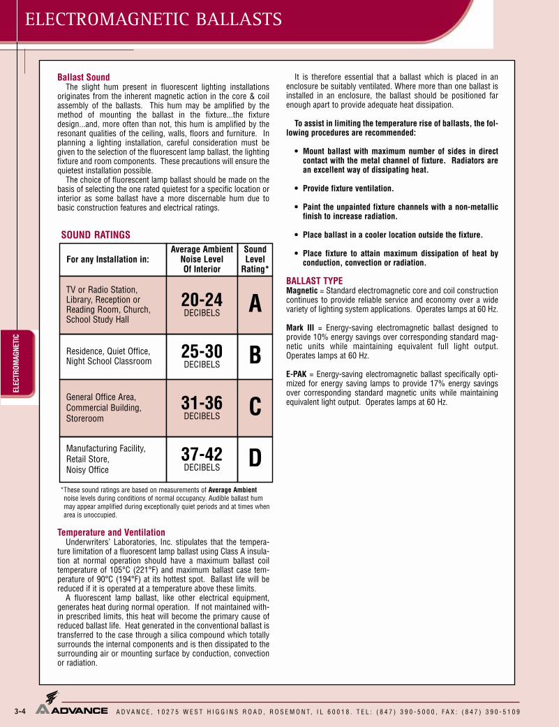
ELEC
TROM
AGNE
TIC
A D V A N C E , 1 0 2 7 5 W E S T H I G G I N S R O A D , R O S E M O N T, I L 6 0 0 1 8 . T E L : ( 8 4 7 ) 3 9 0 - 5 0 0 0 , F A X : ( 8 4 7 ) 3 9 0 - 5 1 0 9
ELECTROMAGNETIC BALLASTS
3-4
Ballast SoundThe slight hum present in fluorescent lighting installations
originates from the inherent magnetic action in the core & coilassembly of the ballasts. This hum may be amplified by themethod of mounting the ballast in the fixture...the fixturedesign...and, more often than not, this hum is amplified by theresonant qualities of the ceiling, walls, floors and furniture. Inplanning a lighting installation, careful consideration must begiven to the selection of the fluorescent lamp ballast, the lightingfixture and room components. These precautions will ensure thequietest installation possible.
The choice of fluorescent lamp ballast should be made on thebasis of selecting the one rated quietest for a specific location orinterior as some ballast have a more discernable hum due tobasic construction features and electrical ratings.
Temperature and VentilationUnderwriters’ Laboratories, Inc. stipulates that the tempera-
ture limitation of a fluorescent lamp ballast using Class A insula-tion at normal operation should have a maximum ballast coiltemperature of 105°C (221°F) and maximum ballast case tem-perature of 90°C (194°F) at its hottest spot. Ballast life will bereduced if it is operated at a temperature above these limits.
A fluorescent lamp ballast, like other electrical equipment,generates heat during normal operation. If not maintained with-in prescribed limits, this heat will become the primary cause ofreduced ballast life. Heat generated in the conventional ballast istransferred to the case through a silica compound which totallysurrounds the internal components and is then dissipated to thesurrounding air or mounting surface by conduction, convectionor radiation.
It is therefore essential that a ballast which is placed in anenclosure be suitably ventilated. Where more than one ballast isinstalled in an enclosure, the ballast should be positioned farenough apart to provide adequate heat dissipation.
To assist in limiting the temperature rise of ballasts, the fol-lowing procedures are recommended:
• Mount ballast with maximum number of sides in directcontact with the metal channel of fixture. Radiators arean excellent way of dissipating heat.
• Provide fixture ventilation.
• Paint the unpainted fixture channels with a non-metallicfinish to increase radiation.
• Place ballast in a cooler location outside the fixture.
• Place fixture to attain maximum dissipation of heat byconduction, convection or radiation.
BALLAST TYPEMagnetic = Standard electromagnetic core and coil constructioncontinues to provide reliable service and economy over a widevariety of lighting system applications. Operates lamps at 60 Hz.
Mark III = Energy-saving electromagnetic ballast designed toprovide 10% energy savings over corresponding standard mag-netic units while maintaining equivalent full light output.Operates lamps at 60 Hz.
E-PAK = Energy-saving electromagnetic ballast specifically opti-mized for energy saving lamps to provide 17% energy savingsover corresponding standard magnetic units while maintainingequivalent light output. Operates lamps at 60 Hz.
SOUND RATINGS
*These sound ratings are based on measurements of Average Ambientnoise levels during conditions of normal occupancy. Audible ballast hummay appear amplified during exceptionally quiet periods and at times whenarea is unoccupied.
For any Installation in:Average Ambient
Noise LevelOf Interior
SoundLevel
Rating*
TV or Radio Station,Library, Reception orReading Room, Church,School Study Hall
20-24DECIBELS A
Residence, Quiet Office,Night School Classroom
25-30DECIBELS B
General Office Area,Commercial Building,Storeroom
31-36DECIBELS C
Manufacturing Facility,Retail Store,Noisy Office
37-42DECIBELS D

3-5
T4 and T5HIGH POWER FACTOR SOUND RATED A
ELECTROMAGNETIC
RAPIDSTART
A D V A N C E , 1 0 2 7 5 W E S T H I G G I N S R O A D , R O S E M O N T, I L 6 0 0 1 8 . T E L : ( 8 4 7 ) 3 9 0 - 5 0 0 0 , F A X : ( 8 4 7 ) 3 9 0 - 5 1 0 9
Refer to pages 8-17 to 8-19 for lead lengths and shipping data
T8ELECTROMAGNETIC BALLASTSStraightRapid Start Lamps
120 R-1P817-TP ✓ ✓ 0.21 <20277 V-1P817-TP ✓ 0.10120 R-2P817-TP ✓ ✓ 0.40 <15277 V-2P817-TP ✓ 0.17
✓ ✓ 0.53 <15✓ 0.23
F17T8 (265mA)
1 17 50
2 17
24
47
1.01
0.96
T-2
T-2
F25T8 (265mA)
62 0.97T-2
1 25120
50 R-1P825-TP ✓ ✓ 0.28 31 0.94 <25
1 32120
50R-1P32-TP Mark III ✓ ✓ 0.32 35 0.95 <15
T-2277 V-1P32-TP Mark III ✓ ✓ 0.16 0.98347 G-1S32-TP Mark III ✓ 0.12 <15
2 32120 R-2P32-TP Mark III ✓ ✓ ✓ 0.61 71 0.99 <10
T-2277 V-2P32-TP Mark III ✓ ✓ ✓ 0.29 0.95347 G-2S32-TP Mark III ✓ ✓ 0.23 0.98 <15
26
45
1.04
0.98
<20
<20
0.95
0.980.94
0.96
30
62
0.91
0.96
<20
<20
4141
7776
0.98<15
<10
0.91
0.980.97
0.96
0.93
0.95
F40T8 (265mA)
1 40 50
2 40
52
87
1.02
0.87
T-2
T-2
120 R-1P840-TP ✓ ✓ 0.4550
<20
86
0.99277
0.88
V-1P840-TP ✓ 0.19 <20120 R-2P840-TP ✓ ✓ 0.73 <15277 V-2P840-TP ✓ 0.31 <15
0.960.950.990.99
50
50
50
DesignationLength (L)(inches)
Width (W)(inches)
Height (H)(inches)
Mounting (M)(inches)
T-2 9¹�₂ 2³�₈ 1¹�₂ 8²⁹�₃₂
DIMENSIONS
BLUEBLUE
WHITEBLK/WHTLINE
BALLAST
LAMP
Diag. 20
REDRED
Number
Min.StartingTemp.
(F)
InputVolts
CatalogNumber
Certifications LineCurrent(Amps)
InputPowerANSI
(Watts)
BallastFactor
THD%
PowerFactor
WiringDia.
Watts
Lamp Data
20
21
21
20
21
20
21
Dim.
0.97
0.920.91
0.97
F32T8 (265mA)
252
277 V-1P825-TP 0.12✓T-2 20
120 R-2P825-TP277 V-2P825-TP
50
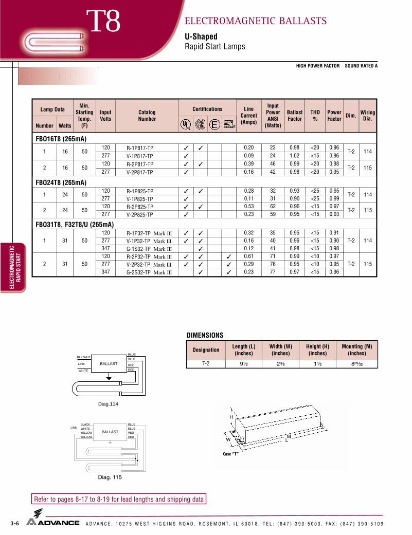
CENTIUM®
3-6
T5HOHIGH POWER FACTOR SOUND RATED A
ELEC
TROM
AGNE
TIC
RAPI
D ST
ART
A D V A N C E , 1 0 2 7 5 W E S T H I G G I N S R O A D , R O S E M O N T, I L 6 0 0 1 8 . T E L : ( 8 4 7 ) 3 9 0 - 5 0 0 0 , F A X : ( 8 4 7 ) 3 9 0 - 5 1 0 9
Refer to pages 8-17 to 8-19 for lead lengths and shipping data
T8 ELECTROMAGNETIC BALLASTSU-ShapedRapid Start Lamps
BLK/WHT
WHITE RED
RED
BLUE
BLUE
LINE BALLAST
Diag.114
DesignationLength (L)(inches)
Width (W)(inches)
Height (H)(inches)
Mounting (M)(inches)
T-2 9¹�₂ 2³�₈ 1¹�₂ 8²⁹�₃₂
DIMENSIONS
120 R-1P817-TP ✓ ✓ 0.20 <20277 V-1P817-TP ✓ 0.09120 R-2P817-TP ✓ ✓ 0.39 <20277 V-2P817-TP ✓ 0.16
277 V-1P825-TP ✓ 0.11120 R-2P825-TP ✓ ✓ 0.53 0.97277 V-2P825-TP ✓ 0.23
FBO16T8 (265mA)
1 16 50
2 16
23
46
0.98
0.99
T-2 114
T-2 115
FBO24T8 (265mA)
2 2462 0.96
T-2
1 24120
50 R-1P825-TP ✓ ✓ 0.28 32 0.93 0.95T-2
115
114
50
FBO31T8, F32T8/U (265mA)
1 31120
50R-1P32-TP Mark III ✓ ✓ 0.32 35 0.95 <15
T-2277 V-1P32-TP Mark III ✓ ✓ 0.16 0.96347 G-1S32-TP Mark III ✓ 0.12 <15
2 31120
50R-2P32-TP Mark III ✓ ✓ ✓ 0.61 71 0.99 <10
T-2
114
115277 V-2P32-TP Mark III ✓ ✓ ✓ 0.29 0.95347 G-2S32-TP Mark III ✓ ✓ 0.23 0.97 <15
24
42
1.02
0.98
<15
<20
0.96
0.980.96
0.95
31
59
0.90
0.95
0.99
0.93<15
<25<25
<15
4041
7776
0.98<15
<10
0.91
0.980.97
0.96
0.90
0.95
50
Number
Min.StartingTemp.
(F)
InputVolts
CatalogNumber
Certifications LineCurrent(Amps)
InputPowerANSI
(Watts)
BallastFactor
THD%
PowerFactor Dim. Wiring
Dia.Watts
Lamp Data

Lamp Data Min.StartingTemp.
(F)
InputVolts
CatalogNumber
Certifications LineCurrent(Amps)
InputPowerANSI
(Watts)
BallastFactor
THD%
PowerFactor Dim. Wiring
Dia.Number Watts
F40T10 (420mA)
1 40 50
120 R-140-TP Mark III R ✓ ✓ ✓ ✓ 0.46 53 0.95 <15 0.96T-2
220 X-140-TP ✓ 0.25 54 0.95 <10 0.98
240 YHQM-1P40-TP ✓ 0.23 52 0.80 <15 0.94 R-5 20
277 V-140-TP Mark III R ✓ ✓ ✓ ✓ 0.20 53 0.95 <10 0.96T-2
347 G-140-TP Mark III R ✓ ✓ 0.16 53 0.95 <15 0.95
2 40 50
120 R-2S40-TP Mark III R ✓ ✓ ✓ ✓ 0.75 88 0.95 <20 0.98
T-2 21
220 XQM-2S40-TP ✓ ✓ 0.45 96 0.95 <25 0.97
240 YQM-2S40-TP ● ✓ ✓ 0.42 98 0.95 <25 0.97
277 V-2S40-TP Mark III R ✓ ✓ ✓ ✓ 0.33 88 0.95 <25 0.96
347 G-2S40-TP Mark III R ✓ ✓ 0.27 88 0.95 <20 0.94
3-7
T4 and T5HIGH POWER FACTOR SOUND RATED A
ELECTROMAGNETIC
RAPIDSTART
A D V A N C E , 1 0 2 7 5 W E S T H I G G I N S R O A D , R O S E M O N T, I L 6 0 0 1 8 . T E L : ( 8 4 7 ) 3 9 0 - 5 0 0 0 , F A X : ( 8 4 7 ) 3 9 0 - 5 1 0 9
Refer to pages 8-17 to 8-19 for lead lengths and shipping data
T10ELECTROMAGNETIC BALLASTSStraightRapid Start Lamps
Case “R”
MLW
HBLUEBLUE
WHITEBLK/WHTLINE
BALLAST
LAMP
Diag. 20
REDRED
● Sound Rated BR For Replacement Use Only
DesignationLength (L)(inches)
Width (W)(inches)
Height (H)(inches)
Mounting (M)(inches)
R-5 9¹�₂ 2³�₈ 1¹¹�₁₆ 8²⁹�₃₂
T-2 9¹�₂ 2³�₈ 1¹�₂ 8²⁹�₃₂
DIMENSIONS

Lamp Data Min.StartingTemp.
(F)
InputVolts
CatalogNumber
Certifications LineCurrent(Amps)
InputPowerANSI
(Watts)
BallastFactor
THD%
PowerFactor Dim. Wiring
Dia.Number Watts
F25T12 (455mA)
1 25 60120 HM-1P30-TP ✓ ✓ 0.34 40 0.91 <20 0.98
T-2 20277 VM-1P30-TP ✓ 0.15 40 0.94 <15 0.96
2 25 60120
RM-2SP30-TP ✓ ✓ 0.58 70 0.90 <10 0.99
T-2 21R-2SP30-TP Mark III ✓ ✓ 0.55 65 0.91 <15 0.98
277VM-2SP30-TP ✓ 0.26 70 0.93 <10 0.97
V-2SP30-TP Mark III ✓ 0.24 65 0.91 <15 0.98
F30T12 (430mA)
1 30 50120
RL-140-TP ❉❖ ✓ ✓ 0.60 33 0.71 <10 0.46 R-4 16HM-1P30-TP ✓ ✓ 0.40 47 0.96 <20 0.98 T-2
240 YHQM-1P40-TP ✓ 0.18 43 0.82 <10 0.99 R-5 20277 VM-1P30-TP ✓ 0.18 49 0.99 <15 0.98 T-2
2 30 50120
RM-2SP30-TP ✓ ✓ 0.66 79 0.97 <10 0.99
T-2 21R-2S030-TP Mark III ✓ ✓ 0.63 75 0.96 <15 0.99
277VM-2SP30-TP ✓ 0.29 81 0.97 <10 0.99
V-2SP30-TP Mark III ✓ 0.27 74 0.95 <10 0.99
HIGH POWER FACTOR SOUND RATED A
3-8
T12EL
ECTR
OMAG
NETI
CRA
PID
STAR
TELECTROMAGNETIC BALLASTSStraightRapid Start Lamps
A D V A N C E , 1 0 2 7 5 W E S T H I G G I N S R O A D , R O S E M O N T, I L 6 0 0 1 8 . T E L : ( 8 4 7 ) 3 9 0 - 5 0 0 0 , F A X : ( 8 4 7 ) 3 9 0 - 5 1 0 9
Refer to pages 8-17 to 8-19 for lead lengths and shipping data
DesignationLength (L)(inches)
Width (W)(inches)
Height (H)(inches)
Mounting (M)(inches)
R-4 6¹�₂ 1¹⁵�₁₆ 1³�₈ 6+
R-5 9¹�₂ 2³�₈ 1¹¹�₁₆ 8²⁹�₃₂
T-2 9¹�₂ 2³�₈ 1¹�₂ 8²⁹�₃₂
+ Mounting dimensions refer to slots only
DIMENSIONS
BALLASTBLACK
Diag. 16
LINE
LAMP
WHITERED
REDBLUE
WHITE
CIRCUIT INTERRUPTINGLAMPHOLDER
Case “R”
MLW
H
BLUEBLUE
WHITEBLK/WHTLINE
BALLAST
LAMP
Diag. 20
REDRED
BLK/WHT
❉ Normal Power Factor ❖ Requires Circuit-Interrupting Lamp Holders

3-9
T12HIGH POWER FACTOR SOUND RATED A
ELECTROMAGNETIC
RAPIDSTART
ELECTROMAGNETIC BALLASTSStraightRapid Start Lamps
A D V A N C E , 1 0 2 7 5 W E S T H I G G I N S R O A D , R O S E M O N T, I L 6 0 0 1 8 . T E L : ( 8 4 7 ) 3 9 0 - 5 0 0 0 , F A X : ( 8 4 7 ) 3 9 0 - 5 1 0 9
Refer to pages 8-17 to 8-19 for lead lengths and shipping data
Diag. 25
BALLAST
LAMP
8
7654
21
3
YEL
RED
LAMP
LAMP
LAMP
BLU
YELRED
BLUBLK / WHT
WHT
10
9
11
12
13
14
15
16
BLKBLUBLUREDREDYELYEL
OUTBOARD LAMPS
INBOARD LAMPS
WHT / BLU
BALLAST
LAMP
LAMP
LAMP
Diag. 30
BLUEBLUE
YELLOWYELLOW
REDRED
BLUE/WHITE
BLACKWHITELINE
BLUE/WHITE
H
W M
L
Case “D2”
Diag. 25
BLUEBLUE
WHITEBLK/WHTLINE
BALLAST
LAMP
Diag. 20
REDRED
● Sound Rated B ❉ Normal Power Factor✪ For Residential Use Only R For Replacement Use Only
DesignationLength (L)(inches)
Width (W)(inches)
Height (H)(inches)
Mounting (M)(inches)
D-2 17 2³�₈ 1¹�₂ 16⁵�₁₆
T-2 9¹�₂ 2³�₈ 1¹�₂ 8²⁹�₃₂
DIMENSIONS
Lamp Data Min.StartingTemp.
(F)
InputVolts
CatalogNumber
Certifications LineCurrent(Amps)
InputPowerANSI
(Watts)
BallastFactor
THD%
PowerFactor Dim. Wiring
Dia.Number Watts
F34T12 (460mA)
1 34 60
120 R-140-TP Mark III R ✓ ✓ ✓ ✓ 0.38 43 0.88 <15 0.94
T-2 20220 X-140-TP ✓ 0.20 44 0.89 <10 0.99277 V-140-TP Mark III R ✓ ✓ ✓ ✓ 0.16 43 0.88 <10 0.97347 G-140-TP Mark III R ✓ ✓ 0.13 43 0.88 <15 0.95
2 34 60
120RM-2S35-TP ✪ ❉ ✓ 0.61 60 0.66 <20 0.82
T-2 21
R-2S34-TP E-PAK R ✓ ✓ ✓ ✓ 0.57 68 0.87 <15 0.99R-2S40-TP Mark III R ✓ ✓ ✓ ✓ 0.63 72 0.88 <15 0.95
220 XQM-2S40-TP ✓ ✓ 0.36 78 0.92 <20 0.98240 YQM-2S40-TP ✓ ✓ 0.35 84 0.92 <25 0.99
277V-2S34-TP E-PAK R ✓ ✓ ✓ ✓ 0.25 68 0.87 <15 0.98
V-2S40-TP Mark III R ✓ ✓ ✓ ✓ 0.27 72 0.88 <20 0.96347 G-2S40-TP Mark III R ✓ ✓ 0.22 72 0.88 <20 0.94
3 34 60120 R-3S34-TP E-PAK ✓ ✓ 0.88 103 0.88 <20 0.97
T-2 30277 V-3S34-TP E-PAK ✓ ✓ 0.37 103 0.88 <20 0.99
4 34 60 120 R-4S40-A-TP-AC Mark III ✓ ✓ ✓ ✓ 1.26 144 0.88 <20 0.95 D-2 25

Lamp Data Min.StartingTemp.
(F)
InputVolts
CatalogNumber
Certifications LineCurrent(Amps)
InputPowerANSI
(Watts)
BallastFactor
THD%
PowerFactor Dim. Wiring
Dia.Number Watts
F40T12 (430mA)R-140-TP Mark III R ✓ ✓ ✓ ✓ 0.43 50 0.95 <10 0.97 T-2 20
RL-140-TP ✪❖❉ ✓ ✓ 0.53 32 0.63 <15 0.50 R-4 16
220 X-140-TP ✓ 0.23 51 0.94 <10 0.99 T-2
240 YHQM-1P40-TP ✓ 0.21 49 0.78 <15 0.97 R-5
277 V-140-TP Mark III R ✓ ✓ ✓ ✓ 0.19 50 0.95 <10 0.95
347 G-140-TP Mark III R ✓ ✓ 0.15 50 0.95 <15 0.96
2 40 50
120
RM-2S35-TP ✪ ❉ ✓ 0.72 70 0.68 <20 0.81
T-2 21
R-2S34-TP E-Pak R ✓ ✓ ✓ 0.67 79 0/86 <15 0.98
R-2S40-TP Mark III R ✓ ✓ ✓ ✓ 0.73 86 0.95 <15 0.98
220 XQM-2S40-TP ✓ ✓ 0.43 93 0.97 <25 0.98
240 YQM-2S40-TP ● ✓ ✓ 0.42 98 0.99 <25 0.97
277V-2S34-TP E-Pak R ✓ ✓ ✓ ✓ 0.30 79 0.86 <15 0.95
V-2S40-TP Mark III R ✓ ✓ ✓ ✓ 0.32 86 0.95 <20 0.97
347 G-2S40-TP Mark III R ✓ ✓ 0.27 86 0.95 <20 0.92 T-2 21
4 40 50 120 R-4S40-A-TP-AC Mark III ✓ ✓ ✓ ✓ 1.46 172 0.95 <20 0.98 D-2 25
3-10
T12HIGH POWER FACTOR SOUND RATED A
ELEC
TROM
AGNE
TIC
RAPI
D ST
ART
ELECTROMAGNETIC BALLASTSStraightRapid Start Lamps
A D V A N C E , 1 0 2 7 5 W E S T H I G G I N S R O A D , R O S E M O N T, I L 6 0 0 1 8 . T E L : ( 8 4 7 ) 3 9 0 - 5 0 0 0 , F A X : ( 8 4 7 ) 3 9 0 - 5 1 0 9
Refer to pages 8-17 to 8-19 for lead lengths and shipping data
DesignationLength (L)(inches)
Width (W)(inches)
Height (H)(inches)
Mounting (M)(inches)
R-4 6¹�₂ 1¹⁵�₁₆ 1³�₈ 6+
R-5 9¹�₂ 2³�₈ 1¹¹�₁₆ 8²⁹�₃₂
T-2 9¹�₂ 2³�₈ 1¹�₂ 8²⁹�₃₂
D-2 17 2³⁄₈ 1¹⁄₂ 16⁵⁄₁₆
+ Mounting dimensions refer to slots onlyBALLAST
BLACK
Diag. 16
LINE
LAMP
WHITERED
REDBLUE
WHITE
CIRCUIT INTERRUPTINGLAMPHOLDER
Case “R”
MLW
HBLUEBLUE
WHITEBLK/WHTLINE
BALLAST
LAMP
Diag. 20
REDRED
DIMENSIONS● Sound Rated B ✪ For Residential Use Only ❉ Normal Power Factor ❖ Requires Circuit-Interrupting Lamp HoldersR For Replacement Use Only
BLK/WHT
H
W M
L
Case “D2”
Diag. 25
BALLAST
LAMP
8
7654
21
3
YEL
RED
LAMP
LAMP
LAMP
BLU
YELRED
BLUBLK / WHT
WHT
10
9
11
12
13
14
15
16
BLKBLUBLUREDREDYELYEL
OUTBOARD LAMPS
INBOARD LAMPS
WHT / BLU
Diag. 25
T-2
20
1 40 50
120
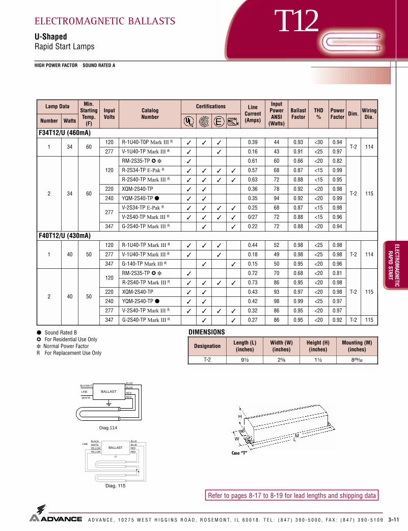
Lamp Data Min.StartingTemp.
(F)
InputVolts
CatalogNumber
Certifications LineCurrent(Amps)
InputPowerANSI
(Watts)
BallastFactor
THD%
PowerFactor Dim. Wiring
Dia.Number Watts
F34T12/U (460mA)
1 34 60120 R-1U40-T0P Mark III R ✓ ✓ ✓ 0.39 44 0.93 <30 0.94
T-2 114277 V-1U40-TP Mark III R ✓ ✓ 0.16 43 0.91 <25 0.97
2 34 60
120
RM-2S35-TP ✪ ❉ ✓ 0.61 60 0.66 <20 0.82
T-2 115
R-2S34-TP E-Pak R ✓ ✓ ✓ ✓ 0.57 68 0.87 <15 0.99
R-2S40-TP Mark III R ✓ ✓ ✓ ✓ 0.63 72 0.88 <15 0.95
220 XQM-2S40-TP ✓ ✓ 0.36 78 0.92 <20 0.98
240 YQM-2S40-TP ● ✓ ✓ 0.35 94 0.92 <20 0.99
277V-2S34-TP E-Pak R ✓ ✓ ✓ ✓ 0.25 68 0.87 <15 0.98
V-2S40-TP Mark III R ✓ ✓ ✓ ✓ 0/27 72 0.88 <15 0.96
347 G-2S40-TP Mark III R ✓ ✓ 0.22 72 0.88 <20 0.94
F40T12/U (430mA)
1 40 50
120 R-1U40-TP Mark III R ✓ ✓ ✓ 0.44 52 0.98 <25 0.98
T-2 114277 V-1U40-TP Mark III R ✓ ✓ 0.18 49 0.98 <25 0.98
347 G-140-TP Mark III R ✓ ✓ 0.15 50 0.95 <20 0.96
2 40 50
120RM-2S35-TP ✪ ❉ ✓ 0.72 70 0.68 <20 0.81
T-2 115
R-2S40-TP Mark III R ✓ ✓ ✓ ✓ 0.73 86 0.95 <20 0.98
220 XQM-2S40-TP ✓ ✓ 0.43 93 0.97 <20 0.98
240 YQM-2S40-TP ● ✓ ✓ 0.42 98 0.99 <25 0.97
277 V-2S40-TP Mark III R ✓ ✓ ✓ ✓ 0.32 86 0.95 <20 0.97
347 G-2S40-TP Mark III R ✓ ✓ 0.27 86 0.95 <20 0.92 T-2 115
3-11
T12HIGH POWER FACTOR SOUND RATED A
ELECTROMAGNETIC
RAPIDSTART
ELECTROMAGNETIC BALLASTSU-ShapedRapid Start Lamps
A D V A N C E , 1 0 2 7 5 W E S T H I G G I N S R O A D , R O S E M O N T, I L 6 0 0 1 8 . T E L : ( 8 4 7 ) 3 9 0 - 5 0 0 0 , F A X : ( 8 4 7 ) 3 9 0 - 5 1 0 9
Refer to pages 8-17 to 8-19 for lead lengths and shipping data
BLK/WHT
WHITE RED
RED
BLUE
BLUE
LINE BALLAST
Diag.114
● Sound Rated B✪ For Residential Use Only❉ Normal Power FactorR For Replacement Use Only
DesignationLength (L)(inches)
Width (W)(inches)
Height (H)(inches)
Mounting (M)(inches)
T-2 9¹�₂ 2³�₈ 1¹�₂ 8²⁹�₃₂
DIMENSIONS
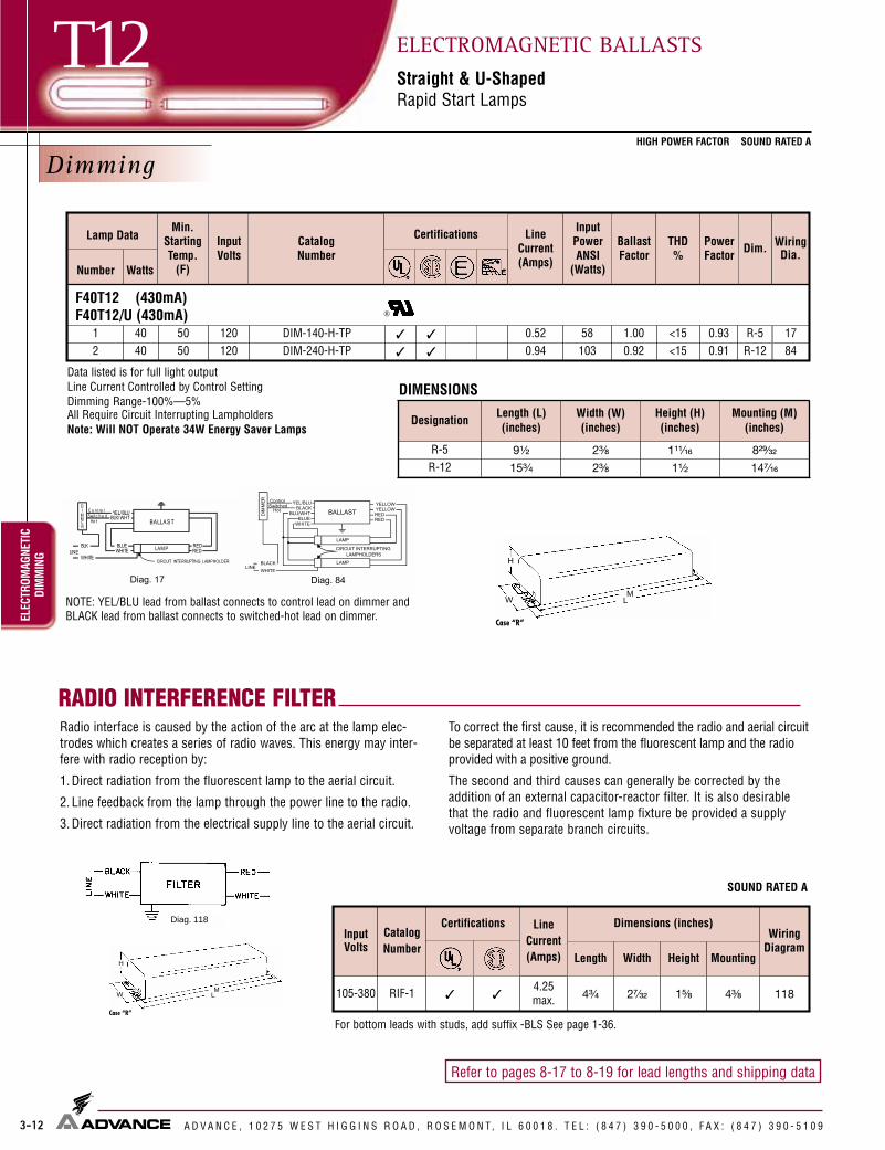
Dimming
3-12
T12HIGH POWER FACTOR SOUND RATED A
ELEC
TROM
AGNE
TIC
DIM
MIN
GELECTROMAGNETIC BALLASTSStraight & U-ShapedRapid Start Lamps
A D V A N C E , 1 0 2 7 5 W E S T H I G G I N S R O A D , R O S E M O N T, I L 6 0 0 1 8 . T E L : ( 8 4 7 ) 3 9 0 - 5 0 0 0 , F A X : ( 8 4 7 ) 3 9 0 - 5 1 0 9
Refer to pages 8-17 to 8-19 for lead lengths and shipping data
RADIO INTERFERENCE FILTER
Case “R”
MLW
H
Radio interface is caused by the action of the arc at the lamp elec-trodes which creates a series of radio waves. This energy may inter-fere with radio reception by:
1. Direct radiation from the fluorescent lamp to the aerial circuit.
2. Line feedback from the lamp through the power line to the radio.
3. Direct radiation from the electrical supply line to the aerial circuit.
To correct the first cause, it is recommended the radio and aerial circuitbe separated at least 10 feet from the fluorescent lamp and the radioprovided with a positive ground.
The second and third causes can generally be corrected by theaddition of an external capacitor-reactor filter. It is also desirablethat the radio and fluorescent lamp fixture be provided a supplyvoltage from separate branch circuits.
DesignationLength (L)(inches)
Width (W)(inches)
Height (H)(inches)
Mounting (M)(inches)
R-5 9¹�₂ 2³�₈ 1¹¹�₁₆ 8²⁹�₃₂
R-12 15³�₄ 2³�₈ 1¹�₂ 14⁷�₁₆
DIMENSIONS
DIM-140-H-TP ✓ 0.52 58 1.00 R-5DIM-240-H-TP ✓ 0.94 103 0.92 R-12
1784
1 40 120120
5050
<15<15
0.930.912 40
F40T12 (430mA)F40T12/U (430mA)
✓
✓
InputVolts
CatalogNumber
LineCurrent(Amps)
WiringDiagram
105-380 RIF-1 4.25max. 1184³�₄
Dimensions (inches)Certifications
2⁷�₃₂✓ ✓ 1⁵�₈ 4³�₈
Length Width Height Mounting
Data listed is for full light outputLine Current Controlled by Control SettingDimming Range-100%—5%All Require Circuit Interrupting LampholdersNote: Will NOT Operate 34W Energy Saver Lamps
For bottom leads with studs, add suffix -BLS See page 1-36.
Diag. 118
SOUND RATED A
Min.StartingTemp.
(F)
InputVolts
CatalogNumber
Certifications LineCurrent(Amps)
InputPowerANSI
(Watts)
BallastFactor
THD%
PowerFactor Dim. Wiring
Dia.WattsNumber
Lamp Data
NOTE: YEL/BLU lead from ballast connects to control lead on dimmer andBLACK lead from ballast connects to switched-hot lead on dimmer.
Case “R”
MLW
H

3-13
T12/HOHIGH POWER FACTOR SOUND RATED C
ELECTROMAGNETIC
HIGHOUTPUT
ELECTROMAGNETIC BALLASTSHigh OutputRapid Start Lamps
A D V A N C E , 1 0 2 7 5 W E S T H I G G I N S R O A D , R O S E M O N T, I L 6 0 0 1 8 . T E L : ( 8 4 7 ) 3 9 0 - 5 0 0 0 , F A X : ( 8 4 7 ) 3 9 0 - 5 1 0 9
Refer to pages 8-17 to 8-19 for lead lengths and shipping data
BALLAST
LAMP 1
LAMP 2
LAMP 3
LAMP 4
Diag. 13
BLUE
BLUE
BLUE-WH
BLUE-WH
RED
RED
BLACK
WHITE
YELLOW
YELLOW
BROWN
BROWN
LINE BALLAST
LAMP 1
LAMP 2
LAMP 3
Diag. 8
BLUE
BLUE
BLUE-WH
BLUE-WH
RED
RED
BLACK
WHITE
YELLOW
YELLOW
BROWN
BROWN
LINE
Note: Insulate unused leads individually as shown on ballast label
Diag. 13
BLUEBLUE
WHITEBLK/WHTLINE
BALLAST
LAMP
Diag. 20
REDRED
BLACKLINE
LAMP
LAMP
YELLOWYELLOW RED
RED
BLUEBLUE
BLACK BALLAST
DIAG. 125
Diag. 8
Note: Insulate unused leads individually asshown on ballast label.
RS-110-TP ● ✓ ✓ 0.58 63 0.93R-9
VS-110-TP ● ✓ ✓ 0.30 66 0.93120
R-9
F24T12/HO (800mA)
1 35<50<50
-20
-20
120
352
277
RC-2S85-TP ✓ ✓ 1.01 95 0.80 <45240 YS-2S85-TP ✓ ✓ 0.55 92 0.79 <50277 VC-2S85-TP ✓ ✓ 0.48 94 0.80 <50
3 35 120-20 RC-4S60-TP ■ ✓ ✓ 1.60 148 0.94 <35 R-94 35 120-20 RC-4S60-TP ■ ✓ ✓ 1.80 183 1.00 <30 R-9
F36T12/HO (800mA)
1 50120
-20RS-110-TP ● ✓ ✓ 0.62 71 0.94 <40
R-9277 VS-110-TP ● ✓ ✓ 0.31 74 0.94 <45
2 50120
-20RC-2S85-TP ✓ ✓ 1.00 107 0.82 <35
240 YS-2S85-TP ✓ ✓ 0.53 103 0.80 <35277 VC-2S85-TP ✓ ✓ 0.47 105 0.82 <35
R-9
3 50 120-20 RC-4S60-TP ■ ✓ ✓ 1.60 166 0.93 <30 R-94 50 120-20 RC-4S60-TP ■ ✓ ✓ 1.90 212 0.98 <20 R-9
F30T12/HO (800mA)
0.900.800.780.700.710.770.85
0.95
0.860.900.810.800.860.93
20
21
21813
20
21
21
813
125
125
DesignationLength (L)(inches)
Width (W)(inches)
Height (H)(inches)
Mounting (M)(inches)
R-9 11³�₄ 3³�₁₆ 2⁵�₈ 11⁹�₆₄
DIMENSIONS● Sound Rated B■ Sound Rated D
Number
Min.StartingTemp.
(F)
InputVolts
CatalogNumber
Certifications LineCurrent(Amps)
InputPowerANSI
(Watts)
BallastFactor
THD%
PowerFactor Dim. Wiring
Dia.Watts
Lamp Data
1 50120
-20RS-110-TP ● ✓ ✓ 0.61 67 0.93 <45
R-9277 VS-110-TP ● ✓ ✓ 0.30 70 0.93 <45
0.91
0.8420
2 50120
-20RC-2S85-TP ✓ ✓ 0.96 98 0.80 <35
R-9277 VC-2S85-TP ✓ ✓ 0.45 96 0.80 <35
0.85
0.7721
Case “R”
MLW
H

BALLAST
LAMP 1
LAMP 2
LAMP 3
Diag. 8
BLUE
BLUE
BLUE-WH
BLUE-WH
RED
RED
BLACK
WHITE
YELLOW
YELLOW
BROWN
BROWN
LINE
Note: Insulate unused leads individually as shown on ballast labelNote: insulate unused leads individually asshown on ballast label
Diag. 8
3-14
T12/HOHIGH POWER FACTOR SOUND RATED C
ELEC
TROM
AGNE
TIC
HIGH
OUTP
UTELECTROMAGNETIC BALLASTSHigh OutputRapid Start Lamps
A D V A N C E , 1 0 2 7 5 W E S T H I G G I N S R O A D , R O S E M O N T, I L 6 0 0 1 8 . T E L : ( 8 4 7 ) 3 9 0 - 5 0 0 0 , F A X : ( 8 4 7 ) 3 9 0 - 5 1 0 9
Refer to pages 8-17 to 8-19 for lead lengths and shipping data
DesignationLength (L)(inches)
Width (W)(inches)
Height (H)(inches)
Mounting (M)(inches)
R-9 11³�₄ 3³�₁₆ 2⁵�₈ 11⁹�₆₄
R-11 14⁵�₁₆ 3³�₁₆ 2⁵�₈ 13³�₄
Min.StartingTemp.
(F)
InputVolts
CatalogNumber
Certifications LineCurrent(Amps)
InputPowerANSI
(Watts)
BallastFactor
THD%
PowerFactor Dim. Wiring
Dia.WattsNumber
Lamp Data
RS-110-TP ● ✓ ✓ 0.72 84 0.94 <35
R-9RC-2S85-TP ✓ ✓ 0.91 79 0.78 <50
240 YS-2S85-TP ✓ ✓ 0.53 82 0.80 <50
VS-110-TP ● ✓ ✓ 0.34 86 0.96 <35
VC-2S85-TP ✓ ✓ 0.46 80 0.78 <50
-20RC-2S85-TP ✓ ✓ 1.16 133 0.85 <20
240 YS-2S85-TP ✓ ✓ 0.60 131 0.84 <25
VC-2S85-TP ✓ ✓ 0.53 131 0.85 <20R-9
-20RC-4S60-TP ■ ✓ ✓ 1.90 217 0.92 <20 R-9
RC-4S85-TP ■ ✓ ✓ 1.70 190 0.86 <10 R-11
-20 RC-4S60-TP ■ ✓ ✓ 2.40 288 0.92 <15
RC-4S85-TP ■ ✓ ✓ 1.99 237 0.81 <15
0.970.720.64
0.91
0.630.960.910.900.950.930.990.99
R-9R-11
F48T12/HO (800mA)
1
2
3
4
60
60
60
60
120
277
120
277
120
120
-20
2039126
20
39
21
21
891313
125
DIMENSIONS● Sound Rated B■ Sound Rated D
R-9
F42T12/HO (800mA)
2 55120
-20RC-2S85-TP ✓ ✓ 1.12 126 0.85 <30
240 YS-2S85-TP ✓ ✓ 0.58 119 0.83 <30277 VC-2S85-TP ✓ ✓ 0.51 124 0.85 <30
0.940.860.88
21
21125
1 55120
-20RS-110-TP ● ✓ ✓ 0.69 80 0.96 <40
R-9277 VS-110-TP ● ✓ ✓ 0.33 81 0.96 <40
0.97
0.8820
BALLAST
LAMP
Diag. 39
*FOR SINGLE LAMP OPERATION, INSULATEYELLOW LEADS INDIVIDUALLY FOR 600V
WHITEBLACK
YEL
YEL
LINE
**
BLUEBLUEREDRED
BALLAST
LAMP 1
LAMP 2
LAMP 3
LAMP 4
Diag. 13
BLUE
BLUE
BLUE-WH
BLUE-WH
RED
RED
BLACK
WHITE
YELLOW
YELLOW
BROWN
BROWN
LINE
BLUEBLUE
WHITEBLK/WHTLINE
BALLAST
LAMP
Diag. 20
REDRED
BLACKLINE
LAMP
LAMP
YELLOWYELLOW RED
RED
BLUEBLUE
BLACK BALLAST
LAMP
BALLASTBLUEBLUEREDRED
YELYEL
BLACKBLACK
LINE
*FOR SINGLE LAMP OPERATION INSULATEYELLOW LEADS INDIVIDUALLY FOR 600V
**
DIAG. 126Diag 125
BALLAST
LAMP 2
LAMP 3
LAMP 4
Diag. 9
BLUE
BLUE
BLUE-WH
BLUE-WH
RED
RED
BLACK
WHITE
YELLOW
YELLOW
BROWN
BROWN
LINE
Note: Insulate unused leads individually as shown on ballast labelNote: insulate unused leads individually as shown on ballast label
Diag. 9
Diag. 13
Case “R”
MLW
H

3-15
T12/HOHIGH POWER FACTOR SOUND RATED C
ELECTROMAGNETIC
HIGHOUTPUT
ELECTROMAGNETIC BALLASTSHigh OutputRapid Start Lamps
A D V A N C E , 1 0 2 7 5 W E S T H I G G I N S R O A D , R O S E M O N T, I L 6 0 0 1 8 . T E L : ( 8 4 7 ) 3 9 0 - 5 0 0 0 , F A X : ( 8 4 7 ) 3 9 0 - 5 1 0 9
Refer to pages 8-17 to 8-19 for lead lengths and shipping data
DesignationLength (L)(inches)
Width (W)(inches)
Height (H)(inches)
Mounting (M)(inches)
R-9 11³�₄ 3³�₁₆ 2⁵�₈ 11⁹�₆₄
R-11 14⁵�₁₆ 3³�₁₆ 2⁵�₈ 13³�₄
DIMENSIONS
YS-2S85-TP ✓ ✓ 0.54 89 0.79 <40240
VS-110-TP ● ✓ ✓ 0.38 98 0.96 <35
VC-2S85-TP ✓ ✓ 0.48 87 0.80 <40120 RC-2S85-TP ✓ ✓ 1.50 178 0.90 <15240 YS-2S85-TP ✓ ✓ 0.75 166 0.89 <20277 VC-2S85-TP ✓ ✓ 0.65 170 0.86 <20
3 75 120 RC-4S85-TP ■ ✓ ✓ 1.90 223 0.83 <20 R-11 94 75 120 RC-4S85-TP ■ ✓ ✓ 2.35 278 0.80 <15 R-11 13
F60T12/HO (800mA)
2 75
277
-20 R-9
2 80
277
-20 R-9
YS-2S85-TP ✓ ✓ 0.56 97 0.80 <40240
VS-110-TP ● ✓ ✓ 0.42 106 0.96 <35
VC-2S85-TP ✓ ✓ 0.47 95 0.78 <40120 RC-2S85-TP ✓ ✓ 1.50 178 0.90 <15240 YS-2S85-TP ✓ ✓ 0.75 166 0.89 <20277 VC-2S85-TP ✓ ✓ 0.65 170 0.86 <20
3 80 120 RC-4S85-TP ■ ✓ ✓ 2.09 246 0.84 <15 R-11 94 80 120 RC-4S85-TP ■ ✓ ✓ 2.64 312 0.78 <10
0.690.930.660.990.920.940.980.99
0.720.910.730.990.920.940.980.98 R-11 13
F64T12/HO (800mA)
39
12620
21
21125
2139
12620
21125
-20-20
-20-20
● Sound Rated B■ Sound Rated D
Min.StartingTemp.
(F)
InputVolts
CatalogNumber
Certifications LineCurrent(Amps)
InputPowerANSI
(Watts)
BallastFactor
THD%
PowerFactor Dim. Wiring
Dia.WattsNumber
Lamp Data
-20
RS-110-TP ● ✓ ✓ 0.88 104 0.96 <35
RC-2S85-TP ✓ ✓ 0.94 90 0.77 <401 80
120
R-9
0.980.80
2039
BALLAST
LAMP
Diag. 39
*FOR SINGLE LAMP OPERATION, INSULATEYELLOW LEADS INDIVIDUALLY FOR 600V
WHITEBLACK
YEL
YEL
LINE
**
BLUEBLUEREDRED
BALLAST
LAMP 1
LAMP 2
LAMP 3
LAMP 4
Diag. 13
BLUE
BLUE
BLUE-WH
BLUE-WH
RED
RED
BLACK
WHITE
YELLOW
YELLOW
BROWN
BROWN
LINE
BLUEBLUE
WHITEBLK/WHTINE
BALLAST
LAMP
Diag. 20
REDRED
BLACKLINE
LAMP
LAMP
YELLOWYELLOW RED
RED
BLUEBLUE
BLACK BALLASTLAMP
BALLASTBLUEBLUEREDRED
YELYEL
BLACKBLACK
LINE
*FOR SINGLE LAMP OPERATION INSULATEYELLOW LEADS INDIVIDUALLY FOR 600V
**
DIAG. 126
Case “R”
MLW
H
Diag 125
BALLAST
LAMP 2
LAMP 3
LAMP 4
Diag. 9
BLUE
BLUE
BLUE-WH
BLUE-WH
RED
RED
BLACK
WHITE
YELLOW
YELLOW
BROWN
BROWN
LINE
Note: Insulate unused leads individually as shown on ballast labelNote: insulate unused leads individually as shown on ballast label
Diag. 9
Diag. 13
-20
RS-110-TP ● ✓ ✓ 0.83 97 0.93 <35
RC-2S85-TP ✓ ✓ 0.94 90 0.77 <401 75
120
R-9
0.970.80
2039

3-16
T12/HOHIGH POWER FACTOR SOUND RATED C
ELEC
TROM
AGNE
TIC
HIGH
OUT
PUT
ELECTROMAGNETIC BALLASTSHigh OutputRapid Start Lamps
A D V A N C E , 1 0 2 7 5 W E S T H I G G I N S R O A D , R O S E M O N T, I L 6 0 0 1 8 . T E L : ( 8 4 7 ) 3 9 0 - 5 0 0 0 , F A X : ( 8 4 7 ) 3 9 0 - 5 1 0 9
Refer to pages 8-17 to 8-19 for lead lengths and shipping data
BALLAST
LAMP
Diag. 39
*FOR SINGLE LAMP OPERATION, INSULATEYELLOW LEADS INDIVIDUALLY FOR 600V
WHITEBLACK
YEL
YEL
LINE
**
BLUEBLUEREDRED
DesignationLength (L)(inches)
Width (W)(inches)
Height (H)(inches)
Mounting (M)(inches)
R-9 11³�₄ 3³�₁₆ 2⁵�₈ 11⁹�₆₄
R-11 14⁵�₁₆ 3³�₁₆ 2⁵�₈ 13³�₄
RC-2S85-TP ✓ ✓ 0.98 100 0.82 <35
RS-110-TP ● ✓ ✓ 0.96 113 0.98 <30240 YS-2S85-TP ✓ ✓ 0.53 99 0.83 <35
VC-2S85-TP ✓ ✓ 0.47 99 0.81 <35
VS-110-TP ● ✓ ✓ 0.44 116 0.99 <30
39201263920
RC-2S85-TP ✓ ✓ 1.54 184 0.91 <15
R-2S110-TP Mark III ✓ ✓ 1.60 193 0.95 <15
50YS-2S85-TP ✓ ✓ 0.75 173 0.89 <20
YS-2S110-TP ✓ 0.88 203 0.99 <15
VC-2S85-TP ✓ ✓ 0.67 180 0.90 <20
V-2S110-TP Mark III ✓ ✓ 0.75 201 0.98 <20
RC-4S60-TP ■ ✓ ✓ 2.40 291 0.90 <15 R-9
RC-4S85-TP ■ ✓ ✓ 2.17 256 0.81 R-1189
4 85 120-20 RC-4S85-TP ■ ✓ ✓ 2.73 323 0.75 <10 R-11 13
RC-2S85-TP ✓ 1.03 113 0.83 <30
VC-2S85-TP ✓ 0.47 0.81 <35
RC-2S85-TP ✓ 1.76 209 0.90 <15
VC-2S85-TP ✓ 0.73 0.89 <20
F72T12/HO (800mA)
1
3
1
2
85
85
100
100
120
277
120
120
120
-20
-20
-20 R-9 39
F84T12/HO (800mA)
G-2S110-TP Mark III ✓ 0.57 193 0.94 <20
277
27750
104
198
21
125
<15
0.850.980.780.760.950.990.990.960.960.970.97
0.99
0.99
0.910.800.990.98
0.98
R-9 21
BALLAST
LAMP 1
LAMP 2
LAMP 3
Diag. 8
BLUE
BLUE
BLUE-WH
BLUE-WH
RED
RED
BLACK
WHITE
YELLOW
YELLOW
BROWN
BROWN
LINE
Note: Insulate unused leads individually as shown on ballast label
BALLAST
LAMP 1
LAMP 2
LAMP 3
LAMP 4
Diag. 13
BLUE
BLUE
BLUE-WH
BLUE-WH
RED
RED
BLACK
WHITE
YELLOW
YELLOW
BROWN
BROWN
LINE
BLUEBLUE
WHITEBLK/WHTINE
BALLAST
LAMP
Diag. 20
REDRED
BLACKLINE
LAMP
LAMP
YELLOWYELLOW RED
RED
BLUEBLUE
BLACK BALLASTLAMP
BALLASTBLUEBLUEREDRED
YELYEL
BLACKBLACK
LINE
*FOR SINGLE LAMP OPERATION INSULATEYELLOW LEADS INDIVIDUALLY FOR 600V
**
DIAG. 126
Case “R”
MLW
H
Note: insulate unused leads individually asshown on ballast label
Diag. 8
● Sound Rated B■ Sound Rated D
Diag 125
DIMENSIONS
0.98
Min.StartingTemp.
(F)
InputVolts
CatalogNumber
Certifications LineCurrent(Amps)
InputPowerANSI
(Watts)
BallastFactor
THD%
PowerFactor Dim. Wiring
Dia.WattsNumber
Lamp Data
BALLAST
LAMP 2
LAMP 3
LAMP 4
Diag. 9
BLUE
BLUE
BLUE-WH
BLUE-WH
RED
RED
BLACK
WHITE
YELLOW
YELLOW
BROWN
BROWN
LINE
Note: Insulate unused leads individually as shown on ballast labelNote: insulate unused leads individually as shown on ballast label
Diag. 9
Diag. 13
2 85
-20120
21277
347-20
240
R-9
R-9

3-17
T12/HOHIGH POWER FACTOR SOUND RATED C
ELECTROMAGNETIC
HIGH OUTPUTELECTROMAGNETIC BALLASTSHigh OutputRapid Start Lamps
A D V A N C E , 1 0 2 7 5 W E S T H I G G I N S R O A D , R O S E M O N T, I L 6 0 0 1 8 . T E L : ( 8 4 7 ) 3 9 0 - 5 0 0 0 , F A X : ( 8 4 7 ) 3 9 0 - 5 1 0 9
Refer to pages 8-17 to 8-19 for lead lengths and shipping data
RC-2S85-TP ✓ ✓ 1.07 121 0.84 <25
RS-110-TP ● ✓ ✓ 1.20 140 0.98 <35240 YS-2S85-TP ✓ ✓ 0.57 120 0.85 <30
VC-2S85-TP ✓ ✓ 0.48 114 0.83 <30
VS-110-TP ● ✓✓ ✓ 0.54 145 1.00 <30
R-2S110-TP Mark III ✓ ✓ ✓ ✓ 2.00 237 0.95240120
YS-2S110-TP ✓ 1.10 253 0.97 <15
✓ ✓ ✓ ✓ 0.90 245 0.98
3 110 120 RC-4S85-TP ■ ✓ ✓ 2.50 292 0.75 <15 R-11
120 RS-110-TP ● ✓ ✓ 1.00 121 0.94277120
VS-110-TP ● ✓ ✓ 0.47 125 0.95
R-2S110-TP Mark III ✓ ✓ ✓ ✓ 1.70 203
V-2S110-TP Mark III ✓ ✓ ✓ ✓ 0.79 210
F96T12/HO (800mA)
1
1
110
95 60
120
277
R-9 20<35
G-2S110-TP Mark III ✓ ✓ 0.69 237 0.95 <20
347 G-2S110-TP Mark III ✓ ✓ 0.61 201 0.90
YS-2S110-TP ✓ 0.94 2160.930.920.91
<20<25<20<20<35
<15
<20
0.940.970.880.850.97
0.96
0.97
0.99
0.99
0.950.960.960.990.96
0.99
0.98
3920
20
9
12639
240277
BALLAST
LAMP 2
LAMP 3
LAMP 4
Diag. 9
BLUE
BLUE
BLUE-WH
BLUE-WH
RED
RED
BLACK
WHITE
YELLOW
YELLOW
BROWN
BROWN
LINE
Note: Insulate unused leads individually as shown on ballast label
BALLAST
LAMP
Diag. 39
*FOR SINGLE LAMP OPERATION, INSULATEYELLOW LEADS INDIVIDUALLY FOR 600V
WHITEBLACK
YEL
YEL
LINE
**
BLUEBLUEREDRED
Case “R”
MLW
H
Note: insulate unused leads individually as shown on ballast label
Diag. 9
BLUEBLUE
WHITEBLK/WHTLINE
BALLAST
LAMP
Diag. 20
REDRED
LAMP
BALLASTBLUEBLUEREDRED
YELYEL
BLACKBLACK
LINE
*FOR SINGLE LAMP OPERATION INSULATEYELLOW LEADS INDIVIDUALLY FOR 600V
**
DIAG. 126
● Sound Rated B■ Sound Rated D
DesignationLength (L)(inches)
Width (W)(inches)
Height (H)(inches)
Mounting (M)(inches)
R-9 11³�₄ 3³�₁₆ 2⁵�₈ 11⁹�₆₄
R-11 14⁵�₁₆ 3³�₁₆ 2⁵�₈ 13³�₄
DIMENSIONS
F96T12/HO Energy Saver (840mA)
Min.StartingTemp.
(F)
InputVolts
CatalogNumber
Certifications LineCurrent(Amps)
InputPowerANSI
(Watts)
BallastFactor
THD%
PowerFactor Dim. Wiring
Dia.WattsNumber
Lamp Data
2 6095 R-9 21
347V-2S110-TP Mark III
-20
2 110277
-20
-20
R-9 21
R-9

3-18
T10andT12/VHOHIGH POWER FACTOR SOUND RATED D
ELEC
TROM
AGNE
TIC
VERY
HIGH
OUTP
UTELECTROMAGNETIC BALLASTSVery High OutputVHO & Powergroove Rapid Start Lamps
A D V A N C E , 1 0 2 7 5 W E S T H I G G I N S R O A D , R O S E M O N T, I L 6 0 0 1 8 . T E L : ( 8 4 7 ) 3 9 0 - 5 0 0 0 , F A X : ( 8 4 7 ) 3 9 0 - 5 1 0 9
Refer to pages 8-17 to 8-19 for lead lengths and shipping data
BALLAST
LAMP
Diag. 39
*FOR SINGLE LAMP OPERATION, INSULATEYELLOW LEADS INDIVIDUALLY FOR 600V
WHITEBLACK
YEL
YEL
LINE
**
BLUEBLUEREDRED
120 RC-2S102-TP ✓ ✓ 1.70 130 0.87 <30277 VC-2S102-TP ✓ ✓ 0.59 137 0.85 <35120 RC-2S102-TP ✓ ✓ 2.20 230 0.89 <35277 VC-2S102-TP ✓ ✓ 0.94 241 0.87 <35
120 RC-2S102-TP ✓ ✓ 1.75 140 0.90 <30277 VC-2S102-TP ✓ ✓ 0.65 157 0.86 <35
2 138 120-20 RC-2S200-TP ✓ ✓ 2.34 241 0.90 <20 R-11
1
2
1
116
116
138
R-11
R-11
39
21
R-11
21
39
F48T10/VHO (1500mA)F48T12/VHO (1500mA)F48PG17/VHO (1500mA)
F60T10/VHO (1500mA)F60T12/VHO (1500mA)
-20
-20
-20
RC-2S102-TP ✓ ✓
277 VC-2S102-TP ✓ ✓
RC-2S200-TP ✓ ✓
RS-2S200-TP ✓ ✓
VC-2S200-TP ✓
VS-2S200-TP ✓ ✓
F72T10/VHO (1500mA)F72T12/VHO (1500mA)F72PG17/VHO (1500mA)
1
2
168
168
120
120
277
-20
-20
0.640.840.870.93
0.670.870.86
1.90 173 0.87 <300.69 168 0.872.51 270 0.89 <203.41 399 0.990.95 257 0.781.40 376 0.99
R-11
R-11
39
21
<35
<20<15
<15
0.76
0.900.88
0.980.98
0.97
DesignationLength (L)(inches)
Width (W)(inches)
Height (H)(inches)
Mounting (M)(inches)
R-11 14⁵�₁₆ 3³�₁₆ 2⁵�₈ 13³�₄
DIMENSIONS
Case “R”
MLW
H
Min.StartingTemp.
(F)
InputVolts
CatalogNumber
Certifications LineCurrent(Amps)
InputPowerANSI
(Watts)
BallastFactor
THD%
PowerFactor Dim. Wiring
Dia.WattsNumber
Lamp Data

3-19
T10andT12/VHOHIGH POWER FACTOR SOUND RATED D
ELECTROMAGNETIC
VERYHIGH
OUTPUTELECTROMAGNETIC BALLASTSVery High OutputVHO & Powergroove Rapid Start Lamps
A D V A N C E , 1 0 2 7 5 W E S T H I G G I N S R O A D , R O S E M O N T, I L 6 0 0 1 8 . T E L : ( 8 4 7 ) 3 9 0 - 5 0 0 0 , F A X : ( 8 4 7 ) 3 9 0 - 5 1 0 9
Refer to pages 8-17 to 8-19 for lead lengths and shipping data
BALLAST
LAMP
Diag. 39
*FOR SINGLE LAMP OPERATION, INSULATEYELLOW LEADS INDIVIDUALLY FOR 600V
WHITEBLACK
YEL
YEL
LINE
**
BLUEBLUEREDRED
Case “R”
MLW
H
0 RC-2S102-TP ✓ ✓ 2.10 213 0.87 <35RC-2S200-TP ✓ ✓ 2.03 170 0.78
277 VC-2S102-TP ✓ ✓ 0.89 216 0.88RC-2S200-TP ✓ ✓ 2.72 320 0.80 <15RS-2S200-TP ✓ ✓ 3.89 467 1.01VC-2S200-TP ✓ 1.20 310 0.80VS-2S200-TP ✓ ✓ 1.65 442 1.00
F96T10/VHO (1500mA)F96T12/VHO (1500mA)F96PG17/VHO (1500mA)
1
2
215
215
120
120
277-20
R-11
R-11
<35<25
<15<10
<15
1
2
185
185
120
120
27760 R-11
60RC-2S102-TP ✓ ✓ 2.00 198 0.87 <35
<35
<15
R-11
39
21
21
39
<15<15
<15
277 VC-2S102-TP ✓ ✓ 0.73 190 0.83RC-2S200-TP ✓ ✓ 2.67 304 0.85 <15
0.85
0.980.880.70
0.930.99
0.97
0.830.94
0.960.98
0.96
0.95RS-2S200-TP ✓ ✓ 3.49 412 0.93VC-2S200-TP ✓ 1.18 315 0.85VS-2S200-TP ✓ ✓ 1.50 398 0.96
F96T12/VHO Energy Saver (1580mA)F96PG17/VHO Energy Saver (1580mA)
DesignationLength (L)(inches)
Width (W)(inches)
Height (H)(inches)
Mounting (M)(inches)
R-11 14⁵�₁₆ 3³�₁₆ 2⁵�₈ 13³�₄
DIMENSIONS
Min.StartingTemp.
(F)
InputVolts
CatalogNumber
Certifications LineCurrent(Amps)
InputPowerANSI
(Watts)
BallastFactor
THD%
PowerFactor Dim. Wiring
Dia.WattsNumber
Lamp Data
-200

3-20
T6,T8,T12HIGH POWER FACTOR SOUND RATED C
ELEC
TROM
AGNE
TIC
SLIM
LINE
ELECTROMAGNETIC BALLASTSSlimline & Instant StartInstant Start Lamps
A D V A N C E , 1 0 2 7 5 W E S T H I G G I N S R O A D , R O S E M O N T, I L 6 0 0 1 8 . T E L : ( 8 4 7 ) 3 9 0 - 5 0 0 0 , F A X : ( 8 4 7 ) 3 9 0 - 5 1 0 9
Refer to pages 8-17 to 8-19 for lead lengths and shipping data
DesignationLength (L)(inches)
Width (W)(inches)
Height (H)(inches)
Mounting (M)(inches)
R-8 11³�₄ 3⁷�₆₄ 1²⁵�₃₂ 11⁹�₆₄
R-10 14⁵�₁₆ 3⁷�₆₄ 1²⁵�₃₂ 13³�₄
BALLASTBLK/WHT
Diag. 10
LINEBLUE
LAMP
WHITE
CUTOUT LAMPHOLDER
BALLASTBLACK
Diag. 12
LINE
BLUE
LAMP
WHITE
LAMP
RED
CUTOUT LAMPHOLDER
CUTOUT LAMPHOLDER
Case “R”
MLW
H
DIMENSIONS
BLK/WHT
SM-151-S-TP ✓ ✓ 0.42 45 1.00 R-10
SM-2E51-S-TP ✓ ✓ 0.62 60 0.90 R-8
120 SM-151-S-TP ✓ ✓ 0.43 50 0.92 R-10120 SM-2E51-S-TP ✓ ✓ 0.79 83 0.90 R-8
F42T6 (200mA)
1200
1 38 0 <25F64T6 (200mA)
21
2525 <300
0
120
382
F72T8 (200mA)1 38 1200 SM-151-S-TP ✓ ✓ 0.42 49 0.92 <25 R-102 38 1200 SM-2E51-S-TP ✓ ✓ 0.80 86 0.92 R-8
F96T8 (200mA)1 51 1200 SM-151-S-TP ✓ ✓ 0.50 58 0.90 <20 R-102 51 1200 SM-2E51-S-TP ✓ ✓ 1.14 120 0.90 R-8
1012
1012
1012
1012
<35
<35
<30
<30
0.97
0.90
0.97
0.97
0.80
0.88
0.90
0.90
Min.StartingTemp.
(F)
InputVolts
CatalogNumber
Certifications LineCurrent(Amps)
InputPowerANSI
(Watts)
BallastFactor
THD%
PowerFactor Dim. Wiring
Dia.WattsNumber
Lamp Data
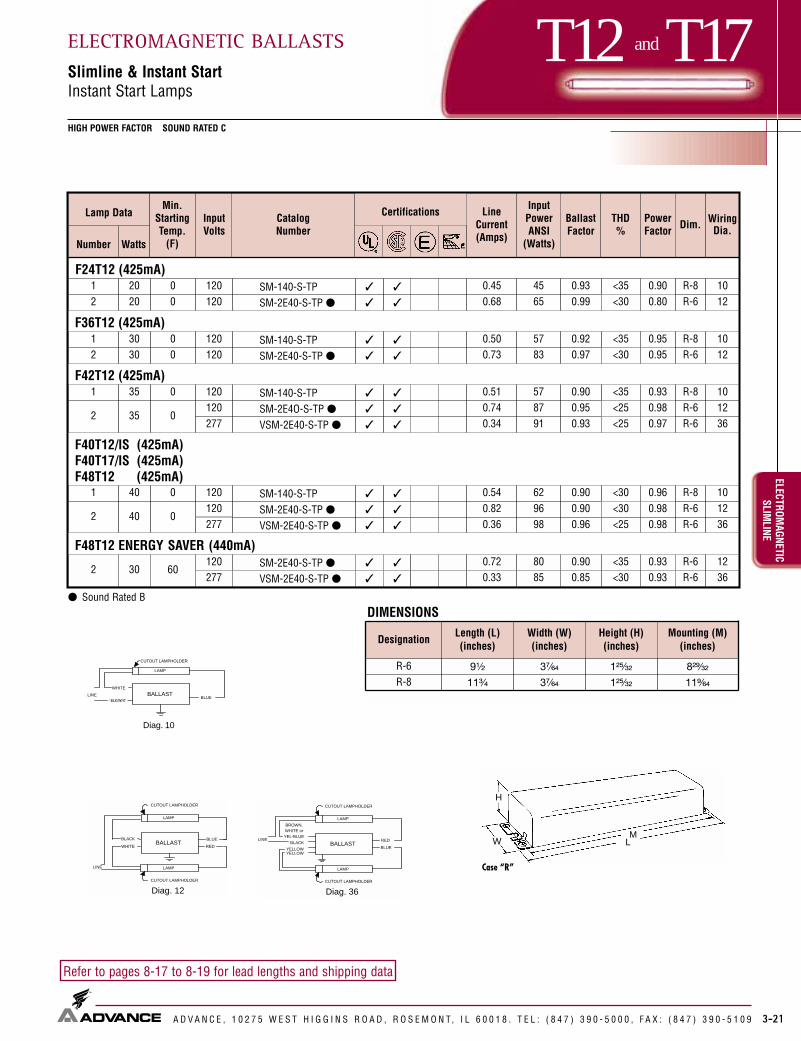
3-21
T12 and T17HIGH POWER FACTOR SOUND RATED C
ELECTROMAGNETIC
SLIMLINE
ELECTROMAGNETIC BALLASTSSlimline & Instant StartInstant Start Lamps
A D V A N C E , 1 0 2 7 5 W E S T H I G G I N S R O A D , R O S E M O N T, I L 6 0 0 1 8 . T E L : ( 8 4 7 ) 3 9 0 - 5 0 0 0 , F A X : ( 8 4 7 ) 3 9 0 - 5 1 0 9
Refer to pages 8-17 to 8-19 for lead lengths and shipping data
Case “R”
MLW
H
BALLASTBLK/WHT
Diag. 10
LINEBLUE
LAMP
WHITE
CUTOUT LAMPHOLDER
BALLASTBLACK
Diag. 12
LINE
BLUE
LAMP
WHITE
LAMP
RED
CUTOUT LAMPHOLDER
CUTOUT LAMPHOLDER
BALLAST
Diag. 36
LINE
LAMP
LAMP
CUTOUT LAMPHOLDER
CUTOUT LAMPHOLDER
RED
BLUEYELLOWYELLOW
BLACK
BROWN,WHITE orYEL-BLUE
BLK/WHT
1 20 1200 SM-140-S-TP ✓ ✓ 0.45 45 0.93 R-82 20 1200 SM-2E40-S-TP ● ✓ ✓ 0.68 65 0.99 R-6
1 30 1200 SM-140-S-TP ✓ ✓ 0.50 57 0.92 R-80 SM-2E40-S-TP ● ✓ ✓ 0.73 83 0.97 R-6
1 35 120
277
0 SM-140-S-TP ✓ ✓ 0.51 57 0.90 R-8
0SM-2E4O-S-TP ● ✓ ✓ 0.74 87 0.95 R-6
VSM-2E40-S-TP ● ✓ ✓ 0.34 91 0.93 R-6
1 40 1200 SM-140-S-TP ✓ ✓ 0.54 62 0.90 R-8
0SM-2E40-S-TP ● ✓ ✓ 0.82 96 0.90 R-6
277 VSM-2E40-S-TP ● ✓ ✓ 0.36 98 0.96 R-6
F24T12 (425mA)<35
F36T12 (425mA)
2 30 120<35
2 35120
<35F42T12 (425mA)
F40T12/IS (425mA)F40T17/IS (425mA)F48T12 (425mA)
2 40120
<30
● Sound Rated B
<30
<30
<25<25
<25<30
F48T12 ENERGY SAVER (440mA)
2 30120 <35
<30
0.90
0.95
0.93
0.96
0.80
0.95
0.980.97
0.980.98
0.930.93
60SM-2E40-S-TP ● ✓ ✓ 0.72 80 0.90 R-6
VSM-2E40-S-TP ● ✓ ✓ 0.33 85 0.85 R-6
1012
1012
101236
101236
1236277
DesignationLength (L)(inches)
Width (W)(inches)
Height (H)(inches)
Mounting (M)(inches)
R-6 9¹�₂ 3⁷�₆₄ 1²⁵�₃₂ 8²⁹�₃₂
R-8 11³�₄ 3⁷�₆₄ 1²⁵�₃₂ 11⁹�₆₄
DIMENSIONS
Min.StartingTemp.
(F)
InputVolts
CatalogNumber
Certifications LineCurrent(Amps)
InputPowerANSI
(Watts)
BallastFactor
THD%
PowerFactor Dim. Wiring
Dia.WattsNumber
Lamp Data

3-22
T12 SLIMLINE
HIGH POWER FACTOR SOUND RATED C
ELEC
TROM
AGNE
TIC
SLIM
LINE
ELECTROMAGNETIC BALLASTSSlimlineInstant Start Lamps
A D V A N C E , 1 0 2 7 5 W E S T H I G G I N S R O A D , R O S E M O N T, I L 6 0 0 1 8 . T E L : ( 8 4 7 ) 3 9 0 - 5 0 0 0 , F A X : ( 8 4 7 ) 3 9 0 - 5 1 0 9
Refer to pages 8-17 to 8-19 for lead lengths and shipping data
1200
RSM-175-S-TP ✓ ✓ 0.74 73 0.93277 VSM-175-S-TP ✓ ✓ 0.31 72 0.93
0
R-2E75-S-TP Mark III R ✓ ✓ 1.03 111 0.94
SM-2E57-S-TP ✓ ✓ 1.14 122 0.90
V-2E75-S-TP Mark III R ✓ ✓ 0.47 118 0.93
1200
RSM-175-S-TP ✓ ✓ 0.73 80 0.95277 VSM-175-S-TP ✓ ✓ 0.32 81 0.94
R-2E75-S-TP Mark III R ✓ ✓ 1.18 132 0.94
YSM-2E75-S-TP ✓ 0.58 130 0.92
V-2E75-S-TP Mark III R ✓ ✓ 0.51 132 0.94
50 R-2E75-S-TP Mark III R ✓ ✓ 1.28 147 0.950 RC-2E75-S-TP R ✓ ✓ 1.28 147 0.950
YSM-2E75-S-TP ✓ 0.63 144 0.92
V-2E75-S-TP Mark III R ✓ ✓ 0.57 151 0.94
1
2
50
50
120
F72T12 (425mA)
<50
<30
R-6
R-8
F60T12 (425mA)
1 57
2
F84T12 (425mA)
2
57
120
240
<35
<30
R-6
65
120
240
<30
0 VC-2E75-S-TP R ✓ ✓ 0.57 151 0.94
F64T12 (425mA)
R-6<50120
0RSM-175-S-TP ✓ ✓ 0.72 74 0.94
52277 VSM-175-S-TP ✓ ✓ 0.31 74 0.93
1
<30
2 52
120
0
R-2E75-S-TP Mark III R ✓ ✓ 1.07 117 0.95
SM-2E57-S-TP ✓ ✓ 1.19 131 0.93
277 V-2E75-S-TP Mark III R ✓ ✓ 0.47 120 0.93
<25
SM-2E57-S-TP ✓ ✓ 1.25 140 0.95
YSM-2E75-S-TP ✓ 0.50 109 0.93
<50
<30<25
<25
<50
YSM-2E75-S-TP ✓ 0.51 114 0.90<30<25
<25
<35
<20
<25
<25<25<30
<30
<25347 G-2E75-S-TP Mark III R ✓ 0.37 116 0.91
<25347 G-2E75-S-TP Mark III R ✓ 0.39 122 0.91
277240
<25347 G-2E75-S-TP Mark III R ✓ 0.42 133 0.93
240
36
12
36
10
12
10
12
10
12
36
36
<25
0.90
0.90
0.91
0.93
0.96
0.90
0.91
0.93
0.90
0.910.91
0.90
0.90
0.920.93
0.92
0.91
0.93
0.93
0.960.960.95
0.96
0.90
0.90
0.91
0.9434750 G-2E75-S-TP Mark III R ✓ 0.45 147 0.92
277
277
0
Min.StartingTemp.
(F)
InputVolts
CatalogNumber
Certifications LineCurrent(Amps)
InputPowerANSI
(Watts)
BallastFactor
THD%
PowerFactor Dim. Wiring
Dia.WattsNumber
Lamp Data
R For Replacement Use Only
R-8
R-8
R-8
XSM-2E75-S-TP ✓ 0.60 121 0.95 <25220 0.91
See page 3-23 for Dimensions and Wiring
XSM-2E75-S-TP ✓ 0.63 123 0.96 <20220 0.89
XSM-2E75-S-TP ✓ 0.69 137 0.94 <20220 0.90
XSM-2E75-S-TP ✓ 0.74 156 0.96 <25220 0.96
50

3-23
T12 SLIMLINE
HIGH POWER FACTOR SOUND RATED C
ELECTROMAGNETIC
SLIMLINE
ELECTROMAGNETIC BALLASTSSlimlineInstant Start Lamps
A D V A N C E , 1 0 2 7 5 W E S T H I G G I N S R O A D , R O S E M O N T, I L 6 0 0 1 8 . T E L : ( 8 4 7 ) 3 9 0 - 5 0 0 0 , F A X : ( 8 4 7 ) 3 9 0 - 5 1 0 9
Refer to pages 8-17 to 8-19 for lead lengths and shipping data
BALLASTBLK/WHT
Diag. 10
LINEBLUE
LAMP
WHITE
CUTOUT LAMPHOLDER
Min.StartingTemp.
(F)
InputVolts
CatalogNumber
Certifications LineCurrent(Amps)
InputPowerANSI
(Watts)
BallastFactor
THD%
PowerFactor Dim. Wiring
Dia.WattsNumber
Lamp Data
120 RSM-175-S-TP ✓ ✓ 0.82 0.94277 VSM-175-S-TP ✓ ✓ 0.35 0.94
R-2E60-S-TP E-Pak R ✓ ✓ ✓ ✓ 1.24 144 0.86
V-2E75-S-TP Mark III R ✓ ✓ ✓ ✓ 0.60 158 0.94VC-2E75-S-TP R ✓ ✓ ✓ ✓ 0.60 158 0.94
120 RSM-175-S-TP ✓ ✓ 0.68277 VSM-175-S-TP ✓ ✓ 0.30
120R-2E60-S-TP E-Pak R ✓ ✓ ✓ ✓ 1.03
240 YSM-2E75-S-TP ✓ 0.60 R-8
F96T12 (425mA)
1
2
F96T12 Energy Saver (440mA)
1
2
75
75
60
60
120
277
O
60
92
74
112
0.88
<25
<35
R-6
R-6
<30
0.88 <35
347 G-2E75-S-TP Mark III R ✓ ✓ 0.49 158 0.94 <25
347 G-2E75-S-TP Mark III R ✓ ✓ 0.40 126 0.88 <30
76
131
94
0.90
126 0.88R-2E75-S-TP Mark III R ✓ ✓ ✓ ✓ 1.10
R-2E75-S-TP Mark III R ✓ ✓ ✓ ✓ 1.35 158 0.94
<25V-2E60-S-TP E-Pak R ✓ ✓ ✓ ✓ 0.54 144 0.86 <30
R-850
YSM-2E75-S-TP ✓ 0.67 155 0.92
126 0.88V-2E75-S-TP Mark III R ✓ ✓ ✓ ✓ 0.47 <25112 0.88
277V-2E60-S-TP E-Pak R ✓ ✓ ✓ ✓ 0.44 <35
0.88 <35
<35
<35
<25
240
RC-2E75-S-TP R ✓ ✓ ✓ ✓ 1.35 158 0.940
<30
<30<30
<25
0.93
0.91
0.98
0.91
0.93
0.91
0.950.96
0.970.92
0.91
0.91
0.95
0.97
0.96
0.980.98
0.95
12
12
36
10
10
36
Case “R”
MLW
H
BALLASTBLACK
Diag. 12
LINE
BLUE
LAMP
WHITE
LAMP
RED
CUTOUT LAMPHOLDER
CUTOUT LAMPHOLDER
BALLAST
Diag. 36
LINE
LAMP
LAMP
CUTOUT LAMPHOLDER
CUTOUT LAMPHOLDER
RED
BLUEYELLOWYELLOW
BLACK
BROWN,WHITE orYEL-BLUE
50
0
DesignationLength (L)(inches)
Width (W)(inches)
Height (H)(inches)
Mounting (M)(inches)
R-6 9¹�₂ 3⁷�₆₄ 1²⁵�₃₂ 8²⁹�₃₂
R-8 11³�₄ 3⁷�₆₄ 1²⁵�₃₂ 11⁹�₆₄
DIMENSIONS
60
R For Replacement Use Only
XSM-2E75-S-TP ✓ 0.71 139 0.91 <30220 0.89
XSM-2E75-S-TP ✓ 0.81 169 0.93 <25220 0.95

3-24
T5 CLASS B INSULATION NORMAL POWER FACTOR SOUND RATED A
ELEC
TROM
AGNE
TIC
PREH
EAT
ELECTROMAGNETIC BALLASTSPreheat LampsPreheat Ballasts (Starter Required)
A D V A N C E , 1 0 2 7 5 W E S T H I G G I N S R O A D , R O S E M O N T, I L 6 0 0 1 8 . T E L : ( 8 4 7 ) 3 9 0 - 5 0 0 0 , F A X : ( 8 4 7 ) 3 9 0 - 5 1 0 9
Refer to pages 8-17 to 8-19 for lead lengths and shipping data
BALLAST
LAMP
BLACK BLACK
S
Diag. 1
LINE BALLAST
LAMP
BLACK
S
Diag. 2
LINEBLUEWHITE
Case “C”
ML
W
H
³⁄₁₆" Slots
ML
Case “R”
MLW
H
Case X-1, X-2
ML
W
H
³⁄₁₆" Holes1/8” Holes
✖ Available with Class P Thermal Protection— Add Suffix -TP toCatalog Number.
◆ Open Core & Coil Ballasts are available without mounting feet—Add Suffix -A to Calalog Number. Units without mounting feet areUL Component Recognized.
★ Core & Coil with Cover, painted white❏ For Emergency/Exit Fixture applications, add suffix “R” to Catalog
Number. Ballasts with this suffix are UL component recognized.✩ Ballast Includes Built-in Starter✝ Class A Insulation
BLK/WHT
LAMP
RED/WHT
BLU/WHT
BLUE
BLK/WHTLIN
E BALLAST
DIAG. 119 BALLAST
LAMP1 LAMP2
BLU/WHT
BLU/WHT
RED/WHT
RED/WHT
BLUE BLUE
BLACK
LINE
Diag. 136 Case X-1, X-2
LPL-5-9 ◆✖❏ ✓ ✓ 0.19 1.01
LC-4-9-C ★✖ ✓ ✓ 0.20 1.07X-1C-2
LPL-5-9 ◆✖❏ ✓ ✓ 0.17 1.02
LC-4-9-C ★✖ ✓ ✓ 0.19 1.07X-1C-2
LPL-5-9 ◆✖❏ ✓ ✓ 0.14 1.00
LPL-7-9 ✓ ✓ 0.17 0.95
LC-4-9-C ★✖ ✓ ✓ 0.17 1.08
X-1X-2C-2
F4T5
1
F6T5
1
F8T5
1
4
6
8
120
120
120
50
50
50
9
9
9
<10
<10
<10
9
F13T5
1 13 12050L-1Q13-TP-W ✓ ✓ 0.33 18 0.95 <10
<10
10 <10
1111
<10<10
LS-113-TP ✝ ✓ ✓ 0.28 17 0.89 <10R-4LS
LSX-213-TP ✩ ✝ ✓ ✓ 0.29 26 0.88 <25LSX-113-TP ✩ ✝ ✓ ✓ 0.14 13 0.88 <15 LS
2 13 12050 LS
LSX-113-TP ✩ ✝ ✓ ✓ 0.14 10 0.99 <10 LS2 8 12050 LSX-213-TP ✩ ✝ ✓ ✓ 0.29 19 0.99 <15 LS
(1) F8T5 & (1) F13T52 LSX-213-TP ✩ ✝ ✓ ✓ 0.29 23 0.93 <20
0.39
0.44
0.54
0.45
0.38
0.44
0.540.54
0.51
0.750.77
0.600.55
0.668 & 13 12050 LS
116116
116116
116116116
22
119136
119136
136
50 12081
50 120131
DesignationLength (L)(inches)
Width (W) (inches) Height (H)(inches)
Mounting (M)(inches)
C-2 3¹�₁₆ 1³�₈ 1¹³�₁₆ 2³⁄₄
X-1 2³�₈ 1¹�₈ 1³�₈ 2
X-2 2³�₈ ¹⁵�₁₆ 1³�₈ 2
Standard With TP
—
1¹⁹�₃₂
1³�₈
LS 6⁷�₁₆ — ¹⁵�₁₆ 2³�₈1¹³�₁₆
R-4 6¹�₂ — 1³�₈ 6+1¹⁵�₁₆
DIMENSIONS
Diag.116
Min.StartingTemp.
(F)
InputVolts
CatalogNumber
Certifications LineCurrent(Amps)
InputPowerANSI
(Watts)
BallastFactor
THD%
PowerFactor Dim. Wiring
Dia.WattsNumber
Lamp Data
✩

3-25
T8CLASS B INSULATION NORMAL POWER FACTOR SOUND RATED A
ELECTROMAGNETIC
PREHEATELECTROMAGNETIC BALLASTSPreheat LampsPreheat Ballasts (Starter Required)
A D V A N C E , 1 0 2 7 5 W E S T H I G G I N S R O A D , R O S E M O N T, I L 6 0 0 1 8 . T E L : ( 8 4 7 ) 3 9 0 - 5 0 0 0 , F A X : ( 8 4 7 ) 3 9 0 - 5 1 0 9
Refer to pages 8-17 to 8-19 for lead lengths and shipping data Case “C”
ML
W
H
³⁄₁₆" Slots
ML
Case X-3, X-5, X-6, X-7
ML
W
H
³⁄₁₆" Slots
BALLAST
LAMP
BLACK BLACK
S
Diag. 1
LINE
BALLAST
LAMP
BLACK
S
Diag. 2
LINEBLUEWHITE
BALLAST
LAMP
BLACK
S
Diag. 3
LINE
BLUE
LAMP
S
BLUE
BALLAST
LAMP
Diag. 4
BLACK
WHITE
RED/WHITE
BLUE
BLUE/WHITE
LINE
✖ Available with Class P Thermal Protection— Add Suffix -TP to Catalog Number.
◆ Open Core & Coil Ballasts are available without mounting feet—Add Suffix -A to Catalog Number. Units without mounting feet are UL Component Recognized.
★ Core & Coil with Cover, painted white❏ For Emergency/Exit Fixture applications, add suffix “R” to Catalog
Number. Ballasts with this suffix are UL component recognized.✩ Ballast Includes Built-in Starter.✝ Class A Insulation ● Sound Rated B
BLK/WHT
BLK/WHT
DesignationLength (L)(inches)
Width (W) (inches) Height (H)(inches)
Mounting (M)(inches)
C-2 3¹�₁₆ 1³�₈ 1¹³�₁₆ 2³�₄
R-4 6¹�₂ — 1³�₈ 6+
X-3 3¹�₁₆ 1¹�₄ 1¹³�₁₆ 2³�₄
Standard With TP
1¹⁹�₃₂
1¹⁵�₁₆
1⁷�₁₆
+ Mounting dimensions refer to slots only
—R-1 4¹�₄ 2 1⁷�₁₆ 3⁹�₁₆
LO-13-22 ◆✖❏ ✓ ✓ 0.32 18 0.90
LC-14-20-C ★✖ ✓ ✓ 0.37 20 0.97X-3C-2
LO-13-22 ◆✖❏ ✓ ✓ 18 0.96
LC-14-20-C ★✖ ✓ ✓ 20 1.08
2 15 12050 L-220F ✝● ✓ ✓ 0.57 34 0.93 <10 R-4
LO-13-22 ◆✖❏ ✓ ✓ 0.29 17 0.80
LC-14-20-C ★✖ ✓ ✓ 0.33 20 0.92X-3C-2
LO-13-22 ◆✖❏ ✓ ✓ 0.28 17 0.90
LC-14-20-C ★✖ ✓ ✓ 0.33 20 0.92X-3C-2
L-140F-TP ✝ ✓ ✓ 0.96 R-4
LX-140F-TP ✩✝ ✓ ✓ 1.00 R-4
F13T8
1 14 12050
1 15 120500.29 <10
F18T8
1 18 12050
F19T8
1 19 12050
<20
<15
<15
F30T8
1 30 120500.67 40 <15
0.34
0.64 40
<10
<10
<10
<15
<10
L-120F ✝● ✓ ✓ 0.28 17 0.88 <10
X-3C-2R-1
1 13 12050 LO-13-22 ◆✖❏ ✓ ✓ 0.34 17 0.91 <10
0.50
0.52
0.47
0.49
0.51
0.50
0.45
0.49
0.51
0.51
0.52
0.51
0.42
F15T8
X-3
116116
3
116116
116116
42
116116116
116
F14T8
DIMENSIONS
Diag.116 Case “R”
MLW
H
Min.StartingTemp.
(F)
InputVolts
CatalogNumber
Certifications LineCurrent(Amps)
InputPowerANSI
(Watts)
BallastFactor
THD%
PowerFactor Dim. Wiring
Dia.WattsNumber
Lamp Data
✩

3-26
T12CLASS B INSULATION NORMAL POWER FACTOR SOUND RATED A
ELEC
TROM
AGNE
TIC
PREH
EAT
ELECTROMAGNETIC BALLASTSPreheat LampsPreheat Ballasts (Starter Required)
A D V A N C E , 1 0 2 7 5 W E S T H I G G I N S R O A D , R O S E M O N T, I L 6 0 0 1 8 . T E L : ( 8 4 7 ) 3 9 0 - 5 0 0 0 , F A X : ( 8 4 7 ) 3 9 0 - 5 1 0 9
Refer to pages 8-17 to 8-19 for lead lengths and shipping data
DesignationLength (L)(inches)
Width (W) (inches) Height (H)(inches)
Mounting (M)(inches)
C-2 3¹�₁₆ 1 ³⁄₈ 1¹³�₁₆ 2³�₄
R-1 4¹�₄ 2 1⁷�₁₆ 3⁹�₁₆
R-4 6¹�₂ — 1³�₈ 6+
Standard
1¹⁹�₃₂
—1¹⁵�₁₆
With TP
X-3 3¹�₁₆ 1¹�₄ 1⁷�₁₆ 1¹³�₁₆ 2³�₄
+ Mounting dimensions refer to slots only
Case “R”
MLW
H
BALLAST
LAMP
BLACK BLACK
S
Diag. 1
LINE
BALLAST
LAMP
BLACK
S
Diag. 2
LINEBLUEWHITE
BALLAST
LAMP
Diag. 4
BLACK
WHITE
RED/WHITE
BLUE
BLUE/WHITE
LINE
BALLAST
LAMP
BLACK
S
Diag. 3
LINE
BLUE
LAMP
S
BLUE
BLK/WHT
Diag. 116
BLK/WHT
✖ Available with Class P Thermal Protection— Add Suffix -TP to Catalog Number.
◆ Open Core & Coil Ballasts are available without mounting feet—Add Suffix -A to Calalog Number. Units without mounting feet areUL Component Recognized.
★ Core & Coil with Cover, painted white❏ For Emergency/Exit Fixture applications, add suffix “R” to Catalog
Number. Ballasts with this suffix are UL component recognized.✩ Ballast Includes Built-in Starter.✝ Class A Insulation ● Sound Rated B
LO-13-22 ✖◆❏ ✓ ✓ 0.34 18 0.92 <10
LC-14-20-C ✖★ ✓ ✓ 0.39 21 1.01X-3C-2
LO-13-22 ✖◆❏ ✓ ✓ 18 0.97
LC-14-20-C ✖★ ✓ ✓ 1.10
L-120F ✝● ✓ ✓ 0.30 0.78
X-3C-2R-1
2 15 12050 L-220F ✝● ✓ ✓ 0.61 36 0.93 <10 R-4
LO-13-22 ✖◆❏ ✓ ✓ 0.28 18 0.77
LC-14-20-C ✖★ ✓ ✓ 0.33 0.93
L-120F ✝● ✓ ✓ 0.27 0.78
X-3C-2R-1
2 20 12050 L-220F ✝● ✓ ✓ 0.55 35 0.75 <10 R-4
L-140F-TP ✝ ✓ ✓ 0.95 R-4
LX-140F-TP ✝✩ ✓ ✓ 0.95 R-4
F14T12
1 14 12050
F15T12
1 15 12050 210.32
1 20 12050 21
F30T12
1 30 120500.73 41
<10
<10
<10
F40T12
1 40 120500.65 41 <15L-140F-TP ✝ ✓ ✓ 0.79 R-4
LX-140F-TP ✝✩ ✓ ✓ 0.83 R-4
1 25 12050 LC-25 ★✖ ✓ ✓ 0.36 24 0.90 <10 C-2
116116
1161161163
1161161163
24
24
116F25T12
<10
0.3818
19
0.73 40
0.63 40
<10<15
<10<10
<10
<10
0.44
0.49
0.53
0.47
0.54
0.47
0.53
0.56
0.45
0.500.46
0.590.53
0.46
0.53
DIMENSIONS
F20T12
Min.StartingTemp.
(F)
InputVolts
CatalogNumber
Certifications LineCurrent(Amps)
InputPowerANSI
(Watts)
BallastFactor
THD%
PowerFactor Dim. Wiring
Dia.WattsNumber
Lamp Data
✩
Case X-3, X-5, X-6, X-7
ML
W
H
³⁄₁₆" SlotsCase “C”
ML
W
H
³⁄₁₆" Slots
ML

3-27
T5 and T8NORMAL POWER FACTOR SOUND RATED A
ELECTROMAGNETIC
PREHEATELECTROMAGNETIC BALLASTSPreheat LampsTrigger Start Ballasts
A D V A N C E , 1 0 2 7 5 W E S T H I G G I N S R O A D , R O S E M O N T, I L 6 0 0 1 8 . T E L : ( 8 4 7 ) 3 9 0 - 5 0 0 0 , F A X : ( 8 4 7 ) 3 9 0 - 5 1 0 9
Refer to pages 8-17 to 8-19 for lead lengths and shipping data
F4T5 4WF6T5 6W F8T5 8W
BALLASTBLACK
Diag. 16
LINE
LAMP
WHITERED
REDBLUE
WHITE
CIRCUIT INTERRUPTINGLAMPHOLDER
BLUEBLUE
WHITEBLK/WHTLINE
BALLAST
LAMP
Diag. 20
REDRED
BALLAST
LAMP
LAMP
LAMP
Diag. 29
BLUEBLUE
YEL-BLUEYEL-BLUE
REDRED
YELLOWYELLOW
BLACKWHITELINE
Case “R”
MLW
H
❖ Requires Circuit-Interrupting Lamp Holders▲ High Power Factor● Sound Rated B
BLK/WHT
120 LQ-106F-TP ✓ 0.34 0.86 <25277 VLQ-106F-TP ✓ 0.16 0.96 <30
RLQ-120-TP ❖ ✓ ✓ 0.56 28 1.01 <10 R-4
HM-1P20-TP ▲ ✓ ✓ 0.24 27 0.90 <15T-2
277 VHM-1P20-TP ▲ ✓ ✓ 0.10 27 0.99 <1550 RL-2SP20-TP ✓ ✓ 0.51 36 0.78 <1520 HM-2SP20-TP ▲ ✓ ✓ 0.47 51 0.99 <20
T-1
T-2277 VM-2SP20-TP ▲ ✓ 0.21 55 0.94 <20
3 15 12050 RL-3SP20-TP 0.80 64 0.72 <30 R-5
F15T8
1 8 5014
R-4
1 15120
50
2 15120
14
F30T82 30 1200 RC-2SP830-TP ▲● ✓ ✓ 0.70 82 0.91 <25 R-5
F13T81 13 12020 RLQ-120-TP ❖ ✓ ✓ 0.54 23 1.00 <10 R-42 13 12030 RL-2SP20-TP ✓ ✓ 0.58 36 1.00 <10
0.340.36
0.420.940.970.590.900.950.67
0.98
0.350.52 T-1
0
0
DesignationLength (L)(inches)
Width (W)(inches)
Height (H)(inches)
Mounting (M)(inches)
R-4 6¹�₂ 1¹⁵�₁₆ 1³�₈ 6+
R-5 9¹�₂ 2³�₈ 1¹¹�₁₆ 8²⁹�₃₂
T-1 6¹�₂ 2³�₈ 1¹�₂ 6+
T-2 9¹�₂ 2³�₈ 1¹�₂ 8²⁹�₃₂
+ Mounting dimensions refer to slots only
DIMENSIONS
2 8 LQ-206F-TP ✓ 0.47 21 0.74 <30 R-4
16
20
21
21
29
20
21
1621
210.3750 120
Min.StartingTemp.
(F)
InputVolts
CatalogNumber
Certifications LineCurrent(Amps)
InputPowerANSI
(Watts)
BallastFactor
THD%
PowerFactor Dim. Wiring
Dia.WattsNumber
Lamp Data

3-28
T12HIGH POWER FACTOR SOUND RATED A
ELEC
TROM
AGNE
TIC
PREH
EAT
ELECTROMAGNETIC BALLASTSPreheat LampsTrigger Start Ballasts
A D V A N C E , 1 0 2 7 5 W E S T H I G G I N S R O A D , R O S E M O N T, I L 6 0 0 1 8 . T E L : ( 8 4 7 ) 3 9 0 - 5 0 0 0 , F A X : ( 8 4 7 ) 3 9 0 - 5 1 0 9
Refer to pages 8-17 to 8-19 for lead lengths and shipping data
50 RLQ-120-TP ❖❉ ✓ ✓ 0.58 0.92 <10 R-4
HM-1P20-TP ✓ ✓ 0.21 0.82 <10T-2
277 VHM-1P20-TP ✓ ✓ 0.09 25 0.84 <10120 HM-2SP20-TP ✓ ✓ 0.43 46 0.85 <10277 VM-2SP20-TP ✓ 0.19 47 0.88 <15
120RLQ-120-TP ❖❉ ✓ ✓ 0.58 0.99 <10 R-4
HM-1P20-TP ✓ ✓ 0.23 0.89 <15277 VHM-1P20-TP ✓ ✓ 0.10 0.94 <10
12050 RL-2SP20-TP ❉ ✓ ✓ 0.57 41 0.83 <10
HM-2SP20-TP ✓ ✓ 0.44 47 0.92 <15277 VM-2SP20-TP ✓ 0.18 46 0.98 <15
F14T12
1 14120
28
2 14 0 T-2
F15T12
1 152950
T-2
2 15 10T-1
T-2
3 15 12050 RL-3SP20-TP ❉ ✓ ✓ 0.89 63 0.94 <10 R-5
F20T12
1 202850
T-2120
RLQ-120-TP ❖❉ ✓ ✓ 0.55 0.83 <10 R-4
HM-1P20-TP ✓ ✓ 0.24 0.83 <20277 VHM-1P20-TP ✓ ✓ 0.11 0.81 <15
2 20 10120
50 RL-2SP20-TP ❉ ✓ ✓ 0.49 36 0.61 <15
T-2
T-1
HM-2SP20-TP ✓ ✓ 0.48 53 0.90 <20277 VM-2SP20-TP ✓ 0.21 54 0.86 <20
3 20 12050 RL-3SP20-TP ❉ ✓ ✓ 0.80 64 0.71 <15
0.400.950.990.900.90
0.420.980.970.600.900.920.59
0.420.990.980.610.920.930.67 R-5
16
20
16
21
20
21
21
29
20
16
21
21
29
24
2727
3029
0
0
0
0
0
DesignationLength (L)(inches)
Width (W)(inches)
Height (H)(inches)
Mounting (M)(inches)
R-4 6¹�₂ 1¹⁵�₁₆ 1³�₈ 6+
R-5 9¹�₂ 2³�₈ 1¹¹�₁₆ 8²⁹�₃₂
T-1 6¹�₂ 2³�₈ 1¹�₂ 6+
T-2 9¹�₂ 2³�₈ 1¹�₂ 8²⁹�₃₂
+ Mounting dimensions refer to slots only
DIMENSIONS
Case “R”
MLW
H
BALLASTBLACK
Diag. 16
LINE
LAMP
WHITERED
REDBLUE
WHITE
CIRCUIT INTERRUPTINGLAMPHOLDER
BALLAST
LAMP
LAMP
LAMP
Diag. 29
BLUEBLUE
YEL-BLUEYEL-BLUE
REDRED
YELLOWYELLOW
BLACKWHITELINE
BLUEBLUE
WHITEBLK/WHTLINE
BALLAST
LAMP
Diag. 20
REDRED
BLK/WHT
❖ Requires Circuit-Interrupting Lamp Holders❉ Normal Power Factor
Min.StartingTemp.
(F)
InputVolts
CatalogNumber
Certifications LineCurrent(Amps)
InputPowerANSI
(Watts)
BallastFactor
THD%
PowerFactor Dim. Wiring
Dia.WattsNumber
Lamp Data

3-30
T9NORMAL POWER FACTOR SOUND RATED A
ELEC
TROM
AGNE
TIC
CIRC
LINE
ELECTROMAGNETIC BALLASTSCircline LampsRapid Start Ballasts
A D V A N C E , 1 0 2 7 5 W E S T H I G G I N S R O A D , R O S E M O N T, I L 6 0 0 1 8 . T E L : ( 8 4 7 ) 3 9 0 - 5 0 0 0 , F A X : ( 8 4 7 ) 3 9 0 - 5 1 0 9
Refer to pages 8-17 to 8-19 for lead lengths and shipping data
Case “R”
MLW
H
BALLASTBLACK
BLUE
RED
RED
WHITE
Diag. 31
LINE
FOR POSITIVESTARTING, SPACE3 METAL CLIPS12O ° APART ASILLUSTRATED
BALLASTBLACK
BLUE
REDRED
WHITE
Diag. 32
LINE
FOR POSITIVESTARTING, SPACE3 METAL CLIPS12O ° APART ASILLUSTRATED
WHITE
Diag. 105
Note: All Ballasts supplied with Circline sockets in white can except RL-140-TP
BLK/WHT
BLK/WHT
▲ High Power Factor
RLQS-122-TP-W ✓ ✓ 0.76 <10 R-4
RL-140-TP ✓ ✓ 0.68 <15 R-4
RLCS-140-TP-W ✓ ✓ 0.63 <10 R-4
RS-22-32-TP-W ✓ ✓ 0.70 <15T-1
RMS-22-32-TP-W ▲ ✓ ✓ 0.36 0.61 <15
RS-32-40-TP-W ✓ ✓ 0.60 <20T-1
RMS-32-40-TP-W ▲ ✓ ✓ <15
FC6T9 (20W Circline)1 20 12050 0.56 24
1 32 120500.59 32
FC12T9 (32W Circline)
2 22 &32 12050
0.40 46
(1)FC12T9 & (1)FC16T9 ((1)32W & (1)40W Circline)
2 32 &40 12050
0.76 56
(1)FC8T9 & (1)FC12T9 ((1)22W & (1)32W Circline)
FC8T9 (22W Circline)1 22 12050 0.53 25RLQS-122-TP-W ✓ ✓ 0.75 <10 R-4
1 40 120500.46 29RL-140-TP ✓ ✓ 0.55 <15 R-4
RLCS-140-TP-W ✓ ✓ 0.50 <15
0.36
0.450.45
0.960.93
0.610.96
0.39
0.530.53 R-4
32
3132
105
105
32
3132
FC16T9 (40W Circline)
0.57 31
40
0.52 60 0.70
0.44 28
DesignationLength (L)(inches)
Width (W)(inches)
Height (H)(inches)
Mounting (M)(inches)
R-4 6¹�₂ 1¹⁵�₁₆ 1³�₈ 6+
T-1 6¹�₂ 2³�₈ 1¹�₂ 6+
DIMENSIONS
+ Mounting dimensions refer to slots only
Min.StartingTemp.
(F)
InputVolts
CatalogNumber
Certifications LineCurrent(Amps)
InputPowerANSI
(Watts)
BallastFactor
THD%
PowerFactor Dim. Wiring
Dia.WattsNumber
Lamp Data

3-31
T4CLASS B INSULATION NORMAL POWER FACTOR SOUND RATED A
ELECTROMAGNETIC
COMPACT
ELECTROMAGNETIC BALLASTS2-Pin Compact LampsPreheat Ballasts
A D V A N C E , 1 0 2 7 5 W E S T H I G G I N S R O A D , R O S E M O N T, I L 6 0 0 1 8 . T E L : ( 8 4 7 ) 3 9 0 - 5 0 0 0 , F A X : ( 8 4 7 ) 3 9 0 - 5 1 0 9
Refer to pages 8-17 to 8-19 for lead lengths and shipping data
CFT5W/G23 - 5W Twin Tube Lamp (PL-S5W, F5BX, CF5DS)1 5 0 LPL-5-9-TP ◆ ❏ ✓ ✓ 0.19 0.19 — 9 <10 X-1
CFT7W/G23 - 7W Twin Tube Lamp (PL-S7W, F7BX, CF7DS)
1 7 0LPL-5-9-TP ◆ ❏ ✓ ✓ 0.17 0.19 — 9 <10
LC-4-9-C-TP ★ ✓ ✓ 0.19 0.20 — <10X-1C-2
CFT9W/G23 - 9W Twin Tube Lamp (PL-S9W, F9BX, CF9DS)CFQ9W/G23 - 9W Quad Tube Lamp (F9DBX23T4, CF9DD)
1 9 25LPL-5-9-TP ◆ ❏ ✓ ✓ 0.14 0.19 — 10 <10
LC-4-9-C-TP ★ ✓ ✓ 0.16 0.20 — <10X-1C-2
1 13 32LC-13-TP ★ ✓ ✓ 0.27 0.37 — 16 <15
LO-13-22-TP ◆ ✓ ✓ 0.29 0.44 — 17 <15
VLO-13-TP ◆ ✓ ✓ 0.30 0.35 — 22 <10
C-2X-3X-5
2 13 32 VLO-2S13-TP ◆ ✓ 0.31 0.38 — 34 X-8
140
140140
140140
14014014046
10
11
1.06
0.96
0.89
0.931.001.000.95
1.06
1.00
BALLAST
LINE LAMPCAPOPTIONAL
BLACK
WHITE
BLUE
BALLAST
Diag. 46
LINECAPOPTIONAL
BLACK
WHITE
BLUE
Case “C”
ML
W
H
³⁄₁₆" Slots
ML
Case X-1, X-2
ML
W
H
³⁄₁₆" Holes
Case X-3, X-5, X-6, X-7
ML
W
H
³⁄₁₆" Slots
DIMENSIONS
Case “C” Case X-1 Case X-3, X-5, X-8
Above Units Available for Outdoor Fixtures labeled“Outdoor Use Only.” Eliminate TP from Catalog Number.◆ Open Core & Coil Ballasts are available without mounting feet—
Add Suffix -A to Calalog Number. Units without mounting feetare UL Component Recognized.
★ Core & Coil with Cover, painted white❏ For Emergency/Exit Fixture Applications, add Suffix “R” to
Catalog Number. Ballast with this Suffix are UL ComponentRecognized.
DesignationLength (L)(inches)
Width (W) (inches) Height (H)(inches)
Mounting (M)(inches)
C-2 3¹�₁₆ 1³�₈ 1¹³�₁₆ 2³�₄
X-1 2³�₈ 1¹�₈ 1³�₈ 2
X-3 3¹�₁₆ 1¹�₄ 1¹³�₁₆ 2³�₄
X-5 3¹�₄ 1¹�₂ 2 2¹³�₁₆
Standard With TP
1¹⁹�₃₂
1³�₈
1⁷�₁₆
1³�₄
X-8 4 1⁹�₁₆ 2¹⁄₄ 3¹�₂1¹³�₁₆
Diag.140
Min.StartingTemp.
(F)
InputVolts
CatalogNumber
Certifications Line Current (Amps) InputPowerANSI
(Watts)
BallastFactor
THD % Dim. Wiring
Dia.WattsNumber
Lamp Data
Operating Starting OpenCircuit
120
120
120
120
277277 <15
CFT13W/GX23 - 13W Twin Tube Lamp (PL-S13W, F13BX, CF13DS)CFQ13W/GX23 - 13W Quad Tube Lamp (PL-C13W/USA, F13DBX23T4, CF13DD)

3-32
T4 and T5 CLASS B INSULATION NORMAL POWER FACTOR SOUND RATED A
ELEC
TROM
AGNE
TIC
COM
PACT
ELECTROMAGNETIC BALLASTS2-Pin Compact & 4-Pin Long Twin Tube LampsPreheat Ballasts
A D V A N C E , 1 0 2 7 5 W E S T H I G G I N S R O A D , R O S E M O N T, I L 6 0 0 1 8 . T E L : ( 8 4 7 ) 3 9 0 - 5 0 0 0 , F A X : ( 8 4 7 ) 3 9 0 - 5 1 0 9
Refer to pages 8-17 to 8-19 for lead lengths and shipping data
BALLAST
LINE LAMPCAPOPTIONAL
BLACK
WHITE
BLUE
BALLAST
Diag. 44
LINE
S
CAPOPTIONAL
BLACK
WHITEBLUE
Diag. 107
BALLAST
BLACK
BLACK
LINE
WHITE
CAPOPTIONAL
Case “C”
ML
W
H
³⁄₁₆" Slots
ML
Case X-3, X-5, X-6, X-7
ML
W
H
³⁄₁₆" Slots
Case X-3, X-5, X-6, X-7, X-8
Above Units Available for Outdoor Fixtures labeled “OutdoorUse Only.” Eliminate TP from Catalog Number.◆ Open Core & Coil Ballasts are available without mounting feet—
Add Suffix -A to Calalog Number. Units without mounting feet are UL Component Recognized.
★ Core & Coil with Cover, painted whiteƒ For Outdoor Use Only
DIMENSIONS
FT18W/2G11 - 18W Long Twin Tube Lamp (PL-L18, F18BX, FT18DL) - Separate Starter Required
1 18 12050LC-25-TP ★ ✓ ✓ 0.39 0.59 — 22 1.05 <15
LO-13-22-TP ◆ ✓ ✓ 0.21 0.44 — 16 0.89 <20C-2X-3
CFQ20W/GX32d - 22W Quad Tube Lamp (PL-C 15mm/22W, FDL-22) 1 22 1200 LO-1Q22 ƒ ◆ ✓ ✓ 0.51 0.74 — 25 1.07 <20 X-7
CFQ26W/G24d - 26W Quad Tube Lamp (PL-C26W, F26DBXT4, CF26DD)1 26 27750 VLO-13-TP ◆ ✓ ✓ 0.27 0.35 — 29 0.80 <10 X-5
CFQ27W/GX32d - 28W Quad Tube Lamp (PL-C 15mm/28W, FDL-28)
1 28 120-20 LO-1Q28-TP ◆ ✓ ✓ 0.59 0.74 — 32 0.97 <10 X-8
LOS-1Q28 ƒ ◆ ✓ ✓ 0.61 0.74 — 32 0.97 <15
DesignationLength (L)(inches)
Width (W) (inches) Height (H)(inches)
Mounting (M)(inches)
C-2 3¹�₁₆ 1³�₈ 1¹³⁄₁₆ 2³�₄
X-3 3¹�₁₆ 1¹�₄ 1¹³�₁₆ 2³�₄
X-7 3¹�₁₆ 1³�₈ 1¹³�₁₆ 2³�₄
X-8 4 1⁹�₁₆ 2¹⁄₄ 3¹⁄₂
Standard With TP
1¹⁹�₃₂
1⁷�₁₆
—1¹³�₁₆
—X-6 3¹�₁₆ 1⁵�₈ 1¹³�₁₆ 2³�₄
1³�₄X-5 3¹�₄ 1¹�₂ 2 2¹³�₁₆
X-6
4444
107
140
140107
Diag. 140
Min.StartingTemp.
(F)
InputVolts
CatalogNumber
Certifications Line Current (Amps) InputPowerANSI
(Watts)
BallastFactor
THD % Dim. Wiring
Dia.WattsNumber
Lamp Data
Operating Starting OpenCircuit

3-33
T4HIGH POWER FACTOR SOUND RATED A
ELECTROMAGNETIC
COMPACT
ELECTROMAGNETIC BALLASTS2-Pin Compact LampsPreheat Ballasts
A D V A N C E , 1 0 2 7 5 W E S T H I G G I N S R O A D , R O S E M O N T, I L 6 0 0 1 8 . T E L : ( 8 4 7 ) 3 9 0 - 5 0 0 0 , F A X : ( 8 4 7 ) 3 9 0 - 5 1 0 9
Refer to pages 8-17 to 8-19 for lead lengths and shipping data
BALLASTLINEWHITE
WHITE
BLACK
BLUE
Case “R”
MLW
H
BALLAST
Diag. 51
LINE
WHITE
BLACK
BLUE
RED
BALLAST
Diag. 50
LINE
WHITE
BLACK
BLUE
WHITE
Diag. 47
✧ Ordering InformationAdd suffix -W to Catalog Number for white canwith leads exiting end of ballast. Add suffix -BLS to Catalog Number for black can with bottom leads and studs. See page 1-36.
❉ Normal Power Factor
DesignationLength (L)(inches)
Width (W)(inches)
Height (H)(inches)
Mounting (M)(inches)
R-1 4¹�₄ 2 1⁷�₁₆ 3⁹⁄₁₆
R-2 4³�₄ 2⁷⁄₃₂ 1⁵�₈ 4³⁄₈ +
T-1 6¹⁄₂ 2³⁄₈ 1¹⁄₂ 6+
CFT5W/G23 - 5W Twin Tube Lamp (PL-S5W, F5BX, CF5DS)
1 5120
0 L-1B9-TP ❉ ✓ ✓ 0.19 0.20 — 11 R-125 H-1B9-TP ✓ ✓ 0.10 0.20 0.13 11 R-1
2770VL-1B9-TP ❉ ✓ ✓ 0.17 0.18 — 15 R-2
VH-1B9-TP ✓ ✓ 0.05 0.18 0.17 11 R-2
CFT7W/G23 - 7W Twin Tube Lamp (PL-S7W, F7BX, CF7DS)
1 7120
0
L-1B9-TP ❉ ✓ ✓ 0.18 0.20 — 11 R-1
H-1B9-TP ✓ ✓ 0.10 0.20 0.13 11 R-1
277VL-1B9-TP ❉ ✓ ✓ 0.17 0.18 — 14 R-2
VH-1B9-TP ✓ ✓ 0.05 0.18 0.17 R-2
2 7120
0H-2B9-TP ✓ ✓ 0.23 0.21 — 22 T-1
277 VH-2B9-TP ✓ ✓ 0.07 0.16 0.10 16 <15 R-2
CFT9W/G23 - 9W Twin Tube Lamp (PL-S9W, F9BX, CF9DS) CFQ9W/G23 - 9W Quad Tube Lamp (F9DBX23T4, CF9DD)
1 912025
L-1B9-TP ❉ ✓ ✓ 0.16 0.20 — 11 0.86 R-1
H-1B9-TP ✓ ✓ 0.10 0.20 0.13 11 0.92 R-1
2770VL-1B9-TP ❉ ✓ ✓ 0.17 0.18 — 14 0.92 R-2
VH-1B9-TP ✓ ✓ 0.05 0.18 0.17 13 0.95
<10<20<15<35 R-2
2 912025 H-2B9-TP ✓ ✓ 0.25 0.21 — 28 1.00 <30 T-12770 VH-2B9-TP ✓ ✓ 0.07 0.16 0.10 17 0.82 <20 R-2
45474547
454745475150
454745475150
12
DIMENSIONS
+ Mounting dimensions refer to slots only
1.001.060.960.95
<10<20<12<35
1.001.000.950.931.000.85
<15<30
<10<20
<30<15
Min.StartingTemp.
(F)
InputVolts
CatalogNumber
Certifications Line Current (Amps) InputPowerANSI
(Watts)
BallastFactor
THD % Dim. Wiring
Dia.WattsNumber
Lamp Data
Operating Starting OpenCircuit
✧

3-34
T4HIGH POWER FACTOR SOUND RATED A
ELEC
TROM
AGNE
TIC
COM
PACT
ELECTROMAGNETIC BALLASTS2-Pin Compact LampsPreheat Ballasts
A D V A N C E , 1 0 2 7 5 W E S T H I G G I N S R O A D , R O S E M O N T, I L 6 0 0 1 8 . T E L : ( 8 4 7 ) 3 9 0 - 5 0 0 0 , F A X : ( 8 4 7 ) 3 9 0 - 5 1 0 9
Refer to pages 8-17 to 8-19 for lead lengths and shipping data
Case “R”
MLW
H
BALLAST
Diag. 51
LINE
WHITE
BLACK
BLUE
RED
BALLASTLINEWHITE
WHITE
BLACK
BLUE
BALLAST
Diag. 50
LINE
WHITE
BLACK
BLUE
WHITE
Diag. 47
✧ Ordering InformationAdd suffix -W to Catalog Number for white canwith leads exiting end of ballast.Add suffix -BLS to Catalog Number for black canwith bottom leads and studs. See page 1-36.
❉ Normal Power Factor✝✝ Cooler Operating for Insulated Ceiling
BLK/WHT
CFQ13W/G24d - 13W Quad Tube Lamp (PL-C13W, F13DBXT4)1 13 1200 L-1Q13-TP -W❉ ✓ ✓ 0.35 0.19 — 18 0.93 <10 R-4
CFT13W/GX23 - 13W Twin Tube Lamp (PL-S13W, F13BX, CF13DS)CFQ13W/GX23 - 13W Quad Tube Lamp (PL-C13W/USA, F13DBX23T4, CF13DD)
1 1312032
L-1B13-TP ❉ ✓ ✓ 0.26 0.30 — 16 0.93 R-1
H-1B13-TP ✓ ✓ 0.14 0.36 0.22 0.90<15<25 R-1
L-1BC13-TP ❉✝✝ ✓ ✓ 0.28 0.35 — 16 1.00R-2
2770VL-1B13-TP ❉ ✓ ✓ 0.26 0.28 — 24 0.98
VH-1B13-TP ✓ ✓ 0.10 0.30 0.26 0.99
<15<15<30 R-2
2 1312032 H-2B13-TP ✓ ✓ 0.30 0.44 — 35 1.02 <30 T-12770 VH-2B13-TP ✓ ✓ 0.10 0.35 0.21 27 0.92 <30 R-2
47
4547
45
475150
16
24
DesignationLength (L)(inches)
Width (W)(inches)
Height (H)(inches)
Mounting (M)(inches)
R-1 4¹�₄ 2 1⁷�₁₆ 3⁹⁄₁₆
R-2 4³⁄₄ 2⁷⁄₃₂ 1⁵�₈ 4³⁄₈ +
R-4 6¹⁄₂ 1¹⁵⁄₁₆ 1³�₈ 6+
T-1 6¹⁄₂ 2³⁄₈ 1¹⁄₂ 6+
+ Mounting dimensions refer to slots only
DIMENSIONS
Min.StartingTemp.
(F)
InputVolts
CatalogNumber
Certifications Line Current (Amps) InputPowerANSI
(Watts)
BallastFactor
THD % Dim. Wiring
Dia.WattsNumber
Lamp Data
Operating Starting OpenCircuit
✧

3-35
T4 and T5HIGH POWER FACTOR SOUND RATED A
ELECTROMAGNETIC
COMPACT
ELECTROMAGNETIC BALLASTS2-Pin Compact LampsPreheat Ballasts
A D V A N C E , 1 0 2 7 5 W E S T H I G G I N S R O A D , R O S E M O N T, I L 6 0 0 1 8 . T E L : ( 8 4 7 ) 3 9 0 - 5 0 0 0 , F A X : ( 8 4 7 ) 3 9 0 - 5 1 0 9
Refer to pages 8-17 to 8-19 for lead lengths and shipping data
Case “R”
MLW
H
BALLAST
Diag. 51
LINE
WHITE
BLACK
BLUE
RED
BALLASTLINEWHITE
WHITE
BLACK
BLUE
BALLAST
Diag. 50
LINE
WHITE
BLACK
BLUE
WHITE
Diag. 47
BLK/WHT
CFQ18WG24d - 18W Quad Tube Lamp (PL-C18W, F18DBXT4, CF18DD)CFTR18W/GX24d - 18W Triple Tube Lamp (CF18DT)
1 18120
50
L-1Q18-TP ❉ ✓ ✓ 0.48 0.27 — 25 0.96
H-1Q18-TP ✓ ✓ 0.19 0.27 0.35 23R-4T-1
277VL1Q18-TP ❉ ✓ ✓ 0.22 0.27 — 22 0.99 R-2
VH-1Q18-TP ✓ ✓ 0.10 0.27 0.16 23 R-2
2 18120
50H-2Q18-TP ✓ ✓ 0.37 0.26 0.73 44 0.94 R-5
277 VH-2Q18-TP ✓ ✓ 0.15 0.28 — 42 R-5
CFQ26W/G24d - 26W Quad Tube Lamp (PL-C26W, F26DBXT4, CF26DD)CFTR26W/GX24d - 26W Triple Tube Lamp (CF26DT)
0.93<25<25
CFQ20W/GX32d - 22W Quad Tube Lamp (PL-C 15mm/22W, FDL-22)1 22 1200 H-1Q22-TP ✓ ✓ 0.23 0.62 0.31 26 1.01 <20 R-2
1.00<10<10
1.00<15<30
1 26120
50
L-1Q26-TP ❉ ✓ ✓ 0.67 0.46 — 33 0.93
H-1Q26-TP ✓ ✓ 0.24 0.33 0.41 28R-4T-1
277VL-1Q26-TP ❉ ✓ ✓ 0.27 0.33 — 31 0.90 R-2
VH-1Q26-TP ✓ ✓ 0.11 0.38 0.24 R-2
2 26120
50H-2Q26-TP ✓ ✓ 0.42 0.34 50 0.82 R-5
277 VH-2Q26-TP ✓ ✓ 0.21 0.32 — R-5
CFQ27W/GX32d - 28W Quad Tube Lamp (PL-C 15mm/28W, FDL-28)1 28 120-20 H-1Q28-TP ✓ ✓ 0.27 0.84 0.44 32 0.87 <25 R-2
474745475051
47
474745475051
47
32
58
0.83<15<20
0.90<15<20
0.87<15<25
DesignationLength (L)(inches)
Width (W)(inches)
Height (H)(inches)
Mounting (M)(inches)
R-2 4³�₄ 2⁷�₃₂ 1⁵�₈ 4³�₈ +
R-4 6¹�₂ 1¹⁵�₁₆ 1³�₈ 6+
R-5 9¹�₂ 2³�₈ 1¹¹�₁₆ 8²⁹�₃₂
T-1 6¹�₂ 2³�₈ 1¹�₂ 6+
DIMENSIONS✧ Ordering InformationAdd suffix -W to Catalog Number for white canwith leads exiting end of ballast.Add suffix -BLS to Catalog Number for black canwith bottom leads and studs. See page 1-36.
❉ Normal Power Factor
Min.StartingTemp.
(F)
InputVolts
CatalogNumber
Certifications Line Current (Amps) InputPowerANSI
(Watts)
BallastFactor
THD % Dim. Wiring
Dia.WattsNumber
Lamp Data
Operating Starting OpenCircuit
✧
+ Mounting dimensions refer to slots only

3-36
T4 and T6HIGH POWER FACTOR SOUND RATED A
ELEC
TROM
AGNE
TIC
COM
PACT
ELECTROMAGNETIC BALLASTS2D Square Shaped LampsPreheat Ballasts
A D V A N C E , 1 0 2 7 5 W E S T H I G G I N S R O A D , R O S E M O N T, I L 6 0 0 1 8 . T E L : ( 8 4 7 ) 3 9 0 - 5 0 0 0 , F A X : ( 8 4 7 ) 3 9 0 - 5 1 0 9
Refer to pages 8-17 to 8-19 for lead lengths and shipping data
Case “R”
MLW
H
✧ Ordering InformationAdd suffix -W to Catalog Number for white canwith leads exiting end of ballast.Add suffix -BLS to Catalog Number for black canwith bottom leads and studs.
❉ Normal Power Factor✩ Ballast includes built-in starter
DIAG. 22
BALLAST BLUE
WHITES*
* STARTER BUILT-IN OR EXTERNAL
LIN
E
BLACKBLK/WHT
Diag. 129
Diag. 22
Suffix “-W”
Suffix “-BLS”
DesignationLength (L)(inches)
Width (W)(inches)
Height (H)(inches)
Mounting (M)(inches)
R-4 6¹�₂ 1¹⁵�₁₆ 1³�₈ 6+
T-1 6¹�₂ 2³⁄₈ 1¹⁄₂ 6+
120L-1Q26-TP ❉ ✓ ✓ 0.46 32 0.98
H-1Q26-TP ✓ ✓ 0.33 26 0.82
120L-140-F-TP ❉ ✓ ✓ — 0.94
H-1Q26-TP ✓ ✓ 0.33 0.80
120 LX-140-F-TP ❉ ✩ ✓ ✓ — 40 1.02
CFS21W/GR10q - 21W 2D Lamp (F21 2D/4P) - Separate Starter Required
1 21 25—
CFS28W/GR8 - 28W 2D Lamp (F28 2D)
1 28 25— 39
CFS28W/GR10q - 28W 2D Lamp (F38 2D/4P) - Separate Starter Required1 28 50 —
0.41
0.41 28
R-4
R-4
R-4
T-1
T-1
22
22
129
22
22— 35L-1Q26-TP ❉ ✓ ✓ 0.46
0.660.23
0.70
0.24
0.63
0.63 0.97
<15<15
<15
<20
<15
<15
DIMENSIONS
Min.StartingTemp.
(F)
InputVolts
CatalogNumber
Certifications Line Current (Amps) InputPowerANSI
(Watts)
BallastFactor
THD % Dim. Wiring
Dia.WattsNumber
Lamp Data
Operating Starting OpenCircuit
✧
+ Mounting dimensions refer to slots only
Suffix "-BLS" as shown on ballast to the right.

3-37
FT5 HIGH POWER FACTOR SOUND RATED A
ELECTROMAGNETIC
LONG TWIN TUBE
ELECTROMAGNETIC BALLASTSLong Twin Tube LampsRapid Start Ballasts
A D V A N C E , 1 0 2 7 5 W E S T H I G G I N S R O A D , R O S E M O N T, I L 6 0 0 1 8 . T E L : ( 8 4 7 ) 3 9 0 - 5 0 0 0 , F A X : ( 8 4 7 ) 3 9 0 - 5 1 0 9
Refer to pages 8-17 to 8-19 for lead lengths and shipping data
FT36W/2G11 - 36/39W Long Twin Tube Lamp (PL-L36W, F39BX/RS, FT36DL)
120 R-1P817-TP ✓ ✓ 1.01 <25277 V-1P817-TP ✓
120 R-2P817-TP ✓ ✓ 0.98 <20277 V-2P817-TP ✓
120 R-1BP27-TP ✓ ✓ 0.26 0.88 <20277 V-1BP27-TP ✓ 0.12 0.86 <20120 R-2BP27-TP ✓ ✓ 0.56 0.95 <15277 V-2BP27-TP ✓ 0.23 0.96 <20
120 R-1BP39-TP ✓ ✓ 0.45 <20277 V-1BP39-TP ✓ 0.20 <20120 R-2BS39-TP ✓ ✓ 0.80 <25277 V-2BS39-TP ✓ 0.33 <30
120 R-1BP40-TP ✓ ✓ 0.41 0.97 <20277 V-1BP40-TP ✓ 0.18 0.98 <25120 R-2BS40-TP ✓ ✓ 0.65 0.87 <20277 V-2BS40-TP ✓ 0.30 0.88 <20
1
2
18
18
50
50
FT18W/2G11/RS - 18W Long Twin Tube Lamp (F18BX/RS, FT18DL/RS)
0.41
25
470.15
0.100.22
T-2
T-2
FT24W/2G11 - 24/27W Long Twin Tube Lamp (PL-L24W, F27BX/RS, FT24DL)
1
2
24-27
24-27
50
50
30
66
T-2
T-2
1
2
36-39
36-39
50
50
53
87
0.97
0.90
T-2
T-2
FT40W/2G11/RS - 40W Long Twin Tube Lamp (PL-L40W, F40BX, FT40DL/RS)
1
2
40
40
50
50
48
77
T-2
T-2
93
94
93
94
93
94
93
94
31
53
84 0.91
48
80
24 1.05 <20
40 1.00 <20
0.95
0.95
0.960.930.980.94
0.980.960.910.92
0.980.960.980.96
0.91
0.96
60
0.98
DesignationLength (L)(inches)
Width (W)(inches)
Height (H)(inches)
Mounting (M)(inches)
T-2 9¹�₂ 2³�₈ 1¹�₂ 8²⁹�₃₂
DIMENSIONSBLK/WHT
WHITE
LINE
DIAG. 93
BALLAST
BLUE
BLUE
RED
RED
DIAG. 94
BALLASTLINE
BLUE
BLUEREDRED
WHITEBLACK
YELLOWYELLOW
Min.StartingTemp.
(F)
InputVolts
CatalogNumber
Certifications LineCurrent(Amps)
InputPowerANSI
(Watts)
BallastFactor
THD%
PowerFactor Dim. Wiring
Dia.WattsNumber
Lamp Data

Weatherproof
3-38
T12/HOHIGH POWER FACTOR SOUND RATED C
ELEC
TROM
AGNE
TIC
WEA
THER
PROO
FELECTROMAGNETIC BALLASTSHigh OutputRapid Start Lamps
A D V A N C E , 1 0 2 7 5 W E S T H I G G I N S R O A D , R O S E M O N T, I L 6 0 0 1 8 . T E L : ( 8 4 7 ) 3 9 0 - 5 0 0 0 , F A X : ( 8 4 7 ) 3 9 0 - 5 1 0 9
Refer to pages 8-17 to 8-19 for lead lengths and shipping data
BALLAST
LAMP
Diag. 39
*FOR SINGLE LAMP OPERATION, INSULATEYELLOW LEADS INDIVIDUALLY FOR 600V
WHITEBLACK
YEL
YEL
LINE
**
BLUEBLUEREDRED
Rectangular Can(FO)
Designation Length (L)(inches)
Width (W)(inches)
Height (H)(inches)
Mounting (M)(inches)
FO 21¹�₁₆ 3³�₄ 3 20⁵�₁₆
DIMENSIONS
RC-2S85-FO ✓ 1.01 95 0.78 0.80 FO
RC-2S85-FO ✓ 1.00 107 0.82 FO
120 RC-2S85-FO ✓ 1.10 126 0.82 0.95 FO
F24T12/HO (800mA)
F42T12/HO (800mA)
2F36T12/HO (800mA)
2
50
35 <45
<35 0.90
<35
-20
-20
-20
120
552
120
F48T12/HO (800mA)1 60 120-20 RC-2S85-FO ✓ 0.91 79 0.78 <50 0.75 FO2 RC-2S85-FO ✓ 1.16 133 0.85 <20 0.95 FO
F60T12/HO (800mA)1 75 120-20 RC-2S85-FO ✓ 0.94 90 0.77 <40 0.80 FO
F64T12/HO (800mA)1 80 120-20 RC-2S85-FO ✓ 0.99 99 0.82 <40 0.85 FO2 RC-2S85-FO ✓ 1.50 178 0.92 <15 0.99 FO
F72T12/HO (800mA)1 85 120-20 RC-2S85-FO ✓ 0.98 100 0.82 <35 0.85 FO
2RC-2S85-FO ✓ 1.54 184 0.91 <15 0.99
FORC-2S110-FO ● ✓ 1.80 203 0.99 <20 0.94277 VC-2S110-FO ● ✓ 0.78 205 0.96 <20 0.95
F96T12/HO (800mA)1 110 120-20 RC-2S85-FO ✓ 1.07 121 0.84 <25 0.94 FO
2 RC-2S110-FO ● ✓ 2.10 248 0.98 <15 0.98FO
21
21
21
3921
39
3921
39
21
39
21277 VC-2S110-FO ● ✓ 0.90 249 0.98 <20 0.99
-20
-20
-20
-20
60 120
80 120
12085
120110
Note: Can must be mounted vertically● Sound Rated B
Min.StartingTemp.
(F)
InputVolts
CatalogNumber
Certifications LineCurrent(Amps)
InputPowerANSI
(Watts)
BallastFactor
THD%
PowerFactor Dim. Wiring
Dia.WattsNumber
Lamp Data

Weatherproof
3-39
T10andT12/VHOHIGH POWER FACTOR SOUND RATED D
ELECTROMAGNETIC
WEATHERPROOF
ELECTROMAGNETIC BALLASTSVery High OutputVHO & Powergroove Rapid Start Lamps
A D V A N C E , 1 0 2 7 5 W E S T H I G G I N S R O A D , R O S E M O N T, I L 6 0 0 1 8 . T E L : ( 8 4 7 ) 3 9 0 - 5 0 0 0 , F A X : ( 8 4 7 ) 3 9 0 - 5 1 0 9
Refer to pages 8-17 to 8-19 for lead lengths and shipping data
BALLAST
LAMP
Diag. 39
*FOR SINGLE LAMP OPERATION, INSULATEYELLOW LEADS INDIVIDUALLY FOR 600V
WHITEBLACK
YEL
YEL
LINE
**
BLUEBLUEREDRED
Rectangular Can(FO)
RC-2S102-FO ✓ 1.70 130 0.87
VC-2S102-FO ✓ 0.59 0.85
RC-2S102-FO ✓ 2.20 230 0.89277 VC-2S102-FO ✓ 0.94 0.87
F48T10/VHO (1500mA)F48T12/VHO (1500mA)F48PG17/VHO (1500mA)
277 <35
<402
1 116<30
<35
F0
F0
F0F0
-20120
F60T10/VHO (1500mA)F60T12/VHO (1500mA)
120
1 138120
-20RC-2S102-FO ✓ 1.75 140 0.90 <30
277 VC-2S102-FO ✓ 0.65 0.86 <35F0F0
F72T10/VHO (1500mA)F72T12/VHO (1500mA)F72PG17/VHO (1500mA)
1 168120
-20RC-2S102-FO ✓ 1.90 173 0.87 <30
277 VC-2S102-FO ✓ 0.69 0.87 <35
2120 RS-2S200-FO ✓ 3.41 399 0.99 <15277 VS-2S200-FO ✓ 1.40 0.99 <15
F0F0F0F0
F96T10/VHO (1500mA)F96T12/VHO (1500mA)F96PG17/VHO (1500mA)
1 215120
0RC-2S102-FO ✓ 2.10 213 0.87 <40
277 VC-2S102-FO ✓ 0.89 0.88 <45
2120
-20 RS-2S200-FO ✓ 3.89 467 1.01 <10277 VS-2S200-FO ✓ 1.65 1.00 <15
0.85
0.93
0.65
0.90
0.700.87
0.750.880.980.97
0.850.880.990.97
F0F0F0
137
241
157
168
376
216
442
-20
-20
116
168
215
Designation Length (L)(inches)
Width (W)(inches)
Height (H)(inches)
Mounting (M)(inches)
FO 21¹�₁₆ 3³�₄ 3 20⁵�₁₆
DIMENSIONS
Note: Can must be mounted vertically
FO
39
21
3921
3939
39392121
39392121
Min.StartingTemp.
(F)
InputVolts
CatalogNumber
Certifications LineCurrent(Amps)
InputPowerANSI
(Watts)
BallastFactor
THD%
PowerFactor Dim. Wiring
Dia.WattsNumber
Lamp Data

Sign
3-40
T12/HOCLASS P BALLAST IN WHITE CAN
ELEC
TROM
AGNE
TIC
SIGN
ELECTROMAGNETIC BALLASTSHigh OutputRapid Start Lamps
A D V A N C E , 1 0 2 7 5 W E S T H I G G I N S R O A D , R O S E M O N T, I L 6 0 0 1 8 . T E L : ( 8 4 7 ) 3 9 0 - 5 0 0 0 , F A X : ( 8 4 7 ) 3 9 0 - 5 1 0 9
Refer to pages 8-17 to 8-19 for lead lengths and shipping data
Diag. 5
BALLAST
LAMP 2
LAMP 3
Diag. 7
BLUE
BLUE
BLUE-WH
BLUE-WH
RED
RED
BLACK
WHITE
YELLOW
YELLOW
BROWN
BROWN
LINE
Note: Insulate unused leads individually as shown on ballast label
BALLAST
LAMP 1
LAMP 2
LAMP 3
Diag. 8
BLUE
BLUE
BLUE-WH
BLUE-WH
RED
RED
BLACK
WHITE
YELLOW
YELLOW
BROWN
BROWN
LINE
Note: Insulate unused leads individually as shown on ballast label
BALLAST
LAMP 2
LAMP 3
LAMP 4
Diag. 9
BLUE
BLUE
BLUE-WH
BLUE-WH
RED
RED
BLACK
WHITE
YELLOW
YELLOW
BROWN
BROWN
LINE
Note: Insulate unused leads individually as shown on ballast label
BALLAST
LAMP 1
LAMP 2
LAMP 3
LAMP 4
Diag. 13
BLUE
BLUE
BLUE-WH
BLUE-WH
RED
RED
BLACK
WHITE
YELLOW
YELLOW
BROWN
BROWN
LINE
BALLAST
LAMP 1
LAMP 3
LAMP 4
LAMP 6Diag. 14
BLUEBLUE
BLUE-WHBLUE-WH
REDRED
BLACKWHITE
YELLOWYELLOW
BROWNBROWN
OR-BLKOR-BLKORANGEORANGE
LINE
Note: Insulate unused leads individually as shown on ballast label
BALLAST
LAMP 1
LAMP 3
LAMP 4
LAMP 5
LAMP 6Diag. 15
BLUEBLUE
BLUE-WHBLUE-WH
REDRED
BLACKWHITE
YELLOWYELLOW
BROWNBROWN
OR-BLKOR-BLKORANGEORANGE
LINE
Note: Insulate unused leads individually as shown on ballast label
BALLAST
LAMP 1
LAMP 2
LAMP 3
LAMP 4
LAMP 5
LAMP 6Diag. 19
BLUEBLUE
BLUE-WHBLUE-WH
REDRED
BLACKWHITE
YELLOWYELLOW
BROWNBROWN
OR-BLKOR-BLKORANGEORANGE
LINE
BALLAST
LAMP
Diag. 39
*FOR SINGLE LAMP OPERATION, INSULATEYELLOW LEADS INDIVIDUALLY FOR 600V
WHITEBLACK
YEL
YEL
LINE
**
BLUEBLUEREDRED
Diag. 19
Diag. 13
Note: insulate unused leads individually as shown on ballast label
Note: insulate unused leads individually as shown on ballast label
*FOR SINGLE LAMP OPERATION, INSULATEYELLOW LEADS INDIVIDUALLY FOR 600V
Note: insulate unused leads individually as shown on ballast label
Note: insulate unused leads individually as shown on ballast label
BALLAST
Diag. 7
Diag. 9Diag. 8
Diag. 39
Note: insulate unused leads individually as shown on ballast label
Diag. 14
Note: insulate unused leads individually as shown on ballast label
Diag. 15
● Total lamp length of each circuit (A) and (B) must not be less than 10 ft. nor more than 20 ft. Circuit (A) is comprised of lamps 1,2. Circuit (B) is comprised of lamps 3,4. (See wiring diagrams).
▼ Total lamp length of each circuit (A) and (B) must not be less than 6 ft. nor more than 20 ft. Circuit (A) is comprised of lamps 1,2,3. Circuit (B) is comprised of lamps 4,5,6. (See wiring diagrams).
■ Total lamp length of each circuit (A) and (B) must not be less than 12 ft. nor more than 24 ft. Circuit (A) is comprised of lamps 1,2,3. Circuit (B) is comprised of lamps 4,5,6. (See wiring diagrams).
-20°F
120
277
120
277
120
277
120
277
120
277
120
277
1,2
2, 3, 4
2, 3, 4
2, 3, 4
3, 4
4, 5, 6
4, 5, 6
4
6
12
20•
24
12▼
24■
12
20
24
40•
32
40▼
48■
175
304
312
472
370
462
604
480
720
785
720
975
720
720
BL-1
BL-1
BL-2
BL-3
BL-4
BL-3
BL-3
21, 39
5, 8, 13
7, 9, 13
5, 9, 13
8, 13
14, 15, 19
14, 15, 19
120
ASB-1240-46-BL-TP
VSB-1240-46-BL-TP
ASB-2448-46-BL-TP
VSB-2448-46-BL-TP
Lamp Data
Lamp FootageCatalogNumber
Max. LineCurrent(Amps)
Max. InputPower(Watts)
OpenCircuitVolts
Dim. WiringDia.No. of
Lamps Min Max
T12/HO (800mA)
Certifications
✓ ✓
✓ ✓
✓ ✓
✓ ✓
✓ ✓
✓ ✓
InputVolts
Min.StartingTemp.
(F)
ASB-0412-12-BL-TP
VSB-0412-12-BL-TP
ASB-0620-24-BL-TP
VSB-0620-24-BL-TP
ASB-1224-24-BL-TP
VSB-1224-24-BL-TP
ASB-2040-24-BL-TP
VSB-2040-24-BL-TP
ASB-2432-34-BL-TP
✓ ✓
✓ ✓
✓ ✓
✓ ✓
✓ ✓
✓ ✓
✓ ✓
3.90
1.70
5.19
2.25
1.48
0.65
2.56
1.12
2.70
1.15
4.00
1.75
3.30
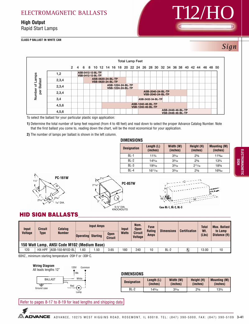
Sign
3-41
T12/HOCLASS P BALLAST IN WHITE CAN
ELECTROMAGNETIC
SIGNELECTROMAGNETIC BALLASTSHigh OutputRapid Start Lamps
A D V A N C E , 1 0 2 7 5 W E S T H I G G I N S R O A D , R O S E M O N T, I L 6 0 0 1 8 . T E L : ( 8 4 7 ) 3 9 0 - 5 0 0 0 , F A X : ( 8 4 7 ) 3 9 0 - 5 1 0 9
Refer to pages 8-17 to 8-19 for lead lengths and shipping data
HID SIGN BALLASTS___________________________________________________________Case BL-1, BL-2, BL-3
LW
H
M2"
C
To select the ballast for your particular plastic sign application:
1) Determine the total number of lamp feet required (from 4 to 48 feet) and read down to select the proper Advance Catalog Number. Notethat the first ballast you come to, reading down the chart, will be the most economical for your application.
2) The number of lamps per ballast is shown in the left column.
Ground case
120V Common
Blk
White
Red
Lamp
BALLAST
Wiring DiagramAll leads lengths 12”
60HZ., minimum starting temperature -20Þ F or -30Þ C.
PC-161W
PC-857W
150 Watt Lamp, ANSI Code M102 (Medium Base)ASB-150-M102-BLHX-HPF120 1.60 1.50 3.65 180 240 10 BL-2 13.00 10
CatalogNumber
CircuitType
InputVoltage
Input AmpsInputWatts
Nom.Open
CircuitVoltage
FuseRatingAmps
TotalWt.
(Lbs)
Max. Ballastto Lamp
Distance (ft)Dimensions
Starting OpenCircuitOperating
Certification
DIMENSIONS
Designation Length (L)(inches)
Width (W)(inches)
Height (H)(inches)
Mounting (M)(inches)
BL-2 14⁵�₁₆ 2⁵�₈ 13³�₄3³�₁₆
ASB-1240-46-BL-TPVSB-1240-46-BL-TP
Num
ber
of
Lam
ps
per
Bal
last ASB-0620-24-BL-TP
VSB-0620-24-BL-TPASB-1224-24-BL-TPVSB-1224-24-BL-TP
ASB-2448-46-BL-TPVSB-2448-46-BL-TP
ASB-0412-12-BL-TPVSB-0412-12-BL-TP
Total Lamp Feet
2 4 6 8 10 12 14 16 18 20 22 24 26 28 30 32 34 36 38 40 42 44 46 48 50
1,2
2,3,4
2,3,4
2,3,4
3,4
4,5,6
4,5,6
ASB-2432-34-BL-TP
ASB-2040-24-BL-TPVSB-2040-24-BL-TP
Designation Length (L)(inches)
Width (W)(inches)
Height (H)(inches)
Mounting (M)(inches)
BL-1 11³�₄ 3³�₁₆ 2⁵�₈ 11⁹�₆₄
BL-2 14⁵�₁₆ 3³�₁₆ 2⁵�₈ 13³�₄
BL-3 19³�₁₆ 3³�₁₆ 2¹¹�₁₆ 18⁵�₈
DIMENSIONS
BL-4 16¹¹�₁₆ 3³�₁₆ 2⁵�₈ 16⁹�₆₄

ELEC
TRON
IC H
ID
A D V A N C E , 1 0 2 7 5 W E S T H I G G I N S R O A D , R O S E M O N T, I L 6 0 0 1 8 . T E L : ( 8 4 7 ) 3 9 0 - 5 0 0 0 , F A X : ( 8 4 7 ) 3 9 0 - 5 1 0 9
ELECTRONIC HID BALLASTS

ELECTRONIC HIDELECTRONIC HID BALLASTS
A D V A N C E , 1 0 2 7 5 W E S T H I G G I N S R O A D , R O S E M O N T, I L 6 0 0 1 8 . T E L : ( 8 4 7 ) 3 9 0 - 5 0 0 0 , F A X : ( 8 4 7 ) 3 9 0 - 5 1 0 9 4-1
Contents
General Information............................................................................4-2
e-Vision®...................................................................................4-3 to 4-7
DynaVision™ ..........................................................................4-8 to 4-10
Corporate Offices(800) 322-2086
Customer Support/Technical Service(800) 372-3331 • (+) 1 847 390-5000 (International)
Visit our web site at www.advancetransformer.com
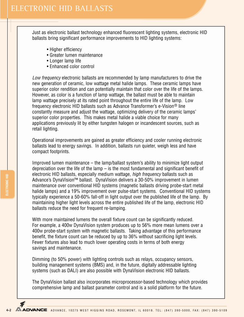
ELEC
TRON
IC H
ID
A D V A N C E , 1 0 2 7 5 W E S T H I G G I N S R O A D , R O S E M O N T, I L 6 0 0 1 8 . T E L : ( 8 4 7 ) 3 9 0 - 5 0 0 0 , F A X : ( 8 4 7 ) 3 9 0 - 5 1 0 94-2
ELECTRONIC HID BALLASTS
Just as electronic ballast technology enhanced fluorescent lighting systems, electronic HID ballasts bring significant performance improvements to HID lighting systems:
• Higher efficiency• Greater lumen maintenance• Longer lamp life• Enhanced color control
Low frequency electronic ballasts are recommended by lamp manufacturers to drive thenew generation of ceramic, low wattage metal halide lamps. These ceramic lamps havesuperior color rendition and can potentially maintain that color over the life of the lamps.However, as color is a function of lamp wattage, the ballast must be able to maintain lamp wattage precisely at its rated point throughout the entire life of the lamp. Low frequency electronic HID ballasts such as Advance Transformer’s e-Vision® line constantly measure and adjust the wattage, optimizing delivery of the ceramic lamps’ superior color properties. This makes metal halide a viable choice for many applications previously lit by either tungsten halogen or incandescent sources, such as retail lighting.
Operational improvements are gained as greater efficiency and cooler running electronicballasts lead to energy savings. In addition, ballasts run quieter, weigh less and have compact footprints.
Improved lumen maintenance – the lamp/ballast system’s ability to minimize light output depreciation over the life of the lamp – is the most fundamental and significant benefit of electronic HID ballasts, especially medium wattage, high frequency ballasts such asAdvance’s DynaVision™ ballast. DynaVision delivers a 30-50% improvement in lumenmaintenance over conventional HID systems (magnetic ballasts driving probe-start metalhalide lamps) and a 19% improvement over pulse-start systems. Conventional HID systemstypically experience a 50-60% fall-off in light output over the published life of the lamp. Bymaintaining higher light levels across the entire published life of the lamp, electronic HIDballasts reduce the need for frequent re-lamping.
With more maintained lumens the overall fixture count can be significantly reduced. For example, a 400w DynaVision system produces up to 56% more mean lumens over a400w probe-start system with magnetic ballasts. Taking advantage of this performancebenefit, the fixture count can be reduced by up to 36% without sacrificing light levels.Fewer fixtures also lead to much lower operating costs in terms of both energy savings and maintenance.
Dimming (to 50% power) with lighting controls such as relays, occupancy sensors,building management systems (BMS) and, in the future, digitally addressable lighting systems (such as DALI) are also possible with DynaVision electronic HID ballasts.
The DynaVision ballast also incorporates microprocessor-based technology which providescomprehensive lamp and ballast parameter control and is a solid platform for the future.

ELECTRONIC HIDe-Vision
®e-Vision® LOW FREQUENCY ELECTRONIC HID BALLASTS
For Low Wattage HID Lamps
A D V A N C E , 1 0 2 7 5 W E S T H I G G I N S R O A D , R O S E M O N T, I L 6 0 0 1 8 . T E L : ( 8 4 7 ) 3 9 0 - 5 0 0 0 , F A X : ( 8 4 7 ) 3 9 0 - 5 1 0 9 4-3
e-Vision Electronic Ballast Catalog Number Explanation
MH _ ––I 100 BLSA
Input Voltage:
I = Intellivolt (accepts input of 120 thru 277V, 50/60 Hz nominal) R = 120V, 50/60 Hz nominal)
Primary Lamp Type:
MH = Metal Halide
WSN = Mini whiteSON (100W ONLY)
SN = High Pressure Sodium
Maximum Lamp Wattage
20 = 22W Lamp (Philips MiniMaster Color Lamp) 39 = 39W Lamp 50 = 50W Lamp 70W = 70W Lamp
100 = 100W Lamp 150 = 100W Lamp 175 = 175W Lamp 200W = 200W Lamp
(Some ballasts are dual voltage - See product table)
Can Material / Size: (Dimensions include mounting feet)
A = Metal case with dim. 5.5” L x 3.6” W x 1.5” H G = Metal case with dim. 3.9” L x 3.0” W x 1.2” H
C = Metal case with dim. 8.0” L x 3.6” W x 1.5” H H = Metal case with dim. 6.4” L x 3.7” W x 1.5” H
D = Metal case with dim. 5.0” L x 3.0” W x 1.5” H J = Metal case with dim. 5.9” L x 1.8” W x 1.2” H
E = Metal case with dim. 5.5” L x 1.75” W x 1.2” H K = Metal case with dim. 4.75” L x 1.3” W x 1.2” H
Lead Exit / Mounting Options:
BLS = Bottom Leads with Studs
LF = Leads (side exit) with mounting Feet
LFS = Leads (side exit, lead exit from same end) with mounting Feet (RMH-39-K Only)
Key BenefitsKey Features
IntelliVolt®• Operates on either 120 or 277 volts, or any
voltage in between, 50 or 60 Hz
Smaller and lighter weight than magnetic HID F-Can ballasts
Reduced input watts compared to magnetic systems
Low frequency lamp operation
Square wave output waveform
Lamp EOL detection; Safely shuts down system atlamp end of life
Thermally protected, internally fused, and outputshort circuit protected
Excellent lamp wattage regulation• Lamp wattage will change less than .5% with a
+/-10% change in line voltage
Metallic enclosure
1.0 Ballast Factor
• Fewer SKUs required in inventory• Broadens the range of applications
• Compact electronic HID footprints• Provides greater design flexibility
• Energy Savings; Lower cost of ownership
• Prevents acoustic resonance in the lamp arc tube• Recommended by lamp manufacturers
• Maximizes lamp life
• Enhanced safety
• Safely shuts system down upon abnormal failure or conditions
Better light quality• Optimizes lamp color stability over life• Reduces lamp-to-lamp color variations
both initially and during lamp life
• Provides enhanced capability for high ambienttemperatures by transferring heat away from sensitive internal components
• Lamp produces maximum light output over it’sentire life.
ZT –
Dimming Scheme: Blank = Fixed Light Output ZT = 0-10V Dimming
–
Number of Lamps: Blank = 1 Lamp Operations 2 = (2) Lamp Operation

ELEC
TRON
IC H
IDe-
Visi
on®
A D V A N C E , 1 0 2 7 5 W E S T H I G G I N S R O A D , R O S E M O N T, I L 6 0 0 1 8 . T E L : ( 8 4 7 ) 3 9 0 - 5 0 0 0 , F A X : ( 8 4 7 ) 3 9 0 - 5 1 0 9
e-Vision® LOW FREQUENCY ELECTRONIC HID BALLASTSFor Low Wattage HID Lamps
4-4
e-Vision® Electronic Ballast Specifications
Section 1 - Physical Characteristics
1.0 The electronic ballast shall be furnished with integral, color-coded leads.
Section II - Performance Requirements
2.0 The electronic ballast shall be IntelliVolt® and operate from anominal line voltage range of 120-277 volts, +/-10%, 50/60 Hz.
2.1 The electronic ballast input current shall have Total HarmonicDistortion (THD) of less than 15%.
2.2 The electronic ballast shall have a Power Factor greater than 90%.
2.3 The electronic ballast shall have a lamp end-of-life detectionand shutdown circuit.
2.4 The electronic ballast shall be Sound Rated A.
2.5 The electronic ballast output frequency to the lamps shall beless than 200 Hz to prevent acoustic resonance inside the lamparc tube and to minimize visible flicker.
2.6 The electronic ballast shall provide a “Lamp Current CrestFactor” of less than 1.5.
2.7 The electronic ballast shall be thermally protected to shut offwhen operating temperatures reach unacceptable levels.
Section III - Regulatory Requirements
3.0 The electronic ballast shall meet the requirements of the FederalCommunications Commission rules and regulations, Title 47 CFRpart 18, for Non-Consumer equipment.
3.1 The electronic ballast shall be Underwriters Laboratories (UL)Listed and CSA Certified where applicable.
Section IV - Other
4.0 The electronic ballast shall not contain Polychlorinated Biphenyl(PCB’s).
4.1 The electronic ballast shall carry a three-year warranty from thedate of manufacture for operation at marked maximum case temperature or less.
4.2 The manufacturer shall have a twenty-five year history of produc-ing HID lamp ballasts for the North American market.
4.3 The electronic ballast shall be produced in a factory certified toISO 9002 Quality System Standards
Installation Notes1. Red lead must be connected to center terminal of lamp (for Edison. screw base lamps). Do not connect red or blue lead to neutral or ground.2. Use 4.0 kV pulse rated lampholder. (Except where special lampholder is required, such as 22W Philips Mini MasterColor Lamp).3. Maximum ballast-to-lamp distance is 5 ft. using typical wiring methods and materials. Additional distance up to 15 ft. may be possible using
wire between lamp and ballast with a total measured capacitance of 100 picofarads or less. Consult Advance for application assistance.4. Power mains must be cycled off and then on to reset ballast after failed lamps are replaced.
Ballast Hot Spot LocationHot spot locations differ with each ballast model and are designated on the individual ballast labels. Consult ballast labels and ballastspecification sheets for Hot Spot locations.
Enclosure Dimensions, Lead Lengths and Wiring Diagrams
(Blue)
Ballast
(Black)
(White)
(Red)
Com120V - 277V
Ballast Case must
be Grounded
Lamp
(White/Black)
(Blue)
Ballast(Black)
(White)
(Red)
Com
120V - 277V
Ballast Case must
be Grounded
Lamp
(Green)
(Blue)
Ballast
(Black)
(White)
(Red)
Com
120V
Ballast Case must
be Grounded
Lamp
kV
(Blue)
Ballast
(Black)
(White)
(Red)
Com
120V - 277V
Ballast Case mustbe Grounded
(Green)
Lamp 1
Lamp 2(Orange)
(Brown)
kV
kV
Ballast
(Black)
(White) Com
120V - 277V
Ballast Case mustbe Grounded
(Blue)
(Red)
Lamp
(Gray)
(Violet) Dim +
Dim -
Fig 1 Fig 2 Fig 3
Fig 4Fig 5
Fig 6

Metal Halide and High Pressure Sodium
ELECTRONIC HIDe-Vision
®e-Vision® LOW FREQUENCY ELECTRONIC HID BALLASTS
For Low Wattage HID Lamps
A D V A N C E , 1 0 2 7 5 W E S T H I G G I N S R O A D , R O S E M O N T, I L 6 0 0 1 8 . T E L : ( 8 4 7 ) 3 9 0 - 5 0 0 0 , F A X : ( 8 4 7 ) 3 9 0 - 5 1 0 9 4-5
* Ordering information:–LF Side exit leads with mounting feet–BLS Bottom exit leads with mounting studs
Black Input Power 11.0” +/- 1.0” 9.0” +3.0”/-2.0” 0.5”White Input Power 11.0” +/- 1.0” 9.0” +3.0”/-2.0” 0.5”
Black/White Lamp Power Selection (IMH models only) 11.0” +/- 1.0” 9.0” +3.0”/-2.0” 0.5”Red Lamp Base 11.0” +/- 1.0” 9.0” +3.0”/-2.0” 0.5”Blue Lamp Screwshell 11.0” +/- 1.0” 9.0” +3.0”/-2.0” 0.5”
Function Lengths Lead Lengths Length StripWire Color
(-LF model) (-BLS model)
22 Watt Lamp, Philips Mini MasterColor, ANSI Code M175, Minimum Starting Temp. -20°C/-4°F
InputVolts
Catalog Number* Note 1
Certifications LineCurrent(Amps)
InputPowerANSI
(Watts)
Max.Case
Temp.Note 6
WiringDiag. Fig. Weight
(lb)WattsNumber
Lamp Data
RMH-20-E-LFRMH-20-E-BLS
✓ ✓ 0.23 41 22 120 26 70°C E 0.4
39 Watt Lamp, ANSI Code M130, Minimum Starting Temp. -30°C/-20°FRMH-39-K-LF orRMH-39-K-LFS
Note 2✓ ✓ 0.40 41 39 120 45 90°C K 0.5
IMH-39-G-LF orIMG-39-G-BLS
✓ ✓
✓ ✓1 39 120
2770.39
30.18
4690°C
45G 0.9
Max.Distance toLamp (ft)
6
6
5
New
New
New
IMH-39-J-LF✓ ✓
✓ ✓1 39 120
2770.39
30.18
4690°C
45J 0.9 5New
IMH-50-A-LF orIMH-50-A-BLS
Note 3
✓ ✓
✓ ✓1 39 120
2770.38
10.16
4585°C
44A 1.4 5
IMH-239-A-LF orIMG-239-A-BLS
✓ ✓
✓ ✓2 39 120
2770.74
50.31
8985°C
89A 1.7 6New
50 Watt Lamp, ANSI Code M110, Minimum Starting Temp. -30°C/-20°FIMH-50-A-LF orIMH-50-A-BLS
Note 3
✓ ✓
✓ ✓1 50 120
2770.47
20.20
5685°C
55A 1.4 5
70 Watt Lamp, ANSI Code M98 or M143 or M139, Minimum Starting Temp. -30°C/-20°FIMH-70-G-LF orIMG-70-G-BLS
✓ ✓
✓ ✓1 70 120
2770.67
30.30
8090°C
79G 0.9 5New
IMH-70-J-LF✓ ✓
✓ ✓1 70 120
2770.67
30.30
8090°C
79J 0.9 5New
IMH-70-D-LF orIMH-70-D-BLS
✓ ✓
✓ ✓1 70 120
2770.67
30.29
8085°C
79D 1.6 5
IMH-100-A-LF orIMG-100-A-BLS
Note 4
✓ ✓
✓ ✓1 70 120
2770.68
10.30
8285°C
81A 1.4 5
New
Notes:1. All ballasts are sound rated A, and feature high power factor (>0.9, a ballast factor of 1.0 resettable thermal protection, and a maximum Harmonic Distortion of 15%.2. For RMH-39-K-LF, input and output lead wires exit on opposite sides of ballast. For RMH-39-K-LFS, all lead wires exit the same side of the ballast.3. A dual-wattage ballast for 39W or 50W MH4. A dual-wattage ballast for 70W or 100W MH5. A dual-wattage ballast for 150W or 175W MH6. Maximum case temperature should not be exceeded in the application, as life will be affected and the integral re-settable thermal protector may activate. A lower
maximum temperature rating does not imply lesser thermal performance, and can be indicative of a cooler running ballast design. Consult factory for further application assistance.
7. Also operates (1) 150W HPS S56 (100V) Lamp
Green Ground 11.0” +/- 1.0” 9.0” +3.0”/-2.0” 0.5”Orange Lamp Base 11.0” +/- 1.0” 9.0” +3.0”/-2.0” 0.5”Brown Lamp Screwshell 11.0” +/- 1.0” 9.0” +3.0”/-2.0” 0.5”
For ballast diagrams see page 4-7

ELEC
TRON
IC H
IDe-
VISI
ON™
A D V A N C E , 1 0 2 7 5 W E S T H I G G I N S R O A D , R O S E M O N T, I L 6 0 0 1 8 . T E L : ( 8 4 7 ) 3 9 0 - 5 0 0 0 , F A X : ( 8 4 7 ) 3 9 0 - 5 1 0 9
e-Vision™ LOW FREQUENCY ELECTRONIC HID BALLASTSFor Low Wattage Metal Halide Lamps
4-6
Metal Halide and High Pressure Sodium
* Ordering information:–LF Side exit leads with
mounting feet–BLS Bottom exit leads with
mounting studs
Black Input Power 11.0” +/- 1.0” 9.0” +3.0”/-2.0” 0.5”White Input Power 11.0” +/- 1.0” 9.0” +3.0”/-2.0” 0.5”
Black/White Lamp Power Selection (IMH models only) 11.0” +/- 1.0” 9.0” +3.0”/-2.0” 0.5”Red Lamp Base 11.0” +/- 1.0” 9.0” +3.0”/-2.0” 0.5”Blue Lamp Screwshell 11.0” +/- 1.0” 9.0” +3.0”/-2.0” 0.5”
Function Lengths Lead Lengths Length StripWire Color
(-LF model) (-BLS model)
InputVolts
Catalog Number* Note 1
Certifications LineCurrent(Amps)
InputPowerANSI
(Watts)
Max.Case
Temp.Note 6
WiringDiag. Fig. Weight
(lb)WattsNumber
Lamp Data
100 Watt Lamp, ANSI Code M90 or M140, Minimum Starting Temp. -30°C/-20°FIMH-100-D-LF orIMG-100-D-BLS
✓ ✓
✓ ✓1 100 120
2770.92
30.40
11085°C
109D 1.6
Max.Distance toLamp (ft)
5New
IMH-100-A-LF orIMH-100-A-BLS
Note 4
✓ ✓
✓ ✓1 100 120
2770.93
20.40
11285°C
110A 1.4 5
175 Watt Pulse Start Lamp, ANSI Code M137 or M152 (Pulse Start), Minimum Starting Temp. -30°C/-20°FIMH-175-C-LF orIMH-175-C-BLS
Note 5
✓ ✓
✓ ✓1 175 120
2771.7
20.7
19485°C
191C 2.5 5
Notes:1. All ballasts are sound rated A, and feature high power factor (>0.9, a ballast factor of 1.0 resettable thermal protection, and a maximum Harmonic Distortion of 15%.2. For RMH-39-K-LF, input and output lead wires exit on opposite sides of ballast. For RMH-39-K-LFS, all lead wires exit the same side of the ballast.3. A dual-wattage ballast for 39W or 50W MH4. A dual-wattage ballast for 70W or 100W MH5. A dual-wattage ballast for 150W or 175W MH6. Maximum case temperature should not be exceeded in the application, as life will be affected and the integral re-settable thermal protector may activate. A lower
maximum temperature rating does not imply lesser thermal performance, and can be indicative of a cooler running ballast design. Consult factory for further application assistance.
7. Also operates (1) 150W HPS S56 (100V) Lamp
Green Ground 11.0” +/- 1.0” 9.0” +3.0”/-2.0” 0.5”Orange Lamp Base 11.0” +/- 1.0” 9.0” +3.0”/-2.0” 0.5”Brown Lamp Screwshell 11.0” +/- 1.0” 9.0” +3.0”/-2.0” 0.5”
For ballast diagrams see page 4-7
150 Watt Lamp, ANSI Code M102 or M142, Minimum Starting Temp. -30°C/-20°FIMH-150-H-LF orIMG-150-H-BLS
✓ ✓
✓ ✓1 150 120
2771.4
30.6
16585°C
161H 1.9 5New
IMH-175-C-LF orIMH-175-C-BLS
Note 5,7
✓ ✓
✓ ✓1 150 120
2771.4
10.6
16985°C
166C 2.5 5
200 Watt Pulse Start Lamp, ANSI Code M136 (Pulse Start), Minimum Starting Temp. -30°C/-20°F
IMH-200-C-LF ✓ ✓1 200 120277
2.03
1.0
22985°C
219C 2.5 5
100 Watt Lamp, Philips Mini whiteSON (SDW-TG), ANSI Code S167 (Pulse Start), Min. Starting Temp. -20°C/-4°F
IWSN-150-C-LF orIWSN-150-C-BLS
✓ ✓
✓ ✓1 150 120
2770.9
30.5
16585°C
161C 1.9 5
InputVolts
Catalog Number* Note 1
Certifications LineCurrent(Amps)
InputPowerANSI
(Watts)
Max.Case
Temp.Note 6
WiringDiag. Fig. Weight
(lb)WattsNumber
Lamp Data Max.Distance toLamp (ft)
150 Watt Lamp, ANSI Code M102 or M142, Minimum Starting Temp. -30°C/-20°F
IZTMH-150-C-LF✓ ✓
✓ ✓1 150 120
2771.4
60.6
16985°C
166C 2.5 5
150 Watt HPS Lamp, ANSI Code S56 (100V), Minimum Starting Temp. -30°C/-20°F
IZTSN-150-C-LF✓ ✓
✓ ✓1 150 120
2771.4
60.6
16985°C
166C 2.5 5
CONTROLLABLE BALLASTS WITH 0-10V DIMMING INTERFACE Note 8
New
New

ELECTRONIC HIDe-VISION™
e-Vision™ LOW FREQUENCY ELECTRONIC HID BALLASTSFor Low Wattage Metal Halide Lamps
A D V A N C E , 1 0 2 7 5 W E S T H I G G I N S R O A D , R O S E M O N T, I L 6 0 0 1 8 . T E L : ( 8 4 7 ) 3 9 0 - 5 0 0 0 , F A X : ( 8 4 7 ) 3 9 0 - 5 1 0 9 4-7
CaseFigure
OverallLength
CaseLength
CaseWidth
HeightMountingLength
MountingWidth
A 140mm[5.5"]
120mm[4.7"]
92mm[3.6"]
38mm[1.5"]
132mm[5.2"]
73mm[2.9"]
C 204mm[8.0"]
184mm[7.2"]
92mm[3.6"]
38mm[1.5"]
195mm[7.7"]
73mm[2.9"]
H 161mm[6.3"]
144mm[5.7"]
92mm[3.6"]
38mm[1.5"]
152mm[6.0"]
73mm[2.9"]
CaseFigure
OverallLength
CaseLength
CaseWidth
HeightMountingLength
MountingWidth
D 128mm[5.0"]
108mm[4.3"]
77mm[3.0"]
38mm[1.5"]
118mm[4.6"]
19mm[0.7"]
CaseFigure
OverallLength
CaseLength
CaseWidth
HeightMountingLength
MountingWidth
E 140mm[5.5"]
127mm[5.0"]
44mm[1.7"]
30mm[1.2"]
135mm[5.3"]
26mm[1.0"]
J 149mm[5.9"]
140mm[5.5"]
46mm[1.8"]
30mm[1.2"]
145mm[5.7"]
27mm[1.0"]
CaseFigure
OverallLength
CaseLength
CaseWidth
HeightMountingLength
MountingWidth
G 97mm[3.8"]
90mm[3.5"]
77mm[3.0"]
30mm[1.2"]
87mm[3.4"]
67mm[2.6"]
CaseFigure
OverallLength
CaseLength
CaseWidth
HeightMountingLength
MountingWidth
K 113mm[4.4"]
104mm[4.1"]
33mm[1.1"]
30mm[1.2"]
13.5mm[0.5"]
114mm[4.5"]

ELEC
TRON
IC H
IDDY
NAVI
SION
A D V A N C E , 1 0 2 7 5 W E S T H I G G I N S R O A D , R O S E M O N T, I L 6 0 0 1 8 . T E L : ( 8 4 7 ) 3 9 0 - 5 0 0 0 , F A X : ( 8 4 7 ) 3 9 0 - 5 1 0 94-8
DYNAVISION™ ELECTRONIC HID BALLASTS
DynaVision extends the key benefitsof magnetic pulse-start metal halidesystems — energy efficiency andwhite light. With its very-high frequency operation, as well as its on-board microprocessor andstandard features, DynaVision provides numerous additionalbenefits and advantages.
DynaVision Features Benefits and Advantages
Microprocessor technology Lower operating and maintenance costsHigh frequency operation Fewer fixturesTrue constant wattage Energy savings
320/350/400 Tri-WattageFewer SKU’sLess chance for error
IntelliVolt 200-277V 50/60 Hz Ease of change overto different wattage lamps
Standby-lighting readyIntegral 120V quartz tap No special orders
and relay, 250W No special relay or control required
0-10V dimming with automatic Continuous dimming down to 50% power
15-minute warm upAdditional energy savings through
daylight harvesting and occupancy sensing
0º to 55ºC ambient rating standard Greater reliability, flexibility and -40º to +40ºC ambient rating optional and applications opportunities
Lamp End-of-Life Protection (EOL) Safety
More about...Standby Lighting Versatility Controllability
DynaVision’s 120-volt output is designedto operate one quartz (incandescent)standby lamp up to 250W. The quartzlamp on or off modes are determined by theHID lamp’s specific operating conditions.Once the HID lamp strikes, the quartz lampautomatically switches off when the HIDlamp reaches 50% power.
DynaVision is dimmable – down to 50% of nominal lamppower, with no noticeable loss in color characteristics.With 0-10V dimming, and compatible with a host ofproducts from most control manufacturers, DynaVisionbrings new flexibility and energy-saving strategies,such as daylight harvesting and occupancy sensing, toapplications in the industrial, educational, government,hospitality, commercial and retail sectors.
DynaVision™ Electronic BallastCatalog Number Breakdown
IZTEMH4003PS - XJBasic Model Number
Options
I = IntelliVolt (200-277 50/60 Hz)
ZT = Zero-to-ten volt dimming
E = Electronic
MH = Metal Halide
400 = 400W maximum
3 = 3 wattage capability (320/350/400W)
PS = Pulse-Start
-XJ = Without junction box (i.e. junction box is included if this suffix is omitted).
F = Low temperature version (-40ºC to+55ºC)
9.2˝ bracket end-to-end length
Optionaljunction box
Fully closedextruded aluminumhousing with white finish
8.8˝ mountingdimensions
4.4˝ mountingdimensions
DIP switch accessfor lamp wattage selection
5mm mountingholes (4) for#10 screws
Integral mounting brackets
Hot spot measurementlocation at screw
4.0˝
2.3˝
3.7˝
8.0˝
2.6˝5.0˝
Physical Characteristics

ELECTRONIC HIDDYNAVISION
DYNAVISION™ ELECTRONIC HID BALLASTS
A D V A N C E , 1 0 2 7 5 W E S T H I G G I N S R O A D , R O S E M O N T, I L 6 0 0 1 8 . T E L : ( 8 4 7 ) 3 9 0 - 5 0 0 0 , F A X : ( 8 4 7 ) 3 9 0 - 5 1 0 9 4-9
1. Red lead must be connected to center terminal of lamp. Do not connect red or blue lead to line neutral.
2. Setting precaution with triple-wattage feature: Do not operatelower wattage lamp on a ballast which has been set for operation of higher wattage lamp. Short lamp life may result.
3. Ballast output will shut off after 40 minutes maximum if lamp does not successfully ignite. Replace lamp and cycle mains torestore output.
4. Use 4.0 kV pulse rated lampholder.
5. Connect red lamp lead to 600Vrms, 3.5kV or UL style 1452 wire.
6. Remote mounting distances not exceeding 15 ft. are possible withnormal wiring methods. For distances greater than 15 ft., powerlosses in the wire can result in appreciable decline in actual lampoperating power. Consult Advance for application assistance.
7. Mains must be cycled after replacing lamp.
8. Ballast output exceeds 100kHz. Suitable test equipment is requiredfor measurement.
9. Ballast is suitable for recessed use. Do not install insulation above orwithin 3” of ballast sides.
Where to Measure the Ballast Hot Spot
Section I – Physical Characteristics
1.1 The electronic ballast shall be fully enclosed in an aluminumhousing painted white.
1.2 The aluminum housing shall include a divided wiring compartmentto separate the power leads from the control leads. All leads to becolor-coded.
Section II – Performance Requirements
2.1 The electronic ballast shall be multivoltage capable and operatefrom a line voltage range of 180 – 305 volts, 50/60 Hz.
2.2 The electronic ballast shall incorporate a microprocessor controllerto provide for optimum starting and operation of the HID lamp.
2.3 The electronic ballast input current shall have Total HarmonicDistortion (THD) of less than 15% when operated at nominal linevoltage (200V, 208V, 230V, 240V, 277V).
2.4 The ballast shall incorporate a 0-10V dimming interface and control the dimming function such that the HID lamp is allowedto warm up for fifteen minutes at full power before the lamp willbe allowed to dim, regardless of the level of the 0-10V signal. 10V applied to the dimming control leads, shall result in full light output. 0V applied, or shorting the control leads together,shall result in dimming to 50% of nominal lamp power.
2.5 The ballast shall include a 120V/250W auxiliary output for stand-byincandescent lighting that shall include an integral control to turnthe auxiliary lamp on and off. The integral control shall include atime-delay feature to keep the auxiliary lamp on until the HIDlamp reaches 50% power.
2.6 The electronic ballast shall have a Power Factor greater than 90%.
2.7 The electronic ballast shall have a lamp end-of-life detection andshutdown circuit.
2.8 The electronic ballast shall be Sound Rated A.
2.9 The electronic ballast output frequency to the lamps shall behigher than 100 kHz to prevent acoustic resonance inside thelamp arc tube and to minimize visible flicker.
2.10 The electronic ballast shall be thermally protected to shut offwhen operating temperatures reach unacceptable levels.
Section III – Regulatory Requirements
3.1 The electronic ballast shall meet the requirements of the FederalCommunications Commission rules and regulations, Title 47 CFRpart 18, for Non-Consumer equipment.
3.2 The electronic ballast shall be Underwriters Laboratories (UL)Listed and CSA Certified where applicable.
Section VI – Other
4.1 The electronic ballast shall not contain Polychlorinated Biphenyl(PCB’s).
4.2 The electronic ballast shall carry a three-year warranty from thedate of manufacture for operation at an ambient temperature of55° C or less and when operated as a stand alone product(i.e.remotely from a lighting fixture housing). When operatedwithin a lighting fixture housing, the same three-year warrantyshall apply for a maximum ballast case hot spot temperature of76° C or less.
4.3 The manufacturer shall have a twenty-five year history of producingHID lamp ballasts for the North American market.
4.4 The electronic ballast shall be produced in a factory certified to ISO 9002 Quality System Standards.
DynaVision Electronic Ballast Specifications
Installation and Application Notes
Side View
Optionaljunction box
Hot spot at forward screw location

ELEC
TRON
IC H
IDDY
NAVI
SION
A D V A N C E , 1 0 2 7 5 W E S T H I G G I N S R O A D , R O S E M O N T, I L 6 0 0 1 8 . T E L : ( 8 4 7 ) 3 9 0 - 5 0 0 0 , F A X : ( 8 4 7 ) 3 9 0 - 5 1 0 9
DYNAVISION™ ELECTRONIC HID BALLASTS
4-10
Breaks New Ground in HID Performance
Min Input Max. Min. DIPLamp Data Start Input Catalog Listings Line Power Ballast THD PF Switch
Temp. Volts Number Current ANSI Factor % % SettingsNo. Watts (F/C) (A) (W)
320 Watt Lamp, ANSI Code M132/M154
1 320 32/0 200 to IZTEMH4003PS 1.8 @ 200V 345 1.0 15 90-40/-40 277 IZTEMH4003PS-F 1.3 @ 277V
350 Watt Lamp, ANSI Code M131
1 350 32/0 200 to IZTEMH4003PS 1.9 @ 200V 375 1.0 15 90-40/-40 277 IZTEM4003PS-F 1.4 @ 277V
400 Watt Lamp, ANSI Code M135/M155
1 400 32/0 200 to IZTEMH4003PS 2.2 @ 200V 430 1.0 15 90-40/-40 277 IZTEM400EPS-F 1.6 @ 277V
With an integral, industry-standard 0-10V interface, theDynaVision™ electronic ballasts offer the capability to dimthe lamp by lowering the wattage lamp, reducing energyconsumption of the light fixture by up to 50%. Access tothis interface is via the violet (+) and grey (-) dimmingcontrol leads. These leads can be connected to either a 0-10V dimming control, (DynaVision ballast are compatiblewith standard 0-10V control devices available from manymanufacturers) a 0-10V DC power supply, or with a switch.An open switch provides full lamp power, and a closedswitch, short-circuiting the 0-10V wires, yields 50% lamppower. Control devices such as relays and occupancy sen-sors may also be used.
A potentiometer may also be used. However, the value ofthe potentiometer is dependent on the number of ballastsconnected. Consult Advance for guidance.
Application SpecificationsPulse-Start Metal Halide
Wire Color FunctionBlack Input Power
White Input Power
Green Ground
Red Lamp Eyelet
Blue Lamp Screwshell
Yellow (2) 120V Lamp Output
Violet 0-10V Dimming (+)
Grey 0-10V Dimming (-)
Lead Wire Information
All lead lengths are 11" +/- 1". The black & white(input power), green(ground), and red &blue (lamp) leads arepre-stripped 1/2". The two yellow 120v(output) and violet & grey (dimmingcontrol) leads haveinsulated ends.
Preset at Factory
DIP switches are “on” in the down position
ON
ON
ON
NOTE: These specifications apply to operation of pulse-start metal halide lamps with quartz arc-tube construction only.For operating compatibility with ceramic arc-tube lamps, consult Advance.
Dimming FeatureIn accordance with the requirements of the HIDlamp manufacturers and NEMA, the dimming featureincludes a time delay to allow the HID lamp towarm up for 15 minutes at full power before thelamps will be allowed to dim, regardless of the levelof the 0-10V signal.
New
New
New

HID
A D V A N C E , 1 0 2 7 5 W E S T H I G G I N S R O A D , R O S E M O N T, I L 6 0 0 1 8 . T E L : ( 8 4 7 ) 3 9 0 - 5 0 0 0 , F A X : ( 8 4 7 ) 3 9 0 - 5 1 0 9
HIGH INTENSITY DISCHARGE BALLASTS

HIDHIGH INTENSITY DISCHARGE BALLASTS
A D V A N C E , 1 0 2 7 5 W E S T H I G G I N S R O A D , R O S E M O N T, I L 6 0 0 1 8 . T E L : ( 8 4 7 ) 3 9 0 - 5 0 0 0 , F A X : ( 8 4 7 ) 3 9 0 - 5 1 0 9 5-1
Customer Support/Technical Service(800) 372-3331 • (+) 1 847 390-5000 (International)
Visit our web site at www.advancetransformer.com
Contents
General Information .................................................................5-2 to 5-3
Core & Coil Ballast HID Replacement Kits..............................5-4 to 5-7
EEI-NEMA Head Ballasts.....................................................................5-8
Core & Coil Ballast HID Replacement Kits (Canada) ........................5-9
Val-U-Pak Replacement Kits ............................................................5-10
Val-U-Pak Plus Ballast/Lamp Replacement Kits .............................5-11
Core & Coil Ballasts 71A Series (60 Hz)Mercury..........................................................................5-14 to 5-17
Metal Halide ...................................................................5-18 to 5-31
High Pressure Sodium ...................................................5-32 to 5-45
Low Pressure Sodium....................................................5-46 to 5-47
Capacitors for Bi-Level Operation ....................................................5-48
Non-PCB Capacitors ............................................................5-48 to 5-49
Ignitors & Ballast to Lamp Distances ..................................5-50 to 5-53
Transformers & Autotransformers ....................................................5-54
Protected Dual-Volt F-Can 72C Series.................................5-55 to 5-58Mercury — Metal Halide — High Pressure Sodium
Encapsulated Core & Coil 73B Series .................................5-59 to 5-62Mercury — Metal Halide — High Pressure Sodium
Postline Ballasts 74P Series................................................5-63 to 5-66Mercury — Metal Halide — High Pressure Sodium
Indoor Enclosed Ballasts 78E Series ...................................5-67 to 5-68Mercury — Metal Halide — High Pressure Sodium
Outdoor Weatherproof Ballasts 79W Series.......................5-69 to 5-71Mercury — Metal Halide — High Pressure Sodium
Note:For International HID Ballasts (50Hz and 60Hz), See International Section, pages 6-14 to 6-19
For Electronic HID Ballasts, See Section 4
Corporate Offices(800) 322-2086

HID
A D V A N C E , 1 0 2 7 5 W E S T H I G G I N S R O A D , R O S E M O N T, I L 6 0 0 1 8 . T E L : ( 8 4 7 ) 3 9 0 - 5 0 0 0 , F A X : ( 8 4 7 ) 3 9 0 - 5 1 0 9
HIGH INTENSITY DISCHARGE BALLASTS
5-2
ADVANCE® HID Lamp Ballasts are available to operate the wide vari-ety of mercury, metal halide, high pressure sodium and low pressuresodium lamps available in today’s marketplace.Like fluorescent, HID lamps are electric discharge lamps. Light isproduced by an arc discharge between two electrodes located atopposite ends of an arc tube within the lamp’s outer glass envelope.The ballast is the lamp’s power supply; its purpose is to provideproper starting and operating voltage and current to initiate and sus-tain this arc.
LAMP STARTINGMercury and Probe-Start Metal Halide LampsMercury and the “traditional” probe-start metal halide lamps (175through 1500 watt) have an additional electrode located at one endof the arc tube to assist in lamp starting. These types of lampsrequire an open circuit voltage (OCV) approximately two times thelamp’s operating voltage to initiate the arc.
High Pressure Sodium and Pulse-Start Metal Halide LampsHigh pressure sodium and modern metal halide lamps which includeexisting lamps, 150 watt and less, as well as the new generation ofpulse-start metal halide lamps, 150 watt and greater, have no startingelectrodes. In addition to an OCV of approximately two times the lampvoltage, these lamps utilize an “ignitor” to provide a high voltagestarting pulse directly across the main electrodes. Once the lamp’s arcis established, the ignitor automatically stops delivering pulses, andthe lamp comes up to full brightness on its own.
Low Pressure SodiumBecause they have neither a starting electrode nor an ignitor, low pres-sure sodium lamps require an open circuit voltage approximately threeto seven times the lamp voltage to start and sustain the lamp.
LAMP OPERATIONElectric discharge lamps have a negative resistance characteristicwhich causes them to draw an increasing amount of current leadingto immediate destruction if operated directly from the power line.The ballast, therefore, is utilized to limit the current to the correctlevel for proper operation of the lamp.Ballast factor is defined as the ratio of light output produced by alamp operating on a commercial ballast versus the lamp’s rated lightoutput. Advance HID ballasts have a nominal ballast factor of 1.0,thus providing full light output.HID lamps take several minutes to warm-up and reach full lumenoutput. Additionally, an interruption in the input power or a suddenvoltage drop may cause the arc to extinguish. A lamp that is hot willnot restart immediately. Before the lamp will relight, it must cool suf-ficiently to reduce the vapor pressure within the arc tube to a pointwhere the arc will restrike. The approximate warmup and restrikingtimes of the HID lamp groups are as follows:
BALLAST INPUT VOLTAGESUnlike fluorescent lighting which is operated on either 120 volt or
277 volt circuits, power for HID lighting in the U.S. is delivered at anyone of five voltages: 120V, 208V, 240V, 277V or 480V. While 120Vand 277V are the most popular, because of the heavier loads andsometimes longer runs associated with HID lighting (such as shop-ping mall parking lots), 208V and 240V power is often used insteadof 120V, and 480V instead of 277V.To address this multiplicity of voltages, the HID ballast industry offersballasts with multiple input voltage taps on the primary coil. Advance's
4-tap design is called a Quadri-Volt® ballast and operates on either 120V,208V, 240V or 277V power. There is an Advance Quadri-Volt® ballast forvirtually every HID lamp on the market. New 5-TAP™ designs, whichfeature the same input voltages as Quadri-Volt® ballasts plus 480V,are available for 250W, 400W, and 1000W metal halide and highpressure sodium applications.
FIXTURE FUSINGMany HID lighting fixtures are sold with protective fuses. The purposeof the fuse is to isolate a fixture from the lighting circuit in the eventof excessive current draw, such as might be caused by a failed bal-last. Unfortunately, the fuse will not protect the ballast from failure, asit is often the failed ballast itself that is causing the high current draw.
With many fixtures the fuse is physically located in the ballastcompartment of the fixture. The air temperature within this compart-ment can easily reach 80°C and still be within the design limitationsof the fixture.
Many fuses are temperature sensitive, meaning that the current rat-ing goes down as the ambient temperature goes up. Fuse current rat-ings are based on the fuse’s performance in a 25°C ambient (77°F). Inan 80°C ambient, some fuses will open at half their rating.
As a result, the fuse rating shown in the HID ballast tables is calcu-lated at 21/2 to 3 times the highest current draw of the ballast: lamp oper-ating, starting or open circuit conditions. Standard or slow-blow fusesshould be used. Fast-blow fuses should be avoided as ballast in-rushcurrents during power turn-on could cause these fuses to blowunnecessarily. It is not necessary to use current limiting fuses.
BALLAST DESIGN APPLICATIONSHID lamp ballasts are available in a variety of shapes and sizes forthe most popular lighting applications. Six basic designs are inwidest use today.
Core & CoilThe basic ballast is the open core & coil which is most often used as
a component within a lighting fixture. The core & coil also forms thenucleus of the five other ballast configurations detailed in this section.It consists of either one, two or three copper coils on a core (or “stack”)of electrical-grade steel laminations. The coils are assembled to coresections which are then surface-welded together. At AdvanceTransformer Co. the assembled ballast is vacuum impregnated with asilica-filled polyester varnish to re-enforce the electrical insulation, pre-clude moisture, inhibit noise, and dissipate heat. Advance utilizes avacuum-pressure impregnation process. Most other HID ballast manu-facturers apply varnish via a preheat-and-dip process which only puts athin coat of varnish on the outer surface of the ballast. Advance Core &Coil ballasts feature as standard an insulation system rated class H(180°C maximum coil hot spot temp.) for ballasts below 600 watts, andADVANCE Class N (200°C maximum coil hot spot temp.) for ballasts600 watts and higher. When performing in-fixture testing, the maximumallowable average coil temperature (measured by the rise-of-resistancemethod) is 165°C for class H ballasts or 185°C for ADVANCE Class Nballasts. The maximum allowable coil face or lead wire temperature(measured by thermocouple) is 150°C for both class H and ADVANCEClass N ballasts.
LIGHT SOURCEMercury Vapor 5-7 minutes 3-6 minutesMetal Halide (Probe-Start) 3-4 minutes 10-20 minutesMetal Halide (Pulse-Start) 2 minutes 3-4 minutesHigh Pressure Sodium 3-4 minutes 1/2-1 minuteLow Pressure Sodium 7-10 minutes 3-12 seconds
WARM-UP TIME RESTRIKE TIME
Fluorescent Can(72C Series)
Encapsulated Core & Coil(73B Series)
Indoor EnclosedRectangular Can
(78E Series)

HIDHIGH INTENSITY DISCHARGE BALLASTS
A D V A N C E , 1 0 2 7 5 W E S T H I G G I N S R O A D , R O S E M O N T, I L 6 0 0 1 8 . T E L : ( 8 4 7 ) 3 9 0 - 5 0 0 0 , F A X : ( 8 4 7 ) 3 9 0 - 5 1 0 9 5-3
Encapsulated Core & CoilWhere quiet performance is required, the standard open core & coil bal-lasts are encapsulated (potted) in a cube-shaped steel can utilizingClass H (180°C) polyester compound. These ballasts carry a Class Anoise rating up through 175 watts and Class B for 250 and 400 watts.As with the open core & coil, the capacitor (and ignitor where included)are mounted separately within the fixture.
Ballasts with Aluminum Secondary CoilAdvance offers a wide range of ballasts that have primary coil made outof copper and secondary coil made out of aluminum. All Advance bal-lasts including ballasts with aluminum secondary coil adhere to ANSIspecifications and are certified by respective agencies (UL, CSA, etc.).Aluminum ballasts are designated by -A after ballast Catalog numberand/or “AL” on wiring diagram.
Fluorescent Can (F-Can)For indoor commercial applications of HID lighting such as offices,schools and retail stores, ballast noise must be minimized. Ballasts forthese fixtures are most often encased and potted in fluorescent ballasttype cans and utilize Class A (90°C) asphalt insulating materials (thesame as used in fluorescent lamp ballasts).
The Advance line of F-can ballasts comes in two dual-voltage config-urations: 120/277 volt for the US market, and 120/347 volt for theCanadian market. Each unit has built-in, automatically resetting, ther-mal protectors which disconnect the ballast from the power line in theevent of overheating. All units are high power factor and include thecapacitor within the can. All models for high pressure sodium, low-wattage metal halide, and pulse-start metal halide lamps also includethe ignitor in the can. Spacing between ballasts and the mounting surface must be consid-ered when the ballasts are remote-mounted. Twelve inches betweenballasts must be maintained and if multiple rows vertically are used,there should be at least 12 inches between rows. In addition to ballastand row spacing, the ballast must not be directly mounted to a non-metallic surface. They must be spaced with mounting brackets (avail-able from Advance) to allow airflow under the ballast base.
Indoor EnclosedThese units are designed for use indoors where the ballast must bemounted remotely from the luminaire. They are most typically used infactories where the luminaire may be mounted in a high-bay where veryhigh ambient temperatures may be experienced. In these instances, theremotely-mounted ballast operates cooler, subsequently providinglonger life because it is away from both the heat of the ceiling ambientand lamp heat within the fixture.
The case contains the core & coil potted in a Class H (180°C) heat-dissipating resin. The capacitor(s) and ignitor are contained within aseparate compartment. Knockouts in both ends of the case facilitatehook-up in the most convenient manner. Wall mounting is accom-plished through flanges on the top and bottom of the case. The ballastis a UL Listed product.
Outdoor WeatherproofWeatherproof ballasts are designed for remote, pole-mounting outdoorapplications under all weather conditions. They may also be placed insideof a transformer pole base, but care must be taken to avoid areas proneto flooding because weatherproof ballasts are not water-submersible.
The core & coil with its capacitor and ignitor (where required) arefirmly mounted to the heat-sink base. An aluminum cover is placed overthe core-&-coil assembly and is bolted with a weather-tight gasket tothe base. An integral 1" threaded nipple with locknut facilities hook-upto electrical conduit or to the mounting bracket when used on a pole.The weatherproof ballast may also be placed nipple-up, with a drip loopin the leads, inside a pole base.
Postline Lantern-type fixtures mounted on slender poles often require ballastswhich will fit into these poles. Special, elongated core & coil ballasts arepotted in resin in cylindrical cans having a 2.55” outside diameter. Allinclude leads necessary for direct connection to a photocell.
The capacitor and ignitor (where required) are included within thiscan. A ¹�₂" threaded nipple is used for vertical mounting, and leads
extend from both ends of the can for ease of installation. The inputleads to the ballast also provide for proper connection to the photocellif such is included within the fixture.
To help prevent overheating, one to three feet of air space should beallowed in the pole above the ballast, and the ballast should be posi-tioned against the post interior wall to provide a heat-sink. All unitsrated 100W and above now include a mounting kit consisting of an 18"chain to hang the ballast within the pole and a spring clip to force theballast's cylindrical can to make line contact with the pole's interiorsurface to maximize heat transfer, thus prolonging the ballast life.
ADVANCE ® HID Core & Coil ballasts are date stamped on either the topsurface or the side surface of the ballast core. The four-digit number rep-resents the week and year of manufacture. The first two numbers indi-cate the week and the last two indicate the year the ballast was manu-factured. The example shows a ballast manufactured during the 36thweek of 1989. The three letters are an Advance factory code.The ballast’s UL Bench Top Rise Temperature Code is shown on the label(see below).
UL BENCH TOP RISE TEMPERATURE CODETo facilitate UL inspection, each ballast’s UL Bench Top RiseTemperature Code is shown on the Advance Core & Coil ballast label as1029X, where 1029 is the UL Standard for HID Ballasts, and the X is thetemperature code: A, B, C, etc. If a fixture is UL listed for 1029C, thenautomatically, all ballasts with an A, B, or C temperature classificationare acceptable for use within that same fixture.
BALLAST DATE AND TEMPERATURE CODESBallast Label
Catalog Number
TemperatureCode
Date CodeStamp
Alternate Positions forDate Stamp Code
CERTIFICATIONS____________________________________Indicates ballast is listed by Underwriters Laboratories,
Inc. in accordance with UL 1029 Standard for HID Ballasts.Each ballast is marked appropriately.
Indicates ballast is component recognized by UnderwritersLaboratories, Inc. in accordance with UL 1029 Standard forHID Ballasts. Each ballast is marked appropriately.
Indicates ballast is certified by Canadian StandardsAssociation in accordance with CAN/CSA-22.2 No. 74-92.Each ballast is marked appropriately.
All HID Ballasts are designed and manufactured inaccordance with the American National StandardsInstitute Standard for HID Ballasts, ANSI C82.4.
A
B
C
E
F
etc.
Temperature Range forClass H (180°C) Ballasts
D
less than 75°C
75°C < 80°C
80°C < 85°C
90°C < 95°C
95°C < 100°C
etc.
85°C < 90°C
Temperature Range forClass N (200°C) Ballasts
less than 95°C
95°C < 100°C
100°C < 105°C
110°C < 115°C
115°C < 120°C
etc.
105°C < 110°C
UL Bench Top RiseLetter Code

✓
5-4
HIGH POWER FACTOR SOUND RATED A
HID
A D V A N C E , 1 0 2 7 5 W E S T H I G G I N S R O A D , R O S E M O N T, I L 6 0 0 1 8 . T E L : ( 8 4 7 ) 3 9 0 - 5 0 0 0 , F A X : ( 8 4 7 ) 3 9 0 - 5 1 0 9
HIDREPLACEM
ENTKITS
Kit Options
Dry CapacitorsWe have extended the operating voltage range of our dry capacitors from 330 to 400 volts. This
means that our most popular HID replacement kits for 175, 250, and 400-watt metal halide lamps nowcontain dry capacitors and offer the additional benefits available only with a dry capacitor.
Those benefits are:• Dry capacitors are typically 25 to 50% smaller than their oil-filled
counterparts, assuring that the Advance ballast kit will fit existing fixtures.• Dry capacitors are rated 105°C, 15°C higher than 90°C oil-filled capacitors, thus assuring longer
component life.• Dry capacitors are built using a thermoplastic case, thus eliminating the need for grounding and
insuring a faster, easier replacement.• Unlike oil-filled capacitors with exposed tab terminals, dry capacitors have no exposed live parts and
thus protect end-users from hazardous voltages.• For customers who prefer connecting dry capacitors via flag terminals (like oil-filled capacitors are
attached) a new line of dry capacitors with terminals is available. See page 5-48 for a full line of offerings.The bottom line is that our expanded use of dry capacitors makes the contractor’s job faster and easier. Look for the “D” at the end of our catalog number, it identifies the ballast kit as one thatcontains a dry capacitor!
Capacitor Size Comparison Oil-Filled vs. Advance Dry Type
5/8" required clearance for terminals
end comparison side-by-side comparison
Pre-attachedConnectors forCapacitor!
Pre-wiredIgnitor!
Dry Capacitor Now Rated 105°C !
71A (standard) ✓ ✓
HID Replacement Ballast Kit
Includes Core & Coil, Capacitor,Ignitor (where required), andComplete Mounting Hardware
for ALL Components
Includes 5-TAPBallast Where
Available
Carton Has Space for A Distributor-Supplied Lamp
Premium-GradeClear Lamp
Included
Easy-Carry Handle On Carton
77K (Val-U-Pak) ✓ ✓
77L (Val-U-Pak PLUS) ✓
5-5,6,7,8,9
Pages
5-10
5-11 ✓ ✓
HID
oilcap
drycapoil cap
Distributor Kits and Replacement IgnitorsAdvance furnishes 120/208/240/277 Quadri-Volt® core & coil ballasts to allow the stocking distributor to conveniently meet the
replacement and retrofit needs of customers. In addition, Advance now offers 120/208/240/277/480 volt 5-TAP™ core & coil ballasts forthe most popular applications. 5-TAP™ ballasts add the 480 volt input lead to the Quadri-volt designs. A Quadri-Volt or 5-TAP™ core &coil, along with the appropriate capacitor, ignitor (where required), mounting bracket & hardware and installation instructions are packedin a space-saving shipping carton. These “kits” eliminate the need for distributors or end-users to stock loose components of singlevoltage ballasts for 120, 208, 240, 277, and even some 480 volt applications, though single voltage kits for 480 volt applications will alsobe available.
Ignitors are also packaged in individual cartons for replacement needs. There are several different ignitors to meet the needs of themany different lamps. The appropriate ignitor for each ballast is shown in the far right column on the page in this Atlas where the bal-last is listed. Additionally, this information is summarized in the tables on pages 5-50 through 5-53.
HIGH INTENSITY DISCHARGE BALLASTSCore & Coil Replacement Kits
✓
HID
drycap

5-5
HIDREPLACEM
ENTKITS
HIGH INTENSITY DISCHARGE BALLASTSCore & Coil Replacement Kits
A D V A N C E , 1 0 2 7 5 W E S T H I G G I N S R O A D , R O S E M O N T, I L 6 0 0 1 8 . T E L : ( 8 4 7 ) 3 9 0 - 5 0 0 0 , F A X : ( 8 4 7 ) 3 9 0 - 5 1 0 9
* Includes -540 bracket. See drawing below for details.
METAL HALIDE
CORE & COIL MOUNTING BRACKETSIncluded with all Replacement Kits(See Page 5-6 for addional bracket diagram)
Includes welded-on anglebracket (-540 option)
standard with -001D kit.Allows Linear Reactor ballast to mount in fixtures designed
for standard CWA ballastswithout the need for additional brackets.
-540 Bracket Detail
New
* Includes -540 bracket. See drawing below for details.
New
METAL HALIDE
70 Watt Lamp, ANSI Code M98120/208/240/277 71A5292-001D HX-HPF 5.2
100 Watt Lamp, ANSI Code M90/M140
120/208/240/277 71A5593-001D CWA 10.0
250 Watt Lamp, ANSI Code M58 or H37
120/208/240/277 71A5771-001D CWA
3x4Core
11.0
480 71A5741-001D 10.0
120/208/240/277 71A5390-001D HX-HPF 6.0
120/208/240/277 71A5770-001D
CWA41/4 x 43/4
Core
13.0
480 71A5740-001D 12.0
120/208/240/277 71A5993-001D Super
CWA 11.0
277 71A5937-001D* LinearReactor HPF 10.0
350 Watt Lamp, ANSI Code M131
200 Watt Lamp, ANSI Code M136Linear
Reactor HPF277 71A5637-001D* 6.0
✓
✓
✓
✓
✓
✓
✓
✓
✓
✓
✓
✓
✓
✓
✓
✓
✓
✓
320 Watt Lamp, ANSI Code M132
120/208/240/277 71A5892-001D Super
CWA 11.0 ✓ ✓
SuperCWA71A5692-001D 8.0 ✓ ✓
277 71A5837-001D* LinearReactor HPF 9.5 ✓
250 Watt Lamp, ANSI Code M138
120/208/240/277 71A5792-001D Super
CWA 9.0 ✓ ✓
480-T 71A5842-001DT SCWA 12.8 ✓ ✓
InputVolts
CatalogNumber
CircuitType
TotalWeight(Lbs)
Certifications
277 71A5737-001D LinearReactor HPF 7.0 ✓ ✓
120/208/240/277 71A6071-001D CWA 11.5
480 71A6041-001D 12.0
Two 400 Watt Lamps, ANSI Code M59 or H33120/277 71A6382-001D
CWAIndependent
LampOperation
31.0
480 71A6342-001D 31.0
1000 Watt Lamp, ANSI Code M47 or H36120/208/240/277 71A6572-001 CWA 28.0
480 71A6542-001 CWA 28.0
CWA
1500 Watt Lamp, ANSI Code M48120/208/240/277 71A6772-001 CWA 31.0
480 71A6742-001 CWA 31.0
277 71A6037-001D* LinearReactor HPF 9.0
400 Watt Lamp, ANSI Code M59 or H33
✓
✓
✓
✓
✓
✓
✓
✓
✓
✓
✓
✓
120/208/240/277/
48071A6051-001D CWA 14.0 ✓ ✓
✓
✓
✓
✓
✓
400 Watt Lamp, ANSI Code M135277 71A6137-001D* Linear
Reactor HPF 9.0 ✓
120/208/240/277 71A6092-001D Super
CWA 11.0 ✓ ✓
450 Watt Lamp, ANSI Code M144277 71A6337-001D Linear
Reactor HPF 9.0
120/208/240/277 71A6393-001D Super
CWA 11.0
✓
✓ ✓
InputVolts
CatalogNumber
CircuitType
TotalWeight(Lbs)
Certifications
120/208/240/277/
48071A6552-001 CWA 22.0 ✓ ✓
120/208/240/277/
48071A5750-001D 10.0 ✓ ✓
120/208/240/277
175 Watt Lamp, ANSI Code M137/M152
120/208/240/277 71A5570-001D CWA 8.5
480 71A5540-001D 8.5CWA
✓
✓
✓
✓
175/150 Watt Lamp, ANSI Code M57/M107 or H39
New
HID
50 Watt Lamp, ANSI Code M110/M148120/277 71A5181-001D HX-HPF 4.9 ✓ ✓
150 Watt Lamp, ANSI Code M102/M142120/208/240/277 71A5492-001D HX-HPF 7.75 ✓ ✓
750 Watt Lamp, ANSI Code M149277/347/
480 71A64F2-001D CWA 18.7 ✓ ✓

HID
REPL
ACEM
ENT
KITS
A D V A N C E , 1 0 2 7 5 W E S T H I G G I N S R O A D , R O S E M O N T, I L 6 0 0 1 8 . T E L : ( 8 4 7 ) 3 9 0 - 5 0 0 0 , F A X : ( 8 4 7 ) 3 9 0 - 5 1 0 9
HID-CORE & COIL BALLAST REPLACEMENT KITS
5-6
³⁄₄"
7⁷⁄₁₆"
PC-909 Mountingbracket for Fig. 2, 3 & 8
Core & Coil Ballastswhen used with power-door
roadway fixtures.
4¹⁄₄"
4³⁄₈"
3⁷⁄₈"
8"
BracketMountingHoles
BallastMountingHoles
Spacingin fixture
power door
CORE & COIL MOUNTING BRACKETSIncluded with Replacement Kits
PC-849 Mountingbracket for Fig.2, 3, 8, 8a &10
Core & Coil Ballasts.
To order individual packagedkits, specify PKG 849-2
(2 brackets with thru bolts).
HPS Kits with Plug-In Ignitors“C” Suffix (p.5-7) denotes standard HPS kit except with plug-in
ignitor. A mating receptacle is attached to the core and coil lead wires,ready for immediate connection.
HPS Kit OptionsIn addition to the standard kits, this and the following page
include two HPS kits with special features:HIGH PRESSURE SODIUM"B" Suffix Denotes Integral Ignitor
InputVolts
50 Watt Lamp, ANSI Code S68
CatalogNumber
CircuitType
TotalWeight(Lbs)
Certifications
70 Watt Lamp, ANSI Code S62
120/208/240/277 71A7971-001D HX-HPF 5.5
100 Watt Lamp, ANSI Code S54
120/208/240/277 71A8071-001D HX-HPF 7.3
150 Watt Lamp, ANSI Code S55
120/208/240/277 71A8172-001D HX-HPF 8.0
150 Watt Lamp, ANSI Code S56120/208/240/277 71A8176-001D CWA 8.5
480 71A8146-001D CWA 8.5
480 7.0HX-HPF71A8041-001D
✓
✓
✓
✓
✓
✓
✓
120/208/240/277 71A7991-001DC HX-HPF 5.5 ✓ ✓
✓
120/208/240/277 71A8091-001DC HX-HPF 7.3 ✓ ✓
✓
✓
120/208/240/277 71A8192-001DC HX-HPF 8.0 ✓ ✓
✓
✓
120 1.9R-HPF71A7807-001DB ✓ ✓
✓480 71A8142-001D HX-HPF 9.5 ✓
35 Watt Lamp, ANSI Code S76120 1.5R-HPF71A7707-001DB ✓ ✓
120/277 3.5HX-HPF71A7801-001D ✓ ✓
120 2.5R-HPF71A7907-001DB ✓ ✓
120 3.1R-HPF71A8007-001DB ✓ ✓
120 4.0R-HPF71A8107-001DB ✓ ✓
HPS Reactor Kits with Integral Ignitors“B” Suffix (p.5-6) denotes 120V reactor circuit kits featuring single-
coil reactor ballasts with integral ignitors. The kit includes a mountingbracket (PC848S) sized specifically for the small reactor ballasts.
New
New
New
New
New
CompactReactor Coreand Bracket
Connectorizedignitor and mating receptable
PC-8485PC-848S mounting bracket for Figure 9C0re & Coil ballasts. Bracket and thru-bolts are included in 120V HPS ReactorKits.

HIDREPLACEM
ENTKITS
HID-CORE & COIL BALLAST REPLACEMENT KITS
A D V A N C E , 1 0 2 7 5 W E S T H I G G I N S R O A D , R O S E M O N T, I L 6 0 0 1 8 . T E L : ( 8 4 7 ) 3 9 0 - 5 0 0 0 , F A X : ( 8 4 7 ) 3 9 0 - 5 1 0 9 5-7
³⁄₄"
7⁷⁄₁₆"
PC-909 Mountingbracket for Fig. 2, 3 & 8
Core & Coil Ballastswhen used with power-door
roadway fixtures.
4¹⁄₄"
4³⁄₈"
3⁷⁄₈"
8"
BracketMountingHoles
BallastMountingHoles
Spacingin fixture
power door
CORE & COIL MOUNTING BRACKETSIncluded with Replacement Kits
120/208/240/277 71A0590-001D HX-HPF 11.0 ✓ ✓
InputVolts
CatalogNumber
CircuitType
TotalWeight(Lbs)
Certifications
LOW PRESSURE SODIUM
HIGH PRESSURE SODIUM“C” Suffix Denotes Plug-In Ignitor
InputVolts
CatalogNumber
CircuitType
TotalWeight(Lbs)
Certifications
200 Watt Lamp, ANSI Code S66120/208/240/277 71A8970-001D CWA 8.5
480 71A8940-001D CWA 8.5
250 Watt Lamp, ANSI Code S50120/208/240/277 71A8271-001D CWA 11.5
480 71A8241-001D CWA 11.0
35 or 55 Watt Lamp, ANSI Code L70 or L71120/208/240/277 71A0490-001D HX-PFC 7.5
✓
✓
✓
✓
✓
✓
✓
✓
✓
✓
120/208/240/277 71A8291-001DC CWA 11.5 ✓ ✓
120/208/240/277/
48071A8251-001D CWA 12.0 ✓ ✓
New
New
New
New
400 Watt Lamp, ANSI Code S51120/208/240/277 71A8473-001D CWA 15.0
480 71A8443-001D CWA 15.5
1000 Watt Lamp, ANSI Code S52120/208/240/277 71A8773-001 CWA 31.0
480 71A8743-001 CWA 31.0
✓
✓
✓
✓
✓
✓
120/208/240/277 71A8493-001DC CWA 15.0
480 71A8443-001DC CWA 15.5
✓
✓
✓
✓
✓
✓
120/208/240/277 71A8793-001C CWA 31.0
480 71A8743-001C CWA 31.0
✓
✓
✓
✓
310 Watt Lamp, ANSI Code S67120/208/240/277 71A8371-001D CWA 13.8 ✓ ✓
120/208/240/277/
48071A8753-001 CWA 29.0 ✓ ✓
120/208/240/277/
48071A8453-001D CWA 16.0 ✓ ✓New
New
50 Watt Lamp, ANSI Code H46120 71A1800-001 HX-NPF 3.3
100 Watt Lamp, ANSI Code H38 or H44120/208/240/277 71A2571-001D CWA 5.0
175 Watt Lamp, ANSI Code H39120/208/240/277 71A3072-001D CWA 6.5
250 Watt Lamp, ANSI Code H37120/208/240/277 71A3572-001D CWA 8.3
480 71A3542-001D CWA 7.5
400 Watt Lamp, ANSI Code H33120/208/240/277 71A4071-001D CWA 12.5
480 71A4041-001D CWA 12.0
Two 400 Watt Lamps, ANSI Code H33120 71A4300-001 CWI
(2 lampsin series)
20.3277 71A4330-001480 71A4340-001
1000 Watt Lamp, ANSI Code H36120/208/240/277 71A5070-001 CWA 24.3
480 71A5040-001 CWA 23.0
120 71A2800-001 HX-NPF 3.8
✓
InputVolts
CatalogNumber
CircuitType
TotalWeight(Lbs)
Certifications
MERCURY
90 WATT LAMP, ANSI CODE L72
120/208/240/277 71A0790-001D HX-HPF 17.5 ✓ ✓
135 or 180 Watt Lamp, ANSI Code L73 or L74
✓ ✓
✓ ✓
✓ ✓
✓ ✓
✓ ✓
✓
✓ ✓
✓ ✓
✓ ✓
120 71A3301-001 HX-NPF 5.0 ✓ ✓
480 71A3042-001D CWA 5.0
✓ ✓
✓ ✓
✓ ✓

HID-
EEI
NEM
A HE
AD
A D V A N C E , 1 0 2 7 5 W E S T H I G G I N S R O A D , R O S E M O N T, I L 6 0 0 1 8 . T E L : ( 8 4 7 ) 3 9 0 - 5 0 0 0 , F A X : ( 8 4 7 ) 3 9 0 - 5 1 0 9
HID-EEI NEMA HEAD BALLAST ASSEMBLIES
5-8
Fig. B
2⁵⁄₈"
B-ACROSS COIL
MOGULSOCKET
4³⁄₈"5"
8" IGNITOR
NOTE: Ignitorfor HighPressureSodium Only3⁵⁄₈"
1³⁄₄"
2⁵⁄₈"
BALLAST
A
Fig. A
A3¹⁄₂"
B MAX
MOGULSOCKET
3¹⁵⁄₃₂"4³⁄₈" 5"
8"Note: Integralignitor includedin ballast
InputVolts Catalog Number Circuit
TypeWattsInput
MaxInput
Current
NomOpen
CircuitVoltage
Fig
Dimensions NetWt
(Ibs)
A B
MERCURY175 Watt Lamp, ANSI Code H39
120 71A3304-791 HX-NPF 205 3.00240
A 1.00 2.3 6.0240 71A3325-791 R-NPF 2.70 B 1.75 3.0 5.0
250 Watt Lamp, ANSI Code H37
HIGH PRESSURE SODIUM70 Watt Lamp, ANSI Code S62
120 71A7907-791 R-NPF 86 2.10 120 B 1.50 3.0 3.8
100 Watt Lamp, ANSI Code S54120 71A8007-791 R-NPF 115 3.05 120 B 1.50 3.0 4.3
150 Watt Lamp, ANSI Code S55120 71A8107-791 R-NPF 170 4.50 120 B 2.00 3.6 5.3
195
120 71A3801-791 HX-NPF 285 4.80 240 A 1.65 2.3 7.5
Note: All NEMA Head ballasts include an ignitor integral to the core & coil. All are NPF anddo not include a capacitor.

HID REPLACEMENT
KITSHID-CORE & COIL REPLACEMENT KITS
A D V A N C E , 1 0 2 7 5 W E S T H I G G I N S R O A D , R O S E M O N T, I L 6 0 0 1 8 . T E L : ( 8 4 7 ) 3 9 0 - 5 0 0 0 , F A X : ( 8 4 7 ) 3 9 0 - 5 1 0 9 5-9
100 Watt Lamp, ANSI Code H38 or H44120/
277/347 71A25A1-001D CWA 5.0
125 Watt Lamp, ANSI Code H42120/
240/347 71A29D1-001D CWA 5.0
175 Watt Lamp, ANSI Code H39120/
240/347 71A30D2-001D CWA 5.5
250 Watt Lamp, ANSI Code H37120/
240/347 71A35D2-001D CWA 7.5
400 Watt Lamp, ANSI Code H33120/
240/347 71A40D1-001D CWA 10.5
✓ ✓
✓
✓
✓
✓
InputVolts
CatalogNumber
CircuitType
TotalWeight(Lbs)
Certifications
MERCURY
InputVolts
CatalogNumber
CircuitType
TotalWeight(Lbs)
Certifications
METAL HALIDE
70 Watt Lamp, ANSI Code M98120/
277/347 71A52A2-001D HX-HPF 5.0
100 Watt Lamp, ANSI Code M90120/
277/347 71A53A0-001D HX-HPF 5.5
175/150 Watt Lamp, ANSI Code M57/M107 or H39120/
277/347 71A55A0-001D CWA 7.0
250 Watt Lamp, ANSI Code M58 or H37120/
277/347 71A57A0-001D CWA 10.0
400 Watt Lamp, ANSI Code M59 or H33120/
277/347 71A60A1-001D CWA 12.0
1000 Watt Lamp, ANSI Code M47 or H36120/
277/347 71A65A2-001 CWA 21.0
✓
✓
✓
✓
✓
✓
✓
✓
✓
✓
✓
✓
1500 Watt Lamp, ANSI Code M48
✓ ✓120/
277/347 71A67A2-001 CWA 30.0
Note:175, 250, and 400-watt metal halidekits now include dry capacitors!
(see page 5-5 for a full explanation ofthe features and benefits of dry capacitors)
NEW
³⁄₄"
7⁷⁄₁₆"
PC-909 Mountingbracket for Fig. 2, 3 & 8
Core & Coil Ballastswhen used with power-door
roadway fixtures.
4¹⁄₄"
4³⁄₈"
3⁷⁄₈"
8"
BracketMountingHoles
BallastMountingHoles
Spacingin fixture
power door
CORE & COIL MOUNTING BRACKETSIncluded with Replacement Kits
PC-849 Mountingbracket for Fig.2, 3, 8, 8a &10
Core & Coil Ballasts.
To order individual packagedkits, specify PKG 849-2
(2 brackets with thru bolts).
FOR CANADA
70 Watt Lamp, ANSI Code S62120/
277/347 71A79A1-001D HX-HPF 5.5
100 Watt Lamp, ANSI Code S54120/
277/347 71A80A1-001D HX-HPF 7.5
150 Watt Lamp, ANSI Code S55120/
277/347 71A81A2-001D HX-HPF 8.0
250 Watt Lamp, ANSI Code S50120/
277/347 71A82A1-001D CWA 11.5
400 Watt Lamp, ANSI Code S51120/
277/347 71A84A3-001D CWA 15.0
1000 Watt Lamp, ANSI Code S52120/
277/347 71A87A3-001 CWA 31.0
✓
✓
✓
✓
✓
✓
✓
✓
✓
✓
✓
✓
InputVolts
CatalogNumber
CircuitType
TotalWeight(Lbs)
Certifications
HIGH PRESSURE SODIUM

HID
VAL-
U-PA
KRE
PLAC
EMEN
TKI
TS
A D V A N C E , 1 0 2 7 5 W E S T H I G G I N S R O A D , R O S E M O N T, I L 6 0 0 1 8 . T E L : ( 8 4 7 ) 3 9 0 - 5 0 0 0 , F A X : ( 8 4 7 ) 3 9 0 - 5 1 0 9
HID VAL-U-PAK REPLACEMENT KITS
5-10
VAL-U-PAK® features:• Convenience - Quadri-Volt core and coil ballast with all
required components and mounting hardware packed together• Easy Handling - Sturdy handles and heavy duty packaging• Added Safety - Dry film capacitors• Quick and Accurate Install with No Live Parts - Ignitors are
all pre-wired in High Pressure Sodium and Pulse-start MetalHalide Kits, eliminating common wiring errors
• Flexibility - Space to add the lamp YOU choose320 Watt Lamp, ANSI Code M132
277 77K5837-001D* LinearReactor HPF 9.5 ✓
120/208/240/277 77K5892-001D Super
CWA 11.0 ✓ ✓
350 Watt Lamp, ANSI Code M131
120/208/240/277 77K5993-001D Super
CWA 11.0 ✓ ✓
277 77K5937-001D* LinearReactor HPF 10.0 ✓
InputVolts
CatalogNumber
CircuitType
TotalWeight(Lbs)
Certifications
PULSE-START METAL HALIDE
HID VAL-U-PAKs are available withthe 11 most popular ADVANCE HIDballast replacement kits:
* includes -540 Bracket
InputVolts
CatalogNumber
CircuitType
TotalWeight(Lbs)
Certifications
175/150 Watt Lamp, ANSI Code M57/M107 or H39120/208/240/277 77K5570-001D CWA 8.5 ✓ ✓
InputVolts
CatalogNumber
CircuitType
TotalWeight(Lbs)
Certifications
100 Watt Lamp, ANSI Code S54120/208/240/277 77K8071-001D HX-HPF 7.3
150 Watt Lamp, ANSI Code S55120/208/240/277 77K8172-001D HX-HPF 8.0
250 Watt Lamp, ANSI Code S50120/208/240/277 77K8271-001D CWA 11.5
400 Watt Lamp, ANSI Code S51120/208/240/277 77K8473-001D CWA 15.0
✓
✓
✓
✓
✓
✓
✓
✓
HIGH PRESSURE SODIUM
METAL HALIDE
250 Watt Lamp, ANSI Code M58 or H37120/208/240/277 77K5770-001D
CWA4¹⁄₄ x 4³⁄₄
Core13.0 ✓ ✓
400 Watt Lamp, ANSI Code M59 or H33120/208/240/277 77K6071-001D CWA 11.5 ✓ ✓
Val-U-Pak replacement kits combine all of the features andcomponents of our popular HID Replacement Kits into anew, easy-to-carry carton. In addition, these cartons containspace to add the lamp of YOUR choosing. Need an open-fix-ture rated lamp? Coated lamp? Compact or medium baselamp? Meet your customer’s specific lamp requirement andpackage it with the appropriate Advance ballast to betterserve the needs of your contractor and MRO clients!
The Advance VAL-U-PAK™ makes total fixture change-outs easier - packaging labor-saving convenience in aneasy-to-carry carton.
Space forDistributor
Supplied Lamp

HID VAL-U-PAK PLUSREPLACEM
ENTKITS
HID VAL-U-PAK PLUS REPLACEMENT KITS
A D V A N C E , 1 0 2 7 5 W E S T H I G G I N S R O A D , R O S E M O N T, I L 6 0 0 1 8 . T E L : ( 8 4 7 ) 3 9 0 - 5 0 0 0 , F A X : ( 8 4 7 ) 3 9 0 - 5 1 0 9 5-11
InputVolts
CatalogNumber
CircuitType
TotalWeight(Lbs)
Certifications
175/150 Watt Lamp, ANSI Code M57/M107 or H39120/208/240/277 77L5570-001D CWA 9.5 ✓ ✓
InputVolts
CatalogNumber
CircuitType
TotalWeight(Lbs)
Certifications
100 Watt Lamp, ANSI Code S54120/208/240/277 77L8071-001D-MED CWA 8.5
150 Watt Lamp, ANSI Code S55120/208/240/277 77L8172-001D-MOG CWA 9.5
250 Watt Lamp, ANSI Code S50120/208/240/277/
48077L8251-001D CWA 15.0
400 Watt Lamp, ANSI Code S51120/208/240/277/
48077L8453-001D CWA 16.0
✓
✓
✓
✓
✓
✓
✓
✓
HIGH PRESSURE SODIUMMETAL HALIDE
250 Watt Lamp, ANSI Code M58 or H37120/208/240/277/
48077L5750-001D CWA 14.0 ✓ ✓
400 Watt Lamp, ANSI Code M59 or H33120/208/240/277/
48077L6051-001D CWA 17.0 ✓ ✓
1000 Watt Lamp, ANSI Code M47 or H36120/208/240/277/
48077L6552-001 CWA 29.0 ✓ ✓
1000 Watt Lamp, ANSI Code S52120/208/240/277/
48077L8753-001 CWA 31.0 ✓ ✓
New
New
New
New
New
New
New
New
New
HID VAL-U-PAKs Plus kits are available for the 9 most popular applications
NEW
Additional Features of Val-U-Pak Plus:• Added Versatility – 5-Tap™ core and coil ballast
for the six most popular applications*Adds the 480V input lead to the Quadri-Volt*design
• All Inclusive – Premium grade clear lampsupplied in kit
*Manufactured by major lamp company and*warranteed by Advance
• Higher Wattage Options – Advance Class N (200°C) insulation system on 1000W unitsprovides an additional 20°C margin for high ambient applications
HID installations just got simpler, more convenient - and up to30% faster, with the new Val-U-Pak Plus™ kits from Advance.
Why Should You Change All the Components?HID fixtures are generally difficult to reach and to service.Subsequently, the cost of labor can often exceed the cost of theballast and/or lamp. When the ballast, capacitor or ignitor reachend-of-life, it is recommended that all of these components in thefixture be replaced at the same time. It is equally suggested thatthe lamp also be replaced, assuring optimal performance of thesystem and eliminating the need to re-service the fixture duringthe entire life-cycle of the lamp.
When standard lamps are all that is needed...
Val-U-Pak Plus Kits feature all of the benefits ofthe Val-U-Pak Kits PLUS a whole lot more:

HID
A D V A N C E , 1 0 2 7 5 W E S T H I G G I N S R O A D , R O S E M O N T, I L 6 0 0 1 8 . T E L : ( 8 4 7 ) 3 9 0 - 5 0 0 0 , F A X : ( 8 4 7 ) 3 9 0 - 5 1 0 9
HIGH INTENSITY DISCHARGE BALLASTS
5-12
NOTES

HIDHIGH INTENSITY DISCHARGE BALLASTS
A D V A N C E , 1 0 2 7 5 W E S T H I G G I N S R O A D , R O S E M O N T, I L 6 0 0 1 8 . T E L : ( 8 4 7 ) 3 9 0 - 5 0 0 0 , F A X : ( 8 4 7 ) 3 9 0 - 5 1 0 9 5-13
-500D
ORDERING INFORMATIONHow to Order
Advance Transformer has developed the industry’s broadest selection of HID ballasts. More than 3000 stocking distributorsnationwide. For information on the distributor best able to serve your needs, please call 800-372-3331.
Advance HID Ballast Part Number Explanation
71A 160 9
71A = Core and Coil Ballast72C = F-Can Ballast73B = Encapsulated Core and Coil Ballast74P = Postline Ballast77K = Val-U-Pak Replacement Ballast Kit77L = Val-U-Pak Plus Replacement Ballast kit (includes lamp)78E = Indoor Enclosed Ballast79W = Outdoor Weatherproof Ballast
50 Hz Voltages
M = 100/200VN = 120/220-240VR = 220/240V
60 Hz Voltages
Design Code
Suffix Code* (as applicable)
Ballast Type
INPUTVOLTAGE
CODE
Lamp Type/Wattage/Ballast Circuit Code
-001DB ballast replacement kit with dry capacitor and integral ignitor-001D ballast replacement kit with dry film capacitor-001 ballast replacement kit with oil filled capacitor-500D core & coil ballast with dry film capacitor-500 core & coil ballast with oil filled capacitor-510D core & coil ballast with welded bracket and dry film capacitor-510 core & coil ballast with welded bracket and oil filled capacitor-540D core & coil ballast with welded angle bracket and dry film capacitor-600 core & coil ballast (no capacitor)-610 core & coil ballast with welded bracket (no capacitor)
* Add additional feature codes to the end of suffix where applicable.i.e. -B = Integral Ignitor, -P = Thermally Protected, -J = J-Box Mounting,-A = Aluminum Secondary Coil, T-120V Tap
0 = 120V A = 120/277/347V1 = 208V B = 347V2 = 240V C = 120/347V3 = 277V D = 120/240/347V4 = 480V E = 120/208/240V or 208/240V5 = 120/240V or F = 277/480V, 277/347V, 277/347/480V or
120/208/240/277/480V 347/480V6 = 240/480V H = 127/220V7 = 120/208/240/277V J = 220V or 220/240V8 = 120/277V Y = 100V or 100/200V9 = 120/208/240/277V

Cap CatalogNumber
DryorOil
Mercury
5-14
HIDHI
D • C
ORE
&CO
ILM
ERCU
RY
HIGH INTENSITY DISCHARGE BALLASTSCore & Coil Ballasts(60 Hz., Minimum Starting Temperature –20°F or –30°C)
A D V A N C E , 1 0 2 7 5 W E S T H I G G I N S R O A D , R O S E M O N T, I L 6 0 0 1 8 . T E L : ( 8 4 7 ) 3 9 0 - 5 0 0 0 , F A X : ( 8 4 7 ) 3 9 0 - 5 1 0 9
Fig. A
LAMP
LAMP
LINE V
COM COM
LINE V
LINE V
LINE V
CAPCAP
✝ Ordering information: Replacement/retrofit ballast kits indicated by bold type with suffix-001 or -001D. Refer to pages 5-5 to 5-9.Original equipment ballasts - add proper suffix to catalog number:
-500D includes core & coil with dry-film capacitor-510D includes core & coil with welded bracket and dry-film capacitor-600 core & coil only (no capacitor)-610 core & coil with welded bracket (no capacitor)
• For CWA circuits (except 71A1580, 71A2080), figure is operating current.For 71A1580 and 71A2080, figure is starting current. For HX and R circuits,figure is highest of starting, operating or open circuit current.Canadian replacement/retrofit ballast kit indicated by bold type.Refer to page 5-10.
LAMP
Fig. B
LAMP
CAP LAMP
LINE V
COM COM
50 Watt Lamp, ANSI Code H46120/277 71A1580 CWA 63 1.1/.5 250 3.2 1 1.1 2.3 7 250 7C070L33-R D 3.5 A/A
120 71A180071A1800-001 HX-NPF 74 2.1 240 7 1 .8 1.9 3.0 A
75 Watt Lamp, ANSI Code H43
120/277 71A2080 CWA 93 .9/.4 250 3/1 1 1.1 2.3 8 280 7C080L33-R
NOT AVAILABLE
NOT AVAILABLE
D 3.5 A/A
120 71A2303 HX-NPF 96 2.6 245 7 6 .9 1.9 2.8 F
A
B
A
B
InputVolts
Catalog Number
CircuitType
WattsInput
MaxInput
Current
NomOpen
CircuitVoltage
FuseRating(Amps)
Fig
Dimensions
Non-PCB Capacitor (Page 156-157)
Mfd MinVolt
TotalWeight(Ibs)
U.L.Bench
TopRiseCode1029
(Pg 113)A B
•✝ Wiring
Dia
100 Watt Lamp, ANSI Code H38 or H44120480
71A250171A2541
CWA120125
1.1.3
250 31 1
1.11.2
2.32.5
10 280 7C100M33-R D4.04.5
BD
120/208/240/277 71A2591 CWA 125 1.1/.6/
.6/.5 250 3/2/2/2 1 1.5 2.8 10 280 7C100M33-R D 5.0 D/D/
D/D
120/208/240/277 71A2571-001D CWA 125 1.1/.6/
.6/.5 250 3/2/2/2 1 1.5 2.8 10 280 7C100M33-R D 5.0 D/D/
D/D
120/277/347 71A25A1 CWA 125 1.1/
.5/.4 250 3/2/1 1 1.5 2.8 10 280 7C100M33-R D 5.0 B/
B/B
120 71A280071A2800-001 HX-NPF 125 3.6 255 8 1 1.4 2.4 NOT AVAILABLE 4.0 B
A
A
A
A
B1
A120/277/347 71A25A1-001D CWA 125 1.1/
.5/.4 250 3/2/1 1 1.5 2.8 10 280 7C100M33-R D 5.0 B/
B/B
InputVolts
Catalog Number
CircuitType
WattsInput
MaxInput
Current
NomOpen
CircuitVoltage
FuseRating(Amps)
Fig
Dimensions
Non-PCB Capacitor (Page 5-48 to 5-49)
Mfd MinVolt
TotalWeight(Ibs)
U.L.Bench
TopRiseCode1029
(Pg 5-3)A B
•✝ Wiring
Dia

Cap CatalogNumber
DryorOil
Mercury
5-15
HIDHID • CORE
&COIL
MERCURY
HIGH INTENSITY DISCHARGE BALLASTSCore & Coil Ballasts(60 Hz., Minimum Starting Temperature –20°F or –30°C)
A D V A N C E , 1 0 2 7 5 W E S T H I G G I N S R O A D , R O S E M O N T, I L 6 0 0 1 8 . T E L : ( 8 4 7 ) 3 9 0 - 5 0 0 0 , F A X : ( 8 4 7 ) 3 9 0 - 5 1 0 9
✝ Ordering information: Replacement/retrofit ballast kits indicated by bold type with suffix -001or -001D. Refer to pages 5-5 to 5-9.Original equipment ballasts - add proper suffix to catalog number:
-500D includes core & coil with dry-film capacitor-510D includes core & coil with welded bracket and dry-film capacitor-600 core & coil only (no capacitor)-610 core & coil with welded bracket (no capacitor)
• For CWA circuits, figure is operating current. For HX and R circuits, figureis highest of starting, operating or open circuit current.Canadian replacement/retrofit ballast kit indicated by bold type.Refer to page 5-10.Certified ballast available for Mexican and Central American markets.
WELDED BRACKET DIMENSIONS23/16"
23/16"
25/8"
3/4"
BMAX.
A
Fig. 9(25/8" x 2 3/16 Reactor Core )
4 Holes cleared for#6 thru-bolts
213 /16 "
31/2" 315/16"27/16"
BMAX.
A
Fig. 1(3" x 4" core)
4 Holes cleared for#10 thru-bolts
25/32"
43/32"
BMAX.
A
Fig. 6(2" x 4 " core)
BallastDimensions Fig L W M S
1,6 5.1 1.00 4.50 0.259 4.0 0.75 3.50 0.28
240 71A3325 R-NPF 195 2.7 240 7 9 1.8 3.0 NOT AVAILABLE 3.5 DC1
InputVolts
Catalog Number
CircuitType
WattsInput
MaxInput
Current
NomOpen
CircuitVoltage
FuseRating(Amps)
Fig
Dimensions
Non-PCB Capacitor (Page 5-48 to 5-49)
Mfd MinVolt
TotalWeight(Ibs)
U.L.Bench
TopRiseCode1029
(Pg 5-3)A B
•✝ Wiring
Dia
175 Watt Lamp, ANSI Code H39or 150 Watt HPS Lamp, ANSI Code S63, EZ Lux (GE), Unalux (Osram-Sylvania), Retrolux (Philips)
120/240/347 71A29D1 CWA 150 1.3/
.7/.5 255 4/2/2 1 1.4 2.5 12 280 7C120M33-R D 5.0 B/
B/AA
A120/240/347 71A29D1-001D CWA 150 1.3/
.7/.5 255 4/2/2 1 1.4 2.5 12 280 7C120M33-R D 5.0 B/
B/A
120 71A330171A3301-001 HX-NPF 200 6.0 240 15 1 1.4 2.5 4.5 B
CWA
CWA
205
200
1.9/1.1/1.0/.9
1.7/.9/.6
215
240
5/3/3/2
5/3/2
1
1
1.6
1.7
2.9
2.9
17.5
17.5
240
240
7C175M33-R
7C175M33-R
D
D
5.0
5.5
B/C/C/C
A/A/A
NOT AVAILABLE
120/208/240/277 71A3092
71A30D2120/240/347
CWA 205120/208/240/277
1.9/1.1/1.0/.9 215 5/3/
3/2 1 1.6 2.9 17.571A3072-001D 240 7C175M33-R D 5.0 B/C/C/C
CWA 200 240 2 1 17.5 240 7C175M33-R D 5.548071A304271A3042-001D
.5 1.8 2.9 A
A
A
A
A
B1
CWA 200 1.7/.9/.6 240 5/
3/2 1 1.7 2.9 17.5 240 7C175M33-R D71A30D2-001D120/240/347 5.5 A/
A/AA
CWA 205 215 5 1 17.5 240 7C175M33-R D 5.0120 71A3002 1.9 1.6 2.9 BA
125 Watt Lamp, ANSI Code H42
NOM
NOM

Cap CatalogNumber
DryorOil
Mercury
5-16
HIDHI
D • C
ORE
&CO
ILM
ERCU
RY
HIGH INTENSITY DISCHARGE BALLASTSCore & Coil Ballasts(60 Hz., Minimum Starting Temperature –20°F or –30°C)
A D V A N C E , 1 0 2 7 5 W E S T H I G G I N S R O A D , R O S E M O N T, I L 6 0 0 1 8 . T E L : ( 8 4 7 ) 3 9 0 - 5 0 0 0 , F A X : ( 8 4 7 ) 3 9 0 - 5 1 0 9
41/4"
43/8" 43/4"37/8"
BMAX.
A
Fig. 2(41/4" x 4 3/4" core)
4 Holes cleared for#10 thru-bolts
✝ Ordering information: Replacement/retrofit ballast kits indicated by bold type with suffix -001D.Refer to pages 5-5 to 5-9.Original equipment ballasts - add proper suffix to catalog number:
-500D includes core & coil with dry-film capacitor-510D includes core & coil with welded bracket and dry-film capacitor-600 core & coil only (no capacitor)-610 core & coil with welded bracket (no capacitor)
• For CWA circuits, figure is operating current. For HX and R circuits, figureis highest of starting, operating or open circuit current.Canadian replacement/retrofit ballast kit indicated by bold type.Refer to page 5-10.Certified ballast available for Mexican and Central American markets.
Fig. A
LAMP
LAMP
LINE V
COM COM
LINE V
LINE V
LINE V
CAPCAP
WELDED BRACKET DIMENSIONS
213 /16 "
31/2" 315/16"27/16"
BMAX.
A
Fig. 1(3" x 4" core)
4 Holes cleared for#10 thru-bolts
31/2"
415 /32 "
BMAX.
A
Fig. 5(31/2" x 41/2" NEMA Core)
41/4"43/8"
6 "
37/8"
BMAX.
A
Fig. 8(41/4" x 6" core)
8 Holes cleared for#10 thru-bolts
53/8"
BallastDimensions Fig L W M S
1 5.1 1.00 4.50 0.25
InputVolts
Catalog Number
CircuitType
WattsInput
MaxInput
Current
NomOpen
CircuitVoltage
FuseRating(Amps)
Fig
Dimensions
Non-PCB Capacitor (Page 5-48 to 5-49)
Mfd MinVolt
TotalWeight(Ibs)
U.L.Bench
TopRiseCode1029
(Pg 5-3)A B
•✝ Wiring
Dia
120/208/240/277
250 Watt Lamp, ANSI Code H37120 71A3502 CWA 285 2.5 250 8 1 2.0 3.2 22.5 280 7C225P30-R D 6.0 D
71A3592 CWA 285 2.5/1.4/1.3/1.1 250 8/5/
5/3 1 2.5 3.7 22.5 280 7C225P30-R D 7.5 D/D/D/D
120/240/347 71A35D2 CWA 285 2.5/
1.3/.9 250 8/5/3 1 2.5 3.7 22.5 280 7C225P30-R D 7.5 D/
D/D
120/208/240/277 71A3572-001D CWA 285 2.5/1.4/
1.3/1.1 250 8/5/5/3 1 2.5 3.7 22.5 280 7C225P30-R D 7.5 D/D/
D/D
48071A354271A3542-001D
CWA 285 .7 250 2 1 2.3 3.4 22.5 280 7C225P30-R D 7.0 D
A
A
A
A
A
480/120T 71A3542-T CWA 285 .7 250 2 1 2.3 3.4 22.5 280 7C225P30-R D 7.0 DA
A120/240/347 71A35D2-001D CWA 285 2.5/
1.3/.9 250 8/5/3 1 2.5 3.7 22.5 280 7C225P30-R D 7.5 D/
D/D
A220 71A35J2 CWA 285 1.6 250 5 1 2.0 3.2 22.5 280 7C225P30-R D 6.0 D
120 71A3802 HX-NPF 285 6.9 235 20 B1 5 1.2 2.4 NOT AVAILABLE 6.0 B
NOM
NOM

Mercury
5-17
HIDHID • CORE
&COIL
MERCURY
HIGH INTENSITY DISCHARGE BALLASTSCore & Coil Ballasts(60 Hz., Minimum Starting Temperature –20°F or –30°C)
A D V A N C E , 1 0 2 7 5 W E S T H I G G I N S R O A D , R O S E M O N T, I L 6 0 0 1 8 . T E L : ( 8 4 7 ) 3 9 0 - 5 0 0 0 , F A X : ( 8 4 7 ) 3 9 0 - 5 1 0 9
120/208/240/277
400 Watt Lamp, ANSI Code H33
71A4091 CWA 454 3.9/2.2/2.0/1.7 245 10/8/
5/5 2 1.8 3.3 35 240 7C350P30-R D 10.5 D/C/C/B
120/240/347 71A40D1 CWA 454 3.9/
2.0/1.3 245 10/5/4 2 1.8 3.3 35 240 7C350P30-R D 10.5 A/
A/A
120/208/240/277 71A4071-001D CWA 454 3.9/2.2/
2.0/1.7 245 10/8/5/5 2 1.8 3.3 35 240 7C350P30-R D 10.5 D/C/
C/B
48071A404171A4041-001D
CWA 454 1.0 245 5 2 1.7 3.2 35 240 7C350P30-R D 10.0 D
A
A
A
A
480/120T 71A4041-T CWA 454 1.0 245 5 2 1.7 3.2 35 240 7C350P30-R D 10.0 DA
A120/240/347 71A40D1-001D CWA 454 3.9/
2.0/1.3 245 10/5/4 2 1.8 3.3 35 240 7C350P30-R D 10.5 A/
A/A
Two 400 Watt Lamps, ANSI Code H33 (2 Lamps in Series)120 71A4300-001 CWI 880 7.5 495 20 3 2.9 4.4 16 525 MD1606-100 O 20.3 ED
277 71A4330-001 CWI 880 3.3 495 10 3 2.9 4.4 16 525 MD1606-100 O 20.3 DD
120/208/240/277
71A5070-001 CWA 10759.8/5.6/4.9/4.3
425 20/15/10/10 8 2.9 4.8 24 450 MD2409-100 O 25.0
C/C/B/C
A
1000 Watt Lamp, ANSI Code H36
480 71A4340-001 CWI 880 1.9 495 5 3 2.9 4.4 16 525 MD1606-100 O 20.3 ED
480 71A5040-001 CWA 1080 2.3 425 10 8 2.9 4.8 24 450 MD2409-100 O 25.0 AA
InputVolts
Catalog Number
CircuitType
WattsInput
MaxInput
Current
NomOpen
CircuitVoltage
FuseRating(Amps)
Fig
Dimensions
Non-PCB Capacitor (Page 5-48 to 5-49)
Mfd MinVolt
TotalWeight(Ibs)
A B
•✝ Wiring
Dia
WELDED BRACKET DIMENSIONS
✝ Ordering information: Replacement/retrofit ballast kits indicated by bold type with suffix -001 or -001D. Refer to pages 5-5 to 5-9.Original equipment ballasts - add proper suffix to catalog number:
-500D includes core & coil with dry-film capacitor-510D includes core & coil with welded bracket and dry-film capacitor-500 includes core & coil with oil-filled capacitor-510 includes core & coil with welded bracket and oil-filled capacitor-600 core & coil only (no capacitor)-610 core & coil with welded bracket (no capacitor)
• For CWA and CWI circuits, figure is operating current. Canadian replacement/retrofit ballast kit indicated by bold type.Refer to page 5-10.Dual rated Class H (180°C) / ADVANCE Class N (200°C) insulation system.Refer to page 5-3 for additional information.
BallastDimensions Fig L W M S
2 6.5 1.25 5.75 0.283, 8 7.8 2.75 6.13 0.25
Fig. A
LAMP
LAMP
LINE V
COM COM
LINE V
LINE V
LINE V
CAPCAP
CAPCAP
LAMP
LAMP
LINE V
LINE V LAMP
Fig. D
LAMP
N
N
N
—
—
—
—
—
—
—
—
—
A
A/A/A/A
U.L. Bench TopRise Code 1029
(Pg 5-3)
ADVANCEClass N(200°C)
Class H(180°C)
Cap CatalogNumber
DryorOil

Cap CatalogNumber
DryorOil
Metal Halide
5-18
HIDHI
D • C
ORE
&CO
ILM
ETAL
HAL
IDE
HIGH INTENSITY DISCHARGE BALLASTSCore & Coil Ballasts(60 Hz., Minimum Starting Temperature –20°F or –30°C)
A D V A N C E , 1 0 2 7 5 W E S T H I G G I N S R O A D , R O S E M O N T, I L 6 0 0 1 8 . T E L : ( 8 4 7 ) 3 9 0 - 5 0 0 0 , F A X : ( 8 4 7 ) 3 9 0 - 5 1 0 9
InputVolts
CatalogNumber
CircuitType
WattsInput
MaxInput
Current
NomOpen
CircuitVoltage
FuseRating(Amps)
Fig
Dimensions
Non-PCB Capacitor(Page 5-48 to 5-49)
Mfd MinVolt
TotalWeight(Ibs)
Ignitor ✝✝(Page 5-50 to 5-53)
PartNumber
MaxDistTo
Lamp(ft)
U.L.Bench
TopRiseCode1029(pg 5-3)A B
✝•
WiringDia
✝ Ordering information: Replacement/retrofit ballast kits indicated by bold type with suffix -001D. Refer to pages 5-5 to 5-9.Original equipment ballasts - add proper suffix to catalog number:
-500D includes core & coil with dry-film capacitor-510D includes core & coil with welded bracket and dry-film capacitor-600 core & coil only (no capacitor)-610 core & coil with welded bracket (no capacitor)
• For HX and R circuits, figure is highest of starting, operating or open circuit current.✝✝ Each ballast requiring an ignitor is furnished standard with the Short Range ignitor
model shown for use within fixtures. If a Long Range ignitor is required for remote mounting, specify on order. See pages 5-50 to 5-53 for additional information.
✥ Includes auto-reset thermal protectionCertified ballast available for Mexican and Central American markets.
Fig. F
LAMP
COM COM
120 V
IGNITOR
X1X3
X2
Fig. G
COM
LAMP
CAP(OPTIONAL)
IGNITOR
LAMP
X3X1
X2
LINE V
CAPLINE V
COM
LAMP
COM
J-BOX
J-BOX BALLAST
Fig. J
120 71A5005-P✥HX-NPFHX-HPF 55 1.5
1.1 230 43 6 .9 1.8 28 120 7C280M12 D 2.0
2.2 LI533-H4 15 A
277
277
277
71A5037-P✥
71A5037-BP✥
71A5037-J✥
48
48
48
.7
.6
.7
.6
.7
.6
277
277
277
2
2
2
9
9
11
.8
1.0
1.0
1.9
2.7
3.0
5
5
5
280
280
280
7C050L33
7C050L33
7C050L33
D
D
D
1.61.8
1.71.9
1.92.0
LI533-H4
Integral Ignitor
J-Box withIntegral Ignitor
10
2
2
A
A
A
50 Watt Lamp, ANSI Code M110 or M148
120 71A5105-P✥HX-NPFHX-HPF
692.01.1
260 53 6 1.0 1.9 28 120 7C280M12 D 2.3 LI533-H4 15 A
120/277 71A518171A5181-001D HX-HPF 72 1.0/.5 260 3/2 1 1.2 2.1 6 280 7C060L33 D 4.0 LI533-H4 10 A/A
277
277
277
71A5137-P✥
71A5137-BP✥
71A5137-J✥
R-NPFR-HPFR-NPFR-HPFR-NPFR-HPF
62
62
62
.7
.6
.7
.6
.7
.6
277
277
277
2
2
2
9
9
11
1.1
1.1
1.1
2.2
2.6
3.3
5
5
5
280
280
280
7C050L33
7C050L33
7C050L33
D
D
D
2.02.22.02.22.32.5
LI533-H4
Integral Ignitor
J-Box withIntegral Ignitor
2
2
2
A
A
C
35/39 Watt Lamp, ANSI Code M130
120/277 B/A15D LI533-H47C050L333.33.5
28052.1.814/23/1230
1.6/.7.9/.4
HX-NPFHX-HPF
71A5081
F
G
H
J
K
F
K
G
H
J
R-NPFR-HPF
R-NPFR-HPF
R-NPFR-HPF
Fig. K
LAMP
CAP LAMP
COM COM
LINE V
LINE V
COMLINE V
CAP
LINE V
IGNITOR
X1X3
X2
56
Fig. H
COM
LAMP
CAPIGNITOR
LAMP
LINE V
INTEGRATEDIGNITOR BALLAST
INTEGRALIGNITOR BALLAST
FIG. H
NOM
NOM

Metal Halide
5-19
HIDHID • CORE
&COIL
METAL
HALIDEHIGH INTENSITY DISCHARGE BALLASTSCore & Coil Ballasts(60 Hz., Minimum Starting Temperature –20°F or –30°C)
A D V A N C E , 1 0 2 7 5 W E S T H I G G I N S R O A D , R O S E M O N T, I L 6 0 0 1 8 . T E L : ( 8 4 7 ) 3 9 0 - 5 0 0 0 , F A X : ( 8 4 7 ) 3 9 0 - 5 1 0 9
70 Watt Lamp, ANSI Code M98 (Medium Base) or M143
InputVolts
CatalogNumber
CircuitType
WattsInput
MaxInput
Current
NomOpen
CircuitVoltage
FuseRating(Amps)
Fig
Dimensions
Non-PCB Capacitor(Page 5-48 to 5-49)
Mfd MinVolt
Cap CatalogNumber
DryorOil
TotalWeight(Ibs)
Ignitor ✝✝(Page 5-50 to 5-53)
PartNumber
MaxDistTo
Lamp(ft)
U.L.Bench
TopRiseCode1029(pg 5-3)A B
✝•
WiringDia
120 71A5205-P✥HX-NPFHX-PFC
942.61.4
255 64 6 1.6 2.7 36 120 D 3.5
3.7 LI533-H4 10 B
120/277127/220
71A528271A52H2
HX-HPF 90 1.9/.81.9/.9 255 4/2 1 1.5 2.8 8 280 7C080L33-R D 5.0 LI533-H4 15 A/A
71A529271A5292-001D
HX-HPF 901.9/1.0/
.9/.8255 4/3/
2/2 1 1.5 2.8 8 280 7C080L33-R D 5.0 LI533-H4 15 A/A/A/A
120/277/347 71A52A2 HX-HPF 90 1.9/
.8/.7 255 4/2/2 1 1.5 2.8 8 280 7C080L33-R D 5.0 LI533-H4 15 A/
A/A
70 Watt Lamp, ANSI Code M85 (OSI Briteline/HQI, GE MQI ARC70/TD, Philips MHN70/TD)
F
K
K
K
120/277/347 71A52A2-001D HX-HPF 90 1.9/
.8/.7 255 4/2/2 1 1.5 2.8 8 280 7C080L33-R D 5.0 LI533-H4 15 A/
A/AK
70 Watt Lamp, ANSI Code M139 (Philips CDM70/T6, CDM70/TD)
K120/277120/347
71A528071A52C0 HX-HPF 94 1.6/.7
1.6/.6245220
4/24/2 1 1.5 2.7
2.8 8 280 7C080L33-R D 5.5 LI522-H5 30 A/AA/A
WELDED BRACKET DIMENSIONS
213 /16 "
31/2" 315/16"27/16"
BMAX.
A
Fig. 1(3" x 4" core)
4 Holes cleared for#10 thru-bolts
✝ Ordering information:Replacement/retrofit ballast kits indicated by bold type with suffix -001D.Refer to pages 5-5 to 5-9.Original equipment ballasts - add proper suffix to catalog number:
-500D includes core & coil with dry-film capacitor-510D includes core & coil with welded bracket and dry-film capacitor-600 core & coil only (no capacitor)-610 core & coil with welded bracket (no capacitor)
• For HX and R circuits, figure is highest of starting, operating or open circuit current.
✝✝ Each ballast requiring an ignitor is furnished standard with the Short Rangeignitor model shown for use within fixtures. If a Long Rangeignitor is required for remote mounting, specify on order. See pages 5-50 to 5-53 for additional information.Canadian replacement/retrofit ballast kit indicated by bold type. Refer to page 5-10.
✥ Includes auto-reset thermal protectionCertified ballast available for Mexican and Central American markets.
23/16"
23/16"
25/8"
13/4"
BMAX.
A
Fig. 9(25/8" x 2 3/16 Reactor Core )
4 Holes cleared for#6 thru-bolts
BallastDimensions Fig L W M S
1, 6 5.1 1.00 4.50 0.259 4.0 0.75 3.50 0.28
25/32"
43/32"
BMAX.
A
Fig. 6(2" x 4 " core)Fig. 11
J-Box Ballast
A
B
1/2"
1/2"-14STRAIGHT PIPETHREAD
113/16
23/16"
127/32"
25/8"
11 Not Available
71A5237-P✥
71A5237-BP✥
71A5237-J✥
277
277
277
85
85
85
1.2.8
1.2.8
1.2.8
277
277
277
323232
G
H
J
9
9
11
1.6
1.5
1.5
2.7
2.9
3.5
8
8
8
280
280
280
7C080L33-R
7C080L33-R
7C080L33-R
D
D
D
2.72.92.72.93.03.2
LI533-H4
Integral Ignitor
J-Box withIntegral Ignitor
10
2
2
A
A
C
R-NPFR-HPFR-NPFR-HPFR-NPFR-HPF
120/208/240/277
71A528171A52C1 HX-HPF 94 1.6/.7
1.6/.6245220
4/24/2 1 1.5 2.7
2.8 8 280 7C080L33-R D 5.5 LI533-H4 105
A/AA/AK120/277
120/347
7C360M12
NOM
NOM
NOM

Cap CatalogNumber
DryorOil
277
277
277
71A5337-P✥
71A5337-BP✥
71A5337-J✥
R-NPFR-HPFR-NPFR-HPFR-NPFR-HPF
118
118
118
1.31.11.31.11.31.1
277
277
277
3
3
3
9
9
11
1.7
1.8
1.8
2.8
3.1
3.9
10
10
10
280
280
280
7C100M33-R
7C100M33-R
7C100M33-R
D
D
D
3.03.23.03.23.33.5
LI533-H4
Integral Ignitor
J-Box withIntegral Ignitor
2
2
2
A
A
C
480/120T 71A5340-T HX-HPF 132 .6 260 2 1 1.7 2.9 10 300 7C100M33-R D 5.5 LI533-H4 25 C
G
H
J
K
120/277 71A5383 CWA 128 1.1/.5 222 3/2 1 1.6 2.8 10 330 7C100M33-R D 5.5 LI533-H4 2 C/CM
Metal Halide
5-20
HIDHI
D • C
ORE
&CO
ILM
ETAL
HALI
DE
HIGH INTENSITY DISCHARGE BALLASTSCore & Coil Ballasts(60 Hz., Minimum Starting Temperature –20°F or –30°C)
A D V A N C E , 1 0 2 7 5 W E S T H I G G I N S R O A D , R O S E M O N T, I L 6 0 0 1 8 . T E L : ( 8 4 7 ) 3 9 0 - 5 0 0 0 , F A X : ( 8 4 7 ) 3 9 0 - 5 1 0 9
InputVolts
CatalogNumber
CircuitType
WattsInput
MaxInput
Current
NomOpen
CircuitVoltage
FuseRating(Amps)
Fig
Dimensions
Non-PCB Capacitor(Page 5-48 to 5-49)
Mfd MinVolt
TotalWeight(Ibs)
Ignitor ✝✝(Page 5-50 to 5-53)
PartNumber
MaxDistTo
Lamp(ft)
U.L.Bench
TopRiseCode1029(pg 5-3)A B
✝•
WiringDia
120/277127/220
71A538071A53H0
HX-HPFHX-HPF
129129
2.3/1.02.2/1.3
265280
6/35/3
11
1.51.7
2.82.9
1212
280280
7C120M33-R7C120M33-R
DD
B/AA/B
120/277/347
71A53A071A53A0-001D
HX-HPF 129 2.6/1.2/1.0 280 6/
3/2 1 1.7 2.9 12 280 7C120M33-R D B/B/B
100 Watt Lamp, ANSI Code M90 or M140 5.55.5
LI533-H4LI533-H4
2020
71A539071A5390-001D
HX-HPF 129120/208/240/277
2.3/1.4/1.2/1.0
265 6/4/3/3 1 1.5 2.8 12 280 7C120M33-R D
B/C/A/A
5.5
5.5
LI533-H4
LI533-H4
25
20K
KK
K
Fig. H
COM
LAMP
CAPIGNITOR
LAMP
LINE V
INTEGRATEDIGNITOR BALLAST
INTEGRALIGNITOR BALLAST
Fig. G
COM
LAMP
CAP(OPTIONAL)
IGNITOR
LAMP
X3X1
X2
LINE V
CAPLINE V
COM
LAMP
COM
J-BOX
J-BOX BALLAST
Fig. J
Fig. M
LAMP
CAP
LAMP
COM COM
LINE V
LINE V
LINE V
IGNITOR
X1X3
X2
LINE V
CAP CAP
✝ Ordering information:Replacement/retrofit ballast kits indicated by bold type with suffix -001D. Refer to pages 5-5 to 5-9.Original equipment ballasts - add proper suffix to catalog number:
-500D includes core & coil with dry-film capacitor-510D includes core & coil with welded bracket and dry-film capacitor-600 core & coil only (no capacitor)-610 core & coil with welded bracket (no capacitor) (71A5337 only)
• For CWA circuits, figure is operating current. For HX and R circuits, figure is highest of starting,operating or open circuit current.Certified ballast available for Mexican and Central American markets.
✝✝ Each ballast requiring an ignitor is furnished stan-dard with the Short Range ignitor model shown foruse within fixtures. If a Long Range ignitor isrequired for remote mounting, specify on order. Seepages 5-50 to 5-53 for additional information.Canadian replacement/retrofit ballast kit indicatedby bold type. Refer to page 5-10.
✥ Includes auto-reset thermal protection
Fig. K
LAMP
CAP LAMP
COM COM
LINE V
LINE V
COMLINE V
CAP
LINE V
IGNITOR
X1X3
X2
Fig. L
LAMP
CAP
LAMP
COM
IGNITOR
X1X3
X2
LINE V
CAP CAP
LINE V
LINE V
LINE V
NOM
NOM
NOM

Cap CatalogNumber
DryorOil
Metal Halide
5-21
HIDHID • CORE
&COIL
METAL
HALIDEHIGH INTENSITY DISCHARGE BALLASTSCore & Coil Ballasts(60 Hz., Minimum Starting Temperature –20°F or –30°C)
A D V A N C E , 1 0 2 7 5 W E S T H I G G I N S R O A D , R O S E M O N T, I L 6 0 0 1 8 . T E L : ( 8 4 7 ) 3 9 0 - 5 0 0 0 , F A X : ( 8 4 7 ) 3 9 0 - 5 1 0 9
InputVolts
CatalogNumber
CircuitType
WattsInput
MaxInput
Current
NomOpen
CircuitVoltage
FuseRating(Amps)
Fig
Dimensions
Non-PCB Capacitor(Page 5-48 to 5-49)
Mfd MinVolt
TotalWeight(Ibs)
Ignitor ✝✝(Page 5-50 to 5-53)
PartNumber
MaxDistTo
Lamp(ft)
U.L.Bench
TopRiseCode1029(pg 5-3)A B
✝•
WiringDia
120/277 71A5482 HX-HPF 185 3.7/1.6 265 10/4 1 2.3 3.9 16 280 7C160M33 D 7.0 LI533-H4 10
120/208/240/277
71A549271A5492-001D HX-HPF 185 3.7/2.1/
1.8/1.6 265 10/5/5/4 1 2.3 3.9 16 280 7C160M33 D
120/277/347 71A54A2 HX-HPF 185 3.7/
1.6/1.3 265 10/4/3 1 2.3 3.9 16 280 7C160M33 D 7.0 LI533-H4 10 E/
E/E
150 Watt Lamp, ANSI Code M81 (OSI Briteline/HQI, GE Arcstream MQI, Philips MHN-TD)120/277120/208/240/277120/347
71A5480
71A5490
71A54C0
HX-HPF
HX-HPF
HX-HPF
185
185
185
3.6/1.73.6/2.1/1.8/1.63.6/1.30
240
240
240
9/49/6/5/49/4
1
1
1
2.5
2.5
2.5
3.8
3.8
3.8
16
16
16
300
300
300
7C160M33
7C160M33
7C160M33
D
D
D
8.5
8.5
8.5
LI522-H5
LI522-H5
LI522-H5
20
20
20
C/AC/C/A/AF/E
120/277 71A5486 CWA 189 1.7/.8 187 5/2 1 2.7 4.0 22.5 240 7C225P30-R D 9.0 LI523-H5 2 F/E
7.0 LI533-H4 10
277
277
277
71A5437-P✥
71A5437-BP✥
71A5437-J✥
LinearReactor
HPFLinear
ReactorHPF
LinearReactor
HPF
173
173
173
1.5
1.5
1.5
277
277
277
4
4
4
9
9
11
2.5
2.5
2.5
3.8
4.0
4.5
14
14
14
280
280
280
7C140M33-R
7C140M33-R
7C140M33-R
D
D
D
4.2
4.2
4.5
LI533-H4
Integral Ignitor
J-Box withIntegral Ignitor
15
15
15
B
B
B
G
H
J
K
K
K
K
K
K
L
120/277/347 71A54A3 Super
CWA 189 1.7/.8/.7 187 5/2/2 1 2.7 4.0 22 240 7C220M24-R D 9.0 LI501-J4 15 C/
B/AL1
23/16"
23/16"
25/8"
13/4"
BMAX.
A
Fig. 9(25/8" x 2 3/16 Reactor Core )
4 Holes cleared for#6 thru-bolts
Fig. 11
A
B
1/2"
1/2"-14STRAIGHT PIPETHREAD
113/16"
23/16"
127/32"
25/8"
✝ Ordering information: Replacement/retrofit ballast kits indicated by bold type with suffix -001D. Refer to pages 5-5 to 5-9.Original equipment ballasts - add proper suffix to catalog number:
-500D includes core & coil with dry-film capacitor-510D includes core & coil with welded bracket and dry-film capacitor-600 core & coil only (no capacitor)-610 core & coil with welded bracket (no capacitor)
• For CWA circuits, figure is operating current. For HX and Linear Reactor circuits, figure is highest ofstarting, operating or open circuit current.
✝✝ Each ballast requiring an ignitor is furnished standard with the Short Range ignitor model shown for use within fixtures. If a Long Range ignitor is required for remote mounting, specify on order.See pages 5-50 to 5-53 for additional information.
✥ Includes auto-reset thermal protectionCertified ballast available for Mexican and Central American markets.
WELDED BRACKET DIMENSIONS
213 /16 "
31/2" 315/16"27/16"
BMAX.
A
Fig. 1(3" x 4" core)
4 Holes cleared for#10 thru-bolts
C/C/C/C
150 Watt Lamp, ANSI Code M102 or M142C/B
BallastDimensions Fig L W M S
1 5.1 1.00 4.50 0.259 4.0 0.75 3.50 0.2811 Not Available
480/120T 71A5442-T HX-HPF 185 .9 270 3 1 2.8 4.0 16 280 7C160M33 D 9.0 LI533-H4 10K BNew
NOM
NOM
NOM

Cap CatalogNumber
DryorOil
Metal Halide
5-22
HIDHI
D • C
ORE
&CO
ILM
ETAL
HALI
DE
HIGH INTENSITY DISCHARGE BALLASTSCore & Coil Ballasts(60 Hz., Minimum Starting Temperature –20°F or –30°C)
A D V A N C E , 1 0 2 7 5 W E S T H I G G I N S R O A D , R O S E M O N T, I L 6 0 0 1 8 . T E L : ( 8 4 7 ) 3 9 0 - 5 0 0 0 , F A X : ( 8 4 7 ) 3 9 0 - 5 1 0 9
Fig. M
LAMP
CAP
LAMP
COM COM
LINE V
LINE V
LINE V
IGNITOR
X1X3
X2
LINE V
CAP CAP
Fig. N
LAMP 1
CAP
LAMP
COM
LINE V
LINE V
LINE V
IGNITORX1X3
X2
LINE V
CAP
CAP
LAMP 2
Fig. A
LAMP
LAMP
LINE V
COM COM
LINE V
LINE V
LINE V
CAPCAP
✝ Ordering information:Replacement/retrofit ballast kits indicated by bold type with suffix -001D. Refer to pages 5-5 to 5-9.
Original equipment ballasts - add proper suffix to catalog number:-500D includes core & coil with dry-film capacitor-510D includes core & coil with welded bracket and dry-film capacitor-600 core & coil only (no capacitor)-610 core & coil with welded bracket (no capacitor)
• For CWA and Regulated Lag circuits, figure is operating current.
✝✝ Each ballast requiring an ignitor is furnished standard with the Short Rangeignitor model shown for use within fixtures. If a Long Range ignitor isrequired for remote mounting, specify on order. See pages 5-50 to 5-53 foradditional information.Canadian replacement/retrofit ballast kit indicated by bold type.Refer to page 5-10.Certified ballast available for Mexican and Central American markets.
COM
LAMP
CAPIGNITOR
LAMP
LINE V
INTEGRATEDIGNITOR BALLAST
INTEGRALIGNITOR BALLAST
Fig. H
InputVolts
CatalogNumber
CircuitType
WattsInput
MaxInput
Current
NomOpen
CircuitVoltage
FuseRating(Amps)
Fig
Dimensions
Non-PCB Capacitor(Page 5-48 to 5-49)
Mfd MinVolt
TotalWeight(Ibs)
Ignitor ✝✝(Page 5-50 to 5-53)
PartNumber
MaxDistTo
Lamp(ft)
U.L.Bench
TopRiseCode1029(pg 5-3)A B
✝•
WiringDia
—
— B/B
C/D
D
CD
D
175 Watt Lamp, ANSI Code M57 or H39; or 150 Watt Lamp, ANSI Code M107120277
71A550071A5530
CWA 2101.8.8
305 52 1 2.5 3.5 10 400 7C100M40-R D 6.8 — —
120/277 71A5580 CWA 210 1.8/.8 305 5/2 1 2.5 3.9 10 400 7C100M40-R D 6.8 — —
120/208/240/277 71A5590 CWA 210 1.8/1.1/
.9/.8 305 5/3/3/2 1 2.5 3.7 10 400 7C100M40-R D 6.8 —
120/277/347 71A55A0 CWA 210 1.8/
.8/.7 305 5/2/2 1 2.5 3.7 10 400 7C100M40-R D 7.0 — — C/
C/D
127/220 71A55H0 CWA 210 1.8/1.1 305 5/3 1 2.5 3.8 10 400 7C100M40-R D 6.8 —
120/208/240/277 71A5570-001D CWA 210 1.8/1.1/
.9/.8 305 5/3/3/2 1 2.5 3.7 10 400 7C100M40-R D 6.8 — — C/D/
D/D
120277/120T347/120T480/120T
71A550471A5534-T71A55B4-T71A5544-T
RegulatedLag 220
2.00.80.70.5
310
5221
3 1.7 3.5 17 400 7C170P40 D 12.5 LI534-H5 20
AAAA
48071A554071A5540-001D
CWA 210 0.5 305 2 1 2.5 4.0 10 400 7C100M40-R D 8.5 — —
175 Watt Lamp, ANSI Code M137 or M152 (Pulse-Start)120/208/240/277
71A559371A5593-001D
SuperCWA 208 1.9/1.1/
.9/.8 275 5/3/3/3 1 2.3 3.5 11 370 7C110M40 D 7.0 LI533-H4 2 C/C/
C/C
A
A
A
A
N
M
120/277/347 71A55A3 Super
CWA 208 1.9/.9/.7 275 5/
3/2 1 2.3 3.5 11 370 7C110M40 D 7.0 LI533-H4 2 C/C/CM
480/120T 71A5543-T SuperCWA 206 .5 275 2 1 2.3 3.5 11 370 7C110M40 D 7.0 LI533-H4 2 CM
A
A
A
480/120T 71A5540-T CWA 210 0.5 305 2 1 2.8 4.0 10 400 7C100M40-R D 8.5 — —A
120/277/347 71A55A0-001D CWA 210 1.8/
.8/.7 305 5/2/2 1 2.5 3.7 10 400 7C100M40-R D 7.0 — — C/
C/DA
C/D/D/D
New
NOM
NOM
NOM
NOM

Cap CatalogNumber
DryorOil
Metal Halide
5-23
HIDHID • CORE
&COIL
METAL
HALIDEHIGH INTENSITY DISCHARGE BALLASTSCore & Coil Ballasts(60 Hz., Minimum Starting Temperature –20°F or –30°C)
A D V A N C E , 1 0 2 7 5 W E S T H I G G I N S R O A D , R O S E M O N T, I L 6 0 0 1 8 . T E L : ( 8 4 7 ) 3 9 0 - 5 0 0 0 , F A X : ( 8 4 7 ) 3 9 0 - 5 1 0 9
InputVolts
CatalogNumber
CircuitType
WattsInput
MaxInput
Current
NomOpen
CircuitVoltage
FuseRating(Amps)
Fig
Dimensions
Non-PCB Capacitor(Page 5-48 to 5-49)
Mfd MinVolt
TotalWeight(Ibs)
Ignitor ✝✝(Page 5-50 to 5-53)
PartNumber
MaxDistTo
Lamp(ft)
U.L.Bench
TopRiseCode1029(pg 5-3)A B
✝•
WiringDia
200 Watt Lamp, ANSI Code M136 (Pulse-Start)
277 71A5637-BP✥71A5637-001D✥
LinearReactor
HPF218 1.3 277 4 10 1.0 3.1 12 280 7C120M33-R D 6.0 Integral
Ignitor2 AH
M120/208/240/277
71A5692◆71A5692-001D
SuperCWA
232 2.0/1.2/1.0/.9 240 6/4/
3/3 1 2.5 3.6 15 330 7C150M33 D 8.0 LI533-H4 2 A/B/A/A
120/277/347 71A56A2◆
SuperCWA
232 2.1/.9/.7 235 6/
3/2 M 1 2.5 3.6 15 330 7C150M33 D 8.0 LI533-H4 2 C/A/A
277/120T 71A5634-TRegulated
Lag244 .9 305 3 N 3 2.0 3.7 17 400 7C170P40 D 8.0 LI534-H5 2 A
480/120T 71A5642-T◆
SuperCWA
232 .5 240 2 M 1 2.5 3.6 15 330 7C150M33 D 8.0 LI533-H4 2 B
✝ Ordering information:Replacement/retrofit ballast kits indicated by bold type with suffix -001D.71A5637-001D kits also include welded angle bracket. Refer to pages 5-5 to 5-9.Original equipment ballasts - add proper suffix to catalog number:
-500D includes core & coil with dry-film capacitor-510D includes core & coil with welded bracket and dry-film capacitor-540D includes core & coil with welded angle bracket and dry-film capacitor
(available for 71A5637-B only).-600 core & coil only (no capacitor)-610 core & coil with welded bracket (no capacitor)
• For CWA and Regulated Lag circuits, Figure is operating current. For LinearReactor circuits, Figure is highest of starting, operating and open circuit currents
✝✝ Each ballast requiring an ignitor is furnished standard with the Short Rangeignitor model shown for use within fixtures. If a Long Range ignitor isrequired for remote mounting, specify on order. See pages 5-50 to 5-53 foradditional information.
✥ Includes auto-reset thermal protection◆ Compact 3 x 4 core design.
Certified ballast available for Mexicanand Central American markets.
3.75
4.06
4.50
31
BMAX.
A
Fig. 10(41/2" x 33/4 Reactor Core )
4 Holes cleared for#6 thru-bolts
Suffix-540D provideswelded angle bracketto allow specific LinearReactor ballasts tomount in 400-watt fix-tures designed forstandard CWA ballastswithout brackets(Figure 2).
Suffix-510D pro-vides welded-on mountingfoot bracket.
Bracket Detail(Fig. 10)
WELDED BRACKET DIMENSIONS
BallastDimensions Fig L W M S
1 5.1 1.00 4.50 0.253 7.8 2.75 6.13 0.25
2, 10 6.5 1.25 5.75 0.28
120/208/240/277 71A5693
SuperCWA
240 2.1/1.2/1.1/.9 252 6/4/
3/3 M 2 1.4 3.0 15 330 7C150M33 D 8.5 LI533-H4 5 A/A/A/A
213 /16 "
31/2" 315/16"27/16"
BMAX.
A
Fig. 1(3" x 4" core)
4 Holes cleared for#10 thru-bolts
41/4"
43/8" 43/4"37/8"
BMAX.
A
Fig. 2(41/4" x 4 3/4" core)
4 Holes cleared for#10 thru-bolts
120/277/347 71A56A3
SuperCWA
240 2.1/.9/.8 263 5/
2/2 M 2 1.4 3.0 15 330 7C150M33 D 8.5 LI533-H4 5 A/A/A
New
NOM
NOM

Cap CatalogNumber
DryorOil
Metal Halide
5-24
HIDHI
D • C
ORE
&CO
ILM
ETAL
HALI
DE
HIGH INTENSITY DISCHARGE BALLASTSCore & Coil Ballasts(60 Hz., Minimum Starting Temperature –20°F or –30°C)
A D V A N C E , 1 0 2 7 5 W E S T H I G G I N S R O A D , R O S E M O N T, I L 6 0 0 1 8 . T E L : ( 8 4 7 ) 3 9 0 - 5 0 0 0 , F A X : ( 8 4 7 ) 3 9 0 - 5 1 0 9
InputVolts
CatalogNumber
CircuitType
WattsInput
MaxInput
Current
NomOpen
CircuitVoltage
FuseRating(Amps)
Fig
Dimensions
Non-PCB Capacitor(Page 5-48 to 5-49)
Mfd MinVolt
TotalWeight(Ibs)
Ignitor ✝✝(Page 5-50 to 5-53)
PartNumber
MaxDistTo
Lamp(ft)
U.L.Bench
TopRiseCode1029(pg 5-3)A B
✝•
WiringDia
120/208/240/277
71A574071A5740-001D71A5740-T
250 Watt Lamp, ANSI Code M58 or H37120277
71A570071A5730
CWA 2952.51.1
300300
83
21.51.5
3.03.0
15 400 7C150P40-R D9.09.0
— —AA
120/277 71A5780 CWA 295 2.5/1.1 300 8/3 2 1.5 3.0 15 400 7C150P40-R D 9.0 — A/A
120/208/240/277 71A5790 CWA 295 2.5/1.4
1.3/1.1 300 8/5/5/3 2 1.5 3.0 15 400 7C150P40-R D 9.0 — A/A/
B/A
120/277/347 71A57A0 CWA 295 2.5/
1.1/.9 3158/
3/3 2 1.7 3.1 15 400 7C150P40-R D 10.0 — A/A/A
120277
71A5701 ◆71A5731 ◆
CWA294294
2.61.1
300 83 1 3.0 4.2 15 400 7C150P40-R D 9.0 — —
CD
71A5791 ◆ CWA 294 2.6/1.5/1.3/1.1
300 8/5/5/3 1 3.0 4.2 15 400 7C150P40-R D 9.0 — — C/C/
D/D
—
—
—
—127/220 71A57H0 CWA 295 2.6/1.5 300 8/5 2 1.5 3.0 15 400 7C150P40-R D 9.0 — A/B
—120/208/240/277 71A5770-001D CWA 295 2.5/1.4
1.3/1.1 300 8/5/5/3 2 1.5 3.0 15 400 7C150P40-R D 9.0 — A/A
B/A
120/208/240/277
71A5771-001D◆
CWA 294 2.6/1.5/1.3/1.1
300 8/5/5/3 1 3.0 4.2 15 400 7C150P40-R D 9.0 — — C/C/
D/D
120/208/240 71A57E6 CWI 295 2.6/
1.5/1.3 310 7/4/4 2 1.8 3.3 13 425 MD1300-100 O 11.0 — — E/
D/D
480
480/120T
CWA
CWA
295
295
.7
.7
315
315
2
2
2
2
1.7
1.7
3.1
3.1
15
15
400
400
7C150P40-R
7C150P40-R
D
D
10.0
10.0
—
—
B
B
480 71A5741 ◆71A5741-OO1D CWA 298 .7 300 2 1 3.0 4.2 15 400 7C150P40-R D 9.0 — — H
A
A
A
A
P
A
A
A
A
A
A
A
A
—120/277/347 71A57A0-001D CWA 295 2.5/
1.1/.9 315 8/3/3 2 1.7 3.1 15 400 7C150P40-R D 10.0 — A/
A/AA
—
—
✝ Ordering information:Replacement/retrofit ballast kits indicated by bold type with suffix -001D.Refer to pages 5-5 to 5-9.Original equipment ballasts - add proper suffix to catalog number:
-500D includes core & coil with dry-film capacitor-510D includes core & coil with welded bracket and dry-film capacitor-500 includes core & coil with oil-filled capacitor-510 includes core & coil with welded bracket and oil-filled capacitor-600 core & coil only (no capacitor)-610 core & coil with welded bracket (no capacitor)
• For CWA and CWI circuits, figure is operating current.✝✝ Each ballast requiring an ignitor is furnished standard with the Short Range ignitor model shown for use within fixtures. If
a Long Range ignitor is required for remote mounting, specify on order. See pages 5-50 to 5-53 for additional information.◆ Special compact 3 x 4 core design. Note Bench Top Rise Codes in last column.
Canadian replacement/retrofit ballast kit indicated by bold type. Refer to page 5-10.Certified ballast available for Mexican and Central American markets.
Fig. A
LAMP
LAMP
LINE V
COM COM
LINE V
LINE V
LINE V
CAPCAP
Fig. P
LAMP 1
LAMP
LINE V
COM
LINE V
LINE V
CAPCAP
LAMP 2
Fig. H
COM
LAMP
CAPIGNITOR
LAMP
LINE V
INTEGRATEDIGNITOR BALLAST
INTEGRALIGNITOR BALLAST
—120/208/240/277/
480
71A575071A5750-001D
CWA 2902.6/1.5/1.4/1.1/
.7315
8/5/5/3/
22 1.6 3.1 15 400 7C150P40-R D 10.0 —
A/A/B/A/
BA
NOM
NOM
NOM

Cap CatalogNumber
DryorOil
120240/120T277/120T347/120T480/120T
71A5880 290 5.5/2.3 240 6 2 2.6 4.3 20 280 7C200P33-R D 14.0 LI522-H5 5 A/AKHX-HPF
250 Watt Lamp, ANSI Code M138 or M153 (Pulse-Start)
InputVolts
CatalogNumber
CircuitType
WattsInput
MaxInput
Current
NomOpen
CircuitVoltage
FuseRating(Amps)
Fig
Dimensions
Non-PCB Capacitor(Page 5-48 to 5-49)
Mfd MinVolt
TotalWeight(Ibs)
Ignitor ✝✝(Page 5-50 to 5-53)
PartNumber
MaxDistTo
Lamp(ft)
U.L.Bench
TopRiseCode1029(pg 5-3)A B
✝•
WiringDia
71A570471A5724-T71A5734-T71A57B4-T71A5744-T
RegulatedLag 298
2.81.41.21.0.7
305
84332
3 2.5 4.2 16 480 MD1606-000 O 16.0 LI534-H5 20
AAAAA
N
27771A5737-BP✥
71A5737-001D✥
LinearReactor
HPF272 1.5 277 4 10 1.3 3.2 14 280 7C140M33-R D 6.5 Integral
Ignitor 5 AH
120/208/240/277
71A579271A5792-001D
SuperCWA 291 2.5/1.4/
1.3/1.1 275 8/5/5/3 M 2 1.5 3.1 17 330 7C170M33 D 9.5 LI533-H4 5 A/A/
A/B
120/277/347 71A57A2 Super
CWA 291 2.5/1.1/.9 272 8/
3/3 M 2 1.5 3.1 17 330 7C170M33 D 9.5 LI533-H4 5 A/A/A
480/120T 71A5742-T Super
CWA 281 .6 272 2 M 2 1.5 3.1 17 330 7C170M33 D 9.5 LI533-H4 5 B
250 Watt Lamp, ANSI Code M80 (HQI Double Ended and Mogul Base)
Metal Halide
5-25
HIDHID • CORE
&COIL
METAL
HALIDEHIGH INTENSITY DISCHARGE BALLASTSCore & Coil Ballasts(60 Hz., Minimum Starting Temperature –20°F or –30°C)
A D V A N C E , 1 0 2 7 5 W E S T H I G G I N S R O A D , R O S E M O N T, I L 6 0 0 1 8 . T E L : ( 8 4 7 ) 3 9 0 - 5 0 0 0 , F A X : ( 8 4 7 ) 3 9 0 - 5 1 0 9
41/4"
43/8" 43/4"37/8"
BMAX.
A
Fig. 2(41/4" x 4 3/4" core)
4 Holes cleared for#10 thru-bolts
213 /16 "
31/2" 315/16"27/16"
BMAX.
A
Fig. 1(3" x 4" core)
4 Holes cleared for#10 thru-bolts
Fig. N
LAMP 1
CAP
LAMP
COM
LINE V
LINE V
LINE V
IGNITORX1X3
X2
LINE V
CAP
CAP
LAMP 2
Fig. M
LAMP
CAP
LAMP
COM COM
LINE V
LINE V
LINE V
IGNITOR
X1X3
X2
LINE V
CAP CAP
WELDED BRACKET DIMENSIONS
Fig. K
LAMP
CAP LAMP
COM COM
LINE V
LINE V
COMLINE V
CAP
LINE V
IGNITOR
X1X3
X2
BallastDimensions Fig L W M S
2, 10 6.5 1.25 5.75 0.283 7.8 2.75 6.13 0.25
1 5.1 1.00 4.50 0.25
3.75
4.06
4.50
3.31
BMAX.
A
Fig. 10(41/2" x 33/4 Reactor Core )
4 Holes cleared for#6 thru-bolts
Suffix-540D provideswelded angle bracketto allow specificLinear Reactor bal-lasts to mount in 400-watt fixtures designedfor standard CWA bal-lasts without brackets(Figure 2).
Suffix-510Dprovideswelded-onmountingfoot bracket.
Bracket Detail(Fig. 10)
120/277
New
NOM
✝ Ordering information: Replacement/retrofit ballast kits indicated by bold type with suffix -001D.71A5737-001D kits also include welded angle bracket. Refer to pages 5-5 to 5-9.Original equipment ballasts - add proper suffix to catalog number:
-500D includes core & coil with dry-film capacitor-510D includes core & coil with welded bracket and dry-film capacitor-500 includes core & coil with oil-filled capacitor-510 includes core & coil with welded bracket and oil-filled capacitor-600 core & coil only (no capacitor)-610 core & coil with welded bracket (no capacitor)
✝✝ Each ballast requiring an ignitor is furnished standard with the Short Range ignitormodel shown for use within fixtures. If a Long Range ignitor is required for remotemounting, specify on order. See pages 5-50 to 5-53 for additional information.
• For CWA and Regulated Lag circuits, figure is operating current. For HX circuits,figure is highest of starting, operating or open circuit currents.
✥ Includes auto-reset thermal protectionCertified ballast available for Mexican and Central American markets.NOM

Cap CatalogNumber
DryorOil
Metal Halide
5-26
HIDHI
D • C
ORE
&CO
ILM
ETAL
HALI
DE
HIGH INTENSITY DISCHARGE BALLASTSCore & Coil Ballasts(60 Hz., Minimum Starting Temperature –20°F or –30°C)
A D V A N C E , 1 0 2 7 5 W E S T H I G G I N S R O A D , R O S E M O N T, I L 6 0 0 1 8 . T E L : ( 8 4 7 ) 3 9 0 - 5 0 0 0 , F A X : ( 8 4 7 ) 3 9 0 - 5 1 0 9
InputVolts
CatalogNumber
CircuitType
WattsInput
MaxInput
Current
NomOpen
CircuitVoltage
FuseRating(Amps)
Fig
Dimensions
Non-PCB Capacitor(Page 5-48 to 5-49)
Mfd MinVolt
TotalWeight(Ibs)
Ignitor ✝✝(Page 5-50 to 5-53)
PartNumber
MaxDistTo
Lamp(ft)
U.L.Bench
TopRiseCode1029(pg 5-3)A B
✝•
WiringDia
320 Watt Lamp, ANSI Code M132 or M154 (Pulse-Start)
350 Watt Lamp, ANSI Code M131 (Pulse-Start)
27771A5937-BP✥
71A5937-001D✥
LinearReactor
HPF375 2.1 277 5 10 1.9 4.0 20 280 7C200P33-R D 10.0 Integral
Ignitor 15 AH
27771A5837-BP✥
71A5837-001D✥
LinearReactor
HPF342 1.9 277 5 H 10 1.7 3.8 17.5 280 7C175M33-R D 9.5 Integral
Ignitor 15 A
480/120T
71A5842-T71A5842-001DT
SuperCWA 368 .8 270 5 M 2 1.8 3.7 21 345 7C210P34-R D 11.0 LI533-H4 2 D
120/208/240/277
71A589271A5892-001D
SuperCWA 368 3.3/1.9/
1.7/1.4 270 8/6/5/3 M 2 1.8 3.7 21 345 7C210P34-R D 11.0 LI533-H4
120/277/347 71A58A2 Super
CWA 368 3.3/1.4/1.1 270 8/
4/3 M 2 1.8 3.7 21 345 7C210P34-R D 11.0 LI533-H4 2
2 B/B/B/B
C/C/C
127/220 71A58H2 SuperCWA 365 3.0/1.7 270 8/6 M 2 1.8 3.7 21 340 7C210P34-R D 11.0 LI533-H4 2 B/B
M120/208/240/277
71A599371A5993-001D
SuperCWA 400 3.4/2.0/
1.7/1.5 270 10/7/5/5 2 1.8 3.7 22.5 345 7C225P34 D 11.0 LI533-H4 2 D/C/
C/C
M120/208/240/270 71A5892-LL Super
CWA 350 3.0/1.7/1.5/1.3 275 8/6/
5/3 2 2.3 4.1 21 345 7C210P34-R D 14.5 LI533-H4 2 A/A/A/A
M480/120T 71A5943-T Super
CWA 400 .9 275 3 2 1.8 3.7 22.5 345 7C225P34 D 11.0 LI533-H4 2 D
M120/277/347 71A59A3 Super
CWA 400 3.4/1.5/1.2 275 10/
5/3 2 1.8 3.7 22.5 345 7C225P34 D 11.0 LI533-H4 2 D/C/C
N277/120T 71A5934-T Regulated
Lag 403 1.5 280 4 3 3.1 4.8 21 480 MD2100-030 O 21.0 LI533-H4 20 B
41/4"
43/8" 43/4"37/8"
BMAX.
A
Fig. 2(41/4" x 4 3/4" core)
4 Holes cleared for#10 thru-bolts
Fig. 2(4¹�₄” x 4³�₄” core)
✝ Ordering information:Replacement/retrofit ballast kits indicated by bold type with suffix -001D.71A5837-001D and 71A5937-001D kits also include welded angle bracket.Refer to pages 5-5 to 5-9.Original equipment ballasts - add proper suffix to catalog number:
-500D includes core & coil with dry-film capacitor-510D includes core & coil with welded bracket and dry-film capacitor-540D includes core & coil with welded angle bracket and dry-film capacitor
(Available for 71A5837-B, 71A5937-B only)-600 core & coil only (no capacitor)-610 core & coil with welded bracket (no capacitor)
✝✝ Each ballast requiring an ignitor is furnished standard with the Short Rangeignitor model shown for use within fixtures. If a Long Range ignitor is required for remote mounting, specify on order. See pages 5-50 to 5-53for additional information.
• For CWA circuits, figure is operating current. For Linear Reactor circuits, figure is highest starting, operating, or open circuit currents.
✥ Includes auto-reset thermal protectionCertified ballast available for Mexican and Central American markets.Special High Efficiency/LowLoss Magnetic Ballast
Fig. H
COM
LAMP
CAPIGNITOR
LAMP
LINE V
INTEGRATEDIGNITOR BALLAST
Fig. P
LAMP 1
LAMP
LINE V
COM
LINE V
LINE V
CAPCAP
LAMP 2
Fig. A
LAMP
LAMP
LINE V
COM COM
LINE V
LINE V
LINE V
CAPCAP
INTEGRALIGNITOR BALLAST
New
Fig. N
LAMP 1
CAP
LAMP
COM
LINE V
LINE V
LINE V
IGNITORX1X3
X2
LINE V
CAP
CAP
LAMP 2
Fig. M
LAMP
CAP
LAMP
COM COM
LINE V
LINE V
LINE V
IGNITOR
X1X3
X2
LINE V
CAP CAP
NOM
NOM
LL
LL

Cap CatalogNumber
DryorOil
Metal Halide
5-27
HIDHID • CORE
&COIL
METAL
HALIDEHIGH INTENSITY DISCHARGE BALLASTSCore & Coil Ballasts(60 Hz., Minimum Starting Temperature –20°F or –30°C)
A D V A N C E , 1 0 2 7 5 W E S T H I G G I N S R O A D , R O S E M O N T, I L 6 0 0 1 8 . T E L : ( 8 4 7 ) 3 9 0 - 5 0 0 0 , F A X : ( 8 4 7 ) 3 9 0 - 5 1 0 9
Suffix-540D provides welded angle bracket toallow specific Linear Reactor ballasts to mountin 400-watt fixtures designed for standard CWAballasts without brackets (Figure 2).
Suffix-510D provideswelded-on mountingfoot bracket.
Bracket Detail(Fig. 10)
3.75
4.06
4.50
3.31
BMAX.
A
Fig. 10(41/2" x 33/4 Reactor Core )
4 Holes cleared for#6 thru-bolts
4 Holes clearedfor #10 thru-bolts
✝ Ordering information:Replacement/retrofit ballast kits indicated by bold type with suffix -001 or -001D. 71A6037-001D kit also includes welded angle bracket. Refer to pages 5-5 to 5-9.Original equipment ballasts - add proper suffix to catalog number:
-500D includes core & coil with dry-film capacitor-510D includes core & coil with welded bracket and dry-film
capacitor-540D includes core & coil with welded angle bracket and dry-film
capacitor. (Available for 71A6037-B only)-500 includes core & coil with oil-filled capacitor-510 includes core & coil with welded bracket and oil-filled
capacitor-600 core & coil only (no capacitor)-610 core & coil with welded bracket (no capacitor)
• For CWA and CWI circuits, figure is operating current.For Linear Reactor circuits, figure is highest of starting, operating, oropen circuit currents.Canadian replacement/retrofit ballast kit indicated by bold type.Refer to page 5-10.
* Includes copper primary/aluminum secondary coils.Certified ballast available for Mexican and Central American markets.
WELDED BRACKET DIMENSIONS
BallastDimensions Fig L W M S
2, 10 6.5 1.25 5.75 0.283 7.8 2.75 6.13 .25
InputVolts
CatalogNumber
CircuitType
WattsInput
MaxInput
Current
NomOpen
CircuitVoltage
FuseRating(Amps)
Fig
Dimensions
Non-PCB Capacitor(Page 5-48 to 5-49)
Mfd MinVolt
TotalWeight(Ibs)
Ignitor(Page 5-50 to 5-54)
PartNumber
MaxDistTo
Lamp(ft)
U.L.Bench
TopRiseCode1029(pg 5-3)A B
✝•
WiringDia
400 Watt Lamp, ANSI Code M59 or H33
277 71A6037-B71A6037-001D
LinearReactor
HPF425 2.1 277 5 10 1.6 3.8 20 300 7C200P33-R D 9.0 Integral
Ignitor 2 A
120277
71A600171A6031
CWA 4584.01.7
300105
22.02.0
3.83.8
24 400 7C240P40-R D11.511.5
— —DE
120/277 71A6081 CWA 458 4.0/1.7 300 10/5 2 2.0 3.9 24 400 7C240P40-R D 11.5 — — D/E
127/220 71A60H1 CWA 458 3.9/2.2 300 10/7 2 2.0 3.8 24 400 7C240P40-R D 11.5 — — D/D
480
480/120T
71A604171A6041-001D71A6041-T
CWA
CWA
462
462
1.0
1.0
300
300
4
4
2
2
2.0
2.0
4.0
4.0
24
24
400
400
7C240P40-R
7C240P40-R
D
D
12.0
12.0
—
—
—
—
E
E
A
A
H
A
A
A
120/208/240/277 71A6091 CWA 458 4.0/2.3/
2.0/1.7 300 10/7/5/5 2 2.0 3.9 24 400 7C240P40-R D 11.5 — — D/E/
D/EA
120/208/240 71A60E6 CWI 465 4.2/
2.5/2.1320 10/
7/5 2 2.4 4.0 20 425 MD2006-100 O 14.0 — — E/D/D
277/347 71A60F6 CWI 462 1.8/1.4 325 5/3 2 2.4 4.0 20 425 MD2006-100 O 14.0 — — E/D
P
P
120/277/347 71A60A1 CWA 460 4.0/
1.7/1.4 300 10/5/4 2 2.0 4.0 24 400 7C240P40-R D 12.0 — — D/
D/DA
120/277/347 71A60A1-001D CWA 460 4.0/
1.7/1.4 300 10/5/4 2 2.4 4.0 24 400 7C240P40-R D 12.0 — — D/
D/DA
120/208/240/277 71A6071-001D CWA 458 4.0/2.3/
2.0/1.7 300 10/7/5/5 2 2.2 4.0 24 400 7C240P40-R D 11.5 — — D/E/
D/EA
120/208/240/277/
480
71A605171A6051-001D
CWA 4604.1/2.3/2.0/1.7/
1.0300
10/7/5/5/
32 2.2 4.0 24 400 7C240P40-R D 14.0 — —
D/C/D/C/
DA
NOM
NOM
NOM
NOM

Cap CatalogNumber
DryorOil
Metal Halide
5-28
HIDHI
D • C
ORE
&CO
ILM
ETAL
HALI
DE
HIGH INTENSITY DISCHARGE BALLASTSCore & Coil Ballasts(60 Hz., Minimum Starting Temperature –20°F or –30°C)
A D V A N C E , 1 0 2 7 5 W E S T H I G G I N S R O A D , R O S E M O N T, I L 6 0 0 1 8 . T E L : ( 8 4 7 ) 3 9 0 - 5 0 0 0 , F A X : ( 8 4 7 ) 3 9 0 - 5 1 0 9
InputVolts
CatalogNumber
CircuitType
WattsInput
MaxInput
Current
NomOpen
CircuitVoltage
FuseRating(Amps)
Fig
Dimensions
Non-PCB Capacitor(Page 5-48 to 5-49)
Mfd MinVolt
TotalWeight(Ibs)
Ignitor ✝✝(Page 5-50 to 5-53)
PartNumber
MaxDistTo
Lamp(ft)
U.L.Bench
TopRiseCode1029(pg 5-3)A B
✝•
WiringDia
Fig. N
LAMP 1
CAP
LAMP
COM
LINE V
LINE V
LINE V
IGNITORX1X3
X2
LINE V
CAP
CAP
LAMP 2
✝ Ordering information:Replacement/retrofit ballast kits indicated by bold type with suffix -001D. 71A6137-001D and71A6337-001D kits also include welded angle bracket. Refer to pages 5-5 to 5-9.Original equipment ballasts - add proper suffix to catalog number:
-500D includes core & coil with dry-film capacitor-510D includes core & coil with welded bracket and dry-film capacitor-540D includes core & coil with welded angle bracket and dry-film capacitor.
(Available for 71A6137-B, 71A6337-B only)-500 includes core & coil with oil-filled capacitor-510 includes core & coil with welded bracket and oil-filled capacitor-600 includes core & coil only (no capacitor)-610 includes core & coil with welded bracket (no capacitor)
• For CWA, CWI, and Regulated Lag circuits, figure is operating current. For Linear Reactor circuits, figure is highest of starting,operating, or open circuit currents.
✝✝ Each ballast requiring an ignitor iis furnished as standard with the Short Rangeignitor model shown for use within fixtures. If a Long Range ignitor is required for remote mounting, specify on order. See pages 5-50 to 5-53 for additional information.
✥ Includes auto-reset thermal protectionCertified ballast available for Mexican and Central American markets.
LL Special High Efficiency/Low Loss Magnetic ballast
Fig. H
COM
LAMP
CAPIGNITOR
LAMP
LINE V
INTEGRATEDIGNITOR BALLAST
Fig. V
LAMP 1
CAP
LAMP
COM
LINE V
LINE V
LINE V
IGNITOR
X1X3
X2
LAMP 2CAP
INTEGRALIGNITOR BALLAST
277 71A6337-BP✥Linear
ReactorHPF
480 10 1.9 4.0 22.5 280 7C225P30-R D 9.5IntegralIgnitor
5 A
480/120T 71A6343-T
SuperCWA
514 2 2.4 4.2 26.5 360 7C265P40-R D 14 LI533-H4 5 D
H
M
120/208/240/277 71A6393 Super
CWA 508 2 2.3 3.9 26.5 360 7C265P40-R D 13.5 LI533-H4 5C/C/C/C
M
M120/
277/347 71A63A3SuperCWA
505 2 2.4 4.2 26.5 360 7C265P40-R D 14 LI533-H4 5D/
D/D
N277/120T 71A6334-T
RegulatedLag
530 3 4.0 5.9 21 525 MD2100-030 O 27 LI534-H5 2 B
72772.4
32671.1
10/8/5/5
2574.3/2.5/2.2/1.9
10/5/4
2684.3/
1.9/1.5
53102.0
400 Watt Lamp, ANSI Code M135 or M155 (Pulse-Start)
480/120T 71A6042-T Super
CWA 452 1.0 270 3 2 2.0 3.8 26 330 7C260P33-R D 12.0 LI533-H4 10 D
120/208/240/277
71A609271A6092-001D
SuperCWA 452 3.8/2.2/
1.9/1.7 265 10/7/5/5 2 1.8 3.7 26 330 7C260P33-R D 11.0 LI533-H4 10 D/C/
D/D
120/277/347 71A60A2 Super
CWA 450 3.8/1.7/1.4 270 10/
5/4 2 1.8 3.7 26 330 7C260P33-R D 11.0 LI533-H4 10 C/C/C
400 Watt Lamp, ANSI Code M128 or M135 or M155 (Pulse-Start)71A600471A6034-T71A60B4-T71A6044-T
71A60E4-T
RegulatedLag
RegulatedLag
465
465
4.01.71.41.0
2.3/2.0
315
315
10544
6/5
3
3
3.8
3.8
5.5
5.5
21
21
500
500
MD2100-030
MD2100-030
M
M
120/208/240/277 71A6092-LL Super
CWA 434 3.8/2.2/1.9/1.7 265 10/6/
5/5 2 2.3 4.1 26 330 7C260P33-R D 14.5 LI533-H4 2 A/A/A/AM
M
N
N
277 71A6137-BP✥71A6137-001D✥
LinearReactor
HPF425 2.1 277 5 10 1.6 3.8 20 280 7C200P33-R D 9.0 Integral
Ignitor 10 AH
120/208240 71A61E6 Super
CWI 455 4.2/2.4/2.1 265 10/7
5 2 2.2 3.8 26 330 7C260P33-R D 13.0 LI533-H4 2 E/C/CV
O
O
450 Watt Lamp, ANSI Code M144 (Pulse-Start)
10
10
AAAA
A/A
LI534-H5
LI534-H5
26.0
26.0
120277/120T347/120T480/120T
208/240/120T
Fig. M
LAMP
CAP
LAMP
COM COM
LINE V
LINE V
LINE V
IGNITOR
X1X3
X2
LINE V
CAP CAP
NOM
NOM
LL

A/A/A
277/347/480
71A64F271A64F2-001D
SuperCWA M818 D 17.0 LI573-H5 15
E/E/E
8 2.3 4.33553.0/
2.5/1.78/7/5
28 400 7C280S40N
17.5
Cap CatalogNumber
DryorOil
A/A/A
A/A/A
A/A/A
A/A/A
A/A
A/A/A/A
Metal Halide
5-29
HIDHID • CORE
&COIL
METAL
HALIDEHIGH INTENSITY DISCHARGE BALLASTSCore & Coil Ballasts(60 Hz., Minimum Starting Temperature –20°F or –30°C)
A D V A N C E , 1 0 2 7 5 W E S T H I G G I N S R O A D , R O S E M O N T, I L 6 0 0 1 8 . T E L : ( 8 4 7 ) 3 9 0 - 5 0 0 0 , F A X : ( 8 4 7 ) 3 9 0 - 5 1 0 9
✝ Ordering information:Replacement/retrofit ballast kits indicated by bold type with suffix -001D. Refer to pages 5-5 to 5-9.Original equipment ballasts - add proper suffix to catalog number:
-500D includes core & coil with dry-film capacitor-510D includes core & coil with welded bracket and dry-film capacitor-500 includes core & coil with oil-filled capacitor-510 includes core & coil with welded bracket and oil-filled capacitor-600 includes core & coil only (no capacitor)-610 includes core & coil with welded bracket (no capacitor)
• For CWA circuits, figure is operating current. ★ Equipped with an auto-reset thermal protector to prevent ignitor from
overheating in the event of lamp failure.✝✝ Each ballast requiring an ignitor is furnished as standard with
the Short Range ignitor model shown for use within fixtures. If a Long Range ignitor is required for remote mounting, specify on order. See pages 5-50 to 5-53 for additional information.Dual rated Class H (180°C) / ADVANCE Class N (200°C) insulation system.Refer to page 5-3 for additional information.
♦ Special Compact 4-1/4 x 4-3/4 core design
WELDED BRACKET DIMENSIONS
Suffix-510D provideswelded-on mountingfoot bracket.
Bracket Detail(Fig. 10)
Suffix-540D provides weldedangle bracket to allow specificLinear Reactor ballasts tomount in 400-watt fixturesdesigned for standard CWAballasts without brackets(Figure 2).
41/4"
43/8" 43/4"37/8"
BMAX.
A
Fig. 2(41/4" x 4 3/4" core)
4 Holes cleared for#10 thru-bolts
Fig. 2(4¹�₄” x 4³�₄” core)
3.75
4.06
4.50
3.31
BMAX.
A
Fig. 10(41/2" x 33/4 Reactor Core )
4 Holes cleared for#6 thru-bolts
4 Holes cleared for #10thru-bolts
4 Holes cleared for #10thru-bolts
BallastDimensions Fig L W M S
3, 8 7.8 2.75 6.13 0.258a 7.8 4.50 6.75 0.31
2, 10 6.5 1.25 5.75 0.28
41/4"43/8"
6 "
37/8"
BMAX.
A
Fig. 8(41/4" x 6" core)
8 Holes cleared for#10 thru-bolts
53/8" Fig 8, 8A(41/4” x 6” core)
M120/
208/240 71A64E2 SuperCWA 812 8 2.2 4.3 D 17.0 LI573-H5 15
D/C/D
3557.0/
4.0/3.520/
10/1028 400 7C280S40
277/347/480/
120T71A64F2-T Super
CWA M818 D 17.0 LI573-H5 15E/
E/E8 2.3 4.3355
3.0/2.5/1.7
8/7/5
28 400 7C280S40
M277/
347/480 71A86F5 CWA 850 8a 3.2 5.1 25.0 LI561-H5 5E/
D/D
M120/
208/240 71A86E5 CWA 850 8a 3.2 5.3 25.0 LI561-H5 5B/
C/C235
7.2/4.1/3.6
20/10/10
10/10/5
2353.1/
2.5/1.8
21 480 MD2100-030M71A64F8-T♦SuperCWA 945 2 3.0 5.0 O 17.5 LI572-H5★ 5 E/E
M120/208/240/277
347/480/120T
71A6498♦SuperCWA 940 2 3.0 5.0 O LI572-H5★ 5
E/E/ E/E
4157.8/4.33.9/3.4
20/10/10/8
7/54152.8/2.0
21 480 MD2100-030
N
N
N
N
N
N
N
U.L. Bench TopRise Code 1029
(Pg 5-3)
ADVANCEClass N(200°C)
Class H(180°C)
InputVolts
CatalogNumber
CircuitType
WattsInput
MaxInput
Current
NomOpen
CircuitVoltage
FuseRating(Amps)
Fig
Dimensions
Non-PCB Capacitor(Page 5-48 to 5-49)
MinVolt
TotalWeight(Ibs)
Ignitor ✝✝(Page 5-50 to 5-53)
PartNumber
MaxDistTo
Lamp(ft)
A B
✝•
WiringDia
Mfd
New
New
A/AA/A
120/208/240/277 71A6490♦
SuperCWA M820 D 17.5 LI573-H5 10
D/D/D/D
2 3.0 4.93407.0/4.0/3.5/3.0
20/10/10/10
28 400 7C280S40NNew
D75 280 7C750S28R
D75 280 7C750S28R
750 Watt Lamp, ANSI Code M149 (Pulse-Start)
750 Watt Lamp, Retrofit for 750 Watt HPS, ANSI Code S111 (Pulse-Start)
NNew A/A347/480/
120T 71A64F0-T♦SuperCWA M820 D 17.5 LI573-H5 10 E/E2 3.0 4.93402.5/1.7 7/5 28 400 7C280S40
875 Watt Lamp, ANSI Code Unassigned (Venture pulse-start lamp)

MD2409-100
Cap CatalogNumber
DryorOil
AAA
A/A/A/A
A/A/A
A/A/A/A
A
A/A/A/A
A/A
A
Metal Halide
5-30
HIDHI
D • C
ORE
&CO
ILM
ETAL
HALI
DE
HIGH INTENSITY DISCHARGE BALLASTSCore & Coil Ballasts(60 Hz., Minimum Starting Temperature –20°F or –30°C)
A D V A N C E , 1 0 2 7 5 W E S T H I G G I N S R O A D , R O S E M O N T, I L 6 0 0 1 8 . T E L : ( 8 4 7 ) 3 9 0 - 5 0 0 0 , F A X : ( 8 4 7 ) 3 9 0 - 5 1 0 9
✝✝ Each ballast requiring an ignitor is furnished standard with the Short Range ignitormodel shown for use within fixtures. If a Long Range ignitor is required for remotemounting, specify on order. See pages 5-50 to 5-53 for additional information.
• For CWA and CWI circuits, figure is operating current.Canadian replacement/retrofit ballast kit indicated by bold type.Refer to page 5-10.Dual rated Class H (180°C) / ADVANCE Class N (200°C) insulation system.Refer to page 5-3 for additional information.
◆ Special compact 4-1/4 x 4-3/4 core design.Certified ballast available for Mexican and Central American markets.
2.68 24
24
1000 Watt Lamp, ANSI Code M47 or H36120220277
71A650271A65J271A6532
CWA 10809.05.24.9
9.04.93.9
201210
430 8 2.6 4.5 24 480 MD2409-100 O 21.0 — —CBB
120/208/240/277 71A6592 CWA 1080 9.0/5.2/
4.5/3.9 430 20/15/10/10 8 2.6 4.5 24 480 MD2409-100 O 21.0 — — D/B/
B/B
120/277/347 71A65A2-001 CWA 1080 9.0/
3.9/3.2 430 20/10/8 8 2.8 4.5 24 480 MD2409-100 O 21.0 — — D/
C/C
120/208/240/277 71A6572-001 CWA 1080 9.0/5.2/
4.5/3.9 430 20/15/10/10 8 2.6 4.5 24 480 MD2409-100 O 21.0 — — D/B/
B/B
480 1080 2.2 430 6 4.5 480 O 21.0 — — D
A
A
A
A
A
120/208/240/277 71A6590◆ CWA 1070 9.0/5.2/
4.5/3.9 415 20/15/10/10 2 3.4 5.3 24 480 MD2409-100 O 19.0 — — D/D/
D/DA
208/240120T 71A65E6-T CWI 1080 5.3/4.8 440 15/12 8 3.5 5.3 D 25.0 — — C/DP
1080 2.2 430 6 8 480 MD2409-100 O — —A 21.02.6 4.5 D
N
N
N
N
N
N
N
N
N
U.L. Bench TopRise Code 1029
(Pg 5-3)
ADVANCEClass N(200°C)
Class H(180°C)
InputVolts
CatalogNumber
CircuitType
WattsInput
MaxInput
Current
NomOpen
CircuitVoltage
FuseRating(Amps)
Fig
Dimensions
Non-PCB Capacitor(Page 5-48 to 5-49)
MinVolt
TotalWeight(Ibs)
Ignitor ✝✝(Page 5-50 to 5-53)
PartNumber
MaxDistTo
Lamp(ft)
A B
✝•
WiringDia
Mfd
71A654271A6542-00171A6542-T480/120T
CWA
CWA
7C400P30-R(Two in Series)
A/A/A
120/277/347 71A65A2 CWA 1080 9.0/
3.9/3.2 430 20/10/8 8 2.8 4.5 24 480 MD2409-100 O 21.0 — — D/
C/CA
N
N
A/A/A/AA
120/208/240/277/
480
71A655271A6552-001
CWA 10809.0/5.6/4.7/4.1/
2.4430
22/15/12/10/
68 3.0 4.7 24 480 MD2409-100 O 22.0 — —
D/D/D/CC
A
N
New A/A347/480/120T 71A65F0-T◆ CWA 1070 3.1/2.2 415 8/6 2 3.4 5.3 24 480 MD2409-100 O 19.0 — — D/DA
A/A
A/A/A/A
24 440 MD2409-000M71A65F3-T SuperCWA 1075 8 2.8 4.5 O 21.0 LI571-H5★ 5 D/D
M120/208/240/277
347/480/120T
71A6593 SuperCWA 1080 8 2.8 4.5 O 21.0 LI571-H5★ 5
D/B/B/B
1000 Watt Lamp, ANSI Code M141 (Pulse-Start)
4309.0/5.2/4.5/3.9
20/15/10/10
8/64303.2/2.4
24 480 MD2409-000N
N
A/A/A/A
24 480 MD2409-000M71A6591◆SuperCWA 1070 2 3.4 5.3 O 19.0 LI572-H5★ 5
D/D/D/D
120/208/240/277
20/15/10/10
4159.0/5.2/4.5/3.9
A/A24 480 MD2409-000M71A65F1-T◆SuperCWA 1070 2 3.4 5.3 O 19.0 LI572-H5★ 5 D/D
347/480/120T 8/64153.1/2.2
N
N
New
New
✝ Ordering information: Replacement/retrofit ballast kits indicated by bold type with suffix -001.Refer to pages 5-5 to 5-9.Original equipment ballasts - add proper suffix to catalog number:
-500D includes core & coil with dry-film capacitor-510D includes core & coil with welded bracket and dry-film capacitor-500 includes core & coil with oil-filled capacitor-510 includes core & coil with welded bracket and oil-filled capacitor-600 core & coil only (no capacitor)-610 core & coil with welded bracket (no capacitor)
★ Equipped with an auto-reset thermal protector to prevent ignitor from overheating in the event of lamp failure.
20 560
NOM
NOM
NOM
NOM

E/E
F/F
208/220
240/277
71A69H0
71A69EOCWA 2140
10.5/10.0
9.0/8.0465
30/25
25/208a 4.5 6.0 LI571-H5★ 5
I/I
J/JM 43.0O
43
43
540
540
2 Capacitor Set:MD2602-030 and
MD1701-100Connected in Parallel
Cap CatalogNumber
DryorOil
BBB
C/A/A/C
C/C/C
C/A/A/C
D/CC/D
E/F
A
C/C/C
Metal Halide
5-31
HIDHID • CORE
&COIL
METAL
HALIDEHIGH INTENSITY DISCHARGE BALLASTSCore & Coil Ballasts(60 Hz., Minimum Starting Temperature –20°F or –30°C)
A D V A N C E , 1 0 2 7 5 W E S T H I G G I N S R O A D , R O S E M O N T, I L 6 0 0 1 8 . T E L : ( 8 4 7 ) 3 9 0 - 5 0 0 0 , F A X : ( 8 4 7 ) 3 9 0 - 5 1 0 9
✝ Ordering information: Replacement/retrofit ballast kits indicated by bold type with suffix -001. Refer to pages 5-5 to 5-9.Original equipment ballasts - add proper suffix to catalog number:
-500 includes core & coil with oil-filled capacitor-510 includes core & coil with welded bracket and oil-filled capacitor-600 core & coil only (no capacitor)-610 core & coil with welded bracket (no capacitor)
• For CWA circuits, figure is operating current. ✝✝ Each ballast requiring an ignitor is furnished standard with the Short Range ignitor model
shown for use within fixtures. If a Long Range ignitor is required for remote mounting, specify on order. See pages 5-50 to 5-53 for additional information.Canadian replacement/retrofit ballast kit indicated by bold type. Refer to page 5-10.
★ Equipped with an auto-reset thermal protector to prevent ignitor from overheating in the event of lamp failure.Dual rated Class H (180°C) / ADVANCE Class N (200°C) insulation system.Refer to page 5-3 for additional information.
41/4"43/8"
6 "
37/8"
BMAX.
A
Fig. 8(41/4" x 6" core)
8 Holes cleared for#10 thru-bolts
53/8" Fig. 8, 8a
BallastDimensions Fig L W M S
2 6.5 1.25 5.75 0.288 7.8 2.75 6.13 0.25
WELDED BRACKET DIMENSIONS
32
1500 Watt Lamp, ANSI Code M48120220277
71A670271A67J271A6732
CWA160516051605
13.57.45.9
450302515
8a 4.0 6.0 MD3202-100 O 29.0 — —FFF
120/208/240/277 71A6792 CWA 1605 13.5/7.8/
6.8/5.9 450 30/25/20/15 8a 4.1 32 525 MD3202-100 O 30.0 — — G/E/
E/G
120/277/347 71A67A2 CWA 1615 13.5/
5.9/4.8 450 30/15/15 8a 4.1 32 525 MD3202-100 O 30.0 — — G/
G/G
120/208/240/277 71A6772-001 CWA 1605 13.5/7.8/
6.8/5.9 450 30/25/20/15 8a 4.1 32 525 MD3202-100 O 30.0 — — G/E/
E/G
1650 Watt Lamp, ANSI Code M112120/208/240/277 71A6890 CWA 1770 16.0/9.3/
8.0/7.0 465 40/25/20/18 8a 4.4 — — H/G
G/H
347/480 71A68F0 CWA 1770 5.5/4.0 465 15/10 8a 4.4 — — I/J
48071A674271A6742-001
CWA 1625 3.4 450 10 8a 4.2 6.2 32 525 MD3202-100 O 31.0 — — E
A
A
A
A
A
A
A
2000 Watt Lamp, ANSI Code M134
A120/277/347 71A67A2-001 CWA 1615 13.5/
5.9/4.8 450 30/15/15 8a 4.1 525 MD3202-100 O 30.0 — — G/
G/G
525
6.1
6.1
6.1
32 6.1
N
N
N
N
N
N
N
N
N
N
N
U.L. Bench TopRise Code 1029
(Pg 5-3)
ADVANCEClass N(200°C)
Class H(180°C)
InputVolts
CatalogNumber
CircuitType
WattsInput
MaxInput
Current
NomOpen
CircuitVoltage
FuseRating(Amps)
Fig
Dimensions
Non-PCB Capacitor(Page 5-48 to 5-49)
MinVolt
TotalWeight(Ibs)
Ignitor ✝✝(Page 5-50 to 5-53)
PartNumber
MaxDistTo
Lamp(ft)
A B
✝•
WiringDia
Mfd
32.0
32.0
41/4"
43/8" 43/4"37/8"
BMAX.
A
Fig. 2(41/4" x 4 3/4" core)
4 Holes cleared for#10 thru-bolts
Fig. 2(4¹�₄” x 4³�₄” core)
4 Holes cleared for #10thru-bolts
8a 7.8 4.50 6.75 0.31
O6.5
6.5
34
34
550
550
2 Capacitor Set:MD1701-200
(2) 17 MFD Caps Connected in Parallel[ ]
NOM
NOM Certified ballast available for Mexican and Central Americanmarkets.

Cap CatalogNumber
DryorOil
High Pressure Sodium
5-32
HIDHI
D • C
ORE
&CO
ILHP
S
HIGH INTENSITY DISCHARGE BALLASTSCore & Coil Ballasts(60 Hz., Minimum Starting Temperature –40°F or –40°C)
A D V A N C E , 1 0 2 7 5 W E S T H I G G I N S R O A D , R O S E M O N T, I L 6 0 0 1 8 . T E L : ( 8 4 7 ) 3 9 0 - 5 0 0 0 , F A X : ( 8 4 7 ) 3 9 0 - 5 1 0 9
✝ Ordering information: Replacement/retrofit ballast kits indicated by bold type with suffix -001D(B). Refer to pages 5-5 to 5-9.Original equipment ballasts - add proper suffix to catalog number:
-500D includes core & coil with dry-film capacitor-510D includes core & coil with welded bracket and dry-film capacitor-600 core & coil only (no capacitor)-610 core & coil with welded bracket (no capacitor)
• For AR, R and Hybrid circuits, figure is highest of starting, operating or open circuitcurrents.
✝✝ Each ballast requiring an ignitor is furnished standard with the Short Range ignitormodel shown for use within fixtures. If a Long Range ignitor is required for remotemounting, specify on order. See pages 5-50 to 5-53 for additional information.
•• 277V operation requires the 120V reactor ballast and controller plus the 120/277Vauto-transformer listed. Ballast dimensions shown in table are for the reactor ballastcomponent only. See page 5-54 for auto-transformer specifications and dimensions.
Fig. G
COM
LAMP
CAP(OPTIONAL)
IGNITOR
LAMP
X3X1
X2
LINE V
Fig. H
COM
LAMP
CAPIGNITOR
LAMP
LINE V
INTEGRATEDIGNITOR BALLAST
LAMP (BLUE) LVLAMP
3
4
REACTOR
LAMP (RED) HV
120 V
NEUTRAL
CAP
CONTROLLER
Fig. R
LAMP (BLUE) LVLAMP
3
4
REACTOR
LAMP (RED) HV
120 V
NEUTRAL/COM
CAPCONTROLLER
Fig. S
277VAUTO TRANSFORMERINTEGRAL
IGNITOR BALLAST
Fig. K
LAMP
CAP LAMP
COM COM
LINE V
LINE V
COMLINE V
CAP
LINE V
IGNITOR
X1X3
X2
InputVolts
CatalogNumber
CircuitType
WattsInput
MaxInput
Current
NomOpen
CircuitVoltage
FuseRating(Amps)
Fig
Dimensions
Non-PCB Capacitor(Page 5-48 to 5-49)
Mfd MinVolt
TotalWeight(Ibs)
Ignitor ✝✝(Page 5-50 to 5-53)
PartNumber
MaxDistTo
Lamp(ft)
U.L.Bench
TopRiseCode1029(pg 5-3)A B
✝•
WiringDia
35 Watt Lamp, ANSI Code S76
120 71A7707R-NPFR-HPF
461.4.8
120 32 9 .7 1.8
—14
—120
————– 7C140L12
—D
1.31.5
LI551-H4 2 A
12071A7707-B71A7707-001DB
R-NPFR-HPF
461.4.8
120 32 9 .7 2.2
—14
—120
————– 7C140L12
—D
1.31.5
IntegralIgnitor 2 A
G
H

Cap CatalogNumber
DryorOil
High Pressure Sodium
5-33
HIDHID • CORE
&COIL
HPSHIGH INTENSITY DISCHARGE BALLASTSCore & Coil Ballasts(60 Hz., Minimum Starting Temperature –40°F or –40°C)
A D V A N C E , 1 0 2 7 5 W E S T H I G G I N S R O A D , R O S E M O N T, I L 6 0 0 1 8 . T E L : ( 8 4 7 ) 3 9 0 - 5 0 0 0 , F A X : ( 8 4 7 ) 3 9 0 - 5 1 0 9
✝ Ordering information:Replacement/retrofit ballast kits indicated by bold type with suffix -001D(B). Refer to pages 5-5 to 5-9.Original equipment ballasts - add proper suffix to catalog number:
-500D includes core & coil with dry-film capacitor-510D includes core & coil with welded bracket and dry-film capacitor-600 core & coil only (no capacitor)-610 core & coil with welded bracket (no capacitor)
• For AR, HX, R, and Hybrid circuits, figure is highest of starting, operating or open circuit currents.
✝✝ Each ballast requiring an ignitor is furnished standard with the Short Rangeignitor model shown for use within fixtures. If a Long Range ignitor isrequired for remote mounting, specify on order. Instant Restrike ignitor alsoavailable (71A7807 and 71A7801 only). See pages 5-50 to 5-53 for additionalinformation.
• • 277V operation requires the 120V reactor ballast and controller plus the120/277V auto-transformer listed. Ballast dimensions shown in table are forthe reactor ballast component only. See page 5-54 for auto-transformer specifications and dimensions.
23/16"
23/16"
25/8"
13/4"
BMAX.
A
Fig. 9(25/8" x 2 3/16 Reactor Core )
4 Holes cleared for#6 thru-bolts
213 /16 "
31/2" 315/16"27/16"
BMAX.
A
Fig. 1(3" x 4" core)
4 Holes cleared for#10 thru-bolts
WELDED BRACKET DIMENSIONS
BallastDimensions Fig L W M S
1 5.1 1.00 4.50 0.259 4.0 0.75 3.50 0.28
111/16"31/16"
43/16"
p. 80 oCrounded.
Rectangular Case
White SON Controller
InputVolts
CatalogNumber
CircuitType
WattsInput
MaxInput
Current
NomOpen
CircuitVoltage
FuseRating(Amps)
Fig
Dimensions
Non-PCB Capacitor(Page 5-48 to 5-49)
Mfd MinVolt
TotalWeight(Ibs)
Ignitor ✝✝(Page 5-50 to 5-53)
PartNumber
MaxDistTo
Lamp(ft)
U.L.Bench
TopRiseCode1029(pg 5-3)A B
✝•
WiringDia
50 Watt Lamp, ANSI Code S104 (White SON - Philips) (Minimum Starting Temperature –20°F or –30°C)
120 71A7805 HybridElectronic 68 1.3 120 3 9 1.3 2.3 28 120 7C280M12 D 4.0 6C050
Controller 2 A
120/277••
71A7805(120V)
+ 71A9847(120/277V
Auto transformer)
HybridElectronic
AR72 0.6 120 3/1 9
(2pcs)1.3 2.3 28 120 7C280M12 D 8.0 A/A
120 71A7807 R-NPFR-HPF 62 1.8
1.0 120 53 9 1.0 2.3 —
20—
120————– 7C200M12
—D
1.82.0 LI551-H4 2 A
12071A7807-B71A7807-001DB
R-NPFR-HPF 62 1.8
1.0 120 53 9 1.0 2.7 —
20—
120————– 7C200M12
—D
1.82.0
IntegralIgnitor 2 A
50 Watt Lamp, ANSI Code S68
120/277 71A780171A7801-001D HX-HPF 66 1.0/.5 125 3/1 1 1.0 2.2 5 300 7C050L33 D 3.5 LI551-H4 2 A/A
6C050Controller 2
K
R
S
G
H
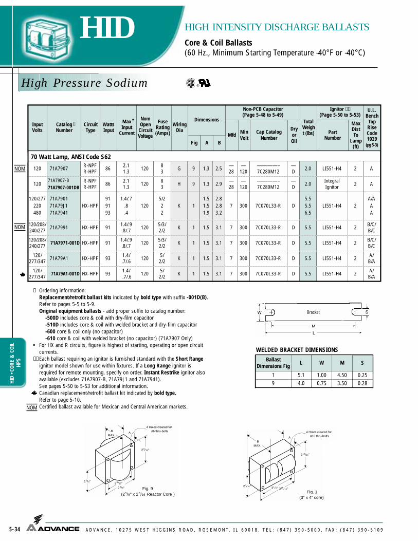
Cap CatalogNumber
DryorOil
High Pressure Sodium
5-34
HIDHI
D • C
ORE
&CO
ILHP
S
HIGH INTENSITY DISCHARGE BALLASTSCore & Coil Ballasts(60 Hz., Minimum Starting Temperature –40°F or –40°C)
A D V A N C E , 1 0 2 7 5 W E S T H I G G I N S R O A D , R O S E M O N T, I L 6 0 0 1 8 . T E L : ( 8 4 7 ) 3 9 0 - 5 0 0 0 , F A X : ( 8 4 7 ) 3 9 0 - 5 1 0 9
InputVolts
CatalogNumber
CircuitType
WattsInput
MaxInput
Current
NomOpen
CircuitVoltage
FuseRating(Amps)
Fig
Dimensions
Non-PCB Capacitor(Page 5-48 to 5-49)
Mfd MinVolt
TotalWeight (Ibs)
Ignitor ✝✝(Page 5-50 to 5-53)
PartNumber
MaxDistTo
Lamp(ft)
U.L.Bench
TopRiseCode1029(pg 5-3)A B
✝•
WiringDia
WELDED BRACKET DIMENSIONS
✝ Ordering information: Replacement/retrofit ballast kits indicated by bold type with suffix -001D(B).Refer to pages 5-5 to 5-9.Original equipment ballasts - add proper suffix to catalog number:
-500D includes core & coil with dry-film capacitor-510D includes core & coil with welded bracket and dry-film capacitor-600 core & coil only (no capacitor)-610 core & coil with welded bracket (no capacitor) (71A7907 Only)
• For HX and R circuits, figure is highest of starting, operating or open circuitcurrents.
✝✝ Each ballast requiring an ignitor is furnished standard with the Short Rangeignitor model shown for use within fixtures. If a Long Range ignitor isrequired for remote mounting, specify on order. Instant Restrike ignitor alsoavailable (excludes 71A7907-B, 71A79J1 and 71A7941). See pages 5-50 to 5-53 for additional information.Canadian replacement/retrofit ballast kit indicated by bold type.Refer to page 5-10.Certified ballast available for Mexican and Central American markets.
23/16"
23/16"
25/8"
13/4"
BMAX.
A
Fig. 9(25/8" x 2 3/16 Reactor Core )
4 Holes cleared for#6 thru-bolts
213 /16 "
31/2" 315/16"27/16"
BMAX.
A
Fig. 1(3" x 4" core)
4 Holes cleared for#10 thru-bolts
BallastDimensions Fig L W M S
1 5.1 1.00 4.50 0.259 4.0 0.75 3.50 0.28
70 Watt Lamp, ANSI Code S62
120 71A7907 R-NPFR-HPF 86 2.1
1.3 120 83 9 1.3 2.5 —
28—
120————– 7C280M12
—D 2.0 LI551-H4 2 A
12071A7907-B71A7907-001DB
R-NPFR-HPF 86 2.1
1.3 120 83 9 1.3 2.9 —
28—
120————– 7C280M12
—D 2.0 Integral
Ignitor 2 A
120/277220480
71A790171A79J171A7941
HX-HPF919193
1.4/.7.8.4
1205/222
11.51.51.9
2.82.83.2
7 300 7C070L33-R D5.55.56.5
LI551-H4 2A/AAA
120/208/240/277 71A7991 HX-HPF 91 1.4/.9
.8/.7 120 5/3/2/2 1 1.5 3.1 7 300 7C070L33-R D 5.5 B/C/
B/C
120/277/347 71A79A1 HX-HPF 93 1.4/
.7/.6 120 5/2/2 1 1.5 3.1 7 300 7C070L33-R D 5.5 A/
B/ALI551-H4
LI551-H4
2
2
LI551-H4 2120/208/240/277 71A7971-001D HX-HPF 91 1.4/.9
.8/.7 120 5/3/2/2 1 1.5 3.1 7 300 7C070L33-R D 5.5 B/C/
B/C
LI551-H4 2120/277/347 71A79A1-001D HX-HPF 93 1.4/
.7/.6 120 5/2/2 1 1.5 3.1 7 300 7C070L33-R D 5.5 A/
B/A
K
G
K
H
K
K
K
NOM
NOM
NOM

Cap CatalogNumber
DryorOil
High Pressure Sodium
5-35
HIDHID • CORE
&COIL
HPSHIGH INTENSITY DISCHARGE BALLASTSCore & Coil Ballasts(60 Hz., Minimum Starting Temperature –40°F or –40°C)
A D V A N C E , 1 0 2 7 5 W E S T H I G G I N S R O A D , R O S E M O N T, I L 6 0 0 1 8 . T E L : ( 8 4 7 ) 3 9 0 - 5 0 0 0 , F A X : ( 8 4 7 ) 3 9 0 - 5 1 0 9
InputVolts
CatalogNumber
CircuitType
WattsInput
MaxInput
Current
NomOpen
CircuitVoltage
FuseRating(Amps)
Fig
Dimensions
Non-PCB Capacitor(Page 5-48 to 5-49)
Mfd MinVolt
TotalWt.(Ibs)
Ignitor ✝✝(Page 5-50 to 5-53)
PartNumber
MaxDistTo
Lamp(ft)
U.L.Bench
TopRiseCode1029(pg 5-3)A B
✝•
WiringDia
LI551-J4 5127/220120/277
71A79H871A7988
CWA 95.8/.5.9/.4
105 2/23/1 1 1.5 2.8 28 170 7C280P30-R D 5.5
A/DA/D
120/208/240 71A79E6 CWI 95 .9/
.5/.5 110 3/2/2 1 1.6 2.9 24 300 7C240P30 D 5.8 LI551-J4 2 C/
C/D
120/240 71A7950 RegulatedLag 103 .9/.5 125 2.5/1 1 2.1 3.3 20 300 7C200P33-R D 6.3 LI551-H4 2 D/B
M
V
N
70 Watt Lamp, ANSI Code S62
✝ Ordering information: Original equipment ballasts - add proper suffix to catalog number:
-500D includes core & coil with dry-film capacitor-510D includes core & coil with welded bracket and dry-film capacitor-600 core & coil only (no capacitor)-610 core & coil with welded bracket (no capacitor)
• For CWA, CWI and Regulated Lag circuits, figure is operating current. ✝✝ Each ballast requiring an ignitor is furnished standard with the Short Range
ignitor model shown for use within fixtures. If a Long Range ignitor isrequired for remote mounting, specify on order. See pages 5-50 to 5-53 foradditional information.Certified ballast available for Mexican and Central American markets.
Fig. M
LAMP
CAP
LAMP
COM COM
LINE V
LINE V
LINE V
IGNITOR
X1X3
X2
LINE V
CAP CAP
Fig. N
LAMP 1
CAP
LAMP
COM
LINE V
LINE V
LINE V
IGNITORX1X3
X2
LINE V
CAP
CAP
LAMP 2
Fig. V
LAMP 1
CAP
LAMP
COM
LINE V
LINE V
LINE V
IGNITOR
X1X3
X2
LAMP 2CAP
Fig. G
COM
LAMP
CAP(OPTIONAL)
IGNITOR
LAMP
X3X1
X2
LINE V
Fig. H
COM
LAMP
CAPIGNITOR
LAMP
LINE V
INTEGRATEDIGNITOR BALLAST
Fig. K
LAMP
CAP LAMP
COM COM
LINE V
LINE V
COMLINE V
CAP
LINE V
IGNITOR
X1X3
X2
INTEGRALIGNITOR BALLAST
NOM
NOM

Cap CatalogNumber
DryorOil
High Pressure Sodium
5-36
HIDHI
D • C
ORE
&CO
ILHP
S
HIGH INTENSITY DISCHARGE BALLASTSCore & Coil Ballasts(60 Hz., Minimum Starting Temperature –40°F or –40°C)
A D V A N C E , 1 0 2 7 5 W E S T H I G G I N S R O A D , R O S E M O N T, I L 6 0 0 1 8 . T E L : ( 8 4 7 ) 3 9 0 - 5 0 0 0 , F A X : ( 8 4 7 ) 3 9 0 - 5 1 0 9
✝ Ordering information: Replacement/retrofit ballast kits indicated by bold type with suffix -001D(B). Refer to pages 5-5 to 5-9.Original equipment ballasts - add proper suffix to catalog number:
-500D includes core & coil with dry-film capacitor-510D includes core & coil with welded bracket and dry-film
capacitor-600 core & coil only (no capacitor)-610 core & coil with welded bracket (no capacitor) (71A8007 Only)
• For AR, HX, R and Hybrid circuits, figure is highest of starting, operating or open circuit currents.
✝✝ Each ballast requiring an ignitor is furnished standard with the Short Range ignitor model shown for use within fixtures. If a LongRange ignitor is required for remote mounting, specify on order.Instant Restrike ignitor also available (excludes 71A8005, 71A8007-B,71A80J1 and 71A8041). See pages 5-50 to 5-53 for additional information.
•• 277V operation requires the 120V reactor ballast and controller plus the 120/277V auto-transformer listed. Ballast dimensions shown in table are for the reactor ballast component only. See page 5-54 for auto-transformer specifications and dimensions.Canadian replacement/retrofit ballast kit indicated by bold type.Refer to page 5-10.
Fig. G
COM
LAMP
CAP(OPTIONAL)
IGNITOR
LAMP
X3X1
X2
LINE V
Fig. H
COM
LAMP
CAPIGNITOR
LAMP
LINE V
INTEGRATEDIGNITOR BALLAST
Fig. K
LAMP
CAP LAMP
COM COM
LINE V
LINE V
COMLINE V
CAP
LINE V
IGNITOR
X1X3
X2
INTEGRALIGNITOR BALLAST
111/16"31/16"
43/16"
p. 80 oCrounded.
RectangularCase
White SONController
InputVolts
CatalogNumber
CircuitType
WattsInput
MaxInput
Current
NomOpen
CircuitVoltage
FuseRating(Amps)
Fig
Dimensions
Non-PCB Capacitor(Page 5-48 to 5-49)
Mfd MinVolt
TotalWt.(Ibs)
Ignitor ✝✝(Page 5-50 to 5-53)
PartNumber
MaxDistTo
Lamp(ft)
U.L.Bench
TopRiseCode1029(pg 5-3)A B
✝•
WiringDia
100 Watt Lamp, ANSI Code S105, (White SON-Philips) (Minimum Starting Temperature –20°F or –30°C)
120 71A8005 HybridElectronic 120 2.2 120 5 9 2.0 3.2 45 120 7C450P12 D 5.5 6C100
Controller 2 A
120/277••
71A8005(120V)
+71A9876(120/277V
Auto transformer)
HybridElectronic
AR125 1.0 120 5/3 9
(2pcs)2.0 3.2 45 120 7C450P12 D 9.5 6C100
Controller 2 A/A
100 Watt Lamp, ANSI Code S54
120 71A8007R-NPFR-HPF
1153.11.8
120105
9 1.5 2.7—36
—120
————–7C360M12
— D
2.52.8
LI551-H4 2 A
120/277220
71A800171A80J1
HX-HPF 1302.2/.9
1.2120
7/33
1 2.0 3.3 10 280 7C100M33-R D 7.2 LI551-H4 2C/CB
120/208/240/277 71A8091 HX-HPF 130 2.2/1.3/
1.1/.9 120 7/5/3/3 1 2.0 3.6 10 280 7C100M33-R D 7.2 LI551-H4 2 D/F/
D/D
120/208/240/277 71A8071-001D HX-HPF 130 2.2/1.3/
1.1/.9 120 7/5/3/3 1 2.0 3.6 10 280 7C100M33-R D 7.2 LI551-H4 2 D/F/
D/D
120/277/347 71A80A1 HX-HPF 130 2.2/
.9/.7 120 7/3/3 1 2.3 3.6 10 280 7C100M33-R D 7.5 LI551-H4 2 C/
C/D
48071A804171A8041-001D
HX-HPF 130 .6 120 3 1 2.3 3.6 10 280 7C100M33-R D 7.5 LI551-H4 2 EK
R
S
G
K
K
K
K
120/277/347 71A80A1-001D HX-HPF 130 2.2/
.9/.7 120 7/3/3 1 2.3 3.6 10 280 7C100M33-R D 7.5 LI551-H4 2 C/
C/DK
12071A8007-B71A8007-001DB
R-NPFR-HPF
1153.11.8
120105
9 1.5 2.7—36
—120
————–7C360M12
—D
2.52.8
IntegralIgnitor
2 A/AH

InputVolts
CatalogNumber†
CircuitType
WattsInput
Max•
InputCurrent
NomOpenCircuitVoltage
FuseRating(Amps)
WiringDia
Dimensions Non-PCB Capacitor(Page 5-48 to 5-49)
TotalWeight(lbs)
Ignitor††
(Page 5-50 to 5-53)U.L.
BenchTopRiseCode1029
(pg 5-3)
Fig A B Mfd MinVolt
Cap CatalogNumber
DryorOil
PartNumber
MaxDistTo
Lamp(ft)
100 Watt Lamp, ANSI Code S54120/277127/220480/120T
71A808871A80H871A8048-T
CWA 1381.2/.51.1/.7
.3115
3/23/21
M 1 2.0 3.3 34 170 7C340P24 D 7.5 LI551-J4 5F/FE/DE
120/208/240 71A80EG CWI 130 1.2/
.7/.6 110 3/2/2 V 1 2.1 3.4 35 170 7C350P24 D 6.8 LI551-J4 2 C/
C/B
120/240120/277240/480
71A805071A808071A8060
RegulatedLag 138
1.2/.61.2/.6.6/.3
1203/23/2
1.5/1N 2 1.4 3.0 16 330 7C160M33 D 8.5 LI551-H4 2
A/AA/AA/A
120/240 71A8056 CWI 130 1.3/0.7 108 3/2 V 1 2.1 3.4 35 170 7C350P24 D 6.8 LI551-J4 2 C/B230 71A80J8 CWA 136 0.7 118 2 M 1 2.0 3.3 34 170 7C350P24 D 7.5 LI551-J4 5 E
220/240 7180J9 CWA 124 0.6/0.6 117 2/2 M 1 2.8 4.6 34 240 7C340P24 D 10.5 LI551-J4 5 A/A
High Pressure Sodium
5-37
HIDHID • CORE
&COIL
HPSHIGH INTENSITY DISCHARGE BALLASTSCore & Coil Ballasts(60 Hz., Minimum Starting Temperature –40°F or –40°C)
A D V A N C E , 1 0 2 7 5 W E S T H I G G I N S R O A D , R O S E M O N T, I L 6 0 0 1 8 . T E L : ( 8 4 7 ) 3 9 0 - 5 0 0 0 , F A X : ( 8 4 7 ) 3 9 0 - 5 1 0 9
Fig. N
LAMP 1
CAP
LAMP
COM
LINE V
LINE V
LINE V
IGNITORX1X3
X2
LINE V
CAP
CAP
LAMP 2
Fig. M
LAMP
CAP
LAMP
COM COM
LINE V
LINE V
LINE V
IGNITOR
X1X3
X2
LINE V
CAP CAP
Fig. V
LAMP 1
CAP
LAMP
COM
LINE V
LINE V
LINE V
IGNITOR
X1X3
X2
LAMP 2CAP
WELDED BRACKET DIMENSIONS
✝ Ordering information: Original equipment ballasts - add proper suffix to catalog number:
-500D includes core & coil with dry-film capacitor-510D includes core & coil with welded bracket and dry-film capacitor-600 core & coil only (no capacitor)-610 core & coil with welded bracket (no capacitor)
• For CWA, CWI and Regulated Lag circuits, figure is operating current. ✝✝ Each ballast requiring an ignitor is furnished standard with the Short Range ignitor model shown
for use within fixtures. If a Long Range ignitor is required for remote mounting, specify on order.See pages 5-50 to 5-53 for additional information.Certified ballast available for Mexican and Central American markets.
LLSpecial High Efficiency/Low Loss Magnetic ballast
213 /16 "
31/2" 315/16"27/16"
BMAX.
A
Fig. 1(3" x 4" core)
4 Holes cleared for#10 thru-bolts
LAMP (BLUE) LVLAMP
3
4
REACTOR
LAMP (RED) HV
120 V
NEUTRAL
CAP
CONTROLLER
Fig. R
LAMP (BLUE) LVLAMP
3
4
REACTOR
LAMP (RED) HV
120 V
NEUTRAL/COM
CAPCONTROLLER
Fig. S
277VAUTO TRANSFORMER
23/16"
23/16"
25/8"
3/4"
BMAX.
A
Fig. 9(25/8" x 2 3/16 Reactor Core )
4 Holes cleared for#6 thru-bolts
BallastDimensions Fig L W M S
2 6.5 1.25 5.75 0.289 4.0 0.75 3.50 0.28
1 5.1 1.00 4.50 0.25
NOM
NOM
NOM
NOM LL

Cap CatalogNumber
DryorOil
High Pressure Sodium
5-38
HIDHI
D • C
ORE
&CO
ILHP
S
HIGH INTENSITY DISCHARGE BALLASTSCore & Coil Ballasts(60 Hz., Minimum Starting Temperature –40°F or –40°C)
A D V A N C E , 1 0 2 7 5 W E S T H I G G I N S R O A D , R O S E M O N T, I L 6 0 0 1 8 . T E L : ( 8 4 7 ) 3 9 0 - 5 0 0 0 , F A X : ( 8 4 7 ) 3 9 0 - 5 1 0 9
InputVolts
CatalogNumber
CircuitType
WattsInput
MaxInput
Current
NomOpen
CircuitVoltage
FuseRating(Amps)
Fig
Dimensions
Non-PCB Capacitor(Page 5-48 to 5-49)
Mfd MinVolt
TotalWeight(Ibs)
Ignitor ✝✝(Page 5-50 to 5-53)
PartNumber
MaxDistTo
Lamp(ft)
U.L.Bench
TopRiseCode1029(pg 5-3)A B
✝•
WiringDia
Fig. G
COM
LAMP
CAP(OPTIONAL)
IGNITOR
LAMP
X3X1
X2
LINE V
Fig. H
COM
LAMP
CAPIGNITOR
LAMP
LINE V
INTEGRATEDIGNITOR BALLAST
Fig. K
LAMP
CAP LAMP
COM COM
LINE V
LINE V
COMLINE V
CAP
LINE V
IGNITOR
X1X3
X2
✝ Ordering information: Replacement/retrofit ballast kits indicated by bold type with suffix -001D(B). Refer to pages 5-5 to 5-9.Original equipment ballasts - add proper suffix to catalog number:
-500D includes core & coil with dry-film capacitor-510D includes core & coil with welded bracket and dry-film capacitor-600 core & coil only (no capacitor)-610 core & coil with welded bracket (no capacitor) (71A8107 Only)
• For HX and R circuits, figure is highest of starting, operating or open circuit currents.✝✝ Each ballast requiring an ignitor is furnished as standard with the Short Range ignitor
model shown for use within fixtures. If a Long Range ignitor is required for remotemounting, specify on order. Instant Restrike ignitor also available (excludes 71A8107-B, 71A81J2, 71A8132 and 71A8142). See pages 5-50 to 5-53 for additional information.Canadian replacement/retrofit ballast kit indicated by bold type.Refer to page 5-10.
INTEGRALIGNITOR BALLAST
150 Watt Lamp, ANSI Code S55 (55-Volt Arc Tube)
120
120
71A8107
71A8107-B71A8107-001DB
R-NPFR-HPF
R-NPFR-HPF
170
170
4.52.4
4.52.4
120
120
158
158
9
9
2.0
2.0
3.3
3.6
—55
—55
—120
—120
–––––––– 7C550P12
–––––––– 7C550P12
—D
— D
3.54.0
3.54.0
LI551-H4
IntegralIgnitor
2
2
A
A
120/277220277
71A810271A81J271A8132
HX-HPF 1882.8/1.3
1.51.3
12010/4
44
1 2.6 3.8 14 280 7C140M33-R D 7.5 LI551-H4 2E/ECD
120/208/240/277 71A8192 HX-HPF 188 2.8/1.6/
1.4/1.3 120 10/5/5/4 1 2.6 3.8 14 280 7C140M33-R D 7.5 LI551-H4 2 E/D/
E/D
120/277/347 71A81A2 HX-HPF 188 2.8/
1.3/.9 120 10/4/3 1 2.6 3.8 14 280 7C140M33-R D 7.5 LI551-H4 2 D/
D/D
120/208/240/277 71A8172-001D HX-HPF 188 2.8/1.6/
1.4/1.3 120 10/5/5/5 1 2.6 3.8 14 280 7C140M33-R D 7.5 LI551-H4 2 E/D/
E/D
480
480/120T
71A814271A8142-001D
71A8142-T
HX-HPF
HX-HPF
188
188
0.7
0.7
120
120
2
2
1
1
3.0
3.0
4.3
4.3
14
14
280
280
7C140M33-R
7C140M33-R
D
D
9.0
9.0
LI551-H4
LI551-H4
2
2
E
E
K
G
H
K
K
K
K
K
120/277/347 71A81A2-001D HX-HPF 188 2.8/
1.3/.9 120 10/4/3 1 2.6 3.8 14 280 7C140M33-R D 7.5 LI551-H4 2 D/
D/DK

Cap CatalogNumber
DryorOil
High Pressure Sodium
5-39
HIDHID • CORE
&COIL
HPSHIGH INTENSITY DISCHARGE BALLASTSCore & Coil Ballasts(60 Hz., Minimum Starting Temperature –40°F or –40°C)
A D V A N C E , 1 0 2 7 5 W E S T H I G G I N S R O A D , R O S E M O N T, I L 6 0 0 1 8 . T E L : ( 8 4 7 ) 3 9 0 - 5 0 0 0 , F A X : ( 8 4 7 ) 3 9 0 - 5 1 0 9
InputVolts
CatalogNumber
CircuitType
WattsInput
MaxInput
Current
NomOpen
CircuitVoltage
FuseRating(Amps)
Fig
Dimensions
Non-PCB Capacitor(Page 5-48 to 5-49)
Mfd MinVolt
TotalWeight(Ibs)
Ignitor ✝✝(Page 5-50 to 5-53)
PartNumber
MaxDistTo
Lamp(ft)
U.L.Bench
TopRiseCode1029(pg 5-3)A B
✝•
WiringDia
41/4"
43/8" 43/4"37/8"
BMAX.
A
Fig. 2(41/4" x 4 3/4" core)
4 Holes cleared for#10 thru-bolts
Fig. M
LAMP
CAP
LAMP
COM COM
LINE V
LINE V
LINE V
IGNITOR
X1X3
X2
LINE V
CAP CAP
✝ Ordering information: Replacement/retrofit ballast kits indicated by bold type with suffix -001D. Refer to pages 5-5 to 5-9.Original equipment ballasts - add proper suffix to catalog number:
-500D includes core & coil with dry-film capacitor-510D includes core & coil with welded bracket and dry-film capacitor-600 core & coil only (no capacitor)-610 core & coil with welded bracket (no capacitor)
• For CWA, CWI and Regulated Lag circuits, figure is operating current.✝✝ Each ballast requiring an ignitor is furnished as standard with the Short Range ignitor model shown
for use within fixtures. If a Long Range ignitor is required for remote mounting, specify on order. Seepages 5-50 to 5-53 for additional information.Certified ballast available for Mexican and Central American markets.
LLSpecial High Efficiency/Low Loss Magnetic ballast
WELDED BRACKET DIMENSIONSFig. N
LAMP 1
CAP
LAMP
COM
LINE V
LINE V
LINE V
IGNITORX1X3
X2
LINE V
CAP
CAP
LAMP 2
Fig. V
LAMP 1
CAP
LAMP
COM
LINE V
LINE V
LINE V
IGNITOR
X1X3
X2
LAMP 2CAP
213 /16 "
31/2" 315/16"27/16"
BMAX.
A
Fig. 1(3" x 4" core)
4 Holes cleared for#10 thru-bolts
BallastDimensions Fig L W M S
1 5.1 1.00 4.50 0.252 6.5 1.25 5.75 0.289 4.0 0.75 3.50 0.28
120/277127/220
480
71A818871A81H871A8148
CWA 1901.7/.71.6/.9
.5110
5/34/21
12.82.82.5
4.14.13.8
55 170 7C550P24 D8.58.58.0
LI551-J4 10
120/208/240 71A81E6 CWI 190 1.7/
1.1/.8 105 5/3/3 1 2.6 4.0 52 240 7C520P24 D 8.5 LI551-J4 2
120/240120/277240/480
71A815071A818071A8160
RegulatedLag 196
1.7/.91.7/.8.9/.4
1205/35/23/1
2 2.0 3.5 16 400 7C160P40 D 12.0 LI551-H4 2
M
V
N
150 Watt Lamp, ANSI Code S55 (55-Volt Arc Tube)
150 Watt Lamp, ANSI Code S56 (100-Volt Arc Tube)
120/208/240/277 71A8196 CWA 188 1.7/1.0
.9/.8 180 5/3/3/3 1 2.5 4.1 20 280 7C200P33-R D 8.5 E/D/
C/CLI501-H4 2
LI501-H4 2120/208/240/277 71A8176-001D CWA 188 1.7/1.0
.9/.8 180 5/3/3/3 1 2.5 4.1 20 280 7C200P33-R D 8.5 E/D/
C/C
LI501-H4 2480 71A8146-001D CWA 188 0.5 180 2 1 2.5 3.8 20 280 7C200P33-R D 8.5 B
M
M
LI551-J4 2220/240 71A81J9 CWA 170 0.8/0.7 111 2/2 2 2.5 3.8 60 240 7C600P24 D 13.5 A/AM
M
E/E/D
B/BB/AB/B
E/DD/CE
23/16"
23/16"
25/8"
13/4"
BMAX.
A
Fig. 9(25/8" x 2 3/16 Reactor Core )
4 Holes cleared for#6 thru-bolts
NOM
NOM
LL

High Pressure Sodium
5-40
HIDHI
D • C
ORE
&CO
ILHP
S
HIGH INTENSITY DISCHARGE BALLASTSCore & Coil Ballasts(60 Hz., Minimum Starting Temperature –40°F or –40°C)
A D V A N C E , 1 0 2 7 5 W E S T H I G G I N S R O A D , R O S E M O N T, I L 6 0 0 1 8 . T E L : ( 8 4 7 ) 3 9 0 - 5 0 0 0 , F A X : ( 8 4 7 ) 3 9 0 - 5 1 0 9
✝ Ordering information: Replacement/retrofit ballast kits indicated by bold type with suffix -001D.Refer to pages 5-5 to 5-9.Original equipment ballasts - add proper suffix to catalog number:
-500D includes core & coil with dry-film capacitor-510D includes core & coil with welded bracket and dry-film capacitor-600 core & coil only (no capacitor)-610 core & coil with welded bracket (no capacitor)
• For CWA and Regulated Lag circuits, figure is operating current.✝✝ Each ballast requiring an ignitor is furnished as standard with the Short Range ignitor model shown for
use within fixtures. If a Long Range ignitor is required for remote mounting, specify on order. Seepages 5-50 to 5-53 for additional information.
◆ Special compact 3 x 4 core design. Note Bench Top Rise Codes in last column.41/4"
43/8" 43/4"37/8"
BMAX.
A
Fig. 2(41/4" x 4 3/4" core)
4 Holes cleared for#10 thru-bolts
Fig. M
LAMP
CAP
LAMP
COM COM
LINE V
LINE V
LINE V
IGNITOR
X1X3
X2
LINE V
CAP CAP
Fig. N
LAMP 1
CAP
LAMP
COM
LINE V
LINE V
LINE V
IGNITORX1X3
X2
LINE V
CAP
CAP
LAMP 2
213 /16 "
31/2" 315/16"27/16"
BMAX.
A
Fig. 1(3" x 4" core)
4 Holes cleared for#10 thru-bolts
WELDED BRACKET DIMENSIONS
BallastDimensions Fig L W M S
1 5.1 1.00 4.50 0.252 6.5 1.25 5.75 0.283 7.8 2.75 6.13 0.25
Fig. V
LAMP 1
CAP
LAMP
COM
LINE V
LINE V
LINE V
IGNITOR
X1X3
X2
LAMP 2CAP
InputVolts
CatalogNumber†
CircuitType
WattsInput
Max•
InputCurrent
NomOpenCircuitVoltage
FuseRating(Amps)
WiringDia
Dimensions Non-PCB Capacitor(Page 5-48 to 5-49)
TotalWeight(lbs)
Ignitor††
(Page 5-50 to 5-53) U.L.Bench
TopRiseCode1029
(pg 5-3)
Fig A B Mfd MinVolt
Cap CatalogNumber
DryorOil
PartNumber
MaxDistTo
Lamp(ft)
200 Watt Lamp, ANSI Code S66
48071A894071A8940-001D
CWA 240 .6 185 2 M 2 1.2 3.0 28 280 7C280P30-R D 8.5 LI501-H4 2 C
120/208/240/277 71A8990 CWA 240 2.2/1.3
1.1/1.0 185 6/4/3/3 M 2 1.2 3.0 28 280 7C280P30-R D 8.5 LI501-H4 2 E/D/
D/C
120/208/240/277 71A8970-001D CWA 240 2.2/1.3
1.1/1.0 185 6/4/3/3 M 2 1.2 3.0 28 280 7C280P30-R D 8.5 LI501-H4 2 E/D/
D/C
480 71A8941 CWA 250 .6 195 2 M 1 3.0 4.2 24 280 7C240P30 D 8.5 LI501-H4 2 J
120/208/240/277 71A8991 CWA 250 2.4/1.4
1.2/1.0 195 8/5/5/3 M 1 3.0 4.2 24 280 7C240P30 D 8.5 LI501-H4 2 H/G/
H/I
120/240 71A8954 RegulatedLag 255 2.2/1/1 225 6/3 N 2 2.3 3.9 18 400 7C180P40-R D 14.0 LI501-H4 2 C
240/480 71A8964 RegulatedLag 255 1.1/.7 225 3/2 N 2 2.3 3.9 18 400 7C180P40-R D 14.0 LI501-H4 2 C
120/208/240/277/
48071A8950 CWA 242
2.1/1.21.1/1.0
0.6199 6/5/
3/3/2 M 2 1.4 3.0 28 280 7C280P30-R D 9.0 LI501-H4 2 C/B/B/B/B

Cap CatalogNumber
DryorOil
B/B/B/B/
B
120/208/240/277/
480
71A825171A8251-001D
CWA 3002.6/1.5/1.3/1.2/
.7185
10/4/4/3/
22 2.0 3.6 35 240 7C350P24 D 12.0 LI501-H4 2M
High Pressure Sodium
5-41
HIDHID • CORE
&COIL
HPSHIGH INTENSITY DISCHARGE BALLASTSCore & Coil Ballasts(60 Hz., Minimum Starting Temperature –40°F or –40°C)
A D V A N C E , 1 0 2 7 5 W E S T H I G G I N S R O A D , R O S E M O N T, I L 6 0 0 1 8 . T E L : ( 8 4 7 ) 3 9 0 - 5 0 0 0 , F A X : ( 8 4 7 ) 3 9 0 - 5 1 0 9
✝ Ordering information: Replacement/retrofit ballast kits indicated by bold type with suffix -001D.Refer to pages 5-5 to 5-9.Original equipment ballasts - add proper suffix to catalog number:
-500D includes core & coil with dry-film capacitor-510D includes core & coil with welded bracket and dry-film capacitor-600 core & coil only (no capacitor)-610 core & coil with welded bracket (no capacitor)
• For CWA circuits, figure is operating current. ✝✝ Each ballast requiring an ignitor is furnished as standard with the Short
Range ignitor model shown for use within fixtures. If a Long Range ignitoris required for remote mounting, specify on order. See pages 5-50 to 5-53for additional information.Canadian replacement/retrofit ballast kit indicated by bold type.Refer to page 5-10.pages 5-50 to 5-53 for additional information.Certified ballast available for Mexican and Central American markets.
LLSpecial High Efficiency/Low Loss Magnetic ballast
InputVolts
CatalogNumber
CircuitType
WattsInput
MaxInput
Current
NomOpen
CircuitVoltage
FuseRating(Amps)
Fig
Dimensions
Non-PCB Capacitor(Page 5-48 to 5-49)
Mfd MinVolt
TotalWeight(Ibs)
Ignitor ✝✝(Page 5-50 to 5-53)
PartNumber
MaxDistTo
Lamp(ft)
U.L.Bench
TopRiseCode1029(pg 5-3)A B
✝•
WiringDia
120/277
AD/CB
250 Watt Lamp, ANSI Code S50120
127/220277
71A820171A82H171A8231
CWA 2952.5
2.5/1.51.1
1857
7/43
2 1.8 3.5 35 240 7C350P24 D 11.0 LI501-H4 2
71A8281 CWA 295 2.5/1.1 185 7/3 2 1.8 3.5 35 240 7C350P24 D 11.0 LI501-H4 2 B/B
120/208/240/277 71A8291 CWA 295 2.5/1.5/
1.3/1.1 185 7/4/4/3 2 1.8 3.5 35 240 7C350P24 D 11.0 LI501-H4 2 B/A/
B/B
120/277/347 71A82A1 CWA 295 2.7/
1.2/.9 185 7/3/2 2 2.0 3.6 35 240 7C350P24 D 11.5 LI501-H4 2 C/
C/B
120/208/240/277 71A8271-001D CWA 295 2.5/1.5/
1.3/1.1 185 7/4/4/3 2 1.8 3.5 35 240 7C350P24 D 11.0 LI501-H4 2 B/A/
B/B
480
480/120T
71A824171A8241-001D
71A8241-T
CWA
CWA
310
310
.7
.7
185
185
2
2
2
2
1.8
1.8
3.5
3.5
35
35
240
240
7C350P24
7C350P24
D
D
11.0
11.0
LI501-H4
LI501-H4
2
2
B
B
M
M
M
M
M
M
220/240 71A82J9 CWA 285 1.4/1.3 188 4/4 2 1.8 3.4 34 240 7C340P24 D 11.0 LI501-H4 5 A/AM
120/208/240/277 71A8296 CWI 300 2.6/1.5/
1.3/1.2 190 7/5/3/3 2 1.9 3.5 28 300 7C280P30R D 11.0 LI501J4 5 E/C/
C/CV
M
120/277/347 71A82A1-001D CWA 295 2.7/
1.2/.9 185 7/3/2 2 2.0 3.6 35 240 7C350P24 D 11.5 LI501-H4 2 C/
C/BM
240/480 71A8260 RegulatedLag 310 1.4/.7 220 4/2 3 2.4 4.0 16 480 MD1606-000 O 18.0 LI501-H4 2 C/C
120/277 71A8280 RegulatedLag 310 2.7/1.2 220 8/3 3 2.4 4.0 16 480 MD1606-000 O 18.0 LI501-H4 2 C/C
120/208/240 71A82E6 CWI 300 2.8/
1.6/1.4 190 8/5/5 2 1.9 3.8 28 300 7C280P30-R D 11.0 LI501-J4 2 D/
C/CV
N
N
120/240 71A8250 RegulatedLag 310 2.7/1.4 220 8/4 3 2.4 4.0 16 480 MD1606-000 O 18.0 LI501-H4 2 C/CN
NOM
NOM
LL
NOM

High Pressure Sodium
5-42
HIDHI
D • C
ORE
&CO
ILHP
S
HIGH INTENSITY DISCHARGE BALLASTSCore & Coil Ballasts(60 Hz., Minimum Starting Temperature –40°F or –40°C)
A D V A N C E , 1 0 2 7 5 W E S T H I G G I N S R O A D , R O S E M O N T, I L 6 0 0 1 8 . T E L : ( 8 4 7 ) 3 9 0 - 5 0 0 0 , F A X : ( 8 4 7 ) 3 9 0 - 5 1 0 9
✝ Ordering information: Replacement/retrofit ballast kits indicated by bold type with suffix -001D.Refer to pages 5-5 to 5-9.Original equipment ballasts - add proper suffix to catalog number:
-500D includes core & coil with dry-film capacitor-510D includes core & coil with welded bracket and dry-film capacitor-500 includes core & coil with oil-filled capacitor-510 includes core & coil with welded bracket and oil-filled capacitor-600 core & coil only (no capacitor)-610 core & coil with welded bracket (no capacitor)
• For CWA and Regulated Lag circuits, figure is operating current.✝✝ Each ballast requiring an ignitor is furnished as standard with the Short Range ignitor model
shown for use within fixtures. If a Long Range ignitor is required for remote mounting,specify on order. See pages 5-50 to 5-53 for additional information.
Fig. M
LAMP
CAP
LAMP
COM COM
LINE V
LINE V
LINE V
IGNITOR
X1X3
X2
LINE V
CAP CAP
WELDED BRACKET DIMENSIONS
41/4"
43/8" 43/4"37/8"
BMAX.
A
Fig. 2(41/4" x 4 3/4" core)
4 Holes cleared for#10 thru-bolts
Fig. N
LAMP 1
CAP
LAMP
COM
LINE V
LINE V
LINE V
IGNITORX1X3
X2
LINE V
CAP
CAP
LAMP 2
Fig. V
LAMP 1
CAP
LAMP
COM
LINE V
LINE V
LINE V
IGNITOR
X1X3
X2
LAMP 2CAP
BallastDimensions Fig L W M S
2 6.5 1.25 5.75 0.283 7.8 2.75 6.13 0.25
InputVolts
CatalogNumber†
CircuitType
WattsInput
Max•
InputCurrent
NomOpenCircuitVoltage
FuseRating(Amps)
WiringDia
Dimensions Non-PCB Capacitor(Page 5-48 to 5-49)
TotalWeight(lbs)
Ignitor††
(Page 5-50 to 5-53)U.L.
BenchTopRiseCode1029
(pg 5-3)
Fig A B Mfd MinVolt
Cap CatalogNumber
DryorOil
PartNumber
MaxDistTo
Lamp(ft)
310 Watt Lamp, ANSI Code S67480 71A8341 CWA 365 0.9 175 3 M 2 2.2 3.8 45 280 7C450P30-R D 13.5 LI501-H4 2 D
120/208/240/277 71A8391 CWI 365 3.4/1.9/
1.7/1.4 175 8/5/5/5 M 2 2.2 4.1 45 280 7C450P30-R D 13.5 LI501-H4 2 D/D/
D/B120/208/240/277 71A8371-001D CWA 365 3.4/1.9/
1.7/1.4 175 8/5/5/5 M 2 2.2 4.1 45 280 7C450P30-R D 13.5 LI501-H4 2 D/C/
D/B
120/240240/480
71A835071A8360
RegulatedLag 380 3.3/1.7
1.7/.9 210 9/44/3 N 3 2.8 4.5 17 525 MD1701-000 D 21.0 LI501-H4 2 C/B
C/B
120/208/240/277/
48071A8351 CWA 367 3.2/1.7/1
.6/1.4/.8 183 8/5/4/4/2 M 2 2.5 4.1 45 280 7C450P30-R D 14.0 LI501-H4 2 C/A/B/
B/B

Cap CatalogNumber
DryorOil
120/208/240/277/
480
71A845371A8453-001D
CWA 4653.9/2.2/1.9/1.7/
1.0195
10/6/5/5/
32 2.7 4.4 55 240 7C550P24 D 16.0 LI501-H4 2
C/C/D/D/
CM
High Pressure Sodium
5-43
HIDHID • CORE
&COIL
HPSHIGH INTENSITY DISCHARGE BALLASTSCore & Coil Ballasts(60 Hz., Minimum Starting Temperature –40°F or –40°C)
A D V A N C E , 1 0 2 7 5 W E S T H I G G I N S R O A D , R O S E M O N T, I L 6 0 0 1 8 . T E L : ( 8 4 7 ) 3 9 0 - 5 0 0 0 , F A X : ( 8 4 7 ) 3 9 0 - 5 1 0 9
✝ Ordering information: Replacement/retrofit ballast kits indicated by bold type with suffix -001D.Refer to pages 5-5 to 5-9.Original equipment ballasts - add proper suffix to catalog number:
-500D includes core & coil with dry-film capacitor-510D includes core & coil with welded bracket and dry-film capacitor-500 includes core & coil with oil-filled capacitor-510 includes core & coil with welded bracket and oil-filled capacitor-600 core & coil only (no capacitor)-610 core & coil with welded bracket (no capacitor)
• For CWA, CWI and Regulated Lag circuits, figure is operating current.✝✝ Each ballast requiring an ignitor is furnished as standard with the Short
Range ignitor model shown for use within fixtures. If a Long Range ignitoris required for remote mounting, specify on order. See pages 5-50 to 5-53for additional information.Certified ballast available for Mexican and Central American markets.
DD/CD
D
D/D/D/D
D/D/D
D/D/D/D
D
D/D/D
InputVolts
CatalogNumber
CircuitType
WattsInput
MaxInput
Current
NomOpen
CircuitVoltage
FuseRating(Amps)
Fig
Dimensions
Non-PCB Capacitor(Page 5-48 to 5-49)
Mfd MinVolt
TotalWeight(Ibs)
Ignitor ✝✝(Page 5-50 to 5-53)
PartNumber
MaxDistTo
Lamp(ft)
U.L.Bench
TopRiseCode1029(pg 5-3)A B
✝•
WiringDia
120/208/240 71A84E6 CWI 465 4.2/
2.4/2.1 190 10/7/5 2 2.7 4.4 48 300 7C480P30 D 15.5 LI501-J4 2 E/
E/E
480/120T120/240120/277240/480
71A8440-T71A845071A848071A8460
RegulatedLag
490
1.14.2/2.14.2/1.82.1/1.1
215
510/510/55/5
3 3.6 5.3 24 480 MD2409-000 O 26.0 LI501-H4 2
CD/CD/CD/B
V
N
400 Watt Lamp, ANSI Code S51120
127/220277
71A840371A84H371A8433
CWA 4573.8
3.7/2.11.7
1901055
2 2.3 4.0 55 240 7C550P24 D 13.5 LI501-H4 2
480/120T 71A8443-T CWA 464 1.0 190 3 2 2.6 4.3 55 240 7C550P24 D 15.0 LI501-H4 2
120/208/240/277 71A8493 CWA 464 3.8/2.2/
1.9/1.7 190 10/8/5/5 2 2.3 4.0 55 240 7C550P24 D 13.5 LI501-H4 2
120/277/347 71A84A3 CWA 464 3.8/
1.7/1.3 190 10/5/5 2 2.3 4.0 55 240 7C550P24 D 13.5 LI501-H4 2
120/208/240/277 71A8473-001D CWA 464 3.8/2.2/
1.9/1.7 190 10/8/5/5 2 2.3 4.0 55 240 7C550P24 D 13.5 LI501-H4 2
48071A844371A8443-001D
CWA 464 1.0 190 3 2 2.6 4.3 55 240 7C550P24 D 15.0 LI501-H4 2
M
M
M
E/E120/240 71A8456 CWI 465 4.2/2.1 190 10/5 2 2.7 4.4 48 300 7C480P30 D 15.5 LI501-J4 2M
M
M
M
M120/277/347 71A84A3-001D CWA 464 3.8/
1.7/1.3 190 10/5/5 2 2.3 4.0 55 240 7C550P24 D 13.5 LI501-H4 2
NOM
NOM
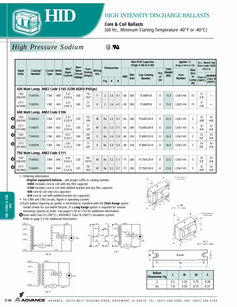
Cap CatalogNumber
DryorOil
75 7C750S28-R280
A/A/A
A/A/A
A/A/A
A/A/A
—
—
A/A/A
A/A/A
High Pressure Sodium
5-44
HIDHI
D • C
ORE
&CO
ILHP
S
HIGH INTENSITY DISCHARGE BALLASTSCore & Coil Ballasts(60 Hz., Minimum Starting Temperature –40°F or –40°C)
A D V A N C E , 1 0 2 7 5 W E S T H I G G I N S R O A D , R O S E M O N T, I L 6 0 0 1 8 . T E L : ( 8 4 7 ) 3 9 0 - 5 0 0 0 , F A X : ( 8 4 7 ) 3 9 0 - 5 1 0 9
Fig. M
LAMP
CAP
LAMP
COM COM
LINE V
LINE V
LINE V
IGNITOR
X1X3
X2
LINE V
CAP CAP
✝ Ordering information: Original equipment ballasts - add proper suffix to catalog number:-500D includes core & coil with dry-film capacitor-510D includes core & coil with welded bracket and dry-film capacitor-600 core & coil only (no capacitor)-610 core & coil with welded bracket (no capacitor)
• For CWA and CWI circuits, figure is operating current.✝✝ Each ballast requiring an ignitor is furnished as standard with the Short Range ignitor
model shown for use within fixtures. If a Long Range ignitor is required for remotemounting, specify on order. See pages 5-50 to 5-53 for additional information.Dual rated Class H (180°C) / ADVANCE Class N (200°C) insulation system.Refer to page 5-3 for additional information.
WELDED BRACKET DIMENSIONS
41/4"43/8"
6 "
37/8"
BMAX.
A
Fig. 8(41/4" x 6" core)
8 Holes cleared for#10 thru-bolts
53/8"
41/4"
43/8" 43/4"37/8"
BMAX.
A
Fig. 2(41/4" x 4 3/4" core)
4 Holes cleared for#10 thru-bolts
Fig. V
LAMP 1
CAP
LAMP
COM
LINE V
LINE V
LINE V
IGNITOR
X1X3
X2
LAMP 2CAP
8a
Fig. Y
LAMP 1
CAP
LAMP
208 V
IGNITOR
X1X3
X2
LAMP 2CAP
H4
H3
H2
H1
240 V
208 V
H4
H3
H2
H1
208V
208 V
H4
H3
H2
H1
120 V
277/347/480
600 Watt Lamp, ANSI Code S106120/
208/240 71A85E5 CWA 670 5.5/3.3/2.9 220 15/
9/8 8a 3.2 5.1 D 22.5 LI561-H5 2 A/A/B
277/347/480 71A85F5 2.5/
2.0/1.4A/
A/A
750 Watt Lamp, ANSI Code S111120/
208/240 71A86E5 CWA 840 6.8/4.0/3.5 220 20/
10/10 8a 3.2 5.1 D 22.5 LI561-H5 5 D/E/E
277/347/480 71A86F5 CWA 840 3.1/
2.5/1.8 225 10/10/5 8a 3.2 5.1 D 23.0 E/
D/D
CWA 665 230 7/5/4 8a 3.2 5.1 D 23.0 LI561-H5 5
LI561-H5 5
430 Watt Lamp, ANSI Code S145 (SON AGRO-Philips)120/
208/240C/
E/D15LI501-H415.0D48 7C480P303004.12.6215/10/72005.2/
3.0/2.6490CWI71A85E6
F/C/B15D LI501-H448 7C480P30 15.03004.12.627/
5/52002.3/1.8/1.3490CWI71A85F6
M
M
Y
V
M
M
277/347/480
120/208/240
D/D/C2LI561-H526.0D48 7C480S33-R3305.33.48a20/
9/82406.2/3.5/3.1685CWI71A85E8
D/D/C2D LI561-H548 7C480S33-R 26.03305.33.48a7/
6/52382.6/2.1/1.5685CWI71A85F8
V
V
BallastDimensions Fig L W M S
2 6.5 1.25 5.75 0.288a 7.8 4.50 6.75 0.31
N
N
N
N
N
N
N
U.L. Bench TopRise Code 1029
(Pg 5-3)
ADVANCEClass N(200°C)
Class H(180°C)
InputVolts
CatalogNumber
CircuitType
WattsInput
MaxInput
Current
NomOpen
CircuitVoltage
FuseRating(Amps)
Fig
Dimensions
Non-PCB Capacitor(Page 5-48 to 5-49)
MinVolt
TotalWeight(Ibs)
Ignitor ✝✝(Page 5-50 to 5-53)
PartNumber
MaxDistTo
Lamp(ft)
A B
✝•
WiringDia
Mfd
64 7C640S28-R280
64 7C640S28-R280
75 7C750S28-R280

Cap CatalogNumber
DryorOil
A/A/A/A
A/A/A/A
A/A/A
A
A/A/A
AAA
High Pressure Sodium
5-45
HIDHID • CORE
&COIL
HPSHIGH INTENSITY DISCHARGE BALLASTSCore & Coil Ballasts(60 Hz., Minimum Starting Temperature –40°F or –40°C)
A D V A N C E , 1 0 2 7 5 W E S T H I G G I N S R O A D , R O S E M O N T, I L 6 0 0 1 8 . T E L : ( 8 4 7 ) 3 9 0 - 5 0 0 0 , F A X : ( 8 4 7 ) 3 9 0 - 5 1 0 9
✝ Ordering information: Replacement/retrofit ballast kits indicated by bold type with suffix -001.Refer to pages 5-5 to 5-9.Original equipment ballasts - add proper suffix to catalog number:
-500 includes core & coil with oil-filled capacitor-510 includes core & coil with welded bracket and oil-filled capacitor-600 core & coil only (no capacitor)-610 core & coil with welded bracket (no capacitor)
• For CWA circuits, figure is operating current. ✝✝ Each ballast requiring an ignitor is furnished as standard with the Short
Range ignitor model shown for use within fixtures. If a Long Range ignitoris required for remote mounting, specify on order. See pages 5-50 to 5-53for additional information.
★ Equipped with an auto-reset thermal protector to prevent ignitor from over-heating in the event of lamp failure.Canadian replacement/retrofit ballast kit indicated by bold type.Refer to page 5-10.Dual rated Class H (180°C) / ADVANCE Class N (200°C) insulation system.Refer to page 5-3 for additional information.Certified ballast available for Mexican and Central American markets.
C/B/C/C
120/208/240/277 71A8793 CWA 1100 9.5/5.5/
4.8/4.2 435 25/15/10/10 8a 3.8 5.8 26 525 MD2602-030 O 28.0 C/B/
C/C
120/277/347 71A87A3 CWA 1100 9.5/
4.2/3.3 435 25/15/10 8a 3.9 5.9 26 525 MD2602-030 O 28.0 C/
C/CLI571-H5★ 15
LI571-H5★ 15
LI571-H5★ 15120/208/240/277 71A8773-001 CWA 1100 9.5/5.5/
4.8/4.2 435 25/15/10/10 8a 3.8 5.8 26 525 MD2602-030 O 28.0
48071A874371A8743-001 CWA 1100 2.3 435 6 8a 3.9 5.8 26 525 MD2602-030 O 28.0 LI571-H5★ 15 C
M
M
M
M
LI571-H5★ 15M120/277/347 71A87A3-001 CWA 1100 9.5/
4.2/3.3 435 25/15/10 8a 3.9 5.9 26 525 MD2602-030 O 28.0 C/
C/C
71A870371A87J371A8733
CWA 11009.25.04.0
435251510
M 8a 3.8 5.8 26 525 MD2602-030 O 28.0 LI571-H5★ 15BCC
1000 Watt Lamp, ANSI Code S52120220277
N
N
N
N
N
N
N
U.L. Bench TopRise Code 1029
(Pg 5-3)
ADVANCEClass N(200°C)
Class H(180°C)
InputVolts
CatalogNumber
CircuitType
WattsInput
MaxInput
Current
NomOpen
CircuitVoltage
FuseRating(Amps)
Fig
Dimensions
Non-PCB Capacitor (Page 5-48 to 5-49)
MinVolt
TotalWeight(Ibs)
Ignitor ✝✝(Page 5-50 to 5-53)
PartNumber
MaxDistTo
Lamp(ft)
A B
✝•
WiringDia
Mfd
A/A/A/A/
A
C/C/C/C/
CLI571-H5★ 15
120/208/240/277/
480
71A875371A8753-001 CWA 1100
9.3/5.3/4.7/4.1/
2.3437
25/15/12/10/
68a 4.0 6.0 26 525 MD2602-030 O 29.0MN
NOM
NOM

Cap CatalogNumber
Dryor Oil
Low Pressure Sodium
5-46
HIDHI
D • C
ORE
&CO
ILLP
S
HIGH INTENSITY DISCHARGE BALLASTSCore & Coil Ballasts(60 Hz., Minimum Starting Temperature –20°F or –30°C)
A D V A N C E , 1 0 2 7 5 W E S T H I G G I N S R O A D , R O S E M O N T, I L 6 0 0 1 8 . T E L : ( 8 4 7 ) 3 9 0 - 5 0 0 0 , F A X : ( 8 4 7 ) 3 9 0 - 5 1 0 9
Fig. B
LAMP
CAP LAMP
LINE V
COM COM
Fig. C
LAMP
CAP LAMP
LINE V
Fig. Q
LAMP
CAP LAMP
COM COM
LINE V
LINE V
COM
LINE V
CAP
= Ordering information:Replacement/retrofit ballast kits indicated by bold type with suffix -001D. Refer to pages 5-5 to 5-9.Original equipment ballasts - add proper suffix to catalog number:
-500D includes core & coil with dry-film capacitor-510D includes core & coil with welded bracket and dry-film capacitor-600 core & coil only (no capacitor)-610 core & coil with welded bracket (no capacitor)
• For HX circuits, figure is highest of starting, operating or open circuit current.
WELDED BRACKET DIMENSIONS
213 /16 "
31/2" 315/16"27/16"
BMAX.
A
Fig. 1(3" x 4" core)
4 Holes cleared for#10 thru-bolts
41/4"
43/8" 43/4"37/8"
BMAX.
A
Fig. 2(41/4" x 4 3/4" core)
4 Holes cleared for#10 thru-bolts
BallastDimensions Fig L W M S
1 5.1 1.00 4.50 0.252 6.5 1.25 5.75 0.283 7.8 2.75 6.13 0.25
18 Watt Lamp, ANSI Code L69
120/277 71A0280 HX-NPFHX-PFC 30 .9/.4
1.0/.5 315 3/23/2 1 1.0 2.4 —
5—250
—–––––– 7C050L33 D 4.0
4.5 A/A
35 Watt Lamp, ANSI Code L70or 55 Watt Lamp, ANSI Code L71120/208/240/277
71A049071A0490-001D
HX-HPF/HX-PFC
60 or 802.35/1.39/1.18/0.98
4806/4/3/3
2.3 3.5 14 240 7C140M33-R D 8.0A/A/A/A
347/480 71A04F0 HX-HPF 60 or 80 0.79/0.58 480 2/2 1 2.3 3.5 14 240 7C140M33-R D 8.0 A/A
Q
Q
Q2
1
InputVolts
Catalog Number
CircuitType
WattsInput
MaxInput
Current
NomOpen
CircuitVoltage
FuseRating(Amps)
Fig
Dimensions
Non-PCB Capacitor (Page 5-48 to 5-49)
Mfd MinVolt
TotalWeight(Ibs)
U.L.Bench
Top RiseCode1029
(pg 5-3)A B
•✝ Wiring
Dia
New
New

Cap CatalogNumber
Dryor Oil
Low Pressure Sodium
5-47
HIDHID • CORE
&COIL
LPSHIGH INTENSITY DISCHARGE BALLASTSCore & Coil Ballasts(60 Hz., Minimum Starting Temperature –20°F or –30°C)
A D V A N C E , 1 0 2 7 5 W E S T H I G G I N S R O A D , R O S E M O N T, I L 6 0 0 1 8 . T E L : ( 8 4 7 ) 3 9 0 - 5 0 0 0 , F A X : ( 8 4 7 ) 3 9 0 - 5 1 0 9
✝ Ordering information: Replacement/retrofit ballast kits indicated by bold type with suffix -001D. Refer to pages 5-5 to 5-9.Original equipment ballasts - add proper suffix to catalog number:
-500D includes core & coil with dry-film capacitor-510D includes core & coil with welded bracket and dry-film capacitor-600 core & coil only (no capacitor)-610 core & coil with welded bracket (no capacitor)
• For HX circuits, figure is highest of starting, operating or open circuit current.
90 Watt Lamp, ANSI Code L72120/208/240/277
71A059071A0590-001D HX-HPF 125 4.1/2.3/
2.0/1.75 515 11/6/5/5 2 1.8 3.3 17.5 330 7C175M33-R A/A/
A/A
135 Watt Lamp, ANSI Code L73180 Watt Lamp, ANSI Code L74120/208/240/277
71A079071A0790-001D HX-HPF 180 or
2085.28/2.82/2.65/2.25 695 15/7/
7/6 3 2.4 4.0 16 330 7C160M33 A/A/A/A
Q4
Q
D
D
10.0
15.3
15.0Q2 D347/480 71A07F0 HX-HPF 182 or213 1.82/1.33 690 5/4 3 2.4 4.0 16 330 7C160M33 A/A
10.2Q2 D347/480 71A05F0 HX-HPF 125 1.35/0.95 520 4/3 2 1.8 3.4 16.0 330 7C160M33 A/A
InputVolts
Catalog Number
CircuitType
WattsInput
MaxInput
Current
NomOpen
CircuitVoltage
FuseRating(Amps)
Fig
Dimensions
Non-PCB Capacitor (Page 5-48 to 5-49)
Mfd MinVolt
TotalWeight(Ibs)
U.L.Bench
Top RiseCode1029
(pg 5-3)A B
•✝ Wiring
Dia
New
New
New
New

HID
• CAP
ACIT
ORS
A D V A N C E , 1 0 2 7 5 W E S T H I G G I N S R O A D , R O S E M O N T, I L 6 0 0 1 8 . T E L : ( 8 4 7 ) 3 9 0 - 5 0 0 0 , F A X : ( 8 4 7 ) 3 9 0 - 5 1 0 9
HID - NON-PCB CAPACITORS
5-48
Recommended Capacitors for Bi-level Ballast Operation
Max CaseTemp 90°C
Oil-Filled Capacitors
Dry-Film CapacitorsCAPACITOR SPECIFICATIONS
3/16” Dia.
2 1/8”
CC-200Mounting ClipFor 2.00 in. diameter RoundCase. Mount in the middle of can.
Diameter
Height
Dry-FilmCapacitorsThermalPlastic CaseDry-film capacitorscontain no oil; arefurnished with 8”leads and includeintegral resistorwhere required.
MaxCaseTemp105°C
Oil-Filled CapacitorFurnished with appropriate leadsand/or resistors where required.Case must be grounded.Note: Capacitor boots available,order catalog number CB-100.
CC-175Mounting ClipFor 1.25 thru 1.75 in. diameter RoundCase (Furnished as standard with -001and -001 D suffix ballasts).
New
Dimensions (in)Letter Diameter Height
L 1.25 2.9M 1.50 2.9 or 3.75P 1.75 3.75 or 5.15S 2.00 5.15
AdvanceBallast Family
NominalLamp Watts
ANSICode
Lamp Wattsat Low Light
Full LightCapacitance Mfd.
Low LightCapacitance Mfd.
PrimaryCapacitor
SecondaryCapacitor
CapacitorConnection
Metal Halide 60 Hz CWA/SuperCWA Ballasts
71A54_3 150 M102/142 90 22.0 15.0 22.0 mfd, 240V
(7C220M24-R)48.0 mfd, 300V
(7C480P30) Series
71A55_0 175 M57 122 10.0 8.0 10 mfd, 400V(7C100M40-R)
40 mfd, 300V(7C400P30-R) Series
71A55_3 175Pulse-Start
M137 orM152 102 11.0 7.7 11 mfd, 400V
(7C110M40)26 mfd, 330V(7C260:33-R) Series
71A56_2 or71A56_3
200Pulse-Start M136 102 15.0 9.3 15 mfd, 330V
(7C150M33)24 mfd, 300V(7C240P30) Series
71A57_0 or71A57_1 250 M58 127 15.0 9.0 15 mfd, 400V
(7C150P40-R)22.5 mfd, 300V(7C225P30-R) Series
71A57_2 250Pulse-Start
M138 orM153 133 17.0 10.8 17 mfd, 330V
(7C170M33)30 mfd, 345V(7C300S34) Series
71A58_2 320Pulse-Start
M132 orM154 149 21.0 13.1 21 mfd, 345V
(7C210P34-R)35 mfd, 300V(7C350P30-R) Series
71A59_3 350Pulse-Start M131 163 22.5 14.4 22.5 mfd, 345V
(7C225P34)40 mfd, 300V
(7C400 P30-R) Series
71A60_1 400 M59 192 24.0 15.0 24 mfd, 400V(7C240P40-R)
40 mfd, 300V(7C400P30-R) Series
71A60_2 400Pulse-Start
M135 orM155 210 26.0 18.5 18.5 mfd, 330V
(7C185P33-R)7.5 mfd, 330V(7C075L33) Parallel
71A63_2 450Pulse-Start M144 212 26.5 16.7 26.5 mfd, 400V
(7C265P40-R)45.0 mfd, 120V
(7C450P12) Series
71A64_2 750Pulse-Start M149 380 28.0 18.0 18 mfd, 400V
(7C180P40-R)10 mfd, 400V
(7C100M40-R) Parallel
71A65_0, 71A65_1,71A65_2, or 71A65_3
1000 Probe orPulse-Start
M47 orM141 571 24.0 15.0 24 mfd, 480V
(MD2409-100)40 mfd, 300V(7C400P30-R) Series
71A80_8 100 S54 52 34.0 26.0 26.0 mfd, 330V(7C260P33-R)
8.0 mfd, 330V(7C080L33-R) Parallel
71A81_8 150 S55 66 55.0 40.0 40 mfd, 300V(7C400P30-R)
15 mfd, 330V(7C150M33) Parallel
71A82_1 250 S50 144 35.0 28.0 28 mfd, 300V(7C280P30-R)
7 mfd, 330V(7C070L33-R) Parallel
71A84_3 400 S51 189 55.0 40.0 40 mfd, 300V(7C400P30-R)
15 mfd, 330V(7C150M33) Parallel
71A86_5 750 S111 356 75.0 55.035 mfd, 300V (7C350P30-R)in parallel with 20 mfd, 300V
(7C200P33-R)
20 mfd, 330V(7C200P33-R) Parallel
71A87_3 1000 S52 406 26.0 17.7 26 mfd, 525V(MD2602-030)
55 mfd, 240V(7C550P24) Series
71A53_3 100 M90/140 55 10.0 7.8 10.0 mfd 330V 35.0 mfd 300V Series
71A64_8 875 - 440 21.0 13.1 21 mfd 480V 35 mfd 170V Series
71A64_8 875 - 440 21.0 13.1 13 mfd 480V 8 mfd 480V Parallel
71A89_1 200 S66 130 24.0 18.0 24 mfd 280V 72 mfd 120V Series
71A89_1 200 S66 130 24.0 18.0 18 mfd 280V 6 mfd 280V Parallel
Dimensions (in)Oval A B Height1.25 1.30 2.15
As Shownin Tables
1.25 1.55 2.701.75 1.90 2.902.00 1.95 3.65
MaxCaseTemp105°CNew
High Pressure Sodium 60 Hz CWA Ballasts

7T Dry CapacitorPart Number
HID • CAPACITORSHID - NON-PCB CAPACITORS
A D V A N C E , 1 0 2 7 5 W E S T H I G G I N S R O A D , R O S E M O N T, I L 6 0 0 1 8 . T E L : ( 8 4 7 ) 3 9 0 - 5 0 0 0 , F A X : ( 8 4 7 ) 3 9 0 - 5 1 0 9 5-49
1. All capacitors contain no PCB’s. 2. Capacitors include a discharge resistor where required by UL. 3. MD_ Denotes 90° Oil Filled, 7C_ Denotes 105° Dry Film.
Capacitor SpecificationsMfd. Voltage 7C Dry Capacitor
Part NumberDia/Oval
7C/7THeight7C/7T Ballast family where used
5.06.07.07.58.08.4
10.010.011.012.012.013.013.014.014.015.015.016.016.016.016.017.017.017.017.518.018.520.020.020.021.021.022.022.522.522.524.024.024.024.024.025.526.026.026.026.026.528.028.028.028.030.032.034.034.035.035.036.040.040.045.045.048.048.048.052.052.052.055.055.055.058.060.064.066.075.0
330330330330330330330400400330450330525120330330400300400525525400550550300400330120330450345525240300345345300400400480480400330330540540400120300400580345525240550240300120120300120300300300330120240280120240240240240280280280
7C050L337C060L33
7C070L33R7C075L33
7C080L33R7C084L33R7C100M33R7C100M40R7C110P40
7C120M33RMD1204-1007C130M33
MD1300-1007C140L12
7C140M33R7C150M337C150P40R7C160M307C160P40
MD1606-000MD1606-100
7C170P40MD1701-000MD1701-1007C175M30R7C180P40R7C185P33R7C200M127C200P33RMD2006-1007C210P34RMD2100-0307C220M24R7C225P30R7C225P347C225S347C240P30
7C240P40R7C240S40RMD2409-000MD2409-1007C255P40R7C260P33R7C260S33RMD2602-030MD2602-1007C265P40R7C280M127C280P30R7C280S40
MD1408-2307C300S34
MD3202-1007C340P24
MD1701-2007C350P24
7C350P30R7C360M12
7C400P30R7C450P12
7C450P30R7C480P30
7C480P30R7C480S33R7C520P127C520P24
7C520S28R7C550P127C550P24
7C550P24R7C580P247C600P24
7C640S28R7C660S28
7C750S28R
7T160P40R
7T180P40R
7T200P33R
7T225P30R
7T240P30R
7T240S40R
7T280P12R7T280P30R
7T300S34R
7T340P24R
7T350P24R
7T360P12R7T400P12R7T400S30R
7T450S30R
7T550P12R
1.251.251.251.251.251.501.501.501.751.751.751.251.751.501.501.751.501.751.751.751.751.751.751.751.501.751.751.751.501.751.751.751.501.751.752.001.751.752.001.751.751.751.752.001.751.751.75
1.5/1.751.752.001.502.002.001.751.751.751.751.502.00
1.75/2.001.75
1.75/2.001.751.752.001.751.751.751.751.751.752.001.752.002.002.00
2.902.902.902.902.902.903.753.753.753.752.903.753.902.903.753.753.753.75
3.75/4.703.903.903.753.903.903.75
3.75/4.703.903.90
3.75/4.703.905.124.802.90
3.75/4.705.123.75
3.75/4.705.12
3.75/4.703.903.903.755.123.755.305.305.12
2.90/4.703.75/4.70
5.123.90
5.12/4.703.90
3.75/4.703.90
3.75/4.705.12
3.75/4.704.70
5.12/4.703.75
5.12/4.705.125.125.123.755.123.90
5.12/4.703.755.125.125.125.125.125.12
71A02x0, 5037, 5081, 5137, 78x1 (60 Hz)71A5181, 78R171A1580, 50x7 (50 Hz. only), 79x1 (60 Hz)Bi-Level71A20x0, 52x0, 52x2 (60 Hz. only), 5237, 528171A79x1 (50 Hz)71A25x1 (60 Hz), 50Y1, 52Y1, 52Y2, 5337, 5340-T, 5383, 53Y3, 80x1 (60 Hz)71A55x0 (60 Hz)71A55x371A25x1 (50 Hz), 29D1, 50x1 (50 Hz), 53x0 (60Hz, except 5340-T), 5637, 80x1 (50 Hz)71A55x0 (50 Hz)Bi-Level71A57E671A770771A04x0, 29R0, 52x1 (50 Hz), 52x2 (50 Hz), 5437, 5737, 81x2 (60 Hz)71A56x2, 56x371A57x0 (60 Hz), 57x171A05F0, 54x0, 54x2, 80x071A81x0, 07x071A57x4, 82x071A43x071A55x4, 57x2, 5634, 56x3 (50 Hz)71A83x071A69x0 (Use one 17 mfd-550V and one 26 mfd-540V in parallel)71A0590, 30x2, 53N0, 5837, 81x2 (50 Hz)71A57x0 (50 Hz), 89x4Bi-Level71A0201, 7705, 780771A57x2 (50 Hz), 53MO, 5880, 5937, 6037, 6137, 79xO, 81R6, 8146, 8176, 819671A60x671A58x2 (60 Hz)71A59x4, 60x4 (60 Hz), 6334, 64x871A54A371A35x2 (60 Hz), 5486, 633771A59x3Alternative to 7C225P3471A79x6, 89x171A58x2 (50 Hz), 60x1 (60 Hz), 63x2Alternative to 7C240P40R71A84x0, 65x3 (60 Hz), 65x171A50x0, 60N1, 65x2 (60 Hz), 65x071A59x3 (50 Hz)71A60x2 (60 Hz), 61E6Alternative to 7C260P33R71A69x0 (Uses one 17 mfd-540V and one 26 mfd-540V capacitor in parallel), 87x3 (60 Hz)71A60M2, 65x2 (50 Hz), 65x3 (50 Hz only)71A63x3 (60 Hz)71A5005, 5105, 7805, 790771A35R2, 54x2 (50 Hz), 79x8, 82x6, 89x071A64x0, 64x2 (60 Hz)71A87x3 (50 Hz only, uses two 14mfd-580 volt capacitors in parallel)71A60N271A67x2 (60 Hz)71A80x871A68x0 (Uses two 17mfd-550 volt capacitors in parallel)71A54M2, 80x6, 82x1 (60 Hz)71A40x1 (60 Hz)71A5205, 8007, 50Y5
71A40R1, 65E6 (two in series), 82x1 (50 Hz only), 65Y6 (two in series)71A800571A65M6, 83x171A84x6, 85x671A84x6, 85x671A85x8
71A8156, 81E6Bi-Level71A810771A81x8, 84x3 (60 Hz)Alternative to 7C550P2471A8593
71A84x3 (50 Hz), 85x5
71A86x5

HID
• IGN
ITOR
S
A D V A N C E , 1 0 2 7 5 W E S T H I G G I N S R O A D , R O S E M O N T, I L 6 0 0 1 8 . T E L : ( 8 4 7 ) 3 9 0 - 5 0 0 0 , F A X : ( 8 4 7 ) 3 9 0 - 5 1 0 9
HID - CORE & COIL BALLASTS
5-50
Catalog Number
WIRING DIAGRAMS
DIMENSIONS
IGNITORSBallasts that include an ignitor to start the HID lamp are
limited in the distance which they may be mounted remotelyfrom the lamp because the ignitor pulse attenuates as the wirelength between the ballast and lamp increases. All AdvanceTransformer Co. open core & coil ballasts listed in this Atlasinclude a standard ignitor that provides the proper electricalpulse to start lamps when the ballast is mounted within thelighting fixture. For most of these ballast/ignitor combina-tions, the maximum ballast-to-lamp distance is listed as 2 feet.For ballast-to-lamp distances greater than the capability of thestandard ignitor, a long range ignitor is required.
Use the tables on the following pages to find the properlong range ignitor for various metal halide and high pressuresodium ballasts. Not all ballasts listed in the Atlas have longrange ignitor options. It may be necessary to use a ballastemploying a different circuit to achieve the needed ballast-to-lamp distance.
Whichever ignitor is used, it must be installed with andadjacent to the core & coil, as the two components worktogether to deliver the proper pulse to the lamp. Do not installignitors next to a remote lamp because the electrical pulse willbe further attenuated as it first has to travel from the ignitor tothe core & coil and then back to the lamp, thus doubling theactual ballast-to-lamp distance.
When ordering ballasts with long range ignitors, indicatesuch on the purchase order, e.g.:
71A8493-500D except with LI501-J4 L.R. Ignitor
MERCURY VAPOR AND METAL HALIDE BALLASTSThe distances at which most Mercury Vapor and Metal
Halide ballasts can be located from their respective lamps arelimited by the ballast-to-lamp wire size. The exceptions beingthe ballasts for the new, Metal Halide lamps which require anignitor for starting. The mounting distances for these are lim-ited by the ignitor as shown on the following page.
Use this chart to determine the minimum wire sizerequired for the Mercury and Metal Halide (not requiring anignitor) lamps shown:
BALLAST-TO-LAMP REMOTE MOUNTING DISTANCES
LI555-IRInstant Restrike Ignitor
LAMP
MAXIMUM ONE-WAY LENGTH OF WIRE BETWEENLAMP AND BALLAST (FEET)
(Voltage Drop Limited to 1% of Lamp Voltage)
Wattage Mercury MetalHalide #10 #12 #14 #16 #18
100 H38 — 750 470 295 185 115175 H39 M57 425 265 165 105 65250 H37 M58 300 190 120 75 45
1-400 or2-400 H33 M59 200 125 75 50 30
700 H35 — 465 290 180 115 701000 H36 M47 325 205 125 80 501500 — M48 225 140 85 55 35
Description
LI555-IR Ignitor packed 24 per carton (may order any quantity)
CC-200 Mounting Clip
LI555-IRLI555-IR
5"
2"
12" LEAD LENGTHS
3/16" DIA.
2 1/8"CC-200
MOUNTING CLIP
ADVANCE INSTANT RESTRIKE IGNITORThe Advance Instant Restrike Ignitor enhances the perform-
ance of high pressure sodium ballasts for applications in whichquick restart is essential. If the lamp extinguished due to a systemvoltage dip, the ignitor is enabled and pulses to restrike the lamp.Should the lamp extinguish due to high lamp voltage (characteristicat end of lamp life), the ignitor prevents lamp cycling by remainingdisabled and not restriking the lamp. When the lamp is inoperative,the Instant Restrike Ignitor automatically shuts off to avoid continu-os, high energy pulsing. The Instant Restrike Ignitor is for use with:• Advance high reactance or reactor ballasts only. Mains voltage
must be 120v, or ballast must have a 120v tap available, forpowering the LI555-IR ignitor.
• Mogul-based high pressure sodium lamps rated 150 watts(55-volt lamps only).
• 5kv pulse-rated mogul-based lamp sockets.• Maximum recommended ballast to lamp distance is 2 ft.For complete details of the Advance Instant Restrike Ignitor, refer to Advance Form No. HI-4090-R01.

Metal Halide
5-51
HIDHID • IGNITORSM
ETALHALIDE
HIGH INTENSITY DISCHARGE BALLASTSIgnitor Specifications(Case Temperature Rating 105° C)
A D V A N C E , 1 0 2 7 5 W E S T H I G G I N S R O A D , R O S E M O N T, I L 6 0 0 1 8 . T E L : ( 8 4 7 ) 3 9 0 - 5 0 0 0 , F A X : ( 8 4 7 ) 3 9 0 - 5 1 0 9
** - Retrofit for S111★ Equipped with an auto-rest thermal protector to prevent
ignitor from overheating in the event of lamp failure50 M110/148 71A510550 M110/148 71A518170 M98/143 71A520570 M98/143 71A529270 M139 71A5281100 M90/140 71A5383100 M90/140 71A5390150 M102/142 71A5492175 M137/152 71A5593200 M136 71A5692250 M138/153 71A5792320 M132/154 71A5892350 M131 71A5993400 M135/155 71A6092450 M144 71A6393750 M149 71A64E21000 M141 71A6593
-900DP-900D
-900DP-900D-900D-900D-900D-900D-900D-900D-900D-900D-900D-900D-900D-900D-900
-910DP-910D
-910DP-910D-910D-910D-910D-910D-910D-910D-910D-910D-910D-910D-910D-910D-910
LampWatts
ANSICode
BallastNumber
NoBracket
With WeldedBracket
RED (X1)
WHITE (X2)
BLUE (X3)
Round Case
LI551-H4 = 2"All Others= 2 1/2"
11/4" DIAMETER
Round Case
CC-125MOUNTING CLIP for Round Case (Furnishedas standard with -001 suffix ballasts and all-IC suffix replacement ignitors.
RED (X1)
WHITE (X2)BLUE (X3)
1"
1/4" SLOT
43/4"
41/4"
25/32"3"
15/16 "
Max. case temp. 90 oCCase must be grounded
Oval IgnitorCase
Oval Case
LI551-H4= 21/8”
All others 21/2”
71A50_5 35 M130 HX LI533-H4-IC 15 Round71A5081 35 M130 HX LI533-H4-IC 15 Round71A5037 35 M130 R LI533-H4-IC 10 Round
71A5105 50 M110/148 HX LI533-H4-IC 15 Round71A5181 50 M110/148 HX LI533-H4-IC 10 Round71A5137 50 M110/148 R LI533-H4-IC 2 Round71A5205 70 M98/143 HX LI533-H4-IC 25 Round71A52_2 70 M98/143 HX LI533-H4-IC 15 Round71A5237 70 M98/143 R LI533-H4-IC 10 Round71A52_1 70 M139 HX LI533-H4-IC 10 Round71A53_0 100 M90/140 HX LI533-H4-IC 20 Round71A5383 100 M90/140 CWA LI533-H4-IC 2 Round71A5337 100 M90/140 R LI533-H4-IC 2 Round71A54_2 150 M102/142 HX LI533-H4-IC 10 Round
71A54A3 150 M102/142 SuperCWA LI501-J4-IC★ 15 Round
71A5437 150 M102/142 R LI533-H4-IC 2 Round71A55_3 175 M137/152 SuperCWA LI533-H4-IC 2 Oval
71A55_4 175 M137/152 Reg Lag LI534-H5-IC 20 Oval
71A56_2 200 M136 SuperCWA LI533-H4-IC 2 Round
71A5634 200 M136 Reg Lag LI534-H5-IC 2 Oval
71A57_2 250 M138/153 SuperCWA LI533-H4-IC 5 Round
71A57_4 250 M138/153 Reg Lag LI533-H4-IC 2 Oval
71A58_2 320 M132/154 SuperCWA LI533-H4-IC 2 Round71A59_3 350 M131 SuperCWA LI533-H4-IC 2 Round71A60_2 400 M135/155 SuperCWA LI533-H4-IC 10 Round71A61E6 400 M135/155 SuperCWI LI533-H4-IC 2 Round
71A60_4 400 M128/135/155 Reg Lag LI534-H5-IC 10 Oval
71A63_3 450 M144 Super CWA LI533-H4-IC 5 Round
71A6334 450 M144 Reg Lag LI534-H5-IC 2 Oval
71A64_2 750 M149 SuperCWA LI573-H5-IC 15 Oval71A64_0 750 M149 SuperCWA LI573-H5 15 Oval
71A65_3 1000 M141 SuperCWA LI571-H5-IC★ 5 Oval
71A52_0 70 M85 HX LI522-H5-IC★ 30 Oval
71A54_0 150 M81 HX LI522-H5-IC★ 20 Oval71A5486 150 M81 CWA LI523-H5-IC★ 2 Oval71A5880 250 M80 HX LI522-H5-IC★ 5 Oval71A86_5 750 ** CWA LI561-H5-IC★ 5 Oval71A69_0 2000 M134 CWA LI571-H5-IC★ 5 Oval
Not AvailableNot AvailableNot AvailableNot AvailableNot AvailableNot Available
LI571-J5★ 20 40 Oval
Metal HalideLong Range Ignitor
Advance Ballast Family
Ballast Data
LampWatts
ANSICode
BallastCircuit Type
CatalogNumber
Standard IgnitorMax.
Dist. (ft.)To Lamp
CaseType
CatalogNumber
Max.Dist. (ft)To Lamp
Min.Dist. (ft)To Lamp
Case Type
}}
LI533-LR 0 - 50 ft Oval
LI533-LR3★ 0 - 50 ft Oval
XTENZA®
Wide-Range Ignitor
Meets ANSI pulse requirementsfor all ballast to lamp distances
from 0 to 50 ft.
Features 105°C casetemperature rating
See Ordering Information Below
LI561-H5★ 15 50 OvalLI561-H5★ 15 50 OvalLI561-H5★ 10 50 Oval
71A64_8 875 M-TBD SuperCWA LI572-H5-IC★ 10 Oval71A65_1 1000 M141 SuperCWA LI572-H5-IC★ 10 Oval
71A56_3 200 M136 SuperCWA LI533-H4-IC 5 Round
XTENZA Ordering InformationTo order in bulk, specify item no. LI533-LR orLI533-LR3. For individual carton, add -IC to item no.
XTENZA is also available packaged with the ballastsshown at right.
Includes core & coil ballast, capacitor and XTENZA.Ballasts are available with or without welded mountingbracket. Add appropriate suffix to ballast number.

HID
• COR
E&
COIL
A D V A N C E , 1 0 2 7 5 W E S T H I G G I N S R O A D , R O S E M O N T, I L 6 0 0 1 8 . T E L : ( 8 4 7 ) 3 9 0 - 5 0 0 0 , F A X : ( 8 4 7 ) 3 9 0 - 5 1 0 9
HIGH INTENSITY DISCHARGE BALLASTS
5-52
LISODThe Advance shut-off device (LISODTM) enhances the
reliability of High Intensity Discharge (HID) lighting systemswhere ignitors are utilized to start the HID lamps. This includesall high pressure sodium lamps as well as all low, medium, andhigh wattage pulse-start metal halide lamps.
The LISOD shut-off device increases the life of the ignitor bydisabling it from the circuit and eliminates any concern overlong-term ballast reliability due to continuously pulsing ignitors when a lamp is burned out. The LISOD provides a simple solution to eliminate lamp cycling typically associatedwith lamps that have reached their end of life. The LISOD disables the ignitor after 15 minutes of pulsing in cases whenlamp is taken out of socket or lamp fails to ignite.
> Compatible with any Advance Reactor (R), High-Reactance (HX), and Constant Wattage Autotransformer (CWA) ballast and ignitor circuit that includes a 120V input tap.
> Integral timer automatically disables ignitor from ballast circuit 15-minutes after power is applied to the ballast
> Extends ignitor life, which is typically rated for 10,000 hours of continuous pulsing
> Protects ballast coil insulation from potential damage due to a continuously pulsing ignitor
> Prevents cycling of end-of-life lamps making identification for lamp replacement easy
> Automatically resets/restarts itself after 0.6 second of power interruption (voltage dropout)
LAMP
120V
X3
COM COM (WHITE)
VLINE
X2 COM
X1 LAMP
X2 COM (WHITE)
LISOD
IGNITOR
COM
120V (RED)
CatalogNumber
CatalogNumber
QuantityPer Carton
LISOD1-ICIgnitor shut-off device for HID CWA, HX,
and R ballasts with ignitors.Individual carton packaging
1
LISOD1Ignitor shut-off device for HID CWA,
HX and R ballasts with ignitors.Bulk packaging
50
Lamp Ignitors Square Plug-inAssemblies
Square Plug-in ignitor assemblies for use by the HID fixture manufacturing community to help simplify the lightingmaintenance process.
Designed to make it easier to maintain, assemble, test, and replace ignitors in magnetic HID fixtures, the Square Plug-in ignitor assembly is electrically identical to Advance's stan-dard ignitors (e.g., models LI501-H4, LI551-H4, or LI533-H4),but is housed in a special mechanical enclosure with 3 tab terminals. Offering added convenience and freedom of choice,Advance's Square Plug-in ignitor assembly is designed for useanywhere that its standard ignitor packaging is placed, andserves as a direct replacement or enhanced alternative to thestandard product for greater simplicity and ease of use.
The following three Square Plug-in ignitor assemblies arecurrently available from Advance:> Square Plug-in ignitor assembly for high pressure sodium
(HPS) lamps 150 Watts and up (100V) -- [catalog number LI501-SQR]
> Square Plug-in ignitor assembly for 35-150 Watt (55V) high pressure sodium (HPS) lamps--[catalog number LI551-SQR]
> Square Plug-in ignitor assembly for 50-400 Watt metal halide lamps (85 to 135V)--[catalog number LI533-SQR]
CatalogNumber
CatalogNumber
QuantityPer Carton
LI5xxSQRComplete Ignitor and Receptacle Assembly
50
LI5xxSQ Ignitor only 70
Lead Lengths are 12”

High Pressure Sodium
5-53
HIDHI
D • I
GNIT
ORS
HPS
HIGH INTENSITY DISCHARGE BALLASTSIgnitor Specifications(Case Temperature Rating 105° C)
A D V A N C E , 1 0 2 7 5 W E S T H I G G I N S R O A D , R O S E M O N T, I L 6 0 0 1 8 . T E L : ( 8 4 7 ) 3 9 0 - 5 0 0 0 , F A X : ( 8 4 7 ) 3 9 0 - 5 1 0 9
* - Case temperature rating is 80°C only.
RED (X1)
WHITE (X2)
BLUE (X3)
Round Case
LI551-H4 = 2"All Others= 2 1/2"
11/4" DIAMETER
Round Case
CC-125MOUNTING CLIP for Round Case(Furnished as standard with -001suffix ballasts and all -IC suffixreplacement ignitors.
RED (X1)
WHITE (X2)BLUE (X3)
1"
1/4" SLOT
43/4"
41/4"
25/32"3"
15/16 "
case temp. 90 oCmust be grounded
Oval IgnitorCase
Oval Case
LI551-H4 = 21/8”All others 21/2”
71A7707 35 S76 R LI551-H4-IC 2 Round LI551-J4-IC 15 Round71A77_5 35 S99 Hybrid 6C035-IC* 2 Rect Not Available71A7801 50 S68 HX LI551-H4-IC 2 Round LI551-J4-IC71A7807 50 S68 R LI551-H4-IC 2 Round LI551-J4-IC 15 Round71A78_5 50 S104 Hybrid 6C050-IC* 2 Rect. Not Available71A79_0 70 S62 Reg Lag LI551-H4-IC 2 Round LI551-J4-IC71A79_1 70 S62 HX LI551-H4-IC 2 Round LI551-J4-IC71A79_6 70 S62 CWI LI551-J4-IC 2 Round Not Available71A79_8 70 S62 CWA LI551-J4-IC 5 Round Not Available71A7907 70 S62 R LI551-H4-IC 2 Round LI551-J4-IC71A80_0 100 S54 Reg Lag LI551-H4-IC 2 Round LI551-J4-IC 35 Round71A80_1 100 S54 HX LI551-H4-IC 2 Round LI551-J4-IC71A80_8 100 S54 CWA LI551-J4-IC 5 Round Not Available71A8007 100 S54 R LI551-H4-IC 2 Round LI551-J4-IC71A80_6 100 S54 CWI LI551-J4-IC 2 Round Not Available71A80_5 100 S105 Hybrid 6C100-IC* 2 Rect. Not Available71A81_0 150 S55 Reg Lag LI551-H4-IC 2 Round LI551-J4-IC71A81_2 150 S55 HX LI551-H4-IC 2 Round LI551-J4-IC71A81_8 150 S55 CWA LI551-J4-IC 10 Round Not Available71A8107 150 S55 R LI551-H4-IC 2 Round LI551-J4-IC71A8156 150 S55 CWI LI551-J4-IC 2 Round Not Available71A85_5 150 S55 CWI LI551-J4-IC 2 Round Not Available71A81_6 150 S56 CWA LI501-H4-IC 2 Round LI501-J4-IC71A86_7 150 S56 R LI501-H4-IC 2 Round LI501-J4-IC
Round35
Round20Round35
Round15
Round35
Round15
Round40Round35
Round15
Round Round
5050
High Pressure Sodium
Long Range Ignitor
Advance Ballast Family
Ballast Data
LampWatts
ANSICode
BallastCircuit Type
CatalogNumber
Standard Ignitor
Max.Dist. (ft.)To Lamp
CaseType
CatalogNumber
Max.Dist. (ft.)To Lamp
Case Type
111/16"31/16"
43/16"
White SonControlle
emp. 80 oCe grounded.
RectangularCase
White SONController

High Pressure Sodium
5-54
HIDHID • IGNITORS
HPSHIGH INTENSITY DISCHARGE BALLASTSIgnitor Specifications(Case Temperature Rating 105° C)
A D V A N C E , 1 0 2 7 5 W E S T H I G G I N S R O A D , R O S E M O N T, I L 6 0 0 1 8 . T E L : ( 8 4 7 ) 3 9 0 - 5 0 0 0 , F A X : ( 8 4 7 ) 3 9 0 - 5 1 0 9
RED (X1)
WHITE (X2)
BLUE (X3)
Round Case
LI551-H4 = 2"All Others= 2 1/2"
11/4" DIAMETER
Round Case
CC-125MOUNTING CLIP for Round Case(Furnished as standard with -001suffix ballasts and all -IC suffixreplacement ignitors.
RED (X1)
WHITE (X2)BLUE (X3)
1"
1/4" SLOT
43/4"
41/4"
25/32"3"
15/16 "
Max. case temp. 90 oCCase must be grounded
Oval IgnitorCase
Oval Case
111/16"31/16"
43/16"
White SonController
case temp. 80 oCmust be grounded.
Rectangular Case
White SON Controller
LI551-H4 = 21/8”All others 21/2”
71A89_1 200 S66 CWA LI501-H4-IC 2 Round LI501-J4-IC71A89_4 200 S66 Reg Lag LI501-H4-IC 2 Round LI501-J4-IC71A89_7 200 S66 R LI501-H4-IC 2 Round LI501-J4-IC71A82_0 250 S50 Reg Lag LI501-H4-IC 2 Round LI501-J4-IC71A82_1 250 S50 CWA LI501-H4-IC 2 Round LI501-J4-IC71A82_6 250 S50 CWI LI501-J4-IC 2 Round Not Available71A82_7 250 S50 R LI501-H4-IC 2 Round LI501-J4-IC71A8392 250 S50 CWA LI501-H4-IC 2 Round LI501-J4-IC71A83_0 310 S67 Reg Lag LI501-H4-IC 2 Round LI501-J4-IC71A83_1 310 S67 CWA LI501-H4-IC 2 Round LI501-J4-IC71A83_7 310 S67 R LI501-H4-IC 2 Round LI501-J4-IC71A84_0 400 S51 Reg Lag LI501-H4-IC 2 Round LI501-J4-IC71A84_3 400 S51 CWA LI501-H4-IC 2 Round LI501-J4-IC71A84_6 400 S51 CWI LI501-J4-IC 2 Round Not Available71A84_7 400 S51 R LI501-H4-IC 2 Round LI501-J4-IC71A85_6 430 n/a CWI LI501-H4-IC 15 Round LI501-J4-IC
71A86_5 750 S111 CWA LI561-H5-IC 5 Oval Not Available71A87_3 1000 S52 CWA LI571-H5-IC★ 15 Oval LI571-J5-IC★
RoundRound RoundRoundRound
RoundRoundRoundRoundRoundRoundRound
Round
Oval
5040505050
50505050505050
50
75
71A85_5 600 S106 CWA LI561-H5-IC 5 Oval Not Available71A85_8 600 S106 CWI LI561-H5-IC 2 Oval Not Available
Round35
71A89_0 200 S66 CWA LI501-H4-IC 2 Round LI501-J4-IC Round50
High Pressure Sodium
Long Range Ignitor
Advance Ballast Family
Ballast Data
LampWatts
ANSICode
BallastCircuit Type
CatalogNumber
Standard Ignitor
Max.Dist. (ft.)To Lamp
CaseType
CatalogNumber
Max.Dist. (ft.)To Lamp
Case Type
★ Equipped with an auto-rest thermal protector to prevent ignitor from overheating in the event of lamp failure.

5-55
HIDTR
ANSF
ORM
ERS
AUTO
TRAN
SFOR
MER
S
HIGH INTENSITY DISCHARGE BALLASTSTransformers & AutotransformersStepdown Transformers and Autotransformers
A D V A N C E , 1 0 2 7 5 W E S T H I G G I N S R O A D , R O S E M O N T, I L 6 0 0 1 8 . T E L : ( 8 4 7 ) 3 9 0 - 5 0 0 0 , F A X : ( 8 4 7 ) 3 9 0 - 5 1 0 9
Fig. T-4
OUTPUT V
COM
VOLTS LAMP
COM COM
CAP
REACTORBALLAST
(OPTIONAL) HIDLAMP
LINE V
COM
✝ Ordering information: Add proper suffix to catalog number:-600 includes core and coil only-610 includes core and coil with welded bracket-J (available where shown) includes J-Box cover and auto-reset thermal protection. Refer to Figure 11.
OUTPUT V
OUTPUT VLINE V
LINE V
Fig. T-1
INCANDESCENTLAMP
LINE V
Fig. T-2
INCANDESCENTLAMP
COM
OUTPUT V
COM
VOLTS LAMP
COM COM
CAP
REACTORBALLAST
(OPTIONAL) HIDLAMP
WELDED BRACKET DIMENSIONS
213 /16 "
31/2" 315/16"27/16"
BMAX.
A
Fig. 1(3" x 4" core)
4 Holes cleared for#10 thru-bolts
213/16"
213/16"
33/8"
21/4"
B A
Fig. 4(213 /16 " x 33/8 Reactor Core )
4 Holes cleared for#10 thru-bolts
23/16"
23/16"
25/8"
3/4"
BMAX.
A
Fig. 9(25/8" x 2 3/16 Reactor Core )
4 Holes cleared for#6 thru-bolts
Fig. 11J-Box Ballast
A
B
1/2"
1/2"-14STRAIGHT PIPETHREAD
113/16
23/16"
127/32"
25/8"
Lamp Type LampWatts
Input: Output(Volts)
Catalog ✝Number
Max.Input
Current
Max.WattInput
Max.V.A.Load
WiringDiagram
DimensionsWeight(lbs)Fig A B
Stepdown Transformers for 6 and 12 volt Halogen Lighting
HALOGEN
120 120:6.0 71A9325 1.3 156 120 T-1 1 1.2 2.5 3.850
120:11.571A9742 (-J) .6 50 50 T-1 9 (11) 1.3 2.5(3.3) 2.0(2.3)
75 71A9743 (-J) .8 81 75 T-1 9 (11) 1.5 2.8(3.5) 2.5(2.8)50/75 277:11.8 71A9833 (-J) .3/.4 60/86 75 T-1 9 (11) 1.5 2.8(3.5) 2.5(2.8)
Stepdown Autotransformers for 120 volt Incandescent Lighting
INCANDESCENT150
277:11571A9749 .6 150 150 T-2 9 1.5 2.7 2.3
200 71A9839 (-J) .8 199 200 T-2 9 (11) 2.2 3.8(4.2) 3.8(4.1)300 71A9741 (-J) 1.1 300 300 T-2 9 (11) 2.0 3.5(4.0) 3.5(3.8)
Stepdown & Step-up Autotransformers for use with HID Reactor Ballasts
35/50/70 347:120 71A9885 .9 100 190 T-2 9 1.7 3.9 4.5100/150 71A9862 1.7 200 395 T-2 9 2.7 3.9 4.5
HPS WHITE SON(See pages 5-32,
5-33, 5-36)
35277:120
71A9846 (-J) .4 50 110 T-2 9 (11) 1.8 3.1(3.8) 3.5(3.8)
100 71A9876 (-J) .9 125 265 T-2 4 (11) 1.9 2.6(3.9) 6.5(6.8)
METAL HALIDE
50120:277
71A9877 1.6 80 190 T-4 9 1.5 2.8 2.570 71A9900 2.5 85 250 T-4 9 1.9 3.4 3.3100 71A9741 (-J) 2.4 125 300 T-4 9 (11) 2.0 3.5(4.0) 3.5(3.8)
HIGH PRESSURESODIUM
35/50/70277:120
71A9740 1.1 99 190 T-2 9 1.5 2.8 2.5100/150 71A9744 2.1 190 385 T-2 9 2.3 3.5 4.0
50 71A9847 (-J) .6 72 155 T-2 9 (11) 2.4 3.8(4.4) 4.0(4.3)
347:120/277
50/100/150 347:120/277 71A9862 (-J) 1.7 200 395 T-2 9 (11) 2.7 3.9(4.7) 4.5(4.8)
BallastDimensions Fig L W M S
1 5.1 1.00 4.50 0.254, 9 4.0 0.75 3.50 0.28

Mercury
5-56
HIDHID • F-CAN
HIGH INTENSITY DISCHARGE BALLASTSF-Can Ballasts, Indoor, Outdoor Type 1(60 Hz., Minimum Starting Temperature –20°F or –30°C)
A D V A N C E , 1 0 2 7 5 W E S T H I G G I N S R O A D , R O S E M O N T, I L 6 0 0 1 8 . T E L : ( 8 4 7 ) 3 9 0 - 5 0 0 0 , F A X : ( 8 4 7 ) 3 9 0 - 5 1 0 9
✝ Ordering information: Replacement ballasts in individual cartons indicated by bold type with suffix -001.
All Advance dual-volt, F-can ballasts include auto-reset thermal protection for both taps.✪ Ballast to lamp distance is only limited by the size of the conductor between the ballast and the lamp. For proper wire
size, see table on page 5-50 of this catalog.
Wiring Diagram All lead lengths 12”
⁵⁄₈"
2"4¹⁄₂"
4"³⁄₈"
I l d (2) i b k
PC-857Wiring CompartmentFor end mounting, includes(5) ⁷⁄₈” dia. knockouts. May be usedwith or without PC-625 Mtg. Brkt. Kit
Accessories
PKG-625 Mounting Bracket KitIncludes (2) mounting bracketsand (4) #10-32 screws withnuts and washers.
PC-161Lead Cover (TeePee Type)
F-Can Ballast
MOUNTING
3³⁄₁₆"
⁵⁄₁₆" Slots
OVERALL LENGTH
CASE LENGTH
LEAD LENGTHS 12"2 ⁵⁄₈"
2"
Dimensions
100 Watt Lamp, ANSI Code H38/H44
120/277 72C2584-NP72C2584-NP-001 CWA
1.0/.5 .7/.3 118 245 3/211.75 10.50 11.13
8.5✪
120/347 72C25C4-NP 1.0/.4 .4/.2 119
125 Watt Lamp, ANSI Code H42 SOUND RATING B
120/347 72C29C4-NP CWA 1.4/.5 1.4/.5 .4/.2 150 245 4/2 11.75 10.50 11.13 8.5 ✪
175 Watt Lamp, ANSI Code H39 SOUND RATING B
250 Watt Lamp, ANSI Code H37 SOUND RATING B
400 Watt Lamp, ANSI Code H33 SOUND RATING C
235 3/1 8.5✓ ✓
✓
✓
SOUND RATING B
InputVoltage
CatalogNumber
CircuitType
Input AmpsInputWatts
Nom.Open
CircuitVoltage
FuseRatingAmps
Mtg.Dim.
TotalWt.(lbs)
Max.Ballast to
LampDistance (ft)
CaseLength
Over-allLength
Starting OpenCircuitOperating
Certifications
1.0/.5
1.0/.4
120/277 72C3084-NP72C3084-NP-001 CWA
1.7/.7 .7/.3 200 245 5/311.75 10.50 11.13
10.5✪
120/347 72C30C4-NP 1.7/.6 .7/.3 5/2✓ ✓
✓
1.7/.8
1.7/.6
120/277 72C3584-NP 72C3584-NP-001 CWA 2.5/1.1 1.1/.5 280 245 7/3 14.30 13.13 13.75 14.5 ✪ ✓ ✓ 2.5/1.1
120/277 72C4083-NP72C4083-NP-001 CWA 3.6/1.6 1.1/.5 450 245 10/5 19.20 18.00 18.63 20.5 ✪ ✓ ✓ 3.9/1.7

Metal Halide
5-57
HIDHI
D • F
-CAN
HIGH INTENSITY DISCHARGE BALLASTSF-Can Ballasts, Indoor, Outdoor Type 1(60 Hz., Minimum Starting Temperature –20°F or –30°C)
A D V A N C E , 1 0 2 7 5 W E S T H I G G I N S R O A D , R O S E M O N T, I L 6 0 0 1 8 . T E L : ( 8 4 7 ) 3 9 0 - 5 0 0 0 , F A X : ( 8 4 7 ) 3 9 0 - 5 1 0 9
InputVoltage
CatalogNumber
CircuitType
Input AmpsInputWatts
Nom.Open
CircuitVoltage
FuseRatingAmps
Mtg.Dim.
TotalWt.(lbs)
Max.Ballast to
LampDistance (ft)
CaseLength
Over-allLength
Starting OpenCircuitOperating
35/39 Watt Lamp, ANSI Code M130 SOUND RATING B
120/27772C5181-NP72C5181-NP-001 HX-HPF
.7/.3 .8/.4 1.2/.5 72 254 3/211.75 10.50 11.13 9.0
25
20 20 20
70 Watt Lamp, ANSI Code M85 (Double-ended lamp) SOUND RATING B
120/27772C5280-NP72C5280-NP-001 HX-HPF
.9/.4 1.0/.5 1.7/.894 240 5/2 11.75 10.50 11.13 8.5
10
35 ✓120/347 72C52C0-NP .8/.3 1.0/.4 1.7/.6
70 Watt Lamp, ANSI Code M98 or M143 SOUND RATING B
120/27772C5282-NP72C5282-NP-001
HX-HPF.9/.4 1.3/.6 1.6/.8
94 2554/2
11.75 10.50 11.13 8.510
72C5282-NP-900•✓
100 Watt Lamp, ANSI Code M90 or M140 SOUND RATING B
120/27772C5381-NP72C5381-NP-001
HX-HPF1.1/.5 2.2/1.0 2.4/1.1
125 2776/3
11.75 10.50 11.13 11.015
72C5381-NP-900•
150 Watt Lamp, ANSI Code M81 (Double-ended lamp) SOUND RATING B120/277 72C5481-NP
HX-HPF1.6/.7 1.7/.8 3.7/1.6
180 240 10/4 14.30 13.13 13.75 13.0 10120/347 72C54C1-NP 1.6/.6 1.7/.6 3.7/1.3
150 Watt Lamp, ANSI Code M102 or M142 SOUND RATING B
120/27772C5482-NP
HX-HPF1.6/.7 1.5/.8 3.7/1.6 180 277 10/4 14.30 13.13 13.75 13.0
5
50 Watt Lamp, ANSI Code M110 or M148 SOUND RATING B
120 72C5005-NP72C5005-NP-BLS* HX-HPF .5 .5 .8 49 230 2 8.50 7.31 7.90 4.0 5
Certifications
✓
✓
✓
✓
✓
✓
✓
✓✓
✓
✓
✓
✓
70 Watt Lamp, ANSI Code M139 SOUND RATING B
120/27772C5281-NP
HX-HPF.9/.4 1.0/.5 1.7/.8 94 240 5/2 11.75 10.50 11.13 8.5
5✓ ✓
✓
✓
✓
120/277 72C5081-NP HX-HPF .6/.3 .6/.3 1.0/.4 56 255 3/1 11.75 10.50 11.13 9.0 10 ✓ ✓
120/347 72C51C1-NP .6/.2 .5/.2 1.6/.6 67 277 4/2
MOUNTING
⁵⁄₁₆" Slots
OVERALL LENGTH
CASE LENGTH
LEAD LENGTHS 12"
Dimensions(72C5005-NP)
111/16”
111/16”
23/8”MOUNTING
3³⁄₁₆"
⁵⁄₁₆" Slots
OVERALL LENGTH
CASE LENGTH
LEAD LENGTHS 12"2 ⁵⁄₈"
2"
Dimensions
25/8”
Wiring Diagram All lead lengths 12”
120/347 72C52C2-NP .9/.3 1.2/.4 1.7/.7 5/2 ✓
5020
New
72C5281-NP-900• 50120/347 72C52C1-NP-900• .8/.3 1.0/.4 1.7/.6 94 255 5/2 11.75 10.50 11.13 8.5 50 ✓ ✓New
New
120/347 72C53C1-NP 1.1/.4 2.2/.8 2.4/.9 6/2 ✓
5015
New
72C5482-NP-900• 50120/347 72C54C2-NP-900• 1.6/.6 1.7/.6 3.7/1.3 180 240 10/4 14.30 13.13 13.75 13.0 50 ✓
New
New
All Advance dual-volt, F-can ballasts include auto-reset thermal protection for both taps.* Ballast with suffix -BLS includes bottom leads with studs.✪ Ballast to lamp distance is only limited by the size of the conductor between the ballast and the lamp. For proper wire
size, see table on page 5-50 of this catalog.Replacement ballasts in individual cartons indicated by bold type with suffix -001.
• Ballasts with suffix -900 include integral XTENZA® Wide-Range Ignitor for 50 ft. max. ballast to lamp distance.

16.0
72C6082-NP72C6082-NP-WC*
Metal Halide
5-58
HIDHID • F-CAN
HIGH INTENSITY DISCHARGE BALLASTSF-Can Ballasts, Indoor, Outdoor Type 1(60 Hz., Minimum Starting Temperature –20°F or –30°C)
A D V A N C E , 1 0 2 7 5 W E S T H I G G I N S R O A D , R O S E M O N T, I L 6 0 0 1 8 . T E L : ( 8 4 7 ) 3 9 0 - 5 0 0 0 , F A X : ( 8 4 7 ) 3 9 0 - 5 1 0 9
InputVoltage
CatalogNumber
CircuitType
Input AmpsInputWatts
Nom.Open
CircuitVoltage
FuseRatingAmps
Mtg.Dim.
TotalWt.(lbs)
Max.Ballast to
LampDistance (ft)
CaseLength
Over-allLength
Starting OpenCircuitOperating
175/150 Watt Lamp, ANSI Code M57 or H39/M107 SOUND RATING B
120/27772C5581-NP72C5581-NP-001 CWA
2.0/.9 2.0/.9 1.4/.7 205300
5/311.75 10.50 11.13 12.0 ✪
120/347 72C55C1-NP 1.9/.7 1.9/.7 1.7/.5 208 5/2
250 Watt Lamp, ANSI Code M58 or H37 SOUND RATING C120/277 72C5782-NP120/277 72C5782-NP-001 CWA
2.6/1.1 2.1/.9 2.1/.9290 300
8/4 16.70 15.50 16.13✪
120/347 72C57C2-NP 2.5/.9 2.0/.7 2.0/.7 7/3 14.30 13.13 13.75 14.0 ✓
400 Watt Lamp, ANSI Code M59 or H33 SOUND RATING C
3.9/1.7 3.3/1.4 3.9/1.7 460 310 10/5 19.20 18.00 18.63 22.5 ✪
Certifications
✓
✓
✓
✓
✓
✓
✓
All Advance dual-volt, F-can ballasts include auto-reset thermal protection for both taps.✪ Ballast to lamp distance is only limited by the size of the conductor between the ballast and the lamp. For proper wire
size, see table on page 5-50 of this catalog.Replacement ballasts in individual cartons indicated by bold type with suffix -001.
* Ballast with suffix WC (white can) is rated for Type 2 Outdoor use.• Includes integral XTENZA® Wide-Range Ignitor for 50 ft. max. ballast to lamp distance.
175 Watt Lamp, ANSI Code M137 or M152 (Pulse-Start) SOUND RATING B
120/277 SuperCWA 1.7/.8 .9/.4 2.2/.9 205 300 5/3 14.30 13.13 13.75 15.5 50 ✓ ✓
72C5582-NP •72C5582-NP-001•
250 Watt Lamp, ANSI Code M138 or M153 (Pulse-Start) SOUND RATING B
120/277 SuperCWA 2.8/1.2 2.5/1.1 1.9/.8 290 300 8/3 16.70 15.50 16.13 18.0 50 ✓ ✓
72C5783-NP •72C5783-NP-001•
320 Watt Lamp, ANSI Code M132 or M154 (Pulse-Start) SOUND RATING C
120/277 SuperCWA 3.4/1.5 2.8/1.2 1.6/.7 370 270 8/3 19.20 18.00 18.63 21.0 50 ✓ ✓
72C5882-NP •72C5882-NP-001•
350 Watt Lamp, ANSI Code M131 (Pulse-Start) SOUND RATING C
120/277 SuperCWA 3.7/1.7 2.5/1.2 3.9/1.7 410 310 10/4 19.20 18.00 18.63 24.0 50 ✓ ✓
72C5983-NP •72C5983-NP-001•
⁵⁄₈"
2"4¹⁄₂"
4"³⁄₈"
Includes (2) mounting bracketsand (4) #10 32 screws with nuts
PC-857Wiring CompartmentFor end mounting, includes(5) ⁷⁄₈” dia. knockouts. May be usedwith or without PC-625 Mtg. Brkt. Kit
Accessories
PKG-625 Mounting Bracket KitIncludes (2) mounting bracketsand (4) #10-32 screws withnuts and washers.
PC-161Lead Cover (TeePee Type)
120/277
400 Watt Lamp, ANSI Code M135 or M155 (Pulse-Start) SOUND RATING C
120/27772C6182-NP •72C6182-NP-001•
4.1/1.8 2.9/1.3 3.9/1.7 465 310 10/4 19.20 18.00 18.63 24.0 50 ✓ ✓
CWA
SuperCWA

72C7884-NP
High Pressure Sodium
5-59
HIDHI
D • F
-CAN
HIGH INTENSITY DISCHARGE BALLASTSF-Can Ballasts, Indoor, Outdoor Type 1(60 Hz., Minimum Starting Temperature –40°F or –40°C)
A D V A N C E , 1 0 2 7 5 W E S T H I G G I N S R O A D , R O S E M O N T, I L 6 0 0 1 8 . T E L : ( 8 4 7 ) 3 9 0 - 5 0 0 0 , F A X : ( 8 4 7 ) 3 9 0 - 5 1 0 9
⁵⁄₈"
2"4¹⁄₂"
4"³⁄₈"
Includes (2) mounting bracketsand (4) #10 32 screws with nuts
All Advance dual-volt, F-can ballasts include auto-reset thermal protection for both taps. Replacement ballasts in individual cartons indicated bybold type with suffix -001.
MOUNTING
3³⁄₁₆"
⁵⁄₁₆" Slots
OVERALL LENGTH
CASE LENGTH
LEAD LENGTHS 12"2 ⁵⁄₈"
2"
Dimensions
PC-857Wiring CompartmentFor end mounting, includes(5) ⁷⁄₈” dia. knockouts. May be usedwith or without PC-625 Mtg. Brkt. Kit
Accessories
Wiring Diagram Except for White SONAll lead lengths 12”
PKG-625 Mounting Bracket KitIncludes (2) mounting bracketsand (4) #10-32 screws withnuts and washers.
PC-161Lead Cover (TeePee Type)
Wiring DiagramFor White SONAll lead lengths 12”
25/8”
InputVoltage
CatalogNumber
CircuitType
Input Amps InputWatts
Nom.Open
CircuitVoltage
FuseRatingAmps
Mtg.Dim.
Total Wt. (lbs)
Max. Ballast to
Lamp Distance (ft)
CaseLength
Over-allLength
Starting OpenCircuitOperating
Certifications
35 Watt Lamp, ANSI Code S99 (White SON-Philips) (Minimum starting temperature -30°C or -20°F) SOUND RATING B
120 72C7705-NP HybridElectronic .4 .6 .9 45 120 3 11.75 10.50 11.13 6.0 2
50 Watt Lamp, ANSI Code S104 (White SON-Philips) (Minimum starting temperature -30°C or -20°F) SOUND RATING B
120 72C7805-NP HybridElectronic .7 1.0 1.3 68 120 3 11.75 10.50 11.13 6.5 2
100 Watt Lamp, ANSI Code S105 (White SON-Philips) (Minimum starting temperature -30°C or -20°F) SOUND RATING B
120 72C8005-NP HybridElectronic 1.1 2.2 2.0 120 120 5 14.30 13.13 13.75 9.0 2
50 Watt Lamp, ANSI Code S68 SOUND RATING B
72C7884-NP-001HX-HPF .7/.3 .7/.4 1.4/.7 65 120 4/2 11.75 10.50 11.13 11.0 15
70 Watt Lamp, ANSI Code S62 SOUND RATING B
120/27772C7984-NP72C7984-NP-001 HX-HPF
.9/.4 1.0/.5 1.4/.7 90120
5/211.75 10.50 11.13 10.0 7
120/347 72C79C4-NP .8/.3 .9/.3 1.4/.5 94 4/2 ✓
100 Watt Lamp, ANSI Code S54 SOUND RATING B
120/27772C8084-NP72C8084-NP-001 HX-HPF
1.1/.5 1.5/.7 1.9/.8125 120 6/3 11.75 10.50 11.13 11.0 15
120/347 72C80C4-NP 1.2/.4 1.7/.6 1.7/.6 ✓
✓
✓
✓
✓
✓
✓
✓
✓
✓
✓
✓
✓
150 Watt Lamp, ANSI Code S55 (55-Volt Arc Tube) SOUND RATING B120/277 72C8185-NP
HX-HPF1.7/.7 2.6/1.2 2.2/1.0
185 120 8/4 14.30 13.13 13.75 14.0 5120/347 72C81C5-NP 1.7/.6 2.6/.9 2.2/.8
150 Watt Lamp, ANSI Code S56 (100-Volt Arc Tube) SOUND RATING B120/277 72C8680-NP CWA 1.7/.7 1.5/.7 1.0/.4 185 186 5/3 14.30 13.13 13.75 14.0 5
✓
✓
✓
✓
✓
120/277

Dryor Oil
Cap CatalogNumber
HIDMercury
5-60
HID • ENCAPSULATEDCORE
&COIL
HIGH INTENSITY DISCHARGE BALLASTSEncapsulated Core & Coil Ballasts(60 Hz., Minimum Starting Temperature –20°F or –30°C)
A D V A N C E , 1 0 2 7 5 W E S T H I G G I N S R O A D , R O S E M O N T, I L 6 0 0 1 8 . T E L : ( 8 4 7 ) 3 9 0 - 5 0 0 0 , F A X : ( 8 4 7 ) 3 9 0 - 5 1 0 9
Fig. A
LAMP
LAMP
LINE V
COM COM
LINE V
LINE V
LINE V
CAPCAP
✝ Ordering information: Original equipment ballasts - add proper suffix to catalog number:-500D includes core & coil with dry-film capacitor-600 core & coil only (no capacitor)
• For CWA circuits, figure is operating current.
InputVolts
CatalogNumber
CircuitType
WattsInput
MaxInput
Current
NomOpen
CircuitVoltage
FuseRating(Amps)
Non-PCB Capacitor(Page 5-48 to 5-49)
Mfd MinVolt
CaseStyle
TotalWeight(lbs)
✝•
WiringDia
100 Watt Lamp, ANSI Code H38 SOUND RATING A
73B2591 CWA 125 1.1/.6/.6/.5 250 3/2/
2/2 PC709-2 10 280 8.3
175 Watt Lamp, ANSI Code H39 SOUND RATING A
120/208/240/277 73B3092 CWA 200 1.9/1.1/
1.0/.9 215 5/3/3/2 PC709-2 17.5 240 8.3
250 Watt Lamp, ANSI Code H37 SOUND RATING B
120/208/240/277 73B3592 CWA 285 2.5/1.4/
1.3/1.1 250 8/5/5/3 PC709-4 22.5 280 12.0
400 Watt Lamp, ANSI Code H33 SOUND RATING B
120/208/240/277 73B4091 CWA 454 3.9/2.2/
2.0/1.7 245 10/8/5/5 PC767-1 35 240 14.0
A
A
A
A
DIMENSIONSCaseStyle
LeadExit A B C
PC767-1 Side 5.4 5.0 3.8PC709-4 Side 4.6 4.4 3.6 2.0
2.0
D
5.256.0
E
6.06.75
F
2.0PC709-2 Side 4.6 3.4 3.6 5.25 6.0
SIDE LEAD EXIT
7C100M33-R D
7C175M33-R D
7C225P30-R D
7C350P30-R D
120/208/240/277

7C225P34 D
Dryor Oil
Cap CatalogNumber
7C080L33-R D
7C210P34-R D
7C150P40-R D
7C150P40-R D
7C100M40-R D
7C100M40-R D
Metal Halide
5-61
HIDHI
D • E
NCAP
SULA
TED
CORE
&CO
IL
HIGH INTENSITY DISCHARGE BALLASTSEncapsulated Core & Coil Ballasts(60 Hz., Minimum Starting Temperature –20°F or –30°C)
A D V A N C E , 1 0 2 7 5 W E S T H I G G I N S R O A D , R O S E M O N T, I L 6 0 0 1 8 . T E L : ( 8 4 7 ) 3 9 0 - 5 0 0 0 , F A X : ( 8 4 7 ) 3 9 0 - 5 1 0 9
✝ Ordering information: Original equipment ballasts - add proper suffix to catalog number:
-500D includes core & coil with dry-film capacitor-500 includes core & coil with oil-filled capacitor-600 core & coil only (no capacitor)
• For CWA circuits, figure is operating current. For HX circuits, figure ishighest of starting, operating or open circuit currents.
✝✝ Each ballast requiring an ignitor is furnished as standard with the ShortRange ignitor model shown for use within fixtures. If a Long Range ignitoris required for remote mounting, specify on order. See pages 5-50 to 5-53for additional information.
CatalogNumber
CircuitType
WattsInput
MaxInput
Current
NomOpen
CircuitVoltage
WiringDia
Non-PCB Capacitor(Page 5-48 to 5-49)
Mfd MinVolt
Ignitor ✝✝(Page 5-50 to 5-53)
Part Number
MaxDistTo
Lamp(ft)
CaseStyle
70 Watt Lamp, ANSI Code M98 Medium Base SOUND RATING A120/277 73B5282 HX-HPF 90 1.9/.8 255 K 8 280
7C120M33-R D7C100M33-R D
7C160M33-R D
7C170M33-R D
9.0 LI533-H4 15
100 Watt Lamp, ANSI Code M90 or M140 SOUND RATING A
120/27773B5380 HX-HPF 129 2.6/1.2 280 K PC709-4 12 280
10.0LI533-H4 20
150 Watt Lamp, ANSI Code M102 (Medium Base) or M142 SOUND RATING A120/277 73B5482 HX-HPF 185 3.7/1.6 265 K PC709-4 16 280 11.0 LI533-H4 10
175 Watt Lamp, ANSI Code M57 or H39 SOUND RATING A
TotalWeight(lbs)
✝•
4/2
6/373B5383 CWA 128 1.1/.5 222 M PC709-4 10 330 LI533-H4 23/2
10/4
FuseRating(Amps)
InputVolts
120/208/240/277 73B5590 CWA 210 1.8/1.1/
.9/.8 305 A PC709-4 10 400 12.0 — —5/3/3/2
120/277/347 73B55A0 CWA 210 1.8/
.8/.7 305 A PC709-4 10 400 12.2 — —5/2/2
250 Watt Lamp, ANSI Code M58 or H37 SOUND RATING B
250 Watt Lamp, ANSI Code M138 or M153 (Pulse-Start) SOUND RATING B
120/208/240/277 73B5792 Super
CWA 292 2.5/1.4/1.3/1.1 270 M PC767-1 17 330 16.0 LI533-H4 28/5/
5/3
120/208/240/277 73B5790 CWA 295 2.5/1.4/
1.3/1.1 300 A PC767-1 15 400 15.0 — —8/5/5/3
120/277/347 73B57A0 CWA 295 2.5/
1.1/.9 315 A PC767-1 15 400 15.2 — —8/3/3
320 Watt Lamp, ANSI Code M132 or M154 (Pulse-Start) SOUND RATING B
120/208/240/277 73B5892 Super
CWA 368 3.3/1.9/1.7/1.4 270 M PC767-3 21 345 18.0 LI533-H4 28/6/
5/3
350 Watt Lamp, ANSI Code M131 (Pulse-Start) SOUND RATING B
120/208/240/277 73B5993 Super
CWA 400 3.4/2.0/1.7/1.5 270 M PC767-3 23 345 18.0 LI533-H4 210/7/
5/5
PC709-2

D
OMD2409-100
OMD2409-100
D7C240P40-R
D7C240P40-R
Metal Halide
5-62
HIDHID • ENCAPSULATED
CORE&
COILHIGH INTENSITY DISCHARGE BALLASTSEncapsulated Core & Coil Ballasts(60 Hz., Minimum Starting Temperature –20°F or –30°C)
A D V A N C E , 1 0 2 7 5 W E S T H I G G I N S R O A D , R O S E M O N T, I L 6 0 0 1 8 . T E L : ( 8 4 7 ) 3 9 0 - 5 0 0 0 , F A X : ( 8 4 7 ) 3 9 0 - 5 1 0 9
✝ Ordering information: Original equipment ballasts - add proper suffix to catalog number:
-500D includes core & coil with dry-film capacitor-500 includes core & coil with oil-filled capacitor-600 core & coil only (no capacitor)
• For CWA circuits, figure is operating current. For HX circuits, figure ishighest of starting, operating or open circuit currents.
✝✝ Each ballast requiring an ignitor is furnished as standard with the ShortRange ignitor model shown for use within fixtures. If a Long Range ignitoris required for remote mounting, specify on order. See pages 5-50 to 5-53for additional information.
CatalogNumber
CircuitType
WattsInput
MaxInput
Current
NomOpen
CircuitVoltage
WiringDia
Non-PCB Capacitor(Page 5-48 to 5-49)
Mfd MinVolt
Ignitor ✝✝(Page 5-50 to 5-53)
Part Number
MaxDistTo
Lamp(ft)
CaseStyle
TotalWeight(lbs)
✝• Fuse
Rating(Amps)
InputVolts
400 Watt Lamp, ANSI Code M59 or H33 SOUND RATING B
120/208/240/277 73B6091 CWA 458 4.0/2.3/
2.0/1.7 300 A PC767-3 24 400 20.0 — —10/7/5/5
120/277/347 73B60A1 CWA 460 4.0/
1.7/1.4 300 A PC767-3 24 400 20.2 — —10/5/4
1000 Watt Lamp, ANSI Code M47 or H36 SOUND RATING C
120/208/240/277 73B6592 CWA 1080 9.0/5.2/
4.5/3.9 430 A PC768-2 24 480 28.0 — —20/15/10/10
120/208/277/347 73B6590 CWA 1070 9.0/
3.9/3.2 415 A PC768-2 26 480 28.0 — —20/10/8
400 Watt Lamp, ANSI Code M135 or M155 (Pulse-Start) SOUND RATING B
120/208/240/277 73B6092 Super
CWA 452 3.8/2.2/1.9/1.7 265 M PC767-3 26 330 18.0 LI533-H4 1010/7/
5/5
DIMENSIONSCaseStyle
LeadExit A B C
PC767-1 Side 5.4 5.0 3.8PC709-4 Side 4.6 4.4 3.6 2.0
2.0
D
5.256.0
E
6.06.75
F
2.0PC709-2 Side 4.6 3.4 3.6 5.25 6.0
SIDE LEAD EXIT
PC767-3 Side 5.4 5.0 4.3 2.0 6.0 6.75PC768-1 Side 6.5 5.0 5.2 2.0 7.0 7.75
Fig. K
LAMP
CAP LAMP
COM COM
LINE V
LINE V
COMLINE V
CAP
LINE V
IGNITOR
X1X3
X2
Fig. M
LAMP
CAP
LAMP
COM COM
LINE V
LINE V
LINE V
IGNITOR
X1X3
X2
LINE V
CAP CAP
Fig. A
LAMP
LAMP
LINE V
COM COM
LINE V
LINE V
LINE V
CAPCAP
Dryor Oil
Cap CatalogNumber
7C260P33-R
PC768-2 Side 6.3 4.9 5.9 2.0 7.0 7.75
OMD2409-100120/
277/347 73B65A2 CWA 1080 9.0/3.9/3.2 430 A PC768-1 24 480 28.0 — —20/
10/8

InputVolts
CatalogNumber
CircuitType
WattsInput
MaxInput
Current
NomOpen
CircuitVoltage
FuseRating(Amps)
Non-PCB Capacitor(Page 5-48 to 5-49)
Mfd MinVolt
Ignitor ✝✝(Page 5-50 to 5-53)
Part Number
MaxDistTo
Lamp(ft)
CaseStyle
Total Weight(lbs)
✝•
WiringDia
D
High Pressure Sodium
5-63
HIDHI
D • E
NCAP
SULA
TED
CORE
&CO
IL
HIGH INTENSITY DISCHARGE BALLASTSEncapsulated Core & Coil Ballasts(60 Hz., Minimum Starting Temperature –40°F or –40°C)
A D V A N C E , 1 0 2 7 5 W E S T H I G G I N S R O A D , R O S E M O N T, I L 6 0 0 1 8 . T E L : ( 8 4 7 ) 3 9 0 - 5 0 0 0 , F A X : ( 8 4 7 ) 3 9 0 - 5 1 0 9
2.0PC709-6 End 4.6 4.4 3.6 5.25 6.02.0PC709-7 End 4.6 3.4 3.6 5.25 6.0
✝ Ordering information: Original equipment ballasts - add proper suffix to catalog number:
-500D (All except White SON) includes core & coil with dry-film capacitor-510 (White SON only) includes core and coil with dry-film capacitor and
controller potted in can-600 (All except White SON) core & coil only (no capacitor)
• For CWA circuits, figure is operating current. For Hybrid Electronic Reactorcircuits, figure is highest of starting, operating or open circuit current.
✝✝ Each ballast requiring an ignitor is furnished as standard with the ShortRange ignitor model shown for use within fixtures. If a Long Range ignitor isrequired for remote mounting, specify on order. See pages 5-50 to 5-53 for additional information.
Fig. M
LAMP
CAP
LAMP
COM COM
LINE V
LINE V
LINE V
IGNITOR
X1X3
X2
LINE V
CAP CAP
LAMP (BLUE) LVLAMP
3
4
REACTOR
LAMP (RED) HV
120 V
NEUTRAL
CAP
CONTROLLER
Fig. R
DIMENSIONS
SIDE LEAD EXIT
END LEAD EXIT
CaseStyle
LeadExit A B C D E F
EndPC767-3 Side 5.4 5.0 4.3 2.0 6.0 6.75
50 Watt Lamp, ANSI Code S104 (White SON-Philips) SOUND RATING A
120 73B7805Hybrid
ElectronicReactor
68 1.3 120 3 PC709-6 28 120 Dry capacitor & controller potted in can Internal 2
100 Watt Lamp, ANSI Code S105 (White SON-Philips) SOUND RATING A
120 73B8005Hybrid
ElectronicReactor
120 2.2 120 5 PC709-6 45 120 Dry capacitor & controller potted in can Internal 2
250 Watt Lamp, ANSI Code S50 SOUND RATING B
120/277 73B8281 CWA 295 2.5/1.1 187 7/3 PC767-3 35 240 15.0 LI501-H4 2
400 Watt Lamp, ANSI Code S51 SOUND RATING B
120/277 73B8483 CWA 460 3.8/1.7 190 10/5 PC767-3 55 240 21.0 LI501-H4 2
R
R
M
M
9.0
9.0
Cap CatalogNumber
Dryor Oil
7C350P24
D7C550P24

Mercury
5-64
HIDHID • POSTLINE
HIGH INTENSITY DISCHARGE BALLASTSPostline Ballasts(60 Hz., Minimum Starting Temperature –20°F or –30°C)
A D V A N C E , 1 0 2 7 5 W E S T H I G G I N S R O A D , R O S E M O N T, I L 6 0 0 1 8 . T E L : ( 8 4 7 ) 3 9 0 - 5 0 0 0 , F A X : ( 8 4 7 ) 3 9 0 - 5 1 0 9
PL-1 and PL-2 - Spring Clip andSupport Chain KitsIncluded pre-assembled with allpostline ballasts rated 100 wattsand above. Support chain lowersballast 18” down post while 6” or10” spring clip forces ballastagainst post’s inner wall to assureproper heat dissipation away fromballast’s internal components.Also includes factory-connectedground wire to provide for propergrounding of ballast case and fix-ture housing. Kits include instruc-tion sheet and may be orderedseparately to retrofit existinginstallations.
L
2.55” dia.
18” Chain &Ground Wire
¹�₂” NPT - 14 Nipple
Spring Clip:PL-1 6” for 7.0”
long ballasts PL-2 10” for 12.0”,
17.6”, 21.0” long ballasts
✝ Ordering information:Order catalog number indicated. Ballasts rated 100 watts and above include pre-assembled spring clip and support chain kit.For ballasts rated less than 100 watts, if spring clip and support chain kit is desired, order separately.
• For CWA circuits, figure is operating current. For HX and R circuits, figure is highest of starting, operating or open circuit current.
GR
EE
N
HIT
EO
M
LAC
K
NP
UT
OLT
S
TO
FIX
TU
RE
FR
AM
E
GR
EE
N
LAM
PWH
ITE
BLU
E
PH
OT
O*
CO
NT
RO
L
RE
D
BLA
CK
e: If
Pho
to C
ontr
ol is
not
use
d,ec
t Red
and
Bla
ck le
ads
toge
ther
Pos
tline
Wiri
ng D
iagr
amGREEN
GREEN
WHITE
LAMP
TOFIXTUREFRAME
INPUTVOLTSBLACK
COMWHITE
Postline Wiring Diagram
Note: If PhotoControl is notused, connectRed and Blackleads together.
PHOTOCONTROL
BLUE
BLACK
RED
InputVolts
Catalog Number(P=Thermally
Protected)
WattsInput
MaxInput
Current
Nom. OpenCircuitVoltage
Fuse(amps)
Weight(lbs)
50 Watt Lamp, ANSI Code H46
120 74P1501-011P CWA 76 .7 250 2 PL-2(Optional)
75 Watt Lamp, ANSI Code H43
120 74P2001-011P CWA 95 .9 240 2 PL-2(Optional)
100 Watt Lamp, ANSI Code H38120208240277
74P2503-011P74P2513-011P74P2523-011P74P2533-011P
CWA 122
1.1.7.6.5
250
3222
PL-2(Included)
Spring Clip& SupportChain Kit
6.5
6.5
6.5
✝ •
120 74P1801-011 HX-NPF 74 2.0 275 5 PL-1(Optional) 5.0
120 74P2301-011 HX-NPF 92 2.1 250 6 PL-1(Optional) 5.0
Length(in)
Certifications
7.0
12.0
12.0
7.0
12.0
✓
✓
✓✓
✓
✓
✓
✓
✓
✓
✓✓
✓
✓
277 74P2832-011 R-NPF 277 4PL-1
(Included)
120 74P2802-011 HX-NPF120
2.8 245 7 PL-1(Included)
5.07.0✓
✓
✓
✓
✓
CircuitType
1.4
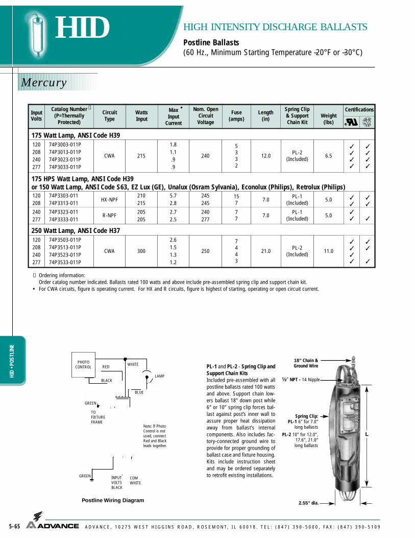
Mercury
5-65
HIDHI
D • P
OSTL
INE
HIGH INTENSITY DISCHARGE BALLASTSPostline Ballasts(60 Hz., Minimum Starting Temperature –20°F or –30°C)
A D V A N C E , 1 0 2 7 5 W E S T H I G G I N S R O A D , R O S E M O N T, I L 6 0 0 1 8 . T E L : ( 8 4 7 ) 3 9 0 - 5 0 0 0 , F A X : ( 8 4 7 ) 3 9 0 - 5 1 0 9
✝ Ordering information:Order catalog number indicated. Ballasts rated 100 watts and above include pre-assembled spring clip and support chain kit.
• For CWA circuits, figure is operating current. For HX and R circuits, figure is highest of starting, operating or open circuit current.
InputVolts
Catalog Number(P=Thermally
Protected)
WattsInput
MaxInput
Current
Nom. OpenCircuitVoltage
Fuse(amps) Weight
(lbs)
Spring Clip& SupportChain Kit
120208240277
74P3003-011P74P3013-011P74P3023-011P74P3033-011P
CWA 215
1.81.1.9.9
240
5332
PL-2(Included) 6.5
175 HPS Watt Lamp, ANSI Code H39or 150 Watt Lamp, ANSI Code S63, EZ Lux (GE), Unalux (Osram Sylvania), Econolux (Philips), Retrolux (Philips)120208
240277
74P3303-01174P3313-011
74P3323-01174P3333-011
HX-NPF
R-NPF
210215
205205
5.72.8
2.72.5
245245
240277
157
77
PL-1(Included)
PL-1(Included)
5.0
5.0
250 Watt Lamp, ANSI Code H37120208240277
74P3503-011P74P3513-011P74P3523-011P74P3533-011P
CWA 300
2.61.51.31.2
250
7443
PL-2(Included) 11.0
✝ •Length
(in)
Certifications
12.0
7.0
7.0
21.0
✓✓✓✓
✓✓
✓✓
✓✓✓✓
✓✓✓✓
✓✓
✓
✓✓
✓
CircuitType
PL-1 and PL-2 - Spring Clip andSupport Chain KitsIncluded pre-assembled with allpostline ballasts rated 100 wattsand above. Support chain low-ers ballast 18” down post while6” or 10” spring clip forces bal-last against post’s inner wall toassure proper heat dissipationaway from ballast’s internalcomponents. Also includes fac-tory-connected ground wire toprovide for proper grounding ofballast case and fixture housing.Kits include instruction sheetand may be ordered separatelyto retrofit existing installations.
L
2.55” dia.
18” Chain &Ground Wire
¹�₂” NPT - 14 Nipple
GR
EE
N
WH
ITE
CO
M
BLA
CK
INP
UT
VO
LTS
TO
FIX
TU
RE
FR
AM
E
GR
EE
N
LAM
PWH
ITE
BLU
E
PH
OT
O*
CO
NT
RO
L
RE
D
BLA
CK
*Not
e: If
Pho
to C
ontr
ol is
not
use
d,co
nnec
t Red
and
Bla
ck le
ads
toge
ther
Pos
tline
Wiri
ng D
iagr
amGREEN
GREEN
WHITE
LAMP
TOFIXTUREFRAME
INPUTVOLTSBLACK
COMWHITE
Postline Wiring Diagram
Note: If PhotoControl is notused, connectRed and Blackleads together.
PHOTOCONTROL
BLUE
BLACK
RED
Spring Clip:PL-1 6” for 7.0”
long ballasts
PL-2 10” for 12.0”,17.6”, 21.0”long ballasts
175 Watt Lamp, ANSI Code H39

Metal Halide
5-66
HIDHID • POSTLINE
HIGH INTENSITY DISCHARGE BALLASTSPostline Ballasts(60 Hz., Minimum Starting Temperature –20°F or –30°C)
A D V A N C E , 1 0 2 7 5 W E S T H I G G I N S R O A D , R O S E M O N T, I L 6 0 0 1 8 . T E L : ( 8 4 7 ) 3 9 0 - 5 0 0 0 , F A X : ( 8 4 7 ) 3 9 0 - 5 1 0 9
PL-1 and PL-2 - Spring Clip andSupport Chain KitsIncluded pre-assembled with allpostline ballasts rated 100 wattsand above. Support chain low-ers ballast 18” down post while6” or 10” spring clip forces bal-last against post’s inner wall toassure proper heat dissipationaway from ballast’s internalcomponents. Also includes fac-tory-connected ground wire toprovide for proper grounding ofballast case and fixture housing.Kits include instruction sheetand may be ordered separatelyto retrofit existing installations.
L
2.55” dia.
18” Chain &Ground Wire
¹�₂” NPT - 14 Nipple
GR
EE
N
WH
ITE
CO
M
BLA
CK
INP
UT
VO
LTS
TO
FIX
TU
RE
FR
AM
E
GR
EE
N
LAM
PWH
ITE
BLU
E
PH
OT
O*
CO
NT
RO
L
RE
D
BLA
CK
*Not
e: If
Pho
to C
ontr
ol is
not
use
d,co
nnec
t Red
and
Bla
ck le
ads
toge
ther
Pos
tline
Wiri
ng D
iagr
amGREEN
GREEN
WHITE
LAMP
TOFIXTUREFRAME
INPUTVOLTSBLACK
COMWHITE
Postline Wiring Diagram
Note: If PhotoControl is notused, connectRed and Blackleads together.
PHOTOCONTROL
BLUE
✝ Ordering information:Order catalog number indicated. If spring clip and support chain kit is desired, order separately.
• For HX circuit, figure is highest of starting, operating or open circuit current.
50 Watt Lamp, ANSI Code M110
120 74P5103-01174P5104-011P
HX-NPFHX-PFC 69 1.8
1.1 260 53 6.0 PL-2
(Optional) 2012.0 ✓✓
✓✓
InputVolts
Catalog Number(P=Thermally
Protected)
CircuitType
WattsInput
MaxInput
Current
Nom. OpenCircuitVoltage
Fuse(amps)
Weight(lbs)
Max DistTo Lamp
(ft)
Spring Clip& SupportChain Kit
Certifications✝ •Length
(in)
BLACK
RED
Spring Clip:PL-1 6” for 7.0”
long ballasts
PL-2 10” for 12.0”,17.6”, 21.0”long ballasts

High Pressure Sodium
5-67
HIDHI
D • C
ORE
&CO
ILHP
S
HIGH INTENSITY DISCHARGE BALLASTSPostline Ballasts(60 Hz., Minimum Starting Temperature –40°F or –40°C)
A D V A N C E , 1 0 2 7 5 W E S T H I G G I N S R O A D , R O S E M O N T, I L 6 0 0 1 8 . T E L : ( 8 4 7 ) 3 9 0 - 5 0 0 0 , F A X : ( 8 4 7 ) 3 9 0 - 5 1 0 9
✝ Ordering information:Order catalog number indicated. Ballasts rated 100 wattsand above include pre-assembled spring clip and supportchain kit. For ballasts rated less than 100 watts, if springclip and support chain kit is desired, order separately.
* 70 watt High Pressure Sodium ballasts with 208, 240, or277 Volt inputs will always be supplied with the spring clipand chain kit.
• For CWA circuits, figure is operating current. For HX and Rcircuits, figure is highest of starting, operating or open cir-cuit current.
PL-1 and PL-2 - Spring Clip and Support Chain KitsIncluded pre-assembled with all postline ballasts rated 100watts and above. Support chain lowers ballast 18” down postwhile 6” or 10” spring clip forces ballast against post’s inner wallto assure proper heat dissipation away from ballast’s internalcomponents. Also includes factory-connected ground wire toprovide for proper grounding of ballast case and fixture hous-ing. Kits include instruction sheet and may be ordered separate-ly to retrofit existing installations.
InputVolts
Catalog Number(P=Thermally
Protected)
CircuitType
WattsInput
MaxInput
Current
Nom. OpenCircuitVoltage
Fuse(amps)
Weight(lbs)
Max DistTo Lamp
(ft)
Spring Clip& SupportChain Kit
✝ •Length
(in)
Certifications
120 74P7702-01174P7703-011P
R-NPFR-HPF 43 1.2
.8 120 32
3.03.5
50 Watt Lamp, ANSI Code S68
35 Watt Lamp, ANSI Code S76
120
120
74P7802-011 R-PFC 61
61
1.8 120
120
5 3.5
74P7803-011P R-HPF 1.3 4 4.8
70 Watt Lamp, ANSI Code S62
208240277
74P7913-011P74P7923-011P74P7933-011P
HX-HPF 97.9.8.7
208240277
222
8.5
100 Watt Lamp, ANSI Code S54
208240277
74P8013-011P74P8023-011P74P8033-011P
HX-HPF 1361.11.0.9
208240277
333
12.7 PL-2(Included)
PL-2*(Included)
PL-2(Optional)
PL-1(Optional)
PL-1(Optional)
5
10
10
10
10
150 Watt Lamp, ANSI Code S55 (55-Volt Arc Tube)
120 74P8103-01174P8104-011P
R-NPFR-HPF 178 4.6
3.6 120 129
6.07.8
PL-2(Included) 5
120 74P8002-01174P8003-011P
R-NPFR-HPF 122 3.1
2.5 120 87
5.57.3
PL-2(Included) 5
120
120
74P7902-011 R-NPF 84
84
2.2 120
120
6 3.5
74P7903-011P R-PFC 1.6 4 5.0 PL-2(Optional)
PL-1(Optional)
10
10
7.0
12.017.6
7.0
12.017.6
12.0
17.6
7.0
12.0
21.0
✓✓
✓✓
✓
✓
✓
✓
✓
✓✓✓
✓
✓
✓✓
✓✓
✓✓
✓
✓
✓
✓
✓✓
L
2.55” dia.
18” Chain &Ground Wire
¹�₂” NPT - 14 Nipple
GR
EE
N
WH
ITE
CO
M
BLA
CK
INP
UT
VO
LTS
TO
FIX
TU
RE
FR
AM
E
GR
EE
N
LAM
PWH
ITE
BLU
E
PH
OT
O*
CO
NT
RO
L
RE
D
BLA
CK
*Not
e: If
Pho
to C
ontr
ol is
not
use
d,co
nnec
t Red
and
Bla
ck le
ads
toge
ther
Pos
tline
Wiri
ng D
iagr
amGREEN
GREEN
WHITE
LAMP
TOFIXTUREFRAME
INPUTVOLTSBLACK
COMWHITE
Postline Wiring Diagram
Note: If PhotoControl is notused, connectRed and Blackleads together.
PHOTOCONTROL
BLUE
BLACK
RED
Spring Clip:PL-1
6” for 7.0” long ballasts
PL-2 10” for 12.0”,
17.6”, 21.0”long ballasts

Mercury/HPS
5-68
HIDHID
INDOORENCLOSED
HIGH INTENSITY DISCHARGE BALLASTSIndoor Enclosed Ballasts
A D V A N C E , 1 0 2 7 5 W E S T H I G G I N S R O A D , R O S E M O N T, I L 6 0 0 1 8 . T E L : ( 8 4 7 ) 3 9 0 - 5 0 0 0 , F A X : ( 8 4 7 ) 3 9 0 - 5 1 0 9
High Pressure Sodium(60 Hz., Minimum Starting Temperature –40°F or –40°C)
G
FTop view3 double
7/8" and 1 1/8"knockouts3/8" Oval Slots
E
A B C D
78ER ENCLOSEDMENSIONS
LAMP
LAMP COM
COM LINE V
TO LINE
TOP
INSULATE UNUSEDLAMP LEADS
INDIVIDUALLY FOR 600V
Fig. IE-1
LAMP
LAMP COM
COM
TOP
INSULATE UNUSED LAMP LEADS
INDIVIDUALLY FOR 600V
Fig. IE-2
120 V208 V240 V277 V
COM
DIMENSIONS
Note: Ballasts must be mounted at least 12” apart. All indoor enclosed high pressuresodium and pulse-start metal halide lamp ballasts are furnished with an Advance longlife ignitor built into the ballast can. Maximum lamp-to-ballast distance is 50 ft.(Except 1000 watt ballasts which are 75 ft). For ballasts not requiring ignitors, see page 5-50 for remote mounting considerations.• For CWA circuits, figure is operating current.★ Equipped with an auto-reset thermal protector to prevent ignitor from overheating in the
event of lamp failure.
INSULATE UNUSEDLAMP LEADFOR 600V
INSULATE UNUSEDLAMP LEADFOR 600V
CaseStyle A B C D
PC-723 11³�₈ 12 12³�₄ 13³�₄
PC-724 12¹�₁₆ 12¹¹�₁₆ 13⁷�₁₆ 14⁷�₁₆
PC-746 17³�₈ 18 18³�₄ 19³�₄ 3⁵�₁₆
3⁵�₁₆
3⁵�₁₆
E
7¹¹�₁₆
7¹¹�₁₆
6⁹�₁₆
F
5³�₄
5³�₄
4³�₄
G
480
Input Volts
CatalogNumber
CircuitType
MaximumAmbientTemp.
WattsInput
MaxInput
Current
NomOpen
CircuitVoltage
Weight(Ibs)
Fuse(amps)
200 Watt Lamp, ANSI Code S66
120/208/240/277 78E8291-001 CWA
(50 C) 295 2.5/1.5/1.3/1.1 187 7/4/
4/3 PC-724 34
120/208/240/277
480
78E8493-001
78E8443-001
CWA(40 C) 464
3.8/2.2/1.9/1.7
1.0190
10/8/5/53
PC-724 38
1000 Watt Lamp, ANSI Code S52120/208/240/277
480
78E8793-001
78E8743-001
CWA(Protected★ )
(40 C)1100
9.5/5.5/4.8/4.2
2.3435
25/15/10/10
6PC-746 60
CaseStyle( )
•
78E8940-001 CWA(50 C) 240 0.6 185 3 PC-724 31
250 Watt Lamp, ANSI Code S50
400 Watt Lamp, ANSI Code S51
WiringDia.
Certification
IE-1
IE-2
IE-2
IE-1
IE-2
IE-1
✓
✓
✓
✓
✓
✓
✓
✓
✓
Please see Metal Halide Section for Indoor Enclosed Ballasts

Mercury
5-69
HIDHID • OUTDOORW
EATHERPROOFHIGH INTENSITY DISCHARGE BALLASTSOutdoor Weatherproof Ballasts(60 Hz., Minimum Starting Temperature –20°F or –30°C)
A D V A N C E , 1 0 2 7 5 W E S T H I G G I N S R O A D , R O S E M O N T, I L 6 0 0 1 8 . T E L : ( 8 4 7 ) 3 9 0 - 5 0 0 0 , F A X : ( 8 4 7 ) 3 9 0 - 5 1 0 9
LAMP COM COM LINE V
TO LINE
Fig. OW-1
LAMP COM
TO LINE
Fig. OW-2
120 V 208 V 240 V 277 V
• For CWA circuits, figure is operating current.
LINE VLINE VLINE VLINE V
Not included with ballast. Available at no charge when ordered with ballast.
InputVolts
CatalogNumber
CircuitType
WattsInput
MaxInput
Current
NomOpen
CircuitVoltage
CertificationFuse(amps)
100 Watt Lamp, ANSI Code H38 or H44120/208/240/277 79W2591-001 CWA 125 1.1/.6/
.6/.5 250 3/2/2/2 6.6 10
250 Watt Lamp, ANSI Code H37120/208/240/277
480
79W3592-001
79W3542-001
CWA 2852.5/1.5/1.3/1.1
.7250
8/5/5/3
2
6.6 13
Height(in)
•WiringDia.
Weight(Ibs)
OW-2
OW-2
OW-1
✓
✓
✓
✓
✓
✓
SH-1 (without a hose clamp)

Metal Halide
5-70
HIDHI
D • O
UTDO
ORW
EATH
ERPR
OOF
HIGH INTENSITY DISCHARGE BALLASTSOutdoor Weatherproof Ballasts(60 Hz., Minimum Starting Temperature –20°F or –30°C)
A D V A N C E , 1 0 2 7 5 W E S T H I G G I N S R O A D , R O S E M O N T, I L 6 0 0 1 8 . T E L : ( 8 4 7 ) 3 9 0 - 5 0 0 0 , F A X : ( 8 4 7 ) 3 9 0 - 5 1 0 9
• For CWA circuits, figure is operating current.
LAMP COM COM LINE V
TO LINE
Fig. OW-1
LAMP 1 COM COM LINE V
TO LINE
Fig. OW-4
LAMP 2
NSULATE UNUSEDALTERNATE LAMP
EADS INDIVIDUALLYFOR 600V
LINE V
Not included with ballast. Available at no charge when ordered with ballast.
LAMP COM
TO LINE
Fig. OW-2
120 V 208 V 240 V 277 VLINE VLINE VLINE VLINE V
InputVolts
CatalogNumber
CircuitType
WattsInput
MaxInput
Current
NomOpen
CircuitVoltage
Weight(Ibs)
Fuse(amps)
175/150 Watt Lamp, ANSI Code M57/M107 or H39120/208/240/277 79W5590-001 CWA 210 1.8/1.1/
.9/.8 305 5/3/3/2 6.6 15
250 Watt Lamp, ANSI Code M58 or H37120/208/240/277 79W5790-001 CWA 285 2.5/1.5/
1.3/1.1 310 8/5/5/3 8.6 18
400 Watt Lamp, ANSI Code M59 or H33120/208/240/277
480
79W6091-001
79W6041-001
CWA 458
462
4.0/2.3/2.0/1.8
1.0300
10/7/5/5
4
8.6 21
Two 400 Watt Lamps, ANSI Code M59 or H33120/240 79W6351-001 CWA
(ILO)890
8.4/4.2330
25/1513.8 43
1000 Watt Lamp, ANSI Code M47 or H36120/208/240/277
480
79W6592-001
79W6542-001CWA 1080
9.0/5.2/4.5/3.9
2.3430
20/15/10/10
611.3 33
Height(in)
•WiringDia.
Certification
OW-2
OW-2
OW-2
OW-1
OW-4
OW-2
OW-1
✓
✓
✓
✓
✓
✓
✓
✓
✓
✓
✓
✓
✓
✓
1500 Watt Lamp, ANSI Code M48
OW-2
OW-1
✓
✓
✓
✓
120/208/240/277
480
79W6792-001
79W6742-001
CWA 1605
1625
13.5/7.8/6.8/5.9
3.4
45030/25/20/15
10
13.8 41
40
480 79W6341-001 2.1 7 ✓ ✓
SH-1 (without a hose clamp)

High Pressure Sodium
5-71
HIDHID • OUTDOORW
EATHERPROOFHIGH INTENSITY DISCHARGE BALLASTSOutdoor Weatherproof Ballasts(60 Hz., Minimum Starting Temperature –40°F or –40°C)
A D V A N C E , 1 0 2 7 5 W E S T H I G G I N S R O A D , R O S E M O N T, I L 6 0 0 1 8 . T E L : ( 8 4 7 ) 3 9 0 - 5 0 0 0 , F A X : ( 8 4 7 ) 3 9 0 - 5 1 0 9
All weatherproof high pressure sodium lamp ballasts are furnished with an Advance long life ignitor builtinto the ballast can. Maximum lamp-to-ballast distance is 50 ft. (except 79W8192 - distance is 35 ft and1000 watt ballasts which are 75 ft.)
LAMP COM COM LINE V
TO LINE
Fig. OW-1
Not included with ballast. Available at no charge when ordered with ballast.
• For CWA circuits, figure is operating current. For HX circuits, figure is highest of starting, operating or opencircuit current.
★ Equipped with an auto-reset thermal protector to prevent ignitor from overheating in the event of lamp failure.
InputVolts
CatalogNumber
CircuitType
WattsInput
MaxInput
Current
NomOpen
CircuitVoltage
Weight(Ibs)
Fuse(amps)
150 Watt Lamp, ANSI Code S55 (55-Volt Arc Tube)120/208/240/277 79W8192-001 HX-HPF 188 2.8/1.6/
1.4/1.3 120 10/5/5/4 8.6 12
Height(in)
•WiringDia.
Certification
OW-2 ✓ ✓
LAMP COM
TO LINE
Fig. OW-2
120 V 208 V 240 V 277 VLINE VLINE VLINE VLINE V
310 Watt Lamp, ANSI Code S67
250 Watt Lamp, ANSI Code S50120/208/240/277
480
79W8291-001
79W8241-001CWA 310
2.5/1.5/1.3/1.1
0.7187
7/4/4/32
11.314
17
240/480 79W9597-001 CWA 365 1.7/.9 175 5/3 11.3 17
400 Watt Lamp, ANSI Code S51120/208/240/277
480
79W8493-001
79W8443-001CWA 464
3.8/2.21.9/1.7
1.0190
10/8/5/53
11.3 20
1000 Watt Lamp, ANSI Code S52120/208/240//277
480
79W8793-001
79W8743-001
CWA(Protected)
★
11009.5/5.5/4.8/4.2
2.3435
25/15/10/10
613.8 34
OW-2
OW-2
OW-1
OW-2
OW-1
OW-2
OW-1
✓
✓
✓
✓
✓
✓
✓
✓
✓
✓
✓
SH-1 (without a hose clamp)

SPECIALTYSPECIALTY PRODUCTS
A D V A N C E , 1 0 2 7 5 W E S T H I G G I N S R O A D , R O S E M O N T, I L 6 0 0 1 8 . T E L : ( 8 4 7 ) 3 9 0 - 5 0 0 0 , F A X : ( 8 4 7 ) 3 9 0 - 5 1 0 9 6-1
Customer Support/Technical Service(800) 372-3331 • (+) 1 847 390-5000 (Specialty)
Visit our web site at www.advancetransformer.com
Contents
Specialty Fluorescent and HID Ballasts and LED Drivers
Residential Lighting ............................................................................6-4Ballasts that meet FCC Consumer limits and can be used in
Energy Star Fixtures
UV Disinfection ....................................................................................6-5Ballast for Germicidal/UV lamps
Refrigeration, Tanning and Display Lighting......................................6-6Ballasts for T8 and T12/HO lampsBallast Dimensions and Wiring Diagrams..................................6-7 to 6-8
International Ballasts (Locations other than North America)
High Frequency Electronic Fluorescent BallastsGeneral Information ........................................................................6-9Ballasts for Rapid Start, HO & CFL Lamps .......................6-10 to 6-12
Electromagnetic Fluorescent BallastsGeneral Information ......................................................................6-13Ballasts for Rapid Start, HO, Slimline & Preheat Lamps ..6-14 to 6-17
Electromagnetic HID BallastsGeneral Information ......................................................................6-1850 Hz Core & Coil for Ballasts ..........................................6-19 to 6-21
Mercury - Metal Halide - High Pressure Sodium lamps60 Hz Core & Coil (Southern Japan).............................................6-22
Mercury - Metal Halide50 Hz Core & Coil (Northern Japan) .............................................6-23
Mercury - Metal Halide
LED Electronic DriversXitaniumTM LED Drivers for Europe ......................................................6-24
Corporate Offices(800) 322-2086

SPEC
IALT
Y RE
SIDE
NTIA
L
A D V A N C E , 1 0 2 7 5 W E S T H I G G I N S R O A D , R O S E M O N T, I L 6 0 0 1 8 . T E L : ( 8 4 7 ) 3 9 0 - 5 0 0 0 , F A X : ( 8 4 7 ) 3 9 0 - 5 1 0 9
RESIDENTIAL BALLASTS
6-2
Fluorescent Ballasts - Electronic - AmbiStar™
Electronic Ballasts for 4-pin Compact Fluorescent and T5, T8 or T12 Linear Lamps
Advance's family of electronic ballasts specifically designed for popular fluorescent applicationsin homes and other non-commercial environments brings all of the energy-efficient benefits offluorescent lighting to residential and hospitality applications. FCC Class B EMI compliant andavailable for T5 linear (8-14W), T8 linear (17-32W), T12 linear (34W-40W) and 4-pin CFL lamps.Advance's AmbiStar ballasts are compact and lightweight, provide quick starting and save userssignificant energy costs relative to alternative lighting sources.
Features Benefits
Provides flicker-free starting
Increased energy savings over incandescent and fluorescent magnetic with no audible noise
Insures approval in residential applications
Safely removes power to the lamp(s)
Less than 1.0 second starting
Electronic design
Class B FCC EMI Rating meets Energy Starand consumer EMI requirements
End-of-Lamp life protection for T5 lampsand smaller

SPECIALTYUV DISINFECTION
UV DISINFECTION BALLASTS
A D V A N C E , 1 0 2 7 5 W E S T H I G G I N S R O A D , R O S E M O N T, I L 6 0 0 1 8 . T E L : ( 8 4 7 ) 3 9 0 - 5 0 0 0 , F A X : ( 8 4 7 ) 3 9 0 - 5 1 0 9 6-3
Electronic Ballasts for High Output (HO) GermicidalUltraviolet (UV) Lamps
In support of the growing popularity of High Output (HO) germicidal UV-C lamps--which have been proven effective at improving indoor air quality in low temperatureenvironments such as HVAC systems--Advance's PureVOLT electronic UV ballast isspecially designed to operate a variety of 800mA HO UV lamps.
PureVOLT is ideal in such applications as hospitals, food processing facilities,schools, office buildings, recreational facilities, and residences.
Features Benefits
Enables one UV ballast to operate multiple lamps
Enhances accuracy of ordering and reduces SKUrequirements
Safely removes power to the lamp(s)
Eliminates the need to reset power mains after lampreplacement
Provides extended lamp life in frequent switchingapplications
Microprocessor-controlled design
IntelliVolt® multiple-voltage technologyenables operation at any input voltage from120 to 277 volts, 50/60Hz
End-of-Lamp-Life Protection
Auto-restart
Programmed-start technology

6-4
SPEC
IALT
Y RE
SIDE
NTIA
L
A D V A N C E , 1 0 2 7 5 W E S T H I G G I N S R O A D , R O S E M O N T, I L 6 0 0 1 8 . T E L : ( 8 4 7 ) 3 9 0 - 5 0 0 0 , F A X : ( 8 4 7 ) 3 9 0 - 5 1 0 9
T4,T5,T8 & T12
HIGH POWER FACTOR SOUND RATED A
RESIDENTIAL LIGHTING
For 7 - 42W Lamps
CFL Lamps
1 or 2 120RCF-2S13-H1-LD-QS
AmbiStarQS RCF-2S13-M1-BS-QSRCF-2S13-M1-LS-QS
No. ofLamps
InputVolts Catalog NumberBallast
Family
LampStartingMethod
UL Listed Lamp Types Page No.
(1) or (2) 13W CFL 1-27, 1-29
1 or 2 120RCF-2S18-H1-LD-QS
AmbiStarQS RCF-2S18-M1-BS-QSRCF-2S18-M1-LS-QS
(1) or (2) 18W CFL 1-27, 1-30
1 or 2 120RCF-2S26-H1-LD-QS
AmbiStarQS RCF-2S26-M1-BS-QSRCF-2S26-M1-LS-QS
(1) or (2) 26W CFL(1) 32W, 42W CFL 1-28, 1-31, 1-32
1 or 2 120REB-2S18-M1-BS-DIM
AmbiStarPSREB-2S18-M1-LS-DIM
(1) or (2) 18W CFL 2-5
1 120 AmbiStarIS (1) 26W CFL(1) 18W, 24W Long Twin Tube or (1) 22W Circline
1-28, 1-31, 1-341-42, 1-67RMB-1P26-S2
1 120RMB-1P13-L2
AmbiStarIS RMB-1P13-S1RMB-1P13-S2-H
1-26, 1-27, 1-29,1-40, 1-41
1 or 2 120RMB-2P13-L2
AmbiStarIS RMB-2P13-S2RMB-2P13-S2-H
1-26, 1-27, 1-29,1-30, 1-40, 1-41
(1) 7W, 9W, 13W CFL(1) F8T5, F13T5, F14T5 Linear
(1) 18W or (2) 7W, 9W, 13W CFL(1) F8T5 & (1) F13T5 or (2) F8T5, F13T5, F14T5
Linear
1 or 2 120 AmbiStariS 1-44, 1-45, 1-48,1-49, 1-58, 1-59REB-2P32-SC
Linear T8 Lamps
3 or 4 120 AmbiStarIS 1-46, 1-47, 1-50,1-51, 1-60, 1-61REB-4P32-SC
(1) or (2) F17T8, F25T8, F32T8 Linear
(3) or (4) F17T8, F25T8, F32T8 Linear
1 120 StandardRS 1-67RELB-2S40-SC
Linear T12 Lamps
(2) F34T12, F40T12 Linear
Above ballasts comply with the requirements of the Federal Communications Commission (FCC) rules and requlations Title 47 CFR Part 18,Consumer (Class B) for EMI/RFI (conducted and radiated).
Above ballasts meet the ballast-controlled performance requirements in the ENERGY STAR Program Requirements for Residential Lite Fixtures
The most current list of ballasts can be found at www.advance transformer.com/resources/literature in the file "ENERGY STAR Ballast Matrix"
1 or 2 120REB-2S26-M1-BS-DIM
AmbiStarPSREB-2S26-M1-LS-DIM
(1) or (2) 26W CFL(1) 32W, 42W CFL 2-5
CFL & Linear T5 Lamps
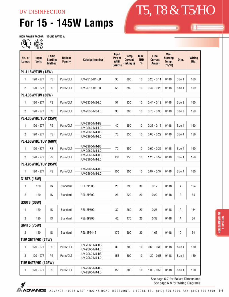
6-5
T5,T8 & T5/HO
HIGH POWER FACTOR SOUND RATED A
SPECIALTYUV DISINFECTION
UV DISINFECTION
For 15 - 145W Lamps
A D V A N C E , 1 0 2 7 5 W E S T H I G G I N S R O A D , R O S E M O N T, I L 6 0 0 1 8 . T E L : ( 8 4 7 ) 3 9 0 - 5 0 0 0 , F A X : ( 8 4 7 ) 3 9 0 - 5 1 0 9
PL-L18W/TUV (18W)
No. ofLamps
Min.StartingTemp.(°F/°C)
InputVolts Catalog NumberBallast
Family
LampStartingMethod
Line Current(Amps)
InputPowerANSI
(Watts)
LampCurrent
(mAmps)
Max.THD%
Dim. WiringDia.
1 0/-18120 - 277 IUV-2S18-H1-LDPureVOLTPS 0.26 - 0.1130 290 10 Size 1 160
2 0/-18120 - 277 IUV-2S18-H1-LDPureVOLTPS 0.47 - 0.2055 280 10 Size 1 159
1 0/-18120 - 277 IUV-2S36-M2-LDPureVOLTPS 0.44 - 0.1951 330 10 Size 2 160
2 0/-18120 - 277 IUV-2S36-M2-LDPureVOLTPS 0.78 - 0.3390 285 10 Size 2 159
1 0/-18120 - 277IUV-2S60-M4-BS
PureVOLTPS 0.35 - 0.1540 850 10 Size 4 160IUV-2S60-M4-LD
PL-L36W/TUV (36W)
PL-L35WHO/TUV (35W)
2 0/-18120 - 277IUV-2S60-M4-BS
PureVOLTPS 0.68 - 0.2978 850 10 Size 4 159IUV-2S60-M4-LD
1 0/-18120 - 277IUV-2S60-M4-BS
PureVOLTPS 0.60 - 0.2670 850 10 Size 4 160IUV-2S60-M4-LD
PL-L60WHO/TUV (60W)
2 0/-18120 - 277IUV-2S60-M4-BS
PureVOLTPS 1.20 - 0.52138 850 10 Size 4 159IUV-2S60-M4-LD
1 0/-18120 - 277IUV-2S60-M4-BS
PureVOLTPS 0.87 - 0.37100 800 10 Size 4 160IUV-2S60-M4-LD
PL-L95WHO/TUV (95W)
G15T8 (15W)
1 0/-18120 REL-2P30GStandardIS 0.1720 290 30 A *64
2 0/-18120 REL-2P30GStandardIS 0.2226 220 20 A 64
G30T8 (30W)
1 0/-18120 REL-2P30GStandardIS 0.2530 260 20 A *64
2 0/-18120 REL-2P30GStandardIS 0.3845 470 20 A 64
G64T5 (75W)
2 0/-18120 REL-2P64-ISStandardIS 1.65179 500 20 C 64
TUV 36T5/HO (75W)
1 0/-18120 - 277 IUV-2S60-M4-BSPureVOLTPS 0.69 - 0.3080 800 10 Size 4 160
2 0/-18120 - 277 IUV-2S60-M4-BSPureVOLTPS 1.30 - 0.56155 800 10 Size 4 159
IUV-2S60-M4-LD
IUV-2S60-M4-LD
TUV 64T5/HO (145W)
1 0/-18120 - 277 IUV-2S60-M4-BSPureVOLTPS 1.30 - 0.56155 800 10 Size 4 160IUV-2S60-M4-LD
See page 6-7 for Ballast DimensionsSee page 6-8 for Wiring Diagrams

6-6
SPEC
IALT
Y RE
FRIG
ERAT
ION,
TA
NNIN
G, D
ISPA
LY
A D V A N C E , 1 0 2 7 5 W E S T H I G G I N S R O A D , R O S E M O N T, I L 6 0 0 1 8 . T E L : ( 8 4 7 ) 3 9 0 - 5 0 0 0 , F A X : ( 8 4 7 ) 3 9 0 - 5 1 0 9
T8 & T12/HO
HIGH POWER FACTOR SOUND RATED A
REFRIGERATION, TANNING AND DISPLAY
For 13 - 168W Lamps
No. ofLamps
Min.StartingTemp.(°F/°C)
InputVolts Catalog NumberBallast
Family
LampStartingMethod
Line Current(Amps)
InputPowerANSI
(Watts)
BallastFactor
Max.THD%
Dim. WiringDia.
1 -20/-18120 - 277ICN-2S54
CentiumPS 0.49 - 0.2258 1.00 10 D 73ICN-2S54-90C
F58T8 (58W)
2 -20/-18120 - 277ICN-2S54
CentiumPS 0.97 - 0.42116 1.00 10 D 74ICN-2S54-90C
3 -20/-18120 - 277ICN-4S54-90C-2LS
CentiumPS 1.43 - 0.62171 1.00 10D
*75ICN-4S54-90C-2LS-G
4 -20/-18120 - 277ICN-4S54-90C-2LS
CentiumPS 1.88 - 0.81225 1.00 10D
75ICN-4S54-90C-2LS-G
G
G
1 -20/-18120 - 277 ICN-1S80CentiumPS 0.62 - 0.2673 0.77 10 D 73
F70T8 (70W)
REFRIGERATION
No. ofLamps
Min.StartingTemp.(°F/°C)
InputVolts Catalog NumberBallast
Family
LampStartingMethod
Line Current(Amps)
InputPowerANSI
(Watts)
BallastFactor
Max.THD%
Dim. WiringDia.
2 -20/-18120 RS-2S100-TP ①MagneticRS 2.00226 1.12 15 R-9 21
F73T12/HO (1000mA) 100W
TANNING
2 -20/-18120 RS-2S200-TPMagneticRS 2.51270 0.89 20 R-11 21
F72T12/VHO (1500mA) 168W
No. ofLamps
Min.StartingTemp.(°F/°C)
InputVolts Catalog NumberBallast
Family
LampStartingMethod
Line Current(Amps)
InputPowerANSI
(Watts)
BallastFactor
Max.THD%
Dim. WiringDia.
2 0/-18120 REL-2P32-SCStandardIS 0.2428 0.95 30 B 64
F15T8/PLUS, F15T8/XL, FO13T8/XP
DISPLAY
3 0/-18120 REL-3P32-SCStandardIS 0.3440 0.95 20 B 65
4 0/-18120 REL-4P32-SCStandardIS 0.4350 0.95 20 B 66
See page 6-7 for Ballast DimensionsSee page 6-8 for Wiring Diagrams
① RS-2S100-TP is only UL approve

SPECIALTYBALLAST DIMENSIONS
A D V A N C E , 1 0 2 7 5 W E S T H I G G I N S R O A D , R O S E M O N T, I L 6 0 0 1 8 . T E L : ( 8 4 7 ) 3 9 0 - 5 0 0 0 , F A X : ( 8 4 7 ) 3 9 0 - 5 1 0 9 6-7
7.00"
7.50"
1.29"
3.00"
4.20"4.60"
-LD
1.29"
3.00"
7.00"7.50"
1.29"
3.00"
2.00"
Size 4
4.20"4.60"
-LD
0.98"
2.40"Size 1 Size 2
Fig. A
113 /4” Slimline™ and HO
125/32”
27/8” 11
9 /64”
Fig. C
1.7"
1.18
"8.90"
9.5" Fig. B
Fig. D
16.34"
16.70"
1.70"
1.18
"
Fig. G
Case “R”
MLW
H
DIMENSIONS
DesignationLength (L)(inches)
Width (W)(inches)
Height (H)(inches)
Mounting (M)(inches)
R-9 11³�₄ 3³�₁₆ 2⁵�₈ 11⁹�₆₄
R-11 14³�₈ 3³�₁₆ 2⁵�₈ 13³�₄

SPEC
IALT
Y
A D V A N C E , 1 0 2 7 5 W E S T H I G G I N S R O A D , R O S E M O N T, I L 6 0 0 1 8 . T E L : ( 8 4 7 ) 3 9 0 - 5 0 0 0 , F A X : ( 8 4 7 ) 3 9 0 - 5 1 0 9
WIRING DIAGRAMS
6-8
BALLAST
Diag. 64
LAMP
WHITEBLACK
RED
BLUE
LINELAMP
BLUE
* For Single Lamp Operation, insulate unusedblue lead for 600 volts Diag. 159
Diag. 160
Diag. 21
BALLAST
Diag. 64
LAMP
WHITEBLACK
RED
BLUE
LINELAMP
BLUE
BALLAST
Diag. 66
LAMP
WHITEBLACK BLUE
LINELAMP
LAMP
BLUE
LAMP
YELLOWYELLOW
REDRED
* For Single Lamp Operation, insulate unusedblue lead for 600 volts * For Two Lamp Operation, insulate unused
blue lead for 600 volts
BALLAST
Diag. 65
LAMP
WHITEBLACK
RED
BLUE
LINELAMP
BLUE
LAMP
BLUE
* For Three Lamp Operation, insulate unusedblue lead for 600 volts
For 1 lamp operation, do not use yellow leads
* For 3-lamp operation connect lampsbetween RED and BLUE, BROWN and BLUE/WHT, YELLOW and BLUE/WHT
Diag. 73
Diag. 74
Diag. 75

INTERNATIONAL ELECTRONIC
INTERNATIONAL HIGH FREQUENCYELECTRONIC FLUORESCENT BALLASTS
A D V A N C E , 1 0 2 7 5 W E S T H I G G I N S R O A D , R O S E M O N T, I L 6 0 0 1 8 . T E L : ( 8 4 7 ) 3 9 0 - 5 0 0 0 , F A X : ( 8 4 7 ) 3 9 0 - 5 1 0 9 6-9
HF-PERFORMER BALLASTSThe HF-Performer electronic ballast is a premium performanceballast designed specifically for IEC-Specification linear and longtwin tube fluorescent lamps.
Features Include:• Programmed Rapid Start design optimizes lamp life under all
starting scenarios• Integrated Circuit-based control technology monitors lamp and
ballast conditions to ensure optimum lighting system performance• Reduced inrush current; Poke-in WAGO lead connectors• Designed to meet major European national safety and performance
standards
HF-Performer Ballast Specifications:1. Ballast shall operate from a nominal line voltage of 220 thru 240
volts, 50/60 Hz. Ballast shall maintain constant wattage outputthroughout the operating voltage range
2. Ballast shall be Programmed Start3. Ballast Power Factor shall be >96%4. Ballast Total Harmonic Distortion (THD) shall be 15%5. Ballast shall start the lamp at a min. temperature of 0°F (-15°C)6. Ballast shall be sound rated A7. Ballast shall contain no PCB’s8. Ballast shall carry a 2 year warranty when its case temperature
does not exceed 60°C9. Complies with safety regulation EN6137-2-3
10. Complies with performance regulation EN6092911. Complies with EN 55015 for EMI12. Complies with EU directive 2002/95/EC (RoHS)13. Approvals: CE
HF-BASIC BALLASTSThe HF-Basic electronic ballast is a standard performance ballastdesigned specifically for IEC-Specification TLD fluorescent lamps.
Features Include:• Instant start design provides greatest operating efficiencies• Designed to meet major European national safety and performance
standards• Poke-in WAGO lead connectors
HF-Basic Ballast Specifications:1. Ballast shall operate from a nominal line voltage of 220 thru 240
volts, 50/60 Hz. Ballast shall maintain constant wattage outputthroughout the operating voltage range
2. Ballast shall be Instant Start3. Ballast Power Factor shall be >96%4. Ballast Total Harmonic Distortion THD shall be 20%5. Ballast shall start the lamp at a min. temperature of 0°F (-15°C)6. Ballast shall be sound rated A7. Ballast shall contain no PCB’s8. Ballast shall carry a 2 year warranty when its case temperature
does not exceed 60°C9. Complies with EN6137-2-3 safety regulation
10. Complies with EN60929 performance regulation11. Complies with EN 55015 for EMI12. Complies with EU directive 2002/95/EC (RoHS)13. Approvals: CE
INTELLIVOLT BALLASTSAdvance offers many ballast featuring IntelliVolt input capability. These ballasts will operate on input voltages from 120 through 277 volts(50 or 60 Hertz). They are designed for ANSI-Specification linear and compact fluorescent lamps, but are only UL and CSA approved. The fixture or equipment manufacturer must obtain other local approvals, like CE, in order to use these ballasts in locations other thanNorth America. See Section 1 of this Atlas, for available ballasts.
The following Philips labeled electronic ballasts are available for PLL, T5, T5/HOand TLD lamps at 220-240 volts (50 or 60 Hertz).

6-10
INTE
RNAT
IONA
LEL
ECTR
ONIC
A D V A N C E , 1 0 2 7 5 W E S T H I G G I N S R O A D , R O S E M O N T, I L 6 0 0 1 8 . T E L : ( 8 4 7 ) 3 9 0 - 5 0 0 0 , F A X : ( 8 4 7 ) 3 9 0 - 5 1 0 9
PLLHIGH POWER FACTOR SOUND RATED A
INTERNATIONAL ELECTRONIC
For 36 - 55W Lamps
No. ofLamps
Min.StartingTemp.(°F/°C)
InputVolts
CatalogNumber
Ballast Family
LampStartingMethod
Line Current(Amps)
InputPowerANSI
(Watts)
BallastFactor
Max.THD%
Dim. WiringDia.
1 0/-18220 - 240 HF-PERFORMERPS 0.1637 0.95 10 A1
PLL 36W
Hz
50 - 60 HF-P 136 PLL 3
2 0/-18220 - 240 HF-PERFORMERPS 0.3070 0.95 10 A250 - 60 HF-P 236 PLL 4
1 0/-18220 - 240 HF-PERFORMERPS 0.1944 0.95 10 A1
PLL 40W
50 - 60 HF-P 140 PLL 3
2 0/-18220 - 240 HF-PERFORMERPS 0.3684 0.95 10 A250 - 60 HF-P 240 PLL 4
1 0/-18220 - 240 HF-PERFORMERPS 0.2558 0.95 10 A1
PLL 55W
50 - 60 HF-P 155 PLL 3
2 0/-18220 - 240 HF-PERFORMERPS 0.49113 0.95 10 A250 - 60 HF-P 255 PLL 4
Fig. A1 & Fig.A2
Diag. 3
Diag. 4
DIMENSIONS
Dimensions A1 A2 B1 C1
Fig. A2 11.02” 10.43” 1.18” 1.10”Fig. A1 11.02” 10.43” 1.18” 1.10”
D1
0.165”0.165”

6-11
T5 and T5HOHIGH POWER FACTOR SOUND RATED A
INTERNATIONAL ELECTRONIC
INTERNATIONAL ELECTRONIC
For 14 - 54W Lamps
A D V A N C E , 1 0 2 7 5 W E S T H I G G I N S R O A D , R O S E M O N T, I L 6 0 0 1 8 . T E L : ( 8 4 7 ) 3 9 0 - 5 0 0 0 , F A X : ( 8 4 7 ) 3 9 0 - 5 1 0 9
Refer to pages 8-32 to 8-41 for lead lengths and shipping data
Diag. 1
No. ofLamps
Min.StartingTemp.(°F/°C)
InputVolts
CatalogNumber
Ballast Family
LampStartingMethod
Line Current(Amps)
InputPowerANSI
(Watts)
BallastFactor
Max.THD%
Dim. WiringDia.
1 0/-18220 - 240 HF-PERFORMERPS 0.0818 0.95 15 A1
F14T5 (14W)
Hz
50 - 60 HF-P 1 14-35 TL5 HE 1
2 0/-18220 - 240 HF-PERFORMERPS 0.1430 0.95 15 A250 - 60 HF-P 2 14-35 TL5 HE 2
1 0/-18220 - 240 HF-PERFORMERPS 0.1125 0.95 15 A1
F21T5 (21W)
50 - 60 HF-P 1 14-35 TL5 HE 1
2 0/-18220 - 240 HF-PERFORMERPS 0.2046 0.95 15 A250 - 60 HF-P 2 14-35 TL5 HE 2
1 0/-18220 - 240 HF-PERFORMERPS 0.1533 0.95 15 A1
F28T5 (28W)
50 - 60 HF-P 1 14-35 TL5 HE 1
2 0/-18220 - 240 HF-PERFORMERPS 0.2761 0.95 15 A250 - 60 HF-P 2 14-35 TL5 HE 2
1 0/-18220 - 240 HF-PERFORMERPS 0.1840 0.95 15 A1
F35T5 (35W)
50 - 60 HF-P 1 14-35 TL5 HE 1
2 0/-18220 - 240 HF-PERFORMERPS 0.3376 0.95 15 A250 - 60 HF-P 2 14-35 TL5 HE 2
1 0/-18220 - 240 HF-PERFORMERPS 0.1228 0.95 15 A3
F24T5/HO (21W)
50 - 60 HF-P 1 24-39 TL5 HO 1
2 0/-18220 - 240 HF-PERFORMERPS 0.2249 0.95 15 A450 - 60 HF-P 2 24-39 TL5 HO 2
1 0/-18220 - 240 HF-PERFORMERPS 0.2045 0.95 15 A3
F39T5/HO (39W)
50 - 60 HF-P 1 24-39 TL5 HO 1
2 0/-18220 - 240 HF-PERFORMERPS 0.3986 0.95 15 A450 - 60 HF-P 2 24-39 TL5 HO 2
1 0/-18220 - 240 HF-PERFORMERPS 0.2761 0.95 15 A3
F54T5/HO (54W)
50 - 60 HF-P 1 54 TL5 HO 1
2 0/-18220 - 240 HF-PERFORMERPS 0.52120 0.95 15 A450 - 60 HF-P 2 54 TL5 HO 2
See page 6-12 for Ballast Dimensions
Diag. 2

6-12
INTE
RNAT
IONA
L EL
ECTR
ONIC
A D V A N C E , 1 0 2 7 5 W E S T H I G G I N S R O A D , R O S E M O N T, I L 6 0 0 1 8 . T E L : ( 8 4 7 ) 3 9 0 - 5 0 0 0 , F A X : ( 8 4 7 ) 3 9 0 - 5 1 0 9
TLDHIGH POWER FACTOR SOUND RATED A
INTERNATIONAL ELECTRONIC
For 18 - 36W Lamps
DIMENSIONS
Dimensions A1 A2 B1 C1
Fig. A2 11.02” 10.43” 1.18” 1.10”Fig. A1 11.02” 10.43” 1.18” 1.10”
D1
0.165”0.165”
Fig. A4 14.17 13.78” 1.18” 0.83”Fig. A3 14.17 13.78” 1.18” 0.83”
0.165”0.165”
No. ofLamps
Min.StartingTemp.(°F/°C)
InputVolts
CatalogNumber
Ballast Family
LampStartingMethod
Line Current(Amps)
InputPowerANSI
(Watts)
BallastFactor
Max.THD%
Dim. WiringDia.
1 0/-18220 - 240 HF-PERFORMERPS 0.0919 0.95 15 A1
TLD 18W
Hz
50 - 60 HF-P 118 TLD 1
2 0/-18220 - 240 HF-PERFORMERPS 0.1837 0.95 15 A250 - 60 HF-P 218 TLD 2
1 0/-18220 - 240 HF-BASICHF-PERFORMER
IS PS
0.160.16
3737
0.950.95
2015 A1
TLD 36W
50 - 60 HF-B 136 TLDHF-P 136 TLD 1
2 0/-18220 - 240 HF-BASICHF-PERFORMER
IS PS
0.320.31
7070
0.950.95
2015 A250 - 60 HF-B 236 TLD
HF-P 236 TLD 2
Fig. A1 & Fig.A2
Diag. 1
1 0/-18220 - 240 HF-BASICHF-PERFORMER
IS PS
0.240.24
5756
0.950.95
2015 A1
TLD 58W
50 - 60 HF-B 158 TLDHF-P 158 TLD 1
2 0/-18220 - 240 HF-BASICHF-PERFORMER
IS PS
0.480.48
110107
0.950.95
2015 A250 - 60 HF-B 258 TLD
HF-P 258 TLD 2
Fig. A3 & Fig.A4
Diag. 2

INTERNATIONALELECTROM
AGNETICINTERNATIONAL ELECTROMAGNETIC FLUORESCENT BALLASTS
A D V A N C E , 1 0 2 7 5 W E S T H I G G I N S R O A D , R O S E M O N T, I L 6 0 0 1 8 . T E L : ( 8 4 7 ) 3 9 0 - 5 0 0 0 , F A X : ( 8 4 7 ) 3 9 0 - 5 1 0 9 6-13
CERTIFICATIONS
All Advance ballasts unless otherwise indicatedbear the seal of Underwriters’ Laboratories, Inc. inaccordance with UL935 Standard for FluorescentBallasts. File No. E14927
Advance ballasts which meet the CanadianStandards Association requirements for FluorescentBallasts per CAN/CSA-22.2 No. 74-92 bear the CSAseal. File No. LR7310
Advance fluorescent ballasts are designedand manufactured in accordance with theAmerican National Standards Institute stan-dard for fluorescent ballasts, ANSI C82.1.
Norma Obligatorio Mexicana(contact your local salesperson for availability)
Supply Voltage and FrequencyEach ballast is designed to operate at the nominal voltage shown on
the ADVANCE label. Abnormal deviation from these values will resultin damage to either the ballast or lamp or both. It is therefore neces-sary that the voltage applied to ballasts be maintained within therespective limits shown in the adjoining table.
A ballast subjected to higher than nominal voltages will operate atincreased temperatures. This will result in reduced ballast life. Lowvoltage can cause premature lamp failures as well as unreliable lampstarting.
All ballasts are designed for single frequency operation. Therefore,best results will be obtained when that ballast is used on the frequencyshown on the ballast label. Frequency limitations are as follows:
Nominal Frequency Limits60HZ 57.5 to 62.550HZ 47.5 to 52.5
PrefixCode
LettersNormalVoltage
Applied VoltageLimits
Color LabelIdentification
R 120 112-127 YELLOW
X 220 210-230 GREEN
Y 240 225-250 ORANGE
M 220/250 210-230 / 235-260 —
V 277 255-290 RED
G 347 322-365 GRAY
H 120 112-127 YELLOW
L 120 112-127 YELLOW
S 120 112-127 YELLOW
Class P Ballasts — Section 410-73(e) of the National ElectricalCode (NEC) requires that all indoor fluorescent fixtures shall incor-porate ballast protection. Those fixtures employing a simple reac-tive type ballast are excepted.
The protector is located within the ballast case to prevent physi-cal damage and tampering.
Advance electromagnetic ballasts ordered with ADVAN-guard®
Class P ballast protection (TP suffix) are equipped with a thermallyactuated automatic reclosing protective device. This revolutionarydevelopment was originally designed and introduced by Advance,and today this Class P device is a requirement of the NationalElectrical Code in all indoor lighting installations.
StartingThe metal of a fluorescent fixture is a starting aid when properly
grounded. T12 Fluorescent lamps rated at 40 watts or less used forrapid or trigger start operation must be mounted within 1/2” of agrounded metal surface. T8 Lamps must be mounted within 3/4”of a grounded metal surface. All other lamps must be mountedwithin 1” of a grounded metal surface.
An important additional factor for proper lamps starting is polarity.The white ballast lead must be connected to the ground of the powersupply (neutral) and the black lead to the hot line wire. A reversal ofpolarity may result in lamp damage or improper lamp starting.
ADVANCE offers an extended range of electromagnetic fluorescent ballasts tooperate T8, T10, T12 and compact fluorescent lamps. These ballasts are suitable forInternational markets and range in voltage from 120 through 277V, 50 & 60 Hz.
NOM

6-14
INTE
RNAT
IONA
LEL
ECTR
OMAG
NETI
C
A D V A N C E , 1 0 2 7 5 W E S T H I G G I N S R O A D , R O S E M O N T, I L 6 0 0 1 8 . T E L : ( 8 4 7 ) 3 9 0 - 5 0 0 0 , F A X : ( 8 4 7 ) 3 9 0 - 5 1 0 9
T12HIGH POWER FACTOR SOUND RATED A
INTERNATIONAL ELECTROMAGNETIC
For 30 - 40W Lamps
DIMENSIONS
DesignationLength (L)(inches)
Width (W)(inches)
Height (H)(inches)
Mounting (M)(inches)
R-5 9¹�₂ 2³�₈ 1¹¹�₁₆ 8²⁹�₃₂
T-2 9¹�₂ 2³�₈ 1¹�₂ 8²⁹�₃₂
Case “R”
MLW
H
No. ofLamps
Min.StartingTemp.(°F/°C)
InputVolts
CatalogNumber
Ballast Family
LampStartingMethod
Line Current(Amps)
InputPowerANSI
(Watts)
BallastFactor
Max.THD%
Dim. WiringDia.
1 50/10220 - 250 MagneticRS 0.2450 0.88 20 R5
F30T12 (430mA) 30W
Hz
50 MTM-140-TP 18
1 60/16120 MagneticRS 0.3946 0.89 10 T260 HM-140-TP 20
0.6372 0.88 15R-2S40-TP
0.7482 0.88 25RQM-2S40-TP
0.3975 0.83 30MTM-2S40-TP
0.2978 0.91 15VQM-2S40-TP
RS Magnetic
120 60
220 or 250
277
50
60
2 60/16
T2
R5
T2
21
76
21
120 0.4553 0.95 10 T260 HM-140-TP
0.7386 0.95 15R-2S40-TP
0.8496 0.95 25RQM-2S40-TP
0.7590 0.91 20TM-2S40-TP •
0.4288 0.90 25MTM-2S40-TP
60
220 or 250
277 60
T2
T2
21
76
21
220 or 250 0.2451 0.88 20 R550 MTM-140-TP1 RS Magnetic 50/10 20
0.3391 0.96 20VQM-2S40-TP
50MagneticRS
R5
120
2 50/10
BLUEBLUE
WHITEBLK/WHTINE
BALLAST
LAMP
Diag. 20
REDRED
Diag. 21Diag. 20
BALLAST
LAMP
Diag. 18
LINEBLACKWHITE
BLUEBLUE
YEL-BLUE
220 V
250 V
REDRED
Insulate unused powerlead for 300 volts
BALLAST
LAMP
LAMP
Diag. 76
REDRED
BLUEBLUE
YELLOWYELLOW
BLACKWHITELINE
YEL-BLUE
220 V250 V
Insulate unused power leadfor 300 volts
Diag. 76
F34T12 (460mA) 34W
F40T12 (430mA) 40W
• Sound Rated B

6-15
T12/HOHIGH POWER FACTOR SOUND RATED C
INTERNATIONALELECTROM
AGNETICINTERNATIONAL ELECTROMAGNETIC
For 60 - 110W Lamps
A D V A N C E , 1 0 2 7 5 W E S T H I G G I N S R O A D , R O S E M O N T, I L 6 0 0 1 8 . T E L : ( 8 4 7 ) 3 9 0 - 5 0 0 0 , F A X : ( 8 4 7 ) 3 9 0 - 5 1 0 9
No. ofLamps
Min.StartingTemp.(°F/°C)
InputVolts
CatalogNumber
Ballast Family
LampStartingMethod
Line Current(Amps)
InputPowerANSI
(Watts)
BallastFactor
Max.THD%
Dim. WiringDia.
2 0/-18220 or 250 MagneticRS 0.70140 0.87 25 R9
F48T12/HO (800mA) 60W
Hz
50 MT-2S110-TP 21
2 0/-18220 or 250 MagneticRS 1.03224 0.93 20 R9
F72T12/HO (800mA) 85W
50 MT-2S110-TP 21
2 0/-18220 or 250 MagneticRS 1.26280 0.92 15 R9
F96T12/HO (800mA) 110W
50 MT-2S110-TP 21
DIMENSIONS
DesignationLength (L)(inches)
Width (W)(inches)
Height (H)(inches)
Mounting (M)(inches)
R-9 11³�₄ 3³�₁₆ 2⁵�₈ 11⁹�₆₄
Case “R”
MLW
H
Diag. 21

6-16
INTE
RNAT
IONA
LEL
ECTR
OMAG
NETI
C
A D V A N C E , 1 0 2 7 5 W E S T H I G G I N S R O A D , R O S E M O N T, I L 6 0 0 1 8 . T E L : ( 8 4 7 ) 3 9 0 - 5 0 0 0 , F A X : ( 8 4 7 ) 3 9 0 - 5 1 0 9
T12 Slimline
HIGH POWER FACTOR SOUND RATED C
INTERNATIONAL ELECTROMAGNETIC
For 40 - 75W Lamps
No. ofLamps
Min.StartingTemp.(°F/°C)
InputVolts
CatalogNumber
Ballast Family
LampStartingMethod
Line Current(Amps)
InputPowerANSI
(Watts)
BallastFactor
Max.THD%
Dim. WiringDia.
2 50/10120 MagneticIS 0.7563 0.84 30 R-6
F48T12 (425mA) 40W
Hz
60ADM-2E40-S
12ADM-2E40-S-TP
20/-18
120MagneticIS
1.03111 0.94 30R-8
F60T12 (425mA) 50W
60R-2E75-S-TP
12SM-2E75-S-TPVSM-2E75-S-TP277
126112
0.980.94
3025
1.100.45
50/1036
20/-18
120MagneticIS
1.07117 0.95 30R-8
F64T12 (425mA) 52W
60R-2E75-S-TP
12SM-2E75-S-TPVSM-2E75-S-TP277
126116
0.990.95
2525
1.100.45
50/1036
2 0/-18120
MagneticIS
0.810.59 45 R-6
F72T12 (425mA) 57W
60
ADM-2E75-S
12ADM-2E75-S-TPR-2E75-S-TP
277
132
130
0.94
0.98
30
25 1.200.50
50/1036
1 50/10120 MagneticIS 0.6060 0.67 50 R-560 A-175-S 10
SM-2E75-S-TPVSM-2E75-S-TP 129
85
0.93 25
1.18
50/10
R-8
2120
MagneticIS
1.050.59 40 R-6
F96T12 (425mA) 75W
60
ADM-2E75-S
12ADM-2E75-S-TPR-2E75-S-TP
277
158
170
0.94
0.97
30
25 1.400.60 36
1 50/10120 MagneticIS 0.6269 0.67 25 R-560 A-175-S 10
SM-2E75-S-TPVSM-2E75-S-TP 159
111
0.92 30
1.35 50/10R-8
DIMENSIONS
DesignationLength (L)(inches)
Width (W)(inches)
Height (H)(inches)
Mounting (M)(inches)
R-5 9¹�₂ 2³�₈ 1¹¹�₁₆ 8²⁹�₃₂
R-6 9¹�₂ 3⁷�₆₄ 1²⁵�₃₂ 8²⁹�₃₂
R-8 11³�₄ 3⁷�₆₄ 1²⁵�₃₂ 11⁹�₆₄ Case “R”
MLW
H
BALLASTBLK/WHT
Diag. 10
LINEBLUE
LAMP
WHITE
CUTOUT LAMPHOLDER
BALLASTBLACK
Diag. 12
LINE
BLUE
LAMP
WHITE
LAMP
RED
CUTOUT LAMPHOLDER
CUTOUT LAMPHOLDER
BALLAST
Diag. 36
LINE
LAMP
LAMP
CUTOUT LAMPHOLDER
CUTOUT LAMPHOLDER
RED
BLUEYELLOWYELLOW
BLACK
BROWN,WHITE orYEL-BLUE

6-17
T8,T12,T9HIGH POWER FACTOR SOUND RATED A
INTERNATIONALELECTROM
AGNETICINTERNATIONAL ELECTROMAGNETIC
For 13 - 40W Lamps
A D V A N C E , 1 0 2 7 5 W E S T H I G G I N S R O A D , R O S E M O N T, I L 6 0 0 1 8 . T E L : ( 8 4 7 ) 3 9 0 - 5 0 0 0 , F A X : ( 8 4 7 ) 3 9 0 - 5 1 0 9
No. ofLamps
Min.StartingTemp.(°F/°C)
InputVolts
CatalogNumber
Ballast Family
LampStartingMethod
Line Current(Amps)
InputPowerANSI
(Watts)
BallastFactor
Max.THD%
Dim. WiringDia.
1 0/-18220 MagneticPH 0.1226 0.89 20 T-2
F15T8 (15W)
Hz
60 XHM-1P20-TP 20
2 0/-18220 MagneticPH 0.2851 0.82 20 T-260 XM-2SP20-TP 21
1 0/-18220 MagneticPH 0.1122 0.78 15 T-2
F14T12 (14W)
60 XHM-1P20-TP 20
2 0/-18220 MagneticPH 0.2445 0.85 10 T-260 XM-2SP20-TP 21
1 0/-18220 MagneticPH 0.1123 0.86 15 T-2
F15T12 (15W)
60 XHM-1P20-TP 20
2 0/-18220 MagneticPH 0.2544 0.79 15 T-260 XM-2SP20-TP 21
1 0/-18220 MagneticPH 0.1225 0.72 20 T-2
F20T12 (20W)
60 XHM-1P20-TP 20
2 0/-18220 MagneticPH 0.2753 0.86 20 T-260 XM-2SP20-TP 21
1 50/10220 or 250 MagneticRS 0.2451 0.88 20 R-5
F16T9 (40W Circline)
50 MTM-140-TP 18
1 0/-18220 MagneticPH 0.1021 0.98 15 R-2
CFT13W/GX23 (PL-S13W, F13BX, CF13DS) or CFQ13W/GX23 (PL-C13W/USA, F13BX23T4, CF13DD)
50 XTH-1B13-TP-W 47
DIMENSIONS
DesignationLength (L)(inches)
Width (W)(inches)
Height (H)(inches)
Mounting (M)(inches)
R-2 4³�₄ 2⁷�₃₂ 1⁵�₈ 4³�₈+R-5 9¹�₂ 2³�₈ 1¹¹�₁₆ 8²⁹�₃₂
T-2 9¹�₂ 2³�₈ 1¹�₂ 8²⁹�₃₂Case “R”
MLW
H
BLUEBLUE
WHITEBLK/WHTLINE
BALLAST
LAMP
Diag. 20
REDRED
Diag. 21Diag. 20
BALLAST
LAMP
Diag. 18
LINEBLACKWHITE
BLUEBLUE
YEL-BLUE
220 V
250 V
REDRED
Insulate unused powerlead for 300 volts
BALLAST
Diag. 47
LINEWHITE
WHITE
BLACK
BLUE
BLK/WHT

SPEC
IALT
YHI
D
A D V A N C E , 1 0 2 7 5 W E S T H I G G I N S R O A D , R O S E M O N T, I L 6 0 0 1 8 . T E L : ( 8 4 7 ) 3 9 0 - 5 0 0 0 , F A X : ( 8 4 7 ) 3 9 0 - 5 1 0 9
SPECIALTY ELECTROMAGNETIC HID BALLASTS
6-18
Advance offers an extensive range of High Intensity Discharge ballasts to run ANSIspecification (U.S. style) lamps. These ballasts are suitable for Specialty marketsand range in voltage from 100 through 415V, 50 & 60 Hz.
ADVANCE® HID Lamp Ballasts are available to operate the widevariety of mercury, metal halide, high pressure sodium and low pres-sure sodium lamps available in today’s marketplace.
Like fluorescent, HID lamps are electric discharge lamps. Light isproduced by an arc discharge between two electrodes located atopposite ends of an arc tube within the lamp’s outer glass envelope.The ballast is the lamp’s power supply; its purpose is to provideproper starting and operating voltage and current to initiate and sus-tain this arc.
Core & CoilThe basic ballast is the open core & coil which is most often used
as a component within a lighting fixture. The core & coil also formsthe nucleus of the five other ballast configurations detailed in thissection. It consists of either one, two or three copper coils on a core(or “stack”) of electrical-grade steel laminations. The coils areassembled to core sections which are then surface-welded together.At Advance Transformer Co. the assembled ballast is vacuumimpregnated with a silica-filled polyester varnish to re-enforce theelectrical insulation, preclude moisture, inhibit noise, and dissipateheat. Other HID ballast manufacturers apply varnish via a preheat-and-dip process which only puts a thin coat of varnish on the outersurface of the ballast.
Encapsulated Core & CoilWhere quiet performance is required, the standard open core &
coil ballasts are encapsulated (potted) in a cube-shaped steel can uti-lizing Class H (180°C) polyester compound. These ballasts carry aClass A noise rating up through 175 watts and Class B for 250 and400 watts. As with the open core & coil, the capacitor (and ignitorwhere included) are mounted separately within the fixture.
Specialty Customer Support / Technical Service phone: (+) 1 847 390-5000Specialty Customer Support fax: (+) 1 847 390-5366Specialty Technical Support fax: (+) 1 847 768-7768
ReplacementsFor capacitors, see pages 4-48 to 4-49
For ignitors, see pages 4-50 to 4-53
Special VoltagesFor voltage and frequencies not shown in the charts of the follow-
ing pages, please contact your Advance Sales Representative.
CERTIFICATIONSIndicates ballast is listed by Underwriters Laboratories,
Inc. in accordance with UL 1029 Standard for HID Ballasts.Each ballast is marked appropriately.
All HID Ballasts are designed and manufacturedin accordance with the American NationalStandards Institute Standard for HID Ballasts, ANSIC82.4.
Norma Obligatorio Mexicana. (contact your local salesperson for availability)NOM
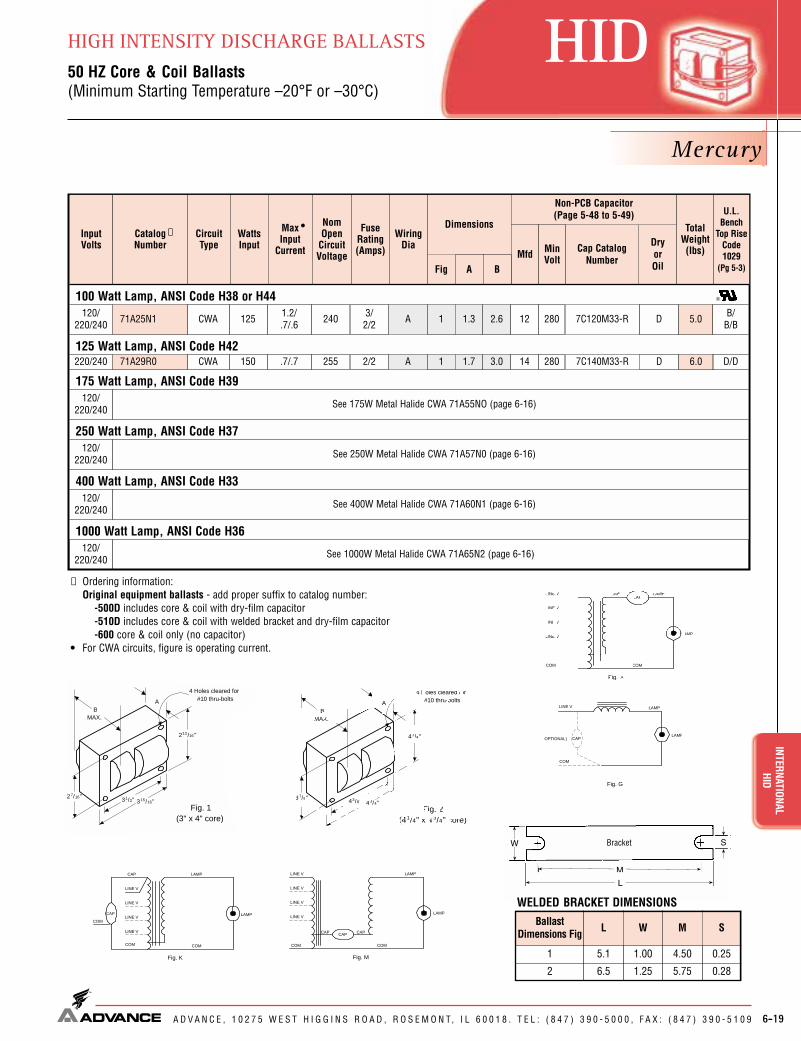
Dryor Oil
Cap CatalogNumber
Mercury
6-19
HIDINTERNATIONAL
HIDHIGH INTENSITY DISCHARGE BALLASTS50 HZ Core & Coil Ballasts(Minimum Starting Temperature –20°F or –30°C)
A D V A N C E , 1 0 2 7 5 W E S T H I G G I N S R O A D , R O S E M O N T, I L 6 0 0 1 8 . T E L : ( 8 4 7 ) 3 9 0 - 5 0 0 0 , F A X : ( 8 4 7 ) 3 9 0 - 5 1 0 9
BallastDimensions Fig L W M S
1 5.1 1.00 4.50 0.25
2 6.5 1.25 5.75 0.28
InputVolts
Catalog Number
CircuitType
WattsInput
MaxInput
Current
NomOpen
CircuitVoltage
FuseRating(Amps)
Fig
Dimensions
Non-PCB Capacitor (Page 5-48 to 5-49)
Mfd MinVolt
TotalWeight(Ibs)
U.L.Bench
Top RiseCode1029
(Pg 5-3)A B
•✝ Wiring
Dia
WELDED BRACKET DIMENSIONS
41/4"
43/8" 43/4"37/8"
BMAX.
A
Fig. 2(41/4" x 4 3/4" core)
4 Holes cleared for#10 thru-bolts
213 /16 "
31/2" 315/16"27/16"
BMAX.
A
Fig. 1(3" x 4" core)
4 Holes cleared for#10 thru-bolts
100 Watt Lamp, ANSI Code H38 or H44120/
220/240 71A25N1 CWA 125 1.2/.7/.6 240 3/
2/2 1 1.3 2.6 12 280 5.0 B/B/B
125 Watt Lamp, ANSI Code H42220/240 71A29R0 CWA 150 .7/.7 255 2/2 1 1.7 3.0 14 280 6.0 D/D
175 Watt Lamp, ANSI Code H39120/
220/240 See 175W Metal Halide CWA 71A55NO (page 6-16)
250 Watt Lamp, ANSI Code H37
400 Watt Lamp, ANSI Code H33
1000 Watt Lamp, ANSI Code H36120/
220/240 See 1000W Metal Halide CWA 71A65N2 (page 6-16)
A
A
120/220/240 See 250W Metal Halide CWA 71A57N0 (page 6-16)
120/220/240 See 400W Metal Halide CWA 71A60N1 (page 6-16)
Fig. A
LAMP
LAMP
LINE V
COM COM
LINE V
LINE V
LINE V
CAPCAP
Fig. K
LAMP
CAP LAMP
COM COM
LINE V
LINE V
COMLINE V
CAP
LINE V
Fig. M
LAMP
CAP
LAMP
COM COM
LINE V
LINE V
LINE V
LINE V
CAP CAP
Fig. G
COM
LAMP
CAPOPTIONAL)LAMP
LINE V
✝ Ordering information: Original equipment ballasts - add proper suffix to catalog number:
-500D includes core & coil with dry-film capacitor-510D includes core & coil with welded bracket and dry-film capacitor-600 core & coil only (no capacitor)
• For CWA circuits, figure is operating current.
D7C140M33-R
7C120M33-R D

54036 O
Dryor Oil
Cap CatalogNumber
D7C140M33-R
D7C175M33-R
Metal Halide
6-20
INTE
RNAT
IONA
L HI
D
A D V A N C E , 1 0 2 7 5 W E S T H I G G I N S R O A D , R O S E M O N T, I L 6 0 0 1 8 . T E L : ( 8 4 7 ) 3 9 0 - 5 0 0 0 , F A X : ( 8 4 7 ) 3 9 0 - 5 1 0 9
HID HIGH INTENSITY DISCHARGE BALLASTS50 HZ Core & Coil Ballasts(Minimum Starting Temperature –20°F or –30°C)
70 Watt Lamp, ANSI Code M98 or M143120/
220/240 71A52N2 HX-HPF 95 1.7/1.0/.9 256 5/
3/3 1 1.5 2.8 14 280 LI533-H4
120/220-240 71A55N0 CWA 210 2.0/
1.0 310 5/3 1 2.8 4.0 12 450 —
250 Watt Lamp, ANSI Code M58 or H37120/
220-240 71A57N0 CWA 290 2.5/1.3 315 7/
4
454 3.9/2.0 270 10/
5
394 3.3/1.7 280 10/
5
365 3.1/1.6 280 10/
5
2 1.9 3.4 18 400 —
400 Watt Lamp, ANSI Code M59 or H33120/
220-240 71A60N1 CWA 462 4.1/2.1 320 10/
6 2 2.2 3.7 24 450 —
1000 Watt Lamp, ANSI Code M47 or H36120/
220/240 71A65N2 CWA 1090 9.3/5.0/4.5 450 24/
13/13 8 3.0 5.0 26 525 —
1500 Watt Lamp, ANSI Code M48
220/240 71A67R2 CWA 1605 7.5/6.9 450 20/20 8a 4.4 6.4 —
K
A
A
A
A
A
B/A/B
E/E
C/C
D/A
D/D
D/C/C
120/220-240 71A58N2 Super
CWA 2 2.1 3.8 24 400 LI533-H4 A/AM
320 Watt Lamp, ANSI Code M132 or M154 (Pulse-Start)
400 Watt Lamp, ANSI Code M135 or M155 (Pulse-Start)120/
220-240 71A60N2 SuperCWA 2 2.1 3.8 30 345 LI533-H4 C/
EM
350 Watt Lamp, ANSI Code M131 (Pulse-Start)120/
220-240 71A59N3 SuperCWA 2 2.1 3.8 25.5 400 LI533-H4 C/
CM
2
15
—
—
—
2
—
2
—
12.5
5.0
32.0
9.0
11.5
12.3
14.0
12.5
23.0N
N
U.L. Bench TopRise Code 1029
(Pg 5-3)
ADVANCEClass N(200°C)
Class H(180°C)
InputVolts
CatalogNumber
CircuitType
WattsInput
MaxInput
Current
NomOpen
CircuitVoltage
FuseRating(Amps)
Fig
Dimensions
Non-PCB Capacitor(Page 5-48 to 5-49)
MinVolt
TotalWeight(Ibs)
Ignitor ✝✝(Page 5-50 to 5-53)
PartNumber
MaxDistTo
Lamp(ft)
A B
✝•
WiringDia
Mfd
—
A/A
120/220/240 71A53N0 HX-HPF 129 2.2/
1.2/1.1 280 7/4 1 1.9 3.2 17.5 300 LI533-H4K A/
A156.0 —
—
—
—
A/A/A
—
—
—
150 Watt Lamp, ANSI Code M102 or M142120/
220/240 71A54N2 HX-HPF 187 3.7/2.0/1.8 248 10/
5/5 1 2.5 4.1 28 240 LI533-H4K C/C/D57.5 —
250 Watt Lamp, ANSI Code M138 or M153 (Pulse-Start)120/
220-240 71A57N2 SuperCWA
2.6/1.4 280 6/
3 2 1.8 3.3 20 330 LI533-H4M C/C511.5 —
1000 Watt Lamp, ANSI Code M141 (Pulse-Start)120/
220/240 71A65N3 SuperCWA 1090 9.3/
5.0/4.5 450 24/13/13 8 3.0 5.0 525 LI571-H5★M D/
C/C223.0 A/A/A
New
New
New
See Wiring Diagrams on Page 6-21
294
120/220-240 71A56N3 Super
CWA 244 2.1/1.1 285 5/
3 2 1.9 3.4 17 400 LI533-H4M A/A212.5 —
200 Watt Lamp, ANSI Code M136 (Pulse-Start)
D7C280P30-R
OMD1204-100
D7C180P40-R
D7C180P40-R
D7C200P33-R
D7C240P40-R
D7C255P40-R
OMD2409-100
D7C300S34
OMD2602-100
OMD2602-100
175 Watt Lamp, ANSI Code M57 or H39; or 150 Watt Lamp, ANSI Code M107
26
2 Capacitor Set:MD1802-200
(2) 18mFd Caps Connected in Parallel[ ]

2 Capacitor Set:MD1408-230
(2) 14mFd Caps Connected in Parallel[ ]
58028 O
D7C640S28-R
D7C400P30-R
D7C175M33-R
D7C200P33-R
D7C120M33-R
D7C084L33-R
D7C060L33
Dryor Oil
Cap CatalogNumber
High Pressure Sodium
6-21
HIDINTERNATIONAL
HIDHIGH INTENSITY DISCHARGE BALLASTS50 HZ Core & Coil Ballasts(Minimum Starting Temperature –40°F or –40°C)
A D V A N C E , 1 0 2 7 5 W E S T H I G G I N S R O A D , R O S E M O N T, I L 6 0 0 1 8 . T E L : ( 8 4 7 ) 3 9 0 - 5 0 0 0 , F A X : ( 8 4 7 ) 3 9 0 - 5 1 0 9
✝ Ordering information: Original equipment ballasts - add proper suffix to catalog number:
-500D includes core & coil with dry-film capacitor-510D includes core & coil with welded bracket and dry-film capacitor-500 includes core & coil with oil-filled capacitor-510 includes core & coil with welded bracket and oil-filled capacitor-600 core & coil only (no capacitor)
✝✝ Each ballast requiring an ignitor is furnished as standard with the ShortRange ignitor model shown for use within fixtures. If a Long Range ignitoris required for remote mounting, specify on order. See pages 5-50 to 5-53for additional information.
• For HX and R circuits, figure is highest of starting, operating or open circuitcurrent. For CWA circuits, figure is operating current.
★ Equipped with an auto-reset thermal protector to preventignitor from overheating in the event of lamp failure.Dual rated Class H (180°C) / ADVANCE Class N (200°C) insulation system.Refer to page 5-3 for additional information. WELDED BRACKET DIMENSIONS
41/4"
43/8" 43/4"37/8"
BMAX.
A
Fig. 2(41/4" x 4 3/4" core)
4 Holes cleared for#10 thru-bolts
41/4"43/8"
6 "
37/8"
BMAX.
A
Fig. 8(41/4" x 6" core)
8 Holes cleared for#10 thru-bolts
53/8"Fig. 8 and 8a
(4¹�₄" x 6" core)
BallastDimensions Fig L W M S
1 5.1 1.00 4.50 0.252 6.5 1.25 5.75 0.288 7.8 2.75 6.13 0.258a 7.8 4.50 6.75 0.31
213 /16 "
31/2" 315/16"27/16"
BMAX.
A
Fig. 1(3" x 4" core)
4 Holes cleared for#10 thru-bolts
213/16"
213/16"
33/8"
21/4"
B A
Fig. 4(213 /16 " x 33/8 Reactor Core )
4 Holes cleared for#10 thru-bolts
220/240 71A78R1 HX-HPF 66 .6/.5 120 2/2 1 1.3 2.6 6.0 280 LI551-H4 2 A/A
70 Watt Lamp, ANSI Code S62120/
220/240 71A79N1 HX-HPF 94 1.4/0.8/.7 125 4/
2/2 1 1.9 3.1 8.4 280 LI551-H4 2 A/A/A
100 Watt Lamp, ANSI Code S54120/
220/240 71A80N1 HX-HPF 130 2.4/1.3/1.2 120 6/
4/4 1 2.4 3.7 12 280 LI551-H4 2 A/A/A
150 Watt Lamp, ANSI Code S55120/
220/240 71A81N2 HX-HPF 188 3.0/1.7/1.6 120 8/
5/4 1 3.0 4.2 17.5 260 LI551-H4 2 C/B/B
150 Watt Lamp, ANSI Code S56220/240 71A81R6 R-HPF 175 1.4/1.5 230 4/4 4 2.2 3.7 20 240 LI501-H4 2 B/C
250 Watt Lamp, ANSI Code S50120/
220-240 71A82N1 CWA 300 2.8/1.4 190 7/
4 2 2.1 3.7 40 240 LI501-H4 2 D/C
400 Watt Lamp, ANSI Code S51
220/240 71A87R3 CWA 1100 6.0/5.6 435 15/15 8a 4.3 6.3 LI571-H5★ 2 E/E
K
K
M
K
K
G
M
120/220-240 4.12.52M10/
61904.0/2.046571A84N3 D/
D2LI501-H4
50 Watt Lamp, ANSI Code S68
15.0
5.0
6.0
8.0
7.5
6
12.0
25/32"
43/32"
BMAX.
A
Fig. 6(2" x 4 " core)
N
N
U.L. Bench TopRise Code 1029
(Pg 5-3)
ADVANCEClass N(200°C)
Class H(180°C)
InputVolts
CatalogNumber
CircuitType
WattsInput
MaxInput
Current
NomOpen
CircuitVoltage
FuseRating(Amps)
Fig
Dimensions
Non-PCB Capacitor(Page 5-48 to 5-49)
MinVolt
TotalWeight(Ibs)
Ignitor ✝✝(Page 5-50 to 5-53)
PartNumber
MaxDistTo
Lamp(ft)
A B
✝•
WiringDia
Mfd
CWA 64 280
35.5
—
—
—
—
—
—
A/A
—
Fig. 6(2" x 4" core)
Fig. 1(3" x 4" core)
Fig. 2(4¹�₄" x 4³�₄" core)
Fig. 4(2¹³�₁₆" x 3³�₈ Reactor Core)
1000 Watt Lamp, ANSI Code S52
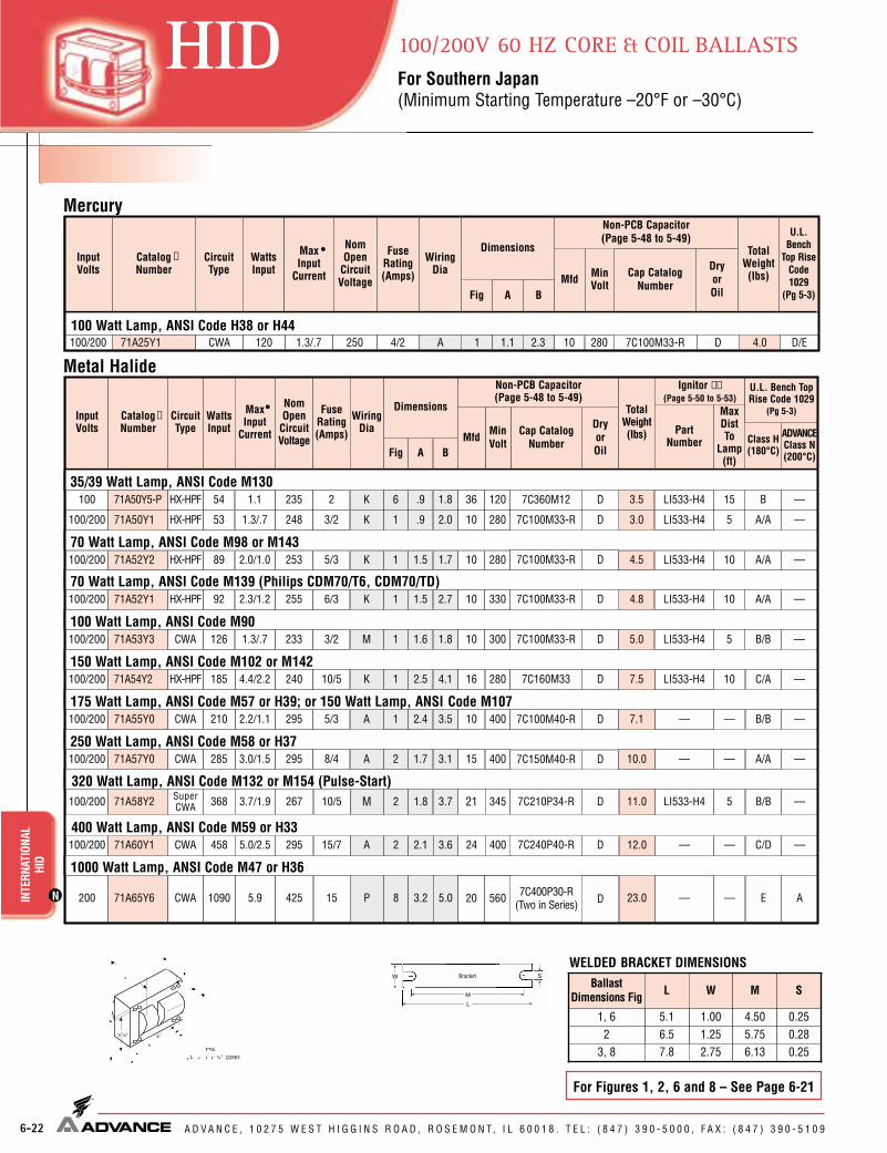
56020 D
D7C100M33-R
D7C160M33
D7C100M40-R
D7C150M40-R
D7C100M33-R
Dryor Oil
Cap CatalogNumber
Dryor Oil
Cap CatalogNumber
6-22
INTE
RNAT
IONA
L HI
D
A D V A N C E , 1 0 2 7 5 W E S T H I G G I N S R O A D , R O S E M O N T, I L 6 0 0 1 8 . T E L : ( 8 4 7 ) 3 9 0 - 5 0 0 0 , F A X : ( 8 4 7 ) 3 9 0 - 5 1 0 9
HID 100/200V 60 HZ CORE & COIL BALLASTSFor Southern Japan(Minimum Starting Temperature –20°F or –30°C)
WELDED BRACKET DIMENSIONS
1/4"43/8"
53/4"
37/8"
BMAX.
A
Fig. 3(41/4" x 5 3/4" core)
8 Holes cleared for#10 thru-bolts
11/4"
53/8"
BallastDimensions Fig L W M S
1, 6 5.1 1.00 4.50 0.252 6.5 1.25 5.75 0.28
3, 8 7.8 2.75 6.13 0.25
Mercury
Metal Halide
InputVolts
Catalog Number
CircuitType
WattsInput
MaxInput
Current
NomOpen
CircuitVoltage
FuseRating(Amps)
Fig
Dimensions
Non-PCB Capacitor (Page 5-48 to 5-49)
Mfd MinVolt
TotalWeight(Ibs)
U.L.Bench
Top RiseCode1029
(Pg 5-3)A B
•✝ Wiring
Dia
100/200 71A25Y1 CWA 120 1.3/.7 250 4/2 1 1.1 2.3 10 280 D/EA100 Watt Lamp, ANSI Code H38 or H44
4.0
100 71A50Y5-P HX-HPF 54 1.1 235 2 6 .9 1.8 36 120 LI533-H4
150 Watt Lamp, ANSI Code M102 or M142
35/39 Watt Lamp, ANSI Code M130
100/200 71A54Y2 HX-HPF 185 4.4/2.2 240 10/5 1 2.5 4.1 16 280 LI533-H4
175 Watt Lamp, ANSI Code M57 or H39; or 150 Watt Lamp, ANSI Code M107100/200 71A55Y0 CWA 210 2.2/1.1 295 5/3 1 2.4 3.5 10 400 —
250 Watt Lamp, ANSI Code M58 or H37100/200 71A57Y0 CWA 285 3.0/1.5 295 8/4 2 1.7 3.1 15 400 —
1000 Watt Lamp, ANSI Code M47 or H36
200 71A65Y6 CWA 1090 5.9 425 15 8 3.2 5.0 —
K
K
A
A
P
B
C/A
B/B
A/A
E
100/200 71A60Y1 CWA 458 2 2.1 3.6 24 400 — C/DA400 Watt Lamp, ANSI Code M59 or H33
—
15
10
—
—
—
12.0
3.5
100/200 71A52Y2 HX-HPF 89 2.0/1.0 253 5/3 1 1.5 1.7 10 280 LI533-H470 Watt Lamp, ANSI Code M98 or M143
K A/A104.5
100/200 71A53Y3 CWA 126 1.3/.7 233 3/2 1 1.6 1.8 10 300 LI533-H4100 Watt Lamp, ANSI Code M90
M B/B55.0
7.5
7.1
10.0
23.0
15/72955.0/2.5
320 Watt Lamp, ANSI Code M132 or M154 (Pulse-Start)100/200 71A58Y2 Super
CWA 368 2 1.8 3.7 21 345 LI533-H4 B/BM 511.010/52673.7/1.9
For Figures 1, 2, 6 and 8 – See Page 6-21
N
ADVANCEClass N(200°C)
Class H(180°C)
InputVolts
CatalogNumber
CircuitType
WattsInput
MaxInput
Current
NomOpen
CircuitVoltage
FuseRating(Amps)
Fig
Dimensions
Non-PCB Capacitor(Page 5-48 to 5-49)
MinVolt
TotalWeight(Ibs)
Ignitor ✝✝(Page 5-50 to 5-53)
PartNumber
MaxDistTo
Lamp(ft)
A B
✝•
WiringDia
Mfd
—
—
—
—
A
—
—
—
—
100/200 71A50Y1 HX-HPF 53 1.3/.7 248 3/2 1 .9 2.0 10 280 LI533-H4K A/A53.0 —
100/200 71A52Y1 HX-HPF 92 2.3/1.2 255 6/3 1 1.5 2.7 10 330 LI533-H470 Watt Lamp, ANSI Code M139 (Philips CDM70/T6, CDM70/TD)
K A/A104.8 —
U.L. Bench TopRise Code 1029
(Pg 5-3)
D7C100M33-R
D7C360M12
D7C100M33-R
D7C100M33-R
D7C210P34-R
D7C240P40-R
7C400P30-R(Two in Series)

OMD1204-100
D7C140M33-R
D7C120M33-R
Dryor Oil
Cap CatalogNumber
Dryor Oil
Cap CatalogNumber
6-23
HIDINTERNATIONAL
HID100/200V 50 HZ CORE & COIL BALLASTSFor Northern Japan(Minimum Starting Temperature –20°F or –30°C)
A D V A N C E , 1 0 2 7 5 W E S T H I G G I N S R O A D , R O S E M O N T, I L 6 0 0 1 8 . T E L : ( 8 4 7 ) 3 9 0 - 5 0 0 0 , F A X : ( 8 4 7 ) 3 9 0 - 5 1 0 9
InputVolts
Catalog Number
CircuitType
WattsInput
MaxInput
Current
NomOpen
CircuitVoltage
FuseRating(Amps)
Fig
Dimensions
Non-PCB Capacitor (Page 5-48 to 5-49)
Mfd MinVolt
TotalWeight(Ibs)
U.L.Bench
Top RiseCode1029
(Pg 5-3)A B
•✝ Wiring
Dia
Fig. A
LAMP
LAMP
LINE V
COM COM
LINE V
LINE V
LINE V
CAPCAP
Fig. P
LAMP 1
LAMP
LINE V
COM
LINE V
LINE V
CAPCAP
LAMP 2
Fig. K
LAMP
CAP LAMP
COM COM
LINE V
LINE V
COMLINE V
CAP
LINE V
100/200 71A25M1 CWA 125 1.3/.7 250 4/2 1 1.3 2.6 12 300 A/AA100 Watt Lamp, ANSI Code H38 or H44
4.5
Fig. M
LAMP
CAP
LAMP
COM COM
LINE V
LINE V
LINE V
LINE V
CAP CAP
Mercury
Metal Halide
InputVolts
CatalogNumber
CircuitType
WattsInput
MaxInput
Current
NomOpen
CircuitVoltage
FuseRating(Amps)
Fig
Dimensions
Non-PCB Capacitor(Page 5-48 to 5-49)
Mfd MinVolt
TotalWeight(Ibs)
Ignitor ✝✝(Page 5-50 to 5-53)
PartNumber
MaxDistTo
Lamp(ft)
U.L.Bench
TopRiseCode1029
(pg 5-3)A B
✝•
WiringDia
70 Watt Lamp, ANSI Code M98 or M143100/200 71A52M2 HX-HPF 90 1.9/1.0 258 5/3 1 1.5 1.7 14 280 LI533-H4
100/200 71A53M0 HX-HPF 129 2.9/1.5 280 7/4 1 1.9 3.2 20 240 LI533-H4
150 Watt Lamp, ANSI Code M102 or M142100/200 71A54M2 HX-HPF 185 4.4/2.2 240 10/5 1 2.5 4.1 35 240 LI533-H4
175 Watt Lamp, ANSI Code M57 or H39; or 150 Watt Lamp, ANSI Code M07100/200 71A55M0 CWA 215 2.2/1.1 295 5/3 1 3.0 4.2 12 450 —
K
K
K
A
A/A
A/A
D/D
A/A
100/200 71A60M2 CWA 460 3 2.4 4.0 26 525 — C/DA400 Watt Lamp, ANSI Code M59 or H33
—
5
15
2
—
14.0
4.5
5.8
7.5
9.0
15/72955.0/2.5
—11.0250 Watt Lamp, ANSI Code M58 or H37
100/200 71A57M0 CWA 292 3.0/1.5 295 8/4 2 1.9 3.4 18 400 — A/AA
320 Watt Lamp, ANSI Code M132 (Pulse-Start)
100/200 71A58M2 SuperCWA 370 3.7/1.9 280 10/5 2 2.1 3.9 24 400 LI533-H4 2 A/BM 12.7
✝ Ordering information: Original equipment ballasts - add proper suffix to catalog number:
-500D includes core & coil with dry-film capacitor-500 includes core & coil with oil-filled capacitor
✝✝ Each ballast requiring an ignitor is furnished as standard with the Short Range ignitor model shown for use within fixtures. If a Long Range ignitor is required for remote mounting, specify on order. See pages 5-50 to 5-53 for additional information.
• For HX circuits, figure is highest of starting, operating or open circuit current. For CWA circuits, figure is operating current.Dual rated Class H (180°C) / ADVANCE Class N (200°C) insulation system.Refer to page 5-3 for additional information.
N
35/39 Watt Lamp, ANSI Code M130100/200 71A50M1 HX-HPF 54 1.3/.7 250 3/2 1 1.1 2.2 12 280 LI533-H4K A/A53.9
70 Watt Lamp, ANSI Code M139 (Philips CDM70/T6, CDM70/TD)100/200 71A52M1 HX-HPF 90 1.9/1.0 235 5/3 1 1.5 3.0 14 300 LI533-H4K A/A105.0
D7C120M33-R
D7C140M33-R
D7C200P33-R
D7C350P24
100 Watt Lamp, ANSI Code M90
D7C180P40-R
OMD2602-100
D7C240P40-R

INTE
RNAT
IONA
LLE
D DR
IVER
S
A D V A N C E , 1 0 2 7 5 W E S T H I G G I N S R O A D , R O S E M O N T, I L 6 0 0 1 8 . T E L : ( 8 4 7 ) 3 9 0 - 5 0 0 0 , F A X : ( 8 4 7 ) 3 9 0 - 5 1 0 9
XITANIUM LED ELECTRONIC DRIVERS
6-24
CE
CatalogNumber
Certifications Nom.Line
Current(Amps)
Max.InputPower(Watts)
Max.THD%
PowerFactor
Dim./WiringDia.
Ambient Temp.
Min.(°F/°C)
LED 230V Driver Data
OutputCurrent(Adc)
12 1.0 2.8 - 33.0 0.35 -40/-40 140/60 230 LED230A0350C33F 0.07 15.0 20 0.9 Fig. C/05 Dry
12 1.0 2.8 - 33.0 0.35 -40/-40 140/60 230 LED230A0350C33FO 0.07 15.0 20 0.9 Fig. C/05 Dry, Damp
17 1.0 2.8 - 24.6 0.70 -40/-40 140/60 230 LED230A0700C24F 0.10 21.5 20 0.9 Fig. C/05 Dry
17 1.0 2.8 - 24.6 0.70 -40/-40 140/60 230 LED230A0700C24FO 0.10 21.5 20 0.9 Fig. C/05 Dry, Damp
25 3.0 2.8 - 24.6 1.05 -40/-40 140/60 230 LED230A1050C24F 0.30 25.5 20 0.9 Fig. B/02 Dry
40 5.0 2.8 - 24.6 1.75 -40/-40 140/60 230 LED230A1750C24F 0.47 40.8 20 0.9 Fig. B/02 Dry
67 10.0 2.8 - 24.0 2.80 -40/-40 140/60 230 LED230A2800C24FO 0.35 80.0 20 0.9 Fig. D/05 Dry, Damp
80 10.0 2.8 - 24.0 3.15 -40/-40 140/60 230 LED230A3150C24FO 0.48 100.0 20 0.9 Fig. D/05 Dry, Damp
Output Voltage(Vdc)
Max.OutputPower
(W)
Min.OutputVoltage(Vdc)
Max.(°F/°C)
InputVolts
Luxeon Drivers
XITANIUM LED
Env.Rating
✓
✓
✓
✓
✓
✓
✓
✓
Diag. 02Fig. B
Fig. C
Fig. D
Diag. 05
LED Drivers are specialized power supplies serving as both brain and muscle for solid-state lighting systems. Advance is the R&D leader in LED driver technology, with a wide range of innovative productsavailable today that are integral elements of high quality, energy-efficient solid-state lighting solutions.

1
LED
DRIV
ERS
XITA
NIUM
™
A D V A N C E , 1 0 2 7 5 W E S T H I G G I N S R O A D , R O S E M O N T, I L 6 0 0 1 8 . T E L : ( 8 4 7 ) 3 9 0 - 5 0 0 0 , F A X : ( 8 4 7 ) 3 9 0 - 5 1 0 9
Xitanium™ LED ELECTRONIC DRIVERS

LED DRIVERSXITANIUM
™Xitanium™ LED ELECTRONIC DRIVERS
A D V A N C E , 1 0 2 7 5 W E S T H I G G I N S R O A D , R O S E M O N T, I L 6 0 0 1 8 . T E L : ( 8 4 7 ) 3 9 0 - 5 0 0 0 , F A X : ( 8 4 7 ) 3 9 0 - 5 1 0 9 7-1
Customer Support/Technical Service(800) 372-3331 • (+) 1 847 390-5000 (International)
Visit our web site at www.advancetransformer.com
CONTENTS
General Driver Information.................................................................7-2
Driver Specifications ..........................................................................7-3
Corporate Offices(800) 322-2086

UL48
CENTIUM®
7-2
LEDLE
D DR
IVER
SXI
TANI
UM™
A D V A N C E , 1 0 2 7 5 W E S T H I G G I N S R O A D , R O S E M O N T, I L 6 0 0 1 8 . T E L : ( 8 4 7 ) 3 9 0 - 5 0 0 0 , F A X : ( 8 4 7 ) 3 9 0 - 5 1 0 9
Xitanium™ LED ELECTRONIC DRIVERS
CatalogNumber
Certifications InputCurrent
Max(A)
InputPowerMax(W)
Max.THD%
PowerFactor
Dim./WiringDia.
Min. / Max. Ambient
Temperature(°C / °F)
LED Driver Data
10.0 1.0 2.8 ~ 28.0 0.35 -40/-40 120 LED120A0350C28FO ✔ ✔ ✔ 0.12 12.5 20 0.9 Fig. A/01
12.0 1.0 2.8 ~ 32.6 0.35 120 LED120A0350C33F ✔ ✔ ✔ 0.14 15.0 20 0.9 Fig. A/01
17.2 2.0 2.8 ~ 24.6 0.70 120 LED120A0700C24F ✔ ✔ ✔ 0.20 21.5 20 0.9 Fig. A/02
17.2 2.0 2.8 ~ 24.6 0.70 120 LED120A0700C24FO ✔ ✔ ✔ 0.20 21.5 20 0.9 Fig. A02
25.5 3.0 2.8 ~ 24.6 1.05 120 LED120A0024V10F ✔ ✔ ✔ 0.30 31.9 20 0.9 Fig. B/01
40.8 5.0 2.8 ~ 24.6 1.75 120 LED120A0024V18F ✔ ✔ ✔ 0.47 51.0 20 0.9 Fig. B/01
- 120 ✔ ✔ ✔ 0.98 Fig. D/05
100.0 0.1 2.8 ~ 24.0 4.16 230 LEDINTA0024V41FO 0.51 117.0 20 0.9 Fig. D/05
- 277 ✔ ✔ ✔ 0.42 Fig. D/05
Output Voltage
(V)
Output Current(Amps)Max. Min.
InputVolts
* For complete specifications on dimming driver, see Advance, Form No. LE-6010 available at www.ledcentral.com
Luxeon™ Drivers
OutputPower (W)
12.0 2.0 12 - -40/-40 120 LED120A0012V10F ✔ ✔ ✔ 0.13 15.0 20 0.9 Fig. C/05
25.5 2.3 12 - 120 LED120A0012V21F ✔ ✔ ✔ 0.18 21.5 20 0.9 Fig. B/02
60.0 10.0 12 - 120 LED120A0012V50F ✔ ✔ ✔ 0.63 75.0 20 0.9 Fig. D/05
12 - 120 ✔ ✔ ✔ 0.61 Fig. D/05
60.0 0.1 12 - 230 LEDINTA0012V50FO 0.32 73.0 20 0.9 Fig. D/05
12 - 277 ✔ ✔ ✔ 0.26 Fig. D/05
12VDC LED Systems
17.0 2.4 24 - -40/-40 120 LED120A0024V07F ✔ ✔ ✔ 0.18 21.5 20 0.9 Fig. A/01
17.0 2.4 24 - 120 LED120A0700C24FO ✔ ✔ ✔ 0.18 21.5 20 0.9 Fig. A/02
25.5 2.3 24 - 120 LED120A0024V10F ✔ ✔ ✔ 0.27 31.9 20 0.9 Fig. B/02
40.8 5.6 24 - 120 LED120A0024V18F ✔ ✔ ✔ 0.43 51.0 20 0.9 Fig. B/05
80.0 10 24 - 120 LED120A0024V33F ✔ ✔ ✔ 0.83 100.0 20 0.9 Fig. D/05
- 120 ✔ ✔ ✔ 0.98 Fig. D/05
100.0 0.1 24 - 230 LEDINTA0024V41FO 0.51 117.0 20 0.9 Fig. D/05
- 277 ✔ ✔ ✔ 0.42 Fig. D/05
24VDC LED Systems
25.5 15 10.4 ~ 24.6 1.05 -40/-40 120 LED120A0024V10D* ✔ ✔ ✔ 0.30 31.9 20 0.9 Fig. B/03
25.5 15 24 - 120 LED120A0024V10D* ✔ ✔ ✔ 0.27 31.9 20 0.9 Fig. B/03
Dimming (0-10V Dimming)
-40°C / 60°C
-40°F / 140°F
-40°C / 60°C
-40°F / 140°F
-40°C / 60°C
-40°F / 140°F
-40°C / 60°C-40°F / 140°F
Env.Rating
Dry, Damp
Dry
Dry
Dry, Damp
Dry
Dry
Dry, Damp
Dry, Damp
Dry
Dry, Damp
Dry, Damp
Dry
Dry, Damp
Dry
Dry
Dry
Dry, Damp
Dry
Dry

7-3
LEDLED DRIVERSXITANIUM
™
A D V A N C E , 1 0 2 7 5 W E S T H I G G I N S R O A D , R O S E M O N T, I L 6 0 0 1 8 . T E L : ( 8 4 7 ) 3 9 0 - 5 0 0 0 , F A X : ( 8 4 7 ) 3 9 0 - 5 1 0 9
Xitanium™ LED ELECTRONIC DRIVERS
Diag. 01
Diag. 02
Diag. 03
Fig. A
Fig. B
Fig. C
Fig. D
Diag. 05
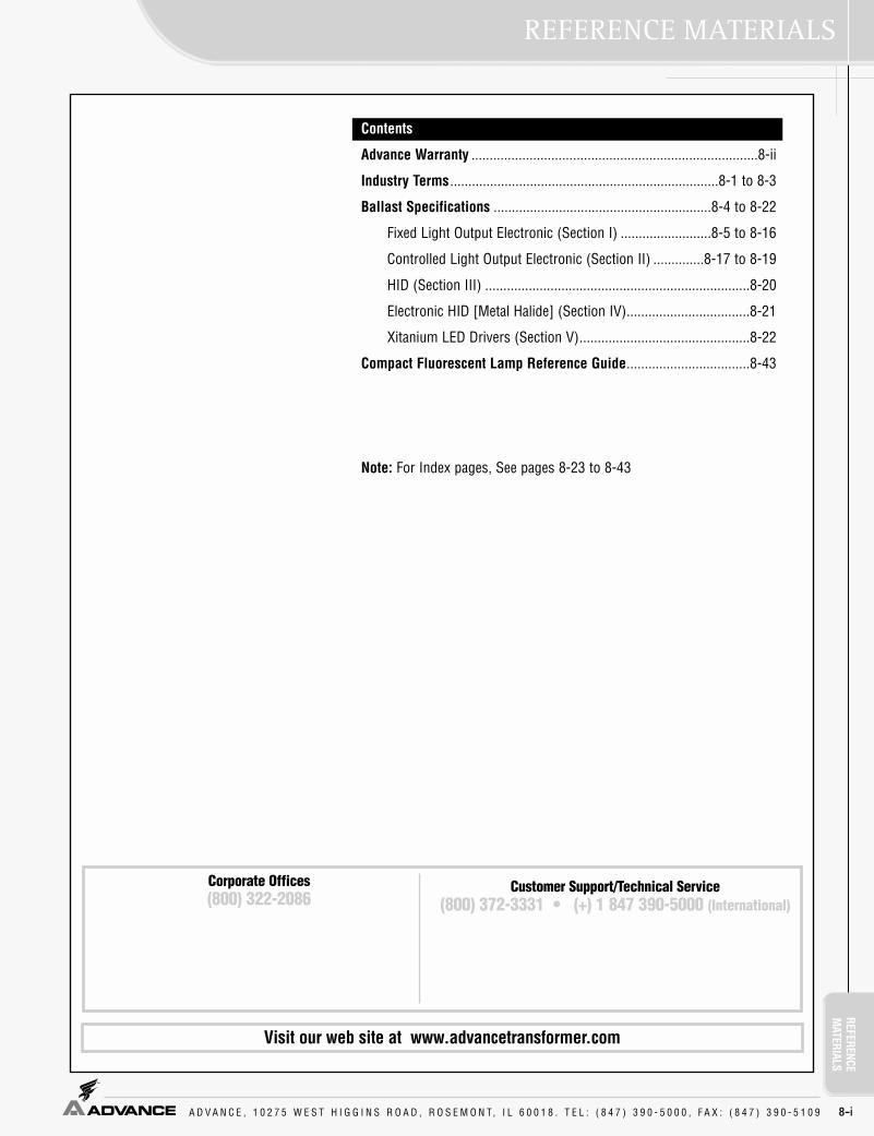
REFERENCEM
ATERIALSREFERENCE MATERIALS
A D V A N C E , 1 0 2 7 5 W E S T H I G G I N S R O A D , R O S E M O N T, I L 6 0 0 1 8 . T E L : ( 8 4 7 ) 3 9 0 - 5 0 0 0 , F A X : ( 8 4 7 ) 3 9 0 - 5 1 0 9 8-i
Customer Support/Technical Service(800) 372-3331 • (+) 1 847 390-5000 (International)
Visit our web site at www.advancetransformer.com
Contents
Advance Warranty ...............................................................................8-ii
Industry Terms ..........................................................................8-1 to 8-3
Ballast Specifications ............................................................8-4 to 8-22
Fixed Light Output Electronic (Section I) .........................8-5 to 8-16
Controlled Light Output Electronic (Section II) ..............8-17 to 8-19
HID (Section III) .........................................................................8-20
Electronic HID [Metal Halide] (Section IV)..................................8-21
Xitanium LED Drivers (Section V)...............................................8-22
Compact Fluorescent Lamp Reference Guide..................................8-43
Note: For Index pages, See pages 8-23 to 8-43
Corporate Offices(800) 322-2086

REFE
RENC
EM
ATER
IALS
A D V A N C E , 1 0 2 7 5 W E S T H I G G I N S R O A D , R O S E M O N T, I L 6 0 0 1 8 . T E L : ( 8 4 7 ) 3 9 0 - 5 0 0 0 , F A X : ( 8 4 7 ) 3 9 0 - 5 1 0 9
WARRANTY
8-ii
ADVANCE® Lamp Ballast Limited Warranty
Advance Transformer Co. (“Advance”), 10275 W. Higgins Road, Rosemont, IL 60018 warrants that its lamp ballasts will befree from defects in material and workmanship from the date of manufacture by Advance for the following periods.
This warranty is conditioned upon proper storage, instal-lation, use and maintenance. This warranty is not applicableto any ballast which is not installed and operated in accor-dance with the current edition of The National Electric Code(NEC), the Standards for Safety of Underwriters’Laboratory, Inc. (UL), the Standards for the AmericanNational Standards Institute (ANSI), and with Advance’sinstructions and guidelines for the ballast. This warranty isnot applicable to any ballast subjected to abnormal stressesand operating conditions.
Advance shall correct any defects, at Advance’s option,by either repairing any defective part or parts or by replac-ing any defective part or parts or by making available a newreplacement ballast.
The conditions of any tests concerning any ballast whichis claimed to have not performed to this warranty shall bemutually agreed upon in writing and Advance shall be noti-fied of, and may be represented at any such tests. Thisexpress limited warranty is extended by Advance only to theoriginal or first end-user purchaser.
Warranty claims are to be made in accordance withAdvance’s published Warranty Service Program.
NO IMPLIED STATUTORY WARRANTY OF MER-CHANTABILITY OR FITNESS FOR A PARTICULAR PUR-POSE SHALL APPLY BEYOND THE AFOREMENTIONEDWARRANTY PERIOD. The foregoing warranty is exclusiveof all other statutory, written or oral warranties, and noother warranties of any kind, statutory or otherwise, aregiven or herein expressed. This warranty sets forthAdvance’s responsibilities regarding the ballast andclaimant’s exclusive remedy.
LIMITATION OF LIABILITY. Advance will not under anycircumstances whether as a result of breach of contract,breach of warranty, tort, strict liability or otherwise be liablefor consequential, incidental, special or exemplary damagesincluding but not limited to, loss of profits or revenues, lossof use of ballast or any other goods or associated equip-ment or damage to any associated equipment, cost of capi-tal, cost of substitute products, facilities of services, downtime cost, or claims of claimant’s customers.
Advance’s liability on any claim of any kind for any lossor damages arising out of, resulting from or concerning anyaspect of this agreement of from the product or servicesfurnished hereunder shall not exceed the price of the spe-cific ballast or ballasts which gives rise to the claim.
This warranty gives the claimant specific legal rights.The claimant may also have other rights which vary fromstate to state.
(2) YearsStandard Magnetic FluorescentHigh Intensity Discharge (HID)Magnetic Fluorescent & HID SignMatchbox™ (case temperature 65°C or less)AmbiStar™ (case temperature 65°C or less)
(3) YearsMark III Magnetic FluorescentE-PAK™ Magnetic FluorescentCentium® Electronic 90C T5/HO (case temperature between 71°C and 90°C)SmartMate® Compact Fluorescent (case temperature between 76°C and 85°C)Electronic Sign (case temperature 90°C or less)e-Vision® Electronic HID (case temperature between 76°C and 85°C)
(5) YearsStandard Electronic (case temperature 70°C or less)Centium® Electronic (case temperature 70°C or less)Centium® Electronic 90C T5/HO (case temperature 70°C or less)Optanium™ Electronic (case temperature 70°C or less)Mark 5™ Electronic (case temperature 70°C or less)SmartMate® Compact Fluorescent (case temperature 75°C or less)PowrKut® Low Frequency Electronic (case temperature 90°C or less)Mark 7™ 0-10V Electronic Dimming (case temperature 70°C or less)Mark 10™ Powerline Electronic Dimming (case temperature 70°C or less)ROVR Electronic Dimming (case temperature 70°C or less)e-Vision® Electronic HID (case temperature 75°C or less)Xitanium® LED Drivers

A D V A N C E , 1 0 2 7 5 W E S T H I G G I N S R O A D , R O S E M O N T, I L 6 0 0 1 8 . T E L : ( 8 4 7 ) 3 9 0 - 5 0 0 0 , F A X : ( 8 4 7 ) 3 9 0 - 5 1 0 9 8-1
REFERENCEM
ATERIALSINDUSTRY TERMS
5-Tap - An HID ballast that allows for a choice of five different inputvoltagesAC (Alternating Current) - The common form of electricity frompower plant to home/office. Its direction is reversed 60 times persecond in the U.S.; 50 times in EuropeAllnGaP - The preferred LED (Light Emitting Diode) chip technolo-gy containing Aluminum, Indium, Gallium, and Phosphorous to pro-duce red, orange and amber-colors.Ambient Sound Levels - "Background noise" generated by electricalequipment operating in a building.Ambient Temperature - Temperature of the atmosphere of the sur-rounding environment.Ampere ("Amp") - A measure of electrical currentANSI (American National Standards Institute) - Group that generates voluntary product performance standards for many U.S.industries.ANSI Watts - System wattage as measured utilizing a reference bal-last and lamps on a bench top in open air as prescribed by ANSIC82.2Anti-Arc Circuit - Circuitry used to detect and limit arcing of ballastoutput leadsAnti-Striation Circuit - Circuitry used to prevent striations or spi-raling in energy saving lamps due to low temperature or low currentoperationArc (Lamp) - Intense luminous discharge formed by the passage ofelectric current across a space between electrodes.Auto-Restrike - Circuitry used to restart the lamps without resettingthe power to the ballastAutotransformer - Tapped winding transformer that changes thevoltage available to the voltage required by a particular loadBallast - Device for starting and regulating fluorescent and highintensity discharge lamps.Ballast Cycling - Undesirable condition under which the ballastturns lamps on and off (cycles) due to the overheating of the ther-mal switch inside the ballast. This may be due to incorrect lamps,improper voltage being supplied, high ambient temperature aroundthe fixture, or the early stage of ballast failure.Ballast Efficacy Factor (BEF) - Measure used to compare variouslighting systems based upon light output and power input. HigherBEF is favorable. BEF = Ballast Factor x 100 / Input WattsBallast Factor - Measure of light output from lamp operated bycommercial ballast, as compared to a laboratory standard referenceballast.Ballast Losses - Power that is supplied to the ballast but is not con-verted into light energy. Ballast Noise "Hum" - Sound made by operating Core & Coil assem-blies in both electromagnetic and electronic ballasts, generated bythe vibration of laminations in the electromagnetic field that trans-forms the voltage and current used by discharge lamps. The soundmade by high frequency electronic ballasts is lower and any noisemade by models with electronic power factor correction circuits isinaudible.Ballast Regulation - The ability of a ballast to control lamp wattage(and therefore light output) when subject to changes in line voltage.Bin - In LED's, the systematic dividing of distribution of perform-ance parameters (Flux, Color or CCT, and Vf) in to smaller groupsthat meet aesthetic requirements of the assembly.Binning - In LED's, the subdivision of the manufactured "distribution"into bins common operating parts (color, flux, forward voltage)Canadian Energy Standards - Indicates the ballast complies withthe Canadian Energy Standards and meets the requirements ofCAN/CSA-C654-M91Canadian Standards Association (CSA) - Association that gener-ates product performance and safety standards for many Canadianindustries.
Capacitor - Device in ballast that stores electrical energy.Centigrade (C) - Celsius temperature scale where 0°C = 32°F and100°C = 212°F.Chip - A very small square of semi-conducting material. Also knownas a die, it is the active light-emitting component of an LED.Circle E - Marking on ballast that shows compliance with FederalBallast Energy Law (Public Law 100-357)Coil - Windings of copper or aluminum wire surrounding a core inballast.Conformal Coating - Material that surrounds and adheres to com-ponents and protects them. Constant Wattage Autotransformer (CWA) - An HID ballast inwhich the primary and secondary coils are electrically connected.Core - Component of electromagnetic ballast that is surrounded bythe coil and comprised of steel laminations or solid ferrite material.Core & Coil Ballast - Another term for electromagnetic ballast.Crest Factor - Ratio of peak lamp current to RMS (average) lampcurrent.CSA E - Marking on ballast that shows compliance with CanadianBallast Energy Law.Cycling - See 'Ballast Cycling'DC forward current - Continuous direct current applied which isconstant over time.Decibel (dB) - Unit of measurement of the volume of soundsDie - Chip: heart of the LEDDigital Addressable Lighting Interface (DALI) - An industry standard digital protocol that allows components from differentmanufacturers (ballasts, sensors, controllers, etc.) to be mixedtogether seamlessly into complete systems.Diode - A two-electrode device with an anode and a cathode thatpasses current in only one direction. It may be designed as an elec-tron tube or as a semiconductor device.Direct Current (DC) - An electrical current flowing steadily in onedirection only.Discharge Lamp - A light producing device that depends on an elec-tric arc, rather than a filament, to create illumination.Driver - Electronics used to power illumination sources. Ballast.Efficacy - See 'System Efficacy'Electrode - See 'Filament'Electromagnetic Ballast - A low frequency (50 - 60 Hz.) ballast thatuses a "Core & Coil" assembly to transform electrical energy (volt-age and current) to start and operate fluorescent and high intensitydischarge (HID) lamps.Electromagnetic Interference(EMI) - Electrical interference (noise)generated by electrical and electronic devices. Levels generated by high frequency electronic devices are subject to regulation by the Federal Communications Commission (FCC). Twoclassifications exist Non-Consumer (also referred to as Class A orCommercial) and Consumer (also referred to as Class B orResidential).Electronic Ballast - A ballast that, with the aid of electronic components converts 60 Hz. input voltage and current to high frequency (20 kHz to 60 kHz.) to operate fluorescent and high inten-sity discharge (HID) lamps.Electronic Component - A device or part employed in an electroniccircuit to obtain some desired electronic action. Energy - Work done by an electrical system measured in watts.EOL Protection Circuit - For all T5 and smaller lamps, operatingparameters within the ballast that, when exceeded, will shutdownthe ballastETL - Independent electrical testing laboratory, which performs bal-last testing.

REFE
RENC
EM
ATER
IALS
A D V A N C E , 1 0 2 7 5 W E S T H I G G I N S R O A D , R O S E M O N T, I L 6 0 0 1 8 . T E L : ( 8 4 7 ) 3 9 0 - 5 0 0 0 , F A X : ( 8 4 7 ) 3 9 0 - 5 1 0 9
INDUSTRY TERMS
8-2
Federal Communication Commission (FCC) - The U.S. federal agencythat is charged with regulating electrical interference emissions of theelectromagnetic spectrum. The regulation entitled, "Part 18" dealswith electromagnetic interference (EMI) from all lighting devicesoperating at frequencies higher than 9 kilohertz (kHz).Feedback Signal - A feedback signal, or control signal, regulatespower through the LED driver to produce various effects in LEDs.Filament - Coated coil of special wire that emits electrons or lightwhen heated.Filament Voltage - Voltage applied to heat the lamp filament coil.Fluorescent Lamp - Gas filled lamp in which light is produced by theinteraction of an arc with phosphors lining the lamp's glass tube.Forward Current - Current through a diode in the direction of itsgreatest conduction.Forward Voltage (VF) - The voltage across a diode for a given for-ward current.Frequency - Rate of alteration in an AC current. Expressed in cyclesper second or Hertz (Hz).Fundamental Frequency - Lowest frequency in a complex wave-form. Also known as first harmonicHarmonic Distortion - A measurement of the magnitude of voltageand current harmonics as compared with the amplitude of the fun-damental frequency. Harmonic distortion can be generated by aload and fed back into the AC mains, causing distortion of the sinu-soidal waveform.Harmonics - Refers to components of the overall frequency, an inte-gral multiple of the fundamental sinewave frequency.Hertz (Hz) - Unit used to measure frequency (cycles per second) ofalternating current or voltage.High Frequency Electronic Ballast - In this book, refers to the opera-tion of electronic ballasts as frequencies > 20,000 Hertz (20 kHz)High Intensity Discharge (HID) Lamp - A discharge lamp containingan arc tube in which the active elements within (mercury, sodium,etc.) becomes vaporized (a gaseous state) within the electric arcstream to produce light.High Light Output - Ballast with a nominal ballast factor of 1.18High Power Factor Ballast - A ballast in which the power factor isgreater than 0.9 (90%). These ballasts require less line current thannormal power factor ballast. High Reactance Autotransformer Ballast (HX) - HID ballast usedwhen the input voltage does not meet the starting voltage require-ment for a lamp. The ballast will transform the input voltage to therequired level.Hot Restart Time - The time it takes a HID lamp to restart and reach90% of its light output after going from on to off to on. Typicalrestart times are 1 to 2 minutes for HPS and 5 to 20 minutes for Metal Halide.IEC (International Electrotechnical Commission) - Organizationmade up of national committees from over 60 countries that setsinternational electrical and electronics standardsIEEE (Institute of electrical and Electronics Engineers)-Organization of engineers that establishes standards for electricaland electronics industries.Ignitor (Starter) - A device used within the ballast circuit to generate high voltage electrical pulses needed to start high pressure sodium and some metal halide lampsIlluminating Engineering Society (IES) - Recognized technicalauthority on the advancement of the art and science of illuminationand its dissemination.InGaN - The preferred LED (Light Emitting Diode) semiconductortechnology containing Indium, Gallium, and Nitrogen to producegreen, blue and white-colored LED light sources.Input Power - See Input WattsInput Voltage - Voltage, provided by a power line or power supply, to the ballast or driver.
Input Watts - Total power input to the ballast that includes lampwatts and ballast losses.Inrush Current - Initial surge of current when an electrical device isturned on.Instant Start Ballast - Electromagnetic or electronic lighting circuit without lamp filament heating that produces instant light.IntelliVolt - Multi-voltage feature of Advance electronic ballasts thatallow the ballast to operate from a nominal input voltage range of120 - 277V at nominal frequencies of 50 or 60 Hz.Kilohertz (kHz) - One thousand Hertz (cycles per second).Laminations - Layers of steel, making up the ballast "core" that issurrounded by the coils in a core & coil ballast.Lamp - The lighting industry term for light bulb. It refers to the com-plete assembly including the internal parts as well as the outer bulbor tube and base(s).Lamp Current - The current delivered to the lamp by the ballast togenerate light.Lamp Current Crest Factor - See "Crest Factor."Lamp Watts (Rated) - The power consumed by the lamp to gener-ate light.Lead-Lag Slimline Ballast - Ballast that operate fluorescent lampsindependently of one another. Can start lamps at 0°F.LED Driver - See 'Driver'Light - Radiant energy that can be sensed or seen by the human eye.Visible light is measured in lumens.Light Emitting Diode (LED) - A solid-state semiconductor devicethat converts electrical energy directly into light. On its most basiclevel, the semiconductor is comprised of two regions. The p-region contains positive electrical charges while the n-region con-tains negative electrical charges. When voltage is applied and cur-rent begins to flow, the electrons move across the n region into thep region. The process of an electron moving through the p-n junc-tion releases energy. The dispersion of this energy produces pho-tons with visible wavelengths.Line Current - See AmpereLow Power Factor - See 'Normal Power Factor'Low Voltage Control - DC voltage used for signaling purposesLow Watt - Ballast with a nominal ballast factor of 0.78 or lessLumens - Measurement of light emitted by a lighted lamp.Luminaire - A complete lighting fixture consisting of a lamp (orlamps), ballast(or ballasts) as required together with the partsdesigned to distribute the light, position and protect the lamp, andconnect them to the incoming power.National Electric Code (NEC) - A nationally accepted electricalinstallation code developed by the National Fire ProtectionAssociation to reduce the risk of fire.National Electrical Manufacturers Association (NEMA) - U.S.based association that sets many common standards used in elec-trical productsNOM (Normas Oficial Mexicana) - Laboratory that sets safety stan-dards for building materials, electrical appliances and other prod-ucts for Mexico.Normal Light Output - Ballast with a nominal ballast factor of 0.88for most T8 ballasts, and 1.00 for most T5 and dimming ballasts.Normal Power Factor - Ballast in which the power factor is less than0.80 (80%). These ballasts require about twice the line current ofhigh power factor ballasts.Open Circuit Voltage [OCV] - Voltage, as measured at the lampsocket (HID or CFL) or across the lamp holders (fluorescent) whenthe lamp is not present, generated by the ballast needed to start alamp when power is turned on. Operating Position or Burn Position - The orientation of an HIDlamp in a lighting fixture such as base up, base down, horizontal, oruniversal.

REFERENCEM
ATERIALSINDUSTRY TERMS
A D V A N C E , 1 0 2 7 5 W E S T H I G G I N S R O A D , R O S E M O N T, I L 6 0 0 1 8 . T E L : ( 8 4 7 ) 3 9 0 - 5 0 0 0 , F A X : ( 8 4 7 ) 3 9 0 - 5 1 0 9 8-3
Packaged LED - Consists of the die, a lead frame, which houses thedie, the encapsulation epoxy that protectively surrounds the die, andalso disperses the light.Parallel (LED) - Electrical condition where LEDs operate under thesame voltage being provided by a driver.Parallel Circuit - Ballast circuit in which the lamps connected toone ballast operate independently of one another - if one lamp fails,the rest remain lit.PCB (Polychlorinated Biphenyls) - Chemical pollutant used incapacitors outlawed by the EPA in 1978. Ballast industry transi-tioned to non-PCB capacitors during 1979.Potting - Compound used to completely surround and cover com-ponents of some magnetic and electronic ballasts in order to protectcomponents, dampen sound, and dissipate heat.Power - The amount of energy consumed or needed by a device(ballast, lamp, or ballast plus lamp) to perform its function. Poweris measured in watts.Power Factor (PF) - A measurement of how efficiently an electricaldevice uses power supplied by the power line. PF = Watts / (Voltsx Amps). Power Factor Corrected (PFC) - Ballast with a power factor from0.80 to 0.89Powerline Control - Method of dimming control where the phase ofthe sine wave is 'chopped' to dim the lamps.Preheat Ballast - Electromagnetic ballast that requires a separatestarter in order to ignite the lampProbe Start - Method of starting mercury vapor and specific metalhalide lamps in which an additional electrode at one end of the arctube assists in lamp starting.Programmed Start Ballast - An electronic lighting circuit similar torapid start that provides precise heating of the lamp filaments andtightly controlling the preheat duration before applying starting volt-age to ignite the lamp.Pulse Start - Method of starting high pressure sodium and specificmetal halide lamps in which a high voltage starting pulse starts thelampsQuadri-Volt (Quad-Tap) - Feature within a ballast which gives you achoice of 4 different input voltagesRank - See 'Bin'Rapid Start Ballast - Electromagnetic or electronic ballast that pro-vides both filament heating and starting voltage to the lamp at thesame time in order to ignite the lamp.Reference Ballast (standard reactor) - Laboratory device used toprovide ANSI specified measurements of initial and mean lamplumens.Regulation, Lamp Wattage - The measure of the ability of a ballastor ballast circuit type to control (regulate) a lamp's operatingwattage as the input voltage varies from nominal. It is the ratio ofthe percent change in line voltage (input voltage) and the resultantpercent change in lamp wattageReverse Current - Current flowing through a diode in the directionopposite to the direction of maximum conductionReverse Voltage - Volatge across the diode for a given reverse cur-rent.RFI (Radio Frequency Interference) - Form of electromagneticinterference.Series (LED) - Electrical condition where LEDS operate under thesame current being provided by a driver.Series Circuit - Ballast circuit in which the lamps connected to oneballast operate as a group. If one lamp fails or is removed, then alllamps in the circuit turn offSeries-Sequence Slimline Ballast - Ballasts that operate withlamps starting in sequence.
Series-Parallel Circuit - Ballast circuit in which the lamps connect-ed to one ballast operate both as a group and independently. If onelamp fails or is removed in the series connected section, then alllamps in that section will turn off, but the lamps in the parallel cir-cuit remain on.Sine Wave - A mathematical function used to represent voltage andcurrent. Sound Rating - Classification given to a ballast based upon ballastnoise.Starting Temperature - The minimum ambient temperature atwhich the lamp will start. Light output may be affected due to lampcharacteristics.Striation - Spiraling or swirling of fluorescent lamps at initial turnon or energy-saving lamps at low temperature or low current.System Efficacy - Overall efficiency of the lamp/ballast system.System efficacy = total lamp lumens/system wattageThermal Protector - A self-resetting switch that disconnects powerto the ballast if internal temperatures rise above the trip point (typi-cally 105°C)Third Harmonic - Third multiple of the fundamental frequency thatwill add in the neutral wire of a three phase, 4 wire, Wye system andwill cause over heating of the neutral wire should it exceed 33 1/3percent.Three-Phase, Four-Wire Wye - Most popular electrical wiring sys-tem used today for commercial building Total Harmonic Current (THC) - The combined effect of all of theharmonic distortion on the AC waveform produced by a ballast orother device. Excessive levels of THC can create large currents onthe neutral line of a 3 phase 4 wire wye power system. SeeHarmonic Distortion.Total Harmonic Distortion (THD) - Total Harmonic Current (THC)expressed as a percentage.Transients - High voltage and resultant high current surges throughan electrical system caused by lightning strikes to nearby trans-formers, overhead lines or the ground. May also be caused byswitching of large motors or other electrical loads, as well as byshort circuits or utility system switching. Can lead to premature fail-ure of ballasts or other electrical devices.Trigger Start Ballast - Electromagnetic ballast that starts and oper-ates preheat lamps similar to a rapid start lamp. No separate starteris needed to ignite the lamp.UL (Underwriters' Laboratories, Inc.) - A not for profit organizationin the US that generates product performance and safety standardsfor electrical equipment, building materials, and other products. Enduse products such as lighting fixtures, fully encased ballasts, andhome appliances are examples of UL Listed products and bear theUL logo. Components such as HID open core & coil ballasts, elec-trical insulating materials are UL Component Recognized productsand bear the UL Component Recognition logoUR (UL Recognized) - A part or subassembly covered under UL'sRecognition Service and intended for factory installation in UL cer-tified products. They are intended for use as components of com-plete equipment submitted for investigation by UL.Voltage - A measurement of the electromotive force (electrical pres-sure) in an electrical circuit or device expressed in volts. Voltage canbe thought of as being analogous to the pressure in a plumbing sys-tem.Voltage Sag - Drop in voltage levels of electrical distribution systemthat interferes with the operation of electrical and electronic equip-ment. Commonly called "Brownout". Results when demand for elec-tricity exceeds capacity of the distribution system.Watt - The unit of measurement of electrical power. Watts = Volts xAmps x Power Factor

REFE
RENC
EM
ATER
IALS
A D V A N C E , 1 0 2 7 5 W E S T H I G G I N S R O A D , R O S E M O N T, I L 6 0 0 1 8 . T E L : ( 8 4 7 ) 3 9 0 - 5 0 0 0 , F A X : ( 8 4 7 ) 3 9 0 - 5 1 0 9
BALLAST SPECIFICATION
8-4
MASTER SPEC. and CSI FORMAT
BALLAST SPECIFICATION FOR LIGHTING
SECTION I - FIXED LIGHT OUTPUT ELECTRONIC (FLUORESCENT)• Standard• Centium® Micro Can• Centium® T5• Centium® T8, T12 and FT5• Optanium® Dedicated Voltage• Optanium® 2.0 IntelliVolt®• Mark 5™• SmartMate™• Matchbox™• AmbiStar™• PowrKut®• PureVOLT™
SECTION II - CONTROLLABLE LIGHT OUTPUT ELECTRONIC (FLUORESCENT)• Mark 7™ 0-10V• Mark 10™ Powerline• ROVR™
SECTION III - HID (INCLUDING METAL HALIDE, HIGH PRESSURE SODIUM, LOWPRESSURE SODUIM AND MERCURY VAPOR).
SECTION IV - ELECTRONIC HID (METAL HALIDE)• e-Vision™
SECTION V - XITANIUM™ LED DRIVERS
Visit our web site at www.advancetransformer.com
Customer Support/Technical Service(800) 372-3331 • (+) 1 847 390-5000 (International)
Corporate Offices(800) 322-2086

REFERENCEM
ATERIALSBALLAST SPECIFICATION
A D V A N C E , 1 0 2 7 5 W E S T H I G G I N S R O A D , R O S E M O N T, I L 6 0 0 1 8 . T E L : ( 8 4 7 ) 3 9 0 - 5 0 0 0 , F A X : ( 8 4 7 ) 3 9 0 - 5 1 0 9 8-5
SECTION I – Fixed Light Output Electronic (Fluorescent)Ballast Specification for Electronic Fluorescent
Standard
Section I - Physical Characteristics1.1 Ballast shall be physically interchangeable with standard
electromagnetic or standard electronic ballasts, where applicable.
1.2 Ballast shall be provided with integral leads color-coded per ANSI C82.11.
Section II - Performance Requirements2.1 Ballast shall be __________ (Instant or Rapid) Start.2.2 Ballast shall provide Independent Lamp Operation (ILO)
for Instant Start ballasts allowing remaining lamp(s) to maintain full light output when one or more lamps fail.
2.3 Ballast shall contain auto restart circuitry in order to restart lamps without resetting power.
2.4 Ballast shall operate from 60 Hz input source of 120V, 277V or 347V as applicable with sustained variations of +/- 10% (voltage and frequency) with no damage to the ballast.
2.5 Ballast shall be high frequency electronic type and operate lamps at a frequency between 20 kHz and 30 kHz or above 42 kHz to avoid interference with infrared devices and eliminate visible flicker.
2.6 Ballast shall have a Power Factor greater than 0.98 for primary lamp.
2.7 Ballast shall have a minimum ballast factor for primary lamp application as follows: 0.75 for Low Watt, 0.85 for Normal Light Output, and 1.20 for High Light.
2.8 Ballast shall provide for a Lamp Current Crest Factor of 1.7 or less in accordance with lamp manufacturer recom-mendations.
2.9 Ballast input current shall have Total Harmonic Distortion (THD) of less than 20% for Standard models and THD of less than 10% for Centium models when operated at nominal line voltage with primary lamp.
2.10 Ballast shall have a Class A sound rating for all 4-foot lamps and smaller.
2.11 Ballast shall have a minimum starting temperature of _______ [-18C (0F) for standard T8 lamps, 10C (50F) for T8/HO, standard T12, Slimline T12 and Long Twin Tube lamps, 0C (32F) for Slimline T8, -29C (-20F) for T12/HO lamps,] for primary lamp application. Ballast shall have a minimum starting temperature of 60F (16C) for energy-saving T8 and T12 lamps.
2.12 Ballast shall tolerate sustained open circuit and short circuit output conditions without damage.
Section III - Regulatory Requirements3.1 Ballast shall not contain any Polychlorinated Biphenyl
(PCB).3.2 Ballast shall be Underwriters Laboratories (UL) listed,
Class P and Type 1 Outdoor; and Canadian Standards Association (CSA) certified where applicable.
3.3 Ballast shall comply with ANSI C62.41 Category A for Transient protection.
3.4 Ballast shall comply with ANSI C82.11 where applicable.3.5 Ballast shall comply with the requirements of the Federal
Communications Commission (FCC) rules and regulations, Title 47 CFR part 18, Non-Consumer (Class A) for EMI/RFI (conducted and radiated).
Section IV - Other4.1 Ballast shall be manufactured in a factory certified to ISO
9002 Quality System Standards.4.2 Ballast shall carry a five-year warranty from date of manu
facture against defects in material or workmanship, including replacement, for operation at a maximum case temperature of 70C.
4.3 Manufacturer shall have a fifteen-year history of producing electronic ballasts for the North American market.
4.4 Ballast shall be Advance part # _____________or approved equal.
Note: Energy saving T8 lamps (25W, 28W or 30W) may experience lamp striations if operated on ballasts other thanOptanium 2.0 (IOP) models. Remote or tandem wiring of energysaving T8 lamps (25W, 28W or 30W) is only recommended forOptanium 2.0 (IOP) models.

REFE
RENC
EM
ATER
IALS
A D V A N C E , 1 0 2 7 5 W E S T H I G G I N S R O A D , R O S E M O N T, I L 6 0 0 1 8 . T E L : ( 8 4 7 ) 3 9 0 - 5 0 0 0 , F A X : ( 8 4 7 ) 3 9 0 - 5 1 0 9
BALLAST SPECIFICATION
8-6
Centium® Micro Can
Section I - Physical Characteristics1.1 Ballast shall be physically interchangeable with standard
electromagnetic or standard electronic ballasts, where applicable.
1.2 Ballast shall be provided with integral leads color-coded per ANSI C82.11.
Section II - Performance Requirements2.1 Ballast shall be Instant Start.2.2 Ballast shall contain auto restart circuitry in order to restart
lamps without resetting power.2.3 Ballast shall operate from 50/60 Hz input source of 120V or
277V with sustained variations of +/- 10% (voltage and frequency) with no damage to the ballast. IntelliVolt models shall operate from 50/60 Hz input source of 120V through 277V with sustained variations of +/- 10% (voltage and frequency) with no damage to the ballast.
2.4 Ballast shall be high frequency electronic type and operate lamps at a frequency above 42 kHz to avoid interference with infrared devices and eliminate visible flicker.
2.5 Ballast shall have a Power Factor greater than 0.98 for primary lamp.
2.6 Ballast shall have a minimum ballast factor for primary lamp application as follows: 0.75 for Low Watt, 0.85 for Normal Light Output, and 1.20 for High Light.
2.7 Ballast shall provide for a Lamp Current Crest Factor of 1.7 orless in accordance with lamp manufacturer recommendations.
2.8 Ballast input current shall have Total Harmonic Distortion (THD) of less than 20% for Standard models and THD of less than 10% for Centium models when operated at nominal line voltage with primary lamp.
2.9 Ballast shall have a Class A sound rating.2.10 Ballast shall have a minimum starting temperature of -18C
(0F) for standard T8 lamps and 16C (60F) for energy-saving T8 lamps.
2.11 Ballast shall provide Lamp EOL Protection Circuit.2.12 Ballast shall tolerate sustained open circuit and short circuit
output conditions without damage.
Section III - Regulatory Requirements3.1 Ballast shall not contain any Polychlorinated Biphenyl (PCB).3.2 Ballast shall be Underwriters Laboratories (UL) listed,
Class P and Type 1 Outdoor; and Canadian Standards Association (CSA) certified where applicable.
3.3 Ballast shall comply with ANSI C62.41 Category A for Transient protection.
3.4 Ballast shall comply with ANSI C82.11 where applicable.3.5 Ballast shall comply with the requirements of the Federal
Communications Commission (FCC) rules and regulations, Title 47 CFR part 18, Non-Consumer (Class A) for EMI/RFI (conducted and radiated).
Section IV - Other4.1 Ballast shall be manufactured in a factory certified to
ISO 9002 Quality System Standards.4.2 Ballast shall carry a five-year warranty from date of
manufacture against defects in material or workmanship, including replacement, for operation at a maximum case temperature of 70C.
4.3 Manufacturer shall have a fifteen-year history of producing electronic ballasts for the North American market.
4.4 Ballast shall be Advance part # _____________ or approved equal.
Note: Energy saving T8 lamps (25W, 28W or 30W) may experience lamp striations if operated on ballasts other thanOptanium 2.0 (IOP) models. Remote or tandem wiring of energysaving T8 lamps (25W, 28W or 30W) is only recommended forOptanium 2.0 (IOP) models.
SECTION I – Fixed Light Output Electronic (Fluorescent)Ballast Specification for Electronic Fluorescent

REFERENCEM
ATERIALSBALLAST SPECIFICATION
A D V A N C E , 1 0 2 7 5 W E S T H I G G I N S R O A D , R O S E M O N T, I L 6 0 0 1 8 . T E L : ( 8 4 7 ) 3 9 0 - 5 0 0 0 , F A X : ( 8 4 7 ) 3 9 0 - 5 1 0 9 8-7
Centium® T5
Section I - Physical Characteristics1.1 Ballast shall be physically interchangeable with standard
electromagnetic or standard electronic ballasts, where applicable.
1.2 Ballast shall be provided with integral leads or poke-in wire trap connectors color-coded per ANSI C82.11.
Section II - Performance Requirements2.1 Ballast shall be Programmed Start.2.2 Ballast shall contain auto restart circuitry in order to restart
lamps without resetting power.2.3 Ballast shall operate from 50/60 Hz input source of
___________________ (120V through 277V or 347V through 480V) with sustained variations of +/- 10% (voltage and frequency) with no damage to the ballast.
2.4 Ballast shall be high frequency electronic type and operate lamps at a frequency above 42 kHz to avoid interference with infrared devices and eliminate visible flicker.
2.5 Ballast shall have a Power Factor greater than 0.98 for primary lamp.
2.6 Ballast shall have a minimum ballast factor of 1.00 for primary lamp application.
2.7 Ballast shall provide for a Lamp Current Crest Factor of 1.7 orless in accordance with lamp manufacturer recommendations.
2.8 Ballast input current shall have Total Harmonic Distortion (THD) of less than 20% for Standard models and THD of less than 10% for Centium models when operated at nominal line voltage with primary lamp.
2.9 Ballast shall have a Class A sound rating.2.10 Ballast shall have a minimum starting temperature of
_______ {-18C (0F) or -28C (-20F)} for primary lamp.2.11 Ballast shall provide Lamp EOL Protection Circuit.2.12 Ballast shall tolerate sustained open circuit and short circuit
output conditions without damage.2.13 Ballast shall have a hi-low switching option when operating
(4) F54T5/HO lamps to allow switching from 4-2 lamps, 3-2 lamps or 3-1 lamp.
2.14 Four-lamp ballast shall have semi-independent lamp operation.
Section III - Regulatory Requirements3.1 Ballast shall not contain any Polychlorinated Biphenyl (PCB).3.2 Ballast shall be Underwriters Laboratories (UL) listed,
Class P and Type 1 Outdoor; and Canadian Standards Association (CSA) certified where applicable.
3.3 Ballast shall comply with ANSI C62.41 Category A for Transient protection.
3.4 Ballast shall comply with ANSI C82.11 where applicable.3.5 Ballast shall comply with the requirements of the Federal
Communications Commission (FCC) rules and regulations, Title 47 CFR part 18, Non-Consumer (Class A) for EMI/RFI (conducted and radiated).
3.6 Ballast shall comply with UL Type CC rating.
Section IV - Other4.1 Ballast shall be manufactured in a factory certified to
ISO 9002 Quality System Standards.4.2 Ballast shall carry a five-year warranty from date of
manufacture against defects in material or workmanship, including replacement, for operation at a maximum case temperature of 70C. Ballasts with a "90C" designation in their catalog number shall also carry a three-year warranty at a maximum case temperature of 90C.
4.3 Manufacturer shall have a fifteen-year history of producing electronic ballasts for the North American market.
4.4 Ballast shall be Advance part # _____________ or approved equal.
SECTION I – Fixed Light Output Electronic (Fluorescent)Ballast Specification for Electronic Fluorescent

REFE
RENC
EM
ATER
IALS
A D V A N C E , 1 0 2 7 5 W E S T H I G G I N S R O A D , R O S E M O N T, I L 6 0 0 1 8 . T E L : ( 8 4 7 ) 3 9 0 - 5 0 0 0 , F A X : ( 8 4 7 ) 3 9 0 - 5 1 0 9
BALLAST SPECIFICATION
8-8
Centium® T8, T12 & FT5
Section I - Physical Characteristics1.1 Ballast shall be physically interchangeable with standard
electromagnetic or standard electronic ballasts, whereapplicable.
1.2 Ballast shall be provided with integral leads color coded perANSI C82.11.
Section II - Performance Requirements2.1 Ballast shall be _________ (Instant, Rapid or Programmed)
Start.2.2 Ballast shall provide Independent Lamp Operation (ILO) for
Instant Start ballats allowing remaining lamp(s) to maintainfull light output when one or more lamps fail.
2.3 Ballast shall contain auto restart circuitry in order to restartlamps without resetting power (except T8/HO ballast).
2.4 Ballast shall operate from 60 Hz input source of 120V, 277Vor 347V as applicable with sustained variations of +/- 10%(voltage and frequency) with no damage to the ballast.IntelliVolt models shall operate from 50/60 Hz input sourceof 120V through 277V with sustained variations of +/- 10%(voltage and frequency) with no damage to the ballast.
2.5 Ballast shall be high frequency electronic type and operatelamps at a frequency above 42 kHz ("GCN" models between20kHz and 30kHz) to avoid interference with infrareddevices and eliminate visible flicker.
2.6 Ballast shall have a Power Factor greater than 0.98 for pri-mary lamp.
2.7 Ballast shall have a minimum ballast factor for primarylamp application as follows: 0.75 for Low Watt, 0.85 forNormal Light Output, and 1.20 for High Light.
2.8 Ballast shall provide for a Lamp Current Crest Factor of 1.7or less in accordance with lamp manufacturer recommen-dations.
2.9 Ballast input current shall have Total Harmonic Distortion(THD) of less than 20% for Standard models and THD ofless than 10% for Centium models when operated at nom-inal line voltage with primary lamp.
2.10 Ballast shall have a Class A sound rating.2.11 Ballast shall have a minimum starting temperature of
_______ [-18C (0F) for standard T8 and Long Twin Tubelamps, 10C (50F) for standard T12 lamps, 0C (32F) forSlimline T8 lamps and "GCN" models, -29C (-20F) forT8/HO lamps] for primary lamp application. Ballast shallhave a minimum starting temperature of 16C (60F) forenergy-saving T8 and T12 lamps.
2.12 Ballast shall tolerate sustained open circuit and short circuit output conditions without damage.
Section III - Regulatory Requirements3.1 Ballast shall not contain any Polychlorinated Biphenyl
(PCB).3.2 Ballast shall be Underwriters Laboratories (UL) listed, Class
P and Type 1 Outdoor; and Canadian Standards Association(CSA) certified where applicable.
3.3 Ballast shall comply with ANSI C62.41 Category A forTransient protection.
3.4 Ballast shall comply with ANSI C82.11 where applicable.3.5 Ballast shall comply with the requirements of the Federal
Communications Commission (FCC) rules and regulations,Title 47 CFR part 18, Non-Consumer (Class A) for EMI/RFI(conducted and radiated).
Section IV - Other4.1 Ballast shall be manufactured in a factory certified to ISO
9002 Quality System Standards.4.2 Ballast shall carry a five-year warranty from date of manu-
facture against defects in material or workmanship, includ-ing replacement, for operation at a maximum case temper-ature of 70C.
4.3 Manufacturer shall have a fifteen year history of producingelectronic ballasts for the North American market.
4.4 Ballast shall be Advance part # _____________ or approved equal.
Note: Energy saving T8 lamps (25W, 28W or 30W) may experience lamp striations if operated on ballasts other thanOptanium 2.0 (IOP) models. Remote or tandem wiring of energysaving T8 lamps (25W, 28W or 30W) is only recommended forOptanium 2.0 (IOP) models.
SECTION I – Fixed Light Output Electronic (Fluorescent)Ballast Specification for Electronic Fluorescent

REFERENCEM
ATERIALSBALLAST SPECIFICATION
A D V A N C E , 1 0 2 7 5 W E S T H I G G I N S R O A D , R O S E M O N T, I L 6 0 0 1 8 . T E L : ( 8 4 7 ) 3 9 0 - 5 0 0 0 , F A X : ( 8 4 7 ) 3 9 0 - 5 1 0 9 8-9
Optanium® Dedicated Voltage
Section I - Physical Characteristics1.1 Ballast shall be physically interchangeable with standard
electromagnetic or standard electronic ballasts, whereapplicable.
1.2 Ballast shall be provided with integral leads color coded perANSI C82.11.
Section II - Performance Requirements2.1 Ballast shall be Instant Start.2.2 Ballast shall provide Independent Lamp Operation (ILO) for
Instant Start ballats allowing remaining lamp(s) to maintainfull light output when one or more lamps fail.
2.3 Ballast shall contain auto restart circuitry in order to restartlamps without resetting power.
2.4 Ballast shall operate from 60 Hz input source of 120V, 277Vor 347V as applicable with sustained variations of +/- 10%(voltage and frequency) with no damage to the ballast.
2.5 Ballast shall be high frequency electronic type and operatelamps at a frequency between 42 kHz and 52kHz to avoidinterference with infrared devices, eliminate visible flicker avoid Article Surveillance Systems, such as anti-theftdevices.
2.6 Ballast shall have a Power Factor greater than 0.98 for primary lamp.
2.7 Ballast shall have a minimum ballast factor for primarylamp application as follows: 0.75 for Low Watt, 0.85 forNormal Light Output, and 1.20 for High Light.
2.8 Ballast shall provide for a Lamp Current Crest Factor of 1.7 or less in accordance with lamp manufacturer recommendations.
2.9 Ballast input current shall have Total Harmonic Distortion(THD) of less than 10% when operated at nominal line volt-age with primary lamp.
2.10 Ballast shall have a Class A sound rating for all 4-footlamps and smaller
2.11 Ballast shall have a minimum starting temperature of -18C (0F) for standard T8 lamps and 16C (60F) for energy-saving T8 lamps.
2.12 Ballast shall tolerate sustained open circuit and short circuit output conditions without damage.
Section III - Regulatory Requirements3.1 Ballast shall not contain any Polychlorinated Biphenyl
(PCB).3.2 Ballast shall be Underwriters Laboratories (UL) listed,
Class P and Type 1 Outdoor; and Canadian StandardsAssociation (CSA) certified, where applicable.
3.3 Ballast shall comply with ANSI C62.41 Category A forTransient protection.
3.4 Ballast shall comply with ANSI C82.11, where applicable.3.5 Ballast shall comply with the requirements of the Federal
Communications Commission (FCC) rules and regulations,Title 47 CFR part 18, Non-Consumer (Class A) for EMI/RFI(conducted and radiated).
Section IV - Other4.1 Ballast shall be manufactured in a factory certified to
ISO 9002 Quality System Standards.4.2 Ballast shall carry a five-year warranty from date of
manufacture against defects in material or workmanship,including replacement, for operation at a maximum casetemperature of 70C. Ballasts with a “90C” designation intheir catalog number shall also carra a three-year warrantyat a maximum case temperature of 90C.
4.3 Manufacturer shall have a fifteen year history of producingelectronic ballasts for the North American market.
4.4 Ballast shall be Advance part # _____________ or approved equal.
Note: Energy saving T8 lamps (25W, 28W or 30W) may experience lamp striations if operated on ballasts other thanOptanium 2.0 (IOP) models. Remote or tandem wiring of energysaving T8 lamps (25W, 28W or 30W) is only recommended forOptanium 2.0 (IOP) models.
SECTION I – Fixed Light Output Electronic (Fluorescent)Ballast Specification for Electronic Fluorescent

REFE
RENC
EM
ATER
IALS
A D V A N C E , 1 0 2 7 5 W E S T H I G G I N S R O A D , R O S E M O N T, I L 6 0 0 1 8 . T E L : ( 8 4 7 ) 3 9 0 - 5 0 0 0 , F A X : ( 8 4 7 ) 3 9 0 - 5 1 0 9
BALLAST SPECIFICATION
8-10
Optanium® 2.0 IntelliVolt®
Section I - Physical Characteristics1.1 Ballast shall be physically interchangeable with standard
electromagnetic or standard electronic ballasts, whereapplicable.
1.2 Ballast shall be provided with integral leads color coded perANSI C82.11.
Section II - Performance Requirements2.1 Ballast shall be _________ (Instant or Programmed) Start.2.2 Ballast shall provide Independent Lamp Operation (ILO) for
Instant Start ballats allowing remaining lamp(s) to maintainfull light output when one or more lamps fail.
2.3 Ballast shall contain auto restart circuitry in order to restartlamps without resetting power.
2.4 Ballast shall operate from 50/60 Hz input source of 120Vthrough 277V with sustained variations of +/- 10% (voltageand frequency) with no damage to the ballast.
2.5 Ballast shall be high frequency electronic type and operatelamps at a frequency between 42 kHz and 52kHz to avoidinterference with infrared devices, eliminate visible flicker and avoid Article Surveillance Systems, such as anti-theftdevices.
2.6 Ballast shall have a Power Factor greater than 0.98 for primary lamp.
2.7 Ballast shall have a minimum ballast factor for primarylamp application as follows: 0.77 for Low Watt, 0.87 for Normal Light Output, and 1.18 for High Light for InstantStart ballasts or 0.71 for Low Watt and 0.88 for NormalLight Output for Programmed Start ballasts.
2.8 Ballast shall provide for a Lamp Current Crest Factor of 1.7 or less in accordance with lamp manufacturer recommendations.
2.9 Ballast input current shall have Total Harmonic Distortion(THD) of less than 10% when operated at nominal line volt-age with primary lamp.
2.10 Ballast shall have a Class A sound rating for all 4-footlamps and smaller.
2.11 Ballast shall have a minimum starting temperature of -29C(-20F) on Instant Start ballasts or -18C (0F) onProgrammed Start ballasts for standard T8 lamps and 16C(60F) for energy-saving T8 lamps.
2.12 Ballast shall tolerate sustained open circuit and short circuit output conditions without damage.
2.13 Ballast shall contain an anti-striation circit to prevent striation on energy-saving T8 lamps.
2.14 Programmed Start ballast shall provide lamp EOL protection circuitry.
Section III - Regulatory Requirements3.1 Ballast shall not contain any Polychlorinated Biphenyl
(PCB).3.2 Ballast shall be Underwriters Laboratories (UL) listed,
Class P and Type 1 Outdoor; and Canadian StandardsAssociation (CSA) certified, where applicable.
3.3 Ballast shall comply with ANSI C62.41 Category A forTransient protection.
3.4 Ballast shall comply with ANSI C82.11 where applicable.3.5 Ballast shall comply with the requirements of the Federal
Communications Commission (FCC) rules and regulations,Title 47 CFR part 18, Non-Consumer (Class A) for EMI/RFI(conducted and radiated).
3.6 Ballast shall comply with UL Type CC rating.3.7 Ballast shall meet NEMA/CEEE High Performance T8
Lighting System Specifications.
Section IV - Other4.1 Ballast shall be manufactured in a factory certified to
ISO 9002 Quality System Standards.4.2 Ballast shall carry a five-year warranty from date of
manufacture against defects in material or workmanship,including replacement, for operation at a maximum casetemperature of 70C. Ballasts with a "90C" designation intheir catalog number shall also carry a three-year warrantyat a maximum case temperature of 90C.
4.3 Manufacturer shall have a fifteen year history of producingelectronic ballasts for the North American market.
4.4 Ballast shall be Advance part # _____________ or approved equal.
Note: Energy saving T8 lamps (25W, 28W or 30W) may experience lamp striations if operated on ballasts other thanOptanium 2.0 (IOP) models. Remote or tandem wiring of energysaving T8 lamps (25W, 28W or 30W) is only recommended forOptanium 2.0 (IOP) models.
SECTION I – Fixed Light Output Electronic (Fluorescent)Ballast Specification for Electronic Fluorescent

REFERENCEM
ATERIALSBALLAST SPECIFICATION
A D V A N C E , 1 0 2 7 5 W E S T H I G G I N S R O A D , R O S E M O N T, I L 6 0 0 1 8 . T E L : ( 8 4 7 ) 3 9 0 - 5 0 0 0 , F A X : ( 8 4 7 ) 3 9 0 - 5 1 0 9 8-11
Mark 5™
Section I - Physical Characteristics1.1 Ballast shall be physically interchangeable with standard
electromagnetic or standard electronic ballasts, whereapplicable.
1.2 Ballast shall be provided with integral leads color coded perANSI C82.11.
Section II - Performance Requirements2.1 Ballast shall be Programmed Start.2.2 Ballast shall contain auto restart circuitry in order to restart
lamps without resetting power.2.3 Ballast shall operate from 50/60 Hz input source of 120V
through 277V with sustained variations from 90V - 305Vwith no damage to the ballast.
2.4 Ballast shall be high frequency electronic type and operatelamps at a frequency above 42 kHz to avoid interferencewith infrared devices and eliminate visible flicker.
2.5 Ballast shall have a Power Factor greater than 0.98 for primary lamp.
2.6 Ballast shall have a minimum ballast factor for primarylamp application as follows: 0.75 for Low Watt, 0.85 forNormal Light Output, and 1.20 for High Light.
2.7 Ballast shall provide for a Lamp Current Crest Factor of 1.5or less for primary lamp and 1.6 or less for all others.
2.8 Ballast input current shall have Total Harmonic Distortion(THD) of less than 10% when operated at nominal line voltage with primary lamp.
2.9 Ballast shall have a Class A sound rating.2.10 Ballast shall have a minimum starting temperature of
-18C (0F) for standard T8 lamps and 16C (60F) for energy-saving T8 lamps.
2.11 Ballast shall tolerate sustained open circuit and short circuit output conditions without damage.
2.12 Ballast shall provide lamp EOL protection circuitry.
Section III - Regulatory Requirements3.1 Ballast shall not contain any Polychlorinated Biphenyl
(PCB).3.2 Ballast shall be Underwriters Laboratories (UL) listed,
Class P and Type 1 Outdoor; and Canadian StandardsAssociation (CSA) certified where applicable.
3.3 Ballast shall comply with ANSI C62.41 Category A forTransient protection.
3.4 Ballast shall comply with ANSI C82.11 where applicable.3.5 Ballast shall comply with the requirements of the Federal
Communications Commission (FCC) rules and regulations,Title 47 CFR part 18, Non-Consumer (Class A) for EMI/RFI(conducted and radiated).
Section IV - Other4.1 Ballast shall be manufactured in a factory certified to
ISO 9002 Quality System Standards.4.2 Ballast shall carry a five-year warranty from date of
manufacture against defects in material or workmanship,including replacement, for operation at a maximum casetemperature of 70C.
4.3 Manufacturer shall have a fifteen year history of producingelectronic ballasts for the North American market.
4.4 Ballast shall be Advance part # _____________ or approved equal.
Note: Energy saving T8 lamps (25W, 28W or 30W) may experience lamp striations if operated on ballasts other thanOptanium 2.0 (IOP) models. Remote or tandem wiring of energysaving T8 lamps (25W, 28W or 30W) is only recommended forOptanium 2.0 (IOP) models.
SECTION I – Fixed Light Output Electronic (Fluorescent)Ballast Specification for Electronic Fluorescent

REFE
RENC
EM
ATER
IALS
A D V A N C E , 1 0 2 7 5 W E S T H I G G I N S R O A D , R O S E M O N T, I L 6 0 0 1 8 . T E L : ( 8 4 7 ) 3 9 0 - 5 0 0 0 , F A X : ( 8 4 7 ) 3 9 0 - 5 1 0 9
BALLAST SPECIFICATION
8-12
SmartMate™
Section I - Physical Characteristics1.1 Ballast shall be physically interchangeable with standard
electromagnetic or standard electronic ballasts, whereapplicable.
1.2 Ballast shall be available in a plastic/metal can or all metalcan construction to meet all plenum requirements.
1.3 Ballast shall be provided with poke-in wire trap connectorscolor coded per ANSI C82.11.
Section II - Performance Requirements2.1 Ballast shall be Programmed Start except for ballasts with
-QS suffix, which shall be Rapid Start.2.2 Ballast shall contain auto restart circuitry in order to restart
lamps without resetting power.2.3 Ballast shall operate from 50/60 Hz input source of 120V
through 277V with sustained variations of +/- 10% (voltageand frequency) with no damage to the IntelliVolt ballast.
2.4 Ballast shall be high frequency electronic type and operatelamps at a frequency above 42 kHz to avoid interferencewith infrared devices and eliminate visible flicker.
2.5 Ballast shall have a Power Factor greater than 0.98 for primary lamp.
2.6 Ballast shall have a minimum ballast factor of 1.00 for primary lamp application.
2.7 Ballast shall provide for a Lamp Current Crest Factor of 1.7 or less in accordance with lamp manufacturer recommendations.
2.8 Ballast input current shall have Total Harmonic Distortion(THD) of less than 10% when operated at nominal line voltage with primary lamp.
2.9 Ballast shall have a Class A sound rating.2.10 Ballast shall have a minimum starting temperature of -18C
(0F) for primary lamp. Ballasts for PL-H lamps shall havea minimum starting temperature of -30C (-20F) for pri-mary lamp.
2.11 Ballast shall provide Lamp EOL Protection Circuit.2.12 Ballast shall tolerate sustained open circuit and short
circuit output conditions without damage.
Section III - Regulatory Requirements3.1 Ballast shall not contain any Polyclorinated Biphenyl (PCB)3.2 Ballast shall be Underwriters Laboratories (UL) listed,
Class P and Type 1 Outdoor; and Canadian StandardsAssociation (CSA) certified where applicable.
3.3 Ballast shall be Underwriters Laboratories (UL) rated foruse in air-handling spaces.
3.4 Ballast shall comply with ANSI C62.41 Category A forTransient protection.
3.5 Ballast shall comply with ANSI C82.11 where applicable.3.6 Ballast shall comply with the requirements of the Federal
Communications Commission (FCC) rules and regulations,Title 47 CFR part 18, Non-Consumer (Class A) for EMI/RFI(conducted and radiated).
Section IV - Other4.1 Ballast shall be manufactured in a factory certified to ISO
9002 Quality System Standards.4.2 Ballast shall carry a five-year warranty from date
of manufacture against defects in material or workmanship,including replacement, for operation at a maximum case temperature of 75C and three-years for a maximumcase temperature of 85C (90C three-year warranty for ICF-1H120-M4-XX, ICF-2S42-90C-M2-XX and ICF-2S70-M4-XX models).
4.3 Manufacturer shall have a fifteen year history of producingelectronic ballasts for the North American market.
4.4 Ballast shall be Advance part # _____________or approved equal.
SECTION I – Fixed Light Output Electronic (Fluorescent)Ballast Specification for Electronic Fluorescent

REFERENCEM
ATERIALSBALLAST SPECIFICATION
A D V A N C E , 1 0 2 7 5 W E S T H I G G I N S R O A D , R O S E M O N T, I L 6 0 0 1 8 . T E L : ( 8 4 7 ) 3 9 0 - 5 0 0 0 , F A X : ( 8 4 7 ) 3 9 0 - 5 1 0 9 8-13
Matchbox™
Section I - Physical Characteristics1.1 Ballast shall be physically interchangeable with standard
electromagnetic or standard electronic ballasts, whereapplicable.
1.2 Ballast shall be provided with poke-in wire trap connectorscolor coded per ANSI C82.11.
Section II - Performance Requirements2.1 Ballast shall be Instant Start.2.2 Ballast shall provide Independent Lamp Operation (ILO)
allowing remaining lamp(s) to maintain full light outputwhen one or more lamps fail.
2.3 Ballast shall contain auto restart circuitry in order to restartlamps without resetting power.
2.4 Ballast shall operate from 60 Hz input source of 120V withsustained variations of +/- 10% (voltage and frequency)with no damage to the ballast.
2.5 Ballast shall be high frequency electronic type and operatelamps at a frequency above 42 kHz to avoid interferencewith infrared devices and eliminate visible flicker.
2.6 Ballast shall have a Power Factor greater than 0.50 for primary lamp.
2.7 Ballast shall provide for a Lamp Current Crest Factor of 1.7or less in accordance with lamp manufacturer recommen-dations.
2.8 Ballast shall have a Class A sound rating.2.9 Ballast shall have a minimum starting temperature of -18C
(0F) for primary lamp.2.10 Ballast shall provide Lamp EOL Protection Circuit.2.11 Ballast shall tolerate sustained open circuit and short
circuit output conditions without damage.
Section III - Regulatory Requirements3.1 Ballast shall not contain any Polychlorinated Biphenyl
(PCB).3.2 Ballast shall be Underwriters Laboratories (UL) listed,
Class P, Type CC, and Type 1 Outdoor; and CanadianStandards Association (CSA) certified.
3.3 Ballast shall be Underwriters Laboratories (UL) rated foruse in air-handling spaces.
3.4 Ballast shall comply with ANSI C62.41 Category A forTransient protection.
3.5 Ballast shall comply with ANSI C82.11 where applicable.3.6 Ballast shall comply with the requirements of the Federal
Communications Commission (FCC) rules and regulations,Title 47 CFR part 18, Consumer (Class B) for EMI/RFI (con-ducted and radiated).
Section IV - Other4.1 Ballast shall be manufactured in a factory certified to
ISO 9002 Quality System Standards.4.2 Ballast shall carry a two-year warranty from date of
manufacture against defects in material or workmanship,including replacement, for operation at a maximum casetemperature of 65C.
4.3 Manufacturer shall have a fifteen year history of producingelectronic ballasts for the North American market.
4.4 Ballast shall be Advance part # _____________ or approved equal.
SECTION I – Fixed Light Output Electronic (Fluorescent)Ballast Specification for Electronic Fluorescent

REFE
RENC
EM
ATER
IALS
A D V A N C E , 1 0 2 7 5 W E S T H I G G I N S R O A D , R O S E M O N T, I L 6 0 0 1 8 . T E L : ( 8 4 7 ) 3 9 0 - 5 0 0 0 , F A X : ( 8 4 7 ) 3 9 0 - 5 1 0 9
BALLAST SPECIFICATION
8-14
AmbiStar™
Section I - Physical Characteristics1.1 Ballast shall be physically interchangeable with standard
electromagnetic or standard electronic ballasts, whereapplicable.
1.2 Ballast shall be provided with integral leads or poke-in wiretrap connectors color coded per ANSI C82.11.
Section II - Performance Requirements2.1 Ballast shall be ___________ (Instant, Rapid or Quick)
Start.2.2 Ballast shall provide Independent Lamp Operation (ILO) for
Instant Start ballasts allowing remaining lamp(s) to main-tain full light output when one or more lamps fail.
2.3 Ballast shall contain auto restart circuitry in order to restartlamps without resetting power.
2.4 Ballast shall operate from 60 Hz input source of 120V withsustained variations of +/- 10% (voltage and frequency)with no damage to the ballast.
2.5 Ballast shall be high frequency electronic type and operatelamps at a frequency above 42 kHz to avoid interferencewith infrared devices and eliminate visible flicker.
2.6 Ballast shall have a Power Factor greater than 0.50 for pri-mary lamp.
2.7 Ballast shall provide for a Lamp Current Crest Factor of 1.7 or less in accordance with lamp manufacturer recommendations.
2.8 Ballast input current shall have Total Harmonic Distortion(THD) of less than 200% when operated at nominal linevoltage with primary lamp.
2.9 Ballast shall have a Class A sound rating.2.10 Ballast shall have a minimum starting temperature of
_______ (-18C (0F) for standard T8 and CFL lamps, 10C (50F) for standard T12 lamps for primary lamp application and 16C (60F) for energy-saving T12 lamps.
2.11 Ballast shall provide Lamp EOL Protection Circuit for CFLlamps.
2.12 Ballast shall tolerate sustained open circuit and short cir-cuit output conditions without damage.
Section III - Regulatory Requirements3.1 Ballast shall not contain any Polychlorinated Biphenyl
(PCB).3.2 Ballast shall be Underwriters Laboratories (UL) listed, Class
P, and Type 1 Outdoor; and Canadian Standards Association(CSA) certified were applicable.
3.3 Ballast shall comply with ANSI C62.41 Category A forTransient protection.
3.4 Ballast shall comply with ANSI C82.11 where applicable.3.5 Ballast shall comply with the requirements of the Federal
Communications Commission (FCC) rules and regulations,Title 47 CFR part 18, Consumer (Class B) for EMI/RFI (con-ducted and radiated).
Section IV - Other4.1 Ballast shall be manufactured in a factory certified to
ISO 9002 Quality System Standards.4.2 Ballast shall carry a two-year warranty from date of
manufacture against defects in material or workmanship,including replacement, for operation at a maximum casetemperature of 65C.
4.3 Manufacturer shall have a fifteen year history of producingelectronic ballasts for the North American market.
4.4 Ballast shall be Advance part # _____________or approved equal.
SECTION I – Fixed Light Output Electronic (Fluorescent)Ballast Specification for Electronic Fluorescent

REFERENCEM
ATERIALSBALLAST SPECIFICATION
A D V A N C E , 1 0 2 7 5 W E S T H I G G I N S R O A D , R O S E M O N T, I L 6 0 0 1 8 . T E L : ( 8 4 7 ) 3 9 0 - 5 0 0 0 , F A X : ( 8 4 7 ) 3 9 0 - 5 1 0 9 8-15
SECTION I – Fixed Light Output Electronic (Fluorescent)Ballast Specification for Electronic Fluorescent
PowrKut®
Section I - Physical Characteristics1.1 Ballast shall be physically interchangeable with standard
electromagnetic or standard electronic ballasts, whereapplicable.
1.2 Ballast shall be provided with integral leads color coded perANSI C82.11.
Section II - Performance Requirements2.1 Ballast shall be Rapid Start.2.2 Ballast shall contain auto restart circuitry in order to restart
lamps without resetting power.2.3 Ballast shall operate from 60 Hz input source of 120V, 277V
or 347V as applicable with sustained variations of +/- 10%(voltage and frequency) with no damage to the ballast.
2.4 Ballast shall operate lamps at a frequency of 60 Hz.2.5 Ballast shall have a Power Factor greater than 0.90 for
primary lamp.2.6 Ballast shall have a minimum ballast factor of 0.85 for T8 or
0.80 for T12 primary lamp application.2.7 Ballast shall provide for a Lamp Current Crest Factor of
1.7 or less in accordance with lamp manufacturer recommendations.
2.8 Ballast input current shall have Total Harmonic Distortion(THD) of less than 20% when operated at nominal line voltage with primary lamp.
2.9 Ballast shall have a Class A sound rating.2.10 Ballast shall have a minimum starting temperature of 10C
(50F) for primary lamp and 16C (60F) for energy-savinglamps.
2.11 Ballast shall tolerate sustained open circuit and short circuit output conditions without damage.
Section III - Regulatory Requirements3.1 Ballast shall not contain any Polychlorinated Biphenyl
(PCB).3.2 Ballast shall be Underwriters Laboratories (UL) listed,
Class P and Type 1 Outdoor; and Canadian StandardsAssociation (CSA) certified where applicable.
3.3 Ballast shall comply with ANSI C62.41 Category A forTransient protection.
3.4 Ballast shall comply with ANSI C82.11 where applicable.3.5 Ballast shall comply with the requirements of the Federal
Communications Commission (FCC) rules and regulations,Title 47 CFR part 18, Non-Consumer (Class A) for EMI/RFI(conducted and radiated).
Section IV - Other4.1 Ballast shall be manufactured in a factory certified to
ISO 9002 Quality System Standards.4.2 Ballast shall carry a five-year warranty from date of
manufacture against defects in material or workmanship,including replacement, for operation at a maximum casetemperature of 90C.
4.3 Manufacturer shall have a fifteen year history of producingelectronic ballasts for the North American market.
4.4 Ballast shall be Advance part # _____________ or approved equal.
Note: Energy saving T8 lamps (25W, 28W or 30W) may experience lamp striations if operated on ballasts other thanOptanium 2.0 (IOP) models. Remote or tandem wiring of energysaving T8 lamps (25W, 28W or 30W) is only recommended forOptanium 2.0 (IOP) models.

REFE
RENC
EM
ATER
IALS
A D V A N C E , 1 0 2 7 5 W E S T H I G G I N S R O A D , R O S E M O N T, I L 6 0 0 1 8 . T E L : ( 8 4 7 ) 3 9 0 - 5 0 0 0 , F A X : ( 8 4 7 ) 3 9 0 - 5 1 0 9
BALLAST SPECIFICATION
8-16
PureVOLT™
Section I - Physical Characteristics1.1 Ballast shall be available in a plastic/metal can or all metal
can construction to meet all plenum requirements.1.2 Ballast shall be provided with poke-in wire trap connectors
color coded per ANSI C82.11.
Section II - Performance Requirements2.1 Ballast shall be Programmed Start2.2 Ballast shall contain auto restart circuitry in order to restart
lamps without resetting power.2.3 Ballast shall operate from 50/60 Hz input source of 120V
through 277V with sustained variations of +/- 10% (voltage and frequency) with no damage to the IntelliVolt ballast.
2.4 Ballast shall be high frequency electronic type and operatelamps at a frequency above 42 kHz to avoid interferencewith infrared devices and eliminate visible flicker.
2.5 Ballast shall have a Power Factor greater than 0.96 for primary lamp.
2.6 Ballast shall provide for a Lamp Current Crest Factor of 1.7 or less in accordance with lamp manufacturer recommendations.
2.7 Ballast input current shall have Total Harmonic Distortion (THD) of less than 10% when operated at nominal line volt-age with primary lamp.
2.8 Ballast shall have a Class A sound rating.2.9 Ballast shall have a minimum starting temperature of -18C
(0F) for primary lamp.2.10 Ballast shall provide Lamp EOL Protection Circuit.2.11 Ballast shall tolerate sustained open circuit and short
circuit output conditions without damage.
Section III - Regulatory Requirements3.1 Ballast shall not contain any Polychlorinated Biphenyl
(PCB).3.2 Ballast shall be Underwriters Laboratories (UL) listed,
Class P, and Type 1 Outdoor; and Canadian StandardsAssociation (CSA) certified were applicable.
3.3 Ballast shall be Underwriters Laboratories (UL) rated for use in air-handling spaces
3.4 Ballast shall comply with ANSI C62.41 Category A forTransient protection.
3.5 Ballast shall comply with ANSI C82.11 where applicable.3.6 Ballast shall comply with the requirements of the Federal
Communications Commission (FCC) rules and regulations,Title 47 CFR part 18, Non-Consumer (Class A) for EMI/RFI(conducted and radiated).
Section IV - Other4.1 Ballast shall be manufactured in a factory certified to
ISO 9002 Quality System Standards.4.2 Ballast shall carry a five-year warranty from date of manu-
facture against defects in material or workmanship, includ-ing replacement, for operation at a maximum case temper-ature of 75C and three-years for a maximum case tempera-ture of 85C (90C three-year warranty for IUV-2S60-M4-XXmodels).
4.3 Manufacturer shall have a fifteen year history of producingelectronic ballasts for the North American market.
4.4 Ballast shall be Advance part # _____________or approved equal.
SECTION I – Fixed Light Output Electronic (Fluorescent)Ballast Specification for Electronic Fluorescent

REFERENCEM
ATERIALSBALLAST SPECIFICATION
A D V A N C E , 1 0 2 7 5 W E S T H I G G I N S R O A D , R O S E M O N T, I L 6 0 0 1 8 . T E L : ( 8 4 7 ) 3 9 0 - 5 0 0 0 , F A X : ( 8 4 7 ) 3 9 0 - 5 1 0 9 8-17
Mark 7™ 0-10V
Section I - Physical Characteristics1.1 Ballast shall be physically interchangeable with standard
electromagnetic or standard electronic ballasts, whereapplicable.
1.2 Ballast shall be available in a plastic/metal can or all metalcan construction to meet all plenum requirements.
1.3 Ballast shall be provided with poke-in wire trap connectorsor integral leads color coded per ANSI C82.11.
Section II - Performance Requirements2.1 Ballast shall be Programmed Start.2.2 Ballast shall be provided with integral protection circuitry to
withstand connection of low voltage control leads to mainspower supply. In this event, ballast shall default to maxi-mum light output.
2.3 Ballast shall contain auto restart circuitry in order to restartlamps without resetting power.
2.4 Ballast shall operate from 50/60 Hz input source of 120V or277V with sustained variations of +/- 10% (voltage and fre-quency) with no damage to the ballast. IntelliVolt modelsshall operate from 50/60 Hz input source of 120V through277V with sustained variations of +/- 10% (voltage and fre-quency) with no damage to the ballast.
2.5 Ballast shall be high frequency electronic type and operatelamps at a frequency above 42 kHz to avoid interferencewith infrared devices and eliminate visible flicker.
2.6 Ballast shall have a Power Factor greater than 0.98 at fulllight output and greater than 0.90 throughout the dimmingrange for primary lamp.
2.7 Ballast shall have a minimum ballast factor of 1.00 at max-imum light output and 0.03 at minimum light output for pri-mary lamp application.
2.8 Ballast shall provide for a Lamp Current Crest Factor of 1.7or less throughout the dimming range in accordance withlamp manufacturer recommendations.
2.9 Ballast input current shall have Total Harmonic Distortion(THD) of less than 10% when operated at nominal line volt-age with primary lamp.
2.10 Ballast shall have a Class A sound rating.2.11 Ballast shall have a minimum starting temperature of 10C
(50F) for primary lamp.2.12 Ballast shall provide Lamp EOL Protection Circuit for all
T5, T5/HO, CFL lamps, and T8 lamps operating on 4-lampballast.
2.13 Ballast shall control lamp light output from 100% - 3% rel-ative light output for T8 and CFL lamps and 100% - 1%relative light output for T5/HO lamps.
2.14 Ballast shall ignite the lamps at any light output settingwithout first going to another output setting.
2.15 Ballast shall tolerate sustained open circuit and short cir-cuit output conditions without damage.
Section III - Regulatory Requirements3.1 Ballast shall not contain any Polychlorinated Biphenyl
(PCB).3.2 Ballast shall be Underwriters Laboratories (UL) listed, Class
P and Type 1 Outdoor; and Canadian Standards Association(CSA) certified where applicable.
3.3 Ballast shall comply with ANSI C62.41 Category A forTransient protection.
3.4 Ballast shall comply with ANSI C82.11 where applicable.3.5 Ballast shall comply with the requirements of the Federal
Communications Commission (FCC) rules and regulations,Title 47 CFR part 18, Non-Consumer (Class A) for EMI/RFI(conducted and radiated).
Section IV - Other4.1 Ballast shall be manufactured in a factory certified to ISO
9002 Quality System Standards.4.2 Ballast shall carry a five-year warranty from date of manu-
facture against defects in material or workmanship, includ-ing replacement, for operation at a maximum case temper-ature of 70C.
4.3 Manufacturer shall have a fifteen year history of producingelectronic ballasts for the North American market.
4.4 Ballast shall be controlled by a Class 1 or Class 2 low volt-age 0-10VDC controller.
4.5 Ballast shall be Advance part # _____________ or approved equal.
SECTION II – Controllable Light Output Electronic (Fluorescent)Ballast Specification for Controllable Light Output Electronic Fluorescent

REFE
RENC
EM
ATER
IALS
A D V A N C E , 1 0 2 7 5 W E S T H I G G I N S R O A D , R O S E M O N T, I L 6 0 0 1 8 . T E L : ( 8 4 7 ) 3 9 0 - 5 0 0 0 , F A X : ( 8 4 7 ) 3 9 0 - 5 1 0 9
BALLAST SPECIFICATION
8-18
Mark 10™ Powerline
Section I - Physical Characteristics1.1 Ballast shall be physically interchangeable with standard
electromagnetic or standard electronic ballasts, whereapplicable.
1.2 Ballast shall be available in a plastic/metal can or all metalcan construction to meet all plenum requirements.
1.3 Ballast shall be provided with poke-in wire trap connectorsor integral leads color coded per ANSI C82.11.
Section II - Performance Requirements2.1 Ballast shall be Programmed Start.2.2 Ballast shall contain auto restart circuitry in order to restart
lamps without resetting power.2.3 Ballast shall operate from 60 Hz input source of 120V, 277V
or 347V as applicable with sustained variations of +/- 10%(voltage and frequency) with no damage to the ballast.
2.4 Ballast shall be high frequency electronic type and operatelamps at a frequency above 42 kHz to avoid interferencewith infrared devices and eliminate visible flicker.
2.5 Ballast shall have a Power Factor greater than 0.98 at fulllight output and greater than 0.90 throughout the dimmingrange for primary lamp.
2.6 Ballast shall have a minimum ballast factor of 1.00 at max-imum light output and 0.05 at minimum light output for pri-mary lamp application.
2.7 Ballast shall provide for a Lamp Current Crest Factor of 1.7or less throughout the dimming range in accordance withlamp manufacturer recommendations.
2.8 Ballast input current shall have Total Harmonic Distortion(THD) of less than 10% at maximum light output whenoperated at nominal line voltage with primary lamp. TotalHarmonic Current (THC) at minimum light output shall notexceed THC at maximum light output.
2.9 Ballast shall have a Class A sound rating.2.10 Ballast shall have a minimum starting temperature of 10C
(50F) for primary lamp.2.11 Ballast shall provide Lamp EOL Protection Circuit for all
T5, T5/HO, and CFL lamps.2.12 Ballast shall control lamp light output from 100% - 5% rel-
ative light output for T8 and CFL lamps and 100% - 1%relative light output for T5/HO lamps.
2.13 Ballast shall ignite the lamps at any light output settingwithout first going to another output setting.
2.14 Ballast shall tolerate sustained open circuit and short cir-cuit output conditions without damage.
Section III - Regulatory Requirements3.1 Ballast shall not contain any Polychlorinated Biphenyl
(PCB).3.2 Ballast shall be Underwriters Laboratories (UL) listed, Class
P and Type 1 Outdoor; and Canadian Standards Association(CSA) certified where applicable.
3.3 Ballast shall comply with ANSI C62.41 Category A forTransient protection.
3.4 Ballast shall comply with ANSI C82.11 where applicable.3.5 Ballast shall comply with the requirements of the Federal
Communications Commission (FCC) rules and regulations,Title 47 CFR part 18, Non-Consumer (Class A) for EMI/RFI(conducted and radiated).
Section IV - Other4.1 Ballast shall be manufactured in a factory certified to ISO
9002 Quality System Standards.4.2 Ballast shall carry a five-year warranty from date of manu-
facture against defects in material or workmanship, includ-ing replacement, for operation at a maximum case temper-ature of 70C.
4.3 Manufacturer shall have a fifteen year history of producingelectronic ballasts for the North American market.
4.4 Ballast shall be controlled by a compatible Mark 10Powerline two-wire dimmer.
4.5 Ballast shall be Advance part # _____________or approved equal.
SECTION II – Controllable Light Output Electronic (Fluorescent)Ballast Specification for Controllable Light Output Electronic Fluorescent

REFERENCEM
ATERIALSBALLAST SPECIFICATION
A D V A N C E , 1 0 2 7 5 W E S T H I G G I N S R O A D , R O S E M O N T, I L 6 0 0 1 8 . T E L : ( 8 4 7 ) 3 9 0 - 5 0 0 0 , F A X : ( 8 4 7 ) 3 9 0 - 5 1 0 9 8-19
ROVR™
Section I - Physical Characteristics1.1 Ballast shall be physically interchangeable with standard
electromagnetic or standard electronic ballasts, whereapplicable.
1.2 Ballast shall be available in a plastic/metal can or all metalcan construction to meet all plenum requirements.
1.3 Ballast shall be provided with poke-in wire trap connectorsor integral leads color coded per ANSI C82.11.
Section II - Performance Requirements2.1 Ballast shall be Programmed Start.2.2 Ballast shall be provided with integral protection circuitry to
withstand connection of low voltage control leads to mainspower supply. In this event, ballast shall default to maxi-mum light output.
2.3 Ballast shall contain auto restart circuitry in order to restartlamps without resetting power.
2.4 Ballast shall operate from 50/60 Hz input source of 120V or277V with sustained variations of +/- 10% (voltage and fre-quency) with no damage to the ballast. IntelliVolt modelsshall operate from 50/60 Hz input source of 120V through277V with sustained variations of +/- 10% (voltage and fre-quency) with no damage to the ballast.
2.5 Ballast shall be high frequency electronic type and operatelamps at a frequency above 42 kHz to avoid interferencewith infrared devices and eliminate visible flicker.
2.6 Ballast shall have a Power Factor greater than 0.98 at fulllight output and greater than 0.90 throughout the dimmingrange for primary lamp.
2.7 Ballast shall have a minimum ballast factor of 1.00 at max-imum light output and 0.03 at minimum light output for pri-mary lamp application.
2.8 Ballast shall provide for a Lamp Current Crest Factor of 1.7or less throughout the dimming range in accordance withlamp manufacturer recommendations.
2.9 Ballast input current shall have Total Harmonic Distortion(THD) of less than 10% when operated at nominal line volt-age with primary lamp.
2.10 Ballast shall have a Class A sound rating.2.11 Ballast shall have a minimum starting temperature of 10C
(50F) for primary lamp.2.12 Ballast shall provide Lamp EOL Protection Circuit for all
T5, T5/HO, CFL lamps, and T8 lamps operating on 4-lampballast.
2.13 Ballast shall control lamp light output from 100% - 3% rel-ative light output for T8 and CFL lamps and 100% - 1%relative light output for T5/HO lamps.
2.14 Ballast shall ignite the lamps at any light output settingwithout first going to another output setting.
2.15 Ballast shall tolerate sustained open circuit and short cir-cuit output conditions without damage.
Section III - Regulatory Requirements3.1 Ballast shall not contain any Polychlorinated Biphenyl
(PCB).3.2 Ballast shall be Underwriters Laboratories (UL) listed, Class
P and Type 1 Outdoor; and Canadian Standards Association(CSA) certified where applicable.
3.3 Ballast shall comply with ANSI C62.41 Category A forTransient protection.
3.4 Ballast shall comply with ANSI C82.11 where applicable.3.5 Ballast shall comply with the requirements of the Federal
Communications Commission (FCC) rules and regulations,Title 47 CFR part 18, Non-Consumer (Class A) for EMI/RFI(conducted and radiated).
Section IV - Other4.1 Ballast shall be manufactured in a factory certified to ISO
9002 Quality System Standards.4.2 Ballast shall carry a five-year warranty from date of manu-
facture against defects in material or workmanship, includ-ing replacement, for operation at a maximum case temper-ature of 70C.
4.3 Manufacturer shall have a fifteen year history of producingelectronic ballasts for the North American market.
4.4 Ballast shall be controlled by a Class 1 or Class 2 low volt-age DALI controller.
4.5 Ballast shall be Advance part # _____________or approved equal.
SECTION II – Controllable Light Output Electronic (Fluorescent)Ballast Specification for Controllable Light Output Electronic Fluorescent

REFE
RENC
EM
ATER
IALS
A D V A N C E , 1 0 2 7 5 W E S T H I G G I N S R O A D , R O S E M O N T, I L 6 0 0 1 8 . T E L : ( 8 4 7 ) 3 9 0 - 5 0 0 0 , F A X : ( 8 4 7 ) 3 9 0 - 5 1 0 9
BALLAST SPECIFICATION
8-20
HID INCLUDING: Metal Halide, High Pressure Sodium, Low PressureSodium & Mercury Vapor
Performance Requirements:1. Ballasts shall be designed in accordance with all applicable
ANSI specifications including ANSI C82.4.2. The Core & Coil ballast shall be designed with class “H”
(180°C) or higher insulation system and vacuum-pressureimpregnated with a silica-filled polyester resin.
3. All coils shall be precision wound.4. Core & Coil ballasts shall be designed to operate for 60,000
hours of continuous operation at their maximum rated tem-perature.
5. Core & Coil ballasts and starter combinations shall bedesigned to provide a reliable lamp starting down to -40°Cfor High Pressure Sodium and -30°C for Metal Halide atnominal line voltage of plus or minus 10%.
6. All HID ballast shall have a nominal ballast factor of 1.07. All HID ballasts shall contain no exposed live parts.
Regulatory and Other Requirements1. Ballast shall be manufactured in an ISO 9002 and ISO 14001
Certified Facility.2. Manufacturer shall provide written warranty against defects
in workmanship, including replacement, for two years fromdate of manufacture.
3. Manufacturer shall have been manufacturing HID ballasts forat least ten years.
4. All HID ballasts shall be UL component recognized.5. All HID ballasts shall be CSA certified.6. Ballast must be Advance Transformer (or approved equal).
CAPACITORS for HID1. All capacitors will be provided with a self-contained internal
bleeder resistor where required according to UL1029.2. Oil-filled capacitors will be housed in aluminum or corrosion-
resistant steel cans and contain .25” quick disconnect terminals.3. Oil filled capacitors shall have a 90°C max case temperature
rating.4. Dry film capacitors shall have a 105°C max. case tempera-
ture rating.5. All dry film capacitors shall be manufactured by the ballast
manufacturer.6. All capacitors rated 400V or less shall be dry film type.7. All dry film capacitors shall have no exposed live parts.
IGNITORS for HID1. All ignitors will be polyester resin-filled with either a plastic
or aluminum external housing.2. The ignitor shall be so designed to provide six months of
lamp open circuit operation without failure.3. All ignitors shall have a case rating temperature of 105°C.4. All ignitors shall be designed to withstand 10,000 hours of
continuous pulsing.5. All ignitors shall have no exposed live parts.
HID RETROFIT KITS1. All HID kits shall be precision wound to insure proper insu-
lation.2. All HID kits shall be pre-wired with ignitors.3. HID core and coil shall be interchangeable with prior ballast
or include mounting bracket to adapt ballast to intended fix-ture.
4. All HID kits shall be supplied with pre-insulated input voltageleads.
5. All HID kits are to be UL and CSA recognized following theguidelines found in UL 1029 and CAN/CSA-22.2 No. 74-92(part 2 and 3).
8. The core & coil shall be designed with class “H” (180°C) orhigher insulation system and vacuum-pressure impregnatedwith a silica-filled polyester resin.
9. All capacitors rated 400V or less shall be dry film type rated105°C.
10. There are to be no exposed live parts on the core & coil,ignitor, or dry capacitor.
11. Must meet all ANSI Specifications for the specified lamp.12. Kit must include installation instructions and a 1-800# for
field assistance.13. Ballast must be Advance Part # __________________
(or approved equal).
SECTION III – HIDBallast Specification for HID Ballasts

REFERENCEM
ATERIALSBALLAST SPECIFICATION
A D V A N C E , 1 0 2 7 5 W E S T H I G G I N S R O A D , R O S E M O N T, I L 6 0 0 1 8 . T E L : ( 8 4 7 ) 3 9 0 - 5 0 0 0 , F A X : ( 8 4 7 ) 3 9 0 - 5 1 0 9 8-21
e-Vision® Electronic Ballast Specifications
Section I - Physical Characteristics
1.0 The electronic ballast shall be furnished with integral, color-coded leads.
Section II - Performance Requirements
2.0 The electronic ballast shall be IntelliVolt® and operate from a nominalline voltage range of 120-277 volts, +/-10%, 50/60 Hz.
2.1 The electronic ballast input current shall have Total HarmonicDistortion (THD) of less than 15%.
2.2 The electronic ballast shall have a Power Factor greater than 90%.
2.3 The electronic ballast shall have a lamp end-of-life detection andshutdown circuit.
2.4 The electronic ballast shall be Sound Rated A.
2.5 The electronic ballast output frequency to the lamps shall be lessthan 200 Hz to prevent acoustic resonance inside the lamp arc tubeand to minimize visible flicker.
2.6 The electronic ballast shall provide a “Lamp Current Crest Factor” ofless than 1.5.
2.7 The electronic ballast shall be thermally protected to shut off whenoperating temperatures reach unacceptable levels.
Section III - Regulatory Requirements
3.0 The electronic ballast shall meet the requirements of the FederalCommunications Commission rules and regulations, Title 47 CFRpart 18, for Non-Consumer equipment.
3.1 The electronic ballast shall be Underwriters Laboratories (UL) Listed(Class P) and CSA Certified where applicable.
Section IV - Other
4.0 The electronic ballast shall not contain Polychlorinated Biphenyl (PCB’s).
4.1 The electronic ballast shall carry a three-year warranty from the dateof manufacture for operation at a case temperature of 85ÞC or less.
4.2 The manufacturer shall have a twenty-five year history of producingHID lamp ballasts for the North American market.
4.3 The electronic ballast shall be produced in a factory certified to ISO9002 Quality System Standards
DynaVision™ Electronic Ballast Specifications
Section I – Physical Characteristics
1.1 The electronic ballast shall be fully enclosed in an aluminum housingpainted white.
1.2 The aluminum housing shall include a divided wiring compartment to separate the power leads from the control leads. All leads to becolor-coded.
Section II – Performance Requirements
2.1 The electronic ballast shall be multivoltage capable and operate froma line voltage range of 180 – 305 volts, 50/60 Hz.
2.2 The electronic ballast shall incorporate a microprocessor controllerto provide for optimum starting and operation of the HID lamp.
2.3 The electronic ballast input current shall have Total HarmonicDistortion (THD) of less than 15% when operated at nominal linevoltage (200V, 208V, 230V, 240V, 277V).
2.4 The ballast shall incorporate a 0-10V dimming interface and control the dimming function such that the HID lamp is allowed towarm up for fifteen minutes at full power before the lamp will beallowed to dim, regardless of the level of the 0-10V signal. 10V applied to the dimming control leads, shall result in full light output. 0V applied, or shorting the control leads together, shallresult in dimming to 50% of nominal lamp power.
2.5 The ballast shall include a 120V/250W auxiliary output for stand-byincandescent lighting that shall include an integral control to turn theauxiliary lamp on and off. The integral control shall include a time-delay feature to keep the auxiliary lamp on until the HID lamp reach-es 50% power.
2.6 The electronic ballast shall have a Power Factor greater than 90%.
2.7 The electronic ballast shall have a lamp end-of-life detection andshutdown circuit.
2.8 The electronic ballast shall be Sound Rated A.
2.9 The electronic ballast output frequency to the lamps shall be higherthan 100 kHz to prevent acoustic resonance inside the lamp arc tubeand to minimize visible flicker.
2.10 The electronic ballast shall be thermally protected to shut off whenoperating temperatures reach unacceptable levels.
Section III – Regulatory Requirements
3.1 The electronic ballast shall meet the requirements of the FederalCommunications Commission rules and regulations, Title 47 CFRpart 18, for Non-Consumer equipment.
3.2 The electronic ballast shall be Underwriters Laboratories (UL) Listedand CSA Certified where applicable.
Section VI – Other
4.1 The electronic ballast shall not contain Polychlorinated Biphenyl (PCB’s).
4.2 The electronic ballast shall carry a three-year warranty from the dateof manufacture for operation at an ambient temperature of 55° C orless and when operated as a stand alone product (i.e.remotely froma lighting fixture housing). When operated within a lighting fixturehousing, the same three-year warranty shall apply for a maximumballast case hot spot temperature of 76° C or less.
4.3 The manufacturer shall have a twenty-five year history of producingHID lamp ballasts for the North American market.
4.4 The electronic ballast shall be produced in a factory certified to ISO 9002 Quality System Standards.
SECTION IV – Electronic HID (Metal Halide)Ballast Specification for Electronic Metal Halide

REFE
RENC
EM
ATER
IALS
A D V A N C E , 1 0 2 7 5 W E S T H I G G I N S R O A D , R O S E M O N T, I L 6 0 0 1 8 . T E L : ( 8 4 7 ) 3 9 0 - 5 0 0 0 , F A X : ( 8 4 7 ) 3 9 0 - 5 1 0 9
BALLAST SPECIFICATION
8-22
Xitanium™
Section I - Physical Characteristics1.1 Driver shall be available in a plastic/metal can or all metal
can construction to meet all plenum requirements.1.2 Driver shall be provided with poke-in wire trap connectors
or integral leads color coded per ANSI C82.11.Section II - Performance Requirements
2.1 Driver shall operate from 60 Hz input source of 120V withsustained variations of +/- 10% (voltage and frequency)with no damage to the Driver.
2.2 Driver output shall be regulated to +/- 5% across publishedload range.
2.3 Driver shall operate LEDs at a frequency of 60 Hz.2.4 Driver shall have a Power Factor greater than 0.90 for
primary application.2.5 Driver input current shall have Total Harmonic Distortion
(THD) of less than 20%.2.6 Driver shall have a Class A sound rating.2.7 Driver shall have a minimum operating temperature of -40C
(-40F).2.8 Driver shall tolerate sustained open circuit and short circuit
output conditions without damage and without need forexternal fuses or trip devices.
Section III - Regulatory Requirements3.1 Driver shall not contain any Polychlorinated Biphenyl
(PCB).3.2 Driver shall be Underwriters Laboratories (UL) listed, Class
2 Outdoor; and Canadian Standards Association (CSA) cer-tified where applicable.
3.3 Driver shall comply with ANSI C62.41 Category A forTransient protection.
3.4 Driver shall comply with the requirements of the FederalCommunications Commission (FCC) rules and regulations,Title 47 CFR part 15, Non-Consumer (Class A) for EMI/RFI(conducted and radiated).
Section IV - Other4.1 Driver shall be manufactured in a factory certified to ISO
9002 Quality System Standards.4.2 Driver shall carry a five-year warranty from date of manu-
facture against defects in material or workmanship, includ-ing replacement, for operation at a maximum case temper-ature of 90C.
4.3 Manufacturer shall have a fifteen year history of producingelectronic ballasts for the North American market.
4.4 Dimmable drivers shall be controlled by a Class 2 low volt-age 0-10VDC controller.
4.5 Driver shall be Advance Part # __________________ or approved equal.
SECTION V – Xitanium™ LED DriversBallast Specification for Xitanium™ LED Drivers

REFERENCEM
ATERIALSINDEX
A D V A N C E , 1 0 2 7 5 W E S T H I G G I N S R O A D , R O S E M O N T, I L 6 0 0 1 8 . T E L : ( 8 4 7 ) 3 9 0 - 5 0 0 0 , F A X : ( 8 4 7 ) 3 9 0 - 5 1 0 9 8-23
Customer Support/Technical Service(800) 372-3331 • (+) 1 847 390-5000 (International)
Visit our web site at www.advancetransformer.com
Contents
Ballast Catalog Number to Page Number
Fluorescent ................................................................... 8-24 to 8-32
HID................................................................................ 8-33 to 8-34
Discontinued Ballasts - Replacements
Electromagnetic Fluorescent....................................................... 8-35 to 8-36
Fluorescent ............................................................................................. 8-37
HID ............................................................................................. 8-38 to 8-41
Lamp Index
HID ............................................................................................ 8-42
CFL ............................................................................................ 8-43
Corporate Offices(800) 322-2086

REFE
RENC
EM
ATER
IALS
A D V A N C E , 1 0 2 7 5 W E S T H I G G I N S R O A D , R O S E M O N T, I L 6 0 0 1 8 . T E L : ( 8 4 7 ) 3 9 0 - 5 0 0 0 , F A X : ( 8 4 7 ) 3 9 0 - 5 1 0 9
INDEX – FLUORESCENT BALLASTS
8-24
*Electromagnetic ballasts packed in individual cartons (IC) have shorter leads, typically 12 inches.*Electronic ballasts in individual cartons (IC) have same lead lengths as listed in table.** Also includes 36" violet & grey control leads.
CATALOG NUMBER TO PAGE NUMBER LEAD LENGTHS AND SHIPPING DATA
Lead Lengths for ballasts purchased in bulk or mid-pack cartonsTolerance: +2", -1"
CatalogNumber
SeePageNo. Black White Blue Red Yellow Blue/
WhiteBlack/White
Yellow/Blue Brown Red/
White Orange Orange/Black
Shipping Data
UnitsStd.Ctn.
WeightStd.
Ctn. (lbs)
AvailIC*Ctn.
A-175-S 6-16 10 71 47 10 40ADM-2E40-S-TP 6-16 41 41 23 23 10 58ADM-2E75-S-TP 6-16 70 70 46 46 10 58ASB-0412-12-BL-TP 3-40 18 18 33 33 51 1 12 ✓
ASB-0620-24-BL-TP 3-40 24 24 75 46 75 46 46 1 12 ✓
ASB-1224-24-BL-TP 3-40 24 24 74 32 70 52 78 1 14 ✓
ASB-1240-46-BL-TP 3-40 24 24 50 80 70 50 50 50 50 1 21 ✓
ASB-2040-24-BL-TP 3-40 24 24 80 80 72 54 72 1 21 ✓
ASB-2432-34-BL-TP 3-40 24 24 72 72 72 72 72 1 18 ✓
ASB-2448-46-BL-TP 3-40 24 24 50 50 70 50 50 50 50 1 21 ✓
DIM-140-H-TP 3-12 35 35 20 20 20 10 37DIM-240-H-TP 3-12 18 34 34 20 20 34 18 6 38 ✓
G-140-TP 3-7, 3-9, 3-10, 3-11 22 35 23 22 10 34G-1S32-TP 3-5, 3-6 18 35 23 18 10 35G-2E75-S-TP 3-22, 3-23 12 12 12 12 12 6 47G-2S110-TP 3-16, 3-17 22 22 46 46 70 6 70G-2S32-TP 3-5, 3-6 20 20 24 24 38 10 37G-2S40-TP 3-7, 3-9, 3-10, 3-11 12 12 12 12 12 10 34GCN-1S32 1-48, 1-54, 1-58 25 25 31 37 10 24GCN-2P32 1-48, 49, 54, 55, 58, 59 25 25 31 27 10 24GCN-2S32 1-49, 1-55, 1-59 22 22 26 26 36 10 24GCN-2TTP40-SC 1-35 25 25 30 30 20 28GCN-3S32 1-46, 1-50, 1-56, 1-60 22 22 26 36 26 36 10 28GEL2P32LW-RH-TP 1-45, 49, 54, 55, 59 25 25 31 37 10 24GEL-2P32-SC 1-45, 48, 49, 54, 55,58, 59 25 25 31 37 20 32GEL-2P59 1-64 25 25 31 37 10 28GEL-2S32-RH-TP 1-55, 1-59 22 22 26 26 36 10 24GEL-2S40-RH-TP 1-66, 1-67 22 22 26 26 36 10 24GEL-3P32-RH-TP 1-50, 1-56, 1-60, 1-63 25 25 31 37 10 28GEL-4P32-LW 1-47, 50, 51, 56, 57, 60, 61, 63 25 25 31 31 39 10 28GEL-4P32-RH-TP 1-47, 51, 57, 61, 63 25 25 31 31 39 10 28GK-132-TP 1-58 18 35 23 18 10 35GK-2S32-TP 1-59 22 22 26 26 36 10 38H-1B13-TP-BLS 3-34 7 7 7 35 32H-1B13-TP-W 3-34 15 15 15 36 36 ✓
H-1B9-TP-BLS 3-33 7 7 7 35 28H-1B9-TP-W 3-33 15 15 15 36 29 ✓
H-1Q18-TP-BLS 3-35 7 7 7 20 46H-1Q18-TP-W 3-35 15 15 15 20 46 ✓
H-1Q22-TP-BLS 3-35 7 7 7 27 35H-1Q22-TP-W 3-35 15 15 15 24 31H-1Q26-TP-BLS 3-35, 3-36 7 7 7 20 46H-1Q26-TP-W 3-35, 3-36 15 15 15 20 46 ✓
H-1Q28-TP-BLS 3-35 7 7 7 27 38H-1Q28-TP-W 3-35 15 15 15 24 34H-2B13-TP-BLS 3-34 7 7 7 20 36H-2B13-TP-W 3-34 15 15 15 20 36H-2B9-TP-BLS 3-33 7 7 7 20 32H-2B9-TP-W 3-33 15 15 15 20 32H-2Q18-TP-BLS 3-35 7 7 7 10 40H-2Q18-TP-W 3-35 15 15 15 10 40H-2Q26-TP-BLS 3-35 7 7 7 10 40H-2Q26-TP-W 3-35 15 15 15 10 40HCN-2S54-90C 1-34, 36, 37, 42, 43 N N N N N N N N N N N N 12 12 ✓
HCN-4S54-90C-2LS-G 1-34, 36, 37, 43 32 32 54 51 60 42 60 42 6 18 ✓
HF-B 136 TLD 6-12 N N N N N N N N N N N N 12 6HF-B 158 TLD 6-12 N N N N N N N N N N N N 12 6HF-B 236 TLD 6-12 N N N N N N N N N N N N 12 7HF-B 258 TLD 6-12 N N N N N N N N N N N N 12 7HF-P 1 14-35 TL5 HE 6-11 N N N N N N N N N N N N 12 6HF-P 118 TLD 6-12 N N N N N N N N N N N N 12 6
No Leads - Poke in Connectors
No Leads - Poke in Connectors
No Leads - Poke in Connectors
No Leads - Poke in Connectors
No Leads - Poke in Connectors
No Leads - Poke in Connectors
No Leads - Poke in Connectors

REFERENCEM
ATERIALSINDEX – FLUORESCENT BALLASTS
A D V A N C E , 1 0 2 7 5 W E S T H I G G I N S R O A D , R O S E M O N T, I L 6 0 0 1 8 . T E L : ( 8 4 7 ) 3 9 0 - 5 0 0 0 , F A X : ( 8 4 7 ) 3 9 0 - 5 1 0 9 8-25
CATALOG NUMBER TO PAGE NUMBER LEAD LENGTHS AND SHIPPING DATA
Lead Lengths for ballasts purchased in bulk or mid-pack cartonsTolerance: +2", -1"
CatalogNumber
SeePageNo. Black White Blue Red Yellow Blue/
WhiteBlack/White
Yellow/Blue Brown Red/
White Orange Orange/Black
Shipping Data
UnitsStd.Ctn.
WeightStd.
Ctn. (lbs)
AvailIC*Ctn.
*Electromagnetic ballasts packed in individual cartons (IC) have shorter leads, typically 12 inches.*Electronic ballasts in individual cartons (IC) have same lead lengths as listed in table.** Also includes 36" violet & grey control leads.
HF-P 1 24-39 TL5 HO 6-11 N N N N N N N N N N N N 12 6HF-P 136 PLL 6-10 N N N N N N N N N N N N 12 6HF-P 136 TLD 6-12 N N N N N N N N N N N N 12 6HF-P 140 PLL 6-10 N N N N N N N N N N N N 12 6HF-P 1 54 TL5 HO 6-11 N N N N N N N N N N N N 12 6HF-P 155 PLL 6-10 N N N N N N N N N N N N 12 6HF-P 158 TLD 6-12 N N N N N N N N N N N N 12 6HF-P 2 14-35 TL5 HE 6-11 N N N N N N N N N N N N 12 7HF-P 218 TLD 6-12 N N N N N N N N N N N N 12 7HF-P 2 24-39 TL5 HO 6-11 N N N N N N N N N N N N 12 7HF-P 236 PLL 6-10 N N N N N N N N N N N N 12 7HF-P 236 TLD 6-12 N N N N N N N N N N N N 12 7HF-P 240 PLL 6-10 N N N N N N N N N N N N 12 7HF-P 2 54 TL5 HO 6-11 N N N N N N N N N N N N 12 7HF-P 255 PLL 6-10 N N N N N N N N N N N N 12 7HF-P 258 TLD 6-12 N N N N N N N N N N N N 12 7HM-140-TP 6-14 22 35 23 22 10 34HM-1P20-TP 3-27, 3-28 8 10 10 8 10 32 ✓
HM-1P30-TP 3-8 18 26 17 18 10 34 ✓
HM-2SP20-TP 3-27, 3-28 10 10 13 13 16 10 34 ✓
ICF-1D38-H1-LD 1-39, 1-42 N N N N N N N N N N N N 20 8ICF-1H120-M4-BS 1-33 N N N N N N N N N N N N 16 21ICF-1H120-M4-LD 1-33 N N N N N N N N N N N N 20 26ICF-2S13-H1-LD 1-27, 1-29, 1-38 N N N N N N N N N N N N 20 8ICF-2S13-H1-LD-K 1-27, 1-29, 1-38 N N N N N N N N N N N N 20 8 ✓
ICF-2S13-H1-LD-QS 1-27, 1-29 N N N N N N N N N N N N 20 8ICF-2S13-M1-BS 1-27, 1-29, 1-38 N N N N N N N N N N N N 16 6.4ICF-2S13-M1-BS-QS 1-27, 1-29 N N N N N N N N N N N N 16 6.4ICF-2S13-M1-LS 1-27, 1-29, 1-38 N N N N N N N N N N N N 20 8ICF-2S13-M1-LS-QS 1-27, 1-29 N N N N N N N N N N N N 20 8ICF-2S18-H1-LD 1-27, 1-30, 1-38 N N N N N N N N N N N N 20 8ICF-2S18-H1-LD-K 1-27, 1-30, 1-38 N N N N N N N N N N N N 20 8 ✓
ICF-2S18-H1-LD-QS 1-27, 1-30 N N N N N N N N N N N N 20 8ICF-2S18-M1-BS 1-27, 1-30, 1-38 N N N N N N N N N N N N 16 6.4ICF-2S18-M1-BS-QS 1-27, 1-30 N N N N N N N N N N N N 16 6.4ICF-2S18-M1-LS 1-27, 1-30, 1-38 N N N N N N N N N N N N 20 8ICF-2S18-M1-LS-QS 1-27, 1-30 N N N N N N N N N N N N 20 8ICF-2S26-H1-LD 1-28, 31, 32, 34, 38 N N N N N N N N N N N N 20 8ICF-2S26-H1-LD-K 1-28, 31, 32, 34, 38 N N N N N N N N N N N N 20 8 ✓
ICF-2S26-H1-LD-QS 1-28, 31, 32 N N N N N N N N N N N N 20 8ICF-2S26-M1-BS 1-28, 31, 32, 34, 38 N N N N N N N N N N N N 16 6.4ICF-2S26-M1-BS-QS 1-28, 1-31, 1-32 N N N N N N N N N N N N 16 6.4ICF-2S26-M1-LS 1-28, 31, 32, 34, 38 N N N N N N N N N N N N 20 8ICF-2S26-M1-LS-QS 1-28, 1-31, 1-32 N N N N N N N N N N N N 20 8ICF-2S42-M2-BS 1-28, 31, 32, 34, 35, 39, 42 N N N N N N N N N N N N 16 13ICF-2S42-M2-LD 1-28, 31, 32, 34, 35, 39, 42 N N N N N N N N N N N N 20 16ICF-2S42-M2-LD-K 1-28, 31, 32, 34, 35, 39, 42 N N N N N N N N N N N N 20 16 ✓
ICF-2S42-M2-LS 1-28, 31, 32, 34, 35, 39, 42 N N N N N N N N N N N N 20 16ICF-2S42-90C-M2-BS 1-28, 31, 32, 34, 35, 39, 42 N N N N N N N N N N N N 16 13ICF-2S42-90C-M2-LD 1-28, 31, 32, 34, 35, 39, 42 N N N N N N N N N N N N 20 16ICF-2S42-90C-M2-LS 1-28, 31, 32, 34, 35, 39, 42 N N N N N N N N N N N N 20 16ICF-2S70-M4-BS 1-32 N N N N N N N N N N N N 16 21ICF-2S70-M4-LD 1-32 N N N N N N N N N N N N 20 26ICN-132-MC 1-41, 1-44, 1-54, 1-58 25 31 37 25 20 15 ✓
ICN-1P32-LW-SC 1-44, 1-48, 1-54, 1-58 25 31 37 25 20 28 ✓
ICN-1P32-SC 1-44, 1-48, 1-54, 1-58 25 31 37 25 20 28 ✓
ICN-1S80 1-43, 6-6 N N N N N N N N N N N N 12 12ICN-2M32-MC 1-41, 45, 49, 55, 59 25 25 31 37 20 15 ✓
ICN-2P32-LW-SC 1-44, 45, 48, 49, 54, 55, 59, 62 25 25 31 37 20 28 ✓
ICN-2P32-SC 1-44, 45, 48, 49, 54, 55, 58, 59, 62 25 25 31 37 20 28 ✓
ICN-2S24 1-34, 1-35, 1-42, 1-43 N N N N N N N N N N N N 12 12 ✓
No Leads - Poke in Connectors
No Leads - Poke in Connectors
No Leads - Poke in Connectors
No Leads - Poke in Connectors
No Leads - Poke in Connectors
No Leads - Poke in Connectors
No Leads - Poke in Connectors
No Leads - Poke in Connectors
No Leads - Poke in Connectors
No Leads - Poke in Connectors
No Leads - Poke in Connectors
No Leads - Poke in Connectors
No Leads - Poke in Connectors
No Leads - Poke in Connectors
No Leads - Poke in Connectors
No Leads - Poke in Connectors
No Leads - Poke in Connectors
No Leads - Poke in Connectors
No Leads - Poke in Connectors
No Leads - Poke in Connectors
No Leads - Poke in Connectors
No Leads - Poke in Connectors
No Leads - Poke in Connectors
No Leads - Poke in Connectors
No Leads - Poke in Connectors
No Leads - Poke in Connectors
No Leads - Poke in Connectors
No Leads - Poke in Connectors
No Leads - Poke in Connectors
No Leads - Poke in Connectors
No Leads - Poke in Connectors
No Leads - Poke in Connectors
No Leads - Poke in Connectors
No Leads - Poke in Connectors
No Leads - Poke in Connectors
No Leads - Poke in Connectors
No Leads - Poke in Connectors
No Leads - Poke in Connectors
No Leads - Poke in Connectors
No Leads - Poke in Connectors
No Leads - Poke in Connectors
No Leads - Poke in Connectors
No Leads - Poke in Connectors
No Leads - Poke in Connectors
No Leads - Poke in Connectors
No Leads - Poke in Connectors
No Leads - Poke in Connectors
No Leads - Poke in Connectors
No Leads - Poke in Connectors
No Leads - Poke in Connectors
No Leads - Poke in Connectors

REFE
RENC
EM
ATER
IALS
A D V A N C E , 1 0 2 7 5 W E S T H I G G I N S R O A D , R O S E M O N T, I L 6 0 0 1 8 . T E L : ( 8 4 7 ) 3 9 0 - 5 0 0 0 , F A X : ( 8 4 7 ) 3 9 0 - 5 1 0 9
INDEX – FLUORESCENT BALLASTS
8-26
CATALOG NUMBER TO PAGE NUMBER LEAD LENGTHS AND SHIPPING DATA
Lead Lengths for ballasts purchased in bulk or mid-pack cartonsTolerance: +2", -1"
CatalogNumber
SeePageNo. Black White Blue Red Yellow Blue/
WhiteBlack/White
Yellow/Blue Brown Red/
White Orange Orange/Black
Shipping Data
UnitsStd.Ctn.
WeightStd.
Ctn. (lbs)
AvailIC*Ctn.
*Electromagnetic ballasts packed in individual cartons (IC) have shorter leads, typically 12 inches.*Electronic ballasts in individual cartons (IC) have same lead lengths as listed in table.** Also includes 36" violet & grey control leads.
ICN-2S28 1-41 N N N N N N N N N N N N 12 12 ✓
ICN-2S39 1-34, 1-35, 1-42, 1-43 N N N N N N N N N N N N 12 12 ✓
ICN-2S54 1-34, 36, 37, 42, 43, 6-6 N N N N N N N N N N N N 12 12 ✓
ICN-2S54-90C 1-34, 36, 37, 42, 43, 6-6 N N N N N N N N N N N N 12 12 ✓
ICN-2S86 1-65 22 22 46 46 70 6 25 ✓
ICN-3P32-LW-SC 1-45, 46, 49, 50, 55, 56, 59, 60, 62 25 25 31 37 20 28 ✓
ICN-3P32-SC 1-45, 46, 49, 50, 55, 56, 59, 60, 62 25 25 31 37 20 28 ✓
ICN-3S14-D 1-41 N N N N N N N N N N N N 12 12ICN-4P32-LW-SC 1-46, 47, 50, 51, 56, 57, 60, 61, 63 25 25 31 31 35 20 28 ✓
ICN-4P32-SC 1-46, 47, 50, 51, 56, 57, 60, 61, 63 25 25 31 31 35 20 28 ✓
ICN-4S54-90C-2LS 1-34, 36, 37, 43, 6-6 N N N N N N N N N N N N 12 18ICN-4S54-90C-2LS-G 1-34, 36, 37, 43, 6-6 32 32 54 51 60 42 60 42 6 18 ✓
IDA-132-SC 2-21 22 46 26 22 20 15IDA-154 2-19, 2-20 N N N N N N N N N N N N 12 12IDA-2S32-SC 2-21 22 22 26 26 46 20 21IDA-2S54 2-19, 2-20 N N N N N N N N N N N N 12 12IDA-3S32-G 2-21 22 22 28 54 28 54 6 18IDA-4S32 2-21 N N N N N N N N N N N N 12 12IDL-2S26-M5-BS 2-18 N N N N N N N N N N N N 16 14IDL-2S26-M5-LD 2-18 N N N N N N N N N N N N 20 16IDL-2T42-M5-BS 2-18 N N N N N N N N N N N N 16 14IDL-2T42-M5-LD 2-18 N N N N N N N N N N N N 20 16IEZ-124-D 2-8, 2-9 N N N N N N N N N N N N 12 12IEZ-2S24-D 2-8, 2-9 N N N N N N N N N N N N 12 12IIC-132-SC 1-44, 1-48, 1-54, 1-58 22 46 26 22 20 20 ✓
IIC-2S32-SC 1-45, 1-49, 1-55, 1-59 22 22 26 26 46 20 20 ✓
IIC-3S32-SC 1-46, 1-50, 1-56, 1-60 22 22 26 46 26 46 20 30 ✓
IOP-1P32-HL-SC 1-44, 48, 52, 53, 54, 58 25 31 37 25 20 28 ✓
IOP-1P32-LW-SC 1-44, 48, 52, 53, 54, 58 25 31 37 25 20 28 ✓
IOP-1P32-SC 1-44, 48, 52, 53, 54, 58 25 31 37 25 20 28 ✓
IOP-1S32-LW-SC 1-44, 48, 52, 53, 54, 58 36 36 26 25 20 20IOP-1S32-SC 1-44, 48, 52, 53, 54, 58 36 36 26 25 20 20IOP-2P32-HL-SC 1-44, 45, 48, 49, 52, 53, 54, 55, 58, 59, 62 25 25 31 37 20 28 ✓
IOP-2P32-LW-SC 1-44, 45, 48, 49, 52, 53, 54, 55, 58, 59, 62 25 25 31 37 20 28 ✓
IOP-2P32-SC 1-44, 45, 48, 49, 52, 53, 54, 55, 58, 59, 62 25 25 31 37 20 28 ✓
IOP-2P59-SC 1-64 22 22 46 70 20 20 ✓
IOP-2S28-115-SC-SD 2-3 (2) 22 22 26 26 36 20 20IOP-2S28-95-SC-SD 2-3 (2) 22 22 26 26 36 20 20IOP-2S32-LW-SC 1-44, 45, 48, 49, 52, 53, 54, 55, 58, 59, 62 25 25 31 37 20 20 ✓
IOP-2S32-SC 1-44, 45, 48, 49, 52, 53, 54, 55, 58, 59, 62 25 25 31 37 20 20 ✓
IOP-3P32-HL-90C-SC 1-45, 46, 49, 50, 52, 53, 55, 56, 59, 60, 62 25 25 31 37 20 32 ✓
IOP-3P32-LW-SC 1-45, 46, 49, 50, 52, 53, 55, 56, 59, 60, 62 25 25 31 37 20 28 ✓
IOP-3P32-SC 1-45, 46, 49, 50, 52, 53, 55, 56, 59, 60, 62 25 25 31 37 20 28 ✓
IOP-3S32-LW-SC 1-46, 50, 52, 53, 56, 60 25 25 31 37 20 28 ✓
IOP-3S32-SC 1-46, 50, 52, 53, 56, 60 25 25 31 37 20 28 ✓
IOP-4P32-HL-90C-G 1-46, 47, 50, 51, 52, 53, 56, 57, 60, 61, 63 25 25 31 31 39 6 18 ✓
IOP-4P32-LW-SC 1-46, 47, 50, 51, 52, 53, 56, 57, 60, 61, 63 25 25 31 31 39 20 28 ✓
IOP-4P32-SC 1-46, 47, 50, 51, 52, 53, 56, 57, 60, 61, 63 25 25 31 31 39 20 28 ✓
IOP-4S32-LW-SC 1-47, 51, 52, 53, 57, 61 25 25 31 31 39 20 28 ✓
IOP-4S32-SC 1-47, 51, 52, 53, 57, 61 25 25 31 31 39 20 28 ✓
IUV-2S18-H1-LD 6-5 N N N N N N N N N N N N 20 8IUV-2S36-M2-LD 6-5 N N N N N N N N N N N N 20 16IUV-2S60-M4-BS 6-5 N N N N N N N N N N N N 16 21IUV-2S60-M4-LD 6-5 N N N N N N N N N N N N 20 26IZT-132-SC ** 2-15, 2-16 22 46 26 22 20 15 ✓
IZT-2S26-M5-BS 2-12 N N N N N N N N N N N N 16 14IZT-2S26-M5-LD 2-12 N N N N N N N N N N N N 20 16IZT-2S32-SC ** 2-15, 2-16 22 22 26 26 46 20 21 ✓
IZT-2T42-M5-BS 2-12 N N N N N N N N N N N N 16 14IZT-2T42-M5-LD 2-12 N N N N N N N N N N N N 20 16IZT-2TTS40-SC ** 2-13 12 12 24 24 24 20 21
No Leads - Poke in Connectors
No Leads - Poke in Connectors
No Leads - Poke in Connectors
No Leads - Poke in Connectors
No Leads - Poke in Connectors
No Leads - Poke in Connectors
No Leads - Poke in Connectors
No Leads - Poke in Connectors
No Leads - Poke in Connectors
No Leads - Poke in Connectors
No Leads - Poke in Connectors
No Leads - Poke in Connectors
No Leads - Poke in Connectors
No Leads - Poke in Connectors
No Leads - Poke in Connectors
No Leads - Poke in Connectors
No Leads - Poke in Connectors
No Leads - Poke in Connectors
No Leads - Poke in Connectors
No Leads - Poke in Connectors
No Leads - Poke in Connectors
No Leads - Poke in Connectors
No Leads - Poke in Connectors

REFERENCEM
ATERIALSINDEX – FLUORESCENT BALLASTS
A D V A N C E , 1 0 2 7 5 W E S T H I G G I N S R O A D , R O S E M O N T, I L 6 0 0 1 8 . T E L : ( 8 4 7 ) 3 9 0 - 5 0 0 0 , F A X : ( 8 4 7 ) 3 9 0 - 5 1 0 9 8-27
CATALOG NUMBER TO PAGE NUMBER LEAD LENGTHS AND SHIPPING DATA
Lead Lengths for ballasts purchased in bulk or mid-pack cartonsTolerance: +2", -1"
CatalogNumber
SeePageNo. Black White Blue Red Yellow Blue/
WhiteBlack/White
Yellow/Blue Brown Red/
White Orange Orange/Black
Shipping Data
UnitsStd.Ctn.
WeightStd.
Ctn. (lbs)
AvailIC*Ctn.
*Electromagnetic ballasts packed in individual cartons (IC) have shorter leads, typically 12 inches.*Electronic ballasts in individual cartons (IC) have same lead lengths as listed in table.** Also includes 36" violet & grey control leads.
IZT-3S32-SC ** 2-15, 2-16 22 22 26 46 26 46 20 21 ✓
IZT-4S32 2-15, 2-16 N N N N N N N N N N N N 12 12L-120F 3-25, 3-26 (2) 10 36 32 ✓
L-140F-TP 3-25, 3-26, 3-29, 3-36 43 27 14 20 42 ✓
L-1B13-TP-BLS 3-34 7 7 35 32L-1B13-TP-W 3-34 15 15 36 36L-1B9-TP-BLS 3-33 7 7 35 28L-1B9-TP-W 3-33 15 15 36 29 ✓
L-1BC13-TP-BLS 3-34 7 7 27 41L-1BC13-TP-W 3-34 15 15 24 36L-1Q13-TP-W 3-24, 3-34 15 15 15 20 40 ✓
L-1Q18-TP-BLS 3-35 7 7 7 20 40L-1Q18-TP-W 3-35 15 15 15 20 40 ✓
L-1Q26-TP-BLS 3-35, 3-36 7 7 7 20 40L-1Q26-TP-W 3-35, 3-36 15 15 15 20 40 ✓
L-220F 3-25, 3-26 10 12 20 36 ✓
LC-13-TP 3-31 17 14 50 35LC-14-20-C 3-25, 3-26 14, 17 50 30 ✓
LC-14-20-C-TP 3-29 17 14 50 35LC-25 3-26 7, 22 50 35 ✓
LC-25-TP 3-32 7 22 50 35 ✓
LC-4-9-C 3-24 (2) 10 50 30 ✓
LC-4-9-C-TP 3-31 10 10 50 30LO-13-22 3-25, 3-26 (2) 15 72 43LO-13-22-TP 3-29, 3-31, 3-32 15 15 72 43LO-1Q22 3-32 (2) 15 72 43LO-1Q28-TP 3-32 15 15 20 26 ✓
LOS-1Q28 3-32 (2) 15 72 58LPL-5-9 3-24 (2) 9 135 41LPL-5-9-TP 3-31 9 9 120 36LPL-7-9 3-24 (2) 9 150 45LQ-106F-TP 3-27 10 10 10 10 20 40 ✓
LQ-206F-TP 3-27 10 10 10 10 10 20 40 ✓
LS-113-TP 3-24 15 15 15 20 28 ✓
LSX-113-TP 3-24 15 15 15 15 36 36LSX-213-TP 3-24 15 15 15 15 36 43 ✓
LX-140-F-TP 3-25, 3-26, 3-29, 3-36 26 26 26 10 26 20 40 ✓
MT-2S110-TP 6-15 18 18 46 46 70 18 6 60MTM-140-TP 6-14 18 18 35 23 28 10 40MTM-2S40-TP 6-14 18 18 24 24 36 18 10 40R-140-TP 3-7, 3-9, 3-10 12 12 12 12 10 36 ✓
R-1BP27-TP 3-37 12 12 12 12 10 36R-1BP39-TP 3-37 12 12 12 12 10 36 ✓
R-1BP40-TP 3-37 18 28 28 18 10 36 ✓
R-1P32-TP 3-5, 3-6 18 36 23 18 10 37 ✓
R-1P817-TP 3-5, 3-6, 3-37 18 17 17 18 10 36 ✓
R-1P825-TP 3-5, 3-6 18 24 24 18 10 36R-1P840-TP 3-5 18 44 28 18 10 37R-1U40-TP 3-11 12 12 12 12 10 36 ✓
R-2BP27-TP 3-37 12 12 24 24 24 10 37R-2BS39-TP 3-37 12 12 24 24 24 10 37 ✓
R-2BS40-TP 3-37 20 20 24 24 36 10 37 ✓
R-2E60-S-TP 3-23 12 12 12 12 6 49 ✓
R-2E75-S-TP 3-22, 3-23, 6-16 12 12 12 12 6 49 ✓
R-2P32-TP 3-5, 3-6 20 20 24 24 36 10 37 ✓
R-2P817-TP 3-5, 3-6, 3-37 10 10 14 14 26 10 37 ✓
R-2P825-TP 3-5, 3-6 12 12 20 20 32 10 37 ✓
R-2P840-TP 3-5 20 20 28 28 44 10 37 ✓
R-2S110-TP 3-16, 3-17 22 22 46 46 70 6 71 ✓
R-2S34-TP 3-9, 3-10, 3-11 12 12 12 12 12 10 36 ✓
R-2S40-TP 3-7, 9, 10, 11, 6-14 12 12 12 12 12 10 36 ✓
No Leads - Poke in Connectors

REFE
RENC
EM
ATER
IALS
A D V A N C E , 1 0 2 7 5 W E S T H I G G I N S R O A D , R O S E M O N T, I L 6 0 0 1 8 . T E L : ( 8 4 7 ) 3 9 0 - 5 0 0 0 , F A X : ( 8 4 7 ) 3 9 0 - 5 1 0 9
INDEX – FLUORESCENT BALLASTS
8-28
CATALOG NUMBER TO PAGE NUMBER LEAD LENGTHS AND SHIPPING DATA
Lead Lengths for ballasts purchased in bulk or mid-pack cartonsTolerance: +2", -1"
CatalogNumber
SeePageNo. Black White Blue Red Yellow Blue/
WhiteBlack/White
Yellow/Blue Brown Red/
White Orange Orange/Black
Shipping Data
UnitsStd.Ctn.
WeightStd.
Ctn. (lbs)
AvailIC*Ctn.
R-2SP30-TP 3-8 18 18 17 17 26 10 37 ✓
R-3S34-TP 3-9 20 20 24 36 24 36 10 37 ✓
R-4S40-A-TP-AC 3-9, 3-10 N N N N N N N N N N N N 1 7 ✓
RC-2E75-S-TP 3-22, 3-23 12 12 12 12 6 49 ✓
RC-2S102-FO 3-39 6.5 6.5 6.5 6.5 6.5 1 17 ✓
RC-2S102-TP 3-18, 3-19 18 18 43 43 19 4 46 ✓
RC-2S110-FO 3-38 6.5 6.5 6.5 6.5 6.5 1 17 ✓
RC-2S200-TP 3-18, 3-19 22 22 44 44 68 4 60 ✓
RC-2S85-FO 3-38 6.5 6.5 6.5 6.5 6.5 1 18 ✓
RC-2S85-TP 3-13, 14, 15, 16, 17 18 18 33 33 51 6 60 ✓
RC-2SP830-TP 3-27 18 18 24 24 36 10 39RC-4S60-TP 3-13, 3-14, 3-16 24 24 46 46 46 46 46 6 66 ✓
RC-4S85-TP 3-14, 3-15, 3-16, 3-17 24 24 74 32 70 52 78 4 55 ✓
RCF-2S13-H1-LD-QS 1-27, 1-29, 6-4 N N N N N N N N N N N N 20 8RCF-2S13-M1-BS-QS 1-27, 1-29, 6-4 N N N N N N N N N N N N 16 6.4RCF-2S13-M1-LS-QS 1-27, 1-29, 6-4 N N N N N N N N N N N N 20 8RCF-2S18-H1-LD-QS 1-27, 1-29, 6-4 N N N N N N N N N N N N 20 8RCF-2S18-M1-BS-QS 1-27, 1-29, 6-4 N N N N N N N N N N N N 16 6.4RCF-2S18-M1-LS-QS 1-27, 1-29, 6-4 N N N N N N N N N N N N 20 8RCF-2S26-H1-LD-QS 1-28, 1-31, 1-32, 6-4 N N N N N N N N N N N N 20 8RCF-2S26-M1-BS-QS 1-28, 1-31, 1-32, 6-4 N N N N N N N N N N N N 16 6.4RCF-2S26-M1-LS-QS 1-28, 1-31, 1-32, 6-4 N N N N N N N N N N N N 20 8RCN-1S32-SC 1-44, 1-48, 1-54, 1-58 25 36 26 25 20 28 ✓
RCN-1TTP40-SC 1-35 25 30 30 25 20 28 ✓
RCN-2P59 1-64 22 22 46 70 10 28 ✓
RCN-2S32-SC 1-45, 1-49, 1-55, 1-59 25 25 26 26 36 20 28 ✓
RCN-2TTP40-SC 1-35 25 25 30 30 20 28 ✓
RCN-3S32-SC 1-46, 1-50, 1-56, 1-60 25 25 46 36 36 36 20 28 ✓
RCN-3TTP40-SC 1-35 25 25 30 30 20 28 ✓
RCN-4S32-SC 1-47, 1-51, 1-57, 1-61 25 25 36 36 46 36 46 20 28 ✓
REB-2P32-SC 1-44, 45, 48, 49, 58, 59, 6-4 25 25 31 37 20 15REB-2S18-M1-BS-DIM 2-5, 6-4 N N N N N N N N N N N N 16 6.4REB-2S18-M1-LS-DIM 2-5, 6-4 N N N N N N N N N N N N 20 8REB-2S26-M1-BS-DIM 2-5, 6-4 N N N N N N N N N N N N 16 6.4REB-2S26-M1-LS-DIM 2-5, 6-4 N N N N N N N N N N N N 20 8REB-4P32-SC 1-46, 47, 50, 51, 60, 61, 6-4 25 25 31 31 39 20 20REL-1P32-HL-SC 1-44, 48, 54, 58, 62 25 31 37 25 20 32 ✓
REL-1P32-LW-SC 1-44, 1-48, 1-54, 1-58 25 31 37 25 20 32 ✓
REL-1P32-SC 1-44, 1-48, 1-54, 1-58 25 31 37 25 20 24 ✓
REL-1S40-SC 1-66, 1-67 22 36 26 22 20 32 ✓
REL-1TTS39 1-34 12 24 24 12 10 25 ✓
REL-1TTS40 1-35 12 24 24 12 10 25 ✓
REL-1TTS50 1-36, 1-37 12 24 24 12 10 25 ✓
REL-2P17-RH-TP 1-44, 1-45 22 22 24 24 10 25 ✓
REL-2P30-G 6-5 22 22 24 24 10 25REL-2P32-HL-SC 1-45, 48, 49, 54, 55, 58, 59, 62 25 25 31 37 20 32 ✓
REL-2P32-LW-SC 1-45, 49, 54, 55, 58, 59, 62 25 25 31 37 20 32 ✓
REL-2P32-SC 1-45, 48, 49, 54, 55, 58, 59, 6-6 25 25 31 37 20 24 ✓
REL-2P59-SC 1-64 22 22 46 70 20 20 ✓
REL-2P59-S-RH-TP 1-64 22 22 46 70 10 28 ✓
REL-2P60-S 1-68 22 22 46 70 6 27 ✓
REL-2P64-IS 6-5 48 48 48 48 6 27REL-2S110 1-69 22 22 46 46 70 6 27 ✓
REL-2S40-SC 1-66, 1-67 22 22 26 26 36 20 32 ✓
REL-2S86 1-65 22 22 46 46 70 6 27 ✓
REL-2TTS39 1-34 12 12 24 24 24 10 25 ✓
REL-2TTS40 1-35 12 12 24 24 24 10 25 ✓
REL-2TTS50 1-36, 1-37 12 12 24 24 24 10 25 ✓
REL-3P32-HL-SC 1-46, 49, 50, 55, 56, 59, 60, 62 25 25 31 37 20 20 ✓
REL-3P32-LW-SC 1-46, 49, 50, 55, 56, 59, 60, 62 25 25 31 37 20 28 ✓
REL-3P32-SC 1-46, 49, 50, 55, 56, 59, 60, 62, 6-6 25 25 31 37 20 20 ✓
*Electromagnetic ballasts packed in individual cartons (IC) have shorter leads, typically 12 inches.*Electronic ballasts in individual cartons (IC) have same lead lengths as listed in table.** Also includes 36" violet & grey control leads.
No Leads - Poke in Connectors
No Leads - Poke in Connectors
No Leads - Poke in Connectors
No Leads - Poke in Connectors
No Leads - Poke in Connectors
No Leads - Poke in Connectors
No Leads - Poke in Connectors
No Leads - Poke in Connectors
No Leads - Poke in Connectors
No Leads - Poke in Connectors
No Leads - Poke in Connectors
No Leads - Poke in Connectors
No Leads - Poke in Connectors
No Leads - Poke in Connectors

REFERENCEM
ATERIALSINDEX – FLUORESCENT BALLASTS
A D V A N C E , 1 0 2 7 5 W E S T H I G G I N S R O A D , R O S E M O N T, I L 6 0 0 1 8 . T E L : ( 8 4 7 ) 3 9 0 - 5 0 0 0 , F A X : ( 8 4 7 ) 3 9 0 - 5 1 0 9 8-29
CATALOG NUMBER TO PAGE NUMBER LEAD LENGTHS AND SHIPPING DATA
Lead Lengths for ballasts purchased in bulk or mid-pack cartonsTolerance: +2", -1"
CatalogNumber
SeePageNo. Black White Blue Red Yellow Blue/
WhiteBlack/White
Yellow/Blue Brown Red/
White Orange Orange/Black
Shipping Data
UnitsStd.Ctn.
WeightStd.
Ctn. (lbs)
AvailIC*Ctn.
REL-3S40-RH-TP 1-66, 1-67 22 22 26 36 26 36 10 28 ✓
REL-4P32-LW-SC 1-46, 47, 50, 51, 56, 57, 60, 61, 63 25 25 31 31 39 20 28 ✓
REL-4P32-SC 1-46, 47, 50, 51, 56, 57, 60, 61, 63, 6-6 25 25 31 31 39 20 20 ✓
RELB-2S40-SC 1-67, 6-4 22 22 26 26 36 20 24 ✓
REZ-132-SC 2-10 22 46 26 22 20 20 ✓
REZ-154 2-8, 2-9 N N N N N N N N N N N N 12 12REZ-1Q18-M2-BS 2-7 N N N N N N N N N N N N 16 14REZ-1Q18-M2-LD 2-7 N N N N N N N N N N N N 20 16REZ-1T42-M2-BS 2-7 N N N N N N N N N N N N 16 14REZ-1T42-M2-LD 2-7 N N N N N N N N N N N N 20 16REZ-1T42-M2-LD-K 2-7 N N N N N N N N N N N N 20 16 ✓
REZ-1TTS40-SC 2-8 12 24 24 12 20 20REZ-2Q18-M2-BS 2-7 N N N N N N N N N N N N 16 14REZ-2Q18-M2-LD 2-7 N N N N N N N N N N N N 20 16REZ-2Q26-M2-BS 2-7 N N N N N N N N N N N N 16 14REZ-2Q26-M2-LD 2-7 N N N N N N N N N N N N 20 16REZ-2Q26-M2-LD-K 2-7 N N N N N N N N N N N N 20 16 ✓
REZ-2S32-SC 2-10 22 22 26 26 46 20 20 ✓
REZ-2S54 2-8, 2-9 N N N N N N N N N N N N 12 12REZ-2T42-M3-BS 2-7 N N N N N N N N N N N N 16 18REZ-2T42-M3-LD 2-7 N N N N N N N N N N N N 20 22REZ-2TTS40-SC 2-8 12 12 24 24 24 20 20REZ-3S32-SC 2-10 22 22 26 46 26 46 20 20 ✓
RIF-1 3-12 6 (2) 6 6 24 22RK-132-TP 1-58 22 35 23 22 10 35 ✓
RK-2S32-TP 1-59 22 22 26 26 36 10 38 ✓
RK-2S34-TP 1-67 12 12 12 12 12 10 38 ✓
RL-140-TP 3-8, 3-10, 3-30 36 36 25 10 20 42 ✓
RL-2SP20-TP 3-27, 3-28 15 15 15 15 18 20 50 ✓
RL-3SP20-TP 3-27, 3-28 12 12 15 15 18 18 10 39 ✓
RLCS-140-TP-W 3-30 11 11 11 10 10 21 ✓
RLQ-120-TP 3-27, 3-28 18 18 12 10 20 42 ✓
RLQS-122-TP-W 3-30 13/11 11 11 13 10 22 ✓
RM-2S35-TP 3-9, 3-10, 3-11 22 22 26 26 36 10 35 ✓
RM-2SP30-TP 3-8 18 18 17 17 26 10 37 ✓
RMB-1P13-L2 1-26, 27, 29, 40, 41, 6-4 N N N N N N N N N N N N 50 8RMB-1P13-S1 1-26, 27, 29, 40, 41, 6-4 N N N N N N N N N N N N 75 10RMB-1P13-S2-H 1-26, 27, 29, 40, 41, 6-4 N N N N N N N N N N N N 60 11RMB-1P26-S2 1-28, 31, 34, 42, 67, 6-4 N N N N N N N N N N N N 60 11RMB-2P13-L2 1-26, 27, 29, 30, 40, 41, 6-4 N N N N N N N N N N N N 50 10RMB-2P13-S2 1-26, 27, 29, 30, 40, 41, 6-4 N N N N N N N N N N N N 60 11RMB-2P13-S3-H 1-26, 27, 29, 30, 40, 41, 6-4 N N N N N N N N N N N N 40 9RMS-22-32-TP-W 3-30 15 15 10 10 10 10 26 ✓
RMS-32-40-TP-W 3-30 10 10 10 10 10 10 26 ✓
ROP-2P32-LW-SC 1-44, 45, 48, 49, 54, 55, 58, 59, 62 25 25 31 37 20 32 ✓
ROP-2P32-SC 1-44, 45, 48, 49, 54, 55, 58, 59, 62 25 25 31 37 20 24 ✓
ROP-3P32-LW-SC 1-45, 46, 49, 50, 55, 56, 59, 60, 62, 63 25 25 31 37 20 28 ✓
ROP-3P32-SC 1-45, 46, 49, 50, 55, 56, 59, 60, 62, 63 25 25 31 37 20 20 ✓
ROP-4P32-HL-90C 1-46, 47, 50, 51, 60, 61, 63 25 25 31 31 39 10 20ROP-4P32-LW-SC 1-46, 47, 50, 51, 56, 57, 60, 61, 63 25 25 31 31 39 20 28 ✓
ROP-4P32-SC 1-46, 47, 50, 51, 56, 57, 60, 61, 63 25 25 31 31 39 20 20 ✓
RQM-2S40-TP 6-14 22 22 26 26 36 10 35RS-110-TP 3-13, 14, 15, 16, 17 22 70 46 22 6 59 ✓
RS-22-32-TP-W 3-30 15 15 10 10 10 10 26 ✓
RS-2S100-TP 6-6 18 18 33 33 51 6 66RS-2S200-FO 3-39 6.5 6.5 6.5 6.5 6.5 1 20 ✓
RS-2S200-TP 3-18, 3-19, 6-6 22 22 44 44 68 4 60 ✓
RS-32-40-TP-W 3-30 10 10 10 10 10 10 26 ✓
RSM-175-S-TP 3-22, 3-23 70 46 19 10 62 ✓
RZT-154 2-13, 2-14 N N N N N N N N N N N N 12 12RZT-1TTS40 ** 2-13 12 24 24 12 10 20
*Electromagnetic ballasts packed in individual cartons (IC) have shorter leads, typically 12 inches.*Electronic ballasts in individual cartons (IC) have same lead lengths as listed in table.** Also includes 36" violet & grey control leads.
No Leads - Poke in Connectors
No Leads - Poke in Connectors
No Leads - Poke in Connectors
No Leads - Poke in Connectors
No Leads - Poke in Connectors
No Leads - Poke in Connectors
No Leads - Poke in Connectors
No Leads - Poke in Connectors
No Leads - Poke in Connectors
No Leads - Poke in Connectors
No Leads - Poke in Connectors
No Leads - Poke in Connectors
No Leads - Poke in Connectors
No Leads - Poke in Connectors
No Leads - Poke in Connectors
No Leads - Poke in Connectors
No Leads - Poke in Connectors
No Leads - Poke in Connectors
No Leads - Poke in Connectors
No Leads - Poke in Connectors
No Leads - Poke in Connectors
No Leads - Poke in Connectors

REFE
RENC
EM
ATER
IALS
A D V A N C E , 1 0 2 7 5 W E S T H I G G I N S R O A D , R O S E M O N T, I L 6 0 0 1 8 . T E L : ( 8 4 7 ) 3 9 0 - 5 0 0 0 , F A X : ( 8 4 7 ) 3 9 0 - 5 1 0 9
INDEX – FLUORESCENT BALLASTS
8-30
CATALOG NUMBER TO PAGE NUMBER LEAD LENGTHS AND SHIPPING DATA
Lead Lengths for ballasts purchased in bulk or mid-pack cartonsTolerance: +2", -1"
CatalogNumber
SeePageNo. Black White Blue Red Yellow Blue/
WhiteBlack/White
Yellow/Blue Brown Red/
White Orange Orange/Black
Shipping Data
UnitsStd.Ctn.
WeightStd.
Ctn. (lbs)
AvailIC*Ctn.
*Electromagnetic ballasts packed in individual cartons (IC) have shorter leads, typically 12 inches.*Electronic ballasts in individual cartons (IC) have same lead lengths as listed in table.** Also includes 36" violet & grey control leads.
RZT-2S54 2-13, 2-14 N N N N N N N N N N N N 12 12RZT-2TTS40 ** 2-13 12 12 24 24 24 10 20SM-140-S-TP 3-21 34 22 10 6 40 ✓
SM-151-S-TP 3-20 68 44 10 6 54SM-2E40-S-TP 3-21 41 41 23 23 10 58 ✓
SM-2E51-S-TP 3-20 70 70 46 46 6 45 ✓
SM-2E57-S-TP 3-22 55 55 36 36 6 45SM-2E75-S-TP 6-16 70 70 46 46 36 6 45TM-2S40-TP 6-14 22 22 26 26 36 10 40V-140-TP 3-7, 3-9, 3-10 12 12 12 12 10 36 ✓
V-1BP27-TP 3-37 12 12 12 12 10 36V-1BP39-TP 3-37 12 12 12 12 10 36V-1BP40-TP 3-37 18 28 28 18 10 36 ✓
V-1P32-TP 3-5, 3-6 18 36 23 18 10 37 ✓
V-1P817-TP 3-5, 3-6, 3-37 18 17 17 18 10 36V-1P825-TP 3-5, 3-6 18 24 24 18 10 36V-1P840-TP 3-5 18 44 28 18 10 37V-1U40-TP 3-11 12 12 12 12 10 36 ✓
V-2BP27-TP 3-37 12 12 24 24 24 10 37V-2BS39-TP 3-37 12 12 24 24 24 10 37V-2BS40-TP 3-37 20 20 24 24 36 10 37 ✓
V-2E60-S-TP 3-23 12 12 12 12 12 6 49 ✓
V-2E75-S-TP 3-22, 3-23 12 12 12 12 12 6 49 ✓
V-2P32-TP 3-5, 3-6 20 20 24 24 36 10 37 ✓
V-2P817-TP 3-5, 3-6, 3-37 10 10 14 14 26 10 37V-2P825-TP 3-5, 3-6 12 12 20 20 32 10 37V-2P840-TP 3-5 20 20 28 28 44 10 37V-2S110-TP 3-16, 3-17 22 22 46 46 70 6 71 ✓
V-2S34-TP 3-9, 3-10, 3-11 12 12 12 12 12 10 36 ✓
V-2S40-TP 3-7, 3-9, 3-10, 3-11 12 12 12 12 12 10 36 ✓
V-2SP30-TP 3-8 18 18 17 17 26 10 37 ✓
V-3S34-TP 3-9 20 20 24 36 24 36 10 37 ✓
VC-2E75-S-TP 3-22, 3-23 12 12 12 12 6 49 ✓
VC-2S102-FO 3-39 6.5 6.5 6.5 6.5 6.5 1 17 ✓
VC-2S102-TP 3-18, 3-19 18 18 43 43 19 4 47 ✓
VC-2S110-FO 3-38 6.5 6.5 6.5 6.5 6.5 1 17 ✓
VC-2S200-TP 3-18, 3-19 22 22 44 44 68 4 60 ✓
VC-2S85-TP 3-13, 14, 15, 16, 17 22 22 47 47 70 6 60 ✓
VCN-1S32-SC 1-44, 1-48, 1-54, 1-58 25 36 26 25 20 28 ✓
VCN-1TTP40-SC 1-35 25 30 30 25 20 28 ✓
VCN-2P59 1-64 22 22 46 70 10 28 ✓
VCN-2S32-SC 1-45, 1-49, 1-55, 1-59 25 25 26 26 36 20 28 ✓
VCN-2TTP40-SC 1-35 25 25 30 30 20 28 ✓
VCN-3S32-SC 1-46, 1-50, 1-56, 1-60 25 25 46 36 36 36 20 28 ✓
VCN-3TTP40-SC 1-35 25 25 30 30 20 28 ✓
VCN-4S32-SC 1-47, 1-51, 1-57, 1-61 25 25 36 36 46 36 46 20 28 ✓
VEL-1P32-HL-SC 1-44, 48, 54, 58, 62 25 31 37 25 20 32 ✓
VEL-1P32-LW-SC 1-44, 1-48, 1-54, 1-58 25 31 37 25 20 32 ✓
VEL-1P32-SC 1-44, 1-48, 1-54, 1-58 25 31 37 25 20 24 ✓
VEL-1S40-SC 1-66, 1-67 22 36 26 22 20 32 ✓
VEL-1TTS39 1-34 12 24 24 12 10 25 ✓
VEL-1TTS40 1-35 12 24 24 12 10 25 ✓
VEL-1TTS50 1-36, 1-37 12 24 24 12 10 25 ✓
VEL-2P17-RH-TP 1-44, 1-45 22 22 24 24 10 25 ✓
VEL-2P32-HL-SC 1-45, 48, 49, 54, 55, 58, 59, 62 25 25 31 37 20 32 ✓
VEL-2P32-LW-SC 1-45, 49, 54, 55, 58, 59, 62 25 25 31 37 20 32 ✓
VEL-2P32-SC 1-45, 48, 49, 54, 55, 58, 59 25 25 31 37 20 24 ✓
VEL-2P59-SC 1-64 22 22 46 70 20 20 ✓
VEL-2P59-S-RH-TP 1-64 22 22 46 70 10 28 ✓
VEL-2P75-S 1-68 22 22 46 70 6 27 ✓
No Leads - Poke in Connectors

REFERENCEM
ATERIALSINDEX – FLUORESCENT BALLASTS
A D V A N C E , 1 0 2 7 5 W E S T H I G G I N S R O A D , R O S E M O N T, I L 6 0 0 1 8 . T E L : ( 8 4 7 ) 3 9 0 - 5 0 0 0 , F A X : ( 8 4 7 ) 3 9 0 - 5 1 0 9 8-31
CATALOG NUMBER TO PAGE NUMBER LEAD LENGTHS AND SHIPPING DATA
Lead Lengths for ballasts purchased in bulk or mid-pack cartonsTolerance: +2", -1"
CatalogNumber
SeePageNo. Black White Blue Red Yellow Blue/
WhiteBlack/White
Yellow/Blue Brown Red/
White Orange Orange/Black
Shipping Data
UnitsStd.Ctn.
WeightStd.
Ctn. (lbs)
AvailIC*Ctn.
*Electromagnetic ballasts packed in individual cartons (IC) have shorter leads, typically 12 inches.*Electronic ballasts in individual cartons (IC) have same lead lengths as listed in table.** Also includes 36" violet & grey control leads.
VEL-2S110 1-69 22 22 46 46 70 6 27 ✓
VEL-2S40-SC 1-66, 1-67 22 22 26 26 36 20 32 ✓
VEL-2S86 1-65 22 22 46 46 70 6 27 ✓
VEL-2TTS39 1-34 12 12 24 24 24 10 25 ✓
VEL-2TTS40 1-35 12 12 24 24 24 10 25 ✓
VEL-2TTS50 1-36, 1-37 12 12 24 24 24 10 25 ✓
VEL-3P32-HL-SC 1-46, 49, 50, 55, 56, 59, 60, 62 25 25 31 37 20 20 ✓
VEL-3P32-LW-SC 1-45, 46, 49, 50, 55, 56, 59, 60, 62 25 25 31 37 20 28 ✓
VEL-3P32-SC 1-46, 49, 50, 55, 56, 59, 60, 62 25 25 31 37 20 20 ✓
VEL-3S40-RH-TP 1-66, 1-67 22 22 26 36 26 36 10 28 ✓
VEL-4P32-LW-SC 1-46, 47, 50, 51, 56, 57, 60, 61, 63 25 25 31 31 39 20 28 ✓
VEL-4P32-SC 1-47, 50, 51, 56, 57, 60, 61, 63 25 25 31 31 39 20 20 ✓
VEZ-132-SC 2-10 22 46 26 22 20 20 ✓
VEZ-154 2-8, 2-9 N N N N N N N N N N N N 12 12VEZ-1Q18-M2-BS 2-7 N N N N N N N N N N N N 16 14VEZ-1Q18-M2-LD 2-7 N N N N N N N N N N N N 20 16VEZ-1T42-M2-BS 2-7 N N N N N N N N N N N N 16 14VEZ-1T42-M2-LD 2-7 N N N N N N N N N N N N 20 16VEZ-1T42-M2-LD-K 2-7 N N N N N N N N N N N N 20 16 ✓
VEZ-1TTS40-SC 2-8 12 24 24 12 20 20VEZ-2Q18-M2-BS 2-7 N N N N N N N N N N N N 16 14VEZ-2Q18-M2-LD 2-7 N N N N N N N N N N N N 20 16VEZ-2Q26-M2-BS 2-7 N N N N N N N N N N N N 16 14VEZ-2Q26-M2-LD 2-7 N N N N N N N N N N N N 20 16VEZ-2Q26-M2-LD-K 2-7 N N N N N N N N N N N N 20 16 ✓
VEZ-2S32-SC 2-10 22 22 26 26 46 20 20 ✓
VEZ-2S54 2-8, 2-9 N N N N N N N N N N N N 12 12VEZ-2T42-M3-BS 2-7 N N N N N N N N N N N N 16 18VEZ-2T42-M3-LD 2-7 N N N N N N N N N N N N 20 22VEZ-2TTS40-SC 2-8 12 12 24 24 24 20 20VEZ-3S32-SC 2-10 22 22 26 46 26 46 20 20 ✓
VH-1B13-TP-BLS 3-34 7 7 7 27 38VH-1B13-TP-W 3-34 15 15 15 24 34 ✓
VH-1B9-TP-BLS 3-33 7 7 7 27 30VH-1B9-TP-W 3-33 15 15 15 24 26VH-1Q18-TP-BLS 3-35 7 7 7 27 40VH-1Q18-TP-W 3-35 15 15 15 24 36VH-1Q26-TP-BLS 3-35 7 7 7 27 40VH-1Q26-TP-W 3-35 15 15 15 24 36 ✓
VH-2B13-TP-BLS 3-34 7 7 7 27 40VH-2B13-TP-W 3-34 15 15 15 24 36VH-2B9-TP-BLS 3-33 7 7 7 27 32VH-2B9-TP-W 3-33 15 15 15 24 29VH-2Q18-TP-BLS 3-35 7 7 7 10 33VH-2Q18-TP-W 3-35 15 15 15 10 33VH-2Q26-TP-BLS 3-35 7 7 7 10 36VH-2Q26-TP-W 3-35 15 15 15 10 36VHM-1P20-TP 3-27, 3-28 8 10 10 8 10 32 ✓
VK-132-TP 1-58 22 35 23 22 10 35 ✓
VK-2S32-TP 1-59 22 22 26 26 36 10 38 ✓
VK-2S34-TP 1-67 12 12 12 12 12 10 38 ✓
VL-1B13-TP-BLS 3-34 7 7 27 38VL-1B13-TP-W 3-34 15 15 24 34 ✓
VL-1B9-TP-BLS 3-33 7 7 27 32VL-1B9-TP-W 3-33 15 15 24 29 ✓
VL-1Q18-TP-BLS 3-35 7 7 27 38VL-1Q18-TP-W 3-35 15 15 24 34VL-1Q26-TP-BLS 3-35 7 7 27 43VL-1Q26-TP-W 3-35 15 15 24 38VLO-13-TP 3-31, 3-32 15 15 72 72 ✓
VLO-2S13-TP 3-31 7 7 20 26 ✓
No Leads - Poke in Connectors
No Leads - Poke in Connectors
No Leads - Poke in Connectors
No Leads - Poke in Connectors
No Leads - Poke in Connectors
No Leads - Poke in Connectors
No Leads - Poke in Connectors
No Leads - Poke in Connectors
No Leads - Poke in Connectors
No Leads - Poke in Connectors
No Leads - Poke in Connectors
No Leads - Poke in Connectors
No Leads - Poke in Connectors
No Leads - Poke in Connectors

REFE
RENC
EM
ATER
IALS
A D V A N C E , 1 0 2 7 5 W E S T H I G G I N S R O A D , R O S E M O N T, I L 6 0 0 1 8 . T E L : ( 8 4 7 ) 3 9 0 - 5 0 0 0 , F A X : ( 8 4 7 ) 3 9 0 - 5 1 0 9
INDEX – FLUORESCENT BALLASTS
8-32
*Electromagnetic ballasts packed in individual cartons (IC) have shorter leads, typically 12 inches.*Electronic ballasts in individual cartons (IC) have same lead lengths as listed in table.
CATALOG NUMBER TO PAGE NUMBER LEAD LENGTHS AND SHIPPING DATA
Lead Lengths for ballasts purchased in bulk or mid-pack cartonsTolerance: +2", -1"
CatalogNumber
SeePageNo. Black White Blue Red Yellow Blue/
WhiteBlack/White
Yellow/Blue Brown Red/
White Orange Orange/Black
Shipping Data
UnitsStd.Ctn.
WeightStd.
Ctn. (lbs)
AvailIC*Ctn.
*Electromagnetic ballasts packed in individual cartons (IC) have shorter leads, typically 12 inches.*Electronic ballasts in individual cartons (IC) have same lead lengths as listed in table.** Also includes 36" violet & grey control leads.
VLQ-106F-TP 3-27 10 10 10 10 20 40 ✓
VM-1P30-TP 3-8 18 26 17 18 10 34 ✓
VM-2SP20-TP 3-27, 3-28 10 10 13 13 16 10 34 ✓
VM-2SP30-TP 3-8 18 18 17 17 26 10 36 ✓
VOP-2P32-LW-SC 1-44, 45, 48, 49, 54, 55, 58, 59, 62 25 25 31 37 20 32 ✓
VOP-2P32-SC 1-44, 45, 48, 49, 54, 55, 58, 59, 62 25 25 31 37 20 24 ✓
VOP-3P32-LW-SC 1-45, 46, 49, 50, 55, 56, 59, 60, 62, 63 25 25 31 37 20 28 ✓
VOP-3P32-SC 1-45, 46, 49, 50, 55, 56, 59, 60, 62, 63 25 25 31 37 20 20 ✓
VOP-4P32-HL-90C 1-47, 50, 51, 56, 57, 60, 61, 63 25 25 31 31 39 10 20VOP-4P32-LW-SC 1-46, 47, 50, 51, 56, 57, 60, 61, 63 25 25 31 31 39 20 28 ✓
VOP-4P32-SC 1-46, 47, 50, 51, 56, 57, 60, 61, 63 25 25 31 31 39 20 20 ✓
VQM-2S40-TP 6-14 22 22 26 26 36 10 35VS-110-TP 3-13, 14, 15, 16, 17 22 40 46 22 6 59 ✓
VS-2S200-FO 3-39 6.5 6.5 6.5 6.5 6.5 1 20 ✓
VS-2S200-TP 3-18, 3-19 22 22 44 44 68 4 60 ✓
VSB-0412-12-BL-TP 3-40 18 18 33 33 51 1 12 ✓
VSB-0620-24-BL-TP 3-40 24 24 75 46 75 46 46 1 12 ✓
VSB-1224-24-BL-TP 3-40 24 24 74 32 70 52 78 1 14 ✓
VSB-1240-46-BL-TP 3-40 24 24 50 80 70 50 50 50 50 1 21 ✓
VSB-2040-24-BL-TP 3-40 24 24 80 80 72 54 72 1 21 ✓
VSB-2448-46-BL-TP 3-40 24 24 50 50 70 50 50 50 50 1 21 ✓
VSM-175-S-TP 3-22, 3-23 70 48 10 10 62 ✓
VSM-2E40-S-TP 3-21 25 35 23 23 35 10 58 ✓
VSM-2E75-S-TP 6-16 19 70 46 46 70 6 45VZT-154 2-13, 2-14 N N N N N N N N N N N N 12 12VZT-180 2-13, 2-14 N N N N N N N N N N N N 12 12VZT-1TTS40 ** 2-13 12 24 24 12 10 20VZT-2S54 2-13, 2-14 N N N N N N N N N N N N 12 12VZT-2TTS40 ** 2-13 12 12 24 24 24 10 20VZT-4S32-HL ** 2-16 12 12 12 15 59 15 45 6 12X-140-TP 3-7, 3-9, 3-10 22 35 23 22 10 36XHM-1P20-TP 6-17 8 10 10 8 10 32XM-2SP20-TP 6-17 10 10 13 13 16 10 34XQM-2S40-TP 3-7, 3-9, 3-10, 3-11 22 22 26 26 36 10 34XSM-2E75-S-TP 3-22, 3-23 19 70 46 46 70 6 49XTH-1B13-TP-W 6-17 15 15 15 24 36YHQM-1P40-TP 3-7, 3-8, 3-10 18 35 23 18 10 36YK-2S32-TP 1-59 22 22 26 26 36 10 38YQM-2S40-TP 3-7, 3-9, 3-10, 3-11 18 18 24 24 36 10 35 ✓
YS-2S110-TP 3-16, 3-17 22 22 46 46 70 6 61YS-2S85-TP 3-13, 14, 15, 16, 17 (2) 22 47 47 70 6 60YSM-2E75-S-TP 3-22, 3-23 19 70 46 46 70 6 49
No Leads - Poke in Connectors
No Leads - Poke in Connectors
No Leads - Poke in Connectors

REFERENCEM
ATERIALSINDEX – HID BALLASTS
A D V A N C E , 1 0 2 7 5 W E S T H I G G I N S R O A D , R O S E M O N T, I L 6 0 0 1 8 . T E L : ( 8 4 7 ) 3 9 0 - 5 0 0 0 , F A X : ( 8 4 7 ) 3 9 0 - 5 1 0 9 8-33
CatalogNumber
PageNumber
CATALOG NUMBER TO PAGE NUMBER
7180J9 5-3771A0280 5-4671A0490 5-4671A0490-001D 5-7, 5-4671A04F0 5-4671A0590 5-4771A0590-001D 5-7, 5-4771A05F0 5-4771A0790 5-4771A0790-001D 5-7, 5-4771A07F0 5-4771A1580 5-1471A1800 5-1471A1800-001 5-7, 5-1471A2080 5-1471A2303 5-1471A2501 5-1471A2541 5-1471A2571-001D 5-7, 5-1471A2591 5-1471A25A1 5-1471A25A1-001D 5-9, 5-1471A2800 5-1471A2800-001 5-7, 5-1471A29D1 5-1571A29D1-001D 5-9, 5-1571A3002 5-1571A3042 5-1571A3042-001D 5-7, 5-1571A3072-001D 5-7, 5-1571A3092 5-1571A30D2 5-1571A30D2-001D 5-9, 5-1571A3301 5-1571A3301-001 5-7, 5-1571A3304-791 5-871A3325 5-1571A3325-791 5-871A3502 5-1671A3542 5-1671A3542-001D 5-7, 5-1671A3542-T 5-1671A3572-001D 5-7, 5-1671A3592 5-1671A35D2 5-1671A35D2-001D 5-9, 5-1671A35J2 5-1671A3801-791 5-871A3802 5-1671A4041 5-1771A4041-001D 5-7, 5-1771A4041-T 5-1771A4071-001D 5-7, 5-1771A4091 5-1771A40D1 5-1771A40D1-001D 5-9, 5-1771A4300-001 5-7, 5-1771A4330-001 5-7, 5-1771A4340-001 5-7, 5-1771A5005-P 5-1871A5037-BP 5-1871A5037-J 5-1871A5037-P 5-1871A5040-001 5-7, 5-1771A5070-001 5-7, 5-1771A5081 5-1871A5105-P 5-1871A5137-BP 5-1871A5137-J 5-1871A5137-P 5-1871A5181 5-18
CatalogNumber
PageNumber
71A5181-001D 5-5, 5-1871A5205-P 5-1971A5237-BP 5-1971A5237-J 5-1971A5237-P 5-1971A5280 5-1971A5281 5-1971A5282 5-1971A5292 5-1971A5292-001D 5-5, 5-1971A52A2 5-1971A52A2-001D 5-9, 5-1971A52C0 5-1971A52C1 5-1971A52H2 5-1971A5337-BP 5-2071A5337-J 5-2071A5337-P 5-2071A5340-T 5-2071A5380 5-2071A5383 5-2071A5390 5-2071A5390-001D 5-5, 5-2071A53A0 5-2071A53A0-001D 5-9, 5-2071A53H0 5-2071A5437-BP 5-2171A5437-J 5-2171A5437-P 5-2171A5442-T 5-2171A5480 5-2171A5482 5-2171A5486 5-2171A5490 5-2171A5492 5-2171A5492-001D 5-5, 5-2171A54A2 5-2171A54A3 5-2171A54C0 5-2171A5500 5-2271A5504 5-2271A5530 5-2271A5534-T 5-2271A5540 5-2271A5540-001D 5-5, 5-2271A5540-T 5-2271A5543-T 5-2271A5544-T 5-2271A5570-001D 5-5, 5-2271A5580 5-2271A5590 5-2271A5593 5-2271A5593-001D 5-5, 5-2271A55A0 5-2271A55A0-001D 5-9, 5-2271A55A3 5-2271A55B4-T 5-2271A55H0 5-2271A5634-T 5-2371A5637-001D 5-5, 5-2371A5637-BP 5-2371A5642-T 5-2371A5692 5-2371A5692-001D 5-5, 5-2371A5693 5-2371A56A2 5-2371A56A3 5-2371A5700 5-2471A5701 5-2471A5704 5-2571A5724-T 5-25
CatalogNumber
PageNumber
71A5730 5-2471A5731 5-2471A5734-T 5-2571A5737-001D 5-5, 5-2571A5737-BP 5-2571A5740 5-2471A5740-001D 5-5, 5-2471A5740-T 5-2471A5741 5-2471A5741-001D 5-5, 5-2471A5742-T 5-2571A5744-T 5-2571A5750 5-2471A5750-001D 5-5, 5-2471A5770-001D 5-5, 5-2471A5771-001D 5-5, 5-2471A5780 5-2471A5790 5-2471A5791 5-2471A5792 5-2571A5792-001D 5-5, 5-2571A57A0 5-2471A57A0-001D 5-9, 5-2471A57A2 5-2571A57B4-T 5-2571A57E6 5-2471A57H0 5-2471A5837-001D 5-5, 5-2671A5837-BP 5-2671A5842-001DT 5-5, 5-2671A5842-T 5-2671A5892 5-2671A5892-001D 5-5, 5-2671A5892-LL 5-2671A58A2 5-2671A58H2 5-2671A5934-T 5-2671A5937-001D 5-5, 5-2671A5937-BP 5-2671A5943-T 5-2671A5993 5-2671A5993-001D 5-5, 5-2671A59A3 5-2671A6001 5-2771A6004 5-2871A6031 5-2771A6034-T 5-2871A6037-001D 5-5, 5-2771A6037-B 5-2771A6041 5-2771A6041-001D 5-5, 5-2771A6041-T 5-2771A6042-T 5-2871A6044-T 5-2871A6051 5-2771A6051-001D 5-5, 5-2771A6071-001D 5-5, 5-2771A6081 5-2771A6091 5-2771A6092 5-2871A6092-001D 5-5, 5-2871A6092-LL 5-2871A60A1 5-2771A60A1-001D 5-9, 5-2771A60A2 5-2871A60B4-T 5-2871A60E4-T 5-2871A60E6 5-2771A60F6 5-2771A60H1 5-2771A6137-001D 5-5, 5-28
CatalogNumber
PageNumber
71A6137-BP 5-2871A6334-T 5-2871A6337-001D 5-571A6337-BP 5-2871A6342-001D 5-571A6343-T 5-2871A6382-001D 5-571A6393 5-2871A6393-001D 5-571A63A3 5-2871A6490 5-2971A6498 5-2971A64E2 5-2971A64F0-T 5-2971A64F2 5-2971A64F2-001D 5-5, 5-2971A64F2-T 5-2971A64F8-T 5-2971A6502 5-3071A6532 5-3071A6542 5-3071A6542-001 5-5, 5-3071A6542-T 5-3071A6552 5-3071A6552-001 5-5, 5-3071A6572-001 5-5, 5-3071A6590 5-3071A6591 5-3071A6592 5-3071A6593 5-3071A65A2 5-3071A65A2-001 5-9, 5-3071A65E6-T 5-3071A65F0-T 5-3071A65F1-T 5-3071A65F3-T 5-3071A65J2 5-3071A6702 5-3171A6732 5-3171A6742 5-3171A6742-001 5-5, 5-3171A6772-001 5-5, 5-3171A6792 5-3171A67A2 5-3171A67A2-001 5-9, 5-3171A67J2 5-3171A6890 5-3171A68F0 5-3171A69EO 5-3171A69H0 5-3171A7707 5-3271A7707-001DB 5-6, 5-3271A7707-B 5-3271A7801 5-3371A7801-001D 5-6, 5-3371A7805 5-3371A7807 5-3371A7807-001DB 5-6, 5-3371A7807-B 5-3371A7901 5-3471A7907 5-3471A7907-001DB 5-6, 5-3471A7907-791 5-871A7907-B 5-3471A7941 5-3471A7950 5-3571A7971-001D 5-6, 5-3471A7988 5-3571A7991 5-3471A7991-001DC 5-671A79A1 5-34
CatalogNumber
PageNumber
71A79A1-001D 5-9, 5-3471A79E6 5-3571A79H8 5-3571A79J1 5-3471A8001 5-3671A8005 5-3671A8005 5-3671A8007 5-3671A8007-001DB 5-6,, 5-3671A8007-791 5-871A8007-B 5-3671A8041 5-3671A8041-001D 5-6, 5-3671A8048-T 5-3771A8050 5-3771A8056 5-3771A8060 5-3771A8071-001D 5-6, 5-3671A8080 5-3771A8088 5-3771A8091 5-3671A8091-001DC 5-671A80A1 5-3671A80A1-001D 5-9, 5-3671A80EG 5-3771A80H8 5-3771A80J1 5-3671A80J8 5-3771A8102 5-3871A8107 5-3871A8107-001DB 5-6, 5-3871A8107-791 5-871A8107-B 5-3871A8132 5-3871A8142 5-3871A8142-001D 5-6, 5-3871A8142-T 5-3871A8146-001D 5-6, 5-3971A8148 5-3971A8150 5-3971A8160 5-3971A8172-001D 5-6, 5-3871A8176-001D 5-6, 5-3971A8180 5-3971A8188 5-3971A8192 5-3871A8192-001DC 5-671A8196 5-3971A81A2 5-3871A81A2-001D 5-9, 5-3871A81E6 5-3971A81H8 5-3971A81J2 5-3871A81J9 5-3971A8201 5-4171A8231 5-4171A8241 5-4171A8241-001D 5-7, 5-4171A8241-T 5-4171A8250 5-4171A8251 5-4171A8251-001D 5-7, 5-4171A8260 5-4171A8271-001D 5-7, 5-4171A8280 5-4171A8281 5-4171A8291 5-4171A8291-001DC 5-771A8296 5-4171A82A1 5-4171A82A1-001D 5-9, 5-41

REFE
RENC
EM
ATER
IALS
A D V A N C E , 1 0 2 7 5 W E S T H I G G I N S R O A D , R O S E M O N T, I L 6 0 0 1 8 . T E L : ( 8 4 7 ) 3 9 0 - 5 0 0 0 , F A X : ( 8 4 7 ) 3 9 0 - 5 1 0 9
INDEX – HID BALLASTS
8-34
CatalogNumber
PageNumber
CATALOG NUMBER TO PAGE NUMBER
71A82E6 5-4171A82H1 5-4171A82J9 5-4171A8341 5-4271A8350 5-4271A8351 5-4271A8360 5-4271A8371-001D 5-7, 5-4271A8391 5-4271A8403 5-4371A8433 5-4371A8440-T 5-4371A8443 5-4371A8443-001D 5-7, 5-4371A8443-001DC 5-771A8443-T 5-4371A8450 5-4371A8453 5-4371A8453-001D 5-7, 5-4371A8456 5-4371A8460 5-4371A8473-001D 5-7, 5-4371A8480 5-4371A8493 5-4371A8493-001DC 5-771A84A3 5-4371A84A3-001D 5-9, 5-4371A84E6 5-4371A84H3 5-4371A85E5 5-4471A85E6 5-4471A85E8 5-4471A85F5 5-4471A85F6 5-4471A85F8 5-4471A86E5 5-4471A86E5 5-2971A86F5 5-4471A86F5 5-2971A8703 5-4571A8733 5-4571A8743 5-4571A8743-001 5-7, 5-4571A8743-001C 5-771A8753 5-4571A8753-001 5-7, 5-4571A8773-001 5-7, 5-4571A8793 5-4571A8793-001C 5-771A87A3 5-4571A87A3-001 5-9, 5-4571A87J3 5-4571A8940 5-4071A8940-001D 5-7, 5-4071A8941 5-4071A8950 5-4071A8954 5-4071A8964 5-4071A8970-001D 5-7, 5-4071A8990 5-4071A8991 5-4071A9325 5-5571A9740 5-5571A9741 5-5571A9742 5-5571A9743 5-5571A9744 5-5571A9749 5-5571A9833 5-5571A9839 5-5571A9846 5-55
CatalogNumber
PageNumber
71A9847 5-33, 5-5571A9862 5-5571A9876 5-36, 5-5571A9877 5-5571A9885 5-5571A9900 5-5572C2584-NP 5-5672C2584-NP-001 5-5672C25C4-NP 5-5672C29C4-NP 5-5672C3084-NP 5-5672C3084-NP-001 5-5672C30C4-NP 5-5672C3584-NP 5-5672C3584-NP-001 5-5672C4083-NP 5-5672C4083-NP-001 5-5672C5005-NP 5-5772C5005-NP-BLS 5-5772C5081-NP 5-5772C5181-NP 5-5772C5181-NP-001 5-5772C51C1-NP 5-5772C5280-NP 5-5772C5280-NP-001 5-5772C5281-NP 5-5772C5281-NP-900 5-5772C5282-NP 5-5772C5282-NP-001 5-5772C5282-NP-900 5-5772C52C0-NP 5-5772C52C1-NP-900 5-5772C52C2-NP 5-5772C5381-NP 5-5772C5381-NP-001 5-5772C5381-NP-900 5-5772C53C1-NP 5-5772C5481-NP 5-5772C5482-NP 5-5772C5482-NP-900 5-5772C54C1-NP 5-5772C54C2-NP-900 5-5772C5581-NP 5-5872C5581-NP-001 5-5872C5582-NP 5-5872C5582-NP-001 5-5872C55C1-NP 5-5872C5782-NP 5-5872C5782-NP-001 5-5872C5783-NP 5-5872C5783-NP-001 5-5872C57C2-NP 5-5872C5882-NP 5-5872C5882-NP-001 5-5872C5983-NP 5-5872C5983-NP-001 5-5872C6082-NP 5-5872C6082-NP-WC 5-5872C6182-NP 5-5872C6182-NP-001 5-5872C7705-NP 5-5972C7805-NP 5-5972C7884-NP 5-5972C7884-NP-001 5-5972C7984-NP 5-5972C7984-NP-001 5-5972C79C4-NP 5-5972C8005-NP 5-5972C8084-NP 5-5972C8084-NP-001 5-5972C80C4-NP 5-59
CatalogNumber
PageNumber
72C8185-NP 5-5972C81C5-NP 5-5972C8680-NP 5-5973B2591 5-6073B3092 5-6073B3592 5-6073B4091 5-6073B5282 5-6173B5380 5-6173B5383 5-6173B5482 5-6173B5590 5-6173B55A0 5-6173B5790 5-6173B5792 5-6173B57A0 5-6173B5892 5-6173B5993 5-6173B6091 5-6273B6092 5-6273B60A1 5-6273B6590 5-6273B6592 5-6273B65A2 5-6273B7805 5-6373B8005 5-6373B8281 5-6373B8483 5-6374P1501-011P 5-6474P1801-011 5-6474P2001-011P 5-6474P2301-011 5-6474P2503-011P 5-6474P2513-011P 5-6474P2523-011P 5-6474P2533-011P 5-6474P2802-011 5-6474P2832-011 5-6474P3003-011P 5-6574P3013-011P 5-6574P3023-011P 5-6574P3033-011P 5-6574P3303-011 5-6574P3313-011 5-6574P3323-011 5-6574P3333-011 5-6574P3503-011P 5-6574P3513-011P 5-6574P3523-011P 5-6574P3533-011P 5-6574P5103-011 5-6674P5104-011P 5-6674P7702-011 5-6774P7703-011P 5-6774P7802-011 5-6774P7803-011P 5-6774P7902-011 5-6774P7903-011P 5-6774P7913-011P 5-6774P7923-011P 5-6774P7933-011P 5-6774P8002-011 5-6774P8003-011P 5-6774P8013-011P 5-6774P8023-011P 5-6774P8033-011P 5-6774P8103-011 5-6774P8104-011P 5-6777K5570-001D 5-1077K5770-001D 5-1077K5837-001D 5-10
CatalogNumber
PageNumber
77K5892-001D 5-1077K5937-001D 5-1077K5993-001D 5-1077K6071-001D 5-1077K8071-001D 5-1077K8172-001D 5-1077K8271-001D 5-1077K8473-001D 5-1077L5570-001D 5-1177L5750-001D 5-1177L6051-001D 5-1177L6552-001 5-1177L8071-001D-MED 5-1177L8172-001D-MOG 5-1177L8251-001D 5-1177L8453-001D 5-1177L8753-001 5-1178E8291-001 5-6878E8443-001 5-6878E8493-001 5-6878E8743-001 5-6878E8793-001 5-6878E8940-001 5-6879W2591-001 5-6979W3542-001 5-6979W3592-001 5-6979W5590-001 5-7079W5790-001 5-7079W6041-001 5-7079W6091-001 5-7079W6341-001 5-7079W6351-001 5-7079W6542-001 5-7079W6592-001 5-7079W6742-001 5-7079W6792-001 5-7079W8192-001 5-7179W8241-001 5-7179W8291-001 5-7179W8443-001 5-7179W8493-001 5-7179W8743-001 5-7179W8793-001 5-7179W9597-001 5-71
IGNITORS
CatalogNumber
PageNumber
IMG-100-A-BLS 4-5IMG-100-D-BLS 4-6IMG-150-H-BLS 4-6IMG-239-A-BLS 4-5IMG-39-G-BLS 4-5IMG-70-G-BLS 4-5IMH-100-A-BLS 4-5IMH-100-A-LF 4-5IMH-100-D-LF 4-6IMH-150-H-LF 4-6IMH-175-C-BLS 4-6IMH-175-C-LF 4-6IMH-200-C-LF 4-6IMH-239-A-LF 4-5IMH-39-G-LF 4-5IMH-39-J-LF 4-5IMH-50-A-BLS 4-5IMH-50-A-LF 4-5IMH-70-D-BLS 4-5IMH-70-G-LF 4-5IMH-70-J-LF 4-5IWSN-150-H-BLS 4-6IWSN-150-H-LF 4-6IZTEM4003PS-F 4-10IZTEM400EPS-F 4-10IZTEMH4003PS 4-10IZTEMH4003PS-F 4-10IZTMH-150-C-LF 4-10IZTSN-150-C-LF 4-10RMH-20-E-LF 4-5RMH-39-K-LF 4-5RMH-39-K-LFS 4-5
CatalogNumber
PageNumber
6C035-IC 5-536C050-IC 5-536C100-IC 5-53LI501-H4-IC 5-53, 5-54LI501-J4-IC 5-51, 5-53, 5-54, 5-55LI522-H5-IC 5-51LI523-H5-IC 5-51LI533-H4-IC 5-51LI534-H5-IC 5-51LI551-H4-IC 5-53LI551-J4-IC 5-53LI561-H5 5-51LI561-H5-IC 5-51, 5-54LI571-H5-IC 5-51, 5-54LI571-J5-IC 5-55LI572-H5-IC 5-51LI573-H5 5-51LI573-H5-IC 5-51LI5xxSQ 5-52LI5xxSQR 5-52LISOD1 5-52LISOD1-IC 5-52
EHID

REFE
RENC
EM
ATER
IALS
A D V A N C E , 1 0 2 7 5 W E S T H I G G I N S R O A D , R O S E M O N T, I L 6 0 0 1 8 . T E L : ( 8 4 7 ) 3 9 0 - 5 0 0 0 , F A X : ( 8 4 7 ) 3 9 0 - 5 1 0 9
INDEX – FLUORESCENT BALLASTS
8-35
038-A40 - -065-A40 ASB-0620-24-BL-TP 3-40217-A40 - -268-A40 ASB-0412-12-BL-TP 3-40276-A40 - -296-A40 - -492-A40 ASB-0620-24-BL-TP 3-40494-A40 - -580-A40 - -752-A40 ASB-0620-24-BL-TP 3-40760-A40 - -762-A40 - -763-A40 - -826-A40 ASB-0620-24-BL-TP 3-40834-A40 - -843-A40 ASB-2040-24-BL-TP 3-40844-A40 ASB-1224-24-BL-TP 3-40849-A40 - -868-A40 - -902-A40 - -903-A40 - -915-A40 - -944-A40 ASB-1224-24-BL-TP 3-40957-A40 - -966-A40 ASB-0412-12-BL-TP 3-40967-A40 - -976-A40 ASB-0620-24-BL-TP 3-40977-A40 - -A-175-S RSM-175-S-TP 3-22, 3-23A-2E75-S R-2E75-S-TP 3-22, 3-23AD-240 - -ADM-251-S SM-2E51-S-TP 3-20ADM-2E40-S SM-2E40-S-TP 3-20ADM-2E75-S R-2E75-S-TP 3-22, 3-23ASB-0412-12 ASB-0412-12-BL-TP 3-40ASB-0412-12-BL ASB-0412-12-BL-TP 3-40ASB-06-20-24 ASB-06-20-24-BL-TP 3-40ASB-06-20-24-BL ASB-06-20-24-BL-TP 3-40ASB-1224-24 ASB-1224-24-BL-TP 3-40ASB-1224-24-BL ASB-1224-24-BL-TP 3-40ASB-1240-46 ASB-1240-46-BL-TP 3-40ASB-1240-46-BL ASB-1240-46-BL-TP 3-40ASB-2040-24 ASB-2040-24-BL-TP 3-40ASB-2040-24-BL ASB-2040-24-BL-TP 3-40ASB-2448-46 ASB-2448-46-BL-TP 3-40ASB-2448-46-BL ASB-2448-46-BL-TP 3-40DIM-140-L-TP - -DS-2S110 - -DS-2S200-TP - -DSC-110 - -DSC-2S100 - -DSC-2S110 - -DSM-1P40 - -DSM-2E75-S - -ESEQM-240-S - -ESM-2E40-S - -ESM-2E75-S - -G-2S34-TP G-2C34-TP 6-4G-2S86-TP - -GC-140-TP - -GC-2S40-TP - -GM-2S20-TP - -GQM-2S40-TP G-2S40-TP 3-7, 3-9 to 11GSC-2S110-TP G-2S110-TP 3-16, 3-17GSC-2S200 - -GSM-2E75-S-TP G-2E75-S-TP 3-22, 3-23H-140 L-140-F-TP 3-25, 26, 29, 36H-1Q16-TP - -HD-140 DIM-140-H-TP 3-12HM-140-TP R-140-TP 3-7, 3-9 3-10HM-2SP15 HM-2SP20-TP 3-27, 3-28HM-3P20 RL-3SP20-TP 3-27, 3-28HQM-1P40 R-140-TP 3-7, 3-9 to 10
HQM-2S40 R-2S40-TP 3-7, 3-9 to 11L-132 L-140-F-TP 3-25, 26, 29, 36LC-4-8-C LC-4-9-C 3-24LO-14-20-C LC-14-20-C 3-25, 3-26LO-1Q16-TP - -LO-4-8-C LC-4-9-C 3-24LQ-2S40 R-2S40-TP 3-7, 3-9 to 11LQF-140 - -MSM-175-S - -MT-2S200-TP - -MTM-2E75-S - -R-1S32-TP R-1P32-TP 3-5, 3-6R-22-32-TP RS-22-32-TP-W 3-30R-2E75-S-TP-AC R-2E75-S-TP 3-22, 3-23R-2E75-S-TP-MC R-2E75-S-TP 3-22, 3-23R-2Q18-4P-TP-BLS - -R-2Q18-4P-TP-W - -R-2Q26-4P-TP-BLS - -R-2Q26-4P-TP-W - -R-2S32-TP R-2P32-TP 3-5, 3-6R-2S40-TP-AC R-2S40-TP 3-7, 3-9 to 11R-2S40-TP-MC R-2S40-TP 3-7, 3-9 to 11R-2S65-TP ICN-2S86 1-65R-2S86-TP ICN-2S86 1-65R-32-40-TP RS-32-40-TP-W 3-30RC-140-TP - -RC-160-(FO or RO) RC-2S85-FO 3-38RC-160-TP RS-110-TP 3-13 to 3-17RC-180 - -RC-1P40-TP - -RC-2S102-RO RC-2S102-FO 3-39RC-2S110 R-2S110-TP 3-16, 3-17RC-2S110-RO RC-2S110-FO 3-38RC-2S200-(FO or RO) RS-2S200-FO 3-39RC-2S40-TP - -RC-2S85-RO RC-2S85-FO 3-38RC-2SP40-TP - -RC-3S150-TP - -RC-3S200-TP - -RC-4S155 - -RH-2S200 RS-2S200-TP 3-18, 3-19RK-134-TP - -RK-2S40-TP RK-2S34-TP 1-68RK-3S34-TP - -RLC-140 RL-140-TP 3-8, 3-10, 3-30RLCS-140 RLCS-140-TP-W 3-30RLM-2SP20 RL-2SP20-TP 3-27, 3-28RLQ-122-TP RLQS-122-TP-W 3-30RLQC-1100-CW - -RLQC-140 RL-140-TP 3-8, 3-10, 3-30RLQCS-140 RLCS-140-TP-W 3-30RM-140-TP R-140-TP 3-7, 3-9 to 10RM-2S40-TP R-2S40-TP 3-7, 3-9 to 11RQB-2S102 RC-2S102-TP 3-18, 3-19RQC-102-(FO or RO) RC-2S102-FO 3-39RQC-102-CW RC-2S102-TP 3-18, 3-19RQC-1100-CW - -RQC-2S100-CW - -RQC-2S102-(FO or RO) RC-2S102-FO 3-39RQC-2S102-CW RC-2S102-TP 3-18, 3-19RQC-3S60-CW RC-4S60-TP 3-13 to 3-16RQC-3S85-CW RC-4S60-TP 3-13 to 3-16RQM-2S40-TP R-2S40-TP 3-7, 3-9 to 11RS-110-(FO or RO) RC-2S85-FO 3-38RS-160-TP RS-110-TP 3-13 to 3-17RS-2S110-(FO or RO) RS-2S110-FO 3-39RS-2S110-TP R-2S110-TP 3-16, 3-17RS-2S40-TP R-2S40-TP 3-7, 3-9 to 11RS-2S60-TP RC-2S85-TP 3-13 to 3-17RS-2S80 - -RS-2S85 RC-2S85-TP 3-13 to 3-17RS-2S85-(FO or RO) RC-2S85-FO 3-38RS-3P40-TP - -
RSC-2S155-TP RC-2S200-TP 3-18, 3-19RSC-4S60 RC-4S60-TP 3-13 to 3-16RSD-140 - -RSH-115 HM-1P20-TP 3-27, 3-28RSH-120 HM-1P20-TP 3-27, 3-28RSH-180 - -RSH-1D40 - -RSH-215 HM-2SP20-TP 3-27, 3-28RSH-220 HM-2SP20-TP 3-27, 3-28RSH-225-F - -RSH-248-S SM-2E51-S-TP 3-20RSH-2E75-S R-2E75-S-TP 3-22, 3-23RSHM-130 L-140-F-TP 3-25, 26, 29, 36RSHM-140-TP R-140-TP 3-7, 3-9 to 10RSHM-175-S RSM-175-S-TP 3-22, 3-23RSHM-230-TP R-2SP30-TP 3-27, 3-28RSHM-240-TP R-2S40-TP 3-7, 3-9 to 11RSL-104 - -RSL-118-G - -RSL-122 LC-14-20-C 3-25, 3-26RSL-125 LC-25-TP 3-32RSL-131-G - -RSL-150 - -RSL-180 - -RSL-2232 - -RSL-225 - -S-240 R-2S40-TP 3-7, 3-9 to 11S-251-S-TP SM-2E51-S-TP 3-20S-269-S SM-2E51-S-TP 3-20S-275-S-TP RC-2E75-S-TP 3-22, 3-23S-285-TP - -SI-240-S-TP SM-2E40-S-TP 3-21SM-116-G - -SM-125-S-TP SM-151-S-TP 3-20SM-148-S SM-151-S-TP 3-20SM-225-S-TP SM-2E51-S-TP 3-20SM-233-S SM-2E51-S-TP 3-20SM-2E75-S-TP R-2E75-S-TP 3-22, 3-23TM-2E75-S-TP - -UHQM-1P40 V-140-TP 3-7, 3-9 to 10UM-140 V-140-TP 3-7, 3-9 to 10UM-1P30 VM-1P30-TP 3-8UM-2S40 V-2S40-TP 3-7, 3-9 to 11UM-2SP30 VM-2SP30-TP 3-8UQC-2S102 VC-2S102-TP 3-18, 3-19UQC-2S102-CW VC-2S102-TP 3-18, 3-19UQM-2S40 V-2S40-TP 3-7, 3-9 to 11UQM-2SP20 VM-2SP20-TP 3-27, 3-28US-110-TP VS-110-TP 3-13 to 3-17US-140 V-140-TP 3-7, 3-9 to 10US-2S110 V-S110-TP 3-16, 3-17US-2S60 VC-2S85-TP 3-13 to 3-17US-3P40 - -USC-2S200 VS-2S200-TP 3-18, 3-19USH-110 VS-110-TP 3-13 to 3-17USM-175-S VSM-175-S-TP 3-22, 3-23USM-2E40-S VSM-2E40-S-TP 3-21USM-2E75-S V-2E75-S-TP 3-22, 3-23V-2Q18-4P-TP-BLS - -V-2Q18-4P-TP-W - -V-2Q26-4P-TP-BLS - -V-2Q26-4P-TP-W - -V-2S86-TP ICN-2S86 1-65VADM-2E75-S V-2E75-S-TP 3-22, 3-23VC-160-(FO or RO) - -VC-160-TP VS-110-TP 3-13 to 3-17VC-1P40-TP - -VC-2S102-RO VC-2S102-FO 3-39VC-2S200-RO VC-2S200-FO 3-39VC-2SP40-TP - -VHQM-1P40 V-140-TP 3-7, 3-9 to 10VK-134-TP - -VK-2S40-TP VK-2S34-TP 1-68
Discontinued CatalogNumber
CurrentCatalogNumber
PageNo.
Discontinued CatalogNumber
CurrentCatalogNumber
PageNo.
Discontinued CatalogNumber
CurrentCatalogNumber
PageNo.
DISCONTINUED CATALOG NUMBER TO REPLACEMENT NUMBERElectromagnetic Fluorescent Electromagnetic Fluorescent Electromagnetic Fluorescent
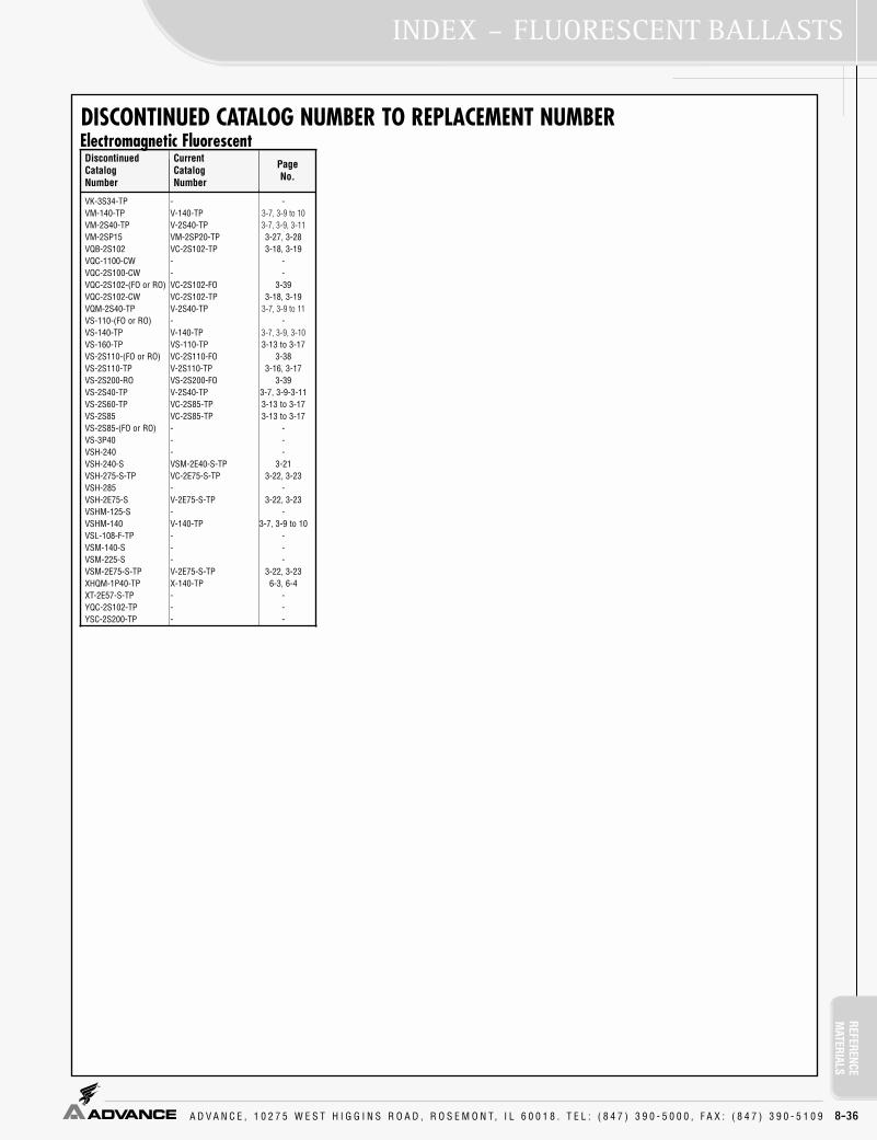
REFERENCEM
ATERIALSINDEX – FLUORESCENT BALLASTS
A D V A N C E , 1 0 2 7 5 W E S T H I G G I N S R O A D , R O S E M O N T, I L 6 0 0 1 8 . T E L : ( 8 4 7 ) 3 9 0 - 5 0 0 0 , F A X : ( 8 4 7 ) 3 9 0 - 5 1 0 9 8-36
Discontinued CatalogNumber
CurrentCatalogNumber
PageNo.
DISCONTINUED CATALOG NUMBER TO REPLACEMENT NUMBER
VK-3S34-TP - -VM-140-TP V-140-TP 3-7, 3-9 to 10VM-2S40-TP V-2S40-TP 3-7, 3-9, 3-11VM-2SP15 VM-2SP20-TP 3-27, 3-28VQB-2S102 VC-2S102-TP 3-18, 3-19VQC-1100-CW - -VQC-2S100-CW - -VQC-2S102-(FO or RO) VC-2S102-FO 3-39VQC-2S102-CW VC-2S102-TP 3-18, 3-19VQM-2S40-TP V-2S40-TP 3-7, 3-9 to 11VS-110-(FO or RO) - -VS-140-TP V-140-TP 3-7, 3-9, 3-10VS-160-TP VS-110-TP 3-13 to 3-17VS-2S110-(FO or RO) VC-2S110-FO 3-38VS-2S110-TP V-2S110-TP 3-16, 3-17VS-2S200-RO VS-2S200-FO 3-39VS-2S40-TP V-2S40-TP 3-7, 3-9-3-11VS-2S60-TP VC-2S85-TP 3-13 to 3-17VS-2S85 VC-2S85-TP 3-13 to 3-17VS-2S85-(FO or RO) - -VS-3P40 - -VSH-240 - -VSH-240-S VSM-2E40-S-TP 3-21VSH-275-S-TP VC-2E75-S-TP 3-22, 3-23VSH-285 - -VSH-2E75-S V-2E75-S-TP 3-22, 3-23VSHM-125-S - -VSHM-140 V-140-TP 3-7, 3-9 to 10VSL-108-F-TP - -VSM-140-S - -VSM-225-S - -VSM-2E75-S-TP V-2E75-S-TP 3-22, 3-23XHQM-1P40-TP X-140-TP 6-3, 6-4XT-2E57-S-TP - -YQC-2S102-TP - -YSC-2S200-TP - -
Electromagnetic Fluorescent

REFE
RENC
EM
ATER
IALS
A D V A N C E , 1 0 2 7 5 W E S T H I G G I N S R O A D , R O S E M O N T, I L 6 0 0 1 8 . T E L : ( 8 4 7 ) 3 9 0 - 5 0 0 0 , F A X : ( 8 4 7 ) 3 9 0 - 5 1 0 9
INDEX – FLUORESCENT BALLASTS
8-37
Discontinued CatalogNumber
SuggestedReplacementCatalog Number
PageNo.
Discontinued CatalogNumber
SuggestedReplacementCatalog Number
PageNo.
Discontinued CatalogNumber
SuggestedReplacementCatalog Number
PageNo.
DISCONTINUED CATALOG NUMBER TO REPLACEMENT NUMBER
GDC-132-TP …. ….GDC-140-TP …. ….GDC-2S32-TP …. ….GDC-2S40-TP …. ….GIC-132-TP GEL-2P32-LW 1-45, 49, 54, 55, 59GIC-140-TP …. ….GIC-2S32-TP GEL-2P32-SC 1-45, 48, 49, 54,
55, 58, 59GIC-2S40-TP GEL-2S40-RH-TP 1-66, 1-67IZT-1T42-M2-BS* IZT-2S26-M5-BS 2-12IZT-1T42-M2-LD* IZT-2S26-M5-LD 2-12IZT-2Q26-M2-BS* IZT-2S26-M5-BS 2-12IZT-2Q26-M2-LD* IZT-2S26-M5-LD 2-12IZT-2T42-M3-BS* IZT-2T42-M5-BS 2-12IZT-2T42-M3-LD* IZT-2T42-M5-LD 2-12RCN-132-MC ICN-132-MC 1-41, 1-44, 1-54, 1-58RCN-1P32 ICN-1P32-SC 1-44, 1-48, 1-54, 1-58RCN-1P32-SC ICN-1P32-SC 1-44, 1-48, 1-54, 1-58RCN-1S28* ICN-2S28 1-41RCN-1S40-SC REL-1S40-SC 1-66, 1-67RCN-2M32-MC ICN-2M32-MC 1-41, 45, 49, 55, 59RCN-2P32 ICN-2P32-SC 1-44, 45, 48, 49,
54, 55, 58, 1-59, 62RCN-2P32-LW ICN-2P32-LW-SC 1-44, 45, 48, 49,
54, 55, 59, 62RCN-2P32-SC ICN-2P32-SC 1-44, 45, 48, 49,
54, 1-55, 58, 59, 62RCN-2P54-SC ICN-2S54 1-34, 36, 37,
42, 43, 6-6RCN-2S28* ICN-2S28 1-41RCN-2S32-LW ICN-2P32-LW-SC 1-44, 45, 48, 49,
54, 55, 59, 62RCN-2S40 REL-2S40-SC 1-66, 1-67RCN-2S40-SC REL-2S40-SC 1-66, 1-67RCN-2S86 ICN-2S86 1-65RCN-3P32 ICN-3P32-SC 1-45, 46, 49, 50,
55, 56, 59, 60, 62RCN-3P32-LW-SC ICN-3P32-LW-SC 1-45, 46, 49, 50,
55, 56, 59, 60, 62RCN-3P32-SC ICN-3P32-SC 1-45, 46, 49, 50,
55, 56, 59, 60, 62RCN-4P32 ICN-4P32-SC 1-46, 47, 50, 51,
56, 57, 60, 61, 63RCN-4P32-LW-SC ICN-4P32-LW-SC 1-46, 47, 50, 51,
56, 57, 60, 61, 63RCN-4P32-SC ICN-4P32-SC 1-46, 47, 50, 51,
56, 57, 60, 61, 63RDC-132-TP IZT-132-SC 2-15, 2-16 RDC-140-TP …. ….RDC-2BS40-TP IZT-2TTS40-SC 2-13RDC-2S32-TP IZT-2S32-SC 2-15, 2-16RDC-2S40-TP …. ….RDC-3S32-TP IZT-3S32-SC 2-15, 2-16RDC-3S40-TP …. ….REL-1P32-RH-TP REL-1P32-SC 1-44, 48, 54, 58REL-1S32-RH-TP RCN-1S32-SC 1-44, 48, 54, 58REL-1S40-RH-TP REL-1S40-SC 1-66, 1-67REL-1S40-TP REL-1S40-SC 1-66, 1-67REL-1T32 ICF-2S26-H1-LD 1-28, 31, 32, 34, 38REL-1T42 ICF-2S26-H1-LD 1-28, 31, 32, 34, 38REL-2P32-HL-RH-TP REL-2P32-HL-SC 1-45, 48, 49, 54,
55, 58, 59, 62REL-2P32-LW-RH-TP REL-2P32-LW-SC 1-45, 49, 54, 55,
58, 59, 62REL-2P32-RH-TP REL-2P32-SC 1-45, 48, 49, 54,
55, 58, 59, 6-6REL-2P50-SC …. ….REL-2P59-HL …. ….REL-2P75-S-RH-TP REL-2P60-S 1-68REL-2P75-S-TP REL-2P60-S 1-68REL-2Q18 ICF-2S18-H1-LD 1-27, 30, 38REL-2Q26 ICF-2S26-H1-LD 1-28, 31, 32, 34, 38REL-2S32-LW-RH-TP REL-2P32-LW-SC 1-45, 49, 54, 55,
58, 59, 62REL-2S32-RH-TP RCN-2S32-SC 1-45, 49, 55, 59REL-2S40-RH-TP REL-2S40-SC 1-66, 1-67REL-2S40-TP REL-2S40-SC 1-66, 1-67REL-3P32-HL REL-3P32-HL-SC 1-46, 49, 50, 55,
56, 59, 60, 62REL-3P32-LW-RH-TP REL-3P32-LW-SC 1-46, 49, 50, 55,
56, 59, 60, 62REL-3P32-RH-TP REL-3P32-SC 1-46, 49, 50, 55,
56, 59, 60, 62, 6-6REL-3P32-TP REL-3P32-SC 1-46, 49, 50, 55,
56, 59, 60, 62, 6-6REL-3S32-LW-RH-TP REL-3P32-LW-SC 1-46, 49, 50, 55,
56, 59, 60, 62REL-3S32-RH-TP RCN-3S32-SC 1-46, 50, 56, 60REL-3S40-TP REL-3S40-RH-TP 1-66, 1-67REL-4P32 REL-4P32-SC 1-47, 50, 51, 56,
57, 60, 61, 63, 6-6REL-4P32-2LS - -REL-4P32-LW-RH-TP REL-4P32-LW-SC 1-46, 47, 50, 51,
56, 57, 60, 61, 63REL-4P32-RH-TP REL-4P32-SC 1-47, 50, 51, 56,
57, 60, 61, 63, 6-6REL-4P32-TP REL-4P32-SC 1-47, 50, 51, 56,
57, 60, 61, 63, 6-6REZ-132 REZ-132-SC 2-10REZ-1T32 REZ-1T42-M2-LD-K 2-7REZ-1T42 REZ-1T42-M2-LD-K 2-7REZ-1TTS40 REZ-1TTS40-SC 2-8REZ-2Q26 REZ-2Q26-M2-LD-K 2-7REZ-2S32 REZ-2S32-SC 2-10REZ-2TTS40 REZ-2TTS40-SC 2-8REZ-3S32 REZ-3S32-SC 2-10REZ-C1200-A …. ….REZ-C500-1 …. ….RIC-132 IIC-132-SC 1-44, 48, 54, 58RIC-132-TP IIC-132-SC 1-44, 48, 54, 58RIC-140-TP REL-1S40-SC 1-66, 1-67RIC-2S32 IIC-2S32-SC 1-45, 49, 55, 59RIC-2S32-TP IIC-2S32-SC 1-45, 49, 55, 59RIC-2S40-TP REL-2S40-SC 1-66, 1-67RIC-3S32 IIC-2S32-SC 1-45, 49, 55, 59RIC-3S32-TP IIC-2S32-SC 1-45, 49, 55, 59RIC-3S40-TP REL-3S40-RH-TP 1-66, 1-67RZT-132 IZT-132-SC 2-15, 2-16 RZT-1TTS40 RZT-1TTS40-SC 2-8RZT-2S32 IZT-2S32-SC 2-15, 2-16RZT-2TTS40 IZT-2TTS40-SC 2-13RZT-3S32* IZT-3S32-SC 2-15, 2-16VCN-132-MC ICN-132-MC 1-41, 44, 54, 58VCN-1P32 ICN-1P32-SC 1-44, 48, 54, 58VCN-1P32-SC ICN-1P32-SC 1-44, 48, 54, 58VCN-1S28* ICN-2S28 1-41VCN-1S40-SC VEL-1S40-SC 1-66, 1-67VCN-2M32-MC ICN-2M32-MC 1-41, 45, 49, 55, 59VCN-2P32 ICN-2P32-SC 1-44, 45, 48, 49,
54, 55, 58, 59, 62VCN-2P32-LW ICN-2P32-LW-SC 1-44, 45, 48, 49,
54, 55, 58, 59, 62VCN-2P32-SC ICN-2P32-SC 1-44, 45, 48, 49,
54, 55, 58, 59, 62VCN-2P54-SC ICN-2S54 1-34, 36, 37,
42, 43, 6-6VCN-2S28* ICN-2S28 1-41VCN-2S32-LW ICN-2P32-LW-SC 1-44, 45, 48, 49,
54, 55, 58, 59, 62VCN-2S40 REL-2S40-SC 1-66, 1-67VCN-2S40-SC VEL-2S40-SC 1-66, 1-67VCN-2S86 ICN-2S86 1-65VCN-3P32 ICN-3P32-SC 1-45, 46, 49, 50,
55, 56, 59, 60, 62VCN-3P32-LW-SC ICN-3P32-LW-SC 1-45, 46, 49, 50,
55, 56, 59, 60, 62VCN-3P32-SC ICN-3P32-SC 1-45, 46, 49, 50,
55, 56, 59, 60, 62VCN-4P32 ICN-4P32-SC 1-46, 47, 50, 51,
56, 57, 60, 61, 63VCN-4P32 VCN-4P32-SC 1-47, 51, 57, 61VCN-4P32-LW-SC ICN-4P32-LW-SC 1-46, 47, 50, 51,
56, 57, 60, 61, 63VCN-4P32-SC ICN-4P32-SC 1-46, 47, 50, 51,
56, 57, 60, 61, 63VDC-132-TP IZT-132-SC 2-15, 2-16VDC-140-TP …. ….VDC-2BS40-TP IZT2TTS40 2-13VDC-2S32-TP IZT-2S32-SC 2-15, 2-16VDC2S40-TP …. ….VDC-3S32-TP IZT-3S32 2-15, 2-16VDC-3S40-TP …. ….VEL-175-S-TP VEL-2P75-S 1-68VEL-1P32-RH-TP VEL-1P32-SC 1-44, 48, 54, 58VEL-1S32-RH-TP VCN-1S32-SC 1-44, 48, 54, 58
GK-2S110-TP … ….RK-134-TP …. ….RK-2S110-TP …. ….RK-2S40-TP RK-2S34-TP 1-67RK-3S34-TP …. ….VK-134-TP …. ….VK-2S40-TP VK-2S34-TP 1-67
* These ballasts will be phased out during 2004 and their replacements will be available accordingly.
Note: In some cases, replacement may have different dimensions, specifications, starting method, lampssupported or wiring configurations. Technical specifications of the replacement should be evaluated forintended application.
High Frequency Electronic Fluorescent High Frequency Electronic Fluorescent
Low Frequency Electronic Fluorescent
High Frequency Electronic FluorescentDiscontinued CatalogNumber
SuggestedReplacementCatalog Number
PageNo.
VEL-1S40-RH-TP VEL-1S40-SC 1-66, 1-67VEL-1S40-TP VEL-1S40-SC 1-66, 1-67VEL-1T32 ICF-2S26-H1-LD 1-28, 31, 32, 34, 38VEL-1T42 ICF-2S26-H1-LD 1-28, 31, 32, 34, 38VEL-2E75-S-TP VEL-2P75-S 1-68VEL-2P32-HL-RH-TP VEL-2P32-HL-SC 1-45, 48, 49, 54,
55, 58, 59, 62VEL-2P32-LW-RH-TP VEL-2P32-LW-SC 1-45, 49, 54, 55,
58, 59, 62VEL-2P32-RH-TP VEL-2P32-SC 1-45, 48, 49, 54,
55, 58, 59, VEL-2P50-SC …. ….VEL-2P59-HL - -VEL-2Q18 ICF-2S18-H1-LD 1-27, 1-30, 1-38VEL-2Q26 ICF-2S26-H1-LD 1-28, 31, 32, 34, 38VEL-2S32-LW-RH-TP VEL-2P32-LW.SC 1-45, 49, 54, 55,
58, 59, 62VEL-2S32-RH-TP VCN-2S32-SC 1-45, 1-49, 1-55
1-59VEL-2S40-RH-TP VEL-2S40-SC 1-66, 1-67VEL-2S40-TP VEL-2S40-SC 1-66, 1-67VEL-3P32-HL VEL-3P32-HL-SC 1-46, 49, 50, 55,
56, 59, 60, 62VEL-3P32-LW-RH-TP VEL-3P32-LW-SC 1-45, 46, 49, 50,
55, 56, 59, 60, 62VEL-3P32-RH-TP VEL-3P32-SC 1-46, 49, 50, 55,
56, 59, 60, 62VEL-3P32-TP VEL-3P32-SC 1-46, 49, 50, 55,
56, 59, 60, 62VEL-3S32-LW-RH-TP VEL-3P32-LW-SC 1-45, 46, 49, 50,
55, 56, 59, 60, 62VEL-3S32-RH-TP VCN-3S32-SC 1-46, 50, 56, 60VEL-3S40-TP VEL-3S40-RH-TP 1-66, 1-67VEL-4P32-2LS - -VEL-4P32-LW-RH-TP VEL-4P32-LW-SC 1-46, 47, 50, 51,
56, 57, 60, 61, 63VEL-4P32-RH-TP VEL-4P32-SC 1-47, 50, 51, 56,
57, 60, 61, 63VEL-4P32-TP VEL-4P32-SC 1-47, 50, 51, 56,
57, 60, 61, 63VEZ-132 VEZ-132-SC 2-10VEZ-1T32 VEZ-1T42-M2-LD-K 2-7VEZ-1T42 VEZ-1T42-M2-LD-K 2-7VEZ-1TTS40 VEZ-1TTS40-SC 2-8VEZ-2Q26 VEZ-2Q26-M2-LD-K 2-7VEZ-2S32 VEZ-2S32-SC 2-10VEZ-2TTS40 VEZ-2TTS40-SC 2-8VEZ-3S32 VEZ-2S32-SC 2-10VEZ-C1200-A …. ….VEZ-C500-1 …. ….VIC-132 IIC-132-SC 1-44, 48, 54, 58VIC-132-TP IIC-132-SC 1-44, 48, 54, 58VIC-140-TP VEL-1S40-SC 1-66, 1-67VIC-2S32 IIC-2S32-SC 1-45, 49, 55, 59VIC-2S32-TP IIC-2S32-SC 1-45, 49, 55, 59VIC-2S40-TP VEL-2S40-SC 1-66, 1-67VIC-3S32 IIC-2S32-SC 1-45, 49, 55, 59VIC-3S32-TP IIC-2S32-SC 1-45, 49, 55, 59VIC-3S40-TP VEL-3S40-RH-TP 1-66, 1-67VZT-132 IZT-132-SC 2-15, 2-16 VZT-1TTS40-SC VZT-1TTS40-SC 2-8VZT-2S32 IZT-2S32-SC 2-15, 2-16VZT-2TTS40-SC IZT-2TTS40-SC 2-13VZT-3S32* IZT-3S32-SC 2-15, 2-16VZT-4S32-4 IZT-4S32 2-15, 2-16VZT-4S32-8 IZT-4S32 2-15, 2-16
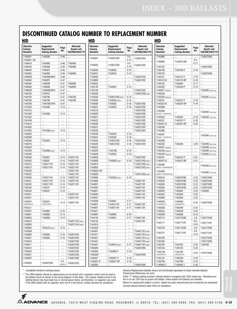
REFERENCEM
ATERIALSINDEX – HID BALLASTS
A D V A N C E , 1 0 2 7 5 W E S T H I G G I N S R O A D , R O S E M O N T, I L 6 0 0 1 8 . T E L : ( 8 4 7 ) 3 9 0 - 5 0 0 0 , F A X : ( 8 4 7 ) 3 9 0 - 5 1 0 9 8-38
DISCONTINUED CATALOG NUMBER TO REPLACEMENT NUMBER
ObsoleteCatalogNumbers
SuggestedReplacementCatalog Number
PageNo.
AlternateQuadri-volt
120/208/240/277V
ObsoleteCatalogNumbers
SuggestedReplacementCatalog Number
PageNo.
AlternateQuadri-volt
120/208/240/277V
ObsoleteCatalogNumbers
SuggestedReplacementCatalog Number
PageNo.
AlternateQuadri-volt
120/208/240/277V
71A0201 71A0280 5-46 ….71A0401-791 .... .... ....71A0410 71A0490 5-46 71A049071A0430 71A0490 5-46 71A049071A0440 71A04F0 5-46 ….71A0450 71A0490 5-46 71A049071A04D0 71A0490/04F0 5-46 ….71A0540 71A05F0 5-47 ….71A0550 71A0590 5-47 71A059071A0560 71A0590 5-47 71A059071A05D0 71A0590/05F0 5-47 ….71A0740 71A07F0 5-47 ….71A0750 71A0790 5-47 71A079071A0760 71A0790 5-47 71A079071A07D0 71A0790/07F0 5-47 ….71A1500 71A1580 5-14 ....71A1510 .... .... ....71A1530 71A1580 5-14 ....71A1540 .... .... ....71A15R0 .... .... ....71A1810 .... .... ....71A1820 .... .... ....71A1830 71A1580(CWA)** 5-14 ....71A2020 .... .... ....71A20R0 .... .... ....71A2300 71A2303 5-14 ....71A2310 .... .... ....71A2320 .... .... ....71A2330 71A2080(CWA)** 5-14 ....71A2340 .... .... ....71A2500 71A2501 5-14 71A2571/9171A2502 71A2501 5-14 71A2571/9171A2510 71A2571/91 5-14 71A2571/9171A2512 71A2571/91 5-14 71A2571/9171A2520 .... .... 71A2571/9171A2522 .... .... 71A2571/9171A2530 71A2571/91 5-14 71A2571/9171A2531 71A2571/91 5-14 71A2571/9171A2532 71A2571/91 5-14 71A2571/9171A2540 71A2541 5-14 ....71A2542 71A2541 5-14 ....71A2551 .... .... 71A2571/9171A2561 .... .... 71A2571/91
71A25D1 71A25A1 5-14 71A2571/91(120/240/347V) (120/277/347V)
71A25J1 .... .... ....71A25R1 71A25N1 5-15 ....71A2801 71A2800 5-14 ....71A2803 71A2800 5-14 ....71A2810 .... .... 71A2571/91(CWA)**
71A2820 .... .... 71A2571/91(CWA)**
71A2840 71A2541(CWA)** 5-14 ....71A29G0 .... .... ....71A3000 71A3002 5-15 71A3072/9271A3001 71A3002 5-15 71A3072/9271A3010 .... .... 71A3072/9271A3011 .... .... 71A3072/9271A3012 .... .... 71A3072/9271A3020 .... .... 71A3072/9271A3021 .... .... 71A3072/9271A3022 .... .... 71A3072/92
71A3030 71A3072/925-5,5-15 71A3072/92
71A3031 71A3072/925-5,5-15 71A3072/92
71A3032 71A3072/925-5,5-15 71A3072/92
71A3040 71A3042 5-15 ....71A3041 71A3042 5-15 ....71A3052 .... .... 71A3072/9271A3062 .... .... 71A3072/9271A30J2 .... .... ....71A3140 71A3042 5-15 ....71A3150 .... .... 71A3072/9271A3320 .... .... 71A3072/92(CWA)**
71A3330 71A3072/92(CWA)** 5-15 ....71A3340 71A3042(CWA)** 5-15 ....71A3500 71A3502 5-16 71A3572/9271A3501 71A3502 5-16 71A3572/9271A3510 .... .... 71A3572/9271A3520 .... .... 71A3572/9271A3521 .... .... 71A3572/9271A3522 .... .... 71A3572/9271A3530 .... .... 71A3572/9271A3531 .... .... 71A3572/9271A3532 .... .... 71A3572/9271A3540 71A3542 5-16 ....71A3541 71A3542 5-16 ....71A3552 71A3572/92 5-16 71A3572/9271A3562 71A3572/92 5-16 71A3572/9271A35J2 .... .... ....71A35R2 71A57N0 6-16 ....71A3640 71A3542 5-16 ....71A3650 .... .... 71A3572/9271A3800 71A3502(CWA)** 5-16 71A3572/92(CWA)**
71A3810 .... .... 71A3572/92(CWA)**
71A3820 .... .... 71A3572/92(CWA)**
71A3825-791 .... .... ....71A3830 .... .... 71A3572/92(CWA)**
71A3840 71A3542(CWA)** 5-16 ....71A4000 .... .... 71A4071/9171A4001 .... .... 71A4071/9171A4020 .... .... 71A4071/9171A4021 .... .... 71A4071/9171A4030 .... .... 71A4071/9171A4031 .... .... 71A4071/9171A4040 71A4041 5-17 ....71A4051 71A4071/91 5-17 71A4071/9171A4061 71A4071/91 5-17 71A4071/9171A40J1 .... .... ....71A40R1 71A60N1 6-16 ....71A4142 71A4041 5-17 71A4071/9171A4152 .... .... 71A4071/9171A4310 .... .... ....71A4320 .... .... ....71A4401 .... .... 71A4071/91(CWA)**
71A4411 .... .... 71A4071/91(CWA)**
71A4421 .... .... 71A4071/91(CWA)**
71A4431 .... .... 71A4071/91(CWA)**
71A4441 71A4041(CWA)** 5-17 71A4071/91(CWA)**
71A5000 .... .... 71A5070/9071A5005 71A5005-P 5-18 ....71A5030* .... .... 71A5070/9071A5037 71A5037-P 5-18 ....71A5037-B 71A5037-BP 5-18 ....71A5050 .... .... 71A5070/90
71A5060 .... .... 71A5070/90
71A5090 71A5070-0015-5,5-17
71A5102 .... .... 71A5070/9071A5105 71A5105-P 5-18 ....71A5122 .... .... 71A5070/9071A5137 71A5137-P 5-18 ....71A5137-B 71A5137-BP 5-18 ....71A5142 71A5040 5-17 ....71A5205 71A5205-P 5-19 ....71A5227 (Reactor) .... .... 71A5292 (3x4 Core)
71A5228 .... .... ....71A5229 (Reactor) .... .... 71A5292 (3x4 Core)
71A5237 71A5237-P 5-19 ....71A5237-B 71A5237-BP 5-19 ....71A5288 .... .... ....
71A5289 .... .... 71A5292 (3x4 Core)(Reactor + Transformer)
71A52C2 71A52A2 5-19 71A5292 (3x4 Core)
71A5337 71A5337-P 5-20 ....71A5337-B 71A5337-BP 5-20 ....71A5338 .... .... ....71A5386 .... .... ....
71A5387 .... .... 71A5390 (3x4 Core)(Reactor + Transformer)
71A5388 .... .... ....71A53C0 71A53A0 5-20 71A5390 (3x4 Core)
71A5427 (Reactor) .... .... 71A5490 (3x4 Core)
71A5428 (Reactor) .... .... 71A5490 (3x4 Core)
71A5429 (Reactor) .... .... 71A5492 (3x4 Core)
71A5437 71A5437-P 5-21 ....71A5437-B 71A5437-BP 5-21 ....
71A5488 .... .... 71A5490 (3x4 Core)(Reactor + Autotransformer)
71A5489 .... .... 71A5492 (3x4 Core)(Reactor + Autotransformer)
71A5510 71A5570/90 5-22 71A5570/9071A5520 71A5570/90 5-22 71A5570/9071A5550 71A5570/90 5-22 71A5570/9071A5560 71A5570/90 5-22 71A5570/9071A5592 71A5593 5-22 71A559371A55A2 71A55A3 5-22 ....71A55B0 71A55A0 5-22 ....
71A55D0 71A55A0 5-22 71A5570/90(120/240/347V) (120/240/347V)
71A55G0 71A55H0 5-22 ....71A55J0 71A55H0 5-22 ....71A55R0 71A55N0 6-16 ....71A5710 71A5770/90 5-6 71A5770/90
71A5711 71A5771/915-6,5-24 71A5771/91
71A5720 71A5770/90 5-6 71A5770/90
71A5721 71A5771/915-6,5-24 71A5771/91
71A5750 .... .... 71A5770/9071A5760 .... .... 71A5770/9071A5793 71A5792 5-25 71A579271A57A3 71A57A2 5-25 ....
71A57D0 71A57A0 5-24 71A5770/90(120/240/347V) (120/240/347V)
71A57J0 71A55H0 5-22 ....71A57R0 71A57N0 6-16 ....71A5843-T 71A5842-T 5-26 ....
Advance Replacement ballasts shown are functionally equivalent to listed obsolete ballasts.Dimensional differences can exist.Suffix “T” ballast catalog numbers indicate ballast is equipped with 120V output tap. Standard prac-tice is to use 120V tap on quadri-volt ballast, where quadri-volt ballasts are available.Where no replacement ballast is shown, ballast has been discontinued and inventories are exhausted.Consult nearest Advance sales office for assistance.
* Availability limited to existing stocks.
** The CWA ballasts offered as replacements are furnished with a capacitor which must be used inthe ballast circuit as shown in the wiring diagram in this Atlas. The original ballast circuit in thelighting fixture may have been low or normal power factor, and therefore, no capacitor was used.If the CWA ballast with its capacitor does not fit in the fixture, contact Advance for assistance.
HID HID HID

REFE
RENC
EM
ATER
IALS
A D V A N C E , 1 0 2 7 5 W E S T H I G G I N S R O A D , R O S E M O N T, I L 6 0 0 1 8 . T E L : ( 8 4 7 ) 3 9 0 - 5 0 0 0 , F A X : ( 8 4 7 ) 3 9 0 - 5 1 0 9
INDEX – HID BALLASTS
8-39
DISCONTINUED CATALOG NUMBER TO REPLACEMENT NUMBER
ObsoleteCatalogNumbers
SuggestedReplacementCatalog Number
PageNo.
AlternateQuadri-volt
120/208/240/277V
ObsoleteCatalogNumbers
SuggestedReplacementCatalog Number
PageNo.
AlternateQuadri-volt
120/208/240/277V
ObsoleteCatalogNumbers
SuggestedReplacementCatalog Number
PageNo.
AlternateQuadri-volt
120/208/240/277V
71A5893 71A5892 5-26 71A589271A58A3 71A58A2 5-26 ....71A58N3 71A58N2 6-16 ....71A5942-T 71A5943-T 5-26 ....71A5992 71A5993 5-26 71A599371A59A2 71A59A3 5-26 ....71A59N2 71A59N3 6-16 ....71A6000 71A6001 5-27 71A6071/91
71A6010 71A6071/915-6,5-27 71A6071/91
71A6011 71A6071/915-6,5-27 71A6071/91
71A6020 71A6021 5-26 71A6071/91
71A6021 71A6071/915-6,5-27 71A6071/91
71A6030 71A6031 5-27 71A6071/9171A6040 71A6041 5-27 71A6071/9171A6043-T 71A6042-T 5-28 ....
71A6061 71A6071/915-6,5-27 71A6071/91
71A6084(120/277V) 71A6004(120V) 5-26 71A6034(277V)
71A6093 71A6092 5-28 71A609271A60A3 71A60A2 5-28 ....71A60B1 71A60A1(120/277/347V) 5-27 ....
71A60D1 71A60A1 5-27 71A6071/91(120/240/347V) (120/277/347V)
71A60J1 71A60H1 5-27 ....71A60N3 71A60N2 6-16 ....71A60R1 71A60N1 6-16 ....71A6300 (Series) 71A6382(ILO) 5-28 ....71A6310 (Series) .... .... ....71A6320 (Series) .... .... ....71A6330 (Series) 71A6382-001D(ILO) 5-6 ....71A6340 (Series) 71A6382-001D(ILO) 5-6 ....71A6342 71A6342-001D 5-6 ....71A6352 (120/240V) 71A6382-001D(120V) 5-6 ....71A6382 71A6382-001D 5-6 ....71A63J2 .... .... ....71A6500 71A6502 5-30 71A6572/9271A6501 71A6502 5-30 71A6572/9271A6510 71A6572/92 5-30 71A6572/9271A6511 71A6572/92 5-30 71A6572/9271A6512 71A6572/92 5-30 71A6572/9271A6520 71A6572/92 5-30 71A6572/9271A6521 71A6572/92 5-30 71A6572/9271A6522 71A6572/92 5-30 71A6572/9271A6530 71A6532 5-30 71A6572/9271A6531 71A6532 5-30 71A6572/9271A6540 71A6542 5-30 ....71A6541 71A6542 5-30 ....71A6551 71A6572/92 5-30 71A6572/9271A6561 71A6572/92 5-30 71A6572/9271A6571 71A6572 5-30 71A6572/9271A65B2 71A65A2(120/277/347V) 5-30 ....71A65D2(120/240/347V) 71A65A2 5-30 ....
71A65E3 71A6593 5-29 71A6593(120/240/347V) (120/240/347V)
71A65F3 71A65F3-T 5-29 ....(277/347/480V) (347/480V/120T)
71A65M6 .... .... ....71A65R2 71A65N2 6-16 ....71A6700 71A6702 5-31 71A6772/92
71A6701 71A6702 5-31 71A6772/92
71A6710 71A6772/925-6,5-31 71A6772/92
71A6711 71A6772/925-6,5-31 71A6772/92
71A6712 71A6772/925-6,5-31 71A6772/92
71A6720 71A6722/92 5-31 71A6772/9271A6721 71A6722/92 5-31 71A6772/9271A6722 71A6722/92 5-31 71A6772/9271A6730 71A6732 5-31 71A6772/9271A6731 71A6732 5-31 71A6772/9271A6740 71A6742 5-31 ....
71A6771 71A67725-6,5-31 71A6772/92
71A6791 71A6792 5-31 71A6772/92
71A67D2 71A67A2 5-31 71A6772/92(120/240/347V) (120/277/347V)
71A68J0 .... .... ....71A7900 71A7950 5-35 ....71A7910* .... .... ....71A7920 71A7950 5-35 ....71A7956 71A79E6(120/208/240V) 5-35 ....71A7960(240/480V) 71A7950(120/240V) 5-35 71A7940*(480V)
71A79D1 71A79A1 5-34 71A7971/91(120/240/347V) (120/277/347)
71A8000 71A8050/80 5-37 ....71A8030 71A8080 5-37 ....71A8056 71A80E6 (120/277/347) 5-37 ....71A8060(240/480V) .... .... 71A8040(480V)
71A80D1 71A80A1 5-36 71A8071/91(120/240/347V) (120/277/347V)
71A80R1 71A79N1,71A80N1 6-17 ....71A8106* .... .... 71A8176/9671A8111 .... .... 71A8176/9671A8116* .... .... 71A8176/9671A8130 71A8180 5-39 ....
71A8131 71A8176/965-7,5-38 71A8176/96
71A8136 71A8176/965-7,5-38 71A8176/96
71A8141 .... .... ....71A8151 .... .... 71A8176/9671A8156 71A81E6(120/208/240V) 5-39 ....
71A81D2 71A81A2 5-38 71A8172/92(120/240/347V) (120/277/347V)
71A81R2 71A81N2 6-17 ....71A8211 71A8271/91 5-41 71A8271/9171A8221 71A8271/91 5-41 71A8271/9171A8230 71A8280 5-41 ....71A8250(120/240V) .... .... 71A8220(240V)
71A8256 71A82E6(120/208/240V) 5-41 ....71A8260(240/480V) .... .... 71A8240(480V)
71A8294 71A8280(120/277V) 5-41 71A8220(240V)(120/208/240/277V) 71A8210(208V)
71A82B1 71A82A1(120/277/347V) 5-41 ....
71A82D1 71A82A1 5-41 71A8271/91(120/240/347V) (120/277/347V)
71A82R1 71A82N1 6-17 ....71A8311 .... .... 71A8371/9171A8321 .... .... 71A8371/9171A8331 .... .... 71A8371/91
71A8401 71A8403 5-43 71A8473/9371A8402 71A8403 5-43 71A8473/9371A8411 71A8473/93 5-43 71A8473/9371A8412 71A8473/93 5-43 71A8473/9371A8413 71A8473/93 5-43 71A8473/9371A8420 71A8450 5-43 ....71A8421 71A8473/93 5-43 71A8473/9371A8422 71A8473/93 5-43 71A8473/9371A8423 71A8473/93 5-43 71A8473/9371A8430 71A8480 5-43 ....71A8431 71A8433 5-43 71A8473/9371A8432 71A8433 5-43 71A8473/9371A8441 71A8443 5-43 ....71A8442 71A8443 5-43 ....71A8456 71A84E6(120/208/240V) 5-43 ....71A8471 .... .... 71A8473/9371A8472 .... .... 71A8473/9371A8482 .... .... 71A8473/9371A8484 71A8480 5-43 ....71A8491 .... .... 71A8473/9371A8492 .... .... 71A8473/93
71A84D3 71A84A3 5-43 71A8473/93(120/240/347V) (120/277/347V)
71A84R2 71A84N3 6-17 ....71A8540 71A85F5 5-44 ....
71A8590 71A85E5 5-44 71A85F5(120/208/240/277V) (120/208/240V) (277/347/480)
71A85A3 .... .... ....71A8741 71A8743 5-45 ....71A8771 71A8773/93 5-45 71A8773/9371A8791 71A8773/93 5-45 71A8773/93
71A87D3 71A87A3 5-45 71A8773/93(120/240/347V) (120/277/347V)
71A8900 .... .... 71A8970/9071A8930 .... .... 71A8970/9071A8931 .... .... 71A899171A8984(120/277V) 71A8954(120V) 5-40 71A8970/90 (CWA)
71A9068 .... .... 71A4071/9171A9073 .... .... 71A5070/9071A9074 71A5040 5-18 ....71A9082 .... .... 71A4071/9171A9114 .... .... ....
71A9115 71A40R15-9,5-17 ....
71A9116 71A65N2 6-16 ....71A9124 .... .... 71A4071/9171A9127 .... .... 71A5070/9071A9135 .... .... 71A3072/9271A9136 .... .... 71A3072/9271A9137 .... .... 71A3072/92
71A9138 71A3072/925-5,5-15 71A3072/92
71A9139 71A3042 5-15 ....71A9189 71A0590 5-47 ....71A9192 71A0490 5-46 ....71A9209 71A5580 5-22 71A5570/9071A9212 71A6382-001D 5-6 ....71A9240 .... .... 71A3572/9271A9242 .... .... 71A5570/9071A9243 71A5540 5-22 ....71A9263 .... .... 71A3572/9271A9278 71A25N1 6-15 ....
* Availability limited to existing stocks.
** The CWA ballasts offered as replacements are furnished with a capacitor which must be used inthe ballast circuit as shown in the wiring diagram in this Atlas. The original ballast circuit in thelighting fixture may have been low or normal power factor, and therefore, no capacitor was used.If the CWA ballast with its capacitor does not fit in the fixture, contact Advance for assistance.
Advance Replacement ballasts shown are functionally equivalent to listed obsolete ballasts. Dimensionaldifferences can exist.Suffix “T” ballast catalog numbers indicate ballast is equipped with 120V output tap. Standard practiceis to use 120V tap on quadri-volt ballast, where quadri-volt ballasts are available.Where no replacement ballast is shown, ballast has been discontinued and inventories are exhausted.Consult nearest Advance sales office for assistance.
HID HID HID

REFERENCEM
ATERIALSINDEX – HID BALLASTS
A D V A N C E , 1 0 2 7 5 W E S T H I G G I N S R O A D , R O S E M O N T, I L 6 0 0 1 8 . T E L : ( 8 4 7 ) 3 9 0 - 5 0 0 0 , F A X : ( 8 4 7 ) 3 9 0 - 5 1 0 9 8-40
DISCONTINUED CATALOG NUMBER TO REPLACEMENT NUMBER
ObsoleteCatalogNumbers
SuggestedReplacementCatalog Number
PageNo.
AlternateQuadri-volt
120/208/240/277V
ObsoleteCatalogNumbers
SuggestedReplacementCatalog Number
PageNo.
AlternateQuadri-volt
120/208/240/277V
ObsoleteCatalogNumbers
SuggestedReplacementCatalog Number
PageNo.
AlternateQuadri-volt
120/208/240/277V
71A9279 71A35R25-11,5-16 ....
71A9280 71A55N0 6-16 71A928171A9282 71A65N2 6-16 ....71A9301 71A07F0 5-47 ....71A9302 .... .... 71A6071/9171A9303 .... .... 71A6071/9171A9305 .... .... 71A6572/9271A9306 .... .... 71A4071/9171A9312 .... .... 71A4071/9171A9313 .... .... 71A4071/9171A9314 .... .... 71A4071/9171A9315 .... .... 71A4071/9171A9316 71A4041 5-17 ....71A9317 71A0790 5-47 71A075071A9318 71A0790 5-47 71A076071A9319 .... .... 71A4071/9171A9326 71A07F0 5-47 ....71A9327 71A04F0 5-46 ....71A9328 71A05F0 5-47 ....71A9331 .... .... 71A2571/9171A9332 .... .... 71A2571/9171A9334 .... .... 71A3572/9271A9335 .... .... ....71A9341 71A0590 5-47 71A056071A9352 71A3002(CWA)** 5-15 71A3072/9271A9355 71A0790 5-47 71A076071A9356 71A0590 5-47 71A056071A9357 71A0490 5-46 71A041071A9359 71A0490 5-46 71A043071A9366 71A4041(CWA)** 5-17 ....71A9377* .... .... ....71A9378* .... .... ....71A9416 71A3592 5-16 71A3572/92
71A9417 71A30725-5,5-15 71A3572/92
71A9418 71A3092 5-15 71A3572/9271A9424 71A65A2 5-30 ....71A9426 71A57N0 6-16 ....71A9429 71A82N1 6-17 ....71A9430 71A84N3 6-17 ....71A9432(240/480V) 71A4041(480V) 5-17 71A4071/91(240V)
71A9437(240/480V) 71A5040(480V) 5-18 71A5070/90(240V)
71A9441 71A87R3 6-17 ....71A9445 71A0450 5-46 ....71A9446 .... .... ....71A9449 .... .... ....71A9451 71A82H1 5-41 ....71A9452 71A84H3 5-43 ....71A9462 71A81R6 6-17 ....71A9465 71A67R2 6-16 ....71A9467 71A0201 5-49 ....71A9468 71A4071/91 5-17 71A4071/9171A9469 71A4091 5-17 71A4071/9171A9470 .... .... ....71A9471 .... .... ....71A9473 71A25N1 6-15 ....71A9474 71A29R0 6-15 ....71A9475 .... .... ....71A9476 71A35R2 5-49 ....71A9477 71A40R1 5-49 ....71A9478 71A65N2 6-16 ....
71A9479 71A55N0 6-16 ....71A9480 71A57N0 6-16 ....71A9481 71A60N1 6-16 ....71A9482 71A65N2 6-16 ....71A9483 71A67R2 6-16 ....71A9484 71A79N1 6-17 ....71A9485 71A80N1 6-17 ....71A9486 71A81N2 6-17 ....71A9487 71A81R6 6-17 ....71A9489 71A82N1 6-17 ....71A9491 71A84N3 6-17 ....71A9492 70A87R3 .... ....71A9494 71A78R1 6-17 ....71A9502(240/480V) 71A8241(480V) 5-41 71A8271/91(240V)
71A9519 .... .... ....71A9520 71A3542(CWA)** 5-16 ....71A9521 71A4041(CWA)** 5-17 ....71A9522 71A7941 5-34 ....71A9523 71A8041 5-36 ....71A9524 .... .... ....71A9525 .... .... ....71A9526 71A07F0 5-47 ....71A9530 .... .... 71A4071/9171A9532 .... .... ....71A9533 .... .... ....71A9534 .... .... ....71A9545 71A8107 5-38 ....71A9546 71A8007 5-36 ....71A9547 71A7907 5-34 ....71A9590 .... .... 71A8176/9671A9597 .... .... ....71A9646 71A0280 5-46 ....71A9696 .... .... ....71A9720 71A60H1 5-27 ....71A9722 71A55H0 5-22 ....71A9733 .... .... ....71A9734 71A79J1 5-34 ....71A9735 71A80J1 5-36 ....71A9737 71A87J3 5-45 ....71A9740-2T .... .... ....71A9745-2T .... .... ....71A9748* .... .... ....71A9761 71A65J2 5-30 ....71A9775 .... .... ....71A9784 71A57H0 5-24 ....71A9787 .... .... ....71A9789 71A80J1 5-36 ....71A9791 .... .... ....71A980(120/277V) 71A7950(120/240V) 5-35 71A7930(277V)
71A9808* .... .... ....71A9814 .... .... ....72C9156 72C4083-N-P 5-56 ....72C9159 72C4083-N-P 5-56 ....72C9160 72C3584-N-P 5-56 ....72C9163 72C3584-N-P 5-56 ....72C9164 72C3084-N-P 5-56 ....72C9167 72C3084-N-P 5-56 ....72C9168 72C2584-N-P 5-56 ....72C9171 72C2584-N-P 5-56 ....72C9221 72C2584-N-P 5-56 ....72C9222 72C3084-N-P 5-56 ....72C9223 72C3584-N-P 5-56 ....
72C9224 72C4083-N-P 5-56 ....72E5005-NP IMH50ALF 4-5 ....72E5005-NP-BLS IMH50ABLS 4-5 ....73B5580 73B5590 5-61 73B559073B5780 73B5790 5-62 73B579073B6081 73B6091 5-62 73B609173B7705 .... .... ....74P1831-011 .... .... ....74P2321-011 .... .... ....78E3542-001 .... ....78E4300 (Series) .... .... ....78E4310 (Series) .... .... ....78E4320 (ILO) .... .... ....78E4330 (Series) .... .... ....78E4340 (Series) .... .... ....78E5040-001 .... .... ....78E5090-001 .... .... ....78E6300 (Series) .... .... ....78E6310 (Series) .... .... ....78E6320 (Series) .... .... ....78E6330 (Series) .... .... ....78E6340 (Series) .... .... ....78E6351* .... .... ....78E8391 .... .... ....78E8492 78E8493 5-68 ....799501-001 .... .... ....79W3140 .... .... ....79W3150 79W3092 5-69 ....79W3640 79W3542 5-69 ....79W3650 79W3592 5-69 ....79W4300 (Series) 79W6351(ILO) 5-70 ....79W4320 (Series) 79W6351(ILO) 5-70 ....79W4330 (Series) .... .... ....79W4340 (Series) 79W6341(ILO) 5-70 ....79W6300 (Series) 79W6351(ILO) 5-70 ....79W6310 (Series) .... .... ....79W6320 (Series) 79W6351(ILO) 5-70 ....79W6330 (Series) .... .... ....79W6340 (Series) 79W6341(ILO) 5-70 ....79W6381* .... .... ....79W6541 79W6542 5-70 ....79W6591 79W6592 5-70 ....79W8463(240/480V) 79W8443(480V) 5-71 79W8493(240V)
79W8492 79W8493 5-71 ....79W9256 79W6351 5-70 ....79W9499* .... .... ....79W9500(240/480V) 79W8192(240V) 5-71 ....79W9501* .... .... ....79W9502(240/480V) 79W8241(480V) 5-71 79W8291(240V)
79W9503(240/480V) 79W8443(480V) 5-71 79W8493(240V)
* Availability limited to existing stocks.
** The CWA ballasts offered as replacements are furnished with a capacitor which must be used inthe ballast circuit as shown in the wiring diagram in this Atlas. The original ballast circuit in thelighting fixture may have been low or normal power factor, and therefore, no capacitor was used.If the CWA ballast with its capacitor does not fit in the fixture, contact Advance for assistance.
Advance Replacement ballasts shown are functionally equivalent to listed obsolete ballasts. Dimensionaldifferences can exist.Suffix “T” ballast catalog numbers indicate ballast is equipped with 120V output tap. Standard practiceis to use 120V tap on quadri-volt ballast, where quadri-volt ballasts are available.Where no replacement ballast is shown, ballast has been discontinued and inventories are exhausted.Consult nearest Advance sales office for assistance.
HID HID HID

REFE
RENC
EM
ATER
IALS
A D V A N C E , 1 0 2 7 5 W E S T H I G G I N S R O A D , R O S E M O N T, I L 6 0 0 1 8 . T E L : ( 8 4 7 ) 3 9 0 - 5 0 0 0 , F A X : ( 8 4 7 ) 3 9 0 - 5 1 0 9
INDEX – HID BALLASTS
8-41
DISCONTINUED CATALOG NUMBER TO REPLACEMENT NUMBER
ObsoleteCatalogNumbers
SuggestedReplacementCatalog Number
PageNo.
AlternateQuadri-volt
120/208/240/277V
LI500 LI501-H4 5-53, 54 ....LI501-A LI501-H4 5-51,53,54,55 ....LI501-B5 LI501-H4 5-53, 54 ....LI501-E LI501-J4 5-53 ....LI505-H4 (Cut-off) LI501-H4 (Std.) 5-53 ....LI520-H5 LI522-H5 5-51 ....LI521-H5 LI522-H5 5-51 ....LI525-H6 (Cut-off) LI522-H5 (Std.) 5-51 ....LI530-H5 LI533-H4 5-51 ....LI531-H5 LI533-H4 5-51 ....LI532-H4 LI533-H4 5-51 ....LI533-H4A LI533-H4 5-51 ....LI540-H4 Consult Factory for AvailabilityLI550 LI551-H4 5-53 ....LI551-B5 LI551-H4 5-53 ....LI551-RS .... .... ....LI555-H4 (Cut-off) LI551-H4 (Std.) 5-53 ....LI560-H5 LI561-H5 5-51 ....LI570 LI571-H5 5-51, 53, 54 ....
IGNITORS
* Availability limited to existing stocks.
** The CWA ballasts offered as replacements are furnished with a capacitor which must be used inthe ballast circuit as shown in the wiring diagram in this Atlas. The original ballast circuit in thelighting fixture may have been low or normal power factor, and therefore, no capacitor was used.If the CWA ballast with its capacitor does not fit in the fixture, contact Advance for assistance.
Advance Replacement ballasts shown are functionally equivalent to listed obsolete ballasts. Dimensionaldifferences can exist.Suffix “T” ballast catalog numbers indicate ballast is equipped with 120V output tap. Standard practiceis to use 120V tap on quadri-volt ballast, where quadri-volt ballasts are available.Where no replacement ballast is shown, ballast has been discontinued and inventories are exhausted.Consult nearest Advance sales office for assistance.

REFERENCEM
ATERIALSCOMPACT FLUORESCENT LAMP REFERENCE GUIDE
A D V A N C E , 1 0 2 7 5 W E S T H I G G I N S R O A D , R O S E M O N T, I L 6 0 0 1 8 . T E L : ( 8 4 7 ) 3 9 0 - 5 0 0 0 , F A X : ( 8 4 7 ) 3 9 0 - 5 1 0 9 8-42
2-Pin lamps with built-in starter
5W CFT5W/G23 PL-S5W F5BX CF5DS - 3-31, 33
7W CFT7W/G23 PL-S7W F7BX CF7DS - 3-31, 33
9W CFT9W/G23 PL-S9W F9BX CF9DS - 3-31, 33
13W CFT13W/GX23 PL-S13W F13BX CF13DS - 3-31, 34
9W CFQ9W/G23 - F9DBX23T4 CF9DD - 3-31, 33
10W CFQ10W/G24d - - - - -
13W CFQ13W/GX23 PL-C13W/USA F13DBX23T4 CF13DD FDS13/2 3-31, 34
13W CFQ13W/G24d PL-C13W F13DBXT4 - - 3-34
16W CFQ15W/GX32d - - - - -
18W CFQ18W/G24d PL-C18W F18DBXT4 CF18DD FDS18/2 3-35
22W CFQ20W/GX32d PL-C15MM/22W - - FDL22 3-32, 35
26W CFQ26W/G24d PL-C26W F26DBXT4 CF26DD FDS26/2 3-32, 35
28W CFQ27W/GX32d PL-C15MM/28W - - FDL28 3-32, 35
13W CFTR13W/GX24d - - - - -
18W CFTR18W/GX24d - - CF18DT - 3-35
26W CFTR26W/GX24d - - CF26DT - 3-35
16W CFS16W/GR8 - - - - -
28W CFS28W/GR8 - F28 2D - - 3-36
4-Pin lamps
18W CFM18W/2G10 - - CF18DF - -
24W CFM24W/2G10 - - CF24DF - -
36W CFM36W/2G10 - - CF36DF - -
5W CFT5W/2G7 - - CF5DS/E - -
7W CFT7W/2G7 - - CF7DS/E - 1-26
9W CFT9W/2G7 - - CF9DS/E - 1-26
13W CFT13W/2GX7 - - CF13DS/E - -
10W CFQ10W/G24q - - - FDS10/4 -
13W CFQ13W/G24q PL-C13W/4P F13DBX/4P CF13DD/E FDS13/4 1-27
18W CFQ18W/G24q PL-C18W/4P F18DBX/4P CF18DD/E FDS18/4 1-28
26W CFQ26W/G24q PL-C26W/4P F26DBX/4P CF26DD/E - 1-28
13W CFTR13W/GX24q - F13TBX/4P CF13DT/E - 1-29
18W CFTR18W/GX24q PL-T18W F18TBX/4P CF18DT/E FHT18 1-30
26W CFTR26W/GX24q PL-T26W F26TBX/4P CF26DT/E FHT26 1-31
32W CFTR32W/GX24q PL-T32W F32TBX/4P CF32DT/E FHT32 1-31
42W CFTR42W/GX24q PL-T42W F42TBX/4P CF42DT/E - 1-32
57W CFTR57W/GX24q - F57QBX/4P CF57DT/E - 1-32
60W PL-H60W/4P - - - 1-33
70W CFTR70W/GX24q - F70QBX/4P - - 1-32
85W PL-H85W/4P - - - 1-33
120W PL-H120W/4P - - - 1-33
10W CFS10W/GR10q - F10 2D/4P - - 1-38
16W CFS16W/GR10q - F16 2D/4P - - 1-38
21W CFS21W/GR10q - F21 2D/4P - - 1-38
28W CFS28W/GR10q - F28 2D/4P - - 1-39
38W CFS38W/GR10q - F38 2D/4P - - 1-39
55W CFS55W/GRY10q - F55 2D/4P - - -
18W FT18W/2G11 PL-L18W F18BX FT18DL - 3-32
18W FT18W/2G11/RS - F18BX/RS FT18DL/RS - 1-34
24-27W FT24W/2G11 PL-L24W F27BX/RS FT24DL - 1-34
36-39W FT36W/2G11 PL-L36W F39BX/RS FT36DL - 1-34
40W FT40W/2G11/RS PL-L40W F40BX FT40DL/RS - 1-35
50W FT50W/2G11/RS PL-L50W F50BX/RS - - 1-36
55W FT55W/2G11 PL-L55W F55BX FT55DL - 1-37
80W FT80W/2G11 PL-L80W - - - 1-37
Twin
Tube
NEMA LampDesignation PHILIPS GE OSRAM/
SYLVANIA PANASONIC PageNo.
LampType
LampWatts
Quad
Tube
Triple
Tube
2D
Flat
Tube
Twin
Tube
Quad
Tube
Triple
Tube
2D
Long
Twin
Tube
Related Documents