Department of Structural Engineering 1 High Energy Wide Area Blunt Impact Session UCSD FAA Research Supported by FAA Joint Advanced Materials and Structures (JAMS) Center of Excellence 2015 FAA/Bombardier/TCCA/EASA/Industry Composite Transport Damage Tolerance and Maintenance Workshop 15-17 September 2015, Montreal, Canada Hyonny Kim, Professor Department of Structural Engineering University of California San Diego

Welcome message from author
This document is posted to help you gain knowledge. Please leave a comment to let me know what you think about it! Share it to your friends and learn new things together.
Transcript

Department of Structural Engineering
1
High Energy Wide Area Blunt Impact Session
UCSD FAA Research
Supported by FAA Joint Advanced Materials and Structures (JAMS)
Center of Excellence
2015 FAA/Bombardier/TCCA/EASA/Industry Composite Transport Damage
Tolerance and Maintenance Workshop
15-17 September 2015, Montreal, Canada
Hyonny Kim, Professor
Department of Structural Engineering
University of California San Diego

Department of Structural Engineering Introduction
2
• Motivation and Key Issues • impacts are ongoing and major source of aircraft
damage
• high energy wide area blunt impact (HEWABI) is of
particular interest
• involves large contact area, multiple elements
• damage can exist with little/no exterior visibility
• Sources of Interest: • ground service equipment (GSE) rubber bumpers
• railings, blunt/round corners

Department of Structural Engineering Recent GSE Collision Examples
3
Image Credit: Aircraft Rescue and Fire Fighting
(ARFF ) Working Group, Sep 8, 2015.
http://arffwg.org/58222/
Image credit: “Service vehicle hits plane's belly, flight grounded”,
The Sun Daily, Posted on 15 May 2014 - 05:45pm, Last updated
on 15 May 2014 - 11:37pm Charles Ramendran.
http://www.thesundaily.my/news/1047024

Department of Structural Engineering
Image credit: “Baggage vehicle hits plane at SeaTac;
no injuries” Posted 1:23 PM, February 8, 2015, by Q13
FOX News Staff, Updated at 01:41pm, February 8,
2015. http://q13fox.com/2015/02/08/baggage-vehicle-
hits-plane-at-seatac-no-injuries/
Image credit: “1.5 year old Airbus A330 may be a total
loss after service truck hits the nose (pics) (edited)”
Last edited Thu Jan 15, 2015, 02:38 PM.
http://www.democraticunderground.com/10026087459
Recent GSE Collision Examples
4

Department of Structural Engineering
Youtube video published
May 1, 2014 “Lorry hits
plane. Truck crashes into
plane” showing truck
driving into side of aircraft,
then vehicle backed up and
driven away.
https://www.youtube.com/w
atch?v=788mOucDELU
Recent GSE Collision Examples
5
Play Video
Here

Department of Structural Engineering UCSD Blunt Impact Research Objectives
• Understand what damage forms under blunt impact conditions • determine key damage modes and phenomena/parameters controlling these
• what factors affect visual detectability
• identify and predict failure thresholds
• Develop analysis and testing methodologies, including: • physically-based modeling capabilities validated by tests
• progressive damage analysis capturing initial through final failure modes
• defining how to analytically predict if damage is visually detectable
• surface crack (failure criteria)
• residual dent
• Establish Non-Destructive “quick” detection method
• find major damage to internal structure: severely cracked frames, damaged
shear ties
• detection performed only from exterior skin-side
• system must be “ramp friendly”
• relate NDE-measurements with damage location, mode, and size/severity
6
Department of Structural Engineering Approach
identify key failure modes from large-scale tests
focused study of failure modes via simple element tests modeling capability
transfer modeling capability to predict large-scale structural behavior
7
Department of Structural Engineering
8
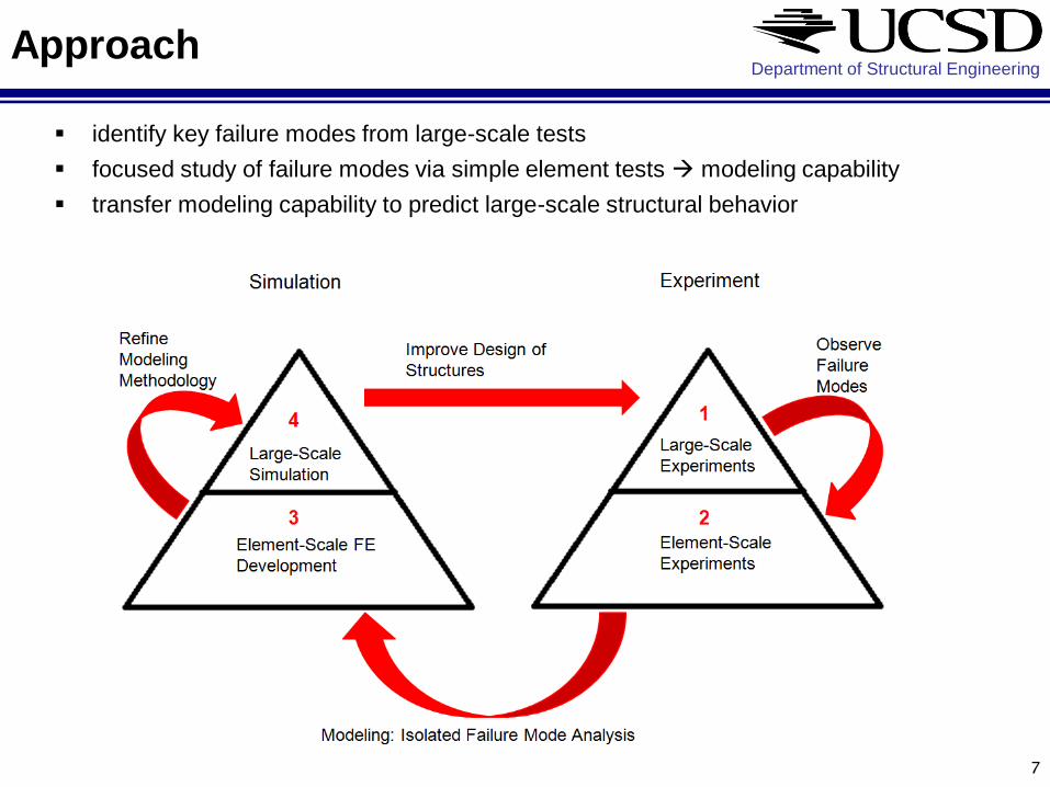
Topic I:
Summary of Large Scale Experiments
FrameXX Series Specimens
Stringer and C-Frame Reinforced Skin Specimens
StringerXX Specimens Stringer-
Reinforced Skin Specimens
Qnty: 4 Qnty: 7
Co-Cured Composite
Skin &
Stringers
Composite Frames(C-Shape)
Shear Ties:- Composite
- 7075 Al Alloy
Blunt Impact Loading Zone – on Skin Directly Onto
Shear TiesReplaced Central 9
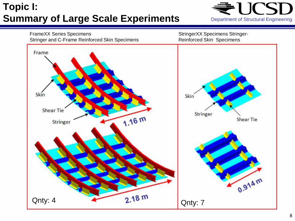
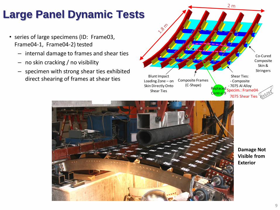
• series of large specimens (ID: Frame03, Frame04-1, Frame04-2) tested
– internal damage to frames and shear ties
– no skin cracking / no visibility
– specimen with strong shear ties exhibited direct shearing of frames at shear ties
9
Large Panel Dynamic Tests
Specim.: Frame04-1
7075 Shear Ties
Damage Not Visible from Exterior
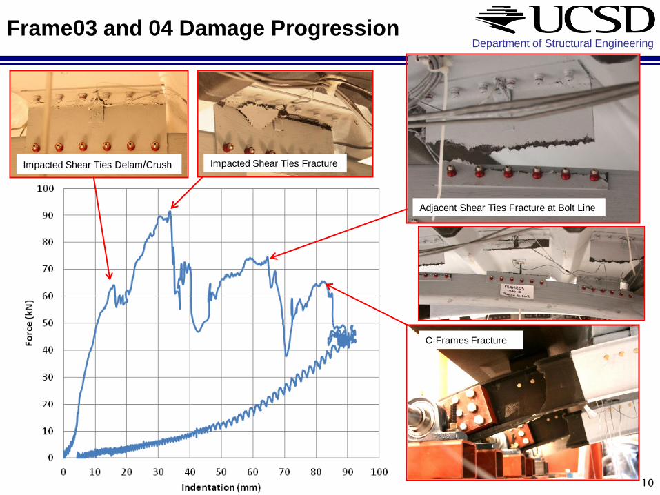
Department of Structural Engineering Frame03 and 04 Damage Progression
10
Impacted Shear Ties Delam/Crush Impacted Shear Ties Fracture
Adjacent Shear Ties Fracture at Bolt Line
C-Frames Fracture

• partially-cracked frame –
damage away from impact site
• shear ties delamination
• cracked/crushed shear ties in
all specimens
• stringer-skin disbond
• stringer heel crack
11
Partially-cracked frames – from specimen Frame02
Flange
Flange
& Web
Flange
Damage Modes Summary
Low visibility of C-frame cracks
located away from impact
Department of Structural Engineering
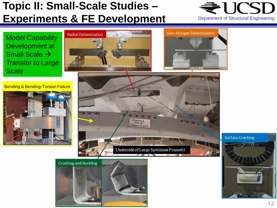
12
Topic II: Small-Scale Studies –
Experiments & FE Development
Bending & Bending-Torsion Failure
Model Capability
Development at
Small Scale
Transfer to Large
Scale
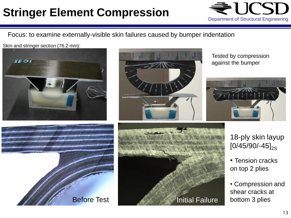
Department of Structural Engineering Stringer Element Compression
13
Focus: to examine externally-visible skin failures caused by bumper indentation
Tested by compression
against the bumper
Skin and stringer section (76.2 mm):
Before Test Initial Failure
18-ply skin layup
[0/45/90/-45]2S
• Tension cracks
on top 2 plies
• Compression and
shear cracks at
bottom 3 plies
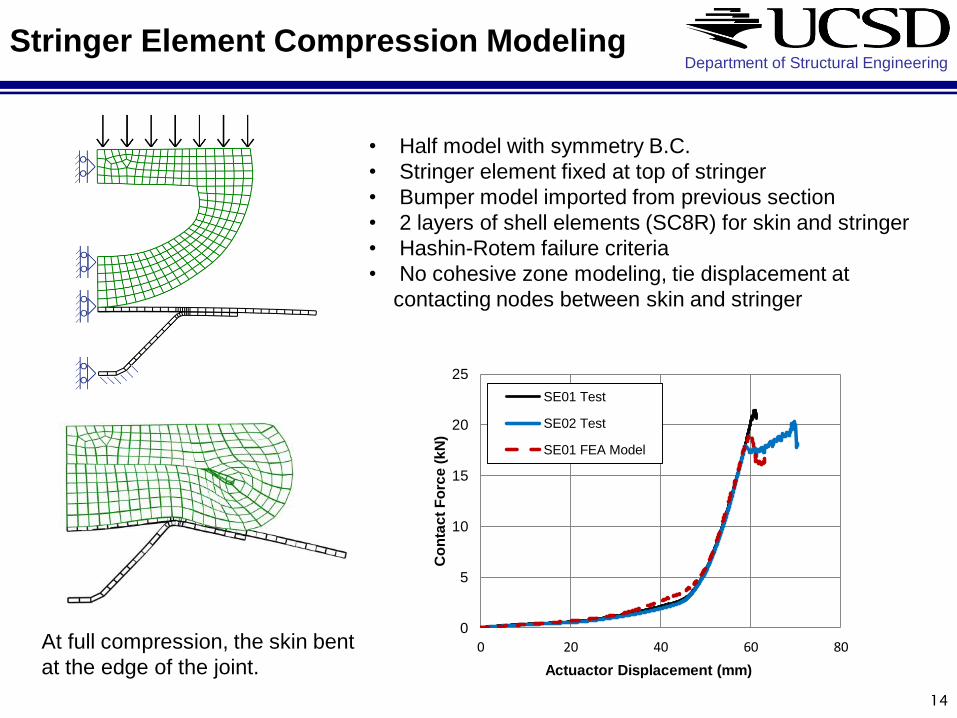
Department of Structural Engineering Stringer Element Compression Modeling
14
• Half model with symmetry B.C.
• Stringer element fixed at top of stringer
• Bumper model imported from previous section
• 2 layers of shell elements (SC8R) for skin and stringer
• Hashin-Rotem failure criteria
• No cohesive zone modeling, tie displacement at
contacting nodes between skin and stringer
At full compression, the skin bent
at the edge of the joint.
0
5
10
15
20
25
0 20 40 60 80
Co
nta
ct
Fo
rce
(k
N)
Actuactor Displacement (mm)
SE01 Test
SE02 Test
SE01 FEA Model
Department of Structural Engineering
15
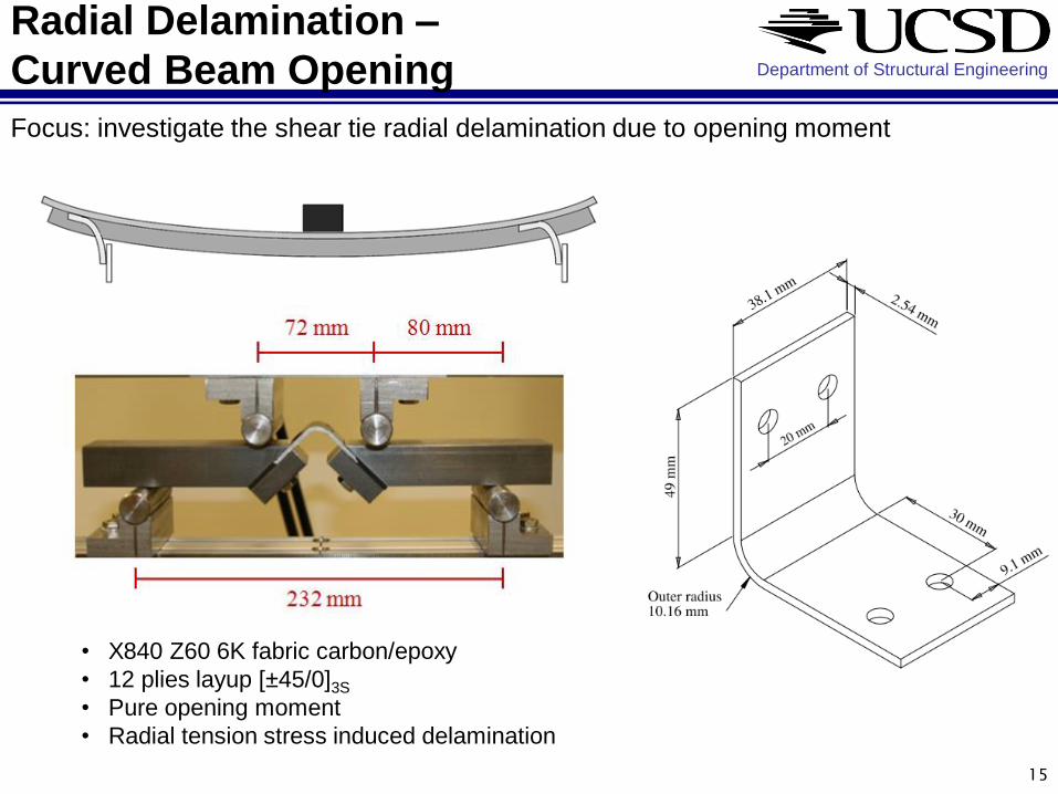
Radial Delamination –
Curved Beam Opening
• X840 Z60 6K fabric carbon/epoxy
• 12 plies layup [±45/0]3S
• Pure opening moment
• Radial tension stress induced delamination
Focus: investigate the shear tie radial delamination due to opening moment
Department of Structural Engineering
16
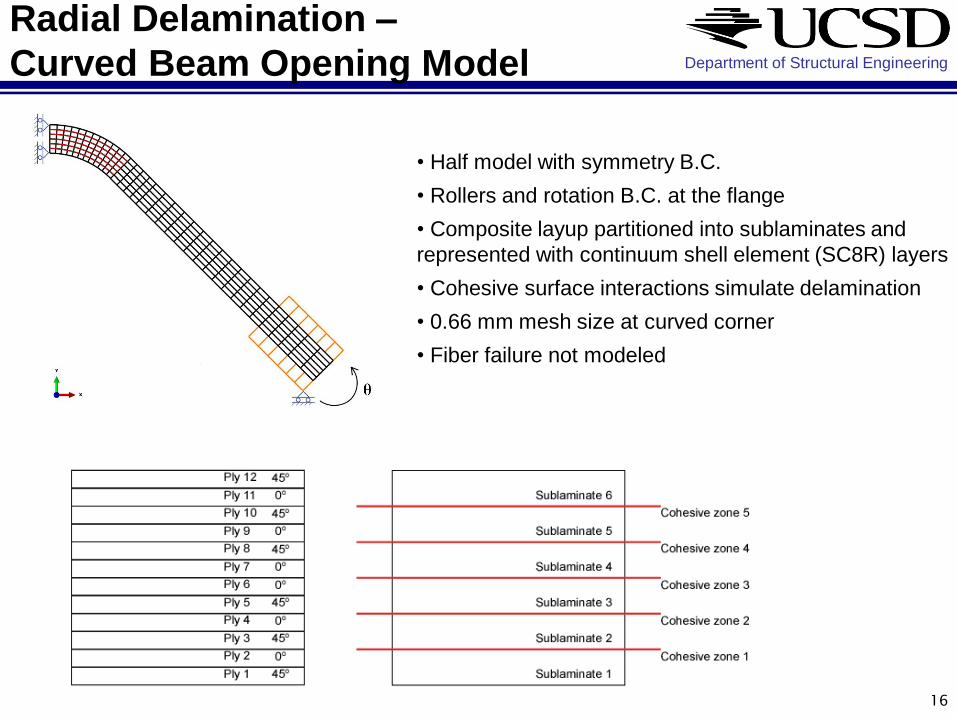
Radial Delamination –
Curved Beam Opening Model
• Half model with symmetry B.C.
• Rollers and rotation B.C. at the flange
• Composite layup partitioned into sublaminates and
represented with continuum shell element (SC8R) layers
• Cohesive surface interactions simulate delamination
• 0.66 mm mesh size at curved corner
• Fiber failure not modeled
Department of Structural Engineering
17
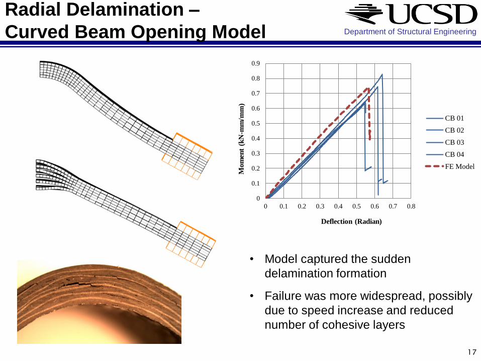
Radial Delamination –
Curved Beam Opening Model
0
0.1
0.2
0.3
0.4
0.5
0.6
0.7
0.8
0.9
0 0.1 0.2 0.3 0.4 0.5 0.6 0.7 0.8
Mo
men
t (k
N-m
m/m
m)
Deflection (Radian)
CB 01
CB 02
CB 03
CB 04
FE Model
• Model captured the sudden
delamination formation
• Failure was more widespread, possibly
due to speed increase and reduced
number of cohesive layers

Department of Structural Engineering
18
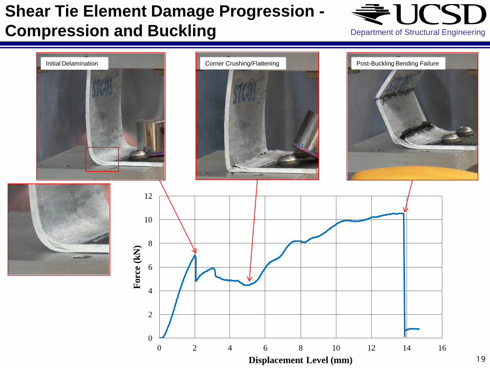
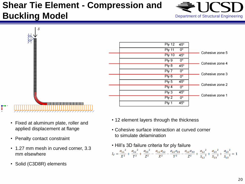
Shear Tie Element - Compression and
Buckling
Focus: study shear tie radial delamination and crushing due to compression loading
Delamination and fiber crushing
expected at point B:
• Constant shear force
• Peak interlaminar shear at B
• Linearly varying moment
• Peak interlaminar tension at B
Pivot on top
Bolted at the bottom
Department of Structural Engineering
19
Corner Crushing/Flattening Post-Buckling Bending Failure
0
2
4
6
8
10
12
0 2 4 6 8 10 12 14 16
Forc
e (
kN
)
Displacement Level (mm)
Initial Delamination
Shear Tie Element Damage Progression -
Compression and Buckling
Department of Structural Engineering
20
• Fixed at aluminum plate, roller and
applied displacement at flange
• Penalty contact constraint
• 1.27 mm mesh in curved corner, 3.3
mm elsewhere
• Solid (C3D8R) elements
• 12 element layers through the thickness
• Cohesive surface interaction at curved corner
to simulate delamination
• Hill’s 3D failure criteria for ply failure
Shear Tie Element - Compression and
Buckling Model

Department of Structural Engineering
21
0
2
4
6
8
10
12
14
0 2 4 6 8 10 12 14 16
Co
nta
ct F
orc
e (
kN)
Crosshead Displacement (mm)
STC02
12 Layers Solid FEM
a. b.
c.
a. b. c.
Shear Tie Element - Compression and
Buckling Model
Simulation
Animation

Department of Structural Engineering
22
C-Frame Element
Bending & Bending-Torsion
• C-frame test specimen
• short section w/ extension arm
• fixed end boundary condition
• loaded end:
• 2 point connection bending
• 1 point bending + torsion
Gage Section: 160 mm End Tabs End Tabs

Department of Structural Engineering
23
C-Frame Element
Bending Test Results (A2)
7 Strain
Gauges
Back-to-Back
Outside of Flange Only
1 Rosette
Near Fixed-End Mid-Span
Flange
Buckling
Modeling
Work
Ongoing
Comp. Bending Failure (A2)

Department of Structural Engineering
Modeling definitions for element-level small
scale studies exported into large-scale models
24
Topic III:
Transferability of FE Model Definitions
In Progress
Simulation
Animation

Department of Structural Engineering Frame03 Model – Key Failure events
25
0
10
20
30
40
50
60
70
80
90
100
0 10 20 30 40 50 60 70 80 90 100
Fo
rce
(k
N)
Indentation (mm)
Experimental(CombinedFrame03 & 04)
FE Model (12Layer Shear Tie,Solid Element)
a
b
c
d
Failure events in the model:
a. Impacted shear tie radial delamination
b. Impacted shear tie corner crushing
c. Impacted shear tie fracture
d. Adjacent shear tie and C-frame fracture
Cross-section view
through C-frame

Department of Structural Engineering Modeling Capabilities Plan
26
Glancing Impact Size, Complex Internal
Structure, Geom., Joints
Various Impactors &
Scenarios (vo)
Models of
Generic
Curved Panel
Specimens
- Static
- Dynamic
Experimental
Validation
Capture Key Failure
Modes (Major Damage)
Damage Initiation Criteria
Damage Progression
Dynamic Effects
Externally Visibility
Establish
Capabilities
Define
Methodologies
With Element
Level Tests
flig
htg
lobal.com
/FlightB
logger
Apply to study and predict response for:

NDE Methods for Detecting Major Damage in
Internal Composite Structural Components
• pitch-catch guided ultrasonic
wave (GUW) approach
• C-frame is like 1D waveguide
– wave transmission along length
affected by damage
– broken shear tie and frame
will attenuate/modify signal
• key issues:
– find dominant frequencies
associated with those
waves/modes sensitive to
damage
– complex geometry, many
interfaces
– parallel wave path through
skin
27

GUW Tests on Damaged C-Frame
28
Damaged C-frame installed in panel:
• significant attenuation (55%) through damaged path
• crack in C-frame flange detectable for sensors
directly mounted to frame – next: test sensing
through skin
Frequency sweep conducted to find dominant
frequencies (80 kHz shown below).
Expect: presence of damage attenuation of signal.
Excitation
Sensor
Sensor
Pristine C-Frame
Partial
Crack
Sensors located
305 mm (12 in.)
from Excitation.
Excitation: 5-
cycle sinusoidal
burst sent at
various
frequencies.

29
GUW Tests Through Shear Ties
Excite on Skin at Shear Ties
Measure in Frame
– observe how waves propagate
through interfaces and bolt lines
– observe capability of GUW
method to detecting damaged
shear ties
Left Mid Right
Excitation on Skin Sensing on Frame
Skin
Frame Shear Ties

30
Comparison
Mid Sensor
Measurements
• GUW Test: Skin to Frame
– Shear Tie 11 (Pristine)
– Shear Ties 07 and 06 are partially
cracked at the corner
– Shear Ties 03 and 02 are fully
cracked along the bolt lines
Shear Ties:
Pristine
½ Cracked
Fully Cracked

31
Exterior-Only GUW Tests (Skin-to-Skin) • Frame 02 Panel With Damaged Shear Ties (2, 3, 6, and 7)
• Excitation and Sensing from Outer Skin Surface at Shear Ties
C-frame 1
C-frame 2
C-frame 3
Shear Tie 1 Shear Tie 2 Shear Tie 3 Shear Tie 4
Shear Tie 5 Shear Tie 6 Shear Tie 7
Shear Tie 8
Shear Tie 9 Shear Tie 10 Shear Tie 11 Shear Tie 12
Shear Tie 7
Panel Inside View
32
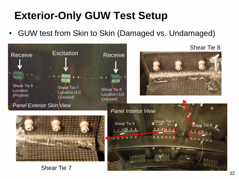
Exterior-Only GUW Test Setup
• GUW test from Skin to Skin (Damaged vs. Undamaged)
Excitation Receive Receive
Panel Exterior Skin View
Shear Tie 7
Shear Tie 8
Panel Interior View
Shear Tie 6 Shear Tie 7
Shear Tie 8
Shear Tie 6
Location
(Pristine)
Shear Tie 7
Location (1/2
Cracked)
Shear Tie 8
Location (1/2
Cracked)
33
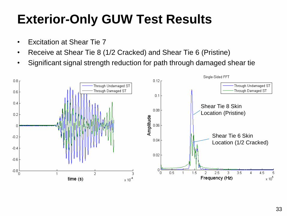
Exterior-Only GUW Test Results
• Excitation at Shear Tie 7
• Receive at Shear Tie 8 (1/2 Cracked) and Shear Tie 6 (Pristine)
• Significant signal strength reduction for path through damaged shear tie
Shear Tie 8 Skin
Location (Pristine)
Shear Tie 6 Skin
Location (1/2 Cracked)
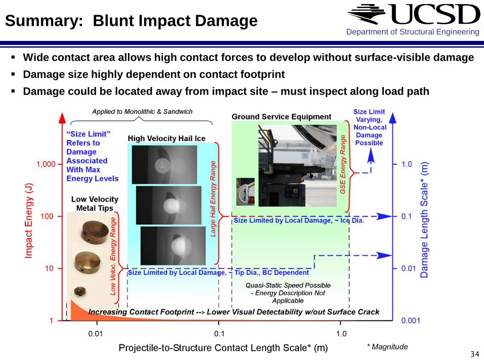
Department of Structural Engineering Summary: Blunt Impact Damage
Wide contact area allows high contact forces to develop without surface-visible damage
Damage size highly dependent on contact footprint
Damage could be located away from impact site – must inspect along load path
34
Department of Structural Engineering
Summary: Prediction & Detection
HEWABI Damage Prediction
• detailed FE prediction possible
» focused element-level experiments enabled accurate analysis procedure
development
– due to their simplified geometries, loading conditions, and isolated
failure modes
» models capturing correct physical phenomena can be transferred to
accurately predict large-scale structure response
• must account for early failure modes to capture subsequent history and final
failure mode
» e.g., shear ties in large panel tests
Damage Detection
• guided ultrasonic wave (GUW) methods have demonstrated proof of concept
(much work to do still)
» significant GUW attenuation through cracked frames and shear ties
» exterior-only measurements show sensitivity
35

Department of Structural Engineering
Future Plans:
Frame to Floor Structure Interaction
36
Quarter-barrel panel including
floor structures will be designed
to reflect more actual aircraft
fuselage
frame-to-floor joint
proper frame-end torsional
stiffness BC
more substantial,
continuous shear ties
Main focus will be Frame to Floor
Interaction - How damage
development will be affected
according to new BCs and stress
concentration factor.
impact locations near the
floor structures
Impact near floor structures
Related Documents