High-efficiency class E/F 3 power amplifiers with extended maximum operating frequency Chang Liu 1 , Xiang-Dong Huang 2a) , and Qian-Fu Cheng 1 1 School of Microelectronics, Tianjin University, Tianjin 300072, China 2 School of Electrical and Information Engineering, Tianjin University, Tianjin 300072, China a) [email protected] Abstract: This paper presents high-efficiency class-E/F 3 power amplifiers with extended maximum operating frequency ( f max ) using a novel method of a transmission-line compensation circuit (TLCC). Theoretical analysis is presented in order to obtain circuit component values, which compensate the excess output capacitance C x and satisfy the required impedances of the class-E/F 3 power amplifiers at the fundamental frequency and harmonics. The proposed circuit, whose f max is 4 times higher than the conventional structure, has been designed, fabricated, and measured. Besides, high-per- formance results with the output power of 40.3 dBm, drain efficiency of 82.9% have been achieved. Keywords: class-E/F 3 , high-efficiency power amplifier (PA), maximum operating frequency, transmission-line compensation circuit (TLCC) Classification: Power devices and circuits References [1] F. J. Ortega-Gonzalez, et al.: “High-power wideband L-band suboptimum class-E power amplifier,” IEEE Trans. Microw. Theory Techn. 61 (2013) 3712 (DOI: 10.1109/TMTT.2013.2279366). [2] N. Sokal and A. Sokal: “Class E-A new class of high-efficiency tuned single- ended switching power amplifiers,” IEEE J. Solid-State Circuits 10 (1975) 168 (DOI: 10.1109/JSSC.1975.1050582). [3] F. H. Raab: “Idealized operation of the class E tuned power amplifier,” IEEE Trans. Circuits Syst. 24 (1977) 725 (DOI: 10.1109/TCS.1977.1084296). [4] A. Sheikhi, et al.: “High-efficiency class-E-1 and class-F/E power amplifiers at any duty ratio,” IEEE Trans. Ind. Electron. 63 (2016) 840 (DOI: 10.1109/TIE. 2015.2478404). [5] M. D. Weiss, et al.: “Linearity of X-band class-F power amplifiers in high- efficiency transmitters,” IEEE Trans. Microw. Theory Techn. 49 (2001) 1174 (DOI: 10.1109/22.925515). [6] Y. Y. Woo, et al.: “Analysis and experiments for high-efficiency class-F and inverse class-F power amplifiers,” IEEE Trans. Microw. Theory Techn. 54 (2006) 1969 (DOI: 10.1109/TMTT.2006.872805). [7] J. H. Kim, et al.: “Modeling and design methodology of high-efficiency class-F © IEICE 2018 DOI: 10.1587/elex.15.20180503 Received May 17, 2018 Accepted May 24, 2018 Publicized June 12, 2018 Copyedited June 25, 2018 1 LETTER IEICE Electronics Express, Vol.15, No.12, 1–10

Welcome message from author
This document is posted to help you gain knowledge. Please leave a comment to let me know what you think about it! Share it to your friends and learn new things together.
Transcript
High-efficiency class E/F3power amplifiers withextended maximumoperating frequency
Chang Liu1, Xiang-Dong Huang2a), and Qian-Fu Cheng11 School of Microelectronics, Tianjin University, Tianjin 300072, China2 School of Electrical and Information Engineering, Tianjin University,
Tianjin 300072, China
Abstract: This paper presents high-efficiency class-E/F3 power amplifiers
with extended maximum operating frequency ( fmax) using a novel method of
a transmission-line compensation circuit (TLCC). Theoretical analysis is
presented in order to obtain circuit component values, which compensate
the excess output capacitance Cx and satisfy the required impedances of the
class-E/F3 power amplifiers at the fundamental frequency and harmonics.
The proposed circuit, whose fmax is 4 times higher than the conventional
structure, has been designed, fabricated, and measured. Besides, high-per-
formance results with the output power of 40.3 dBm, drain efficiency of
82.9% have been achieved.
Keywords: class-E/F3, high-efficiency power amplifier (PA), maximum
operating frequency, transmission-line compensation circuit (TLCC)
Classification: Power devices and circuits
References
[1] F. J. Ortega-Gonzalez, et al.: “High-power wideband L-band suboptimumclass-E power amplifier,” IEEE Trans. Microw. Theory Techn. 61 (2013) 3712(DOI: 10.1109/TMTT.2013.2279366).
[2] N. Sokal and A. Sokal: “Class E-A new class of high-efficiency tuned single-ended switching power amplifiers,” IEEE J. Solid-State Circuits 10 (1975) 168(DOI: 10.1109/JSSC.1975.1050582).
[3] F. H. Raab: “Idealized operation of the class E tuned power amplifier,” IEEETrans. Circuits Syst. 24 (1977) 725 (DOI: 10.1109/TCS.1977.1084296).
[4] A. Sheikhi, et al.: “High-efficiency class-E-1 and class-F/E power amplifiers atany duty ratio,” IEEE Trans. Ind. Electron. 63 (2016) 840 (DOI: 10.1109/TIE.2015.2478404).
[5] M. D. Weiss, et al.: “Linearity of X-band class-F power amplifiers in high-efficiency transmitters,” IEEE Trans. Microw. Theory Techn. 49 (2001) 1174(DOI: 10.1109/22.925515).
[6] Y. Y. Woo, et al.: “Analysis and experiments for high-efficiency class-F andinverse class-F power amplifiers,” IEEE Trans. Microw. Theory Techn. 54(2006) 1969 (DOI: 10.1109/TMTT.2006.872805).
[7] J. H. Kim, et al.: “Modeling and design methodology of high-efficiency class-F
© IEICE 2018DOI: 10.1587/elex.15.20180503Received May 17, 2018Accepted May 24, 2018Publicized June 12, 2018Copyedited June 25, 2018
1
LETTER IEICE Electronics Express, Vol.15, No.12, 1–10
and class-F−1 power amplifiers,” IEEE Trans. Microw. Theory Techn. 59(2011) 153 (DOI: 10.1109/TMTT.2010.2090167).
[8] K. Honjo: “A simple circuit synthesis method for microwave class-F ultra-high-efficiency amplifiers with reactance-compensation circuits,” Solid-StateElectron. 44 (2000) 1477 (DOI: 10.1016/S0038-1101(00)00061-7).
[9] S. D. Kee, et al.: “The class-E/F family of ZVS switching amplifiers,” IEEETrans. Microw. Theory Techn. 51 (2003) 1677 (DOI: 10.1109/TMTT.2003.812564).
[10] A. Grebennikov: “High-efficiency class E/F lumped and transmission-linepower amplifiers,” IEEE Trans. Microw. Theory Techn. 59 (2011) 1579 (DOI:10.1109/TMTT.2011.2114672).
[11] F. H. Raab: “Suboptimum operation of class-E RF power amplifiers,” Proc. RFTechnol. Expo. (1989) 85.
[12] A. Sheikhi, et al.: “Effect of gate-to-drain and drain-to-source parasiticcapacitances of MOSFET on the performance of class-E/F3 power amplifier,”IET Circuits Dev. Syst. 10 (2016) 192 (DOI: 10.1049/iet-cds.2015.0140).
[13] A. Sheikhi, et al.: “A design methodology of class-E/F3 power amplifierconsidering linear external and nonlinear drain–source capacitance,” IEEETrans. Microw. Theory Techn. 65 (2017) 548 (DOI: 10.1109/TMTT.2016.2635658).
[14] M. Hayati, et al.: “Effect of nonlinearity of parasitic capacitance on analysisand design of class E/F3 power amplifier,” IEEE Trans. Power Electron. 30(2015) 4404 (DOI: 10.1109/TPEL.2014.2358580).
[15] M. Hayati, et al.: “Design and analysis of class E/F3 power amplifier withnonlinear shunt capacitance at nonoptimum operation,” IEEE Trans. PowerElectron. 30 (2015) 727 (DOI: 10.1109/TPEL.2014.2308280).
[16] J. Cumana, et al.: “An extended topology of parallel-circuit class-E poweramplifier to account for larger output capacitances,” IEEE Trans. Microw.Theory Techn. 59 (2011) 3174 (DOI: 10.1109/TMTT.2011.2168971).
[17] Y. Leng, et al.: “An extended topology of parallel-circuit class-E poweramplifier using transmission line compensation,” IEEE Trans. Microw. TheoryTechn. 61 (2013) 1628 (DOI: 10.1109/TMTT.2013.2248743).
[18] Y. S. Lee and Y. H. Jeong: “A high-efficiency class-E GaN HEMT poweramplifier for WCDMA applications,” IEEE Microw. Wireless Compon. Lett.17 (2007) 622 (DOI: 10.1109/LMWC.2007.901803).
[19] Q. F. Cheng, et al.: “High-efficiency parallel-circuit class-E power amplifierwith distributed T-shaped compensation circuit,” IEICE Electron. Express 13(2016) 20160570 (DOI: 10.1587/elex.13.20160570).
[20] C. C. Rong, et al.: “A class E GaN microwave power amplifier accountingfor parasitic inductance of transistor,” IEICE Electron. Express 14 (2017)20170127 (DOI: 10.1587/elex.14.20170127).
[21] Y.-S. Lee, et al.: “A high-efficiency GaN-based power amplifier employinginverse class-E topology,” IEEE Microw. Wireless Compon. Lett. 19 (2009)593 (DOI: 10.1109/LMWC.2009.2027095).
[22] Sh. Chen and Q. Xue: “A class-F power amplifier with CMRC,” IEEE Microw.Wireless Compon. Lett. 21 (2011) 31 (DOI: 10.1109/LMWC.2010.2091265).
[23] J. X. Xu, et al.: “High-efficiency filter-integrated class-F power amplifier basedon dielectric resonator,” IEEE Microw. Wireless Compon. Lett. 27 (2017) 827(DOI: 10.1109/LMWC.2017.2734778).
[24] M. Helaoui and F. M. Ghannouchi: “Optimizing losses in distributedmultiharmonic matching networks applied to the design of an RF GaN poweramplifier with higher than 80% power-added efficiency,” IEEE Trans. Microw.Theory Techn. 57 (2009) 314 (DOI: 10.1109/TMTT.2008.2009905).
[25] J. H. Kim, et al.: “High efficiency HBT power amplifier utilizing optimum
© IEICE 2018DOI: 10.1587/elex.15.20180503Received May 17, 2018Accepted May 24, 2018Publicized June 12, 2018Copyedited June 25, 2018
2
IEICE Electronics Express, Vol.15, No.12, 1–10

phase of second harmonic source impedance,” IEEE Microw. WirelessCompon. Lett. 25 (2015) 721 (DOI: 10.1109/LMWC.2015.2479837).
[26] M. Thian, et al.: “High-efficiency harmonic peaking class-EF power amplifierswith enhanced maximum operating frequency,” IEEE Trans. Microw. TheoryTechn. 63 (2015) 659 (DOI: 10.1109/TMTT.2014.2386327).
[27] C. C. Rong, et al.: “A broadband microwave GaN HEMTs class EF3 poweramplifier with π-type network,” IEICE Electron. Express 14 (2017) 20170260(DOI: 10.1587/elex.14.20170260).
[28] T. Sharma, et al.: “High-efficiency input and output harmonically engineeredpower amplifiers,” IEEE Trans. Microw. Theory Techn. 66 (2018) 1002 (DOI:10.1109/TMTT.2017.2756046).
1 Introduction
With the rapid development of RF transmission systems, it is gradually required
that power amplifiers (PAs) operate with high efficiency, high output power, good
linearity and so on. Among these requirements, high-efficiency is the most critical
one, especially in high power or battery-powered applications [1]. Therefore, it has
been a hot topic to develop high-efficiency PAs.
The class-E PA is one of the well-known high-efficiency PAs due to its
relatively simple realization and elimination of turn-on switching losses because
of a soft-switching operation mode [2, 3]. However, as far as the peak drain voltage
(Vmax) is concerned, the class-E approach is not a good choice for practical
applications because of the relatively large switch stresses to active devices,
especially in the integrated circuit [4]. Fortunately, differing from the class-E PA,
the class-F/F−1 PA has lower Vmax and higher attainable operating frequencies [5].
Whereas, due to the tuning requirements [6, 7] and the lack of a simple circuit
implementation, e.g., [8], the class-F/F−1 PA also has performance limitations.
Based on the advantages and disadvantages in class-E PA [2, 3, 4] and class-F/F−1
PA [5, 6, 7, 8], it is of great significance to combine the two high-efficiency PAs
and present a new PA mode of operation: class-E/F3 PA [9, 10, 12, 13, 14, 15],
which not only realizes a relatively simple structure, but also reduces the peak
voltage Vmax [9, 10]. However, in the class-E/F3 power amplifier, the optimum
shunt capacitance (C) decreases with the increase of the maximum operating
frequency (fmax, is defined as the maximum frequency at which the device output
capacitance Cout can provide the shunt susceptance Bopt required for optimum
operation [11]) for the prescribed output power P0 and DC supply voltage VDS
[12, 13]. In practical applications, C becomes smaller than Cout in the high fmax
[14], which results in excess output capacitance Cx (¼ Cout � C). Owing to this, the
class-E/F3 PA operates at a suboptimal condition and its efficiency consequently
decreases a lot [15]. In a word, the fmax of the conventional class-E/F3 PA is
limited to hundreds of MHz when keeping its optimal mode of operation, thus
representing a crucial issue.
In this paper, in order to further increase the fmax of a class-E/F3 power
amplifier to GHz when operating at an optimal condition, a novel method of a
transmission-line compensation circuit (TLCC) is proposed. This structure com-
© IEICE 2018DOI: 10.1587/elex.15.20180503Received May 17, 2018Accepted May 24, 2018Publicized June 12, 2018Copyedited June 25, 2018
3
IEICE Electronics Express, Vol.15, No.12, 1–10
pensates Cx at both the fundamental and harmonic frequencies. Therefore, the
TLCC bypasses the limitations on fmax of the class-E/F3 PA. Besides, a high
performance PA, whose fmax is 4 times larger than the conventional structure, is
designed and fabricated to validate the theory. In brief, due to its extended fmax,
simple construction and low-loss implementation at high frequencies, the proposed
circuit is more suitable for use as a class-E/F3 amplifier operating in the microwave
band.
2 Class-E/F3 PAs
2.1 Standard idealized class-E/F3 PAs
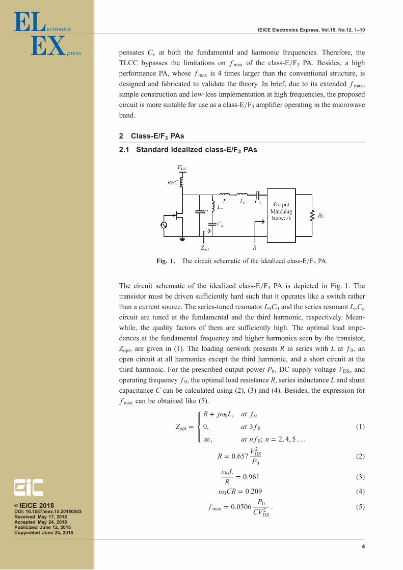
The circuit schematic of the idealized class-E/F3 PA is depicted in Fig. 1. The
transistor must be driven sufficiently hard such that it operates like a switch rather
than a current source. The series-tuned resonator L0C0 and the series resonant LnCn
circuit are tuned at the fundamental and the third harmonic, respectively. Mean-
while, the quality factors of them are sufficiently high. The optimal load impe-
dances at the fundamental frequency and higher harmonics seen by the transistor,
Zopt, are given in (1). The loading network presents R in series with L at f0, an
open circuit at all harmonics except the third harmonic, and a short circuit at the
third harmonic. For the prescribed output power P0, DC supply voltage VDS, and
operating frequency f0, the optimal load resistance R, series inductance L and shunt
capacitance C can be calculated using (2), (3) and (4). Besides, the expression for
fmax can be obtained like (5).
Zopt ¼R þ j!0L; at f0
0; at 3f0
1; at nf0; n ¼ 2; 4; 5 . . .
8><>:
ð1Þ
R ¼ 0:657V2DS
P0
ð2Þ!0L
R¼ 0:961 ð3Þ
!0CR ¼ 0:209 ð4Þfmax ¼ 0:0506
P0
CV 2DS
: ð5Þ
Fig. 1. The circuit schematic of the idealized class-E/F3 PA.
© IEICE 2018DOI: 10.1587/elex.15.20180503Received May 17, 2018Accepted May 24, 2018Publicized June 12, 2018Copyedited June 25, 2018
4
IEICE Electronics Express, Vol.15, No.12, 1–10
Ideally, the shunt capacitance C can entirely furnish the device output capaci-
tance Cout. By substituting C ¼ Cout, fmax can be rewritten as
fmax ¼ 0:0506P0
CoutV 2DS
: ð6Þ
2.2 Class-E/F3 PA with extended fmax
From (5), it follows that C decreases with the increase of fmax for the prescribed
P0 and VDS. In practical applications, C becomes smaller than the device output
capacitance Cout in the high fmax, which results in excess output capacitance Cx
(¼ Cout � C). The enhancement of fmax is achieved by compensating Cx. This
translates into higher fmax expressed in (7) as follows, where Cx is defined as KC
(K > 0):
fmax ¼ 0:0506P0
ðCout � CXÞV 2DS
¼ 0:0506ð1 þ KÞ P0
CoutV 2DS
ð7Þ
Compared with the original result given in (6), fmax is increased by 1 þ K
times. which can be realized by the proposed TLCC given in Section 3.
3 TL compensation circuit for class-E/F3 PA
Some methods including a lumped-element equivalent circuit [16], and TLCC [17]
have been presented to compensate Cx and extend fmax in other high-efficiency
switch-mode PAs. However, the method in [16] has been restricted by the lumped-
element model and large parasitic losses at high frequencies [17]. Therefore, as
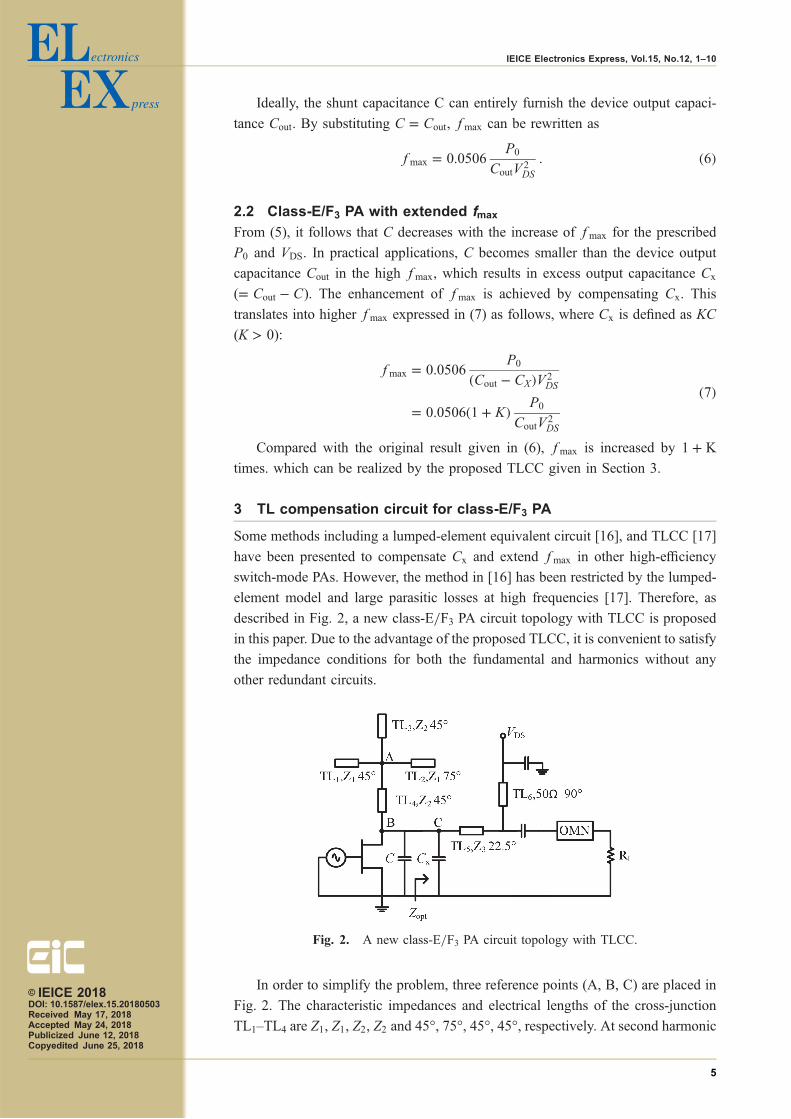
described in Fig. 2, a new class-E/F3 PA circuit topology with TLCC is proposed
in this paper. Due to the advantage of the proposed TLCC, it is convenient to satisfy
the impedance conditions for both the fundamental and harmonics without any
other redundant circuits.
In order to simplify the problem, three reference points (A, B, C) are placed in
Fig. 2. The characteristic impedances and electrical lengths of the cross-junction
TL1–TL4 are Z1, Z1, Z2, Z2 and 45°, 75°, 45°, 45°, respectively. At second harmonic
Fig. 2. A new class-E/F3 PA circuit topology with TLCC.
© IEICE 2018DOI: 10.1587/elex.15.20180503Received May 17, 2018Accepted May 24, 2018Publicized June 12, 2018Copyedited June 25, 2018
5
IEICE Electronics Express, Vol.15, No.12, 1–10

frequency, the cross-junction can provide an open termination at the point B. At the
third harmonic, TL1 resonates with TL2 in order to provide an open-circuit at the
point A. Therefore, the cross-junction seen by the point B at the third harmonic can
be simplified as a 3�=4 transmission-line, which can provide a short termination so
as to satisfy the condition of the harmonic impedance like (1).
Furthermore, the electrical length of the drain biasing TL6 in Fig. 2 is 90° and it
consequently provides a short-circuit termination at 2!0. Thus, the shorted series
line TL5 behaves like an inductance La at the second harmonic
jZ3 tanð2�3Þ ¼ j2!0La: ð8Þwhere, �3 and Z3 are the electrical length and characteristic impedance of TL5,
respectively. This inductance La must be resonated with Cx at the point C, in order
to compensate Cx and provide the required open circuit for the second harmonic
like (1), and hence
j2!0CX þ 1
j2!0La¼ 0: ð9Þ
Note that there are two degrees of freedom ð�3; Z3Þ. Taking the fourth harmonic
into consideration, it is better to select 22.5° as the electrical length of TL5 because
of its open-circuit termination for the fourth harmonic at the point C. Thus, the
characteristic impedance of TL5 can be determined by (8)–(9).
At 4!0, since TL1 and TL3 represent the open-circuited terminations at the
point A, the cross-junction at the point B can be simplified as an inductance Lb:
Z1j tanð75 � 4Þ ¼ j4!0Lb: ð10Þ
Then, like the compensation for the second harmonic, the inductance Lb must
be resonated with Cx at the point C, in order to compensate Cx and provide the
required open circuit for the fourth harmonic like (1), and hence
j4!0CX þ 1
j4!0Lb¼ 0: ð11Þ
The characteristic impedance Z1 of TL1–TL2 can be determined by (10)–(11).
It should be noted that the electrical length of TL2 is 75° rather than 15° at the
fundamental. Although TL2 with electrical length of 15° can also resonate with TL1
at the third harmonic and its physical size is shorter, TL2 with electrical length of
75° has been employed because of its wider tuning space for characteristic
impedance Z2, so as to compensate Cx at 5!0 as far as possible.
Finally, at !0, an output match network (OMN) is created in order to
compensate Cx and match the 50Ω load to optimal load reactance like (1).
4 Design and verification
A design example of the class-E/F3 PA with TLCC is presented in order to better
understand the theoretical analysis described in the previous sections.
The design objectives are set as follows: VDS ¼ 28V and Pout ¼ 10W. The
transistor used in implementation is a CGH40010F GaN HEMT from Wolfspeed
with Cout ¼ 1:2 pF. Substituting these values into (6) yields fmax ¼ 0:54GHz.
According to (5), if the operation frequency is increased to 2.14GHz, whose fmax
© IEICE 2018DOI: 10.1587/elex.15.20180503Received May 17, 2018Accepted May 24, 2018Publicized June 12, 2018Copyedited June 25, 2018
6
IEICE Electronics Express, Vol.15, No.12, 1–10
is 4 times larger than that of the conventional circuit, the value of the shunt
capacitance C is decreased to 0.3 pF. Since Cout ¼ 1:2 pF, the excess capacitance Cx
required is 0.9 pF, implying K ¼ 3. Based on the theoretical analysis in the previous
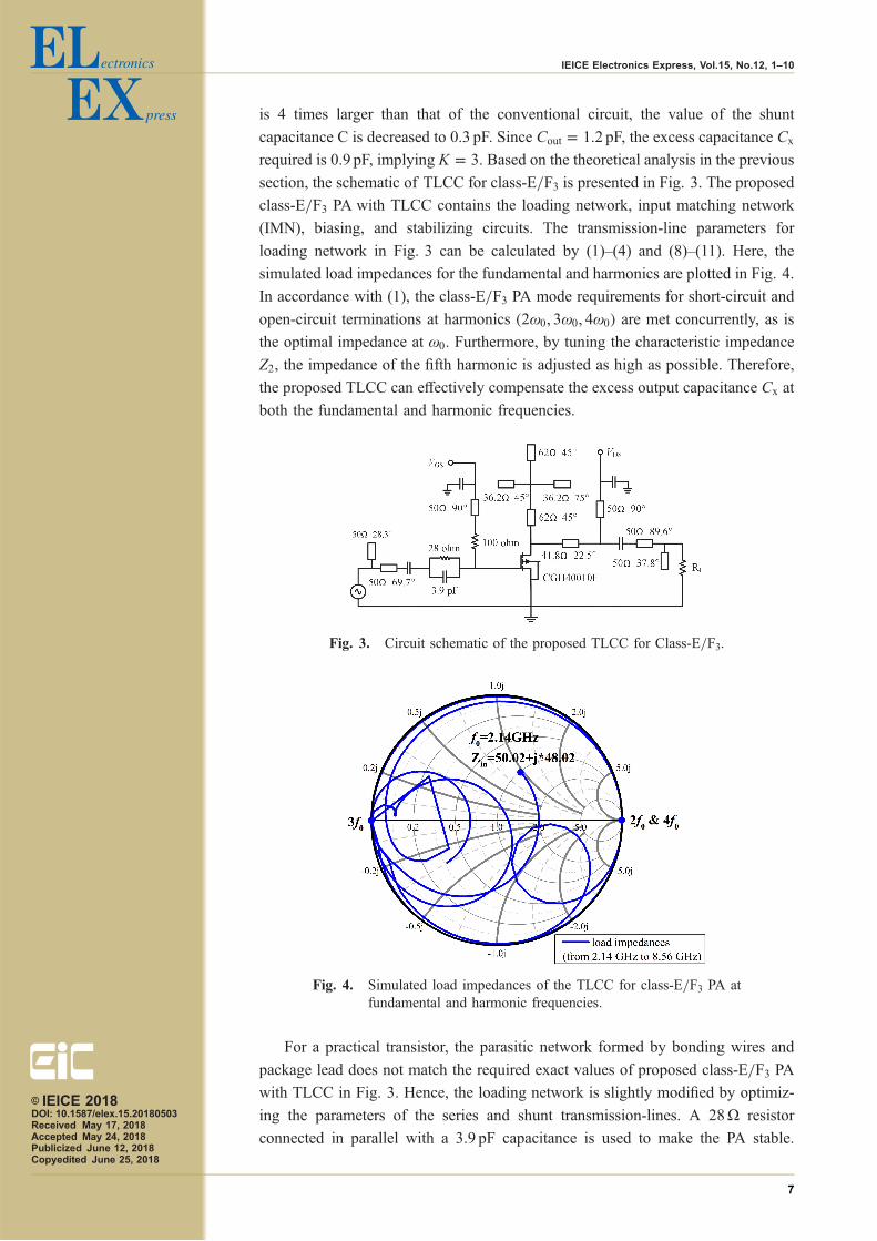
section, the schematic of TLCC for class-E/F3 is presented in Fig. 3. The proposed
class-E/F3 PA with TLCC contains the loading network, input matching network
(IMN), biasing, and stabilizing circuits. The transmission-line parameters for
loading network in Fig. 3 can be calculated by (1)–(4) and (8)–(11). Here, the
simulated load impedances for the fundamental and harmonics are plotted in Fig. 4.
In accordance with (1), the class-E/F3 PA mode requirements for short-circuit and
open-circuit terminations at harmonics ð2!0; 3!0; 4!0Þ are met concurrently, as is
the optimal impedance at !0. Furthermore, by tuning the characteristic impedance
Z2, the impedance of the fifth harmonic is adjusted as high as possible. Therefore,
the proposed TLCC can effectively compensate the excess output capacitance Cx at
both the fundamental and harmonic frequencies.
For a practical transistor, the parasitic network formed by bonding wires and
package lead does not match the required exact values of proposed class-E/F3 PA
with TLCC in Fig. 3. Hence, the loading network is slightly modified by optimiz-
ing the parameters of the series and shunt transmission-lines. A 28Ω resistor
connected in parallel with a 3.9 pF capacitance is used to make the PA stable.
Fig. 3. Circuit schematic of the proposed TLCC for Class-E/F3.
Fig. 4. Simulated load impedances of the TLCC for class-E/F3 PA atfundamental and harmonic frequencies.
© IEICE 2018DOI: 10.1587/elex.15.20180503Received May 17, 2018Accepted May 24, 2018Publicized June 12, 2018Copyedited June 25, 2018
7
IEICE Electronics Express, Vol.15, No.12, 1–10

Furthermore, the input matching network provides the optimum input impedance of
the transistor, obtained by the source-pull simulation, to a 50Ω source.
The final photograph of the proposed class-E/F3 PAwith TLCC is illustrated in
Fig. 5. The circuit is fabricated on Rogers 5880 substrate with a thickness of 31mil
and dielectric permittivity of 2.2. The total size of the module is 8:2 cm � 5:8 cm.
The active device is biased with a drain voltage of 28V, gate bias voltage of −3Vand drain quiescent current of 68.1mA.
The proposed class-E/F3 PAwith TLCC is characterized under different driving
powers to evaluate its dynamic performance. The measured and simulated results
for output power, gain, drain efficiency (DE) and power-added efficiency (PAE)
versus RF input power are illustrated in Fig. 6. As shown in Fig. 6, The perform-
Fig. 5. Photograph of the fabricated class-E/F3 PA with TLCC.
Fig. 6. Simulated and measured output power, gain, DE and PAEversus RF input power on the condition that f0 ¼ 2:14GHz,VGS ¼ �3V, VDS ¼ 28V.
© IEICE 2018DOI: 10.1587/elex.15.20180503Received May 17, 2018Accepted May 24, 2018Publicized June 12, 2018Copyedited June 25, 2018
8
IEICE Electronics Express, Vol.15, No.12, 1–10
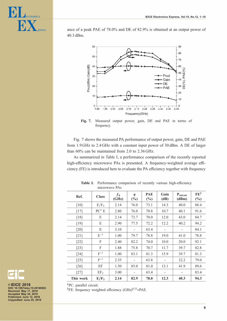
ance of a peak PAE of 78.0% and DE of 82.9% is obtained at an output power of
40.3 dBm.
Fig. 7 shows the measured PA performance of output power, gain, DE and PAE
from 1.9GHz to 2.4GHz with a constant input power of 30 dBm. A DE of larger
than 60% can be maintained from 2.0 to 2.36GHz.
As summarized in Table I, a performance comparison of the recently reported
high-efficiency microwave PAs is presented. A frequency-weighted average effi-
ciency (FE) is introduced here to evaluate the PA efficiency together with frequency
Fig. 7. Measured output power, gain, DE and PAE in terms offrequency.
Table I. Performance comparison of recently various high-efficiencymicrowave PAs
Ref. Classf0
(GHz)�
(%)PAE(%)
Gain(dB)
Pout,sat
(dBm)FE2
(%)
[10] E/F3 2.14 76.0 73.1 14.3 40.0 88.4
[17] PC1 E 2.80 76.0 70.8 10.7 40.1 91.6
[18] E 2.14 73.7 70.0 12.0 43.0 84.7
[19] E 2.90 77.5 72.2 12.2 40.2 94.2
[20] E 3.10 - 63.4 - - 84.1
[21] E−1 1.00 79.7 78.8 19.0 41.0 78.8
[22] F 2.40 82.2 74.0 10.0 20.0 92.1
[23] F 1.88 75.8 70.7 11.7 39.7 82.8
[24] F−1 1.00 83.1 81.3 15.9 39.7 81.3
[25] F−1 2.35 - 63.8 - 32.2 79.0
[26] EF 1.50 85.0 81.0 13.1 41.9 89.6
[27] EF3 3.00 - 63.4 - - 83.4
This work E/F3 2.14 82.9 78.0 12.3 40.3 94.3
1PC: parallel circuit.2FE: frequency weighted efficiency (GHz)0.25�PAE.
© IEICE 2018DOI: 10.1587/elex.15.20180503Received May 17, 2018Accepted May 24, 2018Publicized June 12, 2018Copyedited June 25, 2018
9
IEICE Electronics Express, Vol.15, No.12, 1–10
[28]. It is evident that the proposed PA products the highest FE among the
mentioned PAs because of its extended operating frequency and high efficiency.
5 Conclusion
In this paper, a transmission-line compensation circuit has been developed in order
to compensate the excess output capacitance and consequently extend the max-
imum operating frequency fmax of a class-E/F3 PA mode when keeping its optimal
mode of operation. Theoretical analysis has been presented so as to determine the
values of the required circuit elements in detail. Based on the methodology
developed in this paper, the proposed class-E/F3 PA has been designed, fabricated,
and measured. The high-performance results of the fabricated class-E/F3 PA have
been realized with the output power of 40.3 dBm, drain efficiency of 82.9% at the
operating frequency of 2.14GHz. In brief, due to its extended fmax, simple
construction and high performance, the class-E/F3 PA with TLCC is suitable for
use as a high efficiency PA operating in the microwave band.
Acknowledgments
This work was supported by the National Natural Science Foundation of China
under Grant 61501322.nts.
© IEICE 2018DOI: 10.1587/elex.15.20180503Received May 17, 2018Accepted May 24, 2018Publicized June 12, 2018Copyedited June 25, 2018
10
IEICE Electronics Express, Vol.15, No.12, 1–10
Related Documents


