Welcome message from author
This document is posted to help you gain knowledge. Please leave a comment to let me know what you think about it! Share it to your friends and learn new things together.
Transcript


13. C. Kim, and J. Kim, “Organic photovoltaic cell in lateral-tandem configuration employing continuously-tuned
microcavity sub-cells,” Opt. Express 16(24), 19987–19994 (2008).
14. B. O'Connor, K. H. An, K. P. Pipe, Y. Zhao, and M. Shtein, “Enhanced optical field intensity distribution in
organic photovoltaic devices using external coatings,” Appl. Phys. Lett. 89(23), 233502 (2006).
15. M. Agrawal, and P. Peumans, “Broadband optical absorption enhancement through coherent light trapping in
thin-film photovoltaic cells,” Opt. Express 16(8), 5385–5396 (2008).
16. H. Hoppe, and N. S. Sariciftci, “Organic solar cells: An overview,” J. Mater. Res. 19(7), 1924–1945 (2004).
17. M. M. Wienk, M. P. Struijk, and R. A. J. Janssen, “Low band gap polymer bulk heterojunction solar cells,”
Chem. Phys. Lett. 422(4-6), 488–491 (2006).
18. F. Yang, R. R. Lunt, and S. R. Forrest, “Simultaneous heterojunction organic solar cells with broad spectral
sensitivity,” Appl. Phys. Lett. 92(5), 053310 (2008).
19. E. Palik, Handbook of Optical Constants of Solids (Academic Press; 1st edition, 1985).
20. B. O'Connor, C. Haughn, K. H. An, K. P. Pipe, and M. Shtein, “Transparent and conductive electrodes based on
unpatterned, thin metal films,” Appl. Phys. Lett. 93(22), 223304 (2008).
21. G. Dennler, K. Forberich, M. C. Scharber, C. J. Brabec, I. Tomis, K. Hingerl, and T. Fromherz, “Angle depen-
dence of external and internal quantum efficiencies in bulk-heterojunction organic solar cells,” J. Appl. Phys.
102(5), 054516 (2007).
22. A. Meyer, and H. Ade, “The effect of angle of incidence on the optical field distribution within thin film organic
solar cells,” J. Appl. Phys. 106(11), 113101 (2009).
23. I. G. Hill, A. Kahn, Z. G. Soos, and R. A. Pascal, “Chem. “Charge-separation energy in films of pi-conjugated
organic molecules,” Chem. Phys. Lett. 327(3-4), 181–188 (2000).
24. M. C. Scharber, D. Mühlbacher, M. Koppe, P. Denk, C. Waldauf, A. J. Heeger, and C. J. Brabec, “Design rules
for donors in bulk-heterojunction solar cells – Towards 10% energy-conversion efficiency,” Adv. Mater. 18(6),
789–794 (2006).
25. The MatchWorks, Inc., Matlab R2009a (2009).
26. F. J. López-Hernández, R. Pérez-Jiménez, and A. Santamarı�a, “Ray-tracing algorithms for fast calculation of the
channel impulse response on diffuse IR wireless indoor channels,” Opt. Eng. 39, 2775–2780 (2000).
27. H. A. Macleod, Thin-film Optical Filters, 3rd Ed. (Taylor & Francis, 2001).
28. H. Hoppe, N. Arnold, N. S. Sariciftci, and D. Meissner, “Modeling the optical absorption within conjugated
polymer/fullerene-based bulk-heterojunction organic solar cells,” Sol. Energy Mater. Sol. Cells 80(1), 105–113
(2003).
29. A. Premoli, and M. L. Rastello, “Minimax refining of wide-band antireflection coatings for wide angular inci-
dence,” Appl. Opt. 33(10), 2018–2024 (1994).
30. D. P. Partlow, and T. W. O’Keeffe, “Thirty-seven layer optical filter from polymerized solgel solutions,” Appl.
Opt. 29(10), 1526–1529 (1990).
31. K. M. Ho, C. T. Chan, C. M. Soukoulis, R. Biswas, and M. Sigalas, “Photonic band gaps in three dimensions:
New layer-by-layer periodic structures,” Solid State Commun. 89(5), 413–416 (1994).
32. R. R. King, D. C. Law, K. M. Edmondson, C. M. Fetzer, G. S. Kinsey, H. Yoon, R. A. Sherif, and N. H. Karam,
“40% efficient metamorphic GaInP/GaInAs/Ge multijunction solar cells,” Appl. Phys. Lett. 90(18), 183516
(2007).
33. G. D. Wei, S. Y. Wang, K. Renshaw, M. E. Thompson, and S. R. Forrest, “Solution-processed squaraine bulk
heterojunction photovoltaic cells,” ACS Nano 4(4), 1927–1934 (2010).
1. Introduction: the fiber OPV tandem concept
Tandem solar cells combining absorbers with different bandgaps that cover complementary
parts of the solar spectrum reduce thermalization losses and increase the cell voltage [1,2].
Organic tandem solar cells have been considered in two main configurations (shown schemat-
ically in Fig. 1a,b) – transmissive and reflective [3–6]. In the more common transmissive con-
figuration, multiple sub-cells are stacked such that spectral components not absorbed by the
front cell are potentially absorbed by the back cell(s). The sub-cells are typically connected in
series, for example by placing a recombination electrode between them. In this configuration,
the layer thicknesses and compositions are optimized via optical and transport modeling [7,8],
subject to the restriction that the photocurrents from all sub-cells must be matched. This de-
sign has its origins in monolithic inorganic solar concentrator PV cells [32]. However, unlike
inorganic concentrator cells, organic solar cells that are aimed at low cost will likely not em-
ploy solar tracking. This restriction can be a limiting factor in terrestrial applications, where a
range of illumination angles and wavelengths can magnify resistive losses in a sub-cell. Alter-
natively, two sub-cells can be placed next to each other at an angle (forming a “V” profile),
such that incident light that is not absorbed by one sub-cell is reflected onto and potentially
captured by the apposing sub-cell. At very sharp V angles the incident light can be trapped
#127867 - $15.00 USD Received 6 May 2010; revised 17 Jun 2010; accepted 18 Aug 2010; published 7 Sep 2010(C) 2010 OSA 13 September 2010 / Vol. 18, No. 103 / OPTICS EXPRESS A433
efficiently [3]. However, this design is limited to two complementary sub-cells, and the inten-
sity distribution along the sub-cell length is highly uneven (particularly at sharp V angles).
Due to typical variations in the open circuit voltage (VOC) and fill factor (FF) of organic solar
cells with illumination intensity [7], this latter effect potentially makes it difficult to achieve
the optimal power point of the cell.
Here we propose a novel tandem solar cell architecture, illustrated schematically in Fig.
1(c), that is based on a collection of efficient narrow-band absorbing sub-cells whose cumula-
tive response can be made efficient over a broad incident spectrum by engineering efficient
reflection of off-resonance spectral components among the constituent sub-cells. Such an ar-
chitecture can be realized in the form of arrays of fiber-shaped solar cells that are distributed
throughout a volume. This arrangement can be achieved, for example, by 3-dimensional
weaving and/or by embedding solar cell fibers in a clear polymer matrix. We describe the
details of several promising arrangements and calculate their expected performance based on
experimentally validated optical and transport models of organic solar cells and optical coat-
ings. Realistic material combinations and geometries are predicted to yield performance sig-
nificantly exceeding the state-of-the-art in organic PV cells.
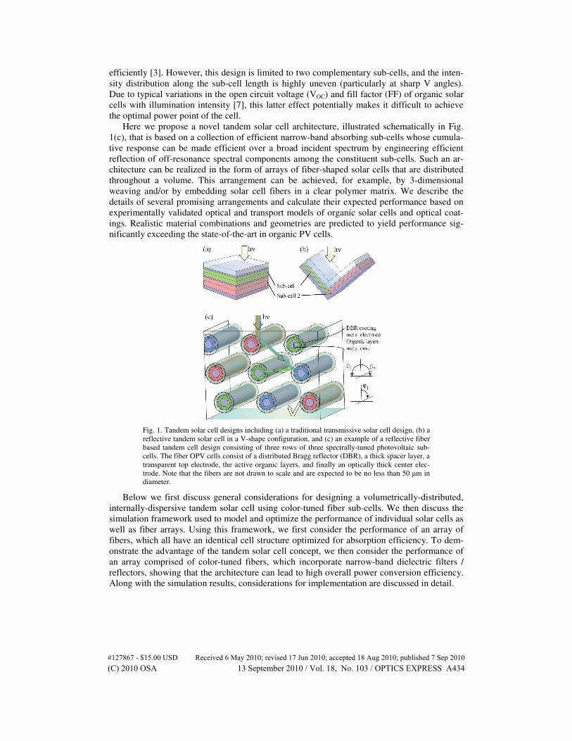
Fig. 1. Tandem solar cell designs including (a) a traditional transmissive solar cell design, (b) a
reflective tandem solar cell in a V-shape configuration, and (c) an example of a reflective fiber
based tandem cell design consisting of three rows of three spectrally-tuned photovoltaic sub-
cells. The fiber OPV cells consist of a distributed Bragg reflector (DBR), a thick spacer layer, a
transparent top electrode, the active organic layers, and finally an optically thick center elec-
trode. Note that the fibers are not drawn to scale and are expected to be no less than 50 µm in
diameter.
Below we first discuss general considerations for designing a volumetrically-distributed,
internally-dispersive tandem solar cell using color-tuned fiber sub-cells. We then discuss the
simulation framework used to model and optimize the performance of individual solar cells as
well as fiber arrays. Using this framework, we first consider the performance of an array of
fibers, which all have an identical cell structure optimized for absorption efficiency. To dem-
onstrate the advantage of the tandem solar cell concept, we then consider the performance of
an array comprised of color-tuned fibers, which incorporate narrow-band dielectric filters /
reflectors, showing that the architecture can lead to high overall power conversion efficiency.
Along with the simulation results, considerations for implementation are discussed in detail.
#127867 - $15.00 USD Received 6 May 2010; revised 17 Jun 2010; accepted 18 Aug 2010; published 7 Sep 2010(C) 2010 OSA 13 September 2010 / Vol. 18, No. 103 / OPTICS EXPRESS A434
2. Design of a fiber OPV cell to be used in a volumetrically distributed reflective tandem
Several variants of fiber based-PV cells have been demonstrated, in particular by using organ-
ic semiconductors which can be easily deposited on non-planar substrates [9–12]. Here, we
utilize a simple heterojunction OPV cell consisting of a metal-organic-metal layer sequence
that is deposited onto a fiber (Fig. 2b) rather than a planar (Fig. 2a) substrate [10]. Light enters
the device from the outside, opposite the substrate, unlike traditional OPV cells in which light
enters the device through the substrate (e.g. indium tin oxide coated glass). The motivation for
using a metal-organic-metal layer structure instead of a traditional configuration employing
ITO is two-fold: a) eliminating ITO potentially improves manufacturability, reliability and
cost-effectiveness, and b) it allows for a stronger optical microcavity that can be tuned to effi-
ciently absorb light over a narrower part of the spectrum [13–15]. The latter consideration will
be important in the overall design of the new tandem architecture.
The individual OPV cells considered here (Fig. 2e) consist of a semitransparent silver ca-
thode, an optical spacer (working simultaneously as a charge transport layer), an active ab-
sorbing layer, another optical spacer which doubles as an exciton blocking layer, an optically
thick silver electrode, and finally the fiber substrate (listed in the order of each layer’s position
in the path of incident light). Numerous commercially available organic dye molecules can be
identified to cover a 200 nm or greater band of the incident spectrum with a high coefficient
of absorption (i.e. >1.5x105 cm
−1) within a 300–1000 nm spectral range [7,16–18]. Thus, for
simplicity we assume a generic material for the absorber layer capable of absorbing over a
200 nm optical bandwidth between 300 and 1000 nm. The real part of the refractive index of
the absorber is set to n = 1.75, and the extinction coefficient is set to k = λα/4π over the 200
nm absorption band and k = 0 at all other wavelengths, where λ is the wavelength of light and
the absorption coefficient, η = 1.5x105 cm
−1. A nominal exciton diffusion length (LD) of 20
nm is also assumed for this layer [7]. The refractive index of the remainder of the cell includes
1.75 for the optical spacers and a wavelength-dependent value for silver taken from literature
[19]. The thickness of the semitransparent top electrode is set to 10 nm, and the thickness of
the back electrode is set to 100 nm. A 10 nm Ag film has been shown to have a sheet resis-
tance comparable to ITO making it a suitable alternative as a transparent conducting electrode
[20]. Finally, the thicknesses of the optical spacers and absorption layer are designed to max-
imize the short circuit current (jSC) of the individual OPV cell and are given below for specific
tandem designs.
3. Approach to modeling and optimization of individual fiber OPV cells and multi-fiber
arrays
The design and analysis of the fiber OPV cells uses optoelectronic models presented and vali-
dated in detail elsewhere [7,20]. Briefly, the model allows us to quantify the optical field in-
tensity distribution throughout the OPV cell using the transfer matrix approach [8]. From the
optical field intensity distribution, the exciton generation rate is calculated, and the exciton
diffusion equation is numerically solved to determine the external quantum efficiency (ηEQE).
The boundary conditions for the diffusion equation are: 1) complete exciton dissociation at the
boundary between the electron donor and acceptor layers (here, the absorber and front side
optical spacer), and 2) zero exciton diffusion at the opposite boundary (i.e. absorber / back
side optical spacer). Following exciton dissociation, 100% charge collection efficiency at the
electrodes is assumed [7]. A qualitative view of a flat-band energy level structure for this cell
configuration is given in Fig. 2e. The jSC is then predicted by integrating the product of ηEQE
and incident photon flux over the solar spectrum (AM1.5G, truncated between 300 and 1000
nm).
#127867 - $15.00 USD Received 6 May 2010; revised 17 Jun 2010; accepted 18 Aug 2010; published 7 Sep 2010(C) 2010 OSA 13 September 2010 / Vol. 18, No. 103 / OPTICS EXPRESS A435

Fig. 2. Device structures modeled for a single solar cell design: (a) planar metal-organic-metal
solar cell, (b) fiber OPV cell geometry, (c) row of fibers, and (d) matrix of fiber cells. (e) Qua-
litative view of the energy band structure for the solar cell in all configurations.
To model the OPV cell on a fiber substrate, we consider it to be a collection of vanishingly
small planar cells tangentially distributed along the circumference of the fiber, each having
light rays incident at an arbitrary angle throughout a 180-degree range. This approach has
been used to accurately model organic solar cells in many studies, including those that consid-
er the dependence on illumination angle [21,22]. Other key parameters of OPV cell perfor-
mance include the fill factor (FF), and open circuit voltage (VOC). The VOC of each cell is set
to be 0.4 V less than the potential given by the optical bandgap (roughly the HOMO-LUMO
gap) of the absorbing material [13,23]. The FF is assumed to be 0.7, a value that is observed
in high performance OPV cells [24].
To evaluate multi-fiber OPV systems, the model embodying an individual fiber OPV cell
is combined with numerical ray-tracing. A multi-fiber unit cell is first constructed in which
each fiber is assumed to be infinitely long. The location of each fiber within the unit cell is
specified, and periodic boundary conditions are applied in the direction normal to the fiber
axis, such that the array extends “horizontally”. A line emitter, defined above the fiber system
emits light rays towards the fiber bundle. A retro-reflector (with reflectivity = 1) is placed
below the fiber bundle. In Fig. 3, a random sample of rays are traced for a two-row fiber OPV
matrix [25]. In this simulation, rays incident on the left or right edge of the unit cell are trans-
lated to the opposite edge in order to satisfy the periodic boundary condition. On average the
rays strike all surfaces of each fiber, suggesting that shading losses can be neglected [10]. This
ray-tracing routine is carried out until the summed intensity of the rays remaining in the array
is less than 0.5% of the input intensity. For the line emitter, 10,000 rays are generated (20,000
rays in the case of bundles with 20 rows of fiber cells) and randomly placed along the length
of the emitter with even probability [26], resulting in a standard deviation of the predicted jSC
for repeated simulations of the larger bundles of less than 0.094 mA/cm2 (based on the area
occupied by the entire array – i.e. “real estate” of the module).
#127867 - $15.00 USD Received 6 May 2010; revised 17 Jun 2010; accepted 18 Aug 2010; published 7 Sep 2010(C) 2010 OSA 13 September 2010 / Vol. 18, No. 103 / OPTICS EXPRESS A436

Fig. 3. Output of the ray-tracing program that is used to analyze periodic multi-fiber OPV sys-
tems. Sample rays are traced to visually inspect the performance of the bundled fiber OPV sys-
tem. Rays that leave the system are shown in green, and rays from the emitter and those that are
incident on at least two bodies are shown in blue.
A key aspect of the multi-fiber tandem design is that those incident wavelengths that are
not efficiently harvested by a given fiber are efficiently reflected. An appropriately tuned met-
al-organic-metal cavity reflects a large portion of the off-resonant light. However, due to the
large number of reflections experienced by a light ray on average, even a small amount of
parasitic absorption in the outer electrode for a single pass can escalate to a substantial loss
overall. Therefore, we further improve off-resonant reflectivity by applying dielectric coatings
around the OPV fiber. A 30-layer dielectric coating is applied to the color-tuned OPV cells
with an initial design based on multiple quarter wave stacks of 5-10 layers, forming a band
pass filter. Each quarter wave stack gives rise to regions of high reflectivity near its characte-
ristic wavelength; combining several such stacks forms regions of high reflectivity for spectral
components that are off-resonance with the fiber cell’s peak absorption. The initial coating
configuration is refined by varying the individual layer thicknesses in an iterative process to
maximize both transmission on-resonance and reflectivity off-resonance for a planar cell un-
der normal illumination [15,27]. The coatings are applied around the fiber OPV cell on top of
a thick (greater than 100 nm) transparent coating that reduces light coherence to minimize
parasitic interference effects [28]. The coatings consist of two alternating materials having
refractive indices of nH = 2.2 and nL = 1.35, these values being common in optical coating
design [27]. For simplicity, the refractive indices of both the thick transparent (e.g. barrier)
coating between the outer electrode and the DBR stack, as well as the clear matrix surround-
ing the coated fibers, are assumed to be the same as air (i.e. n = 1). This assumption is made
based on the likelihood that the fiber array will be embedded in a clear polymer or glass ma-
trix that has an index nearly identical to that of a typical barrier material (e.g. n = 1.4), leading
to a conserved diffraction angle. Using n = 1 instead also conserves the diffraction angle but
simplifies the model. An anti-reflection coating (ARC) at the surface of the clear matrix hold-
ing the fibers will minimize any differences associated with moving away from the n = 1 as-
sumption. ARCs on glass have been designed with reflectivity below 1% over the visible
spectrum and for a large range of incident angles [29]. In addition, while a host matrix with n
= 1.4 would require a DBR redesign, this refractive index falls between the values for the
#127867 - $15.00 USD Received 6 May 2010; revised 17 Jun 2010; accepted 18 Aug 2010; published 7 Sep 2010(C) 2010 OSA 13 September 2010 / Vol. 18, No. 103 / OPTICS EXPRESS A437
DBR coating materials, reducing the optical impedance and improving the coating’s perfor-
mance.
In the next two sections we apply this architecture and modeling approach to multi-fiber
OPV cell arrays. We first consider the performance of arrays using only one OPV cell struc-
ture. Subsequently, multiple, spectrally tuned OPV cells are employed within the fiber matrix
to maximize performance across the incident solar spectrum.
4. Design of multi-fiber OPV arrays
To investigate the performance of the volumetrically distributed, reflective tandem PV cell
architecture, we begin by considering a single OPV cell in a planar configuration, then map its
performance onto a single fiber; we then consider adjacent fibers, and finally multiple rows of
fibers, as illustrated in Fig. 2.
Single-fiber architecture: We first examine an OPV cell with a single absorption layer
capturing 500-700 nm light. Over this wavelength range, the power conversion efficiency is
maximized by calculating the trade-off between current (limited by the solar photon flux den-
sity at each wavelength) and VOC (defined as a constant that depends only on the chosen opti-
cal band gap of the absorption layer). Using the modeling described above, we find that the
planar OPV cell structure resonant with the 500-700 nm band of incident light which max-
imizes jSC consists of a 10 nm Ag electrode followed by a 52 nm optical spacer, 15 nm absorp-
tion layer, 52 nm exciton blocking layer, and finally a 100 nm Ag back contact. For this de-
vice, an optical bandpass filter is not yet applied. Under AM1.5G illumination, the OPV cell is
predicted to have a short circuit current, jSC = 8.2 mA/cm2. Combining this with a FF = 0.7,
and a VOC determined to be 1.37 V results in a power conversion efficiency, η = 7.86%. Ap-
plying this structure to a fiber geometry results in a jSC = 7.8 mA/cm2; the reduction in jSC
relative to the planar analogue is due to increased reflection at oblique incident angles on the
fiber surface. For comparison a planar OPV cell with a 200 nm ITO electrode with optimized
layer thicknesses is predicted to have jSC = 6.9 mA/cm2 and η = 6.6%.
Planar array of fibers: To capture a portion of the reflected light, the fibers can be placed
adjacent to one another, as might be encountered in a woven textile. A planar array of infinite-
ly long fibers is illustrated in Fig. 2c; based on the ray-tracing model described above, this
array is predicted to have a jSC = 8.9 mA/cm2, overcoming the losses associated with the fiber
geometry under normal illumination, and outperforming the planar cell. (Note that in one as-
pect, the linear fiber array is similar to the V-shaped reflective tandem OPV cell discussed
earlier.)
While a single row of fibers can increase the photocurrent substantially (~14% over a sin-
gle fiber OPV cell, and 8.5% over a planar cell), much of the light initially reflected off the
fiber surface is not trapped. In appropriately configured multi-row (3-dimensionally distri-
buted) fiber OPV bundles decribed below, however, a majority of light rays that enter the fi-
ber matrix bounce between the constituent fibers many times.
Volumetric array of fibers: We now consider multi-row fiber arrays, varying the depth
from 1 to 20 rows. Due to improved packing, performance predicted by ray tracing models
was generally best for fibers that were placed in a repeating “slant” arrangement (see Fig. 4)
over that of a V- or W-shaped arrangement. For each set of rows, the distance between fibers
in a slant arrangement was varied spatially both vertically and horizontally to maximize jSC.
The geometries of the best-performing bundles for 1, 2, 3 and 10 rows are shown in Fig. 4,
with their calculated jSC plotted in Fig. 5. For the 10-row system we observe a 36% improve-
ment over the single fiber cell. As expected, there are diminishing returns with an increasing
number of rows; at 10 rows, absorption of light over the wavelength range corresponding to
the spectrum of the absorption layer exceeds 90%.
#127867 - $15.00 USD Received 6 May 2010; revised 17 Jun 2010; accepted 18 Aug 2010; published 7 Sep 2010(C) 2010 OSA 13 September 2010 / Vol. 18, No. 103 / OPTICS EXPRESS A438

Fig. 4. (a-d) 2-dimensional coordinates for the best-performing fiber-OPV bundles for 1, 2, 3,
and 10-row systems. These geometries are determined through a non-exhaustive search and
further optimization is likely possible. The coordinates are given in units of fiber diameters.
Superimposed on the calculated photocurrent for fiber-based devices in Fig. 5 is the pho-
tocurrent of the widely studied planar heterojunction copper phthalocyanine (CuPc) - C60 cell
having a thin semitransparent Ag metal electrode. The device structure consists of 10 nm Ag,
10 nm bathocuproine (BCP), 30 nm C60, 25 nm CuPc, 8 nm MoO3, and 100 nm Ag. The exci-
ton diffusion length was set to 8 nm in CuPc and 20 nm in C60, values in agreement with those
measured in literature [20]. The device model used here has been shown to accurately predict
the performance of this planar heterojunction PV cell [7,20]. Comparatively, this small-
molecule OPV cell and the simplified cell initially described are similarly designed with metal
electrodes and optical spacers sandwiching the absorption layer(s). The cavities in both cells
are tuned for optimal photocurrent generation over a similar bandwidth, and with multiple
fiber rows the incident light absorption is maximized. Consequently, the performance between
the small molecule planar heterojunction and the simplified single cell design compare well,
suggesting the simplified fiber design is a valid estimate of expected OPV performance.
5. Using multiple color-tuned fiber OPV cells to build an efficient broad-band array
Further increases in the efficiency of multi-fiber OPV cells can be realized by combining
spectrally-tuned fiber devices in volumetric arrays. The individual OPV cells on fibers retain
the same basic structure (i.e. metal-organic-metal), but the thicknesses of the absorber and
other layers are modified to tune the optical microcavity and maximize the photocurrent of an
individual fiber device over a specific spectral band [13]. Furthermore, a band-pass optical
filter is added (as discussed in Section 3) to efficiently reflect off-resonant wavelengths while
remaining transparent for on-resonance wavelengths. These coatings are uniquely designed
for each type of spectrally tuned OPV-cell. The fiber arrays incorporate wavelength selective
dispersion by virtue of their geometry and the DBR coating, such that incident light is effec-
tively sorted among the sub-cells – a ray of particular wavelength bounces between the consti-
tuent fibers until it encounters (and is absorbed by) a complementary tuned fiber OPV cell.
#127867 - $15.00 USD Received 6 May 2010; revised 17 Jun 2010; accepted 18 Aug 2010; published 7 Sep 2010(C) 2010 OSA 13 September 2010 / Vol. 18, No. 103 / OPTICS EXPRESS A439

Fig. 5. (a) Predicted short circuit current for the fiber bundles ranging from a single fiber, to a
fiber system consisting of 20 rows. Coordinates for the 1, 2, 3 and 10 row systems are given in
Fig. 4. The number of sub-cells is varied from 1 to 4 designs with details of these designs pro-
vided in Table 1. Results for a similar OPV cell based on a planar heterojunction structure with
CuPc and C60 as the donor-acceptor materials are shown for comparison.
Table 1. Optical absorption band, expected VOC, and device structure of the fiber sub-
cells used in the multi-fiber tandem OPV cells modeled in Fig. 4a
No. Sub-cell Absorption band, nm VOC, V tSpacer, nm tAbs, nm
1 i 500 – 700 1.37 52 15
2 i 450 – 650 1.51 44 15
ii 650 – 850 1.06 72.5 10
3 i 350 – 550 1.86 31 12.5
ii 550 - 750 1.25 55 12.5
iii 750 - 950 0.91 87.5 10
4 i 300 - 500 2.08 25 15
ii 365 - 665 1.47 45 15
iii 630 - 830 1.09 70 12.5
iv 800 - 1000 0.84 92.5 10 aThe Number column indicates the number of sub-cells for the fiber bundles, the optical spacers above and below the
absorption layer are set to the same thickness (tSpacer) for design simplicity, and tAbs is the thickness of the absorption
layer.
The predicted jSC of fiber bundles that combine 1, 2, 3, or 4 types of fibers (i.e.
representing 1, 2, 3, or 4 complementary optical bands) is shown in Fig. 5, which also depicts
the performance of arrays whose depths range from 1 to 20 rows of fibers. As previously men-
tioned, each fiber PV cell is optimized to have high efficiency over a 200 nm spectral band,
with the target spectral band and layer thicknesses of the sub-cells for the range of fiber types
provided in Table 1. The fiber spatial orientation is the same as the single cell designs (given
in Fig. 4) while the color-tuned cell placement is varied within the fiber matrix to maximize
performance. A complete optimization of color-tuned cell placement was not performed;
however, the best performance was generally observed when the color-tuned cells were simi-
lar in number and evenly spaced. For the multi-color fiber systems, light trapping is slightly
reduced due to the increased number of reflections before capture, yet there is a substantial
gain in the spectral band of light capture. The color-tuned external quantum efficiency of the
individual planar cells, along with the external quantum efficiencies of a 10-row, 4-color fiber
system are given in Fig. 6a and Fig. 6b, respectively. The reflectivity of the sub-cell tuned
between 630 and 830 nm is also provided as an example of performance typical for the filter-
#127867 - $15.00 USD Received 6 May 2010; revised 17 Jun 2010; accepted 18 Aug 2010; published 7 Sep 2010(C) 2010 OSA 13 September 2010 / Vol. 18, No. 103 / OPTICS EXPRESS A440

OPV cell designs with high off-resonance reflectivity and high on-resonance absorption. Un-
der the assumption that the absorber layer only absorbs over a 200 nm bandwidth, the micro-
cavity OPV cells will inherently have a high degree of reflectivity off-resonance. However,
the filters are important in mitigating the off-resonant parasitic absorption generally observed
in the layers of the OPV cells.
Fig. 6. Performance parameters for the 10-row, 4 color-tuned OPV fiber bundle. (a) External
quantum efficiencies (EQEs) of the planar counterparts of the 4 microcavity tuned fiber OPV
cells under normal illuminations. The reflectivity of one of the cells is also given to illustrate
the high reflectivity for off-resonant wavelengths. (b) Total EQE along with the contributions
of the separate color-tuned fibers in the 10-row, 4 color-tuned bundle. Predicted open circuit
voltage is also given for each sub-cell.
The foregoing analysis predicts the array photocurrent. To predict the power conversion
efficiency, we place the individual fiber cells in electrical series and/or parallel to match cur-
rent and voltage and maximize power conversion efficiency. The vertical distribution of fibers
will see varying intensity and thus each fiber in depth will have a unique maximum power
point. However, we expect that the fiber with the same relative coordinate in adjacent unit
cells will have the same current-voltage output. These cells can be added in parallel to sum the
current without voltage losses. As the external wiring runs down the composite, when current
is matched between the multi-cell parallel wiring, the circuit can be combined in series to sum
voltage without current losses. This provides a means to sum power output from each fiber
without significant losses. The open circuit voltage of each 4 sub-cell design is given in Fig.
6b, and as stated above the fill factor is assumed to be 0.7. Under these assumptions, the pow-
er conversion efficiency of the 4 color-tuned sub cell 10-row design is predicted to be 17.0%.
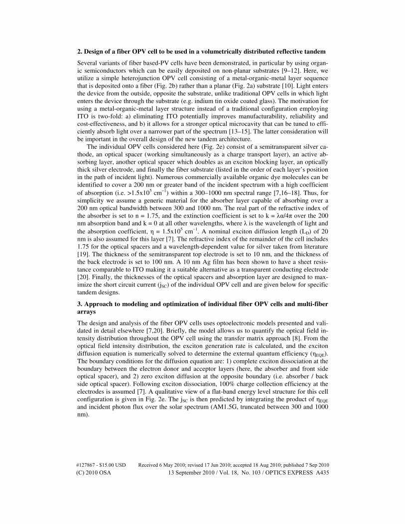
Performance at different angles of illumination: It is also important to consider the per-
formance of these new reflective / inherently dispersive tandem architectures with illumina-
tion angle, as shown in Fig. 7. Here we examine the responsivity of a planar microcavity OPV
cell tuned between 500 and 700 nm, and of a 2-row fiber bundle having the same type of OPV
structure. It is observed that at low off-normal incident angles (relative to the plane of the fi-
ber array), the reponsivity is similar; however, at very large incident angles the bundle system
outperforms its planar counterpart. Also shown in Fig. 7 is the performance of the 10-row, 3-
color tuned fiber OPV bundle. For this system, the specific symmetry of the “repeat unit” of
the bundle results in a non-trivial dependence of efficiency on the 3-primary incident angle
vectors. The results also indicate that while the 3-row bundle performance for a wide range of
longitudinal incident angles (φ) is similar to that of the 2-row bundle, increasing the other
incident angles results in a faster roll-off in efficiency. This highlights the importance of the
interplay of illumination angle and array symmetry in the overall system design and optimiza-
tion.
#127867 - $15.00 USD Received 6 May 2010; revised 17 Jun 2010; accepted 18 Aug 2010; published 7 Sep 2010(C) 2010 OSA 13 September 2010 / Vol. 18, No. 103 / OPTICS EXPRESS A441
Fig. 7. The angular dependence of a planar metal-organic-metal OPV device and a 2-row fiber
bundle having the same cell design. Also plotted is the performance of the 10-row, 3 color-
tuned fiber bundle with the layout given in Fig. 4. The variation in the incident angle for the
bundle is illustrated in Fig. 1c. The 10-row fiber bundle is asymmetric and the performance is
therefore given for 3-angle variations. The relative responsivity is a measure of performance
assuming the intensity on the top surface of the solar cell is constant with angle.
6. Considerations for implementation
Components of the proposed tandem architecture have been previously demonstrated. For
example, individual fiber-based solar cells based on organic [10] and inorganic [9] materials
have been reported. Methods exist to form DBR coatings on a variety of substrates by sputter-
ing, thermal evaporation, solution coating, and other means [27,30]. Fabrication of 3-
dimensional arrays of fiber- or rod-based solar cells could proceed by 3-D weaving, scaffold-
ing [31], and monolithically embedding in transparent media. Bus-lines will be required to
transport charge efficiently down long lengths of fiber. The bus-lines can be placed as metal
strips underneath each fiber and will also act as light scattering sources. In the models, the
fiber bundles are observed to be insensitive to exact fiber placement, such as vertical spacing
between rows, suggesting that the implementation of bus-lines will not substantially alter de-
vice performance.
While the use of coated fiber bundles increases the total solar cell surface area and conse-
quently the amount of organic, dielectric, and metal materials used beyond that of a planar cell
occupying equivalent real estate, employing low-cost materials (e.g. organic absorbers and
thin metal electrodes) can be effective. Furthermore, we anticipate the operational lifetime of
the PV cells will be improved due to multiple levels of encapsulation (e.g. barrier coating,
DBR stack, and clear matrix in which the fibers are embedded). We note, however, that the
illumination intensity per surface area of the thin-film solar cell will be lower, potentially af-
fecting device performance. A 1-row deep array of fibers has about 3 times more surface area
than its planar counterpart of the same real estate. The 10-row deep fiber design of Fig. 5 has
approximately 14 times more surface area. In a simple analysis, the surface of a given fiber
sees 1/14-sun AM1.5 illumination intensity. For organic solar cells, the VOC typically drops
with illumination intensity while the FF often increases and the overall power conversion effi-
ciency is not necessarily optimal at 1-sun [5,7,33]. How these parameters depend on illumina-
tion intensity depends substantially on the material and OPV cell design at hand, and in some
instances optimal conversion efficiency occurs at low (e.g. less than 1/20th sun [33]) intensity.
This suggests that the individual OPV cells can continue to perform efficiently, particularly
when considering the wavelength distribution of light transmitted through the DBR coating.
For example, for a 3-color tuned OPV cell bundle, the increase in surface area for the relevant
spectral band is reduced by a factor of 3 relative to total active surface area. Taking this into
#127867 - $15.00 USD Received 6 May 2010; revised 17 Jun 2010; accepted 18 Aug 2010; published 7 Sep 2010(C) 2010 OSA 13 September 2010 / Vol. 18, No. 103 / OPTICS EXPRESS A442

consideration, the 10-row bundle will see a reduced intensity per unit surface area of approx-
imately 3/14 or 20% of an equivalent planar cell.
7. Summary and Outlook
An individual fiber OPV cell has been shown to be less efficient than its planar counterpart.
However, simply placing multiple fibers adjacent to one another overcomes the losses through
improved light trapping. Placing the fiber cells in a 3-dimensionally distributed bundle confi-
guration leads to further enhancements in light trapping, resulting in an external quantum effi-
ciency that approaches the internal quantum efficiency. By adding sub-cells that are tuned to
efficiently convert light over a specific portion of the solar spectrum, the fiber system that
efficiently traps light also acts as a built-in dispersion element, matching incident wavelengths
of light to a complementary OPV cell. By virtue of optical microcavity design utilizing metal-
lic electrodes and dielectric coatings, the opposing requirements of electrode transparency and
conductivity can be decoupled to an extent. Here we have used a combination of optical and
transport models to show that color-tuned OPV cells in a fiber matrix can lead to power con-
version efficiencies over 17%, assuming modest absorption coefficients, metallic electrodes,
and conservative assumptions regarding the fill factor. Through improved light trapping,
broadband sensitivity, and output voltage optimization, this efficiency can be doubled over
what is predicted for an optimized single junction cell having similar intrinsic properties. Ad-
ditionally, improvements in the performance of single junction OPV cells will lead to im-
proved performance of the fiber OPV tandem design. The full design space for this tandem
architecture has not been exhausted in this study, and we expect that for color-tuned fiber
OPV bundles a more complete and coupled optimization of cell design and fiber placement
will lead to even further improvements in performance.
OPV device designs based on spatially distributed fibers offer several potentially powerful
advantages over conventional planar devices. For example, electrical interconnections can be
made with much greater latitude for current and voltage matching, in contrast to series-
connected tandem cells. Furthermore, spatially distributed fibers can be placed into an inert
matrix material that prevents the diffusion of oxygen and moisture, and offers considerable
protection from mechanical damage.
Finally, the overall concept of a reflective, inherently dispersive tandem architecture in-
volving volumetrically distributed sub-cells potentially can be applied to other sub-cell shapes
and material systems, including inorganic PV cells, and/or combinations of organic and inor-
ganic sub-cells.
Acknowledgments
We acknowledge the Air Force Office of Scientific Research (AFOSR) for their financial
support of this work (grant no. FA9550-09-1-0109).
#127867 - $15.00 USD Received 6 May 2010; revised 17 Jun 2010; accepted 18 Aug 2010; published 7 Sep 2010(C) 2010 OSA 13 September 2010 / Vol. 18, No. 103 / OPTICS EXPRESS A443
Related Documents