LICENSING REPORT on The HI-STORE CIS FACILITY by Holtec International Holtec Center One Holtec Drive Marlton, NJ 08053, USA (holtecinternational.com) USNRC Docket # 72-1051 Holtec Project 5025 Holtec Report # HI-2167374 Safety Category: Safety Significant NOTICE OF PROPRIETARY & COPYRIGHTED STATUS This document is a copyrighted intellectual property of Holtec International. All rights reserved. Proprietary information in this document is highlighted by gray shading. Excerpting any part of this document, except for public domain citations included herein, by any person or entity except the USNRC, a Holtec User Group (HUG) member company, or a foreign regulatory authority with jurisdiction over a Holtec owned or a Holtec client owned nuclear facility without an unambiguous written consent from Holtec International is unlawful. ATTACHMENT 3 TO HOLTEC LETTER 5025025 Page 1 of 604 Revision 0C May 2018

Welcome message from author
This document is posted to help you gain knowledge. Please leave a comment to let me know what you think about it! Share it to your friends and learn new things together.
Transcript
LICENSING REPORT
on
The HI-STORE CIS FACILITY
by
Holtec International
Holtec Center
One Holtec Drive
Marlton, NJ 08053, USA
(holtecinternational.com)
USNRC Docket # 72-1051
Holtec Project 5025
Holtec Report # HI-2167374
Safety Category: Safety Significant
NOTICE OF PROPRIETARY & COPYRIGHTED STATUS
This document is a copyrighted intellectual property of Holtec International. All rights reserved.
Proprietary information in this document is highlighted by gray shading. Excerpting any part of
this document, except for public domain citations included herein, by any person or entity except
the USNRC, a Holtec User Group (HUG) member company, or a foreign regulatory authority
with jurisdiction over a Holtec owned or a Holtec client owned nuclear facility without an
unambiguous written consent from Holtec International is unlawful.
ATTACHMENT 3 TO HOLTEC LETTER 5025025
Page 1 of 604 Revision 0C May 2018
HOLTEC INTERNATIONAL COPYRIGHTED MATERIAL
Report No. HI-2167374 Proposed Rev. 0A
i
GLOSSARY OF TERMS USED IN HI-STORE CIS FACILITY
LICENSING REPORT
Accident Condition Storage Temperature is the maximum 24 hour- average of the ambient
temperature at an ISFSI site. The accident condition temperature serves as the input air
temperature for a cask system to compute the accident condition peak cladding temperature for
which a regulatory limit is specified in ISG11 Rev 3.
AFR is an acronym for Away from Reactor storage.
Aging Management Program (AMP), outlined in Chapter 18, is a carefully crafted collection
of processes and procedures deemed to be necessary for an effective monitoring, inspection,
testing and recovery/remediation plan for the ISFSI to ensure safe operation for its entire Service
life.
ALARA is an acronym for As Low- As –Reasonably- Achievable
Ambient Temperature for Short Term Operations (operations involving use of a transport cask,
a Lifting device and/ or a on-site transport device) is defined as the 24 hour average of the local
temperature as forecast by the National Weather Service.
Ancillary or Ancillary Equipment is the generic name of a device used to carry out “Short
Term Operations.
BWR is an acronym for Boiling Water Reactor.
Canister means an all-welded vessel containing used fuel that has been qualified to serve as a
confinement boundary under the rules of 10CFR 72. The terms MPC, DSC, etc., are also used to
indicate a seal-welded spent fuel canister.
Canister Transfer Facility (CTF) is a below-grade placement location where the transport cask
is temporarily placed to effectuate vertical canister transfer between the transport cask and the
HI-TRAC CS.
Canister Transfer means transfer operations necessary to translocate a loaded canister between
a transport cask, HI-TRAC CS and/or the HI-STORM UMAX storage system.
Cask Crane is the gantry crane installed in the Cask Transfer Building for heavy load handling
activities
Cask Receiving Area is the physical location where loaded casks are received. Consists of a
vehicle entrance, vehicle parking area, VCT access port, cask and cask appurtenance lifting
apparatus, cask tilting apparatus, location for storage of cask transport appurtenances (e.g.,
personnel barrier, impact limiters, etc.), location for cask lid removal and installation, location
for transfer of the cask to the VCT, cask inspection and work area. The cask receiving area may
be partially or completely enclosed.
Cask Transfer Building (CTB) means the sheet metal enclosure that houses the Canister
Transfer Facility (CTF) and the cask receiving area and provides storage space for ancillary
equipment used in short term operations.
ATTACHMENT 3 TO HOLTEC LETTER 5025025
Page 2 of 604 Revision 0C May 2018
HOLTEC INTERNATIONAL COPYRIGHTED MATERIAL
Report No. HI-2167374 Proposed Rev. 0A
ii
Cavity Enclosure Container (CEC) means a thick-walled cylindrical steel weldment that
defines the storage cavity in HI-STORM UMAX for the storage of the canister.
CG is an acronym for the center- of- gravity.
Closure Lid means the METCON lid that is installed on the CEC to provide physical and
shielding protection to the stored canister.
Commercial Spent Fuel (CSF) refers to nuclear fuel used to produce energy in a commercial
nuclear power plant.
Confinement Boundary means the outline formed by the cylindrical enclosure of the canister
shell welded to a solid baseplate, and at least one top lid to create a hermetically sealed
enclosure.
Confinement System means the canister which encloses and confines the spent nuclear fuel
during storage.
Container Flange means the ring flange that is welded to the upper extremity of the Container
Shell.
Container Shell means the cylindrical portion of the Cavity Enclosure Container
Controlled Area means that area immediately surrounding the ISFSI over which the HI-STORE
Facility owner (Holtec) exercises authority over its use and within which all Short Term
Operations are performed.
Controlled Low-Strength Material (CLSM) is a self-compacted, cementitious material used
primarily as a backfill in place of compacted fill. Many terms are currently used to describe this
material, such as flowable fill, unshrinkable fill, controlled density fill, flowable mortar, flowable
fly ash, fly ash slurry, plastic soil-cement and soil-cement slurry (ACI 229R-99). CLSM and lean
concrete are also referred to as “Self-hardening Engineered Subgrade (SES)”
Cooling Time (or post-irradiation cooling time) for a spent fuel assembly is the time elapsed
after its discharge from the reactor to the time it is loaded into the canister.
Critical Characteristic means a feature of a SSC that is necessary for the proper safety function
of the SSC. Critical characteristics of a material are those attributes that have been identified, in
the associated material specification, as necessary to render the material’s intended function.
Design Basis Earthquake (DBE) is the seismic input applicable to the cask’s long term storage
on the ISFSI pad.
Design Basis Load (DBL) is a loading defined in this SAR to bound one or more events that are
applicable to the storage system during its service life. Thus, the snow pressure loading on the
cask’s lid specified in this SAR is a DBL because it is set substantially above the pressure from
accumulated snow set down in the national consensus standard for the 48 contiguous United
States.
Design Basis Missile (DBM) is the applicable missiles used to evaluate the safety of the storage
system
ATTACHMENT 3 TO HOLTEC LETTER 5025025
Page 3 of 604 Revision 0C May 2018
HOLTEC INTERNATIONAL COPYRIGHTED MATERIAL
Report No. HI-2167374 Proposed Rev. 0A
iii
Design Extended Condition Earthquake (DECE) is a beyond design basis seismic input that
exceeds the 10,000 year return earthquake at the site.
Design Heat Load or Design Basis Heat Load is the computed heat rejection capacity of the
HI-STORM system with a certified canister loaded with CSF stored in uniform storage with the
ambient at the normal temperature and the peak cladding temperature (PCT) at 400ºC. The
Design Heat Load is less than the thermal capacity of the system by a suitable margin that
reflects the conservatism in the system thermal analysis..
Design Life is the minimum duration for which the SSC or Facility is engineered to perform its
intended function set forth in this SAR, if operated and maintained in accordance with this
document.
Design Report is a document prepared, reviewed and QA validated in accordance with the
provisions of 10CFR72 Subpart G. The Design Report shall demonstrate compliance with the
requirements set forth in the Design Specification. A Design Report is mandatory for systems,
structures, and components (SCCs) designated as Important to Safety. This SAR serves as the
Design Report for the HI-STORE Facility.
Design Specification is a document prepared in accordance with the quality assurance
requirements of 10CFR72 Subpart G to provide a complete set of design criteria and functional
requirements for a system, structure, or component or Facility intended to be used in the
operation, of the HI-STORE CIS Facility. This document serves as the Design Specification for
the HI-STORE CIS Facility.
Divider Shell means a cylindrical shell bearing insulation over most of its inner or outer surface
that divides the annular space between the canister and the CEC shell into two discrete regions
for down- flow and up-flow of air in the HI-STORM UMAX VVM.
Dry Cask Storage System (DCSS) is a system that stores spent fuel or high level waste in a dry
condition.
Enclosure Vessel means the pressure vessel defined by the cylindrical shell, baseplate, top lid
and associated welds that provides confinement for the helium gas contained within the canister.
The Enclosure Vessel (EV) and the fuel basket together constitute the canister.
Equivalent (or Equal) Material is a material with critical characteristics (see definition above)
that meet or exceed those specified for the designated material.
Facility is used as an abbreviated name for the HI-STORE Consolidated Interim Storage facility
Fracture Toughness is a property which is a measure of the ability of a material to limit crack
propagation under a suddenly applied load.
FSAR is an acronym for Final Safety Analysis Report (10CFR72).
Fuel Basket means a honeycombed structural weldment with square openings which can accept
a fuel assembly of the type for which it is designed.
Gantry Crane is the device used in conjunction with special lifting devices that perform
elements of the cask lifting operations in the Cask Receiving Area.
ATTACHMENT 3 TO HOLTEC LETTER 5025025
Page 4 of 604 Revision 0C May 2018
HOLTEC INTERNATIONAL COPYRIGHTED MATERIAL
Report No. HI-2167374 Proposed Rev. 0A
iv
High Burnup Fuel (HBF) refers to fuel with a burnup greater than 45,000 MWD/MTU
HI-STORE or HI-STORE CIS is the consolidated interim storage facility envisaged to be built
and operated in Southeastern New Mexico.
HI-STORM VVM means the vertical ventilated module wherein the canister is stored in the
upright orientation.
HI-STORM UMAX System consists of loaded canisters stored in the HI-STORM UMAX
VVM under Docket Number 72-1040.
HI-STORM 100 System consists of any loaded canister model placed within any design variant
of the HI-STORM overpack in Docket Number 72-1014.
HI-STORM FW System is the larger capacity, variable height counterpart of the HI-STORM
100 system certified in Docket Number 72-1032
HI-TRAC CS is the shielded transfer cask used for performing canister transfer between the
transport cask and the HI-STORM UMAX system at HI-STORE.
HoltiteTM is the trademarked name of a family of neutron shield materials owned by Holtec
International.
HP is an acronym for Health Physics
HS is an acronym for HI-STORE Specific, used in relation to the ancillaries at the facility.
Important to Safety (ITS) means a SSC function or condition required to store spent nuclear
fuel safely; to prevent damage to spent nuclear fuel during handling and storage, and to provide
reasonable assurance that spent nuclear fuel can be received, handled, packaged, stored, and
retrieved without undue risk to the health and safety of the public.
Independent Spent Fuel Storage Installation (ISFSI) means a facility designed, constructed,
and licensed for the interim storage of spent nuclear fuel and other radioactive materials
associated with spent fuel storage in accordance with 10CFR72. An ISFSI may be located at a
nuclear plant or at an AFR.
Interim Storage means an autonomous monitored canister storage facility from which the stored
canister can be retrieved, if necessary.
Interfacing Components means the weldments certified in other dockets that will be used with
the HI-STORM UMAX VVM assemblies for transferring and storing canisters in at the HI-
STORE Facility. The canister is an Interfacing Component.
ISFSI Pad means the reinforced concrete pad that defines the top extremity of the HI-STORM
UMAX VVM and provides the support surface for the cask handling device.
License Life means the duration for which the system is authorized by virtue of its certification
by the U.S. NRC.
Licensing Drawings or Licensing Drawing Package is an integral part of this SAR wherein the
essential geometric and material information on HI-STORM UMAX is compiled to enable the
safety evaluations pursuant to 10CFR72 to be carried out.
ATTACHMENT 3 TO HOLTEC LETTER 5025025
Page 5 of 604 Revision 0C May 2018
HOLTEC INTERNATIONAL COPYRIGHTED MATERIAL
Report No. HI-2167374 Proposed Rev. 0A
v
Long-term Storage means the period of passive storage in the HI-STORM UMAX VVMs at the
AFR facility.
Lowest Service Temperature (LST) is the minimum metal temperature of a part for the
specified service condition.
METCON means a steel structure fortified by plain concrete.
Mined Geological Disposal System (MGDS) is a nuclear waste repository excavated deep
within a stable geologic environment
MSE is an acronym for “Most Severe Earthquake,” utilized to denote the ultra-high earthquake
resistant options used in the HI-STORM UMAX generic license. These options are not currently
utilized at the HI-STORE facility.
Nil Ductility Transition Temperature (NDT) is defined as the temperature at which the
fracture stress in a material with a small flaw is equal to the yield stress in the same material if it
had no flaws.
Neutron Absorber is a generic term used in this SAR to indicate any neutron absorber material
qualified for use in the canister certified for storage in the HI-STORM UMAX VVM.
Neutron Shielding means a material used to thermalize and capture neutrons emanating from
the radioactive spent nuclear fuel.
Normal Storage Condition temperature refers to the integrated time average of the annual
ambient temperature at an ISFSI site. It is used, as prescribed in ISG11Rev3 and NUREG-1536,
as the reference air inlet temperature in the ventilated cask's thermal analysis for computing the
fuel cladding temperature. In non-ventilated casks, it is used as the surrounding ambient
temperature for the thermal analysis of the cask under the so-called normal condition of storage.
Off-Normal Storage Condition refers to the highest three- day average of ambient air
temperature at an ISFSI site. The off-normal temperature serves as the air temperature for
computing the off-normal peak cladding temperature in a cask system for which an explicit
cladding temperature limit is specified in ISG11 Rev3.
Operating Basis Earthquake is the three-dimensional seismic motion that is assumed to apply
to any site activity whose duration exceeds one work shift. For conservatism, the OBE is set
equal to the bounding value of 1000 year return earthquake for the HI-STORE site.( Short
duration activities lasting less than a work shift are considered seismic-exempt operations)
Plain Concrete is concrete that is unreinforced by re-bars with a nominal or a range of densities
specified in this document.
Post-Core Decay Time (PCDT) is synonymous with cooling time.
PWR is an acronym for pressurized water reactor.
Reactivity is used synonymously with effective neutron multiplication factor or k-effective.
Redundant Drop Protection Features are mechanical elements of a hydraulic lifting device
used to prevent the uncontrolled lowering of a load in the event of a loss of power or loss of
hydraulic pressure.
ATTACHMENT 3 TO HOLTEC LETTER 5025025
Page 6 of 604 Revision 0C May 2018
HOLTEC INTERNATIONAL COPYRIGHTED MATERIAL
Report No. HI-2167374 Proposed Rev. 0A
vi
Safe Shutdown Earthquake (SSE) is a site’s seismic input applicable to the cask’s long term
storage on the ISFSI pad, also called DBE.
Safety Report is a generic term to identify a SAR or any other term that connotes a compilation
of all safety analyses and evaluations necessary to demonstrate compliance of a SSC to the its
applicable codes and regulations.
Safety Significant is a generic term in Holtec’s QA system to indicate Safety Related (used in
10CFR 50) and Important- to -Safety (Used in 10CFR71 and 10CFR72)
SAR is an acronym for Safety Analysis Report.
Self-hardening Engineered Subgrade (SES) means CLSM or lean concrete in this SAR.
Service Life means the duration for which the SSC is reasonably expected to perform its
intended function, if operated and maintained in accordance with the provisions of this Safety
Report. Service Life may be much longer than the Design Life because of the conservatism
inherent in the codes, standards, and procedures used to design, fabricate, operate, and maintain
the SSC.
Severity Index is the indicator of the safety importance and operational fragility of a SSC (used
in Chapter 18) which informs the level of monitoring, inspection and remediation measures
required in its Aging Management Program (AMP). The canister has the highest severity index
(=3); NITS items have the severity index of 0.
Shield Gate means the split-plate structure that provides the ability to open and close the bottom
closure structure in the HI-TRAC CS transfer cask.
Short-term Operations means those normal operational evolutions necessary to support canister
loading into or unloading from the HI-STORM UMAX storage system. These include, but are
not limited to canister transfer, and onsite handling of a loaded transport cask as described in this
SAR.
Single Failure Proof in order for a lifting device or special lifting device to be considered single
failure proof, the design must follow the guidance in NUREG-0612, which requires that a single
failure proof device have twice the normal safety margin. This designation can be achieved by
either providing redundant devices (load paths) or providing twice the design factor as required
by the applicable code.
SNF is an acronym for spent nuclear fuel.
Special Lifting Devices are components that meet the definition of ANSI N14.6.
SSC is an acronym for Structures, Systems and Components.
STP is an acronym Standard Temperature and Pressure conditions.
Support Foundation Pad (SFP) means the reinforced concrete pad located underground on
which the CECs are situated.
Sub-Grade is the 3-D continuum adjacent to each CEC that occupies the vertical space between
the SFP below and the ISFSI Pad above.
ATTACHMENT 3 TO HOLTEC LETTER 5025025
Page 7 of 604 Revision 0C May 2018
HOLTEC INTERNATIONAL COPYRIGHTED MATERIAL
Report No. HI-2167374 Proposed Rev. 0A
vii
Thermal Capacity of the HI-STORM system is defined as the amount of heat the storage
system, containing a canister loaded with CSF stored in storage, will actually reject with the
ambient environment at the normal temperature and the peak fuel cladding temperature (PCT)
below the ISG-11 Rev 3 limit.
Thermo-siphon is the term used to describe the buoyancy-driven natural convection circulation
of helium within the canister.
Tilt Frame is the device used for tilting of the Transport Cask or HI-TRAC between the vertical
and horizontal orientations.
Top-of Grade (TOG) of the ISFSI is identified as the riding surface of the cask transporter.
Traveler means the set of sequential instructions used in a controlled manufacturing program to
ensure that all required tests and examinations required upon the completion of each significant
manufacturing activity are performed and documented for archival reference.
UG is an acronym for HI-STORM UMAX Generic License components.
Unconditionally Safe Threshold (UST) value is a term-of-art that is assigned to the result of a
safety analysis which represents the lowest value that can be wrought by a “change” without
requiring a modification to the material in the SAR. The UST is set higher than the required
factor-of-safety pursuant to Chapter 4 herein. The significance of a “change” in the safety factor
is measured with the UST as the reference value.
Under-grade is the space below the SFP.
Vertical Cask Transporter (VCT) is the generic name for a device that has the ability to raise
or lower a cask or a canister with the built-in safety of a redundant drop protection system. A
VCT may be designed to be limited in its operation space to the ISFSI pad area and/or it may
have the capability to translocate the cask over a suitably engineered haul path.
VVM is an acronym for Vertical Ventilated Module
ZPA is an acronym for “zero period acceleration”.
ATTACHMENT 3 TO HOLTEC LETTER 5025025
Page 8 of 604 Revision 0C May 2018
HOLTEC INTERNATIONAL COPYRIGHTED MATERIAL
Report No. HI-2167374 Proposed Rev. 0A
viii
Table of Contents CHAPTER 1: GENERAL DESCRIPTION .......................................................................................... 1-1
1.0 INTRODUCTION ........................................................................................................................ 1-1
1.0.1 10 CFR 72.48 Evaluations ............................................................................................... 1-3
1.1 GENERAL DESCRIPTION OF INSTALLATION ..................................................................... 1-9
1.2 GENERAL SYSTEMS DESCRIPTION .................................................................................... 1-11
1.2.1 HI-STORM UMAX System Overview ......................................................................... 1-11
1.2.2 Constituents of the HI-STORM UMAX Vertical Ventilated Module and
ISFSI Structures ....................................................................................................................... 1-12
1.2.3 Design Characteristics of the HI-STORM UMAX VVM ............................................. 1-16
1.2.4 HI-TRAC CS ................................................................................................................. 1-18
1.2.5 Operational Characteristics of the HI-STORM UMAX ................................................ 1-19
1.2.6 Cask Contents ................................................................................................................ 1-21
1.2.7 Ancillary Equipment Used at HI-STORE CIS .............................................................. 1-21
1.3 IDENTIFICATION OF AGENTS AND CONTRACTORS ...................................................... 1-30
1.4 MATERIAL INCORPORATED BY REFERENCE .................................................................. 1-37
1.5 LICENSING DRAWINGS ......................................................................................................... 1-38
1.6 REGULATORY COMPLIANCE .............................................................................................. 1-39
CHAPTER 2: SITE CHARACTERISTICS .......................................................................................... 2-1
2.0 INTRODUCTION ........................................................................................................................ 2-1
2.1 GEOGRAPHY AND DEMOGRAPHY ....................................................................................... 2-2
2.1.1 Site Location .................................................................................................................... 2-2
2.1.2 Site Description ................................................................................................................ 2-2
2.1.3 Population Distribution and Trends ................................................................................. 2-6
2.1.4 Land and Water Use ........................................................................................................ 2-7
2.2 NEARBY INDUSTRIAL, TRANSPORTATION, AND MILITARY FACILITIES ................ 2-39
2.2.1 Industrial Facilities ........................................................................................................ 2-39
2.2.2 Pipelines ......................................................................................................................... 2-39
2.2.3 Air Transportation .......................................................................................................... 2-41
2.2.4 Ground Transportation ................................................................................................... 2-42
2.2.5 Nuclear Facilities ........................................................................................................... 2-43
2.3 METEOROLOGY ...................................................................................................................... 2-53
ATTACHMENT 3 TO HOLTEC LETTER 5025025
Page 9 of 604 Revision 0C May 2018
HOLTEC INTERNATIONAL COPYRIGHTED MATERIAL
Report No. HI-2167374 Proposed Rev. 0A
ix
2.3.1 Regional Climatology .................................................................................................... 2-53
2.3.2 Local Meteorology ......................................................................................................... 2-55
2.3.3 Onsite Meteorological Measurement Program .............................................................. 2-55
2.4 SURFACE HYDROLOGY ........................................................................................................ 2-64
2.4.1 Hydrologic Description .................................................................................................. 2-64
2.4.2 Floods ............................................................................................................................ 2-67
2.4.3 Probable Maximum Flood (PMF) .................................................................................. 2-69
2.4.4 Potential Dam Failures (Seismically-Induced) .............................................................. 2-70
2.4.5 Probable Maximum Surge and Seiche Flooding............................................................ 2-70
2.4.6 Probable Maximum Tsunami Flooding ......................................................................... 2-70
2.4.7 Ice Flooding ................................................................................................................... 2-70
2.4.8 Flood Protection Requirements...................................................................................... 2-70
2.4.9 Environmental Acceptance of Effluents ........................................................................ 2-70
2.5 SUBSURFACE HYDROLOGY ................................................................................................ 2-83
2.6 GEOLOGY AND SEISMOLOGY ............................................................................................. 2-87
2.6.1 Basic Geologic and Seismic Information....................................................................... 2-87
2.6.2 Vibratory Ground Motion .............................................................................................. 2-88
2.6.3 Surface Faulting ............................................................................................................. 2-90
2.6.4 Stability of Subsurface Materials ................................................................................... 2-90
2.6.5 Slope Stability ................................................................................................................ 2-91
2.7 SITE SPECIFIC DATA FOR THERMAL AND STRUCTURAL ANALYSES .................... 2-103
2.8 SAFETY-RELEVANT ENVIRONMENTAL DETERMINATIONS ..................................... 2-106
2.9 REGULATORY COMPLIANCE ............................................................................................ 2-107
CHAPTER 3: OPERATIONS AT THE HI-STORE FACILITY ....................................................... 3-1
3.0 INTRODUCTION ........................................................................................................................ 3-1
3.1 DESCRIPTION OF OPERATIONS ............................................................................................. 3-3
3.1.1 Operations at Originating Nuclear Power Plant ............................................................... 3-4
3.1.2 Operations Between the Originating Nuclear Power Plant and HI-STORE .................... 3-4
3.1.3 Operations Between the Railroad Mainline and HI-STORE ........................................... 3-4
3.1.4 Operations at HI-STORE ................................................................................................. 3-5
3.1.5 Identification of Subjects for Safety Analysis ................................................................. 3-8
3.2 SPENT FUEL AND HIGH-LEVEL WASTE HANDLING SYSTEMS ................................... 3-17
ATTACHMENT 3 TO HOLTEC LETTER 5025025
Page 10 of 604 Revision 0C May 2018
HOLTEC INTERNATIONAL COPYRIGHTED MATERIAL
Report No. HI-2167374 Proposed Rev. 0A
x
3.2.1 Spent Fuel Canister Receipt, Handling, and Transfer .................................................... 3-17
3.2.2 Spent Fuel Canister Storage ........................................................................................... 3-19
3.3 OTHER OPERATING SYSTEMS ............................................................................................. 3-21
3.4 OPERATION SUPPORT SYSTEMS ........................................................................................ 3-22
3.4.1 Instrumentation and Control Systems ............................................................................ 3-22
3.4.2 System and Component Spares ...................................................................................... 3-22
3.5 CONTROL ROOM AND CONTROL AREA ........................................................................... 3-23
3.6 ANALYTICAL SAMPLING ..................................................................................................... 3-24
3.7 POOL AND POOL FACILITY SYSTEMS ............................................................................... 3-25
3.8 REGULATORY COMPLIANCE .............................................................................................. 3-26
CHAPTER 4: DESIGN CRITERIA FOR THE HI-STORE CIS SSCS ............................................. 4-1
4.0 INTRODUCTION ........................................................................................................................ 4-1
4.1 MATERIALS TO BE STORED ................................................................................................... 4-5
4.1.1 Spent Fuel Canisters ........................................................................................................ 4-5
4.1.2 High-Level Radioactive Waste ........................................................................................ 4-5
4.2 CLASSIFICATION OF STRUCTURES, SYSTEMS AND COMPONENTS .......................... 4-11
4.3 DESIGN CRITERIA FOR SSCS IMPORTANT TO SAFETY ................................................. 4-16
4.3.1 Multi-Purpose Canisters (MPCs) ................................................................................... 4-16
4.3.2 VVM Components and ISFSI Structures ....................................................................... 4-16
4.3.3 HI-TRAC CS ................................................................................................................. 4-18
4.3.4 HI-STAR 190 ................................................................................................................. 4-19
4.3.5 Cask Transfer Facility (CTF) ......................................................................................... 4-20
4.3.6 Applicable Earthquake Loadings for the HI-STORE CIS Facility ................................ 4-21
4.4 ACCEPTANCE CRITERIA FOR CASK COMPONENTS....................................................... 4-32
4.4.1 Stress and Deformation Limits ...................................................................................... 4-32
4.4.2 Thermal Limits .............................................................................................................. 4-33
4.4.3 Dose Limits .................................................................................................................... 4-33
4.5 LIFTING DEVICES (CTB CRANE & VCT, SPECIAL LIFTING DEVICES, AND
MISCELLANEOUS ANCILLARIES ........................................................................................ 4-38
4.5.1 Design Requirements Applicable to Lifting Devices and Special Lifting Devices ....... 4-38
4.5.2 Cask Transfer Building (CTB) Crane ............................................................................ 4-39
4.5.3 Vertical Cask Transporter .............................................................................................. 4-41
ATTACHMENT 3 TO HOLTEC LETTER 5025025
Page 11 of 604 Revision 0C May 2018
HOLTEC INTERNATIONAL COPYRIGHTED MATERIAL
Report No. HI-2167374 Proposed Rev. 0A
xi
4.5.4 Miscellaneous Ancillaries .............................................................................................. 4-45
4.6 DESIGN CRITERIA FOR CASK TRANSFER BUILDING (CTB) ......................................... 4-60
4.6.1 Design Features of CTB ................................................................................................ 4-60
4.6.2 CTB Slab........................................................................................................................ 4-60
4.7 SUMMARY OF DESIGN CRITERIA ....................................................................................... 4-64
APP 4.A STRESS LIMITS FOR ASME SECTION III SUBSECTION NF LINEAR
STRUCTURES AND PLATE & SHELL TYPE STRUCTURES ......................................................... 4A-1
4.A.1 Linear Structures ........................................................................................................... 4A-1
4.A.2 Stress Limit Criteria for Plate and Shell Structures ...................................................... 4A-5
CHAPTER 5: INSTALLATION AND STRUCTURAL EVALUATION .......................................... 5-1
5.0 INTRODUCTION ........................................................................................................................ 5-1
5.1 CONFINEMENT STRUCTURES, SYSTEMS AND COMPONENTS ...................................... 5-5
5.1.1 Description of Structural Design ..................................................................................... 5-5
5.1.2 Design Criteria ................................................................................................................. 5-5
5.1.3 Material Properties ........................................................................................................... 5-5
5.1.4 Structural Analyses .......................................................................................................... 5-6
5.2 POOL AND POOL CONFINEMENT FACILITIES ................................................................... 5-7
5.3 REINFORCED CONCRETE STRUCTURES ............................................................................. 5-8
5.3.1 HI-STORM UMAX ISFSI Pad and Support Foundation Pad ......................................... 5-8
5.3.2 Canister Transfer Facility ................................................................................................ 5-9
5.3.3 Canister Transfer Building Slab....................................................................................... 5-9
5.4 OTHER SSCs IMPORTANT TO SAFETY .............................................................................. 5-12
5.4.1 HI-STORM UMAX VVM ............................................................................................. 5-12
5.4.2 HI-TRAC CS ................................................................................................................. 5-14
5.4.3 Cask Transfer Building Crane ....................................................................................... 5-17
5.4.4 Transport Cask Lift Yoke .............................................................................................. 5-17
5.4.5 MPC Lift Attachment .................................................................................................... 5-18
5.4.6 Other Special Lifting Devices ........................................................................................ 5-19
5.5 OTHER SSCs ............................................................................................................................. 5-33
5.5.1 Cask Tilt Frame ............................................................................................................. 5-33
5.5.2 Vertical Cask Transporter .............................................................................................. 5-34
5.6 REGULATORY COMPLIANCE .............................................................................................. 5-39
ATTACHMENT 3 TO HOLTEC LETTER 5025025
Page 12 of 604 Revision 0C May 2018
HOLTEC INTERNATIONAL COPYRIGHTED MATERIAL
Report No. HI-2167374 Proposed Rev. 0A
xii
CHAPTER 6: THERMAL EVALUATION .......................................................................................... 6-1
6.0 INTRODUCTION ........................................................................................................................ 6-1
6.1 DECAY HEAT REMOVAL SYSTEMS ..................................................................................... 6-7
6.2 MATERIAL TEMPERATURE LIMITS...................................................................................... 6-9
6.3 THERMAL LOADS AND ENVIRONMENTAL CONDITIONS ............................................ 6-10
6.4 ANALYTICAL METHODS, MODELS, AND CALCULATIONS .......................................... 6-12
6.4.1 Applicable Systems ........................................................................................................ 6-12
6.4.2 Analysis Methodology ................................................................................................... 6-13
6.4.3 Calculations and Results ................................................................................................ 6-16
6.5 SAFETY UNDER OFF-NORMAL AND ACCIDENT EVENTS ............................................. 6-35
6.5.1 Off-Normal Events ........................................................................................................ 6-35
6.5.2 Accident Events ............................................................................................................. 6-35
6.5.3 SSCs Important to Safety Guidance for Fire Protection Program ................................. 6-41
6.6 REGULATORY COMPLIANCE .............................................................................................. 6-47
APPENDIX 6A: HOLTEC VALIDATION OF FLUENT FOR CASK APPLICATIONS ................... 6A-1
6A.1 INTRODUCTION ..................................................................................................................... 6A-1
6A.2 CODE DEVELOPER VALIDATION ...................................................................................... 6A-2
6A.3 HOLTEC VALIDATION .......................................................................................................... 6A-4
CHAPTER 7: SHIELDING EVALUATION ........................................................................................ 7-1
7.0 INTRODUCTION ....................................................................................................................... 7-1
7.1 CONTAINED RADIATION SOURCES ..................................................................................... 7-4
7.1.1 General Specification and Approach for Neutron and Gamma Sources ............................ 7-4
7.1.2 Design Basis Assemblies .................................................................................................... 7-4
7.2 STORAGE AND TRANSFER SYSTEMS .................................................................................. 7-7
7.2.1 Design Criteria ................................................................................................................... 7-7
7.2.2 Design Features .................................................................................................................. 7-7
7.3 SHIELDING COMPOSITION AND DETAILS .......................................................................... 7-8
7.3.1 Composition and Material Properties ................................................................................. 7-8
7.3.2 Shielding Details ................................................................................................................ 7-8
7.4 SHIELDING ANALYSES METHODS AND RESULTS ......................................................... 7-10
7.4.1 Computational Methods and Data ................................................................................. 7-10
7.4.2 Dose and Dose Rate Estimates ...................................................................................... 7-10
ATTACHMENT 3 TO HOLTEC LETTER 5025025
Page 13 of 604 Revision 0C May 2018
HOLTEC INTERNATIONAL COPYRIGHTED MATERIAL
Report No. HI-2167374 Proposed Rev. 0A
xiii
7.5 SUMMARY ................................................................................................................................ 7-20
CHAPTER 8: CRITICALITY EVALUATION .................................................................................... 8-1
8.0 INTRODUCTION ........................................................................................................................ 8-1
8.1 CRITICALITY DESIGN CRITERIA AND FEATURES ............................................................ 8-3
8.1.1 Criteria ............................................................................................................................. 8-3
8.1.2 Features ............................................................................................................................ 8-3
8.2 STORED MATERIAL SPECIFICATIONS ................................................................................. 8-4
8.3 EVALUATION ............................................................................................................................ 8-5
8.3.1 Model Configuration ........................................................................................................ 8-5
8.3.2 Accidental Criticality ....................................................................................................... 8-5
8.4 APPLICANT CRITICALITY ANALYSIS .................................................................................. 8-7
8.5 CRITICALITY MONITORING ................................................................................................... 8-8
CHAPTER 9: CONFINEMENT EVALUATION ................................................................................ 9-1
9.0 INTRODUCTION ........................................................................................................................ 9-1
9.1 ACCEPTANCE CRITERIA ......................................................................................................... 9-3
9.2 CONFINEMENT OF RADIOACTIVE MATERIALS ................................................................ 9-4
9.2.1 Storage Systems ............................................................................................................... 9-4
9.2.2 Operational Activities ...................................................................................................... 9-6
9.3 POOL AND WASTE MANAGEMENT FACILITIES ................................................................ 9-8
9.3.1 Pool Facilities .................................................................................................................. 9-8
9.3.2 Waste Management Facilities .......................................................................................... 9-8
9.4 CONFINEMENT MONITORING ............................................................................................... 9-9
9.4.1 Storage Confinement Systems ......................................................................................... 9-9
9.4.2 Effluents ........................................................................................................................... 9-9
9.5 PROTECTION OF STORED MATERIALS FROM DEGRADATION ................................... 9-10
9.5.1 Confinement Casks or Systems ..................................................................................... 9-10
9.5.2 Pool and Waste Management Systems .......................................................................... 9-10
9.6 SUMMARY ................................................................................................................................ 9-11
CHAPTER 10: CONDUCT OF OPERATIONS ................................................................................. 10-1
10.0 INTRODUCTION ...................................................................................................................... 10-1
10.1 ORGANIZATIONAL STRUCTURE ........................................................................................ 10-2
10.1.1 Corporate and On-site Organization .............................................................................. 10-2
ATTACHMENT 3 TO HOLTEC LETTER 5025025
Page 14 of 604 Revision 0C May 2018
HOLTEC INTERNATIONAL COPYRIGHTED MATERIAL
Report No. HI-2167374 Proposed Rev. 0A
xiv
10.1.2 Support Staff (ISFSI Specialists) ................................................................................... 10-2
10.2 PREOPERATIONAL TESTING AND STARTUP OPERATIONS ......................................... 10-6
10.2.1 Administrative Procedures for Conducting the Test Program ....................................... 10-6
10.2.2 Preoperational Testing Plan ........................................................................................... 10-6
10.2.3 Evaluation of Tests ........................................................................................................ 10-8
10.2.4 Corrective Actions ......................................................................................................... 10-8
10.3 NORMAL OPERATIONS ....................................................................................................... 10-11
10.3.1 Procedures .................................................................................................................... 10-11
10.3.2 Records ........................................................................................................................ 10-11
10.3.3 Conduct of Operations ................................................................................................. 10-12
10.3.4 Maintenance Program for the HI-STORM UMAX VVM & HI-TRAC CS ................ 10-17
10.3.5 Maintenance Program for the Canister ....................................................................... 10-19
10.3.6 Maintenance Programs for ITS Lifting and Handling Equipment, Including VCT..... 10-19
10.3.7 Maintenance Programs for ITS Crane Systems ........................................................... 10-19
10.3.8 Maintenance Programs for HI-STAR 190 Cask .......................................................... 10-19
10.4 PERSONNEL SELECTION, TRAINING, AND CERTIFICATION ...................................... 10-24
10.4.1 Personnel Organization ................................................................................................ 10-24
10.4.2 Selection and Training of Operating Personnel ........................................................... 10-24
10.4.3 Selection and Training of Security Guards .................................................................. 10-24
10.4.4 Selection and Training of Radiation Protection Technicians ....................................... 10-24
10.5 EMERGENCY PLANNING .................................................................................................... 10-28
10.6 PHYSICAL SECURITY AND SAFEGUARDS CONTINGENCY PLANS .......................... 10-29
10.7 RADIATION PROTECTION PLAN ....................................................................................... 10-30
10.8 SUMMARY .............................................................................................................................. 10-31
CHAPTER 11: RADIATION PROTECTION EVALUATION ........................................................ 11-1
11.0 INTRODUCTION ...................................................................................................................... 11-1
11.0.1 Ensuring Occupational Radiation Exposures are As Low As is Reasonably Achievable ....
....................................................................................................................................... 11-1
11.1 AS-LOW-AS-REASONABLY-ACHIEVABLE (ALARA) CONSIDERATIONS ................... 11-4
11.1.1 ALARA Policies and Programs ..................................................................................... 11-4
11.1.2 Design Considerations ................................................................................................... 11-5
11.1.3 Operational Considerations ............................................................................................ 11-8
ATTACHMENT 3 TO HOLTEC LETTER 5025025
Page 15 of 604 Revision 0C May 2018
HOLTEC INTERNATIONAL COPYRIGHTED MATERIAL
Report No. HI-2167374 Proposed Rev. 0A
xv
11.2 RADIATION PROTECTION DESIGN FEATURES .............................................................. 11-10
11.2.1 Installation Design Features ......................................................................................... 11-10
11.2.2 Access Control ............................................................................................................. 11-11
11.2.3 Radiation Shielding ...................................................................................................... 11-11
11.2.4 Confinement and Ventilation ....................................................................................... 11-12
11.2.5 Area Radiation and Airborne Radioactivity Monitoring Instrumentation ................... 11-12
11.3 DOSE ASSESSMENT.............................................................................................................. 11-14
11.3.1 Onsite Dose .................................................................................................................. 11-14
11.3.2 Offsite Dose ................................................................................................................. 11-14
11.4 RADIATION PROTECTION PROGRAM .............................................................................. 11-17
11.4.1 Organizational Structure .............................................................................................. 11-17
11.4.2 Equipment, Instrumentation, and Facilities ................................................................. 11-18
11.4.3 Policies and Procedures ............................................................................................... 11-19
11.5 REGULATORY COMPLIANCE ............................................................................................ 11-21
CHAPTER 12: QUALITY ASSURANCE PROGRAM ..................................................................... 12-1
12.0 INTRODUCTION ...................................................................................................................... 12-1
12.0.1 Overview ........................................................................................................................ 12-1
12.0.2 Graded Approach to Quality Assurance ........................................................................ 12-2
12.1 REGULATORY COMPLIANCE .............................................................................................. 12-3
CHAPTER 13: DECOMISSIONING EVALUATION ...................................................................... 13-1
13.0 INTRODUCTION ...................................................................................................................... 13-1
13.1 DESIGN FEATURES ................................................................................................................. 13-3
13.2 OPERATIONAL FEATURES ................................................................................................... 13-4
13.3 DECOMMISSIONING PLAN ................................................................................................... 13-5
13.3.1 General Provisions ......................................................................................................... 13-5
13.3.2 Cost Estimate ................................................................................................................. 13-5
13.3.3 Financial Assurance Mechanism ................................................................................... 13-6
13.4 REGULATORY COMPLIANCE .............................................................................................. 13-7
CHAPTER 14: WASTE CONFINEMENT AND MANAGEMENT EVALUATION .................... 14-1
14.0 INTRODUCTION ...................................................................................................................... 14-1
14.1 WASTE SOURCES .................................................................................................................... 14-2
14.2 OFF-GAS TREATMENT AND VENTILATION ..................................................................... 14-3
ATTACHMENT 3 TO HOLTEC LETTER 5025025
Page 16 of 604 Revision 0C May 2018
HOLTEC INTERNATIONAL COPYRIGHTED MATERIAL
Report No. HI-2167374 Proposed Rev. 0A
xvi
14.3 LIQUID WASTE TREATMENT AND RETENTION .............................................................. 14-4
14.4 SOLID WASTES ........................................................................................................................ 14-5
14.5 RADIOLOGICAL IMPACT OF NORMAL OPERATIONS .................................................... 14-6
14.6 REGULATORY COMPLIANCE .............................................................................................. 14-7
CHAPTER 15: ACCIDENT ANALYSIS ........................................................................................... 15-1
15.0 INTRODUCTION ...................................................................................................................... 15-1
15.1 ACCEPTANCE CRITERIA ....................................................................................................... 15-3
15.1.1 Off-Normal Events ........................................................................................................ 15-3
15.1.2 Accident Events ............................................................................................................. 15-3
15.2 OFF-NORMAL EVENTS .......................................................................................................... 15-4
15.2.1 Off-Normal Pressure ...................................................................................................... 15-4
15.2.2 Off-Normal Environmental Temperature ...................................................................... 15-5
15.2.3 Leakage of One Seal ...................................................................................................... 15-5
15.2.4 Partial Blockage of the Air Inlet Plenum ....................................................................... 15-5
15.2.5 Hypothetical Non-Quiescent Wind ................................................................................ 15-6
15.2.6 Cask Drop Less Than Design Allowable Height ........................................................... 15-6
15.2.7 Off-Normal Events Associated with Pool Facilities ...................................................... 15-6
15.2.8 Safety Evaluation ........................................................................................................... 15-6
15.3 ACCIDENTS .............................................................................................................................. 15-7
15.3.1 Fire Accident .................................................................................................................. 15-7
15.3.2 Partial Blockage of MPC Basket Vent Holes .............................................................. 15-10
15.3.3 Tornado Missiles .......................................................................................................... 15-10
15.3.4 Flood ............................................................................................................................ 15-11
15.3.5 Earthquake ................................................................................................................... 15-12
15.3.6 100% Fuel Rods Rupture ............................................................................................. 15-13
15.3.7 Confinement Boundary Leakage ................................................................................. 15-14
15.3.8 Explosion ..................................................................................................................... 15-14
15.3.9 Lightning ...................................................................................................................... 15-14
15.3.10 100% Blockage of Air Inlets........................................................................................ 15-14
15.3.11 Burial Under Debris ..................................................................................................... 15-14
15.3.12 Extreme Environmental Temperature .......................................................................... 15-14
15.3.13 Cask Tipover ................................................................................................................ 15-14
ATTACHMENT 3 TO HOLTEC LETTER 5025025
Page 17 of 604 Revision 0C May 2018
HOLTEC INTERNATIONAL COPYRIGHTED MATERIAL
Report No. HI-2167374 Proposed Rev. 0A
xvii
15.3.14 Cask Drop .................................................................................................................... 15-14
15.3.15 Loss of Shielding ......................................................................................................... 15-15
15.3.16 Adiabatic Heatup ......................................................................................................... 15-15
15.3.17 Accidents at Nearby Sites ............................................................................................ 15-15
15.3.18 Accidents Associated with Pool Facilities ................................................................... 15-15
15.3.19 Building Structural Failure onto SSCs ......................................................................... 15-15
15.3.20 100% Rod Rupture Accident Coincident with Accident Events ................................. 15-16
15.4 OTHER NON-SPECIFIED ACCIDENTS ............................................................................... 15-18
15.5 I&C SYSTEMS ........................................................................................................................ 15-19
15.6 REGULATORY COMPLIANCE ............................................................................................ 15-20
CHAPTER 16: TECHNICAL SPECIFICAITONS ............................................................................ 16-1
16.0 INTRODUCTION ...................................................................................................................... 16-1
16.1 FUNCTIONAL/OPERATING LIMITS, MONITORING INSTRUMENTS, AND LIMITING
CONTROL SETTINGS .............................................................................................................. 16-3
16.2 LIMITING CONDITIONS ......................................................................................................... 16-4
16.3 SURVEILLANCE REQUIREMENTS ...................................................................................... 16-5
16.4 DESIGN FEATURES ................................................................................................................. 16-6
16.5 ADMINISTRATIVE CONTROLS ............................................................................................ 16-7
16.6 REGULATORY COMPLIANCE .............................................................................................. 16-9
APPENDIX 16.A TECHNICAL SPECIFICATIONS (LCO) BASES FOR THE HOLTEC CIS
FACILITY ................................................................................................................................... 16.A-1
CHAPTER 17: MATERIAL CONSIDERATIONS ........................................................................... 17-1
17.0 INTRODUCTION ...................................................................................................................... 17-1
17.1 MATERIAL DEGRADATION MODES ................................................................................... 17-6
17.2 MATERIAL SELECTION ....................................................................................................... 17-12
17.2.1 Structural Materials ...................................................................................................... 17-12
17.2.2 Non-Structural Materials ............................................................................................. 17-13
17.3 APPLICABLE CODES AND STANDARDS .......................................................................... 17-17
17.4 MATERIAL PROPERTIES ..................................................................................................... 17-18
17.4.1 Mechanical Properties .................................................................................................. 17-18
17.4.2 Thermal Properties ....................................................................................................... 17-18
17.4.3 Protection Against Brittle Fracture of Ferritic Steel Parts ........................................... 17-18
ATTACHMENT 3 TO HOLTEC LETTER 5025025
Page 18 of 604 Revision 0C May 2018
HOLTEC INTERNATIONAL COPYRIGHTED MATERIAL
Report No. HI-2167374 Proposed Rev. 0A
xviii
17.4.4 Protection Against Creep ............................................................................................. 17-19
17.5 WELDING MATERIAL AND WELDING SPECIFICATION ............................................... 17-21
17.6 BOLTS AND FASTNERS ....................................................................................................... 17-23
17.7 COATINGS AND CORROSION MITICATION .................................................................... 17-24
17.7.1 Exterior Coating ........................................................................................................... 17-24
17.8 GAMMA AND NEUTRON SHIELDING MATERIALS ....................................................... 17-26
17.8.1 Plain Concrete .............................................................................................................. 17-26
17.9 NEUTRON ABSORBING MATERIALS ............................................................................... 17-27
17.10 SEALS ...................................................................................................................................... 17-28
17.11 CHEMICAL AND GALVANIC REATIONS ......................................................................... 17-29
17.12 FUEL CLADDING INTEGRITY ............................................................................................ 17-31
17.13 EXAMINATIONS AND TESTING ......................................................................................... 17-32
17.14 REGULATORY COMPLIANCE ............................................................................................ 17-33
CHAPTER 18. AGING MANAGEMENT PROGRAM .................................................................... 18-1
18.0 INTRODUCTION ...................................................................................................................... 18-1
18.1 SCOPING EVALUATION AND SEVERITY INDEX ............................................................. 18-4
18.2 MAINTENANCE PROGRAM FOR THE HI-STORM UMAX VVM & HI-TRAC CS .......... 18-7
18.3 MECHANISMS FOR AGING OF SSCS ................................................................................... 18-8
18.4 UNIQUE ASPECTS OF THE HI-STORE CIS WITH NEXUS TO ITS AMP ....................... 18-14
18.5 CANISTER AGING MANAGEMENT PROGRAM ............................................................... 18-15
18.5.1 Visual Examination ...................................................................................................... 18-15
18.5.2 Accelerated Coupon Testing ........................................................................................ 18-16
18.5.3 Eddy Current Testing ................................................................................................... 18-16
18.6 HI-TRAC CS TRANSFER CASK AGING MANAGEMENT PROGRAM ........................... 18-19
18.7 VVM AGING MANAGEMENT PROGRAM ......................................................................... 18-21
18.8 REINFORCED CONCRETE AGING MANAGEMENT PROGRAM ................................... 18-22
18.9 HBF AGING MANAGEMENT PROGRAM .......................................................................... 18-23
18.10 LIFTING DEVICE AGING MANAGEMENT PROGRAM ................................................... 18-24
18.11 TILT FRAME AGING MANAGEMENT PROGRAM ........................................................... 18-25
18.12 LEARNING BASED AMP ...................................................................................................... 18-26
18.13 TIMING OF AGING MANAGEMENT IMPLEMENTATION .............................................. 18-28
18.13.1 Canisters....................................................................................................................... 18-28
ATTACHMENT 3 TO HOLTEC LETTER 5025025
Page 19 of 604 Revision 0C May 2018
HOLTEC INTERNATIONAL COPYRIGHTED MATERIAL
Report No. HI-2167374 Proposed Rev. 0A
xix
18.13.2 All Other SSCs ............................................................................................................. 18-28
18.14 AMELIORATING THE RISK OF CANISTER DEGRADATION OVER A LONG TERM
STORAGE DURATION .......................................................................................................... 18-29
18.15 RECOVERY PLAN.................................................................................................................. 18-30
CHAPTER 19: REFERENCES ............................................................................................................ 19-1
ATTACHMENT 3 TO HOLTEC LETTER 5025025
Page 20 of 604 Revision 0C May 2018
HOLTEC INTERNATIONAL COPYRIGHTED MATERIAL
Report No. HI-2167374 Proposed Rev. 0A
1-1
CHAPTER 1: GENERAL DESCRIPTION*
1.0 INTRODUCTION
This Safety Analysis report, prepared pursuant to 10CFR72.24, provides the necessary information
to justify the licensing of an Independent Spent Fuel Storage Installation (ISFSI) facility on an
extensively assayed and environmentally qualified land in southeastern New Mexico. The storage
facility has been named HI-STORE CIS, the acronym CIS intended to denote consolidated interim
storage pursuant to the Presidential Blue Ribbon Commission report [1.0.1] subsequently adopted
by the US Department of Energy (USDOE).
It is planned to situate HI-STORE CIS on a large parcel of presently unused land owned by ELEA,
LLC. ELEA was formed in 2006 in accordance with an enabling legislation passed in New Mexico
and consists of an alliance of (in alphabetical order) the city of Carlsbad, the county of Eddy, the
city of Hobbs and the county of Lea which together, as shown in the geographical layout in Figure
1.0.1 completely surround the proposed site. (ELEA is a composite of Eddy and Lea counties
which are members of the alliance). As HI-STORE CIS is an autonomous facility without any
physical nexus to an operating reactor, it qualifies being referred to as an away-from-reactor (AFR)
facility.
The ELEA/ Holtec compact envisages Holtec securing the site specific license pursuant to
10CFR72.6 for the HI-STORE CIS from the USNRC, carrying out the necessary detailed designs
& site construction, and managing CIS’ security, maintenance and ongoing operations. Thus
Holtec International will serve as the operator of the HI-STORE CIS with undivided responsibility
for its safety and security. Holtec International has also committed to ELEA that the storage
technology deployed at the HI-STORE CIS will meet the site boundary dose limit specified in
10CFR72 [1.0.5] with substantial margins under any normal and credible accident scenarios.
The HI-STORE CIS will be built in several stages of storage system groups to correspond to the
(expected) increasing need from the industry and the US government. The first stage of the storage
module group and other overview information on the site germane to its intended use can be found
in Table 1.0.1.
The major milestone dates for licensing, building and commissioning the HI-STORE CIS facility
are presented in Table 1.0.2. This milestone schedule presumes continued DOE and NRC support
and enthusiasm on the part of the utilities to avail themselves of this facility.
This license application accordingly contains the necessary information specified in Regulatory
Guide 3.50 [1.0.2] and in NUREG-1567 [1.0.3] to articulate the safety case for the site specific
license pursuant to 10CFR72.6. In accordance with 10CFR72.24, the site-specific license for HI-
STORE CIS requires a comprehensive consideration of all aspects of the facility that bear upon its
safe and ALARA installation and operation. These include:
• Siting of the AFR site and design of the storage and security system. Site-specific
demonstration of compliance with regulatory dose limits. Implementation of a facility-
specific ALARA program.
* All references are in placed within square brackets in this report and are compiled in Chapter 19 of this report
ATTACHMENT 3 TO HOLTEC LETTER 5025025
Page 21 of 604 Revision 0C May 2018
HOLTEC INTERNATIONAL COPYRIGHTED MATERIAL
Report No. HI-2167374 Proposed Rev. 0A
1-2
• An evaluation of site-specific hazards and design conditions that may exist at the AFR
site or the transfer route between the plant's cask Receiving Area and the storage location.
These include all naturally occurring extreme environmental phenomena that are defined
as credible events in the Environmental Report[1.0.4] for the HI-STORE CIS facility
• Determination that the physical and nucleonic characteristics and the condition of the
SNF assemblies to be stored meet the fuel acceptance requirements for the site.
• Detailed site-specific operating, maintenance, and inspection procedures prepared in
accordance with the generic procedures and requirements provided in Chapters 3 and 10
herein.
• Performance of pre-operational testing.
• Implementation of a safeguards and accountability program in accordance with
10CFR73. Preparation of a physical security plan in accordance with 10CFR73.55.
• Essentials of the site emergency plan, quality assurance (QA) program, training program,
and radiation protection program.
In addition to the sixteen chapters set forth in NUREG-1567, Chapters 17 and 18 have been added
to this SAR to explicitly address material selection considerations and long term Ageing
Management.
This safety analysis report on the HI-STORE CIS is limited at this time to the canisters and
contents approved by the NRC in the generic docket (# 72-1040) for HI-STORM UMAX. Table
1.0.3 identifies systems, components, and/or documents submitted to and approved by the NRC in
other dockets and incorporated in this application by reference. Table 1.0.3 indicates the native
and subsequent adoption dockets for systems and documents incorporated by reference (including
systems/components safety analyses) into this HI-STORE application.
Within this report, all figures, tables and references cited are identified by the double decimal
system m.n.i, where m is the chapter number, n is the section number, and i is the table number.
For a complete listing of Tables and Figure the Table of Contents should be consulted. For
example, Figure 1.2.1 is the first figure in Section 1.2 of Chapter 1. Similarly, the following
convention is used in the organization of chapters:
a. A chapter is identified by a whole numeral, say m (i.e., m=3 means Chapter 3)
b. A section is identified by one decimal separating two numerals. Thus, Section 3.1 is
section 1 in Chapter 3.
c. A subsection has three numerals separated by two decimals. Thus, Subsection 3.2.1 is
subsection 1 in Section 3.2.
d. A paragraph is denoted by four numerals separated by three decimals. Thus, Paragraph
3.2.1.1 is paragraph 1 in Subsection 3.2.1.
e. A subparagraph has five numerals separated by four decimals. Thus, Subparagraph
3.2.1.1.1 is subparagraph 1 in Paragraph 3.2.1.1.
ATTACHMENT 3 TO HOLTEC LETTER 5025025
Page 22 of 604 Revision 0C May 2018
HOLTEC INTERNATIONAL COPYRIGHTED MATERIAL
Report No. HI-2167374 Proposed Rev. 0A
1-3
Tables and figures associated within a section are placed after the text narrative. The drawing
packages are controlled separately within the Holtec QA program with individual revision
numbers and are included in Section 1.5 of this chapter.
Finally, the Glossary contains a listing of the terminology and notation used in this SAR.
1.0.1 10 CFR 72.48 Evaluations
It is noted that the information incorporated herein by reference is based on the docketed, NRC –
approved licensing basis. If any change is made to a canister under the original licensing basis
using 10CFR72.48, such change will need to be evaluated against the HI-STORM UMAX FSAR
before the canister can be stored in a HI-STORM UMAX system.
Canister records must be provided to the HI-STORE facility personnel prior to shipment of a
canister. These records must be reviewed and any applicable 10CFR72.48 screenings or
evaluations written against the canister’s original licensing basis evaluated against the HI-STORE
site specific license to determine if a change requiring NRC approval is necessary.
To facilitate evaluation and to avoid clutter in this SAR, the numerical results of the safety analyses
summarized in this document are reported along with, where practicable, an “unconditionally safe
threshold” value. The unconditionally safe threshold value (please see Glossary) is defined as the
numerical result that defines the boundary of a materially non-consequential & insignificant
change that does not require the use of a 10CFR72.48 change process avoiding the need to modify
the material in the SAR; rather, the documentation of the “change” may be limited to the
calculation package and other actionable project documents. A result that exceeds the
unconditionally safe threshold (UST) value requires the implementation of the 10CFR72.48
process to determine the admissibility of the proposed change.
ATTACHMENT 3 TO HOLTEC LETTER 5025025
Page 23 of 604 Revision 0C May 2018
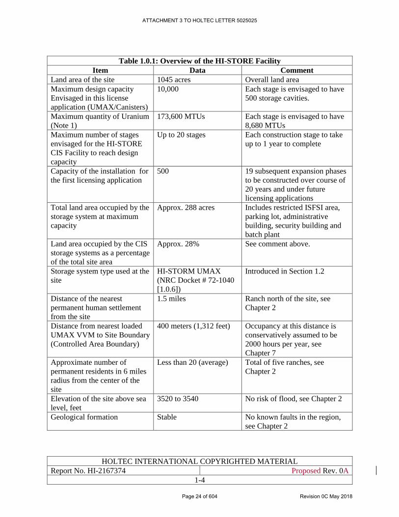
HOLTEC INTERNATIONAL COPYRIGHTED MATERIAL
Report No. HI-2167374 Proposed Rev. 0A
1-4
Table 1.0.1: Overview of the HI-STORE Facility
Item Data Comment
Land area of the site 1045 acres Overall land area
Maximum design capacity
Envisaged in this license
application (UMAX/Canisters)
10,000 Each stage is envisaged to have
500 storage cavities.
Maximum quantity of Uranium
(Note 1)
173,600 MTUs Each stage is envisaged to have
8,680 MTUs
Maximum number of stages
envisaged for the HI-STORE
CIS Facility to reach design
capacity
Up to 20 stages Each construction stage to take
up to 1 year to complete
Capacity of the installation for
the first licensing application
500 19 subsequent expansion phases
to be constructed over course of
20 years and under future
licensing applications
Total land area occupied by the
storage system at maximum
capacity
Approx. 288 acres Includes restricted ISFSI area,
parking lot, administrative
building, security building and
batch plant
Land area occupied by the CIS
storage systems as a percentage
of the total site area
Approx. 28% See comment above.
Storage system type used at the
site
HI-STORM UMAX
(NRC Docket # 72-1040
[1.0.6])
Introduced in Section 1.2
Distance of the nearest
permanent human settlement
from the site
1.5 miles Ranch north of the site, see
Chapter 2
Distance from nearest loaded
UMAX VVM to Site Boundary
(Controlled Area Boundary)
400 meters (1,312 feet) Occupancy at this distance is
conservatively assumed to be
2000 hours per year, see
Chapter 7
Approximate number of
permanent residents in 6 miles
radius from the center of the
site
Less than 20 (average) Total of five ranches, see
Chapter 2
Elevation of the site above sea
level, feet
3520 to 3540 No risk of flood, see Chapter 2
Geological formation Stable No known faults in the region,
see Chapter 2
ATTACHMENT 3 TO HOLTEC LETTER 5025025
Page 24 of 604 Revision 0C May 2018
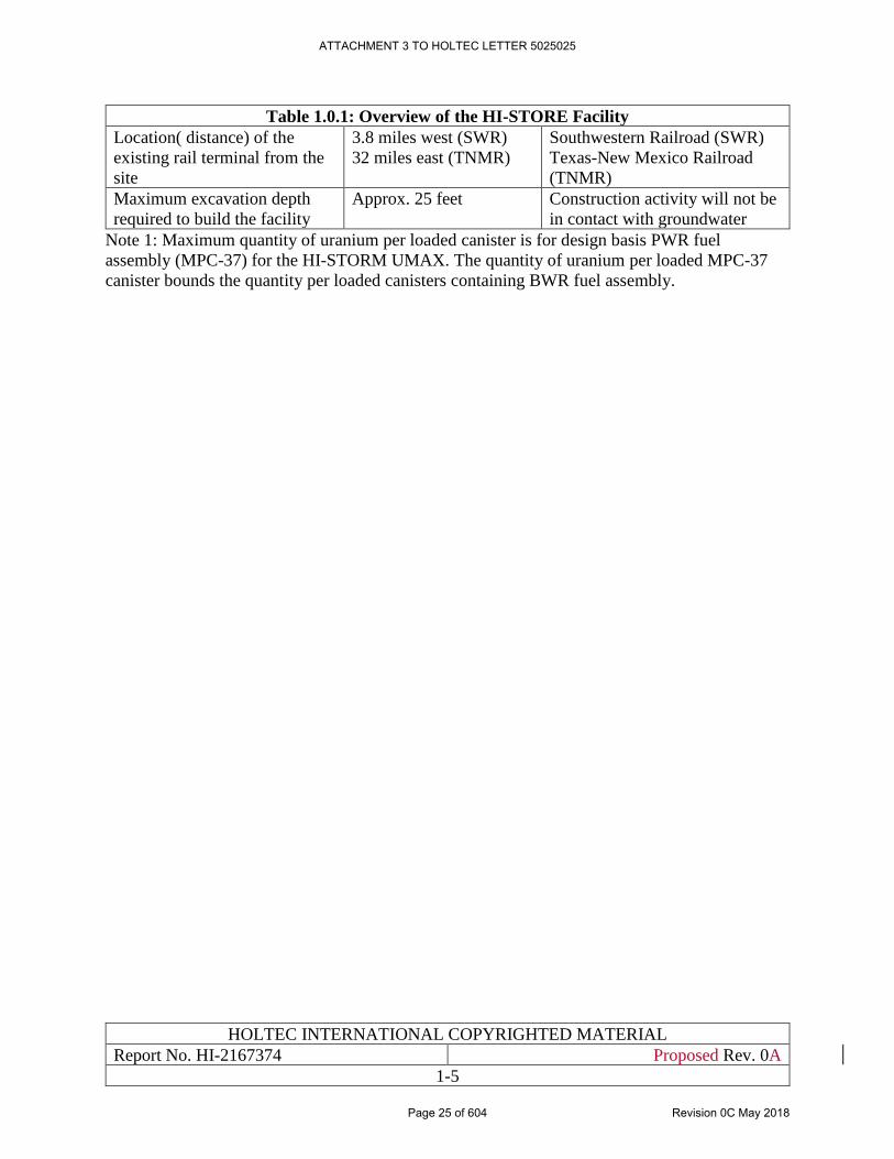
HOLTEC INTERNATIONAL COPYRIGHTED MATERIAL
Report No. HI-2167374 Proposed Rev. 0A
1-5
Table 1.0.1: Overview of the HI-STORE Facility
Location( distance) of the
existing rail terminal from the
site
3.8 miles west (SWR)
32 miles east (TNMR)
Southwestern Railroad (SWR)
Texas-New Mexico Railroad
(TNMR)
Maximum excavation depth
required to build the facility
Approx. 25 feet Construction activity will not be
in contact with groundwater
Note 1: Maximum quantity of uranium per loaded canister is for design basis PWR fuel
assembly (MPC-37) for the HI-STORM UMAX. The quantity of uranium per loaded MPC-37
canister bounds the quantity per loaded canisters containing BWR fuel assembly.
ATTACHMENT 3 TO HOLTEC LETTER 5025025
Page 25 of 604 Revision 0C May 2018
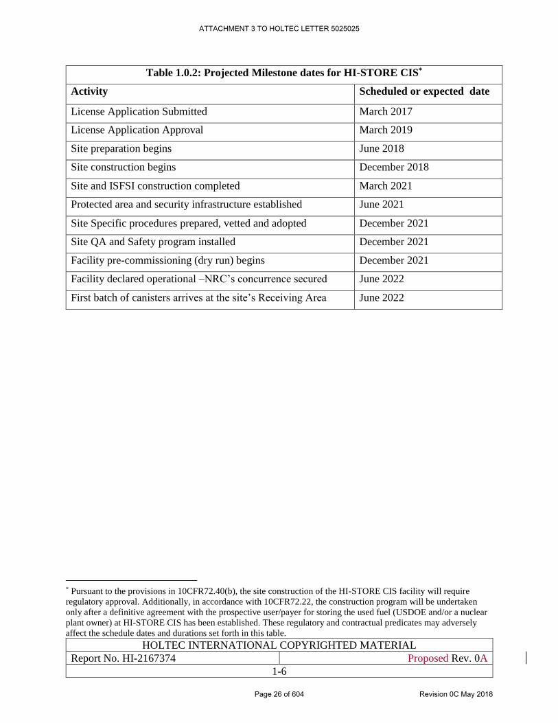
HOLTEC INTERNATIONAL COPYRIGHTED MATERIAL
Report No. HI-2167374 Proposed Rev. 0A
1-6
Table 1.0.2: Projected Milestone dates for HI-STORE CIS*
Activity Scheduled or expected date
License Application Submitted March 2017
License Application Approval March 2019
Site preparation begins June 2018
Site construction begins December 2018
Site and ISFSI construction completed March 2021
Protected area and security infrastructure established June 2021
Site Specific procedures prepared, vetted and adopted December 2021
Site QA and Safety program installed December 2021
Facility pre-commissioning (dry run) begins December 2021
Facility declared operational –NRC’s concurrence secured June 2022
First batch of canisters arrives at the site’s Receiving Area June 2022
* Pursuant to the provisions in 10CFR72.40(b), the site construction of the HI-STORE CIS facility will require
regulatory approval. Additionally, in accordance with 10CFR72.22, the construction program will be undertaken
only after a definitive agreement with the prospective user/payer for storing the used fuel (USDOE and/or a nuclear
plant owner) at HI-STORE CIS has been established. These regulatory and contractual predicates may adversely
affect the schedule dates and durations set forth in this table.
ATTACHMENT 3 TO HOLTEC LETTER 5025025
Page 26 of 604 Revision 0C May 2018
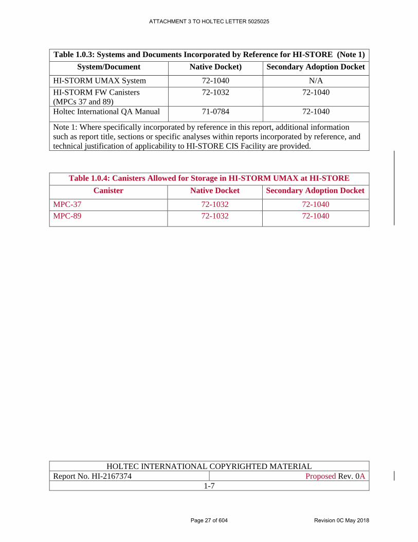
HOLTEC INTERNATIONAL COPYRIGHTED MATERIAL
Report No. HI-2167374 Proposed Rev. 0A
1-7
Table 1.0.3: Systems and Documents Incorporated by Reference for HI-STORE (Note 1)
System/Document Native Docket) Secondary Adoption Docket
HI-STORM UMAX System 72-1040 N/A
HI-STORM FW Canisters
(MPCs 37 and 89)
72-1032 72-1040
Holtec International QA Manual 71-0784 72-1040
Note 1: Where specifically incorporated by reference in this report, additional information
such as report title, sections or specific analyses within reports incorporated by reference, and
technical justification of applicability to HI-STORE CIS Facility are provided.
Table 1.0.4: Canisters Allowed for Storage in HI-STORM UMAX at HI-STORE
Canister Native Docket Secondary Adoption Docket
MPC-37 72-1032 72-1040
MPC-89 72-1032 72-1040
ATTACHMENT 3 TO HOLTEC LETTER 5025025
Page 27 of 604 Revision 0C May 2018
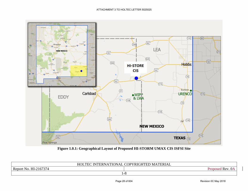
HOLTEC INTERNATIONAL COPYRIGHTED MATERIAL
Report No. HI-2167374 Proposed Rev. 0A
1-8
Figure 1.0.1: Geographical Layout of Proposed HI-STORM UMAX CIS ISFSI Site
ATTACHMENT 3 TO HOLTEC LETTER 5025025
Page 28 of 604 Revision 0C May 2018
HOLTEC INTERNATIONAL COPYRIGHTED MATERIAL
Report No. HI-2167374 Proposed Rev. 0A
1-9
1.1 GENERAL DESCRIPTION OF INSTALLATION
The HI-STORE CIS Facility layout drawing in Section 1.5 provides the general arrangement of
the HI-STORE CIS Facility. The facility (site) layout drawing depicts the site at design basis
capacity (Table 1.0.1). However, this application is limited to the initial licensing capacity (Table
1.0.1). As shown in the layout drawing, the HI-STORE CIS consists of the following SSCs:
a. The HI-STORM UMAX VVMs (Figure 1.2.2)
b. Rail Spur and Cask receiving area
c. Equipment Building to store HI-TRAC, the Vertical Cask Transporter, ancillaries and spare
parts.
d. Administrative Building to house inspection, security and administrative staff as well as
access control facilities.
e. Security Building at the entrance to ISFSI to house security personnel, some health physics
staff as required and some health physics or other monitoring instruments.
The following features of the Facility are important to its safety and security functions and to its
emergency preparedness:
a. Each ISFSI pad is separated from its adjacent pad by a substantial mass of earth (Table
1.1.1) to ensure that the excavation for a pad with an adjacent operating ISFSI would not
introduce a geo-structural or shielding problem.
b. As can be seen from Figure 1.2.1, there are no large obstructions in the storage region that
may block the visual ability to identify an intruder.
c. The storage pads and ISFSI at large are equipped with an efficient drainage system.
d. Parking facility for cars, trucks and other conveyances are located far from the fuel storage
area to preclude the risk of a mass fire from combustion of fuel or transmission fluid.
e. A substantial area adjacent to the loaded ISFSI is cleared of any brush or foliage that may
serve as a fire stimulant.
f. The data in Table 1.1.1 provides additional information on the HI-STORE Facility. The
HI-STORE facility systems descriptions are provided in Section 1.2.
ATTACHMENT 3 TO HOLTEC LETTER 5025025
Page 29 of 604 Revision 0C May 2018
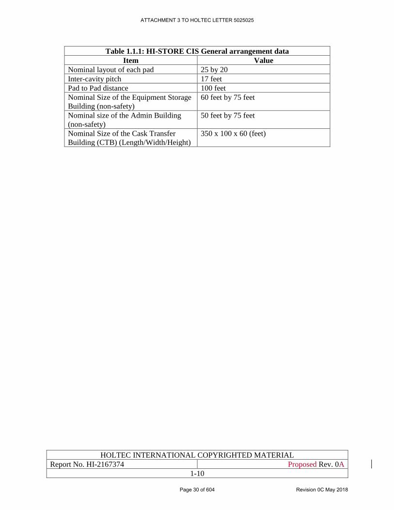
HOLTEC INTERNATIONAL COPYRIGHTED MATERIAL
Report No. HI-2167374 Proposed Rev. 0A
1-10
Table 1.1.1: HI-STORE CIS General arrangement data
Item Value
Nominal layout of each pad 25 by 20
Inter-cavity pitch 17 feet
Pad to Pad distance 100 feet
Nominal Size of the Equipment Storage
Building (non-safety)
60 feet by 75 feet
Nominal size of the Admin Building
(non-safety)
50 feet by 75 feet
Nominal Size of the Cask Transfer
Building (CTB) (Length/Width/Height)
350 x 100 x 60 (feet)
ATTACHMENT 3 TO HOLTEC LETTER 5025025
Page 30 of 604 Revision 0C May 2018
HOLTEC INTERNATIONAL COPYRIGHTED MATERIAL
Report No. HI-2167374 Proposed Rev. 0A
1-11
1.2 GENERAL SYSTEMS DESCRIPTION
1.2.1 HI-STORM UMAX System Overview
The centerpiece of the HI-STORE CIS facility is the HI-STORM UMAX canister storage system
certified in NRC docket # 72-1040. HI-STORM UMAX is the subterranean version of HI-STORM
FW and HI-STORM 100 of which the latter was the reference storage system for the licensed AFR
site scheduled to be sited in the PFS LLC's Skull Valley, Utah licensed in 2006 in docket # 72-22.
The HI-STORM UMAX stores a hermetically sealed canister containing spent nuclear fuel in a
subterranean in-ground Vertical Ventilated Module (VVM). The safety evaluation of HI-STORM
UMAX is maintained in USNRC docket # 72-1040. The annex identifier UMAX is an acronym
of Underground MAXimum safety.
HI-STORM UMAX is a dry, in-ground spent fuel storage system consisting of any number of
Vertical Ventilated Modules (VVMs) each containing one canister. The HI-STORM UMAX has
all the safety attributes that are attributed to in-ground storage, such as enhanced protection from
incident projectiles and threats from extreme environmental phenomena such as hurricanes,
tornado borne missiles, earthquakes, tsunamis, fires, and explosions. Figure 1.2.1 provides a
pictorial illustration of an array of HI-STORM UMAX systems that depicts its security-friendly
diminutive profile.
The HI-STORM UMAX version that will be employed in the HI-STORE CIS is essentially the
design (without the ultra-high earthquake-resistant options, referred to as MSE options) licensed
in the HI-STORM UMAX docket (72-1040). The only other respect in which the HI-STORE VVM
design differs from the generic FSAR design is the provision that the storage cavity depth is made
fixed (not variable, as permitted in the general certification) at two discrete dimensions. The height
of the lateral seismic restraint at the top of the canister is adjusted to accord with the height of the
canister that will be stored in the cavity, and a second set of seismic restraints are situated between
the Divider Shell and Cavity Enclosure Container (CEC) at the same height and location as the
lateral seismic restraint. As a result, the structural performance of the system remains unaffected
and other safety metrics such as shielding and thermal (heat rejection) are either unaffected or
improved (depending on the height of the canister being stored).
To differentiate this minor tweak to the HI-STORM UMAX configuration deployed in the past,
the HI-STORM UMAX drawings in Section 1.5 of this chapter refer to the HI-STORE VVM as
Version C. Version C's certification basis remains in docket # 72-1040; it is not a new embodiment
from a certification standpoint. The drawing package for Version C is included in this SAR
principally to avoid having to refer to the drawing sets in the HI-STORM UMAX FSAR, which
include several geometric options not used in the Version C design.
The essential characteristics of HI-STORM UMAX that make it uniquely suitable to serve as the
heart of the proposed consolidated interim storage facility are:
a. The canister is stored below-grade which makes it essentially invulnerable to the various
extreme environmental phenomena that arise in nature. The intensity of the earthquake for
ATTACHMENT 3 TO HOLTEC LETTER 5025025
Page 31 of 604 Revision 0C May 2018
HOLTEC INTERNATIONAL COPYRIGHTED MATERIAL
Report No. HI-2167374 Proposed Rev. 0A
1-12
which the HI-STORM UMAX system is qualified (documented in this SAR) bounds the
Design Basis Earthquake for the site.
b. The HI-STORM UMAX storage system provides an essentially inviolable protection to the
stored canisters against incident missiles such as a crashing aircraft. The source of the
structural protection of the canister in HI-STORM UMAX lies in the fact that the only path
for an incident missile to access the canister is by piercing the thick lid which is made of a
steel weldment buttressed by concrete. The lateral surface of the canister is protected by a
self-hardening engineered subgrade (SES) around each canister and by the surrounding
expanse of the earth beyond. While the top lid is presently designed for 10CFR72 Design
Basis Missiles, it can be effortlessly swapped for an even more impregnable lid structure
if the level severity of threat to the facility were to increase in the future.
c. The storage cavity of HI-STORM UMAX is sufficiently large to accommodate every
canister type licensed under different 10CFR72 dockets and in use in the United States at
this time. Therefore, it is possible to qualify the entire universe of used fuel canisters
presently deployed at the ISFSIs around the country for storage in the HI-STORM UMAX
system. HI-STORM UMAX is intended to provide a safe and regulation-compliant storage
for even NUHOMS canisters which are normally stored horizontally. (The safety analysis
in support of LAR# 3 to the HI-STORM UMAX CoC indicates that all metrics for safe
storage including decay heat rejection are maintained or improved when a canister is
rotated to the vertical storage orientation in HI-STORM UMAX from its native horizontal
storage in NUHOMS. LAR # 3 to the HI-STORM UMAX CoC is not a part of this
application, but may be incorporated through a licensing action at a later date)
d. Because the on-site canister transfer operation (described in Section 10.3 herein) occurs
vertically (specifically, doesn’t involve horizontal pushing or pulling of the heavy loaded
canister against surface friction), there is no risk of gouging or scratching of the ASME
code boundary of the canister. This is an important benefit at a CIS site where (presumably)
thousands of canisters will be handled.
e. As can be ascertained from the design information in this SAR, the HI-STORM UMAX
CIS features no above-ground important-to-safety building structure. All canister transfer
facilities are below-ground.
f. As described in the canister Aging Management Program [1.2.1], a canister installed in a
HI-STORM UMAX cavity can be remotely examined to assay the state of integrity of its
confinement boundary shell making its long term monitoring a low dose activity.
g. Because of its below-ground fuel storage configuration, the HI-STORM UMAX CIS meets
the site boundary accident dose limit of 10CFR72.106 with large margins, as quantified in
Section 7.4 of this SAR. The minuscule accreted dose, zero effluent release, and extreme
hazard-resistance features of the HI-STORM UMAX CIS facility will make its footprint
on the environment vanishingly small, as described in the Environmental Report [1.0.4].
h. The canister's confinement boundary consists of thick circular stainless steel plate-type
parts at the two extremities joined by a relatively thin shell. As a result, it is the canister's
ATTACHMENT 3 TO HOLTEC LETTER 5025025
Page 32 of 604 Revision 0C May 2018
HOLTEC INTERNATIONAL COPYRIGHTED MATERIAL
Report No. HI-2167374 Proposed Rev. 0A
1-13
shell that has been the focus of stress corrosion cracking threat over prolonged periods of
storage. Unlike horizontally disposed canister, the canister shell in HI-STORM UMAX is
not in physical contact with any other structure precluding the risk of crevice corrosion,
galvanic corrosion, etc.
Finally, it is instructive to note that the canister in HI-STORM UMAX is laterally confined at its
top and bottom extremities inside the HI-STORM UMAX VVM cavity so that it would not
significantly move or rattle under a seismic event. Thus the thermal-hydraulic flow configuration
around the canister is fixed for the duration of storage. This lateral fixity feature in the HI-STORM
UMAX storage system along with its subterranean disposition are key reasons that underlie its
ability to withstand severe earthquakes.
All HI-STORM UMAX System components are and their sub-components are categorized as ITS,
as applicable, in accordance with NUREG/CR-6407 [1.2.2].
To summarize, the HI-STORM UMAX System has been engineered to:
• maximize shielding and physical protection for the canister;
• minimize the extent of handling of the SNF;
• minimize dose to operators during loading and handling;
• require minimal ongoing surveillance and maintenance by plant staff;
• facilitate SNF transfer of the loaded canister to a compatible transport overpack for
transportation;
1.2.2 Constituents of the HI-STORM UMAX Vertical Ventilated Module and ISFSI
Structures
The HI-STORM UMAX VVM, shown in the licensing drawing in Section 1.5 provides for storage
of the canister in a vertical configuration inside a subterranean cylindrical cavity entirely below
the top-of-grade (TOG) of the ISFSI. The key constituents of a HI-STORM UMAX VVM and
ISFSI structures are:
(i) VVM Components
a. The Cavity Enclosure Container (CEC)
b. The Divider Shell
c. The Closure Lid
(ii) ISFSI Structures
d. The ISFSI Pad
e. The Support Foundation Pad
f. The Subgrade and Under-grade
A brief description of each constituent part is provided in the following:
ATTACHMENT 3 TO HOLTEC LETTER 5025025
Page 33 of 604 Revision 0C May 2018
HOLTEC INTERNATIONAL COPYRIGHTED MATERIAL
Report No. HI-2167374 Proposed Rev. 0A
1-14
a. Cavity Enclosure Container:
The Cavity Enclosure Container (CEC) consists of a thick walled shell integrally welded to a
bottom plate. The top of the container shell is stiffened by a ring shaped flange which is also
integrally welded. The constituent parts of the CEC are made of low carbon steel plate. In its
installed configuration, the CEC is interfaced with the surrounding subgrade for most of its height
except for the top region where it is encased in the ISFSI pad.
With the Closure Lid removed, the CEC is a closed bottom, open top, thick walled cylindrical
vessel that has no penetrations or openings. Thus, groundwater has no path for intrusion into the
interior space of the CEC. Likewise, any water that may be introduced into the CEC through the
air passages in the top lid will not drain into the groundwater.
The CEC top contains an air plenum box which works in conjunction with the Closure Lid to
channel incoming air into the down-comer flowing region of the CEC. The air plenum box also
contains rigid embedded locations for securing the HI-TRAC CS against movement during
Canister Transfer operations.
b. Divider Shell:
The Divider Shell is important to the thermal performance of the VVM system. The Divider Shell,
as its name implies, is a removable vertical cylindrical shell concentrically situated in the CEC that
divides the CEC into an inlet flow down-comer and an outlet flow passage. The Divider Shell
divides the radial space between the canister and the CEC cavity into two annuli. The bottom end
of the Divider Shell has cutouts to enable movement of air from the down-comer to the up-flow
region around the canister. The cutouts in the Divider Shell are sufficiently tall to ensure that if
the cavity were to be filled with water, the bottom region of the canister would be submerged to a
depth of several inches. This design feature ensures adequate thermal performance of the system
if flood water were to block air flow. The Divider Shell is not attached to the CEC which allows
its convenient removal for decommissioning or for any in-service maintenance or periodic
inspection.
The cylindrical surface of the Divider Shell is equipped with insulation to prevent significant
preheating of the inlet air. The insulation material is selected to be water and radiation resistant as
well as non-degradable under accidental wetting.
c. The Closure Lid:
The Closure Lid is a steel structure filled with plain concrete that can withstand the impact of the
Design Basis Missiles defined for the site. Both the inlet and outlet vents are located at the grade
level. The Closure Lid internals form segregated air channels for air inlet and outlet. A set of inlet
passage located on top of the CEC provide maximum separation from the large outlet passage
which is located in the center of the lid and channel the inlet air into the CEC’s air plenum box.
As depicted in the licensing drawings in Section 1.5, the geometry of the inlet and outlet ducts
make the HI-STORM UMAX VVM essentially insensitive to the direction and speed of the wind.
The Closure Lid fulfills the following principal performance objectives:
ATTACHMENT 3 TO HOLTEC LETTER 5025025
Page 34 of 604 Revision 0C May 2018
HOLTEC INTERNATIONAL COPYRIGHTED MATERIAL
Report No. HI-2167374 Proposed Rev. 0A
1-15
1 The Closure Lid is physically constrained against horizontal movement during a Design
Basis Earthquake event or a tornado missile strike.
2 To minimize the radiation emitted from the storage cavity, a portion of the Closure Lid
extends into the cylindrical space above the canister. This cylindrical below-surface
extension of the Closure Lid is also made of steel filled with shielding concrete to maximize
the blockage of skyward radiation issuing from the canister.
3 As can be seen from the drawings in Section 1.5, the Closure Lid is substantially larger in
diameter than the CEC and the canister is positioned to be at a significant vertical depth
below the top of the Container Flange. These geometric provisions ensure that the Closure
Lid will not fall into the canister storage cavity space and strike the canister were to
accidentally drop during its handling. Because the Closure Lid is the only removable heavy
load, the carefully engineered design features to facilitate recovery from its accidental drop
provide added assurance that a handling accident at the ISFSI will not lead to any
radiological release. This additional measure against accidental Closure Lid drop does not
replace the drop prevention features mandated in this Safety Report on heavy load lifting
devices (such as the cask transporter) that have been a standard and established requirement
in the HI-STORM dockets.
d. The ISFSI Pad:
The ISFSI Pad serves to augment shielding, to provide a sufficiently stiff riding surface for the
cask transporter, to act as a barrier against gravity-induced seepage of rain or floodwater around
the VVM body as well as to shield against a missile. The ISFSI pad is a monolithic reinforced
concrete structure that provides the load bearing surface for the cask transporter. The appropriate
requirements on the structural strength of the ISFSI pad are specified in Section 4.3.
e. The Support Foundation Pad:
The Support Foundation Pad (SFP) is the underground pad which supports the HI-STORM UMAX
ISFSI. The SFP on which the VVM rests must be designed to minimize long-term settlement. The
SFP and the under-grade must have sufficient strength to support the weight of all the loaded
VVMs during long-term storage and earthquake conditions. As the weight of the loaded VVM is
comparable to the weight of the subgrade which it replaces, the additional pressure acting on the
SFP is quite small. The appropriate requirements on the structural strength of the SFP are specified
in Section 4.3.
f. The Subgrade and Under-grade:
The lateral space between each CEC, the SFP and the ISFSI pad is referred to as the subgrade and
is filled with a Controlled Low-Strength Material (CLSM). Alternatively, “lean concrete” may also
be used.
CLSM is a self-compacted, cementitious material used primarily as a backfill in place of
compacted fill. ACI 229R-99 notes several terms, such as flowable fill, unshrinkable fill,
controlled density fill, flowable mortar, flowable fly ash, fly ash slurry, plastic soil-cement and
soil-cement slurry to describe CLSMs. ACI 116R-00 defines lean concrete as a material with low
ATTACHMENT 3 TO HOLTEC LETTER 5025025
Page 35 of 604 Revision 0C May 2018
HOLTEC INTERNATIONAL COPYRIGHTED MATERIAL
Report No. HI-2167374 Proposed Rev. 0A
1-16
cementitious content. CLSM and lean concrete are also referred to as “Self-hardening Engineered
Subgrade” (SES).
The subgrade material must meet the shear velocity and density requirements in Section 4.3. The
space below the SFP is referred to as the under-grade.
Evaluations in Section 5.4 show that the Self-hardening Engineered Subgrade (SES) provides a
stable lateral support system to the ISFSI under the Design Basis Earthquake. The interface
between the SES and the native subgrade defines the radiation protection boundary of the ISFSI.
1.2.3 Design Characteristics of the HI-STORM UMAX VVM
All HI-STORM UMAX locations are alike except for their cavity depth. The design of HI-STORM
UMAX cavities has been standardized into certain discrete depths as tabulated in the Licensing
Drawing Package (Section 1.5). Different depth HI-STORM UMAX cavities enable canisters of
different heights to be housed in the cavity of appropriate depth. The maximum HI-STORM
UMAX cavity depth corresponds to that certified in docket # 72-1040.
The liberal pitch between the CEC cavities, as shown in the Licensing Drawing package, allows
the Cask Transporter to traverse over any storage cavity and independently access any storage
location. Thus, any canister located in any storage cavity can be independently accessed and
retrieved using a qualified Vertical Cask Transporter (VCT) and a suitable transfer cask.
The essential design and operational features of the HI-STORM UMAX System are:
a. Because of its underground staging in HI-STORM UMAX, tip-over of the canister in
storage is not possible.
b. In HI-STORM UMAX Version C, there are two fixed cavity depths referred to as Type SL
and Type XL, respectively. Type SL cavity is sized to permit storage of all BWR fuel
bearing canisters and PWR canisters that are shorter than the reference BWR canister. Type
XL is a deeper cavity sized to accommodate the canisters that accommodate SNF from
South Texas and AP-1000 plants (which are exceptionally long). The vast majority of the
storage cavities will be of the “SL” type. For all canister heights, the VVM constraint at
the top of the canister are positioned to engage with the structurally robust canister lid
where the Divider Shell is also hardened against lateral loads.
c. To exploit the biological shielding provided by the surrounding soil subgrade, the canister
is entirely situated well below the top-of-grade level. The open plenum above the canister
also acts to boost the ventilation action of the coolant air.
d. Removal of water from the bottom of the storage cavity can be carried out by the simple
expedient use of a flexible hose inserted through the air inlet or outlet passageways.
e. All practical efforts are made to coat exposed surfaces of the VVM with proven low VOC
and/or ANSI/NSF Standard 61 [1.2.3] compliant surface preservatives to preclude
toxicological effects on the environment to the maximum reasonable extent.
1.2.3.1 Shielding Materials
ATTACHMENT 3 TO HOLTEC LETTER 5025025
Page 36 of 604 Revision 0C May 2018
HOLTEC INTERNATIONAL COPYRIGHTED MATERIAL
Report No. HI-2167374 Proposed Rev. 0A
1-17
Steel, concrete, and the subgrade are the principal shielding materials in the HI-STORM UMAX.
The steel and concrete shielding materials in the Closure Lid provide additional gamma and
neutron attenuation to reduce dose rates.
The fuel basket structure provides the initial attenuation of gamma and neutron radiation emitted
by the radioactive contents. The canister shell, baseplate, and thick lid provide additional gamma
attenuation to reduce direct radiation.
1.2.3.2 Lifting Devices
Lifting and handling devices used to load or unload a canister into the HI-STORM UMAX VVM
shall be designed per Paragraph 1.2.1.5 of the HI-STORM FW FSAR (docket # 72-1032).
The lifting and handling of all heavy loads that are within 10CFR72 jurisdiction, such as the HI-
TRAC (Transfer Cask) and the HI-STORM UMAX Closure Lid, shall be carried out using single
failure proof (see definition in the Glossary) equipment with below-the-hook lifting devices that
comply with the stress limits of ANSI N14.6 [1.2.4] and/or applicable portions of NUREG-0612
[1.2.7].
1.2.3.3 Threaded Anchor Locations
Threaded anchor locations are provided in the CEC Flange region of each CEC. These will serve
as the anchoring location for the device used for canister transfer (Section 10.3). Threaded anchor
locations serve no function during long term storage.
1.2.3.4 Design Life
The design life of the HI-STORM UMAX System is set forth in Table 17.0.1. This is accomplished
by using materials of construction with a long proven history in the nuclear industry, specifying
materials known to withstand their operating environments with little to no degradation (Section
17.2), and protecting material from corrosion by using appropriate mitigation measures.
Maintenance programs, as specified in Section 10.3, are also implemented to ensure that the
service life will exceed the design life. The design considerations that assure the HI-STORM
UMAX System performs as designed include the following:
HI-STORM UMAX VVM and HI-TRAC CS Transfer Cask:
a. Exposure to Environmental Effects
b. Material Degradation
c. Maintenance and Inspection Provisions
Canisters:
a. Corrosion
b. Structural Fatigue Effects
c. Maintenance of Helium Atmosphere
d. Allowable Fuel Cladding Temperatures
ATTACHMENT 3 TO HOLTEC LETTER 5025025
Page 37 of 604 Revision 0C May 2018
HOLTEC INTERNATIONAL COPYRIGHTED MATERIAL
Report No. HI-2167374 Proposed Rev. 0A
1-18
e. Neutron Absorber Boron Depletion
The adequacy of the materials for the designated design life is discussed in Chapter 18 of this
report.
1.2.4 HI-TRAC CS
The proposed transfer cask for the HI-STORE CIS facility to carry out all on-site canister transfer
operations is termed HI-TRAC CS which is a variation of the HI-TRAC VW transfer cask licensed
in docket number 72-1032 for the HI-STORM FW and later adopted for HI-STORM UMAX
system in docket number 72-1040. HI-TRAC CS utilizes steel and higher density concrete,
meeting the requirements in Appendix 1.D of the HI-STORM 100 FSAR [1.3.3] to provide dose
attenuation. HI-TRAC CS is also characterized by a split lid configuration wherein the bottom lid
is in in the form of two halves with both halves engineered to retract or approach symmetrically.
Figure 1.2.3a shows HI-TRAC CS in fully closed and fully open bottom lid configurations.
The design and operational features of HI-TRAC CS are summarized in the following:
a. The body of the cask features two concentric steel shells buttressed by a set of thick radial
ribs that are welded to the two shells. The interstitial annular space between the two shells
is filled with densified plain concrete that meets the requirements of Appendix 1.D of the
HI-STORM 100 FSAR (docket # 72-1014) [1.3.3]. The appellation “CS” indicates that the
transfer cask is “concrete shielded”.
b. The bottom of the HI-TRAC features a pair of articulating, half-moon-shaped shield gates
housed in a heavy steel weldment. The shield gates are made of multiple stacked, thick-
steel plates on a low-friction bearing pad. The shield gates slide in the housing to allow
the passage of the MPC from the HI-TRAC to the HI-STORM UMAX and vice versa. In
the closed position, the shield gates support the weight of the MPC and provide shielding
from the bottom of the loaded MPC. The major advantage of the split door configuration
is that, in the fully retracted state, it does not intrude on the space occupied by the air vent
projection in adjacent HI-STORM UMAX cavities and does not protrude into the canister
vertical travel space. The shield gates feature air passages which allow for once-through
air cooling of the canister (Figure 1.2.3b). The air cooling features of the HI-TRAC CS
supplement the conductive and radiation cooling of the HI-TRAC CS. Ambient air rises
through multiple Z-shaped passages in the shield gates, up through the annulus and out the
open top of the HI-TRAC CS. A segmented alignment ring on the bottom of the HI-TRAC
is used to concentrically align the HI-TRAC with the HI—STORM UMAX CEC during
MPC transfer into the HI-STORM UMAX. The segmented alignment ring allows air to
enter the region beneath the shield gates such that MPC cooling air flow is assured even if
the HI-TRAC is placed flat on the ground. The air passage inlets through the shield gates
passively uses the ground to shield personnel from downward-streaming radiation. The
top region of the cask body features a set of lifting trunnions. The Trunnions are for lifting
and handling of the HI-TRAC via the cask handling crane or VCT. The HI-TRAC bottom
region also features a set of trunnions suitable for cask's tilting operations.
ATTACHMENT 3 TO HOLTEC LETTER 5025025
Page 38 of 604 Revision 0C May 2018
HOLTEC INTERNATIONAL COPYRIGHTED MATERIAL
Report No. HI-2167374 Proposed Rev. 0A
1-19
c. The bottom region of the cask is outfitted with a heavy wall steel structure that houses the
articulating shield gates. The shield gates ride on a low friction surface to enable them to
be pulled apart (or pushed together) with a modest force to open the cask's cavity for
canister transfer when needed. Shield gate opening and closure occurs via a set of hydraulic
cylinders located on the outer edges of the shield gate housing.
d. The shielding concrete in the transfer cask is installed through suitably sized openings in
the cask’s top closure plate which also provide the exit path for any gases that may be
generated during a hypothetical fire event. The HI-TRAC concrete space is supplemented
with an internal cylindrical steel ring that supplements the gamma shielding in the shield
gate region.
e. During the canister transfer operation, the transfer cask is secured to the top pad of the
recipient cavity (HI-STORM UMAX ISFSI pad or the CTF pad) by a set of anchor bolts
which eliminates kinematic stability concerns during the Design Basis Earthquake (DBE)
event or any other credible environmental mechanical loading applicable to the site.
f. The top of the transfer cask features a thick annular steel ring which serves to prevent an
inadvertent lifting of the canister beyond the biological shielding space provided by the
transfer cask and also provides shielding axially.
g. The transfer cask is engineered to directly mate with the HI-STORM UMAX cavity as well
as the Canister Transfer Facility (CTF) cavity eliminating the need for the traditional
Mating Device ancillary. Elimination of the Mating Device has the salutary advantage of
reducing the aggregate crew dose (i.e., promoting ALARA).
The Licensing drawing package in Section 1.5 of this chapter provides the necessary design details
of HI-TRAC CS that support the required safety analyses documented in this SAR.
1.2.5 Operational Characteristics of the HI-STORM UMAX
The major operational steps to load a HI-STORM UMAX cavity consists of the following: The
cask transporter carrying the transfer cask with the loaded canister aligns over the top of the HI-
STORM UMAX and the HI-TRAC is placed on the HI-STORM UMAX VVM. The canister
inside the transfer cask is lifted slightly by the VCT to allow the HI-TRAC’s shield gates be
opened. The canister is slowly lowered into the VVM cavity below. The transfer equipment is
removed and the Closure Lid is installed. The principal operational characteristics of short term
operations at an ISFSI are:
a. Prior to loading the VVM, the Closure Lid or other temporary lid is removed and the
Divider Shell is installed.
b. The HI-TRAC CS cask is mounted on the VVM cavity and secured with large fasteners
that are sized to protect the cask from tip- over under the site’s DBE.
c. The canister is lowered into the storage cavity.
d. After the HI-TRAC Transfer Cask is removed then the Closure Lid is installed.
The loading operation is characterized by the following essential features:
ATTACHMENT 3 TO HOLTEC LETTER 5025025
Page 39 of 604 Revision 0C May 2018
HOLTEC INTERNATIONAL COPYRIGHTED MATERIAL
Report No. HI-2167374 Proposed Rev. 0A
1-20
a. The vertical insertion (or withdrawal) of the canister eliminates the risk of gouging or
binding of the canister with the CEC parts.
b. All load handling operations are carried out using the Vertical Cask Transporter (VCT)
that meets the criteria for lifting devices in Subsection 1.3.3 to preclude uncontrolled
lowering of the load.
Details of the generic operational steps involving either installation or removal of the loaded
canister at the HI-STORE CIS facility are provided in Section 10.3 along with reference to the
safety measures that are known from experience to avert human performance errors. The visual
depiction of the required operational steps in Figures 3.1.1 (a-v) provides a brief illustration of the
loading steps for the HI-STORM UMAX CIS.
1.2.5.1 Design Features
The design features of the HI-STORM UMAX System are intended to meet the following principal
performance characteristics under all credible modes of operation:
a. Prevent unacceptable release of contained radioactive material at all times.
b. Minimize occupational and site boundary dose.
c. Permit retrievability of contents (the canister must be recoverable after accident conditions
in accordance with ISGs 2 and 3 [1.2.5, 1.2.6]).
Chapter 11 identifies the many design features built into the HI-STORM UMAX System to
minimize dose and maximize personnel safety. Among the design features intrinsic to the system
that facilitate meeting the above objectives are:
a. The loaded canister is always maintained in a vertical orientation during its handling at the
ISFSI and is handled using ANSI N14.6 [1.2.4] compliant ancillaries.
b. Almost all personnel activities during canister transfer occur at ground level which helps
promote safety and ALARA.
1.2.5.2 Identification of Subjects for Safety and Reliability Analysis
(a) Criticality Prevention
Every canister brought over to the HI-STORE facility must be approved under a USNRC docket
to store used nuclear fuel or HLW. Therefore, the criticality compliance of the canister at HI-
STORE is assured, as discussed in Chapter 8 of this report.
(b) Chemical Safety
There are no chemical safety hazards associated with operations of the HI-STORM UMAX
System. No chemicals are stored inside the Protected Area.
(c) Operation Shutdown Modes
The HI-STORM UMAX System is totally passive and consequently, operation shutdown modes
are unnecessary.
ATTACHMENT 3 TO HOLTEC LETTER 5025025
Page 40 of 604 Revision 0C May 2018
HOLTEC INTERNATIONAL COPYRIGHTED MATERIAL
Report No. HI-2167374 Proposed Rev. 0A
1-21
(d) Instrumentation
As stated earlier, the HI-STORM UMAX canister, which is seal welded, non-destructively
examined, and pressure tested, confines the radioactive contents. The HI-STORM UMAX is a
completely passive system with appropriate margins of safety; therefore, it is not necessary to
deploy any instrumentation to monitor the cask in the storage mode.
(e) Maintenance Program
Because of its passive nature, the HI-STORM UMAX System requires minimal maintenance over
its lifetime. Section 10.3 describes the maintenance program set forth for the HI-STORM UMAX
System.
1.2.6 Cask Contents
This sub-section contains information on the cask contents pursuant to 10CFR 72.236(a),(m).
Only those canisters certified to be stored in the HI-STORM UMAX system in Docket # 72-1040
are permitted to be stored at HI-STORE CIS Facility.
Section 4.1 provides additional details.
1.2.7 Ancillary Equipment Used at HI-STORE CIS
Ancillary equipment for the HI-STORE CIS are those that are needed to conduct cask and canister
handling and transfer operations in full compliance with the safety and ALARA commitments.
The major ancillary equipment includes:
a. Vertical Cask Transporter
b. Gantry Crane
c. Cask Tilt Frame
d. Special Lifting Devices
The above list does not include minor ancillaries that are available for procurement to the
applicable ANSI standards such as common rigging, ladders, platforms, equipment stands, service
and mobile cranes for handling non-critical loads, etc. The above list does not include commercial
test and measurement equipment such as radiological survey equipment, leak testing equipment
and cask test connectors.
The Design Criteria for the above major ancillaries are provided in Section 4.5, and analyses are
presented in Sections 5.4 and 5.5; a brief description is provided below.
a. Vertical Cask Transporter
The Vertical Cask Transporter (VCT) is the principal load handling device used for MPC transfer
operations at the HI-STORE CIS. Used in conjunction with the special lifting devices, it provides
the critical lifting and handling functions associated with the canister transfer operations. It is a
custom-designed equipment consisting of a set of caterpillars or multiple wheels, a diesel engine
with a robust gear train and transmission housed in a rugged structural frame that also supports a
ATTACHMENT 3 TO HOLTEC LETTER 5025025
Page 41 of 604 Revision 0C May 2018
HOLTEC INTERNATIONAL COPYRIGHTED MATERIAL
Report No. HI-2167374 Proposed Rev. 0A
1-22
set of hydraulically-actuated lifting towers. Figure 1.2.4 illustrates the general configuration of a
VCT. The VCT uses the same controls and redundant drop protection features used to prevent an
unplanned lowering of the critical load under a loss-of-power or hydraulic system failure as used
at other ISFSIs in the United States where the VCT is performing the canister transfer operations.
b. Gantry Crane:
The Cask Handling Crane System consists of a crane, trolley, and hoist(s). The Crane System is
electrically driven and rides on crane rails which are mounted to its supporting structure in the
Cask Receiving Area. The trolley rides on crane rails mounted to the top of the crane girders and
has at least one electric wire rope hoist for load lifting. The hoist hook will be used to lift the load
and shall interface with the required rigging and below the hook lifting devices as required for the
process.
The Crane System shall comply with ASME NOG-1 [3.0.1], and the latest revision of CMAA 70
[4.5.2], and OSHA. Design criteria for the Gantry crane is in Chapter 4 of this SAR.
c. Cask Tilt Frame:
The Cask Tilt Frame is used in conjunction with the Gantry Crane and its special lifting devices to
transfer the HI-STAR 190 Transport Cask between the vertical and horizontal orientations. The
Cask Tilt Frame consist of a set of trunnion support stanchions and a cask support saddle. The
trunnion support stanchions engage the cask’s rotation trunnions and provide a low-friction
rotation point for cask tilting. The saddle supports the upper portion of the cask when the cask
reaches the horizontal orientation. A brief illustration of the upending of a HI-STAR 190 Transport
Cask or using the Crane and Tilt Frame through insertion into the CTF is demonstrated in Chapter
3. Downending of the HI-STAR 190 is performed in the reverse order for shipments away from
the CIS.
d. Special Lifting Devices:
The Special Lifting Devices include those lifting components used to connect the cask or canister
to the Gantry Crane or the VCT’s lift points, as illustrated in Figure 1.2.4. Special Lifting Devices
are defined in ANSI N14.6 [1.2.4].
ATTACHMENT 3 TO HOLTEC LETTER 5025025
Page 42 of 604 Revision 0C May 2018
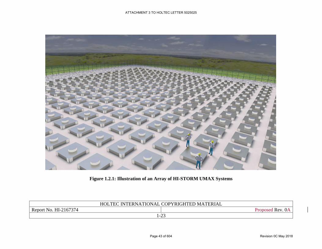
HOLTEC INTERNATIONAL COPYRIGHTED MATERIAL
Report No. HI-2167374 Proposed Rev. 0A
1-23
Figure 1.2.1: Illustration of an Array of HI-STORM UMAX Systems
ATTACHMENT 3 TO HOLTEC LETTER 5025025
Page 43 of 604 Revision 0C May 2018
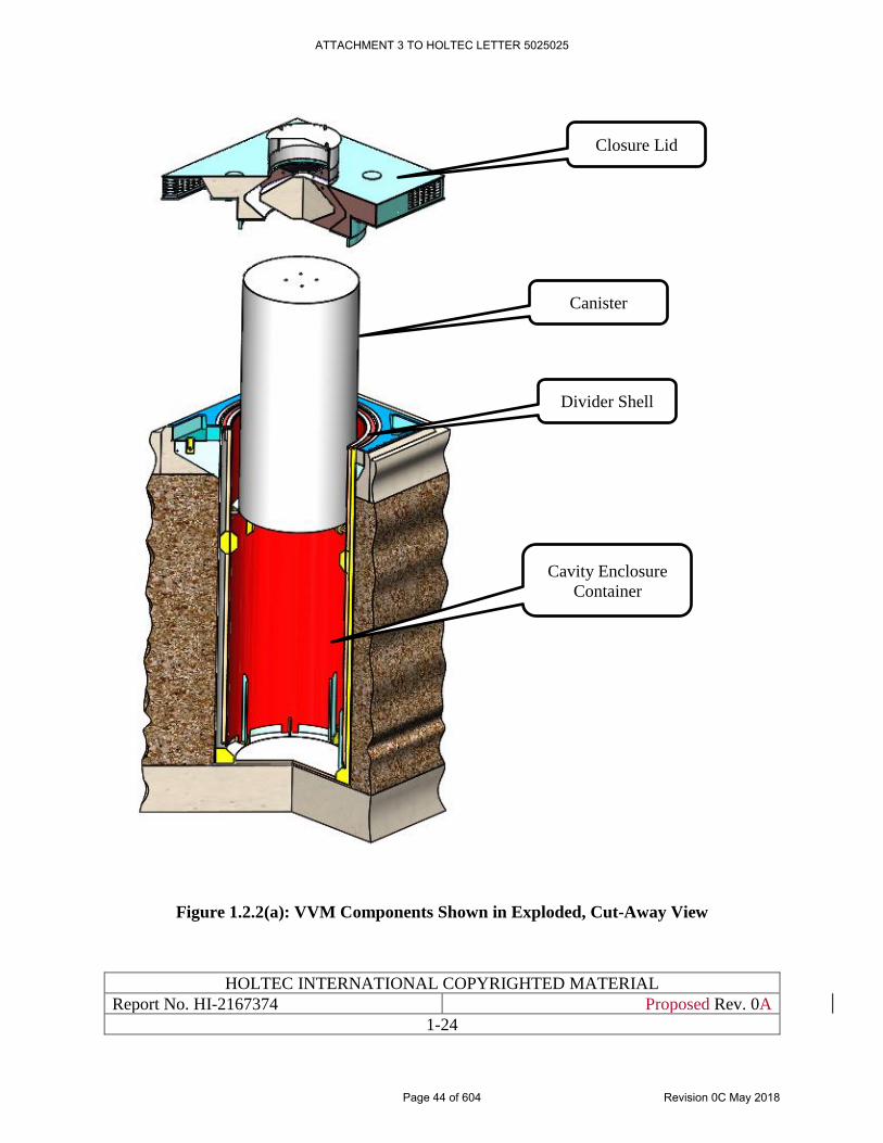
HOLTEC INTERNATIONAL COPYRIGHTED MATERIAL
Report No. HI-2167374 Proposed Rev. 0A
1-24
Figure 1.2.2(a): VVM Components Shown in Exploded, Cut-Away View
Closure Lid
Divider Shell
Cavity Enclosure
Container
Canister
ATTACHMENT 3 TO HOLTEC LETTER 5025025
Page 44 of 604 Revision 0C May 2018
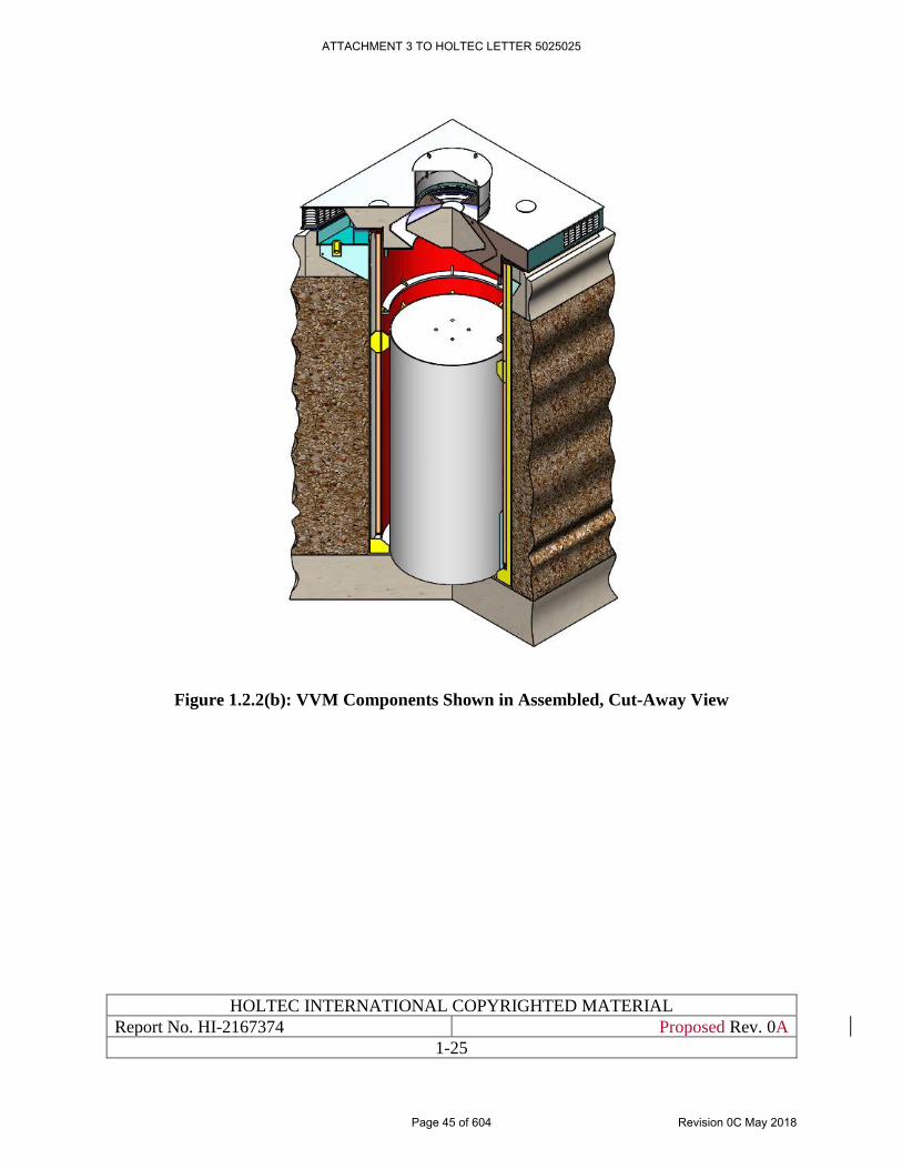
HOLTEC INTERNATIONAL COPYRIGHTED MATERIAL
Report No. HI-2167374 Proposed Rev. 0A
1-25
Figure 1.2.2(b): VVM Components Shown in Assembled, Cut-Away View
ATTACHMENT 3 TO HOLTEC LETTER 5025025
Page 45 of 604 Revision 0C May 2018
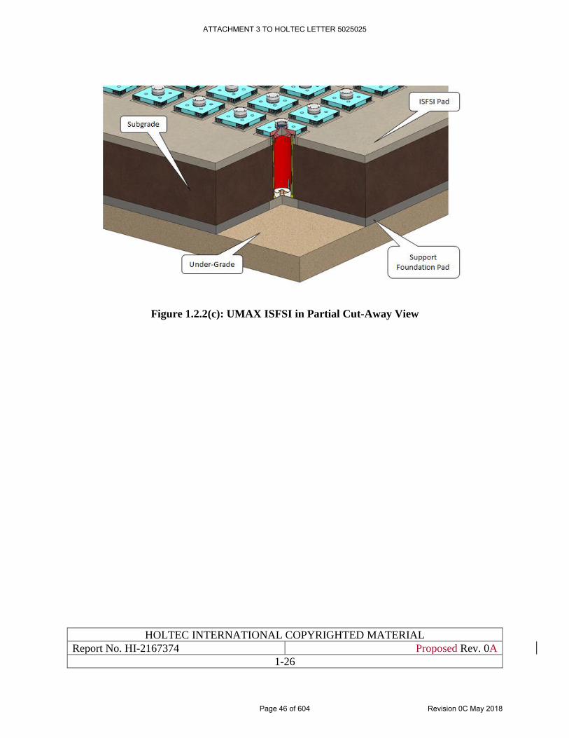
HOLTEC INTERNATIONAL COPYRIGHTED MATERIAL
Report No. HI-2167374 Proposed Rev. 0A
1-26
Figure 1.2.2(c): UMAX ISFSI in Partial Cut-Away View
ATTACHMENT 3 TO HOLTEC LETTER 5025025
Page 46 of 604 Revision 0C May 2018
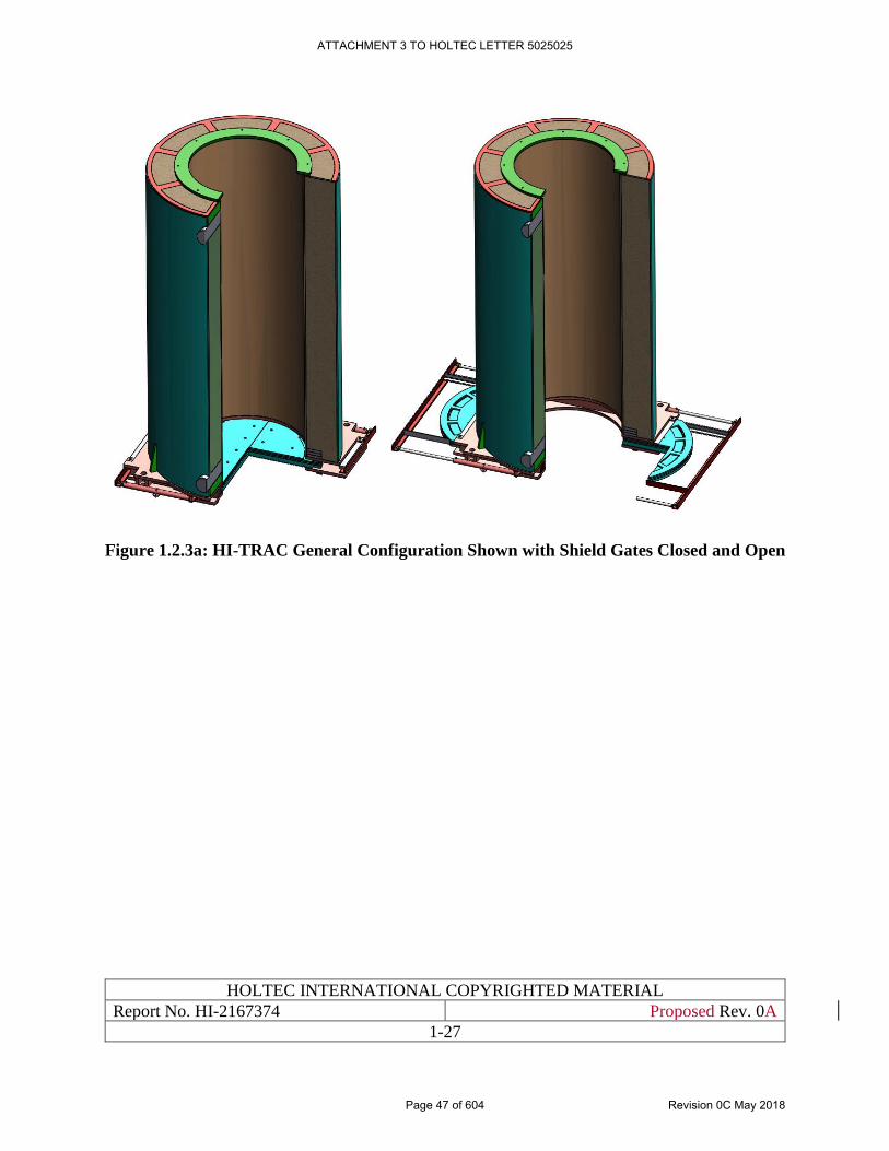
HOLTEC INTERNATIONAL COPYRIGHTED MATERIAL
Report No. HI-2167374 Proposed Rev. 0A
1-27
Figure 1.2.3a: HI-TRAC General Configuration Shown with Shield Gates Closed and Open
ATTACHMENT 3 TO HOLTEC LETTER 5025025
Page 47 of 604 Revision 0C May 2018
HOLTEC INTERNATIONAL COPYRIGHTED MATERIAL
Report No. HI-2167374 Proposed Rev. 0A
1-28
Figure 1.2.3b: [PROPRIETARY INFORMATION WITHHELD PER 10CFR2.390]
ATTACHMENT 3 TO HOLTEC LETTER 5025025
Page 48 of 604 Revision 0C May 2018
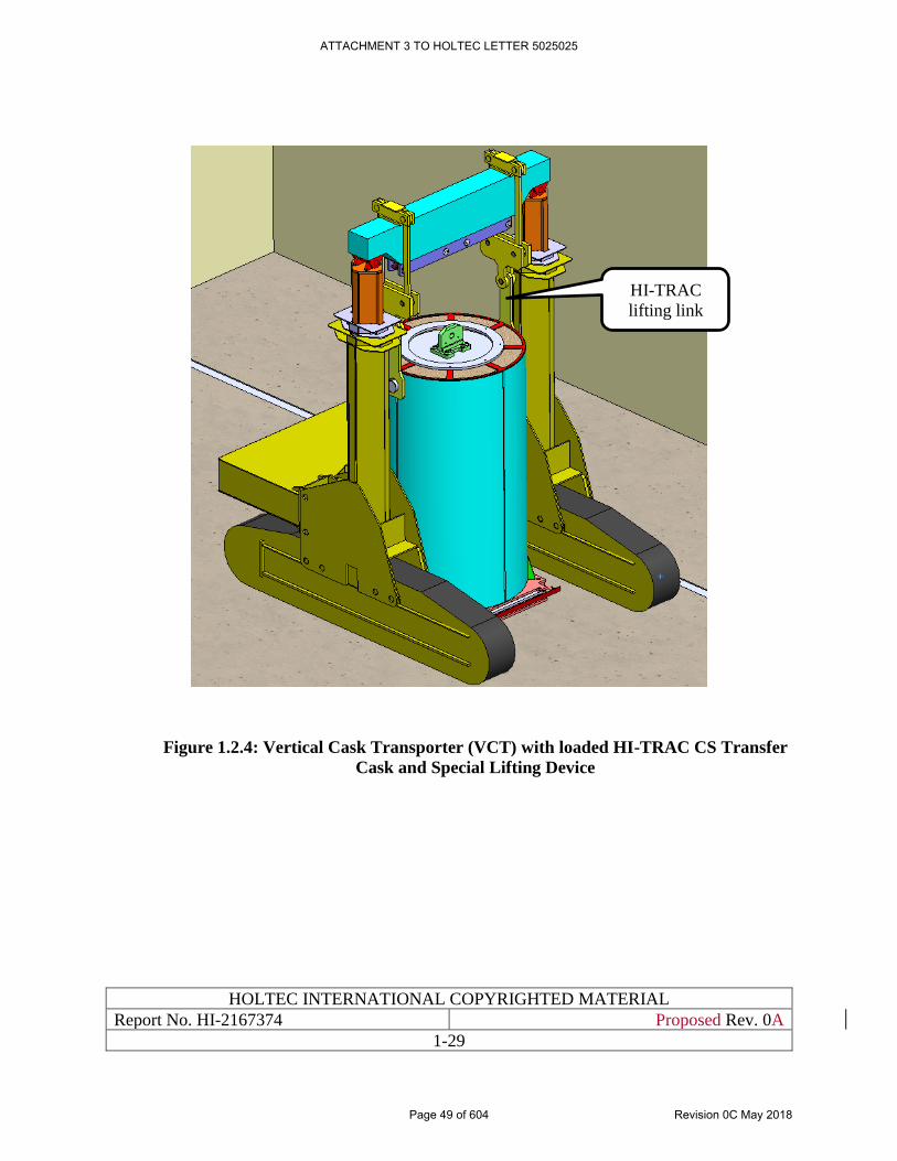
HOLTEC INTERNATIONAL COPYRIGHTED MATERIAL
Report No. HI-2167374 Proposed Rev. 0A
1-29
Figure 1.2.4: Vertical Cask Transporter (VCT) with loaded HI-TRAC CS Transfer
Cask and Special Lifting Device
HI-TRAC
lifting link
ATTACHMENT 3 TO HOLTEC LETTER 5025025
Page 49 of 604 Revision 0C May 2018
HOLTEC INTERNATIONAL COPYRIGHTED MATERIAL
Report No.HI-2167374 Proposed Rev. 0A
1-30
1.3 IDENTIFICATION OF AGENTS AND CONTRACTORS
This section contains the necessary information to fulfill the requirements pertaining to the
qualifications of the applicant pursuant to 10CFR72.22. Holtec International, with its operation
centers in Florida, New Jersey, Pennsylvania, and Ohio in The United States, is the system designer
and applicant for certification of the HI-STORE CIS facility.
Holtec International is an engineering technology company with a principal focus on the power
industry. Holtec International Nuclear Power Division (NPD) specializes in spent fuel storage
technologies. NPD has carried out turnkey wet storage capacity expansions (engineering,
licensing, fabrication, removal of existing racks, performance of underwater modifications,
volume reduction of the old racks and hardware, installation of new racks, and commissioning of
the fuel pool for increased storage capacity) in numerous nuclear plants around the world. Over 90
plants in the U.S., Britain, Brazil, Korea, Mexico, China and Taiwan have utilized the Company’s
wet storage technology to establish their state-of-the-art in-pool storage capacities.
Holtec’s NPD is also a turnkey provider of dry storage and transportation technologies to nuclear
plants around the globe. The company is contracted by 59 nuclear units in the U.S. and 42 overseas
to provide the company’s dry storage and transport systems. Utilities in Belgium, China, Korea,
Spain, South Africa, Sweden, Ukraine, the United Kingdom and Switzerland are also active users
of Holtec International’s dry storage and transport systems.
Four U.S. commercial plants, namely, Dresden Unit 1, Trojan, Indian Point Unit 1, and Humboldt
Bay have thus far been completely defueled using Holtec International’s technology. For many of
its dry storage clients, Holtec International provides all phases of dry storage including: the
required site-specific safety evaluations; ancillary designs; manufacturing of all capital equipment;
preparation of site construction procedures; personnel training; dry runs; and fuel loading. The
USNRC dockets in 10CFR71 and 10CFR72 currently maintained by the Company (as of February
2017) are listed in Table 1.3.1.
Holtec International's corporate engineering consists of professional engineers and experts with
extensive experience in every discipline germane to the fuel storage technologies, namely
structural mechanics, heat transfer, computational fluid dynamics, and nuclear physics. Virtually
all engineering analyses for Holtec's fuel storage projects (including HI-STORM UMAX) are
carried out by the company’s full-time staff. The Company is actively engaged in a continuous
improvement program of the state-of-the-art in dry storage and transport of spent nuclear fuel. The
active patents and patent applications in the areas of dry storage and transport of SNF held by the
Company (ca. June 2016) are listed in Table 1.3.2. Table 1.3.3 lists Holtec patents on dry storage
technologies that have been published by the US patent office but not yet granted. Many of these
listed patents have been utilized in the design of the HI-STORM UMAX System.
Holtec International's quality assurance (QA) program was originally developed to meet NRC
requirements delineated in 10CFR50 [1.3.1], Appendix B, and was expanded to include provisions
of 10CFR71 [1.3.2], Subpart H, and 10CFR72 [1.0.5], Subpart G, for structures, systems, and
components designated as important to safety. The Holtec quality assurance program, which
satisfies all 18 criteria in 10CFR72, Subpart G, that apply to the design, fabrication, construction,
ATTACHMENT 3 TO HOLTEC LETTER 5025025
Page 50 of 604 Revision 0C May 2018
HOLTEC INTERNATIONAL COPYRIGHTED MATERIAL
Report No.HI-2167374 Proposed Rev. 0A
1-31
testing, operation, modification, and decommissioning of structures, systems, and components
important to safety is incorporated by reference into this SAR. Holtec International’s QA program
has been certified by the USNRC (Certificate No. 71-0784) [12.0.1].
The HI-STORM UMAX System will be fabricated by the manufacturing plants owned by Holtec
International and operated under the Company’s QA program. The Company’s HMD in Pittsburgh
is a long-term ASME N-Stamp holder and fabricator of nuclear components. In particular, HMD
has been manufacturing HI-STORM and HI-STAR system components since the inception of
Holtec International’s dry storage and transportation program in the 1990s. HMD routinely
manufactures ASME code components for use in the U.S. and overseas nuclear plants. Holtec
International’s engineering and manufacturing organizations have been subject to triennial
inspections by the USNRC. If another fabricator is to be used for the fabrication of any part of the
HI-STORM UMAX System, the proposed fabricator will be evaluated and audited in accordance
with Holtec International’s QA program approved by the USNRC.
Holtec International’s Nuclear Power Division (NPD) also carries out site services for dry storage
deployments at nuclear power plants. Numerous nuclear plants, such as Trojan and Waterford 3 ,
Waterford 3, Pilgrim and Comanche Peak have deployed dry storage at their sites using a turnkey
contract with Holtec International.
The Company has considerable prior experience in the design and licensing of AFRs sites, having
successfully led the licensing of PFS, LLC’s Skull Valley in Utah (2005) and the “Central Spent
Fuel Storage Facility” in Ukraine (ongoing).
ATTACHMENT 3 TO HOLTEC LETTER 5025025
Page 51 of 604 Revision 0C May 2018
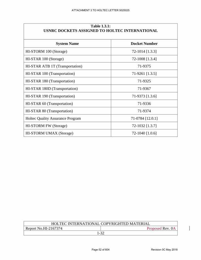
HOLTEC INTERNATIONAL COPYRIGHTED MATERIAL
Report No.HI-2167374 Proposed Rev. 0A
1-32
Table 1.3.1:
USNRC DOCKETS ASSIGNED TO HOLTEC INTERNATIONAL
System Name Docket Number
HI-STORM 100 (Storage) 72-1014 [1.3.3]
HI-STAR 100 (Storage) 72-1008 [1.3.4]
HI-STAR ATB 1T (Transportation) 71-9375
HI-STAR 100 (Transportation) 71-9261 [1.3.5]
HI-STAR 180 (Transportation) 71-9325
HI-STAR 180D (Transportation) 71-9367
HI-STAR 190 (Transportation) 71-9373 [1.3.6]
HI-STAR 60 (Transportation) 71-9336
HI-STAR 80 (Transportation) 71-9374
Holtec Quality Assurance Program 71-0784 [12.0.1]
HI-STORM FW (Storage) 72-1032 [1.3.7]
HI-STORM UMAX (Storage) 72-1040 [1.0.6]
ATTACHMENT 3 TO HOLTEC LETTER 5025025
Page 52 of 604 Revision 0C May 2018
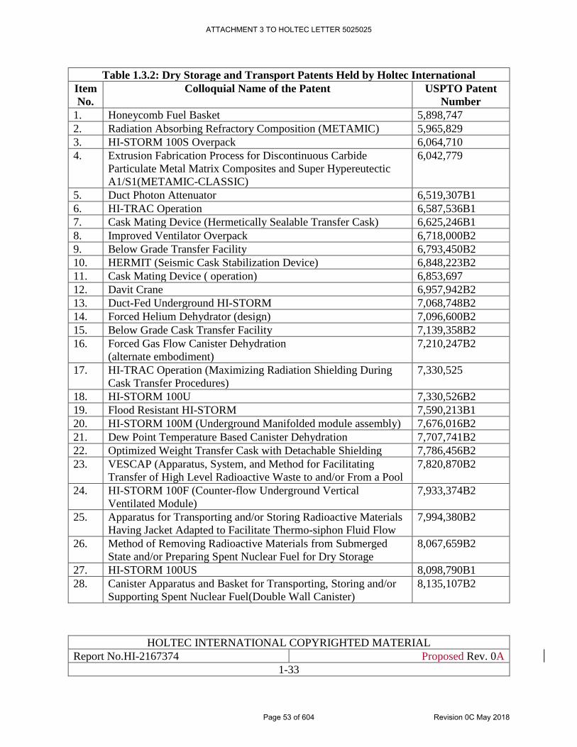
HOLTEC INTERNATIONAL COPYRIGHTED MATERIAL
Report No.HI-2167374 Proposed Rev. 0A
1-33
Table 1.3.2: Dry Storage and Transport Patents Held by Holtec International
Item
No.
Colloquial Name of the Patent USPTO Patent
Number
1. Honeycomb Fuel Basket 5,898,747
2. Radiation Absorbing Refractory Composition (METAMIC) 5,965,829
3. HI-STORM 100S Overpack 6,064,710
4. Extrusion Fabrication Process for Discontinuous Carbide
Particulate Metal Matrix Composites and Super Hypereutectic
A1/S1(METAMIC-CLASSIC)
6,042,779
5. Duct Photon Attenuator 6,519,307B1
6. HI-TRAC Operation 6,587,536B1
7. Cask Mating Device (Hermetically Sealable Transfer Cask) 6,625,246B1
8. Improved Ventilator Overpack 6,718,000B2
9. Below Grade Transfer Facility 6,793,450B2
10. HERMIT (Seismic Cask Stabilization Device) 6,848,223B2
11. Cask Mating Device ( operation) 6,853,697
12. Davit Crane 6,957,942B2
13. Duct-Fed Underground HI-STORM 7,068,748B2
14. Forced Helium Dehydrator (design) 7,096,600B2
15. Below Grade Cask Transfer Facility 7,139,358B2
16. Forced Gas Flow Canister Dehydration
(alternate embodiment)
7,210,247B2
17. HI-TRAC Operation (Maximizing Radiation Shielding During
Cask Transfer Procedures)
7,330,525
18. HI-STORM 100U 7,330,526B2
19. Flood Resistant HI-STORM 7,590,213B1
20. HI-STORM 100M (Underground Manifolded module assembly) 7,676,016B2
21. Dew Point Temperature Based Canister Dehydration 7,707,741B2
22. Optimized Weight Transfer Cask with Detachable Shielding 7,786,456B2
23. VESCAP (Apparatus, System, and Method for Facilitating
Transfer of High Level Radioactive Waste to and/or From a Pool
7,820,870B2
24. HI-STORM 100F (Counter-flow Underground Vertical
Ventilated Module)
7,933,374B2
25. Apparatus for Transporting and/or Storing Radioactive Materials
Having Jacket Adapted to Facilitate Thermo-siphon Fluid Flow
7,994,380B2
26. Method of Removing Radioactive Materials from Submerged
State and/or Preparing Spent Nuclear Fuel for Dry Storage
8,067,659B2
27. HI-STORM 100US 8,098,790B1
28. Canister Apparatus and Basket for Transporting, Storing and/or
Supporting Spent Nuclear Fuel(Double Wall Canister)
8,135,107B2
ATTACHMENT 3 TO HOLTEC LETTER 5025025
Page 53 of 604 Revision 0C May 2018
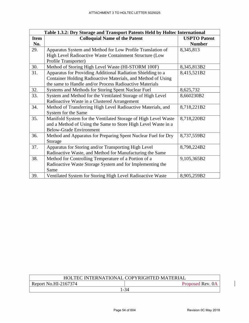
HOLTEC INTERNATIONAL COPYRIGHTED MATERIAL
Report No.HI-2167374 Proposed Rev. 0A
1-34
Table 1.3.2: Dry Storage and Transport Patents Held by Holtec International
Item
No.
Colloquial Name of the Patent USPTO Patent
Number
29. Apparatus System and Method for Low Profile Translation of
High Level Radioactive Waste Containment Structure (Low
Profile Transporter)
8,345,813
30. Method of Storing High Level Waste (HI-STORM 100F) 8,345,813B2
31. Apparatus for Providing Additional Radiation Shielding to a
Container Holding Radioactive Materials, and Method of Using
the same to Handle and/or Process Radioactive Materials
8,415,521B2
32. Systems and Methods for Storing Spent Nuclear Fuel 8,625,732
33. System and Method for the Ventilated Storage of High Level
Radioactive Waste in a Clustered Arrangement
8,660230B2
34. Method of Transferring High Level Radioactive Materials, and
System for the Same
8,718,221B2
35. Manifold System for the Ventilated Storage of High Level Waste
and a Method of Using the Same to Store High Level Waste in a
Below-Grade Environment
8,718,220B2
36. Method and Apparatus for Preparing Spent Nuclear Fuel for Dry
Storage
8,737,559B2
37. Apparatus for Storing and/or Transporting High Level
Radioactive Waste, and Method for Manufacturing the Same
8,798,224B2
38. Method for Controlling Temperature of a Portion of a
Radioactive Waste Storage System and for Implementing the
Same
9,105,365B2
39. Ventilated System for Storing High Level Radioactive Waste 8,905,259B2
ATTACHMENT 3 TO HOLTEC LETTER 5025025
Page 54 of 604 Revision 0C May 2018
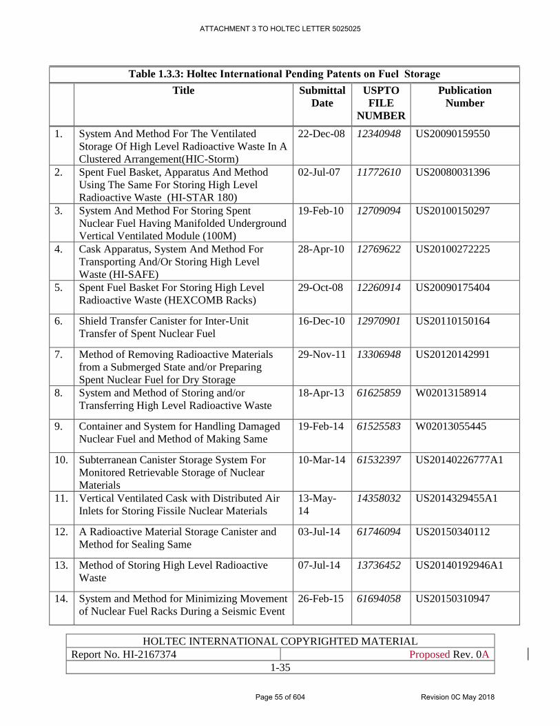
HOLTEC INTERNATIONAL COPYRIGHTED MATERIAL
Report No. HI-2167374 Proposed Rev. 0A
1-35
Table 1.3.3: Holtec International Pending Patents on Fuel Storage
Title Submittal
Date
USPTO
FILE
NUMBER
Publication
Number
1. System And Method For The Ventilated
Storage Of High Level Radioactive Waste In A
Clustered Arrangement(HIC-Storm)
22-Dec-08 12340948 US20090159550
2. Spent Fuel Basket, Apparatus And Method
Using The Same For Storing High Level
Radioactive Waste (HI-STAR 180)
02-Jul-07 11772610 US20080031396
3. System And Method For Storing Spent
Nuclear Fuel Having Manifolded Underground
Vertical Ventilated Module (100M)
19-Feb-10 12709094 US20100150297
4. Cask Apparatus, System And Method For
Transporting And/Or Storing High Level
Waste (HI-SAFE)
28-Apr-10 12769622 US20100272225
5. Spent Fuel Basket For Storing High Level
Radioactive Waste (HEXCOMB Racks)
29-Oct-08 12260914 US20090175404
6. Shield Transfer Canister for Inter-Unit
Transfer of Spent Nuclear Fuel
16-Dec-10 12970901 US20110150164
7. Method of Removing Radioactive Materials
from a Submerged State and/or Preparing
Spent Nuclear Fuel for Dry Storage
29-Nov-11 13306948 US20120142991
8. System and Method of Storing and/or
Transferring High Level Radioactive Waste
18-Apr-13 61625859 W02013158914
9. Container and System for Handling Damaged
Nuclear Fuel and Method of Making Same
19-Feb-14 61525583 W02013055445
10. Subterranean Canister Storage System For
Monitored Retrievable Storage of Nuclear
Materials
10-Mar-14 61532397 US20140226777A1
11. Vertical Ventilated Cask with Distributed Air
Inlets for Storing Fissile Nuclear Materials
13-May-
14
14358032 US2014329455A1
12. A Radioactive Material Storage Canister and
Method for Sealing Same
03-Jul-14 61746094 US20150340112
13. Method of Storing High Level Radioactive
Waste
07-Jul-14 13736452 US20140192946A1
14. System and Method for Minimizing Movement
of Nuclear Fuel Racks During a Seismic Event
26-Feb-15 61694058 US20150310947
ATTACHMENT 3 TO HOLTEC LETTER 5025025
Page 55 of 604 Revision 0C May 2018
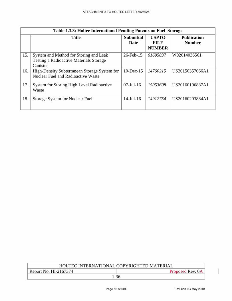
HOLTEC INTERNATIONAL COPYRIGHTED MATERIAL
Report No. HI-2167374 Proposed Rev. 0A
1-36
Table 1.3.3: Holtec International Pending Patents on Fuel Storage
Title Submittal
Date
USPTO
FILE
NUMBER
Publication
Number
15. System and Method for Storing and Leak
Testing a Radioactive Materials Storage
Canister
26-Feb-15 61695837 W02014036561
16. High-Density Subterranean Storage System for
Nuclear Fuel and Radioactive Waste
10-Dec-15 14760215 US20150357066A1
17. System for Storing High Level Radioactive
Waste
07-Jul-16 15053608 US20160196887A1
18. Storage System for Nuclear Fuel 14-Jul-16 14912754 US20160203884A1
ATTACHMENT 3 TO HOLTEC LETTER 5025025
Page 56 of 604 Revision 0C May 2018
HOLTEC INTERNATIONAL COPYRIGHTED MATERIAL
Report No. HI-2167374 Proposed Rev. 0A
1-37
1.4 MATERIAL INCORPORATED BY REFERENCE
Materials incorporated by reference into this report are discussed in Section 1.0 and identified in
Table 1.0.3. The majority of this information is incorporated from the HI-STORM UMAX docket,
with some supplementary information from the HI-STORM FW. Each individual chapter provides
a table which identifies the specific material incorporated by reference into each chapter, with
specific sections and specific references.
ATTACHMENT 3 TO HOLTEC LETTER 5025025
Page 57 of 604 Revision 0C May 2018
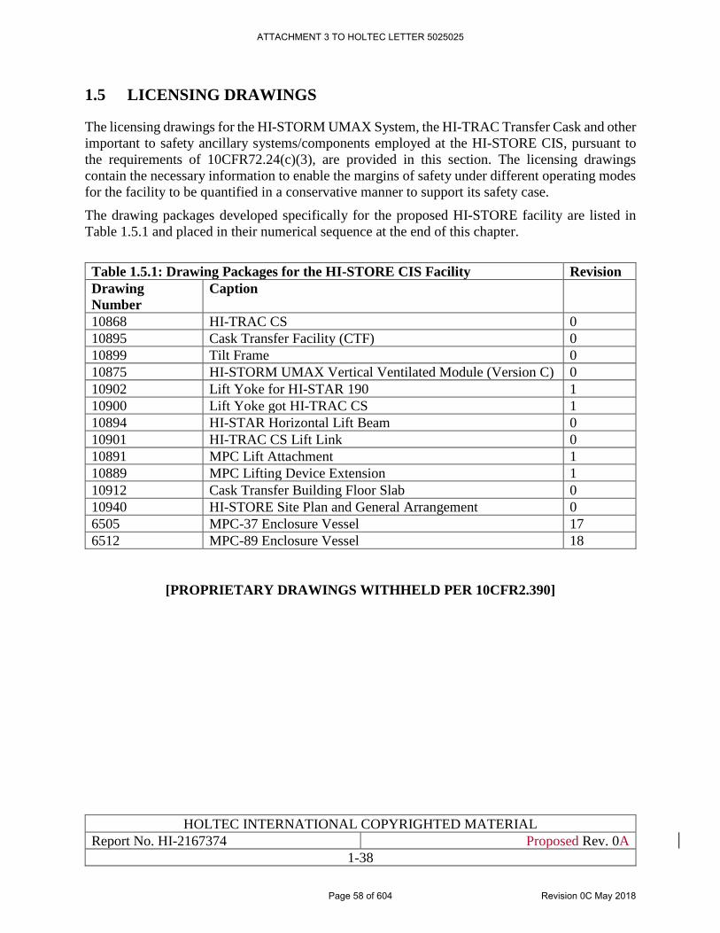
HOLTEC INTERNATIONAL COPYRIGHTED MATERIAL
Report No. HI-2167374 Proposed Rev. 0A
1-38
1.5 LICENSING DRAWINGS
The licensing drawings for the HI-STORM UMAX System, the HI-TRAC Transfer Cask and other
important to safety ancillary systems/components employed at the HI-STORE CIS, pursuant to
the requirements of 10CFR72.24(c)(3), are provided in this section. The licensing drawings
contain the necessary information to enable the margins of safety under different operating modes
for the facility to be quantified in a conservative manner to support its safety case.
The drawing packages developed specifically for the proposed HI-STORE facility are listed in
Table 1.5.1 and placed in their numerical sequence at the end of this chapter.
Table 1.5.1: Drawing Packages for the HI-STORE CIS Facility Revision
Drawing
Number
Caption
10868 HI-TRAC CS 0
10895 Cask Transfer Facility (CTF) 0
10899 Tilt Frame 0
10875 HI-STORM UMAX Vertical Ventilated Module (Version C) 0
10902 Lift Yoke for HI-STAR 190 1
10900 Lift Yoke got HI-TRAC CS 1
10894 HI-STAR Horizontal Lift Beam 0
10901 HI-TRAC CS Lift Link 0
10891 MPC Lift Attachment 1
10889 MPC Lifting Device Extension 1
10912 Cask Transfer Building Floor Slab 0
10940 HI-STORE Site Plan and General Arrangement 0
6505 MPC-37 Enclosure Vessel 17
6512 MPC-89 Enclosure Vessel 18
[PROPRIETARY DRAWINGS WITHHELD PER 10CFR2.390]
ATTACHMENT 3 TO HOLTEC LETTER 5025025
Page 58 of 604 Revision 0C May 2018
HOLTEC INTERNATIONAL COPYRIGHTED MATERIAL
Report No. HI-2167374 Proposed Rev. 0A
1-39
1.6 REGULATORY COMPLIANCE
This section ensures compliance with 10CFR72.18, 72.22, 72.24 and 72.44 as indicated in NUREG
1567 [1.0.3] Section 1.
10CFR72.18 discusses material incorporated by reference, which is discussed in Section 1.4.
10CFR72.22 requires that general and financial information about the applicant is provided,
including age, address, description of business, estimated cost of construction and operation of the
facility and decommissioning, which is discussed in Section 1.3 (with the exception as indicated
below).
10CFR72.24 requires that the application includes technical information, including overview of
the installation, principal characteristics of the ISFSI (dimensions, weights, and construction
materials, licensing drawings), facility allowance for decommissioning (retrievability), and
general description of contents to be stored at the facility. Information regarding facility systems
descriptions and agents and contractors are required to be provided.
10CFR72.44 describes the license conditions, which are provided in the license document for the
facility.
The chapter complies with 10CFR72 requirements above and follows the guidance of NUREG-
1567 [1.0.3] with the following qualifications:
1. For proprietary reasons financial information, including cost of construction, operation and
decommissioning will be submitted separately from this SAR.
2. Due to the significant quantity of material incorporated by reference into this SAR, information
regarding weights will be incorporated by reference into other chapters for analysis purposes. As
such, to maintain adequate configuration control, information on weights will be included in
Chapter 5 (Structural) of this report. Similarly, information on contents to be stored in the HI-
STORM UMAX is provided in Chapter 4 of this report.
ATTACHMENT 3 TO HOLTEC LETTER 5025025
Page 59 of 604 Revision 0C May 2018
HOLTEC INTERNATIONAL COPYRIGHTED MATERIAL
Report No. HI-2167374 Proposed Rev. 0C
2-1
CHAPTER 2: SITE CHARACTERISTICS
2.0 INTRODUCTION
This chapter presents the relevant characteristics of the proposed HI-STORE Consolidated Interim
Storage (CIS) Facility site (Site). The purpose of this chapter is to: (1) characterize local land and
water use and population so that individuals and populations likely to be affected can be identified;
(2) identify the external natural and man-induced phenomena for inclusion in design basis
considerations; and (3) characterize the transport processes which could move any released
contamination from the facility to the maximally exposed individuals and populations. More
details regarding the environmental characteristics of the Site and surroundings is found in the
Environmental Report (ER) [1.0.4].
All references are placed within square brackets in this report and are compiled in Chapter 19 of this report
ATTACHMENT 3 TO HOLTEC LETTER 5025025
Page 60 of 604 Revision 0C May 2018
HOLTEC INTERNATIONAL COPYRIGHTED MATERIAL
Report No. HI-2167374 Proposed Rev. 0C
2-2
2.1 GEOGRAPHY AND DEMOGRAPHY
2.1.1 Site Location
The center of the Site is at latitude 32.583 north and longitude 103.708 west, in Lea County, New
Mexico, 32 miles east of Carlsbad and 34 miles west of Hobbs (Figure 2.1.1). Larger population
centers are Roswell, New Mexico, 74 miles to the northwest; Odessa, Texas, 92 miles to the
southeast; and Midland, Texas, also to the southeast at 103 miles. The nearest international airport
is located between Midland and Odessa, Texas 98 miles to the southeast.
2.1.2 Site Description
The Site is currently owned by the Eddy-Lea Energy Alliance (ELEA), a limited liability company
owned by the cities of Carlsbad and Hobbs, and Eddy County and Lea County. In April 2016,
Holtec and ELEA signed a memorandum of agreement (MOA) [2.1.1] covering the design,
licensing, construction and operation of the Site. Among other things, that MOA provides the terms
by which Holtec could purchase the Site. On July 19, 2016, the New Mexico Board of Finance
approved the sale of the Site to Holtec [2.1.2].
The Site consists of mostly undeveloped land used for cattle grazing with the only boundary being
a four-strand barb wire fence along the south side of the property until it nears Laguna Gatuna,
where it turns south to the highway. This fence is the boundary between two grazing allotments
administered by the Bureau of Land Management (BLM). The majority of allotments are grazed
year-round with some type of rotational grazing. Figure 2.1.2 depicts the Site boundaries.
Rangelands comprise a substantial portion of the Site and provide forage for livestock. Pasture
rotation, with some of the pastures being rested for a least a portion of the growing season, is
standard management practice for grazing allotments. Grazing allotments near the site can be seen
in Figure 2.1.3. Vegetative monitoring studies to collect data on the utilization of the land, and the
amount of precipitation by pasture from each study allotment are conducted annually on Federal
lands to compare production with consumption. Currently, the BLM permits nine animal unit
months1 per 640 acres [2.1.3]. Because the Site is privately held, it does not fall under the BLM
range management rules, although the rules apply to most of the adjacent lands that are managed
by the same rancher.
The following list of structures is shown on Figures 2.1.2, 2.1.13, and 2.1.20. A map of the utility
infrastructure is shown on Figure 2.1.4. An aerial view of the Site is shown in Figure 2.1.5 and
several plot views of the HI-STORE CIS Facility with all Phases complete are shown in Figures
2.1.6(a), (b), and (c).
• A communications tower in the southwest corner of the Site;
• A former producing gas and distillate well is located near the communications tower;
• A small water drinker (livestock) is located along the aqueduct in the northern half of the
Site;
• Oil recovery facility (abandoned) that still has tanks and associated hardware left in place
in the northeast corner;
1 An “animal unit month” is the amount of forage needed to feed a cow for one month.
ATTACHMENT 3 TO HOLTEC LETTER 5025025
Page 61 of 604 Revision 0C May 2018
HOLTEC INTERNATIONAL COPYRIGHTED MATERIAL
Report No. HI-2167374 Proposed Rev. 0C
2-3
• An oil recovery facility with tanks and associated hardware still in place in the far
southwest corner;
• Existing natural gas pipelines run underground along the North-South axis to the East of
the Site;
• A temporary flexible pipeline for natural gas runs aboveground diagonally through the
center of the Site.
As can be seen in Figure 2.1.2, the oil recovery facility that is currently in place in the southwest
corner of the Site is a potential fire hazard to the SSCs of the CIS Facility. Table 2.1.4 lists
conservative values for input parameters used to assess the risk this oil recovery facility poses to
the SSCs of the CIS Facility. A detailed discussion of this evaluation is presented in Subsection
6.5.2.
The natural gas pipelines can be seen in Figures 2.1.13 and 2.1.20. The temporary flexible pipeline
that runs aboveground through the center of the Site will be moved prior to or during the early
construction phases of the CIS Facility. The natural gas pipelines which run along the North-South
axis to the East of the site are underground and not considered to present a threat to the CIS Facility
operations.
No water wells are located on the Site. However, the Site has been associated with oil and gas
exploration and development with at least 18 plugged and abandoned oil and gas wells located on
the property. However, none of these plugged and abandoned oil and gas wells are located within
the area where the ISFSI would be located or where any land would be disturbed and they are not
expected to affect the construction and operation of the CIS Facility. The plugged wells are
estimated to be 30-70 years old. It is possible that hydrocarbon contamination exists at the Site as
a result of these past practices [1.0.4]. There are no active wells on the Site and there are no plans
to use any of the plugged and abandoned wells on the Site.
United States Department of Agriculture (USDA) Natural Resources Conservation Service
(NRCS) Soil Survey Maps of Lea County, NM [2.1.4] were reviewed in order to identify the soil
units present at the Site. A Soil Survey Map is provided as Figure 2.1.7. About 90 percent of the
soils within the Site are classified as Simona-Upton association (SR) and Simona fine sandy loam
(SE). Simona soils are calcareous eolian deposits derived from sedimentary rock and consist of
fine sandy loam underlain by gravelly fine sandy loam and cemented material, and gravelly fine
sandy loam underlain by fine sandy loam and cemented material. The remaining soils
(approximately 10 percent) consist of Midessa and wink fine sandy loam (MN), Mobeetie Potter
Association (MW), Stony rolling land (SY), and Mixed alluvial land (MU). Details regarding the
Site soil types and characteristics were compiled from Appendix D of the ER [1.0.4], and are
summarized below.
Simona-Upton Association (SR)
Simona (50 percent of soil unit)
• 0 to 8 inches: gravelly fine sandy loam; saturated hydraulic conductivity (Ksat) of
14.11 to 42.34 micrometers per second.
• 8 to 16 inches: fine sandy loam; Ksat of 14.11 to 42.34 micrometers per second.
ATTACHMENT 3 TO HOLTEC LETTER 5025025
Page 62 of 604 Revision 0C May 2018
HOLTEC INTERNATIONAL COPYRIGHTED MATERIAL
Report No. HI-2167374 Proposed Rev. 0C
2-4
• 16 to 26 inches: cemented material (Petrocalcic Restrictive Layer i.e. Caliche); Ksat
of 0.00 to 0.42 micrometers per second.
Upton (35 percent of soil unit)
• 0 to 8 inches: gravelly loam; Ksat of 4.23 to 14.11 micrometers per second.
• 8 to 18 inches: cemented material; Ksat of 0.07 to 4.23 micrometers per second.
• 18 to 60 inches: very gravelly loam; Ksat of 4.23 to 14.11 micrometers per second.
Simona fine sandy loam (SE)
• 0 to 8 inches: fine sandy loam; Ksat of 14.11 to 42.34 micrometers per second.
• 8 to 16 inches: gravelly fine sandy loam; Ksat of 14.11 to 42.34 micrometers per
second.
• 16 to 26 inches: cemented material (Petrocalcic Restrictive Layer i.e. Caliche); Ksat
of 0.0 to 0.42 micrometers per second.
Midessa and wink fine sandy loams (MN)
Midessa (45 percent of soil unit)
• 0 to 4 inches: fine sandy loam; Ksat of 14.11 to 42.34 micrometers per second.
• 4 to 22 inches: clay loam; Ksat of 1.35 to 1.55 micrometers per second.
• 22 to 60 inches: clay loam; Ksat of 4.23 to 14.11 micrometers per second.
Wink (40 percent of soil unit)
• 0 to 12 inches: fine sandy loam; Ksat of 14.11 to 43.34 micrometers per second.
• 12 to 23 inches: sandy loam; Ksat of 14.11 to 43.34 micrometers per second.
• 23 to 60 inches: sandy loam; Ksat of 14.11 to 43.34 micrometers per second.
Mobeetie-Potter Association (MW)
Mobeetie (70 percent of soil unit)
• 0 to 4 inches: fine sandy loam; Ksat of 14.11 to 43.34 micrometers per second.
• 4 to 24 inches: fines sandy loam; Ksat of 14.11 to 43.34 micrometers per second.
• 24 to 60 inches: fine sandy loam; Ksat of 14.11 to 43.34 micrometers per second.
Potter (24 percent of soil unit)
• 0 to 4 inches: gravelly fine sandy loam; Ksat of 4.23 to 14.11 micrometers per
second.
• 4 to 14 inches: extremely cobbly loam; Ksat of 4.23 to 42.34 micrometers per
second.
Stony rolling land (SY)
ATTACHMENT 3 TO HOLTEC LETTER 5025025
Page 63 of 604 Revision 0C May 2018
HOLTEC INTERNATIONAL COPYRIGHTED MATERIAL
Report No. HI-2167374 Proposed Rev. 0C
2-5
Torriorthents (85 percent of soil unit)
• 0 to 20 inches: extremely gravelly sandy loam; Ksat of 14.11 to 42.34 micrometers
per second.
• 20 to 60 inches: bedrock; Ksat of 0.42 to 14.00 micrometers per second.
Mixed alluvial land (MU)
Ustifluvents (85 percent of soil unit)
• 0 to 60 inches: stratified sand to loamy fine sand to loam to sandy clay loam to clay
loam to clay; Ksat of 0.42 to 141.14 micrometers per second.
Appendix D of the ER [1.0.4] provides additional information regarding soil descriptions, soil
features, and physical, chemical, and engineering properties, including soil salinity. Laboratory
analyses of soil samples within the Site indicated chloride concentrations of 26-43,000 mg/kg in
the soil [2.1.3]. The soil samples were taken in the eastern portion of the Site, in areas previously
used for oilfield disposal. The highest chloride concentrations are considered to be localized and
not reflective of the concentrations where the CISF would be located [2.1.3]. A review of the
available soil data, including engineering properties of the Site soils, indicates favorable conditions
for foundations, utilities, surface pavement, and other improvements [2.1.3]. Removal of fill would
not induce seismic activity or affect subsurface faults [1.0.4]. Section 4.3 of the ER [1.0.4] provides
additional details regarding the potential impacts of the CIS Facility on soils, including a
discussion of construction activities adjacent to a finished ISFSI structure.
In December of 2017, a site characterization for HI-STORE CISF Phase 1 was completed . The
field explorations included borings and geophysical testing at the HI-STORE site. Figure 2.1.8
shows the location of the 9 borings and ancillary borings. Detailed profiles for these borings can
be found in the Geotechnical Data Report prepared by GEI [2.1.24] or in Sections 2.5 and 2.6 of
this report.
Vegetation and habitats within the Site and immediately surrounding area are common within the
region. The Site does not support any vegetation of significance. Significance is defined in this
document as any plant, animal, or habitat that: (1) has high public interest or economic value or
both; or (2) may be critical to the structure and function of the ecosystem or provide a broader
ecological perspective of the region.
The Project area is in the primary vegetation community of Desert Grasslands, which is widespread
at lower elevations in southern and western New Mexico. These communities are characterized by
significant amounts of grasses and less than 10 percent of total cover being forbs and shrubs
[2.1.5]. Typical vegetation in Desert Grassland communities include black grama
(Bouteloua eriopoda), blue grama (Bouteloua gracilis), bluestem, buffalo grass (Bouteloua
dactyloides), western wheatgrass (Pascopyrum smithii), galletas (Hilaria spp.), tobosa
(Pleuraphis mutica), alkali sacaton (Sporobolus airoides), three-awn (Aristida spp.), mesquite
(Prosopis spp.), serviceberry (Amelanchier denticulate), skunkbush sumac (Rhus trilobata), sand
sagebrush (Artemisia filifolia), Apache plume (Fallugia paradoxa), creosotebush (Larrea
tridentata), and cliffrose (Purshia mexicana). With appropriate moisture (generally more than is
typically experienced) sunflower (Helianthus annuus), croton (Croton spp.), and pigweed
(Amaranthus palmeri) may grow in disturbed or ponded depressions.
ATTACHMENT 3 TO HOLTEC LETTER 5025025
Page 64 of 604 Revision 0C May 2018
HOLTEC INTERNATIONAL COPYRIGHTED MATERIAL
Report No. HI-2167374 Proposed Rev. 0C
2-6
A biological survey in October of 2016 (Appendix B in the ER [1.0.4]) also documented a variety
of mesquite scrubland and very few grassland species. This further indicates that vegetation in the
area has changed from a desert grassland to mesquite scrubland due to overgrazing. The dominant
species documented during this survey include broom snakeweed, honey mesquite, prairie verbena
(Glandularia bipinnatifida), prickly pear (Opuntia engelmannii), scarlet globemallow
(Sphaeralcea coccinea), silverleaf nightshade (Solanum elaeagnifolium), tobosa grass, western
peppergrass (Lepidium montanum), and wooly croton (Croton capitatus).
The topography of the Site shows a high point located on the southern border of the Site and gentle
slopes leading to the two drainages (Laguna Plata and Laguna Gatuna). Both of these drainages
would be able to accept a one day severe storm total within the 7.5 inch range with excess free
board space. The natural drainage of the Site is useful by providing a natural area for impoundment
of excess runoff during severe storms [2.1.3]. Figures 2.1.9 – 2.1.11 depict the topography for the
Site and the surrounding area.
There are no United States Army Corps of Engineers (USACE) jurisdictional wetlands on the Site
[2.1.3]. Additionally, there no floodplains identified or mapped for the Site or Lea County, New
Mexico [2.1.6, 2.1.7].
2.1.3 Population Distribution and Trends
This section describes population distribution and trends for the 50-mile region of influence (ROI)
surrounding the proposed Site including Lea and Eddy Counties in New Mexico and Andrews and
Gaines Counties in Texas (see Figure 2.1.12). Lea County is primarily rural, as are the other
counties in the ROI. Between 2000 and 2010, the population in the ROI has grown at a slower rate
in comparison to New Mexico-wide population growth. Population estimates in the ROI are
projected to grow at a slower rate than New Mexico, increasing 10 percent between 2015 and 2025
while New Mexico is projected to increase 19 percent during the same time period. Table 2.1.1
lists historical population and Table 2.1.2 lists projected population in the ROI and New Mexico
and Texas.
The population in the ROI in 2015 was estimated to be 166,914 [2.1.9]. In 2015, 43 percent of the
population of the ROI resided in Lea County, New Mexico. Between 2010 and 2015, the counties
within the ROI all experienced an increase in population. Gaines County, Texas had the greatest
increase at 14 percent, while Eddy County, New Mexico had the lowest increase at seven percent
during the same time period.
The nearest residence to the Site is the Salt Lake Ranch located 1.5 miles north of the Site. There
are additional residences at the Bingham Ranch, two miles to the south, and near the Controlled
Recovery Inc. complex, three miles to the southwest. There is an average population of less than
20 residents among the five ranches within a six mile radius. This is a population density of less
than 5 residents per square mile [2.1.3]. Table 2.1.3 presents the population density per square
mile of land for the ROI in 2010. Figure 2.1.13 presents a sector map of population in segments
surrounding the Site for distances of 1, 2, 3, 4, and 5 miles. As shown on that Figure, there are
only 9 people living within 5 miles of the proposed Site. As discussed in Section 3.8.1 of the ER,
population estimates in the Region of influence (ROI) are projected to grow at a slower rate than
New Mexico, increasing 10 percent between 2015 and 2025, while New Mexico is projected to
increase 19 percent during the same time period. Assuming a 10 percent growth between 2015 and
ATTACHMENT 3 TO HOLTEC LETTER 5025025
Page 65 of 604 Revision 0C May 2018
HOLTEC INTERNATIONAL COPYRIGHTED MATERIAL
Report No. HI-2167374 Proposed Rev. 0C
2-7
2025, the projected population living within 5 miles of the CIS Facility would grow from 9 to 10
persons.
With regard to transient populations within 5 miles of the CIS Facility, Holtec contacted all
employers within 5 miles and determined that there are currently approximately 303 persons
working within 5 miles of the CIS Facility boundary, broken down as follows:
• Land Farm (R360 Disposal): 1.9 miles southwest of the CIS Facility Site boundary;
43 full time equivalent (FTE) workers;
• Intrepid East Mine: 4.9 miles east of the CIS Facility Site boundary; 210 FTE’s;
• Intrepid North Mine: 4.2 miles west of the CIS Facility Site boundary; 40 FTE’s;
• Caliche Mine: 4 miles southwest of the CIS Facility Site boundary; 10 FTE’s
[2.1.14].
With regard to future projections, there are no reasonably foreseeable projects expected to occur
within 5 miles of the CIS Facility boundary and no changes to the existing transient workforce
were forecast by the employers in the area [2.1.14]. Consequently, it is assumed that the transient
population of 303 workers would remain constant going forward.
The nearest local school facilities, daycare, nursing homes and hospitals are located in Hobbs, NM.
The educational institutions include three colleges, a high school and an alternative high school,
three middle schools, twelve elementary schools, and two private schools. The Lea Regional
Medical Center is the nearest hospital. There are no school facilities or hospitals located within 5
miles of the proposed Site.
Because the only mechanism for radiological exposure would be from radiation (neutrons and
gamma rays) emitted from the storage casks, the highest public dose would result from an
individual located as close to the SNF casks as possible. For details on the radiation protection
evaluation for the Site, see Chapter 11 of this SAR.
2.1.4 Land and Water Use
As shown on Figure 2.1.14 and 2.1.15, almost all of the land immediately surrounding the Site is
owned and managed by the BLM. Land uses in the area are limited to oil and gas exploration and
production, oil and gas related services industries, livestock grazing, and limited recreational
activity. Lands within six miles of the Site are privately owned, state lands, or BLM lands. Land
use within six miles of the Site falls into two categories; livestock grazing and mineral extraction.
Within 50 miles of the Site, except for the communities located in the area, the land use and
ownership is essentially the same as within the six mile radius. Along with the mining, grazing,
and oil/gas activity, agriculture is a major activity [2.1.3].
Lea County is approximately 2.8 million acres in size. Property ownership is 17 percent Federal
government, 31 percent state government, and 52 percent private. The Federally-owned land is
primarily located in the southwestern portion of the county, the state-owned land is predominately
located throughout the middle, and the privately owned land primarily extends from north to south
in the county’s eastern portion. Large tracts of land in Lea County are privately owned by farmers,
ranchers, oil, gas, and mining companies. Urbanized areas near cities and towns include ownership
of smaller tracts of land for residential, municipal, and commercial purposes. Approximately 93
ATTACHMENT 3 TO HOLTEC LETTER 5025025
Page 66 of 604 Revision 0C May 2018
HOLTEC INTERNATIONAL COPYRIGHTED MATERIAL
Report No. HI-2167374 Proposed Rev. 0C
2-8
percent of Lea County is used as range land for grazing, and approximately 4 percent is used for
crop farming. Urban areas and the roadway system account for the remaining land use. Most of
the land actively farmed in Lea County is irrigated [2.1.15].
Mineral extraction in the area consists of underground potash mining and oil/gas extraction. Both
industries support major facilities on the surface, although mining surface facilities are confined
to a fairly small area. Intrepid Mining LLC (Intrepid) owns two potash mines located within 6
miles of the Site. The Intrepid North mine, located nearly 6 miles to the west, is no longer actively
mining potash underground. However, the surface facilities are still being used in the manufacture
of potash products. The Intrepid East facility is still mining its underground potash ore [2.1.3];
however, it too is nearly 6 miles to the southwest of the site. Mineral resources near the Site, as
determined from the USGS Mineral Resources Data System and the New Mexico Mining Minerals
Division, are mapped on Figure 2.1.12. The USGS and NM MMD databases indicate that the CIS
Facility is not co-located with existing mining facilities.
Potash was discovered in southeastern New Mexico in 1925 in a well that was being drilled for oil
and gas. By the mid-1930s, there were 11 companies exploring for potash in southeastern New
Mexico. The potash in southeastern New Mexico has been a major potash resource. The remaining
potash reserves are estimated to be 500 million tons. Potash production continues in the Delaware
Basin with active mining by Intrepid Mining and Mosaic Co. Although much of the high-grade
zones have been mined out, exploration for commercially viable deposits continues [2.1.16].
Conventional mechanized underground mining operations are the most widely used method for
the extraction of potash ore. A variety of mining techniques and equipment may be employed
depending on factors such as: the orebody depth, geometry, thickness and consistency, the
geological and geotechnical conditions of the ore and surrounding rock, and the presence of
overlying aquifers. Methods in widespread use include variations of room and pillar, longwall, cut
and fill, and open slope techniques. After the ore is extracted, it is generally transferred by bridge
conveyor, shuttle cars or load-haul-dump units to a system of conveyors that carry it to
underground storage bins, prior to haulage to the surface through a shaft by automated skips. On
rare occasions shallow mines may use a decline and conveyor arrangement [2.1.20].
In general, potash ore zones are nearly flat lying; the potash ore is mined with slightly modified
conventional coal-mining equipment. Room and pillar workings are commonly 6 feet high; as
much as 60-70 percent of the ore is removed during the first stage of mining. Some operations also
use a second “pillar-robbing” mining technique, allowing overlying rock to settle slowly. In this
manner, as much as 92 percent of the ore may be removed [2.1.20, 2.1.16].
When the potash to be extracted is at a depth of 3,000 feet or deeper and/or the potash it is located
in sedimentary rock then solution mining provides a cost effective, efficient and safe way to extract
the resource. Conventional mining involves extracting a lot of rock material to access the mineral
resource resulting in large underground caverns and this excess waste material must also be stored
on surface. With solution mining, a brine is heated and injected into the deposit to dissolves the
potash. The potash-rich brine is then pumped out of the cavern to the surface where the water is
evaporated. Solution mining is currently used at a number of operations in New Mexico, and
ATTACHMENT 3 TO HOLTEC LETTER 5025025
Page 67 of 604 Revision 0C May 2018
HOLTEC INTERNATIONAL COPYRIGHTED MATERIAL
Report No. HI-2167374 Proposed Rev. 0C
2-9
Intrepid Potash was recently approved to conduct solution mining of potash minerals in order to
extract some of the remaining ore from suspended mines in the main potash mining area [2.1.16].
Subsidence is the phenomenon or response that occurs when an underground opening is created.
In the Delaware Basin, subsidence caused by human activities largely has occurred as a result of
potash mining and activities involving the withdrawal or injection of fluids for oil and gas
production and brine extraction. Subsidence from mining creates voids that cause collapse of strata
above the mining level. The overlying and surrounding rock or soil naturally deforms in an effort
to arrive at a new and more stable overall equilibrium position. This equilibrium-seeking action
can result in both vertical and horizontal ground movement, and, if not controlled or minimized,
can cause damage to both surface and subsurface structures. It can result in the development of
undesirable surface topography, such as surface cracking or collapse, sinkholes, blocking or
changing stream channels, and modification of drainage pathways. The rate of subsidence is
largely dependent on the type of material being mined and the amount of material mined [2.1.16].
The magnitude, rate of development, and surface expression of the subsidence process are
controlled by several factors, most of which are interdependent. These include mining method,
depth of extraction, size and configuration of openings, rate of advance or extraction, seam
thickness, topography, lithology, structure, hydrology, in situ stresses, and rock strength and
deformational properties. Taken collectively, they demonstrate the complexity of the subsidence
process [2.1.22].
Subsidence is expected in areas where 90 percent extraction rates occur with the room-and-pillar
mining technique typically used in potash mining. Subsidence is not expected where 60-70 percent
extraction rates are employed (e.g., first stage potash mining). The amount of subsidence is similar
to findings concerning historic potash mining in the area where, given an average 6-feet mining
extraction height, the maximum subsidence was found to be a nominal 4 feet. Subsidence fractures
have been observed in the land surface above workings that have collapsed at depths of 1,000 feet
or more [2.1.16].
As a general rule, the amount of maximum subsidence (i.e., the depth of subsidence) that could
occur cannot exceed the thickness of the zone of mineral extracted (the mining thickness).
Maximum subsidence depth, however, is seldom observed, due to one or more of the following
reasons:
• Because subsidence actually spreads over an area somewhat larger than the mined
area, the subsidence is proportionally less.
• Convergence, or closure of the mined area, is never fully complete or total, so some
voids inevitably remain, reducing the amount of subsidence.
• The overlying rocks expand slightly in volume due to breakage as the ground moves
downward into the mined area, resulting in a “bulking” effect, which contributes to a
reduction in subsidence volume and depth.
• The subsidence process can be slow for rocks that creep—several hundred (or more)
years may be required for ultimate subsidence to occur [2.1.16].
ATTACHMENT 3 TO HOLTEC LETTER 5025025
Page 68 of 604 Revision 0C May 2018
HOLTEC INTERNATIONAL COPYRIGHTED MATERIAL
Report No. HI-2167374 Proposed Rev. 0C
2-10
It is important to note that both historic data and anecdotal evidence suggest that for the
southeastern New Mexico potash mines, virtual completion of the maximum surface subsidence
profile occurs within just a few years (5 to 7 years) after completion of mining [2.1.16].
In some instances, surface subsidence induced by underground mining may alter river and stream
drainage patterns, disrupt overlying aquifers, and damage buildings and infrastructure. The degree
of subsidence depends on factors such as orebody thickness and geometry, the thickness of the
overlying rock and the amount of ore recovered. The effects of subsidence have been reduced to
some extent, through either: (1) the design of the ore extraction layout so as to reduce the rate and
extent of subsidence, or (2) by backfilling openings with processing wastes such as salt tailings, to
reduce or prevent subsidence [2.1.21].
Figure 2.1.17 shows potash that has been historically mined within 6 miles of the proposed CIS
Facility. As shown on that figure, the nearest mined potash is approximately 2 miles from the
southwestern boundary of the CIS Facility Site. However, no active potash mines are within 4.2
miles of the Site. Per Mr. Robert Baldridge, Operations Manager for Intrepid Potash, potash mines
in the area are generally a maximum of approximately 1,800-3,000 feet in depth, and the thickness
of the zone of mineral extracted is a fraction of this total depth [2.1.19]. According to Golder and
Associates, “the zone of disturbance of strata above the mine workings extends beyond the limit
of the mine workings and data from the southeast New Mexico potash fields suggest that a
reasonable limit for defining this zone of disturbance would be an angle of 45 degrees from the
vertical” [2.1.18]. Consequently, for potash mining at a nominal 3,000-feet depth, the subsidence
effects area could extend 3,000 feet beyond the edge of the mine workings [2.1.18]. Given that
the nearest historic potash mine is approximately 2 miles away from the CIS Facility, subsidence
effects at the CIS Facility Site from past or current potash mines would not be expected to occur.
With regard to the nearest potash mine (the National Potash Mine, located approximately 4.2 miles
west of the Site, and shown on Figure 2.2.1 of the SAR), no deep mining has occurred at that mine
since 1982. Given that surface subsidence generally occurs within 5 to 7 years after completion
of mining, no further subsidence from that mine is expected. That mine is considered a surface
facility and is used by Intrepid Potash as a warehouse and distribution center [2.1.19].
With regard to potential future potash mining near the CIS Facility, Figures 2.1.18 and 2.1.19 show
the locations of potash core holes and potash leases within 6 miles of the CIS Facility Site. As
shown on those figures, numerous potash core holes have been drilled in the areas surrounding the
CIS Facility and there are potash leases surrounding the CIS Facility Site. As previously stated in
Section 2.6.4 of the SAR, with regard to potential future drilling on the Site, Holtec has an
agreement with Intrepid Mining LLC (Intrepid) such that Holtec controls the mineral rights on the
Site and Intrepid will not conduct any potash mining on the Site.
Oil in southeastern New Mexico was discovered in 1909, 8 miles south of Artesia, but the well
was never completed as a producer due to mechanical problems. Oil and gas production began in
the New Mexico portion of the Delaware Basin in 1924 with the discovery of the Dayton-Artesia
Field. Until the year 2000, 4.5 billion barrels of oil had been produced mainly from fields on the
Northwest Shelf and Central Platform areas in the Delaware Basin. More than 3.5 billion barrels
of the total production was extracted from Permian-age rocks. The U.S. Geological Survey
(USGS) estimates that the greater Permian Basin area, including parts of southeastern New Mexico
ATTACHMENT 3 TO HOLTEC LETTER 5025025
Page 69 of 604 Revision 0C May 2018
HOLTEC INTERNATIONAL COPYRIGHTED MATERIAL
Report No. HI-2167374 Proposed Rev. 0C
2-11
and west Texas, contains substantial undiscovered oil and gas resources on the order of 1.3 billion
barrels of oil and 41 trillion cubic feet of gas [2.1.16].
As a precaution for the potash mines in this region, the mining companies historically left
protection pillars around the oil and gas boreholes. Well casing corrosion is a common problem in
the Delaware Basin, caused by contact with the brine fluids being withdrawn or injected depending
on the purpose of the well. There are documented cases where escape of unsaturated brines and
dissolution of salt formations caused catastrophic collapse to the surface, not only in the Delaware
Basin, but in other basins having substantial thicknesses of salt layers and numerous wells
penetrating the salt for the purpose of fluid withdrawal [2.1.16].
Thousands of wells have been drilled through evaporate formations in the Delaware Basin to
explore for and produce oil and gas (see Figure 2.1.20, which depicts wells immediately
surrounding the CIS Facility) Because of the extent of the evaporites (salt and anhydrite), drilling
and completion operations have to be conducted in a manner that prevents the dissolution of the
salt and protects the well during drilling and through the productive lives of the wells, often 20 to
30 years or more. Oil and gas exploration targets range from relatively shallow oil and gas at
5,000 feet deep in the Delaware Canyon Formation to deep gas targets in middle Paleozoic
formations in excess of 16,000 feet deep [2.1.16].
Salt can be extracted from subsurface formations by using wells that inject fresh water to dissolve
the salt followed by extraction of the saturated water. In the Delaware Basin, these wells are
referred to as brine wells. Brine wells in the Delaware Basin are used to extract saline water for
use in oil and gas well drilling and workover fluids. Recently, a few brine wells in Eddy County
that were 200 to 300 feet in diameter and 100 to 200 feet deep suffered catastrophic collapse
causing sinkhole development at the surface. Each of the wells associated with the collapse were
former oil and gas wells converted to brine wells. At one brine well in Carlsbad, New Mexico,
geophysical surveys indicated the presence of subsurface fracturing, cavities, and collapse, but no
surface manifestation of collapse has occurred other than tilting of the ground surface [2.1.16].
There are several examples in the Permian Basin of catastrophic subsidence as a result of suspected
oil field casing corrosion and dissolution of salt. The examples of subsidence associated with oil
and gas operations include the Wink Sinks I and II and the Jal Sink. There are other similar
incidents that occurred in areas underlain by salt in Texas and in Kansas. The Wink Sinks
developed in the Hendrick oil field in Winkler County, Texas, near the town of Wink, which is
approximately 75 miles southeast of the proposed CIS Facility Site. Wink Sink I developed in
1980 and Wink Sink II occurred in 2002 [2.1.16].
The Jal sinkhole, which developed in 2001, is located about 8 miles northwest of Jal, New Mexico
and approximately 50 miles southeast of the proposed CIS facility Site. The geologic settings of
the Wink and Jal sinkholes are similar to that of the CIS Facility Site as they occurred at the basin
margin above the Capitan Reef. In each incident, sinkholes formed around a well location and the
sinks had diameters ranging from 200 to over 700 feet. Although the exact cause of development
of these sinkholes is not known, it is suspected that casing failure allowed unsaturated water to
come into contact with, and subsequently dissolve, salt layers [2.1.16]. Potash deposits are located
around and within the Site as shown on Figure 2.1.21. With regard to potential future drilling on
the Site, Holtec has an agreement [2.6.9] with Intrepid such that Holtec controls the mineral rights
ATTACHMENT 3 TO HOLTEC LETTER 5025025
Page 70 of 604 Revision 0C May 2018
HOLTEC INTERNATIONAL COPYRIGHTED MATERIAL
Report No. HI-2167374 Proposed Rev. 0C
2-12
on the Site and Intrepid will not conduct any potash mining on the Site. An area for a potash mine
nearby and west of the Site has been identified as shown on Figure 2.1.21; while the operational
and construction footprint for the CIS Facility does not intersect the area for the potash mine
(identified on Figure 2.1.21 as “Belco shallow” and “Belco deep” potash drill islands), the
proposed railroad spur has the potential to cross these drill islands.
The Belco Shallow and Belco Deep drill islands are located approximately 0.25 and 0.5 miles,
respectively, from the CIS Facility Site boundary, and are intended to accommodate multiple oil
and gas well locations, all or most of which will be horizontal wells completed below the Bone
Springs formation (7,800 feet below the ground surface. Oil and gas drilling has occurred on those
drill islands in the past and could be used in the future. Similarly, as shown on Figure 2.1.20, oil
and gas wells have been drilled in the Green Frog Café Drill Island located just east of the proposed
CIS Facility [2.1.17]. Water demand in Lea County increased 33 percent from 1985 to 1995 and
in 1998, the demand was about 189,000 acre-feet per year. Similar increases in water use from
1985 to 1995 occurred in Irrigated Agriculture (33 percent) Public Supply (26 percent), Domestic
(40 percent), Livestock (106 percent) and Commercial (21 percent) use categories. The water use
by category, as a percentage of Lea County’s total, is 78 percent Irrigated Agricultural, 10 percent
for Public Water Supply, 7 percent Mining, and 3 percent Power. Present water use by Domestic,
Livestock, Commercial Reservoir Evaporation, and Recreation uses are all less than 1 percent of
the total use [2.1.15].
The largest water use in Lea County is for non-municipal irrigation. The New Mexico Office of
the State Engineer (NMOSE) has on record a total of 2,007 non-municipal wells with an associated
water right of 344,600 acre-feet. The next largest user group is municipalities, with water rights of
48,000 acre-feet). The city of Hobbs is the largest water-rights holder with water rights of 20,100
acre-feet per year [2.1.15].
Over the next 40 years, if unrestrained, the water use in Lea County is estimated to increase to
approximately 360,000 acre-feet, 90 percent greater than the 1995 total. The largest part of this
increase is anticipated to come from Irrigated Agricultural, which is projected to require 290,000
acre-feet in 2040, in response to demands for feed from Lea County’s expanding dairy industry.
All other water use categories are expected to increase in Lea County over the next 40 years.
Specifically, 55 percent Public Supply, 58 percent Domestic, 364 percent Livestock, 58 percent
Commercial, 134 percent Industrial, 32 percent Mining, 57 percent Power, and 55 percent
Recreation are estimated above 1995 uses. These other categories account for a total of
approximately 70,000 acre-feet per year of the total annual 2040 estimate [2.1.15].
ATTACHMENT 3 TO HOLTEC LETTER 5025025
Page 71 of 604 Revision 0C May 2018
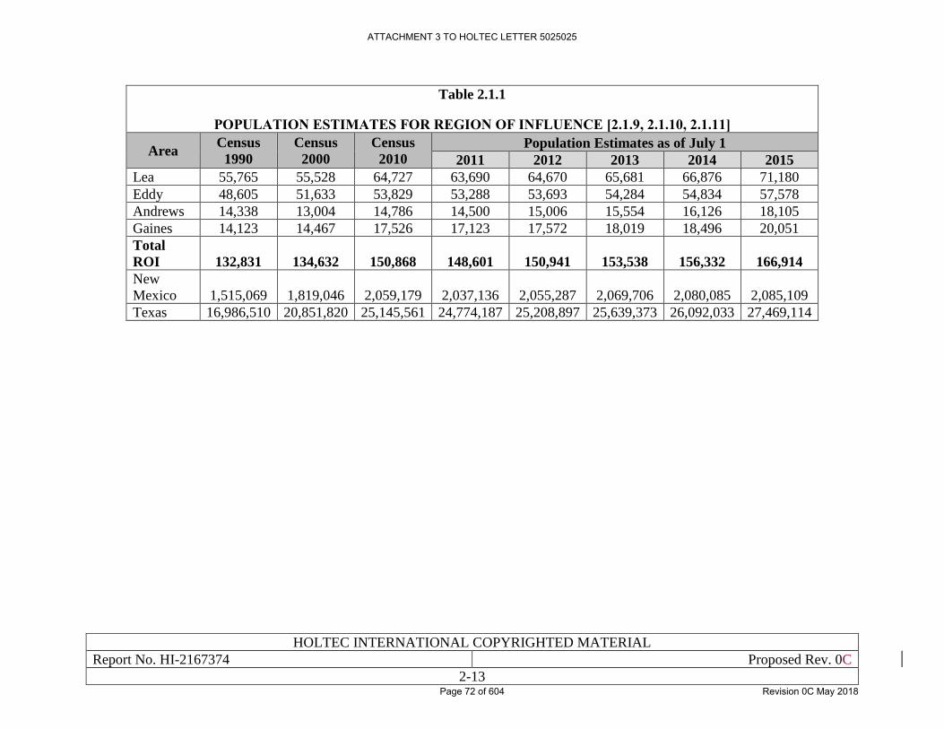
HOLTEC INTERNATIONAL COPYRIGHTED MATERIAL
Report No. HI-2167374 Proposed Rev. 0C
2-13
Table 2.1.1
POPULATION ESTIMATES FOR REGION OF INFLUENCE [2.1.9, 2.1.10, 2.1.11]
Area Census
1990
Census
2000
Census
2010
Population Estimates as of July 1
2011 2012 2013 2014 2015
Lea 55,765 55,528 64,727 63,690 64,670 65,681 66,876 71,180
Eddy 48,605 51,633 53,829 53,288 53,693 54,284 54,834 57,578
Andrews 14,338 13,004 14,786 14,500 15,006 15,554 16,126 18,105
Gaines 14,123 14,467 17,526 17,123 17,572 18,019 18,496 20,051
Total
ROI 132,831 134,632 150,868 148,601 150,941 153,538 156,332 166,914
New
Mexico 1,515,069 1,819,046 2,059,179 2,037,136 2,055,287 2,069,706 2,080,085 2,085,109
Texas 16,986,510 20,851,820 25,145,561 24,774,187 25,208,897 25,639,373 26,092,033 27,469,114
ATTACHMENT 3 TO HOLTEC LETTER 5025025
Page 72 of 604 Revision 0C May 2018
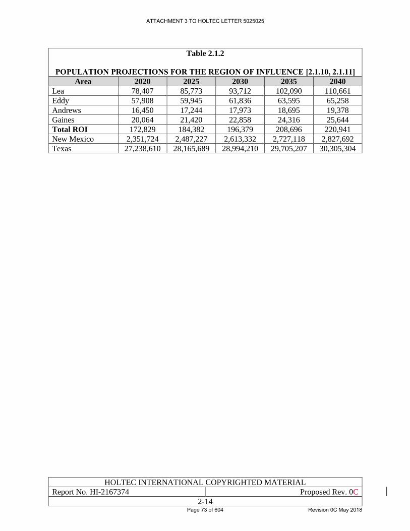
HOLTEC INTERNATIONAL COPYRIGHTED MATERIAL
Report No. HI-2167374 Proposed Rev. 0C
2-14
Table 2.1.2
POPULATION PROJECTIONS FOR THE REGION OF INFLUENCE [2.1.10, 2.1.11]
Area 2020 2025 2030 2035 2040
Lea 78,407 85,773 93,712 102,090 110,661
Eddy 57,908 59,945 61,836 63,595 65,258
Andrews 16,450 17,244 17,973 18,695 19,378
Gaines 20,064 21,420 22,858 24,316 25,644
Total ROI 172,829 184,382 196,379 208,696 220,941
New Mexico 2,351,724 2,487,227 2,613,332 2,727,118 2,827,692
Texas 27,238,610 28,165,689 28,994,210 29,705,207 30,305,304
ATTACHMENT 3 TO HOLTEC LETTER 5025025
Page 73 of 604 Revision 0C May 2018
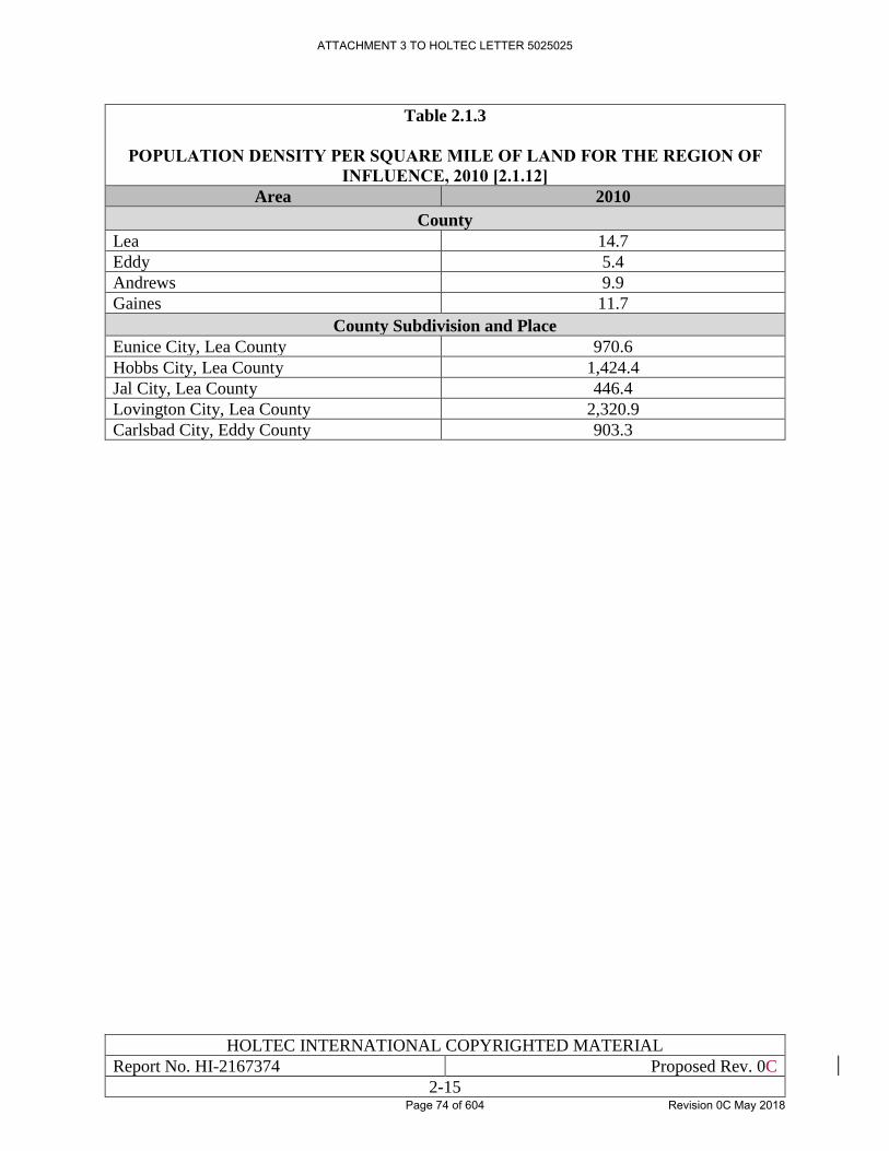
HOLTEC INTERNATIONAL COPYRIGHTED MATERIAL
Report No. HI-2167374 Proposed Rev. 0C
2-15
Table 2.1.3
POPULATION DENSITY PER SQUARE MILE OF LAND FOR THE REGION OF
INFLUENCE, 2010 [2.1.12]
Area 2010
County
Lea 14.7
Eddy 5.4
Andrews 9.9
Gaines 11.7
County Subdivision and Place
Eunice City, Lea County 970.6
Hobbs City, Lea County 1,424.4
Jal City, Lea County 446.4
Lovington City, Lea County 2,320.9
Carlsbad City, Eddy County 903.3
ATTACHMENT 3 TO HOLTEC LETTER 5025025
Page 74 of 604 Revision 0C May 2018
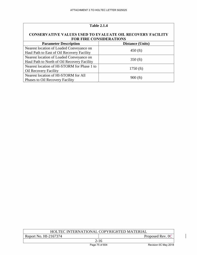
HOLTEC INTERNATIONAL COPYRIGHTED MATERIAL
Report No. HI-2167374 Proposed Rev. 0C
2-16
Table 2.1.4
CONSERVATIVE VALUES USED TO EVALUATE OIL RECOVERY FACILITY
FOR FIRE CONSIDERATIONS
Parameter Description Distance (Units)
Nearest location of Loaded Conveyance on
Haul Path to East of Oil Recovery Facility 450 (ft)
Nearest location of Loaded Conveyance on
Haul Path to North of Oil Recovery Facility 350 (ft)
Nearest location of HI-STORM for Phase 1 to
Oil Recovery Facility 1750 (ft)
Nearest location of HI-STORM for All
Phases to Oil Recovery Facility 900 (ft)
ATTACHMENT 3 TO HOLTEC LETTER 5025025
Page 75 of 604 Revision 0C May 2018
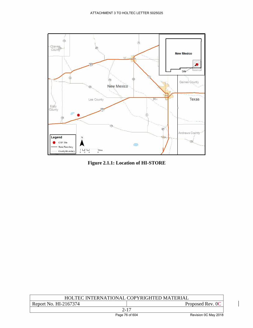
HOLTEC INTERNATIONAL COPYRIGHTED MATERIAL
Report No. HI-2167374 Proposed Rev. 0C
2-17
Figure 2.1.1: Location of HI-STORE
ATTACHMENT 3 TO HOLTEC LETTER 5025025
Page 76 of 604 Revision 0C May 2018
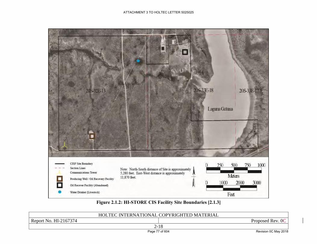
HOLTEC INTERNATIONAL COPYRIGHTED MATERIAL
Report No. HI-2167374 Proposed Rev. 0C
2-18
Figure 2.1.2: HI-STORE CIS Facility Site Boundaries [2.1.3]
ATTACHMENT 3 TO HOLTEC LETTER 5025025
Page 77 of 604 Revision 0C May 2018
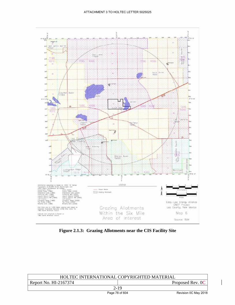
HOLTEC INTERNATIONAL COPYRIGHTED MATERIAL
Report No. HI-2167374 Proposed Rev. 0C
2-19
Figure 2.1.3: Grazing Allotments near the CIS Facility Site
ATTACHMENT 3 TO HOLTEC LETTER 5025025
Page 78 of 604 Revision 0C May 2018
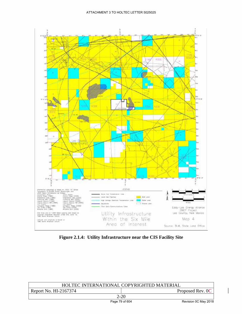
HOLTEC INTERNATIONAL COPYRIGHTED MATERIAL
Report No. HI-2167374 Proposed Rev. 0C
2-20
Figure 2.1.4: Utility Infrastructure near the CIS Facility Site
ATTACHMENT 3 TO HOLTEC LETTER 5025025
Page 79 of 604 Revision 0C May 2018
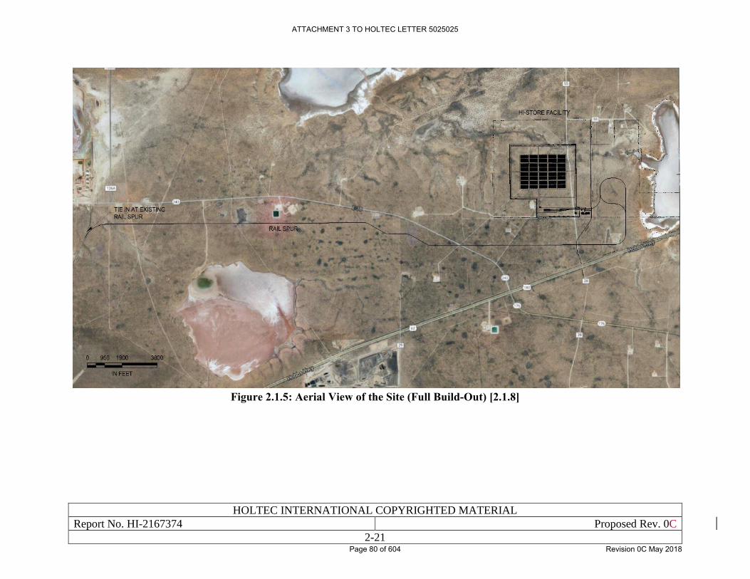
HOLTEC INTERNATIONAL COPYRIGHTED MATERIAL
Report No. HI-2167374 Proposed Rev. 0C
2-21
Figure 2.1.5: Aerial View of the Site (Full Build-Out) [2.1.8]
ATTACHMENT 3 TO HOLTEC LETTER 5025025
Page 80 of 604 Revision 0C May 2018
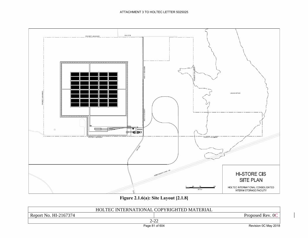
HOLTEC INTERNATIONAL COPYRIGHTED MATERIAL
Report No. HI-2167374 Proposed Rev. 0C
2-22
Figure 2.1.6(a): Site Layout [2.1.8]
ATTACHMENT 3 TO HOLTEC LETTER 5025025
Page 81 of 604 Revision 0C May 2018
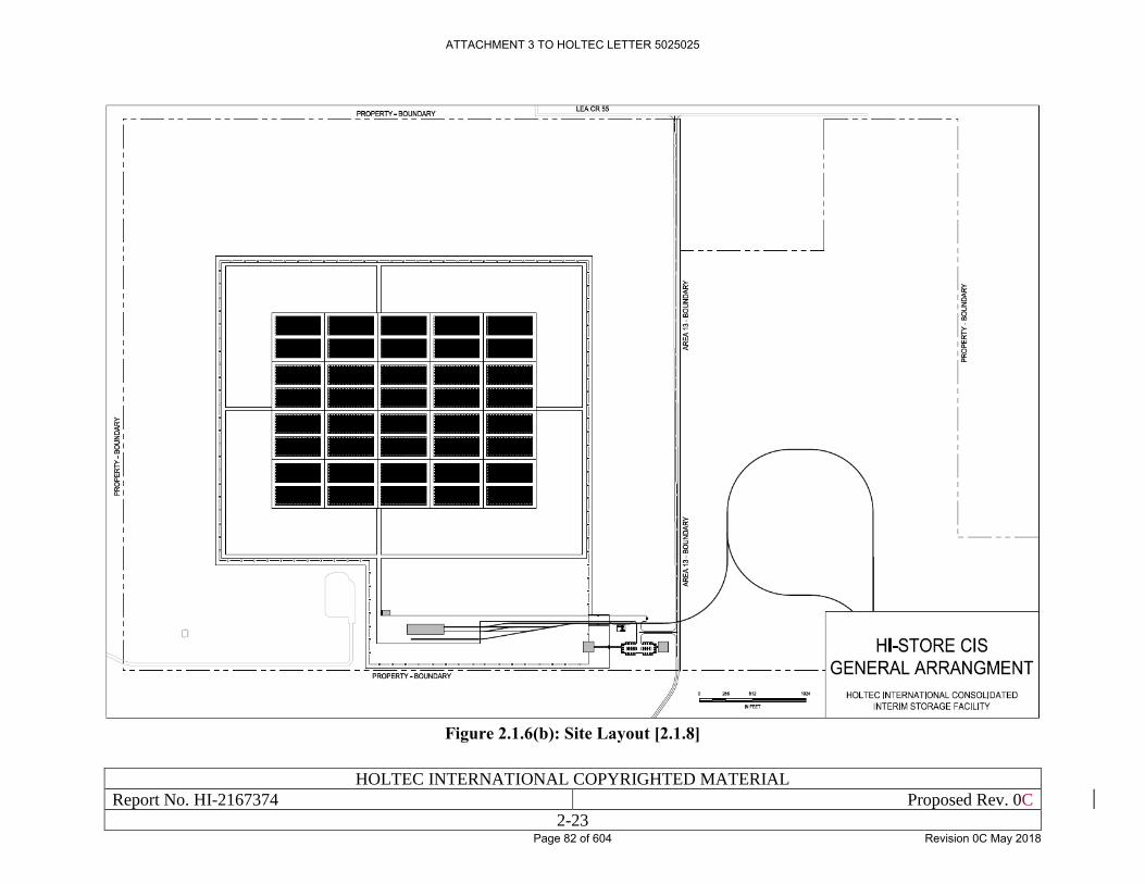
HOLTEC INTERNATIONAL COPYRIGHTED MATERIAL
Report No. HI-2167374 Proposed Rev. 0C
2-23
Figure 2.1.6(b): Site Layout [2.1.8]
ATTACHMENT 3 TO HOLTEC LETTER 5025025
Page 82 of 604 Revision 0C May 2018
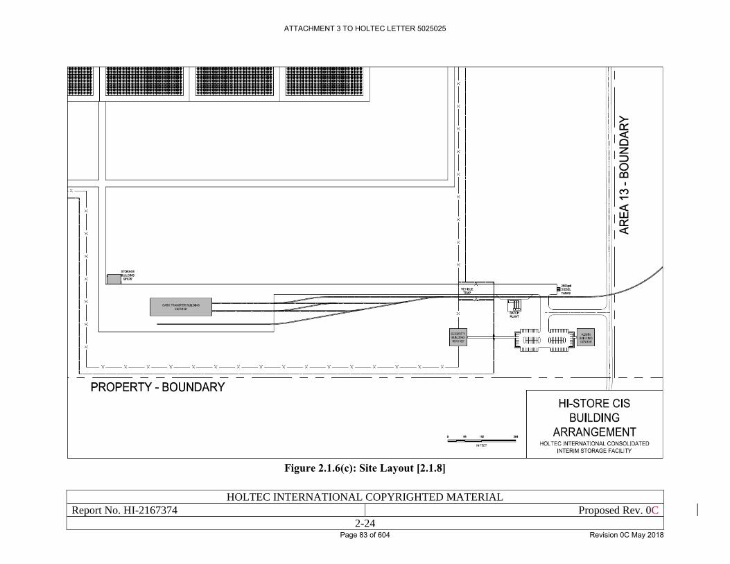
HOLTEC INTERNATIONAL COPYRIGHTED MATERIAL
Report No. HI-2167374 Proposed Rev. 0C
2-24
Figure 2.1.6(c): Site Layout [2.1.8]
ATTACHMENT 3 TO HOLTEC LETTER 5025025
Page 83 of 604 Revision 0C May 2018
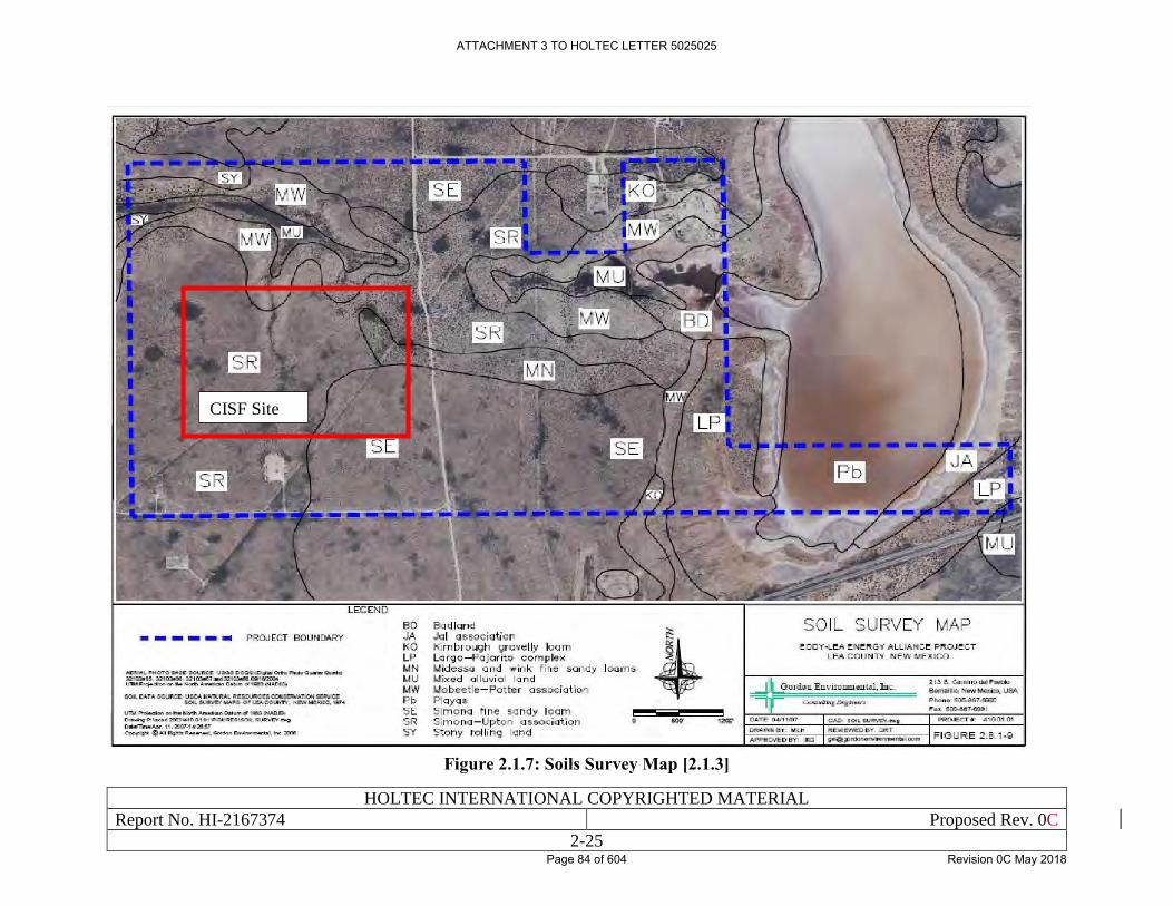
HOLTEC INTERNATIONAL COPYRIGHTED MATERIAL
Report No. HI-2167374 Proposed Rev. 0C
2-25
Figure 2.1.7: Soils Survey Map [2.1.3]
CISF Site
ATTACHMENT 3 TO HOLTEC LETTER 5025025
Page 84 of 604 Revision 0C May 2018
HOLTEC INTERNATIONAL COPYRIGHTED MATERIAL
Report No. HI-2167374 Proposed Rev. 0C
2-26
Figure 2.1.8: Phase 1 Boring Location Map [2.1.24]
ATTACHMENT 3 TO HOLTEC LETTER 5025025
Page 85 of 604 Revision 0C May 2018
Security-Related Information Withheld Under 10 CFR 2.390
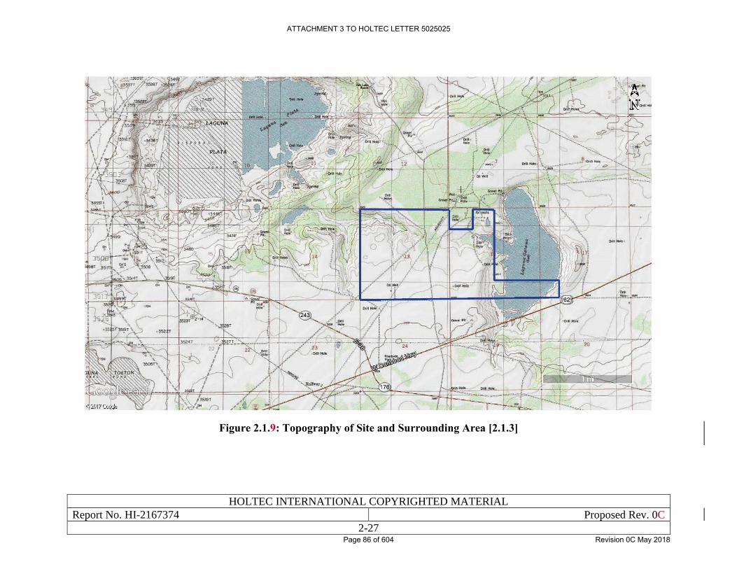
HOLTEC INTERNATIONAL COPYRIGHTED MATERIAL
Report No. HI-2167374 Proposed Rev. 0C
2-27
Figure 2.1.9: Topography of Site and Surrounding Area [2.1.3]
ATTACHMENT 3 TO HOLTEC LETTER 5025025
Page 86 of 604 Revision 0C May 2018
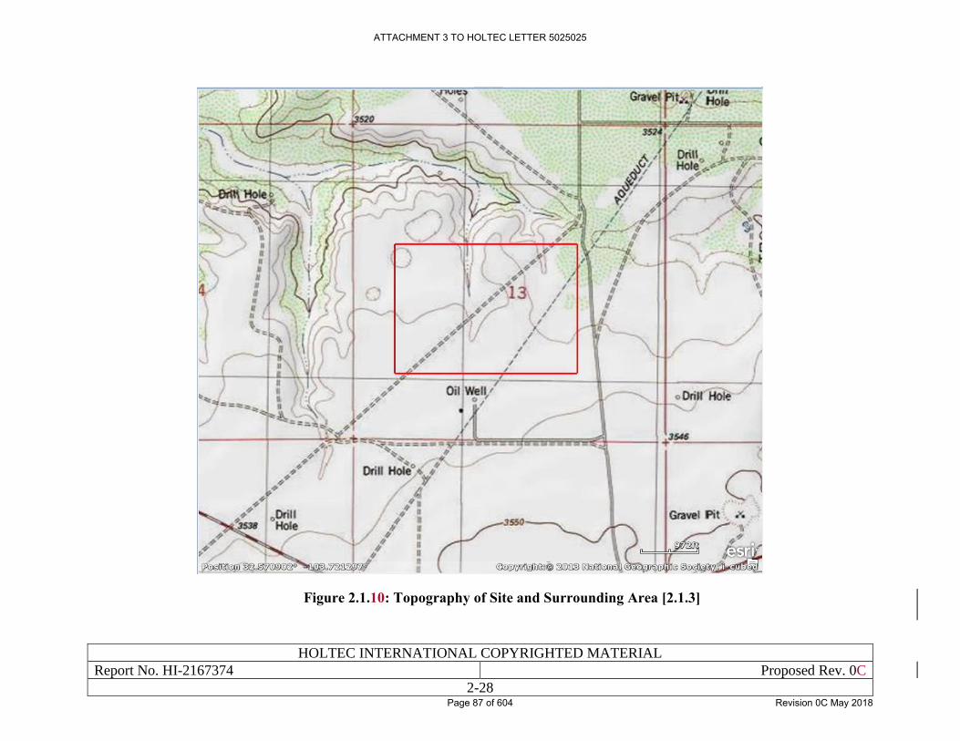
HOLTEC INTERNATIONAL COPYRIGHTED MATERIAL
Report No. HI-2167374 Proposed Rev. 0C
2-28
Figure 2.1.10: Topography of Site and Surrounding Area [2.1.3]
ATTACHMENT 3 TO HOLTEC LETTER 5025025
Page 87 of 604 Revision 0C May 2018
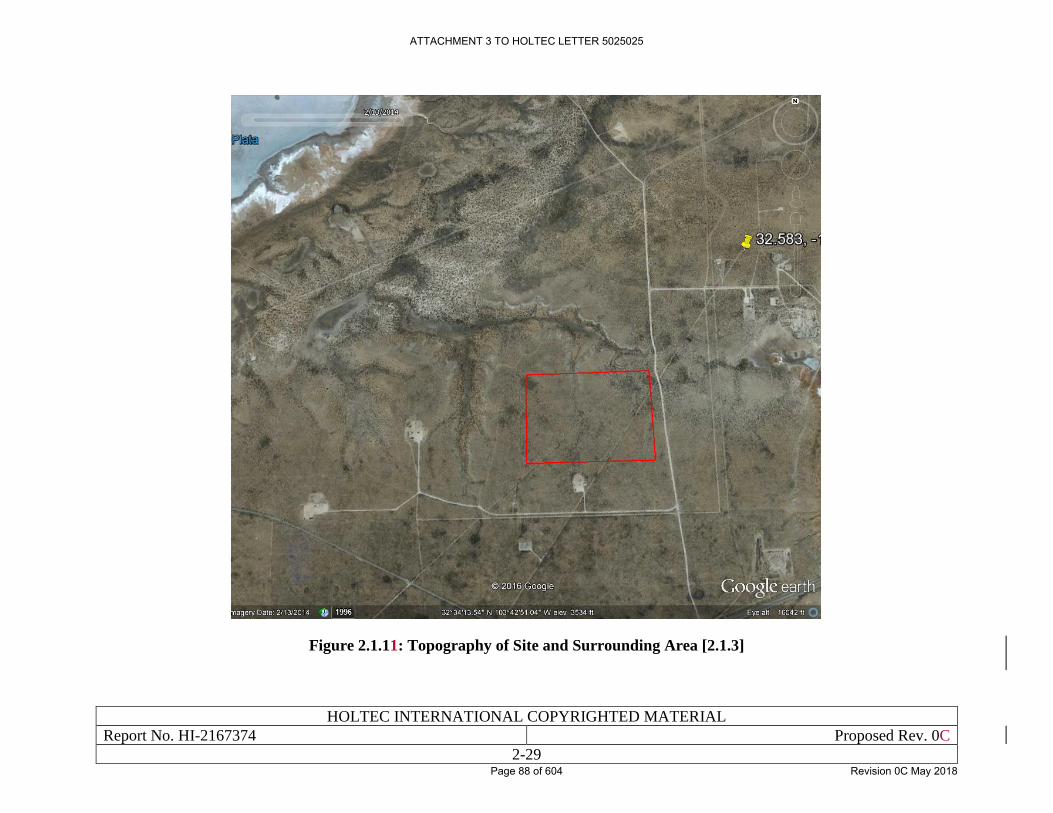
HOLTEC INTERNATIONAL COPYRIGHTED MATERIAL
Report No. HI-2167374 Proposed Rev. 0C
2-29
Figure 2.1.11: Topography of Site and Surrounding Area [2.1.3]
ATTACHMENT 3 TO HOLTEC LETTER 5025025
Page 88 of 604 Revision 0C May 2018
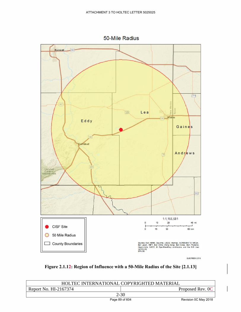
HOLTEC INTERNATIONAL COPYRIGHTED MATERIAL
Report No. HI-2167374 Proposed Rev. 0C
2-30
Figure 2.1.12: Region of Influence with a 50-Mile Radius of the Site [2.1.13]
ATTACHMENT 3 TO HOLTEC LETTER 5025025
Page 89 of 604 Revision 0C May 2018
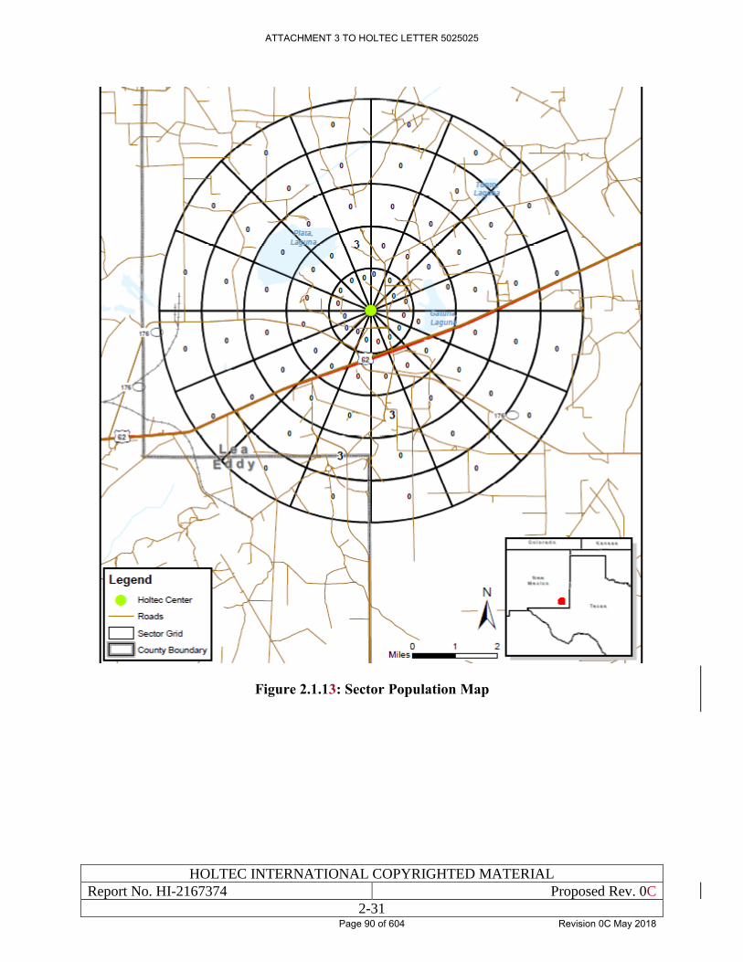
HOLTEC INTERNATIONAL COPYRIGHTED MATERIAL
Report No. HI-2167374 Proposed Rev. 0C
2-31
Figure 2.1.13: Sector Population Map
ATTACHMENT 3 TO HOLTEC LETTER 5025025
Page 90 of 604 Revision 0C May 2018
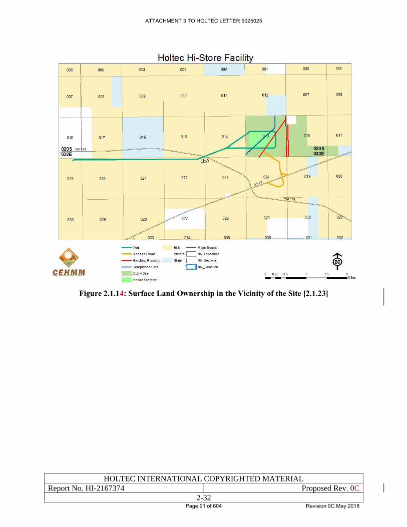
HOLTEC INTERNATIONAL COPYRIGHTED MATERIAL
Report No. HI-2167374 Proposed Rev. 0C
2-32
Figure 2.1.14: Surface Land Ownership in the Vicinity of the Site [2.1.23]
ATTACHMENT 3 TO HOLTEC LETTER 5025025
Page 91 of 604 Revision 0C May 2018
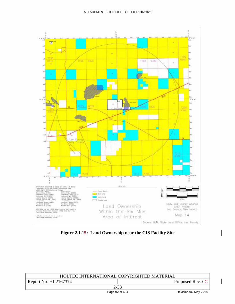
HOLTEC INTERNATIONAL COPYRIGHTED MATERIAL
Report No. HI-2167374 Proposed Rev. 0C
2-33
Figure 2.1.15: Land Ownership near the CIS Facility Site
ATTACHMENT 3 TO HOLTEC LETTER 5025025
Page 92 of 604 Revision 0C May 2018
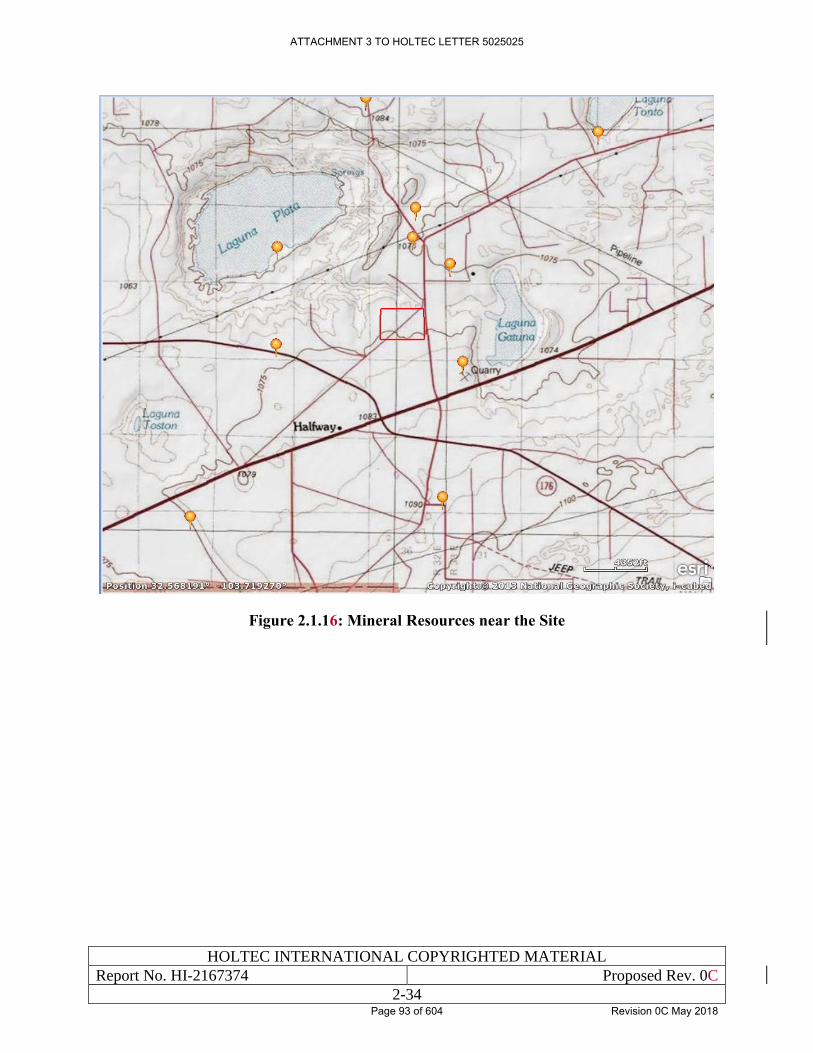
HOLTEC INTERNATIONAL COPYRIGHTED MATERIAL
Report No. HI-2167374 Proposed Rev. 0C
2-34
Figure 2.1.16: Mineral Resources near the Site
ATTACHMENT 3 TO HOLTEC LETTER 5025025
Page 93 of 604 Revision 0C May 2018
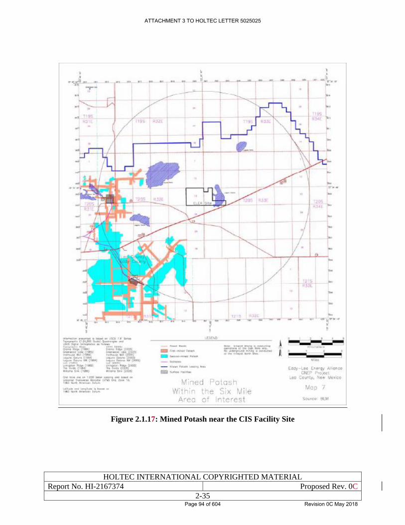
HOLTEC INTERNATIONAL COPYRIGHTED MATERIAL
Report No. HI-2167374 Proposed Rev. 0C
2-35
Figure 2.1.17: Mined Potash near the CIS Facility Site
ATTACHMENT 3 TO HOLTEC LETTER 5025025
Page 94 of 604 Revision 0C May 2018
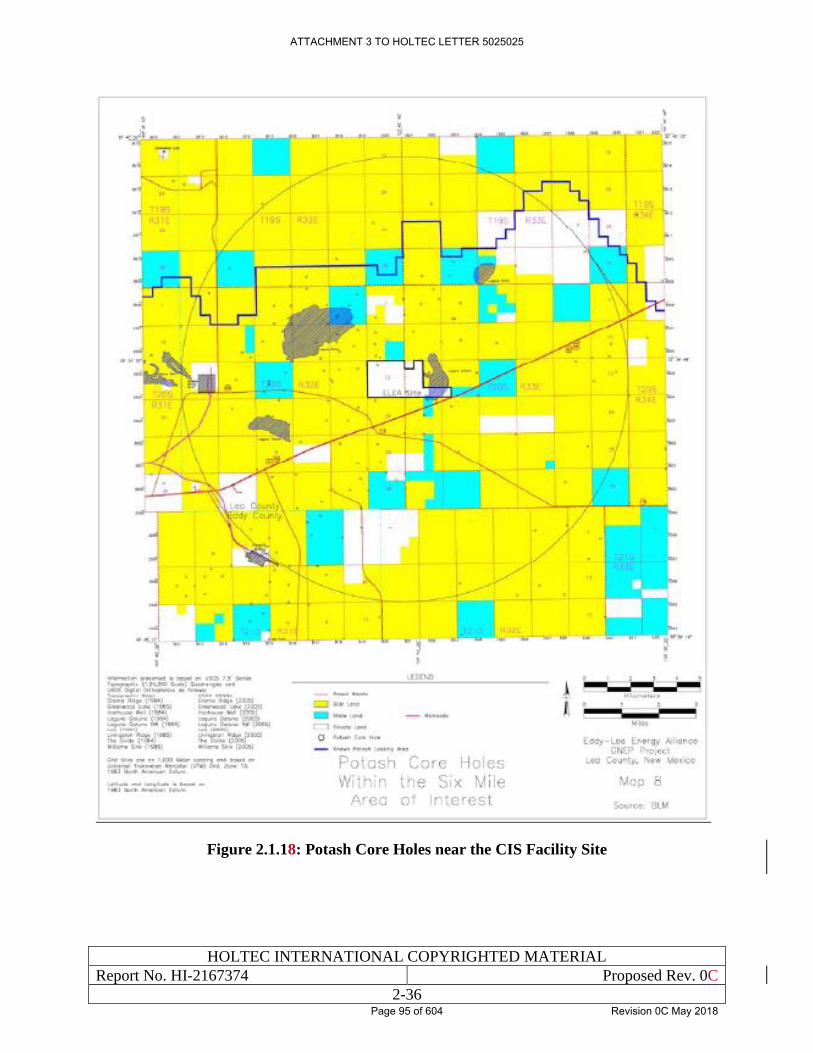
HOLTEC INTERNATIONAL COPYRIGHTED MATERIAL
Report No. HI-2167374 Proposed Rev. 0C
2-36
Figure 2.1.18: Potash Core Holes near the CIS Facility Site
ATTACHMENT 3 TO HOLTEC LETTER 5025025
Page 95 of 604 Revision 0C May 2018
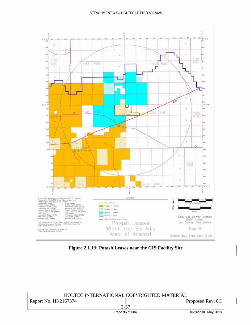
HOLTEC INTERNATIONAL COPYRIGHTED MATERIAL
Report No. HI-2167374 Proposed Rev. 0C
2-37
Figure 2.1.19: Potash Leases near the CIS Facility Site
ATTACHMENT 3 TO HOLTEC LETTER 5025025
Page 96 of 604 Revision 0C May 2018
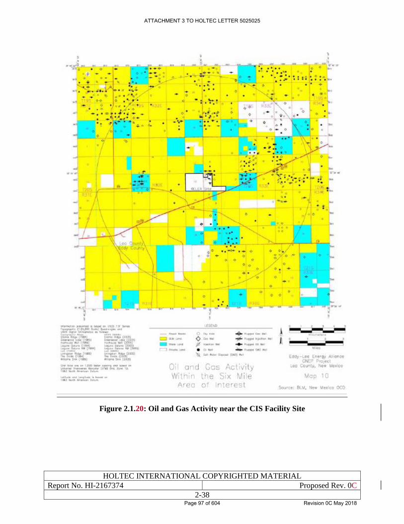
HOLTEC INTERNATIONAL COPYRIGHTED MATERIAL
Report No. HI-2167374 Proposed Rev. 0C
2-38
Figure 2.1.20: Oil and Gas Activity near the CIS Facility Site
ATTACHMENT 3 TO HOLTEC LETTER 5025025
Page 97 of 604 Revision 0C May 2018
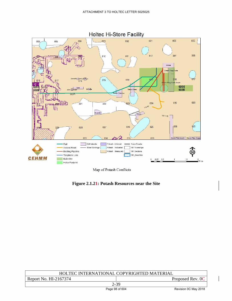
HOLTEC INTERNATIONAL COPYRIGHTED MATERIAL
Report No. HI-2167374 Proposed Rev. 0C
2-39
Figure 2.1.21: Potash Resources near the Site
ATTACHMENT 3 TO HOLTEC LETTER 5025025
Page 98 of 604 Revision 0C May 2018
HOLTEC INTERNATIONAL COPYRIGHTED MATERIAL
Report No. HI-2167374 Proposed Rev. 0C
2-40
2.2 NEARBY INDUSTRIAL, TRANSPORTATION, MILITARY, AND
NUCLEAR FACILITIES
2.2.1 Industrial Facilities
Figure 2.2.1 identifies industrial facilities located within approximately 5 miles of the Site. These
facilities are:
1. Land Farm — oilfield waste management company that remediates contaminated soil from oil
and gas operations. Located 1.9 miles southwest of the Site, contaminated soils are trucked
to the facility and remediated using microbial degradation of the hazardous compounds.
2. Potash Facility — National Potash Mine, located approximately 4.2 miles west of the Site.
This mine first began operations in 1957. Potassium (mainly) is mined below surface with
boring machines and lifted to the surface through shafts using hoists.
3. Transwestern — gas pipeline compressor station located approximately 5.2 miles southwest of
the Site. This station consists of a small building with compressors used to compress natural
gas, transporting it through the gas pipeline.
4. Caliche — mining operation located approximately 4 miles southwest of the Site. Caliche
generally occurs on or near the surface or at depths of 10-20 feet. Caliche is mined using
traditional excavation machinery and is used in construction applications.
None of the facilities located within 5 miles of the Site are engaged in operations that would pose
a hazard to the Site or affect the design basis of the Site.
2.2.2 Pipelines
There are approximately 27,000 miles of energy-related pipelines in New Mexico that are
regulated by the U.S. Department of Transportation’s Pipeline and Hazardous Materials Safety
Administration (PHMSA). Three pipelines are currently near the CIS Facility Site: (1) a
Transwestern (TW) 20-inch diameter natural gas pipeline located approximately 0.8 miles from
the western boundary of the Site, and (2) a DCP Midstream (DCP) 20-inch diameter natural gas
pipeline located approximately 0.16 miles east of the eastern boundary of the Site; and (3) a DCP
10-inch diameter natural gas pipeline located approximately 0.17 miles east of the eastern
boundary of the Site. The two 20-inch pipelines are classified as high-pressure pipelines rated for
a pressure of 1,180 pounds per square inch (psi). They are normally operated at a pressure of
approximately 680 psi. A fourth pipeline is proposed to be constructed near the two DCP pipelines
east of the CIS Facility Site. That pipeline would be a 10.75-inch diameter low-pressure natural
gas pipeline and would run south-to-north between the two existing pipelines which are east of the
CIS Facility [2.2.1].
PHMSA has collected pipeline incident reports since 1970. Although the reporting regulations
and incident report formats have changed several times over the years, PHMSA merged the various
report formats to create pipeline incident trend lines going back 20 years. PHMSA defines
significant incidents based on any of the following conditions:
ATTACHMENT 3 TO HOLTEC LETTER 5025025
Page 99 of 604 Revision 0C May 2018
HOLTEC INTERNATIONAL COPYRIGHTED MATERIAL
Report No. HI-2167374 Proposed Rev. 0C
2-41
• Fatality or injury requiring in-patient hospitalization;
• $50,000 or more in total costs, measured in 1984 dollars; or
• Highly volatile liquid releases of 5 barrels or more or other liquid releases of 50 barrels or
more [2.2.4].
Tables 2.2.1 and 2.2.2 identify significant incidents over the past 20 years involving PHMSA-
regulated pipelines in the U.S. and in New Mexico, respectively.
The most significant incident in New Mexico occurred on August 19, 2000, when a 30-inch
diameter El Paso Natural Gas pipeline ruptured near Carlsbad, New Mexico. That incident killed
12 members of an extended family camping over 600 feet from the rupture point. The force of the
escaping gas created a 51-foot-wide crater about 113 feet along the pipe. A 49-foot section of the
pipe was ejected from the crater, in three pieces measuring approximately 3 feet, 20 feet, and 26
feet in length. The largest piece of pipe was found about 287 feet northwest of the crater. The cause
of the failure was determined to be severe internal corrosion of that pipeline [2.2.3].
In order to determine whether the potential failure of a pipeline could have significant impact on
people or property, the PHMSA has developed a calculation that accounts for the size of the
pipeline and the maximum allowable operating pressure. The term “PIR” means the radius of a
circle within which the potential failure of a pipeline could have significant impact on people or
property. The PIR is determined by the following formula:
𝑟 = 0.69 ∙ √𝑝 ∙ 𝑑2
where:
r = the PIR in feet,
p = the pipeline maximum operating pressure in pounds per square inch (psi), and
d = the nominal pipeline diameter in inches [2.2.2].
Figure 2.2.2 depicts a graphic representation of the results of that formula. As can be seen from
that figure, for the maximum expected diameter pipeline (42-inch) operating at the maximum
pressure (1450 psi), the hazard area radius is not expected to exceed approximately 1,100 feet from
the explosion. For the CIS Facility, there are no pipelines in the vicinity greater than 20-inch
diameter or with operating pressures greater than 1,180 psi. As shown on Figure 2.2.2, for a 24-
inch diameter pipeline with an operating pressure of approximately 1,180 psi, the hazard area
radius is not expected to exceed approximately 600 feet from the explosion. All pipelines near the
CIS Facility are located more than 600 feet from the Site boundary, and more than 1 mile from the
ISFSI.
Table 2.2.3 presents a summary of some of the most relevant pipeline explosions that have
occurred in the U.S. since approximately 1969. As can be seen from that table, impacts occurred
within 1,000 feet of all explosions. Given that there are no pipelines within one-half mile of the
proposed operations at the CIS Facility, it would be extremely unlikely for a pipeline rupture to
impact operations at the facility.
ATTACHMENT 3 TO HOLTEC LETTER 5025025
Page 100 of 604 Revision 0C May 2018
HOLTEC INTERNATIONAL COPYRIGHTED MATERIAL
Report No. HI-2167374 Proposed Rev. 0C
2-42
With regard to past operations at the site involving an oil recovery facility with tanks within the
CIS Facility Site boundary, it should be noted that there are no oil recovery operations presently
occurring on the Site and none are reasonably foreseeable. There are 7 aboveground storage tanks
(ASTs) associated with past brine disposal activities on the site. These ASTs are holding tanks
that were used for storing brine and settling solids and separating residual oil from oil-field brines.
'The tanks range in size from 150 barrels to 250 barrels. These holding tanks or ASTs are not in
use. No containers of hazardous substances have been noted in prior site visits (2007) or most recent
site visits (2016). Within Section 13, which is where the CIS Facility would be located, two additional
tanks (250 gallon barrels) are present at the well location in the southwest portion of the Site.
One active oil/gas well on the southwest portion of Section 13 operates at minimum production to
maintain mineral rights.
2.2.3 Air Transportation
The airspace surrounding the CIS Facility is unrestricted and at any given time there would be the
potential for commercial aircraft, military aircraft, and civilian aircraft to be flying in that airspace
at various altitudes and at various speeds. Commercial aircraft would fly in accordance with flight
plans filed with the Federal Aviation Administration (FAA) and would be controlled by the
national air traffic control system [2.2.5] [2.2.18]. Military aircraft would fly within designated
Military Training Routes (MTRs), which may or may note be flown under air traffic control.
Commercial aircraft flight plans would be limited to the Federal Airways that make up the en route
airspace structure of the National Airspace System. There are multiple federal airways near the
CIS Facility: V83, V102, and V291 [2.2.16] [2.2.17]. Victor routes are low altitude airways that
make up the majority of the lower stratum of the federal en route airspace structure. Victor routes
extend from the floor of the controlled airspace up to but not including 18,000 feet above mean
sea level [2.2.18]. They are defined as straight line segments between VOR stations and have a
width of 4NM on either side of the centerline when VOR stations are less than 102 NM apart, with
the width increasing for VORs farther apart [2.2.18]. Additional information for these airways,
including their distances from the site, is included in Table 2.2.5. These federal airways are
illustrated on Figure 2.2.6.
Because airspace above the United States from the surface to 10,000 feet above sea level is limited
to 250 knots (indicated airspeed) by FAA regulations, any aircraft below 10,000 feet would be
travelling at speeds of less than 250 knots. There is a military exception to this requirement,
however. The Military Training Route Program is a joint venture by the FAA and the Department
of Defense (DOD), developed for use by military aircraft to gain and maintain proficiency in
tactical "low-level" flying. These low-level training routes are generally established below 10,000
feet for speeds in excess of 250 knots. Military Training Routes do not constitute an official
airspace and are all open to civilian traffic [2.2.6].
MTRs are designated either IR (Instrument Route) or VR (Visual Route), with IR routes being
flown under air traffic control [2.2.19]. Military training routes are usually limited to 420 knots,
and in no case are aircraft allowed to exceed Mach 1 within United States sovereign airspace,
except in designated Military Operation Areas. While on the route, military aircraft squawk a
Mode C Transponder code of '4000', which informs controllers that they are 'speeding' on a route.
This squawk however is only legal by military aircraft, while inside a properly scheduled route
corridor [2.2.20].
ATTACHMENT 3 TO HOLTEC LETTER 5025025
Page 101 of 604 Revision 0C May 2018
HOLTEC INTERNATIONAL COPYRIGHTED MATERIAL
Report No. HI-2167374 Proposed Rev. 0C
2-43
There are four designated Military Training Routes in the vicinity of the proposed CIS Facility:
IR-128, IR-180, IR-192, and IR-194. However, these four designations represent only 2 mapped
airways, as IR-128 and IR-180, and IR-192 and IR-194 share the same airway but represent
opposite directions of travel (hereafter referred to as IR-128/180 and IR-192/194, respectively).
IR-128 and IR-192 both represent the North to South direction, while IR-180 and IR-194 represent
the South to North flight direction of their respective corridors [2.2.19] [2.2.16]. The routes are
individually operated by an Air Force Base, which schedule and 'own' the route. IR-128/180 is
“owned” by Dyess AFB while IR-192/194 is “owned” by Holloman AFB. The FAA requires the
military to provide advance notice to other aircraft that the Military Training Routes will be used
to allow for civilian traffic to de-conflict if needed. Department of Defense publication AP/1B
defines all MTRs giving coordinates of airway fixes, or points between segments as well as the
airway width different points along the route. Additional information for these airways, including
their distances from the site and widths, is included in Table 2.2.5. These Military Training Routes
are also illustrated on Figure 2.2.6.
A Military Operation Area (MOA) is “airspace established outside Class A airspace to separate or
segregate certain nonhazardous military activities from IFR Traffic and to identify for VFR traffic
where these activities are conducted." [2.2.21]. The nearest MOAs to the CIS facility are the Talon
High East MOA, which is located north of Carlsbad, NM and the Bronco 3 MOA, which is located
North of Hobbs, NM. The nearest edge of both of these MOAs is greater than 25 miles from the
site.
As discussed below, most of the commercial airline operations at airports in the area of the CIS
Facility involve regional jets. The largest commercial planes (Boeing 737s) are flown in and out
of Midland International Air and Space. A summary of the airplane operations at airports near the
CIS Facility are provided below. Airport operation numbers have been gathered from 2 sources,
first is the Air Traffic Activity Data System (ATADS), which contains the official NAS air traffic
operations data available for public release. The other is GRC Inc.’s AirportIQ 5010, which is a
compilation of FAA form 5010-5 Airport Master Records and Reports. ATADS gives data as far
back as 1990, where AirportIQ gives only the past year’s data. Additionally, ATADS only gives
data for Airports that have an FAA certified Air traffic control tower, so data for some of the
smaller airports has only been sourced from AirportIQ.
Artesia Municipal Airport* is a public use general aviation airport located 4 miles west of the Main
Street business district or Atresia, in Eddy County, New Mexico, approximately 47 miles from the
CIS Facility. The city owned airport and its 2 runways covers 1,440 acres. For the 12 month period
ending April 05, 2017 the airport had approximately 14,050 aircraft operations, an average of 38
per day: 82 percent general aviation, and 18 percent military. During this period, 30 aircraft were
based at this airport: 26 single engine, and 4 multi engine [2.2.22].
*Note that Atresia Municipal Airport does not have an FAA funded air traffic control
tower, and therefore does not have data reported to ATADS.
Cavern City Air Terminal* is a public use airport in Eddy County, New Mexico, United States. It
is owned by the city of Carlsbad and located five nautical miles southwest of its central business
district, approximately 34 miles from the CIS Facility. The airport is served by one commercial
airline. For the 12 month period ending December, 31, 2016, the airport had approximately 6,900
ATTACHMENT 3 TO HOLTEC LETTER 5025025
Page 102 of 604 Revision 0C May 2018
HOLTEC INTERNATIONAL COPYRIGHTED MATERIAL
Report No. HI-2167374 Proposed Rev. 0C
2-44
aircraft operations, an average of 19 per day: 53 percent general aviation, 4 percent air taxi, 39
percent air carrier, and 4 percent military. During this period, 22 aircraft were based at this airport:
15 single-engine, 2 multi-engine, 2 jet, 2 helicopter, and 1 ultra-light [2.2.23]. The approach pattern
for Cavern City Air Terminal is approximately 14 miles North East of the airport, locating it a little
more than 22 miles from the CIS Facility see Table 2.2.6 [2.2.30].
*Note that Cavern City Air Terminal does not have an FAA funded air traffic control tower,
and therefore does not have data reported to ATADS.
Lea County Regional Airport* is 4 miles west of Hobbs in Lea County, NM , approximately 30
miles from the CIS Facility. The airport covers 898 acres and has three runways. It is an FAA
certified commercial airport served by United Airlines' affiliate with daily regional flights. Lea
County Regional Airport is the largest of the three airports owned and operated by Lea County
Government. Lea County also owns and operated two general aviation airports in Lovington and
Jal, New Mexico. For the 12 month period ending April 30, 2017, the Lea County Regional
Airport had approximately 12,745 aircraft operations, an average of 35 per day: 67 percent general
aviation, 16 percent air taxi, 10 percent air carrier, and 7 percent military. During this period, 52
aircraft were based at this airport: 41 single-engine, 6 multi-engine, 4 jet, and 1 helicopter [2.2.24].
Average annual aircraft operations for the past 15 years is approximately 12,500, this data is
illustrated in Table 2.2.7 [2.2.28]. The missed approach holding pattern for Lea County Regional
is approximately 19 miles South West of the airport, locating it just over 12.5 miles from the CIS
Facility see Table 2.2.6 [2.2.31]
*Note that for Lea County Regional data reported on AiportIQ does not match the data for
the same time period reported on ATADS.
Lea County - Zip Franklin Memorial Airport* also known as Lovington airport is located 3 miles west of the central business district of Lovington in Lea county, NM, approximately 32 miles from the CIS
Facility. For the 12-month period ending April 3, 2017 the airport had approximately 2,200 aircraft operations, all general aviation. During this period, 12 aircraft were based at this airport: 11 single engine, and 1 multi engine [2.2.25].
*Note that Zip Franklin Memorial Airport does not have an FAA funded air traffic control
tower, and therefore does not have data reported to ATADS.
Midland International Air and Space is located approximately midway between the Texas cities of
Midland and Odessa. It is owned and operated by the City of Midland. In September 2014 it
became the first US facility licensed by the FAA to serve both scheduled airline flights and
commercial human spaceflight. Midland International Air and Space Port is ranked eighth in
Texas for primary commercial service airports. For the 12-month period ending April 30, 2017,
the airport has approximately 63,000 aircraft operations, averaging 173 per day: 43 percent general
aviation, 14 percent air taxi, 18 percent air carrier, and 25 percent military. During this period, 105
aircraft were based at the airport: 24 single-engine, 40 multi-engine, 39 jet and 2 helicopter. The
airport has three airlines, two serving hubs with regional jets and one (Southwest) flying mainline
jets (Boeing 737s) [2.2.26]. Average annual aircraft operations for the past 15 years is
approximately 76,412, this data is presented in Table 2.2.8 [2.2.28].
Roswell International Air Center is located 5 miles south of the central business district of Roswell,
ATTACHMENT 3 TO HOLTEC LETTER 5025025
Page 103 of 604 Revision 0C May 2018
HOLTEC INTERNATIONAL COPYRIGHTED MATERIAL
Report No. HI-2167374 Proposed Rev. 0C
2-45
in Chaves County, NM, approximately 68 miles from the CIS Facility. The former Air Force Base
currently covers 5,029 acres and has 2 runways. It is also an FAA certified commercial airport but
is served by American Airlines with daily regional flights to Dallas-Fort Worth and Phoenix. The
airport is owned by the city of Roswell and also serves as a storage facility for retired aircraft. For
the 12-month period ending December 31, 2016, the Roswell International Air Center had
approximately 34,280 aircraft operations, an average of 94 per day: 23 percent general aviation,
18 percent air taxi, 1 percent air carrier, and 58 percent military. During this period, 39 aircraft
were based there: 31 single engine, 4 multi engine, 3 jet, and 1 helicopter [2.2.27]. Average annual
aircraft operations for the past 15 years is approximately 49,050, this data illustrated in Table 2.2.9
[2.2.28].
In order to assure that risks from aircraft hazards is sufficiently low, a probabilistic assessment of
the nearby air transportation infrastructure as described above has been performed. NUREG-
0800 Standard Review Plan, gives acceptance criteria for the probabilistic assessment to meet
NRC regulations. NUREG-0800 section 3.5.1.6 states that the requirements are met if the
probability of aircraft accident is less than an order of magnitude of 10-7 per year. It also provides
screening criteria which, if met, the probability is considered to be less than the 10-7 threshold by
inspection.
Table 2.2.4 summarizes the data presented for each of the nearby airports, including its distance
from the site, annual number of operations, as well as the SRP screening criteria. The value used
for annual aircraft operations is the higher of the 15-year average from ATADS or the most recent
year’s value from AirportIQ (where both values are available). Given the distance to each of the
nearby airports, none of their annual operations comes within an order of magnitude of the
screening criteria. Therefore, each of the nearby airports pose a negligible hazard risk.
Table 2.2.5and Table 2.2.6 summarizes the data presented for each of the federal airways, and
holding or approach patterns that are near the site. The tables include distance from the site to the
nearest edge of the airway or holding/approach pattern, as well as the screening criteria. Each of
the proximate federal airways, holding patterns and approach patterns are greater than the 2-statute
mile SRP screening criteria. Therefore, they pose a negligible hazard risk.
Table 2.2.5 also summarizes the data presented for each of the adjacent Military Training Routes,
including the distance from the site to the nearest edge of the route, as well as the SRP screening
criteria. The nearest edge of IR-192/194 is greater than 10 miles from the site, which is greater
than the screening criteria of 5 statute miles. However, the centerline of IR-128/180 is less than 2
miles from the site, which puts its full width over top of the CIS Facility. Therefore, IR-192/194
is screened by inspection, while IR-128/180 needs to be assessed following SRP Section 3.5.1.6
III [2.2.33].
SRP Section 3.5.1.6 III provides the following equation for determining the probability of an
aircraft using an airway crashing at the site:
𝑃 = 𝐶 ∗ 𝑁 ∗ 𝐴 𝑤⁄
Where:
C = in-flight Crash Rate per mile for aircraft using the airway
ATTACHMENT 3 TO HOLTEC LETTER 5025025
Page 104 of 604 Revision 0C May 2018
HOLTEC INTERNATIONAL COPYRIGHTED MATERIAL
Report No. HI-2167374 Proposed Rev. 0C
2-46
N = Number of flights per year along the airway
A = effective Area of the site in square miles
w = Width of the airway in miles
The area of each of the important to safety structures constitutes the effective area of the site. In
this case, it is conservatively taken as the out to out area of the full 10,000 cask UMAX ISFSI
array plus the area of the Cask Transfer Building, A = 0.173 mi2. The total width of the airway, as
noted in Table 2.2.5, is 7 miles. And using a crash rate of C = 4*10-9 (an order of magnitude greater
than commercial aircraft), the number of flights per year that would yield a crash probability higher
than P = 10-7 would be 1011 flights.
The Air Force Base that controls IR-128/180, Dyess AFB has stated that “IR-180 has not been
used in years and we do not expect to fly IR-180 in the near future, the way it's currently laid out”
[2.2.32]. They also provided Figure 2.2.7 showing how IR-128 is flown and how they “expect to
fly it in the foreseeable future” [2.2.32]. Figure 2.2.7 illustrates the racetrack which is used as part
of operations on IR-128 and then exited from. This racetrack is north of Lovington, NM greater
than 30 miles from the site. The portion of IR-128 closest to the site is not used. Therefore, it is
reasonable to assume that less than 1011 flights per year occur on these MTRs near the site, and
they pose a negligible hazard risk.
2.2.4 Ground Transportation
U.S. Highway 62/180, approximately 1 mile south of the proposed CIS Facility is the closest and
most trafficked public road. It provides a route from the state of Texas to Carlsbad, New Mexico
and points further west. It is a divided highway with a maximum speed limit of 70 miles per hour
in the area near the proposed CIS Facility. This, in addition to other transportation infrastructure
near the site, can be seen in Figure 2.2.4. This highway is on the National Hazardous Materials
Route Registry (79 FR 40844, July 14, 2014) and can be used for the transportation of radioactive
waste materials to WIPP [2.2.7] (Note: as shown on Figure 2.2.5, the WIPP route is approximately
5 miles southwest of the CIS Facility. There have been instances where transuranic wastes
associated with WIPP have been transported along U.S. Highway 62/180 within approximately 1
mile of the proposed CIS Facility).
Like similar roads, commercial shipments of hazardous materials are also transported over U.S.
Highway 62/180. Such shipments could include a wide range of hazardous materials, including,
but not limited to: gasoline, diesel fuel, acids, carbon dioxide (CO2), nitrogen (N2), liquid nitrogen
(LN2), chlorine (Cl) gas, refrigerants, fuel gases, oxygen (O2), explosives, and low-level
radioactive materials. The State of New Mexico does not keep records of hazardous material
shipments via roadways or rail. Consequently, specific types and quantities cannot be provided.
In 2015, the annual average daily traffic on U.S. Highway 62/180 was 5,696 vehicles per day in
the vicinity of the proposed Site (near the Eddy-Lea County line) and approximately 43 percent of
these vehicles were associated with commercial trucks [2.2.9]. In 2014, in the entire state of New
Mexico, there were 69 Hazardous Material Incidents required to be reported by 49 CFR §§ 171.15
and 171.16 [2.2.8]. While truck shipments in the area are expected to rise over time, this highway
ATTACHMENT 3 TO HOLTEC LETTER 5025025
Page 105 of 604 Revision 0C May 2018
HOLTEC INTERNATIONAL COPYRIGHTED MATERIAL
Report No. HI-2167374 Proposed Rev. 0C
2-47
is not included in the planning for increasing freight traffic in the “New Mexico Freight Plan”
[2.2.10].
The nearest operating railroad is an industrial railroad approximately 3.8 miles west of the
proposed CIS Facility and serves the local potash mines to transport ore to the refiners. The potash
ore is not a hazardous material. From 2008 to 2012, the annual average of train accidents per 1,000
railroad miles was 10.4, the fatality rate was zero and the injury rate was 0.4 [2.2.10]. As with
highway transport, shipments by rail could include a wide range of hazardous materials, including,
but not limited to: gasoline, diesel fuel, acids, CO2, N2. LN2, Cl gas, refrigerants, fuel gases, O2,
explosives. However, no specific records are maintained by the state of New Mexico regarding
hazardous material shipments via rail. All transportation infrastructure can be seen in Figure 2.2.5.
2.2.5 Nuclear Facilities
With regard to nuclear facilities, Figure 2.2.5 depicts existing or planned nuclear facilities in the
vicinity of the Site. As shown on that Figure, all of these facilities would be within 50-miles of the
proposed Site. A brief description of these other nuclear facilities follows:
1. Waste Isolation Pilot Plant (WIPP): Located approximately 16 miles southwest of the
proposed Site, WIPP is the nation’s first underground repository permitted to safely and
permanently dispose of transuranic (TRU) radioactive and mixed waste generated through
defense activities and programs. WIPP, which has been operational since March 1999,
stores TRU in underground salt caverns approximately 2,150 feet deep. From the first
receipt of waste in March 1999 through the end of 2014, approximately 90,983 cubic
meters of TRU waste has been disposed of at the WIPP facility. The environmental impacts
of the WIPP are described in the Waste Isolation Pilot Plant Disposal Phase Final
Supplemental Environmental Impact Statement (DOE/EIS-0026-S2) [2.2.11], as well as
the Waste Isolation Pilot Plant Annual Site Environmental Report for 2014 [2.2.12].
2. National Enrichment Facility (NEF): Located approximately 38 miles southeast of the
proposed Site, the NEF is used to enrich uranium for use in manufacturing nuclear fuel for
commercial nuclear power reactors. NEF enriches uranium using a gas centrifuge process.
The environmental impacts of the NEF are documented in NUREG-1790 [2.2.13].
3. Fluorine Extraction Process & Depleted Uranium De-conversion Plan (FEP/DUP):
Located approximately 23 miles northeast of the proposed Site, the FEP/DUP will de-
convert depleted uranium hexafluoride (DUF6) into fluoride products for commercial
resale and uranium oxides for disposal. Construction of that facility is expected to begin
before the end of 2016. The environmental impacts of the FEP/DUP are documented in
NUREG-2113 [2.214].
4. Waste Control Specialists (WCS) CIS Facility: In May 2016, WCS submitted a license
application to the NRC to construct and operate a CIS Facility in Andrews County, Texas,
approximately 39 miles east of the Holtec proposed Site. The WCS CIS Facility would be
similar to the Holtec Site, but would utilize AREVA’s horizontal canister storage system
(NUHOMS) at the facility. A limited number of vertical canisters supplied by NAC may
also be stored. The environmental impacts of the WCS CIS Facility are documented in an
ER which WCS submitted to the NRC in May 2016 [2.2.15]. In addition, the NRC is
expected to prepare an EIS for the WCS CIS Facility.
ATTACHMENT 3 TO HOLTEC LETTER 5025025
Page 106 of 604 Revision 0C May 2018
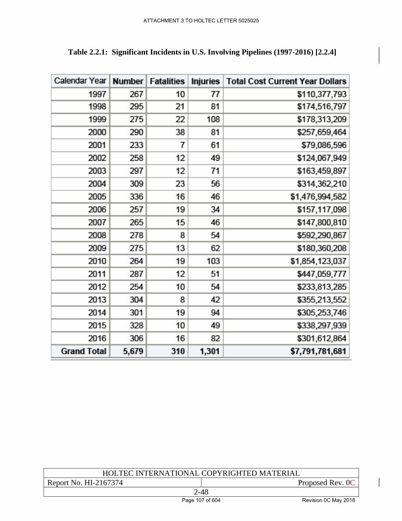
HOLTEC INTERNATIONAL COPYRIGHTED MATERIAL
Report No. HI-2167374 Proposed Rev. 0C
2-48
Table 2.2.1: Significant Incidents in U.S. Involving Pipelines (1997-2016) [2.2.4]
ATTACHMENT 3 TO HOLTEC LETTER 5025025
Page 107 of 604 Revision 0C May 2018
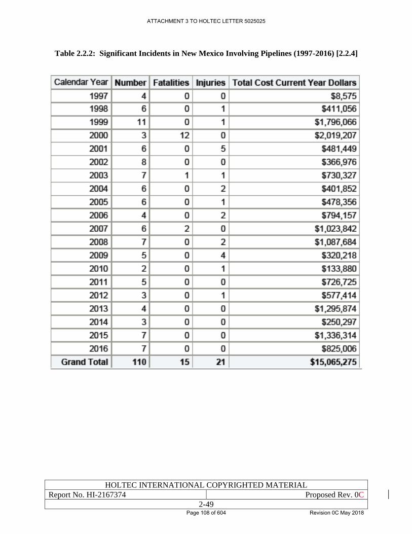
HOLTEC INTERNATIONAL COPYRIGHTED MATERIAL
Report No. HI-2167374 Proposed Rev. 0C
2-49
Table 2.2.2: Significant Incidents in New Mexico Involving Pipelines (1997-2016) [2.2.4]
ATTACHMENT 3 TO HOLTEC LETTER 5025025
Page 108 of 604 Revision 0C May 2018
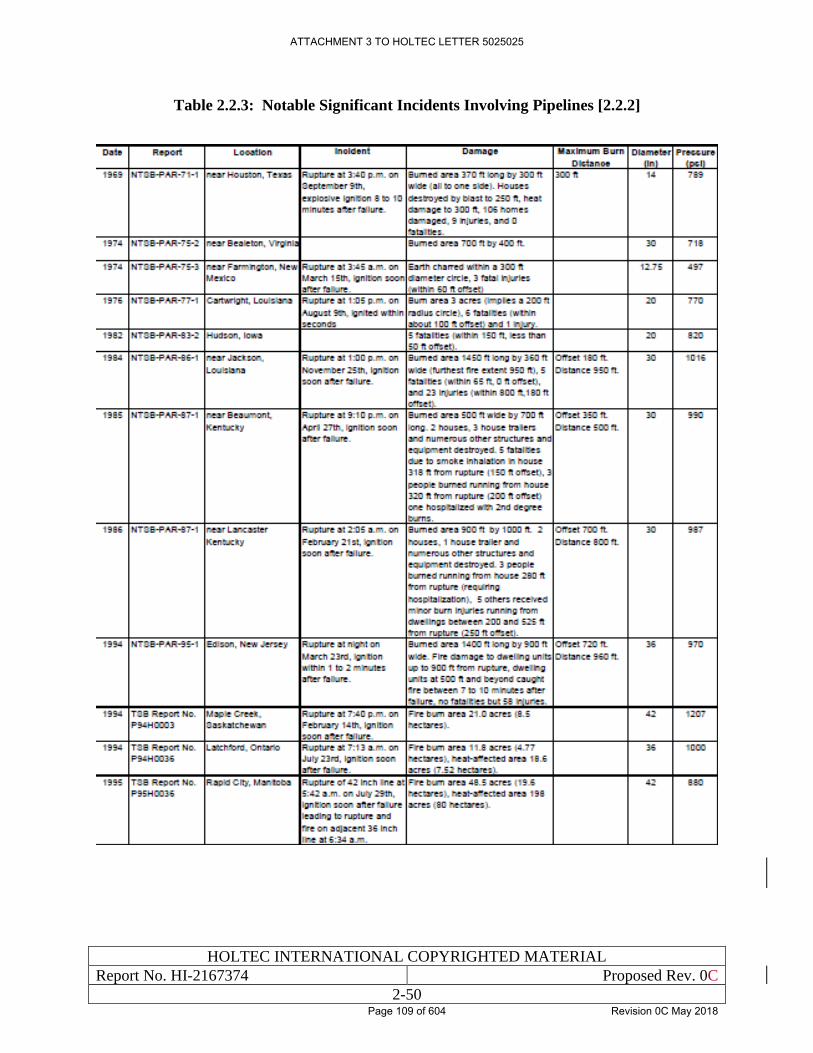
HOLTEC INTERNATIONAL COPYRIGHTED MATERIAL
Report No. HI-2167374 Proposed Rev. 0C
2-50
Table 2.2.3: Notable Significant Incidents Involving Pipelines [2.2.2]
ATTACHMENT 3 TO HOLTEC LETTER 5025025
Page 109 of 604 Revision 0C May 2018
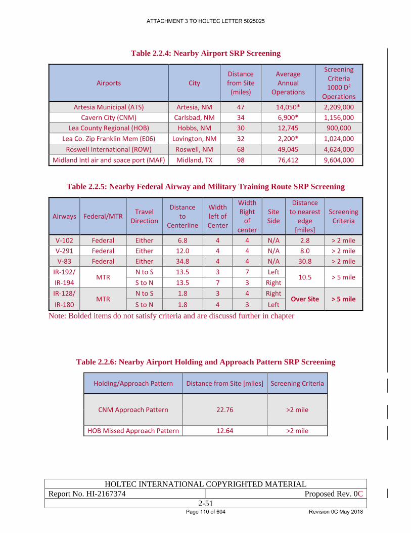
HOLTEC INTERNATIONAL COPYRIGHTED MATERIAL
Report No. HI-2167374 Proposed Rev. 0C
2-51
Table 2.2.4: Nearby Airport SRP Screening
Airports City Distance from Site
(miles)
Average Annual
Operations
Screening Criteria 1000 D2
Operations
Artesia Municipal (ATS) Artesia, NM 47 14,050* 2,209,000
Cavern City (CNM) Carlsbad, NM 34 6,900* 1,156,000
Lea County Regional (HOB) Hobbs, NM 30 12,745 900,000
Lea Co. Zip Franklin Mem (E06) Lovington, NM 32 2,200* 1,024,000
Roswell International (ROW) Roswell, NM 68 49,045 4,624,000
Midland Intl air and space port (MAF) Midland, TX 98 76,412 9,604,000
Table 2.2.5: Nearby Federal Airway and Military Training Route SRP Screening
Airways Federal/MTR Travel
Direction
Distance to
Centerline
Width left of Center
Width Right
of center
Site Side
Distance to nearest
edge [miles]
Screening Criteria
V-102 Federal Either 6.8 4 4 N/A 2.8 > 2 mile
V-291 Federal Either 12.0 4 4 N/A 8.0 > 2 mile
V-83 Federal Either 34.8 4 4 N/A 30.8 > 2 mile
IR-192/ MTR
N to S 13.5 3 7 Left 10.5 > 5 mile
IR-194 S to N 13.5 7 3 Right
IR-128/ MTR
N to S 1.8 3 4 Right Over Site > 5 mile
IR-180 S to N 1.8 4 3 Left
Note: Bolded items do not satisfy criteria and are discussd further in chapter
Table 2.2.6: Nearby Airport Holding and Approach Pattern SRP Screening
Holding/Approach Pattern Distance from Site [miles] Screening Criteria
CNM Approach Pattern 22.76 >2 mile
HOB Missed Approach Pattern 12.64 >2 mile
ATTACHMENT 3 TO HOLTEC LETTER 5025025
Page 110 of 604 Revision 0C May 2018
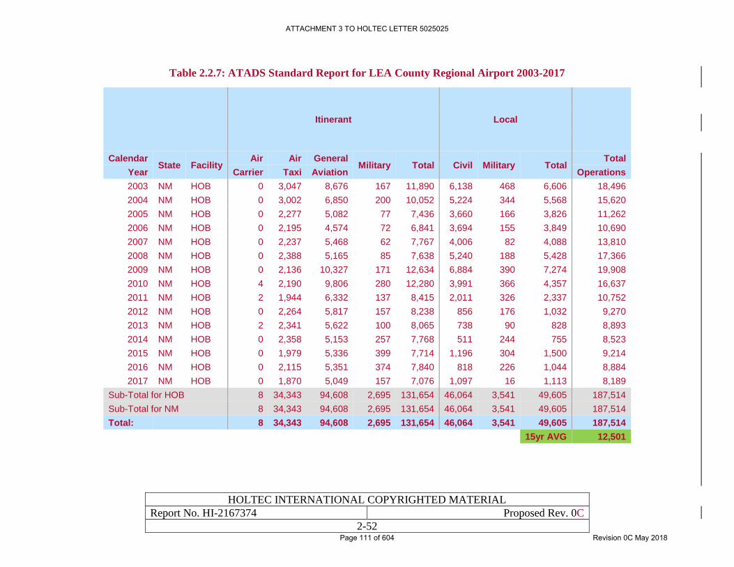
HOLTEC INTERNATIONAL COPYRIGHTED MATERIAL
Report No. HI-2167374 Proposed Rev. 0C
2-52
Table 2.2.7: ATADS Standard Report for LEA County Regional Airport 2003-2017
Itinerant Local
Calendar State Facility
Air Air General Military Total Civil Military Total
Total
Year Carrier Taxi Aviation Operations
2003 NM HOB 0 3,047 8,676 167 11,890 6,138 468 6,606 18,496
2004 NM HOB 0 3,002 6,850 200 10,052 5,224 344 5,568 15,620
2005 NM HOB 0 2,277 5,082 77 7,436 3,660 166 3,826 11,262
2006 NM HOB 0 2,195 4,574 72 6,841 3,694 155 3,849 10,690
2007 NM HOB 0 2,237 5,468 62 7,767 4,006 82 4,088 13,810
2008 NM HOB 0 2,388 5,165 85 7,638 5,240 188 5,428 17,366
2009 NM HOB 0 2,136 10,327 171 12,634 6,884 390 7,274 19,908
2010 NM HOB 4 2,190 9,806 280 12,280 3,991 366 4,357 16,637
2011 NM HOB 2 1,944 6,332 137 8,415 2,011 326 2,337 10,752
2012 NM HOB 0 2,264 5,817 157 8,238 856 176 1,032 9,270
2013 NM HOB 2 2,341 5,622 100 8,065 738 90 828 8,893
2014 NM HOB 0 2,358 5,153 257 7,768 511 244 755 8,523
2015 NM HOB 0 1,979 5,336 399 7,714 1,196 304 1,500 9,214
2016 NM HOB 0 2,115 5,351 374 7,840 818 226 1,044 8,884
2017 NM HOB 0 1,870 5,049 157 7,076 1,097 16 1,113 8,189
Sub-Total for HOB 8 34,343 94,608 2,695 131,654 46,064 3,541 49,605 187,514
Sub-Total for NM 8 34,343 94,608 2,695 131,654 46,064 3,541 49,605 187,514
Total: 8 34,343 94,608 2,695 131,654 46,064 3,541 49,605 187,514
15yr AVG 12,501
ATTACHMENT 3 TO HOLTEC LETTER 5025025
Page 111 of 604 Revision 0C May 2018
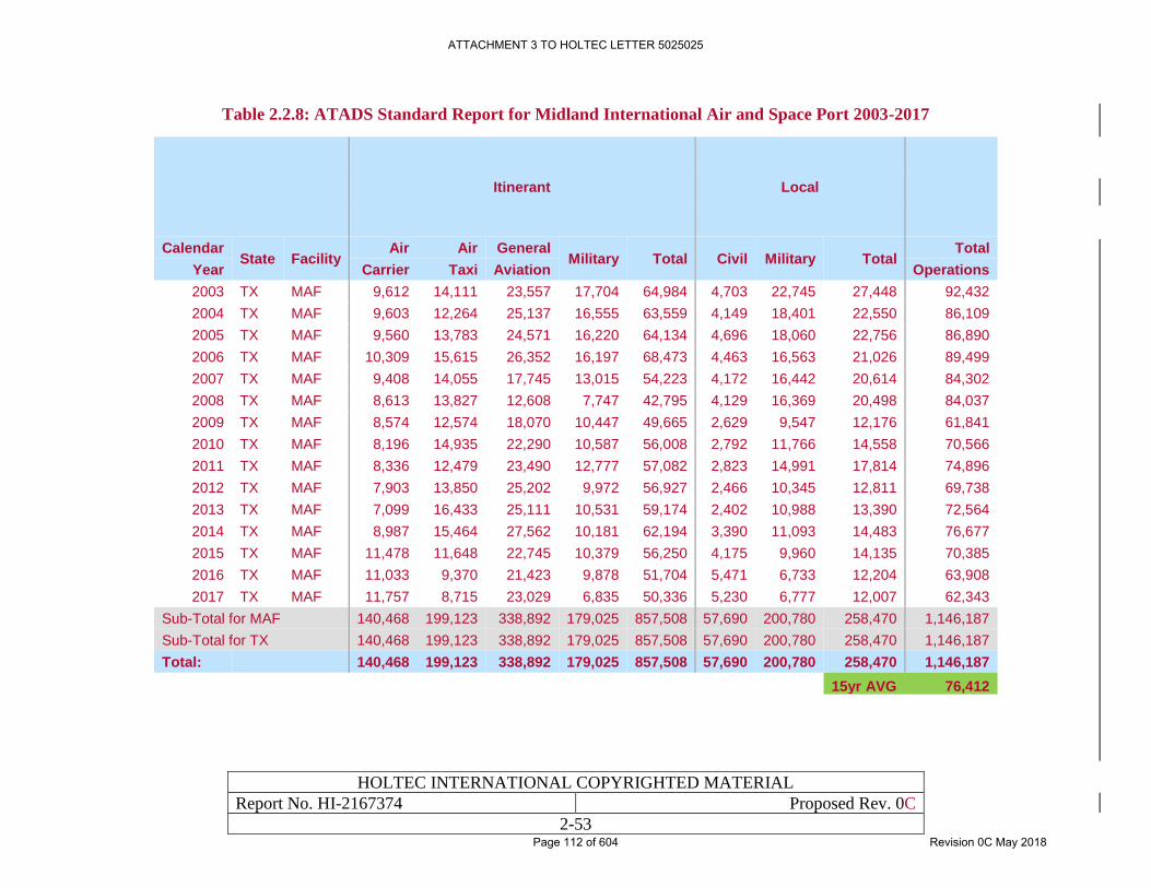
HOLTEC INTERNATIONAL COPYRIGHTED MATERIAL
Report No. HI-2167374 Proposed Rev. 0C
2-53
Table 2.2.8: ATADS Standard Report for Midland International Air and Space Port 2003-2017
Itinerant Local
Calendar State Facility
Air Air General Military Total Civil Military Total
Total
Year Carrier Taxi Aviation Operations
2003 TX MAF 9,612 14,111 23,557 17,704 64,984 4,703 22,745 27,448 92,432
2004 TX MAF 9,603 12,264 25,137 16,555 63,559 4,149 18,401 22,550 86,109
2005 TX MAF 9,560 13,783 24,571 16,220 64,134 4,696 18,060 22,756 86,890
2006 TX MAF 10,309 15,615 26,352 16,197 68,473 4,463 16,563 21,026 89,499
2007 TX MAF 9,408 14,055 17,745 13,015 54,223 4,172 16,442 20,614 84,302
2008 TX MAF 8,613 13,827 12,608 7,747 42,795 4,129 16,369 20,498 84,037
2009 TX MAF 8,574 12,574 18,070 10,447 49,665 2,629 9,547 12,176 61,841
2010 TX MAF 8,196 14,935 22,290 10,587 56,008 2,792 11,766 14,558 70,566
2011 TX MAF 8,336 12,479 23,490 12,777 57,082 2,823 14,991 17,814 74,896
2012 TX MAF 7,903 13,850 25,202 9,972 56,927 2,466 10,345 12,811 69,738
2013 TX MAF 7,099 16,433 25,111 10,531 59,174 2,402 10,988 13,390 72,564
2014 TX MAF 8,987 15,464 27,562 10,181 62,194 3,390 11,093 14,483 76,677
2015 TX MAF 11,478 11,648 22,745 10,379 56,250 4,175 9,960 14,135 70,385
2016 TX MAF 11,033 9,370 21,423 9,878 51,704 5,471 6,733 12,204 63,908
2017 TX MAF 11,757 8,715 23,029 6,835 50,336 5,230 6,777 12,007 62,343
Sub-Total for MAF 140,468 199,123 338,892 179,025 857,508 57,690 200,780 258,470 1,146,187
Sub-Total for TX 140,468 199,123 338,892 179,025 857,508 57,690 200,780 258,470 1,146,187
Total: 140,468 199,123 338,892 179,025 857,508 57,690 200,780 258,470 1,146,187
15yr AVG 76,412
ATTACHMENT 3 TO HOLTEC LETTER 5025025
Page 112 of 604 Revision 0C May 2018
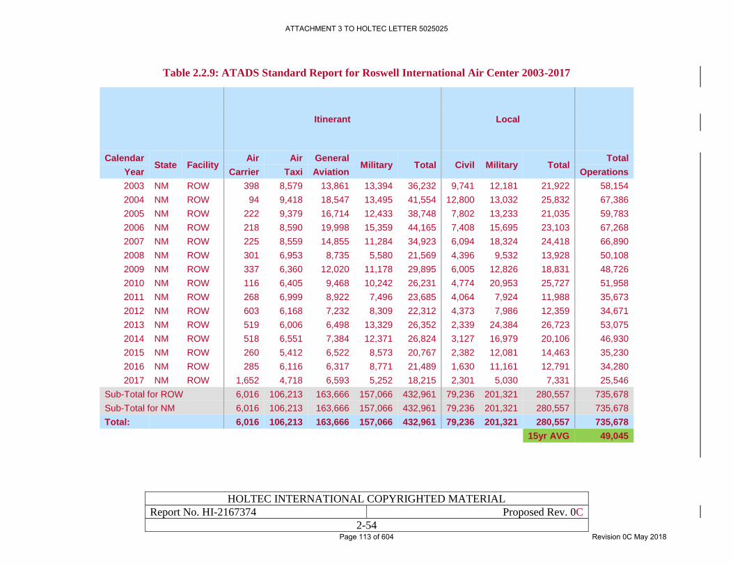
HOLTEC INTERNATIONAL COPYRIGHTED MATERIAL
Report No. HI-2167374 Proposed Rev. 0C
2-54
Table 2.2.9: ATADS Standard Report for Roswell International Air Center 2003-2017
Itinerant Local
Calendar State Facility
Air Air General Military Total Civil Military Total
Total
Year Carrier Taxi Aviation Operations
2003 NM ROW 398 8,579 13,861 13,394 36,232 9,741 12,181 21,922 58,154
2004 NM ROW 94 9,418 18,547 13,495 41,554 12,800 13,032 25,832 67,386
2005 NM ROW 222 9,379 16,714 12,433 38,748 7,802 13,233 21,035 59,783
2006 NM ROW 218 8,590 19,998 15,359 44,165 7,408 15,695 23,103 67,268
2007 NM ROW 225 8,559 14,855 11,284 34,923 6,094 18,324 24,418 66,890
2008 NM ROW 301 6,953 8,735 5,580 21,569 4,396 9,532 13,928 50,108
2009 NM ROW 337 6,360 12,020 11,178 29,895 6,005 12,826 18,831 48,726
2010 NM ROW 116 6,405 9,468 10,242 26,231 4,774 20,953 25,727 51,958
2011 NM ROW 268 6,999 8,922 7,496 23,685 4,064 7,924 11,988 35,673
2012 NM ROW 603 6,168 7,232 8,309 22,312 4,373 7,986 12,359 34,671
2013 NM ROW 519 6,006 6,498 13,329 26,352 2,339 24,384 26,723 53,075
2014 NM ROW 518 6,551 7,384 12,371 26,824 3,127 16,979 20,106 46,930
2015 NM ROW 260 5,412 6,522 8,573 20,767 2,382 12,081 14,463 35,230
2016 NM ROW 285 6,116 6,317 8,771 21,489 1,630 11,161 12,791 34,280
2017 NM ROW 1,652 4,718 6,593 5,252 18,215 2,301 5,030 7,331 25,546
Sub-Total for ROW 6,016 106,213 163,666 157,066 432,961 79,236 201,321 280,557 735,678
Sub-Total for NM 6,016 106,213 163,666 157,066 432,961 79,236 201,321 280,557 735,678
Total: 6,016 106,213 163,666 157,066 432,961 79,236 201,321 280,557 735,678
15yr AVG 49,045
ATTACHMENT 3 TO HOLTEC LETTER 5025025
Page 113 of 604 Revision 0C May 2018
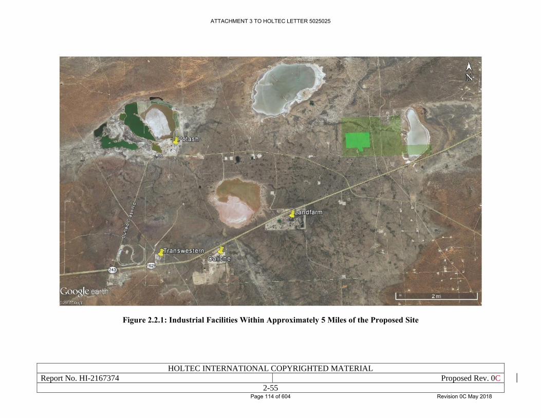
HOLTEC INTERNATIONAL COPYRIGHTED MATERIAL
Report No. HI-2167374 Proposed Rev. 0C
2-55
Figure 2.2.1: Industrial Facilities Within Approximately 5 Miles of the Proposed Site
ATTACHMENT 3 TO HOLTEC LETTER 5025025
Page 114 of 604 Revision 0C May 2018
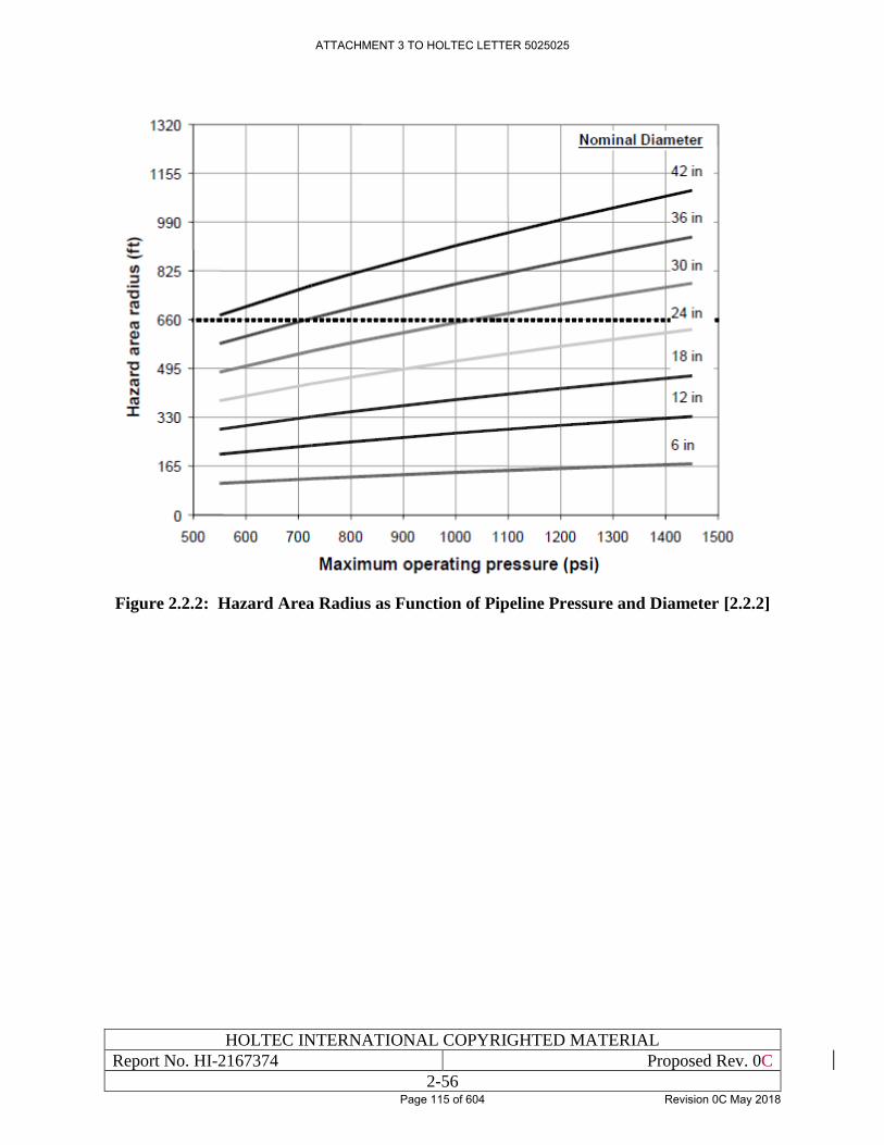
HOLTEC INTERNATIONAL COPYRIGHTED MATERIAL
Report No. HI-2167374 Proposed Rev. 0C
2-56
Figure 2.2.2: Hazard Area Radius as Function of Pipeline Pressure and Diameter [2.2.2]
ATTACHMENT 3 TO HOLTEC LETTER 5025025
Page 115 of 604 Revision 0C May 2018
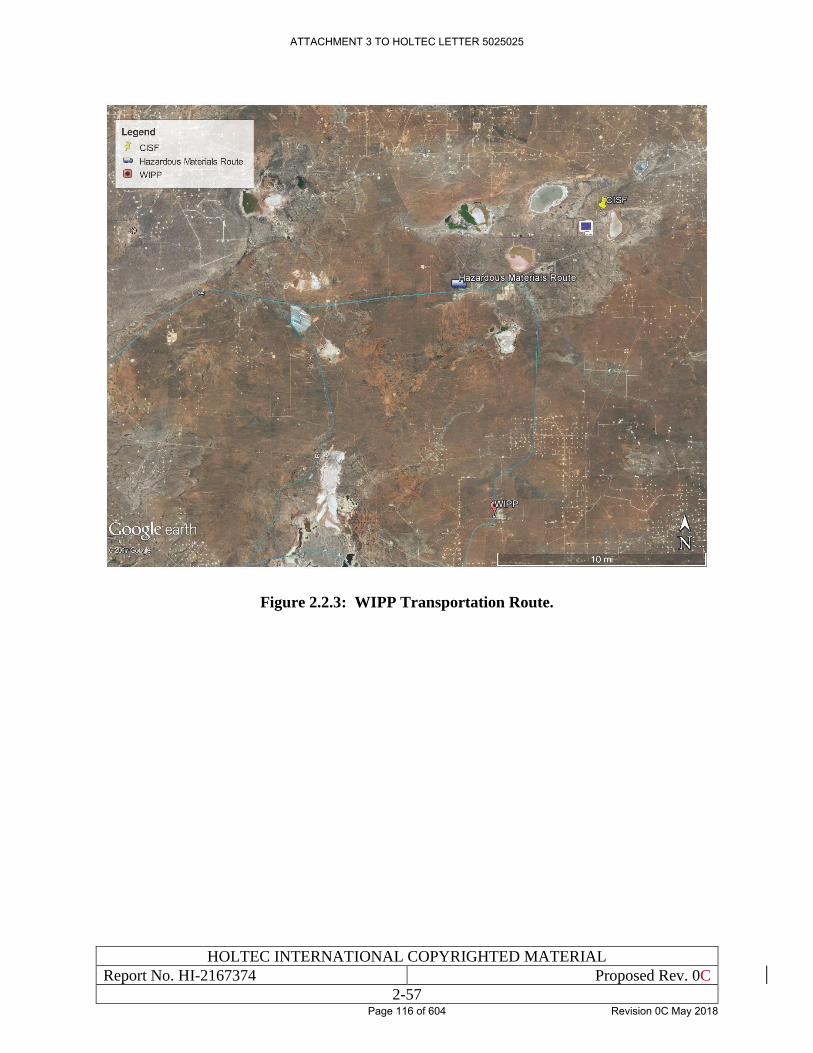
HOLTEC INTERNATIONAL COPYRIGHTED MATERIAL
Report No. HI-2167374 Proposed Rev. 0C
2-57
Figure 2.2.3: WIPP Transportation Route.
ATTACHMENT 3 TO HOLTEC LETTER 5025025
Page 116 of 604 Revision 0C May 2018
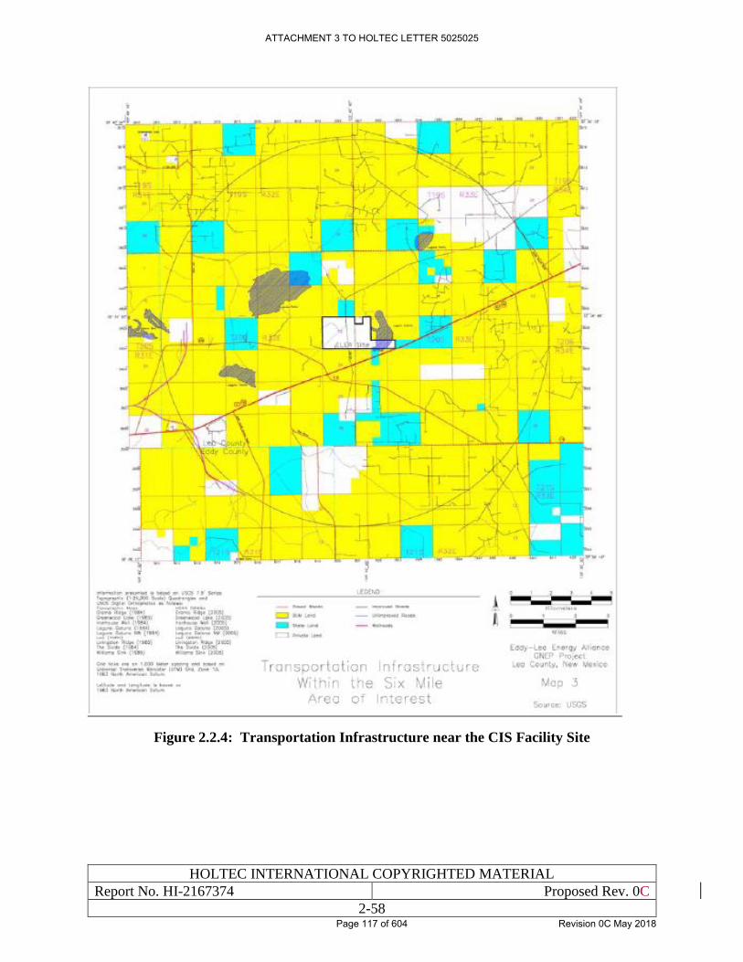
HOLTEC INTERNATIONAL COPYRIGHTED MATERIAL
Report No. HI-2167374 Proposed Rev. 0C
2-58
Figure 2.2.4: Transportation Infrastructure near the CIS Facility Site
ATTACHMENT 3 TO HOLTEC LETTER 5025025
Page 117 of 604 Revision 0C May 2018
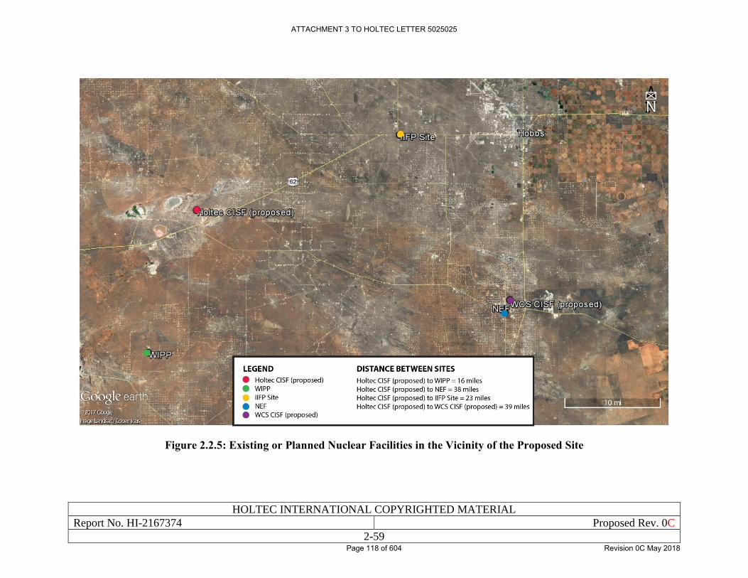
HOLTEC INTERNATIONAL COPYRIGHTED MATERIAL
Report No. HI-2167374 Proposed Rev. 0C
2-59
Figure 2.2.5: Existing or Planned Nuclear Facilities in the Vicinity of the Proposed Site
ATTACHMENT 3 TO HOLTEC LETTER 5025025
Page 118 of 604 Revision 0C May 2018
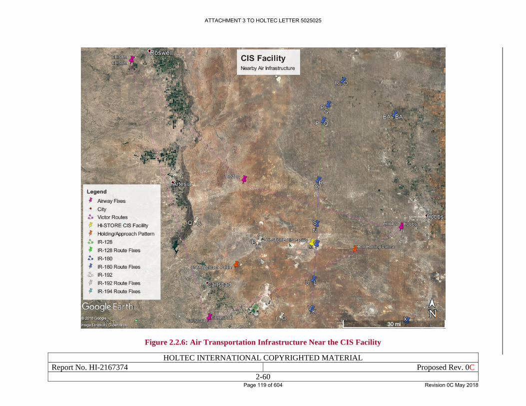
HOLTEC INTERNATIONAL COPYRIGHTED MATERIAL
Report No. HI-2167374 Proposed Rev. 0C
2-60
Figure 2.2.6: Air Transportation Infrastructure Near the CIS Facility
ATTACHMENT 3 TO HOLTEC LETTER 5025025
Page 119 of 604 Revision 0C May 2018
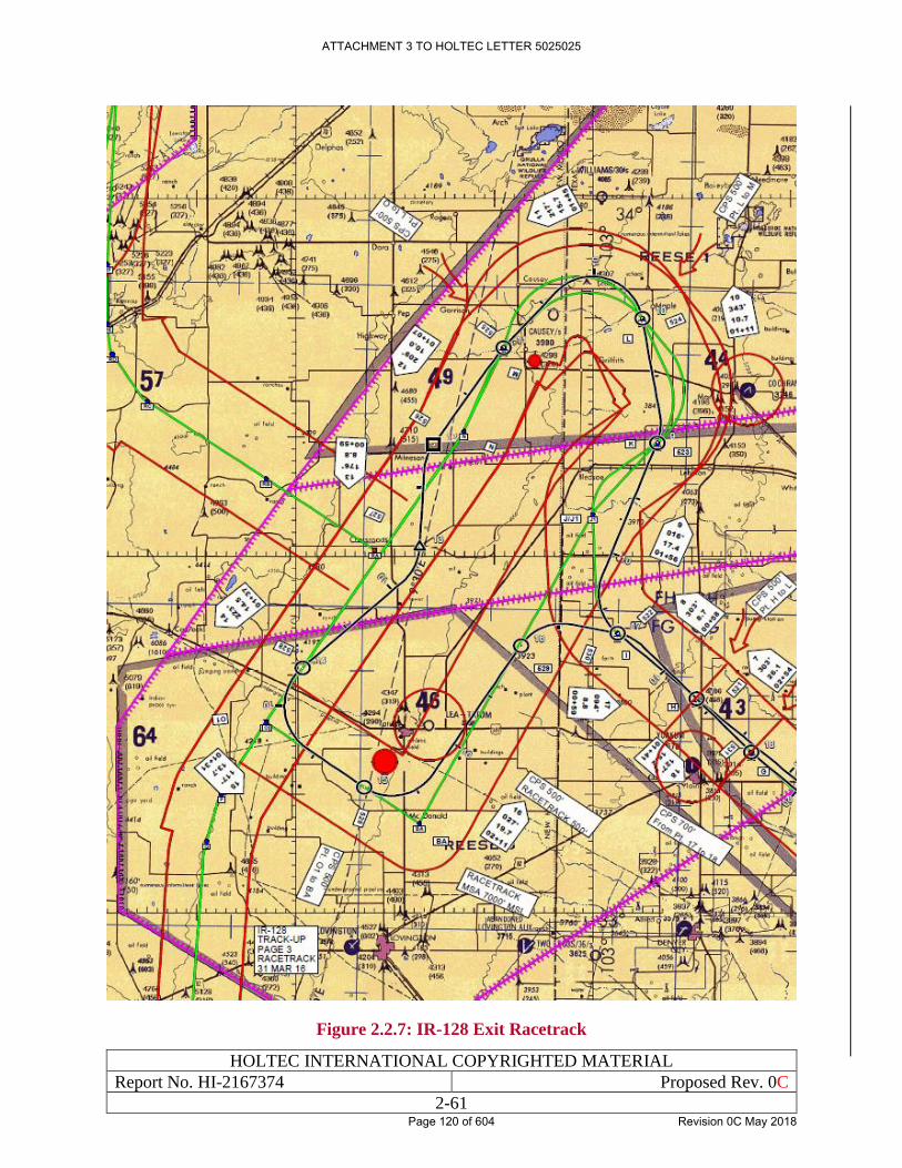
HOLTEC INTERNATIONAL COPYRIGHTED MATERIAL
Report No. HI-2167374 Proposed Rev. 0C
2-61
Figure 2.2.7: IR-128 Exit Racetrack
ATTACHMENT 3 TO HOLTEC LETTER 5025025
Page 120 of 604 Revision 0C May 2018
HOLTEC INTERNATIONAL COPYRIGHTED MATERIAL
Report No. HI-2167374 Proposed Rev. 0C
2-62
2.3 METEOROLOGY
2.3.1 Regional Climatology
The climate at the Site is typically semi-arid with generally mild temperatures, low precipitation,
low humidity, and with a high evaporation rate. The winter weather typically has high pressure
systems that are located in the central part of the western U.S. and low pressure systems located in
north-central Mexico. In the summer, the region is typically affected by low pressure systems
located over Arizona. Overall, precipitation is low and storms are infrequent. Winds during the
spring may cause dust during construction periods; however, it is anticipated to be a minimal and
temporary impact in comparison to the naturally occurring dust.
Meteorological information was obtained from various sources, including the Western Regional
Climate Center (WRCC) and other sources as noted in this section. The use of the data from the
WRCC and other sources are appropriate due to proximity to the proposed Site and are expected
to have similar climates. The WRCC is a governmental department closely associated with the
National Oceanic and Atmospheric Administration (NOAA) and the National Weather Service
(NSW). The data from the WRCC is generally considered to be the authoritative source of
meteorological data for the region (see Appendix A, Section A.2 of the ER [1.0.4] for additional
details regarding the applicability of data from the WRCC).
Temperatures. Data collected over approximately the past 75 years at the Lea County Regional
Airport station [2.3.1] is summarized in Table 2.3.1. The temperature data reported in this
summary table includes monthly average values for the minimum, average, and maximum
temperatures as well as the monthly extreme values for the minimum and maximum temperatures.
Additionally, annual values for these temperature parameters are included.
A site-specific 3-day average ambient temperature is defined by evaluating local weather service
records for the Lea County in which the site is situated. The results are as follows:
• Location: Lea Regional Airport
• Records Period: 1980 – 2017
• Maximum 3-Day Average Temperature: 90.7°F
Winds. Prevailing wind directions and wind speeds at the Lea County Regional Airport station
are presented in Table 2.3.2 and depicted graphically in Figure 2.3.2. The average wind speed is
approximately 12 miles per hour (mph) and the prevailing wind direction is from the south. Winds
are typically moderate, between 1 mph and 19 mph blowing 84 percent of the time, with calm
winds (winds less than 1.3 mph) occurring only approximately 8 percent of the time [2.3.1].
With respect to wind gusts, the average wind speed of all of the maximum gusts is approximately
25 mph. The prevailing wind direction for wind gusts is wind from southwest during 11 percent
of the observations; however, the wind gusts are out of the south, south-southeast, and southeast
during 30 percent of the observations. Typical gusts range in speed from 13 mph to 32 mph,
comprising of 86 percent of the gusts. Gusts range in speed from 32 mph to 47 mph occurred
during 13 percent of the observations, and less than 1 percent of the gusts observed were over 47
mph [2.3.1].
ATTACHMENT 3 TO HOLTEC LETTER 5025025
Page 121 of 604 Revision 0C May 2018
HOLTEC INTERNATIONAL COPYRIGHTED MATERIAL
Report No. HI-2167374 Proposed Rev. 0C
2-63
Mixing Heights. Mixing height is the height above the ground where the strong, vertical mixing
of the atmosphere occurs. G.C. Holzworth developed mean annual morning and afternoon mixing
heights for the contiguous United States [2.3.2]. The results of Holzworth’s calculation methods
for mixing heights include mean annual morning and afternoon mixing heights at the Site of
approximately 1,430 feet and 6,854 feet, respectively [2.3.2]. Table 2.3.3 shows the average
morning and afternoon mixing heights for Midland-Odessa, Texas, which is the nearest available
area with mixing height data, located approximately 100 miles southeast.
Tornadoes. Tornadoes are typically classified by the F-Scale classification. The F-Scale
classification of tornadoes is based on the appearance of the damage that the tornado causes. The
six classifications range from F0 to F5 with an F0 tornado having winds of 40-72 mph and an F5
tornado having winds of 261-318 mph [2.3.3]. Note that as of February 1, 2007, an enhanced F-
scale for tornado damage went into effect in the United States. The switch to the enhanced F-scale
involves:
• Changing the averaging interval for wind speed estimates from the fastest quarter-mile
wind speed to a maximum three-second average wind speed.
• Changing the minimum tornado wind speed from 40 mph to 65 mph.
• Changing the wind speed intervals associated with each F scale class.
The enhanced F-scale uses three-second wind gusts estimated at the point of damage based on a
judgment of eight levels of damage to 28 indicators. The enhanced F-scale has six classifications,
EF0 to EF5, with an EF0 tornado having three-second gusts of 65-85 mph and an EF5 tornado
having three-second gusts of over 200 mph [2.3.4].
Based on a United States-wide study performed on a state by state basis, the average tornado
probability for any F-scale tornado for the Site is between 1x10⁻⁶ and 2x10⁻⁴, as is presented in
Figure 2.3.3 [2.1.3]. Ninety two tornados have occurred in Eddy and Lea counties since 1954. The
highest number of tornados in any given year was 15 in 1991; of which, 14 occurred over a two
day period. The lowest number of tornado in a year has been zero, with a mean average of 1.5
tornados occurring in a year. Most tornados recorded were F0 in scale and occurred in the spring
[2.3.5].
Hurricanes. The Site is located over 500 miles from the oceanic coast. Because hurricanes lose
their intensity quickly once they pass over land, impacts from a hurricane at the Site are unlikely.
Thunderstorms. Thunderstorms can occur during every month of the year, but generally occur
from March through October of each year. Thunderstorms occur an average of 39 days per year in
Carlsbad, New Mexico. The seasonal averages are: 2.7 days in spring (March through May); 8.3
days in summer (June through August); 2.3 days in fall (September through November); and less
than 1 day in winter (December through February) [2.3.1]. Occasionally, thunderstorms are
accompanied by hail [2.1.15].
Precipitation. A summary of precipitation data collected at the Lea County Regional Airport
station resulted in an annual mean average total precipitation of 10.2 inches with monthly mean
average totals ranging from 0.24 inches in March to 1.9 inches in September. The monthly
minimum total is 0.00 inches and the monthly maximum total is 6.2 inches. The highest daily total
is 3.6 inches occurring in December of 2015. A summary of this information is presented in Table
2.3.4 and depicted graphically with monthly average total precipitation in Figure 2.3.4 [2.3.1].
ATTACHMENT 3 TO HOLTEC LETTER 5025025
Page 122 of 604 Revision 0C May 2018
HOLTEC INTERNATIONAL COPYRIGHTED MATERIAL
Report No. HI-2167374 Proposed Rev. 0C
2-64
A summary of snowfall data collected at the Lea County Regional Airport station resulted in an
annual mean average total precipitation of 5.13 inches with monthly mean average totals ranging
from 1.84 inches in February to 0.0 inches from May to October. The monthly minimum total is
0.00 inches and the monthly maximum total is 21.2 inches. The highest daily total is 10.00 inches
occurring in February of 1956 [2.3.1].
Based on the season, atmospheric pressure systems can affect temperature and cause cloud
formation. Clouds are formed when warm, moist air rises into the atmosphere and the droplets are
cooled. When the droplets cool, the water from the air condenses into tiny droplets and forms
clouds. This occurs during low pressure system. These low pressure systems typically occur during
the spring and summer. Climatology data indicate the relative humidity throughout the year ranges
from 45 percent to 61 percent in the region, with the highest humidity occurring during the early
morning hours [2.1.15].
2.3.2 Local Meteorology
There are no on-site weather stations, however due to the proximity of the Lea County Regional
Airport weather station to the Site (approximately 30 miles away), it is reasonable to say that the
data presented in Section 2.3.1 adequately represents the on-site conditions for Local Meteorology.
Additional details regarding the applicability of this data can be seen in Appendix A, Section A.2
of the ER [1.0.4].
2.3.3 Onsite Meteorological Measurement Program
There are no on-site weather stations, however due to the proximity of the Lea County Regional
Airport weather station to the Site (approximately 30 miles away), it is reasonable to say that the
data presented in Section 2.3.1 adequately represents the on-site conditions for Local Meteorology.
Additional details regarding the applicability of this data can be seen in Appendix A, Section A.2
of the ER [1.0.4]. After the license is issued for the CIS Facility, Holtec will establish an on-site
meteorological data collection system. That system will collect, at a minimum, temperature,
precipitation, and wind data.
ATTACHMENT 3 TO HOLTEC LETTER 5025025
Page 123 of 604 Revision 0C May 2018
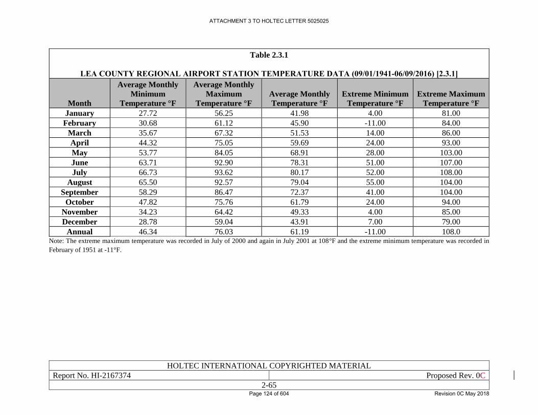
HOLTEC INTERNATIONAL COPYRIGHTED MATERIAL
Report No. HI-2167374 Proposed Rev. 0C
2-65
Table 2.3.1
LEA COUNTY REGIONAL AIRPORT STATION TEMPERATURE DATA (09/01/1941-06/09/2016) [2.3.1]
Month
Average Monthly
Minimum
Temperature °F
Average Monthly
Maximum
Temperature °F
Average Monthly
Temperature °F
Extreme Minimum
Temperature °F
Extreme Maximum
Temperature °F
January 27.72 56.25 41.98 4.00 81.00
February 30.68 61.12 45.90 -11.00 84.00
March 35.67 67.32 51.53 14.00 86.00
April 44.32 75.05 59.69 24.00 93.00
May 53.77 84.05 68.91 28.00 103.00
June 63.71 92.90 78.31 51.00 107.00
July 66.73 93.62 80.17 52.00 108.00
August 65.50 92.57 79.04 55.00 104.00
September 58.29 86.47 72.37 41.00 104.00
October 47.82 75.76 61.79 24.00 94.00
November 34.23 64.42 49.33 4.00 85.00
December 28.78 59.04 43.91 7.00 79.00
Annual 46.34 76.03 61.19 -11.00 108.0 Note: The extreme maximum temperature was recorded in July of 2000 and again in July 2001 at 108°F and the extreme minimum temperature was recorded in
February of 1951 at -11°F.
ATTACHMENT 3 TO HOLTEC LETTER 5025025
Page 124 of 604 Revision 0C May 2018
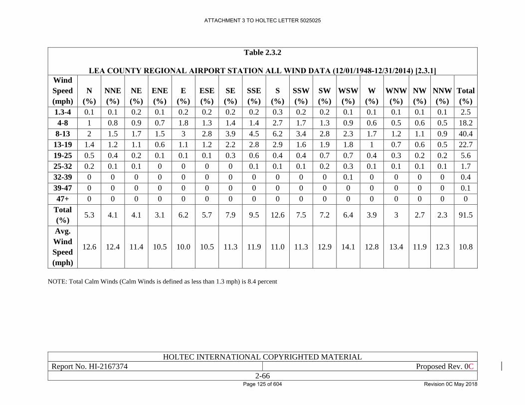
HOLTEC INTERNATIONAL COPYRIGHTED MATERIAL
Report No. HI-2167374 Proposed Rev. 0C
2-66
Table 2.3.2
LEA COUNTY REGIONAL AIRPORT STATION ALL WIND DATA (12/01/1948-12/31/2014) [2.3.1]
Wind
Speed
(mph)
N
(%)
NNE
(%)
NE
(%)
ENE
(%)
E
(%)
ESE
(%)
SE
(%)
SSE
(%)
S
(%)
SSW
(%)
SW
(%)
WSW
(%)
W
(%)
WNW
(%)
NW
(%)
NNW
(%)
Total
(%)
1.3-4 0.1 0.1 0.2 0.1 0.2 0.2 0.2 0.2 0.3 0.2 0.2 0.1 0.1 0.1 0.1 0.1 2.5
4-8 1 0.8 0.9 0.7 1.8 1.3 1.4 1.4 2.7 1.7 1.3 0.9 0.6 0.5 0.6 0.5 18.2
8-13 2 1.5 1.7 1.5 3 2.8 3.9 4.5 6.2 3.4 2.8 2.3 1.7 1.2 1.1 0.9 40.4
13-19 1.4 1.2 1.1 0.6 1.1 1.2 2.2 2.8 2.9 1.6 1.9 1.8 1 0.7 0.6 0.5 22.7
19-25 0.5 0.4 0.2 0.1 0.1 0.1 0.3 0.6 0.4 0.4 0.7 0.7 0.4 0.3 0.2 0.2 5.6
25-32 0.2 0.1 0.1 0 0 0 0 0.1 0.1 0.1 0.2 0.3 0.1 0.1 0.1 0.1 1.7
32-39 0 0 0 0 0 0 0 0 0 0 0 0.1 0 0 0 0 0.4
39-47 0 0 0 0 0 0 0 0 0 0 0 0 0 0 0 0 0.1
47+ 0 0 0 0 0 0 0 0 0 0 0 0 0 0 0 0 0
Total
(%) 5.3 4.1 4.1 3.1 6.2 5.7 7.9 9.5 12.6 7.5 7.2 6.4 3.9 3 2.7 2.3 91.5
Avg.
Wind
Speed
(mph)
12.6 12.4 11.4 10.5 10.0 10.5 11.3 11.9 11.0 11.3 12.9 14.1 12.8 13.4 11.9 12.3 10.8
NOTE: Total Calm Winds (Calm Winds is defined as less than 1.3 mph) is 8.4 percent
ATTACHMENT 3 TO HOLTEC LETTER 5025025
Page 125 of 604 Revision 0C May 2018
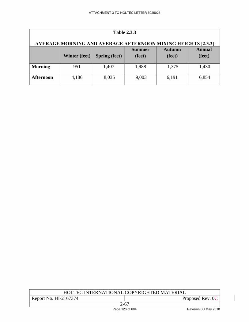
HOLTEC INTERNATIONAL COPYRIGHTED MATERIAL
Report No. HI-2167374 Proposed Rev. 0C
2-67
Table 2.3.3
AVERAGE MORNING AND AVERAGE AFTERNOON MIXING HEIGHTS [2.3.2]
Winter (feet) Spring (feet)
Summer
(feet)
Autumn
(feet)
Annual
(feet)
Morning 951 1,407 1,988 1,375 1,430
Afternoon 4,186 8,035 9,003 6,191 6,854
ATTACHMENT 3 TO HOLTEC LETTER 5025025
Page 126 of 604 Revision 0C May 2018
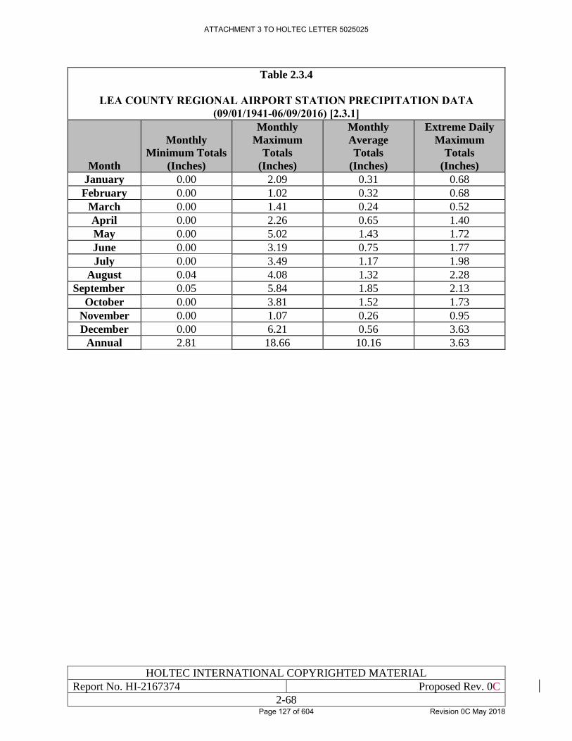
HOLTEC INTERNATIONAL COPYRIGHTED MATERIAL
Report No. HI-2167374 Proposed Rev. 0C
2-68
Table 2.3.4
LEA COUNTY REGIONAL AIRPORT STATION PRECIPITATION DATA
(09/01/1941-06/09/2016) [2.3.1]
Month
Monthly
Minimum Totals
(Inches)
Monthly
Maximum
Totals
(Inches)
Monthly
Average
Totals
(Inches)
Extreme Daily
Maximum
Totals
(Inches)
January 0.00 2.09 0.31 0.68
February 0.00 1.02 0.32 0.68
March 0.00 1.41 0.24 0.52
April 0.00 2.26 0.65 1.40
May 0.00 5.02 1.43 1.72
June 0.00 3.19 0.75 1.77
July 0.00 3.49 1.17 1.98
August 0.04 4.08 1.32 2.28
September 0.05 5.84 1.85 2.13
October 0.00 3.81 1.52 1.73
November 0.00 1.07 0.26 0.95
December 0.00 6.21 0.56 3.63
Annual 2.81 18.66 10.16 3.63
ATTACHMENT 3 TO HOLTEC LETTER 5025025
Page 127 of 604 Revision 0C May 2018
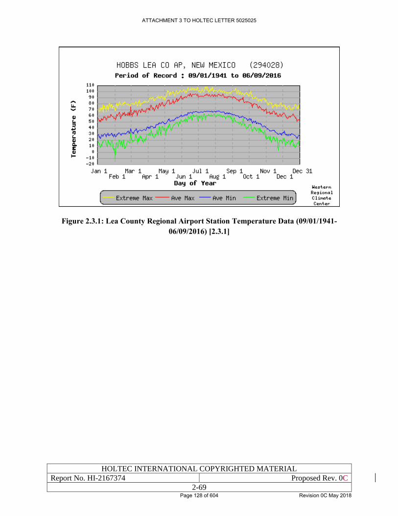
HOLTEC INTERNATIONAL COPYRIGHTED MATERIAL
Report No. HI-2167374 Proposed Rev. 0C
2-69
Figure 2.3.1: Lea County Regional Airport Station Temperature Data (09/01/1941-
06/09/2016) [2.3.1]
ATTACHMENT 3 TO HOLTEC LETTER 5025025
Page 128 of 604 Revision 0C May 2018
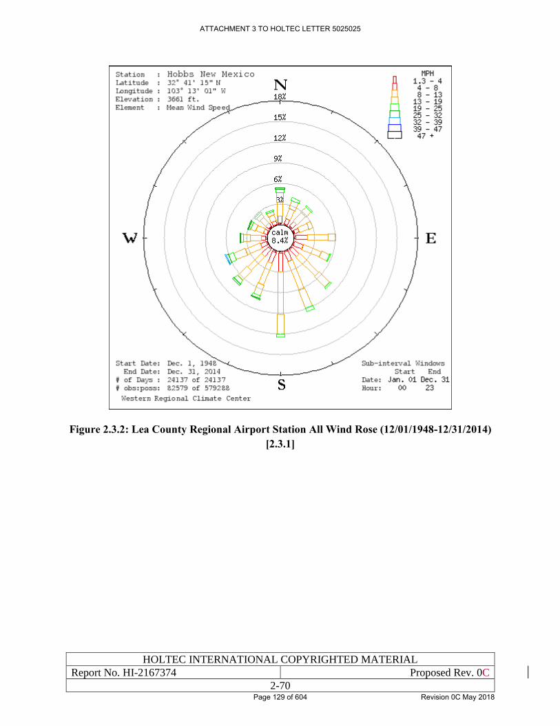
HOLTEC INTERNATIONAL COPYRIGHTED MATERIAL
Report No. HI-2167374 Proposed Rev. 0C
2-70
Figure 2.3.2: Lea County Regional Airport Station All Wind Rose (12/01/1948-12/31/2014)
[2.3.1]
ATTACHMENT 3 TO HOLTEC LETTER 5025025
Page 129 of 604 Revision 0C May 2018
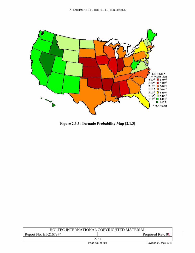
HOLTEC INTERNATIONAL COPYRIGHTED MATERIAL
Report No. HI-2167374 Proposed Rev. 0C
2-71
Figure 2.3.3: Tornado Probability Map [2.1.3]
ATTACHMENT 3 TO HOLTEC LETTER 5025025
Page 130 of 604 Revision 0C May 2018
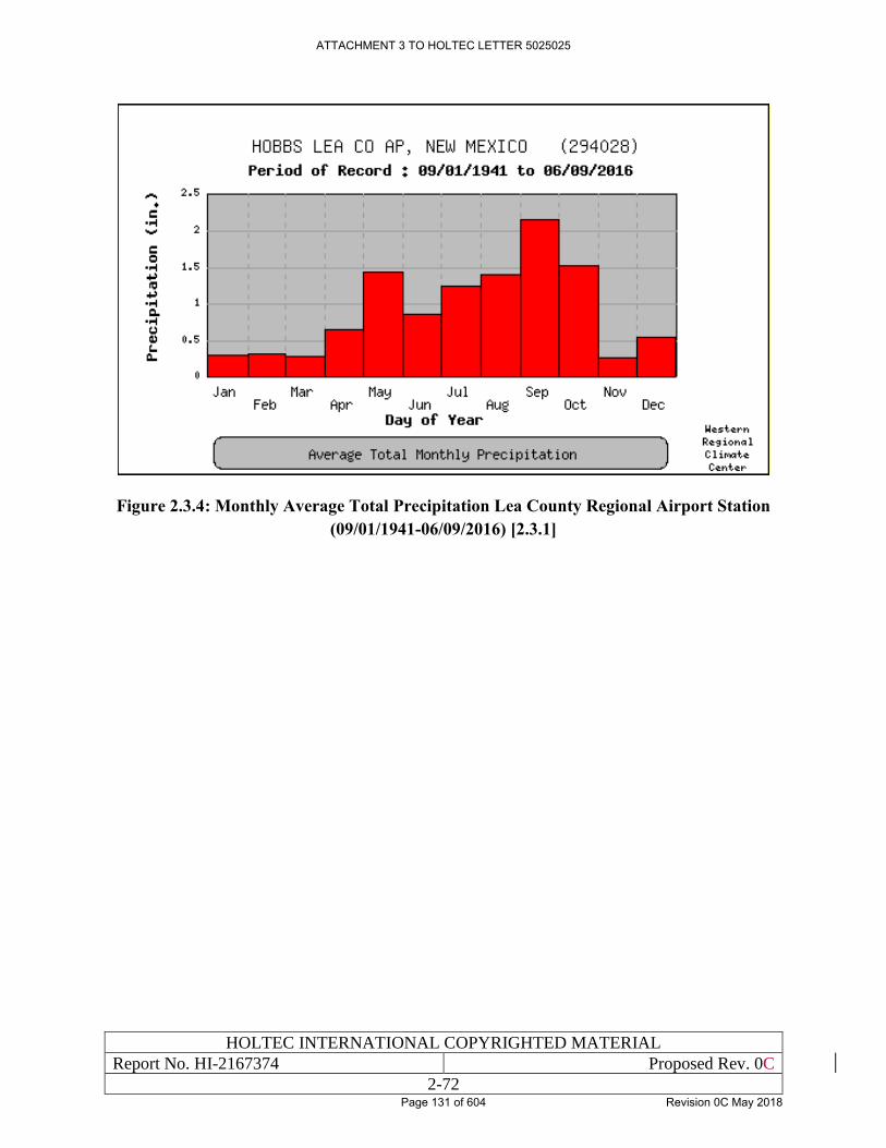
HOLTEC INTERNATIONAL COPYRIGHTED MATERIAL
Report No. HI-2167374 Proposed Rev. 0C
2-72
Figure 2.3.4: Monthly Average Total Precipitation Lea County Regional Airport Station
(09/01/1941-06/09/2016) [2.3.1]
ATTACHMENT 3 TO HOLTEC LETTER 5025025
Page 131 of 604 Revision 0C May 2018
HOLTEC INTERNATIONAL COPYRIGHTED MATERIAL
Report No. HI-2167374 Proposed Rev. 0C
2-73
2.4 SURFACE HYDROLOGY
2.4.1 Hydrologic Description
The Site lies within the Pecos River Basin (see Figure 3.5.1 of the ER [1.0.4]), which has a
maximum basin width of 130 miles, and a drainage area of 44,535 square miles. There are no
surface-water bodies or surface-drainage features on the proposed CIS Facility Site. The Pecos
River is the closest surface water feature to the Site. At its nearest approach, the distance from the
Site to the Pecos River is 26 miles. In Lea County neither of the two major drainage basins, the
Texas Gulf Basin in the north and east and the Pecos River Basin in the south and west, contain
large-scale surface-water bodies or through-flowing drainage systems. The surface water supplies
that exist are transitory and limited to quantities of runoff impounded in short drainage ways,
shallow lakes, and small depressions, including various playas and lagunas. The Texas Gulf Basin
contains a lake, the Llano Estacado, and the Simona Valley. The Pecos River Basin contains the
Querecho Plains, the Eunice Plains, and the Antelope Ridge [2.4.1, Section 2.5.1].
The CIS Facility Site is contained within the Upper Pecos-Black watershed; however, there are no
freshwater lakes, estuaries, or oceans in the vicinity of the site (Figure 2.4.1). Local surface
hydrologic features in the vicinity of the site include a cluster of four saline playas that are located
in the Querecho Plain area of the west-central part of the county. These playas, which retain runoff
temporarily, are referred to locally as lagunas. Laguna Plata covers the largest area, about 2 square
miles. Laguna Toston, the smallest of the four with a surface area of one-quarter square mile, is
completely filled with sediments; the other three all contain accumulations of clastic sediments
and salts (halite, gypsum) [2.4.5; 2.4.1, Section 2.5.1]. Surface runoff from the Site flows into
Laguna Gatuna to the east and Laguna Plata to the northwest [2.1.3]. Surface drainage at the
proposed Site is contained within two local playa lakes that have no external drainage. These
playas are generally dry, but retain runoff temporarily [2.1.3]. Runoff does not drain to one of the
state’s major rivers. Figures 2.4.2 and 2.4.3 show hydrologic features in the vicinity of the CIS
Facility.
The lagunas help to create shallow saline ground-water which exists under much of the Querecho
Plain. Surface water is lost through evaporation, resulting in high salinity conditions in soils
associated with the playas. These conditions are not favorable for the development of viable
aquatic or riparian habitats. The presence of the shallow saline water has been recognized to the
extent that the New Mexico Oil Conservation Commission Order No. R-3221, banning the surface
disposal of produced water into unlined pits within the State was amended (OCC Order No. R-
3221-B, July 25, 1968) to exclude much of the area [2.4.5; 2.4.6].
Laguna Gatuna is located on the eastern boundary of the Site. Laguna Gatuna is an ephemeral
playa that covers a surface area of 0.54 square miles, has an average depth of 10 feet, and a total
shore line of 4 miles. The lake, which sits at an elevation of 3,495 feet drains a watershed that
covers 170 square miles. Laguna Gatuna was the site of multiple facilities for collection and
discharge of brines that were co-produced from oil and gas wells in the entire area; facility permits
authorized discharge of almost one million barrels of oilfield brine per month between 1969 and
1992. As a result, saturations of shallow groundwater brine have been created in a number of areas
associated with the playa lakes [2.4.1, Section 2.4.2.1].
ATTACHMENT 3 TO HOLTEC LETTER 5025025
Page 132 of 604 Revision 0C May 2018
HOLTEC INTERNATIONAL COPYRIGHTED MATERIAL
Report No. HI-2167374 Proposed Rev. 0C
2-74
Laguna Tonto is located approximately 2.5 miles northeast of the Site. Laguna Tonto is an
ephemeral playa that covers a surface area of 0.28 square miles, has an average depths of 12 feet,
and has a total shore line of 2 miles. The playa, which sits at an elevation of 3,531 feet, drains a
watershed that covers 49 square miles.
Laguna Plata is located approximately 1.8 miles northwest of the Site. Laguna Plata is an
ephemeral playa that covers a surface area of 2 square miles, has an average depth of 14 feet, and
has a total shore line of 6 miles. The playa, which sits at an elevation of 3,432 feet, drains a
watershed that covers 254 square miles. Laguna Plata is the largest of the playas in the vicinity of
the site with a total water volume of approximately 14,593 acre-feet. Laguna Plata is the
topographically lowest point in the area and alluvial groundwater appears to flow toward this site
[2.4.1, Section 2.4].
Laguna Toston is the smallest of the playas in the vicinity of the CIS Facility Site with a surface
area of one-quarter mile. The playa is a major input point for potash refinery brine and water
appears to drain radially away from this location [2.4.1, Section 2.4].
The U.S. Geological Survey (USGS) does not have permanent stream gages in Lea County which
measure daily surface flows. However, peak flow rates have been spot measured at Monument
Draw (near Monument) and Antelope Draw (near Jal). Each of these Draws can occasionally
convey sizable flows. In June of 1972, a flow of 1280 cubic feet per second (CFS) (the highest
recorded) occurred at Monument Draw. In July of 1994, a flow of 530 CFS (also the highest
recorded) occurred at Antelope Draw. These flows should be considered indicative of flows that
can occur at other gullies and swales in Lea County (Lea County 2016, 1999).
The proposed CIS Facility Site is not located near any floodplains. The Site is located in an area
of Lea County designated as “Zone D”. The “Zone D” designation is used for areas where there
are possible but undetermined flood hazards, as no analysis of flood hazards has been conducted
or when a community incorporates portions of another community’s area where no map has been
prepared [2.4.3]. A digital version of the map panel for the CIS Facility location in the National
Flood Hazard Layer is presented in Figure 2.4.4 [2.4.3]. Other than the playas, the nearest surface
water is the Pecos River which is west of the Site. Like most rivers in New Mexico, the Pecos
River is described as “extremely variable from year-to-year” due to its dependence on runoff. The
principle use of Pecos River water is for agriculture. There are no sensitive or unique aquatic or
riparian habitats or wetlands at the Site, nor is there surface water in the vicinity that is potable
[2.1.3].
Groundwater within Lea County is provided primarily by the High Plains Aquifer composed of
the Ogallala Formation. Cretaceous and Triassic rocks underlying the Ogallala Formation limit
downward percolation from the Ogallala Aquifer. The region includes portions of five declared
underground water basins (UWBs): Capitan, Carlsbad, Jal, Lea County, and Roswell. (A declared
UWB is an area of the state proclaimed by the State Engineer to be underlain by a groundwater
source having reasonably ascertainable boundaries. By such proclamation the State Engineer
assumes jurisdiction over the appropriation and use of groundwater from the source.) The Jal UWB
falls entirely within the Lea County region, but the other four are shared with the Lower Pecos
Valley region, although only a small portion of the Lea County UWB extends into the Lower Pecos
Valley region, and Lea County overlies only a small extension of the Roswell Basin [2.4.6].
ATTACHMENT 3 TO HOLTEC LETTER 5025025
Page 133 of 604 Revision 0C May 2018
HOLTEC INTERNATIONAL COPYRIGHTED MATERIAL
Report No. HI-2167374 Proposed Rev. 0C
2-75
The CIS Facility Site is within the Capitan UWB (Figure 2.4.5) and lies within the Upper Pecos-
Black Watershed which is part of the Pecos River Basin (Figure 2.4.6). The Capitan UWB covers
approximately 1,100 square miles and occupies the south-central portion of Lea County. The
Capitan UWB is located within a geologic province known as the Delaware Basin, a subdivision
of the Permian Basin. The Capitan UWB is aerially oriented in a northwest-southeast alignment
above an arc shaped section of a formation known as the Capitan Reef Complex. The Capitan
aquifer occurs within dolomite and limestone strata deposited as an ancient reef. The ground-water
quality of the Capitan in Lea County is very poor. Other aquifers in the Capitan UWB are found
in the overlying Rustler Formation4, Santa Rosa Sandstone5, and Cenozoic Alluvium. The primary
uses of ground-water from the Capitan UWB are mining, oil recovery, industry, livestock, and
domestic use. The towns of Eunice and Jal are located within the Capitan UWB, but currently tap
beds of saturated Quaternary alluvium located within the Lea County UWB and Jal UWB
respectively [2.4.5].
The site topography is irregular, with a slight slope toward the north, with elevations ranging
between about 3,500 and 3,550 feet above mean sea level [2.4.4]. Based on a review of the USGS
topographic map, the elevation at the CIS Facility Site is approximately 3,530 feet above mean sea
level. Several shallow depressions are shown along the western portions of the Site. Figure 2.4.7
illustrates local topography in the area of the proposed CIS Facility Site. A topographic high is
present within the central portion of the property with ephemeral washes draining from this point;
one to the west into Laguna Plata and another to the east into Laguna Gatuna. Both of these
drainages would be able to accept a one day severe storm total within the 7.5 inch range with
excess free board space. The natural drainage of the Site is useful by providing a natural area for
impoundment of excess runoff during severe storms [2.4.1].
The Project area is classified as Apacherian-Chihuahuan mesquite upland scrub [2.4.8]. This
ecosystem often occurs as invasive upland shrublands such as those that are concentrated in the
foothills and piedmonts of the Chihuahuan Desert [2.4.7]. Substrates are typically derived from
alluvium, often gravelly without a well-developed argillic or calcic soil horizon that would limit
infiltration and storage of winter precipitation in deeper soil layers. Deep-rooted shrubs are able
to access the deep-soil moisture that is unavailable to grasses and cacti. Water held in storage in
the soil is subsequently subject to evapotranspiration. Historical periods of high temperature and
low precipitation in Lea County have resulted in high demands for irrigation water and higher open
water evaporation and riparian evapotranspiration [2.4.6]. Evapotranspiration at the Site is five
times the precipitation rate, indicating that there is little infiltration of precipitation into the
subsurface. Surface drainage at the Site is contained within two local playa lakes that have no
external drainage. Runoff does not drain to one of state’s major rivers. Essentially all the
precipitation that occurs at the Site is subject to infiltration and/or evapotranspiration.
No major surface water supplies are available in Lea County, only intermittent streams, lakes,
stock ponds, and small playas that collect runoff during thunderstorms. Intermittent streams that
channel runoff include Lost Draw, Sulfur Springs Draw, and Monument-Seminole Draw in the
northern half of Lea County, which is part of the Texas Gulf Basin, and Landreth-Monument Draw
in the southern portion of the county, which flows to the Pecos River. The Site lies within the
Pecos River Basin as depicted in Figure 2.4.8, which has a maximum basin width of 130 miles,
and a drainage area of 44,535 square miles. The Pecos River generally flows year-round. The main
ATTACHMENT 3 TO HOLTEC LETTER 5025025
Page 134 of 604 Revision 0C May 2018
HOLTEC INTERNATIONAL COPYRIGHTED MATERIAL
Report No. HI-2167374 Proposed Rev. 0C
2-76
stem of the Pecos River and its major tributaries have low flows, and the tributary streams are
frequently dry. Seventy-five percent of the total annual precipitation and 60 percent of the annual
flow result from intense local thunderstorms between April and September. Due to the seasonal
nature of the rainfall, most surface drainage is intermittent. There are no surface-water bodies or
surface-drainage features on the proposed CIS Facility Site. The intermittent surface drainages,
lakes, and watersheds in Lea County are shown on Figure 2.4.8 [2.4.6].
The USGS does not have permanent stream gages in Lea County which measure daily surface
flows. However, peak flow rates have been spot measured at Monument Draw (near Monument)
and Antelope Draw (near Jal). Each of these Draws can occasionally convey sizable flows. In June
of 1972, a flow of 1,280 cubic feet per second (cfs) (the highest recorded) occurred at Monument
Draw. In July of 1994, a flow of 530 cfs (also the highest recorded) occurred at Antelope Draw.
These flows should be considered indicative of flows that can occur at other gullies and swales in
Lea County [2.4.5; 2.4.6].
The proposed CIS Facility Site is not located near any floodplains. The Site is located in an area
of Lea County designated as “Zone D”. The “Zone D” designation is used for areas where there
are possible but undetermined flood hazards, as no analysis of flood hazards has been conducted
or when a community incorporates portions of another community’s area where no map has been
prepared [2.4.3]. A digital version of the map panel for the CIS Facility location in the National
Flood Hazard Layer is presented in Figure 2.4.9 [2.4.3].
There are no wetlands on the proposed CIS Facility Site. Wetlands in the vicinity of the CIS
Facility are shown on Figure 2.4.10.
As further discussed in sections 2.4.2 and 2.4.3, the Site can be considered “flood-dry” and
therefore it can be concluded that none of the facilities important to safety structures will be
affected by the Site’s hydrologic features. Additionally, there are no surface water bodies on the
Site and groundwater resources are at depths of approximately 300 to 400 feet, therefore no
population groups are affected by normal Site operations.
2.4.2 Floods
Floodplains are areas of low-level ground present along rivers, stream channels, or coastal waters
subject to periodic or infrequent inundation due to rain or melting snow. Risk of flooding typically
depends on local topography, the frequency of precipitation events, and the size of the watershed
above the floodplain. Flood potential is evaluated by the Federal Emergency Management Agency
(FEMA), which defines the 100-year floodplain as an area that has a one percent chance of
inundation by a flood event in any given year. Federal, state, and local regulations often limit
floodplain development to passive uses such as recreational and preservation activities to reduce
the risks to human health and safety. Floodplain ecosystem functions include natural moderation
of floods, flood storage and conveyance, groundwater recharge, nutrient cycling, water quality
maintenance, and diversification of plants and animals.
The proposed Site or Lea County has no floodplain identified or mapped for Lea County, New
Mexico [2.1.6, 2.1.7]. Elevations in Lea County vary from 2,900 feet in the southeast to 4,400 feet
in the northwest. This relief provides two surface water drainage basins in the county. The Texas
Gulf Basin, located in the northern portion of Lea County, and the Pecos River Basin, located in
ATTACHMENT 3 TO HOLTEC LETTER 5025025
Page 135 of 604 Revision 0C May 2018
HOLTEC INTERNATIONAL COPYRIGHTED MATERIAL
Report No. HI-2167374 Proposed Rev. 0C
2-77
the southern portion of the county, is separated by the Mescalero Ridge and its extended
escarpment [2.1.3].
In Lea County neither of the two major drainage basins, the Texas Gulf Basin in the north and east
and the Pecos River Basin in the south and west, contain large-scale surface-water bodies or
through-flowing drainage systems. The surface water supplies that exist are transitory and limited
to quantities of runoff impounded in short drainage ways, shallow lakes, and small depressions,
including various playas and lagunas [2.1.3].
The topography of the Site shows a high point located on the southern border of the Site and gentle
slopes leading to the two drainages (Laguna Plata and Laguna Gatuna). Both of these drainages
would be able to accept a one day severe storm total within the 7.5 inch range with excess free
board space. The natural drainage of the Site is useful by providing a natural area for impoundment
of excess runoff during severe storms [2.1.3].
A site-specific flood analysis of the maximum precipitation event was prepared. The objective of
this study was to determine the amount of flooding that would occur at the project site (as seen in
Figure 2.4.11) with 7.5 inches of rain during a 24-hour period using publicly available GIS data.
The boundary of the site (defined as Area of Interest (AOI)) was provided. All other GIS data for
the analysis were identified, derived, and/or acquired from publicly available data sources. This
data included a Digital Elevation Model (DEM) of the AOI, one foot contours of the area (derived
from the DEM), hydrologic unit boundary for the 12-digit sub-watersheds (HUC-12), and the
NRCS soils present in the AOI [2.4.9; 2.4.10; 2.4.11]. Also derived from the DEM was a
Triangular Interpolated Network (TIN) layer used in the polygon volume calculations. All data
were projected into the NAD83, UTM Zone 13N coordinate system.
The flooding analysis was conducted with ESRI ArcGIS for Desktop software, version 10.2.2,
with 3D and Spatial Analyst extensions. The HUC-12 sub-watersheds layer was assessed for
proximity to the site, and two sub-watersheds were identified as relevant basins (i.e., Laguna
Grande and Laguna Plata Watersheds). The Laguna Gatuna and Laguna Plata wetlands both were
the downslope point of catchment for their respective watersheds. Acreage was calculated for each
of these watersheds, and the watersheds were buffered to eliminate edge effects of contour
creation. Two DEMs (east and west, corresponding to Laguna Grande and Laguna Plata,
respectively) were extracted from the buffered layers and contours were created at one foot
intervals.
The NRCS soils layer was clipped to the watershed boundaries. The soil attributes of concern,
Depth to Restrictive Layer (depth to impermeable bedrock in centimeters, “Dep2ResLyr”) and
Saturated Hydraulic Conductivity (Ksat in µm/second) were extracted and consolidated into one
layer. The Ksat values were used from the top 0-80 inch active soil zone. The infiltration level
(Ksat) was converted into inches of water absorbed per 24 hour period, and the Dep2ResLyr
converted to inches. The restrictive depth was then halved to add conservatism, and 7.5 inches
was subtracted from this value. Area where saturation and run-off occurred within the 24-hour/7.5
inch rain event were calculated for these soil types, normalized for feet, and multiplied by the
ATTACHMENT 3 TO HOLTEC LETTER 5025025
Page 136 of 604 Revision 0C May 2018
HOLTEC INTERNATIONAL COPYRIGHTED MATERIAL
Report No. HI-2167374 Proposed Rev. 0C
2-78
acreage for the respective watersheds, yielding acre-feet of runoff that were converted to cubic
feet of runoff. These values were 23,379,663.14 ft3 (Laguna Gatuna eastern wetland basin) and
15,508,872.72 ft3 (Laguna Plata western wetland basin). These volumes were used to determine
the level of flooding in each watershed.
A TIN was created from watershed’s DEM. This provided a 3D functional surface representing
elevations over the watershed and was used as an input for polygon volume calculation. From the
contour layers, polygons were created in an ascending order of elevations from the lowest level in
each laguna. The Polygon Volume tool was run iteratively on these polygons, calculating the
volume between the polygon and the TIN surface. Based on the watershed and hydrologic
modeling the results of the analysis show the volume of flooding in the eastern Laguna Gatuna
would rise 5 feet from 3,500 feet to an elevation of 3,505 feet. The volume of flooding in the
western Laguna Plata would rise 2 feet from 3,427 feet to an elevation of 3,429 feet. The Project
site is bisected by the two sub-watersheds. The lowest elevation of the Project site on the west side
is 3,501 feet which is 72 feet above the modeled flood elevation, and the east side is 3,523 feet
which is 18 feet above the modeled flood elevation. In summary, this analysis indicates that the
Project site will not flood during a 24-hour/7.5 inch rain event even with 50% reduction in the soil
saturation capacity/depth to restriction which was added into this model as a conservative measure.
It should be noted that the model assumes that the playas were dry prior to the 24-hour/7.5 inch
rain event.
2.4.3 Probable Maximum Flood (PMF)
Because there are no significant bodies of water or rivers within 50 miles of the Site, the only
plausible flooding hazard to the Site is from stormwater runoff during rain events. To estimate the
potential effects of rainfall-induced stormwater runoff, Holtec reviewed precipitation data for the
area spanning more than 50-years (see Paragraph 3.6.1.7 of the ER [1.0.4]), as well as other
available data developed for other nuclear facilities in the area. The highest daily precipitation in
the area was 3.6 inches, which occurred in December of 2015 [1.0.4].
The topography of the CIS Facility Site is irregular, with a slight slope toward the north. A
topographic high is present within the central portion of the property with ephemeral washes
draining from this point; one to the west into Laguna Plata and another to the east into Laguna
Gatuna. Based on a review of the USGS topographic map, the elevation at the Site is
approximately 3,530 feet above mean sea level. Several shallow depressions are shown along the
western portions of the Site. The Site is not within the 100-year and 500-year floodplains. Table
2.4.1 provides estimates of the 24-hour 100-year rain event for the Hobbs, New Mexico.
As discussed in Section 2.4.2, drainages on the Site would be able to accept a one day severe storm
total within the 7.5 inch range with excess free board space. Because the Site’s drainage areas can
handle a greater maximum flood height than what the PMF has been determined to be, the site can
be considered to be “flood-dry”.
ATTACHMENT 3 TO HOLTEC LETTER 5025025
Page 137 of 604 Revision 0C May 2018
HOLTEC INTERNATIONAL COPYRIGHTED MATERIAL
Report No. HI-2167374 Proposed Rev. 0C
2-79
Per Table 2.3.1 of the HI-STORM UMAX FSAR [1.0.6], the HI-STORM UMAX System is able
to withstand a maximum flood height of 125 ft. Therefore, all ITS components of the system can
be considered safe from flooding concerns.
With regard to the potential for surface erosion from flooding at the Site, as discussed in Section
4.3 of the ER [1.0.4], soils at the Site are considered to be only slightly susceptible to water erosion.
2.4.4 Potential Dam Failures (Seismically-Induced)
The nearest dams are Brantley Dam, approximately 38 miles, and Avalon Dam, approximately 31
miles from the proposed Site. Both dams are at an elevation more than 500 feet below the Site. As
a result of the large distances to the nearest bodies of water, these bodies of water do not present a
credible disruptive event for the proposed Site.
2.4.5 Probable Maximum Surge and Seiche Flooding
There are no significant bodies of water or rivers within 50 miles of the Site and seiche flooding
is excluded as a potential flood hazard.
2.4.6 Probable Maximum Tsunami Flooding
The Site is approximately 500 miles from any coastal area and tsunamis are excluded as a potential
flood hazard.
2.4.7 Ice Flooding
The mean annual snowfall is 5.1 inches recorded at the Hobbs weather station. The maximum
recorded snow accumulation for Hobbs, NM, is 12.2 inches, and a 100-year, 2-day snowfall is 12.1
inches [2.4.14]. The Site is not subject to flooding caused by ice jams. In the winter, during those
periods when the playas are retaining temporary runoff, freezing of the retained water can occur.
2.4.8 Flood Protection Requirements
Because the flooding analyses do not indicate that the Site would be subject to flooding, there are
no flood protection requirements.
2.4.9 Environmental Acceptance of Effluents
As stated in Chapter 14, the canister storage system does not create any radioactive materials or
have any radioactive waste treatment system and thus provides assurance that there are no
radioactive effluents from the spent fuel storage system. Additionally, surface drainage at the
proposed Site is contained within two local playa lakes that have no external drainage. Evapo-
transpiration at the Site is five times the precipitation rate, indicating that there is little infiltration
of precipitation into the subsurface. The near surface water table is approximately 35-50 feet deep,
where present and is likely controlled by the water level in the playa lakes. Therefore, there is little
to no risk of effluents of any kind being accepted by the environment.
ATTACHMENT 3 TO HOLTEC LETTER 5025025
Page 138 of 604 Revision 0C May 2018
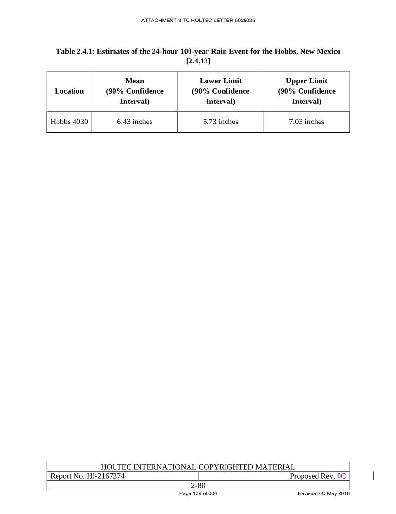
HOLTEC INTERNATIONAL COPYRIGHTED MATERIAL
Report No. HI-2167374 Proposed Rev. 0C
2-80
Table 2.4.1: Estimates of the 24-hour 100-year Rain Event for the Hobbs, New Mexico
[2.4.13]
Location
Mean
(90% Confidence
Interval)
Lower Limit
(90% Confidence
Interval)
Upper Limit
(90% Confidence
Interval)
Hobbs 4030 6.43 inches 5.73 inches 7.03 inches
ATTACHMENT 3 TO HOLTEC LETTER 5025025
Page 139 of 604 Revision 0C May 2018
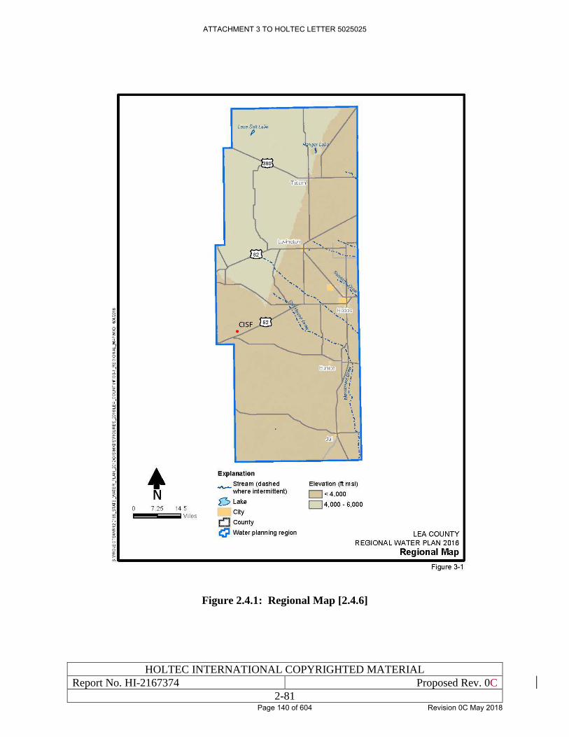
HOLTEC INTERNATIONAL COPYRIGHTED MATERIAL
Report No. HI-2167374 Proposed Rev. 0C
2-81
Figure 2.4.1: Regional Map [2.4.6]
ATTACHMENT 3 TO HOLTEC LETTER 5025025
Page 140 of 604 Revision 0C May 2018
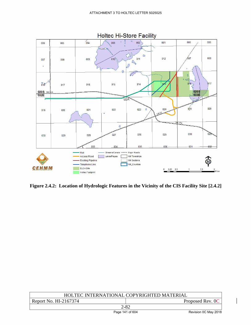
HOLTEC INTERNATIONAL COPYRIGHTED MATERIAL
Report No. HI-2167374 Proposed Rev. 0C
2-82
Figure 2.4.2: Location of Hydrologic Features in the Vicinity of the CIS Facility Site [2.4.2]
ATTACHMENT 3 TO HOLTEC LETTER 5025025
Page 141 of 604 Revision 0C May 2018
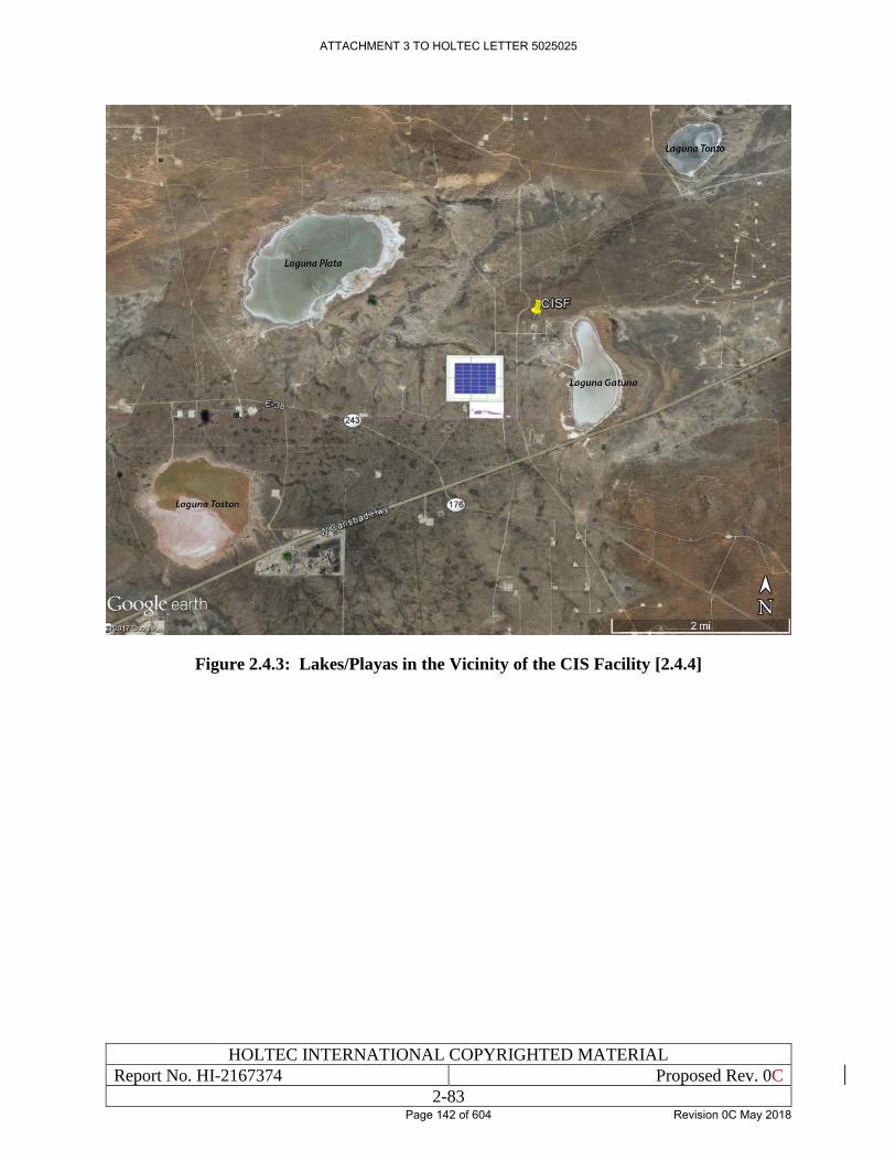
HOLTEC INTERNATIONAL COPYRIGHTED MATERIAL
Report No. HI-2167374 Proposed Rev. 0C
2-83
Figure 2.4.3: Lakes/Playas in the Vicinity of the CIS Facility [2.4.4]
ATTACHMENT 3 TO HOLTEC LETTER 5025025
Page 142 of 604 Revision 0C May 2018
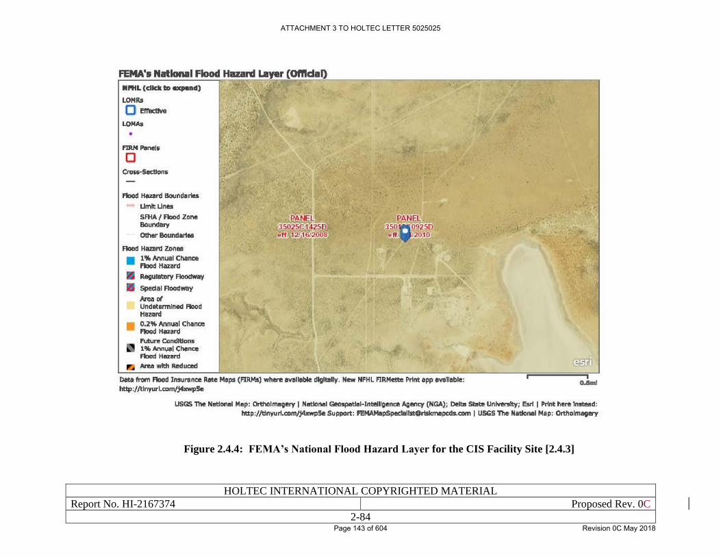
HOLTEC INTERNATIONAL COPYRIGHTED MATERIAL
Report No. HI-2167374 Proposed Rev. 0C
2-84
Figure 2.4.4: FEMA’s National Flood Hazard Layer for the CIS Facility Site [2.4.3]
ATTACHMENT 3 TO HOLTEC LETTER 5025025
Page 143 of 604 Revision 0C May 2018
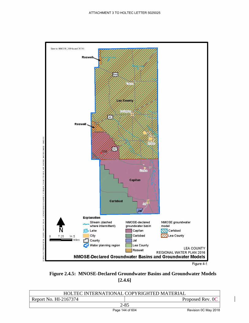
HOLTEC INTERNATIONAL COPYRIGHTED MATERIAL
Report No. HI-2167374 Proposed Rev. 0C
2-85
Figure 2.4.5: MNOSE-Declared Groundwater Basins and Groundwater Models
[2.4.6]
ATTACHMENT 3 TO HOLTEC LETTER 5025025
Page 144 of 604 Revision 0C May 2018
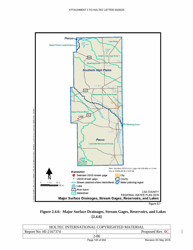
HOLTEC INTERNATIONAL COPYRIGHTED MATERIAL
Report No. HI-2167374 Proposed Rev. 0C
2-86
Figure 2.4.6: Major Surface Drainages, Stream Gages, Reservoirs, and Lakes
[2.4.6]
ATTACHMENT 3 TO HOLTEC LETTER 5025025
Page 145 of 604 Revision 0C May 2018
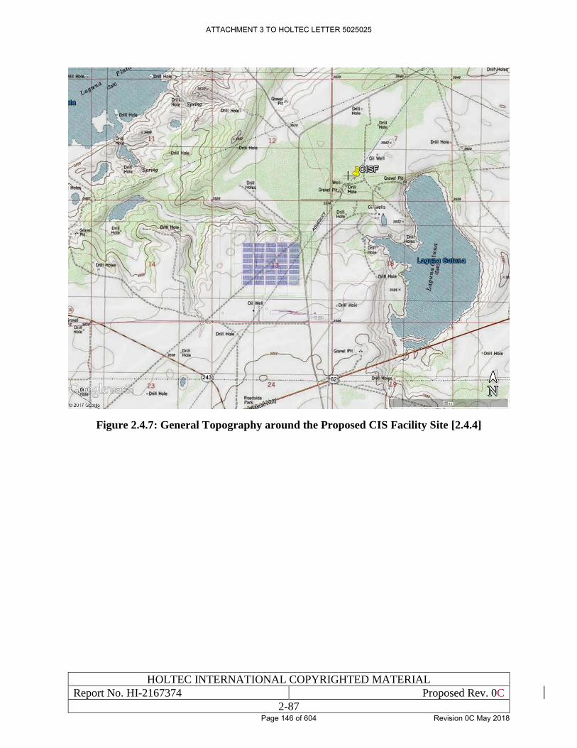
HOLTEC INTERNATIONAL COPYRIGHTED MATERIAL
Report No. HI-2167374 Proposed Rev. 0C
2-87
Figure 2.4.7: General Topography around the Proposed CIS Facility Site [2.4.4]
ATTACHMENT 3 TO HOLTEC LETTER 5025025
Page 146 of 604 Revision 0C May 2018
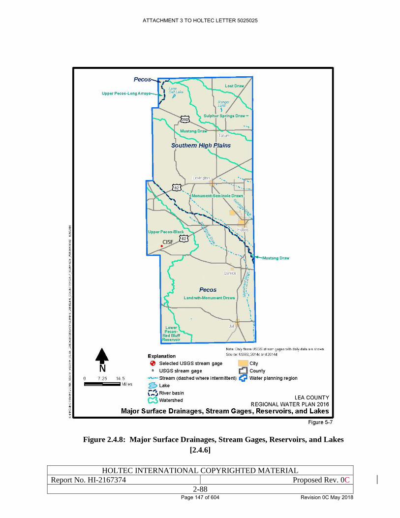
HOLTEC INTERNATIONAL COPYRIGHTED MATERIAL
Report No. HI-2167374 Proposed Rev. 0C
2-88
Figure 2.4.8: Major Surface Drainages, Stream Gages, Reservoirs, and Lakes
[2.4.6]
ATTACHMENT 3 TO HOLTEC LETTER 5025025
Page 147 of 604 Revision 0C May 2018
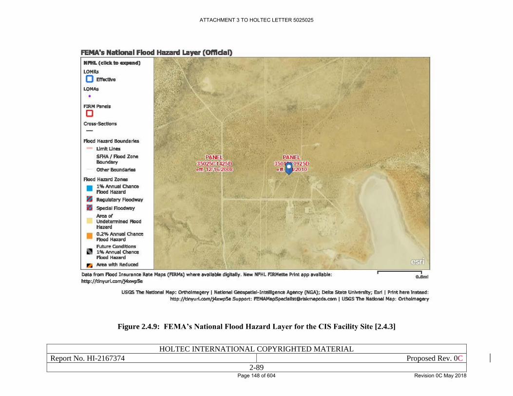
HOLTEC INTERNATIONAL COPYRIGHTED MATERIAL
Report No. HI-2167374 Proposed Rev. 0C
2-89
Figure 2.4.9: FEMA’s National Flood Hazard Layer for the CIS Facility Site [2.4.3]
ATTACHMENT 3 TO HOLTEC LETTER 5025025
Page 148 of 604 Revision 0C May 2018
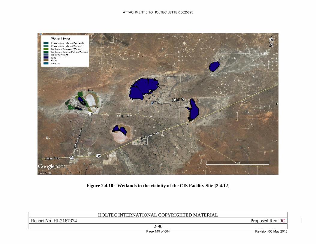
HOLTEC INTERNATIONAL COPYRIGHTED MATERIAL
Report No. HI-2167374 Proposed Rev. 0C
2-90
Figure 2.4.10: Wetlands in the vicinity of the CIS Facility Site [2.4.12]
ATTACHMENT 3 TO HOLTEC LETTER 5025025
Page 149 of 604 Revision 0C May 2018
HOLTEC INTERNATIONAL COPYRIGHTED MATERIAL
Report No. HI-2167374 Proposed Rev. 0C
2-91
2.5 SUBSURFACE HYDROLOGY
The Site is located in the Capitan Underground Water Basin (UWB) as shown in Figure 2.5.1
[2.5.1]. A declared groundwater basin is an area of the state proclaimed by the State Engineer to
be underlying a groundwater source having reasonably ascertainable boundaries. By such
proclamation, the State Engineer assumes jurisdiction over the appropriation and use of
groundwater from the source. The Capitan UWB covers approximately 731,500 acres in the south-
central portion of Lea County. It is located within a geologic province known as the Delaware
Basin, a subdivision of the Permian Basin. The Capitan UWB is oriented in a northwest-southeast
alignment above an arc-shaped section of a formation known as the Capitan Reef Complex. The
Capitan aquifer occurs within dolomite and limestone strata deposited as an ancient reef. The
groundwater quality of the Capitan in Lea County is very poor, with total dissolved solids ranging
from 10,065 to 165,000 milligrams per liter (mg/L).
Other aquifers in the Capitan UWB are found in the overlying Rustler Formation, Santa Rosa
Sandstone, Ogallala Formation, and Cenozoic alluvium and are important sources of groundwater
in the Capitan UWB. The depth to the top of the Rustler Formation ranges from 900 to 1,100 feet.
Potable groundwater is available from three geologic units in southern Lea County; the Triassic
Dockum shale, the Tertiary Ogallala, and Quaternary alluvium [2.5.2]. No potable groundwater is
known to exist in the immediate vicinity of the Site. Shallow groundwater is present in a number
of locations in the area, but water quality and quantity are marginal at best and most, if not all,
shallow wells that have been drilled in the area are either abandoned or not currently in use. Potable
water for the area is generally obtained from potash company pipelines that convey water to area
potash refineries from the Ogallala High Plains aquifer on the caprock area of eastern Lea County.
At present, water is generally obtained from these pipelines for other area users.
Much of the shallow groundwater near the Site has been directly or indirectly influenced by brine
discharges from potash refining or oil and gas production. Potash mines have discharged thousands
of acre-feet of near-saturated refinery process brine to Laguna Plata and to Laguna Toston for
many years. But discharges ceased in Laguna Plata in the mid-1980s and in Laguna Toston by
2001. Laguna Gatuna was the site of multiple facilities for collection and discharge of brines that
were co-produced from oil and gas wells in the entire area; facility permits authorized discharge
of almost one million barrels of oilfield brine per month between 1969 and 1992. As a result,
saturations of shallow groundwater brine have been created in a number of areas associated with
the playa lakes [2.1.3].
Evapo-transpiration at the Site is five times the precipitation rate, indicating that there is little
infiltration of precipitation into the subsurface. There are numerous low permeability layers
between the surface and the expected groundwater level [2.1.3]. Because of the depth of
groundwater, excavation during construction would not reach the groundwater. Groundwater at
the Site would also not likely be impacted by any potential releases; therefore, groundwater would
be unaffected by the proposed activities. The near surface water table appears to be 35-50 feet
deep, where present, and is likely controlled by the water level in the playa lakes. No groundwater
was encountered in the test boring on the west side of the Site in the vicinity where the ISFSI
would be located [2.1.3]. Consequently, no impacts from the near surface water table would be
expected. Additional information regarding groundwater can be found in Sections 3.5.2 and 4.5 of
the ER [1.0.4].
ATTACHMENT 3 TO HOLTEC LETTER 5025025
Page 150 of 604 Revision 0C May 2018
HOLTEC INTERNATIONAL COPYRIGHTED MATERIAL
Report No. HI-2167374 Proposed Rev. 0C
2-92
Well drilling was conducted at the Site in 2007. Two wells, ELEA-1 and ELEA-2 were drilled on
the Site to identify the depth and character of water-bearing rocks. The goals of the drilling
investigation were to identify the potential for thin groundwater saturation in lower alluvium
perched on the Triassic shale, or deeper groundwater saturation in the Triassic shale. Locations of
these wells and other wells in the vicinity are shown on the well location map in Figure 2.5.2.
Piezometer ELEA-1. A small amount of water was initially detected in the well; however the
water has steadily declined to within a few inches of the bottom of the well and is attributed to the
small amount of bentonite hydration water that was placed in the well to seal the upper annulus
during completion. Based on the data obtained from ELEA-1, no shallow groundwater saturation
is present at the top of the Triassic shale at the location [2.1.3].
Piezometer ELEA-2. Water level in this well rose slowly over several days to a static depth of 34
feet below land surface (3,497 feet above mean sea level). The water-bearing zone in this well
consists of either fractures or tight sandy zones between the depths of 85 and 100 feet; water in
this zone is under artesian head of 50 feet. Laboratory analyses of water samples from the well
indicate that the water is highly mineralized brine [2.1.3].
From the data collected from the onsite drilling, shallow alluvium is likely non water-bearing at
the Site. Groundwater saturation in the Triassic shale appears to be limited to small amounts of
highly mineralized water likely associated with the brine in Laguna Gatuna, where the brine is
3,500 feet above mean sea level [2.1.3].
Additional well drilling was conducted at the ISFSI site in Fall of 2017. Three monitoring wells
were drilled next to borings numbered B101, B106, and B107 during the geotechnical field survey
to determine the groundwater depth and elevation. The locations of these monitoring wells are
shown in Figure 2.1.8. Figures 2.5.3 through 2.5.5 show Subsurface Profiles of the four soil and
rock layers that were tested (details of these layers are further explained in Section 2.6.1).
Monitoring well B101 (MW) was screened at the Santa Rosa foundation) while wells B106 (MW)
and B107 (MW) were screened at the Chinle Foundation. Groundwater was encountered from
elevations 3272 to 3282 and 3430 to 3437 at wells B101 (MW) and B107 (MW), respectively. No
groundwater was found in well B106 (MW) after water was removed after drilling and wall
installation. These measurements, along with the measurements present from aforementioned
ELEA-2, were analyzed and tabulated in Table 2.5.1.
After field testing, it was determined that the measurement provided by well B101 (MW) is
indicative of the primary groundwater aquifer at the site, whereas well B107 (MW) and ELEA-2
indicate the presence of isolated pockets of water in discontinuous aquifers above the lower
permeability zones in the Chinle layer [2.1.24]. Therefore, the primary groundwater table depth is
approximately 253 to 263 feet below the ground surface at the ISFSI site.
Based on this information presented in this section and the fact that there are no radioactive
effluents from the proposed spent fuel storage system, it can be concluded that no buildup of
radionuclides will occur in the subsurface hydrologic system.
ATTACHMENT 3 TO HOLTEC LETTER 5025025
Page 151 of 604 Revision 0C May 2018
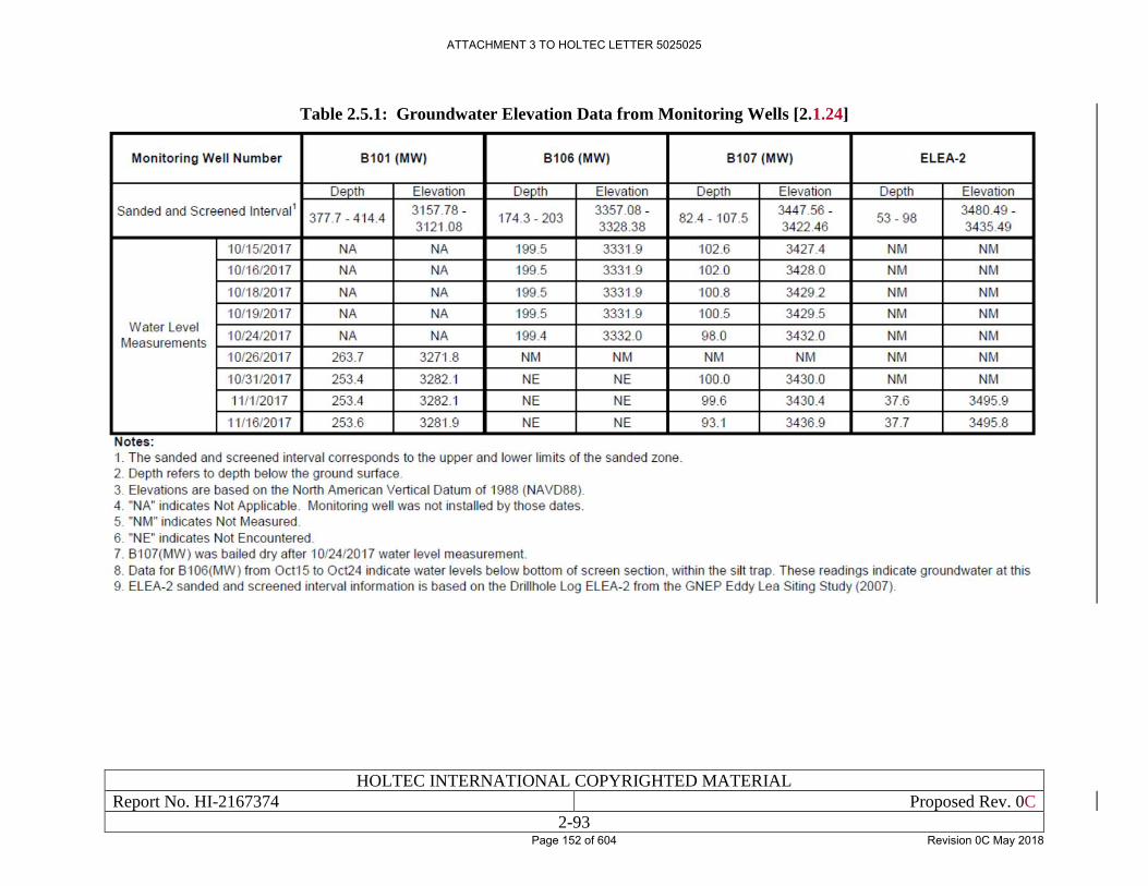
HOLTEC INTERNATIONAL COPYRIGHTED MATERIAL
Report No. HI-2167374 Proposed Rev. 0C
2-93
Table 2.5.1: Groundwater Elevation Data from Monitoring Wells [2.1.24]
ATTACHMENT 3 TO HOLTEC LETTER 5025025
Page 152 of 604 Revision 0C May 2018
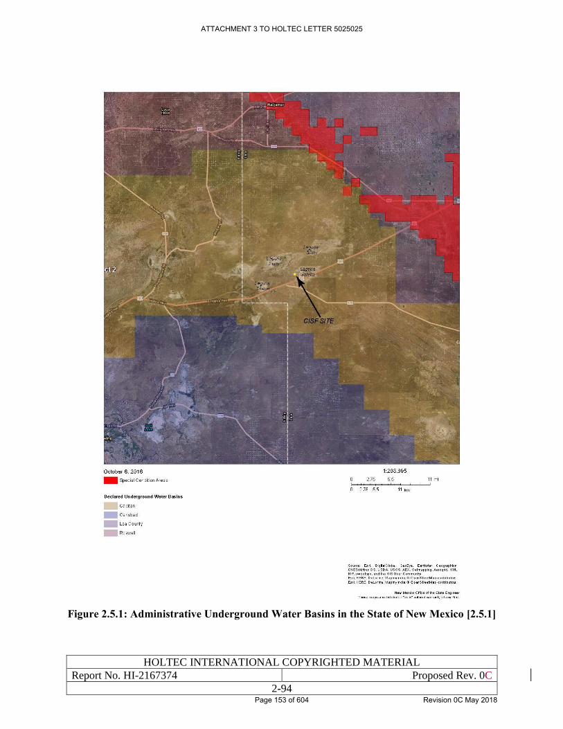
HOLTEC INTERNATIONAL COPYRIGHTED MATERIAL
Report No. HI-2167374 Proposed Rev. 0C
2-94
Figure 2.5.1: Administrative Underground Water Basins in the State of New Mexico [2.5.1]
ATTACHMENT 3 TO HOLTEC LETTER 5025025
Page 153 of 604 Revision 0C May 2018
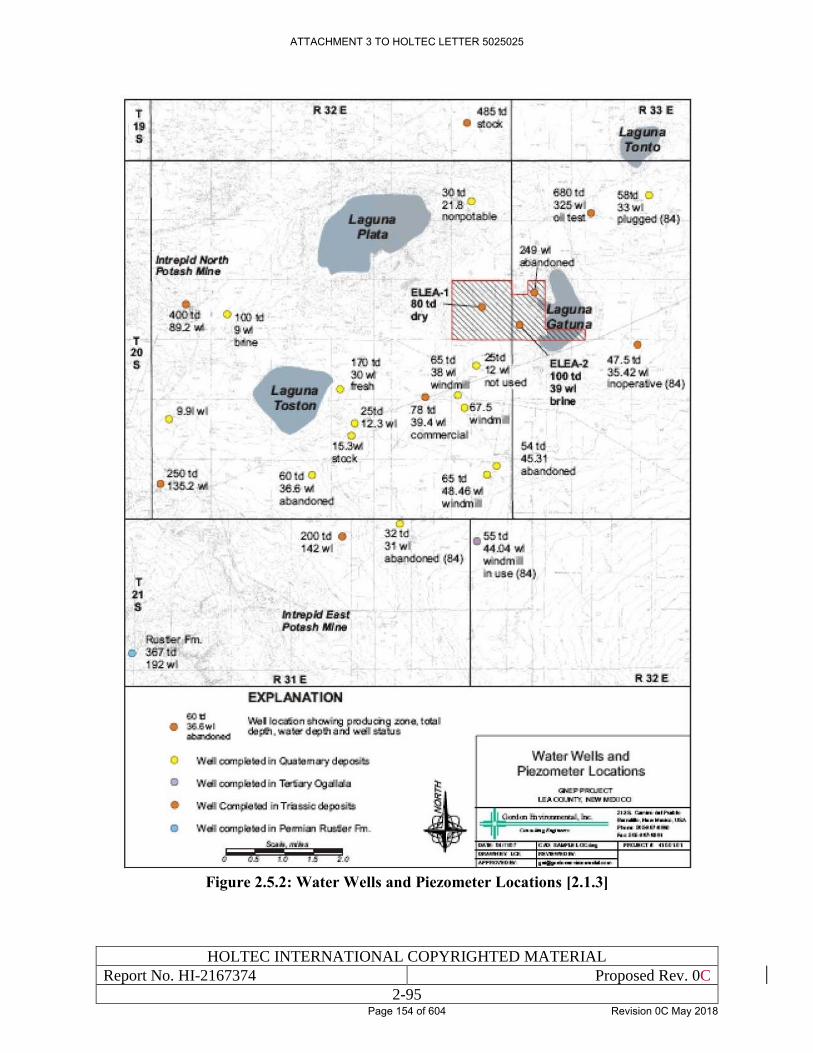
HOLTEC INTERNATIONAL COPYRIGHTED MATERIAL
Report No. HI-2167374 Proposed Rev. 0C
2-95
Figure 2.5.2: Water Wells and Piezometer Locations [2.1.3]
ATTACHMENT 3 TO HOLTEC LETTER 5025025
Page 154 of 604 Revision 0C May 2018
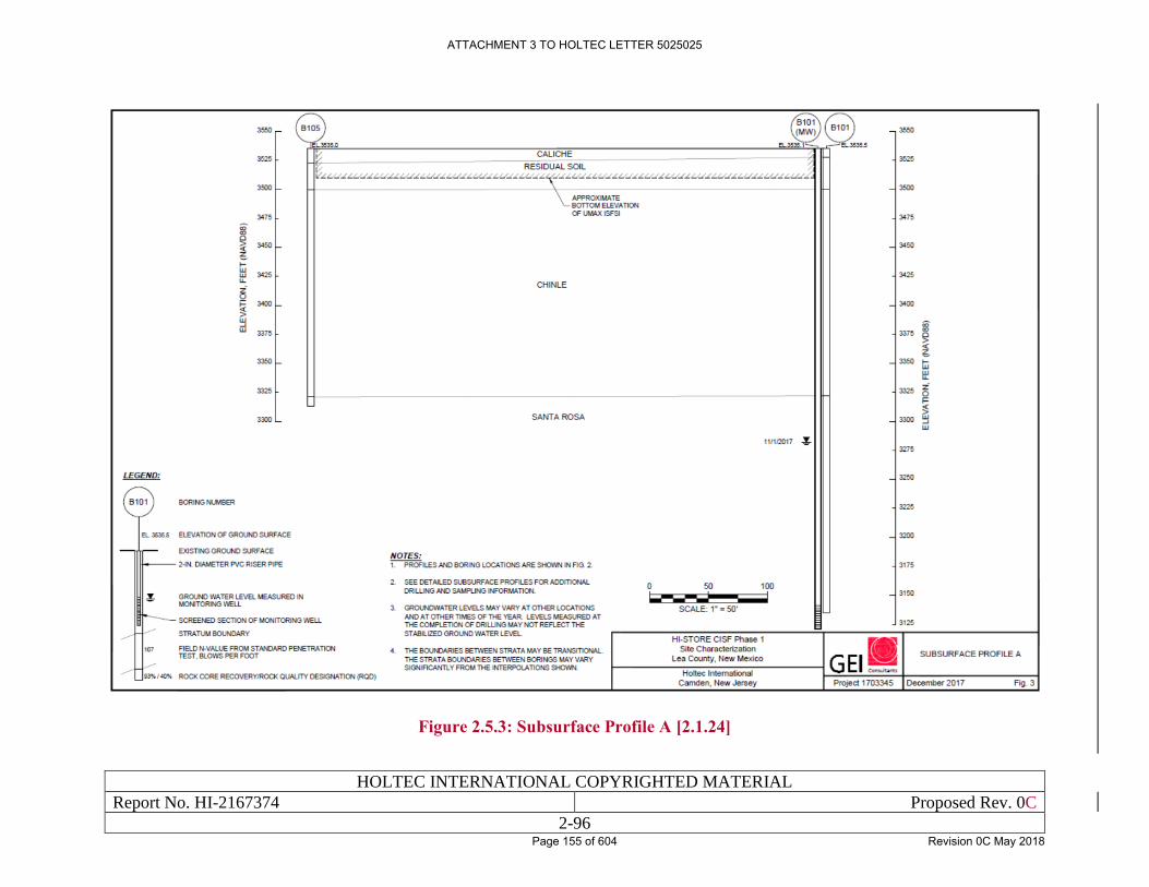
HOLTEC INTERNATIONAL COPYRIGHTED MATERIAL
Report No. HI-2167374 Proposed Rev. 0C
2-96
Figure 2.5.3: Subsurface Profile A [2.1.24]
ATTACHMENT 3 TO HOLTEC LETTER 5025025
Page 155 of 604 Revision 0C May 2018
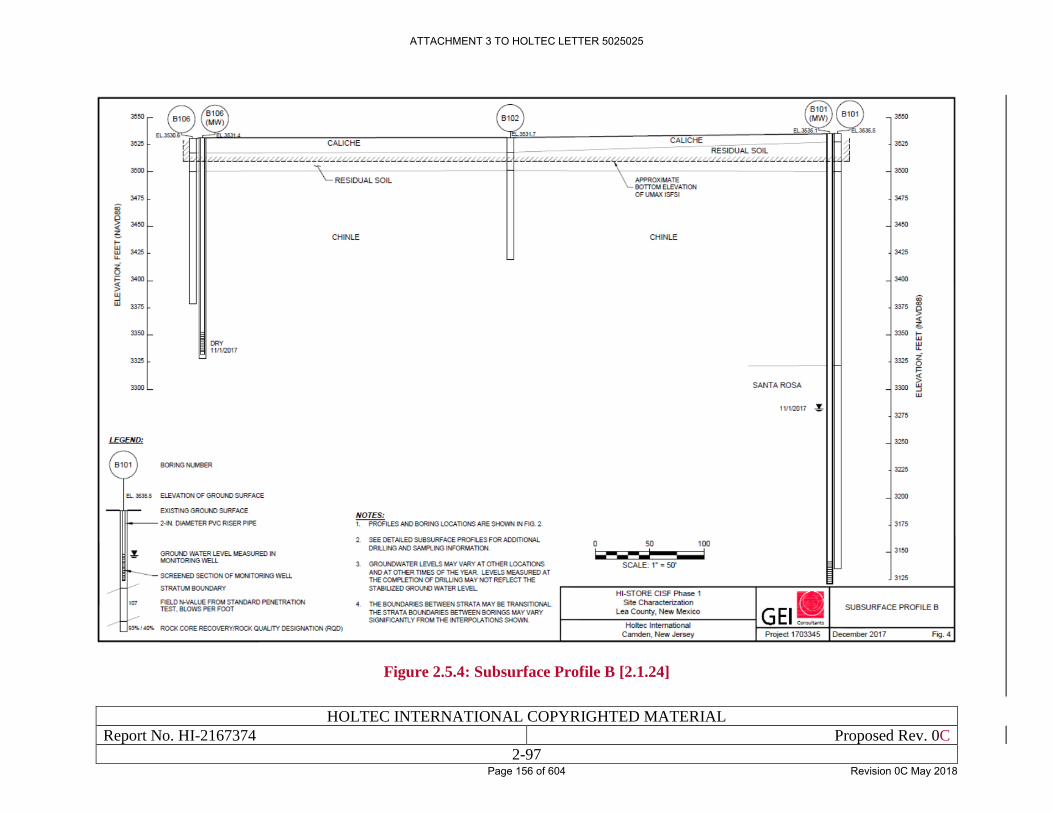
HOLTEC INTERNATIONAL COPYRIGHTED MATERIAL
Report No. HI-2167374 Proposed Rev. 0C
2-97
Figure 2.5.4: Subsurface Profile B [2.1.24]
ATTACHMENT 3 TO HOLTEC LETTER 5025025
Page 156 of 604 Revision 0C May 2018
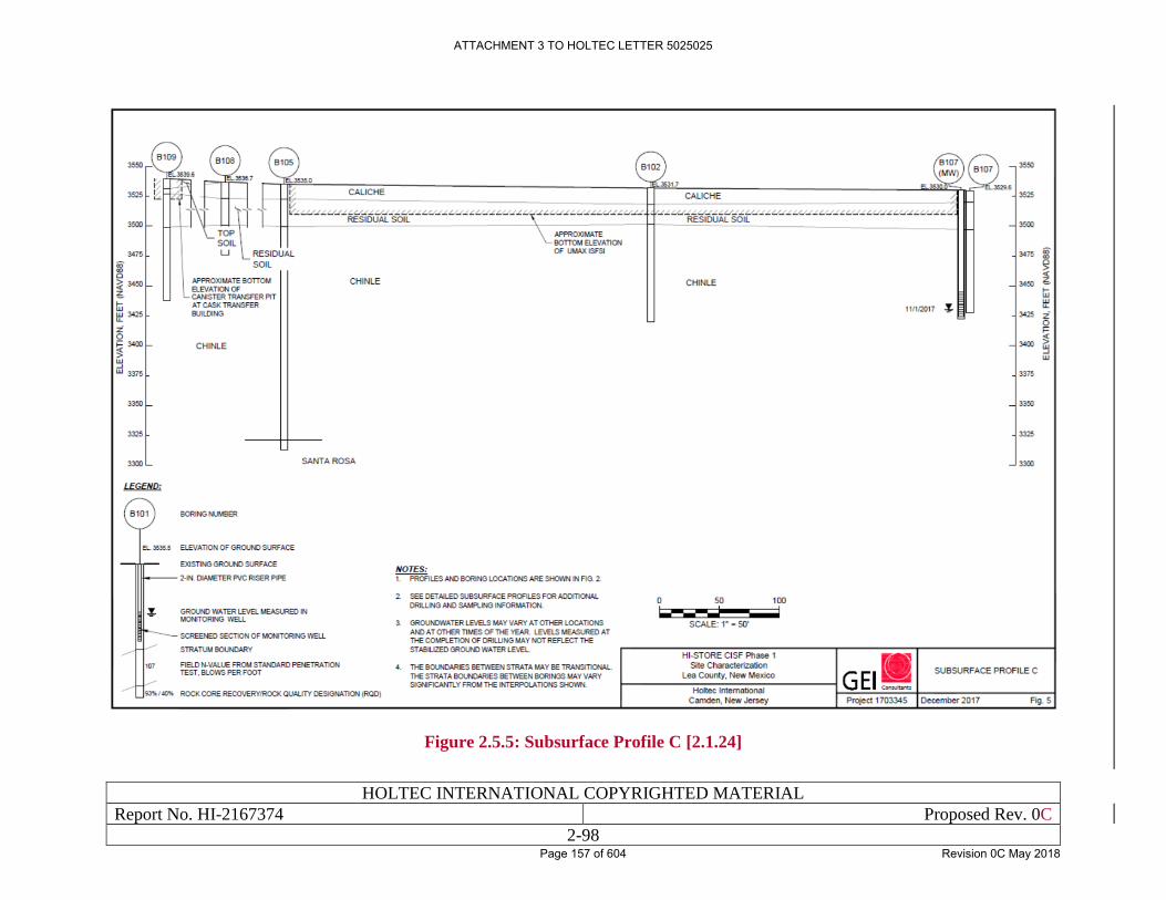
HOLTEC INTERNATIONAL COPYRIGHTED MATERIAL
Report No. HI-2167374 Proposed Rev. 0C
2-98
Figure 2.5.5: Subsurface Profile C [2.1.24]
ATTACHMENT 3 TO HOLTEC LETTER 5025025
Page 157 of 604 Revision 0C May 2018
HOLTEC INTERNATIONAL COPYRIGHTED MATERIAL
Report No. HI-2167374 Proposed Rev. 0C
2-99
2.6 GEOLOGY AND SEISMOLOGY
This section identifies the geological and seismological characteristics of the Site and its vicinity.
The location for the proposed Site, and sites in the vicinity including the WIPP (located 16 miles
southwest), and the NEF (located 38 miles southeast), have been thoroughly studied in recent years
in preparation for construction of other facilities. Data are available from these investigations in
the form of various reports [2.1.3, 2.1.24, 2.6.1, 2.6.2]. These documents and related material
provide a substantial database and description of regional and site-specific geological conditions
at the proposed Site.
2.6.1 Basic Geologic and Seismic Information
The Site is located in the northern portion of the Delaware Basin, a northerly-trending, southward
plunging asymmetrical trough with structural relief of greater than 20,000 feet on top of the
Precambrian basement rock. The Basin was formed by early Pennsylvanian time, followed by
major structural adjustment from Late Pennsylvanian to Early Permian time. During the Triassic
period, the area was uplifted, resulting in deposition of clastic continental shales (redbeds).
Continuing uplift resulted in erosion and/or nondeposition until the middle to late Cenozoic period,
when regional eastward tilting completed structural development of the basin as it exists today.
Shallow subsurface structure at the Site consists of gently east sloping beds of Triassic age redbeds,
dipping two degrees to the east. Faulting has not occurred in the northern Delaware Basin in the
area of the Site. The regional geology suggests that there have been no recent, dramatic changes
in geologic processes and rates in the vicinity of the Site [2.1.3].
During most of the Permian period, the Delaware Basin was the site of a deep marine canyon that
extended across southeastern New Mexico and west Texas. Major structural elements of the
Delaware Basin area are shown in Figure 2.6.1. The major structures of the basin include the
Guadalupe Mountains on the west side, the Central Basin Platform on the east side, and the Capitan
Reef Complex on the west and north sides of the basin. The reef created steep slopes toward the
basin and the thickness of sediments grows precipitously toward the center of the basin from the
margin of the reef. The Central Basin Platform forms an abrupt eastern terminus to the Delaware
Basin; it is a steeply fault-bound uplift of basement rocks that grew through the early and middle
Paleozoic period such that most of the pre-Permian sedimentary section is missing from its apex.
Great thickness of organic-rich marine deposits in the basin and the presence of abrupt structures
in the Capitan Reef Complex and Central Basin Platform combined to produce a prolific oil and
gas province. These areas have been the focus of intense petroleum exploration and development
activities since approximately 1920. Surficial geology and subsurface structure across the
Delaware Basin are depicted in the maps and cross section in Figures 2.6.2 through 2.6.4.
Thickness of sediments in the basin exceeds 20,000 feet, and Permian strata alone account for
more than 13,000 feet of sedimentary materials [2.1.3].
The geologic formations of concern beneath the Site comprise, from oldest to youngest, consist of
Permian-aged rocks (Wolfcamp series, Leonard series, Guadalupe series, Ochoa series); Triassic-
aged rocks (Dockum Group); and Tertiary and Quaternary rocks (Lower Gatuna Formation, Upper
Gatuna Formation); and alluvium. A stratigraphic column for the above units in provided in Figure
2.6.5.
ATTACHMENT 3 TO HOLTEC LETTER 5025025
Page 158 of 604 Revision 0C May 2018
HOLTEC INTERNATIONAL COPYRIGHTED MATERIAL
Report No. HI-2167374 Proposed Rev. 0C
2-100
The entire Site is underlain by Triassic bedrock consisting of shale, siltstone, and minor, fine-
grained, poorly sorted sandstone. Most of the proposed operational area is relatively flat and the
shale bedrock is covered by a laterally extensive veneer of 25 feet of Quaternary pediment deposits
consisting of well sorted eolian sand and sandy-gravelly materials near the bedrock interface. The
Mescalero Caliche unit is near the surface and is about 10 feet thick at the Site.
Most of the proposed operational area is relatively flat ranging from 3,520 feet above mean sea
level (AMSL) on the northern end to 3,535 feet AMSL on the southern end. The surficial geology
consists of Quaternary Pediment deposits (25 feet thick) overlying Triassic-age shale bedrock. The
different soil/geologic layers are described as follows:
• Surface Soil: sandy and well-drained (0 to 2 feet below grade);
• Mescalero Caliche: well developed, naturally cemented calcium carbonate, laterally
extensive, tightly bound and erosion resistant (2 to 12 feet below grade);
• Quaternary Sands: well sorted eolian sand and sandy-gravelly materials near the bedrock
interface (12 to 25 feet below grade);
• Dockum Group: Triassic-age, predominantly shale, siltstone, and minor, fine-grained,
poorly sorted sandstone (25 to greater than 100 feet below grade).
To determine the subsurface profile at the CIS Facility, a geotechnical survey was conducted. Nine
borings, labeled B101 through B109, were drilled throughout the area: seven at the ISFSI pad, one
along the haul path (B108), and one at the cask transfer building (B109). The location of each of
these borings can be found in Figure 2.1.8. A summary of the boring exploration data including
drilling, sampling, and field test notes, is located in Table 2.6.1. Subsurface profiles produced
based on the subsurface exploration results are located in Figures 2.5.4 through 2.5.6, with more
detailed subsurface profiles located in Figures 2.6.6 through 2.6.8. In addition, boring logs were
developed to provide details of the subsurface geology encountered during the testing process.
These boring logs can be found in Appendix C of the referenced geotechnical report [2.1.24].
Subsurface profiles were then produced based on the subsurface exploration results. These profiles
are located in Figures 2.5.4 through 2.5.6, while more detailed subsurface profiles are located in
Figures 2.6.6 through 2.6.8. In addition, boring logs were developed to provide details of the
subsurface geology encountered during the testing process. These boring logs can be found in
Appendix C in the attached GEI geotechnical rep
At the ISFSI location (B101-B107), five primary subterranean layers were observed, Figures 2.6.6
through 2.6.8:
• Top Soil layer, which consists of clayey sand with gravel on the south corners or lean clay
with sand in the center and north corners of the ISFSI site.
• Caliche layer, which consists of silty sand with gravel for all borings, along with additional
layers of narrowly graded gravel with sand and widely graded sand with silt and gravel for
the northwest and southwest corners, respectively.
• Residual layer, which consists of various layers of clayey sand and sandy lean clay at all
borings, except the northeast corner, which only included clayey sand. The center has an
additional layer of clayey sand with gravel.
ATTACHMENT 3 TO HOLTEC LETTER 5025025
Page 159 of 604 Revision 0C May 2018
HOLTEC INTERNATIONAL COPYRIGHTED MATERIAL
Report No. HI-2167374 Proposed Rev. 0C
2-101
• Chinle layer, which consists of various layers of lean clay, sandy lean clay, lean clay with
sand, and clayey sand. Mudstone was encountered at this layer for all borings.
• Santa Rosa layer, which consists of various layers of mudstone and sandstone. Only
borings B101 and B105 at the southern corners encountered this layer.
These borings describe the subgrade and under-grade space makeup of Spaces B, C, and D beneath
the ISFSI pad in Figure 4.3.1.
At the haul path (B108), four primary subterranean layers were tested:
• Top Soil layer which consists of clayey sand.
• Caliche layer which consists of silty sand with gravel.
• Residual layer which consists of various layers of clayey sand, sandy lean clay, and clayey
sand with gravel.
• Chinle layer which consists of various layers of lean clay with sand, and then sandy lean
clay before the end of boring.
At the CTF site (B109), four primary subterranean layers were tested:
• Top Soil layer which consists of lean clay with sand and sandy lean clay with gravel.
• Caliche layer which consists of clayey sand and sandy lean clay layers.
• Residual layer which consists of various layers of sandy lean clay, clayey sand, and lean
clay with sand.
• Chinle layer which consists of various layers of lean clay, sandy lean clay, lean clay with
sand, and clayey sand. Mudstone was encountered at this layer.
Soil properties, such as grain size, specific gravity, density, Atterberg limits, shear velocity, and
water content were determined and are tabulated in Tables 2.6.2 through 2.6.4. The graphical
Atterberg limit results and shear wave velocities are shown in Figures 2.6.9 and 2.6.10,
respectively. All of the testing deliverables are defined in the geotechnical report [2.1.24] and are
summarized in Tables 2.6.2 and 2.6.3 below. Table 2.6.5 provides locations of applicable data in
the geotechnical report [2.1.24].
The Top Soil layer ranges from 3 to 4 inches deep, but was 8.1 feet thick at the CTF. The soil
consists of varying loose-to-medium dense amounts of sand and clay. Next, the Mescalero Caliche
layer ranges from 4.4 to 13.5 feet thick. The soil consists of varying dense-to-very dense amounts
of sand and gravel with silt, with unit weights between 84.5 to 94.2 pounds per cubic foot. Finally,
the Residual Soil layer ranges from 17 to 28 feet thick. The soil consists of varying very hard or
very dense amounts of clayey sand or sandy clay with traces of gravel, with unit weights between
98.6 to 126.4 pounds per cubic foot [2.1.24].
The Chinle Formation layer is the first bedrock layer encountered, from a depth of 27.5 to 40.5
feet. The rock consists of varying layers of lean clay or clayey sand, classified from the SPT N-
values as very dense soil to soft rock. Lastly, the Santa Rosa Formation is the last tested bedrock
layer, where samples were collected at depths of 401 and 222 feet from two separate borings. The
rock consists of varying ranges of fine-to-coarse grained sandstone, with minor reddish-brown
ATTACHMENT 3 TO HOLTEC LETTER 5025025
Page 160 of 604 Revision 0C May 2018
HOLTEC INTERNATIONAL COPYRIGHTED MATERIAL
Report No. HI-2167374 Proposed Rev. 0C
2-102
siltstones and conglomerate. Details of the soil and rock layers are included in Section 5.2 of the
geotechnical report [2.1.24].
Monitoring wells were drilled next to borings B101, B106, and B107 to determine the groundwater
elevation at the ISFSI site. Laboratory testing was conducted on the soil and rock extracted from
these borings. As stated in Section 2.5, the primary groundwater table is at 253-263 feet below
grade. Excavation to a depth of 25 feet below grade is expected for facility construction; thus, the
construction activity will not be in contact with the groundwater table.
2.6.2 Vibratory Ground Motion
Earthquakes of low to moderate magnitude have been documented within a 200 mile radius of the
Site. The vast majority of the earthquake activity is located southeast of the Site in west Texas,
and west/northwest of the Site in central New Mexico. The U.S. Geological Survey (USGS)
earthquake database was used to query historical earthquakes within a 200 mile radius of the Site
[2.6.3]. Results of the search of the 200 mile radius yielded a total of 244 historical earthquakes
with magnitude 2.5 or greater between 1900 and the most recent update of the database in 2016.
The results indicate the closest earthquake to the Site was 24 miles southwest with a magnitude of
3.1 that occurred on March 18, 2012. Two earthquakes with magnitudes greater than 5.0 were
recorded within 200 miles of the Site. An earthquake with magnitude 6.5 occurred on August 16,
1931, located 140 miles southwest of the Site; and an earthquake with magnitude 5.7 occurred on
April 14, 1995, located 165 miles south of the Site. The Eunice earthquake of January 2, 1992,
located 39 miles east of the Site had a magnitude of 4.6. The results of the USGS earthquake search
are plotted on a regional map in Figure 2.6.11.
There are three seismic source zones within a 200 mile radius of the Site: the northern and southern
regions of the Southern Basin and Range – Rio Grande rift zone located west and southwest of the
Site; and the Central Basin Platform zone located east of the Site. The most active seismic area
within 200 miles of Site is the Central Basin Platform east of the Site. Large magnitude earthquakes
are not occurring or have not occurred within the recent geologic past along the Central Basin
platform due to the absence of Quaternary faults. The seismicity in west Texas, southeast of the
Site, is hypothesized as being a result of fluid pressure build-up from fluid injection, and
consequential reduction in effective stress across pre-existing fractures and associated decrease in
frictional resistance to sliding. Similarly, recent records (1998 through 2005) from the WIPP
seismic monitoring network indicate that the strongest events recorded annually in 1999, 2000,
and 2002 through 2005 (typically of 2.5 to 4.0 magnitude during this time period) have been
located about 50 miles west of the Site. This seismic activity is suspected to be induced by injection
of waste water from natural gas production into deep well or wells [2.1.3].
A review of the seismic risk was based on USGS Geologic Hazards Science Center’s 2009
Earthquake Probability Mapping [2.6.4], which generates maps that show the probability of a
magnitude 5.0 or higher earthquake within a 30-mile radius of any location within the next 50
years. On a scale of 0.00 (the lowest probability of earthquake) to 1.00 (the highest probability),
all Project facilities are within the low probability range of 0.01 to 0.02 as shown in Figure 2.6.12.
Earthquake probability is dominated by seismic activity within the Central Basin Platform south
and east of the Site.
Probabilistic ground motion for the Site was determined using information from the USGS [2.6.5].
Figure 2.6.13 is a probabilistic ground motion map of the Site, illustrating peak horizontal
ATTACHMENT 3 TO HOLTEC LETTER 5025025
Page 161 of 604 Revision 0C May 2018
HOLTEC INTERNATIONAL COPYRIGHTED MATERIAL
Report No. HI-2167374 Proposed Rev. 0C
2-103
acceleration with a 2 percent probability of exceedance in 50 years (2,500 year return interval).
The Peak Horizontal Ground Acceleration (PGA) value of 0.04 of the acceleration due to gravity
(g) to 0.06g estimated by the regional USGS algorithm is similar to values suggested by several
site-specific studies for nearby locations. The Geological Characterization Report (GCR) for the
WIPP Site [2.6.1] determined acceleration of ≤0.06g for a return interval of 1,000 years, and ≤0.1g
for a return interval of 10,000 years (WIPP is located approximately 16 miles southwest of the
Site); the results of the GCR were reviewed and confirmed by Sanford et al. [2.6.5]), which
estimated a maximum expected acceleration of 0.1g for the WIPP, and again in the Safety
Evaluation Report for the WIPP [2.6.6], which describes the GCR results as conservative. The
seismic hazard for the National Enrichment Facility (NEF) uranium enrichment facility predicts
0.15g for a return interval of 10,000 years [2.6.2]. The NEF facility is about 38 miles southeast of
the Site [2.1.3].
Quaternary-age faulting (exhibiting movement in the past 1.6 million years) is not present in the
vicinity of the Site. The nearest Quaternary-age fault is located 85 miles southwest of the Site
[2.6.7]. Little is known about this fault except that it is a normal fault, 3.6 miles in length, and has
a slip rate of less than 0.01 in/yr. The Guadalupe fault forms a scarp on unconsolidated Quaternary
deposits at the western base of the Guadalupe Mountains in the Basin and Range physiographic
province. The same USGS database shows numerous other Quaternary-age faults within a 200-
mile radius of the Site, located to the west and southwest, most of which are at the distal end of
the radius and are near the Rio Grande Rift of central New Mexico. Figure 2.6.14 is a map of New
Mexico and West Texas showing Quaternary-age faulting as cataloged by the USGS, and as down-
loaded from the database referenced above. The database contains locations and information on
faults and associated folds that have been active during the Quaternary.
In all, there are a total of 27 Quaternary faults or fault zones within a 200-mile radius of the Site.
A total of four “capable” faults were identified, the closest being the Guadalupe fault (85 miles to
the southwest). A “capable” fault is one that has exhibited one or more of the following
characteristics (10 CFR 100 [2.6.10] Appendix A.III, Definitions):
• Movement at or near the ground surface at least once within the past 35,000 years or
movement of a recurring nature within the past 500,000 years.
• Macro-seismicity instrumentally determined with records of sufficient precision to
demonstrate a direct relationship with the fault.
• A structural relationship to a capable fault according to the previous two characteristics
such that movement on one could be reasonably expected to be accompanied by movement
on the other.
For the purposes of this assessment, capable faults were identified based solely upon the first
characteristic above.
2.6.3 Surface Faulting
There are no surface faults at the Site. Tectonic activity in the Delaware Basin is characterized by
slow uplift relative to surrounding areas which has resulted in erosion and dissolution of rocks in
the Basin. Faulting has not occurred in the northern Delaware Basin in the area of the Site. The
regional geology suggests that there have been no recent, dramatic changes in geologic processes
and rates in the vicinity of the Site [2.1.3].
ATTACHMENT 3 TO HOLTEC LETTER 5025025
Page 162 of 604 Revision 0C May 2018
HOLTEC INTERNATIONAL COPYRIGHTED MATERIAL
Report No. HI-2167374 Proposed Rev. 0C
2-104
2.6.4 Stability of Subsurface Materials
The entire Site is underlain by Triassic bedrock consisting of shale, siltstone, and minor, fine-
grained, poorly sorted sandstone. Most of the proposed operational area is relatively flat and the
shale bedrock is covered by a laterally extensive veneer of 25 feet of Quaternary pediment deposits
consisting of well sorted eolian sand and sandy-gravelly materials near the bedrock interface. The
Mescalero Caliche unit is near the surface and is about 10 feet thick at the Site.
Comparison of conditions at the Site with those conditions favorable to karst development
indicates that conditions at the Site are not conducive to karst development. No thick sections of
soluble rock are present at or near land surface; the shallowest soluble bedrock materials are
gypsum and halite beds in the Rustler Formation, which is located at least 1,100 feet below land
surface at the Site. Additionally, rainfall rates in the area are low. Mescalero caliche is soluble and
situated at or near land surface; however this unit is no more than 10 feet in thickness. Local
dissolution of this unit may have resulted in the development of a number of small shallow
depressions in the area; however this is not regarded as an active or significant karst process at the
Site [2.1.3].
During site reconnaissance, detailed inspection of the areas around the margins of Laguna Gatuna
and tributary drainages was performed to identify any tension cracks, disrupted soils, tilting, or
other evidence of rapid earth displacement. No tension cracks or other evidence of displacement
was observed. Additionally, older cultural features in the area were inspected to identify evidence
of tilting, offset, or displacement that could indicate recent land movement. A number of oil wells
were drilled along the west flank of Laguna Gatuna beginning in the early 1940’s. Most of the
wells were abandoned by 1975 and well monuments were installed; several of the well monuments
were identified during site reconnaissance. None of the monuments displayed evidence of tilting
that might be associated with local earth movements [2.1.3].
A halite preservation and stability assessment entitled, Report on Evaporite Stability in the Vicinity
of the Proposed GNEP Site, Lea County, NM was performed for the Site as part of the GNEP siting
study [2.1.3]. This study was conducted in order assess existing data on the continuity and stability
of evaporites under the Site, with special attention to data within, or adjacent to the boundaries of
nearby lakes or playas. The main data sources for the project area include potash exploration
drillholes and oil and gas drillholes.
Lithologic logs from potash exploration and geophysical logs from oil and gas exploration around
the Site in southwestern Lea County, New Mexico, provide evidence of the extent and stability of
evaporites and their possible relationship to the formation of playas in the vicinity.
An elevation map on the uppermost evaporite-bearing bed (top of Permian Rustler Formation)
shows continuity across the area. General northeast slopes are revealed, with some flattened slopes
associated with Laguna Plata. There are no indications of lowering of the surface by dissolution;
the top of Rustler under most of Laguna Plata is actually elevated above the general trend. The
surface varies locally due to variable reporting for potash drillholes of the first encounter with the
uppermost sulfate bed of the Rustler.
There are no surface, drillhole, or mining indications that subsidence and collapse chimneys occur
at the Site or surrounding area. These features are associated with the front of the Capitan reef,
which is south of the Site, and with a hydraulic environment that is not known to exist at the Site.
ATTACHMENT 3 TO HOLTEC LETTER 5025025
Page 163 of 604 Revision 0C May 2018
HOLTEC INTERNATIONAL COPYRIGHTED MATERIAL
Report No. HI-2167374 Proposed Rev. 0C
2-105
Geophysical logs indicate that halite in the Rustler persists across the Site area. Dissolution from
above to create lows on the uppermost Rustler is not a practical process. There is neither subsurface
drillhole data nor surface features indicating a dissolution front in the vicinity of the Site. There is
no evidence for either past or continuing natural processes that would cause Site instability due to
halite dissolution in the near future [2.1.3].
With regard to potential future drilling on the Site, Holtec has an agreement [2.6.9] with Intrepid
Mining LLC (Intrepid) such that Holtec controls the mineral rights on the Site and Intrepid will
not conduct any potash mining on the Site. Additionally, any future oil drilling or fracking beneath
the Site would occur at greater than 5,000 feet depth, which ensures there would be no subsidence
concerns [2.1.8].
Based on the data from the borings and analyses, the soils at the site are not susceptible to
liquefaction. The soils encountered at the site were evaluated for liquefaction potential using the
methods described in Youd, et al., 2001 [2.6.12] as prescribed by Regulatory Guide 1.198 [2.6.11].
Corrected N-values greater than 30 blows per foot are too dense to liquefy in an earthquake of any
size, and are therefore classified as non-liquefiable. In addition, soils above the groundwater table
are not susceptible to liquefaction [2.6.12].
2.6.5 Slope Stability
The site terrain ranges in elevation from 3,520 to 3,540 feet above mean sea-level sloping gently
downward from south to north. Most of the site is flat with slopes ranging from 0 to 3 percent, as
shown in Figure 2.6.15. Therefore, there is no risk from slope instability (i.e. landslides) in the
vicinity of the Site.
2.6.6 Construction Excavation
During the construction of Phase 1 of the HI-STORE CISF, there will be multiple areas where
excavation will be required to accommodate and install the underground facilities; specifically, the
Canister Transfer Facilities (CTF) which are located in the Cask Transfer Building (CTB), and the
UMAX field. In both cases, the expected total excavation depth is approximately twenty-five (25)
feet.
According to the geotechnical borings, there are two layers of subsurface material that will be
encountered during construction excavations. The native caliche layer, which is approximately 12
feet in depth from top of existing grade, and the native residual soil layer, which makes up
approximately 13 feet of depth for the remaining required excavation depth for site facilities. In
no instance is it expected that construction excavations will encounter the native Chinle layer.
In order to accommodate construction vehicle access and industry wide safety standards, it is
expected that construction practices will utilize a minimum 1:1 slope around the extents of the
excavation pits. This method will create ~124,000 cubic yards (CY) of caliche spoils and ~121,500
CY of residual soil spoils; some of which (~24,000 CY) will be utilized to backfill the excavation
area. It should be noted that the residual soil layer will be utilized for the backfill material as it
meets the minimum density and shear wave velocity requirements that are required for Space B,
referenced in Figure 4.3.1.
Once the areas have been excavated, the supporting soil will be prepared to receive the reinforced
concrete Support Foundation Pad (SFP). The residual soil surfaces shall be proof rolled by a heavy
vibrating compactor, prior to the placement of compacted fill or foundations. Careful observation
ATTACHMENT 3 TO HOLTEC LETTER 5025025
Page 164 of 604 Revision 0C May 2018
HOLTEC INTERNATIONAL COPYRIGHTED MATERIAL
Report No. HI-2167374 Proposed Rev. 0C
2-106
shall be made by a professional engineer licensed in New Mexico or their approved representative
during proof rolling in order to identify any areas of soft, yielding soils that may require over-
excavation and replacement. Once the subsurface has been prepared and compacted, the
supporting residual soil fill (Space C) shall be confirmed to have reached a compaction of 95
percent (minimum) of the modified Proctor maximum dry density (in accordance with ASTM
D1557). The compaction should be conducted at or close to the optimum moisture content
indicated by the modified Proctor test procedure (ASTM D1557).
Upon completion of subgrade preparation/compaction, placement of the reinforced concrete
Support Foundation Pad (SFP) and UMAX Cavity Enclosure Containers (CECs), backfilling of
Spaces A and B (Figure 4.3.1) will commence. Space A will consist of a Controlled Low Strength
Material (CLSM) or lean concrete that has a minimum compressive strength and density of 1,000
psi and 120 pcf, respectively, as referenced in Table 4.3.3. Since the backfilling process is
iterative, as the fill materials are brought back up to finished grade, the sloped areas of the
excavation pit that make up Space B of the UMAX lateral subgrade, will be composed of the
aforementioned residual soil. Again, it is expected that for Phase 1 of the HI-STORE CISF, and
all subsequent phases, ~24,000 CY of this residual soil will be required to fill out the Space B
portion of the excavated area.
ATTACHMENT 3 TO HOLTEC LETTER 5025025
Page 165 of 604 Revision 0C May 2018
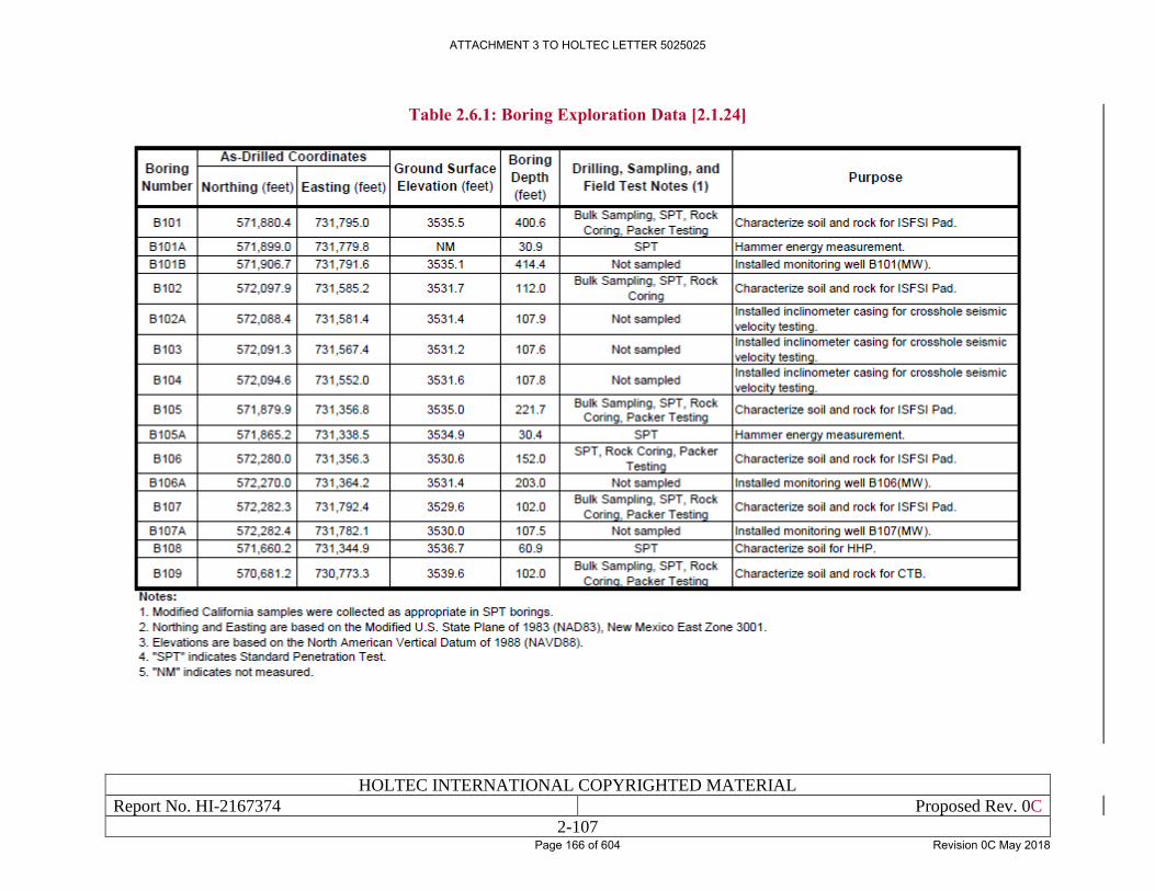
HOLTEC INTERNATIONAL COPYRIGHTED MATERIAL
Report No. HI-2167374 Proposed Rev. 0C
2-107
Table 2.6.1: Boring Exploration Data [2.1.24]
ATTACHMENT 3 TO HOLTEC LETTER 5025025
Page 166 of 604 Revision 0C May 2018
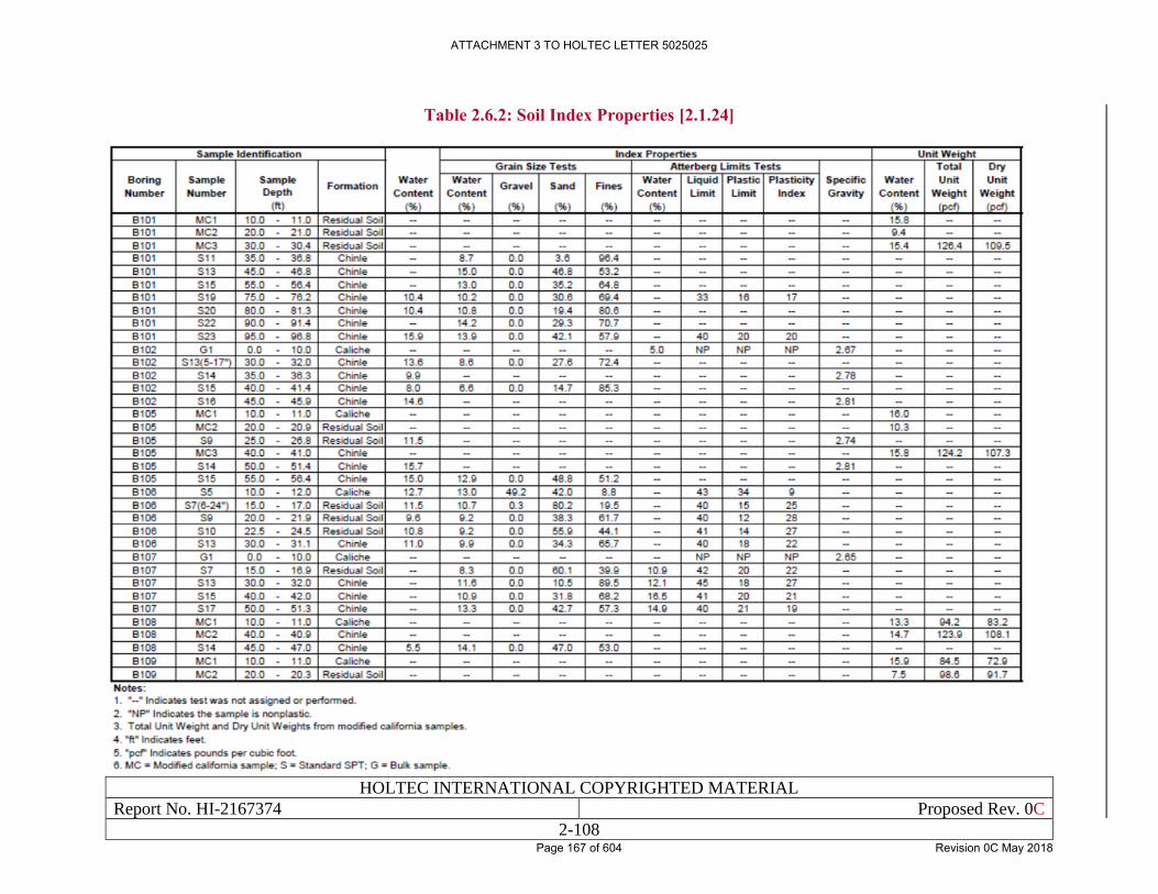
HOLTEC INTERNATIONAL COPYRIGHTED MATERIAL
Report No. HI-2167374 Proposed Rev. 0C
2-108
Table 2.6.2: Soil Index Properties [2.1.24]
ATTACHMENT 3 TO HOLTEC LETTER 5025025
Page 167 of 604 Revision 0C May 2018
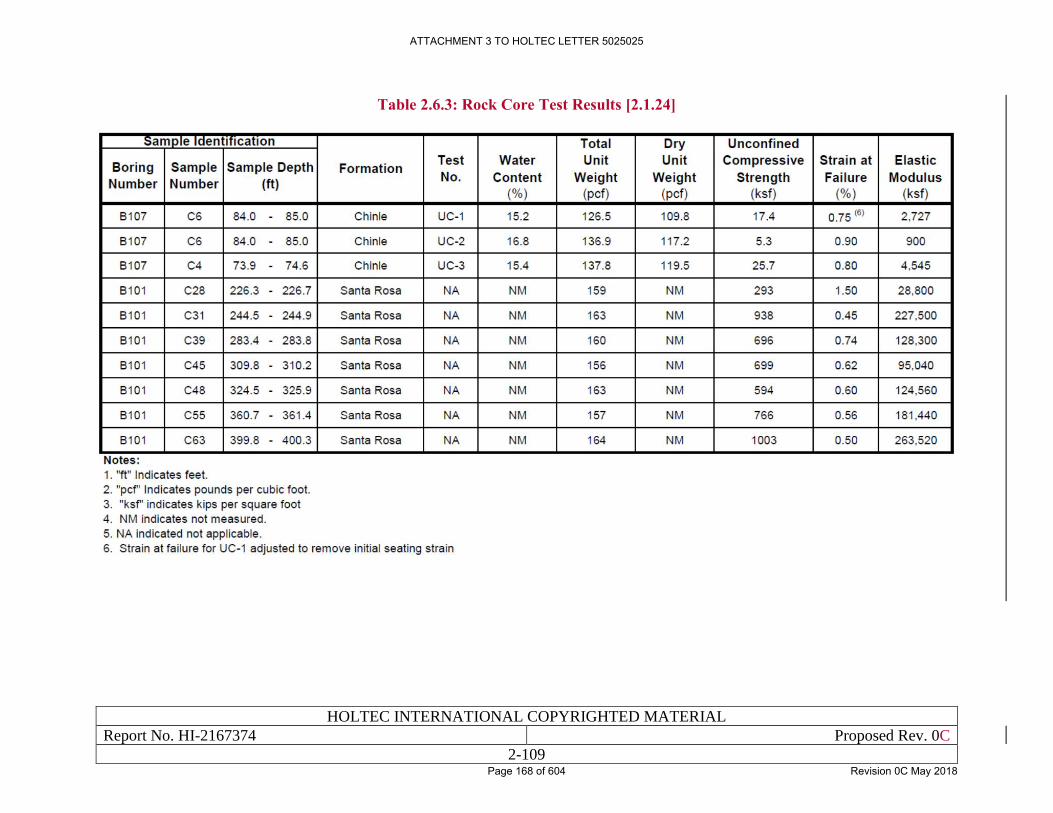
HOLTEC INTERNATIONAL COPYRIGHTED MATERIAL
Report No. HI-2167374 Proposed Rev. 0C
2-109
Table 2.6.3: Rock Core Test Results [2.1.24]
ATTACHMENT 3 TO HOLTEC LETTER 5025025
Page 168 of 604 Revision 0C May 2018
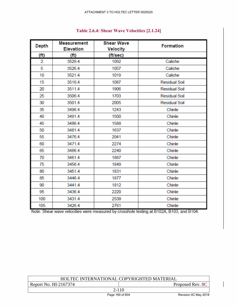
HOLTEC INTERNATIONAL COPYRIGHTED MATERIAL
Report No. HI-2167374 Proposed Rev. 0C
2-110
Table 2.6.4: Shear Wave Velocities [2.1.24]
ATTACHMENT 3 TO HOLTEC LETTER 5025025
Page 169 of 604 Revision 0C May 2018
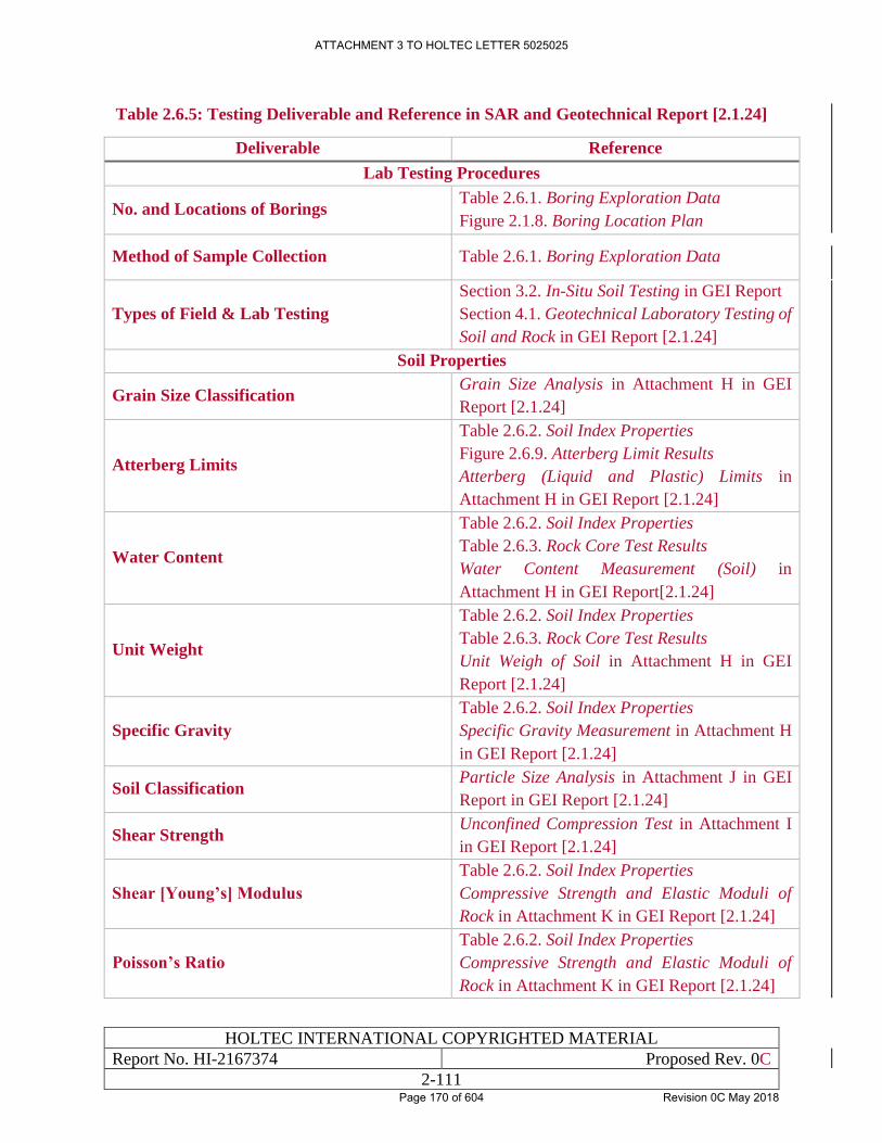
HOLTEC INTERNATIONAL COPYRIGHTED MATERIAL
Report No. HI-2167374 Proposed Rev. 0C
2-111
Table 2.6.5: Testing Deliverable and Reference in SAR and Geotechnical Report [2.1.24]
Deliverable Reference
Lab Testing Procedures
No. and Locations of Borings Table 2.6.1. Boring Exploration Data
Figure 2.1.8. Boring Location Plan
Method of Sample Collection Table 2.6.1. Boring Exploration Data
Types of Field & Lab Testing
Section 3.2. In-Situ Soil Testing in GEI Report
Section 4.1. Geotechnical Laboratory Testing of
Soil and Rock in GEI Report [2.1.24]
Soil Properties
Grain Size Classification Grain Size Analysis in Attachment H in GEI
Report [2.1.24]
Atterberg Limits
Table 2.6.2. Soil Index Properties
Figure 2.6.9. Atterberg Limit Results
Atterberg (Liquid and Plastic) Limits in
Attachment H in GEI Report [2.1.24]
Water Content
Table 2.6.2. Soil Index Properties
Table 2.6.3. Rock Core Test Results
Water Content Measurement (Soil) in
Attachment H in GEI Report[2.1.24]
Unit Weight
Table 2.6.2. Soil Index Properties
Table 2.6.3. Rock Core Test Results
Unit Weigh of Soil in Attachment H in GEI
Report [2.1.24]
Specific Gravity
Table 2.6.2. Soil Index Properties
Specific Gravity Measurement in Attachment H
in GEI Report [2.1.24]
Soil Classification Particle Size Analysis in Attachment J in GEI
Report in GEI Report [2.1.24]
Shear Strength Unconfined Compression Test in Attachment I
in GEI Report [2.1.24]
Shear [Young’s] Modulus
Table 2.6.2. Soil Index Properties
Compressive Strength and Elastic Moduli of
Rock in Attachment K in GEI Report [2.1.24]
Poisson’s Ratio
Table 2.6.2. Soil Index Properties
Compressive Strength and Elastic Moduli of
Rock in Attachment K in GEI Report [2.1.24]
ATTACHMENT 3 TO HOLTEC LETTER 5025025
Page 170 of 604 Revision 0C May 2018
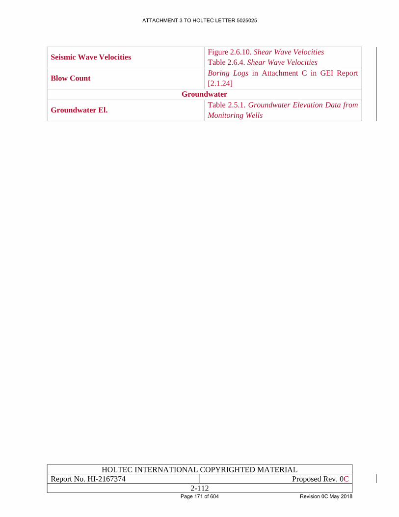
HOLTEC INTERNATIONAL COPYRIGHTED MATERIAL
Report No. HI-2167374 Proposed Rev. 0C
2-112
Seismic Wave Velocities Figure 2.6.10. Shear Wave Velocities
Table 2.6.4. Shear Wave Velocities
Blow Count Boring Logs in Attachment C in GEI Report
[2.1.24]
Groundwater
Groundwater El. Table 2.5.1. Groundwater Elevation Data from
Monitoring Wells
ATTACHMENT 3 TO HOLTEC LETTER 5025025
Page 171 of 604 Revision 0C May 2018

HOLTEC INTERNATIONAL COPYRIGHTED MATERIAL
Report No. HI-2167374 Proposed Rev. 0C
2-113
Figure 2.6.1: Major Regional Geological Structures near the Site [2.1.3]
ATTACHMENT 3 TO HOLTEC LETTER 5025025
Page 172 of 604 Revision 0C May 2018
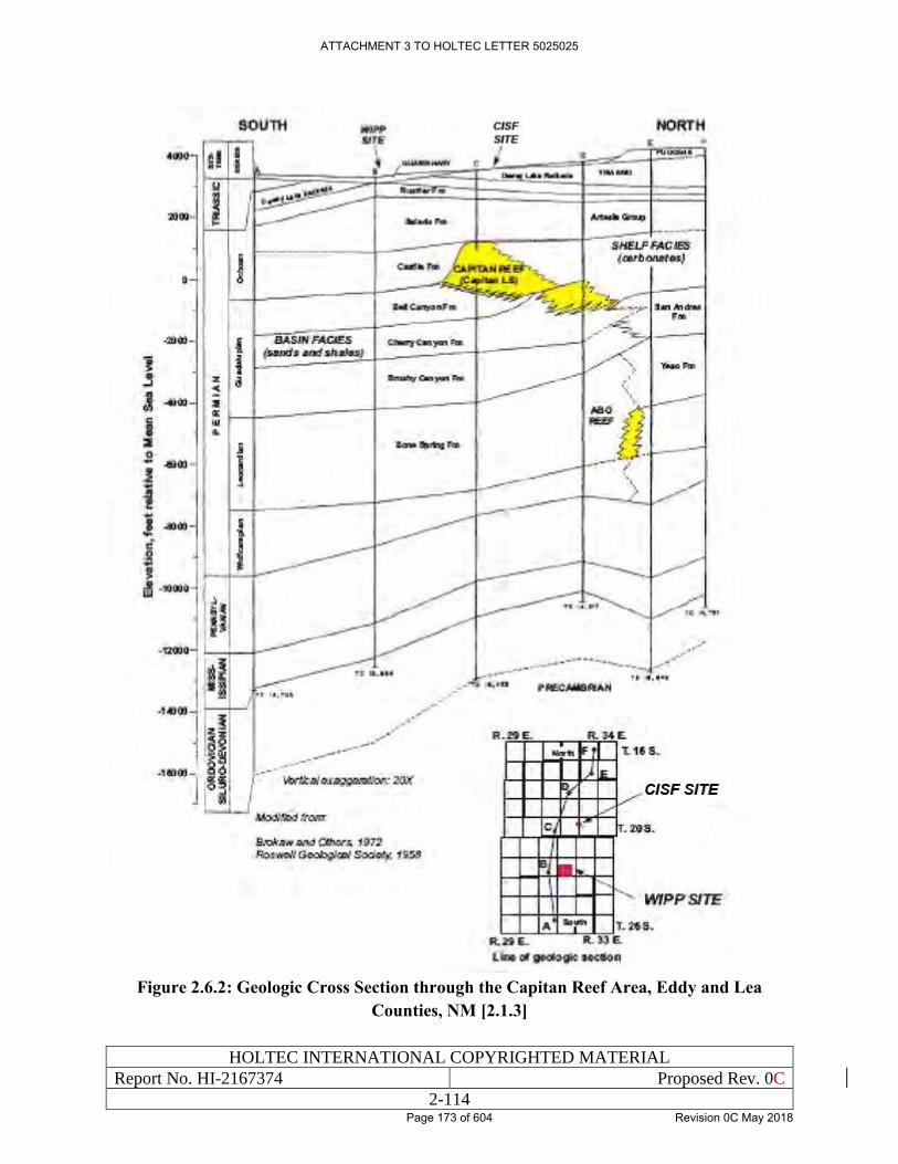
HOLTEC INTERNATIONAL COPYRIGHTED MATERIAL
Report No. HI-2167374 Proposed Rev. 0C
2-114
Figure 2.6.2: Geologic Cross Section through the Capitan Reef Area, Eddy and Lea
Counties, NM [2.1.3]
ATTACHMENT 3 TO HOLTEC LETTER 5025025
Page 173 of 604 Revision 0C May 2018
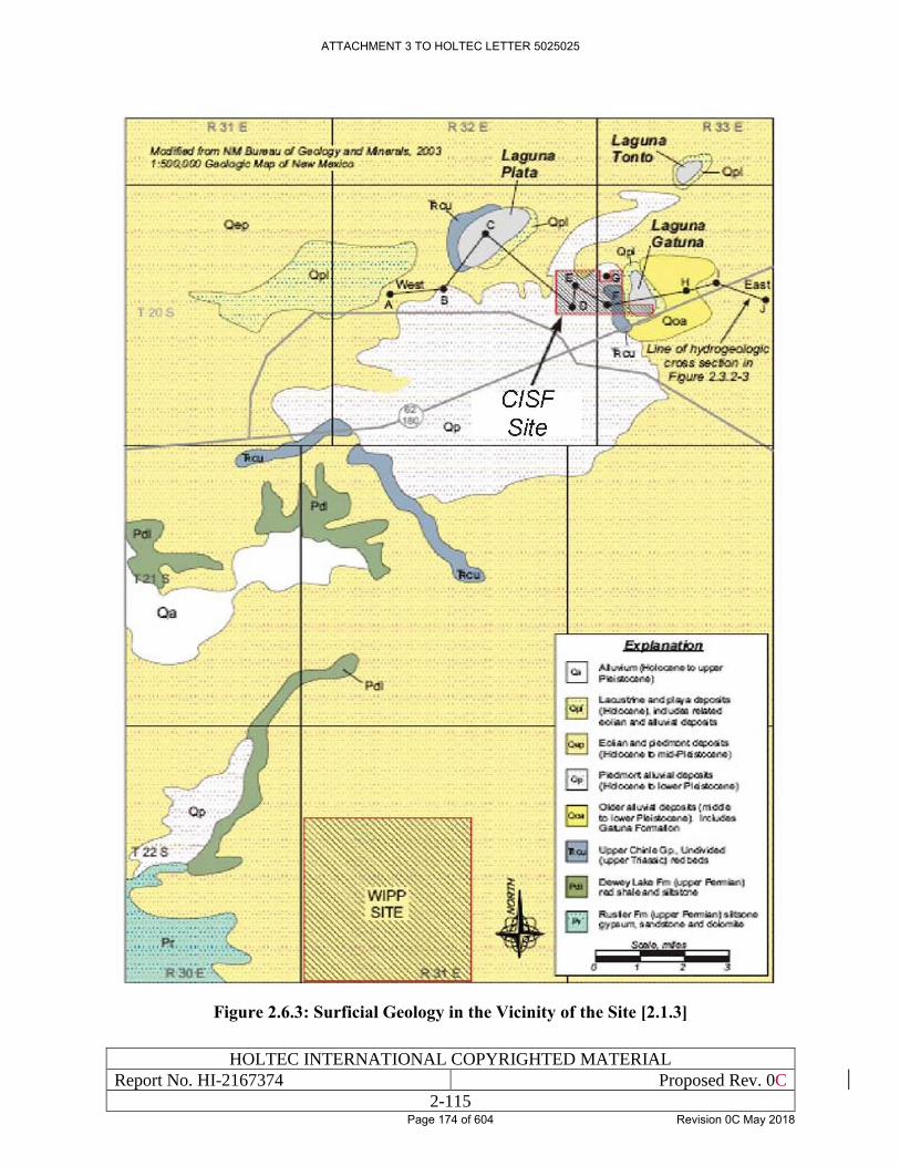
HOLTEC INTERNATIONAL COPYRIGHTED MATERIAL
Report No. HI-2167374 Proposed Rev. 0C
2-115
Figure 2.6.3: Surficial Geology in the Vicinity of the Site [2.1.3]
ATTACHMENT 3 TO HOLTEC LETTER 5025025
Page 174 of 604 Revision 0C May 2018
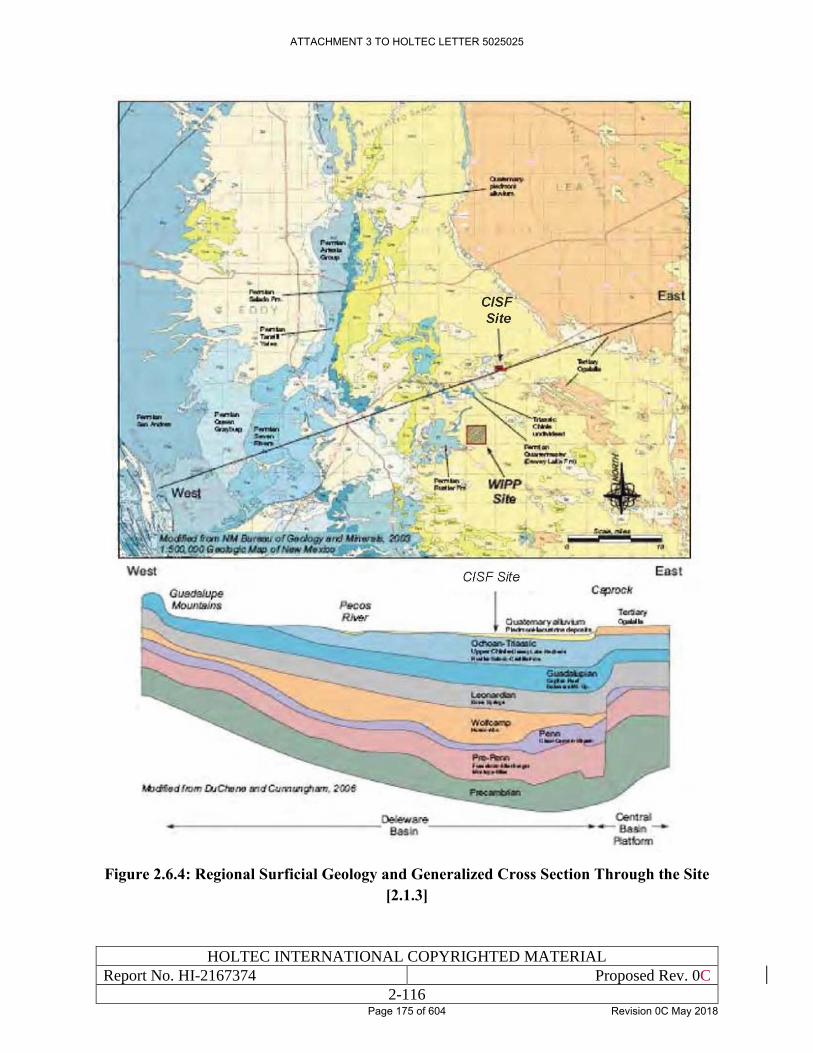
HOLTEC INTERNATIONAL COPYRIGHTED MATERIAL
Report No. HI-2167374 Proposed Rev. 0C
2-116
Figure 2.6.4: Regional Surficial Geology and Generalized Cross Section Through the Site
[2.1.3]
ATTACHMENT 3 TO HOLTEC LETTER 5025025
Page 175 of 604 Revision 0C May 2018
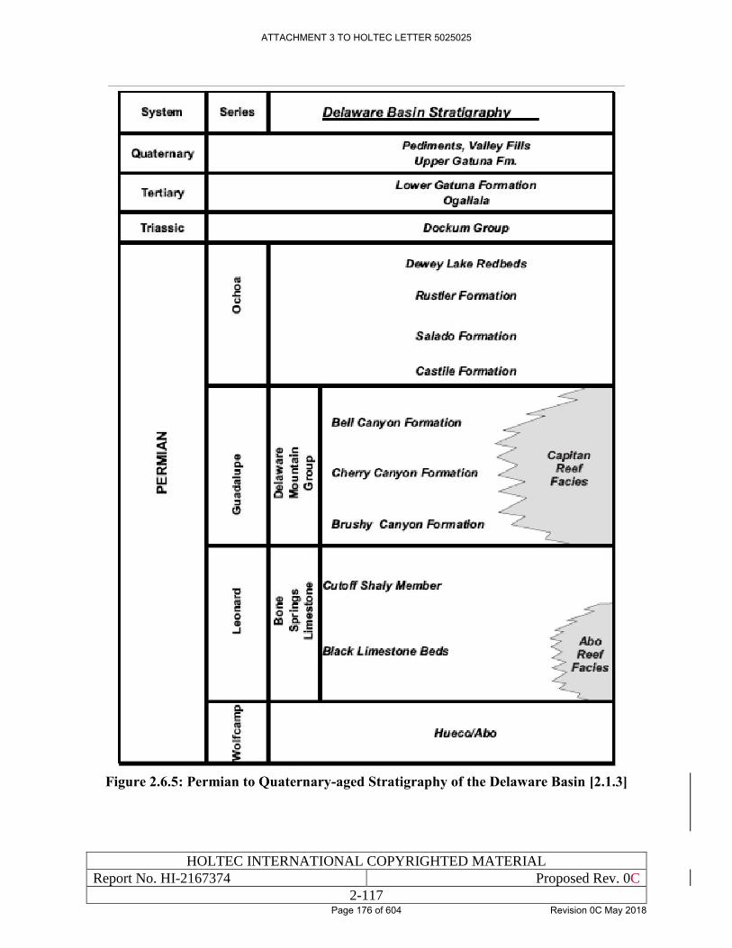
HOLTEC INTERNATIONAL COPYRIGHTED MATERIAL
Report No. HI-2167374 Proposed Rev. 0C
2-117
Figure 2.6.5: Permian to Quaternary-aged Stratigraphy of the Delaware Basin [2.1.3]
ATTACHMENT 3 TO HOLTEC LETTER 5025025
Page 176 of 604 Revision 0C May 2018
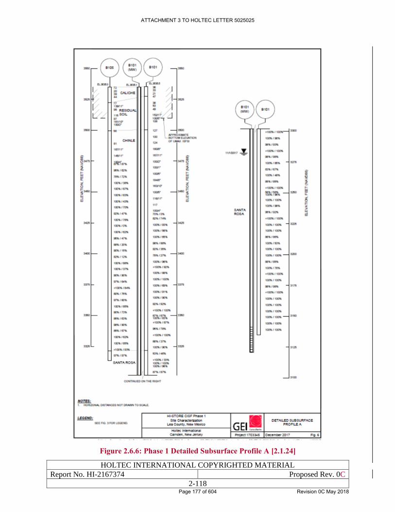
HOLTEC INTERNATIONAL COPYRIGHTED MATERIAL
Report No. HI-2167374 Proposed Rev. 0C
2-118
Figure 2.6.6: Phase 1 Detailed Subsurface Profile A [2.1.24]
ATTACHMENT 3 TO HOLTEC LETTER 5025025
Page 177 of 604 Revision 0C May 2018
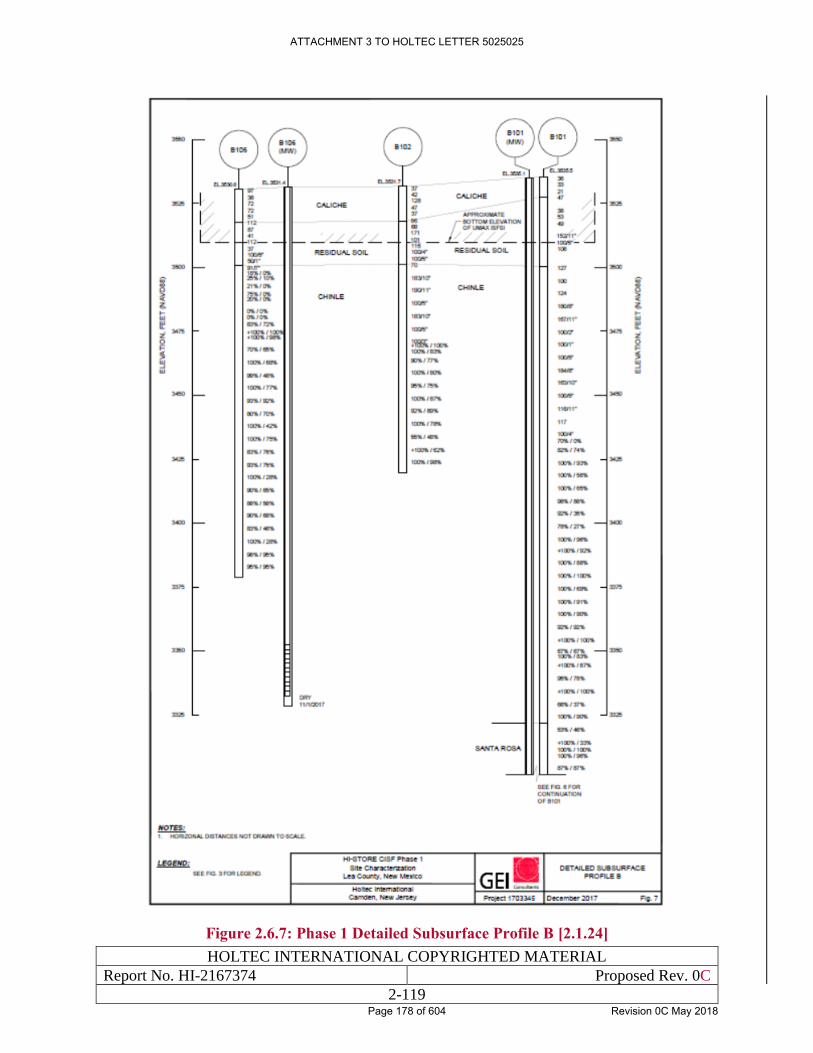
HOLTEC INTERNATIONAL COPYRIGHTED MATERIAL
Report No. HI-2167374 Proposed Rev. 0C
2-119
Figure 2.6.7: Phase 1 Detailed Subsurface Profile B [2.1.24]
ATTACHMENT 3 TO HOLTEC LETTER 5025025
Page 178 of 604 Revision 0C May 2018
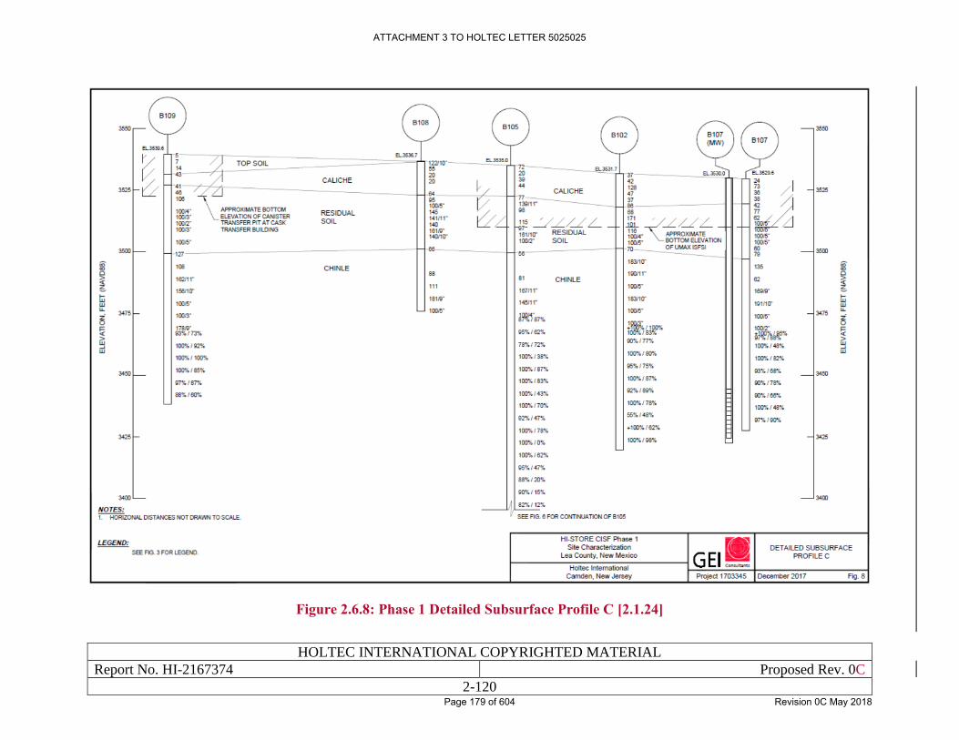
HOLTEC INTERNATIONAL COPYRIGHTED MATERIAL
Report No. HI-2167374 Proposed Rev. 0C
2-120
Figure 2.6.8: Phase 1 Detailed Subsurface Profile C [2.1.24]
ATTACHMENT 3 TO HOLTEC LETTER 5025025
Page 179 of 604 Revision 0C May 2018
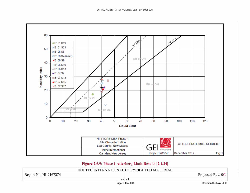
HOLTEC INTERNATIONAL COPYRIGHTED MATERIAL
Report No. HI-2167374 Proposed Rev. 0C
2-121
Figure 2.6.9: Phase 1 Atterberg Limit Results [2.1.24]
ATTACHMENT 3 TO HOLTEC LETTER 5025025
Page 180 of 604 Revision 0C May 2018
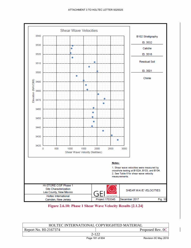
HOLTEC INTERNATIONAL COPYRIGHTED MATERIAL
Report No. HI-2167374 Proposed Rev. 0C
2-122
Figure 2.6.10: Phase 1 Shear Wave Velocity Results [2.1.24]
ATTACHMENT 3 TO HOLTEC LETTER 5025025
Page 181 of 604 Revision 0C May 2018
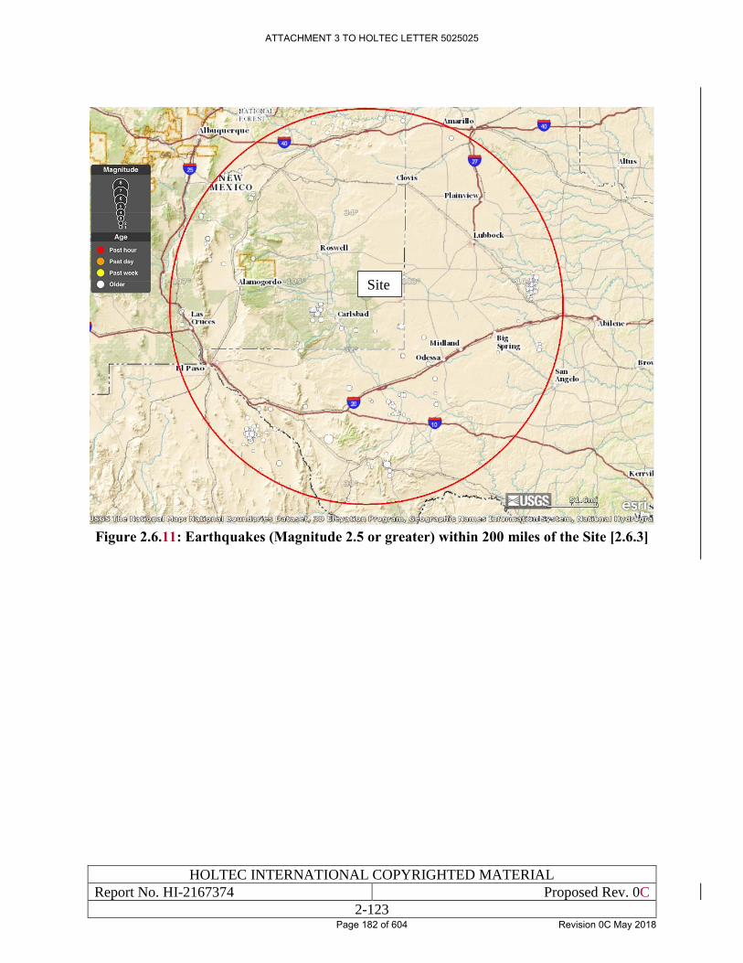
HOLTEC INTERNATIONAL COPYRIGHTED MATERIAL
Report No. HI-2167374 Proposed Rev. 0C
2-123
Figure 2.6.11: Earthquakes (Magnitude 2.5 or greater) within 200 miles of the Site [2.6.3]
Site
ATTACHMENT 3 TO HOLTEC LETTER 5025025
Page 182 of 604 Revision 0C May 2018
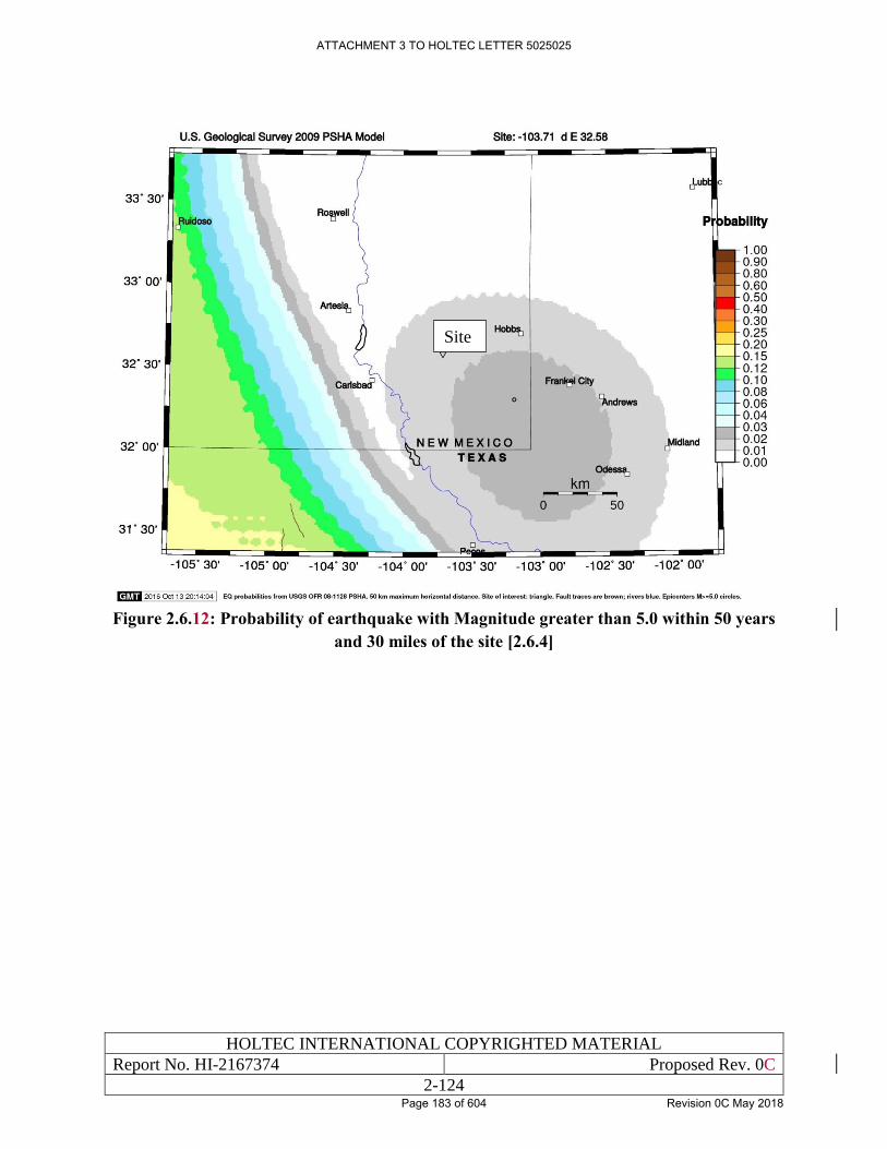
HOLTEC INTERNATIONAL COPYRIGHTED MATERIAL
Report No. HI-2167374 Proposed Rev. 0C
2-124
Figure 2.6.12: Probability of earthquake with Magnitude greater than 5.0 within 50 years
and 30 miles of the site [2.6.4]
Site
ATTACHMENT 3 TO HOLTEC LETTER 5025025
Page 183 of 604 Revision 0C May 2018
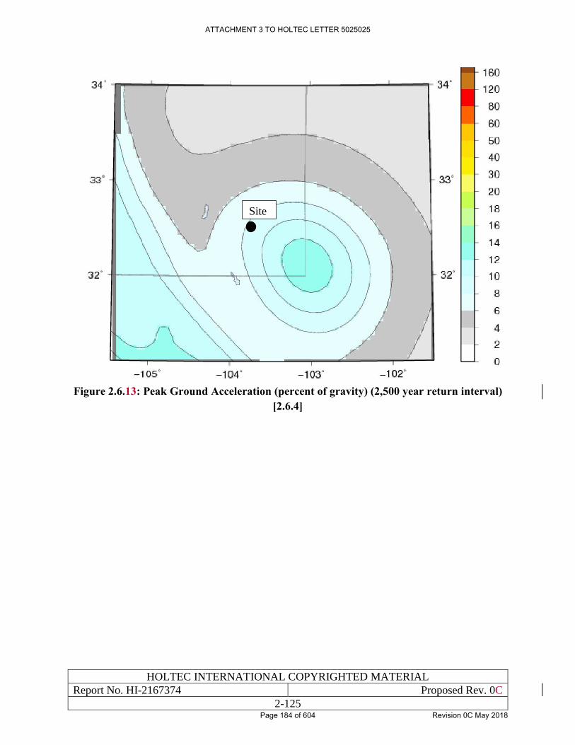
HOLTEC INTERNATIONAL COPYRIGHTED MATERIAL
Report No. HI-2167374 Proposed Rev. 0C
2-125
Figure 2.6.13: Peak Ground Acceleration (percent of gravity) (2,500 year return interval)
[2.6.4]
Site
ATTACHMENT 3 TO HOLTEC LETTER 5025025
Page 184 of 604 Revision 0C May 2018
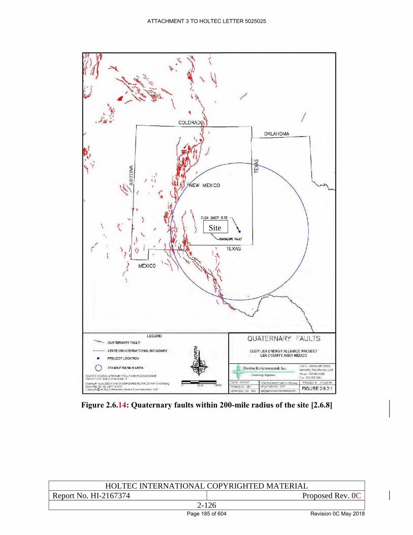
HOLTEC INTERNATIONAL COPYRIGHTED MATERIAL
Report No. HI-2167374 Proposed Rev. 0C
2-126
Figure 2.6.14: Quaternary faults within 200-mile radius of the site [2.6.8]
Site
ATTACHMENT 3 TO HOLTEC LETTER 5025025
Page 185 of 604 Revision 0C May 2018
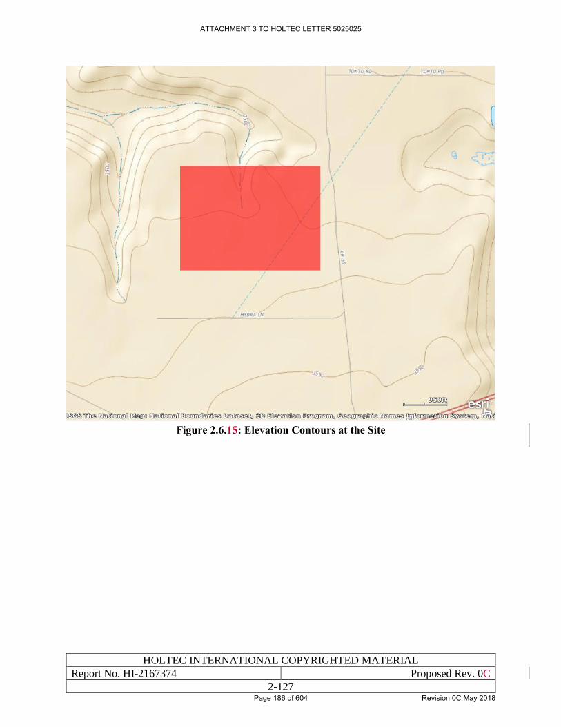
HOLTEC INTERNATIONAL COPYRIGHTED MATERIAL
Report No. HI-2167374 Proposed Rev. 0C
2-127
Figure 2.6.15: Elevation Contours at the Site
ATTACHMENT 3 TO HOLTEC LETTER 5025025
Page 186 of 604 Revision 0C May 2018
HOLTEC INTERNATIONAL COPYRIGHTED MATERIAL
Report No. HI-2167374 Proposed Rev. 0C
2-128
2.7 SITE SPECIFIC DATA FOR THERMAL AND STRUCTURAL
ANALYSES
The site characterization effort, summarized in this chapter, enables a conservative set of
parameters important to thermal and structural analyses to be established. These parameters are
summarized in Table 2.7.1 and are used in Chapter 5 (Structural) and Chapter 6 (Thermal). The
ambient temperature in Table 2.7.1 is based on the meteorological data for the site with a small
margin added for conservatism.
The 10,000-year return earthquake, adopted as the Design Basis Earthquake (DBE) for the HI-
STORE facility, is bounded by the classical Reg. Guide 1.60 response spectrum with its ZPAs
denoted in Table 2.7.1. Likewise, the assumed bounding tornado missiles considered for the Site
are based on the regulatory guidance and a national standard [2.7.1, 2.7.2]. These are the same
missiles considered for the HI-STORM FW MPC Storage System in Docket 72-1032 and the HI-
STORM UMAX Canister Storage System in Docket 72-1040.
ATTACHMENT 3 TO HOLTEC LETTER 5025025
Page 187 of 604 Revision 0C May 2018
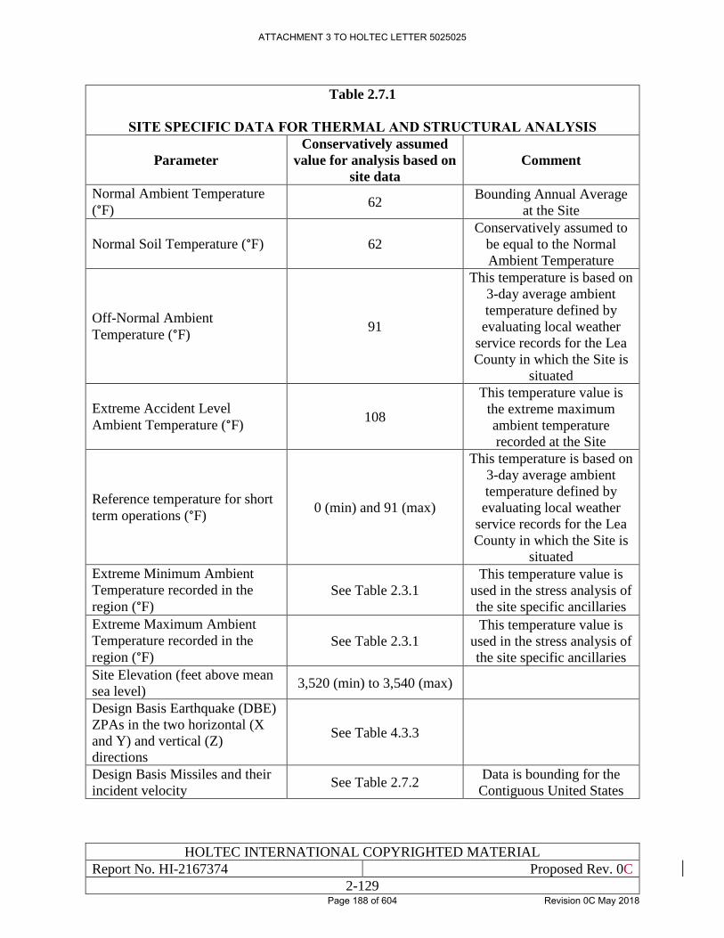
HOLTEC INTERNATIONAL COPYRIGHTED MATERIAL
Report No. HI-2167374 Proposed Rev. 0C
2-129
Table 2.7.1
SITE SPECIFIC DATA FOR THERMAL AND STRUCTURAL ANALYSIS
Parameter
Conservatively assumed
value for analysis based on
site data
Comment
Normal Ambient Temperature
(°F) 62
Bounding Annual Average
at the Site
Normal Soil Temperature (°F) 62
Conservatively assumed to
be equal to the Normal
Ambient Temperature
Off-Normal Ambient
Temperature (°F) 91
This temperature is based on
3-day average ambient
temperature defined by
evaluating local weather
service records for the Lea
County in which the Site is
situated
Extreme Accident Level
Ambient Temperature (°F) 108
This temperature value is
the extreme maximum
ambient temperature
recorded at the Site
Reference temperature for short
term operations (°F) 0 (min) and 91 (max)
This temperature is based on
3-day average ambient
temperature defined by
evaluating local weather
service records for the Lea
County in which the Site is
situated
Extreme Minimum Ambient
Temperature recorded in the
region (°F)
See Table 2.3.1
This temperature value is
used in the stress analysis of
the site specific ancillaries
Extreme Maximum Ambient
Temperature recorded in the
region (°F) See Table 2.3.1
This temperature value is
used in the stress analysis of
the site specific ancillaries
Site Elevation (feet above mean
sea level) 3,520 (min) to 3,540 (max)
Design Basis Earthquake (DBE)
ZPAs in the two horizontal (X
and Y) and vertical (Z)
directions
See Table 4.3.3
Design Basis Missiles and their
incident velocity See Table 2.7.2
Data is bounding for the
Contiguous United States
ATTACHMENT 3 TO HOLTEC LETTER 5025025
Page 188 of 604 Revision 0C May 2018
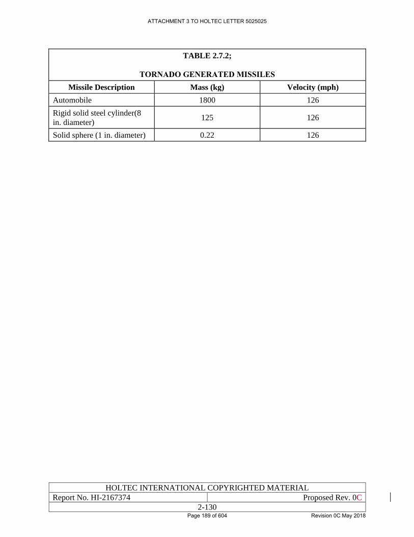
HOLTEC INTERNATIONAL COPYRIGHTED MATERIAL
Report No. HI-2167374 Proposed Rev. 0C
2-130
TABLE 2.7.2;
TORNADO GENERATED MISSILES
Missile Description Mass (kg) Velocity (mph)
Automobile 1800 126
Rigid solid steel cylinder(8
in. diameter) 125 126
Solid sphere (1 in. diameter) 0.22 126
ATTACHMENT 3 TO HOLTEC LETTER 5025025
Page 189 of 604 Revision 0C May 2018
HOLTEC INTERNATIONAL COPYRIGHTED MATERIAL
Report No. HI-2167374 Proposed Rev. 0C
2-131
2.8 SAFETY-RELEVANT ENVIRONMENTAL DETERMINATIONS
The geotechnical information on the proposed HI-STORE CIS Facility presented in this chapter
may be summarized in the following points:
• The facility will be located in one of the most sparsely populated areas in the continental
United States. The nearest population centers are the cities of Carlsbad (32 miles away)
and Hobbs (34 miles away).
• The topography of the land is relatively flat lending to effective intrusion detection by
camera surveillance.
• The water table is sufficiently below the bottom of the subterranean HI-STORM UMAX
system to preclude the possibility of any ground water intrusion in the storage cavity
spaces.
• The land is fallow with limited vegetation to support cattle herds.
• The annual rainfall is meager requiring a modest water drainage infrastructure.
• The tornadic activity in the region is infrequent. The strength of the tornadoes is bounded
by the national meteorological tornadic data which has been used to define the Design
Basis Missiles for both the HI-STORM FW system and the HI-STORM UMAX system.
Therefore, the storage system’s ability to withstand the site specific tornados is
axiomatically satisfied.
• There are no active volcanoes in the area.
• The area has a stable tectonic plate profile. As a result, the 10,000 year-return earthquake
for the site is quite modest and well below the range for which HI-STORM UMAX as
licensed in Docket 72-1040.
• There are no chemical plants in the area that would spew aggressive species into the
environment. As a result, the ambient air is non-aggressive and a long service life of the
stored stainless steel canisters can be predicted with confidence.
• There is no air force base or a major civilian airport in the vicinity of the site and the area
is ostensibly not used for any aerial training exercises by the US military.
• The local area has a well-developed rail road infrastructure. The length of additional rail
spur required for the site in less than 10 miles.
• By agreement with the applicable third parties, the oil drilling and phosphate extraction
activities have been proscribed at and around the site.
The above considerations lead to the conclusion that the proposed Site is suitable for its intended
purpose.
ATTACHMENT 3 TO HOLTEC LETTER 5025025
Page 190 of 604 Revision 0C May 2018
HOLTEC INTERNATIONAL COPYRIGHTED MATERIAL
Report No. HI-2167374 Proposed Rev. 0C
2-132
2.9 REGULATORY COMPLIANCE
Pursuant to the guidance provided in NUREG-1567, the foregoing material in this Chapter
provides:
i. A complete description of the Geography and Demography of the Site as mandated by 10
CFR 72.24, 72.90, 72.96, 72.98, and 72.100;
ii. A complete identification and description of key characteristics of Nearby Facilities as
mandated by 10 CFR 72.24, 72.40, 72.90, 72.94, 72.96, 72.98, 72.100, and 72.122;
iii. A complete description of the Meteorology and Surface Hydrology of the Site as mandated
by 10 CFR 72.24, 72.40, 72.90, 72.92, 72.98, and 72.122;
iv. A complete description of the Subsurface Hydrology of the Site as mandated by 10 CFR
72.24, 72.98, and 72.122;
v. A complete description of the Geology and Seismology of the Site as mandated by 10 CFR
72.24, 72.40, 72.90, 72.92, 72.98, 72.102, and 72.122;
Therefore, it can be concluded that this SAR provides adequate description and safety assessment
of the site which this ISFSI Facility is to be located, in accordance with 10 CFR 72.24(a).
Additionally, it can be concluded that the proposed site complies with the criteria of 10 CFR 72
Subpart E, as required by 10 CFR 72.40(a)(2).
ATTACHMENT 3 TO HOLTEC LETTER 5025025
Page 191 of 604 Revision 0C May 2018
HOLTEC INTERNATIONAL COPYRIGHTED MATERIAL
Report No. HI-2167374 Proposed Rev. 0A
3-1
CHAPTER 3: OPERATIONS AT THE HI-STORE CIS
FACILITY
3.0 INTRODUCTION
This chapter describes the activities and operations antecedent to safely emplacing a loaded
canister in the HI-STORM UMAX VVM at the HI-STORE CIS facility. Chapter 9 of the HI-
STORM UMAX FSAR [1.0.6] and the HI-STORM FW FSAR [1.3.7] describe the operations
carried out at a nuclear plant to implement on-site dry storage. While fuel loading operations are
not a part of the activities at the HI-STORE CIS facility, an informational description is provided
herein for reference. As the narrative in this chapter explains, the systems and operations required
to effectuate transfer of canisters to the HI-STORM UMAX at HI-STORE meet the intent of
10CFR72.122 in full measure.
In particular, it is shown that the loading operations are characterized by a number of defense-in-
depth measures, described in Chapter 4 and evaluated in Chapter 15, that are intended to preclude
a handling accident or ALARA transgression. The defense-in-depth measures include:
• All lifting and handling devices comply with ANSI 14.6 [1.2.4] with the added requirement
that the weakening effect of temperature on the strength of the lifting device is included.
• The standard lifting and handling devices, such as the Vertical Cask Transporter (VCT)
comply with the added structural margin requirements set down in Chapter 4 of this SAR.
• The VCT, a key piece of equipment in heavy load handling evolutions, is equipped with a
redundant drop protection features.
• The kinematic stability of the loaded equipment for every stability-vulnerable handling
evolution under the site’s Design Basis Earthquake (DBE) has been established by
appropriate analysis.
• All lifting and handling devices are designed to maintain the CG of the lifted SSC aligned
with the lift point at all times thus precluding an unstable lift.
• Custom engineered shielding accessories are utilized to meet ALARA goals.
• The gantry crane employed at the facility is designed to be single failure proof in
compliance with ASME NOG-1 [3.0.1].
• All operations will be performed in accordance with written and QA validated procedures.
• The HI-STORE CIS facility is a “start clean, stay clean” facility. This means the arriving
package from the sender plant site has been assayed and declared the package to be free of
any external contamination.
• The HI-STORE facility is a zero effluent site; no liquid or gaseous effluents are a part of
any operation at the facility.
All references are in placed within square brackets in this report and are compiled in Chapter 19 in this report.
ATTACHMENT 3 TO HOLTEC LETTER 5025025
Page 192 of 604 Revision 0C May 2018
HOLTEC INTERNATIONAL COPYRIGHTED MATERIAL
Report No. HI-2167374 Proposed Rev. 0A
3-2
• Even though not required to maintain stability during the site’s DBE, the HI-TRAC CS
transfer cask is secured by anchor bolts during all operations involving transfer of the
loaded canister.
The information presented in this chapter along with the technical basis of the system design
described in the canister’s FSAR in its host 10CFR72 docket will be used to develop detailed
operating procedures. In preparing the procedures, the conditions of the license and technical
specifications, equipment-specific operating instructions, as well as the information in this chapter
will be utilized to ensure that the short-term operations shall be carried out with utmost safety and
ALARA.
The following generic criteria shall be used to determine whether the site-specific operating
procedures developed pursuant to the guidance in this chapter are acceptable for use:
• All heavy load handling instructions are in keeping with the guidance in industry standards
and Holtec’s Rigging Manual.
• The procedures are in conformance with this SAR and its CoC.
• The procedures are in conformance with the canister’s native FSAR (HI-STORM FW
System FSAR for MPC-89 and MPC-37) [1.3.7].
• The operational steps are ALARA.
• The procedures contain provisions for documenting successful execution of all safety
significant steps for archival reference.
• Procedures contain provisions for classroom and hands-on training and for a Holtec-
approved personnel qualification process to ensure that all operations personnel are
adequately trained.
• The procedures are sufficiently detailed and articulated to enable craft labor to execute
them in literal compliance with their content.
Written procedures are required to be developed or modified to account for such items as handling
and storage of systems, structures and components (SSCs) identified as important-to-safety, heavy
load handling, specialized instrument calibration, special nuclear material accountability, fuel
handling procedures, training, equipment, and process qualifications. The HI-STORE CIS facility
management organization shall implement controls to ensure that all critical set points (e.g., Lift
Weights) do not exceed the design limit of the specific equipment.
Control of the operation shall be performed in accordance with Holtec’s Quality Assurance (QA)
program to ensure critical steps are not overlooked and the canister has been confirmed to meet all
requirements of the license before being released for on-site storage under 10CFR72.
The organization of the material and contents in this chapter follows the guidelines of NUREG-
1567 [1.0.3].
ATTACHMENT 3 TO HOLTEC LETTER 5025025
Page 193 of 604 Revision 0C May 2018
HOLTEC INTERNATIONAL COPYRIGHTED MATERIAL
Report No. HI-2167374 Proposed Rev. 0A
3-3
3.1 DESCRIPTION OF OPERATIONS
Operations related to the loading and closure of the canisters of spent fuel to be stored at HI-
STORE are performed at the originating nuclear power plant. Spent fuel operations at the
originating power plant are performed in accordance with the originating plant Owner’s 10CFR50
license, any 10CFR72 site-specific and generic licenses, as well as the Technical Specification of
the storage system. Transport of the spent fuel from the plant to HI-STORE is performed in
accordance with the requirements of 10CFR71 [1.3.2] and 49CFR171, 172, 173, 174, and 177
[3.1.2, 3.1.3, 10.3.1, 3.1.4, 3.1.5]. The HI-STORE facility will be designed to receive fuel from
any licensed canister-based transportation cask. Storage of the spent fuel at HI-STORE is subject
to the requirements of the HI-STORE CIS facility license issued pursuant to the regulations of
10CFR72. Compliance with 10CFR72 regulations [1.0.5] begins when the transportation cask
enters the Cask Transfer Building (CTB).
The operations that are performed at HI-STORE include the following:
• Receipt and inspection of incoming transportation casks with canisters containing spent
nuclear fuel.
• Transfer of canisters from transportation cask to the HI-TRAC CS transfer cask in the
Canister Transfer Facility (CTF).
• Transfer of the HI-TRAC CS to the HI-STORM UMAX at the subterranean ISFSI.
• Surveillance of HI-STORM UMAX system.
• Security of HI-STORE.
• Health Physics at HI-STORE.
• Maintenance at HI-STORE.
• Removal of canisters from HI-STORE.
• Inventory documentation management.
Principal operations at the HI-STORE CIS facility involve activities pertaining to handling,
transfer and placement of canisters in the facility’s VVMs. Future removal of canisters for off-
site shipment will involve the reverse of the loading operations. During storage at the HI-STORE
facility, several supporting activities are required including monitoring of the storage systems and
periodic maintenance of onsite equipment. Holtec International will implement detailed
procedures for operating, inspecting, and testing the HI-STORE CIS facility SSCs in accordance
with configuration–controlled written procedures similar to the ones employed at its existing user’s
ISFSIs. These procedures will ensure that the spent fuel handling and storage operations are in
accordance with the HI-STORE SAR and the Company’s Nuclear Safety and QA programs.
The following description provides an overview of the operational process for the spent fuel
storage facility systems. Detailed step-by-step operations are described in Chapter 10.
3.1.1 Operations at Originating Nuclear Power Plant
ATTACHMENT 3 TO HOLTEC LETTER 5025025
Page 194 of 604 Revision 0C May 2018
HOLTEC INTERNATIONAL COPYRIGHTED MATERIAL
Report No. HI-2167374 Proposed Rev. 0A
3-4
The spent fuel operations at the originating nuclear power plant and the transport of the loaded
canisters to the HI-STORE facility are not a part of HI-STORE operations. The description
provided in this subsection is for information only; for a detailed description the reader should
consult the canister’s host FSAR such as HI-STORM UMAX FSAR [1.0.6].
Typically, an empty canister is placed inside a transfer cask. The canister and transfer cask are
placed into the spent fuel pool where the canister is loaded with spent fuel. The canister exterior
is prevented from direct contact with potentially contaminated spent fuel pool water by means of
a slightly-pressurized clean water annulus with an inflatable top seal. Once the fuel is loaded, the
canister lid is placed on the canister and the transfer cask is removed from the spent fuel pool. The
canister lid is seal welded to the canister and the canister is drained and dried. The canister is then
backfilled with inert helium gas and the drain and fill ports are welded closed and leak tested. The
closure ring is installed and seal welded, thereby sealing the canister. The outer surfaces of the
transfer cask and the accessible areas of the canister are then checked for surface contamination
and decontaminated, if necessary.
Most sealed canisters are placed in dry storage at the nuclear power plant.
At the time of transport, the sealed canister is recovered from storage into the transfer cask and
placed in a transportation cask. The transportation cask, containing the loaded canister, is sealed
using a bolted top closure lid. The transportation cask annulus is evacuated and backfilled with
helium. The closure lid seals are leak tested and the transportation cask is placed horizontally on
a transport frame secured to a transport vehicle. The transportation cask is fitted with impact
limiters, tie-downs and a personnel barrier to protect personnel from coming in direct contact with
the cask body. The transportation cask is then shipped to HI-STORE.
3.1.2 Operations Between the Originating Nuclear Power Plant and HI-STORE
The HI-STORE facility is designed to receive spent fuel waste packages shipped by rail car. Prior
to shipment, the originating nuclear power plant must verify that cask storage document packages
are included with the transportation cask. These document packages should contain information
such as the cask’s CCRs, any 10CFR72.48 documentation, aging management records and
documentation of the fuel contents of the cask. These document packages will be checked once
again when the cask arrives at the HI-STORE site. During transportation, the transportation cask
provides a part 71-compliant containment for the canister that is qualified to withstand all
applicable licensing basis accidents (10CFR71.73). The package (transportation cask and impact
limiters) is licensed in accordance with the requirements of 10CFR71, “Packaging and
Transportation of Radioactive Material”, and complies with the requirements of 49CFR171,
“General Information, Regulations, and Definitions”, 49CFR172, “Hazardous Materials Tables
and Hazardous Materials Communications Regulations”, 49CFR173, “Shippers – General
Requirements for Shipments and Packages”, 49CFR174, “Carriage by Rail”, and 49CFR177,
“Carriage by Public Highway” [3.1.2, 3.1.3, 10.3.1, 3.1.4, 3.1.5].
3.1.3 Operations Between the Railroad Mainline and HI-STORE
To reach the HI-STORE site, the transportation rail car is transferred to a newly constructed rail
spur located along State Highway 243, where the transportation casks remain on the rail car and
are transported approximately 5 miles east to the HI-STORE CIS facility.
3.1.4 Operations at HI-STORE
ATTACHMENT 3 TO HOLTEC LETTER 5025025
Page 195 of 604 Revision 0C May 2018
HOLTEC INTERNATIONAL COPYRIGHTED MATERIAL
Report No. HI-2167374 Proposed Rev. 0A
3-5
This section provides a summary overview of the canister handling and normal storage operations
at HI-STORE CIS facility. A more detailed description is provided in Chapter 10. Radiation
exposure to facility workers and the general public will be maintained as low as reasonably
achievable (ALARA) during all operations in accordance with the facility’s radiation protection
program described in Chapter 11. Table 11.3.1 of Chapter 11 provides detailed estimates of
expected durations and dose to facility workers for all canister handling operations.
3.1.4.1 Receipt and Inspection of Incoming Transportation Cask and Canister
During spent fuel transportation, the sealed canister is contained within the transportation cask,
which is mounted horizontally on a rail car or heavy haul trailer. Impact limiters are mounted on
both ends of the transportation cask and a personnel barrier covers the transportation cask between
the impact limiters. A tie-down secures the cask to the transport vehicle. Figure 3.1.1 pictorially
illustrates the cask handling operations.
When the transportation cask arrives at the HI-STORE CIS facility, the transportation cask is
visually inspected for any outward indications of damage or degradation prior to entry into the
Protected Area (PA). Canister records are reviewed to certify that the canister meets the material
considerations of Chapter 17 and the receipt inspection requirements of Chapter 9 to ensure the
canister continues to meet the no-credible-leakage criteria to which it has been certified in the HI-
STORM UMAX docket [1.0.6]. Additionally, a review of the transportation documentation
package, which includes verification that a pre-shipment inspection was performed and acceptable,
is mandatory prior to receiving a transportation cask into the security vehicle trap.
After initial receipt approval, the cask is moved into the security vehicle trap for physical
inspection by security personnel to ensure no unauthorized devices or materials enter the PA.
When security clearance is complete, the shipment proceeds into the PA and into the CTB (Figure
3.1.2) where the personnel barrier and tie-down are removed. The transportation cask, in
accordance with the Part 71 requirements, is surveyed for dose rates and contamination levels.
The dose rate from the cask on arrival at the HI-STORE CIS facility must be in reasonable accord
with the measured dose rate at the originating plant. An excessive discrepancy would warrant a
root cause evaluation under Holtec’s quality program and appropriate notification to the USNRC.
3.1.4.2 Transfer of Canister from Transportation Cask to HI-TRAC CS
The steps for transferring the sealed canister from the transportation cask to the HI-TRAC CS all
occur within the CTB. Using the CTB crane, the transportation cask is lifted from the rail car
horizontally and placed onto a tilt frame suitable for the transportation cask being handled. The
tilt frame fully supports the cask in the horizontal orientation and allows for cask tilting between
the vertical and horizontal orientations. With the transportation cask in the horizontal orientation
(fully supported by the tilt frame), the impact limiters are removed and placed aside. The
transportation cask closure lid penetration cover is removed and the annulus gas is sampled to
confirm the continued effectiveness of the canister’s confinement barrier. Following successful
testing of the annulus gas, a canister leakage test is performed. The transportation cask is then
tilted to vertical, lifted from the tilting frame and placed in the Canister Transfer Facility (CTF).
An alignment plate is used to concentrically align the HI-TRAC CS to the transportation cask. The
alignment plate provides shielding to personnel performing the canister transfer and allows access
for examination of the canister exterior shell surface.
ATTACHMENT 3 TO HOLTEC LETTER 5025025
Page 196 of 604 Revision 0C May 2018
HOLTEC INTERNATIONAL COPYRIGHTED MATERIAL
Report No. HI-2167374 Proposed Rev. 0A
3-6
After the cask is installed in the CTF, the closure lid is removed and a cask seal surface protector
is installed on the transportation cask’s closure lid seal surface to protect it from damage. If
necessary, any canister shipping spacers are removed. With the canister lid exposed, a
contamination survey is taken on the accessible areas of the canister lid to verify that the canister
is free of removable contamination. The MPC lifting attachment is then connected to the lid.
Temporary shielding may be positioned as required to maintain worker dose ALARA.
The HI-TRAC CS is then placed on the CTF alignment plate with its bottom doors open. The CTF
anchor studs are secured to the HI-TRAC CS bottom flange to assure the cask’s seismic stability
during the canister transfer process. The MPC lifting device extension is attached to the overhead
crane, lowered through the HI-TRAC CS body using the CTB crane, and connected to the MPC
lift attachment. The MPC is lifted into the HI-TRAC CS and the HI-TRAC CS shield gates are
closed. With the canister is resting on the shield gates, the MPC lifting device extension is
disconnected from the MPC lift attachment. The loaded HI-TRAC CS is then lifted and placed at
a location on the floor that is readily accessible to the VCT. It is at this time that the HI-TRAC
CS will be surveyed for dose measurements.
3.1.4.3 Placement of the Canisters into the Vertical Ventilated Modules (VVMs)
The HI-TRAC CS loading is now complete and ready for transport to the designated HI-STORM
UMAX VVM on the storage pad. In preparation for receiving the loaded canister, the designated
VVM’s CEC lid is removed and the Divider Shell is installed in the CEC. The VCT lifts the HI-
TRAC CS and moves it out of the CTB. The cask is then moved to the appropriate HI-STORM
UMAX location by the VCT. The HI-TRAC CS is positioned and lowered onto the ISFSI pad
over the CEC to be loaded. Once it is lowered on the pad, the HI-TRAC CS is secured to the CEC
in similar manner as at the CTF. The VCT releases from the HI-TRAC CS lifting trunnions and
raises the top lift beam. The MPC lifting device extension connects the MPC lift attachment to
the VCT through the VCT’s top lift beam. The VCT’s top lift beam is raised to tension the canister
lift slings and raise the canister slightly. The HI-TRAC CS shield gates are opened and the VCTs
top lift beam is lowered to lower the canister into the CEC. This continues until the canister is fully
seated in the CEC. The MPC lift device extension releases from the VCT’s top lift beam. The
VCT reconnects to the HI-TRAC CS lifting trunnions. The HI-TRAC CS shield gates are closed
and the securing anchor studs and nuts are removed. HI-TRAC CS is lifted and removed from the
HI-STORM UMAX location. The MPC lift attachment is unbolted from the canister lid and
removed from the CEC. If necessary, the CEC-to-lid seals are installed and the HI-STORM
UMAX Closure Lid is installed. The lid rigging is removed and the CEC lid vent screen is
installed. Once the rigging is removed and the closure lid is installed, the VVM will be surveyed
for dose measurements.
3.1.4.4 Surveillance of the HI-STORM UMAX Storage Systems
While in storage, the proper monitoring of the HI-STORM UMAX storage systems is subject to
surveillance guided by written procedures. The temperature of the exiting air from the VVMs
provides a telltale indication of compliance with the Technical Specifications. In addition, the
cask air vent covers are visually inspected for blockages. An overall site observation surveillance
is also performed on a periodic basis to monitor for adverse conditions such as the accumulation
of site debris around the air vents, tearing of the vent screens and the like.
ATTACHMENT 3 TO HOLTEC LETTER 5025025
Page 197 of 604 Revision 0C May 2018
HOLTEC INTERNATIONAL COPYRIGHTED MATERIAL
Report No. HI-2167374 Proposed Rev. 0A
3-7
Dose rates associated with individual storage systems are measured. This is to ensure adequate
shielding of the canister so that radiation exposure to the general public is minimized and
occupational doses to personnel working in the vicinity of the storage casks are maintained
ALARA. Radiation doses emitted from the storage casks are measured by thermoluminescent
dosimeters (TLDs) located at the protected area (PA) and owner controlled area (OCA) boundaries
to ensure doses are within 10CFR20.1301 and 10CFR72.104 or 40CFR191 limits.
3.1.4.5 Security Operations
Security personnel coordinate security related functions that include performing continual
surveillance for intruders, responding to intrusion alarms, processing visitors and workers to HI-
STORE, searching packages and vehicles, issuing badges to workers, coordinating with local law
enforcement agencies, and coordination with appropriate site and off-site emergency response
personnel. Security personnel are also responsible for identifying and assessing off-normal and
emergency events during off-shift hours of HI-STORE operation. Details for the security
personnel are discussed in the HI-STORE Physical Security Plan [3.1.1].
3.1.4.6 Health Physics Operations
The health physics (HP) personnel are responsible for measuring, monitoring and recording all
radiological aspects of the HI-STORE facility. These include: taking radiation dose and
contamination surveys on incoming spent fuel shipments, monitoring individual radiological
exposure, issuing, monitoring and maintaining personnel dosimetry, evaluating off-site
radiological conditions, placarding and establishing radiological working conditions, reporting on
radiological conditions to appropriate authorities and maintenance of radiological survey
equipment. In order to uphold the HI-STORE philosophy of “Start Clean/Stay Clean” HP
personnel ensure that contamination levels on the canisters of incoming shipments meet site
requirements. Canisters exceeding the limits will be returned to the originating power plant for
dispositioning.
During the transfer process, HP personnel monitor doses to ensure that workers are not exposed to
unnecessary radiation. In the event high dose rates are detected, temporary shielding, in the form
of lead blankets, neutron shielding, portable shield walls, etc., are used to maintain ALARA. HP
Personnel perform dose rate surveillances of the loaded storage cask to ensure requirements are
met.
In addition to surveillance activities, the HP department monitors onsite and offsite radiation levels
to ensure worker and offsite doses are in accordance with regulatory requirements. The HP
department is also responsible for calibrating radiation protection instrumentation.
3.1.4.7 Maintenance Operations
Because of their passive nature, the HI-STORM UMAX storage system requires little maintenance
over the lifetime of HI-STORE. Typical maintenance tasks may involve occasional replacement
and recalibration of temperature monitoring instrumentation, repair of coatings, repair of damaged
screens, and general removal of dirt and debris.
Periodic maintenance is required on the overhead bridge crane, service cranes, transfer equipment,
HI-TRAC CS and transportation casks. Maintenance of SSCs, which are classified as important-
to-safety, ensure that they are safe and reliable throughout the life of HI-STORE per
ATTACHMENT 3 TO HOLTEC LETTER 5025025
Page 198 of 604 Revision 0C May 2018
HOLTEC INTERNATIONAL COPYRIGHTED MATERIAL
Report No. HI-2167374 Proposed Rev. 0A
3-8
10CFR72.122(f). Work on these items will only occur when the equipment being maintained is
in the unloaded condition.
Maintenance may also be required on the following components: the heavy haul tractor/trailer (if
used), rail car and locomotive (if used), cask transporter, security systems, temperature and
radiation monitoring systems, diesel generator, electrical systems, fire protection systems, building
HVAC and site infrastructure. The CTB and Storage Building provide the facility to perform
maintenance activities. Vehicles may be moved off-site to specialized facilities that are better
suited to perform such activities.
Full details of the maintenance requirements are given in Chapter 10. Additional information on
the Aging Management of HI-STORE SSCs can be found in Chapter 18.
3.1.4.8 Transfer of Canisters from HI-STORE Offsite
The HI-STORE CIS facility is an interim storage facility. At some point in the future, canisters
may be required to be moved offsite. When such a day arrives, a 10CFR71 licensed transportation
cask will transport the canisters offsite to another facility. Transfer operations will utilize the CTB
to transfer the canisters from HI-TRAC CS to the transportation casks. Once loaded in a
transportation cask, the spent fuel canister will be shipped to the designated facility. To
accomplish this, the steps for installing the canister in the VVM are basically reversed, resulting
in a loaded transportation cask ready for transport.
3.1.4.9 Sequence of Operations
Diagrams illustrating the sequence of operations for canister receipt, transfer, and placement into
storage is shown in Figure 3.1.1 for the HI-STORM UMAX storage system.
The number of personnel and the time required for the various operations are provided in Table
11.3.1. This table is used to develop the occupational exposures discussed in Chapter 11.
3.1.5 Identification of Subjects for Safety Analysis
3.1.5.1 Criticality Prevention
Only canisters that have been determined to have no credible leakage shall be stored at the HI-
STORE CIS facility. The determination that the canister’s confinement boundary is intact and
effective to prevent intrusion of any fluids including water is performed at both the plant of origin
and upon its arrival at HI-STORE. Thus, while the canister is qualified to remain subcritical even
in the presence of water by virtue of its fixed basket geometry and fixed neutron absorbers installed
in the canister’s Fuel Basket, the guaranteed absence of water inside the canister at the HI-STORE
CIS facility makes any loss of criticality safety non-credible. Therefore, no additional criticality
prevention measures are needed.
3.1.5.2 Chemical Safety
The HI-STORE CIS facility does not use any chemicals (even water) in its canister handling and
storage operations. Therefore, there are no chemical hazards associated with the operation of HI-
STORE CIS facility.
3.1.5.3 Operation Shutdown Modes
ATTACHMENT 3 TO HOLTEC LETTER 5025025
Page 199 of 604 Revision 0C May 2018
HOLTEC INTERNATIONAL COPYRIGHTED MATERIAL
Report No. HI-2167374 Proposed Rev. 0A
3-9
During storage, there are no operational shutdown modes associated with the HI-STORM UMAX
Storage System since the system is passive and relies on natural air circulation for cooling. During
canister transfer, the transfer process may be shut down at the end of the day, resuming again on a
following day. A discontinuance in the transfer operation is permitted only if:
• All SSCs are in a mechanically secured state,
• No nuclear components are in the lifted condition
• The ventilation flow of air around the canister is uninhibited, and
• The radiation dose around the cask and canister is ALARA.
In summary, all operational shutdown modes at HI-STORE are safe shutdown modes due to the
design features of the facility and operational controls imposed through operating procedures.
3.1.5.4 Instrumentation
Due to the totally passive nature of the storage casks, there is no need for any instrumentation to
perform safety functions. Temperature monitors are utilized as a means to monitor the cask
temperature during storage. Area radiation monitors are used to measure radiation levels in the
CTB during canister transfer operations. Portable radiation monitors are used to measure radiation
levels during the canister transfer process. HI-STORE operators are equipped with personnel
dosimeters whenever they are in the PA. The radiation dose will be monitored at the perimeters
of the PA and OCA. Pursuant to the criteria in NUREG/CR-6407 [1.2.2], the temperature and
radiation monitors are classified as Not-Important-to-Safety.
3.1.5.5 Maintenance Techniques
Maintenance operations on the equipment and systems don’t involve any special techniques that
would require a safety analysis.
Preventative maintenance is performed on a regular basis on the overhead transfer crane, canister
lifting equipment, cask transporter, heavy haul tractor/trailers, radiation detection and monitoring
equipment, cask temperature monitoring equipment, security equipment, fire detection and
suppression equipment, etc. Maintenance is performed in accordance with 10CFR72.122(f), ANSI
N14.6 [1.2.4], and manufacturer’s requirements.
ATTACHMENT 3 TO HOLTEC LETTER 5025025
Page 200 of 604 Revision 0C May 2018
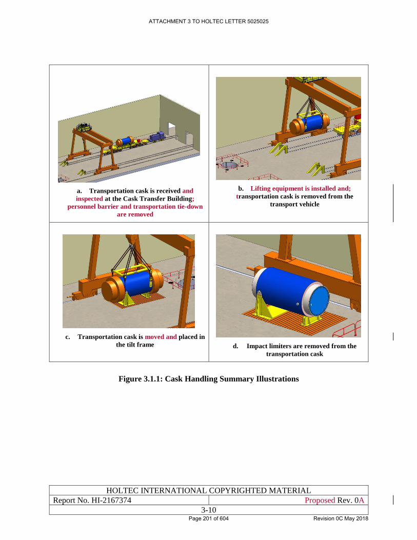
HOLTEC INTERNATIONAL COPYRIGHTED MATERIAL
Report No. HI-2167374 Proposed Rev. 0A
3-10
a. Transportation cask is received and
inspected at the Cask Transfer Building;
personnel barrier and transportation tie-down
are removed
b. Lifting equipment is installed and;
transportation cask is removed from the
transport vehicle
c. Transportation cask is moved and placed in
the tilt frame
d. Impact limiters are removed from the
transportation cask
Figure 3.1.1: Cask Handling Summary Illustrations
ATTACHMENT 3 TO HOLTEC LETTER 5025025
Page 201 of 604 Revision 0C May 2018
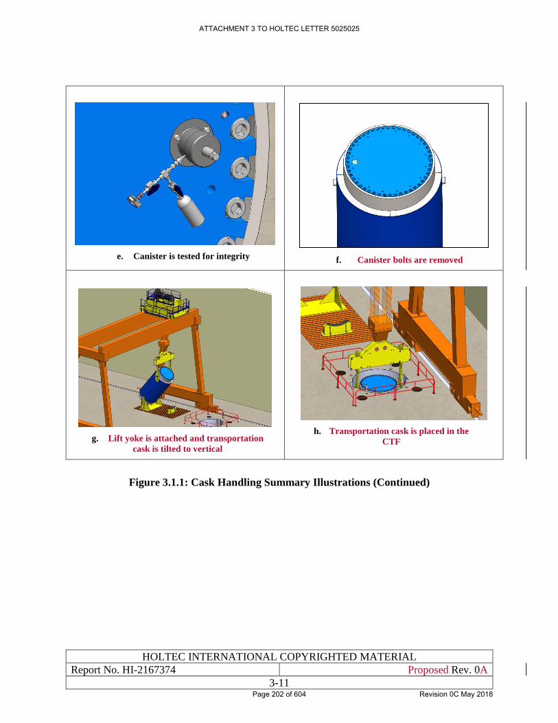
HOLTEC INTERNATIONAL COPYRIGHTED MATERIAL
Report No. HI-2167374 Proposed Rev. 0A
3-11
e. Canister is tested for integrity
f. Canister bolts are removed
g. Lift yoke is attached and transportation
cask is tilted to vertical
h. Transportation cask is placed in the
CTF
Figure 3.1.1: Cask Handling Summary Illustrations (Continued)
ATTACHMENT 3 TO HOLTEC LETTER 5025025
Page 202 of 604 Revision 0C May 2018
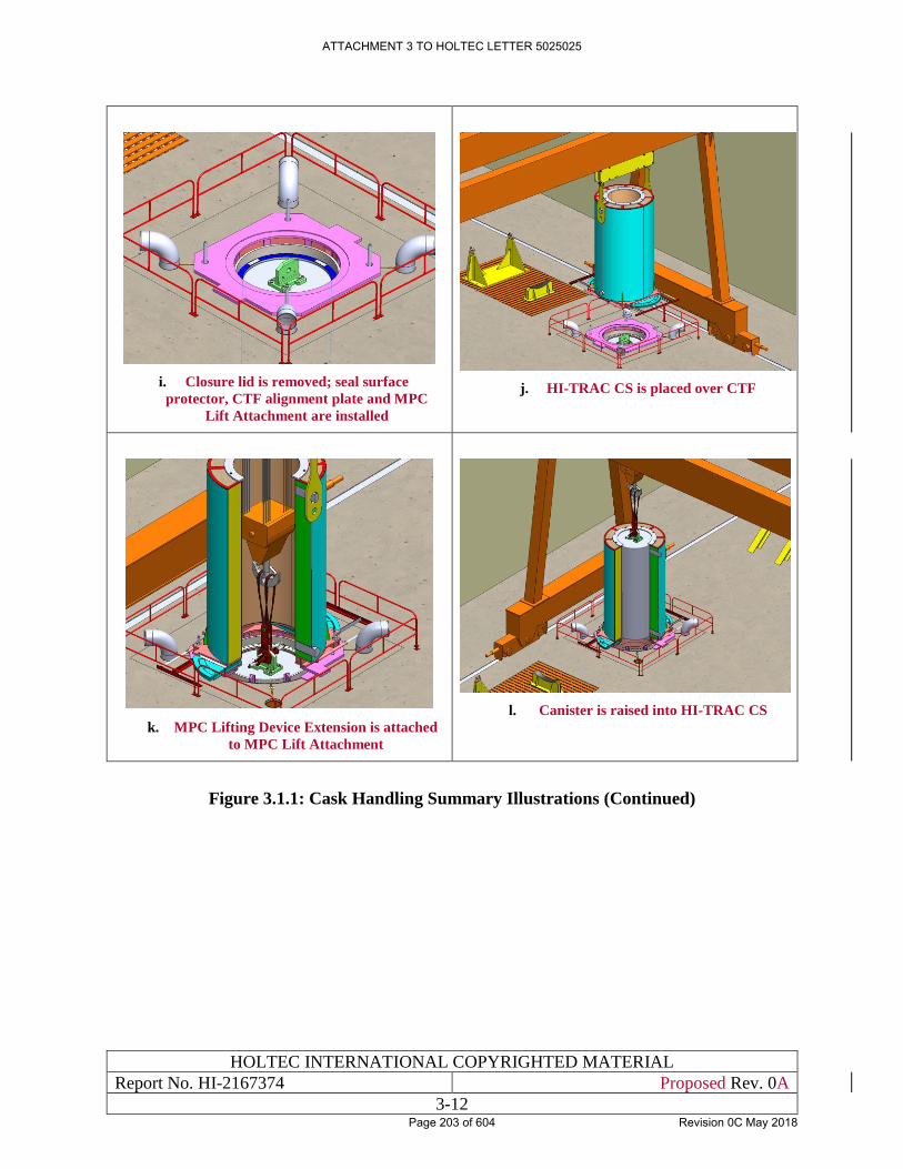
HOLTEC INTERNATIONAL COPYRIGHTED MATERIAL
Report No. HI-2167374 Proposed Rev. 0A
3-12
i. Closure lid is removed; seal surface
protector, CTF alignment plate and MPC
Lift Attachment are installed
j. HI-TRAC CS is placed over CTF
k. MPC Lifting Device Extension is attached
to MPC Lift Attachment
l. Canister is raised into HI-TRAC CS
Figure 3.1.1: Cask Handling Summary Illustrations (Continued)
ATTACHMENT 3 TO HOLTEC LETTER 5025025
Page 203 of 604 Revision 0C May 2018
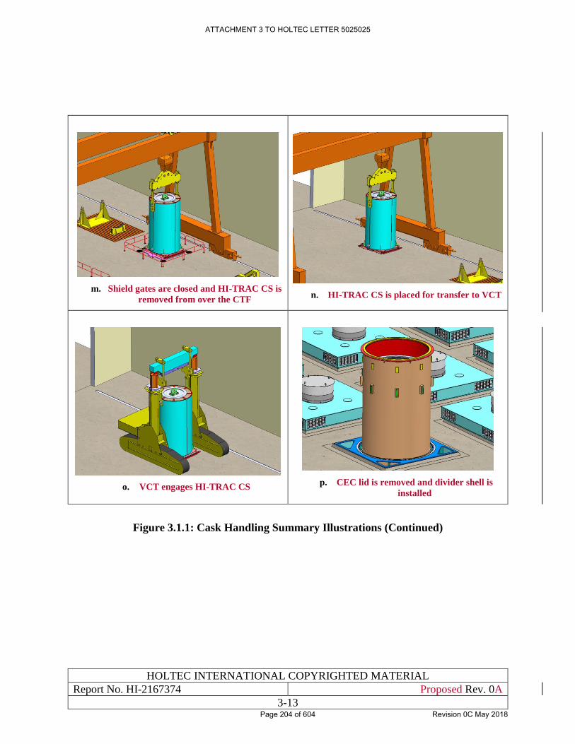
HOLTEC INTERNATIONAL COPYRIGHTED MATERIAL
Report No. HI-2167374 Proposed Rev. 0A
3-13
m. Shield gates are closed and HI-TRAC CS is
removed from over the CTF
n. HI-TRAC CS is placed for transfer to VCT
o. VCT engages HI-TRAC CS
p. CEC lid is removed and divider shell is
installed
Figure 3.1.1: Cask Handling Summary Illustrations (Continued)
ATTACHMENT 3 TO HOLTEC LETTER 5025025
Page 204 of 604 Revision 0C May 2018
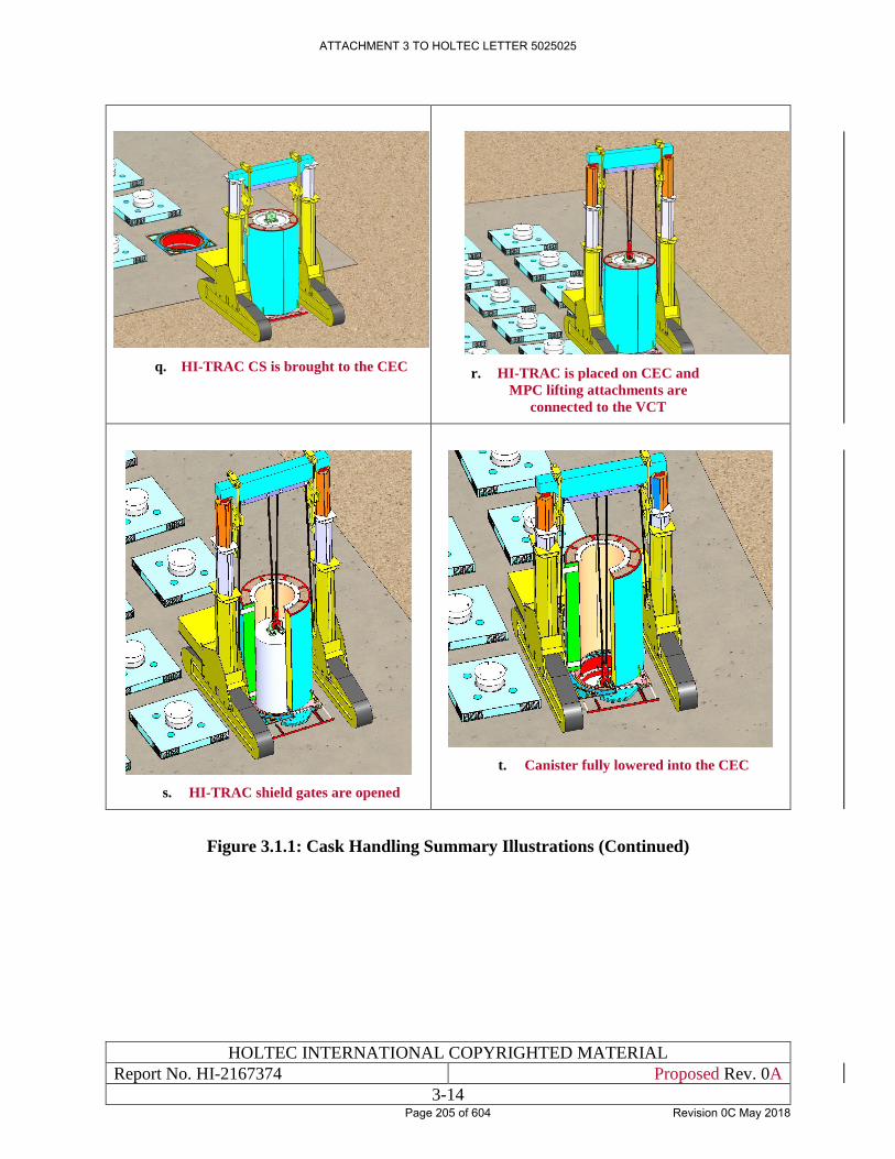
HOLTEC INTERNATIONAL COPYRIGHTED MATERIAL
Report No. HI-2167374 Proposed Rev. 0A
3-14
q. HI-TRAC CS is brought to the CEC
r. HI-TRAC is placed on CEC and
MPC lifting attachments are
connected to the VCT
s. HI-TRAC shield gates are opened
t. Canister fully lowered into the CEC
Figure 3.1.1: Cask Handling Summary Illustrations (Continued)
ATTACHMENT 3 TO HOLTEC LETTER 5025025
Page 205 of 604 Revision 0C May 2018
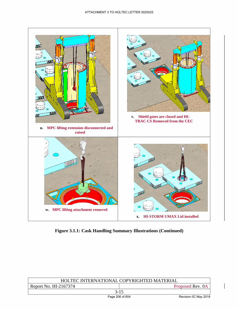
HOLTEC INTERNATIONAL COPYRIGHTED MATERIAL
Report No. HI-2167374 Proposed Rev. 0A
3-15
u. MPC lifting extension disconnected and
raised
v. Shield gates are closed and HI-
TRAC CS Removed from the CEC
w. MPC lifting attachment removed
x. HI-STORM UMAX Lid installed
Figure 3.1.1: Cask Handling Summary Illustrations (Continued)
ATTACHMENT 3 TO HOLTEC LETTER 5025025
Page 206 of 604 Revision 0C May 2018
HOLTEC INTERNATIONAL COPYRIGHTED MATERIAL
Report No. HI-2167374 Proposed Rev. 0A
3-16
Figure 3.1.2: [PROPRIETARY INFORMATION WITHHELD IN ACCORDANCE WITH 10CFR2.390]
ATTACHMENT 3 TO HOLTEC LETTER 5025025
Page 207 of 604 Revision 0C May 2018
HOLTEC INTERNATIONAL COPYRIGHTED MATERIAL
Report No. HI-2167374 Proposed Rev. 0A
3-17
3.2 SPENT FUEL AND HIGH-LEVEL WASTE HANDLING SYSTEMS
3.2.1 Spent Fuel Canister Receipt, Handling, and Transfer
An operational description of the systems used for the receipt and transfer of spent fuel canisters
is provided in the following paragraphs. Special features of these systems to ensure safe handling
of the spent fuel canisters are also described.
3.2.1.1 Spent Fuel Canister Receipt
3.2.1.1.1 Functional Description
The transportation casks and impact limiters comprise the system in which the spent nuclear fuel
canisters are contained when they arrive at HI-STORE. The transportation cask system protects
the enclosed spent fuel canister from physical damage, provides shielding, and allows sufficient
cooling of the canister while in transit to HI-STORE.
3.2.1.1.2 Safety Features
Safety features of the transport system include the impact limiters, which help protect the spent
fuel inside the transportation cask during transportation. Furthermore, the design features of the
transportation cask, which provides gamma and neutron shielding, conductive and radiant cooling,
criticality control, and structural strength to protect the spent fuel canister. A tamper-proof device
on the cask provides indication of an unauthorized attempt to obtain access to the cask. These
safety features are fully described in the HI-STAR transportation cask SAR [1.3.6].
3.2.1.2 Spent Fuel Canister Handling
3.2.1.2.1 Functional Description
The cask handling crane performs handling functions inside the CTB for the transportation cask
and the HI-TRAC CS. The MPC lift attachment and MPC lifting device extension connect to the
overhead crane for MPC lifting and lowering in the CTB.
Cask handling components include the transportation cask and transfer cask, transport cask
horizontal lift beam, lift yokes, tilt frame, VCT, cask handling crane and HI-TRAC CS lift links.
The HI-TRAC CS lift links connect the VCT to the HI-TRAC CS lifting trunnions.
The canister handling components consist of the MPC lift attachment and MPC lifting device
extension.
3.2.1.2.2 Safety Features
Safety features of the cask handling crane include single-failure-proof designs for preventing
uncontrolled lowering of the load upon failure of any single component, limit switches for
prevention of hook travel beyond safe operating positions, and provisions for lowering a load in
the event of an overload trip. The crane is classified as ASME NOG-1 Type 1 [3.0.1]. A Type 1
crane is defined as a crane that is designed and constructed to remain in place and support a critical
load during and after a seismic event and has single-failure proof features such that any credible
failure of a single component will not result in the loss of capability to stop and/or hold the critical
load. Design requirements for the crane include testing, inspection, and maintenance activities in
accordance with 10CFR72.122(f) which, are also performed per the QA Program described in
ATTACHMENT 3 TO HOLTEC LETTER 5025025
Page 208 of 604 Revision 0C May 2018
HOLTEC INTERNATIONAL COPYRIGHTED MATERIAL
Report No. HI-2167374 Proposed Rev. 0A
3-18
Chapter 12. Strict adherence to the design, testing, inspection, and maintenance criteria as noted
above ensure adequate safety margins are provided to prevent damage to the transportation cask,
canister, or storage cask during normal, off-normal, and accident conditions. Discussion on design
criteria and the subsequent evaluations for these SSCs are found in Chapters 4 and 5, respectively.
The crane design include limit switches for prevention of gantry, trolley, and hook travel beyond
safe operating positions, limits on gantry, trolley, and hook travel speeds, and provisions for
lowering a load in the event of an overload trip. Periodic inspection and testing will be performed
to keep the cranes certified to ASME NOG-1 [3.0.1].
Safety features of the HI-TRAC CS handling components include single-failure-proof lift capacity
or equivalent safety factor as described in this SAR.
The loaded HI-TRAC CS is restrained during all aspects of canister handling either by the VCT
and/or the anchor studs or by the wide base of the HI-TRAC CS during switching from the cask
handling crane to the VCT. Evaluation shows that the HI-TRAC CS cannot topple over during an
earthquake.
Safety features associated with the VCT include redundant drop protection systems designed to
withstand drops that could result from a failure associated with the transporter lift components.
The transporter is designed with hydraulic counter-balance valves and anti-drop mechanical
locking mechanisms which automatically engage on the loss of hydraulic pressure. Markings on
the lift boom and an indictor on the operating console give indication of the lifted height. HI-
TRAC CS lifting attachments are designed and tested in accordance with ANSI N14.6 [1.2.4].
The safety features of the canister handling components, slings and MPC lifting attachments, are
their redundancy and the required enhanced stress safety margins as described in the HI-STORM
UMAX FSAR [1.0.6].
3.2.1.3 Spent Fuel Canister Transfer
3.2.1.3.1 Functional Description
The HI-TRAC CS is used for transfer of the spent fuel canister between the transportation cask
and the CEC. The HI-TRAC CS protects the spent fuel canister from physical damage and
provides radiation shielding to personnel.
3.2.1.3.2 Safety Features
The HI-TRAC CS provides radiation shielding when carrying a canister loaded with spent fuel.
The HI-TRAC CS lifting trunnions are designed to the single-failure proof requirements of
NUREG-0612 [1.2.7] so that a load drop event involving the HI-TRAC CS is non-credible.
As described in Subsection 1.2.4, the HI-TRAC CS consists of a radially-connected pair of
concentric steel shells filled with high density concrete. Two lifting trunnions and two rotation
trunnions are provided for HI-TRAC CS handling. The HI-TRAC CS has a pair of thick movable
shield gates at the bottom to allow raising the canister into the transfer cask, lowering of the
canister into the storage or transportation cask, or to support the canister weight and provide
shielding while in the HI-TRAC CS. The shield gates slide in steel guide rails along each side of
the HI-TRAC CS. Steel pins or bolts are used to prevent inadvertent opening of the doors.
The HI-TRAC CS features a top steel ring that prevents the canister from being lifted above the
top of the cask thus insuring that the canister remains within the radiation protected envelope of
ATTACHMENT 3 TO HOLTEC LETTER 5025025
Page 209 of 604 Revision 0C May 2018
HOLTEC INTERNATIONAL COPYRIGHTED MATERIAL
Report No. HI-2167374 Proposed Rev. 0A
3-19
the transfer cask. A lifting yoke provided with the HI-TRAC CS is used to interface with the cask
handling crane. The VCT features lift links which connect the HI-TRAC CS trunnions to the VCT
top beam for handling with the VCT.
3.2.2 Spent Fuel Canister Storage
Spent fuel storage consists of the HI-STORM UMAX storage system, which includes spent fuel
canisters placed in the steel Canister Enclosure Cavity (CEC) below ground in the HI-STORM
UMAX ISFSI. The storage system is entirely passive by design and is completely autonomous
(i.e., it requires no support systems for its operation).
Surveillance of the HI-STORM VVM assembly to ensure its continued effectiveness involves the
following principal activities:
1. Check for intrusion of foreign objects that may impair the system’s thermal performance
during normal operations and in the wake of an extreme environmental phenomenon.
2. Check for corrosion damage to the steel parts, namely the CECs (oldest or most vulnerable
VVM shall be inspected).
3. Check for structural damage to the ISFSI after an earthquake.
4. Perform the heat removal operability surveillance as specified in the Technical
Specifications.
5. Perform ISFSI Security Operations in accordance with the site’s security plan.
Routine maintenance on the HI-STORM UMAX System will typically be limited to cleaning and
touch-up painting of the exposed steel surfaces, repair, and replacement of damaged vent screens,
and removal of vent blockages (e.g., leaves, debris), if any. The heat removal system operability
surveillance should be performed after any event that may have an impact on the safe functioning
of the HI-STORM UMAX system. These include, but are not limited to, wind storms, snow
storms, fire inside the ISFSI, seismic activity, and/or observed animal, bird, or insect infestations.
The responses to these conditions involve first assessing the dose impact to perform the corrective
action (inspect the HI-STORM VVM cavity, clear the debris, check for any structural damage of
the ISFSI pad, and/or replace damaged vent screens); perform the corrective action; and verify that
the system is operable (check ventilation flow paths and radiation blockage capability). In the
unlikely event of significant damage to the ISFSI, possibly from a Beyond-the-Design Basis
earthquake, the situation may warrant removal and visual inspection of the canister, and repair or
replacement of the damaged ISFSI areas.
The storage system performs its functions under normal conditions as discussed in Chapter 10 and
off-normal and accident level conditions as discussed in Chapter 15. Limits of operation
associated with various normal and off-normal conditions are contained in Chapter 16.
Surveillance requirements are also contained in Chapter 16.
3.2.2.1 Safety Features
Safety features include a passive dry storage system design and administrative controls. The
canister is enclosed in the cavity of the HI-STORM UMAX storage system, which protects the
canister from severe natural phenomena (such as tornado-driven missiles), provides required
shielding of the canister, and flow paths for natural convection cooling. Because of its
ATTACHMENT 3 TO HOLTEC LETTER 5025025
Page 210 of 604 Revision 0C May 2018
HOLTEC INTERNATIONAL COPYRIGHTED MATERIAL
Report No. HI-2167374 Proposed Rev. 0A
3-20
underground disposition, the canister stored inside HI-STORM UMAX cannot tip-over. Safety
features are discussed in greater detail in the HI-STORM UMAX FSAR [1.0.6].
ATTACHMENT 3 TO HOLTEC LETTER 5025025
Page 211 of 604 Revision 0C May 2018
HOLTEC INTERNATIONAL COPYRIGHTED MATERIAL
Report No. HI-2167374 Proposed Rev. 0A
3-21
3.3 OTHER OPERATING SYSTEMS
The storage casks are passive and require no other operating systems for safe storage of the spent
fuel once they are placed into storage. The HI-STORE operating systems are described in this
chapter and Chapter 10.
ATTACHMENT 3 TO HOLTEC LETTER 5025025
Page 212 of 604 Revision 0C May 2018
HOLTEC INTERNATIONAL COPYRIGHTED MATERIAL
Report No. HI-2167374 Proposed Rev. 0A
3-22
3.4 OPERATION SUPPORT SYSTEMS
3.4.1 Instrumentation and Control Systems
Regulation 10CFR72.122(i) requires that instrumentation and control systems be provided to
monitor systems that are classified as Important to Safety. The operation of HI-STORE is passive
and self-contained and therefore does not require control systems to ensure the safe operation of
the system. However, temperatures of the air exiting the VVMs may be monitored to provide a
means for assessing thermal performance of the storage casks. The temperature monitors are
equipped with data recorders and alarms located in the Security Building. The temperature
monitors are not required for safety and therefore are not subjected to important to safety criteria.
Radiation monitoring is provided to ensure doses remain ALARA and is discussed in Chapter 11.
Radiation monitoring is not required to support systems that are classified as Important to Safety.
In the event of an earthquake, Holtec will contact the National Earthquake Information Center,
Golden, CO to acquire seismic data for a post-earthquake performance evaluation.
No other instrumentation or control systems are necessary or are utilized. Therefore, the
requirements of 10CFR72.122(i) are satisfied.
3.4.2 System and Component Spares
Spare temperature monitoring devices are maintained at the site. However, these devices are not
required to maintain safe conditions at the HI-STORE facility. No other instrumentation spares
are required.
ATTACHMENT 3 TO HOLTEC LETTER 5025025
Page 213 of 604 Revision 0C May 2018
HOLTEC INTERNATIONAL COPYRIGHTED MATERIAL
Report No. HI-2167374 Proposed Rev. 0A
3-23
3.5 CONTROL ROOM AND CONTROL AREA
Regulation 10 CFR72.122(j) requires the control room or control area to be designed to ensure that
HI-STORE is safely operated, monitored, and controlled for off-normal or accident conditions.
This requirement is not applicable to HI-STORE because the spent fuel storage system is a passive
system and hence does not require a control room to ensure safe operation.
ATTACHMENT 3 TO HOLTEC LETTER 5025025
Page 214 of 604 Revision 0C May 2018
HOLTEC INTERNATIONAL COPYRIGHTED MATERIAL
Report No. HI-2167374 Proposed Rev. 0A
3-24
3.6 ANALYTICAL SAMPLING
No sampling is required for the safe operation of HI-STORE or to ensure that operations are within
prescribed limits. Sampling of the gas inside the transportation cask is performed prior to venting
and opening the cask in the CTB. Evaluation of the gas sample determines if the gas can be
released to the atmosphere or if it must be filtered and the appropriate radiological protection
needed when removing the transportation cask closure. Since the sampling is not required for
nuclear safety of the facility, it is not classified as Important-to-Safety.
ATTACHMENT 3 TO HOLTEC LETTER 5025025
Page 215 of 604 Revision 0C May 2018
HOLTEC INTERNATIONAL COPYRIGHTED MATERIAL
Report No. HI-2167374 Proposed Rev. 0A
3-25
3.7 POOL AND POOL FACILITY SYSTEMS
The HI-STORE facility does not need a pool for storage or transfer operations. Canisters are
received, transferred and stored in the dry condition.
ATTACHMENT 3 TO HOLTEC LETTER 5025025
Page 216 of 604 Revision 0C May 2018
HOLTEC INTERNATIONAL COPYRIGHTED MATERIAL
Report No. HI-2167374 Proposed Rev. 0A
3-26
3.8 REGULATORY COMPLIANCE
The operational steps required to place a loaded canister into a HI-STORM UMAX VVM cavity
have been described in this chapter. The steps to remove a canister from a loaded VVM, which
are essentially reverse of the steps in the loading sequence, have also been provided. These loading
steps are sufficiently detailed to lead to the conclusion that the guidelines of safety and ALARA
set down in NUREG-1567 [1.0.3] are fully satisfied. In particular, it can be concluded that:
i. There are no radiation streaming paths from the canister during its transfer operation.
ii. The handling operations occur near grade level thus eliminating the need for
ladders/platforms and improving the human factors aspects.
iii. There are no exterior freestanding structures in the canister transfer operations and thus
there is no risk of uncontrolled load movement under a (hypothetical) extreme
environmental event such as tornado or high winds.
iv. The ventilation paths to passively cool the canister using ambient air during the transfer
operation is maintained at all times thus protecting the fuel cladding from overheating and
eliminating any thermally guided time limit on the duration for implementing the transfer
steps.
v. All heavy load handling is carried out by handling devices that are equipped with redundant
load drop protection features.
vi. Each storage cavity is independently accessible. Installation or removal of any canister
does not have to contend with other stored canisters.
vii. Because the canister insertion (and withdrawal) occurs in the vertical configuration with
ample lateral clearances, there is no risk of scratching or gouging of the canister’s external
surface (Confinement Boundary). Thus the ASME Section III Class 1 prohibition against
damage to the pressure retaining boundary is maintained.
It is thus concluded that the HI-STORM UMAX ISFSI is engineered to meet the safety and
ALARA imperatives contemplated in 10CFR72 [1.0.5] in full measures.
ATTACHMENT 3 TO HOLTEC LETTER 5025025
Page 217 of 604 Revision 0C May 2018
HOLTEC INTERNATIONAL COPYRIGHTED MATERIAL
Report No. HI-2167374 Proposed Rev. 0C
4-1
CHAPTER 4: DESIGN CRITERIA FOR THE HI-STORE CIS
SYSTEMS, STRUCTURES AND COMPONENTS
4.0 INTRODUCTION
This chapter contains safety-relevant information on the HI-STORE CIS facility in the following
topical areas:
a. Spent fuel or other high-level radioactive waste containers (canisters) authorized to be
stored,
b. Classification of structures, systems and components (SSCs) according to their importance
–to-safety, and
c. Design criteria and design bases for the HI-STORE CIS facility and associated SSCs during
all operational modes, including normal and off-normal operations, Short Term
Operations, accident conditions and extreme natural phenomena events.
Unlike the generic HI-STORM UMAX system, the Short-Term Operations at the HI-STORE
facility do not involve any activity related to loading fuel into canisters: the canisters arrive at the
HI-STORE CIS facility in a NRC-certified transport cask such as HI-STAR 190 (NRC docket #
71-9373). The Short Term Operations begin at the point the transport package is received at the
site and end at the point the canister is placed in a HI-STORM VVM for interim storage.
As stated in Chapter 1, the HI-STORM UMAX system (NRC Docket # 72-1040) [1.0.6] is the sole
storage system designated to be employed at the HI-STORE CIS facility. As the canisters certified
for use in the HI-STORM UMAX system are qualified in the HI-STORM FW system (NRC
Docket # 72-1032) [1.3.7], there is a direct nexus between the site specific safety analyses for HI-
STORE CIS facility and the analyses that undergird the general certification in [1.0.6] and [1.3.7].
As documented in this chapter, the loadings and conditions for which the HI-STORM UMAX
VVM and its canisters are certified in [1.0.6] substantially exceed their counterparts for the HI-
STORE CIS facility. This safety analysis reports mandates that only those canisters that are
authorized for storage in HI-STORM UMAX under its general certification can be stored at the
HI-STORE CIS facility. Furthermore, even among the population of canisters authorized by the
HI-STORM UMAX CoC, only those that meet the heat load limit of the transport cask can be
transported to the site will be available for storage at the site. Because the transport cask has a
much lower heat load capacity than the HI-STORM UMAX ventilated storage system, the
limitation imposed by the transport cask winnows the number of canisters eligible for storage at
the HI-STORE CIS facility significantly. It is evident that those canisters that meet the heat load
limitation of the transport cask, because of the greater innate heat rejection capacity of ventilated
systems, will be subject to a less severe thermal state at the HI-STORE CIS facility than that
permitted under ISG-11 Rev. 3 [4.0.1] under long term storage.
The HI-STORE facility must be qualified to withstand all credible environmental or operation-
related loadings without exceeding its applicable safety limits. To make this safety determination,
All references are placed within square brackets in this report and are compiled in Chapter 19 of this report.
ATTACHMENT 3 TO HOLTEC LETTER 5025025
Page 218 of 604 Revision 0C May 2018
HOLTEC INTERNATIONAL COPYRIGHTED MATERIAL
Report No. HI-2167374 Proposed Rev. 0C
4-2
the credible loadings under all normal, off-normal and faulted states are compared with those that
have been qualified in the HI-STORM UMAX FSAR [1.0.6]. Any load that is found to exceed the
pre-certified limit in the HI-STORM UMAX FSAR [1.0.6] is so identified in this chapter for
further analysis.
As noted subsequently in this chapter, the site specific environmental and accident loads are fewer
in number and less severe than those treated in the HI-STORM UMAX FSAR [1.0.6]. This
statement applies to the Design Basis Earthquake (DBE) also where the 10,000-year return
earthquake is shown to be bounded by the DBE for which the HI-STORM UMAX system is pre-
certified. Much of the safety analysis material in this chapter pertains to confirming that each HI-
STORE site specific loading is bounded by its counterpart treated in the HI-STORM UMAX
FSAR.
Many of the Design Criteria pertaining to the loadings and components common to the HI-STORM
UMAX and the HI-STORE CIS systems, such as the MPC and VVM, are incorporated by
reference in this SAR, as appropriate, to the HI-STORM UMAX FSAR [1.0.6]. To facilitate
convenient access to the referenced material, a list of HI-STORM UMAX FSAR sections germane
to this chapter is provided in Table 4.0.1.
ATTACHMENT 3 TO HOLTEC LETTER 5025025
Page 219 of 604 Revision 0C May 2018
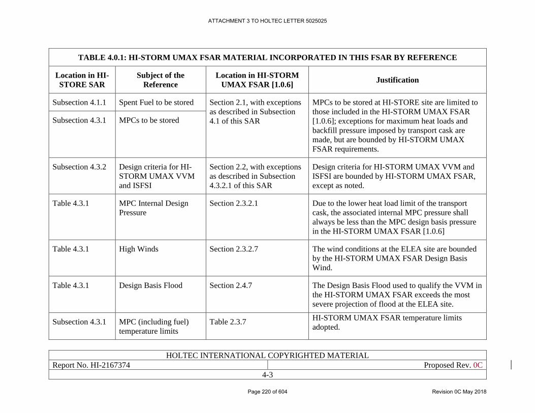
HOLTEC INTERNATIONAL COPYRIGHTED MATERIAL
Report No. HI-2167374 Proposed Rev. 0C
4-3
TABLE 4.0.1: HI-STORM UMAX FSAR MATERIAL INCORPORATED IN THIS FSAR BY REFERENCE
Location in HI-
STORE SAR
Subject of the
Reference
Location in HI-STORM
UMAX FSAR [1.0.6] Justification
Subsection 4.1.1 Spent Fuel to be stored Section 2.1, with exceptions
as described in Subsection
4.1 of this SAR
MPCs to be stored at HI-STORE site are limited to
those included in the HI-STORM UMAX FSAR
[1.0.6]; exceptions for maximum heat loads and
backfill pressure imposed by transport cask are
made, but are bounded by HI-STORM UMAX
FSAR requirements.
Subsection 4.3.1 MPCs to be stored
Subsection 4.3.2 Design criteria for HI-
STORM UMAX VVM
and ISFSI
Section 2.2, with exceptions
as described in Subsection
4.3.2.1 of this SAR
Design criteria for HI-STORM UMAX VVM and
ISFSI are bounded by HI-STORM UMAX FSAR,
except as noted.
Table 4.3.1 MPC Internal Design
Pressure
Section 2.3.2.1 Due to the lower heat load limit of the transport
cask, the associated internal MPC pressure shall
always be less than the MPC design basis pressure
in the HI-STORM UMAX FSAR [1.0.6]
Table 4.3.1 High Winds Section 2.3.2.7 The wind conditions at the ELEA site are bounded
by the HI-STORM UMAX FSAR Design Basis
Wind.
Table 4.3.1 Design Basis Flood Section 2.4.7 The Design Basis Flood used to qualify the VVM in
the HI-STORM UMAX FSAR exceeds the most
severe projection of flood at the ELEA site.
Subsection 4.3.1 MPC (including fuel)
temperature limits
Table 2.3.7 HI-STORM UMAX FSAR temperature limits
adopted.
ATTACHMENT 3 TO HOLTEC LETTER 5025025
Page 220 of 604 Revision 0C May 2018
HOLTEC INTERNATIONAL COPYRIGHTED MATERIAL
Report No. HI-2167374 Proposed Rev. 0C
4-4
Subsection 4.3.2 VVM temperature limits Table 2.3.7 HI-STORM UMAX FSAR temperature limits
adopted.
ATTACHMENT 3 TO HOLTEC LETTER 5025025
Page 221 of 604 Revision 0C May 2018
HOLTEC INTERNATIONAL COPYRIGHTED MATERIAL
Report No. HI-2167374 Proposed Rev. 0C
4-5
4.1 MATERIALS TO BE STORED
4.1.1 Spent Fuel Canisters
The SNF-bearing canisters that will be stored at the HI-STORE CIS facility are limited to those
included in the HI-STORM UMAX FSAR [1.0.6]. No canister that is not included in the HI-
STORM UMAX FSAR can be stored at the HI-STORE CIS Facility. Therefore all canisters (and
the SNF specified as acceptable for storage in said canisters) to be stored at the facility are
incorporated by reference herein, as follows:
• Authorized contents are incorporated by reference from Section 2.1 of the HI-STORM
UMAX FSAR [1.0.6], with the following exceptions:
i. Maximum permissible heat loads specified in Subsection 2.1.9 of the HI-STORM
UMAX FSAR [1.0.6], are replaced by more restrictive heat load imposed by the
transport cask heat load requirements;
ii. The helium backfill pressure options of Tables 2.1.8 and 2.1.9 of the HI-STORM
UMAX FSAR [1.0.6], which relate to the establishment of the permissible aggregrate
heat load, are supplanted by the requirements of this chapter.
Canisters to be stored at the HI-STORE CIS Facility must meet the maximum heat loads shown in
Tables 4.1.1 and 4.1.2 of this SAR, in accordance with the regional loading patterns shown in
Figures 4.1.1 and 4.1.2 of this SAR (item i).
Requirements for the helium backfill of all canisters to be stored at the HI-STORE CIS are in Table
4.1.3 and 4.1.4 of this SAR (item ii). Although canisters will not be backfilled at site, received
canisters will be verified to meet these helium backfill requirements as a condition of acceptance.
4.1.2 High Level Radioactive Waste
This SAR does not consider safety analysis of any canister that is not certified in the HI-STORM
UMAX docket [1.0.6]. Accordingly, it does not at the present time include any canister containing
non-fissile High Level Radioactive Waste at the HI-STORE CIS facility.
ATTACHMENT 3 TO HOLTEC LETTER 5025025
Page 222 of 604 Revision 0C May 2018
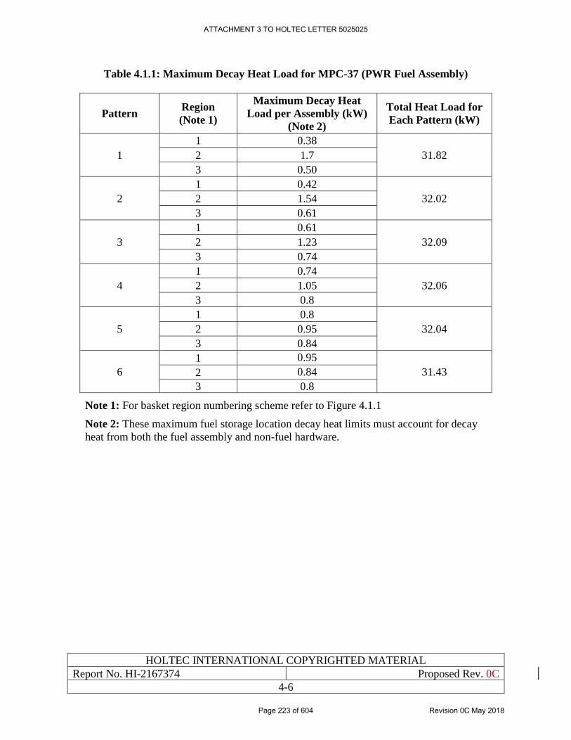
HOLTEC INTERNATIONAL COPYRIGHTED MATERIAL
Report No. HI-2167374 Proposed Rev. 0C
4-6
Table 4.1.1: Maximum Decay Heat Load for MPC-37 (PWR Fuel Assembly)
Pattern Region
(Note 1)
Maximum Decay Heat
Load per Assembly (kW)
(Note 2)
Total Heat Load for
Each Pattern (kW)
1
1 0.38
31.82 2 1.7
3 0.50
2
1 0.42
32.02 2 1.54
3 0.61
3
1 0.61
32.09 2 1.23
3 0.74
4
1 0.74
32.06 2 1.05
3 0.8
5
1 0.8
32.04 2 0.95
3 0.84
6
1 0.95
31.43 2 0.84
3 0.8
Note 1: For basket region numbering scheme refer to Figure 4.1.1
Note 2: These maximum fuel storage location decay heat limits must account for decay
heat from both the fuel assembly and non-fuel hardware.
ATTACHMENT 3 TO HOLTEC LETTER 5025025
Page 223 of 604 Revision 0C May 2018
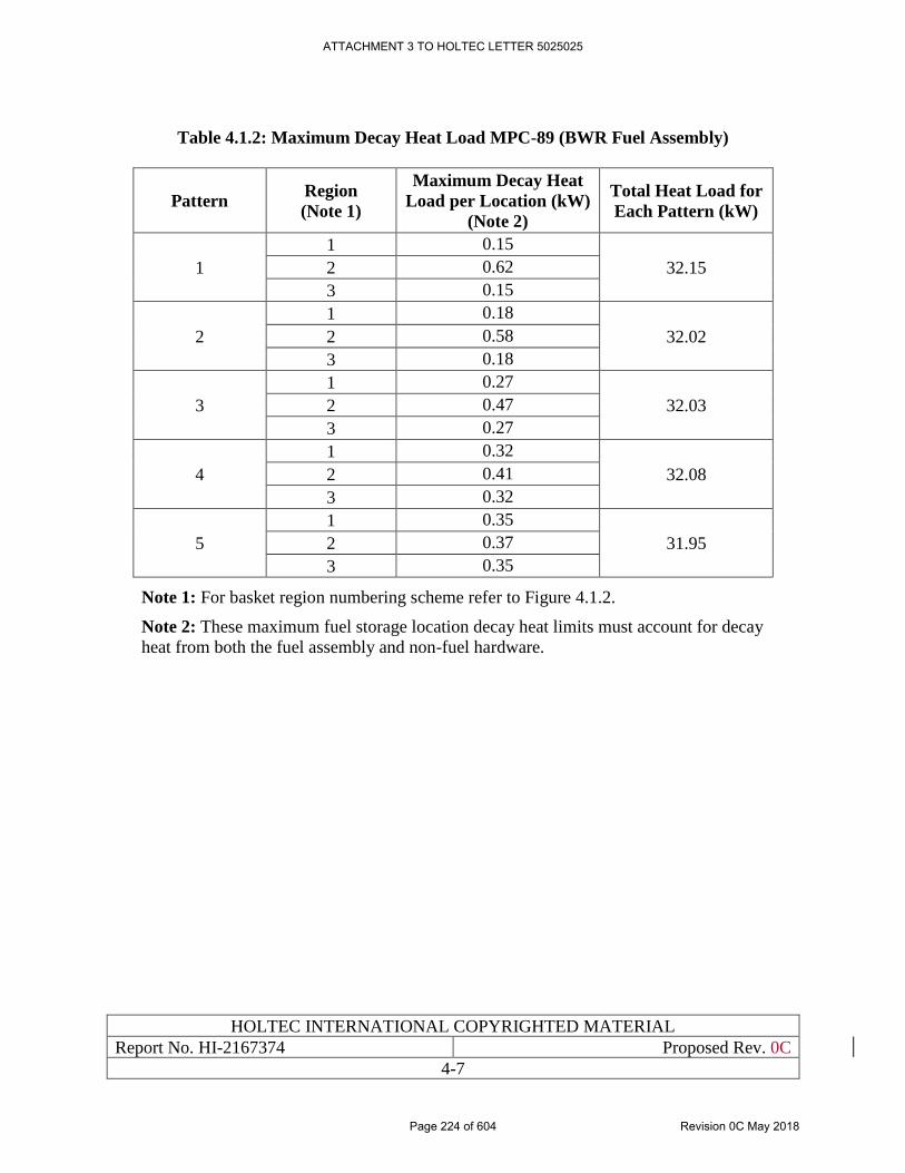
HOLTEC INTERNATIONAL COPYRIGHTED MATERIAL
Report No. HI-2167374 Proposed Rev. 0C
4-7
Table 4.1.2: Maximum Decay Heat Load MPC-89 (BWR Fuel Assembly)
Pattern Region
(Note 1)
Maximum Decay Heat
Load per Location (kW)
(Note 2)
Total Heat Load for
Each Pattern (kW)
1
1 0.15
32.15 2 0.62
3 0.15
2
1 0.18
32.02 2 0.58
3 0.18
3
1 0.27
32.03 2 0.47
3 0.27
4
1 0.32
32.08 2 0.41
3 0.32
5
1 0.35
31.95 2 0.37
3 0.35
Note 1: For basket region numbering scheme refer to Figure 4.1.2.
Note 2: These maximum fuel storage location decay heat limits must account for decay
heat from both the fuel assembly and non-fuel hardware.
ATTACHMENT 3 TO HOLTEC LETTER 5025025
Page 224 of 604 Revision 0C May 2018
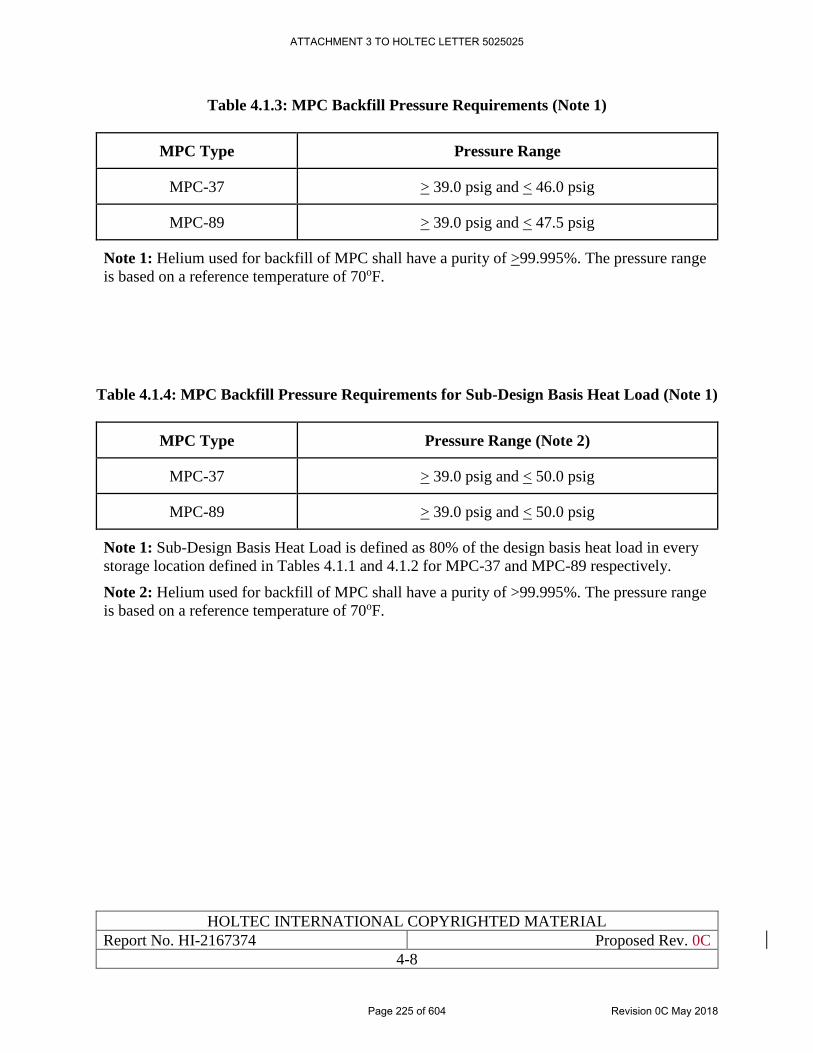
HOLTEC INTERNATIONAL COPYRIGHTED MATERIAL
Report No. HI-2167374 Proposed Rev. 0C
4-8
Table 4.1.3: MPC Backfill Pressure Requirements (Note 1)
MPC Type Pressure Range
MPC-37 > 39.0 psig and < 46.0 psig
MPC-89 > 39.0 psig and < 47.5 psig
Note 1: Helium used for backfill of MPC shall have a purity of >99.995%. The pressure range
is based on a reference temperature of 70oF.
Table 4.1.4: MPC Backfill Pressure Requirements for Sub-Design Basis Heat Load (Note 1)
MPC Type Pressure Range (Note 2)
MPC-37 > 39.0 psig and < 50.0 psig
MPC-89 > 39.0 psig and < 50.0 psig
Note 1: Sub-Design Basis Heat Load is defined as 80% of the design basis heat load in every
storage location defined in Tables 4.1.1 and 4.1.2 for MPC-37 and MPC-89 respectively.
Note 2: Helium used for backfill of MPC shall have a purity of >99.995%. The pressure range
is based on a reference temperature of 70oF.
ATTACHMENT 3 TO HOLTEC LETTER 5025025
Page 225 of 604 Revision 0C May 2018
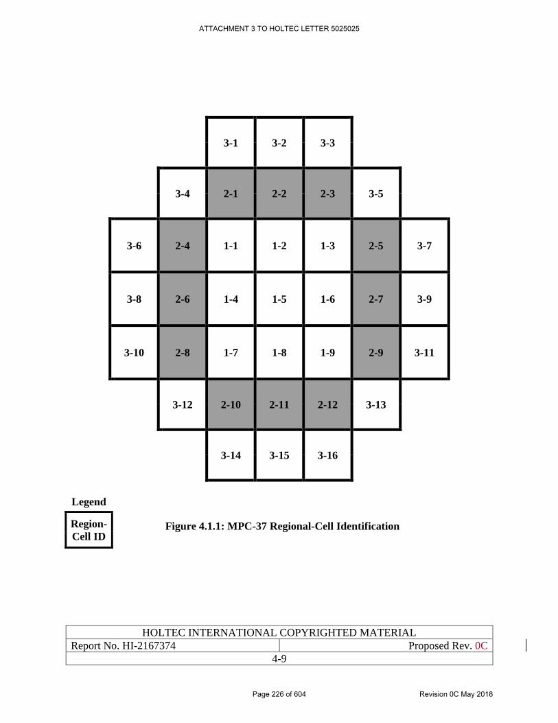
HOLTEC INTERNATIONAL COPYRIGHTED MATERIAL
Report No. HI-2167374 Proposed Rev. 0C
4-9
3-1 3-2 3-3
3-4 2-1 2-2 2-3 3-5
3-6 2-4 1-1 1-2 1-3 2-5 3-7
3-8 2-6 1-4 1-5 1-6 2-7 3-9
3-10 2-8 1-7 1-8 1-9 2-9 3-11
3-12 2-10 2-11 2-12 3-13
3-14 3-15 3-16
Figure 4.1.1: MPC-37 Regional-Cell Identification
Legend
Region-
Cell ID
ATTACHMENT 3 TO HOLTEC LETTER 5025025
Page 226 of 604 Revision 0C May 2018
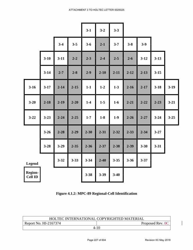
HOLTEC INTERNATIONAL COPYRIGHTED MATERIAL
Report No. HI-2167374 Proposed Rev. 0C
4-10
3-1 3-2 3-3
3-4 3-5 3-6 2-1 3-7 3-8 3-9
3-10 3-11 2-2 2-3 2-4 2-5 2-6 3-12 3-13
3-14 2-7 2-8 2-9 2-10 2-11 2-12 2-13 3-15
3-16 3-17 2-14 2-15 1-1 1-2 1-3 2-16 2-17 3-18 3-19
3-20 2-18 2-19 2-20 1-4 1-5 1-6 2-21 2-22 2-23 3-21
3-22 3-23 2-24 2-25 1-7 1-8 1-9 2-26 2-27 3-24 3-25
3-26 2-28 2-29 2-30 2-31 2-32 2-33 2-34 3-27
3-28 3-29 2-35 2-36 2-37 2-38 2-39 3-30 3-31
3-32 3-33 3-34 2-40 3-35 3-36 3-37
Legend
Region-
Cell ID
3-38 3-39 3-40
Figure 4.1.2: MPC-89 Regional-Cell Identification
ATTACHMENT 3 TO HOLTEC LETTER 5025025
Page 227 of 604 Revision 0C May 2018
HOLTEC INTERNATIONAL COPYRIGHTED MATERIAL
Report No. HI-2167374 Proposed Rev. 0C
4-11
4.2 CLASSIFICATION OF STRUCTURES, SYSTEMS, AND
COMPONENTS
The systems, structures and components (SSCs) for the HI-STORE CIS facility are designed and
analyzed to ensure that they will perform their intended functions under normal, off-normal, and
accident conditions to meet all regulatory requirements delineated in 10 CFR Part 72 [1.0.5]. These
intended functions include:
i. Providing radionuclide confinement/containment
ii. Enabling heat rejection from cask components and contents to maintain their temperatures
within specified regulatory limits
iii. Attenuating emission of radiation to acceptable levels
iv. Maintaining sub-criticality of fissile contents
References [4.2.1] & [4.2.2] provide the guidelines to determine the Important to Safety
significance category in accordance with NUREG/CR-6407 [1.2.2] which are:
Category A: The failure or malfunction of a structure, component, or system could directly
result in a condition adversely affecting public health and safety.
Category B: The failure or malfunction of a structure, component, or system could
indirectly (i.e., in conjunction with the failure of another item) result in a condition
adversely affecting public health and safety.
Category C: The failure or malfunction of a system, structure or component (SSC) that
would have some effect on the packaging, but would not significantly reduce the
effectiveness of the packaging and would not be likely to create a situation adversely
affecting public health and safety.
Not-Important-to-Safety: The failure or malfunction of an SSC would not reduce the
effectiveness of the system or packaging and would not create a situation adversely
affecting public health and safety.
Thus each SSC that constitutes the HI-STORE CIS facility is classified into one of above four
categories depending on the severity of consequence in the event of its failure or malfunction due
to a credible adverse event.
Chapter 1 contains the description of the SSCs that comprise the HI-STORE CIS facility. The
SSCs in Table 4.2.1 can be subdivided in two types, namely
i. Those that are designed and built to meet the requirements of the HI-STORE CIS facility
or are assembled at the site (HI-STORE Specific or “HS”)
ii. Those that are pre-qualified and delivered to the site pursuant to the safety requirements in
the HI-STORM UMAX docket and arrive at the site ready-for-deployment (UMAX
Generic or “UG”)
ATTACHMENT 3 TO HOLTEC LETTER 5025025
Page 228 of 604 Revision 0C May 2018
HOLTEC INTERNATIONAL COPYRIGHTED MATERIAL
Report No. HI-2167374 Proposed Rev. 0C
4-12
The ITS category for UG SSCs is defined by their classification in their native docket, principally
the HI-STORM UMAX docket [1.0.6]. Those SSCs whose safety classification is not defined in
other dockets (HS SSCs) are classified using [4.2.1] & [4.2.2]. Table 4.2.1 provides a compilation
of the ITS classification information on all of the principal SSCs that are envisaged to be used at
the HI-STORE CIS facility including both the “HS” and “UG” types; the latter directly excerpted
from the HI-STORM UMAX FSAR [1.0.6] or a referenced docket therein, such as HI-STORM
100 FSAR [1.3.3].
ATTACHMENT 3 TO HOLTEC LETTER 5025025
Page 229 of 604 Revision 0C May 2018
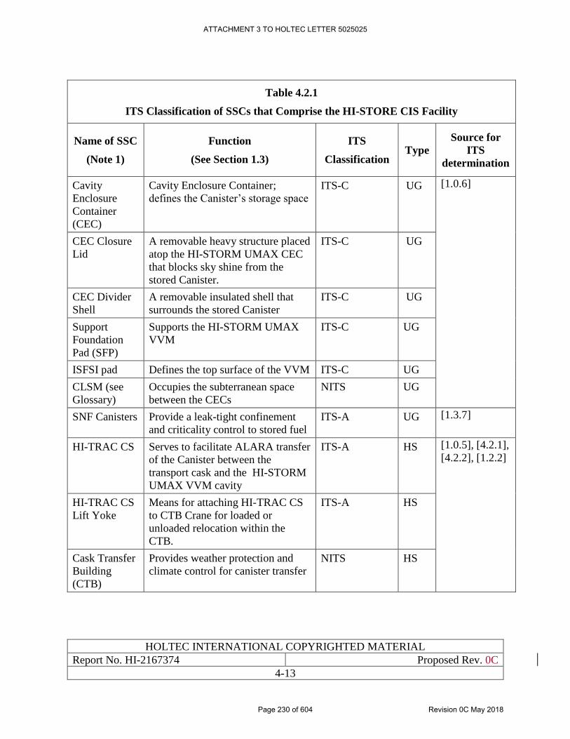
HOLTEC INTERNATIONAL COPYRIGHTED MATERIAL
Report No. HI-2167374 Proposed Rev. 0C
4-13
Table 4.2.1
ITS Classification of SSCs that Comprise the HI-STORE CIS Facility
Name of SSC
(Note 1)
Function
(See Section 1.3)
ITS
Classification Type
Source for
ITS
determination
Cavity
Enclosure
Container
(CEC)
Cavity Enclosure Container;
defines the Canister’s storage space
ITS-C UG [1.0.6]
CEC Closure
Lid
A removable heavy structure placed
atop the HI-STORM UMAX CEC
that blocks sky shine from the
stored Canister.
ITS-C UG
CEC Divider
Shell
A removable insulated shell that
surrounds the stored Canister
ITS-C UG
Support
Foundation
Pad (SFP)
Supports the HI-STORM UMAX
VVM
ITS-C UG
ISFSI pad Defines the top surface of the VVM ITS-C UG
CLSM (see
Glossary)
Occupies the subterranean space
between the CECs
NITS UG
SNF Canisters Provide a leak-tight confinement
and criticality control to stored fuel
ITS-A UG [1.3.7]
HI-TRAC CS Serves to facilitate ALARA transfer
of the Canister between the
transport cask and the HI-STORM
UMAX VVM cavity
ITS-A HS [1.0.5], [4.2.1],
[4.2.2], [1.2.2]
HI-TRAC CS
Lift Yoke
Means for attaching HI-TRAC CS
to CTB Crane for loaded or
unloaded relocation within the
CTB.
ITS-A HS
Cask Transfer
Building
(CTB)
Provides weather protection and
climate control for canister transfer
NITS HS
ATTACHMENT 3 TO HOLTEC LETTER 5025025
Page 230 of 604 Revision 0C May 2018
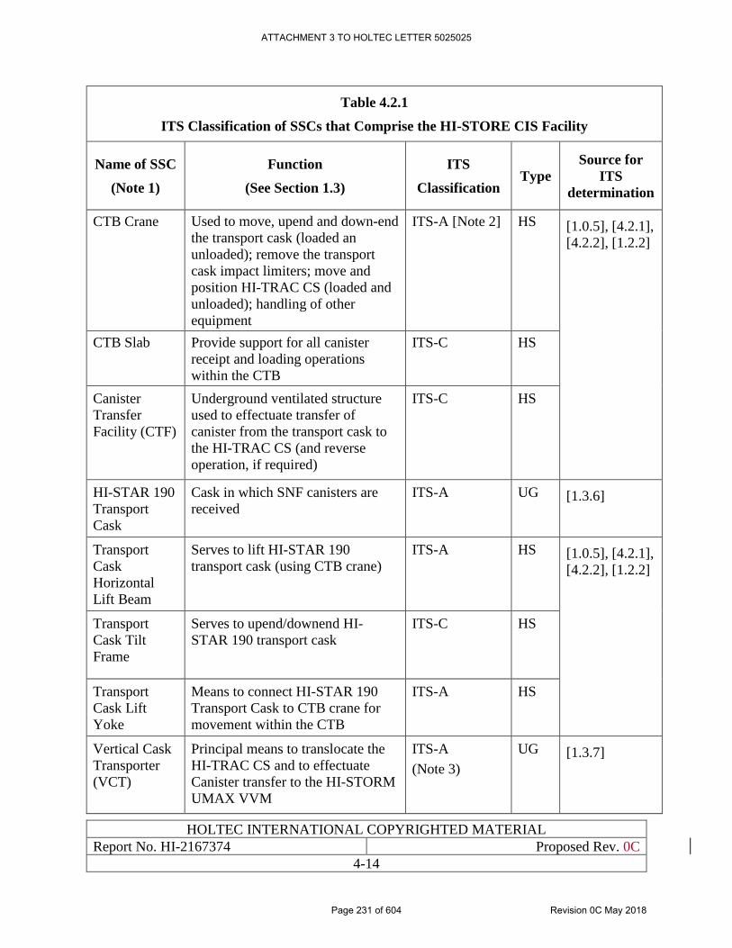
HOLTEC INTERNATIONAL COPYRIGHTED MATERIAL
Report No. HI-2167374 Proposed Rev. 0C
4-14
Table 4.2.1
ITS Classification of SSCs that Comprise the HI-STORE CIS Facility
Name of SSC
(Note 1)
Function
(See Section 1.3)
ITS
Classification Type
Source for
ITS
determination
CTB Crane Used to move, upend and down-end
the transport cask (loaded an
unloaded); remove the transport
cask impact limiters; move and
position HI-TRAC CS (loaded and
unloaded); handling of other
equipment
ITS-A [Note 2] HS [1.0.5], [4.2.1],
[4.2.2], [1.2.2]
CTB Slab Provide support for all canister
receipt and loading operations
within the CTB
ITS-C HS
Canister
Transfer
Facility (CTF)
Underground ventilated structure
used to effectuate transfer of
canister from the transport cask to
the HI-TRAC CS (and reverse
operation, if required)
ITS-C
HS
HI-STAR 190
Transport
Cask
Cask in which SNF canisters are
received
ITS-A UG [1.3.6]
Transport
Cask
Horizontal
Lift Beam
Serves to lift HI-STAR 190
transport cask (using CTB crane)
ITS-A HS [1.0.5], [4.2.1],
[4.2.2], [1.2.2]
Transport
Cask Tilt
Frame
Serves to upend/downend HI-
STAR 190 transport cask
ITS-C HS
Transport
Cask Lift
Yoke
Means to connect HI-STAR 190
Transport Cask to CTB crane for
movement within the CTB
ITS-A HS
Vertical Cask
Transporter
(VCT)
Principal means to translocate the
HI-TRAC CS and to effectuate
Canister transfer to the HI-STORM
UMAX VVM
ITS-A
(Note 3)
UG [1.3.7]
ATTACHMENT 3 TO HOLTEC LETTER 5025025
Page 231 of 604 Revision 0C May 2018
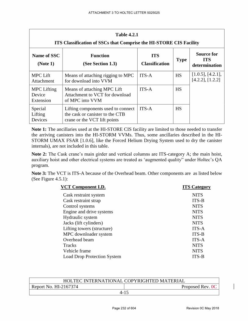
HOLTEC INTERNATIONAL COPYRIGHTED MATERIAL
Report No. HI-2167374 Proposed Rev. 0C
4-15
Table 4.2.1
ITS Classification of SSCs that Comprise the HI-STORE CIS Facility
Name of SSC
(Note 1)
Function
(See Section 1.3)
ITS
Classification Type
Source for
ITS
determination
MPC Lift
Attachment
Means of attaching rigging to MPC
for download into VVM
ITS-A HS [1.0.5], [4.2.1],
[4.2.2], [1.2.2]
MPC Lifting
Device
Extension
Means of attaching MPC Lift
Attachment to VCT for download
of MPC into VVM
ITS-A HS
Special
Lifting
Devices
Lifting components used to connect
the cask or canister to the CTB
crane or the VCT lift points
ITS-A HS
Note 1: The ancillaries used at the HI-STORE CIS facility are limited to those needed to transfer
the arriving canisters into the HI-STORM VVMs. Thus, some ancillaries described in the HI-
STORM UMAX FSAR [1.0.6], like the Forced Helium Drying System used to dry the canister
internals), are not included in this table.
Note 2: The Cask crane’s main girder and vertical columns are ITS-category A; the main hoist,
auxiliary hoist and other electrical systems are treated as ‘augmented quality” under Holtec’s QA
program.
Note 3: The VCT is ITS-A because of the Overhead beam. Other components are as listed below
(See Figure 4.5.1):
VCT Component I.D. ITS Category
Cask restraint system NITS
Cask restraint strap ITS-B
Control systems NITS
Engine and drive systems NITS
Hydraulic system NITS
Jacks (lift cylinders) NITS
Lifting towers (structure) ITS-A
MPC downloader system ITS-B
Overhead beam ITS-A
Tracks NITS
Vehicle frame NITS
Load Drop Protection System ITS-B
ATTACHMENT 3 TO HOLTEC LETTER 5025025
Page 232 of 604 Revision 0C May 2018
HOLTEC INTERNATIONAL COPYRIGHTED MATERIAL
Report No. HI-2167374 Proposed Rev. 0C
4-16
4.3 DESIGN CRITERIA FOR SSCS IMPORTANT TO SAFETY
4.3.1 Multi-Purpose Canisters (MPCs)
The MPCs that will be stored at the HI-STORE CIS are limited to those included in the HI-STORM
UMAX FSAR [1.0.6].
4.3.1.1 Structural
The MPCs to be received and loaded at the HI-STORE CIS facility are comprised of a fuel basket
within a welded enclosure vessel. As the only canisters certified for storage in the HI-STORE CIS
facility are those qualified in the HI-STORM UMAX FSAR [1.0.6], the structural design criteria
for the MPCs is incorporated by reference to Section 2.0.2 of [1.0.6].
4.3.1.2 Thermal
The thermal design criteria for the MPCs (including the design temperature limits of Table 2.3.7)
are incorporated by reference from Section 2.0.3 (MPC Design Criteria), of the HI-STORM
UMAX FSAR [1.0.6]. The portion of Section 2.0.3 of Reference [1.0.6] related to maximum
permissible heat loads and helium backfill is not incorporated by reference, as it has been replaced
with the information presented in Section 4.1.1 of this SAR.
4.3.1.3 Shielding
The site boundary dose requirement for the systems (including canisters) stored at HI-STORE is
provided in Section 4.4. Compliance to the requirements (see Table 4.4.3) is demonstrated in
Chapter 11.
4.3.1.4 Confinement
The MPC provides for confinement of all radioactive materials for all design basis, off-normal and
postulated accident conditions. As the only canisters certified for storage in the HI-STORE CIS
facility are those qualified in the HI-STORM UMAX FSAR [1.0.6], the confinement criteria for
the MPCs is incorporated by reference from Section 2.0.6 of [1.0.6].
4.3.1.5 Criticality Control
Criticality control is maintained by the geometric spacing of the fuel assembles and the spatially
distributed B-10 isotope in the Metamic-HT basket within the canister. As the only canisters
certified for storage in the HI-STORE CIS facility are those qualified in the HI-STORM UMAX
FSAR [1.0.6], the criticality control criteria for the MPCs is incorporated by reference to Section
2.0.5 of [1.0.6].
4.3.2 VVM Components and ISFSI Structures
The design criteria of the HI-STORM UMAX VVM components and ISFSI structures described
in Chapter 2 of the HI-STORM UMAX FSAR [1.0.6] are largely applicable to the HI-STORE
CIS. The criteria of [1.0.6] that bound the HI-STORE CIS design, and are therefore excluded from
ATTACHMENT 3 TO HOLTEC LETTER 5025025
Page 233 of 604 Revision 0C May 2018
HOLTEC INTERNATIONAL COPYRIGHTED MATERIAL
Report No. HI-2167374 Proposed Rev. 0C
4-17
further consideration in this SAR, are outlined in Table 4.3.1. Environmental conditions and
constraints that differ from those bounded by [1.0.6], although minor in nature, are described in
Table 4.3.2 and evaluated herein. With the following exceptions, all subsections of the HI-STORM
UMAX FSAR are relevant to the HI-STORE CIS evaluation:
1 Criteria related to the HI-TRAC VW system. The HI-TRAC VW system is supplanted by
the HI-TRAC CS system in this application, with the design criteria for the HI-TRAC CS
system described herein.
2 Service conditions related to the used of Forced Helium Drying (FHD) described in
Paragraph 2.3.3.5 of the HI-STORM UMAX FSAR. As the HI-STORE CIS facility accepts
only pre-packaged canisters, operations related to internal canister drying are not
applicable.
Information consistent with the regulatory requirements related to shielding, thermal performance,
confinement, radiological, and operational considerations is also provided. The licensing drawing
of the HI-STORM UMAX design variant used in the HI-STORE CIS application is included in
Section 1.5 of this SAR. The licensing drawing provides information on the necessary critical
characteristics that define the HI-STORE CIS UMAX system for this application.
4.3.2.1 Structural
The applicable loads, affected parts under each loading condition, and the applicable structural
acceptance criteria related to the HI-STORM UMAX VVM and ISFSI structures that are compiled
in Section 2.0 of [1.0.6] provide a complete framework for the required qualifying safety analyses
in this SAR. The VVM storage system at the HI-STORE CIS ISFSI will be functionally identical
to that certified in the HI-STORM UMAX docket. The conservative approach of basing the HI-
STORE CIS design on the certified HI-STORM UMAX design is supported by the following:
1. The subgrade and under-grade soil properties at the HI-STORE CIS site are uniformly
better than those assumed for the general certification of the HI-STORM UMAX system.
These properties can be found in the geotechnical investigation completed December 2017
[2.1.24]. HI-STORE Bearing Capacity and Settlement Calculation report HI-2188143
[4.3.5] details the methodology used to compute the bearing capacity at the site. This
calculation confirms the required bearing capacity is met for the soil underneath the
planned construction.
2. The top-of-pad earthquake spectra corresponding to a 10,000-year earthquake at the HI-
STORE CIS site is enveloped by that assumed for the HI-STORM UMAX in its general
certification. (Subsection 4.3.6 and Table 4.3.3 provide a summary of the applicable
seismic loadings for the HI-STORE CIS facility).
3. The long-term settlement at the HI-STORE CIS ISFSI is computed in [4.3.5] to be less
than that assumed in the certification of the HI-STORM UMAX. The methodology
followed is stated in the calculation itself. As stated in item 1, above, soil properties at the
HI-STORE CIS site are more favorable than those assumed in the HI-STORM UMAX
system certification [2.1.24].
ATTACHMENT 3 TO HOLTEC LETTER 5025025
Page 234 of 604 Revision 0C May 2018
HOLTEC INTERNATIONAL COPYRIGHTED MATERIAL
Report No. HI-2167374 Proposed Rev. 0C
4-18
4. The load combinations for the VVM and ISFSI structure at the HI-STORE CIS are
consistent with those identified in the HI-STORM UMAX evaluation. Load combinations
that are bounded by the HI-STORM UMAX evaluation, and therefore excluded from
further evaluation in this application, are listed in Table 4.3.1.
4.3.2.2 Thermal
The design temperatures for the VVM components and ISFSI structures are incorporated by
reference from Table 2.3.7 of Reference [1.0.6].
4.3.2.3 Shielding
The site boundary dose requirement for the HI-STORM UMAX ISFSI at HI-STORE is provided
in Section 4.4. Compliance to the requirements (see Table 4.4.3) is demonstrated in Chapter 11.
4.3.2.4 Confinement
The VVM and ISFSI structures do not perform any confinement function. Confinement during
storage is provided by the SNF storage canisters which are protected from leak by an all- welded
stainless steel confinement vessel and are certified in their native docket as subject to a non-
credible risk of leakage, see Chapter 9.
4.3.2.5 Criticality Control
The VVM components and ISFSI structures do not perform any criticality control function.
Criticality control is maintained during storage by the internal configuration of the SNF storage
canisters, as described in Chapter 8.
4.3.3 HI-TRAC CS
The HI-TRAC provides physical protection and radiation shielding of the MPC contents during
the extraction of a loaded canister from the transport cask and its subsequent transfer to the HI-
STORM UMAX VVM. The design characteristics of the HI-TRAC CS are presented in Chapter
1. The HI-TRAC CS plays a central role in the Short Term Operations that are carried out to
translocate the Canister from an arriving transport package to its designated HI-STORM UMAX
storage cavity.
4.3.3.1 Structural
The HI-TRAC CS transfer cask includes both structural and non-structural radiation shielding
components that are classified as important-to-safety. The structural steel components of the HI-
TRAC CS are designed to meet the stress limits of Section III, Subsection NF, of the ASME Code
[4.5.1] for all operating modes. The embedded trunnions for lifting and handling of the transfer
cask are designed in accordance with the requirements of NUREG-0612 [1.2.7] for interfacing lift
points.
ATTACHMENT 3 TO HOLTEC LETTER 5025025
Page 235 of 604 Revision 0C May 2018
HOLTEC INTERNATIONAL COPYRIGHTED MATERIAL
Report No. HI-2167374 Proposed Rev. 0C
4-19
Table 4.3.4 lists the loading scenarios for HI-TRAC CS for which its structural qualification must
be performed.
4.3.3.2 Thermal
The HI-TRAC CS cask must reject the canister’s decay heat to the environment during the normal
short term operations and accident scenarios, which are established by considering the operations
described in Chapter 10. The thermally-significant loadings are listed in Table 4.3.5. The
permissible temperature limits for all steel and concrete used in short-term operation SSCs used at
HI-STORE, including HI-TRAC CS, are provided in Table 4.4.1.
4.3.3.3 Shielding
The HI-TRAC transfer cask provides shielding to maintain occupational exposures ALARA in
accordance with 10CFR20 [7.4.1]. The HI-TRAC calculated dose rates for a set of reference
conditions are reported in Chapter 7. These dose rates are used to estimate the occupational
exposure to the work crew for the Short-Term Operations.
Section 4.4 provides dose limits applicable to the HI-STORE CIS facility.
4.3.3.4 Confinement
The HI-TRAC CS transfer cask does not perform any confinement function.
4.3.3.5 Criticality Control
The HI-TRAC CS transfer cask does not provide any criticality control function.
4.3.4 HI-STAR 190
As discussed in Chapter 3, the HI-STAR 190 transport cask, used to deliver the loaded Canister to
the CTB, participates in the Short Term Operations, albeit to a limited extent. The safety analysis
of HI-STAR 190 as a transport package under 10CFR71 regulations is documented in [1.3.6]. In
order to insure that the transport condition loads that underlie the transport certification of HI-
STAR 190 are not exceeded, the Short Term Operations in the CTB are configured such that:
i. The handling of the cask is always carried out using single failure proof devices and
systems;
ii. As an additional defense-in-depth, the cask remains equipped with its impact limiters
during its handling from the rail car and the free fall height of the cask is maintained below
its certified limit in its Part 71 docket;
iii. The cask is kept free of any wrappings that may inhibit its heat rejection function during
short term operations;
iv. In this subsection, HI-STAR 190’s safety function as a canister containment device to the
requirements of Part 72 is set down as a set of design criteria.
4.3.4.1 Structural
ATTACHMENT 3 TO HOLTEC LETTER 5025025
Page 236 of 604 Revision 0C May 2018
HOLTEC INTERNATIONAL COPYRIGHTED MATERIAL
Report No. HI-2167374 Proposed Rev. 0C
4-20
The structural qualification of HI-STAR 190 to the loadings of 10CFR71.71 (normal condition)
and 10CFR71.73 (accident condition) in [1.3.6] are clearly much more severe than those
encountered during its handling in the CTB. Nevertheless, certain structural requirements are
unique to the operations in the CTB that are unique to the Short Term Operations. Table 4.3.6
contains the structurally significant loadings on the HI-STAR 190 cask in the Cask Transfer
Building. Acceptance criteria are provided in Section 4.4.
4.3.4.2 Thermal
The thermally-significant loadings on HI-STAR 190 that warrant safety demonstration are
summarized in Table 4.3.6. The permissible temperature limits for all steel weldments in casks
and structures used at HI-STORE, provided in Table 4.4.4, are applicable to the HI-STAR 190.
4.3.4.3 Shielding
HI-STAR 190 is designed to meet the dose attenuation requirements of 10CFR71 [1.3.2] which
far exceed those expected of on-site transfer casks. However, HI-STAR 190’s contribution to
meeting the dose limits of Part 72, set down in Subsection 4.4 herein, is considered in
demonstrating compliance.
4.3.4.4 Confinement
The confinement function of the canister is unaffected by the function of HI-STAR 190.
4.3.4.5 Criticality Control
HI-STAR 190 does not participate in the criticality control function.
4.3.5 Canister Transfer Facility (CTF)
The HI-STORE CTF is an underground structure used to effectuate transfer of the SNF canister
from the transport cask (HI-STAR 190) to the transfer cask (HI-TRAC CS).
4.3.5.1 Structural
The CTF includes both structural and non-structural radiation shielding components that are
classified as important-to-safety. The structural steel components of the CTF are designed to meet
the stress limits of Section III, Subsection NF, of the ASME Code [4.5.1] for normal, off-normal
and accident conditions, as applicable. The CTF reinforced concrete structures shall meet the
applicable strength requirements of ACI 318-05 [5.3.1].
The CTF must withstand the loads associated with the weights of each of its components, including
the weight of the HI-TRAC CS transfer cask with the loaded MPC stacked on top during the
canister transfer, and the weight of the transport cask with the loaded MPC staged on the CTF
foundation slab. The CTF shall be capable of withstanding lateral loading in a seismic event as
determined by the provisions of Chapter 8 of ASCE 4 [4.3.4].
4.3.5.2 Thermal
ATTACHMENT 3 TO HOLTEC LETTER 5025025
Page 237 of 604 Revision 0C May 2018
HOLTEC INTERNATIONAL COPYRIGHTED MATERIAL
Report No. HI-2167374 Proposed Rev. 0C
4-21
The allowable temperatures for the CTF structural steel components are based on the maximum
temperature for material properties and allowable stress values provided in Section II of the ASME
Code. The allowable temperatures for the structural steel and shielding components of the CTF
are provided in Table 4.4.1.
4.3.5.3 Shielding
The CTF provides shielding to maintain occupational exposures ALARA in accordance with
10CFR20 [7.4.1]. Dose rates for a set of reference conditions are reported in Chapter 7. These dose
rates are used to perform a generic occupational exposure estimate for MPC transfer operations,
as described in Chapter 11.
4.3.5.4 Confinement
The CTF does not perform any confinement function.
4.3.5.5 Criticality Control
The CTF does not perform any criticality control function.
4.3.6 Applicable Earthquake Loadings for the HI-STORE CIS Facility
Guided by the adjudication in the ASLB proceedings on the PFS, LLC docket [4.3.1], the Safe
Shutdown Earthquake (SSE) or Design Basis Earthquake (DBE) for the HI-STORE CIS facility
has been set to bound the 10,000 year return earthquake, which is discussed in Subsection 2.6.2.
Similarly, the Operating Basis Earthquake (OBE) has been set to bound the 1,000 year return
earthquake for the site. For additional conservatism and to overcome any potential uncertainty or
future adjustments to the site seismological data, a Design Extended Condition Earthquake
(DECE) has also been defined for the site, which has a ZPA value that is two-thirds greater than
the DBE.
The response spectra of the bounding earthquakes are defined by the Regulatory Guide 1.60
spectra pegged to the respective ZPA values identified in Table 4.3.3. The generation of
acceleration time histories, if required, shall meet the criteria specified in SRP 3.7.1 [5.4.1], which
has been used to support safety analyses for HI-STORM deployments at numerous nuclear plant
sites.
The DBE applies to the HI-STORM UMAX system which will serve to store the Canisters for a
relatively long duration (depending on the need and licensing duration granted by the USNRC). In
Chapter 5, however, the DECE is conservatively used to inform the structural evaluation of the
HI-STORM UMAX system at the HI-STORE site.
The OBE applies to the Short-Term Operations required to load the arriving Canisters at HI-
STORE. All equipment configurations, such as the stack-up at the Canister Transfer Facility and
that at the HI-STORM UMAX VVM or the Vertical Cask Crawler (VCT) holding the HI-TRAC
CS transfer cask by its straps (Figure 4.5.2), are subject to seismic qualification under the
ATTACHMENT 3 TO HOLTEC LETTER 5025025
Page 238 of 604 Revision 0C May 2018
HOLTEC INTERNATIONAL COPYRIGHTED MATERIAL
Report No. HI-2167374 Proposed Rev. 0C
4-22
Operating Basis Earthquake. However, the seismic calculations in Chapter 5 for Short-Term
Operations conservatively use the DBE as input.
Following the universally practiced “lift and set” rule at nuclear power plants, transient activities
such as upending of a cask, attaching of slings or installation of fasteners, are treated as transient
activities that are not subject to a seismic qualification. For clarity of application, any activity that
spans less than a work shift is deemed to be seismic-exempt.
ATTACHMENT 3 TO HOLTEC LETTER 5025025
Page 239 of 604 Revision 0C May 2018
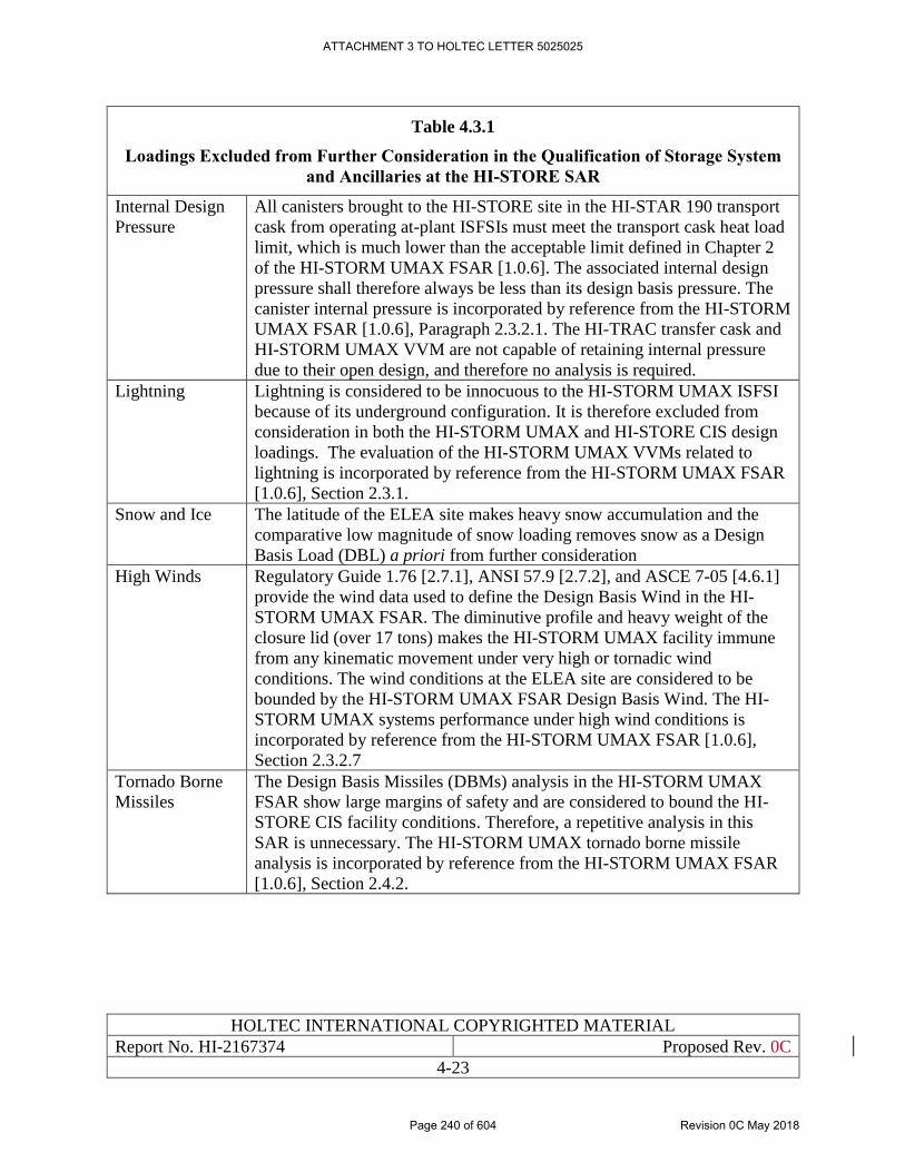
HOLTEC INTERNATIONAL COPYRIGHTED MATERIAL
Report No. HI-2167374 Proposed Rev. 0C
4-23
Table 4.3.1
Loadings Excluded from Further Consideration in the Qualification of Storage System
and Ancillaries at the HI-STORE SAR
Internal Design
Pressure
All canisters brought to the HI-STORE site in the HI-STAR 190 transport
cask from operating at-plant ISFSIs must meet the transport cask heat load
limit, which is much lower than the acceptable limit defined in Chapter 2
of the HI-STORM UMAX FSAR [1.0.6]. The associated internal design
pressure shall therefore always be less than its design basis pressure. The
canister internal pressure is incorporated by reference from the HI-STORM
UMAX FSAR [1.0.6], Paragraph 2.3.2.1. The HI-TRAC transfer cask and
HI-STORM UMAX VVM are not capable of retaining internal pressure
due to their open design, and therefore no analysis is required.
Lightning Lightning is considered to be innocuous to the HI-STORM UMAX ISFSI
because of its underground configuration. It is therefore excluded from
consideration in both the HI-STORM UMAX and HI-STORE CIS design
loadings. The evaluation of the HI-STORM UMAX VVMs related to
lightning is incorporated by reference from the HI-STORM UMAX FSAR
[1.0.6], Section 2.3.1.
Snow and Ice The latitude of the ELEA site makes heavy snow accumulation and the
comparative low magnitude of snow loading removes snow as a Design
Basis Load (DBL) a priori from further consideration
High Winds Regulatory Guide 1.76 [2.7.1], ANSI 57.9 [2.7.2], and ASCE 7-05 [4.6.1]
provide the wind data used to define the Design Basis Wind in the HI-
STORM UMAX FSAR. The diminutive profile and heavy weight of the
closure lid (over 17 tons) makes the HI-STORM UMAX facility immune
from any kinematic movement under very high or tornadic wind
conditions. The wind conditions at the ELEA site are considered to be
bounded by the HI-STORM UMAX FSAR Design Basis Wind. The HI-
STORM UMAX systems performance under high wind conditions is
incorporated by reference from the HI-STORM UMAX FSAR [1.0.6],
Section 2.3.2.7
Tornado Borne
Missiles
The Design Basis Missiles (DBMs) analysis in the HI-STORM UMAX
FSAR show large margins of safety and are considered to bound the HI-
STORE CIS facility conditions. Therefore, a repetitive analysis in this
SAR is unnecessary. The HI-STORM UMAX tornado borne missile
analysis is incorporated by reference from the HI-STORM UMAX FSAR
[1.0.6], Section 2.4.2.
ATTACHMENT 3 TO HOLTEC LETTER 5025025
Page 240 of 604 Revision 0C May 2018
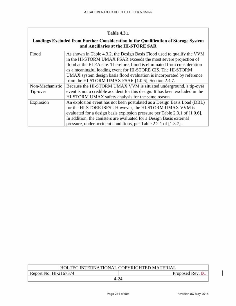
HOLTEC INTERNATIONAL COPYRIGHTED MATERIAL
Report No. HI-2167374 Proposed Rev. 0C
4-24
Table 4.3.1
Loadings Excluded from Further Consideration in the Qualification of Storage System
and Ancillaries at the HI-STORE SAR
Flood As shown in Table 4.3.2, the Design Basis Flood used to qualify the VVM
in the HI-STORM UMAX FSAR exceeds the most severe projection of
flood at the ELEA site. Therefore, flood is eliminated from consideration
as a meaningful loading event for HI-STORE CIS. The HI-STORM
UMAX system design basis flood evaluation is incorporated by reference
from the HI-STORM UMAX FSAR [1.0.6], Section 2.4.7.
Non-Mechanistic
Tip-over
Because the HI-STORM UMAX VVM is situated underground, a tip-over
event is not a credible accident for this design. It has been excluded in the
HI-STORM UMAX safety analysis for the same reason.
Explosion An explosion event has not been postulated as a Design Basis Load (DBL)
for the HI-STORE ISFSI. However, the HI-STORM UMAX VVM is
evaluated for a design basis explosion pressure per Table 2.3.1 of [1.0.6].
In addition, the canisters are evaluated for a Design Basis external
pressure, under accident conditions, per Table 2.2.1 of [1.3.7].
ATTACHMENT 3 TO HOLTEC LETTER 5025025
Page 241 of 604 Revision 0C May 2018
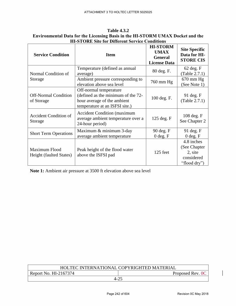
HOLTEC INTERNATIONAL COPYRIGHTED MATERIAL
Report No. HI-2167374 Proposed Rev. 0C
4-25
Table 4.3.2
Environmental Data for the Licensing Basis in the HI-STORM UMAX Docket and the
HI-STORE Site for Different Service Conditions
Service Condition Item
HI-STORM
UMAX
General
License Data
Site Specific
Data for HI-
STORE CIS
Normal Condition of
Storage
Temperature (defined as annual
average) 80 deg. F.
62 deg. F
(Table 2.7.1)
Ambient pressure corresponding to
elevation above sea level 760 mm Hg
670 mm Hg
(See Note 1)
Off-Normal Condition
of Storage
Off-normal temperature
(defined as the minimum of the 72-
hour average of the ambient
temperature at an ISFSI site.)
100 deg. F. 91 deg. F
(Table 2.7.1)
Accident Condition of
Storage
Accident Condition (maximum
average ambient temperature over a
24-hour period)
125 deg. F 108 deg. F
See Chapter 2
Short Term Operations Maximum & minimum 3-day
average ambient temperature
90 deg. F
0 deg. F
91 deg. F
0 deg. F
Maximum Flood
Height (faulted States)
Peak height of the flood water
above the ISFSI pad 125 feet
4.8 inches
(See Chapter
2, site
considered
“flood dry”)
Note 1: Ambient air pressure at 3500 ft elevation above sea level
ATTACHMENT 3 TO HOLTEC LETTER 5025025
Page 242 of 604 Revision 0C May 2018
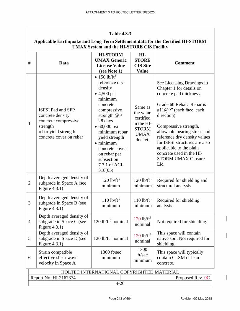
HOLTEC INTERNATIONAL COPYRIGHTED MATERIAL
Report No. HI-2167374 Proposed Rev. 0C
4-26
Table 4.3.3
Applicable Earthquake and Long Term Settlement data for the Certified HI-STORM
UMAX System and the HI-STORE CIS Facility
# Data
HI-STORM
UMAX Generic
License Value
(see Note 1)
HI-
STORE
CIS Site
Value
Comment
1
ISFSI Pad and SFP
concrete density
concrete compressive
strength
rebar yield strength
concrete cover on rebar
• 150 lb/ft3
reference dry
density
• 4,500 psi
minimum
concrete
compressive
strength @ ≤
28 days
• 60,000 psi
minimum rebar
yield strength
• minimum
concrete cover
on rebar per
subsection
7.7.1 of ACI-
318(05)
Same as
the value
certified
in the HI-
STORM
UMAX
docket.
See Licensing Drawings in
Chapter 1 for details on
concrete pad thickness.
Grade 60 Rebar. Rebar is
#11@9” (each face, each
direction)
Compressive strength,
allowable bearing stress and
reference dry density values
for ISFSI structures are also
applicable to the plain
concrete used in the HI-
STORM UMAX Closure
Lid
2
Depth averaged density of
subgrade in Space A (see
Figure 4.3.1)
120 lb/ft3
minimum
120 lb/ft3
minimum
Required for shielding and
structural analysis
3
Depth averaged density of
subgrade in Space B (see
Figure 4.3.1)
110 lb/ft3
minimum
110 lb/ft3
minimum
Required for shielding
analysis.
4
Depth averaged density of
subgrade in Space C (see
Figure 4.3.1)
120 lb/ft3 nominal 120 lb/ft3
nominal Not required for shielding.
5
Depth averaged density of
subgrade in Space D (see
Figure 4.3.1)
120 lb/ft3 nominal 120 lb/ft3
nominal
This space will contain
native soil. Not required for
shielding.
6
Strain compatible
effective shear wave
velocity in Space A
1300 ft/sec
minimum
1300
ft/sec
minimum
This space will typically
contain CLSM or lean
concrete.
ATTACHMENT 3 TO HOLTEC LETTER 5025025
Page 243 of 604 Revision 0C May 2018
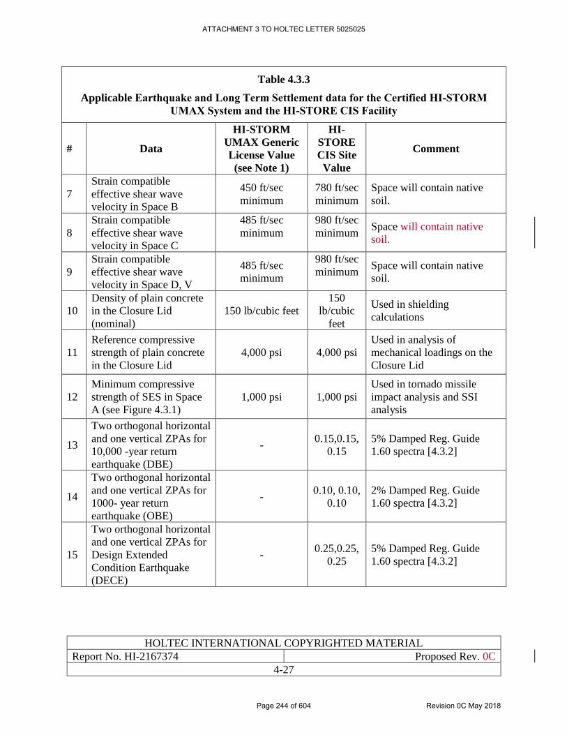
HOLTEC INTERNATIONAL COPYRIGHTED MATERIAL
Report No. HI-2167374 Proposed Rev. 0C
4-27
Table 4.3.3
Applicable Earthquake and Long Term Settlement data for the Certified HI-STORM
UMAX System and the HI-STORE CIS Facility
# Data
HI-STORM
UMAX Generic
License Value
(see Note 1)
HI-
STORE
CIS Site
Value
Comment
7
Strain compatible
effective shear wave
velocity in Space B
450 ft/sec
minimum
780 ft/sec
minimum
Space will contain native
soil.
8
Strain compatible
effective shear wave
velocity in Space C
485 ft/sec
minimum
980 ft/sec
minimum
Space will contain native
soil.
9
Strain compatible
effective shear wave
velocity in Space D, V
485 ft/sec
minimum
980 ft/sec
minimum
Space will contain native
soil.
10
Density of plain concrete
in the Closure Lid
(nominal)
150 lb/cubic feet
150
lb/cubic
feet
Used in shielding
calculations
11
Reference compressive
strength of plain concrete
in the Closure Lid
4,000 psi 4,000 psi
Used in analysis of
mechanical loadings on the
Closure Lid
12
Minimum compressive
strength of SES in Space
A (see Figure 4.3.1)
1,000 psi 1,000 psi
Used in tornado missile
impact analysis and SSI
analysis
13
Two orthogonal horizontal
and one vertical ZPAs for
10,000 -year return
earthquake (DBE)
- 0.15,0.15,
0.15
5% Damped Reg. Guide
1.60 spectra [4.3.2]
14
Two orthogonal horizontal
and one vertical ZPAs for
1000- year return
earthquake (OBE)
- 0.10, 0.10,
0.10
2% Damped Reg. Guide
1.60 spectra [4.3.2]
15
Two orthogonal horizontal
and one vertical ZPAs for
Design Extended
Condition Earthquake
(DECE)
- 0.25,0.25,
0.25
5% Damped Reg. Guide
1.60 spectra [4.3.2]
ATTACHMENT 3 TO HOLTEC LETTER 5025025
Page 244 of 604 Revision 0C May 2018
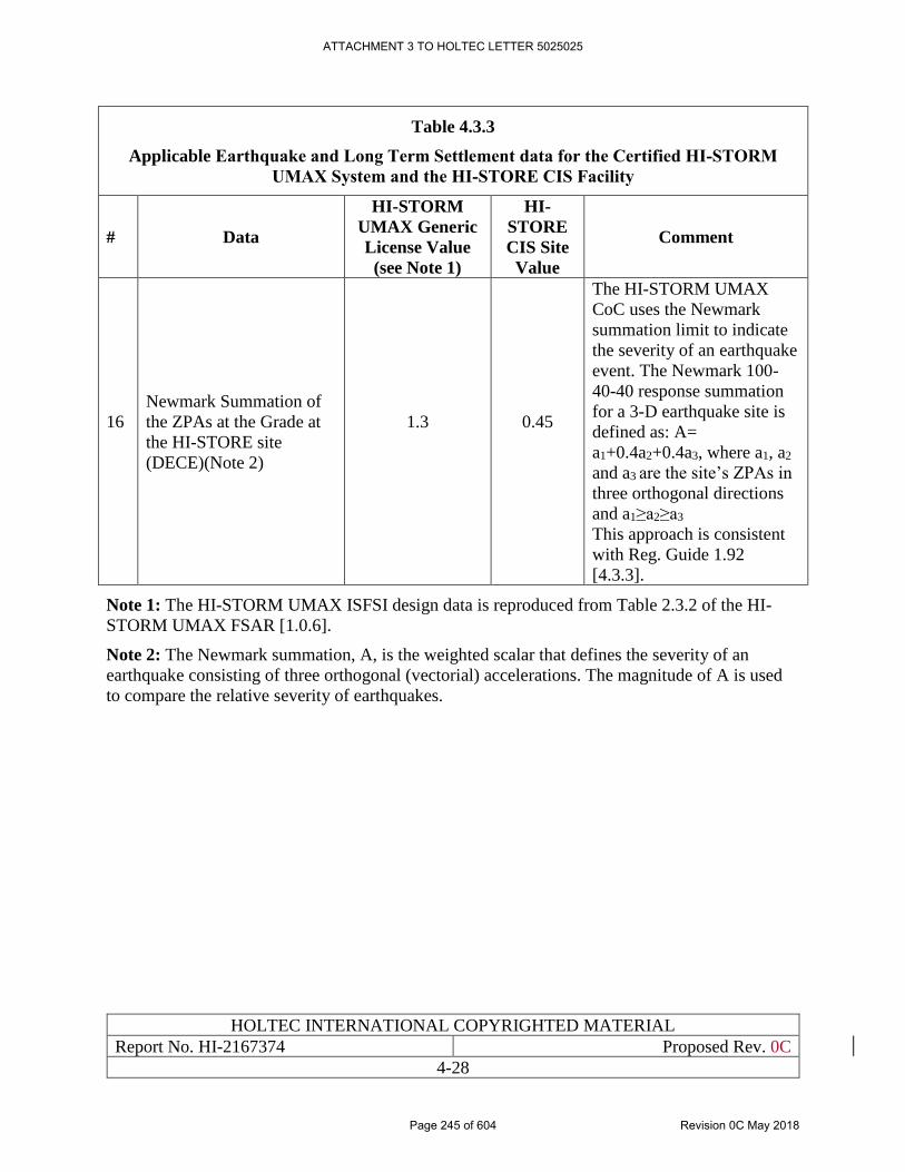
HOLTEC INTERNATIONAL COPYRIGHTED MATERIAL
Report No. HI-2167374 Proposed Rev. 0C
4-28
Table 4.3.3
Applicable Earthquake and Long Term Settlement data for the Certified HI-STORM
UMAX System and the HI-STORE CIS Facility
# Data
HI-STORM
UMAX Generic
License Value
(see Note 1)
HI-
STORE
CIS Site
Value
Comment
16
Newmark Summation of
the ZPAs at the Grade at
the HI-STORE site
(DECE)(Note 2)
1.3
0.45
The HI-STORM UMAX
CoC uses the Newmark
summation limit to indicate
the severity of an earthquake
event. The Newmark 100-
40-40 response summation
for a 3-D earthquake site is
defined as: A=
a1+0.4a2+0.4a3, where a1, a2
and a3 are the site’s ZPAs in
three orthogonal directions
and a1≥a2≥a3
This approach is consistent
with Reg. Guide 1.92
[4.3.3].
Note 1: The HI-STORM UMAX ISFSI design data is reproduced from Table 2.3.2 of the HI-
STORM UMAX FSAR [1.0.6].
Note 2: The Newmark summation, A, is the weighted scalar that defines the severity of an
earthquake consisting of three orthogonal (vectorial) accelerations. The magnitude of A is used
to compare the relative severity of earthquakes.
ATTACHMENT 3 TO HOLTEC LETTER 5025025
Page 245 of 604 Revision 0C May 2018
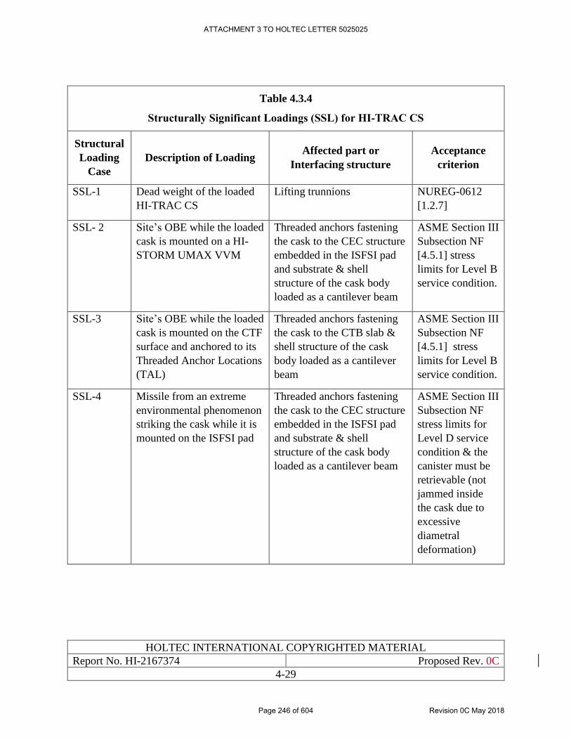
HOLTEC INTERNATIONAL COPYRIGHTED MATERIAL
Report No. HI-2167374 Proposed Rev. 0C
4-29
Table 4.3.4
Structurally Significant Loadings (SSL) for HI-TRAC CS
Structural
Loading
Case
Description of Loading Affected part or
Interfacing structure
Acceptance
criterion
SSL-1 Dead weight of the loaded
HI-TRAC CS
Lifting trunnions NUREG-0612
[1.2.7]
SSL- 2 Site’s OBE while the loaded
cask is mounted on a HI-
STORM UMAX VVM
Threaded anchors fastening
the cask to the CEC structure
embedded in the ISFSI pad
and substrate & shell
structure of the cask body
loaded as a cantilever beam
ASME Section III
Subsection NF
[4.5.1] stress
limits for Level B
service condition.
SSL-3 Site’s OBE while the loaded
cask is mounted on the CTF
surface and anchored to its
Threaded Anchor Locations
(TAL)
Threaded anchors fastening
the cask to the CTB slab &
shell structure of the cask
body loaded as a cantilever
beam
ASME Section III
Subsection NF
[4.5.1] stress
limits for Level B
service condition.
SSL-4 Missile from an extreme
environmental phenomenon
striking the cask while it is
mounted on the ISFSI pad
Threaded anchors fastening
the cask to the CEC structure
embedded in the ISFSI pad
and substrate & shell
structure of the cask body
loaded as a cantilever beam
ASME Section III
Subsection NF
stress limits for
Level D service
condition & the
canister must be
retrievable (not
jammed inside
the cask due to
excessive
diametral
deformation)
ATTACHMENT 3 TO HOLTEC LETTER 5025025
Page 246 of 604 Revision 0C May 2018
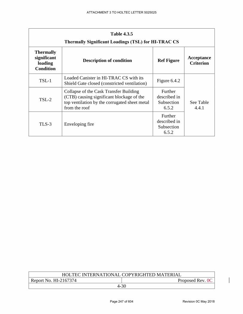
HOLTEC INTERNATIONAL COPYRIGHTED MATERIAL
Report No. HI-2167374 Proposed Rev. 0C
4-30
Table 4.3.5
Thermally Significant Loadings (TSL) for HI-TRAC CS
Thermally
significant
loading
Condition
Description of condition Ref Figure Acceptance
Criterion
TSL-1 Loaded Canister in HI-TRAC CS with its
Shield Gate closed (constricted ventilation) Figure 6.4.2
See Table
4.4.1
TSL-2
Collapse of the Cask Transfer Building
(CTB) causing significant blockage of the
top ventilation by the corrugated sheet metal
from the roof
Further
described in
Subsection
6.5.2
TLS-3 Enveloping fire
Further
described in
Subsection
6.5.2
ATTACHMENT 3 TO HOLTEC LETTER 5025025
Page 247 of 604 Revision 0C May 2018
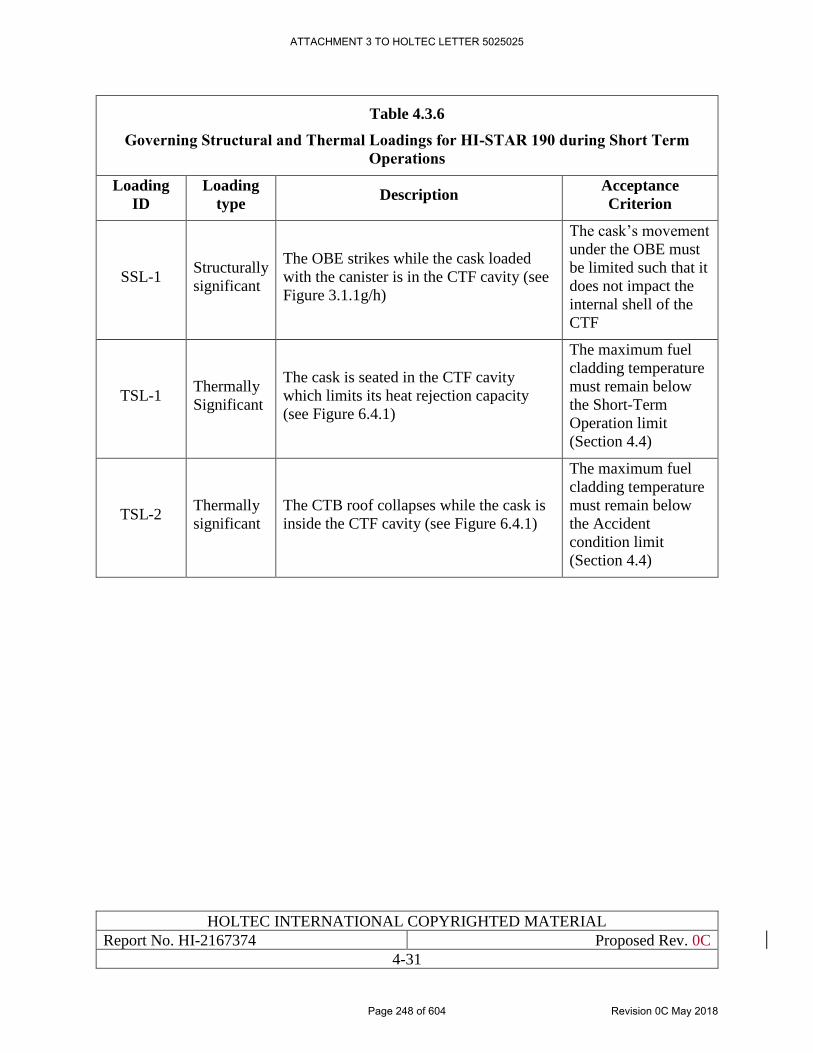
HOLTEC INTERNATIONAL COPYRIGHTED MATERIAL
Report No. HI-2167374 Proposed Rev. 0C
4-31
Table 4.3.6
Governing Structural and Thermal Loadings for HI-STAR 190 during Short Term
Operations
Loading
ID
Loading
type Description
Acceptance
Criterion
SSL-1 Structurally
significant
The OBE strikes while the cask loaded
with the canister is in the CTF cavity (see
Figure 3.1.1g/h)
The cask’s movement
under the OBE must
be limited such that it
does not impact the
internal shell of the
CTF
TSL-1 Thermally
Significant
The cask is seated in the CTF cavity
which limits its heat rejection capacity
(see Figure 6.4.1)
The maximum fuel
cladding temperature
must remain below
the Short-Term
Operation limit
(Section 4.4)
TSL-2 Thermally
significant
The CTB roof collapses while the cask is
inside the CTF cavity (see Figure 6.4.1)
The maximum fuel
cladding temperature
must remain below
the Accident
condition limit
(Section 4.4)
ATTACHMENT 3 TO HOLTEC LETTER 5025025
Page 248 of 604 Revision 0C May 2018
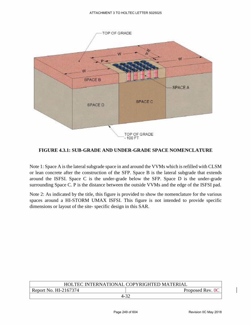
HOLTEC INTERNATIONAL COPYRIGHTED MATERIAL
Report No. HI-2167374 Proposed Rev. 0C
4-32
FIGURE 4.3.1: SUB-GRADE AND UNDER-GRADE SPACE NOMENCLATURE
Note 1: Space A is the lateral subgrade space in and around the VVMs which is refilled with CLSM
or lean concrete after the construction of the SFP. Space B is the lateral subgrade that extends
around the ISFSI. Space C is the under-grade below the SFP. Space D is the under-grade
surrounding Space C. P is the distance between the outside VVMs and the edge of the ISFSI pad.
Note 2: As indicated by the title, this figure is provided to show the nomenclature for the various
spaces around a HI-STORM UMAX ISFSI. This figure is not intended to provide specific
dimensions or layout of the site- specific design in this SAR.
ATTACHMENT 3 TO HOLTEC LETTER 5025025
Page 249 of 604 Revision 0C May 2018
HOLTEC INTERNATIONAL COPYRIGHTED MATERIAL
Report No. HI-2167374 Proposed Rev. 0C
4-33
4.4. ACCEPTANCE CRITERIA FOR CASK COMPONENTS
4.4.1 Stress and Deformation Limits
In the ASME Code, plant and system operating conditions are commonly referred to as normal,
upset, emergency, and faulted. Consistent with the terminology in NRC documents, this SAR
utilizes the terms normal, off-normal, and accident conditions.
The ASME Code defines four service conditions in addition to the Design Limits for nuclear
components. They are referred to as Level A, Level B, Level C, and Level D service limits,
respectively. Their definitions are provided in Paragraph NCA-2142.4 of the ASME Code. The
four levels are used in this SAR as follows:
i. Level A Service Limits are used to establish allowables for normal condition load
combinations.
ii. Level B Service Limits are used to establish allowables for off-normal conditions.
iii. Level C Service Limits are not used.
iv. Level D Service Limits are used to establish allowables for certain accident conditions.
The ASME Code service limits are used in the structural analyses for definition of allowable
stresses and allowable stress intensities, as applicable. Allowable stresses and stress intensities of
materials required for structural analyses are tabulated in Section 4.5. These service limits are
matched with normal, off-normal, and accident condition loads combinations in the following
subsections.
The following definitions of terms apply to the tables on stress intensity limits; these definitions
are the same as those used throughout the ASME Code:
Sm: Value of Design Stress Intensity listed in ASME Code Section II, Part D, Tables 2A, 2B
and 4
Sy: Minimum yield strength at temperature
Su: Minimum ultimate strength at temperature
The following stress limits are applicable to the SSCs at the HI-STORE CIS facility:
i. Canisters: The MPC confinement boundary is required to meet Section III, Class 1,
Subsection NB stress intensity limits. Because the MPCs (canisters) are certified to loads
in their native docket [1.0.6] that bound those at the HI-STORE site, it is not necessary to
re-perform their stress qualifications. Accordingly, the stress intensity limits for the MPC
are not presented in this SAR.
ii. HI-STORM UMAX CEC and Closure Lid: The applicable Code for stress analysis is
ASME Section III, Subsection NF. Because the HI-STORM UMAX structure has been
qualified to loads that uniformly bound those at the HI-STORE site, it is not necessary to
re-qualify the HI-STORM UMAX structure to the site specific loads in this SAR.
ATTACHMENT 3 TO HOLTEC LETTER 5025025
Page 250 of 604 Revision 0C May 2018
HOLTEC INTERNATIONAL COPYRIGHTED MATERIAL
Report No. HI-2167374 Proposed Rev. 0C
4-34
iii. Load bearing ancillaries: All structurally significant ancillaries are qualified to ASME
Section III Subsection NF. The stress limits for the different service conditions are listed
in Table 4.4.2. Appendix 4.A provides a summary of specific stress categories extracted
from the Code for NF structures
iv. Lifting and handling equipment: The applicable codes and requirements are provided in
Section 4.5.
v. Special handling devices: ANSI N14.6 [1.2.4] applied. Detailed requirements are provided
in Section 4.5.
4.4.2 Thermal Limits
The thermal acceptance criteria for all components are identical to the design criteria described in
Section 4.3.
4.4.3 Dose Limits
The off-site dose for normal operating conditions to any real individual beyond the controlled area
boundary is limited by 10CFR72.104(a) for normal conditions and 10CFR72.106 for accident
conditions (including contributions from all Short-Term operations) at the HI-STORE CIS facility.
Table 4.4.3 provides the numerical dose limits.
ATTACHMENT 3 TO HOLTEC LETTER 5025025
Page 251 of 604 Revision 0C May 2018
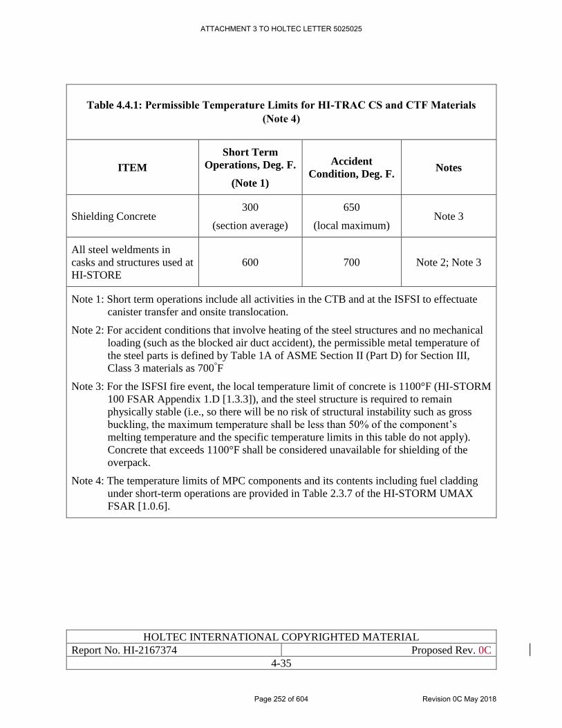
HOLTEC INTERNATIONAL COPYRIGHTED MATERIAL
Report No. HI-2167374 Proposed Rev. 0C
4-35
Table 4.4.1: Permissible Temperature Limits for HI-TRAC CS and CTF Materials
(Note 4)
ITEM
Short Term
Operations, Deg. F.
(Note 1)
Accident
Condition, Deg. F. Notes
Shielding Concrete 300
(section average)
650
(local maximum) Note 3
All steel weldments in
casks and structures used at
HI-STORE
600 700 Note 2; Note 3
Note 1: Short term operations include all activities in the CTB and at the ISFSI to effectuate
canister transfer and onsite translocation.
Note 2: For accident conditions that involve heating of the steel structures and no mechanical
loading (such as the blocked air duct accident), the permissible metal temperature of
the steel parts is defined by Table 1A of ASME Section II (Part D) for Section III,
Class 3 materials as 700°F
Note 3: For the ISFSI fire event, the local temperature limit of concrete is 1100°F (HI-STORM
100 FSAR Appendix 1.D [1.3.3]), and the steel structure is required to remain
physically stable (i.e., so there will be no risk of structural instability such as gross
buckling, the maximum temperature shall be less than 50% of the component’s
melting temperature and the specific temperature limits in this table do not apply).
Concrete that exceeds 1100°F shall be considered unavailable for shielding of the
overpack.
Note 4: The temperature limits of MPC components and its contents including fuel cladding
under short-term operations are provided in Table 2.3.7 of the HI-STORM UMAX
FSAR [1.0.6].
ATTACHMENT 3 TO HOLTEC LETTER 5025025
Page 252 of 604 Revision 0C May 2018
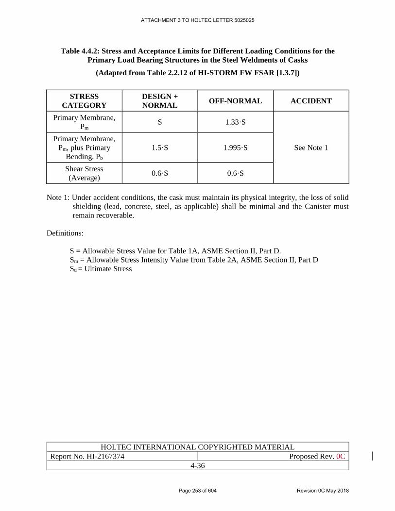
HOLTEC INTERNATIONAL COPYRIGHTED MATERIAL
Report No. HI-2167374 Proposed Rev. 0C
4-36
Table 4.4.2: Stress and Acceptance Limits for Different Loading Conditions for the
Primary Load Bearing Structures in the Steel Weldments of Casks
(Adapted from Table 2.2.12 of HI-STORM FW FSAR [1.3.7])
STRESS
CATEGORY
DESIGN +
NORMAL OFF-NORMAL ACCIDENT
Primary Membrane,
Pm S 1.33·S
See Note 1
Primary Membrane,
Pm, plus Primary
Bending, Pb
1.5·S 1.995·S
Shear Stress
(Average) 0.6·S 0.6·S
Note 1: Under accident conditions, the cask must maintain its physical integrity, the loss of solid
shielding (lead, concrete, steel, as applicable) shall be minimal and the Canister must
remain recoverable.
Definitions:
S = Allowable Stress Value for Table 1A, ASME Section II, Part D.
Sm = Allowable Stress Intensity Value from Table 2A, ASME Section II, Part D
Su = Ultimate Stress
ATTACHMENT 3 TO HOLTEC LETTER 5025025
Page 253 of 604 Revision 0C May 2018
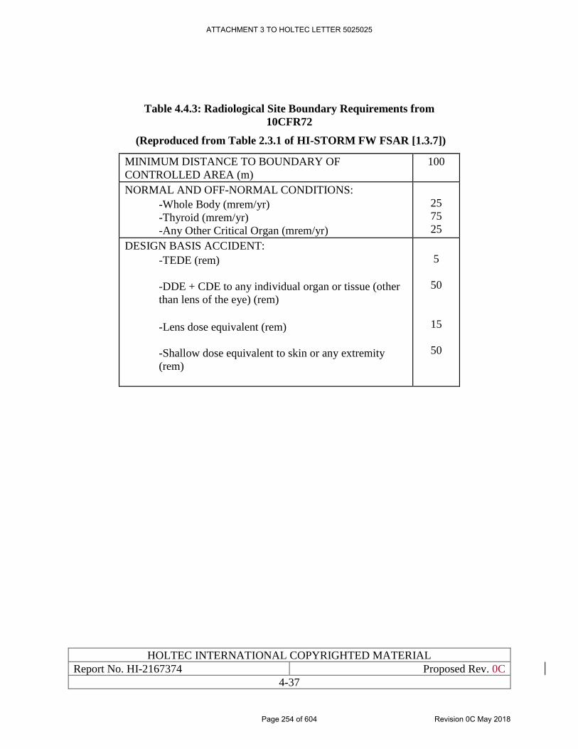
HOLTEC INTERNATIONAL COPYRIGHTED MATERIAL
Report No. HI-2167374 Proposed Rev. 0C
4-37
Table 4.4.3: Radiological Site Boundary Requirements from
10CFR72
(Reproduced from Table 2.3.1 of HI-STORM FW FSAR [1.3.7])
MINIMUM DISTANCE TO BOUNDARY OF
CONTROLLED AREA (m)
100
NORMAL AND OFF-NORMAL CONDITIONS:
-Whole Body (mrem/yr)
-Thyroid (mrem/yr)
-Any Other Critical Organ (mrem/yr)
25
75
25
DESIGN BASIS ACCIDENT:
-TEDE (rem)
-DDE + CDE to any individual organ or tissue (other
than lens of the eye) (rem)
-Lens dose equivalent (rem)
-Shallow dose equivalent to skin or any extremity
(rem)
5
50
15
50
ATTACHMENT 3 TO HOLTEC LETTER 5025025
Page 254 of 604 Revision 0C May 2018
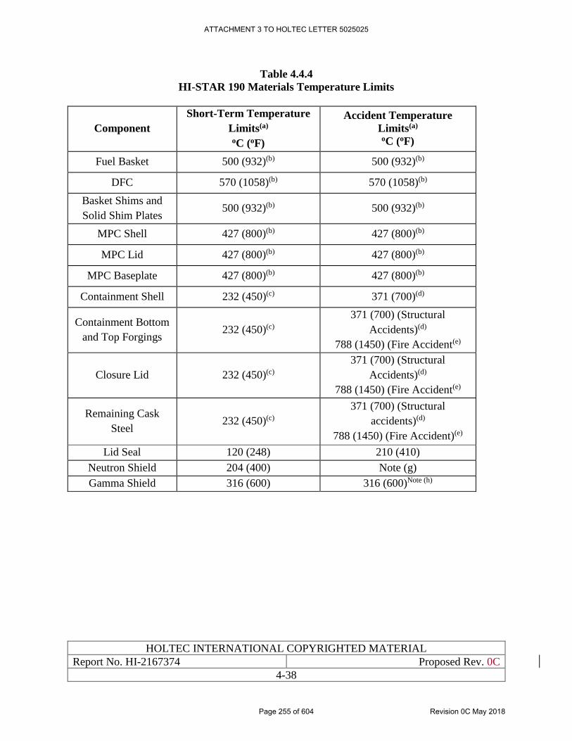
HOLTEC INTERNATIONAL COPYRIGHTED MATERIAL
Report No. HI-2167374 Proposed Rev. 0C
4-38
Table 4.4.4
HI-STAR 190 Materials Temperature Limits
Component
Short-Term Temperature
Limits(a) oC (oF)
Accident Temperature
Limits(a) oC (oF)
Fuel Basket 500 (932)(b) 500 (932)(b)
DFC 570 (1058)(b) 570 (1058)(b)
Basket Shims and
Solid Shim Plates 500 (932)(b) 500 (932)(b)
MPC Shell 427 (800)(b) 427 (800)(b)
MPC Lid 427 (800)(b) 427 (800)(b)
MPC Baseplate 427 (800)(b) 427 (800)(b)
Containment Shell 232 (450)(c) 371 (700)(d)
Containment Bottom
and Top Forgings 232 (450)(c)
371 (700) (Structural
Accidents)(d)
788 (1450) (Fire Accident(e)
Closure Lid 232 (450)(c)
371 (700) (Structural
Accidents)(d)
788 (1450) (Fire Accident(e)
Remaining Cask
Steel 232 (450)(c)
371 (700) (Structural
accidents)(d)
788 (1450) (Fire Accident)(e)
Lid Seal 120 (248) 210 (410)
Neutron Shield 204 (400) Note (g)
Gamma Shield 316 (600) 316 (600)Note (h)
ATTACHMENT 3 TO HOLTEC LETTER 5025025
Page 255 of 604 Revision 0C May 2018
HOLTEC INTERNATIONAL COPYRIGHTED MATERIAL
Report No. HI-2167374 Proposed Rev. 0C
4-39
4.5 LIFTING EQUIPMENT (CTB CRANE & VCT), SPECIAL LIFTING
DEVICES AND MISCELLANEOUS ANCILLARIES
Ancillaries for the HI-STORE CIS are equipment, systems or devices that are needed to carry out
Short Term Operations to place the canister into interim storage or to remove the loaded canister
from storage. Ancillaries are differentiated from “certified” SSCs by the fact that they are not a
part of the storage system and their detailed design is not subject to regulatory certification.
However, as required by NUREG-1567 [1.0.3], their design criteria must be articulated in this
SAR. In what follows, the design criteria for the different types of ancillaries envisaged for the HI-
STORE facility are set down in sufficient detail to ensure that the resulting detailed design will
fulfill their safety imperatives in full measure.
The description of principal ancillaries needed at the HI-STORE facility provided in Chapter 1
indicates that the list is quite small due to the fact that the canisters arrive in ready-to-store
condition at the site and the needed operations pertain entirely to handling of the loaded canister.
As a result, the ancillaries belong entirely to the class of special and standard lifting devices and
certain miscellaneous equipment.
Heavy load handling device criteria summarized in the following are adopted from the HI-STORM
FW FSAR [1.3.7]
4.5.1 Design Requirements Applicable to Lifting Devices and Special Lifting Devices
The lifting and handling ancillaries needed for operation of the HI-STORE CIS are classified as
either “lifting devices” or “special lifting devices.”
The term special lifting device refers to components to which ANSI N14.6 [1.2.4] applies. As
stated in ANSI N14.6 (both 1978 and 1993 versions), “This standard shall apply to special lifting
devices that transmit the load from lifting attachments, which are structural parts of a container to
the hook(s) of an overhead hoisting system.” Examples of special lifting devices are canister lift
cleats, cask lift brackets, and cask lift yokes.
The term lifting device as used in this SAR refers to components of a lifting and handling system
that are not classified as special lifting devices. ANSI N14.6 is not applicable to these lifting
devices. These include non-active structural components (components that bear the primary load
but are not a constituent of a moving part, e.g., gear train, hydraulic cylinder) of the system.
4.5.1.1 Stress Compliance Criteria Applicable to Lifting Devices (LDs):
Examples of lifting devices used with Holtec’s systems include the VCT or the main girder of the
gantry crane used in the transport cask receiving area of the Cask Transfer Building (CTB).
The stress compliance criteria for lifting devices are taken from the code applicable to the specific
component. For example, slings are required to meet the guidelines of ANSI B30.9 [4.5.6], and
overhead beams in a crane are required to meet the guidelines of an applicable consensus national
standard selected by the designer, such as AISC, CMAA, or ASME Code (Subsection NF [4.5.1]).
The transporter used to handle the loaded transfer cask or overpack during transport operations
must be engineered to provide a high integrity handling of the load, defined as a lifting/handling
ATTACHMENT 3 TO HOLTEC LETTER 5025025
Page 256 of 604 Revision 0C May 2018
HOLTEC INTERNATIONAL COPYRIGHTED MATERIAL
Report No. HI-2167374 Proposed Rev. 0C
4-40
operation wherein the risk of an uncontrolled lowering of the heavy load is non-credible. In
handling equipment, such as a transporter, high integrity handling is achieved through (a) a body
and any vertical columns designed to comply with stress limits of ASME Section III, Subsection
NF, Class 3, (b) an overhead beam that is single-failure-proof, and (c) redundant drop protection
features. Single failure proof handling capability is achieved by ensuring that the applicable factor
of safety is 200% of that required by the reference design code or national consensus standard. It
is acceptable to have certain load carrying members (such as the lifting towers in a vertical cask
transporter) designed with redundant devices and others (such as the transverse beam) designed to
the doubled factor of safety in order to meet the criteria set above.
4.5.1.2 Stress Compliance Criteria Applicable to Special Lifting Devices (SLDs):
The stress compliance criteria for special lifting devices are taken directly from ANSI N14.6
[1.2.4], which requires safety factors of three against the yield strength and five times against
ultimate strength. Although not required by ANSI N14.6, Holtec International requires the yield
and ultimate strengths of the primary load bearing member used in the stress analysis to be at its
average metal temperature (in lieu of the ambient temperature).
4.5.1.3 Single Failure Proof Criteria
In order for a lifting device or special lifting device to be considered single failure proof, the design
must also follow the guidance in NUREG-0612 [1.2.7], which requires that a single failure proof
device have twice the normal safety margin. This designation can be achieved by either providing
redundant devices or providing twice the design safety factor as required by the applicable code.
Therefore, for a lifting device to be considered single failure proof, the applicable code
requirements should be doubled, or a redundant lifting device should be provided. Similarly, for a
special lifting device to be considered single failure proof, the design safety factors in ANSI N14.6
[1.2.4] should be doubled, or a redundant special lifting device should be provided.
4.5.1.4 Stress Criteria and Critical Load Drop Accident
Both NUREG-0612 [1.2.7] and ANSI N14.6 [1.2.4] allow for a load drop analysis to be performed.
If the consequences of that analysis are below the permissible dose rate and sub-criticality limits,
the increased safety factors are not required. If the handling devices are designed to the correct
stress limits, then the drop accident is non-credible.
4.5.2 Cask Transfer Building (CTB) Crane
The CTB crane is a rail-supported (gantry) load handling device located in the Cask Transfer
Building (CTB). It is the principal load handling device used to lift, upend, down-end and
translocate the casks & other heavy loads used inside the CTB. It is the in-CTB counterpart to the
Vertical Cask Transporter (VCT) which principally handles the transfer cask and other heavy loads
outside the CTB. The Cask Crane renders the following repetitive operations:
1. Removal of the transport cask from the railcar
2. Removal of the transport cask impact limiters
3. Movement of the transport cask in and out of the CTF
ATTACHMENT 3 TO HOLTEC LETTER 5025025
Page 257 of 604 Revision 0C May 2018
HOLTEC INTERNATIONAL COPYRIGHTED MATERIAL
Report No. HI-2167374 Proposed Rev. 0C
4-41
4. Movement of the transport cask (empty and loaded) inside the CTB
5. The ITS designation of the crane is provided in Table 4.2.1
4.5.2.1 Structural
The CTB Crane shall be a single failure proof load handling device designed and built in
accordance with the provisions of ASME NOG-1 [3.0.1].
The applicable Design Basis dead weight and seismic loadings on the CTB Crane are set down in
Table 4.5.1.
- The crane shall be designed for a load capacity specified in Table 4.5.2.
- For loading conditions that exceed the duration defined as seismic-exempt, a seismic
analysis of the loaded crane shall be performed in accordance with the provisions of ASME
NOG-1 [3.01].
4.5.2.2 Thermal
The CTB crane does not operate in an elevated temperature environment. The design temperature
of the gantry crane is conservatively specified in Table 4.5.1 to be well above the maximum
ambient temperature in the CTB.
4.5.2.3 Shielding
The CTB crane does not provide a shielding function.
4.5.2.4 Confinement
The CTB crane does not provide a confinement function.
4.5.2.5 Criticality Control
The CTB crane does not perform any criticality control function.
4.5.2.6 Operational Requirements
- The crane design shall allow interfacing with all the lifting ancillaries such as MPC Lift
Extension, HI-TRAC CS Lifting Device, and HI-STAR 190 Lift Yoke.
- The crane design shall provide for the ability to upend and lift the HI-STAR from the railcar.
- The crane design shall meet the requirements per Table 4.5.1 and 4.5.2.
- The crane shall meet the operational requirements per ASME NOG-1 [3.0.1].
4.5.2.7 Environmental Conditions
The ambient conditions for the crane are identical to those for the VCT summarized in Table
4.5.3. In addition, the design of the crane shall preclude materials that may degrade under the
radiation from casks during the crane’s service life.
ATTACHMENT 3 TO HOLTEC LETTER 5025025
Page 258 of 604 Revision 0C May 2018
HOLTEC INTERNATIONAL COPYRIGHTED MATERIAL
Report No. HI-2167374 Proposed Rev. 0C
4-42
4.5.2.7 Interfaces and Media Requirements
The electrical supply requirements are specified in Table 4.5.2. The crane shall have ability to
receive signals from lifted equipment in order to fulfill operational requirements described in
Chapter 10.
4.5.2.8 Electric Requirements
The following requirements shall be met.
The crane shall meet the electrical requirements per ASME NOG-1 [3.0.1]
- All safety relevant functions such as interlocking mechanisms, releases, selections,
acceptances, and other connections shall be established via hard wire. All other functions
can be realized via PLC. The operating and display elements which have no safety
implications can be linked with a bus system to the PLC. The speed and torque controllers
can be linked with the PLC directly via bus system. The electrical design shall be properly
configured for easy maintenance.
- Phase and voltage protection shall be provided for main power feed.
- Sufficient space shall be provided for the cable routing and buses into the electrical cabinet.
- Properly sized electrical grounding conductors shall be implemented in the cable routing
of the main components.
4.5.3 Vertical Cask Transporter
The Vertical Cask Transporter (VCT) is the principal load handling device used at the HI-STORE
CIS ISFSI. This Subsection provides the essential design requirements that the VCT procured for
the HI-STORE facility must fulfill to comply with this SAR.
The VCT is a U-shaped, tracked vehicle (also called a tracked crawler) used for handling and on-
site transport of loaded and empty HI-TRAC transfer cask. The structural characteristics of the so-
called “wheeled” VCT are identical and therefore are not spelled out separately. The tracked
crawler configuration has been selected for the HI-STORE site because of greater in-use
experience with it in the United States. Use of a wheeled crawler at a later date will require a safety
evaluation pursuant to 10CFR72.48.
The VCT is used for transferring an MPC, loaded in a HI-TRAC transfer cask, at the CTF and the
HI-STORM UMAX cavity. The constituent parts of the VCT are indicated in Figure 4.5.1. As
shown in Figure 4.5.1, the VCT consists of the vehicle main frame, the lifting towers, an overhead
crossbeam that connects between the lifting towers, a cask restraint system, the drive system and
control system, and the cask lifting attachment. The transfer cask is supported by the lifting
attachments that are connected to the overhead beam (Figure 4.5.2). The overhead beam is
supported at the ends by a pair of lifting towers. The lifting towers transfer the cask weight directly
to the vehicle frame. The lifting towers have an independent means of affording protection against
uncontrolled lowering of the load. Figure 4.5.3 illustrates the dual-path MPC handling system
utilized for Canister raising or lowering operations. In summary, used in conjunction with the
special lifting devices, it provides the critical lifting and handling functions associated with the
ATTACHMENT 3 TO HOLTEC LETTER 5025025
Page 259 of 604 Revision 0C May 2018
HOLTEC INTERNATIONAL COPYRIGHTED MATERIAL
Report No. HI-2167374 Proposed Rev. 0C
4-43
canister transfer operations. The VCT is also used to transfer HI-TRAC CS from CTB to the HI-
STORM UMAX ISFSI.
The ITS designation of the VCT and its constituent components is provided in Table 4.2.1.
4.5.3.1 General Design Requirements
Prevention of a cask or canister drop is afforded by design conformance with NUREG-0612 [1.2.7]
and ANSI N14.6 [1.2.4] combined with the use of automatic redundant drop protection features
along with hydraulic check valves and enhanced safety margins. The automatic drop protection
features shall prevent an uncontrolled lowering of the load under any potential single system
failure or loss of hydraulic or electric power at any time, including travel.
The VCT vehicle frame shall be designed in accordance with applicable industry standards such
as ASME Section III, Subsection NF, for Class 3, linear-type supports or equivalent such as AISC
[4.5.9]. The MPC downloader system shall be fully redundant and each side shall be capable of
holding the entire weight of a loaded MPC (Figure 4.5.3). Overhead beam deflection shall meet
the requirements of [4.5.11]
The overhead beam, lifting attachments, and MPC downloader pulley/pins and/or other
attachments shall be designed in accordance with ANSI N14.6 [1.2.4] and the applicable guidance
of NUREG-0612, Section 5.1.6 [1.2.7]. The safety factor shall be based on the lower of 1/6th the
yield strength or 1/10th the ultimate strength.
Jack/Lifting Towers (including top lugs connecting to overhead beam pins and the pins connecting
the Lifting Towers to the frame) shall be designed in accordance with ASME Section III,
Subsection NF, for Class 3, Linear-Type Supports [4.5.1] and ASME B30.1 [4.5.8] with design
safety factors consistent with the guidance of [1.2.7], Section 5.1.6 (1)(a) for the specific load
lifted.
The Load Drop Protection System shall be designed to meet the applicable stress limits of ASME
Section III, Subsection NF, for Class 3, Linear-Type Supports using 115% of the design basis load.
The hydraulic fluids used in jacks or other hydraulic equipment shall be appropriate for use
throughout the range of service temperatures listed in Table 4.5.1. The hydraulic fluids used in the
cask transporter should have a flashpoint greater than or equal to 500°F per ASTM D92 [4.5.10].
Hydraulic fluids with flashpoints lower than 500°F may be used provided they are included as
combustible material in the applicable fire analyses.
The Lifting Cylinders shall meet the requirements of ASME B30.1-2009 [4.5.8].High-energy
hydraulic lines shall be guarded or properly secured for personnel protection to ensure no
personnel injuries from whipping of a ruptured line.
4.5.3.2 Fabrication
The VCT shall be designed, fabricated, inspected, and tested in accordance with the applicable
guidance of NUREG-0612 [1.2.7]. All directly loaded tension and compression members shall be
engineered to satisfy the enhanced safety criteria of paragraphs 5.1.6 (1) (a) and (b) of [1.2.7]. All
ATTACHMENT 3 TO HOLTEC LETTER 5025025
Page 260 of 604 Revision 0C May 2018
HOLTEC INTERNATIONAL COPYRIGHTED MATERIAL
Report No. HI-2167374 Proposed Rev. 0C
4-44
welding shall comply with [4.5.3] or [4.5.4]. The VCT shall be manufactured in accordance with
the provisions of [4.5.5]. Slings shall comply with the provisions of [4.5.6].
4.5.3.3 Structural
The following structural requirements apply to the components comprising the HI-STORE CIS
facility VCT:
i. All materials used in the design of the overhead beam and lifting towers shall be ASTM
approved or equal and shall be consistent with the ITS category of the part.
ii. Prevention of a cask or canister drop is afforded by design conformance with NUREG-
0612 [1.2.7] and ANSI N14.6 [1.2.4] combined with enhanced safety margins and the use
of redundant drop protection features, such as hydraulic check valves and a fail-safe
electrical control system;
iii. The VCT vehicle frame shall be designed in accordance with applicable industry standards
such as ASME Section III, Subsection NF, for Class 3, linear-type supports or equivalent,
or AISC [4.5.9];
iv. The overhead beam, lifting attachments, and MPC downloader pulley/pins and/or other
attachments shall be designed in accordance with ANSI N14.6 [1.2.4] and the applicable
guidance of NUREG-0612 [1.2.7], Section 5.1.6. The safety factor shall be based on the
lower of 1/6th the yield strength or 1/10th the ultimate strength;
v. Jacks shall be designed in accordance with ASME Section III, Subsection NF, for Class 3,
Linear-Type Supports [4.5.1] and ASME B30.1 [4.5.8] with design safety factors
consistent with the guidance of NUREG-0612 [1.2.7], Section 5.1.6 (1)(a) for the specific
load lifted. Multi-stage jacks may have several rated capacities based on the extension
stage. The jacks’ rated capacity shall be coupled with the load based on the jack
configuration for the lift of the load.
vi. The applicable Design Basis dead weight and seismic loadings on the VCT are listed in
Table 4.5.3. The VCT shall be shown to not tip-over under any specified service condition.
The vehicle's lateral and transverse center of gravity shall be lower than the HI-TRAC’s
lateral and transverse center of gravity while transporting a loaded HI-STORM. Tip-over
shall assume a 7% transverse grade in all modes. A national consensus standard such as
ASCE 43-05 [5.4.5] shall be used for stability evaluation. The seismic restraints and their
attachment points on the VCT frame shall be designed to meet the Level D stress limits of
ASME Subsection NF.
4.5.3.4 Functional Requirements
The VCT shall be operated and controlled by means of a control panel. The control panel shall be
suitably positioned to allow for easy access and operator visibility during cask engagement, lifting,
movement, and lowering. The control panels shall be enclosed or suitably protected from weather
conditions. From the operator’s chair, the operator shall be able to see all gauges and indicators
necessary to accurately monitor the condition of both the power source and the hydraulic system
at all times. The VCT shall be equipped with a dead man’s throttle.
ATTACHMENT 3 TO HOLTEC LETTER 5025025
Page 261 of 604 Revision 0C May 2018
HOLTEC INTERNATIONAL COPYRIGHTED MATERIAL
Report No. HI-2167374 Proposed Rev. 0C
4-45
The VCT shall be equipped with an emergency stop switch tethered to the rear of the vehicle by
means of a retractable cord reel. The emergency stop switch shall be easily and sagely carried and
operated by ground personnel walking behind or to either side of the VCT.
The VCT shall be equipped with flashing movement warning lights and audible alarm with a
minimum 30’ range.
The VCT shall be capable of being towed and secured against movement in the event that it
becomes inoperable during transit.
The design shall ensure that any electrical malfunction in the control system, motors, or power
supplies will not lead to an uncontrolled lowering of the load.
Portable fire extinguisher(s) meeting the requirements of NFPA 10 [4.5.7, 4.5.12].
A catch pan or a double wall fuel tank with a hose connection to route spills away from the VCT
shall be mounted beneath the fuel tank.
The VCT shall be equipped with auxiliary power receptacles. Voltage, frequency, amperage
ratings, and receptacle shall be specified by Holtec to meet site specific requirements.
4.5.3.5 Thermal
The VCT does not operate in an elevated temperature environment. The design temperature of the
VCT is conservatively specified in Table 4.5.3 to be well above the maximum ambient temperature
in the CTB, on the VCT haul path, and the ISFSI pad.
4.5.3.6 Shielding
The VCT does not provide a shielding function.
4.5.3.7 Confinement
The VCT does not provide a confinement function.
4.5.3.8 Criticality Control
The VCT does not perform any criticality control function.
4.5.3.9 Material Failure Modes
All materials used in the design of the overhead beam and lifting towers shall be ASTM approved
or equal and shall be consistent with the ITS category of the part.
The material properties and allowable stress values for all structural steel members shall be taken
from the applicable national consensus standard. Acceptance criteria for the Charpy testing
requirements for the overhead beam, lifting towers, cask transporter lift points and MPC
downloader system load bearing components shall be per ASME Section III, Subsection NF [4.5.1]
or ANSI N14.6 [1.2.4]. The lowest service temperature used for developing the test parameters for
Charpy testing shall be equal to 0°F for all the components mentioned above. Lateral expansion
will be per Table NF-2331(a)-3 and required Cv energies shall be extrapolated from Fig. NF-
2331(a)-2 for Class 3 Materials.
ATTACHMENT 3 TO HOLTEC LETTER 5025025
Page 262 of 604 Revision 0C May 2018
HOLTEC INTERNATIONAL COPYRIGHTED MATERIAL
Report No. HI-2167374 Proposed Rev. 0C
4-46
Fatigue failure modes of primary structural members whose failure may result in the uncontrolled
lowering of the load shall be evaluated. A minimum safety factor of 2 on the number of permissible
loading cycles (1000 loading cycles) for critical members shall apply.
4.5.3.10 Environmental Conditions
The ambient conditions for the VCT are summarized in Table 4.5.3. The design of the VCT shall
preclude materials that may degrade under the radiation from casks during the service life.
4.5.4 Miscellaneous Ancillaries
Miscellaneous ancillaries are those weldments that are not used in a load lifting function and do
not contain or in contact with fissile material. Such ancillaries do not render a confinement or
criticality function. Certain ancillaries, however, are used to reduce crew dose such as tungsten
screens and lead blankets. Such non-structural ancillaries are also called “accessories” because
their design is guided by ALARA, not by any regulatory regimen.
The miscellaneous ancillaries are subject to mechanical loadings under any operating modes shall
meet the following design criteria:
i. The Design loads and associated applicable to the ancillary under normal and accident
conditions (if any) shall be defined based on its function and application.
ii. ASME Section III Subsection NF Class 3 is designated as the governing code for purposes
of stress analysis of the ancillary. Specifically, Subsection NF shall be used to demonstrate:
a. Compliance with the Code stress limits
b. Absence of the risk of brittle fracture at low service conditions (See Table 2.7.1)
c. Absence of elastic instability effects such as buckling
d. Absence of the risk of fatigue failure
iii. The load rating and maximum/minimum operating temperature for the ancillary shall be
marked on the ancillary.
The stress and strength tables for common materials used in the manufacturing of ancillaries have
been extracted from [1.3.3] and are provided in this sub-section.
ATTACHMENT 3 TO HOLTEC LETTER 5025025
Page 263 of 604 Revision 0C May 2018
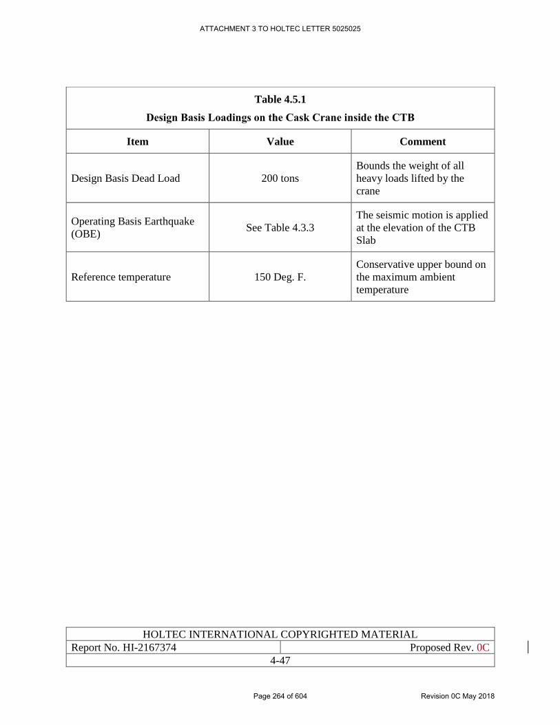
HOLTEC INTERNATIONAL COPYRIGHTED MATERIAL
Report No. HI-2167374 Proposed Rev. 0C
4-47
Table 4.5.1
Design Basis Loadings on the Cask Crane inside the CTB
Item Value Comment
Design Basis Dead Load 200 tons
Bounds the weight of all
heavy loads lifted by the
crane
Operating Basis Earthquake
(OBE) See Table 4.3.3
The seismic motion is applied
at the elevation of the CTB
Slab
Reference temperature 150 Deg. F.
Conservative upper bound on
the maximum ambient
temperature
ATTACHMENT 3 TO HOLTEC LETTER 5025025
Page 264 of 604 Revision 0C May 2018
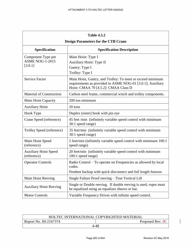
HOLTEC INTERNATIONAL COPYRIGHTED MATERIAL
Report No. HI-2167374 Proposed Rev. 0C
4-48
Table 4.5.2
Design Parameters for the CTB Crane
Specification Specification Description
Component Type per
ASME NOG-1-2015
[3.0.1]
Main Hoist: Type I
Auxiliary Hoist: Type II
Gantry: Type I
Trolley: Type I
Service Factor Main Hoist, Gantry, and Trolley: To meet or exceed minimum
requirements as provided in ASME NOG-01 [3.0.1]; Auxiliary
Hoist: CMAA 70 [4.5.2]: CMAA Class D
Material of Construction Carbon steel frame, commercial winch and trolley components.
Main Hoist Capacity 200 ton minimum
Auxiliary Hoist 20 tons
Hook Type Duplex (sister) hook with pin eye
Crane Speed (reference) 45 feet /min (infinitely variable speed control with minimum
30:1 speed range)
Trolley Speed (reference) 35 feet/min (infinitely variable speed control with minimum
30:1 speed range)
Main Hoist Speed
(reference)
5 feet/min (infinitely variable speed control with minimum 100:1
speed range)
Auxiliary Hoist Speed
(reference)
20 feet/min (infinitely variable speed control with minimum
100:1 speed range)
Operator Controls Radio Control – To operate on Frequencies as allowed by local
codes.
Pendent backup with quick disconnect and full length festoon.
Main Hoist Reeving Single Failure Proof reeving – True Vertical Lift
Auxiliary Hoist Reeving Single or Double reeving. If double reeving is used, ropes must
be equalized using an equalizer sheave or bar.
Motor Controls Variable Frequency Drives with infinite speed control.
ATTACHMENT 3 TO HOLTEC LETTER 5025025
Page 265 of 604 Revision 0C May 2018
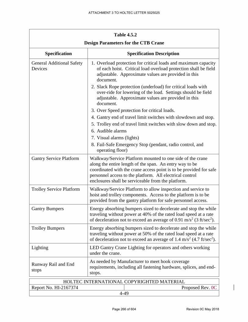
HOLTEC INTERNATIONAL COPYRIGHTED MATERIAL
Report No. HI-2167374 Proposed Rev. 0C
4-49
Table 4.5.2
Design Parameters for the CTB Crane
Specification Specification Description
General Additional Safety
Devices
1. Overload protection for critical loads and maximum capacity
of each hoist. Critical load overload protection shall be field
adjustable. Approximate values are provided in this
document.
2. Slack Rope protection (underload) for critical loads with
over-ride for lowering of the load. Settings should be field
adjustable. Approximate values are provided in this
document.
3. Over Speed protection for critical loads.
4. Gantry end of travel limit switches with slowdown and stop.
5. Trolley end of travel limit switches with slow down and stop.
6. Audible alarms
7. Visual alarms (lights)
8. Fail-Safe Emergency Stop (pendant, radio control, and
operating floor)
Gantry Service Platform Walkway/Service Platform mounted to one side of the crane
along the entire length of the span. An entry way to be
coordinated with the crane access point is to be provided for safe
personnel access to the platform. All electrical control
enclosures shall be serviceable from the platform.
Trolley Service Platform Walkway/Service Platform to allow inspection and service to
hoist and trolley components. Access to the platform is to be
provided from the gantry platform for safe personnel access.
Gantry Bumpers Energy absorbing bumpers sized to decelerate and stop the while
traveling without power at 40% of the rated load speed at a rate
of deceleration not to exceed an average of 0.91 m/s2 (3 ft/sec2).
Trolley Bumpers Energy absorbing bumpers sized to decelerate and stop the while
traveling without power at 50% of the rated load speed at a rate
of deceleration not to exceed an average of 1.4 m/s2 (4.7 ft/sec2).
Lighting LED Gantry Crane Lighting for operators and others working
under the crane.
Runway Rail and End
stops
As needed by Manufacturer to meet hook coverage
requirements, including all fastening hardware, splices, and end-
stops.
ATTACHMENT 3 TO HOLTEC LETTER 5025025
Page 266 of 604 Revision 0C May 2018
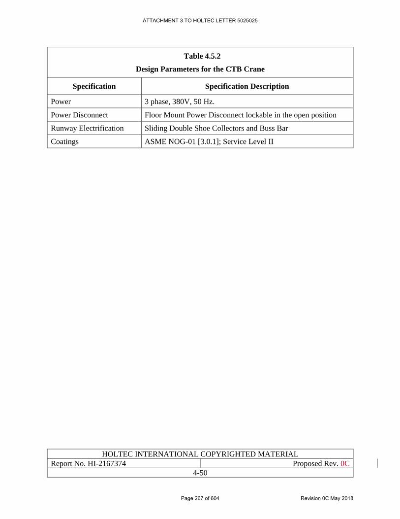
HOLTEC INTERNATIONAL COPYRIGHTED MATERIAL
Report No. HI-2167374 Proposed Rev. 0C
4-50
Table 4.5.2
Design Parameters for the CTB Crane
Specification Specification Description
Power 3 phase, 380V, 50 Hz.
Power Disconnect Floor Mount Power Disconnect lockable in the open position
Runway Electrification Sliding Double Shoe Collectors and Buss Bar
Coatings ASME NOG-01 [3.0.1]; Service Level II
ATTACHMENT 3 TO HOLTEC LETTER 5025025
Page 267 of 604 Revision 0C May 2018
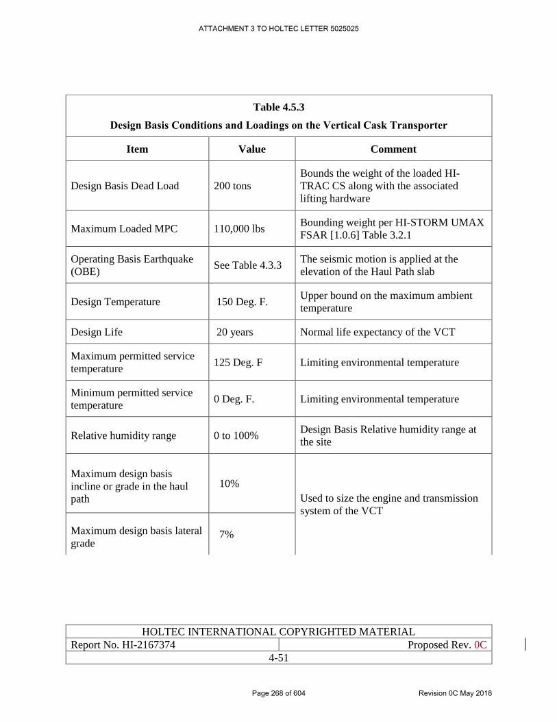
HOLTEC INTERNATIONAL COPYRIGHTED MATERIAL
Report No. HI-2167374 Proposed Rev. 0C
4-51
Table 4.5.3
Design Basis Conditions and Loadings on the Vertical Cask Transporter
Item Value Comment
Design Basis Dead Load 200 tons
Bounds the weight of the loaded HI-
TRAC CS along with the associated
lifting hardware
Maximum Loaded MPC 110,000 lbs Bounding weight per HI-STORM UMAX
FSAR [1.0.6] Table 3.2.1
Operating Basis Earthquake
(OBE) See Table 4.3.3
The seismic motion is applied at the
elevation of the Haul Path slab
Design Temperature 150 Deg. F. Upper bound on the maximum ambient
temperature
Design Life 20 years Normal life expectancy of the VCT
Maximum permitted service
temperature 125 Deg. F Limiting environmental temperature
Minimum permitted service
temperature 0 Deg. F. Limiting environmental temperature
Relative humidity range 0 to 100% Design Basis Relative humidity range at
the site
Maximum design basis
incline or grade in the haul
path
10%
Used to size the engine and transmission
system of the VCT
Maximum design basis lateral
grade 7%
ATTACHMENT 3 TO HOLTEC LETTER 5025025
Page 268 of 604 Revision 0C May 2018
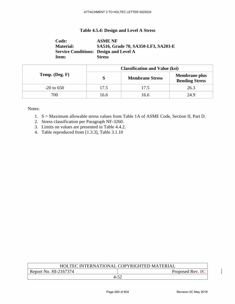
HOLTEC INTERNATIONAL COPYRIGHTED MATERIAL
Report No. HI-2167374 Proposed Rev. 0C
4-52
Table 4.5.4: Design and Level A Stress
Code: ASME NF
Material: SA516, Grade 70, SA350-LF3, SA203-E
Service Conditions: Design and Level A
Item: Stress
Temp. (Deg. F)
Classification and Value (ksi)
S Membrane Stress Membrane plus
Bending Stress
-20 to 650 17.5 17.5 26.3
700 16.6 16.6 24.9
Notes:
1. S = Maximum allowable stress values from Table 1A of ASME Code, Section II, Part D.
2. Stress classification per Paragraph NF-3260.
3. Limits on values are presented in Table 4.4.2.
4. Table reproduced from [1.3.3], Table 3.1.10
ATTACHMENT 3 TO HOLTEC LETTER 5025025
Page 269 of 604 Revision 0C May 2018
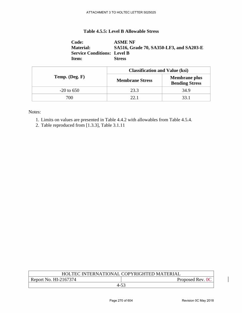
HOLTEC INTERNATIONAL COPYRIGHTED MATERIAL
Report No. HI-2167374 Proposed Rev. 0C
4-53
Table 4.5.5: Level B Allowable Stress
Code: ASME NF
Material: SA516, Grade 70, SA350-LF3, and SA203-E
Service Conditions: Level B
Item: Stress
Temp. (Deg. F)
Classification and Value (ksi)
Membrane Stress Membrane plus
Bending Stress
-20 to 650 23.3 34.9
700 22.1 33.1
Notes:
1. Limits on values are presented in Table 4.4.2 with allowables from Table 4.5.4.
2. Table reproduced from [1.3.3], Table 3.1.11
ATTACHMENT 3 TO HOLTEC LETTER 5025025
Page 270 of 604 Revision 0C May 2018
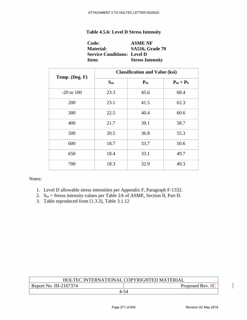
HOLTEC INTERNATIONAL COPYRIGHTED MATERIAL
Report No. HI-2167374 Proposed Rev. 0C
4-54
Table 4.5.6: Level D Stress Intensity
Code: ASME NF
Material: SA516, Grade 70
Service Conditions: Level D
Item: Stress Intensity
Temp. (Deg. F) Classification and Value (ksi)
Sm Pm Pm + Pb
-20 to 100 23.3 45.6 68.4
200 23.1 41.5 62.3
300 22.5 40.4 60.6
400 21.7 39.1 58.7
500 20.5 36.8 55.3
600 18.7 33.7 50.6
650 18.4 33.1 49.7
700 18.3 32.9 49.3
Notes:
1. Level D allowable stress intensities per Appendix F, Paragraph F-1332.
2. Sm = Stress intensity values per Table 2A of ASME, Section II, Part D.
3. Table reproduced from [1.3.3], Table 3.1.12
ATTACHMENT 3 TO HOLTEC LETTER 5025025
Page 271 of 604 Revision 0C May 2018
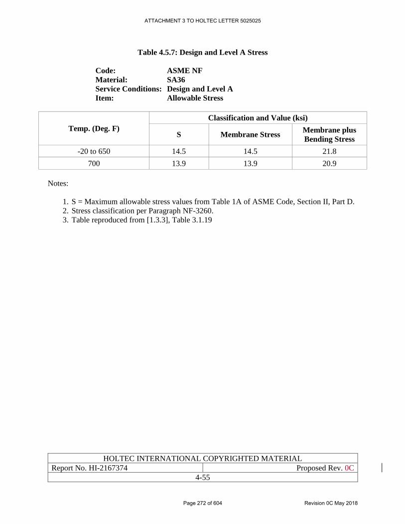
HOLTEC INTERNATIONAL COPYRIGHTED MATERIAL
Report No. HI-2167374 Proposed Rev. 0C
4-55
Table 4.5.7: Design and Level A Stress
Code: ASME NF
Material: SA36
Service Conditions: Design and Level A
Item: Allowable Stress
Temp. (Deg. F)
Classification and Value (ksi)
S Membrane Stress Membrane plus
Bending Stress
-20 to 650 14.5 14.5 21.8
700 13.9 13.9 20.9
Notes:
1. S = Maximum allowable stress values from Table 1A of ASME Code, Section II, Part D.
2. Stress classification per Paragraph NF-3260.
3. Table reproduced from [1.3.3], Table 3.1.19
ATTACHMENT 3 TO HOLTEC LETTER 5025025
Page 272 of 604 Revision 0C May 2018
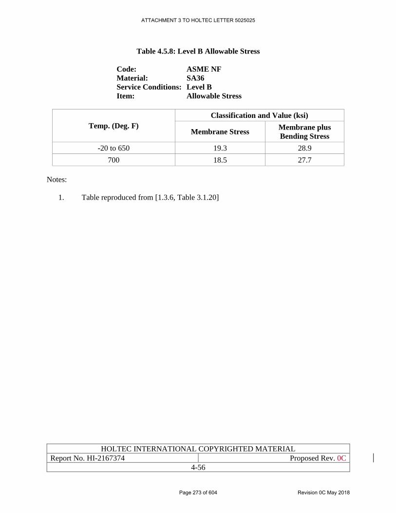
HOLTEC INTERNATIONAL COPYRIGHTED MATERIAL
Report No. HI-2167374 Proposed Rev. 0C
4-56
Table 4.5.8: Level B Allowable Stress
Code: ASME NF
Material: SA36
Service Conditions: Level B
Item: Allowable Stress
Temp. (Deg. F)
Classification and Value (ksi)
Membrane Stress Membrane plus
Bending Stress
-20 to 650 19.3 28.9
700 18.5 27.7
Notes:
1. Table reproduced from [1.3.6, Table 3.1.20]
ATTACHMENT 3 TO HOLTEC LETTER 5025025
Page 273 of 604 Revision 0C May 2018

HOLTEC INTERNATIONAL COPYRIGHTED MATERIAL
Report No. HI-2167374 Proposed Rev. 0C
4-57
Table 4.5.9: Level D Stress Intensity
Code: ASME NF
Material: SA36
Service Conditions: Level D
Item: Stress Intensity
Temp. (Deg. F) Classification and Value (ksi)
Sm Pm Pm + Pb
-20 to 100 19.3 43.2 64.8
200 19.3 37.0 55.5
300 19.3 36.0 54.0
400 19.3 34.7 52.1
500 19.3 32.8 49.2
600 17.7 30.0 45.0
650 17.4 29.5 44.3
700 17.3 29.2 43.8
Notes:
1. Level D allowable stress intensities per Appendix F, Paragraph F-1332.
2. Sm = Stress intensity values per Table 2A of ASME, Section II, Part D.
3. Table reproduced from [1.3.3], Table 3.1.21
ATTACHMENT 3 TO HOLTEC LETTER 5025025
Page 274 of 604 Revision 0C May 2018
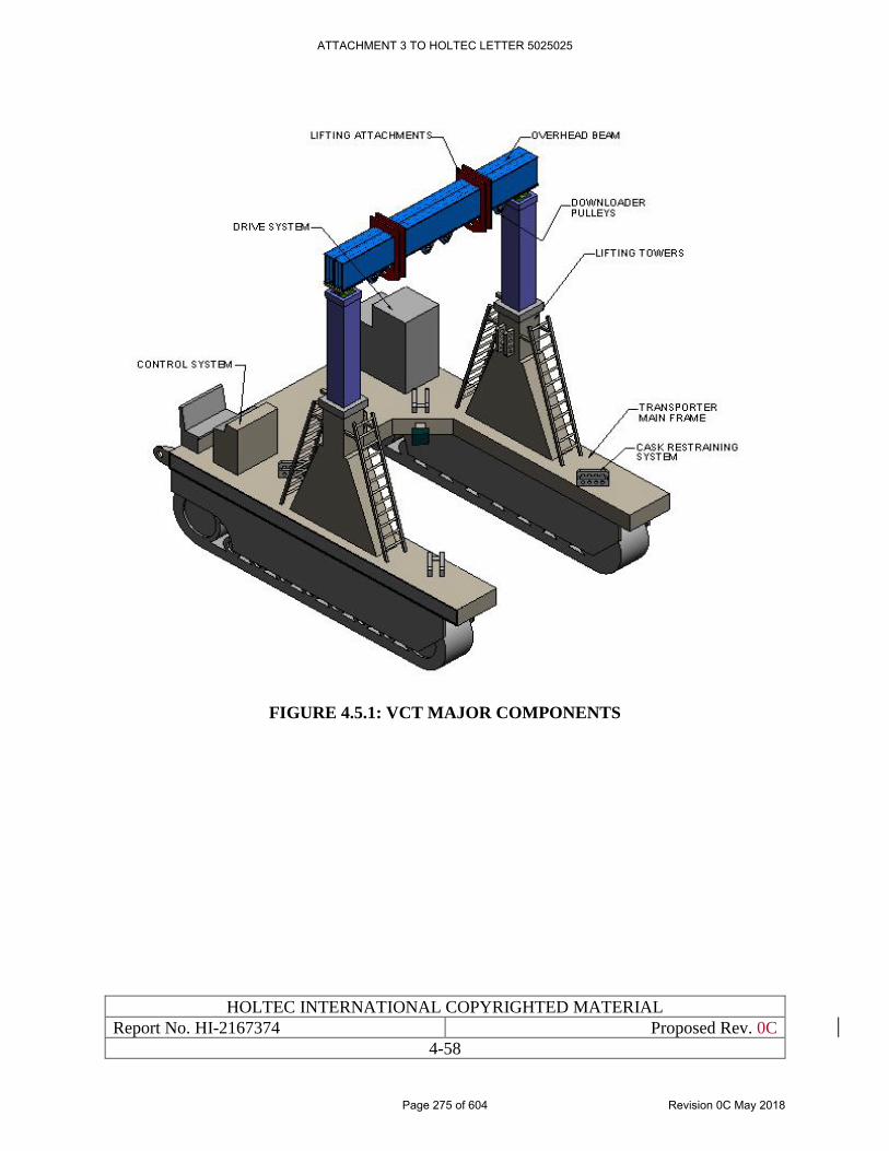
HOLTEC INTERNATIONAL COPYRIGHTED MATERIAL
Report No. HI-2167374 Proposed Rev. 0C
4-58
FIGURE 4.5.1: VCT MAJOR COMPONENTS
ATTACHMENT 3 TO HOLTEC LETTER 5025025
Page 275 of 604 Revision 0C May 2018
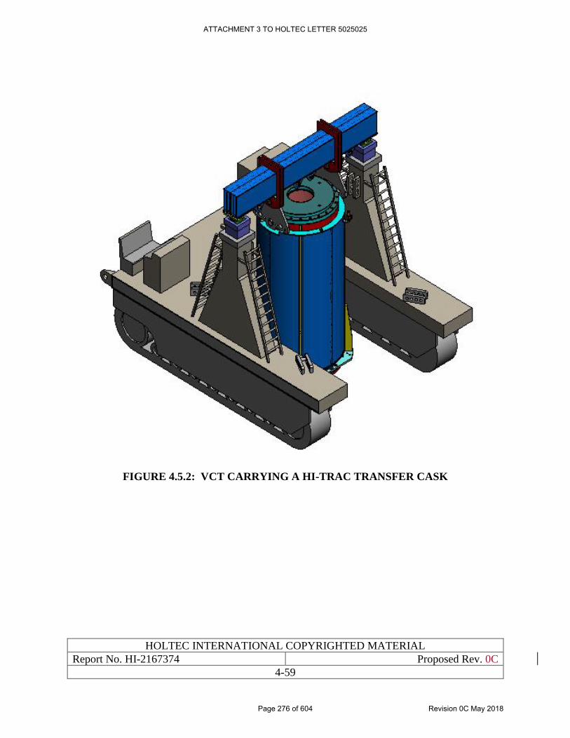
HOLTEC INTERNATIONAL COPYRIGHTED MATERIAL
Report No. HI-2167374 Proposed Rev. 0C
4-59
FIGURE 4.5.2: VCT CARRYING A HI-TRAC TRANSFER CASK
ATTACHMENT 3 TO HOLTEC LETTER 5025025
Page 276 of 604 Revision 0C May 2018
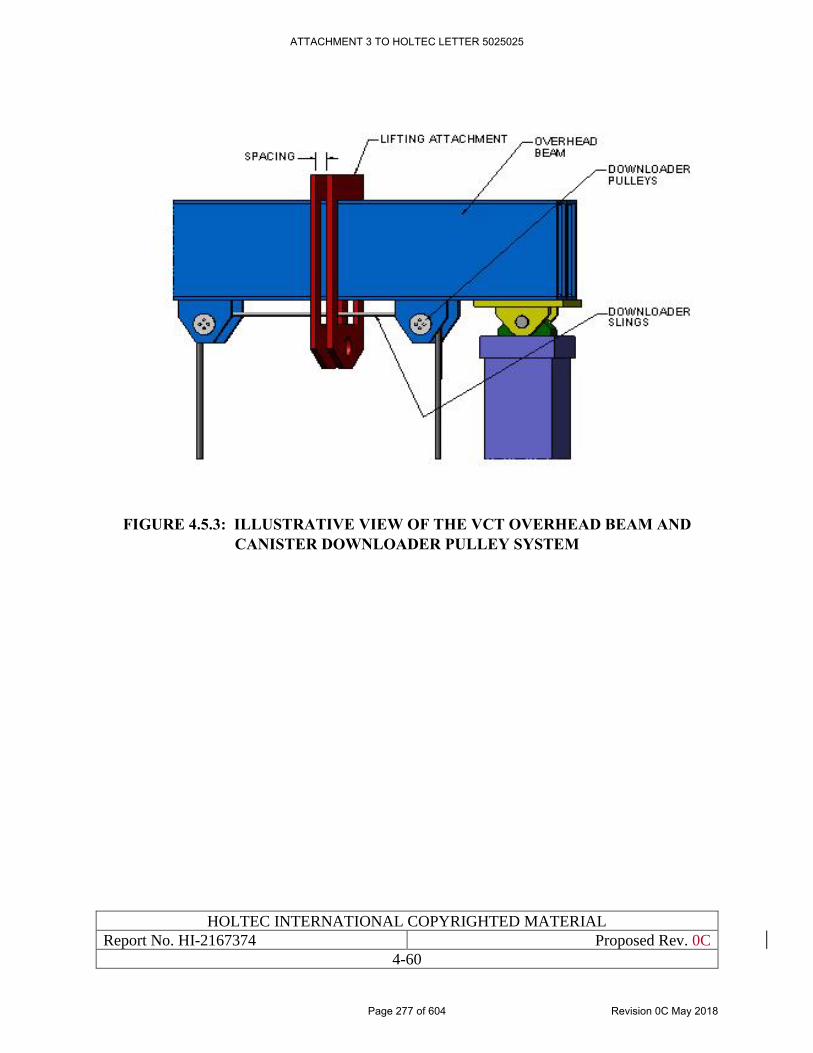
HOLTEC INTERNATIONAL COPYRIGHTED MATERIAL
Report No. HI-2167374 Proposed Rev. 0C
4-60
FIGURE 4.5.3: ILLUSTRATIVE VIEW OF THE VCT OVERHEAD BEAM AND
CANISTER DOWNLOADER PULLEY SYSTEM
ATTACHMENT 3 TO HOLTEC LETTER 5025025
Page 277 of 604 Revision 0C May 2018
HOLTEC INTERNATIONAL COPYRIGHTED MATERIAL
Report No. HI-2167374 Proposed Rev. 0C
4-61
4.6 DESIGN CRITERIA FOR THE CASK TRANSFER BUILDING (CTB)
4.6.1 Design Features of the CTB
The Cask Transfer Building (CTB) is a NITS structure at the HI-STORE CIS facility. It serves as
a weather enclosure for the cask handling equipment, facilities and structures, all of which are
floor mounted. The CTB Crane, summarized in Section 4.5, is a gantry crane mounted on a set of
rails founded on the CTB’s slab. The layout of the equipment and ancillaries in the CTB is provided
in Figure 3.1.2 of Chapter 3. Chapter 10 contains the summary of the operations that are envisaged
to occur in the CTB.
The CTB is a conventional sheet metal building consisting of a thick load bearing concrete slab
mentioned above and a set of knee-high concrete walls which support the steel frame that serves
as the backbone for the building. Corrugated sheet metal panels are fastened to the steel frame to
create the lateral enclosure system. An overhead truss provides the framework to support the roof,
also made of corrugated sheet metal.
The CTB is designed to the provisions of [4.6.1] and New Mexico’s state and local Building Codes.
The building steel (wall and roof structures) design is informed by the load combinations and
criteria in IBC-2015 [4.6.4] and ASCE 7-10 [4.6.2]. While the CTB renders no safety function, it
houses safety-significant equipment. Therefore, under an extreme environmental phenomenon,
such as high wind, it is necessary to postulate that its roof collapses and falls on the ITS SSCs
below. Table 4.6.1 provides loading data for designing the CTB walls and roof structure; this data
is used in the building collapse evaluation in Chapter 5.
4.6.2 CTB Slab
The CTB is founded on a thick reinforced concrete slab whose essential design data is summarized
in Table 4.6.2.
The CTB slab is designed to the following governing dead and live loads:
(i) The live load from the railroad car wheels carrying the loaded transport cask
(ii) The live load from the CTB Crane carrying the transport or the HI-TRAC CS cask
(iii) The live load from the loaded VCT (Figure 4.5.2)
The CTB slab is designed to meet the strength requirements of ACI 318-05 [5.3.1] for the
following governing load combinations:
Load Combination # 1: 1.4D
Load Combination # 2: 1.2D + 1.6L
Load Combination # 3: 1.2D + L + E
where D is the dead load of the CTB slab including long-term settlement effects, L is the live load
acting on the CTB slab (including weight of VCT, CTB Crane, etc.), and E is the OBE for the site.
ATTACHMENT 3 TO HOLTEC LETTER 5025025
Page 278 of 604 Revision 0C May 2018
HOLTEC INTERNATIONAL COPYRIGHTED MATERIAL
Report No. HI-2167374 Proposed Rev. 0C
4-62
Table 4.6.2 provides the essential design data for the CTB slab which is used in Chapter 5 to
demonstrate its compliance with ACI-318 using bounding values of loadings (live and seismic).
ATTACHMENT 3 TO HOLTEC LETTER 5025025
Page 279 of 604 Revision 0C May 2018
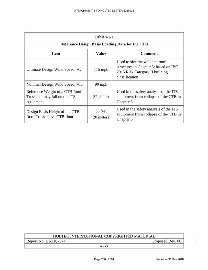
HOLTEC INTERNATIONAL COPYRIGHTED MATERIAL
Report No. HI-2167374 Proposed Rev. 0C
4-63
Table 4.6.1
Reference Design Basis Loading Data for the CTB
Item Value Comment
Ultimate Design Wind Speed, Vult 115 mph
Used to size the wall and roof
structures in Chapter 5; based on IBC
2015 Risk Category II building
classification
Nominal Design Wind Speed, Vasd 90 mph
Reference Weight of a CTB Roof
Truss that may fall on the ITS
equipment
32,400 lb
Used in the safety analysis of the ITS
equipment from collapse of the CTB in
Chapter 5
Design Basis Height of the CTB
Roof Truss above CTB floor
66 feet
(20 meters)
Used in the safety analysis of the ITS
equipment from collapse of the CTB in
Chapter 5
ATTACHMENT 3 TO HOLTEC LETTER 5025025
Page 280 of 604 Revision 0C May 2018
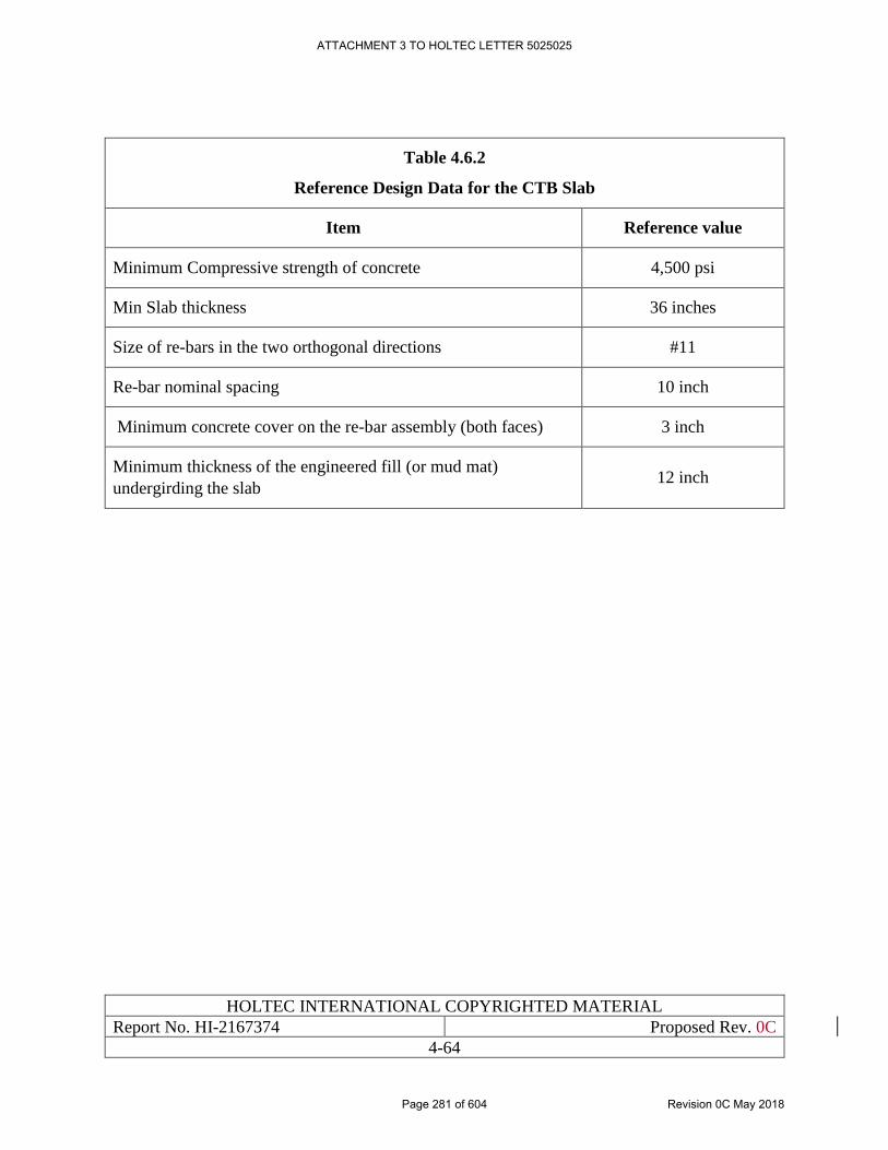
HOLTEC INTERNATIONAL COPYRIGHTED MATERIAL
Report No. HI-2167374 Proposed Rev. 0C
4-64
Table 4.6.2
Reference Design Data for the CTB Slab
Item Reference value
Minimum Compressive strength of concrete 4,500 psi
Min Slab thickness 36 inches
Size of re-bars in the two orthogonal directions #11
Re-bar nominal spacing 10 inch
Minimum concrete cover on the re-bar assembly (both faces) 3 inch
Minimum thickness of the engineered fill (or mud mat)
undergirding the slab 12 inch
ATTACHMENT 3 TO HOLTEC LETTER 5025025
Page 281 of 604 Revision 0C May 2018
HOLTEC INTERNATIONAL COPYRIGHTED MATERIAL
Report No. HI-2167374 Proposed Rev. 0C
4-65
4.7 SUMMARY OF DESIGN CRITERIA
The Design Criteria set down in this chapter seek to ensure that during any condition of storage
(normal, off-normal or accident) and during canister transfer operations, the following metrics of
safety will be observed:
i. The confinement boundary is not breached.
ii. There is no risk of exceeding the neutron multiplication factor limit of 0.95 including all
uncertainties and biases.
iii. The temperature of the used fuel remains below the limit set forth in ISG-11, Rev. 3 [4.0.1]
which insures that the fuel will not undergo any significant degradation in storage.
iv. The stresses in the primary structural members remain within the applicable ASME code
limits under every condition of storage.
v. The accreted site boundary radiation dose from the storage system meets the 72.104 &
10CFR 72.106 limits for the normal and accident conditions, respectively.
vi. The occurrence of an accidental load drop event is rendered non-credible by the use of
single failure proof lifting and handling devices.
vii. There is no risk of brittle fracture of a primary load bearing member in the storage system
under all storage scenarios.
viii. There is no risk of fatigue failure in a load bearing member under all applicable storage
scenarios.
ix. There is no risk of structural instability (buckling), large deformation or similar non-linear
behavior in any primary load bearing member during any (normal, off-normal and
accident) condition of storage.
The above criteria are fulfilled either by reference to the HI-STORM UMAX FSAR [1.0.6] or by
the safety analyses performed in support of this SAR. For the latter case, the justification for
relying on the safety analysis in [1.0.6] is provided.
In particular, the information presented in this chapter shows that every loading germane to long
term storage of Canisters in the HI-STORM UMAX VVM at a HI-STORM UMAX ISFSI, as
described in the HI-STORM UMAX FSAR [1.0.6], either equals or bounds its site-specific
counterpart for the HI-STORE CIS ISFSI. Likewise, the structural margins of safety in the short-
term operations involving the HI-STAR transfer cask have been quantified in the HI-STORM
UMAX FSAR for a much stronger seismic event than the Design Basis Earthquake (10,000 year
return earthquake) applicable to the HI-STORE site. Finally, the Design Criteria set down in
Chapter 4 of this SAR for the non- certified SSCs such as the vertical cask transporter, gantry crane
and special lifting devices are identical to those specified for such components in other HI-STORM
dockets [1.3.3, 1.3.7].
Therefore, the safety analyses for all aspects of safe deployment and storage of HI-STORM
UMAX at the HI-STORE site, including structural, criticality, thermal and confinement are
ATTACHMENT 3 TO HOLTEC LETTER 5025025
Page 282 of 604 Revision 0C May 2018
HOLTEC INTERNATIONAL COPYRIGHTED MATERIAL
Report No. HI-2167374 Proposed Rev. 0C
4-66
substantially pre-empted by the qualifications in the HI-STORM UMAX FSAR making a re-
evaluation for HI-STORE unnecessary. The only exceptions are:
i. The site boundary dose qualification which must be performed to demonstrate compliance
with the 10CFR72.104 dose limits under the maximum fuel inventory scenario, i.e., when
every storage location in the ISFSI is occupied.
ii. The temperature of the fuel within the stored canister at the HI-STORE ISFSI will meet
the normal storage condition limit of ISG-11, Rev. 3. This analysis is required because the
high altitude of the ISFSI (Table 2.7.1) reduces the air ventilation rate. The maximum heat
load, however, is limited by the rating of the transport cask which is substantially less than
the thermal capacity of HI-STORM UMAX licensed by the USNRC (Docket # 72-1040).
Therefore, the ISG temperature limit is expected to be met with a large margin.
Nevertheless, to support the safety case, this margin is quantified in Chapter 6.
In addition, a new transfer cask, named HI-TRAC CS has been introduced in this docket. While
the design of this transfer cask is similar to the other HI-TRAC models certified in other HI-
STORM dockets, viz. [1.0.6, 1.3.3, 1.3.7], there are sufficient physical differences to warrant a
safety analysis of HI-TRAC CS to be performed. The applicable design criteria for such analyses
are provided in this chapter.
Finally, all ancillaries must meet the design criteria presented in Section 4.5.
ATTACHMENT 3 TO HOLTEC LETTER 5025025
Page 283 of 604 Revision 0C May 2018
HOLTEC INTERNATIONAL COPYRIGHTED MATERIAL
Report No. HI-2167374 Proposed Rev. 0C
4A-1
APPENDIX 4.A: [PROPRIETARY APPENDIX WITHHELD IN ITS
ENTIRETY IN ACCORDANCE WITH 10CFR2.390]
ATTACHMENT 3 TO HOLTEC LETTER 5025025
Page 284 of 604 Revision 0C May 2018
HOLTEC INTERNATIONAL COPYRIGHTED MATERIAL
Report No.: HI-2167374 Proposed Rev. 0A
5-1
CHAPTER 5: INSTALLATION AND STRUCTURAL
EVALUATION
5.0 INTRODUCTION
The HI-STORE CIS facility utilizes the subterranean canister storage system referred to as HI-
STORM UMAX certified in NRC Docket #72-1040 [1.0.6]. As the safety determination in this
chapter shows, from the structural standpoint, the HI-STORM UMAX design can be adopted in
its entirety from its native docket for the HI-STORE CIS facility without the need for any
modification. The basis for this adoption, as elaborated in this chapter, is supported by the existing
structural qualifications of the HI-STORM UMAX system that have been previously reviewed by
the NRC and which uniformly bound all HI-STORE CIS site-specific loadings.
However, while the safety analyses for HI-STORM UMAX can be adopted for HI-STORE, that
is not the case for the ancillary systems, structures and components (SSCs) needed to operate the
facility. These ancillaries are listed and their operational roles are summarized in Subsection 1.2.7.
In this chapter, the structural safety qualification of each ancillary envisaged to be used at HI-
STORE CIS, showing its compliance with its Design Criteria (presented in Chapter 4), is
documented. The computed design margin for the ancillary SSCs under their respective design
basis loads along with the safety analyses in the HI-STORM UMAX FSAR for the certified storage
system underpins the safety case for the HI-STORE site.
The HI-STORM UMAX system as licensed in Docket # 72-1040 allows for a variable depth
canister storage cavity to accommodate canisters of different heights. At the HI-STORE CIS site,
all the storage cavities will be built to the same fixed depth, which is within the design limits of
the licensed HI-STORM UMAX system. The structural qualification of HI-STORM UMAX in
Docket # 72-1040 is based on the tallest and heaviest MPC-37 canisters (South Texas) because
they define the bounding inertia loads. The Licensing Drawings in Section 1.5 of this SAR contain
the depictions of the fixed depth HI-STORM UMAX cavity adapted from Docket #72-1040. For
structural purposes, the deepest cavity to store the longest and heaviest canister defines the
governing configuration. In Table 5.0.1, a comparison of the Design Basis Loads (DBLs) in its
generic FSAR [1.0.6] and their site specific loading counterparts is presented to demonstrate that
the Design Basis structural loads bound the site specific loads (SSLs) in every instance. Therefore,
fresh qualifying analyses for the storage system at the HI-STORE installation, in addition to those
in [5.4.7], are not necessary.
The bounding weights for the various dry cask storage components and ancillary equipment used
at the HI-STORE CIS facility are listed in Table 5.0.2.
Finally, to facilitate convenient access to the referenced material, a list of sections germane to this
chapter is provided in a tabular form. Table 5.0.3 provides a listing of the material adopted in this
chapter by reference from other licensed dockets.
All references are placed within square brackets in this report and are compiled in Chapter 19 of this report.
ATTACHMENT 3 TO HOLTEC LETTER 5025025
Page 285 of 604 Revision 0C May 2018
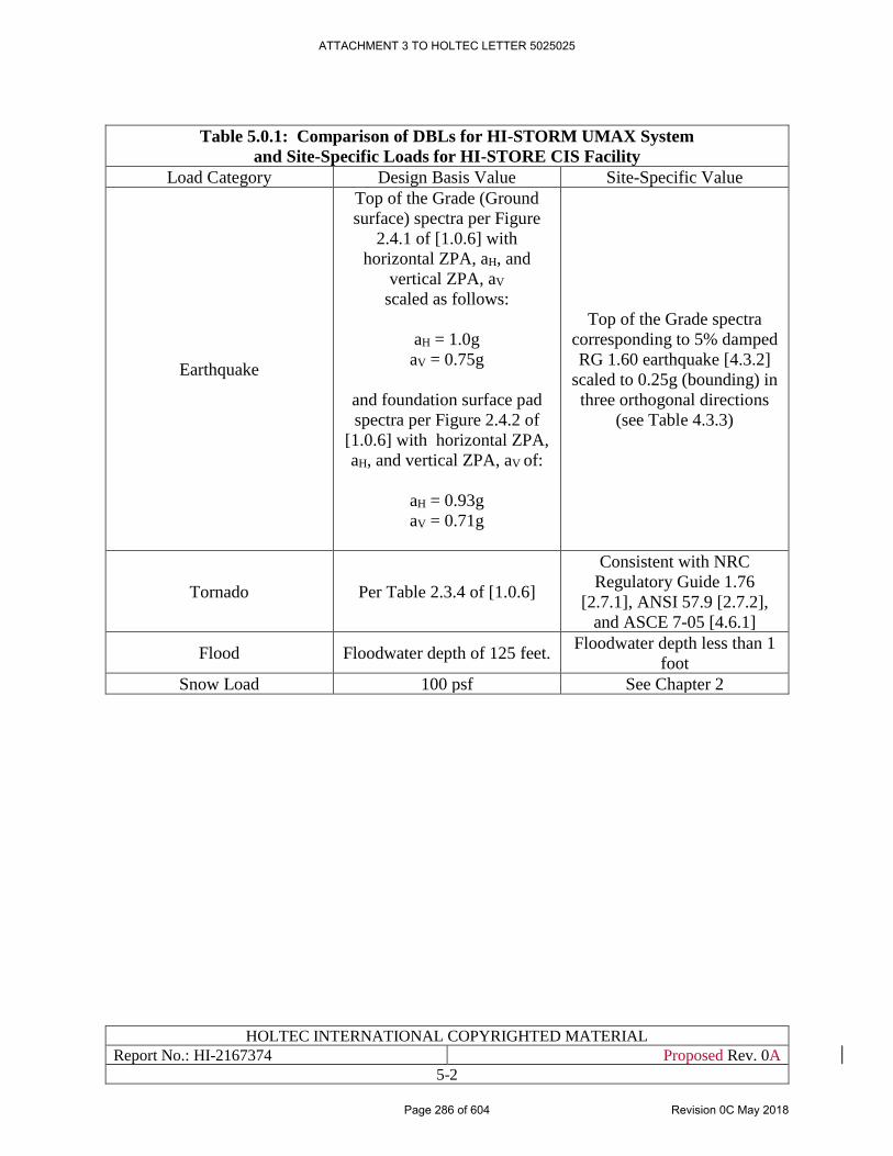
HOLTEC INTERNATIONAL COPYRIGHTED MATERIAL
Report No.: HI-2167374 Proposed Rev. 0A
5-2
Table 5.0.1: Comparison of DBLs for HI-STORM UMAX System
and Site-Specific Loads for HI-STORE CIS Facility
Load Category Design Basis Value Site-Specific Value
Earthquake
Top of the Grade (Ground
surface) spectra per Figure
2.4.1 of [1.0.6] with
horizontal ZPA, aH, and
vertical ZPA, aV
scaled as follows:
aH = 1.0g
aV = 0.75g
and foundation surface pad
spectra per Figure 2.4.2 of
[1.0.6] with horizontal ZPA,
aH, and vertical ZPA, aV of:
aH = 0.93g
aV = 0.71g
Top of the Grade spectra
corresponding to 5% damped
RG 1.60 earthquake [4.3.2]
scaled to 0.25g (bounding) in
three orthogonal directions
(see Table 4.3.3)
Tornado Per Table 2.3.4 of [1.0.6]
Consistent with NRC
Regulatory Guide 1.76
[2.7.1], ANSI 57.9 [2.7.2],
and ASCE 7-05 [4.6.1]
Flood Floodwater depth of 125 feet. Floodwater depth less than 1
foot
Snow Load 100 psf See Chapter 2
ATTACHMENT 3 TO HOLTEC LETTER 5025025
Page 286 of 604 Revision 0C May 2018
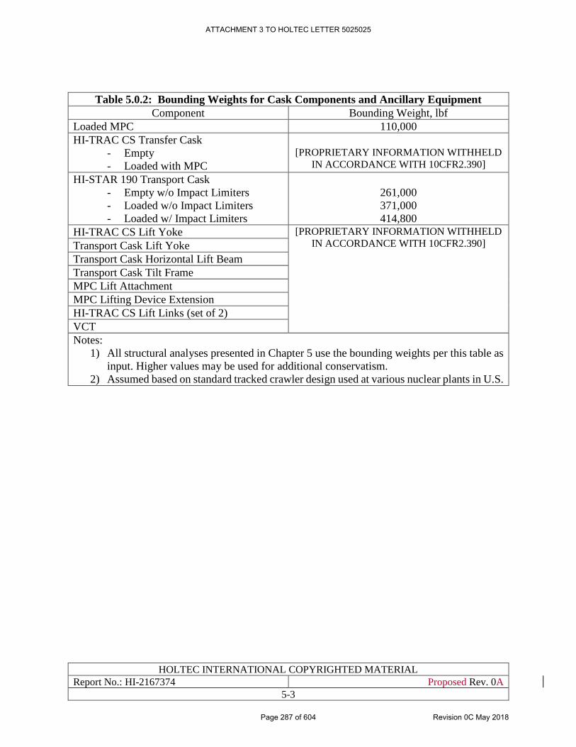
HOLTEC INTERNATIONAL COPYRIGHTED MATERIAL
Report No.: HI-2167374 Proposed Rev. 0A
5-3
Table 5.0.2: Bounding Weights for Cask Components and Ancillary Equipment
Component Bounding Weight, lbf
Loaded MPC 110,000
HI-TRAC CS Transfer Cask
- Empty
- Loaded with MPC
[PROPRIETARY INFORMATION WITHHELD
IN ACCORDANCE WITH 10CFR2.390]
HI-STAR 190 Transport Cask
- Empty w/o Impact Limiters
- Loaded w/o Impact Limiters
- Loaded w/ Impact Limiters
261,000
371,000
414,800
HI-TRAC CS Lift Yoke [PROPRIETARY INFORMATION WITHHELD
IN ACCORDANCE WITH 10CFR2.390] Transport Cask Lift Yoke
Transport Cask Horizontal Lift Beam
Transport Cask Tilt Frame
MPC Lift Attachment
MPC Lifting Device Extension
HI-TRAC CS Lift Links (set of 2)
VCT
Notes:
1) All structural analyses presented in Chapter 5 use the bounding weights per this table as
input. Higher values may be used for additional conservatism.
2) Assumed based on standard tracked crawler design used at various nuclear plants in U.S.
ATTACHMENT 3 TO HOLTEC LETTER 5025025
Page 287 of 604 Revision 0C May 2018
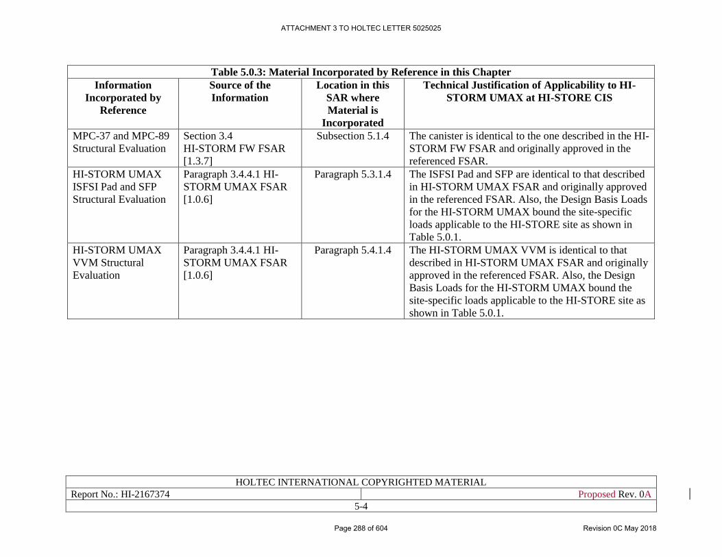
HOLTEC INTERNATIONAL COPYRIGHTED MATERIAL
Report No.: HI-2167374 Proposed Rev. 0A
5-4
Table 5.0.3: Material Incorporated by Reference in this Chapter
Information
Incorporated by
Reference
Source of the
Information
Location in this
SAR where
Material is
Incorporated
Technical Justification of Applicability to HI-
STORM UMAX at HI-STORE CIS
MPC-37 and MPC-89
Structural Evaluation
Section 3.4
HI-STORM FW FSAR
[1.3.7]
Subsection 5.1.4 The canister is identical to the one described in the HI-
STORM FW FSAR and originally approved in the
referenced FSAR.
HI-STORM UMAX
ISFSI Pad and SFP
Structural Evaluation
Paragraph 3.4.4.1 HI-
STORM UMAX FSAR
[1.0.6]
Paragraph 5.3.1.4 The ISFSI Pad and SFP are identical to that described
in HI-STORM UMAX FSAR and originally approved
in the referenced FSAR. Also, the Design Basis Loads
for the HI-STORM UMAX bound the site-specific
loads applicable to the HI-STORE site as shown in
Table 5.0.1.
HI-STORM UMAX
VVM Structural
Evaluation
Paragraph 3.4.4.1 HI-
STORM UMAX FSAR
[1.0.6]
Paragraph 5.4.1.4 The HI-STORM UMAX VVM is identical to that
described in HI-STORM UMAX FSAR and originally
approved in the referenced FSAR. Also, the Design
Basis Loads for the HI-STORM UMAX bound the
site-specific loads applicable to the HI-STORE site as
shown in Table 5.0.1.
ATTACHMENT 3 TO HOLTEC LETTER 5025025
Page 288 of 604 Revision 0C May 2018
HOLTEC INTERNATIONAL COPYRIGHTED MATERIAL
Report No.: HI-2167374 Proposed Rev. 0A
5-5
5.1 CONFINEMENT STRUCTURES, SYSTEMS, AND COMPONENTS
The only confinement SSC that is utilized at the HI-STORE CIS facility is the Multi-Purpose
Canister (MPC). There are two types of MPCs that are permitted to be stored at the HI-STORE
site, namely MPC-37 and MPC-89, both of which have been previously licensed by the NRC as
part of the HI-STORM FW dry storage system (Docket # 72-1032). The structural design basis for
MPC-37 and MPC-89, which are used to store PWR and BWR fuel, respectively, are described in
complete detail in Chapters 2 and 3 of the HI-STORM FW FSAR [1.3.7]. A brief summary of their
structural design basis is provided below.
5.1.1 Description of Structural Design
The MPC enclosure vessels are cylindrical weldments with identical and fixed outside diameters.
Each MPC is an assembly consisting of a honeycomb fuel basket, a baseplate, a canister shell, a
lid, and a closure ring. The number of SNF storage locations in an MPC depends on the type of
fuel assembly (PWR or BWR) to be stored in it. The required characteristics of the fuel assemblies
to be stored in the MPC are limited in accordance with Section 4.1 of the SAR.
The MPC enclosure vessel is a fully welded enclosure, which provides the confinement for the
stored fuel and radioactive material. The MPC baseplate and shell are made of stainless steel. The
lid is a two-piece construction, with the top structural portion made of Alloy X. The confinement
boundary is defined by the MPC baseplate, shell, lid, port covers, and closure ring. Drawings for
the MPCs are provided in Section 1.5.
The MPC-37 and MPC-89 fuel baskets are assembled using interlocking Metamic-HT panels, as
shown in the Licensing Drawings in Section 1.5.
5.1.2 Design Criteria
The MPC is classified as important-to-safety. The MPC structural components include the fuel
basket and the enclosure vessel. The MPC enclosure vessel is designed and fabricated as a Class
1 pressure vessel in accordance with Section III, Subsection NB of the ASME Code, with certain
necessary alternatives, as discussed in Section 2.2 of [1.3.7]. The MPC fuel basket is a non-Code
Compliance with the ASME Code, with respect to the design and fabrication of the MPC, and the
associated justification are discussed in Section 2.2 of [1.3.7]. The MPC design is analyzed for all
design basis normal, off-normal, and postulated accident conditions, as defined in Section 2.2 of
[1.3.7], which bound the conditions at the HI-STORE site.
5.1.3 Material Properties
The MPC shell, baseplate and lid are made of stainless steel (Alloy X, see Appendix 1.A of
[1.3.7]). The properties for Alloy X are listed in Table 3.3.1 of the HI-STORM FW FSAR [1.3.7].
The minimum strength properties for Metamic-HT, which is used to fabricate the fuel baskets, are
provided in Table 1.2.8 of the HI-STORM FW FSAR [1.3.7].
ATTACHMENT 3 TO HOLTEC LETTER 5025025
Page 289 of 604 Revision 0C May 2018
HOLTEC INTERNATIONAL COPYRIGHTED MATERIAL
Report No.: HI-2167374 Proposed Rev. 0A
5-6
5.1.4 Structural Analyses
The structural analyses for the MPC for all design basis normal, off-normal, and postulated
accident conditions are documented in Chapter 3 of the HI-STORM FW FSAR [1.3.7] and further
supplemented by the seismic response analysis of the MPC inside the HI-STORM UMAX
presented in Subparagraph 3.4.4.1.2 of the HI-STORM UMAX FSAR [1.0.6].
The fatigue evaluations for the HI-STORM FW and HI-STORM UMAX Systems, which are found
in Subsection 3.1.2.5 of their respective FSARs, remain valid for the proposed 40-year storage
term at the HI-STORE CIS Facility. This is because the passive nature and the large thermal inertia
of these storage systems protect the MPC enclosure vessel from significant stress cycling. In fact,
the amplitude of the stress cycles is well below the endurance limit of the stainless steel MPC,
which means that the MPC has infinite fatigue life under long-term storage conditions.
Moreover, as shown in Table 6.3.1 of the HI-STORE SAR, the maximum MPC heat loads and the
ambient temperature conditions applicable to the HI-STORE CIS Facility are less demanding than
the corresponding values for which the HI-STORM UMAX System is certified. This reduces stress
amplitudes in the MPC at the HI-STORE CIS Facility and ensures that the ASME Code required
fatigue evaluations that were originally performed for the UMAX and FW systems remain valid
for 40 years of storage at the HI-STORE CIS Facility.
ATTACHMENT 3 TO HOLTEC LETTER 5025025
Page 290 of 604 Revision 0C May 2018
HOLTEC INTERNATIONAL COPYRIGHTED MATERIAL
Report No.: HI-2167374 Proposed Rev. 0A
5-7
5.2 POOL AND POOL CONFINEMENT FACILITIES
There are no pools at the HI-STORE CIS facility.
ATTACHMENT 3 TO HOLTEC LETTER 5025025
Page 291 of 604 Revision 0C May 2018
HOLTEC INTERNATIONAL COPYRIGHTED MATERIAL
Report No.: HI-2167374 Proposed Rev. 0A
5-8
5.3 REINFORCED CONCRETE STRUCTURES
The HI-STORE CIS facility includes the following reinforced concrete structures:
• HI-STORM UMAX ISFSI Pad and Support Foundation Pad (SFP)
• Cask Transfer Building (CTB) Slab
• Canister Transfer Facility (CTF) Foundation
Each of these components is discussed in more detail, including their description, design criteria,
material properties, and structural analyses, in the following subsections.
5.3.1 HI-STORM UMAX ISFSI Pad and Support Foundation Pad
5.3.1.1 Description of Structural Design
The HI-STORM UMAX ISFSI pad and Support Foundation Pad (SFP) are integral parts of the
HI-STORM UMAX underground dry storage system, which has already been licensed in
accordance with 10CFR72 requirements under NRC Docket # 72-1040. As described in Section
1.2 of this SAR, the structural performance objectives for the ISFSI pad are to provide a riding
surface for the cask transporter and to serve as a missile barrier. The SFP is the foundation mat for
the HI-STORM UMAX structure, and it also serves as the resting surface for the VVM array. As
shown on the Licensing Drawing in Section 1.5, the SFP is a continuous concrete pad of uniform
thickness, whereas the ISFSI pad fills the interstitial space between the VVM at the top of grade
level.
5.3.1.2 Design Criteria
The SFP and the ISFSI pad are categorized as important-to-safety (ITS) structures as indicated in
Table 4.2.1. ACI 318-05 [5.3.1] is specified as the reference code for the design qualification of
the SFP and the ISFSI pad using the load combinations specified in Table 2.4.3 of [1.0.6].
5.3.1.3 Material Properties
The ISFSI pad and SFP are reinforced concrete structures with their properties defined in Table
2.3.2 of the HI-STORM UMAX FSAR [1.0.6].
5.3.1.4 Structural Analysis
The seismic and structural qualification of the HI-STORM UMAX storage system, including the
ISFSI pad and SFP, is performed in Chapter 3 of [1.0.6]. As shown in Table 5.0.1 above, the design
basis loads analyzed in the HI-STORM UMAX FSAR completely bound the site-specific loads
applicable to the HI-STORE site, and therefore no new structural analysis is required to qualify
the ISFSI pad or the SFP for this application.
ATTACHMENT 3 TO HOLTEC LETTER 5025025
Page 292 of 604 Revision 0C May 2018
HOLTEC INTERNATIONAL COPYRIGHTED MATERIAL
Report No.: HI-2167374 Proposed Rev. 0A
5-9
5.3.2 Cask Transfer Building Slab
5.3.2.1 Description of Structural Design
The Cask Transfer Building (CTB) slab is a reinforced concrete slab, which serves as the structural
foundation for the railway and the CTB Crane, provides a riding surface for the VCT inside the
CTB, and acts as laydown area for the HI-TRAC CS and other ancillary equipment. The general
layout and key dimensions of the CTB slab are shown on the Licensing Drawing in Section 1.5.
5.3.2.2 Design Criteria
The structural design criteria for the CTB slab, including the governing load combinations, are
provided in Subsection 4.6.2 of this SAR.
5.3.2.3 Material Properties
The material properties for the CTB slab are summarized in Table 5.3.1.
5.3.2.4 Structural Analysis
The analysis of the CTB slab is carried out using classical solutions for a slab on grade, which are
obtained from [5.3.2], to determine the internal forces and moments acting on the CTB slab for
the governing load combinations in Subsection 4.6.2.
The analysis of the slab considers the live loads associated with the freestanding HI-TRAC CS,
the VCT, the CTB crane, the tilt frame (loaded with HI-STAR 190 with impact limiters), and the
loaded rail car. The load acting on the CTB slab due to the CTB crane and the rail car are applied
as concentrated forces at the wheel locations. The VCT load is applied as a uniform distributed
pressure over the footprint area of its tracks/wheels. The load on the tilt frame assembly is also
applied as a uniformly distributed pressure.
For the seismic load combination, the weight of each component (e.g., VCT) is amplified by the
vertical ZPA for the Design Basis Earthquake (DBE), which is given in Table 4.3.3. The use of
the ZPA value is justified since the DBE is a low-intensity earthquake that does not cause any of
the above mentioned equipment to rock/uplift (i.e., no incipient tipping).
The calculated results for each load combination are compared with the ACI Code compliant
section capacities to demonstrate the structural adequacy of the CTB slab. All calculated safety
factors for the CTB slab are greater than 1.0 as shown in Table 5.3.2. The complete details of the
CTB slab analysis are provided in the Structural Calculation Package [5.4.6].
5.3.3 Canister Transfer Facility Foundation
5.3.3.1 Description of Structural Design
The Canister Transfer Facility (CTF) is a below-ground structure used to carry out vertical MPC
transfers from the transport cask to the HI-TRAC CS (or vice versa). The design enables a transport
cask to be lowered into the CTF cavity (see Figure 3.1.1 (g)). With the transport cask in place, the
HI-TRAC CS is then positioned above the CTF cavity opening and anchor bolts are installed to
secure the HI-TRAC CS to the CTB slab at the CTF location, after which the MPC can be vertically
lifted from the transport cask into the HI-TRAC CS using the VCT. The general layout and key
dimensions of the CTF are shown on the Licensing Drawing in Section 1.5.
ATTACHMENT 3 TO HOLTEC LETTER 5025025
Page 293 of 604 Revision 0C May 2018
HOLTEC INTERNATIONAL COPYRIGHTED MATERIAL
Report No.: HI-2167374 Proposed Rev. 0A
5-10
At the base of the CTF cavity is a reinforced concrete slab that acts as the supporting surface for
the transport cask during transfer operations. This below-grade slab is referred to as the CTF
foundation, and its construction is identical to the CTB slab with respect to thickness, strength,
and reinforcement details.
5.3.3.2 Design Criteria
The design criteria for the CTF foundation, which is an ITS component, are the same as the criteria
for the CTB slab, which are provided in Subsection 4.6.2.
5.3.3.3 Material Properties
The material properties for the CTF foundation are identical to those for the CTB slab, which are
given in Table 5.3.1.
5.3.3.4 Structural Analysis
The results for the structural analysis of the CTB slab, which are discussed above in Paragraph
5.3.2.4, are also bounding for the CTF foundation for the following reasons:
a) The construction of the CTB slab and the CTF foundation are identical in terms of their
thickness, reinforcement details, and minimum strength properties.
b) The bounding weight of a loaded HI-TRAC CS (which rests vertically on the CTB slab),
used in the structural evaluation [5.4.6], is greater than the bounding weight of a loaded
HI-STAR 190 transport cask without impact limiters (which rests vertically on CTF
foundation). See Table 5.0.2 for bounding weight comparison.
c) The contact footprint of the HI-TRAC CS alignment shield ring is smaller than that of the
HI-STAR 190 bottom forging. The outer diameter is nearly equal but the alignment shield
ring is an annular ring whereas the HI-STAR 190 bottom forging is a solid cylinder.
Based on the above, the minimum calculated safety factor for the CTB slab given in Table 5.3.2
is also a lower bound safety factor for the CTF foundation.
ATTACHMENT 3 TO HOLTEC LETTER 5025025
Page 294 of 604 Revision 0C May 2018
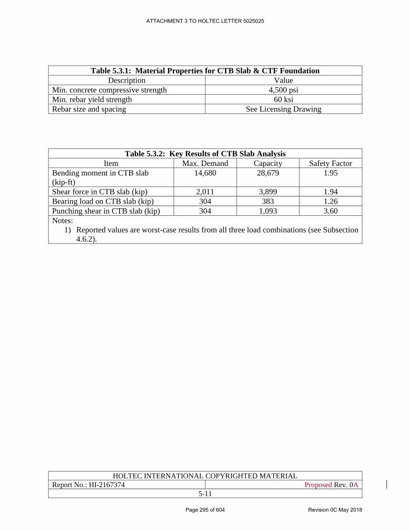
HOLTEC INTERNATIONAL COPYRIGHTED MATERIAL
Report No.: HI-2167374 Proposed Rev. 0A
5-11
Table 5.3.1: Material Properties for CTB Slab & CTF Foundation
Description Value
Min. concrete compressive strength 4,500 psi
Min. rebar yield strength 60 ksi
Rebar size and spacing See Licensing Drawing
Table 5.3.2: Key Results of CTB Slab Analysis
Item Max. Demand Capacity Safety Factor
Bending moment in CTB slab
(kip-ft)
14,680 28,679 1.95
Shear force in CTB slab (kip) 2,011 3,899 1.94
Bearing load on CTB slab (kip) 304 383 1.26
Punching shear in CTB slab (kip) 304 1,093 3.60
Notes:
1) Reported values are worst-case results from all three load combinations (see Subsection
4.6.2).
ATTACHMENT 3 TO HOLTEC LETTER 5025025
Page 295 of 604 Revision 0C May 2018
HOLTEC INTERNATIONAL COPYRIGHTED MATERIAL
Report No.: HI-2167374 Proposed Rev. 0A
5-12
5.4 OTHER SSCs IMPORTANT TO SAFETY
The HI-STORE CIS facility includes the following other SSCs that are classified as important to
safety:
• HI-STORM UMAX Vertical Ventilated Module (VVM)
• HI-TRAC CS
• Cask Transfer Building Crane
• Transport Cask Lift Yoke
• MPC Lift Attachment
• Special Lifting Devices
Each of these components is discussed in more detail, including their description, design criteria,
material properties, and structural analyses, in the following subsections.
5.4.1 HI-STORM UMAX VVM
5.4.1.1 Description of Structural Aspects
The HI-STORM UMAX VVM is a central component of the HI-STORM UMAX dry storage
system, which has been previously licensed in accordance with 10CFR72 requirements under NRC
Docket # 72-1040. The VVM provides for storage of the MPC in a vertical configuration inside a
subterranean cylindrical cavity entirely below the top-of-grade (TOG) of the ISFSI pad. The VVM
is comprised of the Cavity Enclosure Container (CEC) and the Closure Lid, which are both shown
on the Licensing Drawing in Section 1.5. A full description of the VVM, including its
subcomponents, is provided in Section 1.2 of the HI-STORM UMAX FSAR [1.0.6]. The HI-
STORM UMAX VVM is licensed as a variable height system in [1.0.6]. For the HI-STORE CIS
facility, however, there will be one uniform depth for all VVMs as shown on the Licensing
Drawing in Section 1.5. The HI-STORM UMAX FSAR also provides for multiple design options
with respect to the seismic restraints and the closure lid design. The specific set of options selected
for the HI-STORE CIS facility are shown on the Licensing Drawing in Section 1.5. This design
variant of the HI-STORM UMAX, which is to be deployed at the HI-STORE CIS facility, is
referred to as the HI-STORM UMAX Version C.
5.4.1.2 Design Criteria
To serve its intended function, the HI-STORM UMAX VVM, including the CEC and Closure Lid,
shall ensure physical protection, biological shielding, and allow the retrieval of the MPC under all
conditions of storage (10 CFR 72.122(l)). Because the VVM is an in-ground structure, drops and
tip-over of the VVM are not credible events and, therefore, do not warrant analysis. The design
bases and criteria for the VVM are fully defined in Chapter 2 of the HI-STORM UMAX FSAR
[1.0.6]. The load cases germane to establishing the structural adequacy of the VVM pursuant to 10
CFR 72.24(c) are compiled in Table 2.4.1 of [1.0.6].
ATTACHMENT 3 TO HOLTEC LETTER 5025025
Page 296 of 604 Revision 0C May 2018
HOLTEC INTERNATIONAL COPYRIGHTED MATERIAL
Report No.: HI-2167374 Proposed Rev. 0A
5-13
5.4.1.3 Material Properties
The material properties for the VVM are provided in Section 3.3 of the HI-STORM UMAX FSAR
[1.0.6] in conjunction with the Licensing Drawing in Section 1.5.
5.4.1.4 Structural Analysis
The design basis structural analyses for the VVM for all applicable normal, off-normal, and
accident loadings are presented in Chapter 3 of the HI-STORM UMAX FSAR [1.0.6]. As shown
in Table 5.0.1 above, the design basis loads analyzed in the HI-STORM UMAX FSAR completely
bound the site-specific loads applicable to the HI-STORE site, and therefore minimal structural
analyses are required to qualify the VVM for this application.
The only loading event for the VVM that is not generically analyzed in the HI-STORM UMAX
FSAR is a postulated earthquake during MPC transfer operations at the VVM, wherein the HI-
TRAC CS is vertically stacked on top of the VVM and securely fastened in place at four anchor
bolt locations. The analysis of this stack-up configuration is performed herein using the time
history analysis method implemented in LS-DYNA [5.4.2]. The finite element model used for this
analysis is shown in Figure 5.4.1.
[
PROPRIETARY INFORMATION WITHHELD IN ACCORDANCE WITH 10CFR2.390
]
ATTACHMENT 3 TO HOLTEC LETTER 5025025
Page 297 of 604 Revision 0C May 2018
HOLTEC INTERNATIONAL COPYRIGHTED MATERIAL
Report No.: HI-2167374 Proposed Rev. 0A
5-14
5.4.2 HI-TRAC CS
5.4.2.1 Description of Structural Aspects
The HI-TRAC CS is a steel and concrete transfer cask, which is used for all on-site canister
transfers. It has a cylindrical body delimited by carbon steel inner and outer shells with densified
concrete occupying the space between the shells. The HI-TRAC CS has two trunnions near the top
of the cask for lifting, and two rotation trunnions near its base for upending (or down ending) the
cask. The bottom lid of the HI-TRAC CS, which is also referred to as the shield gate, is split into
two halves such that they can be slid open in a symmetric manner to allow the MPC to pass through
the opening (see Figure 1.2.3a). A complete description of the HI-TRAC CS is provided in
Subsection 1.2.4.
5.4.2.2 Design Criteria
The design criteria for the HI-TRAC CS, which is an ITS component, are fully provided in
Subsection 4.3.3.
The structural steel components of the HI-TRAC CS are designed to meet the stress limits of
Section III, Subsection NF of the ASME Code [4.5.1] for all operating modes. The embedded
trunnions for lifting and handling of the transfer cask are designed in accordance with the
requirements of NUREG-0612 [1.2.7] for interfacing lift points.
Table 4.3.4 lists the loading scenarios for HI-TRAC CS for which its structural qualification must
be performed.
5.4.2.3 Material Properties
The fabrication materials for the HI-TRAC CS are the same as those for the HI-STORM FW and
the HI-TRAC VW. Therefore, the material properties for the HI-TRAC CS can be obtained from
the summary tables in Section 3.3 of the HI-STORM FW FSAR [1.3.7], which are sourced from
the Section II, Part D of ASME Code [4.6.3].
5.4.2.4 Structural Analysis
The loads on the HI-TRAC CS that are structurally significant are listed in Table 4.3.4, and the
structural analysis for each of these loads is described below.
5.4.2.4.1 Lifting Analysis
[
PROPRIETARY INFORMATION WITHHELD IN ACCORDANCE WITH 10CFR2.390
]
ATTACHMENT 3 TO HOLTEC LETTER 5025025
Page 298 of 604 Revision 0C May 2018
HOLTEC INTERNATIONAL COPYRIGHTED MATERIAL
Report No.: HI-2167374 Proposed Rev. 0A
5-15
[
PROPRIETARY INFORMATION WITHHELD IN ACCORDANCE WITH 10CFR2.390
]
The results for the above lifting analyses are summarized in Table 5.4.2, which shows that all
calculated stresses are less than their applicable stress limits. The complete details of the HI-TRAC
CS lifting analysis are provided in the Structural Calculation Package [5.4.6].
5.4.2.4.2 Seismic Analysis at CTF
The seismic analysis of the HI-TRAC CS while it is mounted atop a HI-STORM UMAX VVM is
discussed in Subsection 5.4.1.4, and the results are summarized in Table 5.4.1. The anchorage
design used to secure the HI-TRAC CS to the CTF is the same design used to anchor the HI-TRAC
CS at a HI-STORM UMAX VVM location. The only difference between stack-up configurations
at the CTF versus the HI-STORM UMAX VVM is the anchor bolts used to secure the HI-TRAC
CS are longer for the latter configuration. The longer free length of the bolts introduces more
flexibility into the system, which in turn may lead to larger rocking displacements and internal
loads acting on the stack under seismic conditions. In light of this, plus the fact that the stack-up
analysis for the HI-STORM UMAX VVM is conservatively performed using the most limiting
earthquake condition (i.e., DECE), the results for the HI-TRAC CS in Table 5.4.1 are also
bounding for the stack-up configuration at the CTF.
5.4.2.4.3 Tornado Missile Analysis
When the HI-TRAC CS is in use at the HI-STORE site, it is potentially exposed to tornado
generated missiles. Although the threat of a tornado is relatively low at the HI-STORE site (see
Section 2.3), the HI-TRAC CS is conservatively analyzed for the same tornado missiles as
previously analyzed for the HI-STORM FW system and the HI-STORM UMAX system. These
bounding tornado missiles are listed in Table 2.7.2.
[
PROPRIETARY INFORMATION WITHHELD IN ACCORDANCE WITH 10CFR2.390
]
ATTACHMENT 3 TO HOLTEC LETTER 5025025
Page 299 of 604 Revision 0C May 2018
HOLTEC INTERNATIONAL COPYRIGHTED MATERIAL
Report No.: HI-2167374 Proposed Rev. 0A
5-16
The complete details of the tornado missile analysis are provided in the Structural Calculation
Package [5.4.6].
5.4.2.4.4 Seismic Stability Analysis of Freestanding HI-TRAC CS
The general stability of a freestanding HI-TRAC CS (empty and fully loaded) under the SSE is
evaluated for the possibility of incipient tipping and sliding, where simple dynamic equations are
formulated based on force and moment equilibrium. Table 5.4.7 summarizes both the bounding
parameters used as input to the seismic stability analysis and the results. As seen from the table,
the cask does not uplift or slide under the SSE event. A similar analysis has also been performed
for the HI-STAR 190, and the results are likewise summarized in Table 5.4.7.
5.4.2.4.5 CTB Collapse Analysis
As discussed in Section 4.6.1, the walls and roof structure of the CTB are designed to meet the
requirements of IBC [4.6.4] and ASCE 7-10 [4.6.2], and they are designated as not important to
safety (NITS). This means that they are not designed to withstand seismic or tornado loads.
Therefore, HI-TRAC CS (as well as HI-STAR 190) has been structurally analyzed to evaluate the
damage due to a potential building collapse. [
PROPRIETARY INFORMATION WITHHELD IN ACCORDANCE WITH 10CFR2.390
]
The complete details of the CTB collapse analysis are provided in the Structural Calculation
Package [5.4.6].
5.4.2.4.6 Fatigue Evaluation
The HI-TRAC CS will be used repeatedly at the HI-STORE CIS facility to transfer canisters from
arriving transport casks to VVM storage cavities. As a result, the HI-TRAC CS will be subject to
both thermal and mechanical cyclic loading, which must be evaluated from a fatigue life
standpoint. A fatigue life evaluation for all load bearing members of HI-TRAC CS has been
performed in [5.4.6], and the results are presented in Table 5.4.8. The maximum stress in the
trunnions is conservatively set at the allowable stress limit per [1.2.7] times a stress concentration
ATTACHMENT 3 TO HOLTEC LETTER 5025025
Page 300 of 604 Revision 0C May 2018
HOLTEC INTERNATIONAL COPYRIGHTED MATERIAL
Report No.: HI-2167374 Proposed Rev. 0A
5-17
factor of 4.0 for the material. The use of stress concentration factor of 4.0 is consistent with HI-
STAR 100 SAR [1.3.5]. The maximum stress in all other load bearing members of HI-TRAC CS,
designed to stress limits in [4.5.1], is conservatively set at the ultimate strength of the material.
The fatigue life of all load bearing materials is calculated by comparing the maximum stress value
with the material cycle life curves defined in Appendix I of ASME Code [17.3.2]. A safety factor
of 2.0 on the permissible loading cycles is imposed for additional conservatism per Subsection
4.5.3.9.
5.4.3 Cask Transfer Building Crane
5.4.3.1 Description of Structural Aspects
The Cask Transfer Building (CTB) Crane consists of a gantry crane, trolley, and hoist(s). The CTB
Crane is electrically driven and rides on crane rails, which are mounted to the CTB slab in the
Cask Receiving Area. The trolley rides on crane rails mounted to the top of the crane girders and
has at least one electric wire rope hoist for load lifting. The hoist hook will be used to lift various
loads and shall interface with the required rigging and below the hook lifting devices as required
for the process. Figure 3.1.1 (b-c) is an illustration of the CTB Crane loading/unloading a transport
package to/from a transport vehicle.
5.4.3.2 Design Criteria
The CTB Crane shall be a single failure proof load handling device designed and built in
accordance with the provisions of ASME NOG-1 [3.0.1]. The design criteria and operational
requirements for the CTB Crane are further discussed in Subsection 4.5.2 of this SAR.
The applicable Design Basis loadings on the CTB Crane are set down in Table 4.5.1.
5.4.3.3 Structural Analysis
The structural analysis of the CTB Crane shall demonstrate compliance with the applicable
requirements of ASME NOG-1 for the specified loadings in Table 4.5.1.
5.4.4 Transport Cask Lift Yoke
5.4.4.1 Description of Structural Aspects
The Transport Cask Lifting Device is used to lift the HI-STAR 190 transport cask inside the CTB.
As shown on the Licensing Drawing in Section 1.5, the Transport Cask Lifting Device has two lift
arms that connect to the pair of lifting trunnions on the HI-STAR 190 and a main strongback
assembly that connects to the CTB Crane hook.
5.4.4.2 Design Criteria
The design criteria that apply to lifting devices are fully described in Section 4.5. The Transport
Cask Lift Yoke is a non-redundant special lifting device, which is designed to meet the increased
safety factors per ANSI N14.6 [1.2.4].
5.4.4.3 Material Properties
As shown on the Licensing Drawing in Section 1.5, the major structural components of the
Transport Cask Lift Yoke are the strongback plates, the lift arms, the actuator plates, the main pins,
ATTACHMENT 3 TO HOLTEC LETTER 5025025
Page 301 of 604 Revision 0C May 2018
HOLTEC INTERNATIONAL COPYRIGHTED MATERIAL
Report No.: HI-2167374 Proposed Rev. 0A
5-18
and the actuator pins. The strongback plates, lift arms, and actuator plates are fabricated from
high-strength alloy steel (A514 or equivalent). The main pins and actuator pins are fabricated from
hardened nickel alloy bar material (SB-637 N07718). The minimum strength properties for these
components are obtained directly from the applicable ASTM specification or from Section II, Part
D of the ASME Code [4.6.3].
5.4.4.4 Structural Analysis
The load bearing members of the Transport Cask Lift Yoke are analyzed using a combination of
formulae from ASME BTH-1 [5.4.3] and strength of materials principles. The lifted load
considered in the analysis is equal to the bounding weight of the loaded HI-STAR 190 transport
cask from Table 5.0.2. The lifted load and the self-weight of the lifting device are further amplified
by 15% to account for dynamic effects in accordance with the guidance in CMAA-70 [4.5.2] for
low speed lifts. The results of the structural analysis for the Transport Cask Lift Yoke are
summarized in Table 5.4.4, which shows that all calculated safety factors are greater than 1.0. The
complete details of the structural analysis of the Transport Cask Lift Yoke are provided in the
Structural Calculation Package [5.4.6].
5.4.5 MPC Lift Attachment
5.4.5.1 Description of Structural Aspects
The MPC Lift Attachment is a one-piece lifting device (or lug) that is bolted directly to threaded
anchor locations on the top surface of the MPC closure lid using a total of eight bolts (see Licensing
Drawing in Section 1.5). The MPC Lift Attachment allows raising or lowering of the MPC during
canister transfer operations using either the CTB Crane or the VCT.
5.4.5.2 Design Criteria
The design criteria that apply to lifting devices are fully described in Section 4.5. The MPC Lift
Attachment is a non-redundant special lifting device, which is designed to meet the increased
safety factors per ANSI N14.6 [1.2.4].
5.4.5.3 Material Properties
As described above, the MPC Lift Attachment consists of the lifting lug and eight attachment bolts.
The lifting lug is fabricated from an alloy steel forging (A336-F6NM). The attachment bolts are
fabricated from hardened nickel alloy bar material (SB-637 N07718). The minimum strength
properties for these components are obtained directly from the applicable ASTM specification or
from Section II, Part D of the ASME Code [4.6.3].
5.4.5.4 Structural Analysis
The load bearing members of the MPC Lift Attachment are analyzed using strength of materials
principles together with formulae from ASME BTH-1 [5.4.3]. The lifted load considered in the
analysis is equal to the bounding weight of a loaded MPC from Table 5.0.2. The lifted load and
the self-weight of the lifting device are further amplified by 15% to account for dynamic effects
in accordance with the guidance in CMAA-70 [4.5.2] for low speed lifts. The results of the
structural analysis for the MPC Lift Attachment are summarized in Table 5.4.5, which shows that
all calculated safety factors are greater than 1.0. The complete details of the structural analysis of
the MPC Lift Attachment are provided in the Structural Calculation Package [5.4.6].
ATTACHMENT 3 TO HOLTEC LETTER 5025025
Page 302 of 604 Revision 0C May 2018
HOLTEC INTERNATIONAL COPYRIGHTED MATERIAL
Report No.: HI-2167374 Proposed Rev. 0A
5-19
5.4.6 Other Special Lifting Devices
5.4.6.1 Description of Structural Aspects
In addition to the Transport Cask Lift Yoke and MPC Lift Attachment discussed in the preceding
subsections, there are other special lifting devices that will be used to connect the cask or canister
to the CTB Crane or VCT at the HI-STORE CIS facility. These other special lifting devices
include:
• HI-TRAC CS Lift Yoke
• HI-TRAC CS Lift Link
• Transport Cask Horizontal Lift Beam
• MPC Lifting Device Extension
All special lifting devices that will be used at the HI-STORE CIS facility are shown on the
Licensing Drawings in Section 1.5.
5.4.6.2 Design Criteria
The design criteria that apply to lifting devices are fully described in Section 4.5. Special lifting
devices are designed to meet the increased safety factors per ANSI N14.6 [1.2.4].
5.4.6.3 Material Properties
The fabrication materials for the special lifting devices listed above are specified on the Licensing
Drawings in Section 1.5. The minimum strength properties for these materials are obtained directly
from the applicable ASTM specification or from Section II, Part D of the ASME Code [4.6.3] in
accordance with the Licensing Drawings.
5.4.6.4 Structural Analysis
5.4.6.4.1 Lifting Analysis
The load bearing members of special lifting devices are analyzed using a combination of methods,
including the finite element approach, formulae from ASME BTH-1 [5.4.3], and strength of
materials principles. The lifted loads considered in the analyses are equal to the bounding weights
of the loaded HI-STAR 190 transport cask, the loaded MPC, or the loaded HI-TRAC CS from
Table 5.0.2, as applicable. The lifted load and the self-weight of the lifting device are further
amplified by 15% to account for dynamic effects in accordance with the guidance in CMAA-70
[4.5.2] for low speed lifts. The minimum calculated safety factors for the special lifting devices,
other than the Transport Cask Lift Yoke and the MPC Lift Attachment, are summarized in Table
5.4.6. The complete details of the structural analysis of the special lifting devices are provided in
the Structural Calculation Package [5.4.6].
5.4.6.4.2 Fatigue Evaluation
The special lifting devices will be used repeatedly at the HI-STORE CIS facility to transfer
canisters from arriving transport casks to VVM storage cavities. As a result, the special lifting
devices will be subject to both thermal and mechanical cyclic loading, which must be evaluated
from a fatigue life standpoint. A fatigue life evaluation for all special lifting devices has been
ATTACHMENT 3 TO HOLTEC LETTER 5025025
Page 303 of 604 Revision 0C May 2018
HOLTEC INTERNATIONAL COPYRIGHTED MATERIAL
Report No.: HI-2167374 Proposed Rev. 0A
5-20
performed in [5.4.6], and the results are presented in Table 5.4.9. The maximum stress in the
special lifting devices is conservatively set at the allowable stress limit per [1.2.4] times a stress
concentration factor of 4.0 for the material. The use of stress concentration factor of 4.0 is
consistent with HI-STAR 100 SAR [1.3.5]. The fatigue life of all load bearing materials is
calculated by comparing the maximum stress value with the material cycle life curves defined in
Appendix I of ASME Code [17.3.2]. A safety factor of 2.0 on the permissible loading cycles is
imposed for additional conservatism per Subsection 4.5.3.9.
ATTACHMENT 3 TO HOLTEC LETTER 5025025
Page 304 of 604 Revision 0C May 2018

HOLTEC INTERNATIONAL COPYRIGHTED MATERIAL
Report No.: HI-2167374 Proposed Rev. 0A
5-21
Table 5.4.1: [PROPRIETARY INFORMATION WITHHELD IN ACCORDANCE
WITH 10CFR2.390]
ATTACHMENT 3 TO HOLTEC LETTER 5025025
Page 305 of 604 Revision 0C May 2018
HOLTEC INTERNATIONAL COPYRIGHTED MATERIAL
Report No.: HI-2167374 Proposed Rev. 0A
5-22
Table 5.4.2: [PROPRIETARY INFORMATION WITHHELD IN ACCORDANCE
WITH 10CFR2.390]
Table 5.4.3: [PROPRIETARY INFORMATION WITHHELD IN ACCORDANCE
WITH 10CFR2.390]
ATTACHMENT 3 TO HOLTEC LETTER 5025025
Page 306 of 604 Revision 0C May 2018
HOLTEC INTERNATIONAL COPYRIGHTED MATERIAL
Report No.: HI-2167374 Proposed Rev. 0A
5-23
Table 5.4.4: [PROPRIETARY INFORMATION WITHHELD IN ACCORDANCE
WITH 10CFR2.390]
ATTACHMENT 3 TO HOLTEC LETTER 5025025
Page 307 of 604 Revision 0C May 2018
HOLTEC INTERNATIONAL COPYRIGHTED MATERIAL
Report No.: HI-2167374 Proposed Rev. 0A
5-24
Table 5.4.5: [PROPRIETARY INFORMATION WITHHELD IN ACCORDANCE
WITH 10CFR2.390]
Table 5.4.6: [PROPRIETARY INFORMATION WITHHELD IN ACCORDANCE
WITH 10CFR2.390]
ATTACHMENT 3 TO HOLTEC LETTER 5025025
Page 308 of 604 Revision 0C May 2018
HOLTEC INTERNATIONAL COPYRIGHTED MATERIAL
Report No.: HI-2167374 Proposed Rev. 0A
5-25
Table 5.4.7: [PROPRIETARY INFORMATION WITHHELD IN ACCORDANCE
WITH 10CFR2.390]
ATTACHMENT 3 TO HOLTEC LETTER 5025025
Page 309 of 604 Revision 0C May 2018
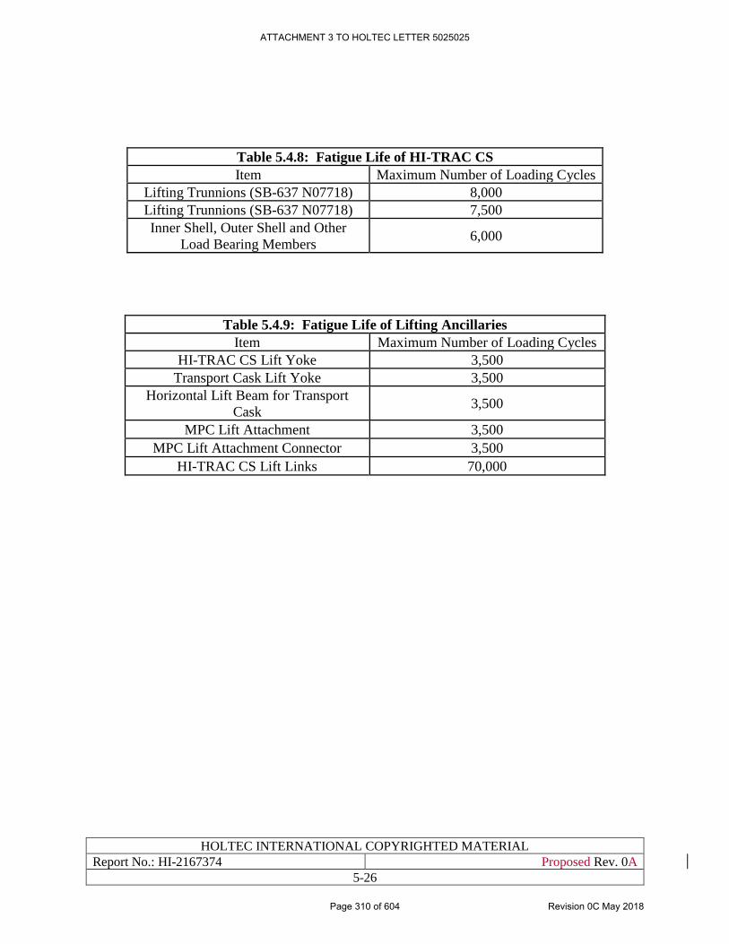
HOLTEC INTERNATIONAL COPYRIGHTED MATERIAL
Report No.: HI-2167374 Proposed Rev. 0A
5-26
Table 5.4.8: Fatigue Life of HI-TRAC CS
Item Maximum Number of Loading Cycles
Lifting Trunnions (SB-637 N07718) 8,000
Lifting Trunnions (SB-637 N07718) 7,500
Inner Shell, Outer Shell and Other
Load Bearing Members 6,000
Table 5.4.9: Fatigue Life of Lifting Ancillaries
Item Maximum Number of Loading Cycles
HI-TRAC CS Lift Yoke 3,500
Transport Cask Lift Yoke 3,500
Horizontal Lift Beam for Transport
Cask 3,500
MPC Lift Attachment 3,500
MPC Lift Attachment Connector 3,500
HI-TRAC CS Lift Links 70,000
ATTACHMENT 3 TO HOLTEC LETTER 5025025
Page 310 of 604 Revision 0C May 2018
HOLTEC INTERNATIONAL COPYRIGHTED MATERIAL
Report No.: HI-2167374 Proposed Rev. 0A
5-27
Figure 5.4.1: [PROPRIETARY INFORMATION WITHHELD IN ACCORDANCE WITH
10CFR2.390]
ATTACHMENT 3 TO HOLTEC LETTER 5025025
Page 311 of 604 Revision 0C May 2018
HOLTEC INTERNATIONAL COPYRIGHTED MATERIAL
Report No.: HI-2167374 Proposed Rev. 0A
5-28
Figure 5.4.2: [PROPRIETARY INFORMATION WITHHELD IN ACCORDANCE WITH
10CFR2.390]
ATTACHMENT 3 TO HOLTEC LETTER 5025025
Page 312 of 604 Revision 0C May 2018
HOLTEC INTERNATIONAL COPYRIGHTED MATERIAL
Report No.: HI-2167374 Proposed Rev. 0A
5-29
Figure 5.4.3: [PROPRIETARY INFORMATION WITHHELD IN ACCORDANCE WITH
10CFR2.390]
ATTACHMENT 3 TO HOLTEC LETTER 5025025
Page 313 of 604 Revision 0C May 2018
HOLTEC INTERNATIONAL COPYRIGHTED MATERIAL
Report No.: HI-2167374 Proposed Rev. 0A
5-30
Figure 5.4.4: [PROPRIETARY INFORMATION WITHHELD IN ACCORDANCE WITH
10CFR2.390]
ATTACHMENT 3 TO HOLTEC LETTER 5025025
Page 314 of 604 Revision 0C May 2018

HOLTEC INTERNATIONAL COPYRIGHTED MATERIAL
Report No.: HI-2167374 Proposed Rev. 0A
5-31
Figure 5.4.5: [PROPRIETARY INFORMATION WITHHELD IN ACCORDANCE WITH
10CFR2.390]
ATTACHMENT 3 TO HOLTEC LETTER 5025025
Page 315 of 604 Revision 0C May 2018

HOLTEC INTERNATIONAL COPYRIGHTED MATERIAL
Report No.: HI-2167374 Proposed Rev. 0A
5-32
Figure 5.4.6: [PROPRIETARY INFORMATION WITHHELD IN ACCORDANCE WITH
10CFR2.390]
ATTACHMENT 3 TO HOLTEC LETTER 5025025
Page 316 of 604 Revision 0C May 2018
HOLTEC INTERNATIONAL COPYRIGHTED MATERIAL
Report No.: HI-2167374 Proposed Rev. 0A
5-33
5.5 OTHER SSCs
The HI-STORE CIS facility includes the following other SSCs:
• Transport Cask Tilt Frame
• Vertical Cask Transporter
• CTB Steel Structure
Each of these components is discussed in more detail, including their description, design criteria,
material properties, and structural analyses, in the following subsections.
5.5.1 Transport Cask Tilt Frame
5.5.1.1 Description of Structural Aspects
The Transport Cask Tilt Frame is used in conjunction with the CTB Crane and its special lifting
devices to upend or down end the HI-STAR 190 transport cask between the vertical and horizontal
orientations. The Transport Cask Tilt Frame consists of a set of trunnion support stanchions and a
cask support saddle. The trunnion support stanchions engage the cask’s rotation trunnions and
provide a low-friction rotation point for cask tilting (see Figures 3.1.1(c-f) for illustration). The
cask support saddle contacts the upper portion of the cask when the cask reaches the horizontal
orientation. The trunnion support stanchion assembly is bolted to the CTB slab at its base while in
use.
5.5.1.2 Design Criteria
The Transport Cask Tilt Frame is not a lifting device since it is a stationary device that provides
support to the cask from below. Also, during upending or down ending operations, the cask always
remains connected to the single failure proof CTB Crane via a special lifting device. Therefore,
the Cask Tilt Frame is an ITS component, which is designed accordingly to meet the stress limits
per ASME Section III, Subsection NF [4.5.1] for Class 3 plate- and shell-type supports.
The staging of the HI-STAR 190, without impact limiters, on the Transport Cask Tilt Frame is a
short-term operation, and therefore as discussed in Subsection 4.3.6, the Transport Cask Tilt Frame
is seismic-exempt. In the event that the HI-STAR 190 must remain on Transport Cask Tilt Frame
for an extended period of time (i.e., more than one shift), then the impact limiters shall be re-
installed on the HI-STAR 190 cask.
5.5.1.3 Material Properties
As shown on the Licensing Drawing in Section 1.5, the Transport Cask Tilt Frame is fabricated
from carbon steel material (SA-516 Gr. 70, A572, A500 Gr. B). The minimum strength properties
for these materials are obtained directly from the applicable ASTM specification or from Section
II, Part D of the ASME Code [4.6.3].
ATTACHMENT 3 TO HOLTEC LETTER 5025025
Page 317 of 604 Revision 0C May 2018
HOLTEC INTERNATIONAL COPYRIGHTED MATERIAL
Report No.: HI-2167374 Proposed Rev. 0A
5-34
5.5.1.4 Structural Analysis
The Transport Cask Title Frame is analyzed using the finite element code ANSYS [5.5.1] and
supplemented by manual calculations using strength of materials principles. [
PROPRIETARY INFORMATION WITHHELD IN ACCORDANCE WITH 10CFR2.390
]
The results of the structural analysis for the Transport Cask Tilt Frame are summarized in Table
5.5.1, which shows that all of the calculated safety factors are above 1.0. The complete details of
the structural analysis of the Transport Cask Tilt Frame are provided in the Structural Calculation
Package [5.4.6].
5.5.2 Vertical Cask Transporter
5.5.2.1 Description of Structural Aspects
The Vertical Cask Transporter (VCT) is the principal load handling device used for MPC transfer
operations at the HI-STORE CIS. Used in conjunction with the HI-TRAC CS lift links, it provides
the critical lifting and handling functions associated with the canister transfer operations. It is a
custom-designed equipment consisting of a set of caterpillars or multiple wheels, a diesel engine
with a robust gear train and transmission housed in a rugged structural frame that also supports a
set of hydraulically-actuated lifting towers. Figure 1.2.4 illustrates the general configuration of a
VCT. The VCT uses the same controls and redundant drop protection features used to prevent an
unplanned lowering of the critical load under a loss-of-power or hydraulic system failure as used
at other ISFSIs in the United States where the VCT is used in canister transfer operations.
5.5.2.2 Design Criteria
The design criteria that apply to lifting devices, including the VCT, are fully described in Section
4.5 of this SAR. The detailed criteria that govern the design of the VCT are set down in Subsection
4.5.3.
ATTACHMENT 3 TO HOLTEC LETTER 5025025
Page 318 of 604 Revision 0C May 2018
HOLTEC INTERNATIONAL COPYRIGHTED MATERIAL
Report No.: HI-2167374 Proposed Rev. 0A
5-35
The Design Basis loadings on the VCT are given in Table 4.5.3.
5.5.2.3 Structural Analysis
The seismic stability of the VCT (unloaded and carrying empty or fully loaded HI-TRAC CS)
under the most severe DECE loading is evaluated for the possibility of incipient tipping and
sliding, where simple dynamic equations are formulated based on force and moment equilibrium.
[
PROPRIETARY INFORMATION WITHHELD IN ACCORDANCE WITH 10CFR2.390
]
The stress analysis of the VCT shall demonstrate compliance with the structural design criteria in
Subsection 4.5.3 for the specified loadings in Table 4.5.3. The stress analysis of the VCT can be
performed via calculations using strength of materials principles, finite element analysis, or a
combination thereof.
5.5.3 CTB Steel Structure
5.5.3.1 Description of Structural Aspects
The CTB is a conventional sheet metal building consisting of a thick load bearing concrete slab
and a set of knee-high concrete walls, which support the steel frame that serves as the backbone
for the building. Corrugated sheet metal panels are fastened to the steel frame to create the lateral
enclosure system. An overhead truss provides the framework to support the roof, which is also
made of corrugated sheet metal.
Since the CTB steel structure serves as a weather enclosure, and it does not serve any safety related
function, it is designated as a NITS structure. Accordingly, the HI-TRAC CS and HI-STAR 190
are analyzed in Subparagraph 5.4.2.4.5 for a hypothetical building collapse.
5.5.3.2 Design Criteria
The design criteria for the CTB, including the concrete slab and the above ground steel structure,
are provided in Subsection 4.6.1.
5.5.3.3 Structural Analysis
Table 4.6.1 provides loading data for designing the CTB walls and roof structure; this data shall
be used, along with the specified design criteria, to carry out the strength calculations for the CTB
steel structure.
ATTACHMENT 3 TO HOLTEC LETTER 5025025
Page 319 of 604 Revision 0C May 2018

HOLTEC INTERNATIONAL COPYRIGHTED MATERIAL
Report No.: HI-2167374 Proposed Rev. 0A
5-36
Table 5.5.1: [PROPRIETARY INFORMATION WITHHELD IN ACCORDANCE
WITH 10CFR2.390]
ATTACHMENT 3 TO HOLTEC LETTER 5025025
Page 320 of 604 Revision 0C May 2018

HOLTEC INTERNATIONAL COPYRIGHTED MATERIAL
Report No.: HI-2167374 Proposed Rev. 0A
5-37
Table 5.5.2: [PROPRIETARY INFORMATION WITHHELD IN ACCORDANCE
WITH 10CFR2.390]
ATTACHMENT 3 TO HOLTEC LETTER 5025025
Page 321 of 604 Revision 0C May 2018
HOLTEC INTERNATIONAL COPYRIGHTED MATERIAL
Report No.: HI-2167374 Proposed Rev. 0A
5-38
Figure 5.5.1: [PROPRIETARY INFORMATION WITHHELD IN ACCORDANCE
WITH 10CFR2.390]
ATTACHMENT 3 TO HOLTEC LETTER 5025025
Page 322 of 604 Revision 0C May 2018
HOLTEC INTERNATIONAL COPYRIGHTED MATERIAL
Report No.: HI-2167374 Proposed Rev. 0A
5-39
5.6 REGULATORY COMPLIANCE
The structural compliance pursuant to the provisions of NUREG-1567 [1.0.3] for deployment of
canisters certified in the HI-STORM UMAX Docket # (72-1040) has been demonstrated in this
chapter. As the canisters will arrive at the HI-STORE site loaded in the transport package, the
Short Term Operations on the (dry) canisters to place them in the HI-STORM UMAX VVMs and
their interim storage in the HI-STORM UMAX VVMs are the subjects of safety analysis in this
chapter. The information presented in this chapter confirms that:
i. The description of confinement structures, systems and components, reinforced concrete
structures, and other SSCs important to safety meet the requirements of 10CFR72.24(a)
and (b), 10CFR72.82(c)(2), and 10CFR72.106(a), (b), and (c).
ii. Suitable material properties for use in the design and construction of the SSCs, reinforced
concrete structures, and other SSCs important to safety meet the requirements of 10CFR
72.24(c)(3).
iii. The analytical and/or test reports ensuring the structural integrity of the SSCs, reinforced
concrete structures, and other SSCs important to safety meet the requirements of
10CFR72.24 (d)(1), (d)(2), and (i), and 10CFR72.122 (b)(1), (b)(2), and (b)(3), (c), (d), (f),
(g), (h), (i), (j), (k), and (l).
It is therefore concluded that all applicable regulatory requirements and guidelines germane to the
integrity of the stored fuel and the HI-STORM UMAX storage system have been addressed and
satisfied in this chapter.
ATTACHMENT 3 TO HOLTEC LETTER 5025025
Page 323 of 604 Revision 0C May 2018
HOLTEC INTERNATIONAL COPYRIGHTED MATERIAL
Report No.: HI-2167374 Proposed Rev. 0A
6-1
CHAPTER 6: THERMAL EVALUATION
6.0 INTRODUCTION
HI-STORM UMAX, certified in the USNRC docket # 72-1040 is an underground vertical
ventilated system with openings for air ingress and egress and internal air flow passages for
ventilation cooling of loaded MPC. The licensing drawing package for the HI-STORM UMAX
applicable to the HI-STORE CIS facility is provided in Section 1.5. Thermal design requirements
are presented in Chapter 4.
As stated in Chapter 4, the thermal evaluation in this chapter seeks to establish that the peak fuel
cladding temperature in the canisters stored in the HI-STORE CIS facility will remain below the
ISG-11 Rev 3 [4.0.1] limit. Another object of the safety demonstration is that under all short-term
operations summarized in Subsection 3.1.4, the peak fuel cladding temperature limit set forth in
ISG-11 Rev 3 will be satisfied with robust margins.
With respect to normal storage in the HI-STORM UMAX cavities at HI-STORE, it is recognized
that the maximum heat load in any canister cannot exceed the limit in the transport cask that will
be used to bring the canisters to the HI-STORE CIS site. As the heat removal capacity of the
ventilated HI-STORM UMAX system is substantially in excess of the (unventilated) transport cask
(viz., HI-STAR 190 [1.3.6]) that will be used to transport the canisters, the ISG-11 temperature
limit under the normal, off-normal and accident conditions of storage is axiomatically satisfied.
The short term operations at the HI-STORE facility involve a new transfer cask, HI-TRAC CS,
which is not certified in the HI-STORM UMAX docket. As described in Subsection 1.2.4, HI-
TRAC CS utilizes high density concrete (in lieu of lead, water or Holtite) to achieve enhanced
structural ruggedness and for an improved dose attenuation profile. Because HI-TRAC CS is not
submerged in a pool, its heat dissipation capabilities are significantly better than other HI-TRAC
models that are subject to pool submergence (and hence must have a hydraulically leak-proof joint
at the bottom lid suppressing the option of convective cooling of the canister). The limiting thermal
scenarios with the canister in HI-TRAC CS are considered in this chapter. As described in Chapter
3, the short term operations that are performed at HI-STORE also include transfer of canisters from
transportation cask (HI-STAR 190) to the HI-TRAC CS transfer cask in the Canister Transfer
Facility (CTF). This thermal scenario is also considered in this chapter.
Since the Design Basis heat load is significantly lower than that in HI-STORM UMAX Docket
[1.0.6] (see Table 6.3.1), the safety analyses summarized in this chapter demonstrate rather large
margins to the allowable limits under all operational modes. Minor changes to the design
parameters that inevitably occur during the product’s life cycle and are ascertained to have an
insignificant effect on the computed safety factors may not prompt a formal reanalysis and revision
of the results and associated data in the tables of this chapter unless the cumulative effect of all
such unquantified changes on the reduction of any of the computed safety margins cannot be
deemed to be insignificant. For purposes of this determination, unconditionally safe threshold
(UST) is defined as an acceptance criterion set at the smaller of 25% of the safety margin to the
limit or 10 deg. C. for all operational modes. To ensure rigorous configuration control, the
All references are in placed within square brackets in this report and are compiled in Chapter 19 of this report.
ATTACHMENT 3 TO HOLTEC LETTER 5025025
Page 324 of 604 Revision 0C May 2018
HOLTEC INTERNATIONAL COPYRIGHTED MATERIAL
Report No.: HI-2167374 Proposed Rev. 0A
6-2
information in the Licensing Drawings in Section 1.5 should be treated as the authoritative source
for safety analysis at all times.
To facilitate convenient access to the material incorporated by reference, a list of sections germane
to this chapter is provided in a tabular form in Table 6.0.1. Table 6.0.1 provides a listing of the
material adopted in this chapter by reference from other licensed dockets.
ATTACHMENT 3 TO HOLTEC LETTER 5025025
Page 325 of 604 Revision 0C May 2018
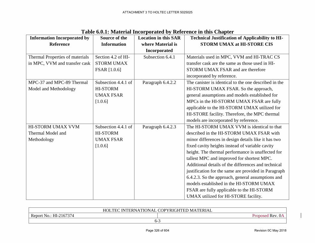
HOLTEC INTERNATIONAL COPYRIGHTED MATERIAL
Report No.: HI-2167374 Proposed Rev. 0A
6-3
Table 6.0.1: Material Incorporated by Reference in this Chapter Information Incorporated by
Reference
Source of the
Information
Location in this SAR
where Material is
Incorporated
Technical Justification of Applicability to HI-
STORM UMAX at HI-STORE CIS
Thermal Properties of materials
in MPC, VVM and transfer cask
Section 4.2 of HI-
STORM UMAX
FSAR [1.0.6]
Subsection 6.4.1 Materials used in MPC, VVM and HI-TRAC CS
transfer cask are the same as those used in HI-
STORM UMAX FSAR and are therefore
incorporated by reference.
MPC-37 and MPC-89 Thermal
Model and Methodology
Subsection 4.4.1 of
HI-STORM
UMAX FSAR
[1.0.6]
Paragraph 6.4.2.2 The canister is identical to the one described in the
HI-STORM UMAX FSAR. So the approach,
general assumptions and models established for
MPCs in the HI-STORM UMAX FSAR are fully
applicable to the HI-STORM UMAX utilized for
HI-STORE facility. Therefore, the MPC thermal
models are incorporated by reference.
HI-STORM UMAX VVM
Thermal Model and
Methodology
Subsection 4.4.1 of
HI-STORM
UMAX FSAR
[1.0.6]
Paragraph 6.4.2.3 The HI-STORM UMAX VVM is identical to that
described in the HI-STORM UMAX FSAR with
minor differences in design details like it has two
fixed cavity heights instead of variable cavity
height. The thermal performance is unaffected for
tallest MPC and improved for shortest MPC.
Additional details of the differences and technical
justification for the same are provided in Paragraph
6.4.2.3. So the approach, general assumptions and
models established in the HI-STORM UMAX
FSAR are fully applicable to the HI-STORM
UMAX utilized for HI-STORE facility.
ATTACHMENT 3 TO HOLTEC LETTER 5025025
Page 326 of 604 Revision 0C May 2018
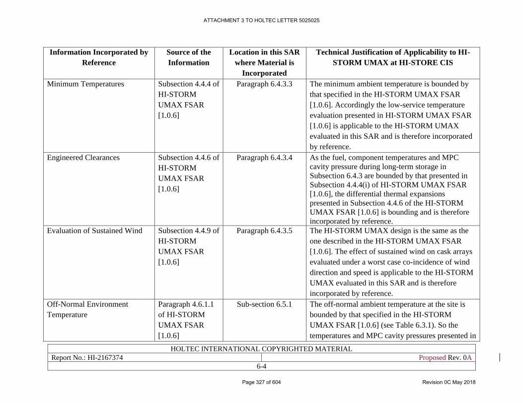
HOLTEC INTERNATIONAL COPYRIGHTED MATERIAL
Report No.: HI-2167374 Proposed Rev. 0A
6-4
Information Incorporated by
Reference
Source of the
Information
Location in this SAR
where Material is
Incorporated
Technical Justification of Applicability to HI-
STORM UMAX at HI-STORE CIS
Minimum Temperatures Subsection 4.4.4 of
HI-STORM
UMAX FSAR
[1.0.6]
Paragraph 6.4.3.3 The minimum ambient temperature is bounded by
that specified in the HI-STORM UMAX FSAR
[1.0.6]. Accordingly the low-service temperature
evaluation presented in HI-STORM UMAX FSAR
[1.0.6] is applicable to the HI-STORM UMAX
evaluated in this SAR and is therefore incorporated
by reference.
Engineered Clearances Subsection 4.4.6 of
HI-STORM
UMAX FSAR
[1.0.6]
Paragraph 6.4.3.4 As the fuel, component temperatures and MPC
cavity pressure during long-term storage in
Subsection 6.4.3 are bounded by that presented in
Subsection 4.4.4(i) of HI-STORM UMAX FSAR
[1.0.6], the differential thermal expansions
presented in Subsection 4.4.6 of the HI-STORM
UMAX FSAR [1.0.6] is bounding and is therefore
incorporated by reference.
Evaluation of Sustained Wind Subsection 4.4.9 of
HI-STORM
UMAX FSAR
[1.0.6]
Paragraph 6.4.3.5 The HI-STORM UMAX design is the same as the
one described in the HI-STORM UMAX FSAR
[1.0.6]. The effect of sustained wind on cask arrays
evaluated under a worst case co-incidence of wind
direction and speed is applicable to the HI-STORM
UMAX evaluated in this SAR and is therefore
incorporated by reference.
Off-Normal Environment
Temperature
Paragraph 4.6.1.1
of HI-STORM
UMAX FSAR
[1.0.6]
Sub-section 6.5.1 The off-normal ambient temperature at the site is
bounded by that specified in the HI-STORM
UMAX FSAR [1.0.6] (see Table 6.3.1). So the
temperatures and MPC cavity pressures presented in
ATTACHMENT 3 TO HOLTEC LETTER 5025025
Page 327 of 604 Revision 0C May 2018
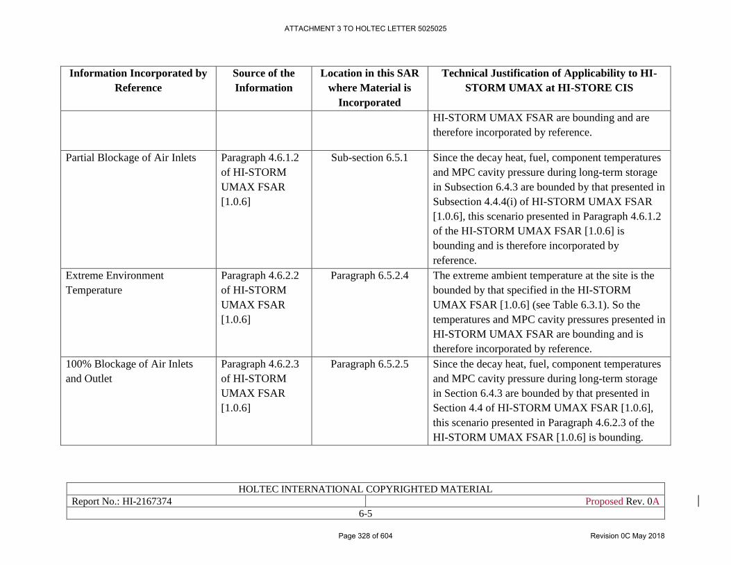
HOLTEC INTERNATIONAL COPYRIGHTED MATERIAL
Report No.: HI-2167374 Proposed Rev. 0A
6-5
Information Incorporated by
Reference
Source of the
Information
Location in this SAR
where Material is
Incorporated
Technical Justification of Applicability to HI-
STORM UMAX at HI-STORE CIS
HI-STORM UMAX FSAR are bounding and are
therefore incorporated by reference.
Partial Blockage of Air Inlets Paragraph 4.6.1.2
of HI-STORM
UMAX FSAR
[1.0.6]
Sub-section 6.5.1 Since the decay heat, fuel, component temperatures
and MPC cavity pressure during long-term storage
in Subsection 6.4.3 are bounded by that presented in
Subsection 4.4.4(i) of HI-STORM UMAX FSAR
[1.0.6], this scenario presented in Paragraph 4.6.1.2
of the HI-STORM UMAX FSAR [1.0.6] is
bounding and is therefore incorporated by
reference.
Extreme Environment
Temperature
Paragraph 4.6.2.2
of HI-STORM
UMAX FSAR
[1.0.6]
Paragraph 6.5.2.4 The extreme ambient temperature at the site is the
bounded by that specified in the HI-STORM
UMAX FSAR [1.0.6] (see Table 6.3.1). So the
temperatures and MPC cavity pressures presented in
HI-STORM UMAX FSAR are bounding and is
therefore incorporated by reference.
100% Blockage of Air Inlets
and Outlet
Paragraph 4.6.2.3
of HI-STORM
UMAX FSAR
[1.0.6]
Paragraph 6.5.2.5 Since the decay heat, fuel, component temperatures
and MPC cavity pressure during long-term storage
in Section 6.4.3 are bounded by that presented in
Section 4.4 of HI-STORM UMAX FSAR [1.0.6],
this scenario presented in Paragraph 4.6.2.3 of the
HI-STORM UMAX FSAR [1.0.6] is bounding.
ATTACHMENT 3 TO HOLTEC LETTER 5025025
Page 328 of 604 Revision 0C May 2018
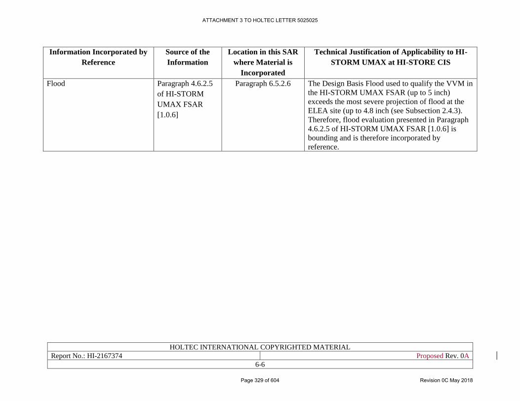
HOLTEC INTERNATIONAL COPYRIGHTED MATERIAL
Report No.: HI-2167374 Proposed Rev. 0A
6-6
Information Incorporated by
Reference
Source of the
Information
Location in this SAR
where Material is
Incorporated
Technical Justification of Applicability to HI-
STORM UMAX at HI-STORE CIS
Flood Paragraph 4.6.2.5
of HI-STORM
UMAX FSAR
[1.0.6]
Paragraph 6.5.2.6 The Design Basis Flood used to qualify the VVM in
the HI-STORM UMAX FSAR (up to 5 inch)
exceeds the most severe projection of flood at the
ELEA site (up to 4.8 inch (see Subsection 2.4.3).
Therefore, flood evaluation presented in Paragraph
4.6.2.5 of HI-STORM UMAX FSAR [1.0.6] is
bounding and is therefore incorporated by
reference.
ATTACHMENT 3 TO HOLTEC LETTER 5025025
Page 329 of 604 Revision 0C May 2018
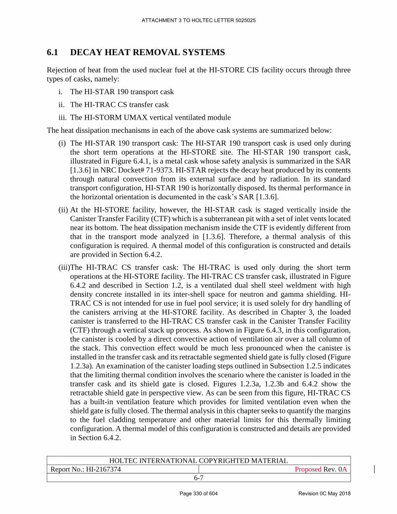
HOLTEC INTERNATIONAL COPYRIGHTED MATERIAL
Report No.: HI-2167374 Proposed Rev. 0A
6-7
6.1 DECAY HEAT REMOVAL SYSTEMS
Rejection of heat from the used nuclear fuel at the HI-STORE CIS facility occurs through three
types of casks, namely:
i. The HI-STAR 190 transport cask
ii. The HI-TRAC CS transfer cask
iii. The HI-STORM UMAX vertical ventilated module
The heat dissipation mechanisms in each of the above cask systems are summarized below:
(i) The HI-STAR 190 transport cask: The HI-STAR 190 transport cask is used only during
the short term operations at the HI-STORE site. The HI-STAR 190 transport cask,
illustrated in Figure 6.4.1, is a metal cask whose safety analysis is summarized in the SAR
[1.3.6] in NRC Docket# 71-9373. HI-STAR rejects the decay heat produced by its contents
through natural convection from its external surface and by radiation. In its standard
transport configuration, HI-STAR 190 is horizontally disposed. Its thermal performance in
the horizontal orientation is documented in the cask’s SAR [1.3.6].
(ii) At the HI-STORE facility, however, the HI-STAR cask is staged vertically inside the
Canister Transfer Facility (CTF) which is a subterranean pit with a set of inlet vents located
near its bottom. The heat dissipation mechanism inside the CTF is evidently different from
that in the transport mode analyzed in [1.3.6]. Therefore, a thermal analysis of this
configuration is required. A thermal model of this configuration is constructed and details
are provided in Section 6.4.2.
(iii)The HI-TRAC CS transfer cask: The HI-TRAC is used only during the short term
operations at the HI-STORE facility. The HI-TRAC CS transfer cask, illustrated in Figure
6.4.2 and described in Section 1.2, is a ventilated dual shell steel weldment with high
density concrete installed in its inter-shell space for neutron and gamma shielding. HI-
TRAC CS is not intended for use in fuel pool service; it is used solely for dry handling of
the canisters arriving at the HI-STORE facility. As described in Chapter 3, the loaded
canister is transferred to the HI-TRAC CS transfer cask in the Canister Transfer Facility
(CTF) through a vertical stack up process. As shown in Figure 6.4.3, in this configuration,
the canister is cooled by a direct convective action of ventilation air over a tall column of
the stack. This convection effect would be much less pronounced when the canister is
installed in the transfer cask and its retractable segmented shield gate is fully closed (Figure
1.2.3a). An examination of the canister loading steps outlined in Subsection 1.2.5 indicates
that the limiting thermal condition involves the scenario where the canister is loaded in the
transfer cask and its shield gate is closed. Figures 1.2.3a, 1.2.3b and 6.4.2 show the
retractable shield gate in perspective view. As can be seen from this figure, HI-TRAC CS
has a built-in ventilation feature which provides for limited ventilation even when the
shield gate is fully closed. The thermal analysis in this chapter seeks to quantify the margins
to the fuel cladding temperature and other material limits for this thermally limiting
configuration. A thermal model of this configuration is constructed and details are provided
in Section 6.4.2.
ATTACHMENT 3 TO HOLTEC LETTER 5025025
Page 330 of 604 Revision 0C May 2018
HOLTEC INTERNATIONAL COPYRIGHTED MATERIAL
Report No.: HI-2167374 Proposed Rev. 0A
6-8
(iv) The HI-STORM UMAX VVMs: The interim storage of the canisters will occur in the HI-
STORM UMAX VVMs. The thermal-hydraulic configuration of the HI-STORM UMAX
VVMs at HI-STORE is essentially identical to that certified in the HI-STORM UMAX
docket. Therefore, its heat rejection capacity would be virtually identical under identical
conditions to that analyzed and certified in [1.0.6] under all operation modes. However, as
can be inferred from Table 6.3.1, the Design Basis heat load and the ambient temperature
metrics for the HI-STORE ISFSI are less challenging than those for which the system is
certified in [1.0.6]. Therefore, it is concluded that the heat rejection performance of the
canisters at the HI-STORE ISFSI will have even greater margins to the regulator-
prescribed limit than that established in [1.0.6]. To ascertain this, long-term storage of
canisters in HI-STORM UMAX with site-specific conditions from Table 6.3.1 is evaluated
in this chapter. A thermal model of the HI-STORM UMAX VVM containing MPC is
constructed and details are provided in Section 6.4.2.
The decay heat removal of HI-STORM UMAX VVMs under normal, off-normal and accident
conditions is evaluated in this chapter. Similarly, thermal performance of HI-TRAC CS transfer
cask and HI-STAR 190 cask under short-term and accident conditions are also evaluated in this
chapter.
ATTACHMENT 3 TO HOLTEC LETTER 5025025
Page 331 of 604 Revision 0C May 2018
HOLTEC INTERNATIONAL COPYRIGHTED MATERIAL
Report No.: HI-2167374 Proposed Rev. 0A
6-9
6.2 MATERIAL TEMPERATURE LIMITS
Material temperature limits are provided in Section 4.4 of Chapter 4. All material considerations
including material degradation modes applicable to HI-STORM UMAX are evaluated in Chapter
17 of this SAR. If the canister arrives at HI-STORE at a date greater than 20 years from the date
of first being placed on a storage pad, the canister is added to the list of canisters undergoing aging
management immediately, a more detailed description of which is provided in Chapter 18 of this
SAR.
ATTACHMENT 3 TO HOLTEC LETTER 5025025
Page 332 of 604 Revision 0C May 2018
HOLTEC INTERNATIONAL COPYRIGHTED MATERIAL
Report No.: HI-2167374 Proposed Rev. 0A
6-10
6.3 THERMAL LOADS AND ENVIRONMENTAL CONDITIONS
The thermal loads and applicable environmental conditions are summarized in Table 6.3.1. This
table also contains the corresponding values for which the HI-STORM UMAX system is certified
in its FSAR [1.0.6]. It can be noted from this table that the site normal, off-normal and accident
ambient temperatures are lower than that adopted on a generic basis in the HI-STORM UMAX
FSAR [1.0.6]. The design basis normal ambient temperature used in this SAR will be exceeded
only for brief periods as suggested by the ambient temperature data in Chapter 2. Inasmuch as the
sole effect of the normal temperature is on the computed fuel cladding temperature to establish
long-term fuel integrity, it should not lie below the time averaged yearly mean for the site.
Previously licensed cask systems have employed yearly averaged normal temperatures (USNRC
Dockets 72-1014, 72-1032 and 72-1040) for evaluation of long-term storage.
ATTACHMENT 3 TO HOLTEC LETTER 5025025
Page 333 of 604 Revision 0C May 2018
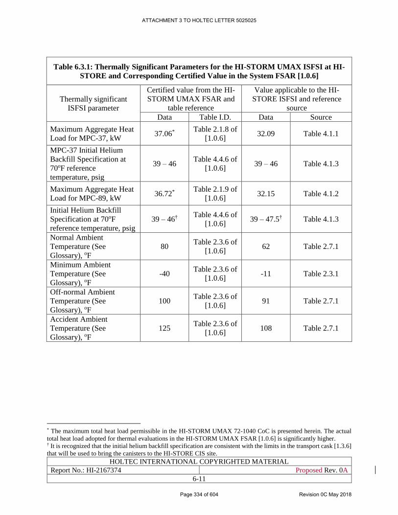
HOLTEC INTERNATIONAL COPYRIGHTED MATERIAL
Report No.: HI-2167374 Proposed Rev. 0A
6-11
Table 6.3.1: Thermally Significant Parameters for the HI-STORM UMAX ISFSI at HI-
STORE and Corresponding Certified Value in the System FSAR [1.0.6]
Thermally significant
ISFSI parameter
Certified value from the HI-
STORM UMAX FSAR and
table reference
Value applicable to the HI-
STORE ISFSI and reference
source
Data Table I.D. Data Source
Maximum Aggregate Heat
Load for MPC-37, kW 37.06*
Table 2.1.8 of
[1.0.6] 32.09 Table 4.1.1
MPC-37 Initial Helium
Backfill Specification at
70oF reference
temperature, psig
39 – 46 Table 4.4.6 of
[1.0.6] 39 – 46 Table 4.1.3
Maximum Aggregate Heat
Load for MPC-89, kW 36.72*
Table 2.1.9 of
[1.0.6] 32.15 Table 4.1.2
Initial Helium Backfill
Specification at 70oF
reference temperature, psig
39 – 46† Table 4.4.6 of
[1.0.6] 39 – 47.5† Table 4.1.3
Normal Ambient
Temperature (See
Glossary), oF
80 Table 2.3.6 of
[1.0.6] 62 Table 2.7.1
Minimum Ambient
Temperature (See
Glossary), oF
-40 Table 2.3.6 of
[1.0.6] -11 Table 2.3.1
Off-normal Ambient
Temperature (See
Glossary), oF
100 Table 2.3.6 of
[1.0.6] 91 Table 2.7.1
Accident Ambient
Temperature (See
Glossary), oF
125 Table 2.3.6 of
[1.0.6] 108 Table 2.7.1
* The maximum total heat load permissible in the HI-STORM UMAX 72-1040 CoC is presented herein. The actual
total heat load adopted for thermal evaluations in the HI-STORM UMAX FSAR [1.0.6] is significantly higher. † It is recognized that the initial helium backfill specification are consistent with the limits in the transport cask [1.3.6]
that will be used to bring the canisters to the HI-STORE CIS site.
ATTACHMENT 3 TO HOLTEC LETTER 5025025
Page 334 of 604 Revision 0C May 2018
HOLTEC INTERNATIONAL COPYRIGHTED MATERIAL
Report No.: HI-2167374 Proposed Rev. 0A
6-12
6.4 APPLICABLE SYSTEMS, ANALYTICAL METHODS, MODELS
AND CALCULATIONS
6.4.1 Applicable Systems
As explained in Subection 1.2.1, HI-STORM UMAX Version C is deployed at HI-STORE CIS.
This design is identical to the design licensed in HI-STORM UMAX docket# 72-1040 except the
following:
• The ultra-high earthquake-resistant options, referred to as MSE options, are not present.
• The storage cavity depth is made fixed (not variable, as permitted in the general
certification) at two discrete dimensions and are referred to as types SL and XL (see
drawing Section 1.5).
As a result of the above, the thermal performance of the system remains either unaffected or
improved depending on the height of the canister being stored. The safety analysis of the HI-
STORM UMAX ISFSI at HI-STORE will be bounded by the generic analysis in the HI-STORM
UMAX docket [1.0.6] since the Design Basis heat load and the ambient temperature metrics for
the HI-STORE ISFSI are less challenging than those for which the system is certified in [1.0.6]
(see Table 6.3.1). To provide further assurance, a thermal evaluation of normal long-term storage
of HI-STORM UMAX Version C VVMs under governing scenario is performed in this section to
demonstrate safety compliance.
Additionally, there are two safety analyses that pertain to short term operations that warrant
quantification of their safety margin. These are:
(i) The HI-STAR 190 transport cask situated in the CTF illustrated in Figure 6.4.1: The HI-
STAR 190 cask is analyzed in its Part 71 docket [1.3.6] wherein its compliance with the
ISG-11 Rev 3 thermal limit under transport is demonstrated. A similar demonstration for
the configuration in Figure 6.4.1 is provided in Subsection 6.4.2.
(ii) HI-TRAC CS transfer cask containing a loaded canister with its shield gates closed: In this
configuration, as shown in Figure 6.4.2, the canister inside the transfer cask has limited
ventilation assistance. In comparison, the configuration wherein the transfer cask is
mounted on top of the HI-STORM UMAX cavity or HI-STAR 190 cavity with its shield
gates wide open (see Figure 6.4.3) has maximum ventilation cooling action and is therefore
ruled out as a governing thermal condition. Thermal model and analysis methodology of
normal onsite transfer in HI-TRAC CS is described in Subsection 6.4.2.
Table 6.4.1 provides the principal input data used in the thermal analysis performed for the above
two short term operation scenarios. Thermal properties of materials used in MPC and VVM storage
system are incorporated by reference from Section 4.2 of HI-STORM UMAX FSAR [1.0.6].
Materials present in HI-TRAC CS transfer cask include steel and concrete, thermal properties of
which are also provided in Section 4.2 of HI-STORM UMAX FSAR [1.0.6]. Similarly properties
of materials used in HI-STAR 190 cask are incorporated by reference from Section 3.3 of HI-
STAR 190 SAR [1.3.6].
ATTACHMENT 3 TO HOLTEC LETTER 5025025
Page 335 of 604 Revision 0C May 2018
HOLTEC INTERNATIONAL COPYRIGHTED MATERIAL
Report No.: HI-2167374 Proposed Rev. 0A
6-13
6.4.2 Analysis Methodology
6.4.2.1 Computer Code
The analysis vehicle for prediction of thermal performance of the systems in this SAR is the
computer code FLUENT [6.4.1]. FLUENT has been benchmarked and validated for use in cask
systems [6.4.2] since 1990s and has been used in the thermal qualification of every storage and
transport cask developed by Holtec since 1995. A summary of pre-qualification benchmarking of
FLUENT is included in Appendix 6.A herein for reference purposes. In Table 6.4.2, a listing of
the licenses or license amendments issued by the USNRC and other regulatory authorities on both
transport and ventilated cask types that utilize FLUENT is summarized. Several cask models listed
in Table 6.4.2 have received numerous licensing amendments over the years. Thus, from this table,
it can be inferred that Holtec’s FLUENT models for simulating ventilated and metal casks have
been repeatedly endorsed by the NRC and other national regulatory authorities.
As in all other HI-STORM dockets, the FLUENT solutions reported in this SAR have been vetted
for numerical stability and grid sensitivity [6.4.3, 6.4.4] (Subsection 4.4.2 of the HI-STORM
UMAX FSAR [1.0.6]).
6.4.2.2 MPC Thermal Model
The thermal analysis model of MPC is incorporated by reference from Section 4.4 of the HI-
STORM UMAX FSAR [1.0.6].
6.4.2.3 HI-STORM UMAX VVM Thermal Model
The HI-STORM UMAX storage VVM used in HI-STORE CIS is slightly modified compared to
the version documented in the HI-STORM UMAX FSAR [1.0.6]. A geometrically accurate 3D
thermal model of the HI-STORM UMAX VVM Version C is constructed in the manner of HI-
STORM UMAX in docket # 72-1040. The scenario of short MPC-37 placed in HI-STORM
UMAX Version C Type SL is thermally governing for the following reasons and is therefore
evaluated in this chapter:
a. As demonstrated in Section 4.4 of HI-STORM UMAX FSAR [1.0.6], thermal evaluations
of MPC-89 are bounded by MPC-37. Since the heat load patterns provided in Section 4.1
of this SAR are bounded by those adopted in the generic HI-STORM UMAX FSAR [1.0.6]
for both MPCs, MPC-37 is the governing canister at HI-STORE also.
b. MPC-37 with short fuel results in highest PCT and component temperatures as
demonstrated in Section 4.4 of HI-STORM UMAX FSAR [1.0.6].
c. Active fuel height of short PWR fuel is lowest among short, reference and long fuel
assemblies. For the same heat load, lower active height results in higher heat load density.
The thermal modeling of the HI-STORM UMAX VVM is incorporated by reference from Section
4.4 of HI-STORM UMAX FSAR [1.0.6]. The quarter symmetric model for the VVM assembly
seeks to represent the essential geometry details of the physical system as depicted in the Licensing
Drawings in Section 1.5 and utilizes the same conservative assumptions as summarized in Section
4.4 of [1.0.6].
Sectional and isometric views of the HI-STORM UMAX VVM quarter symmetric 3D thermal
model are presented in Figures 6.4.4 and 6.4.5 respectively.
ATTACHMENT 3 TO HOLTEC LETTER 5025025
Page 336 of 604 Revision 0C May 2018
HOLTEC INTERNATIONAL COPYRIGHTED MATERIAL
Report No.: HI-2167374 Proposed Rev. 0A
6-14
[
PROPRIETARY INFORMATION WITHHELD IN ACCORDANCE WITH 10CFR2.390
]
6.4.2.4 HI-STAR 190 Thermal Model
To accommodate all PWR and BWR canisters, the HI-STAR 190 cask is available in two discrete
lengths – version SL (standard length) and version XL (extended length), as described in Chapter
1 of HI-STAR 190 SAR [1.3.6]. The HI-STAR 190 Version XL has a larger external surface area
for heat dissipation than that of HI-STAR 190 Version SL. Therefore, the thermal performance of
HI-STAR 190 Version XL is bounded by that of HI-STAR 190 Version SL. The thermal
performance of short MPC-37 bounds that of MPC-89 for similar decay heats as has been
demonstrated in Section 3.3 of HI-STAR 190 SAR [1.3.6], Sections 4.4 of the HI-STORM UMAX
FSAR [1.0.6] and HI-STORM FW FSAR [1.3.7].
Based on the above justification, the shorter version SL with short MPC-37 is thermally most
limiting and is therefore adopted herein. The thermal model of HI-STAR 190 is the same as that
used in its native docket (10CFR71-9373 [1.3.6]). Thermal model of HI-STAR 190 placed inside
the CTF has the following attributes:
[
PROPRIETARY INFORMATION WITHHELD IN ACCORDANCE WITH 10CFR2.390
]
[
ATTACHMENT 3 TO HOLTEC LETTER 5025025
Page 337 of 604 Revision 0C May 2018
HOLTEC INTERNATIONAL COPYRIGHTED MATERIAL
Report No.: HI-2167374 Proposed Rev. 0A
6-15
PROPRIETARY INFORMATION WITHHELD IN ACCORDANCE WITH 10CFR2.390
]
Table 6.4.1 provides the principal input data used in the thermal analysis performed for this short
term operation scenario. Sectional and isometric views of the HI-STAR 190 in CTF quarter
symmetric 3D thermal model are presented in Figures 6.4.6 and 6.4.7 respectively. The
computational results for this scenario are presented in Subsection 6.4.3.
6.4.2.5 HI-TRAC CS Transfer Cask Thermal Model
The HI-TRAC CS is a dry use only cask designed specifically for the HI-STORE CIS facility. HI-
TRAC CS has large cavities to accommodate various heights of MPCs. As described above, short
MPC-37 is the governing thermal scenario and is therefore evaluated to demonstrate safety. Its
thermal model, implemented on FLUENT has the following key attributes:
[
PROPRIETARY INFORMATION WITHHELD IN ACCORDANCE WITH 10CFR2.390
]
ATTACHMENT 3 TO HOLTEC LETTER 5025025
Page 338 of 604 Revision 0C May 2018
HOLTEC INTERNATIONAL COPYRIGHTED MATERIAL
Report No.: HI-2167374 Proposed Rev. 0A
6-16
[
PROPRIETARY INFORMATION WITHHELD IN ACCORDANCE WITH 10CFR2.390
]
Sectional and isometric views of the HI-TRAC quarter symmetric 3D thermal model are presented
in Figures 6.4.8 and 6.4.9 respectively. The computational results for this scenario are presented
in Subsection 6.4.3.
6.4.3 Calculations and Results
6.4.3.1 Maximum Temperatures
A steady state thermal analysis of the governing “thermal configurations” (meaning the
combination of canister type, regionalized loading pattern and fuel type that produces highest fuel
cladding temperature) was performed using the 3-D FLUENT model described in Subsection 6.4.2
to quantify the thermal margins under long term storage conditions. Thermal analyses of the MPC-
37 with short fuel under heat load pattern 1 specified in Table 4.1.1 is performed.
The maximum spatial values of the computed temperatures of the fuel cladding, the fuel basket
material, the divider shell, the closure lid concrete, the MPC lid, the MPC shell and the average
air outlet temperature are summarized in Table 6.4.3. The following conclusions are reached from
the solution data:
a. The PCT is below the temperature limit set forth in ISG-11 Rev 3 [4.0.1].
b. The maximum temperatures of all MPC and VVM constituent parts are below their
respective limits set down in Section 4.4.
c. The temperatures are below the licensed temperatures obtained and presented in Chapter 4
of HI-STORM UMAX FSAR [1.0.6].
ATTACHMENT 3 TO HOLTEC LETTER 5025025
Page 339 of 604 Revision 0C May 2018
HOLTEC INTERNATIONAL COPYRIGHTED MATERIAL
Report No.: HI-2167374 Proposed Rev. 0A
6-17
It is therefore concluded that the HI-STORM UMAX system provides a thermally acceptable
storage environment for the eligible MPCs.
Thermal evaluations in Section 3.3.5 of HI-STAR 190 SAR [1.3.6] demonstrate that the predicted
temperatures and cavity pressures under sub-design basis heat loads* is bounded by those under
design basis maximum heat loads. Therefore, the safety conclusions made for design basis heat
loads also remain applicable to sub-design basis heat loads also.
6.4.3.2 MPC Cavity Pressures
The MPC from HI-STAR 190 is already filled with dry pressurized helium. During normal storage
in HI-STORM UMAX VVM and during short-term operations in HI-TRAC CS and HI-STAR
190, the gas temperature within the MPC rises to its maximum operating basis temperature. The
gas pressure inside the MPC will also increase with rising temperature. The pressure rise is
determined using the ideal gas law. The MPC gas pressure is also subject to substantial pressure
rise under hypothetical rupture of fuel rods.
The MPC maximum gas pressure is computed for a postulated release of fission product gases
from fuel rods into this free space. For these scenarios, the amounts of each of the release gas
constituents in the MPC cavity are summed and the resulting total pressures determined from the
ideal gas law. A concomitant effect of rod ruptures is the increased pressure and molecular weight
of the cavity gases with enhanced rate of heat dissipation by internal helium convection and lower
cavity temperatures. As these effects are substantial under large rod ruptures the 100% rod rupture
accident is conservatively evaluated without credit for increased heat dissipation under increased
pressure and molecular weight of the cavity gases. Based on fission gases release fractions
(NUREG 1567 criteria), rods’ net free volume and initial fill gas pressure, maximum gas pressures
with 1% (normal), 10% (off-normal) and 100% (accident condition) rod rupture are given in Table
6.4.4. The maximum calculated gas pressures reported in Table 6.4.4 are all below the MPC
internal design pressures for normal, off-normal and accident conditions specified in Chapter 4.
6.4.3.3 Minimum Temperatures
The minimum temperature evaluation for HI-STORM UMAX at HI-STORE is bounded by that in
Subsection 4.4.4 of the HI-STORM UMAX FSAR [1.0.6] due to the following:
• The minimum ambient temperature at HI-STORE site is bounded by that defined in HI-
STORM UMAX FSAR [1.0.6] (see Table 6.3.1).
Therefore, Subsection 4.4.4(ii) of the HI-STORM UMAX FSAR [1.0.6] is incorporated by
reference into this document.
6.4.3.4 Engineered Clearances to Eliminate Thermal Interfaces
The differential thermal expansion between MPC and cask components for HI-STORM UMAX
at HI-STORE is bounded by that in Sub-section 4.4.6 of the HI-STORM UMAX FSAR [1.0.6]
due to the following:
* MPC helium initial backfill specification and sub-design basis heat load is defined in Table 4.1.4.
ATTACHMENT 3 TO HOLTEC LETTER 5025025
Page 340 of 604 Revision 0C May 2018
HOLTEC INTERNATIONAL COPYRIGHTED MATERIAL
Report No.: HI-2167374 Proposed Rev. 0A
6-18
The MPC and VVM component temperatures at HI-STORE are lower than that presented for the
same MPC presented in Section 4.4.4(i) of the HI-STORM UMAX FSAR under normal long-term
storage condition [1.0.6].
Therefore, Subsection 4.4.6 of the HI-STORM UMAX FSAR [1.0.6] is incorporated by reference
into this document.
6.4.3.5 Evaluation of Sustained Wind
The effect of sustained wind on HI-STORM UMAX cask arrays at HI-STORE CIS is bounded by
that in Subsection 4.4.9 of the HI-STORM UMAX FSAR [1.0.6] due to the following:
• The MPC and VVM component temperatures at HI-STORE are lower than that presented
for the same MPC presented in Section 4.4.4(i) of the HI-STORM UMAX FSAR under
normal long-term storage condition [1.0.6].
• Wind effects at the site are bounded by those evaluated in Subsection 4.4.9 of the HI-
STORM UMAX FSAR [1.0.6] due to HI-STORM UMAX evaluation under worst case
combination of wind speed and direction.
Therefore, Subsection 4.4.9 of the HI-STORM UMAX FSAR [1.0.6] is incorporated by reference
into this document. The effect of wind presented in Subsection 4.4.9 of the HI-STORM UMAX
FSAR [1.0.6] is dwarfed by the significant margins to temperature limits for the HI-STORM
UMAX at HI-STORE (see Table 6.4.3).
6.4.3.6 Evaluation of HI-STAR 190 in CTF
The calculations performed using the 3-D FLUENT model described in Subsection 6.4.2 provided
steady state results that are summarized in Table 6.4.5. By comparing the results in the above
tables with the acceptable limits in Chapter 4 yield the following conclusions:
i) The peak cladding temperature is considerably below the limit corresponding to short term
operations.
ii) There is a large margin to the limit for the metal temperature of the steel in the cask.
iii) The temperatures of the gamma and neutron blockage materials in the transport cask have
considerable margins to their respective limits.
iv) MPC cavity pressure during this short-term operation is below the design pressure limit
(see Chapter 4).
In summary, the temperatures of all HI-STAR 190 components are well within their prescribed
limits.
6.4.3.7 Evaluation of Normal Onsite Transfer in HI-TRAC CS
The calculations performed using the 3-D FLUENT model described in Subsection 6.4.2 provided
steady state results that are summarized in Table 6.4.6. By comparing the results in the above
tables with the acceptable limits in Chapter 4 yield the following conclusions:
(i) The peak cladding temperature is considerably below the limit corresponding to short term
operations.
ATTACHMENT 3 TO HOLTEC LETTER 5025025
Page 341 of 604 Revision 0C May 2018
HOLTEC INTERNATIONAL COPYRIGHTED MATERIAL
Report No.: HI-2167374 Proposed Rev. 0A
6-19
(ii) There is a large margin to the limit for the metal temperature of the steel in the cask.
(iii)The section average temperature of shielding concrete in HI-TRAC CS is also well within
the permitted limit.
(iv) MPC cavity pressure during this short-term operation is below the design pressure limit
(see Chapter 4).
In summary, the temperatures in every constituent part of HI-TRAC CS are well within their
prescribed regulatory limits.
ATTACHMENT 3 TO HOLTEC LETTER 5025025
Page 342 of 604 Revision 0C May 2018
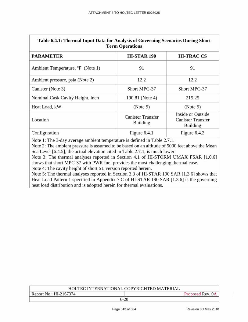
HOLTEC INTERNATIONAL COPYRIGHTED MATERIAL
Report No.: HI-2167374 Proposed Rev. 0A
6-20
Table 6.4.1: Thermal Input Data for Analysis of Governing Scenarios During Short
Term Operations
PARAMETER HI-STAR 190 HI-TRAC CS
Ambient Temperature, oF (Note 1) 91 91
Ambient pressure, psia (Note 2) 12.2 12.2
Canister (Note 3) Short MPC-37 Short MPC-37
Nominal Cask Cavity Height, inch 190.81 (Note 4) 215.25
Heat Load, kW (Note 5) (Note 5)
Location Canister Transfer
Building
Inside or Outside
Canister Transfer
Building
Configuration Figure 6.4.1 Figure 6.4.2
Note 1: The 3-day average ambient temperature is defined in Table 2.7.1.
Note 2: The ambient pressure is assumed to be based on an altitude of 5000 feet above the Mean
Sea Level [6.4.5]; the actual elevation cited in Table 2.7.1, is much lower.
Note 3: The thermal analyses reported in Section 4.1 of HI-STORM UMAX FSAR [1.0.6]
shows that short MPC-37 with PWR fuel provides the most challenging thermal case.
Note 4: The cavity height of short SL version reported herein.
Note 5: The thermal analyses reported in Section 3.3 of HI-STAR 190 SAR [1.3.6] shows that
Heat Load Pattern 1 specified in Appendix 7.C of HI-STAR 190 SAR [1.3.6] is the governing
heat load distribution and is adopted herein for thermal evaluations.
ATTACHMENT 3 TO HOLTEC LETTER 5025025
Page 343 of 604 Revision 0C May 2018
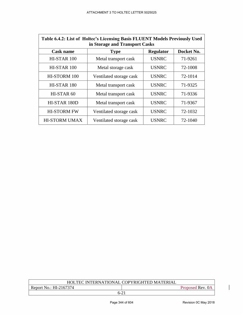
HOLTEC INTERNATIONAL COPYRIGHTED MATERIAL
Report No.: HI-2167374 Proposed Rev. 0A
6-21
Table 6.4.2: List of Holtec’s Licensing Basis FLUENT Models Previously Used
in Storage and Transport Casks
Cask name Type Regulator Docket No.
HI-STAR 100 Metal transport cask USNRC 71-9261
HI-STAR 100 Metal storage cask USNRC 72-1008
HI-STORM 100 Ventilated storage cask USNRC 72-1014
HI-STAR 180 Metal transport cask USNRC 71-9325
HI-STAR 60 Metal transport cask USNRC 71-9336
HI-STAR 180D Metal transport cask USNRC 71-9367
HI-STORM FW Ventilated storage cask USNRC 72-1032
HI-STORM UMAX Ventilated storage cask USNRC 72-1040
ATTACHMENT 3 TO HOLTEC LETTER 5025025
Page 344 of 604 Revision 0C May 2018
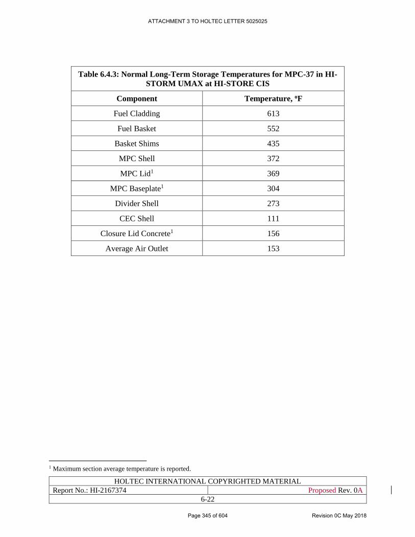
HOLTEC INTERNATIONAL COPYRIGHTED MATERIAL
Report No.: HI-2167374 Proposed Rev. 0A
6-22
Table 6.4.3: Normal Long-Term Storage Temperatures for MPC-37 in HI-
STORM UMAX at HI-STORE CIS
Component Temperature, oF
Fuel Cladding 613
Fuel Basket 552
Basket Shims 435
MPC Shell 372
MPC Lid1 369
MPC Baseplate1 304
Divider Shell 273
CEC Shell 111
Closure Lid Concrete1 156
Average Air Outlet 153
1 Maximum section average temperature is reported.
ATTACHMENT 3 TO HOLTEC LETTER 5025025
Page 345 of 604 Revision 0C May 2018
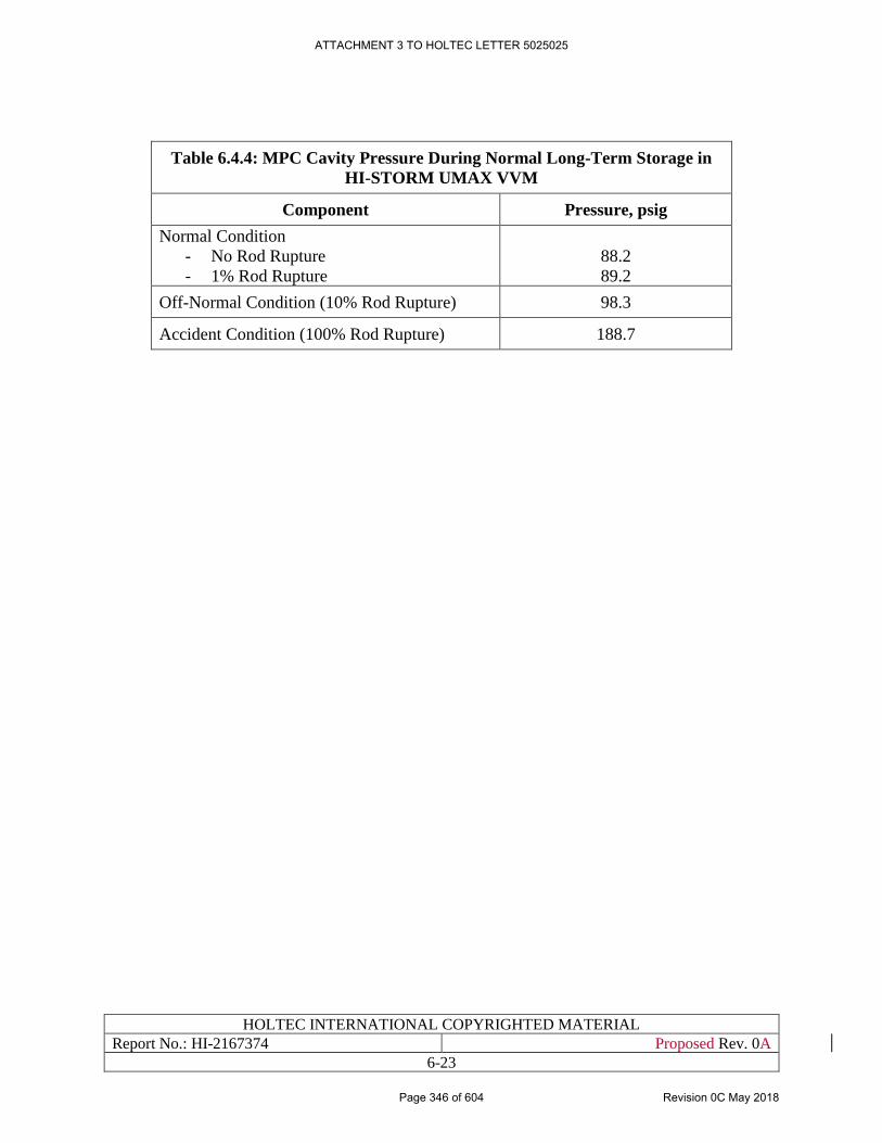
HOLTEC INTERNATIONAL COPYRIGHTED MATERIAL
Report No.: HI-2167374 Proposed Rev. 0A
6-23
Table 6.4.4: MPC Cavity Pressure During Normal Long-Term Storage in
HI-STORM UMAX VVM
Component Pressure, psig
Normal Condition
- No Rod Rupture
- 1% Rod Rupture
88.2
89.2
Off-Normal Condition (10% Rod Rupture) 98.3
Accident Condition (100% Rod Rupture) 188.7
ATTACHMENT 3 TO HOLTEC LETTER 5025025
Page 346 of 604 Revision 0C May 2018
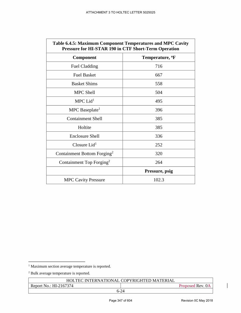
HOLTEC INTERNATIONAL COPYRIGHTED MATERIAL
Report No.: HI-2167374 Proposed Rev. 0A
6-24
Table 6.4.5: Maximum Component Temperatures and MPC Cavity
Pressure for HI-STAR 190 in CTF Short-Term Operation
Component Temperature, oF
Fuel Cladding 716
Fuel Basket 667
Basket Shims 558
MPC Shell 504
MPC Lid1 495
MPC Baseplate1 396
Containment Shell 385
Holtite 385
Enclosure Shell 336
Closure Lid1 252
Containment Bottom Forging2 320
Containment Top Forging2 264
Pressure, psig
MPC Cavity Pressure 102.3
1 Maximum section average temperature is reported.
2 Bulk average temperature is reported.
ATTACHMENT 3 TO HOLTEC LETTER 5025025
Page 347 of 604 Revision 0C May 2018
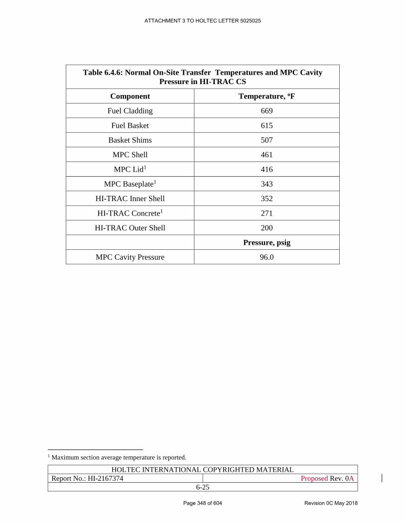
HOLTEC INTERNATIONAL COPYRIGHTED MATERIAL
Report No.: HI-2167374 Proposed Rev. 0A
6-25
Table 6.4.6: Normal On-Site Transfer Temperatures and MPC Cavity
Pressure in HI-TRAC CS
Component Temperature, oF
Fuel Cladding 669
Fuel Basket 615
Basket Shims 507
MPC Shell 461
MPC Lid1 416
MPC Baseplate1 343
HI-TRAC Inner Shell 352
HI-TRAC Concrete1 271
HI-TRAC Outer Shell 200
Pressure, psig
MPC Cavity Pressure 96.0
1 Maximum section average temperature is reported.
ATTACHMENT 3 TO HOLTEC LETTER 5025025
Page 348 of 604 Revision 0C May 2018
HOLTEC INTERNATIONAL COPYRIGHTED MATERIAL
Report No.: HI-2167374 Proposed Rev. 0A
6-26
Figure 6.4.1: [PROPRIETARY INFORMATION WITHHELD IN ACCORDANCE
WITH 10CFR2.390]
ATTACHMENT 3 TO HOLTEC LETTER 5025025
Page 349 of 604 Revision 0C May 2018

HOLTEC INTERNATIONAL COPYRIGHTED MATERIAL
Report No.: HI-2167374 Proposed Rev. 0A
6-27
Figure 6.4.2: [PROPRIETARY INFORMATION WITHHELD IN ACCORDANCE WITH
10CFR2.390]
ATTACHMENT 3 TO HOLTEC LETTER 5025025
Page 350 of 604 Revision 0C May 2018
HOLTEC INTERNATIONAL COPYRIGHTED MATERIAL
Report No.: HI-2167374 Proposed Rev. 0A
6-28
Figure 6.4.3: [PROPRIETARY INFORMATION WITHHELD IN ACCORDANCE WITH
10CFR2.390]
ATTACHMENT 3 TO HOLTEC LETTER 5025025
Page 351 of 604 Revision 0C May 2018

HOLTEC INTERNATIONAL COPYRIGHTED MATERIAL
Report No.: HI-2167374 Proposed Rev. 0A
6-29
Figure 6.4.4: [PROPRIETARY INFORMATION WITHHELD IN ACCORDANCE WITH
10CFR2.390]
ATTACHMENT 3 TO HOLTEC LETTER 5025025
Page 352 of 604 Revision 0C May 2018

HOLTEC INTERNATIONAL COPYRIGHTED MATERIAL
Report No.: HI-2167374 Proposed Rev. 0A
6-30
Figure 6.4.5: [PROPRIETARY INFORMATION WITHHELD IN ACCORDANCE WITH
10CFR2.390]
ATTACHMENT 3 TO HOLTEC LETTER 5025025
Page 353 of 604 Revision 0C May 2018

HOLTEC INTERNATIONAL COPYRIGHTED MATERIAL
Report No.: HI-2167374 Proposed Rev. 0A
6-31
Figure 6.4.6: [PROPRIETARY INFORMATION WITHHELD IN ACCORDANCE WITH
10CFR2.390]
ATTACHMENT 3 TO HOLTEC LETTER 5025025
Page 354 of 604 Revision 0C May 2018
HOLTEC INTERNATIONAL COPYRIGHTED MATERIAL
Report No.: HI-2167374 Proposed Rev. 0A
6-32
Figure 6.4.7: [PROPRIETARY INFORMATION WITHHELD IN ACCORDANCE WITH
10CFR2.390]
ATTACHMENT 3 TO HOLTEC LETTER 5025025
Page 355 of 604 Revision 0C May 2018
HOLTEC INTERNATIONAL COPYRIGHTED MATERIAL
Report No.: HI-2167374 Proposed Rev. 0A
6-33
Figure 6.4.8: [PROPRIETARY INFORMATION WITHHELD IN ACCORDANCE WITH
10CFR2.390]
ATTACHMENT 3 TO HOLTEC LETTER 5025025
Page 356 of 604 Revision 0C May 2018

HOLTEC INTERNATIONAL COPYRIGHTED MATERIAL
Report No.: HI-2167374 Proposed Rev. 0A
6-34
Figure 6.4.9: [PROPRIETARY INFORMATION WITHHELD IN ACCORDANCE WITH
10CFR2.390]
ATTACHMENT 3 TO HOLTEC LETTER 5025025
Page 357 of 604 Revision 0C May 2018
HOLTEC INTERNATIONAL COPYRIGHTED MATERIAL
Report No.: HI-2167374 Proposed Rev. 0A
6-35
6.5 SAFETY UNDER OFF-NORMAL AND ACCIDENT EVENTS
6.5.1 Off-Normal Events
To support evaluation of off-normal events in Section 15.2, the following off-normal events are
evaluated herein:
i) Off-Normal Environment Temperature
ii) Partial Blockage of Air Inlets
iii) Off-Normal Pressure
Thermal evaluations of off-normal events (i) and (ii) are bounded by the evaluations reported in
Sub-section 4.6.1 of the HI-STORM UMAX FSAR [1.0.6] since that the PCT and component
temperatures of MPC stored in HI-STORM UMAX at HI-STORE are lower than that of the same
MPC presented in Section 4.4.4(i) of the HI-STORM UMAX FSAR under normal long-term
storage condition [1.0.6]. Therefore, Subsection 4.6.1 of the HI-STORM UMAX FSAR [1.0.6] is
incorporated by reference into this document.
Thermal evaluation of off-normal event (iii) is presented in Subsection 6.4.3. The off-normal MPC
cavity pressure is below the limit defined in Table 4.3.1 with positive margins.
6.5.2 Accident Events
6.5.2.1 Bounding Fire Event
(a) HI-STORM UMAX Fire Accident: The FSARs of both the HI-STORM UMAX [1.0.6] and the
HI-STORM FW system [1.3.7] contain the fire consequence analysis for a 50 gallon fire at a
generic ISFSI and demonstrate that all of the safety metrics of the storage system will be met.
However, since a transporter with potentially larger volume of combustibles is used on site to
transfer MPCs from HI-TRAC CS transfer cask to HI-STORM UMAX VVM storage module, a
conservative fire event has been considered herein. The amount of combustibles is conservatively
considered equal to that specified in Table 6.5.1. Thermal evaluation of an all engulfing fire of the
aboveground HI-STORM FW System for the same amount of combustibles is presented in a
Holtec report [6.5.3]. The results demonstrate that the fuel and MPC confinement integrity is
assured under this severe fire accident. Based on this, it is safe to conclude that the MPC and its
contents are also safe in HI-STORM UMAX at HI-STORE under transporter fire accident due to
the following:
• The initial PCT and component temperatures of MPC stored in HI-STORM UMAX at HI-
STORE are lower than that of the same MPC in the HI-STORM FW system [6.5.3].
• MPC decay heat is significantly lower in HI-STORM UMAX.
• HI-STORM UMAX system has much lesser surface directly exposed to fire than that of
above-ground system.
Consequently, the conclusion that PCT and components’ temperatures and MPC pressure are
below temperature and pressure limits for transporter fire event drawn in Holtec report [6.5.3]
remain valid for the HI-STORM UMAX system at HI-STORE site.
ATTACHMENT 3 TO HOLTEC LETTER 5025025
Page 358 of 604 Revision 0C May 2018
HOLTEC INTERNATIONAL COPYRIGHTED MATERIAL
Report No.: HI-2167374 Proposed Rev. 0A
6-36
(b) HI-TRAC CS Fire Accident: The case of fire in the Cask Transfer Building (CTB) where the
HI-TRAC CS cask is used to handle the arriving canister, however, is not addressed in the above
referenced FSARs. While the probability of a fire event in the CTB is quite low due to the lack of
combustible materials, except the fuel in the Vertical Cask Transporter’s tank (procedurally limited
to 50 gallons), a conservative fire event has been assumed herein and analyzed. Under a postulated
fuel tank fire, the outer layers of HI-TRAC CS cask will be heated for the duration of fire by the
incident thermal radiation and forced convection heat fluxes.
To make the fire event even more severe, the quantity of combustible fluid in the VCT has been
conservatively increased to as adopted in Table 6.5.1. The fuel tank fire is conservatively assumed
to surround the HI-TRAC CS cask thus exposing the entire external to heating by radiation and
convection heat transfer. Following the 10 CFR 71 guidelines [1.3.2], the following fire parameters
are assumed:
[
PROPRIETARY INFORMATION WITHHELD IN ACCORDANCE WITH
10CFR2.390
]
ATTACHMENT 3 TO HOLTEC LETTER 5025025
Page 359 of 604 Revision 0C May 2018
HOLTEC INTERNATIONAL COPYRIGHTED MATERIAL
Report No.: HI-2167374 Proposed Rev. 0A
6-37
[
PROPRIETARY INFORMATION WITHHELD IN ACCORDANCE WITH
10CFR2.390
]
ATTACHMENT 3 TO HOLTEC LETTER 5025025
Page 360 of 604 Revision 0C May 2018
HOLTEC INTERNATIONAL COPYRIGHTED MATERIAL
Report No.: HI-2167374 Proposed Rev. 0A
6-38
The results of the fire and post-fire events are reported in Table 6.5.2. These results demonstrate
the following:
• The fire event has a minor effect on the fuel cladding temperature. The peak cladding
temperature remains below the applicable ISG-11 Rev 3 [4.0.1] limit.
• The internal pressure in the canister remains below its accident condition limit.
• Localized regions of shielding concrete in the body of HI-TRAC CS up to less than 0.25
inch depth are exposed to temperatures in excess of accident temperature limit set forth in
Chapter 4, Table 4.4.1. The bulk of the concrete remains well below the accident
temperature limit.
• The metal temperature of the steel weldment of the HI-TRAC CS cask is also well within
the applicable limit in Table 4.4.1.
It is thus concluded that the suitability of the HI-TRAC CS cask to render its canister transfer
function will remain essentially unimpaired after the bounding fire event postulated in the
foregoing.
(c) HI-STAR 190 Fire Accident: All loading/lifting operations related to HI-STAR 190 transport
cask after arriving at the facility is performed using CTB crane (see Section 10.3). The CTB crane
does not have sources of combustibles to cause a potential fire hazard. The HI-TRAC CS transfer
cask is also operated using the crane and placed on the CTF alignment plate for MPC transfer from
HI-STAR 190 to HI-TRAC CS. The transporter is only used for transfer operations with HI-TRAC
CS, which is always distant from the CTF or HI-STAR 190 cask. Any potential hazard from
transporter fire is bounded by the 30 minute fire evaluation in Section 3.4 of the HI-STAR 190
SAR [1.3.6] and is therefore incorporated by reference.
(d) Potential Fire Hazards: Site survey in Subsection 2.1.2 yields potential hazards which are
evaluated herein. These are the presence of an oil recovery facility and underground run natural
gas pipelines at the facility. There are no active oil wells on the site and there are no plans to use
any of the plugged and abandoned wells on site. This section reviews the potential fire hazards
from these sources that could affect spent fuel storage operations at storage pad and/or cask transfer
operations along the haul path. The identified hazards from oil well and natural gas pipelines are
evaluated for credibility and severity.
As stated in Table 2.1.4, the oil recovery facility or oil well is at a substantial distance from any
cask structure either on the storage pad or haul path to cause a significant impact on fuel cladding
temperature or cask structures. In an unlikely event oil well catches fire, emergency response plans
are in place to mitigate the fire. If the oil well catches fire during transfer of MPC in HI-TRAC CS
on the haul path, transfer cask shall be moved either to the storage pad or the cask transfer building.
The temporary flexible pipelines that run aboveground through the center of the site will be moved
prior to or during the early construction phases of the CIS facility, as described in Subsection 2.1.2.
Therefore, they do not present a fire hazard. The natural gas pipelines that run underground along
the north-south axis to the east of the site do not present a real fire hazard.
(e) Range-Land Fires and Fire-Jump Hazards: Rangeland fires do not pose a credible threat to
the safety of spent nuclear fuel stored at the HI-STORE CIS facility as justified below:
ATTACHMENT 3 TO HOLTEC LETTER 5025025
Page 361 of 604 Revision 0C May 2018
HOLTEC INTERNATIONAL COPYRIGHTED MATERIAL
Report No.: HI-2167374 Proposed Rev. 0A
6-39
- Fuel stored in an underground cavity having no line of sight for radiation heating.
- The HI-STORE CIS facility is designed and operated as a vegetation-free storage area
within the controlled area boundary.
- The ISFSI layout includes a substantial distance (over 500 ft) from the storage pads to
the controlled area boundary.
- Site includes suitable width (approx. 3 dozer widths) of vegetation cleared land
around the controlled area boundary.
- Due to large distances separating potential vegetation fires and UMAX storage
modules fire heating reasonably bounded by design basis fire accidents evaluated
herein as all-engulfing fires.
- As evaluated above the HI-STORE CIS designed as a vegetation free facility renders
fire-jump hazards non-credible.
6.5.2.2 Explosion Event
There are no credible internal explosive events at the HI-STORE ISFSI since all materials are
compatible with the various operating environments, as discussed in Chapter 17, or appropriate
preventive measures are taken to preclude internal explosive events (see Table 4.3.1). The canister
is composed of non-explosive materials and maintains an inert gas environment. Thus explosion
during long term storage is not credible. Likewise, the mandatory use of the protective measures
at the HI-STORE site to prevent fires and explosions and the absence of any need for an explosive
material during loading and unloading operations eliminates the scenario of an explosion as a
credible event. Furthermore, because the MPC is internally pressurized, any short-term external
pressure from explosion will act to reduce the tensile state of stress in the enclosure vessel.
Nevertheless, a design basis external pressure (Table 4.3.1) has been defined as a design basis
loading event wherein the internal pressure is non-mechanistically assumed to be absent. The
ability of the canister to withstand loads due to an explosion event is evaluated in Chapter 3 of HI-
STORM FW FSAR [1.3.7].
6.5.2.3 Burial under Debris
(a) Burial of HI-STORM UMAX VVM
There are no structures that loom over the HI-STORE HI-STORM UMAX ISFSI whose collapse
could bury the VVMs in debris. A substantial distance from the ISFSI to the nearest ISFSI security
fence (see Drawing in Section 1.5) precludes the close proximity of substantial amount of
vegetation (native vegetation is low lying scrub). Thus, there is no credible mechanism for the HI-
STORM UMAX system to become completely buried under debris.
(b) Collapse of the CTB
The CTB is a non-load bearing Butler building made of corrugated aluminum. The building does
not support any crane or other loads and is designed to withstand the maximum wind applicable
to the HI-STORE site. It is nevertheless assumed that the roof of the CTB will fall and cover the
canister bearing casks that are in use within the CTB. The governing burial scenarios are shown in
Figures 6.4.1 and 6.4.2 that involve the HI-STAR 190 metal cask (unventilated) and the HI-TRAC
CS cask (ventilated), respectively. Because of the corrugated shape of the debris and the physical
ATTACHMENT 3 TO HOLTEC LETTER 5025025
Page 362 of 604 Revision 0C May 2018
HOLTEC INTERNATIONAL COPYRIGHTED MATERIAL
Report No.: HI-2167374 Proposed Rev. 0A
6-40
restrictions, it is assumed that the debris restricts the exiting air flow to only 10% of the
unobstructed (normal) condition. A FLUENT analysis of the restricted flow in Figures 6.4.1 and
6.4.2 is performed. The steady state results for this accident on HI-TRAC CS and HI-STAR 190
when it is in the CTF are summarized in Tables 6.5.3 and 6.5.4. The results demonstrate integrity
on fuel cladding and MPC confinement boundary are assured under a postulated CTB collapse
accident.
6.5.2.4 Extreme Environmental Temperature
The extreme environmental accident evaluation for HI-STORM UMAX at HI-STORE is bounded
by that in Paragraph 4.6.2.2 of the HI-STORM UMAX FSAR [1.0.6] due to the following:
• The PCT and component temperatures of MPC stored in HI-STORM UMAX at HI-
STORE are lower than that of the same MPC presented in Section 4.4.4(i) of the HI-
STORM UMAX FSAR under normal long-term storage condition [1.0.6].
• The extreme environment temperature at HI-STORE site is lower than that defined in HI-
STORM UMAX FSAR [1.0.6] (see Table 6.3.1).
Therefore, Paragraph 4.6.2.2 of the HI-STORM UMAX FSAR [1.0.6] is incorporated by reference
into this document.
6.5.2.5 100% Blockage of Air Vents
Thermal evaluation of 100% blockage of air vents accident event is bounded by that in Paragraph
4.6.2.3 of the HI-STORM UMAX FSAR [1.0.6] due to the following:
• The initial condition of the PCT and component temperatures of MPC stored in HI-
STORM UMAX at HI-STORE is lower than that of the same MPC presented in Section
4.4.4(i) of the HI-STORM UMAX FSAR under normal long-term storage condition
[1.0.6].
• Design basis heat load is lower in HI-STORM UMAX at HI-STORE (see Table 6.3.1)
which results in lower heat-up rate.
Therefore, Paragraph 4.6.2.3 of the HI-STORM UMAX FSAR [1.0.6] is incorporated by reference
into this document. The amount of heat removed from the MPC external surfaces by natural
circulation of air is reduced to less than 1% of that under normal conditions (i.e. when inlet and
outlet vents completely unblocked). Therefore, in an event of complete blockage of both inlet and
outlet vents, that small additional heat removal capability by air through outlet vents is also lost.
This will result in a small temperature rise compared to the large available temperature margins
established from the transient study of complete inlet vents blockage in Paragraph 4.6.2.3 of the
HI-STORM UMAX FSAR [1.0.6]. This accident condition is, however, a short duration event that
is identified and corrected through scheduled periodic surveillance. The periodic surveillance time
requirement is adopted the same as that in HI-STORM UMAX FSAR [1.0.6].
6.5.2.6 Flood
The flood accident evaluation is bounded by that in Paragraph 4.6.2.5 of the HI-STORM UMAX
FSAR [1.0.6] due to the following:
ATTACHMENT 3 TO HOLTEC LETTER 5025025
Page 363 of 604 Revision 0C May 2018
HOLTEC INTERNATIONAL COPYRIGHTED MATERIAL
Report No.: HI-2167374 Proposed Rev. 0A
6-41
• The Design Basis Flood used to qualify the VVM in the HI-STORM UMAX FSAR [1.0.6]
(up to 5 inch) exceeds the most severe projection of flood at the ELEA site i.e. up to 4.8
inch (see Subsection 2.4.3).
• The initial condition of the PCT and component temperatures of MPC stored in HI-
STORM UMAX at HI-STORE is lower than that of the same MPC presented in Section
4.4.4(i) of the HI-STORM UMAX FSAR under normal long-term storage condition
[1.0.6].
Therefore, Paragraph 4.6.2.5 of the HI-STORM UMAX FSAR [1.0.6] is incorporated by reference
into this document.
6.5.3 SSCs Important to Safety Guidance for Fire Protection Program
There are no combustible or explosive materials associated with the HI-STORM UMAX System.
Combustible materials will not be stored within an ISFSI. However, for conservatism, a
hypothetical fire accident has been analyzed as a bounding condition for HI-STORM UMAX
System. The evaluation of the HI-STORM UMAX System fire accident is discussed in Subsection
6.5.2. Similarly, there are no credible internal explosive events at the HI-STORE ISFSI since all
materials are compatible with the operating environments, or appropriate preventive measures are
taken to preclude explosions. The canister is composed of non-explosive materials and maintains
an inert gas environment. Thus explosion during long term storage is not credible. Likewise, the
mandatory use of the protective measures at the HI-STORE site to prevent fires and explosions
and the absence of any need for an explosive material during loading and unloading operations
eliminates the scenario of an explosion as a credible event. An emergency response plan is in place
as described in emergency response plan report [10.5.1]. The Holtec CISF Emergency Response
Plan [10.5.1] evaluates and describes the necessary and sufficient emergency response capabilities
for managing fire emergency conditions associated with the operation of the HI-STORE facility.
The plan meets all requirements of 10CFR72.32 (a).
Measures for fire prevention, fire detection, fire suppression, and fire containment for the
protection of the spent fuel assemblies and cask structures important to safety are provided in
emergency response plan [10.5.1]. The fire detection and suppression systems are contained within
the Canister Transfer Building. The construction materials of the Canister Transfer Building do
not support combustion, and the fire-prone materials are limited to diesel fuel. Fires are analyzed
for all casks in Subsection 6.5.2 of this SAR. The area surrounding the storage pads and Canister
Transfer Building includes a gravel-covered fire break with vegetation control to limit potential
fuel for fires. The nonflammable nature of the materials of construction, other passive design
features, and the limited fuel sources at the Facility lead to the conclusion that the fire detection
and suppression systems are correctly classified as not important to safety.
The design of the Facility is such that all structures, systems, and components are located within a
region covered with crushed rock. Therefore, there is no credible wildfire load on structures,
systems, and components important to safety. A range of onsite fire scenarios has been evaluated.
Bounding fire events are based on the volume of combustibles in the transporter, as given in Table
6.5.1. Operational restrictions are in place to ensure that these levels are not exceeded. The cask
structures are designed so that they can continue to perform their safety functions under credible
ATTACHMENT 3 TO HOLTEC LETTER 5025025
Page 364 of 604 Revision 0C May 2018
HOLTEC INTERNATIONAL COPYRIGHTED MATERIAL
Report No.: HI-2167374 Proposed Rev. 0A
6-42
fire and explosion exposure conditions. Additionally, the cask structures containing spent fuel are
located at significant distances from potential fire hazards identified on site.
ATTACHMENT 3 TO HOLTEC LETTER 5025025
Page 365 of 604 Revision 0C May 2018
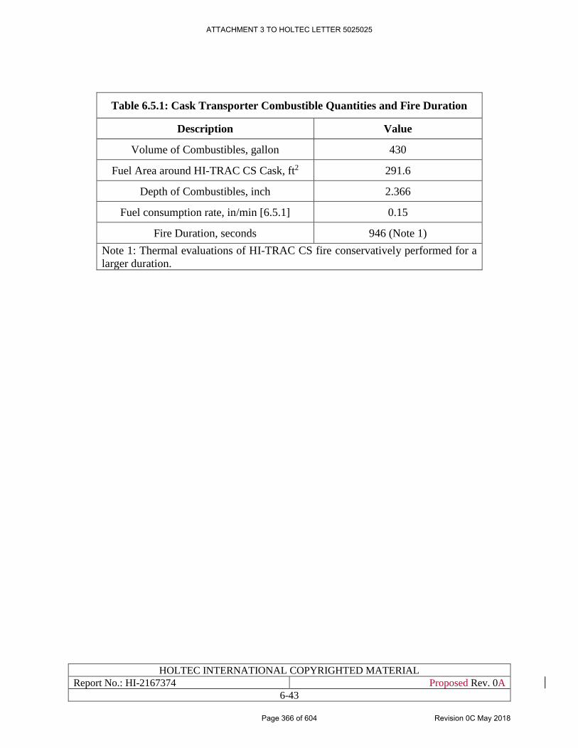
HOLTEC INTERNATIONAL COPYRIGHTED MATERIAL
Report No.: HI-2167374 Proposed Rev. 0A
6-43
Table 6.5.1: Cask Transporter Combustible Quantities and Fire Duration
Description Value
Volume of Combustibles, gallon 430
Fuel Area around HI-TRAC CS Cask, ft2 291.6
Depth of Combustibles, inch 2.366
Fuel consumption rate, in/min [6.5.1] 0.15
Fire Duration, seconds 946 (Note 1)
Note 1: Thermal evaluations of HI-TRAC CS fire conservatively performed for a
larger duration.
ATTACHMENT 3 TO HOLTEC LETTER 5025025
Page 366 of 604 Revision 0C May 2018
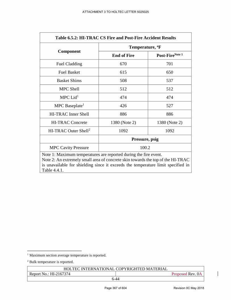
HOLTEC INTERNATIONAL COPYRIGHTED MATERIAL
Report No.: HI-2167374 Proposed Rev. 0A
6-44
Table 6.5.2: HI-TRAC CS Fire and Post-Fire Accident Results
Component Temperature, oF
End of Fire Post-FireNote 1
Fuel Cladding 670 701
Fuel Basket 615 650
Basket Shims 508 537
MPC Shell 512 512
MPC Lid1 474 474
MPC Baseplate1 426 527
HI-TRAC Inner Shell 886 886
HI-TRAC Concrete 1380 (Note 2) 1380 (Note 2)
HI-TRAC Outer Shell2 1092 1092
Pressure, psig
MPC Cavity Pressure 100.2
Note 1: Maximum temperatures are reported during the fire event.
Note 2: An extremely small area of concrete skin towards the top of the HI-TRAC
is unavailable for shielding since it exceeds the temperature limit specified in
Table 4.4.1.
1 Maximum section average temperature is reported.
2 Bulk temperature is reported.
ATTACHMENT 3 TO HOLTEC LETTER 5025025
Page 367 of 604 Revision 0C May 2018
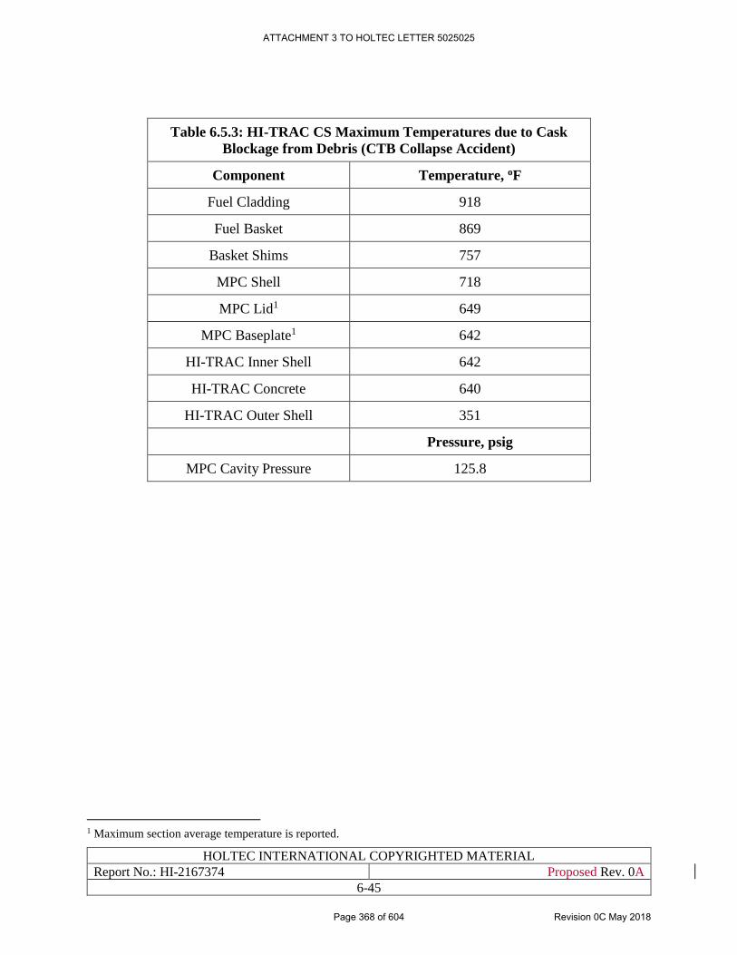
HOLTEC INTERNATIONAL COPYRIGHTED MATERIAL
Report No.: HI-2167374 Proposed Rev. 0A
6-45
Table 6.5.3: HI-TRAC CS Maximum Temperatures due to Cask
Blockage from Debris (CTB Collapse Accident)
Component Temperature, oF
Fuel Cladding 918
Fuel Basket 869
Basket Shims 757
MPC Shell 718
MPC Lid1 649
MPC Baseplate1 642
HI-TRAC Inner Shell 642
HI-TRAC Concrete 640
HI-TRAC Outer Shell 351
Pressure, psig
MPC Cavity Pressure 125.8
1 Maximum section average temperature is reported.
ATTACHMENT 3 TO HOLTEC LETTER 5025025
Page 368 of 604 Revision 0C May 2018
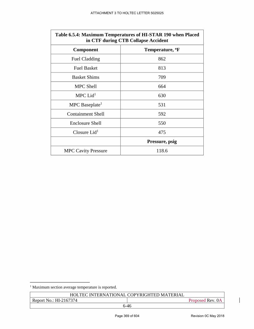
HOLTEC INTERNATIONAL COPYRIGHTED MATERIAL
Report No.: HI-2167374 Proposed Rev. 0A
6-46
Table 6.5.4: Maximum Temperatures of HI-STAR 190 when Placed
in CTF during CTB Collapse Accident
Component Temperature, oF
Fuel Cladding 862
Fuel Basket 813
Basket Shims 709
MPC Shell 664
MPC Lid1 630
MPC Baseplate1 531
Containment Shell 592
Enclosure Shell 550
Closure Lid1 475
Pressure, psig
MPC Cavity Pressure 118.6
1 Maximum section average temperature is reported.
ATTACHMENT 3 TO HOLTEC LETTER 5025025
Page 369 of 604 Revision 0C May 2018
HOLTEC INTERNATIONAL COPYRIGHTED MATERIAL
Report No.: HI-2167374 Proposed Rev. 0A
6-47
6.6 REGULATORY COMPLIANCE
The thermal compliance pursuant to the provisions of NUREG-1567 [1/0/3] and ISG-11 [4.0.1]
for deployment of canisters certified in the HI-STORM UMAX docket number (72-1040) has been
demonstrated in this chapter. As the canisters will arrive at the HI-STORE site loaded in the
transport package, the Short Term Operations on the (dry) canisters to place them in the HI-
STORM UMAX VVMs and their interim storage in the VVMs are the subjects of safety analysis
in this chapter.
Following the guidance of ISG-11 [4.0.1], the fuel cladding temperature at the beginning of dry
storage at HI-STORE will be below the anticipated damage-threshold temperatures for normal
conditions of storage for the licensed life of the HI-STORM UMAX System. Maximum fuel
cladding temperatures for long-term storage conditions are reported in Section 6.4. The large
margin to the ISG-11 limit for the fuel cladding temperature at the HI-STORE ISFSI provides
added assurance that the breach of fuel cladding in storage is extremely unlikely.
Following the guidance of NUREG-1567, the system is passively cooled. All heat rejection
mechanisms described in this chapter, including conduction, natural convection, and thermal
radiation, are completely passive.
During Short Term Operations, the ISG-11 requirement to ensure that maximum cladding
temperatures be below 400oC (752oF) for high burnup fuel and below 570oC (1058oF) for moderate
burnup fuel is satisfied with ample margin.
Events of extremely low probability such as an enveloping fire and an extreme environmental
phenomenon leading to burial of the transfer or transport cask in debris have been analyzed for
their compliance with the temperature limits set down for fuel cladding, structural weldments and
shielding materials. The results show ample margins of safety against regulatory limits.
It is therefore concluded that all applicable regulatory requirements and guidelines germane to the
integrity of the stored fuel and the HI-STORM UMAX storage system have been addressed and
satisfied in this chapter.
ATTACHMENT 3 TO HOLTEC LETTER 5025025
Page 370 of 604 Revision 0C May 2018
HOLTEC INTERNATIONAL COPYRIGHTED MATERIAL
Report No.: HI-2167374 Proposed Rev. 0A
6.A-1
APPENDIX 6A: [PROPRIETARY APPENDIX WITHHELD IN
ITS ENTIRETY IN ACCORDANCE WITH 10CFR2.390]
ATTACHMENT 3 TO HOLTEC LETTER 5025025
Page 371 of 604 Revision 0C May 2018
HOLTEC INTERNATIONAL COPYRIGHTED MATERIAL
Report No.: HI-2167374 Proposed Rev. 0A
7-1
CHAPTER 7: SHIELDING EVALUATION
7.0 INTRODUCTION
The shielding evaluations for the HI-STORE CIS Facility are presented in this chapter, including
dose and dose rate calculations to show that the facility is in compliance with the applicable
regulatory requirements.
Specifically, evaluations and calculations are presented here for the following conditions and
configurations:
• Owner Controlled Area boundary, with dose rates and annual dose for the location closest
to the ISFSI. An ISFSI with 500 loaded HI-STORM UMAX VVMs, consistent with the
description in Section 1.1, is used for the evaluations, and conservative assumptions on the
content of each canister.
• Occupational dose rates at the surface and 1 meter from a single HI-STORM UMAX.
• Occupational dose rates at the surface, 0.5 meters, 1 meter, and 2 meters from the HI-TRAC
CS
The HI-STORE CIS Facility utilizes the HI-STORM UMAX storage system (Docket #72-1040),
and only canisters approved for that system and listed in Table 1.0.3 are permitted for storage in
the facility. Therefore, the principal calculational approach, including principal assumptions and
methodologies, are directly taken from the HI-STORM UMAX FSAR, and are incorporated by
reference. Table 7.0.1 lists all sections from the HI-STORM UMAX FSAR that are incorporated
by reference, together with a technical justification. However, some additional shielding
evaluation that is different from that in the HI-STORM UMAX FSAR is required specifically for
the HI-STORE CIS Facility, due to site-specific considerations. These additional shielding
evaluations are clearly identified in the following sections. In brief, they contain the following:
• The dose analyses in the HI-STORM UMAX FSAR focus on dose rates around a single
VVM, and only a few hypothetical ISFSI configurations were analyzed. In the evaluations
presented here, the full ISFSI as described in Section 1.1 is used as the basis of the
evaluation.
• The HI-STORM UMAX storage VVM used here is slightly modified compared to the
version documents in the HI-STORM UMAX FSAR [1.0.6], with lower doses and other
improvements not related to the shielding analyses. General details of this version are
presented in Section 1.2. This is considered in the dose evaluations presented here.
• The HI-STORM UMAX FSAR assumes the use of a generic transfer cask (HI-TRAC VW)
suitable for canister loading in a spent fuel pool. Since wet loading of canisters is not part
of the operation of the HI-STORE CIS facility, a different HI-TRAC, termed HI-TRAC
CS, with improved shielding and improved operational characteristics is used. Details of
All references are in placed within square brackets in this report and are compiled in Chapter
19 (References)
ATTACHMENT 3 TO HOLTEC LETTER 5025025
Page 372 of 604 Revision 0C May 2018
HOLTEC INTERNATIONAL COPYRIGHTED MATERIAL
Report No.: HI-2167374 Proposed Rev. 0A
7-2
this HI-TRAC CS are presented in Section 1.2. Dose rate evaluations for this transfer cask
are presented in this chapter.
• The dose estimates for loading operations consider the operational sequence for canister
loading at the HI-STORE facility, which includes the unloading of the transport cask,
stackup operation between the transport cask and the HI-TRAC CS, transfer movement to
the HI-STORM UMAX VVM ISFSI, and downloading of the canister into the HI-STORM
UMAX VVM.
ATTACHMENT 3 TO HOLTEC LETTER 5025025
Page 373 of 604 Revision 0C May 2018
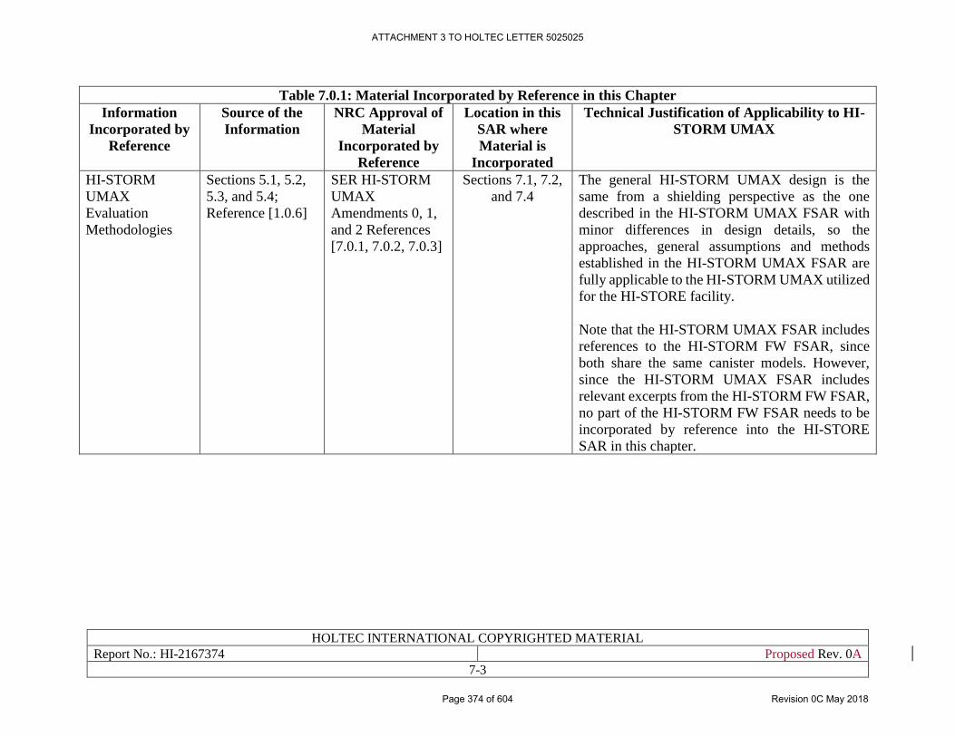
HOLTEC INTERNATIONAL COPYRIGHTED MATERIAL
Report No.: HI-2167374 Proposed Rev. 0A
7-3
Table 7.0.1: Material Incorporated by Reference in this Chapter
Information
Incorporated by
Reference
Source of the
Information
NRC Approval of
Material
Incorporated by
Reference
Location in this
SAR where
Material is
Incorporated
Technical Justification of Applicability to HI-
STORM UMAX
HI-STORM
UMAX
Evaluation
Methodologies
Sections 5.1, 5.2,
5.3, and 5.4;
Reference [1.0.6]
SER HI-STORM
UMAX
Amendments 0, 1,
and 2 References
[7.0.1, 7.0.2, 7.0.3]
Sections 7.1, 7.2,
and 7.4
The general HI-STORM UMAX design is the
same from a shielding perspective as the one
described in the HI-STORM UMAX FSAR with
minor differences in design details, so the
approaches, general assumptions and methods
established in the HI-STORM UMAX FSAR are
fully applicable to the HI-STORM UMAX utilized
for the HI-STORE facility.
Note that the HI-STORM UMAX FSAR includes
references to the HI-STORM FW FSAR, since
both share the same canister models. However,
since the HI-STORM UMAX FSAR includes
relevant excerpts from the HI-STORM FW FSAR,
no part of the HI-STORM FW FSAR needs to be
incorporated by reference into the HI-STORE
SAR in this chapter.
ATTACHMENT 3 TO HOLTEC LETTER 5025025
Page 374 of 604 Revision 0C May 2018
HOLTEC INTERNATIONAL COPYRIGHTED MATERIAL
Report No.: HI-2167374 Proposed Rev. 0A
7-4
7.1 CONTAINED RADIATION SOURCES
7.1.1 General Specification and Approach for Neutron and Gamma Sources
The HI-STORE CIS Facility is designed for spent fuel and associated hardware in sealed canisters.
The principal description of the source terms for the fuel, together with the calculations
methodologies, is presented in Section 5.2 of the HI-STORM UMAX FSAR [1.0.6], which is
incorporated here by reference. The only additional discussion needed here is the justification of
the design basis assembly assumption presented below.
7.1.2 Design Basis Assemblies
The design basis assemblies in [1.0.6] are industry standard 17x17 PWR assemblies, with a
burnup, enrichment and cooling time combination specified in Table 5.0.1 of [1.0.6]. These
parameters while conservative for HI-STORM UMAX systems loaded on ISFSIs at Nuclear Power
Plant sites, far exceed the allowable heat load of the HI-STAR 190 (Table 7.C.7 of Reference
[1.3.6]) and other transportation casks that would be used to transport canisters to the HI-STORE
CIS Facility. Therefore, a conservative but more realistic set of burnup, cooling time, and initial
enrichment parameters as shown in Table 7.1.1 that have a heat load comparable to Table 4.1.1
are used for site-specific HI-STORE CIS Facility shielding calculations.
A number of conservative assumptions are applied throughout the HI-STORE CIS Facility
shielding calculations. These assumptions assure that actual dose rates will always be below the
calculated dose rates, and below regulatory limits. Selected key assumptions are:
[
PROPRIETARY INFORMATION WITHHELD PER 10CFR2.390
]
ATTACHMENT 3 TO HOLTEC LETTER 5025025
Page 375 of 604 Revision 0C May 2018
HOLTEC INTERNATIONAL COPYRIGHTED MATERIAL
Report No.: HI-2167374 Proposed Rev. 0A
7-5
• Assemblies with higher burnups
o Those would also have correspondingly higher cooling times to meet transport
requirements
• PWR fuel assemblies that differ from HI-STORM UMAX FSAR [1.0.6] design basis fuel
assemblies
• The MPC-89 canister with BWR fuel.
o Calculations for the HI-STORM FW [1.3.7] show that the results for the MPC-37
and MPC-89 are comparable
ATTACHMENT 3 TO HOLTEC LETTER 5025025
Page 376 of 604 Revision 0C May 2018
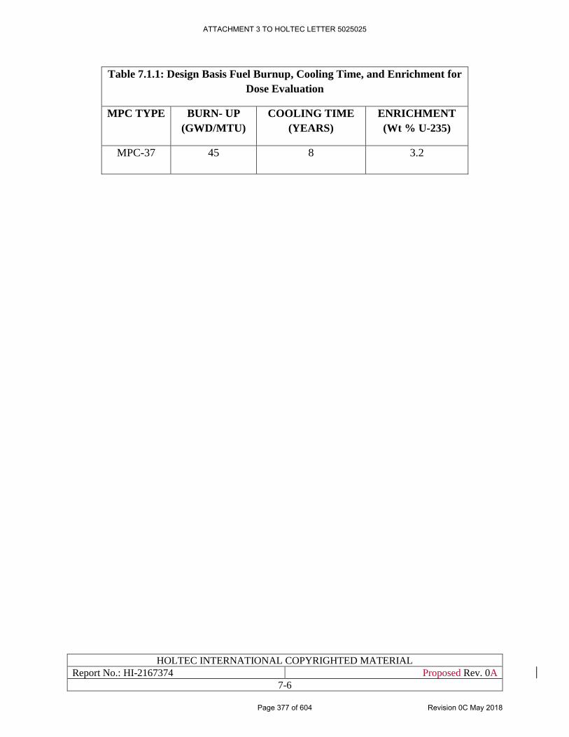
HOLTEC INTERNATIONAL COPYRIGHTED MATERIAL
Report No.: HI-2167374 Proposed Rev. 0A
7-6
Table 7.1.1: Design Basis Fuel Burnup, Cooling Time, and Enrichment for
Dose Evaluation
MPC TYPE BURN- UP
(GWD/MTU)
COOLING TIME
(YEARS)
ENRICHMENT
(Wt % U-235)
MPC-37 45 8 3.2
ATTACHMENT 3 TO HOLTEC LETTER 5025025
Page 377 of 604 Revision 0C May 2018
HOLTEC INTERNATIONAL COPYRIGHTED MATERIAL
Report No.: HI-2167374 Proposed Rev. 0A
7-7
7.2 STORAGE AND TRANSFER SYSTEMS
7.2.1 Design Criteria
The design criteria, namely the relevant regulatory dose and dose rate, and ALARA requirements
are presented in Chapter 4.
7.2.2 Design Features
7.2.2.1 Storage System
The version of the HI-STORM UMAX storage system used here is slightly different from that
described in [1.0.6]. However, the differences are minor, and do not affect the principal design
features of the system. A discussion of the shielding design features of the storage system see
Subsection 5.1.1 in [1.0.6]. This Subsection is incorporated here by reference.
The storage system design is based on a metal canister that is sealed by welding for spent fuel
confinement, preventing release of radionuclides from inside the canister. Radioactive effluents
are thus precluded by design. This meets the intent of 10CFR72.24(e) and 10CFR72.126(d)
[1.0.5], which requires that the ISFSI design provide means to limit the release of radioactive
materials in effluents during normal operations to levels that are ALARA. There are no radioactive
effluents released from the CIS Facility during normal operations. This passive system design also
requires minimum maintenance and surveillance requirements by personnel.
7.2.2.2 Transfer Cask HI-TRAC CS
As discussed before, the HI-STORE facility uses a different transfer cask, HI-TRAC CS, than used
in the operation of the generic HI-STORM UMAX and HI-STORM FW system. Instead of lead
and steel for gamma shielding, and water for neutron shielding, it uses steel and concrete for both
gamma and neutron shielding, and has an integrated bottom door for operational purposes. A
detailed description of the HI-TRAC CS design is presented in Subsection 1.2.4. With its higher
weight and integrated bottom shield gates, it provides significant advantages in dose rates and
operational doses compared to the lead and water design.
ATTACHMENT 3 TO HOLTEC LETTER 5025025
Page 378 of 604 Revision 0C May 2018
HOLTEC INTERNATIONAL COPYRIGHTED MATERIAL
Report No.: HI-2167374 Proposed Rev. 0A
7-8
7.3 SHIELDING COMPOSITION AND DETAILS
7.3.1 Composition and Material Properties
The composition and material properties for the concrete and soil used in the MCNP model of the
HI-STORM UMAX System is provided in Table 7.3.1. The material compositions and material
properties of the storage system are provided in Subsection 5.3.2 and Table 5.3.2 in [1.0.6]. This
section and table are incorporated by reference into this document.
The material compositions and properties for the materials used for the HI-TRAC CS are the same
as those for the corresponding materials in Table 5.3.2 in [1.0.6], except for the concrete in the
transfer cask body, which is specified in Table 7.3.1 at the end of this subsection.
7.3.2 Shielding Details
For shielding details of the canisters see Section 5.3 in [1.0.6]. This section is incorporated by
reference into this document.
Chapter 1 provides the drawings that describe the HI-STORM UMAX System including the HI-
TRAC CS transfer cask. These drawings, using nominal dimensions, were used to create the
MCNP models used in the radiation transport calculations for the transfer cask. Figure 7.4.1 shows
a cross sectional view of the HI-TRAC CS with the MPC-37. Figure 7.4.2 shows the HI-STORM
UMAX Version C as modeled in MCNP. These figures were created in the visual editor provided
with MCNP, and are drawn to scale.
Conservatively the walls of the HI-TRAC CS are shorter than the dimensions shown in Section 1.5
Licensing Drawings and the optional Annulus Shield Ring is not credited.
ATTACHMENT 3 TO HOLTEC LETTER 5025025
Page 379 of 604 Revision 0C May 2018
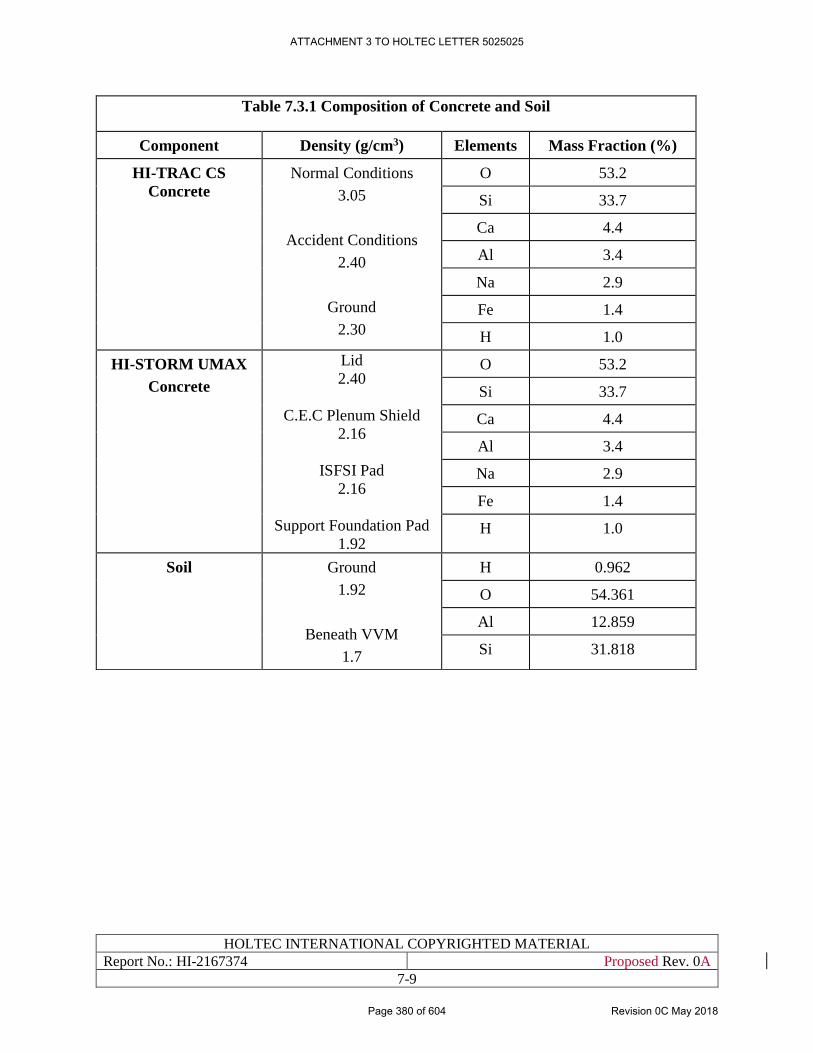
HOLTEC INTERNATIONAL COPYRIGHTED MATERIAL
Report No.: HI-2167374 Proposed Rev. 0A
7-9
Table 7.3.1 Composition of Concrete and Soil
Component Density (g/cm3) Elements Mass Fraction (%)
HI-TRAC CS
Concrete
Normal Conditions
3.05
Accident Conditions
2.40
Ground
2.30
O 53.2
Si 33.7
Ca 4.4
Al 3.4
Na 2.9
Fe 1.4
H 1.0
HI-STORM UMAX
Concrete
Lid
2.40
C.E.C Plenum Shield
2.16
ISFSI Pad
2.16
Support Foundation Pad
1.92
O 53.2
Si 33.7
Ca 4.4
Al 3.4
Na 2.9
Fe 1.4
H 1.0
Soil Ground
1.92
Beneath VVM
1.7
H 0.962
O 54.361
Al 12.859
Si 31.818
ATTACHMENT 3 TO HOLTEC LETTER 5025025
Page 380 of 604 Revision 0C May 2018
HOLTEC INTERNATIONAL COPYRIGHTED MATERIAL
Report No.: HI-2167374 Proposed Rev. 0A
7-10
7.4 SHIELDING ANALYSES METHODS AND RESULTS
7.4.1 Computational Methods and Data
Computational methods and associated data is provided in Section 5.4 in [1.0.6]. This section is
incorporated by reference into this document.
For doses and does rates from the entire ISFSI, the contribution from each individual VVM is
calculated, considering the distance of the VVM to the selected dose location, and then the results
for all VVMs are added.
7.4.2 Dose and Dose Rate Estimates
7.4.2.1 Normal Conditions
Dose rates around a HI-TRAC CS and around a single HI-STORM UMAX storage module, loaded
with the MPC-37 and design basis fuel, are presented in Table 7.4.1 and 7.4.2 respectively. It can
be concluded from the shielding analysis and results that the HI-TRAC CS and HI-STORM
UMAX provide suitable shielding in accordance with 10CFR72.128(a)(2) [1.0.5].
Dose rates, and annual dose from 500 loaded HI-STORM UMAX VVMs at the ISFSI for various
distances are presented in Table 7.4.3. Figure 7.4.3 shows ISFSI dose rates as a function of
distance.
The maximum controlled area boundary dose rate (assuming an occupancy of 2,000 hours per
year) is below the 25 mrem annual dose limit of 10CFR72.104 [1.0.5].
The nearest residence is 1.5 miles from the HI-STORE CIS Facility. The dose calculations
conservatively assume a full-time resident (8760 hours/year) is only 1000 meters from the nearest
loaded HI-STORM UMAX VVM. In the case of this nearest residence, the dose is calculated to
be below the 25 mrem annual dose limit prescribed in 10CFR72.104 [1.0.5].
Operations inside the Canister Transfer Building would not contribute significantly to dose rates
at the Controlled Area Boundary since the loaded canisters are shielded at all times by a shipping
or transfer cask. The operational steps to load a single storage module, together with the estimated
duration and dose rate for each step, and the cumulative crew dose for the entire operation, is
presented in Chapter 11 (Radiation Protection).
Occupational doses to individuals are administratively controlled to ensure that they are
maintained below 10CFR20.1201(a)(1) annual limits [7.4.1] i.e. the more limiting of:
i. The total effective dose equivalent being equal to 5 rem (0.05 Sv); or
ii. The sum deep-dose equivalent and the committed dose equivalent to any individual organ
or tissue other than the lens of the eye being equal to 50 rem (0.5 Sv).
Operational controls ensure the total effective dose equivalent to individual members of the public
from the licensed operation does not exceed 0.1 rem (1 mSv) in accordance with
10CFR20.1301(a)(1) [7.4.1] and that the dose in any unrestricted area from external sources does
not exceed 2 mrem (0.02 mSv) in any one hour 10CFR20.1301(a)(2) [7.4.1].
ATTACHMENT 3 TO HOLTEC LETTER 5025025
Page 381 of 604 Revision 0C May 2018
HOLTEC INTERNATIONAL COPYRIGHTED MATERIAL
Report No.: HI-2167374 Proposed Rev. 0A
7-11
TLDs are located at the Restricted Area fence and at the Controlled Area Boundary in accordance
with 10CFR20.1302 [7.4.1] to show compliance with the annual dose limit in 10CFR20.1301
[7.4.1].
7.4.2.2 Off-Normal and Accident Conditions
The only off-normal or accident condition applicable to the HI-STORM UMAX storage system is
the missile impact during construction next to a loaded canister. This condition is analyzed and
modeled in Section 5.1 and 5.3 of the HI-STORM UMAX FSAR [1.0.6]. The evaluation of this
missile impact event shows that the regulatory dose limits are met for this condition. The respective
sections are hereby incorporated by reference into this document.
The HI-TRAC CS is always carried with single failure proof equipment when loaded with a
canister, hence any drop accident that could result in an increase in does rates is not credible.
Further, unlike the HI-TRAC VW used in the HI-STORM UMAX FSAR, the HI-TRAC CS does
not contain any water as neutron absorber. A loss of water accident is therefore not possible.
However, under the fire accident condition, the outside of the cask would heat up significantly,
and while the outer steel shell would assure the overall integrity of the cask, and hence prevent
any significant loss of shielding function, the outer area of the shielding concrete may experience
some degradation. To model this in an analysis, shielding calculations are performed in which the
density of the HI-TRAC CS concrete is assumed to be substantially degraded as shown in Table
7.3.1. Results of the analyses are presented in Table 7.4.4, with the resulting accident dose
(assuming a 30 day accident duration) at 100 m from the cask showing compliance with the
requirements of 10CFR72.106 [1.0.5].
ATTACHMENT 3 TO HOLTEC LETTER 5025025
Page 382 of 604 Revision 0C May 2018
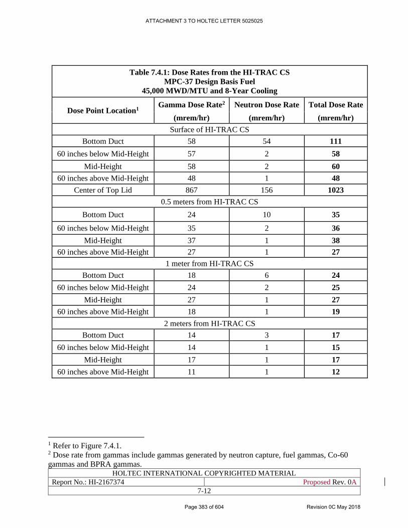
HOLTEC INTERNATIONAL COPYRIGHTED MATERIAL
Report No.: HI-2167374 Proposed Rev. 0A
7-12
Table 7.4.1: Dose Rates from the HI-TRAC CS
MPC-37 Design Basis Fuel
45,000 MWD/MTU and 8-Year Cooling
Dose Point Location1 Gamma Dose Rate2 Neutron Dose Rate Total Dose Rate
(mrem/hr) (mrem/hr) (mrem/hr)
Surface of HI-TRAC CS
Bottom Duct 58 54 111
60 inches below Mid-Height 57 2 58
Mid-Height 58 2 60
60 inches above Mid-Height 48 1 48
Center of Top Lid 867 156 1023
0.5 meters from HI-TRAC CS
Bottom Duct 24 10 35
60 inches below Mid-Height 35 2 36
Mid-Height 37 1 38
60 inches above Mid-Height 27 1 27
1 meter from HI-TRAC CS
Bottom Duct 18 6 24
60 inches below Mid-Height 24 2 25
Mid-Height 27 1 27
60 inches above Mid-Height 18 1 19
2 meters from HI-TRAC CS
Bottom Duct 14 3 17
60 inches below Mid-Height 14 1 15
Mid-Height 17 1 17
60 inches above Mid-Height 11 1 12
1 Refer to Figure 7.4.1. 2 Dose rate from gammas include gammas generated by neutron capture, fuel gammas, Co-60
gammas and BPRA gammas.
ATTACHMENT 3 TO HOLTEC LETTER 5025025
Page 383 of 604 Revision 0C May 2018
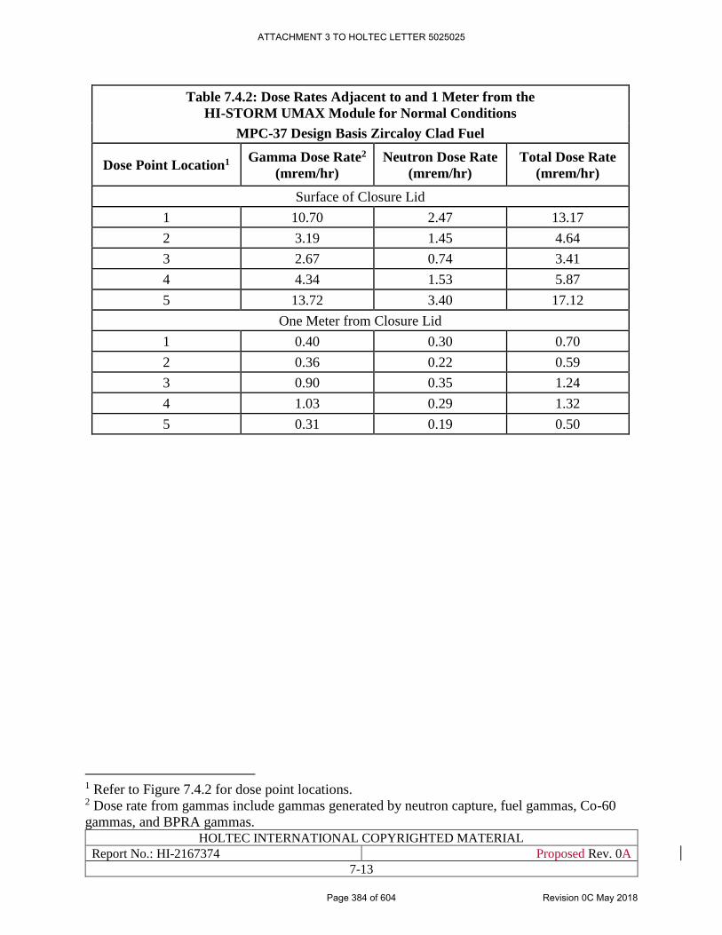
HOLTEC INTERNATIONAL COPYRIGHTED MATERIAL
Report No.: HI-2167374 Proposed Rev. 0A
7-13
Table 7.4.2: Dose Rates Adjacent to and 1 Meter from the
HI-STORM UMAX Module for Normal Conditions
MPC-37 Design Basis Zircaloy Clad Fuel
Dose Point Location1 Gamma Dose Rate2
(mrem/hr)
Neutron Dose Rate
(mrem/hr)
Total Dose Rate
(mrem/hr)
Surface of Closure Lid
1 10.70 2.47 13.17
2 3.19 1.45 4.64
3 2.67 0.74 3.41
4 4.34 1.53 5.87
5 13.72 3.40 17.12
One Meter from Closure Lid
1 0.40 0.30 0.70
2 0.36 0.22 0.59
3 0.90 0.35 1.24
4 1.03 0.29 1.32
5 0.31 0.19 0.50
1 Refer to Figure 7.4.2 for dose point locations. 2 Dose rate from gammas include gammas generated by neutron capture, fuel gammas, Co-60
gammas, and BPRA gammas.
ATTACHMENT 3 TO HOLTEC LETTER 5025025
Page 384 of 604 Revision 0C May 2018
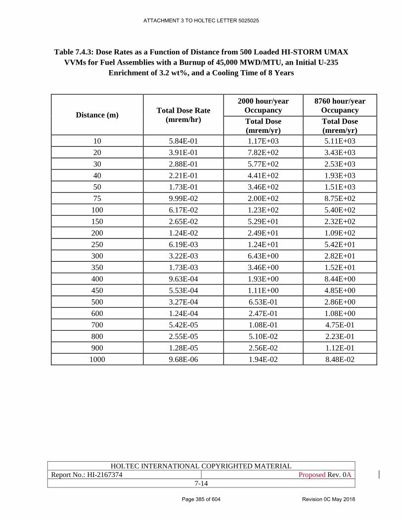
HOLTEC INTERNATIONAL COPYRIGHTED MATERIAL
Report No.: HI-2167374 Proposed Rev. 0A
7-14
Table 7.4.3: Dose Rates as a Function of Distance from 500 Loaded HI-STORM UMAX
VVMs for Fuel Assemblies with a Burnup of 45,000 MWD/MTU, an Initial U-235
Enrichment of 3.2 wt%, and a Cooling Time of 8 Years
Distance (m) Total Dose Rate
(mrem/hr)
2000 hour/year
Occupancy
8760 hour/year
Occupancy
Total Dose
(mrem/yr)
Total Dose
(mrem/yr)
10 5.84E-01 1.17E+03 5.11E+03
20 3.91E-01 7.82E+02 3.43E+03
30 2.88E-01 5.77E+02 2.53E+03
40 2.21E-01 4.41E+02 1.93E+03
50 1.73E-01 3.46E+02 1.51E+03
75 9.99E-02 2.00E+02 8.75E+02
100 6.17E-02 1.23E+02 5.40E+02
150 2.65E-02 5.29E+01 2.32E+02
200 1.24E-02 2.49E+01 1.09E+02
250 6.19E-03 1.24E+01 5.42E+01
300 3.22E-03 6.43E+00 2.82E+01
350 1.73E-03 3.46E+00 1.52E+01
400 9.63E-04 1.93E+00 8.44E+00
450 5.53E-04 1.11E+00 4.85E+00
500 3.27E-04 6.53E-01 2.86E+00
600 1.24E-04 2.47E-01 1.08E+00
700 5.42E-05 1.08E-01 4.75E-01
800 2.55E-05 5.10E-02 2.23E-01
900 1.28E-05 2.56E-02 1.12E-01
1000 9.68E-06 1.94E-02 8.48E-02
ATTACHMENT 3 TO HOLTEC LETTER 5025025
Page 385 of 604 Revision 0C May 2018
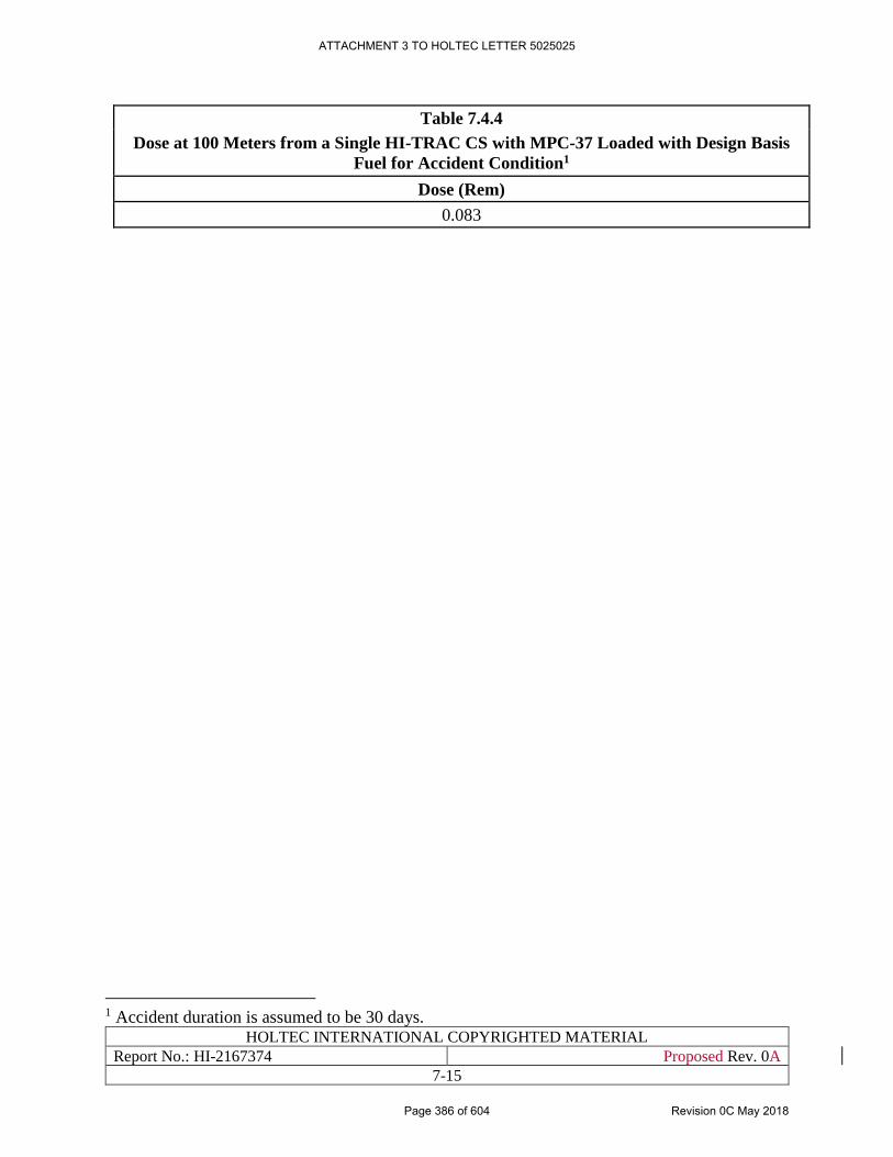
HOLTEC INTERNATIONAL COPYRIGHTED MATERIAL
Report No.: HI-2167374 Proposed Rev. 0A
7-15
Table 7.4.4
Dose at 100 Meters from a Single HI-TRAC CS with MPC-37 Loaded with Design Basis
Fuel for Accident Condition1
Dose (Rem)
0.083
1 Accident duration is assumed to be 30 days.
ATTACHMENT 3 TO HOLTEC LETTER 5025025
Page 386 of 604 Revision 0C May 2018
HOLTEC INTERNATIONAL COPYRIGHTED MATERIAL
Report No.: HI-2167374 Proposed Rev. 0A
7-16
Figure 7.4.1 [PROPRIETARY INFORMATION WITHHELD PER 10CFR2.390]
ATTACHMENT 3 TO HOLTEC LETTER 5025025
Page 387 of 604 Revision 0C May 2018
HOLTEC INTERNATIONAL COPYRIGHTED MATERIAL
Report No.: HI-2167374 Proposed Rev. 0A
7-17
Figure 7.4.2. [PROPRIETARY INFORMATION WITHHELD PER 10CFR2.390]
ATTACHMENT 3 TO HOLTEC LETTER 5025025
Page 388 of 604 Revision 0C May 2018
HOLTEC INTERNATIONAL COPYRIGHTED MATERIAL
Report No.: HI-2167374 Proposed Rev. 0A
7-18
Figure 7.4.2. [PROPRIETARY INFORMATION WITHHELD PER 10CFR2.390]
ATTACHMENT 3 TO HOLTEC LETTER 5025025
Page 389 of 604 Revision 0C May 2018
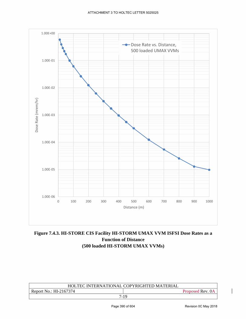
HOLTEC INTERNATIONAL COPYRIGHTED MATERIAL
Report No.: HI-2167374 Proposed Rev. 0A
7-19
Figure 7.4.3. HI-STORE CIS Facility HI-STORM UMAX VVM ISFSI Dose Rates as a
Function of Distance
(500 loaded HI-STORM UMAX VVMs)
1.00E-06
1.00E-05
1.00E-04
1.00E-03
1.00E-02
1.00E-01
1.00E+00
0 100 200 300 400 500 600 700 800 900 1000
Do
se R
ate
(mre
m/h
r)
Distance (m)
Dose Rate vs. Distance,500 loaded UMAX VVMs
ATTACHMENT 3 TO HOLTEC LETTER 5025025
Page 390 of 604 Revision 0C May 2018
HOLTEC INTERNATIONAL COPYRIGHTED MATERIAL
Report No.: HI-2167374 Proposed Rev. 0A
7-20
7.5 SUMMARY
In summary, the design of the facility satisfies all regulatory criteria and limits for radiological
protection, and provides acceptable means for limiting the exposure of the public to direct and
scattered radiation.
ATTACHMENT 3 TO HOLTEC LETTER 5025025
Page 391 of 604 Revision 0C May 2018
HOLTEC INTERNATIONAL COPYRIGHTED MATERIAL
Report No.: HI-2167374 Proposed Rev. 0A
8-1
CHAPTER 8: CRITICALITY EVALUATION
8.0 INTRODUCTION
The criticality safety qualification of the canisters for installation at the HI-STORE CIS facility is
considered in this chapter. An essential commitment in this SAR is that only those canisters that
have been certified and loaded under the HI-STORM UMAX docket (#72-1040) may be stored at
the HI-STORE facility. Reactivity of the stored fuel in a canister depends foremost on the
configuration of the fuel basket and to a lesser extent on the circumscribing Enclosure Vessel
around the basket. Because the canister shipped from the originating site has already been
designed, built, loaded and certified to an NRC-issued Technical Specification, the subcriticality
of the canister is pre-established. Thus, for example, for the canisters denoted as MPC-37 and
MPC-89, the substantiating criticality safety demonstration is in the HI-STORM FW FSAR
[1.3.7]. This qualification as also been utilized in the regulatory review and certification for storage
in the HI-STORM UMAX system in docket # 72-1040. Since the same HI-STORM UMAX system
is proposed to be deployed at HI-STORE, the criticality safety determination by the NRC in docket
# 72-1040 remains applicable. This axiomatic qualification of the canisters will remain valid unless
the canister and its fuel basket are physically altered during their transport or handling to the HI-
STORE facility which will summarily disqualify them from storage under the HI-STORE CIS
docket.
All references are placed within square brackets in this report and are compiled in Chapter 19 (last chapter)
ATTACHMENT 3 TO HOLTEC LETTER 5025025
Page 392 of 604 Revision 0C May 2018
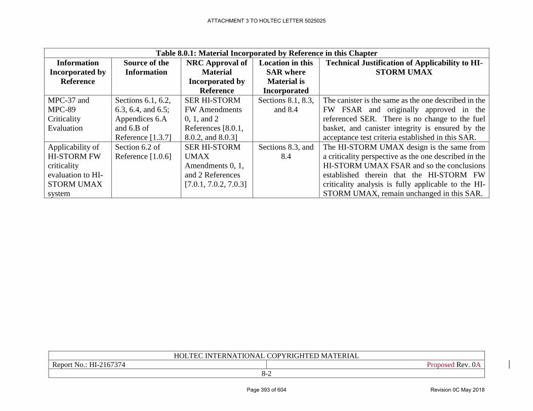
HOLTEC INTERNATIONAL COPYRIGHTED MATERIAL
Report No.: HI-2167374 Proposed Rev. 0A
8-2
Table 8.0.1: Material Incorporated by Reference in this Chapter
Information
Incorporated by
Reference
Source of the
Information
NRC Approval of
Material
Incorporated by
Reference
Location in this
SAR where
Material is
Incorporated
Technical Justification of Applicability to HI-
STORM UMAX
MPC-37 and
MPC-89
Criticality
Evaluation
Sections 6.1, 6.2,
6.3, 6.4, and 6.5;
Appendices 6.A
and 6.B of
Reference [1.3.7]
SER HI-STORM
FW Amendments
0, 1, and 2
References [8.0.1,
8.0.2, and 8.0.3]
Sections 8.1, 8.3,
and 8.4
The canister is the same as the one described in the
FW FSAR and originally approved in the
referenced SER. There is no change to the fuel
basket, and canister integrity is ensured by the
acceptance test criteria established in this SAR.
Applicability of
HI-STORM FW
criticality
evaluation to HI-
STORM UMAX
system
Section 6.2 of
Reference [1.0.6]
SER HI-STORM
UMAX
Amendments 0, 1,
and 2 References
[7.0.1, 7.0.2, 7.0.3]
Sections 8.3, and
8.4
The HI-STORM UMAX design is the same from
a criticality perspective as the one described in the
HI-STORM UMAX FSAR and so the conclusions
established therein that the HI-STORM FW
criticality analysis is fully applicable to the HI-
STORM UMAX, remain unchanged in this SAR.
ATTACHMENT 3 TO HOLTEC LETTER 5025025
Page 393 of 604 Revision 0C May 2018
HOLTEC INTERNATIONAL COPYRIGHTED MATERIAL
Report No.: HI-2167374 Proposed Rev. 0A
8-3
8.1 CRITICALITY DESIGN CRITERIA AND FEATURES
8.1.1 Criteria
The acceptance criteria for criticality evaluations for the HI-STORM UMAX system utilized at
the HI-STORE facility are presented in Chapter 4 of this SAR.
8.1.2 Features
Section 6.1 of the HI-STORM FW FSAR [1.3.7] is incorporated by reference into this SAR, and
describes all the criticality design features of the canisters which maintain the stored fuel in a sub-
critical condition.
ATTACHMENT 3 TO HOLTEC LETTER 5025025
Page 394 of 604 Revision 0C May 2018
HOLTEC INTERNATIONAL COPYRIGHTED MATERIAL
Report No.: HI-2167374 Proposed Rev. 0A
8-4
8.2 STORED MATERIAL SPECIFICATIONS
The fuel assemblies allowable for storage in the HI-STORM UMAX VVMs at the HI-STORE
facility are described in Section 4.1.
ATTACHMENT 3 TO HOLTEC LETTER 5025025
Page 395 of 604 Revision 0C May 2018
HOLTEC INTERNATIONAL COPYRIGHTED MATERIAL
Report No.: HI-2167374 Proposed Rev. 0A
8-5
8.3 EVALUATION
During storage conditions in the HI-STORM UMAX system, the maximum keff will be
significantly below the limiting maximum keff since the MPC is internally dry. Under this
condition, the configuration is very similar in all other HI-STORM models, which consists of an
internally dry MPC, an air gap between the MPC and the overpack, a steel shell or shells and
concrete (above-ground) or soil (underground). Results for the HI-STORM UMAX VVM would
therefore be practically identical to the results listed for storage conditions in Chapter 6 of the
canister’s native FSAR (such as the HI-STORM FW FSAR [1.3.7] for the canisters subsequently
certified under the HI-STORM UMAX FSAR [1.0.6], which are now included in this site-specific
license. Any small differences in results would not affect the principal conclusions, since the
maximum keff under storage conditions (dry inert environment) is substantially below the
regulatory limit. It should be noted that the analysis for the canisters in the various HI-STORM
models conservatively assumes that the gap between the canister and the HI-STORM is flooded
with water, thus increasing the neutron reflection compared to a dry cavity [8.0.1, Section 7].
Flooding under accident conditions of the HI-STORM UMAX is therefore also covered by the
calculations for the HI-STORM FW (see also Subsection 8.3.2 below). All other normal, off-
normal and accident conditions in the HI-STORM UMAX system at HI-STORE are identical to
or less severe than invoked for certification in the generic dockets (such as HI-STORM FW) which
consider bounding loadings for the entire continental United States.
In summary, the limiting condition for storage of the canisters certified in the generic docket for
HI-STORM UMAX (Docket # 72-1040) is identical to their storage in HI-STORM UMAX at HI-
STORE from a criticality perspective, and all other normal, off-normal and accident conditions are
identical or equivalent between the two dockets from a criticality perspective. Therefore, the
criticality safety of the canisters certified in docket # 72-1040 is a priori ensured for storing those
canisters at HI-STORE. No additional calculations to demonstrate criticality safety are required
for storing such canisters in the HI-STORM UMAX system at HI-STORE.
8.3.1 Model Configuration
The model configuration including material properties for the criticality analysis is incorporated
by reference from Section 6.3 of [1.3.7], as described in Table 8.0.1 of this SAR.
8.3.2 Accidental Criticality
10CFR72.124(a) requires that at least two unlikely events (changes) must occur before a criticality
accident is possible. The HI-STORM UMAX implementation at the HI-STORE facility would in
fact require three such events before an accident is possible, and is therefore in compliance with
the abovementioned regulation. The three unlikely events applicable to the facility are as follows
• The site is in a dry area with no flood plains (see [1.0.4], Subsection 3.5.4). Even the 100,000
year flood is estimated to be only 4.8 inches (see [1.0.4], Subsection 4.5.3), and at that level
the design of the systems would prevent any flooding of the CECs, since the lowest points of
the air inlets or outlets are higher above the ground than this value. Further, the pads are
designed and constructed so that rainwater will run off and not accumulate. A water spray was
performed on the first HI-STORM UMAX systems installed at a site to demonstrate this after
installation. Based on this, a flooding of the CECs is unlikely, in fact considered not credible.
ATTACHMENT 3 TO HOLTEC LETTER 5025025
Page 396 of 604 Revision 0C May 2018
HOLTEC INTERNATIONAL COPYRIGHTED MATERIAL
Report No.: HI-2167374 Proposed Rev. 0A
8-6
• However, even if a CEC would be flooded, the internal cavity of the canister with the basket
and fuel would remain dry, and hence the reactivity would remain very low. The canister is
seal-welded, and the integrity of the canister is verified during the acceptance tests when it
enters the site. For the initially licensed period of each canister, this gives assurance that a leak
of the canister that would allow ingress of water is unlikely. For longer storage times beyond
the initially licensed period, an aging management program is applied, designed to detect and
mitigate any such leaks, making water inleakage also an unlikely event.
• Finally, the fact that canisters are not loaded on-site, but always be delivered to the site in a
10CFR71 approved transportation cask, together with the acceptance tests for each transport
cask, presents the third barrier, which would prevent a criticality accident even in the unlikely
event that both the CEC and the canister would be flooded:
o The transport regulations require that the package remains subcritical under normal
conditions when flooded with pure water.
▪ For BWR fuel that is essentially met by default, since canisters are loaded in a
pool with fresh water
▪ For PWR fuel, the requirements for transportation in the HI-STAR 190 require
burnup credit so that the same requirement is met, i.e. subcriticality when
flooded with fresh water
o The transportation cask to be used for the approved canisters (HI-STAR 190) will also
be qualified for High Burnup Fuel, where fuel damage is possible. In that case, the
criticality safety evaluation for the package does not assume flooding of the canister.
However, the acceptance tests for the acceptance of the canister on site excludes
canisters from transports that have undergone any accident condition, as described in
the Facility Technical Specifications. This scenario is therefore not applicable here.
Based on this, even for a flooded canister, accidental criticality is unlikey.
Overall, at least three unlikely (or non-credible) events would be required before accidental
criticality could be possible at the HI-STORE facility. The facility is therefore in compliance with
10CFR72.124(a).
ATTACHMENT 3 TO HOLTEC LETTER 5025025
Page 397 of 604 Revision 0C May 2018
HOLTEC INTERNATIONAL COPYRIGHTED MATERIAL
Report No.: HI-2167374 Proposed Rev. 0A
8-7
8.4 APPLICANT CRITICALITY ANALYSIS
The criticality analysis for the MPC-37 and MPC-89 is incorporated by reference from Section 6.4
of [1.3.7], as described in Table 8.0.1 of this SAR, including the computer program utilized,
multiplication factor, and benchmark comparison. The discussion of how these HI-STORM FW
results apply to the HI-STORM UMAX system is incorporated by reference from Section 6.2 of
[1.0.6]. The configuration and confinement of the canisters are unchanged based on the discussion
in Chapter 9, so the existing analysis is fully applicable to the HI-STORE CIS Facility.
ATTACHMENT 3 TO HOLTEC LETTER 5025025
Page 398 of 604 Revision 0C May 2018
HOLTEC INTERNATIONAL COPYRIGHTED MATERIAL
Report No.: HI-2167374 Proposed Rev. 0A
8-8
8.5 CRITICALITY MONITORING
10CFR72.124(c) requires criticality monitoring during operations unless the fuel is already
packaged in the storage configuration. At the HI-STORE facility, no wet fuel operations are
performed, and fuel will always be in the dry and sealed canisters, i.e. in the storage configuration.
Hence criticality monitoring per 10CFR72.124(c) is not required.
ATTACHMENT 3 TO HOLTEC LETTER 5025025
Page 399 of 604 Revision 0C May 2018
HOLTEC INTERNATIONAL COPYRIGHTED MATERIAL
Report No.: HI-2167374 Proposed Rev. 0A
9-1
CHAPTER 9: CONFINEMENT EVALUATION
9.0 INTRODUCTION
The confinement safety of the HI-STORE CIS facility is considered in this chapter. In accordance
with NUREG-1567 [1.0.3] the following areas are addressed
• Potential of the release of radioactive material
• Monitoring systems
• Protection of stored materials from degradation
The evaluation of any potential release considers both the storage systems and the operational
activities.
Additionally, for the storage systems, aspects of receipt inspections for systems delivered to the
site, and long term aging are briefly addressed, with full details presented in other chapters of this
SAR and referenced appropriately.
With respect to the storage systems themselves, only radioactive materials in seal-welded canisters
are accepted and placed into storage in this facility. Further, this is limited to those canisters that
are certified for storage in the HI-STORM UMAX docket (Docket #72-1040). The HI-STORM
UMAX FSAR references the HI-STORM FW docket (Docket # 72-1032). Hence this chapter
contains references to sections of the FSAR of the HI-STORM UMAX and sections of FSAR of
the HI-STORM FW. The sections that are included by reference from the HI-STORM UMAX
FSAR and HI-STORM FW are listed in Table 9.0.1.
All references are in placed within square brackets in this report and are compiled in Chapter 19 (last chapter)
ATTACHMENT 3 TO HOLTEC LETTER 5025025
Page 400 of 604 Revision 0C May 2018
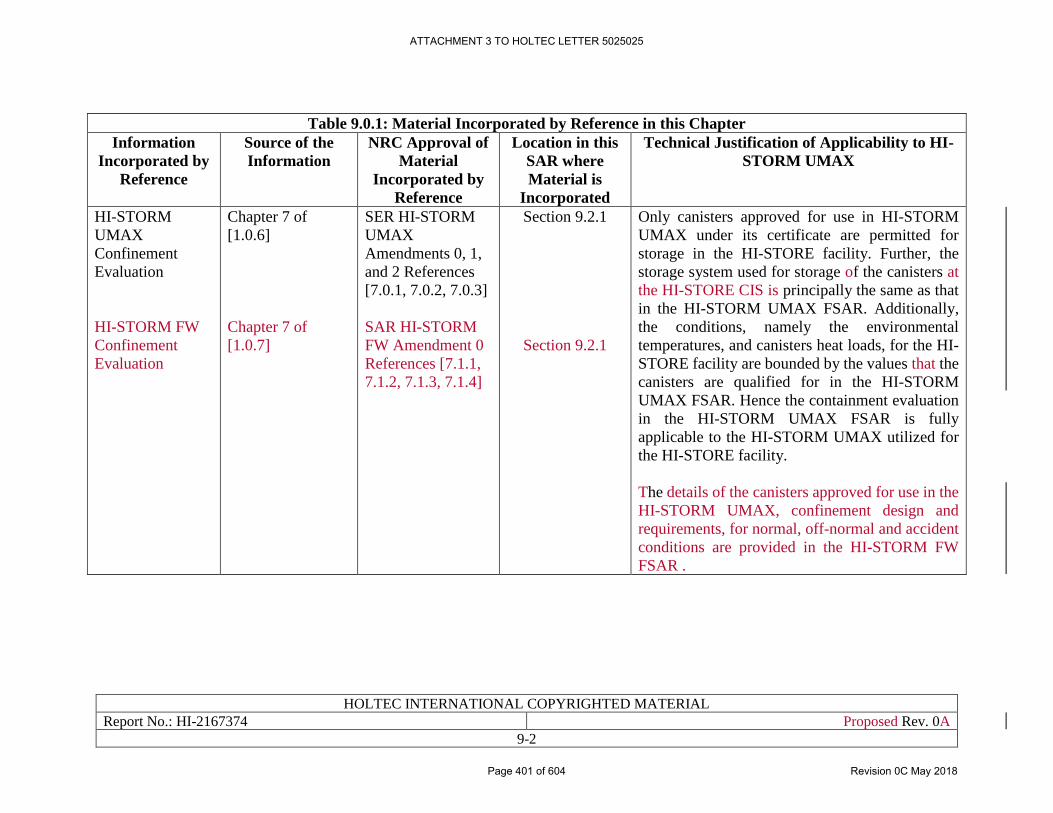
HOLTEC INTERNATIONAL COPYRIGHTED MATERIAL
Report No.: HI-2167374 Proposed Rev. 0A
9-2
Table 9.0.1: Material Incorporated by Reference in this Chapter
Information
Incorporated by
Reference
Source of the
Information
NRC Approval of
Material
Incorporated by
Reference
Location in this
SAR where
Material is
Incorporated
Technical Justification of Applicability to HI-
STORM UMAX
HI-STORM
UMAX
Confinement
Evaluation
HI-STORM FW
Confinement
Evaluation
Chapter 7 of
[1.0.6]
Chapter 7 of
[1.0.7]
SER HI-STORM
UMAX
Amendments 0, 1,
and 2 References
[7.0.1, 7.0.2, 7.0.3]
SAR HI-STORM
FW Amendment 0
References [7.1.1,
7.1.2, 7.1.3, 7.1.4]
Section 9.2.1
Section 9.2.1
Only canisters approved for use in HI-STORM
UMAX under its certificate are permitted for
storage in the HI-STORE facility. Further, the
storage system used for storage of the canisters at
the HI-STORE CIS is principally the same as that
in the HI-STORM UMAX FSAR. Additionally,
the conditions, namely the environmental
temperatures, and canisters heat loads, for the HI-
STORE facility are bounded by the values that the
canisters are qualified for in the HI-STORM
UMAX FSAR. Hence the containment evaluation
in the HI-STORM UMAX FSAR is fully
applicable to the HI-STORM UMAX utilized for
the HI-STORE facility.
The details of the canisters approved for use in the
HI-STORM UMAX, confinement design and
requirements, for normal, off-normal and accident
conditions are provided in the HI-STORM FW
FSAR .
ATTACHMENT 3 TO HOLTEC LETTER 5025025
Page 401 of 604 Revision 0C May 2018
HOLTEC INTERNATIONAL COPYRIGHTED MATERIAL
Report No.: HI-2167374 Proposed Rev. 0A
9-3
9.1 ACCEPTANCE CRITERIA
The acceptance criteria for confinement evaluations are referenced in Section 4.3 of this SAR.
ATTACHMENT 3 TO HOLTEC LETTER 5025025
Page 402 of 604 Revision 0C May 2018
HOLTEC INTERNATIONAL COPYRIGHTED MATERIAL
Report No.: HI-2167374 Proposed Rev. 0A
9-4
9.2 CONFINEMENT OF RADIOACTIVE MATERIALS
9.2.1 Storage Systems
Continued Storage
Only canisters approved for use in HI-STORM UMAX under its certificate are permitted for
storage in the HI-STORE facility. Table 1.0.4 identifies the canisters approved for storage in this
docket. Further details on the canisters and the applicability of the containment evaluations from
the HI-STORM UMAX FSAR to the HI-STORE facility are discussed below
Confinement of all radioactive materials in all HI-STORM vertical ventilated modules is provided
by the canister’s Enclosure Vessel which has no mechanical joints, flanges, gaskets and the like
that may be subject to leakage. The confinement boundary as defined in Paragraph 2.3.3.4 in the
HI-STORM UMAX FSAR[1.0.6] consists of the MPC shell, MPC baseplate, MPC lid, port cover
plates, closure ring, and associated welds. The pressure boundary of the canister consists of
radiographed weld seams and ultrasonically tested plate and forging stock. Only high ductility
stainless steel alloy with excellent fracture strength properties at low service temperatures are used
in the manufacture of the canisters eligible for storage at HI-STORE.
All normal, off-normal and accident conditions relevant to confinement integrity for which the
canister is certified in the HI-STORM UMAX docket are equal to or less severe at the HI-STORE
facility. Therefore, there are no new conditions for the HI-STORE CIS facility that would require
additional confinement analyses. With respect to the applicability of the containment evaluation
from the HI-STORM UMAX note that the continued confinement integrity of a canister is
influenced by the stress field that exists in its Enclosure Vessel during its storage state and by the
occurrence of any stress-inducing mechanical loading event. These are discussed below:
• The stresses that the canister will experience at the HI-STORE facility will be bounded by
those for which it is certified in the HI-STORM UMAX docket because:
o The Design Basis Heat load (see Tables 4.1.1 and 4.1.2) for all canisters eligible for storage
in HI-STORE is lower than that for the canisters certified in Docket # 72-1040 (see Tables
2.1.8 and 2.1.9 in the HI-STORM UMAX FSAR[1.0.6]). It follows that the internal gas
temperature in the former will be less than the latter. Therefore, it follows that the pressure
in the canisters and hence any pressure-induced stresses will be lower in HI-STORE
canisters than their certification-basis in the HI-STORM UMAX FSAR.
o The canisters in the HI-STORM UMAX docket are certified for the entire range of ambient
temperatures that exist in the lower 48 states in the United States. Therefore, the licensing-
basis ambient temperature range applicable to the canister’s general certification in the HI-
STORM UMAX docket bounds the conditions at the HI-STORE site.
• As in the HI-STORM UMAX FSAR, all lifting and handling operations involving canisters at
the HI-STORE facility are performed with single failure proof equipment. Hence there are no
additional mechanical loading events that would affect the confinement function of the
canisters.
In summary, the storage conditions at the HI-STORE site are identical to, or more benign (less
challenging) than the certification-basis conditions for the canisters in the generic HI-STORM
ATTACHMENT 3 TO HOLTEC LETTER 5025025
Page 403 of 604 Revision 0C May 2018
HOLTEC INTERNATIONAL COPYRIGHTED MATERIAL
Report No.: HI-2167374 Proposed Rev. 0A
9-5
UMAX docket (# 72-1040). Therefore, the safety conclusions reached with respect to the system
confinement integrity in the HI-STORM UMAX FSAR [1.0.6] also apply to the canisters stored
at HI-STORE.
Confinement safety of the canisters in this docket is therefore demonstrated by reference to
confinement determination reached in the HI-STORM UMAX FSAR [1.0.6].
Receipt Inspection
The canister must meet the following criteria that pertain to its continued condition of no-credible-
leakage upon arrival at the HI-STORE facility:
• The canister records must be provided to the HI-STORE facility personnel prior to
shipment of a canister. These records must be reviewed and any applicable 10CFR72.48
screenings or evaluations written against the canister’s original licensing basis evaluated
against the HI-STORE site specific license to determine if a change requiring NRC
approval is necessary.
• The canister was not subject to any incident beyond the normal conditions which the
package has been qualified to pursuant to 10CFR71.71.
• The canister passes the leak test and other receipt inspections set forth in this Chapter 10
of this FSAR at the HI-STORE receiving area.
A canister that meets the above conditions is deemed to continue to meet the no-credible-leakage
criteria to which it has been certified in the HI-STORM UMAX docket (# 72-1040). Although the
HI-STORM UMAX confinement boundary includes the MPC lid to shell weld, this weld is
covered with a redundant closure ring. Therefore, the leak testing described is performed only on
that redundant closure ring of the confinement boundary. However, due to the restrictions on no
transport incident and the fact that the storage conditions have been demonstrated to pose no
challenge to the confinement boundary, confirmation that the closure ring is intact provides
reasonable assurance that the inner lid-to-shell weld remains a fully qualified confinement
boundary.
Prior to receipt, the canister storage operation is bounded by the onsite storage system SAR. During
transportation to the HI-STORE, canister transportation operations are bounded by the HI STAR
190 SAR. Adherence to these criteria demonstrates confinement safety prior to receipt at the HI-
STORE.
Long Term Storage and Aging Management
While a canister is still within its originally licensed period in accordance with the certificate it
was originally approved to, no further confinement considerations are necessary, since the canister
retains its no-credible-leakage status based on the original confinement evaluation and the receipt
inspection discussed above. However, it is expected that canisters will be stored at the HI-STORE
CIS facility beyond this initial period. Any canister where the storage life exceeds 20 years will
need to comply with the aging management requirements outlined in Chapter 18 of this SAR.
Compliance with these requirements will ensure that any conditions that could be detrimental to
the confinement function of the canister will be identified, and, if necessary, mitigated.
9.2.2 Operational Activities
ATTACHMENT 3 TO HOLTEC LETTER 5025025
Page 404 of 604 Revision 0C May 2018
HOLTEC INTERNATIONAL COPYRIGHTED MATERIAL
Report No.: HI-2167374 Proposed Rev. 0A
9-6
With respect to the confinement of the radioactive material, the operational activities can be
grouped into the following three steps/conditions
• MPC is still inside the intact containment boundary of the transportation cask that it is
delivered in
• Receipt inspection activities on each canister, and, if the inspection criteria are met,
opening of the transport cask containment boundary.
• Operational activities to place the accepted canister into storage
These steps are discussed in further detail below.
While the canister is still inside the transportation cask, the canister is still considered the
confinement boundary for the material. However, the receipt inspections need to be passed to
confirm that the confinement boundary has not degraded during the transport phase. Until this is
concluded, the containment boundary of the transportation cask serves as an additional measure to
assure the confinement of the material in the canisters.
During the receipt inspection and opening of each transportation cask containing, the activities that
are performed, and the possibility (or lack thereof) of any release of radioactive material is as
follows:
• One of the vent/drain ports of the transportation cask is opened to allow access to the small
free volume between the canister and the cask. For this activity the port is covered by
appropriate means, so that in the unlikely event that the volume would contain any
radioactive material, it would not be released into the local work area (transfer building),
but appropriately collected.
• A gas sample is taken from this volume and tested for the presence of fission products,
namely Krypton-85.
o If any fission products are detected, the port will be resealed, and the cask will be
classified as “not acceptable”. All gas samples containing fission products will be
collected and tracked in accordance with Section 10.3. Cask transfer operations will
be terminated for casks not meeting the acceptance criteria. For further processing
of casks that are not acceptable see Subsection 10.3.3.
o Full details of the receipt inspection test including instrumentation and acceptance
criteria are outlined in Section 10.3.
o If the acceptance criteria outlined in Chapter 10 are not met the transportation cask
is not opened and is not accepted at the HI-STORE facility
• If no fission products are detected, the free volume is evacuated, flushed with nitrogen and
then tested for traces of helium that could be an indication of any leakage of the helium-
filled canister in the cask (see Paragraph 10.3.3.2 for details). The gas extracted from the
volume during the evacuation and helium testing is also collected and tested for any fission
products before being released.
o If the leak tightness of the canister cannot be ascertained, or if fission products are
detected, the port will be resealed, and the cask will be classified as “not
ATTACHMENT 3 TO HOLTEC LETTER 5025025
Page 405 of 604 Revision 0C May 2018
HOLTEC INTERNATIONAL COPYRIGHTED MATERIAL
Report No.: HI-2167374 Proposed Rev. 0A
9-7
acceptable”. All gas samples containing fission products will be collected and
tracked in accordance with Subsection 10.3.3 For further processing of casks that
are not acceptable see Subsection 10.3.3 .
From this step, even in the unlikely event that fission products were detected, these would only be
small amounts from the small free space between the cask and the canisters, and the process is
designed to ensure that those are collected. A release into the building or the environment is
therefore not considered credible.
As discussed in Subsection 9.2.1 above, all radioactive material is stored and handled in seal
welded canisters, and as presented in Chapter 1, all handling operations are performed either with
single-failure-proof cranes, or using suitable impact limiters. Hence once the canisters have passed
the receipt inspection, also discussed in Subsection 9.2.1, there is no credible normal or accident
situation that could challenge the integrity of the canister confinement integrity and result in a
release of any radioactivity.
Overall, from all operational activities, no credible events are identified that would result in a
release of any radioactive materials into the work areas or the environment.
ATTACHMENT 3 TO HOLTEC LETTER 5025025
Page 406 of 604 Revision 0C May 2018
HOLTEC INTERNATIONAL COPYRIGHTED MATERIAL
Report No.: HI-2167374 Proposed Rev. 0A
9-8
9.3 POOL AND WASTE MANAGEMENT FACILITIES
9.3.1 Pool Facilities
HI-STORE CIS contains no pool or any other water-based storage or handling facility.
9.3.2 Waste Management Facilities
No specific facilities are needed for the management of radioactive waste at the HI-STORE
facility, since no, or only insignificant amounts of, radioactive waste is generated in the facility,
as discussed in the following:
• All fuel is handled in seal-welded canisters with no credible leakage, and all activities and
operations with the canisters are designed to maintain this condition
• The transportation casks received with the canisters at the site would almost certainly have
been loaded with canisters in a dry facility, hence contamination of the casks is not
expected.
o Nevertheless, transport casks are checked for contamination upon receipt and
during processing and extraction of the canisters, and in the unlikely event that any
contamination would be detected, this would be removed with standard methods,
and any materials related to this operation would be separately collected, and
transported off-site for appropriate disposal.
• Small gas samples are taken during the receipt inspection of the canisters. The samples will
be kept in closed containers until the measurements have confirmed the absence of any
fission gases. In the unlikely event that fission gases would be detected, the gas samples
will be transported off-site for appropriate disposal.
• There is no other radioactive material that is being handled openly throughout the facility.
ATTACHMENT 3 TO HOLTEC LETTER 5025025
Page 407 of 604 Revision 0C May 2018
HOLTEC INTERNATIONAL COPYRIGHTED MATERIAL
Report No.: HI-2167374 Proposed Rev. 0A
9-9
9.4 CONFINEMENT MONITORING
9.4.1 Storage Confinement Systems
9.4.1.1 Closure Seal Monitoring System
All radioactive material is stored in seal-welded canisters, and consistent with its operation and
approval under the initial certificate that those canisters are loaded under, no monitoring of the
closure seals is required for the initial licensing period. The continuous confinement of the
canisters beyond their initial licensing period is addressed in the Aging Management Program in
Chapter 18, which uses a Canister Aging Management Program to inspect and monitor, as
described in Section 18.5.
9.4.1.2 Continuous Monitoring System
All material at the ISFSI is stored in seal welded canisters, qualified to have no credible leakage
per ISG-18. Hence no monitoring of airborne radiation is needed in and around the storage area.
For the canister transfer inside the CTB, there is also no expectation that any release of
radioactivity would occur, so no monitoring of airborne radiation is required. Nevertheless,
radiation detectors able to detect airborne radiation may be used in the CTB as additional measure.
9.4.2 Effluents
The HI-STORE CIS facility does not generate any radioactive effluent, hence no effluent
monitoring system is required.
Additionally, in the absence of any effluent, there is no potential for transport of radioactive
materials to the environment through any aquifer under the site.
ATTACHMENT 3 TO HOLTEC LETTER 5025025
Page 408 of 604 Revision 0C May 2018
HOLTEC INTERNATIONAL COPYRIGHTED MATERIAL
Report No.: HI-2167374 Proposed Rev. 0A
9-10
9.5 PROTECTION OF STORED MATERIALS FROM DEGRADATION
9.5.1 Confinement Casks or Systems
All radioactive material is stored in seal-welded canisters, in an inert atmosphere, and consistent
with its operation and approval under the initial certificate that those canisters are loaded under,
no degradation of its content is to be expected. Any potential degradation beyond the previously
approved canister licensed life is addressed in the Aging Management Program in Sections 18.5,
18.11, 18.12, and 18.14.
9.5.2 Pool and Waste Management Systems
HI-STORE CIS contains no pool or any other water-based storage or handling facility.
ATTACHMENT 3 TO HOLTEC LETTER 5025025
Page 409 of 604 Revision 0C May 2018
HOLTEC INTERNATIONAL COPYRIGHTED MATERIAL
Report No.: HI-2167374 Proposed Rev. 0A
9-11
9.6 SUMMARY
In summary,
• This chapter describes confinement structures, systems and components, and their evaluation
and effectiveness.
• The confinement of all radioactive material is provided by seal-welded canisters, loaded and
closed under their original certificates. The confinement is verified upon receipt inspection
through leak testing to the leaktight criteria in accordance with Section 10.3.
• The operation of the HI-STORE CIS facility generates no radioactive effluents. There is no
potential for transport of radioactive materials to the environment through any aquifer.
• No release of any radioactive material is expected from the facility and its operation, hence no
additional dose from released material is considered in the evaluations in Chapter 11.
• No radiation monitoring system is required.
• The stored material is protected against degradation due to its storage in an inert atmosphere.
• The confinement systems will reasonably maintain confinement under normal, off-normal and
accident conditions.
ATTACHMENT 3 TO HOLTEC LETTER 5025025
Page 410 of 604 Revision 0C May 2018
HOLTEC INTERNATIONAL COPYRIGHTED MATERIAL
Report No. HI-2167374 Proposed Rev. 0A
10-1
CHAPTER 10: CONDUCT OF OPERATIONS EVALUATION
10.0 INTRODUCTION
This chapter discusses the organization and procedures established by Holtec International
(Holtec) for the operation and decommissioning of an Independent Spent Fuel Storage Installation
(ISFSI) at the HI-STORE CIS site. Included are descriptions of organizational structure, testing,
training programs, normal operations, emergency planning, and security safeguards.
All references are placed within square brackets in this report and are compiled in Chapter 19 of this report.
ATTACHMENT 3 TO HOLTEC LETTER 5025025
Page 411 of 604 Revision 0C May 2018
HOLTEC INTERNATIONAL COPYRIGHTED MATERIAL
Report No. HI-2167374 Proposed Rev. 0A
10-2
10.1 ORGANIZATIONAL STRUCTURE
This section describes the organization that is responsible for long term storage of spent nuclear
fuel at the HI-STORE CIS facility. Lines of authority, responsibility, and communication shall be
defined and established throughout highest management levels, intermediate levels, and all
operating organization positions. These relationships shall be documented and updated, as
appropriate, in organizational charts, functional descriptions of departmental responsibilities and
relationships, and job descriptions for key personnel positions, or in equivalent forms of
documentation. This chapter is included in this SAR to fulfill the requirements in 10CFR72.24(h)
and 72.28(c).
10.1.1 Corporate and On-Site Organization
The Holtec Corporate Executive responsible for the HI-STORE CIS facility (hereafter referred to
as the Corporate Executive) has overall responsibility for safe operation of the site.
The Holtec HI-STORE CIS Site Manager (hereafter referred to as the Site Manager) reports to the
Corporate Executive. The Site Manager is responsible for safe operation of the site, maintaining
personnel trained and qualified in accordance with the HI-STORE Site Specialist Training
Program [10.1.1], day-to-day implementation of the Holtec Quality Assurance Manual [12.0.1],
and operation of all HI-STORE CIS facility structures, systems and components that are important
to safety. This position provides direction for the safe operation, maintenance, radiation
protection, training and qualification, and security of the site and personnel.
To assure continuity of operation and organizational responsiveness to off-normal situations, a
normal order of succession and delegation of authority will be established. The Site Manager will
designate, in writing, personnel who are qualified to act in his/her absence.
The organization charts shown in Figures 10.4.1 and 10.4.2 represent the planned organizational
relationships throughout the life of the facility.
10.1.2 Support Staff (ISFSI Specialists)
Support staff will be available by either corporate staff, on-site staff or contract personnel to
provide support and expertise to the Site Manager in the following areas:
• Quality Assurance: Responsible for the implementation of the requirements of the Holtec
Quality Assurance Manual [12.0.1], including the maintenance of appropriate records. The
staff will ensure that the appropriate steps are added to site procedures for operation and
maintenance to ensure that all activities are performed in accordance with the site license;
• Engineering: The site nuclear compliance engineer is responsible for the oversight of the
facility modifications. Engineering support staff, either on or off-site, is provided to support
the site nuclear engineer.
• Radiation Protection Manager: Responsible for radiation safety at the HI-STORE CIS
facility, for the planning and direction of the facility radiation protection and ALARA
programs and procedures, as well as the operation of the health physics laboratory.
ATTACHMENT 3 TO HOLTEC LETTER 5025025
Page 412 of 604 Revision 0C May 2018
HOLTEC INTERNATIONAL COPYRIGHTED MATERIAL
Report No. HI-2167374 Proposed Rev. 0A
10-3
• Operating Personnel: Responsible for the receipt, inspection and transfer of canisters
arriving onsite in accordance with site procedures.
• Maintenance: Responsible for mechanical, electrical and instrument maintenance for
buildings, fencing, mechanical equipment and all other site equipment. Also provide
operations coverage for those periods of time in which loaded canisters are handled and
routine site maintenance and surveillance when canisters are not being handled. May also
provide maintenance as needed for operation of railroad locomotives from the railroad
mainline. Shall be responsible for ensuring that appropriate records are maintained in
accordance with Subsection 10.3.2 of this Chapter and the site licensing requirements.
• Security: Responsible to maintain the security of special nuclear materials that are within
the physical confines of the site, including providing initial responses to security intrusions
as described in the Site Security Plan [3.1.1].
• Records: Responsible for the maintenance of records in accordance with Subsection 10.3.2
of this Chapter and the site licensing requirements.
• Site Administrative: Responsible for site administrative functions, including the
maintenance of records in accordance with Subsection 10.3.2 of this Chapter and the site
licensing requirements, as well as site business records and contracts. Also responsible for
ensuring appropriate hiring standards are followed in the selection of staff members.
The Site Manager, Radiation Protection Manager and Specialists are qualified as described in
Table 10.1.1.
ATTACHMENT 3 TO HOLTEC LETTER 5025025
Page 413 of 604 Revision 0C May 2018
HOLTEC INTERNATIONAL COPYRIGHTED MATERIAL
Report No. HI-2167374 Proposed Rev. 0A
10-4
Table 10.1.1: Staffing Qualifications and Operation Organization
Site Manager The Site Manager, at the time of appointment to the position, shall
have a minimum of five years of nuclear power plant or comparable
experience, with relevant experience in the management of nuclear
facility operations. The ISFSI Manager will be trained and certified
in accordance with the HI-STORE CISF Specialist Training
Program [10.1.1], and shall meet or exceed the minimum
qualifications of ANSI N18.1-1971 [10.1.2] for a comparable
position.
In addition to the above specified requirements, the Site Manager
will also be required to be qualified as an Independent Safety
Reviewer (ISR) as described below.
Radiation Protection
Manager
The Radiation Protection Manager, at the time of appointment, shall
have a minimum of ten years in radiation protection within the
nuclear industry. A maximum of four years of this 10 years of
experience may be fulfilled by related technical or academic
training. The RP Manager shall have a Bachelor or higher degree in
radiation protection or a related field. The Radiation Protection
Manager will be trained and certified in accordance with the HI-
STORE CISF Specialist Training Program [10.1.1], and shall meet
or exceed the minimum qualifications of ANSI N18.1-1971 [10.1.2]
for a comparable position.
In addition to the above specified requirements, the Radiation
Protection Manager will also be required to be qualified as an
Independent Safety Reviewer (ISR) as described below.
Specialists/Radiation
Protection
Technicians
The ISFSI Specialists, at the time of appointment to the position,
shall have a High School diploma or successfully completed the
General Education Development (GED) test. Operation of
equipment and controls that are identified as important to safety shall
be limited to personnel who are trained and certified in accordance
with the Certified ISFSI Specialist Training Program[10.1.1] or
personnel who are under the direct visual supervision of a person
who is trained and certified in accordance with the Certified ISFSI
Specialist Training Program. Specialists will be trained and certified
in accordance with the Holtec Certified ISFSI Specialist Training
Program and the Holtec HI-STORE Site Security Plan training and
qualification requirements, and shall meet or exceed the minimum
qualifications of ANSI N18.1-1971 for a comparable position. At
the time of completion of training and appointment to the position,
ATTACHMENT 3 TO HOLTEC LETTER 5025025
Page 414 of 604 Revision 0C May 2018
HOLTEC INTERNATIONAL COPYRIGHTED MATERIAL
Report No. HI-2167374 Proposed Rev. 0A
10-5
the Certified ISFSI Specialist shall have a minimum of two years of
nuclear facility experience. Radiation Protection Technicians will
be trained and certified in accordance with the Holtec Radiation
Protection Technician Training Program and the Holtec HI-STORE
Site Security Plan training and qualification requirements.
Independent Safety
Reviewers
The Independent Safety Reviewer (ISR) shall be an individual not
having direct involvement in the performance of the activities under
review, but who may be from the same functionally cognizant
organization as the individuals performing the original work. The
ISR shall have five years of professional level experience and either
A Bachelor’s Degree in Engineering or the Physical Sciences or
equivalent in accordance with ANSI/ANS-3.1-1981. The Holtec
Corporate Executive shall designate the qualified ISRs in writing.
ATTACHMENT 3 TO HOLTEC LETTER 5025025
Page 415 of 604 Revision 0C May 2018
HOLTEC INTERNATIONAL COPYRIGHTED MATERIAL
Report No. HI-2167374 Proposed Rev. 0A
10-6
10.2 PREOPERATIONAL TESTING AND STARTUP OPERATIONS
Prior to operation of the HI-STORE CIS facility, a preoperational test, a startup test, and other
tests and inspections will be performed to verify that the storage system satisfied the design criteria
described in this SAR. Tests and inspections will also be completed prior to initial loading of the
ISFSI to ensure that the storage system handling equipment satisfied the design criteria stated in
Chapter 4. The results of such tests and inspections will be maintained in accordance with
regulatory recordkeeping requirements and will be available at the ISFSI site.
Several of the tests and inspections of equipment involved with loading the storage system will be
performed (e.g., load testing the CTB crane). These tests and inspections are not pre-operational
or startup tests of the storage system, but are discussed below due to their importance to the safe
loading and operation of the storage system.
10.2.1 Administrative Procedures for Conducting the Test Program
The development, approval, and performance of pre-operational and startup test procedures will
will meet the requirements of the Holtec Quality Assurance Manual [12.0.1]. The procedures that
govern testing will specify how the test results will be evaluated, documented, and approved. Test
results must be shown to be within the acceptance criteria specified in test procedures.
The procedure that governs testing will specify the process for identifying needed system
modifications that are recognized during testing. Also, the procedure will require evaluation of
whether retesting is required after a needed modification has been implemented.
10.2.2 Preoperational Testing Plan
The test program is divided into two parts: preoperational testing and startup testing. Other tests
and inspections which are not pre-operational or startup tests, are also briefly discussed in this
section because of their importance to the proper operation and integrity of the storage system and
handling equipment. The preoperational, startup, and other tests are described in this section and
a summary is provided in Table 10.2.1.
The VVM storage system uses passive cooling, and therefore has no “operating” systems, other
than the optional air outlet temperature monitoring system, to test prior to the loading of spent
nuclear fuel (i.e., pre-operational testing). However, the other tests and inspections described
below are performed to ensure the storage system will function in accordance with the design.
Startup testing is performed for each VVM after loading with a spent nuclear fuel canister. Startup
testing confirms that the actual dose rates are less than the maximum expected dose rates
determined in Chapter 11 of this SAR, such that estimated personnel exposures are bounded by
the safety analyses.
In addition to the tests and inspections described in this section, all safety significant equipment
will be inspected prior to use to ensure that these components are fabricated in accordance with
the design drawings. Materials used specifically for shielding will be tested for shielding
effectiveness. Steel properties will be verified by review of appropriate test reports. Structural
and shielding adequacy of concrete will be determined by testing during construction.
ATTACHMENT 3 TO HOLTEC LETTER 5025025
Page 416 of 604 Revision 0C May 2018
HOLTEC INTERNATIONAL COPYRIGHTED MATERIAL
Report No. HI-2167374 Proposed Rev. 0A
10-7
10.2.2.1 Pre-Operational Testing of Equipment
The operations associated with the physical transfer of an MPC from receipt to installation in the
VVM will be completed and verified using a full size, full weight dummy MPC. In addition to
evaluating component function, pre-operational tests will also evaluate adequacy of procedural
controls, communication, personnel safety and all other processes and controls that affect
operations. Relevant operations include the following:
1. Receipt of the loaded HI-STAR transport cask
2. Removal of the loaded HI-STAR from the shipping railcar;
3. Canister integrity testing
4. Preparation of the loaded HI-STAR for unloading, including upending and placement in
the CTF;
5. Removal of the HI-STAR closure lid;
6. Installation of the CTF alignment plate;
7. Installation of rigging and lifting apparatus on the MPC;
8. Installation and alignment of the HI-TRAC transfer cask;
9. Loading of the dummy MPC into the HI-TRAC, and associated tasks for preparation for
transfer to the VVM;
10. Transfer of the dummy MPC into the VVM;
11. Installation of the VVM closure lid and other associated components.
10.2.2.2 Startup Testing
A startup testing will consist of the measurement of external radiation dose rates for each VVM
after it is loaded with spent nuclear fuel to confirm that the actual dose rates are less than the
maximum expected dose rates defined in Chapter 11 of this SAR. This will confirm that the
estimates of personnel exposures are bounded by the safety analysis.
10.2.2.3 Other Testing
Load tests: The following components are loaded test prior to pre-operational testing as part of
fabrication acceptance requirements:
1. CTB crane
2. VCT lift brackets and structure
3. HI-STAR lifting trunnions
4. Lift yoke for HI-STAR 190
5. Tilt frame
6. Transport cask horizontal lift beam
ATTACHMENT 3 TO HOLTEC LETTER 5025025
Page 417 of 604 Revision 0C May 2018
HOLTEC INTERNATIONAL COPYRIGHTED MATERIAL
Report No. HI-2167374 Proposed Rev. 0A
10-8
7. HI-TRAC lifting trunnions
8. HI-TRAC lower shield gates
9. Lift yoke for HI-TRAC
10. MPC lift attachment
11. MPC lifting device extension
12. HI-TRAC CS lift links
Functional testing of HI-TRAC: The efficient and dependable operation of the HI-TRAC cask is
paramount to achieving ALARA operations while transferring the MPC from its transport cask to
its VVM storage location. Before pre-operational testing, post-fabrication operational testing of
the HI-TRAC shield gates will be performed to ensure the gates repeatedly function as designed,
both prior to and after repeated application of a load representative of the worst-case MPC weight
that will be transported by the HI-TRAC.
Leak test equipment validation: Equipment used for sampling the HI-STAR transport cask annulus
will be calibrated using a suitable reference concentration of Krypton-85 gas. Equipment will be
functionally tested to both ensure repeatable operation and evaluate, and improve, the efficiency
of the sampling operations.
RTD monitoring system tests: Acceptance testing of the optional RTD monitoring system will be
performed prior to pre-operational tests to ensure proper performance of the system. Prior to the
installation of an MPC into each VVM, operational tests of each RTD monitoring component
relevant to its VVM will be checked against an appropriate standard temperature source.
10.2.3 Evaluation of Tests
The tests will be deemed successful if the acceptance criteria provided in the test procedures are
achieved safely and without damage to any of the components or associated equipment.
10.2.4 Corrective Actions
Modifications to equipment or components will be performed, should they become necessary, to
ensure that the acceptance criteria are achieved. The modified equipment or components will be
retested to confirm that the modification is sufficient. If required, pre-operational test procedure
changes will be incorporated into the appropriate operating procedures.
ATTACHMENT 3 TO HOLTEC LETTER 5025025
Page 418 of 604 Revision 0C May 2018
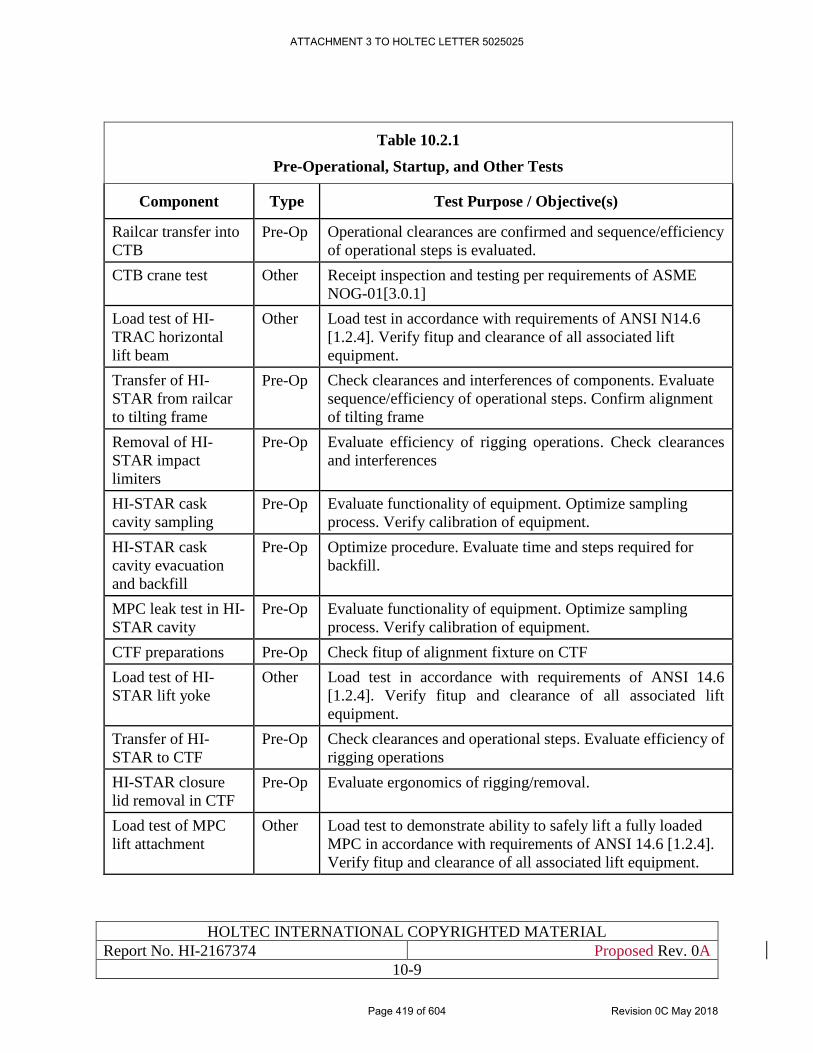
HOLTEC INTERNATIONAL COPYRIGHTED MATERIAL
Report No. HI-2167374 Proposed Rev. 0A
10-9
Table 10.2.1
Pre-Operational, Startup, and Other Tests
Component Type Test Purpose / Objective(s)
Railcar transfer into
CTB
Pre-Op Operational clearances are confirmed and sequence/efficiency
of operational steps is evaluated.
CTB crane test Other Receipt inspection and testing per requirements of ASME
NOG-01[3.0.1]
Load test of HI-
TRAC horizontal
lift beam
Other Load test in accordance with requirements of ANSI N14.6
[1.2.4]. Verify fitup and clearance of all associated lift
equipment.
Transfer of HI-
STAR from railcar
to tilting frame
Pre-Op Check clearances and interferences of components. Evaluate
sequence/efficiency of operational steps. Confirm alignment
of tilting frame
Removal of HI-
STAR impact
limiters
Pre-Op Evaluate efficiency of rigging operations. Check clearances
and interferences
HI-STAR cask
cavity sampling
Pre-Op Evaluate functionality of equipment. Optimize sampling
process. Verify calibration of equipment.
HI-STAR cask
cavity evacuation
and backfill
Pre-Op Optimize procedure. Evaluate time and steps required for
backfill.
MPC leak test in HI-
STAR cavity
Pre-Op Evaluate functionality of equipment. Optimize sampling
process. Verify calibration of equipment.
CTF preparations Pre-Op Check fitup of alignment fixture on CTF
Load test of HI-
STAR lift yoke
Other Load test in accordance with requirements of ANSI 14.6
[1.2.4]. Verify fitup and clearance of all associated lift
equipment.
Transfer of HI-
STAR to CTF
Pre-Op Check clearances and operational steps. Evaluate efficiency of
rigging operations
HI-STAR closure
lid removal in CTF
Pre-Op Evaluate ergonomics of rigging/removal.
Load test of MPC
lift attachment
Other Load test to demonstrate ability to safely lift a fully loaded
MPC in accordance with requirements of ANSI 14.6 [1.2.4].
Verify fitup and clearance of all associated lift equipment.
ATTACHMENT 3 TO HOLTEC LETTER 5025025
Page 419 of 604 Revision 0C May 2018
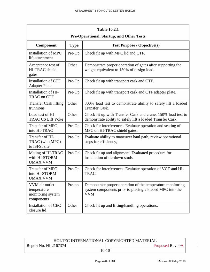
HOLTEC INTERNATIONAL COPYRIGHTED MATERIAL
Report No. HI-2167374 Proposed Rev. 0A
10-10
Table 10.2.1
Pre-Operational, Startup, and Other Tests
Component Type Test Purpose / Objective(s)
Installation of MPC
lift attachment
Pre-Op Check fit up with MPC lid and CTF.
Acceptance test of
HI-TRAC shield
gates
Other Demonstrate proper operation of gates after supporting the
weight equivalent to 150% of design load.
Installation of CTF
Adapter Plate
Pre-Op Check fit up with transport cask and CTF.
Installation of HI-
TRAC on CTF
Pre-Op Check fit up with transport cask and CTF adapter plate.
Transfer Cask lifting
trunnions
Other 300% load test to demonstrate ability to safely lift a loaded
Transfer Cask.
Load test of HI-
TRAC CS Lift Yoke
Other Check fit up with Transfer Cask and crane. 150% load test to
demonstrate ability to safely lift a loaded Transfer Cask.
Transfer of MPC
into HI-TRAC
Pre-Op Check for interferences. Evaluate operation and seating of
MPC on HI-TRAC shield gates.
Transfer of HI-
TRAC (with MPC)
to ISFSI site
Pre-Op Evaluate ability to maneuver haul path, review operational
steps for efficiency,
Mating of HI-TRAC
with HI-STORM
UMAX VVM
Pre-Op Check fit up and alignment. Evaluated procedure for
installation of tie-down studs.
Transfer of MPC
into HI-STORM
UMAX VVM
Pre-Op Check for interferences. Evaluate operation of VCT and HI-
TRAC.
VVM air outlet
temperature
monitoring system
components
Pre-op Demonstrate proper operation of the temperature monitoring
system components prior to placing a loaded MPC into the
VVM
Installation of CEC
closure lid
Other Check fit up and lifting/handling operations.
ATTACHMENT 3 TO HOLTEC LETTER 5025025
Page 420 of 604 Revision 0C May 2018
HOLTEC INTERNATIONAL COPYRIGHTED MATERIAL
Report No. HI-2167374 Proposed Rev. 0A
10-11
10.3 NORMAL OPERATION
This section describes the administrative controls and conduct of operations associated with
activities considered important to safety. Also described in this section is the management system
for maintaining records related to the operation of the ISFSI.
10.3.1 Procedures
Activities affecting quality are accomplished in accordance with approved and documented
instructions, procedures, or drawings. Written procedures will be used for site operations,
maintenance, and testing activities that are quality-related as defined in the Holtec Quality
Assurance Manual [12.0.1]. Procedures will be used to implement the Fire Protection Program and
training and certification of personnel. The review and approval process for procedures, and
changes thereto, will be procedurally controlled. The Site Manager or his designee will approve
procedures and changes prior to implementation. Temporary changes to procedures are allowed
if the intent of the existing procedure is not altered and the change is approved by the Site Manager
or his/her designee.
Site procedures will require that any changes to facilities, equipment or procedures will be
reviewed for safety impact to ensure that the proposed change does not require prior NRC approval
pursuant to 10CFR72.48.
10.3.2 Records
Administrative procedures will be established and maintained to ensure quality assurance records
are identifiable and retrievable. In addition to quality assurance records, the following records will
also be maintained in accordance with 10CFR72.174:
1. Operating records, including maintenance and modifications.
2. Records of off-normal occurrences.
3. Events associated with radioactive releases.
4. Environmental survey records.
5. Personnel Training and Qualification Records.
6. Records of ISFSI design changes made pursuant to 10CFR72.48.
7. Records showing the receipt, inventory (including location), disposal, acquisition, and
transfer of spent fuel and related nuclear material as required by 10CFR72.72(a).
8. Records of material control and inventory procedures to account for material in storage as
required by 10CFR72.72.
Records of site procedure changes, and tests and experiments, conducted pursuant to 10CFR72.48
will be maintained in accordance with 10CFR72.48. Storage of the above records will be in
accordance with the requirements of the Holtec Quality Assurance Manual [12.0.1].
Security records, including security training and qualification records, will be maintained in
accordance with the HI-STORE Site Security Plan [3.1.1].
ATTACHMENT 3 TO HOLTEC LETTER 5025025
Page 421 of 604 Revision 0C May 2018
HOLTEC INTERNATIONAL COPYRIGHTED MATERIAL
Report No. HI-2167374 Proposed Rev. 0A
10-12
10.3.3 Conduct of Operations
The information presented in this section will be used to develop detailed operating procedures for
the receipt of MPC transport casks and the safe transfer of the MPCs to their storage location at
the HI-STORE site. In preparing the procedures, the user must consult the conditions of the
Technical Specifications, equipment-specific operating instructions, and the HI-STORE site’s
working procedures as well as the information in this chapter to ensure that the short-term
operations shall be carried out with utmost safety and ALARA.
The following generic criteria shall be used to determine whether the HI-STORE site operating
procedures developed pursuant to the guidance in this chapter are acceptable for use:
• All heavy load handling instructions are in keeping with the guidance in industry
standards and Holtec-provided instructions.
• The procedures are in conformance with this SAR and its Technical Specifications.
• The procedures are in conformance with the HI-STORM UMAX FSAR [1.0.6] and HI-
STORM FW System FSAR [1.3.7] where applicable.
• The operational steps are ALARA.
• The procedures contain provisions for documenting successful execution of all safety
significant steps for archival reference.
• Procedures contain provisions for classroom and hands-on training and for a Holtec-
approved personnel qualification process to ensure that all operations personnel are
adequately trained.
• The procedures are sufficiently detailed and articulated to enable craft labor to execute
them in literal compliance with their content.
Independent safety reviews will be performed and documented by qualified Independent Safety
Reviewers (ISR) prior the performance of any operations. The independent safety reviews shall
confirm that changes to the facility, changes to operating procedures, and the performance of tests
and experiments not described in the Safety Analysis Report are safe and do not require prior NRC
approval pursuant to 10CFR72.48.
10.3.3.1 Receipt and Inspection of Transportation Cask and Canister
The following operational steps are used to receive and inspect the transportation cask in the HI-
STORE CTB. The steps also include
1. The HI-STAR packaging is visually receipt inspected to verify that there are no outward
visual indications of impaired physical conditions except for superficial marks and dents.
Any issues are identified to site management. Any road dirt is washed off and any foreign
material is removed.
2. The HI-STAR transportation package is moved into the CTB building security trap, where
it is inspected by HI-STORE site security personnel to ensure no unauthorized devices
enter the CTB building.
ATTACHMENT 3 TO HOLTEC LETTER 5025025
Page 422 of 604 Revision 0C May 2018
HOLTEC INTERNATIONAL COPYRIGHTED MATERIAL
Report No. HI-2167374 Proposed Rev. 0A
10-13
3. The HI-STAR transportation package is moved into the CTB.
4. The personnel barrier, if used, is removed and the security seal installed on the top impact
limiter is inspected to verify there was no tampering and that it matches the corresponding
shipping documents.
5. The HI-STAR shipment personnel barrier and tie-downs are removed. The radial spacers
are removed from the top and bottom of the cask.
6. Radiological surveys are performed in accordance with 49CFR173.443 [10.3.1] and
10CFR20.1906 [7.4.1]. Any issues are identified to site management. If necessary, the
overpack is decontaminated as directed by site radiation protection. Appropriate
notifications are made as detailed in the surveillance requirements.
7. The HI-STAR is rigged and transferred to the tilt frame using the CTB building crane.
ALARA Warning:
Dose rates around the bottom end of the HI-STAR cask may be higher that other
locations around the cask. After the impact limiter is removed, the cask should be
upended promptly. Personnel should remain clear of the bottom of the unshielded
cask and exercise other appropriate ALARA controls.
8. The HI-STAR impact limiters are rigged and removed using the CTB crane and a second
visual inspection to verify that there are no outward visual indications of impaired physical
condition is performed.
9. The neutron shield relief devices are inspected to confirm that they are installed, intact, and
not covered by tape or any other covering.
10. As a safety precaution, the HI-STAR closure lid access port cover is removed and sampling
equipment is attached to test for the presence of Krypton-85. The sampling equipment
consists of a cover flange that allows remote opening of the closure lid port plug to ensure
there is no release of radioactive material. The cover flange and gas sample canister is
evacuated prior to opening the port plug to ensure the sample accurately reflects the cask
cavity contents. The cask cavity gas sample is handled in accordance with Radiation
Protection directions by qualified personnel. Testing is performed per pre-approved
procedure, using appropriately calibrated equipment that has been qualified for testing at
expected concentration limits, to confirm that the sample meets the acceptance criteria of
Table 10.3.3. In the unlikely event that the Krypton-85 concentration exceeds the
acceptance criteria, the canister transfer operations are terminated and site management is
informed for disposition.
ATTACHMENT 3 TO HOLTEC LETTER 5025025
Page 423 of 604 Revision 0C May 2018
HOLTEC INTERNATIONAL COPYRIGHTED MATERIAL
Report No. HI-2167374 Proposed Rev. 0A
10-14
Operational Limit:
Prior to performing evacuation, flushing, and leak testing of the MPC within the
HI-STAR cask, an evaluation based on the specific transportation cask conditions,
canister conditions (including heat load), and leak test conditions shall be performed
to establish a canister-specific time limit for all operations performed without
helium in the cask annulus. A previously performed bounding evaluation may also
be utilized. Process steps shall be stopped before reaching the thermal time limit,
and the helium backfill shall be re-established per the requirements of Table 10.3.4
before continuing.
11. The sampling equipment is removed, and the HI-STAR annulus space is evacuated and
flushed with nitrogen using the sampling equipment connector. This process may be
repeated several times, as determined by process experience and required by the approved
test procedure, to ensure residual helium is flushed from the annulus space. Refer to Table
10.3.4 for process pressure limits.
12. The mass spectrometer leak test apparatus is attached to the sampling equipment connector
and a leak test of the MPC is performed. Leakage rate testing is performed per procedures
written and approved in accordance with the requirements of ANSI N14.5-2014 [10.3.3].
All testing is performed by qualified personnel in accordance with the Holtec QA program.
The written and approved test procedures shall clearly define the test equipment
arrangement. Leakage rate testing procedures shall be approved by an ASNT Level III
specialist. The applicable recommended guidelines of SNT-TC-1A [10.3.2] shall be
considered as minimum requirements. Canister leakage test specifications are listed in
Table 10.3.2. If a canister leak is detected, the canister transfer operations are terminated
and site management is informed for disposition.
13. The CTF is inspected and prepared for receipt of the HI-STAR transportation cask.
14. The HI-STAR is upended, removed from the tilting frame and transferred to the CTF using
a lift yoke attached to the cask trunnions and the CTB crane.
10.3.3.2 Transfer of Canister from Transportation Cask to HI-TRAC
1. Using the CTB crane, the HI-TRAC alignment plate is installed on the CTF over the HI-
TRAC cask.
2. The HI-STAR closure lid bolts are removed and the closure lid is removed using the CTB
crane.
ATTACHMENT 3 TO HOLTEC LETTER 5025025
Page 424 of 604 Revision 0C May 2018
HOLTEC INTERNATIONAL COPYRIGHTED MATERIAL
Report No. HI-2167374 Proposed Rev. 0A
10-15
ALARA Warning:
Personnel should remain clear of the open end of the unshielded cask and exercise other
appropriate ALARA controls. Dose rates around open end of the HI-STAR cask may
be higher that other locations around the cask. Temporary shielding may be installed to
reduce worker dose ALARA.
3. A cask seal surface protector is installed on the closure lid sealing surface to protect it from
damage.
4. The MPC lifting attachment is connected to the threaded holes on the MPC closure lid. The
lifting attachment bolts are tightened hand-tight.
5. Using the CTB crane, the HI-TRAC is placed on the HI-TRAC alignment plate with the
shield gates open. The CTF studs are secured to the HI-TRAC and the nuts are tightened
wrench- tight.
6. The MPC lifting extension is attached to the CTB crane, lowered through the HI-TRAC
body, and engaged with the MPC lift attachment.
7. Using the CTB crane, the MPC is lifted into the HI-TRAC.
8. The HI-TRAC shield gates are closed, and the MPC is lowered to rest on the gates.
9. The MPC lifting extension is disconnected and removed using the CTB crane.
10. The HI-TRAC lift yoke is connected to CTB crane and the HI-TRAC lift trunnions.
11. The CTF stud nuts are removed.
12. The HI-TRAC is lifted using the CTB crane and placed in a location of the CTB floor that
is accessible to the VCT.
10.3.3.4 Preparation of VVM for Receipt of MPC
1. Prior to receipt of the MPC, install or confirm installation of the appropriate divider shell
in the appropriate VVM for the planned MPC. Installation and verification shall be
procedurally controlled and reviewed to ensure correct VVM component designs are
specified so that licensing requirements are met.
2. If not already removed, remove the closure lid using a crane or other equivalent lifting
device.
3. Install the HI-TRAC restraint studs in the VVM threaded anchors.
Operations Note:
In addition to securing the HI-TRAC to the VVM, the restraint studs also provide
alignment while positioning the HI-TRAC on the VVM.
ATTACHMENT 3 TO HOLTEC LETTER 5025025
Page 425 of 604 Revision 0C May 2018
HOLTEC INTERNATIONAL COPYRIGHTED MATERIAL
Report No. HI-2167374 Proposed Rev. 0A
10-16
10.3.3.5 Placement of Canisters in the CEC
1. Position the VCT over the loaded HI-TRAC.
13. Attach the HI-TRAC CS lift links to the HI-TRAC and lift the HI-TRAC several inches
off the ground, as needed for transport to the ISFSI.
Operations Note:
If required for transport of the loaded HI-TRAC to the designated VVM, the outlet air
vent extensions for previously loaded or unloaded VVMs may be temporarily removed
(if installed) to minimize the required lift height for the HI-TRAC. For previously loaded
VVMs, the outlet air vent extensions shall be expeditiously re-installed to restore the
VVMs to its normal condition of storage.
2. Using the VCT, transport the loaded HI-TRAC to the ISFSI and place the loaded HI-TRAC
on the VVM, using the HI-TRAC restraint studs (previously installed) to ensure proper
alignment.
14. Disconnect the HI-TRAC CS lift links from the HI-TRAC and rig the MPC lifting
attachment to the VCT using the MPC lifting extension.
3. Raise the MPC slightly to remove the weight of the MPC from the HI-TRAC Shield Gate.
ALARA Warning:
Temporary shielding may be used to reduce personnel dose during MPC transfer
operations. If used, temporary shielding must not restrict air flow into CEC inlet vent
openings. If ALARA considerations dictate that temporary shielding not be used,
personnel must remain clear of the immediate area around the HI-TRAC Shield Gates
during MPC downloading.
4. Open the HI-TRAC Shield Gate. At the user’s discretion, install temporary shielding to
cover the potential streaming paths around the HI-TRAC Shield Gates.
5. Lower the MPC into the VVM.
6. Verify that the MPC is fully seated in the VVM.
Caution:
Operations steps that occur with the MPC in the VVM with the HI-TRAC Shield
Gate closed must be performed in an expeditious manner to avoid excessive heating
of the MPC and fuel. The Mating Device must be removed or the drawer opened
to establish air cooling within the time limits described in Section 4.5. In the event
of equipment malfunction that results in the blockage of air flow, corrective actions
must occur within the time limits of the 100% blocked duct accident condition.
7. Disconnect the MPC lifting attachment from the MPC and remove using the lifting
ATTACHMENT 3 TO HOLTEC LETTER 5025025
Page 426 of 604 Revision 0C May 2018
HOLTEC INTERNATIONAL COPYRIGHTED MATERIAL
Report No. HI-2167374 Proposed Rev. 0A
10-17
extension and the VCT.
8. Remove any temporary shielding and close the HI-TRAC Shield Gates.
ALARA Warning:
Personnel should remain clear (to the maximum extent practicable) of the VVM annulus
when HI-TRAC is being removed to comply with ALARA requirements.
9. Remove the HI-TRAC transfer cask from the top of the VVM.
10. Install plugs in the empty MPC bolt holes.
Guidance:
The VVM closure lid shall be preferably kept less than 2 feet above the top surface of
the VVM while over the MPC. This lift limit action is purely a defense-in-depth measure
because the Closure Lid cannot fall and impact the MPC because of geometric
constraints.
11. Install the VVM closure lid. Check that the rigging (in its specific configuration) is rated
to lift the load (rated to lift two times the load per NUREG 0612).
12. Remove the VVM closure lid rigging equipment and re-install the outlet vent cover (if
previously removed).
13. Install the VVM temperature monitoring elements (if used).
14. Ensure records showing the receipt, inventory (including location), disposal, acquisition,
and transfer of the canister, as required by 10CFR72.72(a), are complete.
10.3.3.6 Removal of Canisters from the CEC
If necessary, canisters are recovered from the HI-STORM UMAX VVM and returned to the
transport cask in accordance with the steps described in this Section, except that the order is
basically reversed.
10.3.4 Maintenance Program for the HI-STORM UMAX VVM Systems
An ongoing maintenance program shall be defined and incorporated into the HI-STORM UMAX
system Operations and Maintenance Manual for the HI-STORE CIS facility. This document shall
delineate the detailed inspections, testing, and parts replacement necessary to ensure continued
structural, thermal performance, and radiological safety in accordance with 10CFR72 regulations,
the conditions in the Technical Specifications, and the design requirements and criteria contained
in this SAR.
The HI-STORM UMAX system is totally passive by design and requires minimal preventive
maintenance to ensure that it will render its intended design functions satisfactorily. Periodic
surveillance (via temperature monitoring or visual or camera-aided inspection of air passages) is
required to ensure that the air passage in the VVM is not blocked. Preventive or remedial painting
ATTACHMENT 3 TO HOLTEC LETTER 5025025
Page 427 of 604 Revision 0C May 2018
HOLTEC INTERNATIONAL COPYRIGHTED MATERIAL
Report No. HI-2167374 Proposed Rev. 0A
10-18
of the exposed steel surfaces as part of the user’s preventive maintenance program is recommended
to mitigate corrosion.
In-service inspection for long-term interior and below-grade degradation shall be performed by
visual inspection of accessible areas of the HI-STORM UMAX VVM. The frequency of this visual
in-service inspection should be in performed in accordance with Table 10.3.1. Acceptance criteria
for visual inspections shall be based on confirmation that the components continue to meet the
licensing basis design requirements.
Additional in-service inspection activities will include more thorough inspections for foreign
material accumulation, corrosion (CEC wall thinning) and insulation degradation. A VVM with a
loaded MPC may be inspected using remote devices such as a boroscope. The oldest VVM or
VVM considered to be most vulnerable to corrosion degradation shall be selected for inspection.
Among the QA commitments are performance of maintenance by trained personnel by written
procedures and written documentation of the maintenance work performed and of the results
obtained. Table 10.3.1 provides a listing of the minimum maintenance activities on the HI-STORM
UMAX VVM.
In summary, the HI-STORM UMAX System is totally passive by design: There are no active
components or monitoring systems required to assure the performance of its safety functions. As
a result, only minimal maintenance will be required over its lifetime, and this maintenance would
primarily result from the effects of weather. Typical of such maintenance would be the
reapplication of corrosion inhibiting materials on accessible external surfaces. Visual inspection
of the vent screens is required to ensure the air flow passages are free from obstruction
Maintenance activities shall be performed under Holtec’s NRC-approved quality assurance
program. Maintenance activities shall be administratively controlled and the results documented.
10.3.4.1 Structural Capacity Verification
Prior to each MPC loading, a visual examination in accordance with a written procedure shall be
required of the Closure Lid lift lugs and the HI-TRAC trunnions, bottom lid bolts, and bolt holes.
The examination shall inspect for indications of overstress such as cracks, deformation, wear
marks, corrosion, etc. Repairs in accordance with written and approved procedures shall be
required if an unacceptable condition is identified.
10.3.4.2 Shielding Capacity
The gamma and neutron shielding materials in HI-TRAC CS are not subject to measurable
degradation over time or as a result of usage. The radiation shielding capacity of the HI-STORM
UMAX System is expected to remain undiminished over time. Therefore, unless the VVM is
subjected to an extreme environmental event that imparts stresses or temperatures beyond-the-
design-basis limits for the system (i.e., prolonged fire or impact from a beyond-the-design basis
large energetic projectile) with the plausible potential to degrade the shielding effectiveness of the
VVM, no shielding effectiveness tests beyond that required by the HI-STORE’s Radiation
Protection Program are required over the life of the AFR facility.
ATTACHMENT 3 TO HOLTEC LETTER 5025025
Page 428 of 604 Revision 0C May 2018
HOLTEC INTERNATIONAL COPYRIGHTED MATERIAL
Report No. HI-2167374 Proposed Rev. 0A
10-19
Radiation monitoring of the ISFSI in accordance with 10CFR72.104(c) will provide ongoing
evidence and confirmation of shielding integrity and performance. If increased radiation doses are
indicated by the facility monitoring program, additional surveys of the ISFSI shall be performed
to determine the cause of the increased dose rates.
10.3.4.3 Thermal Capacity
In order to assure that the HI-STORM UMAX System continues to provide effective thermal
performance during storage operations, surveillance of the air vents (or alternatively, by
temperature monitoring) shall be performed in accordance with written procedures.
10.3.5 Maintenance Program for the Canister
The canister is an all-welded stainless steel pressure vessel that does not require an in-service
maintenance unless a disruptive occurrence such as deposition of flood-borne foreign materials on
the canister’s surface occurs. Because submergence from flood has been rules out as a credible
occurrence at the HI-STORE ISFSI, no routine in-service maintenance activity on the stored
canister is expected. The Aging Management Program described in Chapter 18, however, will
require monitoring and inspection activities, and possibly remedial actions, if so determined.
10.3.6 Maintenance Programs for ITS Lifting and Handling Equipment, Including VCT
Maintenance, inspection and testing of lifting equipment designed to ANSI 14.6 [1.2.4] shall per
the requirements of ANSI 14.6. Equipment designed the requirements of ASME Section III,
Subsection NF [4.5.1] shall be functionally tested prior to initial use and visually inspected for any
degradation or damage prior to each cask transfer.
10.3.7 Maintenance Programs for ITS Crane Systems
Maintenance, inspection and testing of crane systems designed to ASME NOG-1 [3.0.1] shall per
the requirements of ASME NOG-1.
10.3.8 Maintenance Program for HI-STAR 190 Cask
The maintenance program for the HI-STAR 190 Cask shall be as specified in the HI-STAR 190
SAR [1.3.6].
ATTACHMENT 3 TO HOLTEC LETTER 5025025
Page 429 of 604 Revision 0C May 2018
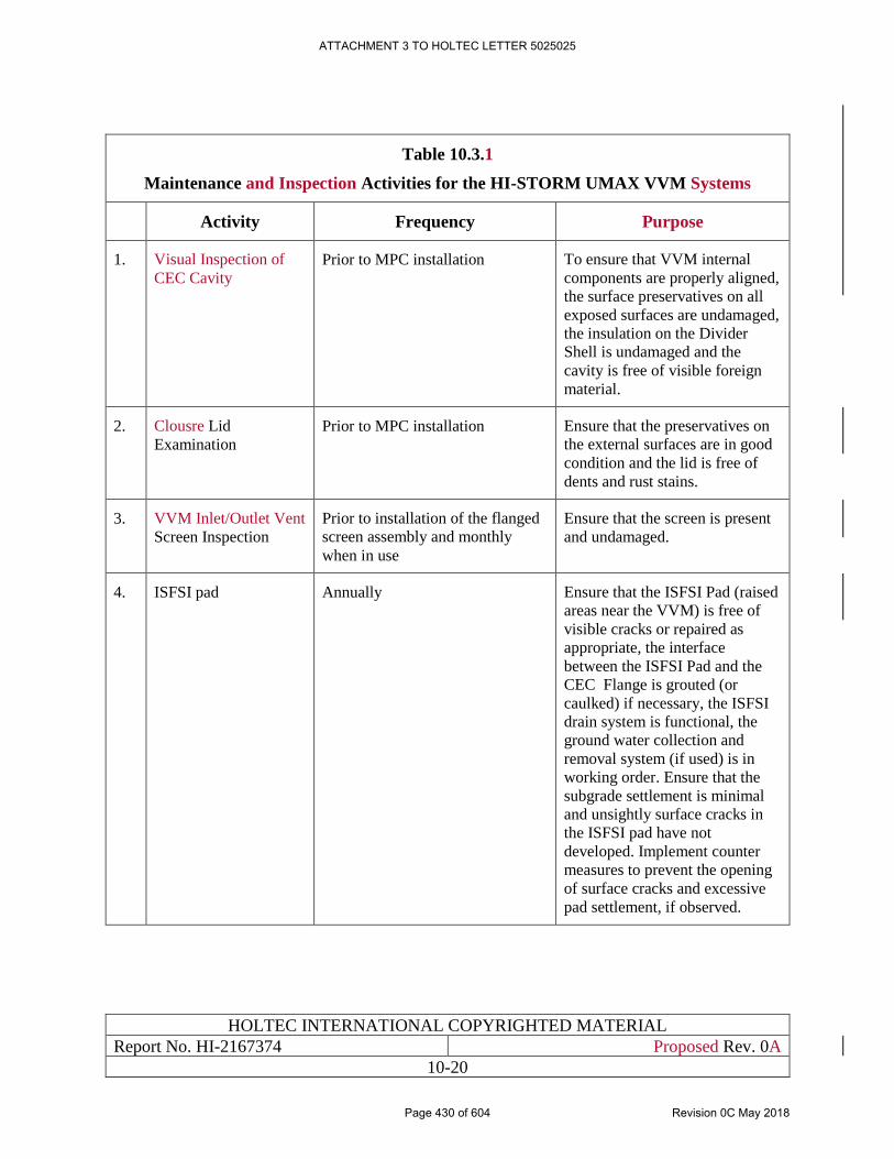
HOLTEC INTERNATIONAL COPYRIGHTED MATERIAL
Report No. HI-2167374 Proposed Rev. 0A
10-20
Table 10.3.1
Maintenance and Inspection Activities for the HI-STORM UMAX VVM Systems
Activity Frequency Purpose
1. Visual Inspection of
CEC Cavity
Prior to MPC installation To ensure that VVM internal
components are properly aligned,
the surface preservatives on all
exposed surfaces are undamaged,
the insulation on the Divider
Shell is undamaged and the
cavity is free of visible foreign
material.
2. Clousre Lid
Examination
Prior to MPC installation Ensure that the preservatives on
the external surfaces are in good
condition and the lid is free of
dents and rust stains.
3. VVM Inlet/Outlet Vent
Screen Inspection
Prior to installation of the flanged
screen assembly and monthly
when in use
Ensure that the screen is present
and undamaged.
4. ISFSI pad Annually Ensure that the ISFSI Pad (raised
areas near the VVM) is free of
visible cracks or repaired as
appropriate, the interface
between the ISFSI Pad and the
CEC Flange is grouted (or
caulked) if necessary, the ISFSI
drain system is functional, the
ground water collection and
removal system (if used) is in
working order. Ensure that the
subgrade settlement is minimal
and unsightly surface cracks in
the ISFSI pad have not
developed. Implement counter
measures to prevent the opening
of surface cracks and excessive
pad settlement, if observed.
ATTACHMENT 3 TO HOLTEC LETTER 5025025
Page 430 of 604 Revision 0C May 2018
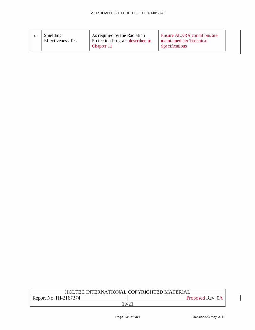
HOLTEC INTERNATIONAL COPYRIGHTED MATERIAL
Report No. HI-2167374 Proposed Rev. 0A
10-21
5. Shielding
Effectiveness Test
As required by the Radiation
Protection Program described in
Chapter 11
Ensure ALARA conditions are
maintained per Technical
Specifications
ATTACHMENT 3 TO HOLTEC LETTER 5025025
Page 431 of 604 Revision 0C May 2018
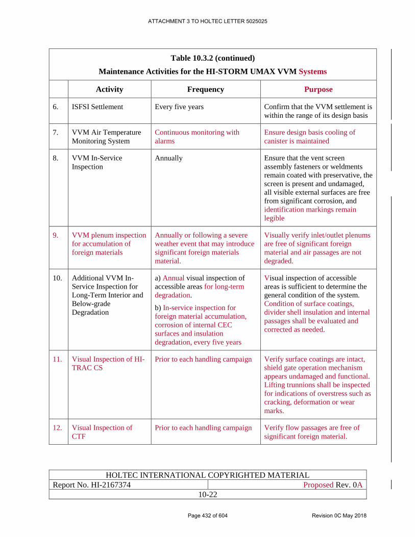
HOLTEC INTERNATIONAL COPYRIGHTED MATERIAL
Report No. HI-2167374 Proposed Rev. 0A
10-22
Table 10.3.2 (continued)
Maintenance Activities for the HI-STORM UMAX VVM Systems
Activity Frequency Purpose
6. ISFSI Settlement Every five years Confirm that the VVM settlement is
within the range of its design basis
7. VVM Air Temperature
Monitoring System
Continuous monitoring with
alarms
Ensure design basis cooling of
canister is maintained
8. VVM In-Service
Inspection
Annually Ensure that the vent screen
assembly fasteners or weldments
remain coated with preservative, the
screen is present and undamaged,
all visible external surfaces are free
from significant corrosion, and
identification markings remain
legible
9. VVM plenum inspection
for accumulation of
foreign materials
Annually or following a severe
weather event that may introduce
significant foreign materials
material.
Visually verify inlet/outlet plenums
are free of significant foreign
material and air passages are not
degraded.
10. Additional VVM In-
Service Inspection for
Long-Term Interior and
Below-grade
Degradation
a) Annual visual inspection of
accessible areas for long-term
degradation.
b) In-service inspection for
foreign material accumulation,
corrosion of internal CEC
surfaces and insulation
degradation, every five years
Visual inspection of accessible
areas is sufficient to determine the
general condition of the system.
Condition of surface coatings,
divider shell insulation and internal
passages shall be evaluated and
corrected as needed.
11. Visual Inspection of HI-
TRAC CS
Prior to each handling campaign Verify surface coatings are intact,
shield gate operation mechanism
appears undamaged and functional.
Lifting trunnions shall be inspected
for indications of overstress such as
cracking, deformation or wear
marks.
12. Visual Inspection of
CTF
Prior to each handling campaign Verify flow passages are free of
significant foreign material.
ATTACHMENT 3 TO HOLTEC LETTER 5025025
Page 432 of 604 Revision 0C May 2018
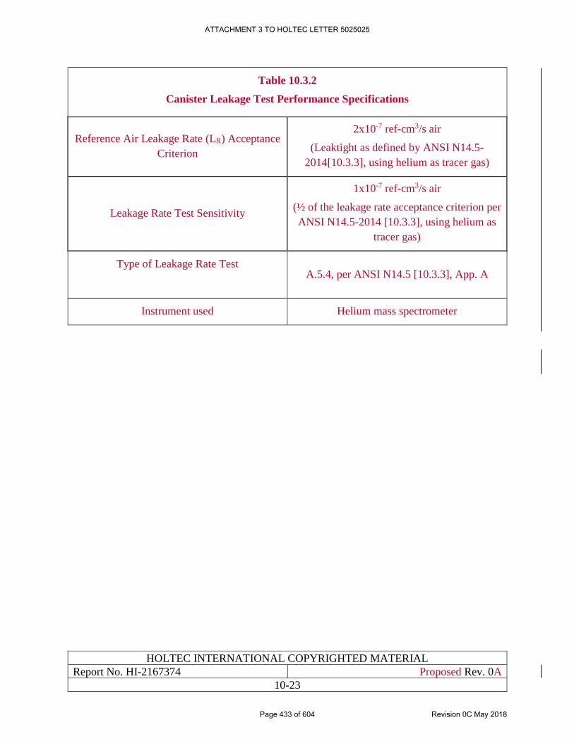
HOLTEC INTERNATIONAL COPYRIGHTED MATERIAL
Report No. HI-2167374 Proposed Rev. 0A
10-23
Table 10.3.2
Canister Leakage Test Performance Specifications
Reference Air Leakage Rate (LR) Acceptance
Criterion
2x10⁻⁷ ref-cm3/s air
(Leaktight as defined by ANSI N14.5-
2014[10.3.3], using helium as tracer gas)
Leakage Rate Test Sensitivity
1x10⁻⁷ ref-cm3/s air
(½ of the leakage rate acceptance criterion per
ANSI N14.5-2014 [10.3.3], using helium as
tracer gas)
Type of Leakage Rate Test
A.5.4, per ANSI N14.5 [10.3.3], App. A
Instrument used Helium mass spectrometer
ATTACHMENT 3 TO HOLTEC LETTER 5025025
Page 433 of 604 Revision 0C May 2018
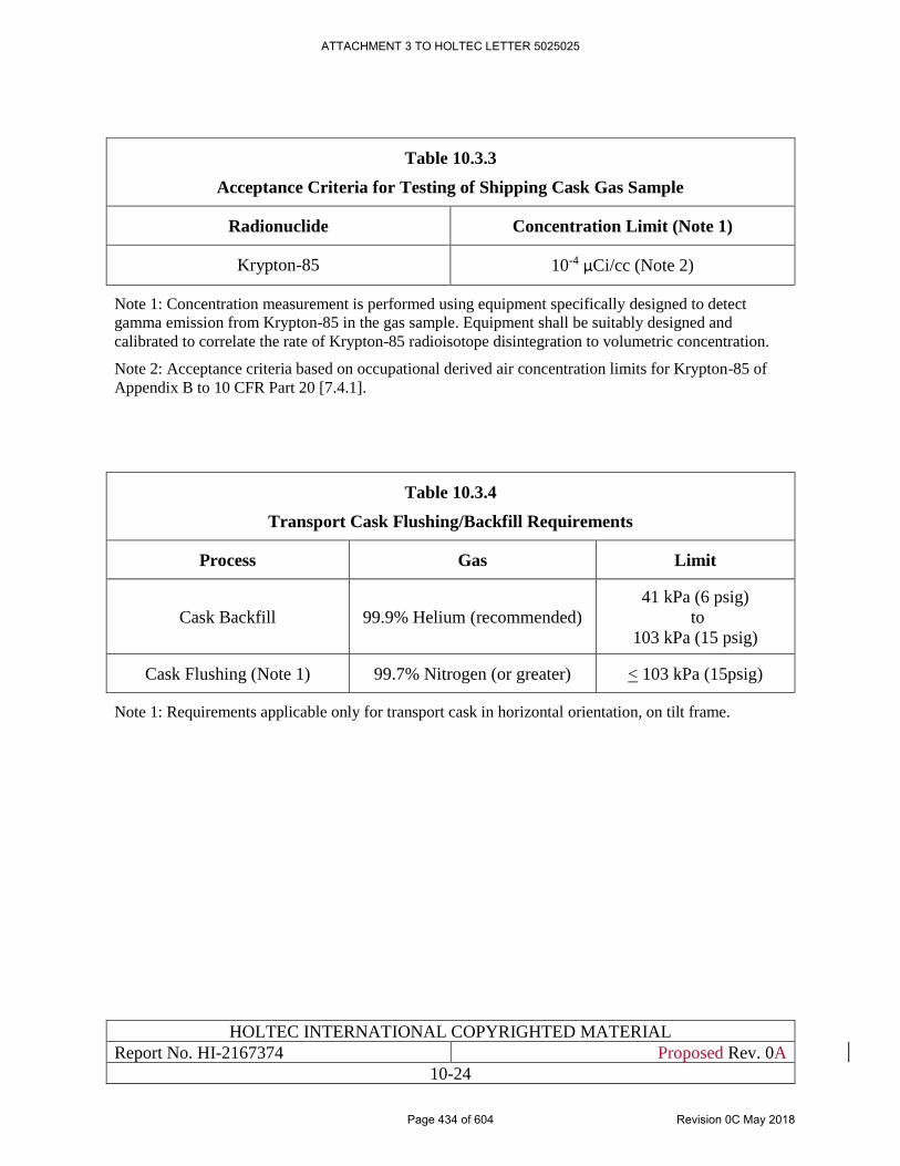
HOLTEC INTERNATIONAL COPYRIGHTED MATERIAL
Report No. HI-2167374 Proposed Rev. 0A
10-24
Table 10.3.3
Acceptance Criteria for Testing of Shipping Cask Gas Sample
Radionuclide Concentration Limit (Note 1)
Krypton-85 10-4 μCi/cc (Note 2)
Note 1: Concentration measurement is performed using equipment specifically designed to detect
gamma emission from Krypton-85 in the gas sample. Equipment shall be suitably designed and
calibrated to correlate the rate of Krypton-85 radioisotope disintegration to volumetric concentration.
Note 2: Acceptance criteria based on occupational derived air concentration limits for Krypton-85 of
Appendix B to 10 CFR Part 20 [7.4.1].
Table 10.3.4
Transport Cask Flushing/Backfill Requirements
Process Gas Limit
Cask Backfill 99.9% Helium (recommended)
41 kPa (6 psig)
to
103 kPa (15 psig)
Cask Flushing (Note 1) 99.7% Nitrogen (or greater) < 103 kPa (15psig)
Note 1: Requirements applicable only for transport cask in horizontal orientation, on tilt frame.
ATTACHMENT 3 TO HOLTEC LETTER 5025025
Page 434 of 604 Revision 0C May 2018
HOLTEC INTERNATIONAL COPYRIGHTED MATERIAL
Report No. HI-2167374 Proposed Rev. 0A
10-25
10.4 PERSONNEL SELECTION, TRAINING, AND CERTIFICATION
10.4.1 Personnel Organization
The personnel organization is shown in the organization charts in Figures 10.4.1 and 10.4.2.
10.4.2 Selection and Training of Operating Personnel
The main objective of the training program is to provide personnel with the specialized training
necessary to operate and maintain the site in a safe manner.
Individuals requiring unescorted access to the site will receive training in the following areas:
Radiation Protection, Security, Radiological Emergency Plan, Quality Assurance, Fire Protection,
Chemical Safety, OSHA compliance, and the Policy statement on worker responsibility for safe
operation of the ISFSI. Individuals requiring continued unescorted access will receive refresher
training on these topics annually.
Individuals performing quality-related activities in support of the site will receive training on the
QA Program, QA policies, and if applicable, site procedures and organization as necessary to
ensure that suitable proficiency is maintained.
Operation of equipment and controls that are identified as important to safety for the ISFSI shall
be limited to personnel who are trained and certified in accordance with the HI-STORE Specialist
Training Program [10.1.1] or personnel who are under the direct visual supervision of a person
who is trained and certified in accordance with the HI-STORE Specialist Training Program
[10.1.1].
On-site workers will receive radiation protection training commensurate with their responsibilities
in accordance with 10 CFR 19, “Notices, Instructions and Reports to Workers: Inspection and
Investigations.” [11.1.1]
Records will be maintained on the status of trained personnel, training of new employees, and
refresher training of present personnel.
10.4.3 Selection and Training of Security Guards
Security training will be provided in accordance with the training and qualification requirements
outlined in the HI-STORE Site Security Plan [3.1.1].
10.4.4 Selection and Training of Radiation Protection Technicians
Radiation Protection Technicians will be trained and certified in accordance with the HI-STORE
Radiation Protection Technician Training Program. The main objective of the training program is
to provide personnel with the specialized training necessary to implement the procedures
associated with the Radiation Protection Program. Radiation Protection Technicians will receive
training in the use and calibration of radiation survey equipment, RWP generation and
implementation, ALARA principles, verifying proper packaging of radioactive material, and
proper response in the event of an emergency in accordance with the Radiological Emergency
Plan.
ATTACHMENT 3 TO HOLTEC LETTER 5025025
Page 435 of 604 Revision 0C May 2018
HOLTEC INTERNATIONAL COPYRIGHTED MATERIAL
Report No. HI-2167374 Proposed Rev. 0A
10-26
In addition, Radiation Protection Technicians will receive training in the following areas: Security,
Quality Assurance, Fire Protection, Chemical Safety, OSHA compliance, and the Policy statement
on worker responsibility for safe operation of the ISFSI. Individuals requiring continued
unescorted access will receive refresher training on these topics annually.
Records will be maintained on the status of trained personnel, training of new employees, and
refresher training of present personnel.
ATTACHMENT 3 TO HOLTEC LETTER 5025025
Page 436 of 604 Revision 0C May 2018
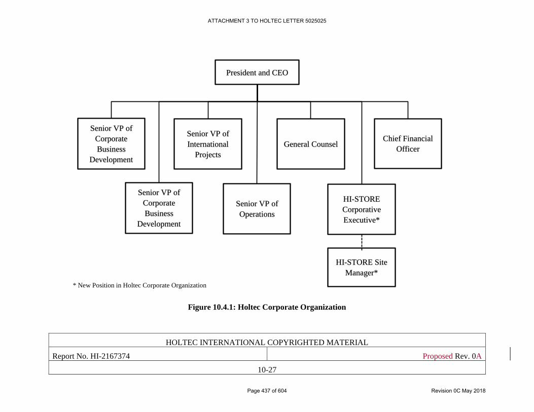
HOLTEC INTERNATIONAL COPYRIGHTED MATERIAL
Report No. HI-2167374 Proposed Rev. 0A
10-27
Figure 10.4.1: Holtec Corporate Organization
President and CEO
Site Manager
Senior VP of
Corporate
Business
Development
Senior VP of
International
Projects
Senior VP of
Corporate
Business
Development
Senior VP of
Operations
General Counsel Chief Financial
Officer
HI-STORE
Corporative
Executive*
* New Position in Holtec Corporate Organization
HI-STORE Site
Manager*
ATTACHMENT 3 TO HOLTEC LETTER 5025025
Page 437 of 604 Revision 0C May 2018
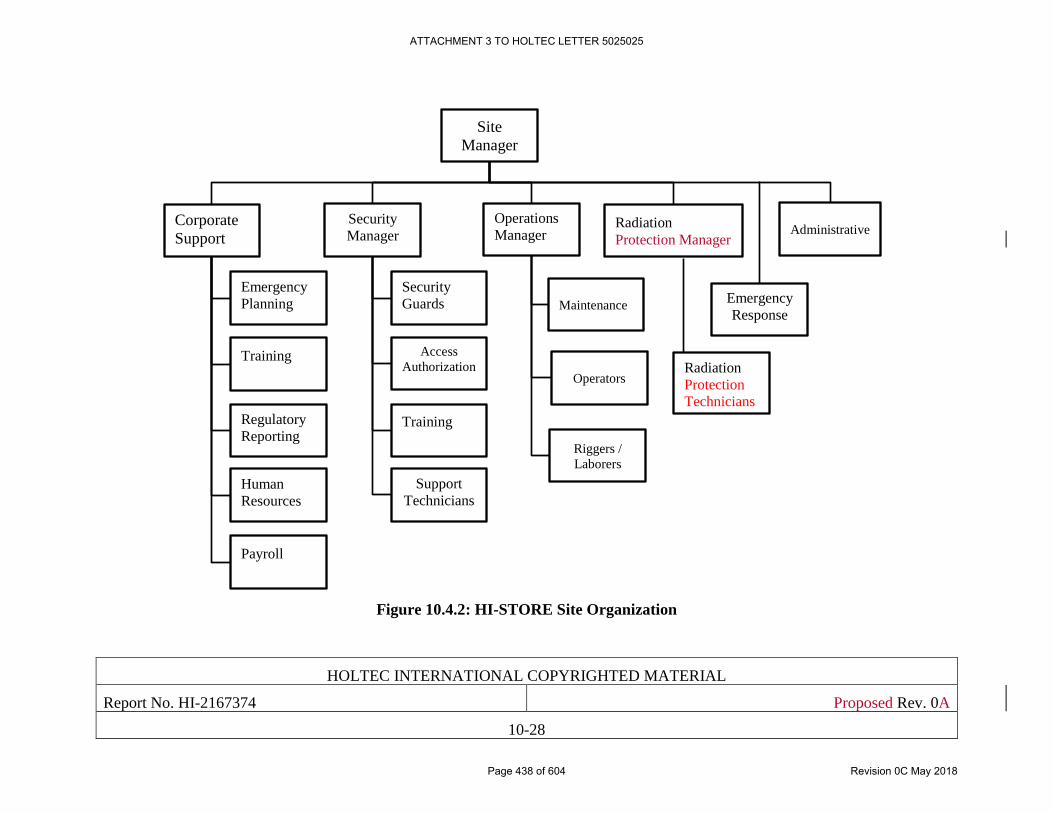
HOLTEC INTERNATIONAL COPYRIGHTED MATERIAL
Report No. HI-2167374 Proposed Rev. 0A
10-28
Figure 10.4.2: HI-STORE Site Organization
Site
Manager
Corporate
Support
Training
Human
Resources
Regulatory
Reporting
Emergency
Planning
Payroll
Security
Manager
Access
Authorization
Support
Technicians
Training
Security
Guards
Operations
Manager
Emergency
Response
Operators
Maintenance
Riggers /
Laborers
Administrative Radiation
Protection Manager
Radiation
Protection
Technicians
Safety
ATTACHMENT 3 TO HOLTEC LETTER 5025025
Page 438 of 604 Revision 0C May 2018
HOLTEC INTERNATIONAL COPYRIGHTED MATERIAL
Report No. HI-2167374 Proposed Rev. 0A
10-29
10.5 EMERGENCY PLANNING
The Holtec CISF Emergency Response Plan [10.5.1] evaluates and describes the necessary and
sufficient emergency response capabilities for managing all reasonably anticipated emergency
conditions associated with the operation of the HI-STORE facility. The plan meets all
requirements of 10CFR72.32(a).
ATTACHMENT 3 TO HOLTEC LETTER 5025025
Page 439 of 604 Revision 0C May 2018
HOLTEC INTERNATIONAL COPYRIGHTED MATERIAL
Report No. HI-2167374 Proposed Rev. 0A
10-30
10.6 PHYSICAL SECURITY AND SAFEGUARDS CONTINGENCY
PLANS
The HI-STORE Site Security Plan [3.1.1] contains a detailed plan for security measures for
physical protection of the site. In addition, this plan contains contingencies for responding to
threats and potential radiological sabotage. This plan complies with the requirements of 10CFR72,
Subpart H, “Physical Protection.”
ATTACHMENT 3 TO HOLTEC LETTER 5025025
Page 440 of 604 Revision 0C May 2018
HOLTEC INTERNATIONAL COPYRIGHTED MATERIAL
Report No. HI-2167374 Proposed Rev. 0A
10-31
10.7 RADIATION PROTECTION PLAN
Chapter 11 contains a detailed plan for radiation protection measures for the site. This plan
complies with the requirements of 10CFR72, Subpart H, “Physical Protection.” A Radiation
Protection Program is implemented at the CIS Facility in accordance with requirements of
10CFR72.126, 10CFR20.1101, and 10CFR19.12 [1.0.5], [7.4.1], and [11.1.1].
The CIS Facility is committed to a strong ALARA program. The ALARA program follows the
guidelines of Regulatory Guides 8.8 [11.1.2] and 8.10 [11.1.3] and the requirements of 10 CFR 20
[7.4.1].
ATTACHMENT 3 TO HOLTEC LETTER 5025025
Page 441 of 604 Revision 0C May 2018
HOLTEC INTERNATIONAL COPYRIGHTED MATERIAL
Report No. HI-2167374 Proposed Rev. 0A
10-32
10.8 SUMMARY
The conduct of operations described in this chapter fulfills the requirements of NUREG-1567
[1.0.3], Section 10, by providing the following information:
1 A plan for conduct of operations at the HI-STORE CIS site in compliance with
10CFR72.24(h).
2 Detailed description of the HI-STORM UMAX storage system operations which, based on
successful previous experience, is concluded to be largely demonstrated and in compliance
with 10CFR72.24(i).
3 Detailed description of the program covering preoperational testing and initial operations,
in compliance with 10CFR72.24(p).
4 The provision of acceptable technical qualifications, including training and experience, for
personnel who will be engaged in the proposed activities, in compliance with
10CFR72.28(a).
5 A description of a personnel training program to comply with 10CFR72,Subpart I.
6 A description of the operating organization, delegations of responsibility and authority,
and the minimum skills and experience qualifications relevant to the various levels of
responsibility and authority, in compliance with 10CFR72.28(c).
7 A commitment to maintain an adequate complement of trained and certified installation
personnel before receipt of spent fuel or high-level radioactive waste for storage, in
compliance with 10CFR72.28(d).
8 Assurance of qualification by reason of training and experience to conduct the operations
covered by the regulations in 10 CFR 72, in compliance with 10CFR72.40(a)(4).
9 Assurance with regard to the management, organization, and planning for preoperational
testing and initial operations that the activities authorized by the license can be conducted
without endangering the health and safety of the public, in compliance with
10CFR72.40(a)(13).
ATTACHMENT 3 TO HOLTEC LETTER 5025025
Page 442 of 604 Revision 0C May 2018
HOLTEC INTERNATIONAL COPYRIGHTED MATERIAL
Report No.: HI-2167374 Proposed Rev. 0A
11-1
CHAPTER 11: RADIATION PROTECTION EVALUATION
11.0 INTRODUCTION
11.0.1 Ensuring Occupational Radiation Exposures are As Low As is Reasonably
Achievable
The objective for the Centralized Interim Storage (CIS) Facility Radiation Protection Program is
to keep radiation exposures to facility workers and the general public as low as is reasonably
achievable (ALARA). Subsection 11.1.1 describes the policy and procedures that ensure that
ALARA occupational exposures are achieved. Subsection 11.1.2 describes the ALARA design
considerations and Subsection 11.1.3, the ALARA operational considerations.
The HI-STORE CIS Facility utilizes the HI-STORM UMAX storage system (Docket #72-1040)
[1.0.6 ], and only canisters approved for that system and listed in Table 1.0.3 are permitted for
storage in the facility. Therefore, the principal radiation protection evaluation is directly taken
from the HI-STORM UMAX FSAR, and is incorporated by reference. Table 11.0.1 lists all
sections from the HI-STORM UMAX FSAR that are incorporated by reference, together with a
technical justification. However, some additional radiation protection evaluation that is different
from that in the HI-STORM UMAX FSAR is required specifically for the HI-STORE CIS Facility,
due to site-specific considerations. These additional radiation protection evaluations are clearly
identified in the following sections.
All references are in placed within square brackets in this report and are compiled in Chapter
19 (References)
ATTACHMENT 3 TO HOLTEC LETTER 5025025
Page 443 of 604 Revision 0C May 2018
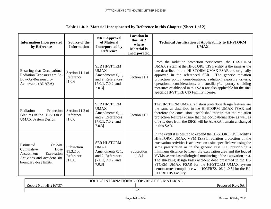
HOLTEC INTERNATIONAL COPYRIGHTED MATERIAL
Report No.: HI-2167374 Proposed Rev. 0A
11-2
Table 11.0.1: Material Incorporated by Reference in this Chapter (Sheet 1 of 2)
Information Incorporated
by Reference
Source of the
Information
NRC Approval
of Material
Incorporated by
Reference
Location in
this SAR
where
Material is
Incorporated
Technical Justification of Applicability to HI-STORM
UMAX
Ensuring that Occupational
Radiation Exposures are As-
Low-As-Reasonably-
Achievable (ALARA)
Section 11.1 of
Reference
[1.0.6]
SER HI-STORM
UMAX
Amendments 0, 1,
and 2, References
[7.0.1, 7.0.2, and
7.0.3]
Section 11.1
From the radiation protection perspective, the HI-STORM
UMAX system at the HI-STORE CIS Facility is the same as the
one described in the HI-STORM UMAX FSAR and originally
approved in the referenced SER. The generic radiation
protection policy considerations, radiation exposure criteria,
operational considerations, and auxiliary/temporary shielding
measures established in this SAR are also applicable for the site-
specific HI-STORE CIS Facility license.
Radiation Protection
Features in the HI-STORM
UMAX System Design
Section 11.2 of
Reference
[1.0.6]
SER HI-STORM
UMAX
Amendments 0, 1,
and 2, References
[7.0.1, 7.0.2, and
7.0.3]
Section 11.2
The HI-STORM UMAX radiation protection design features are
the same as described in the HI-STORM UMAX FSAR and
therefore the conclusions established therein that the radiation
protection features ensure that the occupational dose as well as
off-site dose from the ISFSI will be ALARA, remain unchanged
in this SAR.
Estimated On-Site
Cumulative Dose
Assessment - Excavation
Activities and accident site
boundary dose limits.
Subsection
11.3.2 of
Reference
[1.0.6]
SER HI-STORM
UMAX
Amendments 0, 1,
and 2, References
[7.0.1, 7.0.2, and
7.0.3]
Subsection
11.3.1
In the event it is desired to expand the HI-STORE CIS Facility's
HI-STORM UMAX VVM ISFSI, radiation protection of the
excavation activities is achieved on a site-specific level using the
same prescription as in the generic case (i.e. prescribing a
minimum distance between the excavation area and the loaded
VVMs, as well as radiological monitoring of the excavation area.
The shielding design basis accident dose presented in the HI-
STORM UMAX FSAR for the HI-STORM UMAX system
demonstrates compliance with 10CFR72.106 [1.0.5] for the HI-
STORE CIS Facility.
ATTACHMENT 3 TO HOLTEC LETTER 5025025
Page 444 of 604 Revision 0C May 2018
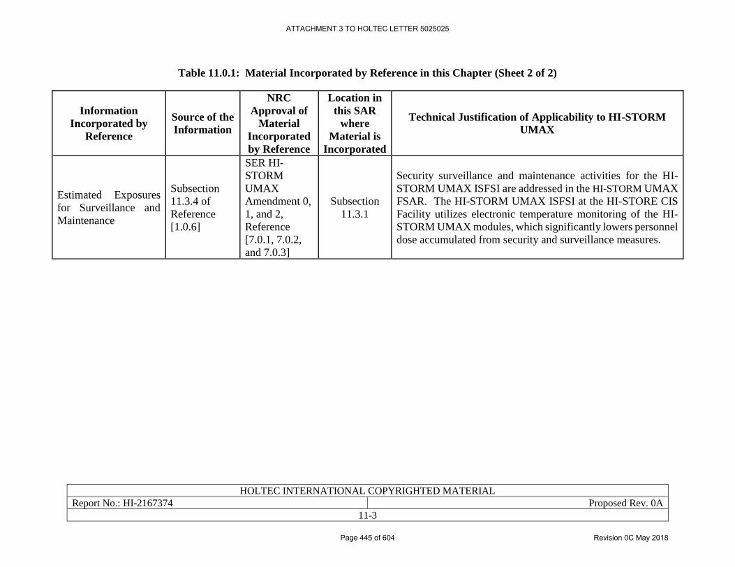
HOLTEC INTERNATIONAL COPYRIGHTED MATERIAL
Report No.: HI-2167374 Proposed Rev. 0A
11-3
Table 11.0.1: Material Incorporated by Reference in this Chapter (Sheet 2 of 2)
Information
Incorporated by
Reference
Source of the
Information
NRC
Approval of
Material
Incorporated
by Reference
Location in
this SAR
where
Material is
Incorporated
Technical Justification of Applicability to HI-STORM
UMAX
Estimated Exposures
for Surveillance and
Maintenance
Subsection
11.3.4 of
Reference
[1.0.6]
SER HI-
STORM
UMAX
Amendment 0,
1, and 2,
Reference
[7.0.1, 7.0.2,
and 7.0.3]
Subsection
11.3.1
Security surveillance and maintenance activities for the HI-
STORM UMAX ISFSI are addressed in the HI-STORM UMAX
FSAR. The HI-STORM UMAX ISFSI at the HI-STORE CIS
Facility utilizes electronic temperature monitoring of the HI-
STORM UMAX modules, which significantly lowers personnel
dose accumulated from security and surveillance measures.
ATTACHMENT 3 TO HOLTEC LETTER 5025025
Page 445 of 604 Revision 0C May 2018
HOLTEC INTERNATIONAL COPYRIGHTED MATERIAL
Report No.: HI-2167374 Proposed Rev. 0A
11-4
11.1 AS LOW AS REASONABLY ACHIEVABLE CONSIDERATIONS
11.1.1 ALARA Policies and Programs
A Radiation Protection Program is implemented at the CIS Facility in accordance with
requirements of 10CFR72.126, 10CFR20.1101, and 10CFR19.12 [1.0.5], [7.4.1], and [11.1.1].
The program draws upon the experience and expertise of programs and personnel of Holtec
International and utilities that plan to transport radioactive waste to the CIS Facility.
Section 11.1 of the HI-STORM UMAX FSAR [1.0.6] is incorporated by reference into this SAR,
and describes radiation protection policy considerations, radiation exposure criteria, operational
considerations, and auxiliary/temporary shielding measures applicable to the HI-STORE CIS
Facility, as described in Table 11.0.1 of this SAR.
The primary goal of the Radiation Protection Program is to minimize exposure to radiation such
that the individual and collective exposure to personnel in all phases of operation and maintenance
are kept ALARA. This is accomplished by integrating ALARA concepts into design, construction,
and operation of the facility.
Trained personnel develop and conduct the Radiation Protection Program and will assure that
procedures are followed to meet CIS Facility and regulatory requirements. Training programs in
the basics of radiation protection and exposure control is provided to all facility personnel whose
duties require working in radiation areas.
Basic objectives of the ALARA program are:
1 Protection of personnel, including surveillance and control over internal and external
radiation exposure to maintain individual exposures within permissible limits and ALARA,
and to keep the annual integrated (collective) dose to facility personnel ALARA.
2 Protection of the public, including surveillance and control over all conditions and
operations that may affect the health and safety of the public.
The radiation protection staff is responsible for and has the appropriate authority to maintain
occupational exposures as far below the specified limits as reasonably achievable. Ongoing
reviews are performed to determine how exposures might be reduced. The program ensures that
CIS Facility personnel receive sufficient training and that radiation protection personnel have
sufficient authority to enforce safe facility operation. Periodic training and exercises are conducted
for management, radiation workers, and other site employees in radiation protection principles and
procedures, protective measures, and emergency responses. Revisions to operating and
maintenance procedures and modifications to CIS Facility equipment and facilities are made when
the proposed revisions will substantially reduce exposures at a reasonable cost. The program also
ensures that adequate equipment and supplies for radiation protection work are provided.
The CIS Facility is committed to a strong ALARA program. The ALARA program follows the
guidelines of Regulatory Guides 8.8 [11.1.2] and 8.10 [11.1.3] and the requirements of 10 CFR 20
[7.4.1]. Management is committed to compliance with regulatory requirements regarding control
of personnel exposures and establishes and maintain a comprehensive program at the CIS Facility
to keep individual and collective doses ALARA. Management will assure that each staff member
integrates appropriate radiation protection controls into work activities. CIS Facility personnel are
ATTACHMENT 3 TO HOLTEC LETTER 5025025
Page 446 of 604 Revision 0C May 2018
HOLTEC INTERNATIONAL COPYRIGHTED MATERIAL
Report No.: HI-2167374 Proposed Rev. 0A
11-5
trained and updated on ALARA practices and dose reduction techniques to assure that each
individual understands and follows procedures to maintain his/her radiation dose ALARA.
Design, operation, and maintenance activities are reviewed to ensure ALARA criteria are met.
The ALARA program ensures that:
1 An effective ALARA program is administered at the CIS Facility that appropriately
integrates management philosophy and NRC regulatory requirements and guidance.
2 CIS Facility design features, operating procedures, and maintenance practices are in
accordance with ALARA program guidelines. Formal periodic reviews of the Radiation
Protection Program will assure that objectives of the ALARA program are attained.
3 Pertinent information concerning radiation exposure of personnel is reflected in design and
operation.
4 Appropriate experience gained during the operation of nuclear power stations relative to
radiation control is factored into procedures, and revisions of procedures, to assure that the
procedures continually meet the objectives of the ALARA program.
5 Necessary assistance is provided to ensure that operations, maintenance, and
decommissioning activities are planned and accomplished in accordance with ALARA
objectives.
6 Trends in CIS Facility personnel and job exposures are reviewed to permit corrective
actions to be taken with respect to adverse trends.
7 When it is not practicable to apply process controls or other engineering controls, dose
reduction techniques such as access control, limitation of exposure times, and other
controls in accordance with 10CFR20.1702 [7.4.1] may be used.
CIS Facility personnel are responsible for ensuring that activities are planned and accomplished in
accordance with the objectives of the ALARA program. Staff will ensure that procedures and their
revisions are implemented in accordance with the objectives of the ALARA program, and that
radiation protection staff is consulted as necessary for assistance in meeting ALARA program
objectives. Individual radiation doses, and collective doses associated with tasks controlled by
radiation work permits, are tracked to identify trends and support development of alternative
procedures that result in lower doses.
11.1.2 Design Considerations
ALARA considerations have been incorporated into the CIS Facility design, in accordance with
10CFR72.126(a) [1.0.5], based upon the layout of the CIS Facility area and the type of spent fuel
storage system selected. The following summarizes the design considerations:
• The HI-STORM UMAX ISFSI is located at least 400 meters (1312 feet) to the controlled
area boundary. This provides an acceptable distance from radiation sources to offsite
personnel to ensure dose rates at the controlled area boundary are minimized and
maintained within specified limits.
• The HI-STORM UMAX ISFSI has been sized to allow adequate spacing between
Vertically Ventilated Modules (VVMs) to permit workers to function efficiently during
ATTACHMENT 3 TO HOLTEC LETTER 5025025
Page 447 of 604 Revision 0C May 2018
HOLTEC INTERNATIONAL COPYRIGHTED MATERIAL
Report No.: HI-2167374 Proposed Rev. 0A
11-6
loading/unloading operations at the ISFSI and during performance of maintenance (e.g.
clearing blockage from the inlet ducts and surveillances. Adequate work space helps to
minimize time spent by workers in the vicinity of storage casks, limiting worker dose.
• The storage system design is based on a metal canister that is sealed by welding for spent
fuel confinement, preventing release of radionuclides from inside the canister. Radioactive
effluents are thus precluded by design. This meets the intent of 10CFR72.24(e)(l) and
10CFR72.126(d) [1.0.5], which requires that the ISFSI design provide means to limit the
release of radioactive materials in effluents during normal operations to levels that are
ALARA. There are no radioactive effluents released from the CIS Facility during normal
operations. This passive system design also requires minimum maintenance and
surveillance requirements by personnel.
• The data acquisition of the VVM temperature monitoring system enables remote readout
of temperatures representative of cask thermal performance, avoiding time spent by CIS
staff to perform daily walkdowns, or take measurements, or read instrumentation in the
vicinity of the HI-STORM UMAX ISFSI.
• Holtec International, the vendor of the spent fuel storage system, has incorporated a number
of design features to provide ALARA conditions during transportation, handling, and
storage as described in its HI-STORM UMAX Final Safety Analysis Report [1.0.6].
• Where practical, power operated wrenches are used to reduce the times associated with
tasks involving bolt insertion and removal during transport cask receipt and canister
transfer operations. This minimizes times spent in radiation fields. Temporary shielding
is used where it is determined to be effective in reducing total dose for a task (considering
doses to personnel involved in its installation and removal).
Regulatory Position 2 of Regulatory Guide 8.8 [11.1.2] is incorporated into design considerations,
as described below:
• Regulatory Position 2a on access control is met by use of a fence with a locked gate that
surrounds the HI-STORM UMAX ISFSI and prevents unauthorized access.
• Regulatory Position 2b on radiation shielding is met by the heavy shielding of the shipping,
storage, and transfer casks, which minimizes personnel exposures during transport cask
reception, canister transfer, canister storage, and offsite shipment operations. The designs
of the storage cask air inlet and outlet ducts prevent direct radiation streaming. The
Canister Transfer Building is positioned a substantial distance (as shown in Figure 2.1.4)
from the HI-STORM UMAX ISFSI to minimize dose from the ISFSI to personnel during
operations taking place in the Canister Transfer Building. The designs of the shipping,
storage, transfer casks and auxiliary equipment assure adequate shielding for personnel
inside the Cask Transfer Building.
• The Security and Administrative Buildings is also positioned a substantial distance (as
shown in Figure 2.1.4) from the HI-STORM UMAX ISFSI to minimize dose from the
ISFSI to personnel residing in this building.
• Regulatory Position 2c on process instrumentation is met since the cask temperature
monitoring system utilizes a data acquisition system to record cask temperature
ATTACHMENT 3 TO HOLTEC LETTER 5025025
Page 448 of 604 Revision 0C May 2018
HOLTEC INTERNATIONAL COPYRIGHTED MATERIAL
Report No.: HI-2167374 Proposed Rev. 0A
11-7
instrumentation readings, avoiding time spent by CIS Facility staff to make daily cask vent
blockage surveillances and to read instrumentation in the vicinity of the storage casks.
• Regulatory Position 2d on control of airborne contaminants is not applicable because
gaseous releases are precluded by the sealed canister design. No significant surface
contamination is expected on the outer surfaces of the canister since process controls are
maintained during fuel loading into the canister at the originating nuclear power plants.
Additionally, the nuclear power plant shipping the cask is required to demonstrate
compliance with 49CFR173.443 [10.3.1], which places strict controls on non-fixed
contamination.
• Regulatory Position 2e on crud control is not applicable to the CIS Facility because there
are no systems at the CIS Facility that could produce crud.
• Regulatory Position 2f on decontamination is met because the internal surfaces of shipping,
transfer, and storage casks have hard surfaces that lend themselves to decontamination by
wiping. Interior surfaces of the Canister Transfer Building are painted with a special paint
that is easily decontaminated.
• Regulatory Position 2g on radiation monitoring is met with the use of area radiation
monitors in the Canister Transfer Building for monitoring general area dose rates from the
casks and canisters during canister transfer operations, and with thermoluminescent
dosimeters (TLDs) along the perimeters of the RA and OCA to provide information on
radiation doses. Continuous air monitors, if deemed necessary, are located in the exhaust
of the Canister Transfer Building (Subsection 11.2.5) and/or available as portable air
samplers.
• Regulatory Position 2h on resin treatment systems is not applicable to the CIS Facility
because there are not any radioactive systems containing resins.
• Applicable portions of Regulatory Position 2i concerning other miscellaneous ALARA
items is met because CIS Facility features provide a favorable working environment and
promote efficiency (Paragraph 2i(13)) [11.1.2]. These include:
o Adequate lighting in the Canister Transfer Building, and HI-STORM UMAX
ISFSI; adequate ventilation in the Canister Transfer Building;
o Adequate working space in the Canister Transfer Building and at the HI-STORM
UMAX ISFSI; and accessibility – with platforms or scaffolding and ladders that
facilitate ready access to the tops of the transport casks and storage casks and to the
transfer cask doors where operators need to perform tasks during canister transfer
operations.
o Regulatory Position 2i(15) is met because the emergency lighting system is
adequate to permit prompt egress from any high radiation areas that could possibly
exist in the vicinity of the canister/casks during canister transfer operations.
11.1.3 Operational Considerations
Specific CIS Facility operational considerations to achieve ALARA conditions are as follows:
ATTACHMENT 3 TO HOLTEC LETTER 5025025
Page 449 of 604 Revision 0C May 2018
HOLTEC INTERNATIONAL COPYRIGHTED MATERIAL
Report No.: HI-2167374 Proposed Rev. 0A
11-8
• Fuel loading operations take place at the originating nuclear power plants, away from the
CIS Facility. There are no assembly handling operations at the CIS Facility.
• No significant surface contamination is expected on the canisters as the result of controls
applied during the fuel loading operations at the originating nuclear power plants. Workers
therefore are not exposed to significant surface contamination or airborne contamination
during canister transfer operations.
• Canister transfer between the transport cask and the HI-STORM UMAX VVM will take
place within a shielded transfer cask.
• Prior to canister transfer operations, “dry runs” are performed to train personnel on canister
transfer procedures, discuss methods to minimize exposures, and refine procedures to
achieve minimum probable exposures.
• The CIS Facility procedures and work practices reflect ALARA lessons learned from other
ISFSIs that use VVMs, as applicable.
• Operations research is performed to determine types of tools, portable shielding, and
equipment that helps to minimize exposures to workers involved in canister transfer
operations.
• The gantry crane located in the Canister Transfer Building is single-failure proof and is
designed to withstand the design basis ground motion, as described in Chapter 5. The
gantry crane, whose range of travel covers the length and width of the Canister Transfer
Building, handles the transport casks and moves the transport casks from a horizontal
orientation on the inbound rail car to a vertical orientation where it can be placed in the
Canister Transfer Facility (indoor pit).
• The Vertical Cask Transporter (VCT) is used to move the HI-TRAC CS (transfer cask)
from the Canister Transfer Building to the HI-STORM UMAX ISFSI. The VCT requires
minimum personnel and allows for quick and accurate placement of a storage cask.
• The storage systems do not require any systems that process liquids or gases or contain,
collect, store, or transport radioactive liquids. Therefore, there are no such systems to be
maintained or operated.
Regulatory Position 4 of Regulatory Guide 8.8 is met with the use of area radiation monitors in
the Canister Transfer Building and TLDs around the Restricted Area fence and the Controlled Area
boundary. In addition, radiation protection personnel use portable monitors during transport cask
receipt, inspection, and canister transfer operations, and the operating staff will have personal
dosimetry (Subsection 11.4.2). The access control point is at the Security Building, as described
in Subsection 11.4.2.
Protective equipment, that may include anti-contamination clothing and respirators, is available in
the Security Building and controlled by radiation protection personnel. Airborne monitoring is
performed using portable monitors as needed.
Regulatory Guide 8.10 [11.1.3] is incorporated into the CIS Facility operational considerations as
described below:
ATTACHMENT 3 TO HOLTEC LETTER 5025025
Page 450 of 604 Revision 0C May 2018
HOLTEC INTERNATIONAL COPYRIGHTED MATERIAL
Report No.: HI-2167374 Proposed Rev. 0A
11-9
1 Facility personnel are made aware of management’s commitment to keep occupational
exposures ALARA.
2 Ongoing reviews are performed to determine how exposures might be lowered.
3 There is a well-supervised radiation protection capability with specific, defined
responsibilities.
4 Facility workers receive sufficient training.
5 Sufficient authority to enforce safe facility operation is provided to radiation protection
personnel.
6 Modification to operating and maintenance procedures and to equipment and facilities are
made where they substantially reduce exposures at a reasonable cost.
7 The radiation protection staff understands the origins of radiation exposures in the facility
and seeks ways to reduce exposures.
8 Adequate equipment and supplies for radiation protection work are provided.
ATTACHMENT 3 TO HOLTEC LETTER 5025025
Page 451 of 604 Revision 0C May 2018
HOLTEC INTERNATIONAL COPYRIGHTED MATERIAL
Report No.: HI-2167374 Proposed Rev. 0A
11-10
11.2 RADIATION PROTECTION DESIGN FEATURES
The HI-STORM UMAX radiation protection design features are incorporated by reference from
Section 11.2 of [1.0.6], as described in Table 11.0.1 of this SAR.
11.2.1 Installation Design Features
A description of the CIS Facility layout and design is provided in Section 2.1. The CIS Facility
layout and design are in accordance with the facility and equipment design features identified in
Position 2 of Regulatory Guide 8.8 [11.1.2], as described in Subsection 11.1.2.
The CIS Facility has the following design features that ensure that exposures are ALARA:
• The site is located far from population centers [1.0.4].
• The nearest resident is 1.5 miles (2.41 km) north of the site, as shown in Table 1.0.1.
• The only sources of radiation at the CIS Facility are the sealed canisters containing spent
fuel assemblies. These canisters are always shielded by shipping, storage, or by transfer
casks during canister transfer operations.
• Measures are taken at the originating nuclear power plants to prevent loose surface
contamination levels on the exterior of the canisters. Controls assure that canisters are not
transported to the CIS Facility unless contamination levels are within specified limits.
• The canisters are sealed by welding, eliminating the potential for release of radioactive
gases or particles.
• The canisters are never opened, nor will spent fuel assemblies be unloaded at the CIS
Facility.
• The fuel assemblies are stored dry inside the canisters, so that no radioactive liquid is
available for release.
• The shipping, transfer, and HI-STORM UMAX VVMs are heavily shielded to minimize
external dose rates.
• The CIS Facility site layout provides substantial distance between the HI-STORM UMAX
ISFSI and the Controlled Area boundary, as shown in Table 1.0.1, minimizing radiation
exposures to individuals outside the controlled area boundary and assuring offsite dose
rates are below the 10CFR72.104 [1.0.5] criteria.
• The location of the Canister Transfer Building inside the Restricted Area (RA) minimizes
the route between the Canister Transfer Building and the HI-STORM UMAX ISFSI,
provides for minimal other traffic on the route, and maintains substantial distance from the
Controlled Area boundary.
• There are no radioactive liquid wastes associated with the CIS Facility.
The CIS Facility building ventilation systems are not designed for any special radiological
considerations since there is no credible scenario for which a significant radioactive release would
occur. Shielding of the canister is provided by the HI-STORM UMAX systems and by the
shipping and transfer casks during canister receipt, transfer, and offsite shipping operations.
ATTACHMENT 3 TO HOLTEC LETTER 5025025
Page 452 of 604 Revision 0C May 2018
HOLTEC INTERNATIONAL COPYRIGHTED MATERIAL
Report No.: HI-2167374 Proposed Rev. 0A
11-11
The general area inside the RA fence is a Restricted Area, as defined by 10CFR20 [7.4.1], and is
controlled in accordance with applicable requirements of 10CFR20, with personnel dosimetry
required. Certain areas within the Restricted Area are designated as Radiation Areas, and specific
locations within the RA have the potential to be High Radiation Areas, and are posted and
controlled in accordance with applicable requirements of 10CFR20 [7.4.1]. The cask load/unload
bay, crane bay, cask transporter bay, and canister transfer cells inside the Canister Transfer
Building are designated as Radiation Areas whenever loaded canisters are present in these areas,
since the potential exists for dose rates to exceed 5 mrem/hr in these areas. Upon removal of the
impact limiters from the transport casks in the Canister Transfer Building, the potential exists for
dose rates in the vicinity of the top and or bottom of the casks to exceed 100 mrem/hr in localized
areas, and these localized areas will be posted as High Radiation Areas, with necessary controls
applied. Due to distances from the transport casks when their impact limiters are removed, dose
rates outside the Canister Transfer Building are well below 100 mrem/hr.
11.2.2 Access Control
The CIS Facility is designed to provide access control in accordance with 10CFR72. Access
control to the RA is provided for both personnel radiological protection and facility physical
protection. The physical protection program is covered in the Security Plan, which is classified
and submitted as part of the License Application under separate cover.
The access control boundary for the restricted area are established along the security fence lines
(see Figure 2.1.4). The RA is that space which is controlled for purposes of protecting individuals
from exposure to radiation or radioactive materials and for providing facility physical security.
Operational controls ensure the total effective dose equivalent to individual members of the public
from the licensed operation does not exceed 0.1 rem in accordance with 10CFR20.1301(a)(1)
[7.4.1]. The boundary for the RA is the security fence where the dose rate is less than 2 mrem/hr,
in accordance with 10CFR20.1301(a)(2) [7.4.1]. The controlled area is the area inside the site
boundary. The dose rate beyond the controlled area is less than 25 mrem/year, in accordance with
10CFR72.104 [1.0.5].
Access to the RA is controlled through a single access point in the Security Building (See Figure
2.1.4). Personal dosimetry is issued and controlled in this building to individuals entering the
Restricted Area (RA). Provisions exist in this building for donning and removing personal
protective equipment, such as anti-contamination clothing and/or respirators if deemed necessary,
in the event of contamination in the Canister Transfer Building as a result of off-normal or accident
conditions. Provisions for personnel decontamination are also contained in the Security Building.
The Restricted Area also includes the cask storage area and Canister Transfer Building. In
accordance with the CIS Facility Radiation Protection Program (Section 11.4), radiation protection
personnel monitor radiation levels in the RA and establish access requirements as needed.
11.2.3 Radiation Shielding
The HI-STORM UMAX VVMs are designed to maintain radiation exposures ALARA. No low-
level radioactive waste (LLW) materials are expected to be generated on site, and there are no
special design provisions for low-level radioactive waste materials are not required.
In the unlikely event that low level waste is generated on site such as for smears, disposable
clothing, tape, blotter paper, rags, and related health physics material, this material will be
ATTACHMENT 3 TO HOLTEC LETTER 5025025
Page 453 of 604 Revision 0C May 2018
HOLTEC INTERNATIONAL COPYRIGHTED MATERIAL
Report No.: HI-2167374 Proposed Rev. 0A
11-12
processed and temporarily stored on-site while awaiting removal to a licensed LLW disposal
facility. The material will be packaged and stored in sealed LLW containers. The LLW containers
provide necessary shielding, and dose rates on the outside surfaces of the drums are expected to
be negligible. In the unlikely event that LLW materials are stored on-site with significant activity
levels, temporarily located shielding may be used to maintain dose rates in the area ALARA, as
determined by radiation protection personnel.
11.2.3.1 Shielding Configurations
Chapter 5 of the HI-STORM UMAX FSAR [1.0.6] identifies the shielding materials and
geometries of the HI-STORM UMAX system and describes the codes used to model shielding and
assess cask dose rates. Further descriptions of site specific shielding configurations are provided
in Chapter 7 of this SAR.
11.2.4 Confinement and Ventilation
10CFR72.122(h)(3) [1.0.5] requires that ventilation systems and off-gas systems be provided
where necessary to ensure the confinement of airborne radioactive particulate materials during
normal or off-normal conditions. However, there are no special ventilation systems installed at
the CIS Facility buildings. There are no credible scenarios that would require installation of
ventilation systems to protect against off-gas or particulate filtration.
11.2.5 Area Radiation and Airborne Radioactivity Monitoring Instrumentation
10CFR72.122(h)(4) [1.0.5] requires the capability for continuous monitoring of the storage system
to enable the licensee to determine when corrective action needs to be taken to maintain safe
storage conditions. This is not applicable to the CIS Facility because the canisters are sealed by
welding and with the canisters in HI-STORM UMAX systems, there are no credible events that
could result in releases of radioactive material from within the canisters or unacceptable increases
in direct radiation levels, as described in Chapter 9. Area radiation and airborne radioactivity
monitors are therefore not needed at the storage pads. However, TLDs are used to record dose
rates in the Restricted Area and along the Controlled Area boundary. TLDs provide a passive
means for continuous monitoring of radiation levels and provide a basis for assessing the potential
impact on the environment.
TLDs are located at the Restricted Area fence and at the Controlled Area Boundary in accordance
with 10CFR20.1302 [7.4.1]. Additionally, TLDs are located at strategic locations inside the
Canister Transfer Building, Security Building, and Administration Building where personnel are
normally working. These TLDs serve as a backup for monitoring personnel radiation exposure
and maintaining this exposure ALARA. For redundancy, each TLD location mentioned above
house a set of two TLDs. The TLDs are retrieved and processed quarterly. The TLDs primarily
detect gamma radiation and have a lower limit of sensitivity of (0.02 mrem). The storage system
design is based on a metal canister that is sealed by welding for spent fuel confinement, preventing
release of radionuclides from inside the canister. Radioactive effluents are thus precluded by
design.
Local radiation monitors with audible alarms are installed in the Canister Transfer Building. These
provide warning to personnel involved in the canister transfer operation of abnormal radiation
levels that could possibly occur during transfer operations. Because of measures taken at the
ATTACHMENT 3 TO HOLTEC LETTER 5025025
Page 454 of 604 Revision 0C May 2018
HOLTEC INTERNATIONAL COPYRIGHTED MATERIAL
Report No.: HI-2167374 Proposed Rev. 0A
11-13
originating nuclear power plants to minimize loose surface contamination levels on the exterior of
the canisters during fuel loading operations, as discussed in Subsection 11.1.3, it is unlikely that
canister transfer operations would generate significant levels of airborne contaminants. Local
continuous air monitors include alarms to warn operating personnel in the unlikely event of an
airborne release, remote alarm in the Security Building alarm station to ensure coverage at all
times, and charting capability to provide data necessary to quantify any release. The radiological
alarm systems are designed with provisions for calibration and operability testing. There are no
liquid or gaseous effluent releases from the CIS Facility. This satisfies the requirements of
10CFR72.24(e)(l) and 10CFR72.126(b)(c) [1.0.5].
ATTACHMENT 3 TO HOLTEC LETTER 5025025
Page 455 of 604 Revision 0C May 2018
HOLTEC INTERNATIONAL COPYRIGHTED MATERIAL
Report No.: HI-2167374 Proposed Rev. 0A
11-14
11.3 DOSE ASSESSMENT
11.3.1 Onsite Dose
The shipping, transfer, and storage casks are designed to limit dose rates to ALARA levels for
operators, inspectors, maintenance, and radiation protection personnel when the canisters are being
transferred from the shipping to the transfer casks, when the transfer cask is being moved to the
ISFSI, and while the canisters are transferred from the transfer cask to the HI-STORM UMAX
VVMs.
HI-TRAC CS dose rates at the surface, 0.5 meter, 1 meter, and 2 meter distances are presented in
Table 7.4.1. HI-STORM UMAX Version C dose rates at the surface and at 1 meter are presented
in Table 7.4.2.
Table 11.3.1 shows the estimated occupational exposures to CIS Facility personnel during receipt
of the transport cask and transfer of the canister from the transport cask to the HI-STORM UMAX
using the HI-TRAC CS transfer cask. The operational sequence for these operations is also
described in Chapter 3.
Dose rate values include both gamma and neutron flux components, and are based on design basis
PWR fuel as shown in Table 7.1.1. Fuel with these characteristics is considered to conservatively
represent fuel assemblies that are contained in canisters handled at the CIS Facility, and dose
estimates based on fuel with these characteristics are considered to be realistic and reflect expected
personnel exposures.
Occupational doses to individuals are administratively controlled to ensure that they are
maintained below 10 CFR 20.1201 limits. Temporarily positioned shielding is used during transfer
operations to reduce dose rates from streaming paths or relatively high radiation areas where its
use results in a net reduction in worker exposures. Conservatively, the effects of temporarily
positioned shielding are not considered in the Table 11.3.1 dose estimates for canister transfer
operations. It is expected the actual crew dose per loading would be significantly less than what
is presented in Table 11.3.1, and operational experience gained with each loading also has been
shown to lower crew dose on subsequent loadings.
The shielding design basis accident dose analysis for the HI-STORM UMAX system presented in
Subsection 11.3.2 of Reference [1.0.6] is incorporated by reference as described in Table 11.0.1.
Additionally, in the event it is desired to expand the HI-STORE CIS Facility’s HI-STORM UMAX
VVM ISFSI, radiation protection of excavation activities is incorporated by reference from Section
11.3.2 of Reference [1.0.6] as described in Table 11.0.1.
Occupational exposures are also estimated to security personnel and CIS Facility personnel that
conduct inspections, surveillances, and maintain the storage systems. Subsection 11.3.4 of the HI-
STORM UMAX FSAR [1.0.6], which addresses estimated exposures for security surveillance and
maintenance, is incorporated by reference into this SAR as described in Table 11.0.1.
11.3.2 Offsite Dose
The offsite dose evaluation is provided in Section 7.4, with results in Table 7.4.3 and Table 7.4.4.
ATTACHMENT 3 TO HOLTEC LETTER 5025025
Page 456 of 604 Revision 0C May 2018
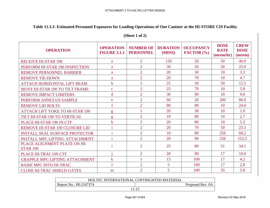
HOLTEC INTERNATIONAL COPYRIGHTED MATERIAL
Report No.: HI-2167374 Proposed Rev. 0A
11-15
Table 11.3.1: Estimated Personnel Exposures for Loading Operations of One Canister at the HI-STORE CIS Facility
(Sheet 1 of 2)
OPERATION OPERATION
FIGURE 3.1.1
NUMBER OF
PERSONNEL
DURATION
(MINS)
OCCUPANCY
FACTOR (%)
DOSE
RATE
(mrem/hr)
CREW
DOSE
(mrem)
RECEIVE HI-STAR 190 a 2 120 20 50 40.0
PERFORM HI-STAR 190 INSPECTION a 2 30 50 50 25.0
REMOVE PERSONNEL BARRIER a 2 20 50 10 3.3
REMOVE TIE-DOWN a 2 20 70 10 4.7
ATTACH HORIZONTAL LIFT BEAM b 2 25 30 50 12.5
MOVE HI-STAR 190 TO TILT FRAME c 2 25 70 10 5.8
REMOVE IMPACT LIMITERS d 2 30 90 10 9.0
PERFORM ANNULUS SAMPLE e 2 60 20 200 80.0
REMOVE LID BOLTS f 2 80 90 10 24.0
ATTACH LIFT YOKE TO HI-STAR 190 g 1 20 30 10 1.0
TILT HI-STAR 190 TO VERTICAL g 2 10 80 10 2.7
PLACE HI-STAR 190 IN CTF h 2 20 80 10 5.3
REMOVE HI-STAR 190 CLOSURE LID i 2 20 70 50 23.3
INSTALL SEAL SURFACE PROTECTOR i 2 10 80 256 68.2
INSTALL MPC LIFTING ATTACHMENT i 2 20 90 256 153.5
PLACE ALIGNMENT PLATE ON HI-
STAR 190 i 2 25 80 51 34.1
PLACE HI-TRAC ON CTF j 2 20 90 17 10.0
GRAPPLE MPC LIFTING ATTACHMENT k 1 15 100 17 4.2
RAISE MPC INTO HI-TRAC l 2 5 100 17 2.8
CLOSE HI-TRAC SHIELD GATES m 2 5 100 35 5.8
ATTACHMENT 3 TO HOLTEC LETTER 5025025
Page 457 of 604 Revision 0C May 2018
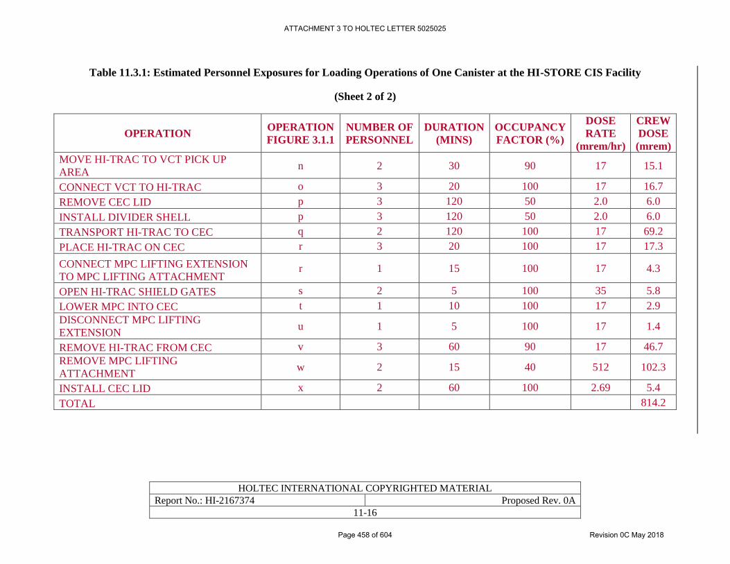
HOLTEC INTERNATIONAL COPYRIGHTED MATERIAL
Report No.: HI-2167374 Proposed Rev. 0A
11-16
Table 11.3.1: Estimated Personnel Exposures for Loading Operations of One Canister at the HI-STORE CIS Facility
(Sheet 2 of 2)
OPERATION OPERATION
FIGURE 3.1.1
NUMBER OF
PERSONNEL
DURATION
(MINS)
OCCUPANCY
FACTOR (%)
DOSE
RATE
(mrem/hr)
CREW
DOSE
(mrem)
MOVE HI-TRAC TO VCT PICK UP
AREA n 2 30 90 17 15.1
CONNECT VCT TO HI-TRAC o 3 20 100 17 16.7
REMOVE CEC LID p 3 120 50 2.0 6.0
INSTALL DIVIDER SHELL p 3 120 50 2.0 6.0
TRANSPORT HI-TRAC TO CEC q 2 120 100 17 69.2
PLACE HI-TRAC ON CEC r 3 20 100 17 17.3
CONNECT MPC LIFTING EXTENSION
TO MPC LIFTING ATTACHMENT r 1 15 100 17 4.3
OPEN HI-TRAC SHIELD GATES s 2 5 100 35 5.8
LOWER MPC INTO CEC t 1 10 100 17 2.9
DISCONNECT MPC LIFTING
EXTENSION u 1 5 100 17 1.4
REMOVE HI-TRAC FROM CEC v 3 60 90 17 46.7
REMOVE MPC LIFTING
ATTACHMENT w 2 15 40 512 102.3
INSTALL CEC LID x 2 60 100 2.69 5.4
TOTAL 814.2
ATTACHMENT 3 TO HOLTEC LETTER 5025025
Page 458 of 604 Revision 0C May 2018
HOLTEC INTERNATIONAL COPYRIGHTED MATERIAL
Report No.: HI-2167374 Proposed Rev. 0A
11-17
11.4 RADIATION PROTECTION PROGRAM
11.4.1 Organizational Structure
The CIS Facility Radiation Protection Manager reports to the Site Manager (Figure 10.4.2) and is
responsible for administering the radiation protection program and for the radiation safety of the
facility. Minimum qualification requirements are set forth in Chapter 10.
Responsibilities of the CIS Facility Radiation Protection Manager include the following:
• Administer the Radiation Protection program policies and procedures
• Review and approve radiation protection procedures
• Coordinate radiation protection group activities with operations and maintenance
personnel
• Ensure adequate staffing, facilities, and equipment are available to perform the functions
assigned to radiation protection personnel
• Establish goals for the Radiation Protection program
• Initiate and implement exposure control program that factors dosimetry results into
operational planning
• Issue or rescind “stop work” orders as appropriate
• Ensure that locations, operations, and/or conditions that have potential for causing
significant exposures to radiation are identified and controlled
• Review and approve training programs related to work in radiological areas or involving
radioactive material
• Administer shipments (if necessary) of solid radioactive waste offsite for disposal
• Review root causes and corrective actions for incidents and deficiencies associated with
Radiation Protection
• Ensure an effective ALARA program is maintained, in accordance with the guidance
provided in Regulatory Guides 8.8 [11.1.2] and 8.10 [11.1.3]
• Supervise the collection, analysis and evaluation of data obtained from radiological surveys
and monitoring activities in accordance with 10CFR20.1501 [7.4.1]
• Participate in the event of an emergency, as required
Radiation protection technicians report to the Radiation Protection Manager. Responsibilities of
the radiation protection technicians include the following:
• Conduct radiation, contamination, and airborne surveys and prepare complete and accurate
records
• Prepare Radiation Work Permits to control access to and activities in radiologically
controlled areas
ATTACHMENT 3 TO HOLTEC LETTER 5025025
Page 459 of 604 Revision 0C May 2018
HOLTEC INTERNATIONAL COPYRIGHTED MATERIAL
Report No.: HI-2167374 Proposed Rev. 0A
11-18
• Identify and post radiation, contamination, hot particle, airborne and radioactive material
areas in accordance with 10 CFR 20 [7.4.1] requirements
• Monitor CIS Facility operations to assure good radiological work practices
• Implement ALARA program requirements
• Maintain and calibrate portable monitoring instruments
• Issue “stop work” orders whenever activities have the potential to jeopardize the health and
safety of workers, visitors, or the general public
• Verify proper packaging of any radioactive material
• Participate in the event of an emergency, as required
11.4.2 Equipment, Instrumentation, and Facilities
A sufficient inventory and variety of operable and calibrated portable and fixed radiological
instrumentation is maintained to allow for effective measurement and control of radiation exposure
and radioactive material and to provide back-up capability for inoperable equipment. Equipment
is ensured to be appropriate to enable the assessment of sources of gamma, neutron, beta, and alpha
radiation, including the capability to measure dose rates and radioactivity concentrations expected.
Radiation protection procedures govern instrument calibration, instrument inventory and control,
and instrument operation.
Portable survey and personnel monitoring instrumentation, if deemed necessary during normal,
off-normal, or accident conditions, will include, but not be limited to, the following:
• Low-level contamination meters
• Beta/gamma portable survey meters
• Alarming beta/gamma personnel friskers
• Portable air samplers
Area radiation monitors are utilized in the Canister Transfer Building since the operations
performed in this building (transport cask receipt, inspection, and canister transfer operations) pose
the greatest risk to the operating staff for radiation exposure. These monitors have audible alarms
to warn operating personnel of abnormal radiation levels. Area radiation monitors are not utilized
outside the Canister Transfer Building since these areas have relatively low area radiation levels
and there are no operations performed in these areas which could result in rapid change in radiation
level and pose a risk for over-exposure of personnel.
The Restricted Area is surrounded by a chain link security fence and an outer chain link nuisance
fence with an isolation zone and intrusion detection system between the two fences. Access to the
Restricted Area is controlled through a single access point in the Security Building (see Figure
2.1.4). Personal dosimetry is issued and controlled in this building to individuals entering the
Restricted Area. External radiation dose monitoring is accomplished through the use of
thermoluminescent dosimeters (TLDs) and self-reading dosimeters (SRDs) or digital alarming
dosimeters (DADs). During transfer operations inside the Canister Transfer Building alarming
dosimeters shall be used to warn of excessively high direct radiation to maintain exposures
ATTACHMENT 3 TO HOLTEC LETTER 5025025
Page 460 of 604 Revision 0C May 2018
HOLTEC INTERNATIONAL COPYRIGHTED MATERIAL
Report No.: HI-2167374 Proposed Rev. 0A
11-19
ALARA, thereby providing assurance that occupational exposures do not exceed the limits of 10
CFR Part 20. The official record of external dose to beta and gamma radiations is normally
obtained from the TLDs with SRDs or DADs used as a means for tracking dose between TLD
processing periods as a backup to TLDs. Self-reading dosimeters are administered in accordance
with the guidance in Regulatory Guide 8.4 [11.4.1].
Provisions exist in the Security Building for donning and removing personal protective equipment,
such as anti-contamination clothing, which could be necessary in the event of contamination in the
Canister Transfer Building due to off-normal or accident conditions. A respiratory protection
program, if deemed necessary, will be established in accordance with 10 CFR 20 and consistent
with the guidance of NUREG-0041 [11.4.2].
Provisions for personnel decontamination are contained in the Security Building. Contamination
of equipment or personnel is not expected to occur under normal conditions of operation. In
accordance with the CIS Facility policy of preventing generation of liquid radioactive waste, any
necessary decontamination of equipment and personnel will be conducted using methods that
produce only solid radioactive waste. Decontamination methods would typically include wiping
the contaminated item with rags or paper wipes.
Drain sumps are provided in the cask load/unload bay of the Canister Transfer Building which
catch and collect water that drips from transport casks (e.g. from melting snow) onto the floor.
Water collected in the cask load/unload bay drain sumps is sampled and analyzed to verify it is not
contaminated prior to its release. In the event contaminated water is detected, it will be collected
in a suitable container, solidified by the addition of an agent such as cement or “Aquaset” so that
it qualifies as solid waste, staged on-site while awaiting shipment offsite, and transported to a LLW
disposal facility, in accordance with Radiation Protection procedures.
No process or effluent monitors are necessary because of the design of the CIS Facility storage
system, in which spent fuel assemblies are stored in welded canisters. During routine storage
operations at the CIS Facility, the only radiological instrumentation in use in the storage area are
the TLDs, as described in Subsection 11.2.5. Routine radiological surveys use instruments that
are controlled by the Radiation Protection Program and governed by existing procedures.
Calibration procedures for radiological instrumentation are established and applied to instruments
used at the CIS Facility.
11.4.3 Policies and Procedures
Radiation protection requirements for all radiological work at the CIS Facility are governed by
radiation protection procedures. Radiation protection practices for cask loading and unloading
operations, canister transfer, canister storage, and monitoring are also based on these procedures,
as well as on anticipated conditions when the task is to be performed. These procedures, if deemed
necessary, include, but are not limited to, the following:
• Procedure for performing badging functions for access authorization to the Restricted Area.
• Procedure for issuing personnel dosimetry, and monitoring, recording, and tracking
individual exposures.
• Procedure for performing radiological safety training and refresher training.
ATTACHMENT 3 TO HOLTEC LETTER 5025025
Page 461 of 604 Revision 0C May 2018
HOLTEC INTERNATIONAL COPYRIGHTED MATERIAL
Report No.: HI-2167374 Proposed Rev. 0A
11-20
• Procedure for performing ALARA reviews of plant procedures and monitoring of
operations.
• Procedure for determining radiation doses on a periodic basis at the Restricted Area and
Controlled Area boundaries using TLDs.
• Procedure for issuing, revising, and terminating radiation work permits and standing
radiation work permits.
• Procedure for roping off, barricading, and posting radiation control zones.
• Procedure for decontaminating personnel, equipment, and areas.
• Procedure for performing radiation surveys in accordance with 10CFR20.1501.
• Procedure for smear swab sampling, counting, and calculation.
• Procedure for calibrating detection, monitoring, and dosimetry instruments.
• Procedure for quantifying airborne radioactivity.
• Procedure for maintaining records of the radiation protection program, including audits and
other reviews of program content and implementation; radiation surveys; instrument
calibrations; individual monitoring results; and records required for decommissioning.
Implementation of the Radiation Protection Program procedures ensures that occupational doses
are below the limits required by 10 CFR 20.1201 [7.4.1]. Area radiation monitors in the Canister
Transfer Building have audible alarms and warn operating personnel of abnormal radiation levels.
While area radiation monitors are not installed in the Restricted Area, measures are in place to
ensure personnel in the Restricted Area do not exceed dose limits. Process and engineering
controls at the HI-STORE CIS Facility ensures that contamination is non-existent or minimized,
that controls are in place to ensure air concentrations of radioactive material is non-existent or
insignificantly low, and that there is no or minimal generation of radioactive waste on-site in
accordance with 10CFR20.1406 and 10CFR20.1701 [7.4.1].
As discussed in Subsection 11.2.2, access to the Restricted Area is controlled through a single
access point in the Security Building where personal dosimetry is issued to individuals entering
the Restricted Area. Periodic radiation surveys are conducted of areas inside the Restricted Area
and maps are generated showing the radiation levels in all areas. Radiation work permits (RWPs)
are completed by qualified radiation protection personnel prior to any entry and serve to identify
normal and unusual radiation readings. Workers are required to read, understand and sign that
they are aware of the conditions or unknowns. Personnel are trained to use the appropriate
radiation detection instruments or are required to have a qualified radiation protection technician
with them at all times while in the areas. Training includes responses to unusual readings and off-
scale conditions. The Radiation Protection program will provide for the immediate reading of any
individual’s TLD if an unusual reading or off-scale condition occurs.
ATTACHMENT 3 TO HOLTEC LETTER 5025025
Page 462 of 604 Revision 0C May 2018
HOLTEC INTERNATIONAL COPYRIGHTED MATERIAL
Report No.: HI-2167374 Proposed Rev. 0A
11-21
11.5 REGULATORY COMPLIANCE
The HI-STORM UMAX System at the HI-STORE CIS Facility provides radiation shielding and
confinement features that are sufficient to meet the requirements of 10CFR72.104 and
10CFR72.106 [1.0.5].
Occupational radiation exposures satisfy the limits of 10CFR20 [7.4.1] and meet the objective of
maintaining exposures ALARA.
The design of the HI-STORM UMAX System is in compliance with 10CFR72 [1.0.5] and
applicable design and acceptance criteria have been satisfied. The radiation protection system
design provides reasonable assurance that the HI-STORM UMAX System at the HI-STORE CIS
Facility allows safe storage of spent fuel.
ATTACHMENT 3 TO HOLTEC LETTER 5025025
Page 463 of 604 Revision 0C May 2018
HOLTEC INTERNATIONAL COPYRIGHTED MATERIAL
Report No.: HI-2167374 Proposed Rev. 0A
12-1
CHAPTER 12: QUALITY ASSURANCE PROGRAM
12.0 INTRODUCTION
12.0.1 Overview
This chapter provides a summary of the quality assurance program implemented by Holtec
International for activities related to the design, qualification analyses, material procurement,
fabrication, assembly, testing and use of structures, systems, and components of the Company’s
dry storage/transport systems including the HI-STORM UMAX System and other equipment at
the HI-STORE CIS facility. This chapter is included in this SAR to fulfill the requirements in
10CFR72.140(c)(2) as elaborated in NUREG-1567[1.0.3].
Important-to-safety activities related to construction and deployment of the HI-STORM UMAX
System and other equipment at the HI-STORE CIS Facility are controlled under the NRC-
approved Holtec Quality Assurance Program. The Holtec QA program manual [12.0.1]† is
approved by the NRC under Docket 71-0784. The Holtec QA program satisfies the requirements
of 10CFR72, Subpart G and 10CFR71, Subpart H. In accordance with 10CFR72.140(d), this
approved 10CFR71 QA program will be applied to spent fuel storage cask activities at HI-
STORE under 10CFR72. The additional recordkeeping requirements of 10CFR72.174 are
addressed in the Holtec QA program manual and must also be complied with.
The Holtec QA program is implemented through a hierarchy of procedures and documentation,
listed below.
1. Holtec Quality Assurance Program Manual [12.0.1]
2. Holtec Quality Assurance Procedures
3. Miscellaneous Documents including, but not limited to:
a. Holtec Standard Procedures
b. Holtec Project Procedures
c. Project Specifications
d. Drawing packages
e. Project Bill-of-Materials
f. Inspection and testing procedures
g. Welding procedure Specifications
h. Calculation packages
i. Technical Reports (generic and project specific)
j. Position Papers and Technical Memos
All references are in placed within square brackets in this report and are compiled in Chapter 19 of this report † Holtec QA manual [12.0.1] is incorporated by reference in its entirety in this chapter. Format and content of QA
manual is in accordance with NUREG 1567 [1.0.3] and Regulatory Guide 3.50 [1.0.2].
ATTACHMENT 3 TO HOLTEC LETTER 5025025
Page 464 of 604 Revision 0C May 2018
HOLTEC INTERNATIONAL COPYRIGHTED MATERIAL
Report No.: HI-2167374 Proposed Rev. 0A
12-2
k. Corporate Documents that include Corporate Governance, Safety and other
manuals
l. A series of databases including the Lessons Learned database
Quality activities performed by others on behalf of Holtec are governed by the supplier’s quality
assurance program or Holtec’s QA program extended to the supplier. The type and extent of
Holtec QA control and oversight is specified in the procurement documents for the specific item
or service being procured. The fundamental goal of the supplier oversight portion of Holtec’s
QA program is to provide the assurance that activities performed in support of the supply of
safety-significant items and services are performed correctly and in compliance with the
procurement documents.
12.0.2 Graded Approach to Quality Assurance
Holtec International uses a graded approach to quality assurance on all safety-related or
important-to-safety projects. This graded approach is controlled by Holtec Quality Assurance
(QA) program documents as described in Subsection 12.0.1.
NUREG/CR-6407 [1.2.2] provides descriptions of quality categories A, B and C. Using the
guidance in NUREG/CR-6407, Holtec International assigns a quality category to each
individual, important-to-safety component of the HI-STORM UMAX System and HI-TRAC
transfer cask. The ITS categories assigned to the HI-STORM UMAX cask components and for
other equipment deployed at the HI-STORE CIS Facility, and equipment needed to deploy the
HI-STORM UMAX System at HI-STORE CIS are provided in Chapter 4 using the guidelines of
NUREG/CR-6407 [1.2.2].
Activities affecting quality will be defined by Holtec’s Purchase Specifications and/or written
instructions/procedures for use of the HI-STORM UMAX System under the license provisions of
10CFR72, Subpart C at the HI-STORE CIS independent spent fuel storage installation (ISFSI).
These activities include any or all of the following: design, procurement, fabrication, handling,
shipping, storing, cleaning, assembly, inspection, testing, operation, maintenance, repair,
monitoring and aging management of HI-STORM UMAX and other HI-STORE CIS Facility
equipment structures, systems, and components (SSCs) that are important-to-safety.
The quality assurance program described in the Holtec QA Program Manual fully complies with
the requirements of 10CFR72 Subpart G and the intent of NUREG-1567 [1.0.3]. However,
NUREG-1567 does not explicitly address incorporation of a QA program manual by reference.
Therefore, invoking the NRC-approved QA program in this SAR constitutes a literal deviation
from NUREG-1567. This deviation is acceptable since important-to-safety activities are
implemented in accordance with the latest revision of the Holtec QA program manual and
implementing procedures. Further, incorporating the QA Program Manual by reference in this
SAR avoids duplication of information between the implementing documents and the SAR and
any discrepancies that may arise from simultaneous maintenance to the two program descriptions
governing the same activities. The Holtec Quality Assurance Manual has been included as one of
the documents incorporated by reference in this SAR (Table 1.0.3).
ATTACHMENT 3 TO HOLTEC LETTER 5025025
Page 465 of 604 Revision 0C May 2018
HOLTEC INTERNATIONAL COPYRIGHTED MATERIAL
Report No.: HI-2167374 Proposed Rev. 0A
12-3
12.1 REGULATORY COMPLIANCE
The chapter complies with the quality assurance requirements of 10CFR72. As indicated in
Table 1.0.3, Holtec’s NRC-approved QA program, is adopted herein for 10CFR72 activities
performed at the HI-STORE CIS Facility. The QA program applies to the dockets listed in Table
1.3.1 of this SAR. The QA program covers activities affecting important to safety components
identified in this report for the HI-STORE CIS Facility.
The format and content of the Quality Assurance Program Manual [12.0.1] is in accordance with
NUREG-1567 [1.0.3] and Regulatory Guide 3.50 [1.0.2].
ATTACHMENT 3 TO HOLTEC LETTER 5025025
Page 466 of 604 Revision 0C May 2018
HOLTEC INTERNATIONAL COPYRIGHTED MATERIAL
Report No.: HI-2167374 Proposed Rev. 0A
13-1
CHAPTER 13: DECOMMISSIONING EVALUATION
13.0 INTRODUCTION
This chapter contains the information for the design and operational features of the HI-STORE
CIS Facility that will allow for eventual decontamination and decommissioning of the site. Also,
described in this chapter is the financial assurance mechanisms that will fund the decommissioning
effort.
All references are in placed within square brackets in this report and are compiled in Chapter 19 of this report.
ATTACHMENT 3 TO HOLTEC LETTER 5025025
Page 467 of 604 Revision 0C May 2018
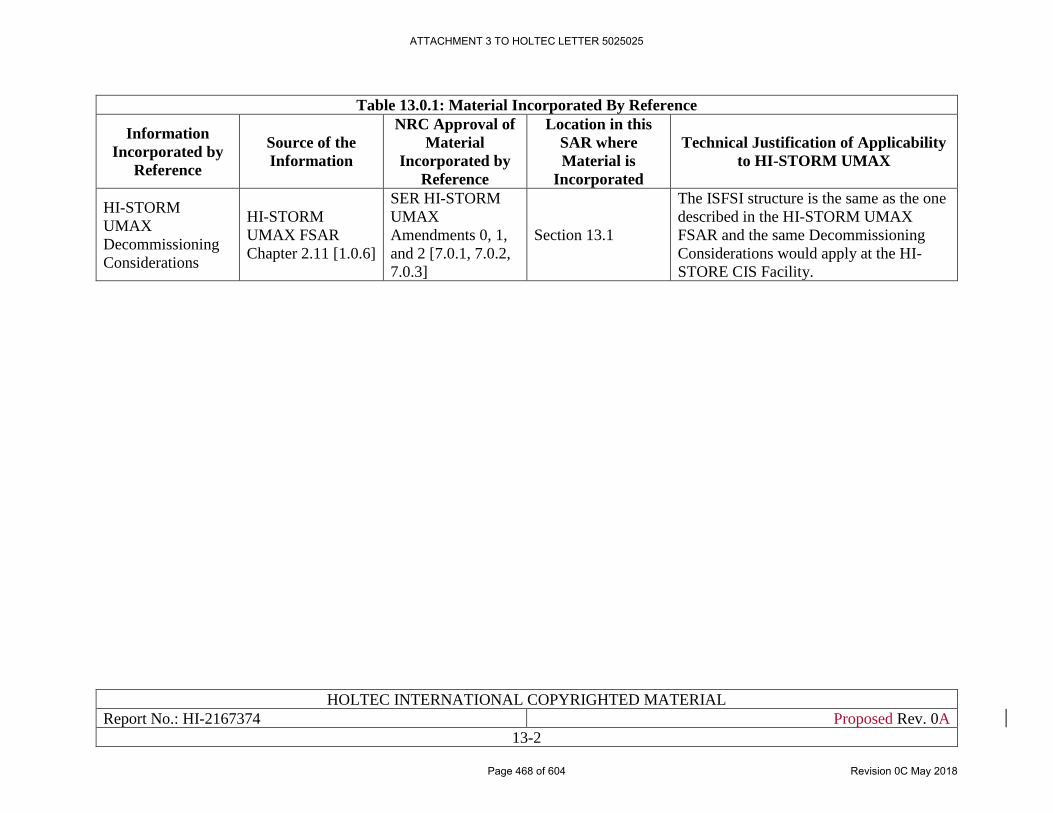
HOLTEC INTERNATIONAL COPYRIGHTED MATERIAL
Report No.: HI-2167374 Proposed Rev. 0A
13-2
Table 13.0.1: Material Incorporated By Reference
Information
Incorporated by
Reference
Source of the
Information
NRC Approval of
Material
Incorporated by
Reference
Location in this
SAR where
Material is
Incorporated
Technical Justification of Applicability
to HI-STORM UMAX
HI-STORM
UMAX
Decommissioning
Considerations
HI-STORM
UMAX FSAR
Chapter 2.11 [1.0.6]
SER HI-STORM
UMAX
Amendments 0, 1,
and 2 [7.0.1, 7.0.2,
7.0.3]
Section 13.1
The ISFSI structure is the same as the one
described in the HI-STORM UMAX
FSAR and the same Decommissioning
Considerations would apply at the HI-
STORE CIS Facility.
ATTACHMENT 3 TO HOLTEC LETTER 5025025
Page 468 of 604 Revision 0C May 2018
HOLTEC INTERNATIONAL COPYRIGHTED MATERIAL
Report No.: HI-2167374 Proposed Rev. 0A
13-3
13.1 DESIGN FEATURES
Section 2.11 of the HI-STORM UMAX FSAR [1.0.6] is incorporated by reference into this SAR,
and describes all the design features of the ISFSI which are considered for the decommissioning
of the Site. The CTF and other auxiliary SSCs, as described in Chapter 4, support decommissioning
processes similar to those used for the HI-STORM UMAX VVM structures.
ATTACHMENT 3 TO HOLTEC LETTER 5025025
Page 469 of 604 Revision 0C May 2018
HOLTEC INTERNATIONAL COPYRIGHTED MATERIAL
Report No.: HI-2167374 Proposed Rev. 0A
13-4
13.2 OPERATIONAL FEATURES
The layout and design of the HI-STORE CIS Facility will facilitate rapid, safe, and economical
decommissioning of the Site. As described in Chapter 2 of the HI-STORM UMAX FSAR [1.0.6],
the VVM components are designed to allow the retrieval of the MPC under all conditions of
storage. The MPC, which holds the SNF assemblies, is engineered to be suitable as a waste
package for permanent internment in a deep Mined Geological Disposal System (MGDS).
Towards that end, the loaded MPC has been designed with the objective to transport it in a
transportation cask, which is an a priori assumption for receipt of the canisters at the Site.
The HI-STORE CIS Facility will be operated as a “clean” facility. All components of the facility
including the transport casks and storage canisters are designed to minimize the potential for any
contamination. Canisters are already welded shut and sealed to prevent leaks at the generator
facility. All procedures controlling handling and storage operations of the canisters will emphasize
minimizing any potential contamination at the Site. Dose rate surveys will be performed
throughout the operations for site receiving and loading of canisters as discussed in Chapter 3 of
this SAR. The dose requirements for these surveys are discussed in Chapter 7 of this SAR.
Pursuant to 10 CFR 72.30(f), records of importance to the decommissioning of the HI-STORE
CIS Facility will be maintained until the site is released for unrestricted use. Records will include:
• Records of spills or other unusual occurrences involving the spread of contamination in
and around the facility, equipment, or site.
• Records on contamination that may have spread to inaccessible areas.
• As-built drawings and modifications of structures and equipment used in the storage of
radioactive materials.
• A list containing all areas designated as a restricted area.
• The decommissioning funding plan, cost estimate, and records of the funding method used
for assuring funds are available for decommissioning.
ATTACHMENT 3 TO HOLTEC LETTER 5025025
Page 470 of 604 Revision 0C May 2018
HOLTEC INTERNATIONAL COPYRIGHTED MATERIAL
Report No.: HI-2167374 Proposed Rev. 0A
13-5
13.3 DECOMMISSIONING PLAN
13.3.1 General Provisions
A Preliminary Decommissioning Plan for the HI-STORE CIS Facility is provided in Holtec Report
HI-2177558 [13.3.1]. A summary of this preliminary plan and is presented below.
The objective of decommissioning activities at the HI-STORE CIS Facility is to verify that any
potential radioactive contamination is below established release limits, and in the unlikely event
of contamination, to identify and remove radioactive contamination that is above the NRC release
limits, so that the site may be released for unrestricted use and the NRC license terminated.
Residual radioactive contamination is not anticipated at the HI-STORE CIS Facility for several
reasons:
• Canisters are surveyed and decontaminated at the generator facility, prior to shipment, to
ensure the outer surfaces are clean. This is repeated at the HI-STORE CIS Facility to ensure
dose rate and contamination requirements are met.
• Canisters are welded shut and sealed to prevent leaks.
• Canisters will not be opened during transportation to the Site or during transfer, handling,
or storage operations at any time.
• Radiological activation of the VVM and concrete pad materials is expected to be
insignificant with radiation levels below the applicable NRC criteria for unrestricted
release.
An insignificant amount of radioactive wastes are expected to be generated at the HI-STORE CIS
Facility from normal operations of the Site. Conventional decontamination techniques will be used
to minimize the volume of waste generated. Any waste generated will be sent to a licensed facility
for disposal. Gaseous and liquid wastes are not generated at the HI-STORE CIS Facility. Small
volumes of solid radioactive waste may be produced from routine operations involving
contamination surveys and decontamination activities involving incoming and outgoing
transportation casks and equipment. Potential solid waste streams are collected and temporarily
stored at the Site until offsite shipping, processing, and disposal methods are available.
A Final Decommissioning Plan detailing activities and procedures for decommissioning will be
provided once all of the canisters are removed from the facility. The Final Decommissioning Plan
will address final status survey of the site and termination of the license. The final plan will
evaluate NRC criteria for decommissioning to ensure all requirements are satisfied.
Decommissioning activities will be planned using ALARA principles and in a manner that protects
the public and environment during the process.
13.3.2 Cost Estimate
Pursuant to 10 CFR 72.30, a decommissioning cost estimate was prepared and is presented in
Holtec Report HI-2177565 [13.3.2]. This report discusses the decommissioning cost estimate and
financial funding assurance per 10 CFR 72.30(b)(2). The decommissioning cost estimate follows
the guidance of NUREG-1757 [13.3.3, 13.3.4] for activities that will allow the NRC license to be
terminated and the remaining facility and site may be released for unrestricted use.
ATTACHMENT 3 TO HOLTEC LETTER 5025025
Page 471 of 604 Revision 0C May 2018
HOLTEC INTERNATIONAL COPYRIGHTED MATERIAL
Report No.: HI-2167374 Proposed Rev. 0A
13-6
The cost estimating method used for developing the overall decommissioning cost estimate is
based on resource costing. The resource costing is based on the resources and duration to estimate
the costs associated with radiological surveys and decontamination activities. The estimated labor
costs are based on an R.S. Means 2017 [13.3.5] that will allow an independent third party to assume
the responsibility and carry out the decommissioning project. Non-labor costs include equipment
and security.
The decommissioning cost estimate is based on the following key assumptions:
• All costs associated with removing the canisters from the site is not included.
• Four crews will be used to perform the radiological survey within a one year time frame.
• No subsurface material is assumed to require remediation regarding radionuclides.
• No canisters will be opened at the CIS Facility
• Nuclear activation of the VVMs and concrete pads are anticipated to be below the release
limits, however for the purposes of the cost estimate, it is assumed that removal and
remediation of the VVMs will be necessary
• There is no subsurface soil containing residual radioactivity that will require remediation.
• The decommissioning tasks are assumed to be completed in a two year time frame.
• All costs used in the estimates were current on January 2017.
The decommissioning cost estimate will be updated a minimum of every three years, adjusting the
estimated cost for current prices of services, inflation (as necessary), and approach. The key
assumptions will be also be revisited and adjusted as warranted.
13.3.3 Financial Assurance Mechanism
The method of financial assurance as specified in 10 CFR 72.30(e)(3) will be met by Holtec
International. Expected decommissioning costs for Phase 1 of the HI-STORE CIS Facility are
presented in Holtec Report HI-2177565 [13.3.2]. A decommissioning fund will be established by
setting aside a fixed dollar amount per MTU stored at the HI-STORE facility. These funds, plus
earnings on such funds calculated at a fixed rate of return over the life of the facility, will cover
the estimated cost to complete decommissioning.
ATTACHMENT 3 TO HOLTEC LETTER 5025025
Page 472 of 604 Revision 0C May 2018
HOLTEC INTERNATIONAL COPYRIGHTED MATERIAL
Report No.: HI-2167374 Proposed Rev. 0A
13-7
13.4 REGULATORY COMPLIANCE
Pursuant to the guidance provided in NUREG-1567 [1.0.3], the foregoing material in this Chapter
provides:
i. A complete description of the Design Features of the Site which facilitate decommissioning
as mandated by 10CFR72.24, 72.30, and 72.130;
ii. A complete description of the Operational Features of the Site which facilitate
decommissioning as mandated by 10CFR72.24, 72.30, and 72.130;
iii. A complete description of the Decommissioning Plan for the Site including the
Decommissioning Cost Estimate and Decommissioning Funding Plan as mandated by
10CFR72.24, 72.30, and 72.130;
Therefore, it can be concluded that this SAR provides adequate information to assure that
decommissioning issues for the ISFSI facility have been adequately characterized, so that the site
will ultimately be available for unrestricted use for any private or public purpose. Additionally, it
can be concluded that this SAR provides adequate information to estimate the costs of
decommissioning activities as well as sufficient financial assurance mechanisms to provide
reasonable assurance that adequate funds will be available to decommission the facility so that the
site will ultimately be available for unrestricted use for any private or public purpose.
ATTACHMENT 3 TO HOLTEC LETTER 5025025
Page 473 of 604 Revision 0C May 2018
HOLTEC INTERNATIONAL COPYRIGHTED MATERIAL
Report No. 2167374 Proposed Rev. 0A
14-1
CHAPTER 14: WASTE CONFINEMENT AND MANAGEMENT
EVALUATION
14.0 INTRODUCTION
Radioactive wastes are not generated as a result of handling and storage operations for spent fuel
or high-level waste (HLW) at the HI-STORE CIS site. The canisters bearing SNF and other
approved contents for storage in HI-STORM UMAX systems at the HI-STORE CIS serves as the
confinement system during storage and related operations, as noted in Chapter 9 of this report.
There is no breaching or opening of the confinement canister during storage operations. The
integrity of the confinement system has been proven via analysis to be maintained during normal,
off-normal and hypothetical accident conditions as discussed in Chapters 9 and 15 of this report.
All references are in placed within square brackets in this report and are compiled in Chapter 19 of this report.
ATTACHMENT 3 TO HOLTEC LETTER 5025025
Page 474 of 604 Revision 0C May 2018
HOLTEC INTERNATIONAL COPYRIGHTED MATERIAL
Report No. 2167374 Proposed Rev. 0A
14-2
14.1 WASTE SOURCES
Radioactive wastes typically generated during operations at an ISFSI fall into the categories (a and
b) below. However, as discussed in Sections 14.3, 14.4 and 14.5, the HI-STORE CIS does not
generate radioactive wastes in any form during operations. Therefore, implicitly, the HI-STORE
CIS complies with the radioactive wastes and radiological impact criteria in 10CFR20 and
10CFR72, as they pertain to the waste generated onsite.
a) Effluents (gaseous and liquid), and
b) Wastes (solid or solidified)
In addition to the radioactive waste types above, NUREG-1567 [1.0.3] also recommends
evaluation of exposure of radioactive wastes to non-radioactive wastes such as combustion
products and chemical wastes.
Combustion Products
An explosion within the protected area of the ISFSI is unlikely, since explosive materials are
generally prohibited within the site boundary. However, an explosion as a result of combustible
fluid contained in the VCT is possible (Subsection 6.5.2). Due to the quantity of combustible fluid
and the structurally robust construction materials of the HI-TRAC transfer cask, HI-STORM
UMAX VVM and the canister, the effects of a fire is minimal, and the confinement boundary of
the canister is not compromised (Subsection 6.5.2). The canister is in the HI-TRAC during transfer
by the VCT to the HI-STORM UMAX VVM, which provides protection to the canister during an
explosion. The effect of an explosion on the canister is further reduced after loading into a HI-
STORM UMAX. Canisters in a HI-STORM UMAX system are protected from an explosion by
the robust lid of the HI-STORM UMAX, the ISFSI pad, the subgrade and HI-STORM UMAX
VVM. Thus explosions due to combustion products will not compromise canisterized wastes being
transferred to the VVM or in the VVM, and therefore have no radiological impact. There is also
no credible mechanism through which radioactive wastes will come into contact with the fuel prior
to or after loading into the VCT, which could potentially result in unplanned releases as exhausts
effluents from the VCT’s engine during operations.
Chemical Wastes
There are no chemical wastes generated at the HI-STORE CIS Facility.
ATTACHMENT 3 TO HOLTEC LETTER 5025025
Page 475 of 604 Revision 0C May 2018
HOLTEC INTERNATIONAL COPYRIGHTED MATERIAL
Report No. 2167374 Proposed Rev. 0A
14-3
14.2 OFF-GAS TREATMENT AND VENTILATION
The HI-STORE CIS is not a waste treatment facility. Canisters loaded and welded shut at the waste
site of origin remain closed during transfer operations and storage at the HI-STORE CIS. The
canister confinement boundary is not procedurally opened during operations upon arrival at the
HI-STORE CIS. Furthermore, upon arrival at the HI-STORE CIS and prior to opening the
transport cask containment boundary, the transport cask and the loaded canister are leak tested to
ANSI N14.5 (Subsection 10.3.3) “leaktight” criteria to ensure the confinement boundary of the
canister was not compromised during transport to the HI-STORE CIS. If a breach of the loaded
canister is detected during the leakage test, the loaded transport cask is transported off-site to a
facility authorized to perform contents unloading operations or transported back to the site of
origin of the radioactive wastes without opening its transport cask containment boundary.
Therefore, since a) breach of the confinement canisters is deemed non-credible under analyzed
conditions, b) opening of the confinement boundary of canisters is procedurally prohibited at the
HI-STORE CIS, and c) the HI-STORE CIS is not a waste treatment facility, the generation or
presence of gaseous effluents, either due to contamination cleanup or other activities is non-
credible, and negates the need for off-gas treatment and ventilation systems.
ATTACHMENT 3 TO HOLTEC LETTER 5025025
Page 476 of 604 Revision 0C May 2018
HOLTEC INTERNATIONAL COPYRIGHTED MATERIAL
Report No. 2167374 Proposed Rev. 0A
14-4
14.3 LIQUID WASTE TREATMENT AND RETENTION
The HI-STORE CIS is designed for passive storage of HI-STORM UMAX Systems that require
no further handling once canisters are loaded into the VVM. Liquid wastes, radioactive or non-
radioactive, are not generated at the HI-STORE CIS during handling and or storage operations.
Therefore treatment and retention systems for liquid wastes are not required.
Fuel and HLW loaded canisters are inspected prior to transport to the HI-STORE CIS. Upon arrival
at the HI-STORE CIS, the transport cask or overpack is inspected for damage and is also leak
tested along with the loaded canister. In the unlikely scenario that leakage is detected or damage
is observed to a degree that may compromise the long term integrity of the canister, the transport
cask with the loaded canister is returned to the waste site of origin or other authorized facility for
decontamination, which may involve a washdown, followed by canister unloading. Washdowns
or decontamination activities of the transport cask and canisters, if required, will not occur at the
HI-STORE CIS. This prevents generation of liquid radioactive or non-radioactive wastes at the
CIS. Furthermore, the CIS has no labs or other facilities that may produce liquid wastes, that may
become susceptible to contamination, radiologically or otherwise.
Furthermore, the ISFSI pads are designed to ensure drainage of rain water or other spilled liquids
away from the HI-STORM UMAX VVMs. Radioactive contamination of drained liquids from the
ISFSI pad is unlikely since all radioactive wastes onsite are in canisters. The canister design, as
approved by the NRC, precludes a breach of its steel weldment construction under all analyzed
conditions (Chapters 9 and 15) during storage in the HI-STORM UMAX systems. Therefore
leakage of radioactive material from the canisters is non-credible.
ATTACHMENT 3 TO HOLTEC LETTER 5025025
Page 477 of 604 Revision 0C May 2018
HOLTEC INTERNATIONAL COPYRIGHTED MATERIAL
Report No. 2167374 Proposed Rev. 0A
14-5
14.4 SOLID WASTES
As explained in Subsection 14.3, the liquid waste (radioactive or non-radioactive) is not generated
as a result of facility normal operations and off-normal events as defined in Chapters 9 and 15 of
this report. As such, solidified wastes – generated from liquid waste stream(s) – are not generated
at the HI-STORE CIS, and there isn’t a need for a packaging system or storage facility for
solidified wastes.
Solid radioactive wastes, are not generated at the HI-STORE CIS as a result of facility operations.
SNF and HLW stored at the CIS arrives in a canister that is transferred to the HI-STORM UMAX
VVM following inspection that ensures the integrity of the canister weldment is uncompromised.
At no time during storage and transfer operations at the CIS is the canister opened and waste
handled or treated. If breach of the canister is detected during leak testing of the transport cask and
loaded canister, the package is transported back to the site of origin or other site authorized to
handle the radioactive contents of the package for unloading and other remediation activities.
Therefore no solid radioactive wastes are generated as a result of CIS facility operations, and no
packaging and storage system is needed.
ATTACHMENT 3 TO HOLTEC LETTER 5025025
Page 478 of 604 Revision 0C May 2018
HOLTEC INTERNATIONAL COPYRIGHTED MATERIAL
Report No. 2167374 Proposed Rev. 0A
14-6
14.5 RADIOLOGICAL IMPACT OF NORMAL OPERATIONS
There are no radioactive wastes generated during normal operations of the HI-STORE CIS
Facility. The radiological impact of the HI-STORE CIS Facility is provided in Chapter 11 of this
report, and is in compliance with 10CFR20 [7.4.1] and 10CFR72 [1.0.5] effluents and dose criteria.
ATTACHMENT 3 TO HOLTEC LETTER 5025025
Page 479 of 604 Revision 0C May 2018
HOLTEC INTERNATIONAL COPYRIGHTED MATERIAL
Report No. 2167374 Proposed Rev. 0A
14-7
14.6 REGULATORY COMPLIANCE
In accordance with NUREG-1567 [1.0.3], this chapter should comply with 10CFR20 Appendix B
Table 2, 10CFR72.24(l) and (f), 10CFR72.40(a)(13), 10 CFR72.104, 72.122(h), 10 CFR 72.126(c)
and (d), and 10CFR72.128(a)(5) and (b).
10CFR20 Appendix B, Table 2 gaseous or liquid effluents radionuclide concentration limits shall
not be exceeded at the HI-STORE CIS Facility.
10CFR72.24(f) requires this report to include features of the ISFSI design and operating modes
that reduce to the extent practicable radioactive waste volumes generated at the installation.
10CFR72.24(l) requires description of instruments that maintain control over radioactive materials
in gaseous and liquid effluents produced during normal operations and expected operational
occurrences.
10CFR72.40(a)(13) requires that this report provide reasonable assurance that (i) the activities
authorized by the license can be conducted without endangering the health and safety of the public,
and (ii) the activities be conducted in compliance with applicable regulations of this chapter.
10CFR72.104 doses shall not be exceeded.
10CFR72.122(h)(3) requires that ventilation systems and off-gas systems must be provided where
necessary to ensure the confinement of airborne radioactive particulate materials during normal or
off-normal conditions.
10CFR72.126(c) requires as appropriate for handling and storage systems that effluent monitoring
system be provided, and direct radiation monitoring system be provided in and around areas
containing radioactive materials.
10CFR72.126(d) requires the ISFSI be designed to provide means to limit as low as reasonably
achievable the release of radioactive materials in effluents during normal operations; and control
the release of radioactive materials under accident conditions. Show via analysis that releases to
the environment will be within the exposure limits given in 10 CFR 72.104 for normal conditions
and 10 CFR 72.106 for design basis accident conditions.
10CFR72.128(a)(5) requires spent fuel and other radioactive wastes handling and storage systems
must be designed to minimize the quantity of radioactive wastes generated.
10CFR 72.128(b) radioactive waste treatment facilities must be provided. Provisions must be made
for the packing of site-generated low-levels wastes in a form suitable for storage onsite awaiting
transfer to disposal sites.
This chapter ensures that the HI-STORE CIS Facilities complies with the applicable waste
confinement and management regulatory requirements of 10 CFR 20 and 72. The HI-STORE CIS
Facility is designed to receive welded canisters containing SNF and related hardware. No
radioactive wastes (gaseous or liquid effluents) will be generated at the ISFSI site, and the canisters
will arrive welded and remain welded throughout the storage duration at the HI-STORE CIS ISFSI.
The canisters are classified as “leaktight” in accordance with ANSI N14.5 (Subsection 10.3.3),
and release to the environment or impact on public health and safety is considered non credible or
negligible. Therefore no effluents monitoring system are provided. Radiation monitoring
ATTACHMENT 3 TO HOLTEC LETTER 5025025
Page 480 of 604 Revision 0C May 2018
HOLTEC INTERNATIONAL COPYRIGHTED MATERIAL
Report No. 2167374 Proposed Rev. 0A
14-8
equipment are provided at the HI-STORE CIS Facility as discussed in the Radiation Protection
chapter (11).
As noted in Section 2.2 of this report, four nuclear facilities exist or are planned to be built within
50 miles of the proposed site for the HI-STORE CIS Facility. The closest nuclear facility is located
16 miles southwest of the proposed site for the HI-STORE CIS Facility. As such, there is no
concern of the cumulative impact from operation of the HI-STORE CIS Facility and nearby
facilities on the public. The environmental impacts of other nuclear facilities are in impact
statements in Section 2.2 of this report.
ATTACHMENT 3 TO HOLTEC LETTER 5025025
Page 481 of 604 Revision 0C May 2018
HOLTEC INTERNATIONAL COPYRIGHTED MATERIAL
Report No.: HI-2167374 Proposed Rev. 0A
15-1
CHAPTER 15: ACCIDENT ANALYSIS1
15.0 INTRODUCTION
This chapter is focused on the safety evaluation of all off-normal and accident events germane to
the HI-STORE CIS facility. For each postulated event, the event cause, means of detection,
consequences, and corrective actions, as applicable, are discussed and evaluated. For other
miscellaneous events (i.e., those not categorized as either design basis off-normal or accident
condition events), a similar outline for safety analysis is followed. As applicable, the evaluation of
consequences includes the impact on the structural, thermal, shielding, criticality, confinement,
and radiation protection performance of the system due to each postulated event.
As the HI-STORE facility deploys the NRC licensed HI-STORM UMAX System for long term
storage of spent fuel the applicable off-normal and accident events addressed in the HI-STORM
UMAX FSAR [1.0.6] are incorporated herein by reference. A roadmap of applicable HI-STORM
UMAX material is tabulated in Table 15.0.1.
The structural, thermal, shielding, criticality, and confinement features and performance of the HI-
STORM UMAX system under the short-term operations and various conditions of storage are
discussed in Chapters 5, 6, 7, 8 and 9. The evaluations provided in this chapter are based on the
safety analyses reported therein. The accidents considered in this chapter follow guidance in
NUREG-1567 [1.0.3] and NUREG-1536 [15.3.1].
1 All references are in placed within square brackets in this report and are compiled in Chapter 19 (last chapter).
ATTACHMENT 3 TO HOLTEC LETTER 5025025
Page 482 of 604 Revision 0C May 2018
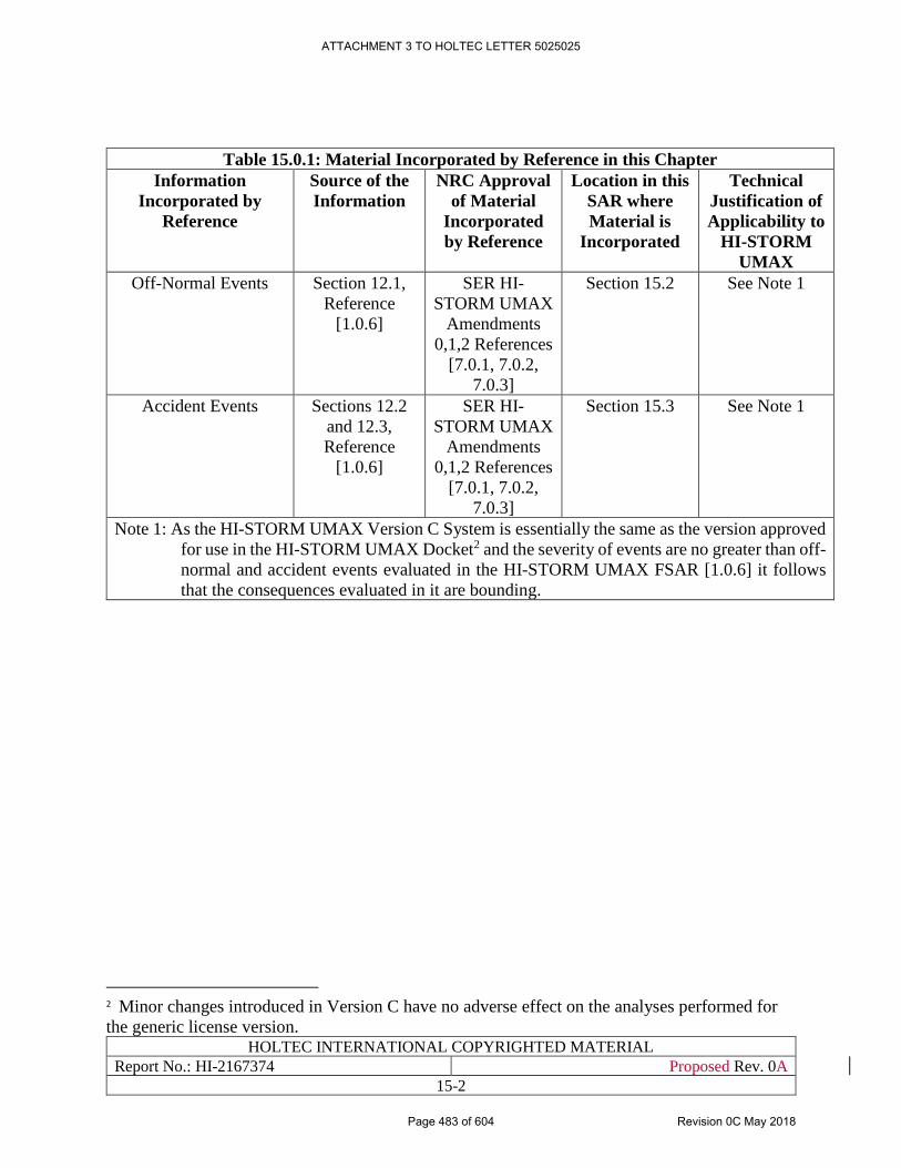
HOLTEC INTERNATIONAL COPYRIGHTED MATERIAL
Report No.: HI-2167374 Proposed Rev. 0A
15-2
Table 15.0.1: Material Incorporated by Reference in this Chapter
Information
Incorporated by
Reference
Source of the
Information
NRC Approval
of Material
Incorporated
by Reference
Location in this
SAR where
Material is
Incorporated
Technical
Justification of
Applicability to
HI-STORM
UMAX
Off-Normal Events Section 12.1,
Reference
[1.0.6]
SER HI-
STORM UMAX
Amendments
0,1,2 References
[7.0.1, 7.0.2,
7.0.3]
Section 15.2 See Note 1
Accident Events Sections 12.2
and 12.3,
Reference
[1.0.6]
SER HI-
STORM UMAX
Amendments
0,1,2 References
[7.0.1, 7.0.2,
7.0.3]
Section 15.3 See Note 1
Note 1: As the HI-STORM UMAX Version C System is essentially the same as the version approved
for use in the HI-STORM UMAX Docket2 and the severity of events are no greater than off-
normal and accident events evaluated in the HI-STORM UMAX FSAR [1.0.6] it follows
that the consequences evaluated in it are bounding.
2 Minor changes introduced in Version C have no adverse effect on the analyses performed for
the generic license version.
ATTACHMENT 3 TO HOLTEC LETTER 5025025
Page 483 of 604 Revision 0C May 2018
HOLTEC INTERNATIONAL COPYRIGHTED MATERIAL
Report No.: HI-2167374 Proposed Rev. 0A
15-3
15.1 ACCEPTANCE CRITERIA
15.1.1 Off-Normal Events
Criticality
In accordance with 10CFR72.124(a) regulations spent fuel sub-criticality must be maintained with
keff equal to or less than 0.95.
Confinement
In accordance with 10CFR72.128(a)(3) regulations systems important to safety must be evaluated
to reasonably ensure radioactive material remains confined under off-normal and accident events.
Retrievability
In accordance with 10CFR72.122(l) storage systems must allow safe retrieval of the stored spent
fuel without endangering public health and safety or undue exposure to workers.
Instrumentation
In accordance with 10 CFR72.122(i) and 72.128(a)(1) the SAR must identify all instruments and
control systems required to remain operational under accident conditions.
15.1.2 Accident Events
In addition to Subsection 15.1.1 criteria, dose rates to individuals located at or beyond controlled
area boundary must meet 10CFR72.106(b) limits under design basis accidents.
ATTACHMENT 3 TO HOLTEC LETTER 5025025
Page 484 of 604 Revision 0C May 2018
HOLTEC INTERNATIONAL COPYRIGHTED MATERIAL
Report No.: HI-2167374 Proposed Rev. 0A
15-4
15.2 OFF-NORMAL EVENTS
In this section, design events pertaining to off-normal operation under expected operational
occurrences are considered and evaluated.
The following off-normal events are applicable to the HI-STORE CIS facility:
• Off-Normal Pressure
• Off-Normal Environmental Temperature
• Leakage of One MPC Seal
• Partial Blockage of Air Inlet and Outlet Ducts
• Hypothetical Non-Quiescent Wind3
• Cask Drop Less Than Design Allowable Height
• Off-Normal Events Associated with Pool Facilities
15.2.1 Off-Normal Pressure
The sole pressure boundary in the HI-STORM UMAX storage System is the MPC enclosure
vessel. The off-normal pressure condition is specified in Section 6.4 and evaluated in Section 6.5.
The off-normal pressure for the MPC internal cavity is a function of the initial helium fill pressure
and the steady state temperature reached within the MPC cavity under normal ambient
temperature. The MPC internal pressure under the off-normal condition is evaluated with 10% of
the fuel rods ruptured and with 100% of ruptured rods fill gas and 30% of ruptured rods fission
gases released to the cavity.
15.2.1.1 Postulated Cause of Off-Normal Pressure
Fuel rods rupture is a non-mechanistic event postulated as a defense-in-depth measure and
evaluated.
15.2.1.2 Detection of Off-Normal Pressure
The HI-STORM UMAX system is designed to withstand the MPC off-normal internal pressure
without any effects on its ability to meet its safety requirements. There is no requirement or safety
imperative for detection of off-normal pressure and, therefore, no monitoring is required.
15.2.1.3 Analysis of Effects and Consequences of Off-Normal Pressure
The MPC off-normal internal pressure is analyzed in Section 6.4. The analysis shows that the MPC
pressure remains below Off-Normal limit.
i. Structural
Structural integrity of the MPC enclosure vessel is not affected as the pressure computed
under this event remains below the MPC Off-Normal pressure limit as qualified by the
3 Hypothetical non-quiescent wind intends to evaluate HI-STORM UMAX under a sustained persistent wind of a
constant magnitude and direction to maximize disruption of the thermal performance.
ATTACHMENT 3 TO HOLTEC LETTER 5025025
Page 485 of 604 Revision 0C May 2018
HOLTEC INTERNATIONAL COPYRIGHTED MATERIAL
Report No.: HI-2167374 Proposed Rev. 0A
15-5
structural design of the MPC in Section 3.1 of the HI-STORM UMAX FSAR [1.0.6] and
incorporated herein by reference.
ii. Thermal
The MPC internal pressure under off-normal conditions is evaluated in Section 6.5. The
computed pressure remains below Off-Normal pressure limit.
iii. Shielding
There is no effect on the shielding performance of the system as a result of this off-normal
event.
iv. Criticality
There is no effect on the criticality control features of the system as a result of this off-
normal event.
v. Confinement
There is no effect on the confinement function of the MPC as a result of this off-normal
event. As discussed in the structural evaluation above, all pressure boundary stresses
remain within allowable ASME Code values, assuring Confinement Boundary integrity.
vi. Radiation Protection
As shielding and confinement functions are not affected as evaluated above, there is no
adverse effect on occupational or public exposures as a result of this off-normal event.
15.2.1.4 Corrective Action for Off-Normal Pressure
The HI-STORM UMAX system is designed to withstand the off-normal pressure without any
effects on its ability to maintain safe storage conditions. Therefore, there is no corrective action
requirement for off-normal pressure.
15.2.1.5 Radiological Impact of Off-Normal Pressure
The event of off-normal pressure has no radiological impact because the confinement barrier and
shielding integrity are not affected.
15.2.1.6 Conclusion
Based on this evaluation, it is concluded that the off-normal pressure does not affect the safe
operation of the HI-STORM UMAX system.
15.2.2 Off-Normal Environmental Temperature
As evaluated in Subsection 6.5.1 this event is bounded by HI-STORM UMAX FSAR [1.0.6].
Event evaluation incorporated by reference. See Table 15.0.1 and HI-STORM UMAX FSAR
Subsection 12.1.2 [1.0.6].
15.2.3 Leakage of one MPC seal
The MPC confinement boundary is defined by MPC shell, baseplate, lid, vent and drain port
covers, closure ring and associated welds. Leakage of an MPC seal weld evaluated in HI-STORM
UMAX FSAR Subsection 12.1.3 [1.0.6] is incorporated by reference.
ATTACHMENT 3 TO HOLTEC LETTER 5025025
Page 486 of 604 Revision 0C May 2018
HOLTEC INTERNATIONAL COPYRIGHTED MATERIAL
Report No.: HI-2167374 Proposed Rev. 0A
15-6
15.2.4 Partial Blockage of the Air Inlet and Outlet Ducts
As evaluated in Subsection 6.5.1 this event is bounded by HI-STORM UMAX FSAR [1.0.6].
Event evaluation incorporated by reference. See Table 15.0.1 and HI-STORM UMAX FSAR
Subsection 12.1.4 [1.0.6].
15.2.5 Hypothetical Non-Quiescent Wind
As evaluated in Subsection 6.4.3 this event is bounded by HI-STORM UMAX FSAR [1.0.6].
Event evaluation incorporated by reference. See Table 15.0.1 and HI-STORM UMAX FSAR
Subsection 12.1.5 [1.0.6].
15.2.6 Cask Drop Less Than Design Allowable Height
HI-STORM UMAX VVM
Not applicable as HI-STORM UMAX VVM is a permanently installed underground structure.
HI-TRAC CS
HI-TRAC CS drop not credible as heavy load handling requires redundant drop protection. See
Chapter 4, Subsections 4.5.1, 4.5.2 and 4.5.3.
HI-STAR 190
HI-STAR 190 drop not credible as heavy load handling requires redundant drop protection. See
Chapter 4, Subsections 4.5.1, 4.5.2 and 4.5.3.
15.2.7 Off-Normal Events Associated with Pool Facilities
Not applicable to HI-STORE CIS facility as pool facilities not required to support operations.
15.2.8 Safety Evaluation
Off-Normal event analyses support the conclusion that HI-STORM UMAX robustly withstands
impact of off-normal events and complies with Section 15.1 Acceptance Criteria and Chapter 4
Design Limits.
ATTACHMENT 3 TO HOLTEC LETTER 5025025
Page 487 of 604 Revision 0C May 2018
HOLTEC INTERNATIONAL COPYRIGHTED MATERIAL
Report No.: HI-2167374 Proposed Rev. 0A
15-7
15.3 ACCIDENTS
Accidents, in accordance with ANSI/ANS-57.9 [2.7.2], are either infrequent events that could
reasonably be expected to occur during the lifetime of the cask or events postulated because their
consequences may affect public health and safety. Accidents germane to the safety evaluation of
HI-STORM UMAX system are considered and evaluated herein.
The following accident events are applicable to the HI-STORE CIS facility:
• Fire Accident
• Partial Blockage of MPC Basket Vent Holes
• Tornado Missiles
• Flood
• Earthquake
• 100% Fuel Rods Rupture
• Confinement Boundary Leakage
• Explosion
• Lightning
• 100% Blockage of Air Inlet and Outlet Ducts
• Burial Under Debris
• Extreme Environmental Temperature
• Cask Tipover
• Cask Drop
• Loss of Shielding
• Adiabatic Heatup
• Accidents at Nearby Sites
• Accidents Associated with Pool Facilities
• Building Structural Failure onto SSCs
• 100% Rod Rupture Accident Coincident with Accident Events
15.3.1 Fire Accident
The potential of a fire accident is extremely remote by ensuring that there are no significant
combustible materials in the area. The only credible concern is related to a transport vehicle fuel
tank fire engulfing a loaded HI-STORM UMAX VVM or a HI-TRAC CS transfer cask. Fire
accident involving the HI-STORM UMAX VVM, HI-TRAC CS or HI-STAR 190 fire is evaluated
in the following.
ATTACHMENT 3 TO HOLTEC LETTER 5025025
Page 488 of 604 Revision 0C May 2018
HOLTEC INTERNATIONAL COPYRIGHTED MATERIAL
Report No.: HI-2167374 Proposed Rev. 0A
15-8
15.3.1.1 Fire Analysis
(a) HI-STORM UMAX VVM Fire
The analysis for the fire accident including the methodology is articulated in Subsection 6.5.2. The
transport vehicle fuel tank fire is analyzed to evaluate the storage overpack heating by the incident
thermal radiation and forced convection heat fluxes and fuel cladding and MPC temperatures.
i. Structural
As evaluated in Subsection 6.5.2 there are no structural consequences of the fire accident
condition as the short-term temperature limit on great majority of the concrete is not
exceeded and component temperatures remain within Chapter 4 temperature limits. The
MPC structural boundary remains within normal condition internal pressure and
temperature limits.
ii. Thermal
Based on a conservative analysis articulated in Subsection 6.5.2 and computed response
under the hypothetical event, it is concluded that the fire event does not affect the
temperature of the MPC or contained fuel. Furthermore, the ability of the HI-STORM
UMAX System to maintain cooling of the spent nuclear fuel within temperature limits
during and after fire is not compromised.
iii. Shielding
With respect to limited damage to the outer layers of concrete subject to direct fire flux,
NUREG-1536 (4.0,V,5.b) states: “the loss of a small amount of shielding material is not
expected to cause a storage system to exceed the regulatory requirements in 10 CFR 72.106
and, therefore, need not be estimated or evaluated in the FSAR.”
iv. Criticality
There is no effect on the criticality control features of the system as a result of this event.
v. Confinement
There is no effect on the confinement function of the MPC as a result of this event as the
structural integrity of the confinement boundary is unaffected.
vi. Radiation Protection
As there is minimal reduction, if any, in shielding and no effect on the confinement
capabilities as discussed above, there is no effect on occupational or public exposures as a
result of this accident event.
As supported by evaluation above, it is concluded that the design basis fire does not affect the safe
operation of the HI-STORM UMAX System.
(b) HI-TRAC CS Fire
The HI-TRAC CS must withstand elevated temperatures under the Design Basis Fire event defined
Chapter 6. The acceptance criteria for the fire accident are specified in Design Criteria Chapter 4.
i. Structural
ATTACHMENT 3 TO HOLTEC LETTER 5025025
Page 489 of 604 Revision 0C May 2018
HOLTEC INTERNATIONAL COPYRIGHTED MATERIAL
Report No.: HI-2167374 Proposed Rev. 0A
15-9
The effect of the fire accident on the HI-TRAC CS is an increase in fuel cladding and
system component temperatures and MPC internal pressure and thus an increase in MPC
pressure boundary stresses. The resultant temperatures and pressures are below the
accident design limits as evaluated below. The MPC pressures resulting from the fire
accident event are be bounded by the applicable pressure boundary limits; therefore, there
is no effect on structural function.
ii. Thermal
As evaluated in Section 6.5, the effect of the fire does not result in any system component
or the contained fuel to exceed temperature limits set in this SAR. The Design Basis Fire
has a minor impact on MPC pressure. The temperatures and pressures resulting from the
fire accident event are to be bounded by the applicable system temperature and pressure
limits; therefore, there is no deleterious effect on the system’s thermal function. With
respect to limited damage to the outer layers of concrete subject to direct fire flux, NUREG-
1536 (4.0,V,5.b) states: “the loss of a small amount of shielding material is not expected to
cause a storage system to exceed the regulatory requirements in 10 CFR 72.106 and,
therefore, need not be estimated or evaluated in the FSAR.”
iii. Shielding
Under the fire accident condition, the outside of the cask would heat up significantly, and
while the outer steel shell would assure the overall integrity of the cask, and hence prevent
any significant loss of shielding function, the outer area of the shielding concrete may
experience some degradation. To model this in an analysis, shielding calculations are
performed in which the density of the HI-TRAC CS concrete is substantially degraded as
shown in Table 7.3.1. Results of the analyses are presented in Table 7.4.4, demonstrating
compliance with 10CFR72.106.
iv Criticality
There is no effect on the criticality control features of the system as a result of this event.
v. Confinement
There is no effect on the confinement function of the MPC as a result of this event as the
structural integrity of the confinement boundary is unaffected.
vi. Radiation Protection
There is no effect on the confinement capabilities as evaluated above, and the site boundary
shielding accident dose limits in 10CFR72.106 are not exceeded thereby ensuring
occupational and public safety.
(c) HI-STAR 190 Fire
As evaluated in Subsection 6.5.2 HI-STAR 190 fire accident under HI-STORE CIS deployment is
bounded by the HI-STAR 190 SAR transport fire accident [1.3.6]. The accident Section 3.4 is
incorporated by reference.
ATTACHMENT 3 TO HOLTEC LETTER 5025025
Page 490 of 604 Revision 0C May 2018
HOLTEC INTERNATIONAL COPYRIGHTED MATERIAL
Report No.: HI-2167374 Proposed Rev. 0A
15-10
15.3.1.2 Fire Accident Corrective Actions
Upon detection of a fire appropriate fire protection actions are initiated in accordance with facility
Emergency Response Plan [10.5.1] to extinguish the fire. Following the termination of the fire, a
visual and radiological inspection of the equipment shall be performed.
If damage to HI-STORM UMAX VVM, HI-TRAC CS or HI-STAR 190 warrant, and/or
radiological conditions require (based on dose rate measurements), the MPC shall be transferred
to HI-TRAC CS in accordance with procedures set down in Chapter 3. The HI-STORM UMAX
VVM, HI-TRAC CS or HI-STAR 190 may be returned to service after appropriate restoration
(reapplication of coatings, etc.) and if there is no significant increase in the measured dose rates
(i.e., the shielding effectiveness of overpack is confirmed) and if visual inspection is satisfactory.
15.3.1.3 Conclusion
Based on the above evaluation, it is concluded that the Design Basis Fire accident does not affect
the safe operation of the HI-STORM UMAX, HI-TRAC CS and HI-STAR 190 casks.
15.3.2 Partial Blockage of MPC Basket Vent Holes
Event evaluation incorporated by reference. See Table 15.0.1 and UMAX FSAR Subsection
12.2.2.
15.3.3 Tornado Missiles
HI-STORM UMAX VVM
Site specific tornado hazards are identified in Chapter 2, Section 2.3. These hazards are bounded
by HI-STORM UMAX FSAR [1.0.6] as justified in Chapter 4, Table 4.3.1. Accordingly, HI-
STORM UMAX FSAR tornado accident Subsection 12.2.3 [1.0.6] is incorporated by reference.
HI-TRAC CS
See discussion below.
HI-STAR 190
HI-STAR 190 damage from tornado missile impacts are bounded by the more onerous 1-meter
puncture drop accident evaluated in the HI-STAR 190 SAR [1.3.6].
15.3.3.1 Cause
Tornado and high winds are principally caused by the uneven heating of the earth’s atmosphere,
coupled with gravitational forces and the rotation of the earth. The HI-TRAC CS involves
deployment in an open area environment and thus will be subject to extreme environmental
conditions throughout the storage period.
15.3.3.2 Tornado Analysis
A tornado event is characterized by high wind velocities and tornado-generated missiles. The
reference missiles considered in this SAR are of three sizes: small, medium, and large. A small
projectile, upon collision with a cask, would tend to penetrate it. A large projectile, such as an
automobile, on the other hand, would tend to cause deformation.
ATTACHMENT 3 TO HOLTEC LETTER 5025025
Page 491 of 604 Revision 0C May 2018
HOLTEC INTERNATIONAL COPYRIGHTED MATERIAL
Report No.: HI-2167374 Proposed Rev. 0A
15-11
The tornado analysis for a HI-TRAC CS transfer cask is evaluated in Chapter 5. The evaluation is
summarized below.
i. Structural
There is no effect on the structural function of HI-TRAC CS as a result of this accident
event.
ii. Thermal
There is no effect on the function of HI-TRAC CS heat transfer features as a result of this
accident event. Tornado borne missile may cause localized damage. Global heat dissipation
characteristics are unaffected.
iii. Shielding
Tornado borne missile may cause localized damage. Dose consequences of the localized
damage are bounded by accident analysis in Shielding Chapter 7
iv. Criticality
There is no effect on the criticality control features of the MPC as a result of this accident
event.
v. Confinement
There is no effect on the confinement function of the MPC as a result of this accident event.
15.3.3.3 Radiation Protection and Consequences
There is no adverse effect on confinement functions. Controlled area boundary accident dose limits
in 10CFR72.106 are not exceeded.
15.3.3.4 Tornado Accident Corrective Action
Following a tornado accident visual and radiological inspection shall be performed in accordance
with site Emergency Response Plan and appropriate restoration measures undertaken if localized
damage results in a significant increase in measured dose.
15.3.3.5 Conclusion
Based on the above evaluation, it is concluded that the Design Basis tornado accident will not
affect the safe operation of the HI-STORM UMAX, HI-TRAC CS and HI-STAR 190 casks.
15.3.4 Flood
Site specific flood hazards are identified in Chapter 2, Section 2.4.3. These hazards are bounded
by HI-STORM UMAX FSAR [1.0.6] as justified in Chapter 4, Table 4.3.1. Moderator exclusion
under flood accident is evaluated in Chapter 8. HI-STORM UMAX FSAR flood accident
Subsection 12.2.4 [1.0.6] is incorporated by reference.
15.3.5 Earthquake
ATTACHMENT 3 TO HOLTEC LETTER 5025025
Page 492 of 604 Revision 0C May 2018
HOLTEC INTERNATIONAL COPYRIGHTED MATERIAL
Report No.: HI-2167374 Proposed Rev. 0A
15-12
HI-STORM UMAX
Site specific earthquake hazards are identified in Chapter 4, Subsection 4.3.2. These hazards are
bounded by HI-STORM UMAX FSAR [1.0.6] as justified in Chapter 4, Table 4.3.1. HI-STORM
UMAX FSAR earthquake accident Subsection 12.2.5 [1.0.6] is incorporated by reference.
HI-TRAC CS
See discussion below.
HI-STAR 190
HI-STAR 190 g-loads under earthquake events are reasonably bounded by the 10CFR Part 71 10-
meter drop accident evaluated in the HI-STAR 190 SAR [1.3.6]. In addition, the seismic stability
of freestanding HI-STAR 190 under site specific earthquake is evaluated in Chapter 5.
15.3.5.1 Cause of Event
Earthquake is a terrestrial instability event cause by relative movements in the mantle of the earth.
The only concern is under a stack up of HI-TRAC CS in the CTB during canister transfer
operations. This event is analyzed under site earthquake loading in Chapter 5 and evaluated below.
15.3.5.2 Analysis of the Effect of Site-Specific Earthquake
i. Structural
The stack-up scenario of the HI-TRAC CS has been fully evaluated in Chapter 5. Due to
the robust configuration of the HI-TRAC CS and its earthquake resistant bolting design, it
has been demonstrated that there are no structural concerns with the HI-TRAC CS under
an earthquake event.
ii. Thermal
There is no effect on the function of HI-TRAC CS heat transfer features as a result of this
accident event because no constriction of the air flow passages within the system is
computed to occur and vertical configuration is not compromised as evaluated in the
structural analysis above. Thus, the cooling effectiveness of the HI-TRAC CS remains
undiminished in under an earthquake event.
iii. Shielding
There is no adverse effect on the function of shielding features of the system as a result of
this accident event.
iv. Criticality
There is no effect on the criticality control features of the MPC as a result of this accident
event.
v. Confinement
ATTACHMENT 3 TO HOLTEC LETTER 5025025
Page 493 of 604 Revision 0C May 2018
HOLTEC INTERNATIONAL COPYRIGHTED MATERIAL
Report No.: HI-2167374 Proposed Rev. 0A
15-13
There is no effect on the confinement function of the MPC as a result of this accident event.
Structural evaluation shows stresses remain within design criteria, assuring confinement
boundary integrity.
vi. Radiation Protection and Consequences
As there is no effect on shielding or confinement functions as evaluated above, there is no
radiological consequence (from effluents and direct radiation) as a result of this accident
event. A minor increase to occupational exposures for the performance of corrective
actions is expected.
15.3.5.3 Earthquake Accident Corrective Action
Following a seismic event HI-TRAC CS must be inspected for localized damage. Visual inspection
shall be performed as follows:
• Visual inspection to confirm the extent of damage (if any) to the MPC shell is negligible.
• Visual inspection to verity the extent of damage (if any) to HI-TRAC CS components
important-to-safety is negligible.
• Visual inspection to confirm air flow passages are clear of obstructions.
Corrective actions shall be implemented based on the results of the inspection.
15.3.5.4 Conclusion
Based on the above evaluation, it is concluded that the Design Basis Earthquake will not affect the
safe operation of HI-TRAC CS. Corrective actions may be necessary to restore the system to the
pre-seismic condition.
15.3.6 100% Fuel Rods Rupture
The rupture of every fuel rod inside the Canister is postulated as a non-mechanistic event in
NUREG -1536 [15.3.1]. In other words, simultaneous failure of all fuel rods in a Canister is a
counter-factual event whose actuation mechanism cannot be articulated but it is nevertheless
postulated to ascertain the robustness of the Confinement boundary. (A similar non-credible event
requiring safety assessment in NUREG-1536 is the "non-mechanistic tip-over" of above-ground
storage casks). Because the rods are assumed to have failed a' priori, the 100% rod rupture event
does not require satisfaction of a specific fuel cladding temperature limit. Rather, the acceptance
criterion focuses on demonstrating the integrity of the Confinement Boundary. This accident is
analyzed in Subsection 6.4.3 and integrity of the Canister's pressure boundary evaluated to ensure
the internal pressure in the Canister remains below the Chapter 4 accident design pressure.
From a thermal perspective 100% percent rod rupture event is not adverse to heat transfer because
internal convection heat transfer in the Canister is significantly boosted by the release of the
plenum gases in the rods (due to their rupture), thus spatial temperature field in the Canister is
moderated (reduced in magnitude).
15.3.7 Confinement Boundary Leakage
ATTACHMENT 3 TO HOLTEC LETTER 5025025
Page 494 of 604 Revision 0C May 2018
HOLTEC INTERNATIONAL COPYRIGHTED MATERIAL
Report No.: HI-2167374 Proposed Rev. 0A
15-14
Event evaluation incorporated by reference. See Table 15.0.1 and HI-STORM UMAX FSAR
Subsection 12.2.7 [1.0.6].
15.3.8 Explosion
Accident event is bounded by HI-STORM UMAX FSAR [1.0.6]. See site specific explosion
evaluation in Chapter 4, Table 4.3.1 and Chapter 6, Subsection 6.5.2. HI-STORM UMAX FSAR
explosion accident Subsection 12.2.8 [1.0.6] is incorporated by reference.
15.3.9 Lightning
Event evaluation incorporated by reference. See Table 15.0.1 and HI-STORM UMAX FSAR
Subsection 12.2.9 [1.0.6].
15.3.10 100% Blockage of Air Inlets
Event evaluation incorporated by reference. See Table 15.0.1 and HI-STORM UMAX FSAR
Subsection 12.2.10 [1.0.6].
15.3.11 Burial Under Debris
HI-STORM UMAX
As evaluated in Chapter 6, Subsection 6.5.2 burial accident is not credible.
HI-TRAC CS
See Subsection 15.3.19.
15.3.12 Extreme Environmental Temperature
This event is bounded by the HI-STORM UMAX FSAR [1.0.6] as the site extreme ambient
temperature and cask heat loads are bounded by HI-STORM UMAX (See Table 6.3.1).
Accordingly the event evaluation is incorporated by reference. See Table 15.0.1 and HI-STORM
UMAX FSAR Subsection 12.2.12 [1.0.6].
15.3.13 Tip-over
Because the HI-STORM UMAX VVM is situated underground, a tip-over event is not a credible
accident for this design. See Table 4.3.1.
HI-TRAC CS cask and HI-STAR 190 cask tip-over is not credible as demonstrated in Chapter 5.
15.3.14 Cask Drop
HI-STORM UMAX VVM
Not applicable as HI-STORM UMAX VVM is a permanently installed underground structure.
HI-TRAC CS
HI-TRAC CS drop not credible as heavy load handling requires redundant drop protection. See
Chapter 4, Subsections 4.5.1, 4.5.2 and 4.5.3.
ATTACHMENT 3 TO HOLTEC LETTER 5025025
Page 495 of 604 Revision 0C May 2018
HOLTEC INTERNATIONAL COPYRIGHTED MATERIAL
Report No.: HI-2167374 Proposed Rev. 0A
15-15
HI-STAR 190
HI-STAR 190 drop not credible as heavy load handling requires redundant drop protection. See
Chapter 4, Subsections 4.5.1, 4.5.2 and 4.5.3.
15.3.15 Loss of Shielding
Loss of shielding rendered not-credible under an array of challenging off-normal and accident
events wherein shielding function is concluded to result in no-impact.
15.3.16 Adiabatic Heat-up
Accident not credible as this requires a counter-factual postulate choking all means of heat
dissipation including conduction, convection and radiation.
15.3.17 Accidents at Nearby Sites
To ensure HI-STORE CIS facility is not under undue risk from off-site facilities the surrounding
area must be assessed for potential hazards such as military installations, gas and oil processing or
storage facilities, oil or gas pipelines, chemicals, fireworks or explosives factories.
A survey of surrounding areas evaluated in Sections 2.1 and 2.2 yields one fire hazard that warrants
attention. The fire hazard is evaluated in Section 6.5 concluding no adverse effect on the HI-
STORM UMAX storage casks or on-site transfer operations involving the HI-TRAC CS and HI-
STAR 190.
15.3.18 Accidents Associated with Pool Facilities
Not applicable to HI-STORE CIS as pool facilities not required to support operations.
15.3.19 Building Structural Failure onto SSCs
15.3.19.1 Cause of Building Collapse
This accident is defined as a postulated structural collapse of CTB building roof and burial under
it of canister bearing HI-TRAC CS and HI-STAR 190 casks. The event is analyzed in Section 5.4
and Section 6.5, for structural and thermal considerations, respectively.
15.3.19.2 Building Collapse Analysis
Burial of casks under debris adversely affects ventilation cooling because debris will block the
inflow of air. A thermal analysis is undertaken in Section 6.5 to compute steady state maximum
cask temperatures and co-incident MPC pressures. The results are evaluated below.
i. Structural
The effect of burial under collapsed debris on the MPC is an increase in component and
fuel cladding temperatures and internal pressure and thus an increase in pressure boundary
stresses. The resultant temperatures and pressures obtained in Subsection 6.5.2 remain
below accident limits. In addition, the HI-TRAC CS and HI-STAR 190 casks are
structurally analyzed to evaluate the damage due to a potential building collapse in Section
5.4.
ii. Thermal
ATTACHMENT 3 TO HOLTEC LETTER 5025025
Page 496 of 604 Revision 0C May 2018
HOLTEC INTERNATIONAL COPYRIGHTED MATERIAL
Report No.: HI-2167374 Proposed Rev. 0A
15-16
The fuel cladding and MPC integrity is evaluated in Section 6.5. The evaluation supports
the conclusion that fuel cladding and confinement function of the MPC is not
compromised.
iii. Shielding
HI-TRAC CS
The thermal results support the conclusion there is no material loss in the shielding capacity
of the HI-TRAC CS cask.
HI-STAR 190
Limited reduction in shielding effectiveness is possible as Holtite neutron shield
temperature limits are nominally exceeded. These effects are reasonably bounded by
Holtite loss under the 10CFR Part 71 fire accident evaluated in HI-STAR 190 SAR [1.3.6].
iv. Criticality
Criticality control function is not affected under this event.
v. Confinement
Confinement function is not affected under this event.
vi. Radiation Protection and Consequences
As shielding and confinement functions as evaluated above are not affected, there is no
radiological consequence. A negligible-to-minor increase to occupational exposures for the
performance of corrective actions is expected.
15.3.19.3 Corrective Action
Analysis of building collapse accident shows that fuel, components and MPC pressures remain
below accident limits. Under building collapse accident, operator shall remove the debris from
around loaded casks in accordance with facility Emergency Response Plan [10.5.1]. Upon debris
removal flow passages shall be visually inspected to verify air flow path is free of obstructions.
The site’s emergency action plan shall include provisions for the implementation of this corrective
action.
15.3.19.4 Conclusion
Based on the above evaluation, it is concluded that the burial-under-debris accident event does not
affect the safe operation of canister bearing casks in the CTB.
15.3.20 100% Rod Rupture Accident Coincident with Accident Events
The rupture of every fuel rod inside the Canister is postulated as a non-mechanistic event in
NUREG -1536 [15.3.1]. In other words, simultaneous failure of all fuel rods in a Canister is a
counter-factual event whose actuation mechanism cannot be articulated but it is nevertheless
postulated to ascertain the robustness of the Confinement boundary. (A similar non-credible event
requiring safety assessment in NUREG-1536 is the "non-mechanistic tip-over" of above-ground
storage casks). Because the rods are assumed to have failed a' priori, the 100% rod rupture event
does not require satisfaction of a specific fuel cladding temperature limit. Rather, the acceptance
ATTACHMENT 3 TO HOLTEC LETTER 5025025
Page 497 of 604 Revision 0C May 2018
HOLTEC INTERNATIONAL COPYRIGHTED MATERIAL
Report No.: HI-2167374 Proposed Rev. 0A
15-17
criterion focuses on demonstrating the integrity of the Confinement Boundary. The integrity of the
Canister's pressure boundary is satisfied if the internal pressure in the Canister remains below the
Chapter 4 accident design pressure.
From a thermal perspective 100% percent rod rupture event is not adverse to heat transfer because
internal convection heat transfer in the Canister is significantly boosted by the release of the
plenum gases in the rods (due to their rupture), thus spatial temperature field in the Canister is
moderated (reduced in magnitude).
Because the 100% rod rupture is a hypothetical postulate, the standard safety analysis practice as
licensed in the Part 72 dockets (viz 72-1008, 72-1014, 72-1032, 72-1040) is to treat it as a stand-
alone event, not to be combined with any accident such as fire near the HI-STORM UMAX ISFSI.
The above position is supported by quote from the NRC Safety Evaluation Report as shown in the
text highlighted below for emphasis:
HI-STORM 100 SER4:
“The HI-STORM 100 Cask System postulated accidents are described in Chapter 11 of
the proposed FSAR and include:
1. HI-TRAC Transfer Cask Handling Accident
2. HI-STORM 100 Overpack Handling Accidents
3. Tip Over
4. Fire Accident
5. Partial Blockage of MPC Basket Vent Holes
6. Tornado
7. Flood
8. Earthquake
9. 100% Fuel Rod Rupture
10. Confinement Boundary Leakage
11. Lightning
12. Explosion
13. 100% Blockage of Air Inlets
14. Burial Under Debris
15. Extreme Environmental Temperature
16. SCS Failure”
4 “Final Safety Evaluation Report Docket No. 72-1014 Holtec International HI-STORM 100 Cask System
Certificate of Compliance No. 1014 Amendment No. 5”, pp. 11-2 & 11-3.
ATTACHMENT 3 TO HOLTEC LETTER 5025025
Page 498 of 604 Revision 0C May 2018
HOLTEC INTERNATIONAL COPYRIGHTED MATERIAL
Report No.: HI-2167374 Proposed Rev. 0A
15-18
15.4 OTHER NON-SPECIFIED ACCIDENTS
This section addresses miscellaneous events, which are placed in the category of “other events”
since they cannot be categorized as off-normal or accident events. The following “other events”
are discussed in this chapter:
• Hazards during Construction Proximate to existing VVMs
This situation will arise if the facility owner decides to expand storage capacity by adding VVMs
adjacent to operating VVMs. Evaluation of this event is incorporated by reference to HI-STORM
UMAX FSAR Subsection 12.3.1 [1.0.6]. See Table 15.0.1. The results of the evaluations
demonstrate that loaded HI-STORM UMAX VVMs can withstand the effects of “other events”
without affecting safety function.
ATTACHMENT 3 TO HOLTEC LETTER 5025025
Page 499 of 604 Revision 0C May 2018
HOLTEC INTERNATIONAL COPYRIGHTED MATERIAL
Report No.: HI-2167374 Proposed Rev. 0A
15-19
15.5 I&C SYSTEMS
The HI-STORM UMAX System does not rely on instruments or control systems for safety limits
compliance under accident conditions.
ATTACHMENT 3 TO HOLTEC LETTER 5025025
Page 500 of 604 Revision 0C May 2018
HOLTEC INTERNATIONAL COPYRIGHTED MATERIAL
Report No.: HI-2167374 Proposed Rev. 0A
15-20
15.6 REGULATORY COMPLIANCE
The accident compliance pursuant to the provisions of NUREG-1567 for deployment of canisters
certified in the HI-STORM UMAX docket (#72-1040) has been demonstrated in this chapter.
As required by 10CFR72.124(a) the spent fuel sub-criticality is maintained under all design basis
off-normal and accident events.
As required by 10CFR72.128(a)(3) confinement barrier integrity is maintained under all design
basis off-normal and accident events.
As required by 10CFR72.122(l) spent fuel retrievability defined as the capability of returning
stored radioactive material to a safe condition without endangering public health and safety is not
compromised under all design basis off-normal and accident conditions.
As required by 10CFR72.106(b) regulations dose rates to individuals located at or beyond
controlled area boundaries do not exceed specified accident limits under all design basis accidents.
In accordance with 10CFR72.122(i) and 72.128(a)(1) regulations instruments and control systems
required to be operational under accident conditions are identified herein.
ATTACHMENT 3 TO HOLTEC LETTER 5025025
Page 501 of 604 Revision 0C May 2018
HOLTEC INTERNATIONAL COPYRIGHTED MATERIAL
Report No. 2167374 Proposed Rev. 0A
16-1
CHAPTER 16: TECHNICAL SPECIFICATIONS
16.0 INTRODUCTION†
This chapter defines the operating controls and limits (i.e., Technical Specifications) including
their supporting bases for deployment and storage of approved MPCs in a HI-STORM UMAX
VVM at the HI-STORE CIS Facility ISFSI. The technical specifications define the conditions that
are deemed necessary and sufficient for safe ISFSI use, and are in Appendix A to the HI-STORE
CIS Facility license (No. SNM-1051) [16.0.2]. The technical specifications are required by
10CFR72.44(c) to include functional/operating limits, monitoring instruments, limiting control
settings, limiting conditions, surveillance requirements, design features, and administrative
controls. Technical specifications for a Part 72 storage facility, specifically the HI-STORE CIS
Facility, shall be necessary to maintain subcriticality, confinement, shielding, heat removal, and
structural integrity under normal, off-normal, and accident conditions. The technical specifications
for the HI-STORE CIS Facility, contained herein, are supported by analyses. However, since the
HI-STORE CIS Facility is designed for dry storage of MPCs loaded and shipped from a licensed
10CFR72 or 10CFR50 facility, and MPCs are not opened at the HI-STORE CIS Facility, technical
specifications LCOs and their bases outside the scope of this SAR, but related to fuel loading and
unloading of the MPC, including drying operations and criticality control and surface
contamination surveys, shall be complied with prior to transport and storage at the HI-STORE CIS
Facility in a HI-STORM UMAX System.
Table 16.0.1 contains material incorporated by reference from the HI-STORM UMAX FSAR and
CoC that are applicable to the HI-STORE CIS Facility.
All references are in placed within square brackets in this report and are compiled in Chapter 19 of this report. † This chapter is based on the format and content of NUREG 1567 [1.0.3] and Regulatory Guide 3.50, Rev. 2
[1.0.2].
ATTACHMENT 3 TO HOLTEC LETTER 5025025
Page 502 of 604 Revision 0C May 2018
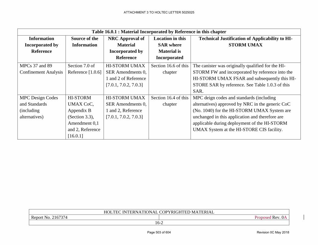
HOLTEC INTERNATIONAL COPYRIGHTED MATERIAL
Report No. 2167374 Proposed Rev. 0A
16-2
Table 16.0.1 : Material Incorporated by Reference in this chapter
Information
Incorporated by
Reference
Source of the
Information
NRC Approval of
Material
Incorporated by
Reference
Location in this
SAR where
Material is
Incorporated
Technical Justification of Applicability to HI-
STORM UMAX
MPCs 37 and 89
Confinement Analysis
Section 7.0 of
Reference [1.0.6]
HI-STORM UMAX
SER Amendments 0,
1 and 2 of Reference
[7.0.1, 7.0.2, 7.0.3]
Section 16.6 of this
chapter
The canister was originally qualified for the HI-
STORM FW and incorporated by reference into the
HI-STORM UMAX FSAR and subsequently this HI-
STORE SAR by reference. See Table 1.0.3 of this
SAR.
MPC Design Codes
and Standards
(including
alternatives)
HI-STORM
UMAX CoC,
Appendix B
(Section 3.3),
Amendment 0,1
and 2, Reference
[16.0.1]
HI-STORM UMAX
SER Amendments 0,
1 and 2, Reference
[7.0.1, 7.0.2, 7.0.3]
Section 16.4 of this
chapter
MPC deign codes and standards (including
alternatives) approved by NRC in the generic CoC
(No. 1040) for the HI-STORM UMAX System are
unchanged in this application and therefore are
applicable during deployment of the HI-STORM
UMAX System at the HI-STORE CIS facility.
ATTACHMENT 3 TO HOLTEC LETTER 5025025
Page 503 of 604 Revision 0C May 2018
HOLTEC INTERNATIONAL COPYRIGHTED MATERIAL
Report No. 2167374 Proposed Rev. 0A
16-3
16.1 FUNCTIONAL/OPERATING LIMITS, MONITORING
INSTRUMENTS, AND LIMITING CONTROL SETTINGS
This section provides a discussion of the operating controls and limits, monitoring instruments,
and limiting control settings for the HI-STORM UMAX system to assure long-term performance
consistent with the conditions analyzed in this SAR.
Functional and operating limits, monitoring instruments, and limiting control settings include
limits placed on fuel, waste handling, and storage conditions to protect the integrity of the fuel and
MPC, to maintain radiation workers exposure to radiation at the storage facility ALARA, and to
guard against the uncontrolled release of radioactive materials.
As discussed in Section 16.0, loading and unloading of MPC contents occurs at a 10CFR72 license
facility or a Part 50 license facility, in accordance with QA’d program procedures, prior to
shipment to the HI-STORE CIS Facility. Therefore fuel loadings are verified and records
maintained. Waste handling (fuel loading and MPC handling) at the site of origin is performed by
individuals appropriately trained and qualified. Upon arrival at the HI-STORE CIS Facility, MPC
handling shall be performed by personnel trained under the HI-STORE CIS Facility QA program.
The controls and limits apply to operating parameters and conditions which are observable,
detectable, and/or measurable. The HI-STORM UMAX system is completely passive during
storage and requires no monitoring instruments. A temperature monitoring system or visual
inspection of the vent screens to verify operability of the VVM heat removal system may be
employed in accordance with Technical Specification Limiting Condition for Operation (LCO)
3.1.1 (Appendix 16.A) .
ATTACHMENT 3 TO HOLTEC LETTER 5025025
Page 504 of 604 Revision 0C May 2018
HOLTEC INTERNATIONAL COPYRIGHTED MATERIAL
Report No. 2167374 Proposed Rev. 0A
16-4
16.2 LIMITING CONDITIONS
Limiting Conditions for Operation (LCO) specify the minimum capability or level of performance
that is required to assure that the HI-STORM UMAX system at the HI-STORE CIS can fulfill its
safety functions. Limiting Conditions are supported by analyses in this SAR (Chapters 5 – 9) and
provided in Appendix A of the proposed license (No. SNM-1051 Rev. 0 ), and their bases are
contained herein Appendix 16.A to this chapter.
ATTACHMENT 3 TO HOLTEC LETTER 5025025
Page 505 of 604 Revision 0C May 2018
HOLTEC INTERNATIONAL COPYRIGHTED MATERIAL
Report No. 2167374 Proposed Rev. 0A
16-5
16.3 SURVEILLANCE REQUIREMENTS
The analyses in this SAR show that the HI-STORE CIS Facility fulfills its safety functions,
provided that the Technical Specifications in Appendix A of the proposed license (No. SNM-1051
Rev. 0) are met. Surveillance requirements during storage operations at the HI-STORE CIS
Facility are provided in the Technical Specifications. Surveillance is required to ensure LCOs are
not violated.
ATTACHMENT 3 TO HOLTEC LETTER 5025025
Page 506 of 604 Revision 0C May 2018
HOLTEC INTERNATIONAL COPYRIGHTED MATERIAL
Report No. 2167374 Proposed Rev. 0A
16-6
16.4 DESIGN FEATURES
This subsection describes design features at the HI-STORE CIS Facility that are Important to
Safety. These features require design controls and fabrication controls. The design features,
detailed in this SAR and in Section 4.0 of Appendix A to the Proposed HI-STORE CIS Facility
license (No. SNM-1051), are established in specifications and drawings which are controlled
through the quality assurance program. Fabrication controls and inspections are in place to ensure
that the HI-STORE CIS Facility and important to safety systems are fabricated or constructed in
accordance with the licensing drawings in Section 1.5.
The HI-STORE and HI-STORM UMAX system and its components, as appropriate, have been
analyzed for specified normal, off-normal, and accident conditions, including extreme
environmental conditions. Analysis has shown that no credible condition or event prevents the
important to safety systems at from performing their function. As a result, there is no threat to
public health and safety from any postulated accident condition or analyzed event. When all
equipment are tested and placed into service in accordance with procedures developed for the
ISFSI, no failure of the system to perform its safety function is expected to occur.
Design codes and standards for the MPC, including alternatives, are incorporated by reference in
Section 3.3 of the NRC issued HI-STORM UMAX CoC No. 1040 Amendments 0, 1 and 2 .
Criticality control features of the MPC are referenced from Section 3.2 of the HI-STORM UMAX
CoC No. 1040 Amendments 0, 1 and 2. Design codes and standards, and criticality control features
are incorporated by reference into this chapter in accordance with Table 16.0.1.
The cask lifting equipment to be used at the HI-STORE CIS Facility, which includes specially
designed lifting devices, the Cask Transfer Building Crane, and the Vertical Cask Transporter,
have design features to render cask drops non-credible. These design features are described in
Section 4.5 of this SAR, and captured in Section 4.0 of Appendix A to the Proposed HI-STORE
CIS Facility Technical Specifications (No. SNM-1051).
Criteria and analyses (as applicable) for design features, including important to safety components
of drawings in Section 1.5 and ancillaries in Subsection 1.2.7, are provided in Chapters 4 – 9 of
this SAR.
ATTACHMENT 3 TO HOLTEC LETTER 5025025
Page 507 of 604 Revision 0C May 2018
HOLTEC INTERNATIONAL COPYRIGHTED MATERIAL
Report No. 2167374 Proposed Rev. 0A
16-7
16.5 ADMINISTRATIVE CONTROLS
Administrative control is established through the development of organizational and management
procedures, recordkeeping, review and audit systems, and reporting necessary to ensure that the
HI-STORE CIS Facility is managed in a safe and reliable manner. Administrative action, in
accordance with written procedures, shall be taken in the event of non-compliance.
Administrative controls for the HI-STORE CIS Facility in Appendix A to proposed HI-STORE
license No. SNM-1051 Rev. 0 is in alignment with Conduct of Operations in Chapter 10 of this
Safety Analysis Report.
ATTACHMENT 3 TO HOLTEC LETTER 5025025
Page 508 of 604 Revision 0C May 2018
HOLTEC INTERNATIONAL COPYRIGHTED MATERIAL
Report No. 2167374 Proposed Rev. 0A
16-8
16.6 REGULATORY COMPLIANCE
This chapter ensures regulatory compliance with 10CFR72.24, 72.26 and 72.44(a)(c) and (d).
10CFR72.24(g) requires identification and justification for the selection of those subjects that will
be probable license conditions and technical specifications
10CFR72.26 requires that each application under this part include proposed technical
specifications.
10CFR72.44(a) requires that each license includes license conditions
10CFR72.44(c) requires that each license includes technical specifications that must include
requirements in the following categories:
1. Functional and operating limits and monitoring instruments and limiting control settings.
2. Limiting conditions.
3. Surveillance requirements.
4. Design features
5. Administrative Controls
10CFR72.44(d) states that each license must include an annual report that specifies the quantity of
each of the principal radionuclides released to the environment.
This chapter discusses the technical specifications and LCO bases as applicable for the HI-STORE
CIS Facility or incorporated by reference. The Technical Specifications are license conditions.
Therefore, compliance with 10CFR72.44(c) is by extension compliance with 10CFR72.24(g) and
10CFR72.26. Technical specifications noted in 10CFR72.44(a) and (c) are discussed in this
chapter. 10CFR72.44(d) requirement for an annual report that specifies the quantity of each of the
principal radionuclides released to the environment is not discussed in the chapter and not required
for the HI-STORE CIS Facility. Analysis (Table 16.0.1) of the MPCs confirms it remains intact
and welds are not breached under normal, off-normal and accident conditions. Since the MPC
meets the ANSI N14.5 leaktight criteria (Subsection 10.3.3), release of effluents from MPCs are
on an order of magnitude to be considered negligible and with no impact on public health and
safety.
ATTACHMENT 3 TO HOLTEC LETTER 5025025
Page 509 of 604 Revision 0C May 2018
HOLTEC INTERNATIONAL COPYRIGHTED MATERIAL
Report No. 2167374 Proposed Rev. 0A
16.A-1
HI-STORE CIS Facility SAR
APPENDIX 16.A
TECHNICAL SPECIFICATION (LCOs) BASES
FOR THE HOLTEC HI-STORE CIS Facility
ATTACHMENT 3 TO HOLTEC LETTER 5025025
Page 510 of 604 Revision 0C May 2018
LCO Applicability
B 3.0
HOLTEC INTERNATIONAL COPYRIGHTED MATERIAL
Report No. 2167374 Proposed Rev. 0A
16.A-0
BASES TABLE OF CONTENTS
B 3.0 LIMITING CONDITION FOR OPERATION (LCO) APPLICABILITY ............ 16.A-3
B 3.0 SURVEILLANCE REQUIREMENT (SR) APPLICABILITY ............................. 16.A-6
B 3.1 SFSC INTEGRITY ............................................................................................... 16.A-11
B 3.1.2 SFSC Heat Removal System ................................................................................ 16.A-11
ATTACHMENT 3 TO HOLTEC LETTER 5025025
Page 511 of 604 Revision 0C May 2018
LCO Applicability
B 3.0
HOLTEC INTERNATIONAL COPYRIGHTED MATERIAL
Report No. 2167374 Proposed Rev. 0A
16.A-1
B 3.0 LIMITING CONDITION FOR OPERATION (LCO) APPLICABILITY
BASES
LCOs LCO 3.0.1, 3.0.2, 3.0.4, and 3.0.5 establish the general requirements applicable
to all Specifications and apply at all times, unless otherwise stated.
LCO 3.0.1 LCO 3.0.1 establishes the Applicability statement within each individual
Specification as the requirement for when the LCO is required to be met (i.e.,
when the facility is in the specified conditions of the Applicability statement of
each Specification).
LCO 3.0.2 LCO 3.0.2 establishes that upon discovery of a failure to meet an LCO, the
associated ACTIONS shall be met. The Completion Time of each Required
Action for an ACTIONS Condition is applicable from the point in time that an
ACTIONS Condition is entered. The Required Actions establish those remedial
measures that must be taken within specified Completion Times when the
requirements of an LCO are not met. This Specification establishes that:
a. Completion of the Required Actions within the specified Completion
Times constitutes compliance with a Specification; and
b. Completion of the Required Actions is not required when an LCO is met
within the specified Completion Time, unless otherwise specified.
There are two basic types of Required Actions. The first type of Required
Action specifies a time limit in which the LCO must be met. This time limit is
the Completion Time to restore a system or component or to restore variables to
within specified limits. Whether stated as a Required Action or not, correction
of the entered Condition is an action that may always be considered upon
entering ACTIONS. The second type of Required Action specifies the remedial
measures that permit continued operation that is not further restricted by the
Completion Time. In this case, compliance with the Required Actions provides
an acceptable level of safety for continued operation.
(continued)
ATTACHMENT 3 TO HOLTEC LETTER 5025025
Page 512 of 604 Revision 0C May 2018
LCO Applicability
B 3.0
HOLTEC INTERNATIONAL COPYRIGHTED MATERIAL
Report No. 2167374 Proposed Rev. 0A
16.A-2
BASES
LCO 3.0.2
(continued)
Completing the Required Actions is not required when an LCO is met or is no
longer applicable, unless otherwise stated in the individual Specifications.
The Completion Times of the Required Actions are also applicable when a
system or component is removed from service intentionally. The reasons for
intentionally relying on the ACTIONS include, but are not limited to,
performance of Surveillances, preventive maintenance, corrective maintenance,
or investigation of operational problems. Entering ACTIONS for these reasons
must be done in a manner that does not compromise safety. Intentional entry
into ACTIONS should not be made for operational convenience.
LCO 3.0.3 This specification is not applicable to a dry storage cask system because it
describes conditions under which a power reactor must be shut down when an
LCO is not met and an associated ACTION is not met or provided. The
placeholder is retained for consistency with the power reactor technical
specifications.
LCO 3.0.4 LCO 3.0.4 establishes limitations on changes in specified conditions in the
Applicability when an LCO is not met. It precludes placing the HI-STORM
UMAX System in a specified condition stated in that Applicability (e.g.,
Applicability desired to be entered) when the following exist:
a. Facility conditions are such that the requirements of the LCO would not
be met in the Applicability desired to be entered; and
b. Continued noncompliance with the LCO requirements, if the
Applicability were entered, would result in being required to exit the
Applicability desired to be entered to comply with the Required Actions.
Compliance with Required Actions that permit continuing with dry fuel storage
activities for an unlimited period of time in a specified condition provides an
acceptable level of safety for continued operation. This is without regard to the
status of the dry storage system. Therefore, in such cases, entry into a specified
condition in the Applicability may be made in accordance with the provisions
of the Required Actions. The provisions of this Specification should not be
interpreted as endorsing the failure to exercise the good practice of restoring
systems or components before entering an associated specified condition in the
Applicability.
(continued)
ATTACHMENT 3 TO HOLTEC LETTER 5025025
Page 513 of 604 Revision 0C May 2018
LCO Applicability
B 3.0
HOLTEC INTERNATIONAL COPYRIGHTED MATERIAL
Report No. 2167374 Proposed Rev. 0A
16.A-3
BASES
LCO 3.0.4
(continued)
The provisions of LCO 3.0.4 shall not prevent changes in specified conditions
in the Applicability that are required to comply with ACTIONS. In addition, the
provisions of LCO 3.0.4 shall not prevent changes in specified conditions in the
Applicability that are related to the unloading of an SFSC.
Exceptions to LCO 3.0.4 are stated in the individual Specifications. Exceptions
may apply to all the ACTIONS or to a specific Required Action of a
Specification.
LCO 3.0.5 LCO 3.0.5 establishes the allowance for restoring equipment to service under
administrative controls when it has been removed from service or determined to
not meet the LCO to comply with the ACTIONS. The sole purpose of this
Specification is to provide an exception to LCO 3.0.2 (e.g., to not comply with
the applicable Required Action(s)) to allow the performance of testing to
demonstrate:
The equipment being returned to service meets the LCO; or
Other equipment meets the applicable LCOs.
The administrative controls ensure the time the equipment is returned to service
in conflict with the requirements of the ACTIONS is limited to the time
absolutely necessary to perform the allowed testing. This Specification does not
provide time to perform any other preventive or corrective maintenance.
ATTACHMENT 3 TO HOLTEC LETTER 5025025
Page 514 of 604 Revision 0C May 2018
SR Applicability
B 3.0
HOLTEC INTERNATIONAL COPYRIGHTED MATERIAL
Report No. 2167374 Proposed Rev. 0A
16.A-4
B 3.0 SURVEILLANCE REQUIREMENT (SR) APPLICABILITY
BASES
SRs SR 3.0.1 through SR 3.0.4 establish the general requirements applicable to all
Specifications and apply at all times, unless otherwise stated.
SR 3.0.1 SR 3.0.1 establishes the requirement that SRs must be met during the specified
conditions in the Applicability for which the requirements of the LCO apply,
unless otherwise specified in the individual SRs. This Specification is to ensure
that Surveillances are performed to verify that systems and components meet
the LCO and variables are within specified limits. Failure to meet a Surveillance
within the specified Frequency, in accordance with SR 3.0.2, constitutes a
failure to meet an LCO.
Systems and components are assumed to meet the LCO when the associated SRs
have been met. Nothing in this Specification, however, is to be construed as
implying that systems or components meet the associated LCO when:
a. The systems or components are known to not meet the LCO, although
still meeting the SRs; or
b. The requirements of the Surveillance(s) are known to be not met
between required Surveillance performances.
Surveillances do not have to be performed when the HI-STORM UMAX
System is in a specified condition for which the requirements of the associated
LCO are not applicable, unless otherwise specified.
Surveillances, including Surveillances invoked by Required Actions, do not
have to be performed on equipment that has been determined to not meet the
LCO because the ACTIONS define the remedial measures that apply.
Surveillances have to be met and performed in accordance with SR 3.0.2, prior
to returning equipment to service. Upon completion of maintenance,
appropriate post-maintenance testing is required. This includes ensuring
applicable Surveillances are not failed and their most recent performance is in
accordance with SR 3.0.2. Post maintenance testing may not be possible in the
current specified conditions in the Applicability due to the necessary dry storage
cask system parameters not having been established. In these situations, the
equipment may be considered to meet the LCO provided testing has been
satisfactorily completed to the extent possible and the equipment is not
otherwise believed to be incapable of performing its function. This will allow
dry fuel storage activities to proceed to a specified condition where other
necessary post maintenance tests can be completed.
(continued)
ATTACHMENT 3 TO HOLTEC LETTER 5025025
Page 515 of 604 Revision 0C May 2018
SR Applicability
B 3.0
HOLTEC INTERNATIONAL COPYRIGHTED MATERIAL
Report No. 2167374 Proposed Rev. 0A
16.A-5
BASES
SR 3.0.2 SR 3.0.2 establishes the requirements for meeting the specified Frequency for
Surveillances and any Required Action with a Completion Time that requires
the periodic performance of the Required Action on a "once per..." interval.
SR 3.0.2 permits a 25% extension of the interval specified in the Frequency.
This extension facilitates Surveillance scheduling and considers facility
conditions that may not be suitable for conducting the Surveillance (e.g.,
transient conditions or other ongoing Surveillance or maintenance activities).
The 25% extension does not significantly degrade the reliability that results
from performing the Surveillance at its specified Frequency. This is based on
the recognition that the most probable result of any particular Surveillance being
performed is the verification of conformance with the SRs. The exceptions to
SR 3.0.2 are those Surveillances for which the 25% extension of the interval
specified in the Frequency does not apply. These exceptions are stated in the
individual Specifications as a Note in the Frequency stating, "SR 3.0.2 is not
applicable."
As stated in SR 3.0.2, the 25% extension also does not apply to the initial portion
of a periodic Completion Time that requires performance on a "once per..."
basis. The 25% extension applies to each performance after the initial
performance. The initial performance of the Required Action, whether it is a
particular Surveillance or some other remedial action, is considered a single
action with a single Completion Time. One reason for not allowing the 25%
extension to this Completion Time is that such an action usually verifies that no
loss of function has occurred by checking the status of redundant or diverse
components or accomplishes the function of the affected equipment in an
alternative manner.
The provisions of SR 3.0.2 are not intended to be used repeatedly merely as an
operational convenience to extend Surveillance intervals or periodic
Completion Time intervals beyond those specified.
(continued)
ATTACHMENT 3 TO HOLTEC LETTER 5025025
Page 516 of 604 Revision 0C May 2018
SR Applicability
B 3.0
HOLTEC INTERNATIONAL COPYRIGHTED MATERIAL
Report No. 2167374 Proposed Rev. 0A
16.A-6
BASES
SR 3.0.3 SR 3.0.3 establishes the flexibility to defer declaring affected equipment as not
meeting the LCO or an affected variable outside the specified limits when a
Surveillance has not been completed within the specified Frequency. A delay
period of up to 24 hours or up to the limit of the specified Frequency, whichever
is less, applies from the point in time that it is discovered that the Surveillance
has not been performed in accordance with SR 3.0.2, and not at the time that the
specified Frequency was not met.
This delay period provides adequate time to complete Surveillances that have
been missed. This delay period permits the completion of a Surveillance before
complying with Required Actions or other remedial measures that might
preclude completion of the Surveillance.
The basis for this delay period includes consideration of HI-STORM UMAX
System conditions, adequate planning, availability of personnel, the time
required to perform the Surveillance, the safety significance of the delay in
completing the required Surveillance, and the recognition that the most probable
result of any particular Surveillance being performed is the verification of
conformance with the requirements. When a Surveillance with a Frequency
based not on time intervals, but upon specified facility conditions, is discovered
not to have been performed when specified, SR 3.0.3 allows the full delay period
of 24 hours to perform the Surveillance.
SR 3.0.3 also provides a time limit for completion of Surveillances that become
applicable as a consequence of changes in the specified conditions in the
Applicability imposed by the Required Actions.
Failure to comply with specified Frequencies for SRs is expected to be an
infrequent occurrence. Use of the delay period established by SR 3.0.3 is a
flexibility which is not intended to be used as an operational convenience to
extend Surveillance intervals.
(continued)
ATTACHMENT 3 TO HOLTEC LETTER 5025025
Page 517 of 604 Revision 0C May 2018
SR Applicability
B 3.0
HOLTEC INTERNATIONAL COPYRIGHTED MATERIAL
Report No. 2167374 Proposed Rev. 0A
16.A-7
BASES
SR 3.0.3
(continued)
If a Surveillance is not completed within the allowed delay period, then the
equipment is considered to not meet the LCO or the variable is considered
outside the specified limits and the Completion Times of the Required Actions
for the applicable LCO Conditions begin immediately upon expiration of the
delay period. If a Surveillance is failed within the delay period, then the
equipment does not meet the LCO, or the variable is outside the specified limits
and the Completion Times of the Required Actions for the applicable LCO
Conditions begin immediately upon the failure of the Surveillance.
Completion of the Surveillance within the delay period allowed by this
Specification, or within the Completion Time of the ACTIONS, restores
compliance with SR 3.0.1.
SR 3.0.4 SR 3.0.4 establishes the requirement that all applicable SRs must be met before
entry into a specified condition in the Applicability.
This Specification ensures that system and component requirements and
variable limits are met before entry into specified conditions in the Applicability
for which these systems and components ensure safe conduct of dry fuel storage
activities.
The provisions of this Specification should not be interpreted as endorsing the
failure to exercise the good practice of restoring systems or components before
entering an associated specified condition in the Applicability.
However, in certain circumstances, failing to meet an SR will not result in SR
3.0.4 restricting a change in specified condition. When a system, subsystem,
division, component, device, or variable is outside its specified limits, the
associated SR(s) are not required to be performed per SR 3.0.1, which states that
Surveillances do not have to be performed on equipment that has been
determined to not meet the LCO. When equipment does not meet the LCO, SR
3.0.4 does not apply to the associated SR(s) since the requirement for the SR(s)
to be performed is removed. Therefore, failing to perform the Surveillance(s)
within the specified Frequency does not result in an SR 3.0.4 restriction to
changing specified conditions of the Applicability. However, since the LCO is
not met in this instance, LCO 3.0.4 will govern any restrictions that may (or may
not) apply to specified condition changes.
(continued)
ATTACHMENT 3 TO HOLTEC LETTER 5025025
Page 518 of 604 Revision 0C May 2018
SR Applicability
B 3.0
HOLTEC INTERNATIONAL COPYRIGHTED MATERIAL
Report No. 2167374 Proposed Rev. 0A
16.A-8
BASES
SR 3.0.4
(continued)
The provisions of SR 3.0.4 shall not prevent changes in specified conditions in
the Applicability that are required to comply with ACTIONS. In addition, the
provisions of LCO 3.0.4 shall not prevent changes in specified conditions in the
Applicability that are related to the unloading of an SFSC.
The precise requirements for performance of SRs are specified such that
exceptions to SR 3.0.4 are not necessary. The specific time frames and
conditions necessary for meeting the SRs are specified in the Frequency, in the
Surveillance, or both. This allows performance of Surveillances when the
prerequisite condition(s) specified in a Surveillance procedure require entry into
the specified condition in the Applicability of the associated LCO prior to the
performance or completion of a Surveillance. A Surveillance that could not be
performed until after entering the LCO Applicability would have its Frequency
specified such that it is not "due" until the specific conditions needed are met.
Alternately, the Surveillance may be stated in the form of a Note as not required
(to be met or performed) until a particular event, condition, or time has been
reached. Further discussion of the specific formats of SRs' annotation is found
in Section 1.4, Frequency.
ATTACHMENT 3 TO HOLTEC LETTER 5025025
Page 519 of 604 Revision 0C May 2018
HOLTEC INTERNATIONAL COPYRIGHTED MATERIAL
Report No. 2167374 Proposed Rev. 0A
16.A-9
B 3.1 SFSC Integrity
B 3.1.1 SFSC Heat Removal System
BASES
BACKGROUND The SFSC Heat Removal System is a passive, air-cooled, convective
heat transfer system that ensures heat from the MPC canister is
transferred to the environs by the chimney effect. Air is drawn into the
inlet ducts and travels down the space between the Cavity Enclosure
Container (CEC) and the Divider Shell, through the cut-outs at the
bottom of the Divider Shell, up the space between the Divider Shell and
the MPC, and out through the outlet duct. The MPC transfers its heat
from its surface to the air via natural convection. The buoyancy created
by the heating of the air creates a chimney effect.
APPLICABLE
SAFETY
ANALYSIS
The thermal analyses of the SFSC take credit for the decay heat from the
spent fuel assemblies being ultimately transferred to the ambient
environment surrounding the VVM. Transfer of heat away from the fuel
assemblies ensures that the fuel cladding and other SFSC component
temperatures do not exceed applicable limits. Under normal storage
conditions, the inlet and outlet duct screens are unobstructed and full air
flow occurs.
Analyses have been performed for half and complete obstruction of the
inlet duct screens. Blockage of half of the inlet ducts reduces air flow
through the VVM and decreases heat transfer from the MPC. Under this
off-normal condition, no SFSC components exceed the short term
temperature limits.
The complete blockage of all inlet air ducts stops normal air cooling of
the MPC. The MPC will continue to radiate heat to the relatively cooler
subgrade. With the loss of normal air cooling, the SFSC component
temperatures will increase toward their respective short-term
temperature limits. None of the components reach their temperature
limits over the duration of the analyzed event.
(continued)
ATTACHMENT 3 TO HOLTEC LETTER 5025025
Page 520 of 604 Revision 0C May 2018
HOLTEC INTERNATIONAL COPYRIGHTED MATERIAL
Report No. 2167374 Proposed Rev. 0A
16.A-10
BASES
LCO The SFSC Heat Removal System must be verified to be operable to
preserve the assumptions of the thermal analyses. Operability is defined
as 50% or more of the inlet vent duct areas are unblocked and available
for flow. Operability of the heat removal system ensures that the decay
heat generated by the stored fuel assemblies is transferred to the environs
at a sufficient rate to maintain fuel cladding and other SFSC component
temperatures within design limits.
The intent of this LCO is to address those occurrences of air duct screen
blockage that can be reasonably anticipated to occur from time to time
at the ISFSI (i.e., Design Event I and II class events per ANSI/ANS-
57.9). These events are of the type where corrective actions can usually
be accomplished within one 8-hour operating shift to restore the heat
removal system to operable status (e.g., removal of loose debris).
This LCO is not intended to address low frequency, unexpected Design
Event III and IV class events (ANSI/ANS-57.9) such as design basis
accidents and extreme environmental phenomena that could potentially
block one or more of the air ducts for an extended period of time (i.e.,
longer than the total Completion Time of the LCO). This class of events
is addressed site-specifically as required by Section 4.2.4 of Appendix
A to the license (SNM-1051).
APPLICABILITY The LCO is applicable during STORAGE OPERATIONS. Once a
VVM containing an MPC loaded with spent fuel has been placed in
storage, the heat removal system must be operable to ensure adequate
dissipation of the decay heat from the fuel assemblies.
ACTIONS A note has been added to the ACTIONS which states that, for this LCO,
separate Condition entry is allowed for each SFSC. This is acceptable
since the Required Actions for each Condition provide appropriate
compensatory measures for each SFSC not meeting the LCO.
Subsequent SFSCs that don't meet the LCO are governed by subsequent
Condition entry and application of associated Required Actions.
(continued)
ATTACHMENT 3 TO HOLTEC LETTER 5025025
Page 521 of 604 Revision 0C May 2018
HOLTEC INTERNATIONAL COPYRIGHTED MATERIAL
Report No. 2167374 Proposed Rev. 0A
16.A-11
BASES
ACTIONS
(continued)
A.1
Although the heat removal system remains operable, the blockage
should be cleared expeditiously.
B.1
If the heat removal system has been determined to be inoperable, it must
be restored to operable status within eight hours. Eight hours is a
reasonable period of time to take action to remove the obstructions in
the air flow path.
C.1
If the heat removal system cannot be restored to operable status within
eight hours, the VVM and the fuel may experience elevated
temperatures. Therefore, dose rates are required to be measured to verify
the effectiveness of the radiation shielding provided by the concrete.
This Action must be performed immediately and repeated every twelve
hours thereafter to provide timely and continued evaluation of the
effectiveness of the concrete shielding. As necessary, the system user
shall provide additional radiation protection measures such as temporary
shielding. The Completion Time is reasonable considering the expected
slow rate of deterioration, if any, of the concrete under elevated
temperatures.
C.2.1
In addition to Required Action C.1, efforts must continue to restore
cooling to the SFSC. Efforts must continue to restore the heat removal
system to operable status by removing the air flow obstruction(s) unless
optional Required Action C.2.2 is being implemented.
This Required Action must be complete in 24 hours. The Completion
Time is consistent with the thermal analyses of this event, which show
that all component temperatures remain below their short-term
temperature limits up to 32 hours after event initiation.
(continued)
ATTACHMENT 3 TO HOLTEC LETTER 5025025
Page 522 of 604 Revision 0C May 2018
HOLTEC INTERNATIONAL COPYRIGHTED MATERIAL
Report No. 2167374 Proposed Rev. 0A
16.A-12
BASES
ACTIONS
(continued)
C.2.1 (continued)
The Completion Time reflects the 8 hours to complete Required Action
B.1 and the appropriate balance of time consistent with the applicable
analysis results. The event is assumed to begin at the time the SFSC heat
removal system is declared inoperable. This is reasonable considering
the low probability of all inlet ducts becoming simultaneously blocked.
C.2.2
In lieu of implementing Required Action C.2.1, transfer of the MPC into
a TRANSFER CASK will place the MPC in an analyzed condition and
ensure adequate fuel cooling until actions to correct the heat removal
system inoperability can be completed. Transfer of the MPC into a
TRANSFER CASK removes the SFSC from the LCO Applicability
since STORAGE OPERATIONS does not include times when the MPC
resides in the TRANSFER CASK.
An engineering evaluation must be performed to determine if any
deterioration which prevents the VVM from performing its design
function. If the evaluation is successful and the air inlet duct screens
have been cleared, the VVM heat removal system may be considered
operable and the MPC transferred back into the VVM. Compliance with
LCO 3.1.1 is then restored. If the evaluation is unsuccessful, the user
must transfer the MPC into a different, fully qualified VVM to resume
STORAGE OPERATIONS and restore compliance with LCO 3.1.1
In lieu of performing the engineering evaluation, the user may opt to
proceed directly to transferring the MPC into a different, fully qualified
VVM.
The Completion Time of 24 hours reflects the Completion Time from
Required Action C.2.1 to ensure component temperatures remain below
their short-term temperature limits for the respective decay heat loads.
(continued)
ATTACHMENT 3 TO HOLTEC LETTER 5025025
Page 523 of 604 Revision 0C May 2018
HOLTEC INTERNATIONAL COPYRIGHTED MATERIAL
Report No. 2167374 Proposed Rev. 0A
16.A-13
BASES
SURVEILLANCE
REQUIREMENTS
SR 3.1.2
The long-term integrity of the stored fuel is dependent on the ability of
the SFSC to reject heat from the MPC to the environment. There are
two options for implementing SR 3.1.1, either of which is acceptable for
demonstrating that the heat removal system is OPERABLE.
Visual observation that all air inlet duct screens are unobstructed ensures
that the SFSC is operable. If greater than 50% of the air inlet duct
screens are blocked the heat removal system is inoperable and this LCO
is not met. While 50% or less blockage of the total air inlet duct screen
area does not constitute inoperability of the heat removal system,
corrective actions should be taken promptly to remove the obstruction
and restore full flow.
Visual observation of air outlet duct screen blockage does not constitute
inoperability of the heat removal system; however, corrective action
should be taken to promptly remove the obstruction.
As an alternative, for VVMs with air temperature monitoring
instrumentation installed in the air outlets, the temperature difference
between the outlet air and the ambient air may be monitored to verify
operability of the heat removal system. Blocked air inlet duct screens
will reduce air flow and increase the outlet duct air temperature. Based
on the analyses, if the temperature difference between the ambient air
and the outlet duct air meets the criteria in the LCO, adequate air flow is
occurring to provide assurance of long term fuel cladding integrity. The
reference ambient temperature used to perform this Surveillance shall be
measured at the ISFSI facility.
The Frequency of 24 hours is reasonable based on the time necessary for
SFSC components to heat up to unacceptable temperatures assuming
design basis heat loads, and allowing for corrective actions to take place
upon discovery of blockage of air ducts.
REFERENCES 1. SAR Chapter 6
2. ANSI/ANS 57.9-1992
ATTACHMENT 3 TO HOLTEC LETTER 5025025
Page 524 of 604 Revision 0C May 2018
HOLTEC INTERNATIONAL COPYRIGHTED MATERIAL
Report No.: HI-2167374 Proposed Rev. 0A
17-1
CHAPTER 17: MATERIAL EVALUATION
17.0 INTRODUCTION
This chapter presents an assessment of the materials selected for use in the HI-STORM UMAX
system [1.0.6] components that are envisaged to be deployed at the HI-STORE CIS facility. The
assessment of the materials selected for use in the MPCs is provided in the previously licensed HI-
STORM FW system FSAR [1.3.7]. The fuel loading, dewatering, drying and welding of the
canister occur at the nuclear plant site, the material selection decisions for the canister are
comprehensively covered in [1.3.7]. The canisters will arrive at the HI-STORE site in ready-to-
store condition; no material selection decision vis-à-vis the canisters will be made at the HI-
STORE site. Because the environmental conditions and design criteria for the MPCs for use at HI-
STORE are completely bounded by those in the HI-STORM FW (and HI-STORM UMAX)
dockets, reference is made to the material selection considerations for the MPCs (canisters) in their
native docket (HI-STORM FW FSAR). The information on the suitability of the MPC for the local
environmental conditions at HI-STORE CIS, however, underpins the Aging Management program
presented in Chapter 18.
The HI-STORM UMAX components must withstand the environmental conditions experienced
during normal operation, off-normal conditions, and accident conditions for the entire service life
of the interim storage facility (please see Table 17.0.1).
Chapter 1 provides a general description of the HI-STORM UMAX System including information
on materials of construction. The ITS categories of the principal materials of construction in the
HI-STORM UMAX VVM and ISFSI system are identified in the drawing package provided in
Section 1.5.
Nevertheless, for completeness, it is necessary that the material considerations applicable to HI-
STORM UMAX be independently evaluated for compliance with the ISG-15 [17.0.1] which
contains the latest NRC position in this matter. The principal purpose of ISG-15 is to evaluate the
dry cask storage system to ensure adequate material performance of components deemed to be
important-to-safety at an independent spent fuel storage installation (ISFSI) under normal, off-
normal, and accident conditions.
ISG-15 sets down the following general acceptance criteria for material evaluation:
• The safety analysis report should describe all materials used for dry spent fuel storage
components important-to-safety, and should consider the suitability of those materials for
their intended functions in sufficient detail to evaluate their effectiveness in relation to all
safety functions.
• The dry spent fuel storage system should employ materials that are compatible with wet
and dry spent fuel loading and unloading operations and facilities. These materials should
not degrade to the extent that a safety concern is created.
All references are in placed within square brackets in this report and are compiled in Chapter 19 of this report.
ATTACHMENT 3 TO HOLTEC LETTER 5025025
Page 525 of 604 Revision 0C May 2018
HOLTEC INTERNATIONAL COPYRIGHTED MATERIAL
Report No.: HI-2167374 Proposed Rev. 0A
17-2
The information compiled in this chapter seeks to address the above acceptance criteria in full
measure for the HI-STORM UMAX VVM and ISFSI. To perform the material suitability
evaluation, it is necessary to characterize the following for each component: (i) the applicable
environment, (ii) potential degradation modes and (iii) potential hazards to continued effectiveness
of the selected material.
The material evaluation presented in this chapter is intended to be complete, even though a’ priori
conclusion of the adequacy of the materials can be made on the basis of the following facts:
i. The materials used in HI-STORM UMAX VVM are identical to those used in the widely
deployed HI-STORM 100 System (Docket No. 72-1014) [1.3.3] including its underground
VVM denoted as HI-STORM 100U and the HI-STORM FW system (Docket No. 72-1032)
[1.3.7].
ii. As can be ascertained from Table 2.7.1, the thermal environment in the HI-STORM
UMAX system at the HI-STORE site is bounded by the design basis for its generic
certification in the HI-STORM UMAX docket [1.0.6].
In this chapter, the significant mechanical, thermal, radiological, and metallurgical properties of
materials identified for use in the components of the HI-STORM UMAX System and ISFSI are
presented. The material evaluation effort is directed towards the interim storage at HI-STORE CIS
for its intended service life and its consequences to the system’s continued safety. Table 17.0.1
provides the expected licensing, design and service life data for the HI-STORE CIS facility.
Because the materials designated to be used at the HI-STORE CIS facility have a long pedigree of
usage in other HI-STORM dockets, their mechanical and thermos-physical properties are well
documented in the prior FSARs approved by the NRC. The identification of such
sections/appendices/tables that are adopted by reference herein is summarized in Table 17.0.2.
ATTACHMENT 3 TO HOLTEC LETTER 5025025
Page 526 of 604 Revision 0C May 2018
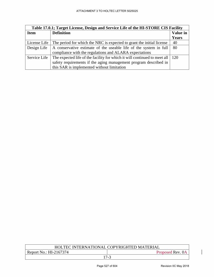
HOLTEC INTERNATIONAL COPYRIGHTED MATERIAL
Report No.: HI-2167374 Proposed Rev. 0A
17-3
Table 17.0.1; Target License, Design and Service Life of the HI-STORE CIS Facility
Item Definition Value in
Years
License Life The period for which the NRC is expected to grant the initial license 40
Design Life A conservative estimate of the useable life of the system in full
compliance with the regulations and ALARA expectations
80
Service Life The expected life of the facility for which it will continued to meet all
safety requirements if the aging management program described in
this SAR is implemented without limitation
120
ATTACHMENT 3 TO HOLTEC LETTER 5025025
Page 527 of 604 Revision 0C May 2018
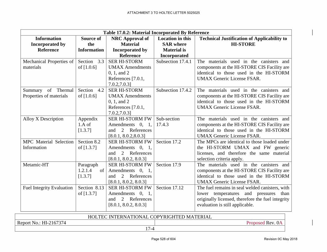
HOLTEC INTERNATIONAL COPYRIGHTED MATERIAL
Report No.: HI-2167374 Proposed Rev. 0A
17-4
Table 17.0.2: Material Incorporated By Reference
Information
Incorporated by
Reference
Source of
the
Information
NRC Approval of
Material
Incorporated by
Reference
Location in this
SAR where
Material is
Incorporated
Technical Justification of Applicability to
HI-STORE
Mechanical Properties of
materials
Section 3.3
of [1.0.6]
SER HI-STORM
UMAX Amendments
0, 1, and 2
References [7.0.1,
7.0.2,7.0.3]
Subsection 17.4.1 The materials used in the canisters and
components at the HI-STORE CIS Facility are
identical to those used in the HI-STORM
UMAX Generic License FSAR.
Summary of Thermal
Properties of materials
Section 4.2
of [1.0.6]
SER HI-STORM
UMAX Amendments
0, 1, and 2
References [7.0.1,
7.0.2,7.0.3]
Subsection 17.4.2 The materials used in the canisters and
components at the HI-STORE CIS Facility are
identical to those used in the HI-STORM
UMAX Generic License FSAR.
Alloy X Description Appendix
1.A of
[1.3.7]
SER HI-STORM FW
Amendments 0, 1,
and 2 References
[8.0.1, 8.0.2,8.0.3]
Sub-section
17.4.3
The materials used in the canisters and
components at the HI-STORE CIS Facility are
identical to those used in the HI-STORM
UMAX Generic License FSAR.
MPC Material Selection
Information
Section 8.2
of [1.3.7]
SER HI-STORM FW
Amendments 0, 1,
and 2 References
[8.0.1, 8.0.2, 8.0.3]
Section 17.2 The MPCs are identical to those loaded under
the HI-STORM UMAX and FW generic
licenses, and therefore the same material
selection criteria apply.
Metamic-HT Paragraph
1.2.1.4 of
[1.3.7]
SER HI-STORM FW
Amendments 0, 1,
and 2 References
[8.0.1, 8.0.2, 8.0.3]
Section 17.9 The materials used in the canisters and
components at the HI-STORE CIS Facility are
identical to those used in the HI-STORM
UMAX Generic License FSAR.
Fuel Integrity Evaluation Section 8.13
of [1.3.7]
SER HI-STORM FW
Amendments 0, 1,
and 2 References
[8.0.1, 8.0.2, 8.0.3]
Section 17.12 The fuel remains in seal welded canisters, with
lower temperatures and pressures than
originally licensed, therefore the fuel integrity
evaluation is still applicable.
ATTACHMENT 3 TO HOLTEC LETTER 5025025
Page 528 of 604 Revision 0C May 2018
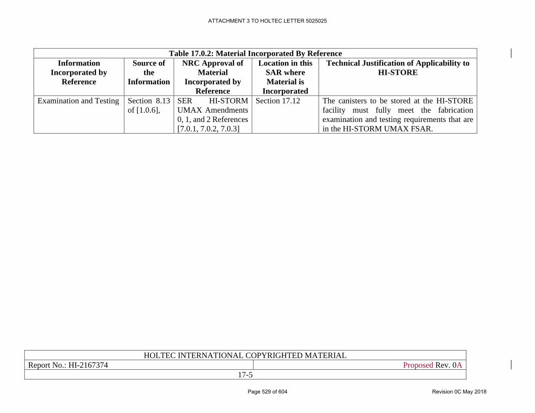
HOLTEC INTERNATIONAL COPYRIGHTED MATERIAL
Report No.: HI-2167374 Proposed Rev. 0A
17-5
Table 17.0.2: Material Incorporated By Reference
Information
Incorporated by
Reference
Source of
the
Information
NRC Approval of
Material
Incorporated by
Reference
Location in this
SAR where
Material is
Incorporated
Technical Justification of Applicability to
HI-STORE
Examination and Testing Section 8.13
of [1.0.6],
SER HI-STORM
UMAX Amendments
0, 1, and 2 References
[7.0.1, 7.0.2, 7.0.3]
Section 17.12 The canisters to be stored at the HI-STORE
facility must fully meet the fabrication
examination and testing requirements that are
in the HI-STORM UMAX FSAR.
ATTACHMENT 3 TO HOLTEC LETTER 5025025
Page 529 of 604 Revision 0C May 2018
HOLTEC INTERNATIONAL COPYRIGHTED MATERIAL
Report No.: HI-2167374 Proposed Rev. 0A
17-6
17.1 MATERIAL DEGRADATION MODES
Tables 17.1.1, 17.1.2 and 17.1.3 provide a summary of the environmental states, potential
degradation modes, and hazards applicable to the HI-STORM UMAX modules and other ITS
SSCs that are specific to HI-STORE CIS facility. The facility specific SSCs employ similar
materials as to those employed in HI-STORM UMAX modules. These components include HI-
TRAC CS, CTB Crane, Lift Yokes (Transfer Cask and Transport Cask), MPC Lift Attachments,
Special Lifting devices, Transport Cask Lift Beams and Tilt Frames. Table 17.1.4 provides the
listing of material types that are important to safety and are subject to the ambient environmental
of the HI-STORE Facility.
To provide a proper context for the subsequent evaluations, the potential degradation mechanisms
applicable to the ventilated systems are summarized in Table 17.1.5. The degradation mechanisms
listed in Table 17.1.5 are considered in the suitability evaluation presented in this chapter.
ATTACHMENT 3 TO HOLTEC LETTER 5025025
Page 530 of 604 Revision 0C May 2018
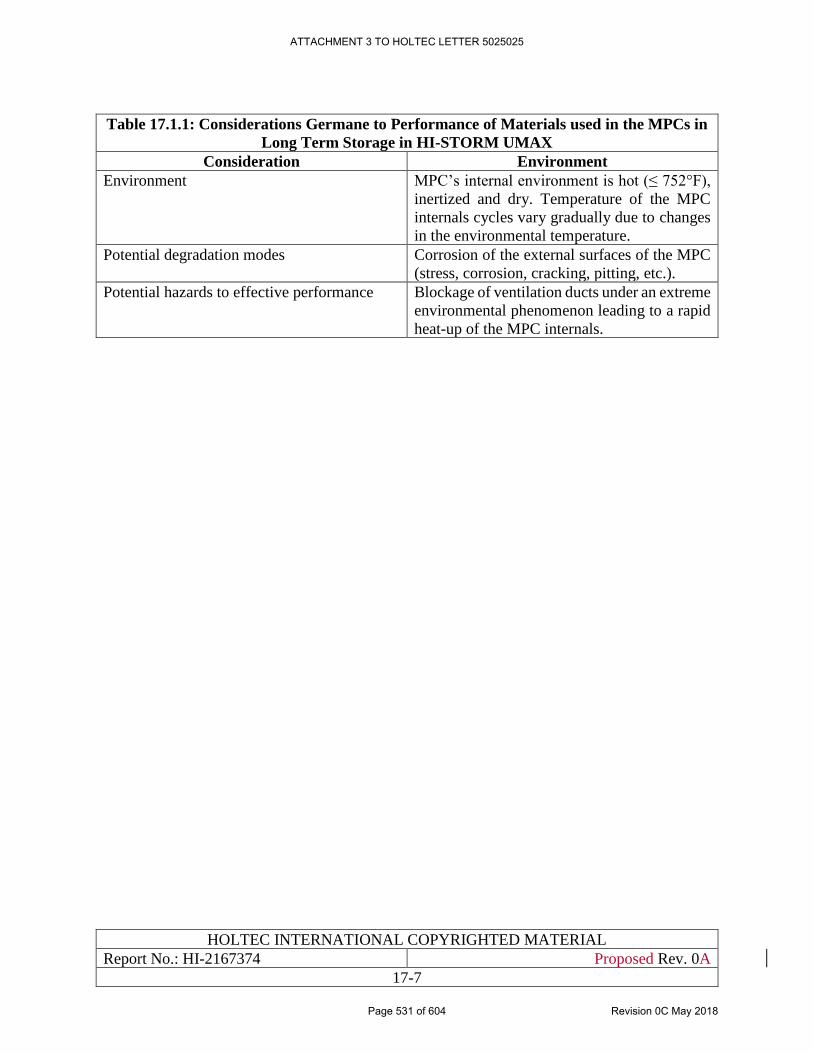
HOLTEC INTERNATIONAL COPYRIGHTED MATERIAL
Report No.: HI-2167374 Proposed Rev. 0A
17-7
Table 17.1.1: Considerations Germane to Performance of Materials used in the MPCs in
Long Term Storage in HI-STORM UMAX
Consideration Environment
Environment MPC’s internal environment is hot (≤ 752°F),
inertized and dry. Temperature of the MPC
internals cycles vary gradually due to changes
in the environmental temperature.
Potential degradation modes Corrosion of the external surfaces of the MPC
(stress, corrosion, cracking, pitting, etc.).
Potential hazards to effective performance Blockage of ventilation ducts under an extreme
environmental phenomenon leading to a rapid
heat-up of the MPC internals.
ATTACHMENT 3 TO HOLTEC LETTER 5025025
Page 531 of 604 Revision 0C May 2018
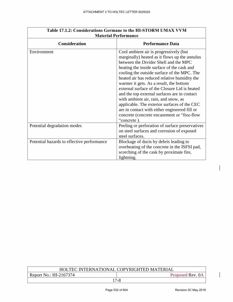
HOLTEC INTERNATIONAL COPYRIGHTED MATERIAL
Report No.: HI-2167374 Proposed Rev. 0A
17-8
Table 17.1.2: Considerations Germane to the HI-STORM UMAX VVM
Material Performance
Consideration Performance Data
Environment Cool ambient air is progressively (but
marginally) heated as it flows up the annulus
between the Divider Shell and the MPC
heating the inside surface of the cask and
cooling the outside surface of the MPC. The
heated air has reduced relative humidity the
warmer it gets. As a result, the bottom
external surface of the Closure Lid is heated
and the top external surfaces are in contact
with ambient air, rain, and snow, as
applicable. The exterior surfaces of the CEC
are in contact with either engineered fill or
concrete (concrete encasement or “free-flow
“concrete ).
Potential degradation modes Peeling or perforation of surface preservatives
on steel surfaces and corrosion of exposed
steel surfaces.
Potential hazards to effective performance Blockage of ducts by debris leading to
overheating of the concrete in the ISFSI pad,
scorching of the cask by proximate fire,
lightning.
ATTACHMENT 3 TO HOLTEC LETTER 5025025
Page 532 of 604 Revision 0C May 2018
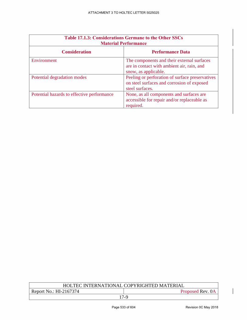
HOLTEC INTERNATIONAL COPYRIGHTED MATERIAL
Report No.: HI-2167374 Proposed Rev. 0A
17-9
Table 17.1.3: Considerations Germane to the Other SSCs
Material Performance
Consideration Performance Data
Environment The components and their external surfaces
are in contact with ambient air, rain, and
snow, as applicable.
Potential degradation modes Peeling or perforation of surface preservatives
on steel surfaces and corrosion of exposed
steel surfaces.
Potential hazards to effective performance None, as all components and surfaces are
accessible for repair and/or replaceable as
required.
ATTACHMENT 3 TO HOLTEC LETTER 5025025
Page 533 of 604 Revision 0C May 2018
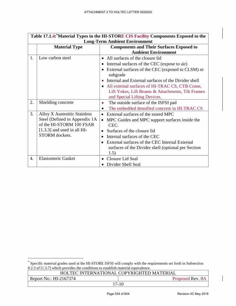
HOLTEC INTERNATIONAL COPYRIGHTED MATERIAL
Report No.: HI-2167374 Proposed Rev. 0A
17-10
Table 17.1.4:*Material Types in the HI-STORE CIS Facility Components Exposed to the
Long-Term Ambient Environment
Material Type Components and Their Surfaces Exposed to
Ambient Environment
1. Low carbon steel • All surfaces of the closure lid
• Internal surfaces of the CEC (expose to air)
• External surfaces of the CEC (exposed to CLSM) or
subgrade
• Internal and External surfaces of the Divider shell
• All external surfaces of HI-TRAC CS, CTB Crane,
Lift Yokes, Lift Beams & Attachments, Tilt Frames
and Special Lifting Devices.
2. Shielding concrete • The outside surface of the ISFSI pad
• The embedded densified concrete in HI-TRAC CS
3. Alloy X Austenitic Stainless
Steel (Defined in Appendix 1A
of the HI-STORM 100 FSAR
[1.3.3] and used in all HI-
STORM dockets.
• External surfaces of the stored MPC
• MPC Guides and MPC support surfaces inside the
CEC.
• Surfaces of the closure lid
• Internal surfaces of the CEC
• External surfaces of the CEC Internal External
surfaces of the Divider shell (optional per Section
1.5)
4. Elastomeric Gasket • Closure Lid Seal
• Divider Shell Seal
* Specific material grades used at the HI-STORE ISFSI will comply with the requirements set forth in Subsection
8.2.3 of [1.3.7] which provides the conditions to establish material equivalence.
ATTACHMENT 3 TO HOLTEC LETTER 5025025
Page 534 of 604 Revision 0C May 2018
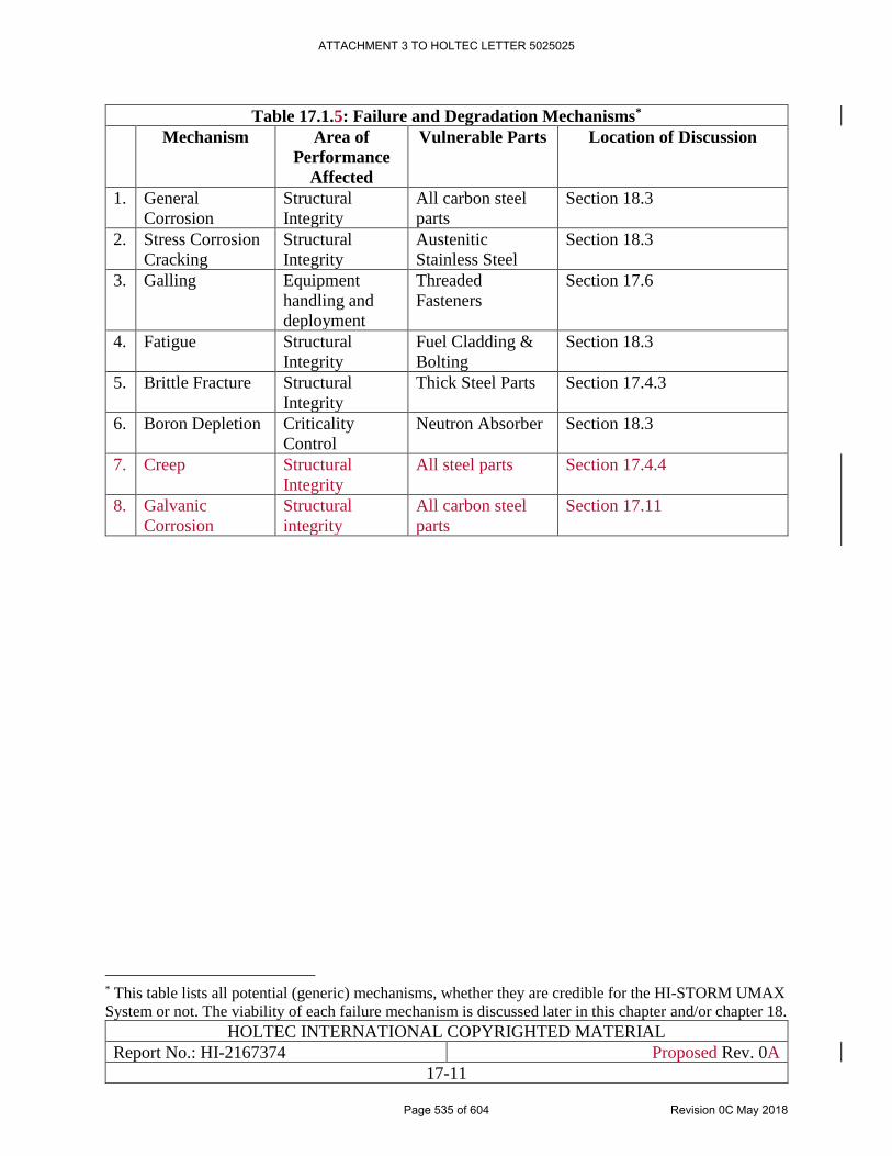
HOLTEC INTERNATIONAL COPYRIGHTED MATERIAL
Report No.: HI-2167374 Proposed Rev. 0A
17-11
Table 17.1.5: Failure and Degradation Mechanisms*
Mechanism Area of
Performance
Affected
Vulnerable Parts Location of Discussion
1. General
Corrosion
Structural
Integrity
All carbon steel
parts
Section 18.3
2. Stress Corrosion
Cracking
Structural
Integrity
Austenitic
Stainless Steel
Section 18.3
3. Galling Equipment
handling and
deployment
Threaded
Fasteners
Section 17.6
4. Fatigue Structural
Integrity
Fuel Cladding &
Bolting
Section 18.3
5. Brittle Fracture Structural
Integrity
Thick Steel Parts Section 17.4.3
6. Boron Depletion Criticality
Control
Neutron Absorber Section 18.3
7. Creep Structural
Integrity
All steel parts Section 17.4.4
8. Galvanic
Corrosion
Structural
integrity
All carbon steel
parts
Section 17.11
* This table lists all potential (generic) mechanisms, whether they are credible for the HI-STORM UMAX
System or not. The viability of each failure mechanism is discussed later in this chapter and/or chapter 18.
ATTACHMENT 3 TO HOLTEC LETTER 5025025
Page 535 of 604 Revision 0C May 2018
HOLTEC INTERNATIONAL COPYRIGHTED MATERIAL
Report No.: HI-2167374 Proposed Rev. 0A
17-12
17.2 MATERIAL SELECTION
The acceptance criteria for the materials subject to long-term storage conditions in HI-STORM
UMAX are extracted from ISG-15 [17.0.1] as follows:
a. The material properties of a dry spent fuel storage component should meet its service
requirements in the proposed cask system for the duration of the licensing period.
b. The materials that comprise the dry spent fuel storage should maintain their physical and
mechanical properties during all conditions of operations. The spent fuel should be readily
retrievable without posing operational safety problems.
c. Over the range of temperatures expected prior to and during the storage period, any ductile-
to-brittle transition of the dry spent fuel storage materials, used for structural and
nonstructural components, should be evaluated for its effects on safety.
d. Dry spent fuel storage gamma shielding materials should not experience slumping or loss
of shielding effectiveness to an extent that compromises safety. The shield should perform
its intended function throughout the licensed service period.
e. Dry spent fuel storage materials used for neutron absorption should be designed to perform
their safety function.
f. Dry spent fuel storage protective coatings should remain intact and adherent during all
loading and unloading operations within wet or dry spent fuel facilities, and during long-
term storage.
The qualification of the materials used in the MPC types is documented in Section 8.2 of the HI-
STORM FW FSAR [1.3.7] incorporated herein by reference. The material selection opportunities
for the HI-STORM UMAX system, therefore, are limited to the HI-TRAC CS and the VVM
module assembly components and the reinforced concrete structures that support or surround them.
However, to obviate the need for any new material qualification effort, the materials permitted for
the HI-STORM UMAX system are limited to those certified in other HI-STORM 100 and HI-
STORM FW dockets. The material qualification information presented in this chapter is
accordingly adapted from Docket Number 72-1032 [1.3.7].
17.2.1 Structural Materials
17.2.1.1 Cask Components and Their Constituent Materials
The major structural material that is used in the HI-STORM UMAX VVM is steel. The concrete
in the VVM Closure Lid does not play a major structural role but is present in large quantity for
the main purpose of shielding. The major structural materials in the ISFSI structures are the
concrete and rebars in the Support Foundation Pad, the ISFSI Pad and the Self-hardening
Engineered Subgrade in the inter-CEC space.
17.2.1.2 Synopsis of Structural Materials
i. Carbon Steel, Low-Alloy Steel
ATTACHMENT 3 TO HOLTEC LETTER 5025025
Page 536 of 604 Revision 0C May 2018
HOLTEC INTERNATIONAL COPYRIGHTED MATERIAL
Report No.: HI-2167374 Proposed Rev. 0A
17-13
Materials for the HI-STORM UMAX VVM are selected to preclude brittle fracture. Details of
discussions are provided in Section 17.4 herein.
ii. Reinforced Concrete
All reinforced concrete load bearing structures (concrete and rebar) in the HI-STORM UMAX
ISFSI will conform to stress criteria of ACI-318(2005) [5.3.1]. Section 3.3 in the HI-STORM
UMAX FSAR [1.0.6] provides properties for reinforced concrete to be used for the HI-STORM
UMAX interfacing ISFSI structures. The service life of the ISFSI structures is specified to be the
same as that of the HI-STORM UMAX VVM.
iii. Self-hardening Engineered Subgrade
The SES material (i.e., lean concrete or CLSM) used in the HI-STORM UMAX ISFSI will
conform to the stress criteria of ACI-318(2005) or ACI-229(1999). Tables 2.3.2 and 3.3.4 in the
HI-STORM UMAX FSAR [1.0.6] provide the critical properties for the SES material used for HI-
STORM UMAX ISFSI safety analyses. In the interest of a reliably robust design and long service
life, additional performance properties of CLSM are listed in table below. The service life for the
SES is the same as that of the VVM and ISFSI reinforced concrete.
iv. Austenitic Stainless Steel
Austenitic stainless steel may be used for certain components of the HI-STORM UMAX VVM.
Chapter 5 provides the structural evaluation for the HI-STORM UMAX VVM using the governing
structural materials. Since stainless steel materials do not undergo a ductile-to-brittle transition in
the minimum permissible service temperature range of the HI-STORM UMAX System, brittle
fracture is not a concern for stainless steel components. It is recognized that austenitic stainless
steels are qualified for use with other HI-STORM UMAX System components (namely Alloy X
for the MPC) by the HI-STORM FW FSAR.
Chapter 5 discusses the structural evaluations of the HI-STORM UMAX System components and
ISFSI structures. It is demonstrated that the structural steel components of the HI-STORM UMAX
VVM and the SFP concrete meet the allowable stress limits for normal, off-normal, and accident
loading conditions as applicable. The analyses documented in Chapter 5 also demonstrate that the
SES remains stable under the Design Basis Earthquake condition and provides sufficient
protection to the stored MPC even if any side of the self- hardening sub-grade (SES) is fully
exposed during excavation for ISFSI expansion.
17.2.2 Non-Structural Materials
i. Plain Concrete
Plain concrete is specified for the VVM Closure Lid for its shielding properties and also as an
encasement around the exterior of the VVM CEC shell, if required, for its corrosion mitigation
properties. The requirements on the shielding concrete are specified in Table 4.3.3.
The shielding performance of the plain concrete is maintained by ensuring that the minimum
concrete density is met during construction and the allowable concrete temperature limits are not
exceeded. The durability and thermal analyses for normal and off-normal conditions are carried
out in this SAR to ensure that the plain concrete does not exceed the allowable long term
temperature limit provided in Chapter 4. The strength analysis is carried out in Chapter 5 of this
SAR.
ATTACHMENT 3 TO HOLTEC LETTER 5025025
Page 537 of 604 Revision 0C May 2018
HOLTEC INTERNATIONAL COPYRIGHTED MATERIAL
Report No.: HI-2167374 Proposed Rev. 0A
17-14
ii. Insulation
The Divider Shell is lined with insulation on its outer surface to prevent excessive heating of the
ISFSI pad. The insulation selected shall be suitable for high temperature and high humidity
operation and shall be foil faced, jacketed, or otherwise made water-resistant to ensure the required
thermal resistance is maintained in accordance with Chapter 6. The high zinc content present in
the coating of the Divider Shell provides protection for the jacketing or foil from the potential of
galvanic corrosion. To ensure adequate radiation resistance, the insulation blanket does not contain
any organic binders. The damage threshold for ceramics is known to be approximately 1x10¹⁰
Rads. Chloride corrosion is not a concern since chloride leachables are limited and sufficiently
low. Stress corrosion cracking of the foil or jacketing, whether made from stainless steel or other
material, is not an applicable corrosion mechanism due to minimal stresses derived from self-
weight. The foil or jacketing and attachment hardware shall either have sufficient corrosion
resistance (e.g., stainless steel, aluminum, or galvanized steel) or shall be protected with a suitable
surface preservative. The insulation is adequately secured to prevent blockage of the ventilation
passages in case of failure of a single attachment (strap, clamp, bolt or other attachment hardware).
Table 17.2.2 provides the acceptance criteria for the selection of insulation material for the VVM
assembly and ranks them in order of importance.
ATTACHMENT 3 TO HOLTEC LETTER 5025025
Page 538 of 604 Revision 0C May 2018
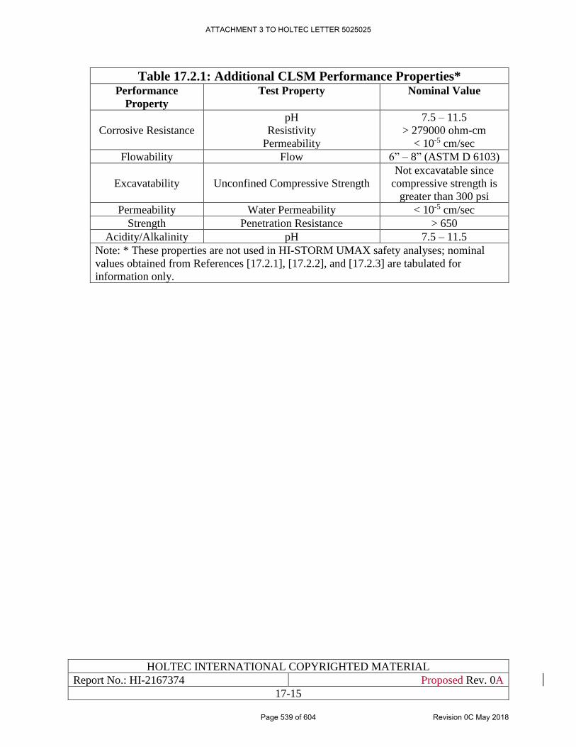
HOLTEC INTERNATIONAL COPYRIGHTED MATERIAL
Report No.: HI-2167374 Proposed Rev. 0A
17-15
Table 17.2.1: Additional CLSM Performance Properties*
Performance
Property
Test Property Nominal Value
Corrosive Resistance
pH
Resistivity
Permeability
7.5 – 11.5
> 279000 ohm-cm
< 10-5 cm/sec
Flowability Flow 6” – 8” (ASTM D 6103)
Excavatability Unconfined Compressive Strength
Not excavatable since
compressive strength is
greater than 300 psi
Permeability Water Permeability < 10-5 cm/sec
Strength Penetration Resistance > 650
Acidity/Alkalinity pH 7.5 – 11.5
Note: * These properties are not used in HI-STORM UMAX safety analyses; nominal
values obtained from References [17.2.1], [17.2.2], and [17.2.3] are tabulated for
information only.
ATTACHMENT 3 TO HOLTEC LETTER 5025025
Page 539 of 604 Revision 0C May 2018
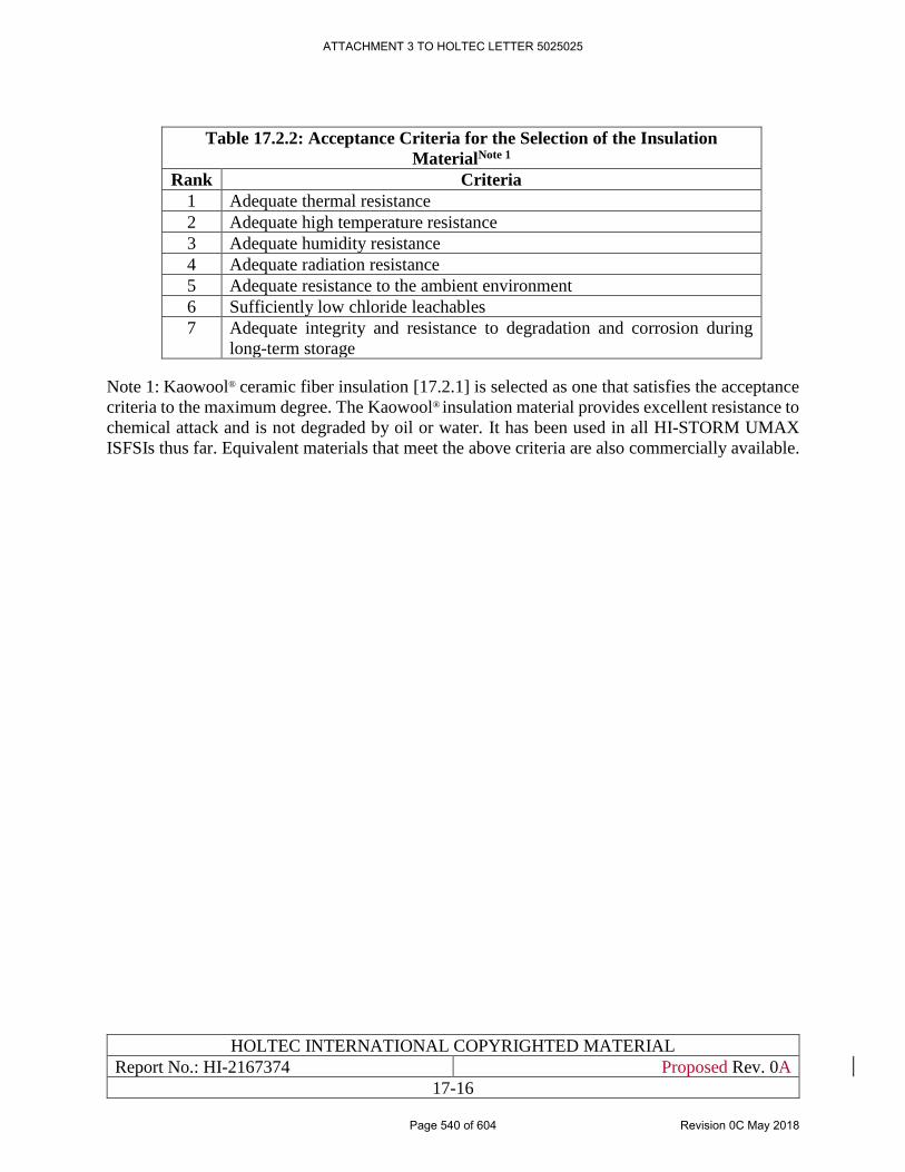
HOLTEC INTERNATIONAL COPYRIGHTED MATERIAL
Report No.: HI-2167374 Proposed Rev. 0A
17-16
Table 17.2.2: Acceptance Criteria for the Selection of the Insulation
MaterialNote 1
Rank Criteria
1 Adequate thermal resistance
2 Adequate high temperature resistance
3 Adequate humidity resistance
4 Adequate radiation resistance
5 Adequate resistance to the ambient environment
6 Sufficiently low chloride leachables
7 Adequate integrity and resistance to degradation and corrosion during
long-term storage
Note 1: Kaowool® ceramic fiber insulation [17.2.1] is selected as one that satisfies the acceptance
criteria to the maximum degree. The Kaowool® insulation material provides excellent resistance to
chemical attack and is not degraded by oil or water. It has been used in all HI-STORM UMAX
ISFSIs thus far. Equivalent materials that meet the above criteria are also commercially available.
ATTACHMENT 3 TO HOLTEC LETTER 5025025
Page 540 of 604 Revision 0C May 2018
HOLTEC INTERNATIONAL COPYRIGHTED MATERIAL
Report No.: HI-2167374 Proposed Rev. 0A
17-17
17.3 APPLICABLE CODES AND STANDARDS
The design, material selection, manufacturing, inspection and testing of the SSCs for the HI-
STORM UMAX system are undergirded by national codes and consensus standards to ensure the
longest possible service life. The principal codes and standards applied to the HI-STORM UMAX
System components are the ASME Code Section II [17.3.1], the ACI code [5.3.1], the ASTM
Standards, and the ANSI standards.
The Codes and standards for the ISFSI pad are discussed in Chapter 5.
Allowable stresses and stress intensities for various materials for the HI-STORM UMAX
structures are extracted from ASME Section III Subsection NF for various service conditions.
“NF” is also invoked to establish fracture toughness test requirements for low service temperature
conditions. Mechanical properties of materials are extracted from applicable ASME sections
[17.3.1], [17.3.2] and are tabulated for various materials used in HI-STORM UMAX System.
Concrete properties are from ACI 318-2005 [5.3.1] code.
In order to meet the requirements of the codes and standards the materials must conform to the
minimum acceptable physical strengths and chemical compositions and the fabrication procedures
must satisfy the prescribed requirements of the applicable codes.
Additional codes and standards applicable to welding are discussed in Section 17.5 and those for
the bolts and fasteners are discussed in Section 17.6.
Review of the above shows that the identified codes and standards are appropriate for the material
control of major components. Additional material control is identified in material specifications.
Material selections are appropriate for environmental conditions to be encountered during loading,
unloading, transfer, and storage operations. The materials and fabrication of major components are
suitable based on the applicable codes of record.
ATTACHMENT 3 TO HOLTEC LETTER 5025025
Page 541 of 604 Revision 0C May 2018
HOLTEC INTERNATIONAL COPYRIGHTED MATERIAL
Report No.: HI-2167374 Proposed Rev. 0A
17-18
17.4 MATERIAL PROPERTIES
This section provides discussions on material properties that mainly include mechanical and
thermal properties. The material properties used in the design and analysis of the HI-STORM
UMAX System are obtained from established industry sources such as the ASME Boiler and
Pressure Vessel Code [17.3.1], ASTM publications, handbooks, textbooks, other NRC-reviewed
SARs, and government publications, as appropriate.
17.4.1 Mechanical Properties
Section 3.3 of the HI-STORM UMAX FSAR [1.0.6], incorporated herein by reference, provides
mechanical properties of all ITS materials used in the HI-STORM UMAX System at HI-STORE.
Section 5.4 in Chapter 5 of HI-STORE SAR provides a detailed description of structural aspects,
design criteria and material properties of the other SSCs that are classified as ITS components.
The structural materials include Alloy X, carbon steel, low-alloy and nickel-alloy steel, bolting
materials, and weld materials. The properties include yield stress, mean coefficient of thermal
expansion, ultimate stress, and Young’s modulus of these materials and their variations with
temperature. Certain mechanical properties are also provided for nonstructural materials such as
concrete used for shielding.
The discussion on mechanical properties of materials in Chapter 3 of [1.0.6] provides reasonable
assurance that the class and grade of the structural materials are acceptable under the applicable
construction code of record. Selected parameters such as the temperature dependent values of
stress allowables, modulus of elasticity, Poisson’s ratio, density, thermal conductivity, and thermal
expansion have been appropriately defined in conjunction with other disciplines. The material
properties of all code materials are guaranteed by procuring materials from Holtec-approved
vendors through the so-called “material dedication” process*, if necessary.
17.4.2 Thermal Properties
Section 4.2 of [1.0.6], incorporated herein by reference, presents thermal properties of materials
used in the MPC such as Alloy X, Metamic-HT, aluminum shims and helium gas; materials present
in HI-STORM UMAX such as carbon steel, stainless steel and concrete; and materials present in
HI-TRAC transfer cask that include carbon steel and plain concrete. The properties include
density, thermal conductivity, heat capacity, and surface emissivity/absorptivity. Variations of
these properties with temperature are also provided in tabular forms.
The thermal properties of fuel (UO2) and fuel cladding are also reported in Section 4.2 of [1.0.6].
Thermal properties are obtained from standard handbooks or established text books.
17.4.3 Protection Against Brittle Fracture of Ferritic Steel Parts
The risk of brittle fracture in the HI-STORM UMAX components and other ITS SSCs at the HI-
STORE CIS facility is eliminated by utilizing materials that maintain high fracture toughness
under “cold” conditions (-40 degrees F).
* Dedication is a term of art in nuclear quality assurance.
ATTACHMENT 3 TO HOLTEC LETTER 5025025
Page 542 of 604 Revision 0C May 2018
HOLTEC INTERNATIONAL COPYRIGHTED MATERIAL
Report No.: HI-2167374 Proposed Rev. 0A
17-19
The MPC canister is constructed from a menu of stainless steels termed Alloy X (Appendix 1A of
HI-STORM 100 FSAR, incorporated herein by reference]. These stainless steel materials do not
undergo a ductile-to-brittle transition in the minimum service temperature range of the HI-STORM
UMAX system. Therefore, brittle fracture is not a concern for the MPC components. Such an
assertion cannot be made a’ priori for the HI-STORM UMAX VVM and HI-TRAC CS transfer
cask that contain ferritic steel parts. In general, the impact testing requirement for the VVM and
the transfer cask is a function of two parameters: the Lowest Service Temperature (LST)* and the
normal stress level. The significance of these two parameters, as they relate to impact testing of
the VVM is discussed below.
In normal storage mode, the LST of the VVM structural members may reach the minimum ambient
temperature in the limiting condition wherein the spent nuclear fuel (SNF) in the contained MPCs
emits no (or negligible) heat. The minimum service temperature of the storage VVM and HI-
TRAC CS steel components is conservatively set at a temperature that is 10 degrees F below the
24-hour average for any day at the HI-STORE site recorded for the site in the previous year. This
temperature restriction also applies to other SSCs and the heavy load handling operations at the
ISFSI. All load bearing parts are deemed to have the necessary level of protection against brittle
fracture if the NDT (nil ductility transition) temperature of the part meets ASME Section III
Subsection NF requirements.
It is well known that the NDT temperature of steel is a strong function of its composition,
manufacturing process (viz., fine grain vs. coarse grain practice), thickness, and heat treatment.
For example, it is well known that increasing the carbon content in carbon steels from 0.1% to
0.8% leads to the change in NDT from -50oF to approximately 120oF. Likewise, lowering of the
normalizing temperature in the ferritic steels from 1200oC to 900oC may lower the NDT from 10oC
to -50oC. It therefore follows that the fracture toughness of steels can be varied significantly within
the confines of the ASME Code material specification set forth in Section II of the Code. For
example, SA516 Gr. 70 can have a maximum carbon content of up to 0.3% in plates up to four
inches thick. Section II further permits normalizing or quenching followed by tempering to
enhance fracture toughness. Manufacturing processes that have a profound effect on fracture
toughness, but little effect on tensile or yield strength of the material, are also not specified with
the degree of specificity in the ASME Code to guarantee a well-defined fracture toughness. In fact,
the Code relies on actual coupon testing of the part to ensure the desired level of protection against
brittle fracture. For Section III, Subsection NF Class 3 parts, the desired level of protection is
considered to exist if the lowest service temperature is equal to or greater than the NDT
temperature (per NF 2311(b)(10)).
17.4.4 Protection Against Creep
Creep, a visco-elastic and visco-plastic effect in metals, manifests itself as a monotonically
increasing deformation if the metal part is subjected to stress under elevated temperature. Since
certain parts of the HI-STORM UMAX system, notably the fuel basket, operate at relatively high
temperatures, creep resistance of the fuel basket is an important property. Creep resistance of the
MPC internals is discussed in the HI-STORM FW FSAR [1.3.7]. Creep is not a concern in the
Enclosure Vessel, the HI-STORM UMAX, the HI-TRAC steel weldment or the other ITS SSCs at
* LST (Lowest Service Temperature) is defined as the daily average for the host ISFSI site
ATTACHMENT 3 TO HOLTEC LETTER 5025025
Page 543 of 604 Revision 0C May 2018
HOLTEC INTERNATIONAL COPYRIGHTED MATERIAL
Report No.: HI-2167374 Proposed Rev. 0A
17-20
the HI-STORE CIS facility because of the operating metal temperatures, stress levels and material
properties. Steels used in ASME Code pressure vessels have a high threshold temperature at which
creep becomes a factor in the equipment design. The ASME Code Section II material properties
provide the acceptable upper temperature limit for metals and alloys acceptable for pressure vessel
service.
In the selection of steels for the HI-STORM UMAX system, a critical criterion is to ensure that
the sustained (normal) metal temperature of the part made of the particular steel type shall be less
than the Code permissible temperature for pressure vessel service. This criterion guarantees that
excessive creep deformation will not occur in the steels used in the HI-STORM UMAX system.
ATTACHMENT 3 TO HOLTEC LETTER 5025025
Page 544 of 604 Revision 0C May 2018
HOLTEC INTERNATIONAL COPYRIGHTED MATERIAL
Report No.: HI-2167374 Proposed Rev. 0A
17-21
17.5 WELDING MATERIAL AND WELDING SPECIFICATION
No welding operations are expected to occur on the system components at the HI-STORE CIS site.
Nevertheless, the requirements on welding are set down in this section to ensure that the SSCs
manufactured at a remote fabrication plant (such as Holtec’s plants in Camden, NJ, Orrville, OH
or Pittsburgh, PA) comply with the essential provisions specified below.
Welds in the HI-STORM UMAX system and the other ITS SSCs are divided into two broad
categories:
i. Structural welds
ii. Non-structural welds
Structural welds are those that are essential to withstand mechanical and inertial loads exerted on
the component under normal storage and handling.
Non-structural welds are those that are subject to minor stress levels and are not critical to the
safety function of the part. Non-structural welds are typically located in the redundant parts of the
structure. The guidance in the ASME Code Section NF-1215 for secondary members may be used
to determine whether the stress level in a weld qualifies it to be categorized as non-structural.
Both structural and non-structural welds must satisfy the material considerations listed in Tables
8.1.1 and 8.1.2 of [1.0.6] for the MPC and the HI-STORM UMAX VVM, respectively. In addition,
the welds must not be susceptible to any of the applicable failure modes listed in Table 17.1.5.
The welding material and welding specification considerations for the MPC and HI-TRAC are
discussed in Section 8.5 of the HI-STORM FW FSAR [1.3.7].
To ensure that all structural welds in the HI-STORM UMAX system and the other ITS SSCs shall
render their intended function, the following requirements are observed:
i. The welding procedure specifications comply with ASME Section IX for every Code
material used in the system.
ii. The quality assurance requirements applied to the welding process correspond to the
highest ITS classification of the parts being joined.
iii. The non-destructive examination of every weld is carried out using quality procedures that
comply with ASME Section V.
The welding operations are performed in accordance with the requirements of codes and standards
depending on the design and functional requirements of the components.
The selection of the weld wire, welding process, range of essential and non-essential variables*,
and the configuration of the weld geometry has been carried out to ensure that each weld will have:
i. Greater mechanical strength than the parent metal.
ii. Acceptable ductility, toughness, and fracture resistance.
* Please refer to Section IX of the ASME Code for the definition and delineation of essential and non-
essential variables.
ATTACHMENT 3 TO HOLTEC LETTER 5025025
Page 545 of 604 Revision 0C May 2018
HOLTEC INTERNATIONAL COPYRIGHTED MATERIAL
Report No.: HI-2167374 Proposed Rev. 0A
17-22
iii. Corrosion resistance properties comparable to the parent metal.
iv. No risk of crack propagation under the applicable stress levels.
The welding procedures implemented in the manufacturing of all HI-STORM UMAX SSCs are
intended to fulfill the above performance expectations.
The weld filler material shall comply with requirements set forth in the applicable Welding
Procedure Specifications qualified to ASME Section IX at the manufacturer’s facility. Only those
Welding Procedures that have been qualified to the Code are permitted in the manufacturing of
HI-STORE CIS facility components.
The weld procedure qualification record specifies the requirements for fracture control (e.g., post
weld heat treatment). The HI-STORM UMAX module assembly does not require any post weld
heat treatment due to the material combinations and provisions in the applicable codes and
standards.
Non-structural welds shall meet the following requirements:
1. The welding procedure shall comply with Section IX of the ASME Code or AWS D1.1.
2. The welder shall be qualified, at minimum, to the commercial code such as ASME Section
VIII, Div.1, or AWS D1.1.
3. The weld shall be visually examined by the weld operator or a Q.C. inspector qualified to
Level 1 (or above) per ASNT designation.
ATTACHMENT 3 TO HOLTEC LETTER 5025025
Page 546 of 604 Revision 0C May 2018
HOLTEC INTERNATIONAL COPYRIGHTED MATERIAL
Report No.: HI-2167374 Proposed Rev. 0A
17-23
17.6 BOLTS AND FASTENERS
The HI-STORM UMAX VVM assembly does not employ any ITS bolts or fasteners. However,
during the MPC transfer into the HI-STORM UMAX, the HI-TRAC is attached to the VVM
assembly to prevent tip-over during a seismic event. The MPC Lift Attachment is a one-piece
lifting device that is bolted directly to threaded anchor locations on the top surface of the MPC
closure lid which allows the raising or lowering of MPC during canister transfer operations using
either the CTB or the VCT. Likewise, the HI-TRAC CS cask is bolted to the CTF (located in the
Cask Transfer Building) during the canister transfer operation. These bolts used to secure the HI-
TRAC against tip-over, the bolts and anchor location material are classified as ITS and are
procured in accordance with the Holtec QA program. Bolt and anchor location material must meet
either an ASME or ASTM specification.
The only bolts employed in the HI-STORM UMAX VVM system are those used to secure the vent
flue to the inlet and outlet plenums. All bolts and fasteners are made of alloy materials which are
not expected to experience any significant corrosion and/or SCC in the operating environment.
The ISFSI operation and maintenance program shall call for coating of bolts and fasteners if the
ambient environment is aggressive.
All threaded surfaces are treated with a preservative to prevent corrosion. The O&M program for
the storage system calls for all bolts to be monitored for corrosion damage and replaced, as
necessary.
The coefficient of thermal expansion (CTE) describes how the size of an object changes with a
change in temperature. Bolts and fasteners used in HI-STORE CIS systems, used only for short
term operations, will have a CTE that is similar to the CTE of the materials being bolted together.
In case of dissimilar material bolting, the temperature gradient is not high enough to alter the size
of the bolts, and it is not credible that the bolts will lose their intended functions.
ATTACHMENT 3 TO HOLTEC LETTER 5025025
Page 547 of 604 Revision 0C May 2018
HOLTEC INTERNATIONAL COPYRIGHTED MATERIAL
Report No.: HI-2167374 Proposed Rev. 0A
17-24
17.7 COATINGS AND CORROSION MITIGATION
In order to provide reasonable assurance that the VVM will meet its intended Design Life (Table
17.0.1) and perform its intended safety function(s), chemical and galvanic reactions and other
potentially degrading mechanisms must be accounted for in its design and construction.
It should be noted that, although the CEC is a buried steel structure it is substantially sequestered
from the native soil through two engineered features:
a. A thick reinforced concrete Enclosure Wall surrounds the VVM array and, along with the
Support Foundation pad, provides a physical separation (water intrusion protection) to the
CECs.
b. The subgrade in contact with the CECs is either a “free flow” concrete or an engineered
fill selected to provide a non-aggressive environment around the CECs.
The above engineered features provide an environmentally benign condition for the CECs. The
above said, although the CEC is not a part of the MPC confinement boundary, it should not corrode
to the extent where localized in-leakage of water occurs or where gross general corrosion prevents
the component from performing its primary safety function. In the following, considerations in the
VVM’s design and construction consistent with the applicable guidance provided in ISG-15
[17.0.1] are summarized.
All VVM components are protected from galvanic corrosion by appropriate designs. Except for
the CEC exterior surfaces (exterior CEC surface coating requirements discussed separately), all
carbon steel surfaces of the VVM are lined and coated with the same or equivalent surface
preservative that is used in the aboveground HI-STORM FW and HI-STORM 100 overpacks. The
same is true for all the other ITS SSCs and care is taken to avoid the formation of corrosion
products by deposition of appropriate coatings, as necessary. The pre-approved surface
preservative is a proven zinc-rich inorganic/metallic (may also be an organic zinc rich coating)
material that protects galvanically and has self-healing characteristics for added protection. All
exposed surfaces interior to the VVM are accessible for the reapplication of surface preservative,
if necessary.
The native soil excavated at the ISFSI site shall not be used as subgrade at the HI-STORE CIS
ISFSI. Instead, CLSM will be used to provide corrosion protection and enhanced shielding.
17.7.1 Exterior Coating
The CEC exterior shall be coated with a radiation resistant surface preservative designed for
below-grade and/or immersion service. Inorganic and/or metallic coatings are sufficiently
radiation-resistant for this application; therefore, radiation testing is not required. Organic coatings
such as epoxy, however, must have proven radiation resistance or must be tested without failure
to at least 107 Rad. Radiation testing shall be performed in accordance with ASTM D 4082 [17.7.4]
or equivalent.
The coating should be conservatively treated as a Service Level II coating as described in Reg.
Guide 1.54 [17.7.1]. As such, the coating shall be subjected to appropriate quality assurance in
accordance with the applicable guidance provided by ASTM D 3843-00 [17.7.2]. The coating
should preferably be shop-applied in accordance with manufacturer’s instructions and, if
ATTACHMENT 3 TO HOLTEC LETTER 5025025
Page 548 of 604 Revision 0C May 2018
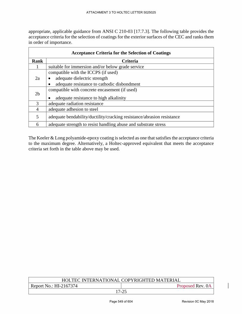
HOLTEC INTERNATIONAL COPYRIGHTED MATERIAL
Report No.: HI-2167374 Proposed Rev. 0A
17-25
appropriate, applicable guidance from ANSI C 210-03 [17.7.3]. The following table provides the
acceptance criteria for the selection of coatings for the exterior surfaces of the CEC and ranks them
in order of importance.
Acceptance Criteria for the Selection of Coatings
Rank Criteria
1 suitable for immersion and/or below grade service
2a
compatible with the ICCPS (if used)
• adequate dielectric strength
• adequate resistance to cathodic disbondment
2b compatible with concrete encasement (if used)
• adequate resistance to high alkalinity
3 adequate radiation resistance
4 adequate adhesion to steel
5 adequate bendability/ductility/cracking resistance/abrasion resistance
6 adequate strength to resist handling abuse and substrate stress
The Keeler & Long polyamide-epoxy coating is selected as one that satisfies the acceptance criteria
to the maximum degree. Alternatively, a Holtec-approved equivalent that meets the acceptance
criteria set forth in the table above may be used.
ATTACHMENT 3 TO HOLTEC LETTER 5025025
Page 549 of 604 Revision 0C May 2018
HOLTEC INTERNATIONAL COPYRIGHTED MATERIAL
Report No.: HI-2167374 Proposed Rev. 0A
17-26
17.8 GAMMA AND NEUTRON SHIELDING MATERIALS
Gamma and neutron shield materials in the HI-STORM UMAX VVM system are discussed in
Section 1.2. The primary shielding materials used in the HI-STORM UMAX VVM system, as
listed in Table 17.1.3, are plain concrete, reinforced concrete, and steel.
The plain concrete provides the main shielding function in the HI-STORM UMAX lids to
minimize sky shine.
17.8.1 Plain Concrete
Unlike the above ground HI-STORM models, the use of plain concrete for shielding purposes in
the underground VVMs is limited to the VVM Closure Lid. The critical characteristics of concrete
used in the Closure Lid are its density and compressive strength. Table 2.3.2 in the HI-STORM
UMAX FSAR provides reference properties of plain concrete used in the Closure Lid.
The density of plain concrete within the HI-STORM UMAX VVM is subject to a minor decrease
due to long-term exposure to elevated temperatures. The reduction in density occurs primarily due
to liberation of unbonded water by evaporation.
ATTACHMENT 3 TO HOLTEC LETTER 5025025
Page 550 of 604 Revision 0C May 2018
HOLTEC INTERNATIONAL COPYRIGHTED MATERIAL
Report No.: HI-2167374 Proposed Rev. 0A
17-27
17.9 NEUTRON ABSORBING MATERIALS
The neutron absorber material is permanently installed inside the Canisters for reactivity control.
Metamic-HT is the neutron absorber material utilized the MPC-37 and MPC-89 -Canisters initially
certified in the HI-STORM FW docket (#72-1032). The properties of Metamic-HT are fully
characterized in the HI-STORM FW FSAR [1.3.7] in Paragraph 1.2.1.4 which is incorporated
herein by reference [see Table 17.0.2].
Because Metamic-HT is enclosed in a helium environment and is subject to no interaction with
the environment, its service life is not subject to attrition in storage.
ATTACHMENT 3 TO HOLTEC LETTER 5025025
Page 551 of 604 Revision 0C May 2018
HOLTEC INTERNATIONAL COPYRIGHTED MATERIAL
Report No.: HI-2167374 Proposed Rev. 0A
17-28
17.10 SEALS
The HI-STORM UMAX VVM assembly does not utilize any gaskets that seal against a large
pressure differential.
The only external gasket used in the system is the soft gasket at the Closure lid-CEC Flange
interface that helps prevent the ingress of moisture and insects (through the small crack that may
exist due to weld distortion in the fabrication of interfacing fabricated steel weldment surfaces)
into the module cavity space.
The Divider shell is sealed against the Closure lid using a pliable, non-organic seal material that is
suitable for long-term ambient air application up to 300 degree F.
BISCO® BF-1000 Extra Soft Cellular Silicone gasket material [17.10.1] is selected as one that
satisfies the acceptance criteria to the maximum degree. The seal/gasket material provides
excellent compressibility, softness, and durability to adapt to various environments, making it an
ideal choice for sealing Closure Lid. It has been used in all HI-STORM UMAX ISFSIs thus far.
Equivalent materials that meet the above criteria are also commercially available.
ATTACHMENT 3 TO HOLTEC LETTER 5025025
Page 552 of 604 Revision 0C May 2018
HOLTEC INTERNATIONAL COPYRIGHTED MATERIAL
Report No.: HI-2167374 Proposed Rev. 0A
17-29
17.11 CHEMICAL AND GALVANIC REACTIONS
The materials used in the HI-STORM UMAX System and all other ITS SSCs are examined to
establish that these materials do not participate in any chemical or galvanic reactions when exposed
to the various environments during all normal operating conditions and off-normal and accident
events. Chemical and galvanic reactions related to the MPC are discussed in Section 8.12 of the
HI-STORM FW FSAR.
The following acceptance criteria for chemical and galvanic reactions are extracted from ISG-15
[17.0.1] for use in HI-STORM UMAX VVM components.
a. The DCSS should prevent the spread of radioactive material and maintain safety control
functions using, as appropriate, noncombustible and heat resistant materials.
b. A review of the DCSS, its components, and operating environments (wet or dry) should
confirm that no operation (e.g., short-term loading/unloading or long-term storage) will
produce adverse chemical and/or galvanic reactions, which could impact the safe use of
the storage cask.
c. Components of the DCSS should not react with one another, or with the cover gas or spent
fuel, in a manner that may adversely affect safety. Additionally, corrosion of components
inside the containment vessel should be effectively prevented.
d. Potential problems from general corrosion, pitting, stress corrosion cracking, or other types
of corrosion, should be evaluated for the environmental conditions and dynamic loading
effects that are specific to the component.
The materials and their ITS pedigree are listed in the drawing package provided in Section 1.5. of
Chapter 1 The compatibility of the selected materials with the operating environment and to each
other for potential galvanic reactions is discussed in this section.
• External atmosphere – During long-term storage the casks are exposed to outside
atmosphere, air with temperature variations, solar radiation, rain, snow, ice, etc.
As discussed herein, the ITS components of the HI-STORM UMAX System and other SSCs have
been engineered to ensure that the environmental conditions expected to exist at nuclear power
plant installations do not prevent the cask components from rendering their respective intended
functions.
The principal operational considerations that bear on the adequacy of the VVM for the service life
are addressed as follows:
Exposure to Environmental Effects
All exposed surfaces of the HI-STORM UMAX VVM components are made from stainless steels
or ferritic steels that are readily painted. The same is true for all the other ITS SSCs and care is
taken to avoid the formation of galvanic cells by deposition of appropriate coatings, as necessary,
in case dissimilar materials are joined together. Concrete, which serves strictly as a shielding
material in the VVM Closure Lid, is encased in steel. Therefore, the potential of environmental
vagaries such as spalling of concrete are ruled out for HI-STORM UMAX VVM. Under normal
storage conditions, the bulk temperature of the HI-STORM UMAX storage overpack will change
ATTACHMENT 3 TO HOLTEC LETTER 5025025
Page 553 of 604 Revision 0C May 2018
HOLTEC INTERNATIONAL COPYRIGHTED MATERIAL
Report No.: HI-2167374 Proposed Rev. 0A
17-30
very gradually with time because of its large thermal inertia. Therefore, material degradation from
rapid thermal ramping conditions is not credible for the HI-STORM UMAX VVM. Similarly,
corrosion of structural steel embedded in the concrete structures due to salinity in the environment
at coastal sites is not a concern for HI-STORM UMAX VVM because it does not rely on rebars
(indeed, it contains no rebars). The configuration of the storage VVM assures resistance to freeze-
thaw degradation. In addition, the storage system is specifically designed for a full range of
enveloping design basis natural phenomena that could occur over the service life of the storage
system as catalogued in Section 2.2 and evaluated in Chapter 15.
The ISFSI pad, which is exposed to the elements, shall be subject to a surveillance program to
monitor its potential degradation, as discussed in Chapter 10.
Material Degradation
The relatively low neutron flux to which the VVM is subjected cannot produce measurable
degradation of the cask's material properties and impair its intended safety function. Exposed
carbon steel components are coated to prevent corrosion. The ambient environment of the ISFSI
storage pad mitigates damage due to exposure to corrosive and aggressive chemicals that may be
produced at other industrial plants in the surrounding area.
Maintenance and Inspection Provisions
The requirements for periodic inspection and maintenance of all the ITS SSCs at HI-STORE CIS
facility throughout their service life is defined in Chapter 10. These requirements include
provisions for routine inspection of the exterior surfaces of equipment and periodic visual
verification that the ventilation flow paths are free and clear of debris in the VVM. In addition,
the HI-STORM UMAX system is designed for easy retrieval of the MPC from the VVM should it
become necessary to perform more detailed inspections and repairs on the storage system.
The above findings are consistent with those of the NRC's Continued Storage of Spent Nuclear
Fuel Decision [17.11.1], which concluded that dry storage systems designed, fabricated, inspected,
and operated in accordance with such requirements are adequate for the design and service life
expectations set down in Table 17.0.1.
ATTACHMENT 3 TO HOLTEC LETTER 5025025
Page 554 of 604 Revision 0C May 2018
HOLTEC INTERNATIONAL COPYRIGHTED MATERIAL
Report No.: HI-2167374 Proposed Rev. 0A
17-31
17.12 FUEL CLADDING INTEGRITY
The discussion related to the fuel cladding integrity during short term operations is incorporated
by reference from Section 8.13 of the HI-STORM FW FSAR and is not repeated here.
ATTACHMENT 3 TO HOLTEC LETTER 5025025
Page 555 of 604 Revision 0C May 2018
HOLTEC INTERNATIONAL COPYRIGHTED MATERIAL
Report No.: HI-2167374 Proposed Rev. 0A
17-32
17.13 EXAMINATION AND TESTING
Examination and testing are integral parts of manufacturing of the HI-STORM UMAX System
and other ITS components that will be used at the HI-STORE CIS facility. The requirements for
HI-STORM UMAX system are incorporated by reference from HI-STORM UMAX FSAR [1.0.6],
Section 8.13.
Post-fabrication inspections are discussed in Chapter 10 of this SAR as part of the HI-STORM
UMAX VVM System maintenance program. Inspections are conducted prior to fuel loading or
prior to each fuel handling campaign. Other periodic inspections are conducted during storage.
The HI-STORM UMAX VVM is a passive device with no moving parts. The vent screens are
inspected on scheduled intervals for damage, holes, etc. All the other ITS SSCs are inspected per
scheduled intervals (Table 18.6.1) for general corrosion and/or mechanical damage.
The external surface of the VVM and the other ITS SSCs at the site, including identification
markings, is visually examined on a periodic basis in accordance with the ISFSI’s surveillance
plan. The temperature monitoring system, if used, is inspected per the licensee’s QA program and
manufacturer’s recommendations.
ATTACHMENT 3 TO HOLTEC LETTER 5025025
Page 556 of 604 Revision 0C May 2018
HOLTEC INTERNATIONAL COPYRIGHTED MATERIAL
Report No.: HI-2167374 Proposed Rev. 0A
17-33
17.14 REGULATORY COMPLIANCE
The preceding sections describe the materials used in important-to-safety SSCs and the suitability
of those materials for their intended functions in the HI-STORM UMAX System at the HI-STORE
CIS facility.
The requirements of 10CFR72.122(a) are met: The material properties of SSCs important to safety
conform to quality standards commensurate with their safety functions.
The requirements of 10CFR72.104(a), 106(b), 124, and 128(a)(2) are met: Materials used for
shielding are adequately designed and specified to perform their intended function.
The requirements of 10CFR72.122(h)(1) are met: The design of the DCSS and the selection of
materials adequately protect the spent fuel cladding against degradation that might otherwise lead
to gross rupture of the cladding by ensuring that the cladding temperature remains below the ISG-
11 Rev 3 limits.
The requirements of 10CFR72.122(l) are met: The material properties of SSCs important-to-safety
will be maintained during normal, off-normal, and accident conditions of operation as well as
short-term operations so the spent fuel can be readily retrieved without posing operational safety
problems.
The requirements of 10CFR72.122(f) are met: The material properties of SSCs important-to-safety
will be maintained during all conditions of operation so the spent fuel can be safely stored for the
specified service life and maintenance can be conducted as required.
The requirements of 10CFR72.1226(b) are met: The HI-STORM UMAX System employs
materials that are not vulnerable to degradation over time or react with one another during long-
term storage.
ATTACHMENT 3 TO HOLTEC LETTER 5025025
Page 557 of 604 Revision 0C May 2018
HOLTEC INTERNATIONAL COPYRIGHTED MATERIAL
Report No. HI-2167374 Proposed Rev. 0A
18-1
CHAPTER 18: AGING MANAGEMENT PROGRAM
18.0 INTRODUCTION
This chapter contains the essentials of the Aging Management Programs (AMP) for the HI-STORE
CIS ISFSI which is intended to possess a long Service life (Table 17.0.1). An effective AMP is
considered an imperative for an ISFSI that may ultimately house thousands of canisters containing
spent nuclear fuel. For such a facility, a well-construed program to thwart gradual weakening of
the safety margins associated with aging of the facility with potentially adverse consequences to
important-to-safety structures, systems and components (SSCs) is a necessity. AMPs monitor and
control the degradation of storage system’s SSCs, so that the aging effects will not result in loss
of their safety-significant function during their service life in interim storage. An effective AMP
prevents, mitigates, or detects the aging effects and provides for the prediction of the extent of the
effects of aging and timely corrective actions before there is a loss of intended function.
It is recognized that the HI-STORE ISFSI will store canisters most of whom have been previously
stored at an ISFSI at an operating or shuttered nuclear plant site. An AMP has not been required
as a part of the initial licensing cycle of an ISFSI which has historically been 20 years. An
acceptable AMP is required, however, at the end of the initial licensed life as a regulatory predicate
for life extension of the storage license. At HI-STORE CIS, Holtec International plans to
implement a state-of-the-art AMP that incorporates certain innovative approaches pioneered by
the Company which are founded on the fundamentals of material degradation mechanisms. The
architecture of the Program is informed by the published regulatory and industry literature as
synopsized below.
NUREG-1927 [18.0.1] sets down an AMP containing 10 elements to manage the effects of aging.
This document emphasizes the operating experience of all operating units to be documented and
reviewed. Periodic future reviews of operating experience are required to confirm the effectiveness
of AMP, or identify a need to enhance/modify the AMP. Managing aging mechanisms and effects
in a “learning” manner articulated in [18.0.1] means ISFSI owners would monitor both the known
SSC degradation mechanisms and the symptoms that would be indicators of a potential unknown
SSC degradation mechanism.
The AMP set down in this chapter consists of four major components, namely
• Monitoring for emerging signs of potential degradation
• Periodic inspection and testing to uncover onset of the SSC’s degradation
• Implementation of preventive measures (barriers) to arrest degradation
• Recovery and remedial measures if all barriers were to fail
Each of the above constituents of the AMP is summarized in the following sections.
All references are in placed within square brackets in this report and are compiled in Chapter 19 (last chapter)
ATTACHMENT 3 TO HOLTEC LETTER 5025025
Page 558 of 604 Revision 0C May 2018
HOLTEC INTERNATIONAL COPYRIGHTED MATERIAL
Report No. HI-2167374 Proposed Rev. 0A
18-2
Nuclear Energy Institute (NEI) publication #14-03, Revision 1 [18.0.2] elaborates on [18.0.1]
providing an explicit set of expectations from a well implemented AMP. The NEI espoused
program calls for the AMP to have the following attributes:
• safety-focused
• operations-based
• implemented within existing corrective action and operating experience programs
• qualitatively risk-informed based on relevant failure modes and effects
• forward-looking
• proactive
• responsive to condition-based monitoring.
NEI 14-03 [18.0.2] provides a framework for AMP through the use of tollgates, defined as periodic
points within the period of extended operation when licensees would be required to evaluate
aggregate feedback and perform and document a safety assessment that confirms the safe storage
of spent fuel. Tollgates are an additional set of in-service assessments beyond the normal continual
assessment of operating experience, research, monitoring, and inspections on component
performance that is part of normal ISFSI operations for licensees during the initial license period
as well as the renewal period.
The concept of operations-based aging management is to manage aging mechanisms and
timeframes (duration to loss of intended function) that are either not known or not well understood.
Known aging mechanisms will be managed using existing corrective action and operating
experience programs with the objective of preventing loss of intended safety functions due to aging
effects. Because some postulated aging mechanisms and/or timeframes for in-scope SSCs are not
well-characterized by operating data, aging management should be implemented in a manner that
feeds information back in a timely fashion to the licensees. This feedback will be used to perform
corrective actions on components to preclude the loss of safety function over the renewed operating
period.
Operations-based aging management programs should include the following attributes for the
known and unknown degradation mechanisms and time frames:
• recognition and evaluation (key technical issues)
• storage system inspections
• monitoring and operational inspections
• analysis and assessment
• tollgate assessment
• feedback and corrective actions (mitigation/repair and/or analysis).
ATTACHMENT 3 TO HOLTEC LETTER 5025025
Page 559 of 604 Revision 0C May 2018
HOLTEC INTERNATIONAL COPYRIGHTED MATERIAL
Report No. HI-2167374 Proposed Rev. 0A
18-3
The AMP outlined in this chapter incorporates the above elements of [18.0.1 and 18.0.2] and is
termed a “progressively enhanced plan” (PEP) that is shaped and guided by fundamental technical
principles and ongoing operating experience.
All the important-to-safety (ITS) SSCs scoped for aging management were granted a 20 year initial
license under the HI-STORM UMAX license. HI-STORE SAR will be requesting a 40 year
license. To ensure an uninterrupted performance of these ITS SSCs and their intended functions
through the 40 year license period, all such ITS SSCs will be inspected and monitored per their
respective AMP, and a concern-free service life of those SSCs will be established. Additional
AMPs are also included for those SSCs that are not part of the HI-STORM UMAX generic license.
Typical aging mechanisms and quantitative and/or qualitative analyses are discussed in Section
18.3 below.
ATTACHMENT 3 TO HOLTEC LETTER 5025025
Page 560 of 604 Revision 0C May 2018
HOLTEC INTERNATIONAL COPYRIGHTED MATERIAL
Report No. HI-2167374 Proposed Rev. 0A
18-4
18.1 SCOPING EVALUATION AND SEVERITY INDEX
The HI-STORE CIS ISFSI consists of (i) the MPC, (ii) the VVM, and (iii) other support SSCs.
These components were evaluated using the two scoping criteria in NUREG-1927 [18.0.1]. In
summary, these criteria are (1) an SSC that is Important to Safety (ITS) or (2) an SSC that supports
SSC safety functions.
Because the canister provides the confinement protection and reactivity control, its AMP is the
most critical activity and is accordingly the central focus of the program. The VVM which includes
the top pad (ISFSI pad) is the other critical component. As a steel and concrete structure that is
limited to providing dose attenuation, the aging management demands on the VVM are different
in nature from those on the MPC and are also somewhat less severe. Furthermore, the top lid
(Closure Lid) of the VVMs is a removable item which can be replaced with a new lid, if needed,
making the aging management demands on it less consequential. (The VVM body is integral to
the ISFSI and cannot be replaced). The HI-TRAC CS transfer cask is used only during loading
operations; it does not store any used Fuel. The AMP for the Transfer cask is accordingly informed
by its functional requirement. An assessment of the VVM, MPCs, HI-TRAC CS Transfer Cask,
ISFSI pad, and other SSCs is documented in [1.2.1] which identifies the necessary inspection and
monitoring activities to provide reasonable assurance that the SSCs will perform their intended
functions for the duration of their License life. A summary of the SSCs that warrant an AMP along
with the severity of the consequence of each SSC’s degradation is provided in Table 18.1.1
(partially adapted from [1.2.1]). The Severity index is essentially a graded approach to defining
AMP requirements: A Severity Index of 3 is the highest, 2 means moderate severity, 1 is minor
impact on SSC, and 0 means the SSC is not subject to an AMP.
ATTACHMENT 3 TO HOLTEC LETTER 5025025
Page 561 of 604 Revision 0C May 2018
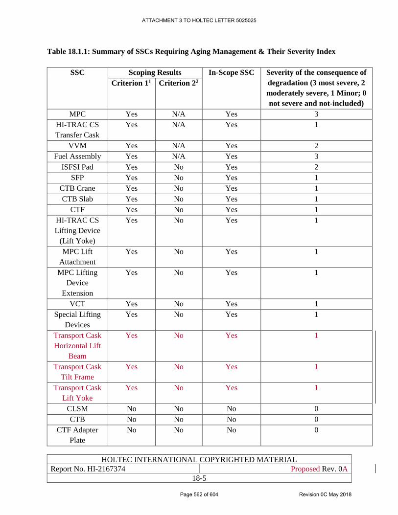
HOLTEC INTERNATIONAL COPYRIGHTED MATERIAL
Report No. HI-2167374 Proposed Rev. 0A
18-5
Table 18.1.1: Summary of SSCs Requiring Aging Management & Their Severity Index
SSC Scoping Results In-Scope SSC Severity of the consequence of
degradation (3 most severe, 2
moderately severe, 1 Minor; 0
not severe and not-included)
Criterion 11 Criterion 22
MPC Yes N/A Yes 3
HI-TRAC CS
Transfer Cask
Yes N/A Yes 1
VVM Yes N/A Yes 2
Fuel Assembly Yes N/A Yes 3
ISFSI Pad Yes No Yes 2
SFP Yes No Yes 1
CTB Crane Yes No Yes 1
CTB Slab Yes No Yes 1
CTF Yes No Yes 1
HI-TRAC CS
Lifting Device
(Lift Yoke)
Yes No Yes 1
MPC Lift
Attachment
Yes No Yes 1
MPC Lifting
Device
Extension
Yes No Yes 1
VCT Yes No Yes 1
Special Lifting
Devices
Yes No Yes 1
Transport Cask
Horizontal Lift
Beam
Yes No Yes 1
Transport Cask
Tilt Frame
Yes No Yes 1
Transport Cask
Lift Yoke
Yes No Yes 1
CLSM No No No 0
CTB No No No 0
CTF Adapter
Plate
No No No 0
ATTACHMENT 3 TO HOLTEC LETTER 5025025
Page 562 of 604 Revision 0C May 2018
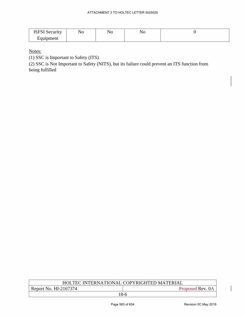
HOLTEC INTERNATIONAL COPYRIGHTED MATERIAL
Report No. HI-2167374 Proposed Rev. 0A
18-6
ISFSI Security
Equipment
No No No 0
Notes:
(1) SSC is Important to Safety (ITS)
(2) SSC is Not Important to Safety (NITS), but its failure could prevent an ITS function from
being fulfilled
ATTACHMENT 3 TO HOLTEC LETTER 5025025
Page 563 of 604 Revision 0C May 2018
HOLTEC INTERNATIONAL COPYRIGHTED MATERIAL
Report No. HI-2167374 Proposed Rev. 0A
18-7
18.2 MAINTENANCE PROGRAM FOR THE HI-STORM UMAX VVM &
HI-TRAC CS
The maintenance program is an essential element of a comprehensive AMP. The essentials of the
maintenance program for the HI-STORE ISFSI SSCs are summarized in Chapter 10. The
relationship of aging management to the maintenance program is discussed in Section 18.13.
ATTACHMENT 3 TO HOLTEC LETTER 5025025
Page 564 of 604 Revision 0C May 2018
HOLTEC INTERNATIONAL COPYRIGHTED MATERIAL
Report No. HI-2167374 Proposed Rev. 0A
18-8
18.3 MECHANISMS FOR AGING OF SSCS
In this section, the fundamental mechanisms that underlie aging of a dry storage SSC are
summarized to serve as the guide in evolving an effective aging management program. The
principal effects that can cause aging of an SSC are:
i. Cyclic fatigue from thermal and pressure transients
ii. Creep
iii. Erosion
iv. General Corrosion
v. Boron depletion (of neutron absorbing or shielding materials)
vi. Crack propagation
vii. Repetitive mechanical loading (of trunnions and threaded anchor locations)
viii. Stress corrosion cracking (SCC)
Each mechanism is discussed below in the context of its potential role in aging of the HI-STORE
SSCs.
i. Cyclic Fatigue:
Cyclic fatigue is caused by thermal or pressure transients in a SSC. The necessary condition for
fatigue expenditure in metals is a rapid pulsation of large amplitude stress which is only possible
in the dry storage SSCs if the environmental conditions were to change drastically (hundreds of °F
change) in a matter of seconds and such changes were to occur repeatedly (thousands of cycles).
Because such cyclic conditions are not realistic for any terrestrial environment, cyclic fatigue of
dry storage components and structures is not a credible mechanism for their degradation.
Quantitative analysis of long term fatigue on HI-TRAC CS, Transport Cask lift beams and other
lifting ancillaries (lift yokes, etc.) is discussed in Chapter 5 of this SAR.
It summarizes a cyclic loading fatigue evaluation of the HI-TRAC CS Transfer Cask, Transport
Cask lift beams and other lifting ancillaries which concludes that stresses are well below the
endurance limit of the trunnion material. Thus, trunnion fatigue is not an issue during the aging
management period. It is conservatively assumed that the HI-TRAC CS, Transport Cask lift beams
and other lifting ancillaries are utilized for all lifts of the ISFSI MPCs. However, the allowable
number of lifting cycles far exceeds the number of lifts that will be needed. Therefore, no
additional aging management plan is needed to address fatigue failure of the HI-TRAC CS,
Transport Cask lift beams and other lifting ancillaries.
The Transport Cask Tilt Frame is not a lifting device since it is a stationary device that provides
support to the cask from below. Also, during upending or down ending operations, the cask always
remains connected to the single failure proof CTB Crane via a special lifting device. Structural
analysis of tilt frame is summarized in Chapter 5 of this SAR.
ii. Creep:
ATTACHMENT 3 TO HOLTEC LETTER 5025025
Page 565 of 604 Revision 0C May 2018
HOLTEC INTERNATIONAL COPYRIGHTED MATERIAL
Report No. HI-2167374 Proposed Rev. 0A
18-9
Creep is a time-dependent effect that produces ever-increasing deformation under a sustained load.
Creep is a factor in components that operate at a high temperature and are subject to an elevated
state of stress. Creep effects are negligible in most metals at moderate temperature (below 600°F)
and stress levels (less than half of the material's Yield Strength). Creep, therefore, is a concern
only for the fuel assembly rods inside the canisters. Because the fuel rods are thin walled
pressurized tubes and operate at elevated temperatures, the incidence of damage from creep cannot
be ruled out. In this respect, the high thermal capacity of the HI-STORM UMAX system provides
an effective protection against creep. A quantitative estimate of the benefit accrued by HI-STORM
UMAX to the canisters brought in at a substantially lower heat load (Section 4.1) can be obtained
by using the creep rate equation for fuel cladding from [18.3.1]:
[
PROPRIETARY INFORMATION WITHHELD IN ACCORDANCE WITH
10CFR2.390
]
The creep rate corresponding to the maximum heat load in HI-STORM UMAX to that if the fuel
rod were at the ISG-11 Rev 3 limit temperature can be obtained by assuming the cladding hoop
stress is directly proportional to the absolute temperature of the cladding material. Using the
cladding temperature result from Table 18.3.1, the ratio is determined and presented in Table
18.3.1. As can be seen from this result, the high thermal capacity of the HI-STORM VVMs has
the effect of reducing the creep rate by several orders of magnitude.
Of course, as the canister ages, its heat load decreases, causing a corresponding decrease in the
creep rate, reaching vanishing small values after a few years. Therefore, the threat of creep damage
to the fuel recedes to a negligible range as the canisters will age in interim storage at HI-STORE.
Appendix D of NUREG-1927 [18.0.1] provides supplemental guidance for the use of a
demonstration program as a surveillance tool for confirmation of integrity of High Burnup Fuel
(HBF) during the period of extended operation. The technical discussion and guidance provided
by the demonstration program will be used for learning purposes and the results obtained from the
program will be analyzed. All appropriate actions shall be taken at the HI-STORE facility, as
needed, based on the demonstration program results.
ATTACHMENT 3 TO HOLTEC LETTER 5025025
Page 566 of 604 Revision 0C May 2018
HOLTEC INTERNATIONAL COPYRIGHTED MATERIAL
Report No. HI-2167374 Proposed Rev. 0A
18-10
iii. Erosion:
Erosion is a mechanical action wherein the impinging particles carried by a fluid medium on a
surface causes the target surface to release fine surface matter. Erosion requires a high fluid
velocity to cause noticeable material loss. Contemporary design practice in tubular heat exchanger
thermal design holds that the incident velocity must be high enough so that E defined by ρv2 >
500, where ρ is density of the fluid carrier in lb/cubic feet, and v is the flow velocity orthogonal to
the target surface in feet/sec.
The evident area on the canister’s surface potentially vulnerable to erosion would be the surface
facing the inlet ducts through which ventilation air enters. The value of in-duct air velocity from
the FLUENT analysis is used for comparison purposes. The key computed data is summarized in
the unnumbered table below which shows that the minimum required threshold value is orders of
magnitude larger than the actual value.
Empirical correlation for the rate of erosion states that the rate varies as 4.5 power of velocity.
Using this correlation gives the computed factor of safety against the onset of erosion on the
canister’s surface.
[
PROPRIETARY INFORMATION WITHHELD IN ACCORDANCE WITH 10CFR2.390
]
Therefore, erosion is ruled out as an actuating mechanism to cause damage to the stored canister
at the HI-STORE facility.
iv. General Corrosion & Spalling of the ISFSI concrete surface:
General corrosion of painted carbon steel surfaces in the HI-STORE CIS is expected and dealt
with in the maintenance program described in the foregoing. Because the ambient air is relatively
dry, the incidence of peeling of the coating is expected to be much more subdued.
Likewise spalling of the ISFSI concrete surface around the VVM is prevented by keeping the
surface coating in good condition through preventive maintenance.
v. Boron depletion:
The theoretical risk of boron depletion applies to the neutron absorber panels in the canister's Fuel
Basket wherein the B-10 isotope in the material serves to capture thermalized neutrons produced
by the radioactive decay of the used fuel. Calculations performed on a typical canister show that
ATTACHMENT 3 TO HOLTEC LETTER 5025025
Page 567 of 604 Revision 0C May 2018
HOLTEC INTERNATIONAL COPYRIGHTED MATERIAL
Report No. HI-2167374 Proposed Rev. 0A
18-11
the fraction of boron atoms consumed during the service life of the MPC (Table 17.0.1) will be a
small fraction of boron available in the Fuel Basket.
A quantitative analysis on Boron depletion has been discussed in Section 3.4.8 of HI-STORM FW
FSAR [1.3.7]. The analysis demonstrates that the Boron depletion in Metamic-HT material is
negligible over a 60 year duration. Thus, sufficient levels of Boron are present in the fuel basket
neutron absorbing material to maintain criticality safety functions over the license life of the MPC.
Therefore, aging management of the canister to insure adequate boron-10 isotope in the Fuel
Basket is not necessary; the canister does not run a credible risk of boron depletion below the
needed level to maintain subcriticality.
vi. Crack propagation:
Every material has flaws at microscopic level. Those components whose load bearing materials
are volumetrically examined are less apt to have hidden flaws but the existence of imperfections
that can propagate over time can't be entirely ruled out. In order to ensure that any pre-existing
flaw will not propagate and lead to sudden failure, the following design measures will be
implemented in the design and manufacturing of the SSCs for HI-STORE:
• In high strength materials, such as those used in lift rigs, the maximum primary stress in
the material during lifting and handling operations is required to be less than 1/6th of the
material Yield Strength which is generally considered to be the limit at which a pre-existing
crack may propagate.
• In high ductility materials, such as austenitic stainless steel (used in the canister), the
maximum stress is required to meet the limit in Reg Guide 3.61. Furthermore, the primary
stress in the canister under normal storage condition is required to meet the limit for ASME
Section III Class 1 components.
Observing the above restrictions eliminates the threat of crack propagation in critical equipment
at the HI-STORM ISFSI and hence the need for any prophylactic measures to avoid their
occurrence.
vii. Repetitive Mechanical Loading:
The design measure employed by Holtec requires the maximum primary stress in a trunnion or
threaded anchor location under the maximum lifted load to be below the “endurance strength” of
the material. Observing the endurance limit criterion eliminates the threat of cyclic fatigue failure
a’ priori. Quantitative analysis of long term fatigue on lifting ancillaries is discussed in Chapter 5
in the SAR.
viii. Stress Corrosion Cracking (SCC):
Unique to austenitic and duplex stainless steels, SCC causes cracking at the intergranular or
transgranular level in the material. It is a serious threat to the canister's confinement boundary
which is exposed to the ambient environment at the ISFSI. The incidence of SCC requires three
essential conditions to be present concurrently:
a. Significant tensile stress at the surface exposed to the environment, and
b. Halides in the environment, and
ATTACHMENT 3 TO HOLTEC LETTER 5025025
Page 568 of 604 Revision 0C May 2018
HOLTEC INTERNATIONAL COPYRIGHTED MATERIAL
Report No. HI-2167374 Proposed Rev. 0A
18-12
c. Relative humidity in excess of 20%
At the HI-STORE site, the halide content in the air is negligible as mentioned in Chapter 2,
therefore an essential requirement for SCC is not satisfied and the incidence of SSC becomes a
remote possibility. Nevertheless, the risk of SCC cannot be entirely ruled out and the AMP must
provide for a way to anticipate it. Accordingly, the monitoring method for the canister proposed
in this SAR assumes that the threat of SCC is real and possible.
ATTACHMENT 3 TO HOLTEC LETTER 5025025
Page 569 of 604 Revision 0C May 2018
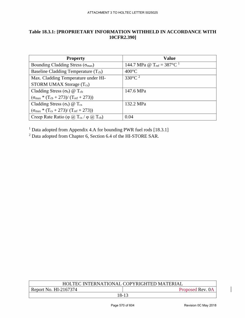
HOLTEC INTERNATIONAL COPYRIGHTED MATERIAL
Report No. HI-2167374 Proposed Rev. 0A
18-13
Table 18.3.1: [PROPRIETARY INFORMATION WITHHELD IN ACCORDANCE WITH
10CFR2.390]
Property Value
Bounding Cladding Stress (σmax) 144.7 MPa @ Tref = 387°C 1
Baseline Cladding Temperature (Tcb) 400°C
Max. Cladding Temperature under HI-
STORM UMAX Storage (Tcs)
330°C 2
Cladding Stress (σb) @ Tcb
(σmax * (Tcb + 273)/ (Tref + 273))
147.6 MPa
Cladding Stress (σs) @ Tcs
(σmax * (Tcs + 273)/ (Tref + 273))
132.2 MPa
Creep Rate Ratio (φ @ Tcs / φ @ Tcb) 0.04
1 Data adopted from Appendix 4.A for bounding PWR fuel rods [18.3.1] 2 Data adopted from Chapter 6, Section 6.4 of the HI-STORE SAR.
ATTACHMENT 3 TO HOLTEC LETTER 5025025
Page 570 of 604 Revision 0C May 2018
HOLTEC INTERNATIONAL COPYRIGHTED MATERIAL
Report No. HI-2167374 Proposed Rev. 0A
18-14
18.4 UNIQUE ASPECTS OF THE HI-STORE CIS WITH NEXUS TO ITS
AMP
The following aspects of the HI-STORE ISFSI are relevant to developing a sound AMP for the
site:
i. Because the storage system is subterranean, the extent of the exposed metal surface of the
VVM is quite small compared to the above-ground storage systems.
ii. The relatively thin wall of the exposed surface of the canister (the canister's shell which is
made of austenitic stainless steel) is disposed vertically which, as expected, discourages
the deposition of aggressive species from accumulating on the shell surface. (An
EPRI/Holtec measurement program at Diablo Canyon and Salem/Hope Creek ISFSIs
showed that the deposition on the shell surface is significantly less than that on the
horizontal surface [18.4.1]). It is well known that the deposition of solutes on the surface
of stainless steel directly correlates with the risk of generation of nucleation sites where
stress corrosion cracking (SCC) may initiate. Reduced deposition rate on the thin wall of
the canister is a positive feature for an extended service life.
iii. As described in Chapter 2, the ambient environment at the HI-STORE site has minuscule
amount of salts and other airborne particulates known to be injurious to stainless steel. The
minuscule concentration of halides in the air starves the canister's surface of an essential
ingredient for initiating SCC.
iv. There is no location for contaminant hide-out (such as crevice or gouge) on the surface of
the vertically arrayed canister (in contrast to the condition where the canister is horizontally
stored), where halide-bearing particles may concentrate enabling SCC to take hold.
v. The settling of moisture on the canister's shell during cool hours followed by warm hours
causing the moisture to evaporate leaving behind the particulate residue is the principal
means for salts to accumulate on the canister's surface. In the high desert of south-eastern
New Mexico, the relative humidity in the air is low, making the delivery of salts to the
canister's surface less effective.
In light of the above, it is reasonable to expect that the canisters stored at HI-STORE CIS will
have a substantially longer service life than that projected in Table 17.0.1. Nevertheless, a
progressively enhanced plan for Aging Management has been adopted in this SAR as explained
in this Chapter.
ATTACHMENT 3 TO HOLTEC LETTER 5025025
Page 571 of 604 Revision 0C May 2018
HOLTEC INTERNATIONAL COPYRIGHTED MATERIAL
Report No. HI-2167374 Proposed Rev. 0A
18-15
18.5 CANISTER AGING MANAGEMENT PROGRAM
The welded canisters need inspections and enhanced monitoring programs in order to detect
potential chloride-induced stress corrosion cracking (CISCC) initiation and propagation prior to
through wall growth. To identify SCC in canisters at HI-STORE CIS prior to a loss of function, a
set of criteria and associated canister ranking values will be developed per EPRI Report [18.5.1].
This ranking may be used to assess welded MPCs at the site with regard to selecting more
susceptible canisters for inspections .
[18.5.1] also mentions additional factors that should be considered for prioritizing canisters among
a population of canisters with the same rank. The canister ranking criteria are designed to rank
individual canisters at HI-STORE site based on the anticipated level of chloride accumulation, the
contribution of the material alloy to CISCC susceptibility, and the surface regions where
deliquescence could occur. The chloride accumulation/deposition criterion provides a rank factor
based on the previous site and the time elapsed since the canister was emplaced in the overpack.
The material criterion provides a ranking factor based on resistance to SCC. The decay heat
criterion provides a ranking factor relating current canister residual decay heat to the prevalence
of deliquescent conditions on the canister surface using surface temperatures from available
thermal models. The results of the canister ranking will be used in the canister inspection selection
criteria and in the development of the learning based AMP/operating experience.
18.5.1 Visual Examination
The canister AMP involves monitoring the exterior surface of a MPC, including visual inspection
of the MPC surface for signs of degradation. The canisters with the highest susceptibility for SCC
should be selected for inspection. The selection criteria include oldest and coldest canisters with a
potential for accumulation and deliquescence of deposited salts that may promote localized
corrosion and/or SCC. The selection criteria for inspection of the installed canisters at the site will
be re-evaluated as and when additional canisters are installed. The visual inspection frequency has
been outlined per Table 18.6.1. All the accessible weld areas of the canister(s) will be covered for
SCC inspection/monitoring and the canisters selected for inspection will be visually inspected for
conditions listed below.
The monitored conditions include, but are not limited to:
• Localized corrosion pits, stress corrosion cracking, etching, or deposits
• Discrete colored corrosion products, especially those adjacent to welds and weld heat
affected zones
• Linear appearance of corrosion products parallel to or traversing welds or weld heat
affected zones
• Red-orange colored corrosion products combined with deposit accumulations in any
location
• Red-orange colored corrosion tubercles of any size
ATTACHMENT 3 TO HOLTEC LETTER 5025025
Page 572 of 604 Revision 0C May 2018
HOLTEC INTERNATIONAL COPYRIGHTED MATERIAL
Report No. HI-2167374 Proposed Rev. 0A
18-16
18.5.2 Accelerated Coupon Testing
[
PROPRIETARY INFORMATION WITHHELD IN ACCORDANCE WITH 10CFR2.390
]
[
PROPRIETARY INFORMATION WITHHELD IN ACCORDANCE WITH 10CFR2.390
]
ATTACHMENT 3 TO HOLTEC LETTER 5025025
Page 573 of 604 Revision 0C May 2018
HOLTEC INTERNATIONAL COPYRIGHTED MATERIAL
Report No. HI-2167374 Proposed Rev. 0A
18-17
Figure 18.5.1: [PROPRIETARY INFORMATION WITHHELD IN ACCORDANCE
WITH 10CFR2.390]
ATTACHMENT 3 TO HOLTEC LETTER 5025025
Page 574 of 604 Revision 0C May 2018
HOLTEC INTERNATIONAL COPYRIGHTED MATERIAL
Report No. HI-2167374 Proposed Rev. 0A
18-18
Figure 18.5.2: [PROPRIETARY INFORMATION WITHHELD IN
ACCORDANCE WITH 10CFR2.390]
ATTACHMENT 3 TO HOLTEC LETTER 5025025
Page 575 of 604 Revision 0C May 2018
HOLTEC INTERNATIONAL COPYRIGHTED MATERIAL
Report No. HI-2167374 Proposed Rev. 0A
18-19
18.6 HI-TRAC CS TRANSFER CASK AGING MANAGEMENT
PROGRAM
The HI-TRAC CS Transfer Cask Aging Management Program utilizes inspections to ensure that
the transfer cask maintains its intended function throughout its Service Life by performing a visual
inspection for degradation of the external surfaces of the Transfer Cask and trunnions. This
inspection is performed prior to use of the Transfer Cask per Table 18.6.1.
The visual inspection will include the following:
• All painted surfaces for corrosion and paint integrity
• All surfaces for dents, scratches, gouges, or other damage
• Lifting trunnions for deformation, cracks, damage, corrosion, and galling
ATTACHMENT 3 TO HOLTEC LETTER 5025025
Page 576 of 604 Revision 0C May 2018
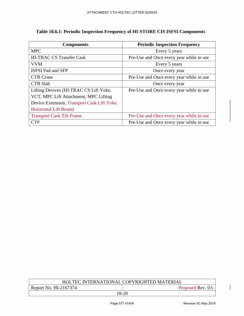
HOLTEC INTERNATIONAL COPYRIGHTED MATERIAL
Report No. HI-2167374 Proposed Rev. 0A
18-20
Table 18.6.1: Periodic Inspection Frequency of HI-STORE CIS ISFSI Components
Components Periodic Inspection Frequency
MPC Every 5 years
HI-TRAC CS Transfer Cask Pre-Use and Once every year while in use
VVM Every 5 years
ISFSI Pad and SFP Once every year
CTB Crane Pre-Use and Once every year while in use
CTB Slab Once every year
Lifting Devices (HI-TRAC CS Lift Yoke,
VCT, MPC Lift Attachment, MPC Lifting
Device Extension, Transport Cask Lift Yoke,
Horizontal Lift Beam)
Pre-Use and Once every year while in use
Transport Cask Tilt Frame Pre-Use and Once every year while in use
CTF Pre-Use and Once every year while in use
ATTACHMENT 3 TO HOLTEC LETTER 5025025
Page 577 of 604 Revision 0C May 2018
HOLTEC INTERNATIONAL COPYRIGHTED MATERIAL
Report No. HI-2167374 Proposed Rev. 0A
18-21
18.7 VVM AGING MANAGEMENT PROGRAM
The Vertical Ventilated Module (VVM) AMP utilizes condition monitoring to manage aging
effects of the Cavity Enclosure Container (CEC), Divider Shell, and the Closure Lid as set down
in the maintenance program in the foregoing. The initial frequency of inspection is set down in
Table 18.6.1 which is subject to change depending on the ‘tollgate” protocol explained in Section
18.12.
The visual inspection of the steel components and structures will include the following:
• All internal surfaces for corrosion and integrity
• All other surfaces for dents scratches, gouges, or other damage.
ATTACHMENT 3 TO HOLTEC LETTER 5025025
Page 578 of 604 Revision 0C May 2018
HOLTEC INTERNATIONAL COPYRIGHTED MATERIAL
Report No. HI-2167374 Proposed Rev. 0A
18-22
18.8 REINFORCED CONCRETE AGING MANAGEMENT PROGRAM
The ISFSI pad, SFP and Cask Transfer Building (CTB) slab are examples of reinforced concrete
structures at the HI-STORE CIS facility. The AMP includes periodic visual inspections by
personnel qualified to monitor reinforced concrete for applicable aging effects, and evaluate
identified aging effects against acceptance criteria derived from the design bases. The initial
frequency of inspection is set down in Table 18.6.1.
The program also includes periodic sampling and testing of groundwater, and the need to assess
the impact of any changes in its chemistry on the concrete structures underground. Additional
activities may include periodic inspections to ensure the air convection vents are not blocked.
The inspection of the reinforced concrete structures will include the following:
• All accessible surfaces for cracking, loss of material, permeability and integrity
• Groundwater chemistry monitoring to identify conditions conducive to underground aging
mechanisms such as corrosion of steel and degradation due to chemical attack.
ATTACHMENT 3 TO HOLTEC LETTER 5025025
Page 579 of 604 Revision 0C May 2018
HOLTEC INTERNATIONAL COPYRIGHTED MATERIAL
Report No. HI-2167374 Proposed Rev. 0A
18-23
18.9 HBF AGING MANAGEMENT PROGRAM
This is a program that monitors and assesses data and other information regarding HBF
performance, to confirm that the design-bases HBF configuration is maintained during the period
of extended operation. The HBF AMP relies on a surrogate demonstration program to provide data
on HBF performance. Guidance to support HBF AMP is given in Appendix D of NUREG-1927.
The aging management review is not expected to identify any aging effects that could lead to fuel
reconfiguration, as long as the HBF is stored in a dry inert environment, temperature limits are
maintained, and thermal cycling is limited. Short term testing and scientific analyses examining
the performance of HBF have provided a foundation for the technical basis that storage of HBF in
the period of extended operation may be performed safely and in compliance with regulations.
However, there has been relatively little operating experience, to date, with dry storage of HBF.
Therefore, the purpose of HBF AMP is to monitor and assess data and other information regarding
HBF performance to confirm there is no degradation of HBF that would result in an unanalyzed
configuration during the period of extended operation.
The parameters (maximum assembly-average burnup, cladding type, peak cladding temperatures)
of the demonstration program are applicable to the design-bases HBF at HI-STORE.
18.10 LIFTING DEVICE AGING MANAGEMENT PROGRAM
ATTACHMENT 3 TO HOLTEC LETTER 5025025
Page 580 of 604 Revision 0C May 2018
HOLTEC INTERNATIONAL COPYRIGHTED MATERIAL
Report No. HI-2167374 Proposed Rev. 0A
18-24
Ancillaries for the HI-STORE CIS are equipment, systems or devices that are needed to carry out
Short Term Operations to place the canister into interim storage or to remove the loaded canister
from storage. The lifting and handling ancillaries needed for operation of the HI-STORE CIS are
classified as either “lifting devices” or “special lifting devices”. The design requirements and stress
compliance criteria applicable for such devices are located in Section 4.5 of this SAR.
The term lifting device as used in this SAR refers to components of a lifting and handling system
that are not classified as special lifting devices. ANSI N14.6 is not applicable to these lifting
devices. Examples of lifting devices used with Holtec’s systems include the VCT used in the
transport cask receiving area of the Cask Transfer Building (CTB).
The term special lifting device refers to components to which ANSI N14.6 [1.2.4] applies. As
stated in ANSI N14.6 (both 1978 and 1993 versions), “This standard shall apply to special lifting
devices that transmit the load from lifting attachments, which are structural parts of a container to
the hook(s) of an overhead hoisting system.” Examples of special lifting devices are canister lift
cleats, cask lift brackets, and HI-TRAC CS Lifting Device (Lift Yoke) , Transport Cask Lift Yoke
and Transport Cask Horizontal Lift Beam..
The Lifting Device AMP utilizes condition monitoring to manage aging effects of the Cask
Transfer Building (CTB) Crane, Canister Transfer Facility (CTF), Vertical Cask Transporter (VCT),
MPC Lift Attachment, MPC Lifting Device Extension, HI-TRAC CS Lift Yoke and Special Lifting
Devices, Transport Cask Lift Yoke and Horizontal Lift Beam as set down in the maintenance
program in the foregoing. The initial frequency of inspection is set down in Table 18.6.1 which is
subject to change depending on the ‘tollgate” protocol explained in Section 18.12.
The visual inspection of the steel components and structures will include the following:
• All internal surfaces for corrosion and integrity
• All other surfaces for dents scratches, gouges, or other damage.
ATTACHMENT 3 TO HOLTEC LETTER 5025025
Page 581 of 604 Revision 0C May 2018
HOLTEC INTERNATIONAL COPYRIGHTED MATERIAL
Report No. HI-2167374 Proposed Rev. 0A
18-25
18.11 TILT FRAME AGING MANAGEMENT PROGRAM
The Tilt Frame AMP utilizes condition monitoring to manage aging effects of the Transport Cask
Tilt Frame as set down in the maintenance program in the foregoing. Visual inspections are
performed to ensure that the external surfaces of the Tilt Frame maintain its intended function
throughout its service life without degradation. The initial frequency of inspection is set down in
Table 18.6.1 which is subject to change depending on the ‘tollgate” protocol explained in Section
18.12.
The visual inspection of the steel components and structures will include the following:
• All accessible surfaces for corrosion and integrity, dents scratches, gouges, or other
damage.
ATTACHMENT 3 TO HOLTEC LETTER 5025025
Page 582 of 604 Revision 0C May 2018
HOLTEC INTERNATIONAL COPYRIGHTED MATERIAL
Report No. HI-2167374 Proposed Rev. 0A
18-26
18.12 LEARNING BASED AMP
The “tollgate” approach is based on NEI’s report [18.0.2]. Tollgates are established to evaluate
aging management feedback and perform a safety assessment that confirms the safe storage of
spent nuclear fuel. The impact of the aggregate feedback will be assessed as it pertains to
components at the ISFSI and actions taken as necessary, such as:
• Adjustment of aging-related degradation monitoring and inspection programs in AMPs
described in the foregoing
• Modification of testing frequency based on operating experience
• Performance of mitigation activities
Each tollgate assessment should address the following elements:
• Utilize the performance criteria outlined below to evaluate the aging management program
• Correlate the performance criteria in the license application with one or more of the
applicable ten program elements. It is not necessary to evaluate all ten elements; however,
particular attention should be focused on the detection of aging effects (element 4),
corrective action (element 7), and operating experience (element 10) as a minimum
• Perform a review of plant-specific and industry operating experience to confirm the
effectiveness of aging management programs, utilizing the INPO database described below
• Use the following criteria to arrive at a conclusion regarding “effective”
o Aging management program implementing activities are completed as scheduled
o Industry and site-specific operating experience is routinely evaluated and program
adjustments are made as necessary
o Self-assessments are conducted and program adjustments are made as necessary.
o No significant findings are identified from external assessments or internal audits.
• Ineffective programs or ineffective elements of programs would be addressed in the site’s
corrective action program
• Document the results of the effectiveness reviews, summarize in a tollgate assessment, and
maintain as records available for audit and NRC inspection.
ISFSI’s tollgates are shown in Table 18.12.1. Note that the implementation of these tollgates does
not infer that ISFSI will wait until one of these designated times to evaluate information. ISFSI
will continue to follow existing processes for addressing emergent issues, including the use of the
corrective action program on site. These tollgates are specific times where an aggregate of
information will be evaluated as a whole.
ATTACHMENT 3 TO HOLTEC LETTER 5025025
Page 583 of 604 Revision 0C May 2018
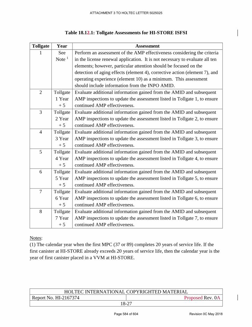
HOLTEC INTERNATIONAL COPYRIGHTED MATERIAL
Report No. HI-2167374 Proposed Rev. 0A
18-27
Table 18.12.1: Tollgate Assessments for HI-STORE ISFSI
Tollgate Year Assessment
1 See
Note 1
Perform an assessment of the AMP effectiveness considering the criteria
in the license renewal application. It is not necessary to evaluate all ten
elements; however, particular attention should be focused on the
detection of aging effects (element 4), corrective action (element 7), and
operating experience (element 10) as a minimum. This assessment
should include information from the INPO AMID.
2 Tollgate
1 Year
+ 5
Evaluate additional information gained from the AMID and subsequent
AMP inspections to update the assessment listed in Tollgate 1, to ensure
continued AMP effectiveness.
3 Tollgate
2 Year
+ 5
Evaluate additional information gained from the AMID and subsequent
AMP inspections to update the assessment listed in Tollgate 2, to ensure
continued AMP effectiveness.
4 Tollgate
3 Year
+ 5
Evaluate additional information gained from the AMID and subsequent
AMP inspections to update the assessment listed in Tollgate 3, to ensure
continued AMP effectiveness.
5 Tollgate
4 Year
+ 5
Evaluate additional information gained from the AMID and subsequent
AMP inspections to update the assessment listed in Tollgate 4, to ensure
continued AMP effectiveness.
6 Tollgate
5 Year
+ 5
Evaluate additional information gained from the AMID and subsequent
AMP inspections to update the assessment listed in Tollgate 5, to ensure
continued AMP effectiveness.
7 Tollgate
6 Year
+ 5
Evaluate additional information gained from the AMID and subsequent
AMP inspections to update the assessment listed in Tollgate 6, to ensure
continued AMP effectiveness.
8 Tollgate
7 Year
+ 5
Evaluate additional information gained from the AMID and subsequent
AMP inspections to update the assessment listed in Tollgate 7, to ensure
continued AMP effectiveness.
Notes:
(1) The calendar year when the first MPC (37 or 89) completes 20 years of service life. If the
first canister at HI-STORE already exceeds 20 years of service life, then the calendar year is the
year of first canister placed in a VVM at HI-STORE.
ATTACHMENT 3 TO HOLTEC LETTER 5025025
Page 584 of 604 Revision 0C May 2018
HOLTEC INTERNATIONAL COPYRIGHTED MATERIAL
Report No. HI-2167374 Proposed Rev. 0A
18-28
18.13 TIMING OF AGING MANAGEMENT IMPLEMENTATION
18.13.1 Canisters
Based on the fact that canisters will be arriving at the HI-STORE CIS that may have been stored
for extended period of time at other sites, it is important to identify when aging management will
be performed. Regardless of when aging management begins, the canisters will still be required to
undergo the acceptance testing described in Chapters 3 and 10.
Canister Age Less than 20 Years
If the canister arrives at HI-STORE at a date less than 20 years from the date of first being placed
on a storage pad, aging management is not required. Once the canister reaches 20 years from first
being placed on a storage pad, the aging management activities described in this chapter are
implemented. The canister is added to all other canisters undergoing aging management and the
selection criteria given in this chapter are utilized to determine which canisters need to be
inspected.
Canister Age Greater than 20 Years
If the canister arrives at HI-STORE at a date greater than 20 years from the date of first being
placed on a storage pad, the canister is added to the list of canisters undergoing aging management
immediately. The selection criteria given in this chapter are utilized to determine which canisters
need to be inspected.
18.13.2 All Other SSCs
For all other SSCs, which are constructed exclusively for the HI-STORE facility, the aging
management activities described in this chapter are implemented once the SSC reaches 20 years
from use for first loading. These may be separate dates for groups of HI-STORM UMAX VVMs,
as the construction of HI-STORE is designed to be performed in stages.
Chapter 10 of HI-STORE SAR discusses the operations and maintenance procedures established
for the equipment and lifting ancillaries used at HI-STORE CIS facility. The preoperational and
startup testing programs, and other tests and inspections of ISFSI equipment are located in Section
10.2.2, and the normal operations and maintenance procedures are located in Section 10.3 of
Chapter 10. Maintenance activities will be performed on brand new equipment and devices for 20
years prior to introduction of aging management, and it will be a combination of maintenance and
aging management from thereon.
As mentioned earlier, maintenance activities at the ISFSI will be carried out on dates of different
frequency. Overlapping of maintenance activity and aging management program may be expected
at a future date. Hence, if aging management is scheduled within 1 year of a maintenance program,
certain inspection activities may not need to be repeated, but the conditions of the SSC/device will
have to meet the acceptance criteria per AMP.
ATTACHMENT 3 TO HOLTEC LETTER 5025025
Page 585 of 604 Revision 0C May 2018
HOLTEC INTERNATIONAL COPYRIGHTED MATERIAL
Report No. HI-2167374 Proposed Rev. 0A
18-29
18.14 AMELIORATING THE RISK OF CANISTER DEGRADATION
OVER A LONG-TERM STORAGE DURATION
Industry data on SCC attack on austenitic stainless steels indicates that wet surfaces are more
vulnerable to attack than dry surfaces. Maintaining the proximate air’s relative humidity below
20%, as noted above, helps mitigate the risk of SCC. Noting that the canister’s internal heat
generation rate will decrease exponentially with the passage of time, its surface will get
progressively cooler. After a long period in storage, the canister’s surface may cool off sufficiently
to allow moisture to reside on it. From the SCC perspective, this is not a welcome situation. To
address this perverse effect of canister cool down, Holtec proposes to seek a license amendment
at a later date that will permit the inlet and/or outlet ventilation passages to be progressively
constricted so that the canister’s surface remains warm and moisture free.
This approach is a part of the long-term AMP (many decades from now) that Holtec International
expects to formalize and submit to the NRC for review.
ATTACHMENT 3 TO HOLTEC LETTER 5025025
Page 586 of 604 Revision 0C May 2018
HOLTEC INTERNATIONAL COPYRIGHTED MATERIAL
Report No. HI-2167374 Proposed Rev. 0A
18-30
18.15 RECOVERY PLAN
The AMP described in this chapter has been configured to provide an advance warning of the
potential of loss of Confinement integrity in a loaded canister. The accelerated coupon testing and,
if the coupon testing indicates onset of nucleation on the canister surface, then a comprehensive
canister wall integrity determination using eddy current testing provide a reliable strategy to
predict the risk of leakage well before such a problem would materialize.
Nevertheless, it is deemed prudent to have the ability to isolate an at-risk canister before leakage
occurs. Towards this end, Holtec will insure that a HI-STAR 190 transport cask can be brought to
the HI-STORE CIS site within 30 days after the site's Emergency Response organization identifies
such a need.
Finally, it should be noted that there is adequate cross sectional and vertical space available in the
VVM cavity to accommodate a highly conductive sequestration canister with a gasketed lid that
can be used to isolate a leaking canister from the environment. Such a sequestration canister can
be installed using the canister Transfer Facility using a set of steps that are ALARA. This
sequestration canister will provide a defense-in-depth measure (in addition to the transport cask
which provides a high integrity containment boundary) for dealing with an extenuating situation
involving the likelihood of an impending canister leak at the HI-STORE CIS site.
ATTACHMENT 3 TO HOLTEC LETTER 5025025
Page 587 of 604 Revision 0C May 2018
HOLTEC INTERNATIONAL COPYRIGHTED MATERIAL
Report No. HI-2167374 Proposed Rev. 0C
19-1
CHAPTER 19: CONSOLIDATED REFERENCES
References cited throughout this SAR are compiled in this chapter. Each reference may be cited multiple
times in multiple chapters. The context of the citation delineates the extent of reliance in this SAR on any
particular reference. No reference, unless so stated, is invoked in its entirety. Each reference is identified
by a decimal system (its native chapter. Section, and numeric sequence) and is enclosed in square brackets
throughout this document. All Holtec origin documents are proprietary subject to 10CFR2.390 protection
from dissemination except for Safety Analysis Reports which are available in redacted version in the Public
Document Room. The unabridged version of any referenced Holtec document is shared with the USNRC
upon request.
[1.0.1] Report to the Secretary of Energy, “Blue Ribbon Commission on America’s Nuclear
Future”, January 2012.
(https://energy.gov/sites/prod/files/2013/04/f0/brc_finalreport_jan2012.pdf)
[1.0.2] USNRC Regulatory Guide 3.50 “Standard Format and Content for a Specific License
Application for an Independent Spent Fuel Storage Installation or Monitored Retrievable
Storage Facility”, Revision 2, September 2014.
[1.0.3] USNRC NUREG-1567, “Standard Review Plan for Spent Fuel Dry Storage Facilities”,
March 2000.
[1.0.4] “Environmental Report on The HI-STORE CIS Facility”, Holtec Report 2167521, dated
March 2017
[1.0.5] 10 CFR Part 72, “Licensing Requirements for the Independent Storage of Spent Nuclear
Fuel, High-level Radioactive Waste, and Reactor-Related Greater than Class C Waste”,
Title 10 of the Code of Federal Regulations- Energy, Office of the Federal Register,
Washington, D.C.
[1.0.6] USNRC Docket 72-1040, “Final Safety Analysis Report on The HI-STORM UMAX
Canister Storage System”, Holtec Report No. HI-2115090, Revision 3. Submitted with
Holtec Letter 5021032 (ML16193A336), dated June 30, 3016
[1.2.1] “Aging Assessment and Management Program for HI-STORE CIS”, Holtec Report
2167378, Revision 0, dated March 2017
[1.2.2] NUREG/CR-6407, “Classification of Transportation Packaging and Dry Spent Fuel
Storage System Components According to Importance to Safety”, U.S. Nuclear
Regulatory Commission, February 1996.
[1.2.3] ANSI/NSF Standard 61, “Drinking Water System Components – Health Effects”, 2013.
[1.2.4] ANSI N14.6-1993, “American National Standard for Radioactive Materials - Special
Lifting Devices for Shipping Containers Weighing 10,000 Pounds (4,500 Kg) or More”,
American National Standards Institute, Inc., Washington D.C., June 1993.
ATTACHMENT 3 TO HOLTEC LETTER 5025025
Page 588 of 604 Revision 0C May 2018
HOLTEC INTERNATIONAL COPYRIGHTED MATERIAL
Report No. HI-2167374 Proposed Rev. 0C
19-2
[1.2.5] Interim Staff Guidance (ISG) – 2, “Fuel Retrievability”, Revision 1, February 22, 2010.
[1.2.6] Interim Staff Guidance (ISG) – 3, “Post Accident Recovery and Compliance with 10
CFR 72.122(l)”
[1.2.7] NUREG 0612, “Control of Heavy Loads at Nuclear Power Plants”, U.S. Nuclear
Regulatory Commission, Washington, D.C., July 1980.
[1.3.1] 10 CFR Part 50, “Domestic Licensing of Production and Utilization Facilities”, Title 10
of the Code of Federal Regulations, Office of the Federal Register, Washington, D.C.
[1.3.2] 10CFR Part 71, “Packaging and Transportation of Radioactive Material”, Title 10 of the
Code of Federal Regulations, Office of the Federal Register, Washington, D.C.
[1.3.3] USNRC Docket 72-1014, “Final Safety Analysis Report for the HI-STORM 100 Cask
System”, Holtec Report No. HI-2002444, Revision 14.
[1.3.4] USNRC Docket 72-1008, “Final Safety Analysis Report for the HI-STAR 100 Cask
System”, Holtec Report No. HI-2012610, Revision 3.
[1.3.5] USNRC Docket 71-9261, “Safety Analysis Report on the HI-STAR 100 Cask System”,
Holtec Report No. 951251, Revision 15.
[1.3.6] USNRC Docket 71-9373, “Safety Analysis Report on the HI-STAR 190 Package”,
Holtec Report No. 2146214, Revision 0.D.
[1.3.7] USNRC Docket 72-1032, “Final Safety Analysis Report on the HI-STORM FW
System”, Holtec Report No. HI-2114830, Revision 4.
[2.1.1] Eddy-Lea Energy Alliance. Memorandum of Agreement with Holtec International. April
2016.
[2.1.2] New Mexico Board of Finance. “Action Taken: Board of Finance Meeting.” Governor’s
Cabinet Room – Fourth Floor, State Capitol Building – Santa Fe, New Mexico. July 19,
2016.
[2.1.3] Eddy-Lea Energy Alliance. GNEP Siting Study. 2007.
(https://curie.ornl.gov/system/files/EDDY_LEA_Siting_Study_ML102440738.pdf)
[2.1.4] United States Department of Agriculture, Natural Resources Conservation Service
(USDA/NRCS). 2016. Soil Survey Geographic (SSURGO) Database for Lea County,
New Mexico. Soil Survey Staff, Natural Resources Conservation Service, United States
Department of Agriculture. Available at: http://websoilsurvey.sc.egov.usda.gov/
App/WebSoilSurvey.aspx , Accessed September 30, 2016.
[2.1.5] Dick-Peddie, W.A., W.H. Moir, and R. Spellberg. New Mexico Vegetation: Past, Present
and Future. Albuquerque, NM: University of New Mexico Press.
ATTACHMENT 3 TO HOLTEC LETTER 5025025
Page 589 of 604 Revision 0C May 2018
HOLTEC INTERNATIONAL COPYRIGHTED MATERIAL
Report No. HI-2167374 Proposed Rev. 0C
19-3
[2.1.6] Federal Emergency Management Agency (FEMA). Flood Insurance Study, Lea County,
New Mexico and Incorporated Areas. December 16, 2008.
[2.1.7] FEMA. FEMA Flood Map Service Center. Available at:
http://msc.fema.gov/portal/search?AddressQuery=Lea%20County%2C%20new%20me
xico#searchresultsanchor. Accessed October 2016.
[2.1.8] Holtec International. Data Call for the CISF Environmental Report. September 2016.
[2.1.9] U.S. Census Bureau (USCB). Table B01003, Total Population, American Community
Survey 5-Year Estimates. Available at:
http://factfinder.census.gov/bkmk/Table/1.0/en/ACS/11_5YR/B01003/0400000US35|0
400000US48|0500000US35015|0500000US35025|0500000US48003|0500000US48165
. Accessed on October 19, 2016.
[2.1.10] New Mexico Department of Workforce Solutions (NMDWS). New Mexico Annual
Social and Economic Indicator, Statistical Abstract for Data Users, 2015. Available at:
https://www.dws.state.nm.us/Portals/0/DM/LMI/ASEI_2015.pdf.
[2.1.11] Texas Demographic Center (Texas). Texas Population Projections. Available at:
http://txsdc.utsa.edu/data/TPEPP/Projections/Index. Accessed on October 19, 2016.
[2.1.12] U.S. Census Bureau (USCB). Table GCT-PH1, Population, Housing Units, Area, and
Density: 2010 – County, 2010 Census Summary File 1. Available at:
http://factfinder.census.gov/bkmk/Table/1.0/en/DEC/10_SF1/GCTPH1.CY07/0500000
US35015|0500000US35025|0500000US48003|0500000US48165.
[2.1.13] Environmental Justice Screen (EJSCREEN). EPA’s Environmental Justice Screening
and Mapping Tool (Version 2016). Location with 50-mile buffer. Available at:
https://ejscreen.epa.gov/mapper/. Accessed on October 14, 2016.
[2.1.14] CEHMM. “Transient Employment.” Email from Doug Lynn, Executive Director
CEHMM, to Tetra Tech on July 27, 2017.
[2.1.15] International Isotopes Fluorine Products, Inc. (IIFP). Fluorine Extraction Process &
Depleted Uranium De-conversion Plant (FEP/DUP) Environmental Report. December
27, 2009.
[2.1.16] AECOM. “Environmental Geology Assessment Report for Issues Related to the
Proposed Ochoa Mine, Lea County, New Mexico.” July 2012.
[2.1.17] CEHMM. “Oil and Gas Information.” E-mail from Doug Lynn, Executive Director
CEHMM, to Tetra Tech on July 31, 2017.
[2.1.18] Golder and Associates. Report to USDOI and USGS on Recommendations on
Abandonment of the Will-Weaver Mine and Shafts. Prepared for the U.S. Geological
Survey by Golder and Associates, November 1979.
ATTACHMENT 3 TO HOLTEC LETTER 5025025
Page 590 of 604 Revision 0C May 2018
HOLTEC INTERNATIONAL COPYRIGHTED MATERIAL
Report No. HI-2167374 Proposed Rev. 0C
19-4
[2.1.19] Intrepid Potash LLC. “Phone conversation with Mr. Robert Baldridge, Operations
Manager for Intrepid Potash, and Jay Rose, Tetra Tech.” July 25, 2017.
[2.1.20] New Mexico Bureau of Mines and Minerals Resources (NMBMMR). “Potash in New
Mexico.” February 1980.
[2.1.21] United Nations Environment Programme (UNEP). “Environmental Aspects of
Phosphate and Potash Mining. 2001.
[2.1.22] U.S. Geological Survey (USGS). “Geological Survey Circular 876-- Subsidence from
Underground Mining: Environmental Analysis and Planning Considerations.” 1983.
[2.1.23] CEHMM. “Holtec HI-Store Facility Area GIS Conflict Analysis.” October 7, 2016.
[2.1.24] GEI Consultants (GEI). “Geotechnical Data Report: HI-STORE CISF Phase 1 Site
Characterization.” February 2018.
[2.2.1] CEHMM. “Pipeline Information.” E-mail from Doug Lynn, Executive Director
CEHMM, to Tetra Tech on July 27, 2017.
[2.2.2] C-FER Technologies, Stephens, Mark. “A Model for Sizing High Consequence Areas
Associated with Natural Gas Pipelines.” October 2000.
[2.2.3] National Transportation Safety Board (NTSB). "Pipeline Accident Report PAR-03-01,
dated August 19, 2000." Available at: NTSB.gov. Accessed July 2017.
[2.2.4] Pipeline and Hazardous Materials Safety Administration (PHMSA). “Pipeline Safety.”
Available at: https://www.phmsa.dot.gov/. Accessed July 2017.
[2.2.5] Delta Airlines. Personal Communication between Captain Chick Winship, Delta Air
Lines and Jay Rose, Tetra Tech, on July 26, 2017.
[2.2.6] Military Training Routes (MTR). Available at:
http://www.cfinotebook.net/notebook/national-airspace-system/military-training-routes.
Accessed on July 26, 2017.
[2.2.7] National Hazardous Materials Route Registry (NHMRR). U.S. Department of
Transportation. Available at: www.fmcsa.dot./gov/regulations/hazardous-
materials/national-hazardous-materials-route-registry-state. Accessed on July 18, 2017.
[2.2.8] United States Department of Transportation (USDOT) Bureau of Transportation
Statistics. “State Transportation Statistics.” Available at: www.bts.gov. Accessed on July
18, 2017.
[2.2.9] New Mexico Department of Transportation (NMDOT). “Road Segments by Posted
Route/Point with (AADT) Info.” Email from Jessica Crane, NMDOT, to Tetra Tech.
November 30, 2016
ATTACHMENT 3 TO HOLTEC LETTER 5025025
Page 591 of 604 Revision 0C May 2018
HOLTEC INTERNATIONAL COPYRIGHTED MATERIAL
Report No. HI-2167374 Proposed Rev. 0C
19-5
[2.2.10] NMDOT. “New Mexico Freight Plan.” Available at:
dot.state.nm.us/content/dam/nmdot/planning/nm_2040_plan-freight_plan.pdf. August
2015.
[2.2.11] Department of Energy (DOE). Waste Isolation Pilot Plant Disposal Phase Final
Supplemental Environmental Impact Statement. DOE/EIS-0026-S2. September.
Available at: http://energy.gov/nepa/eis-0026-s2-waste-isolation-pilot-plant-disposal-
phase-carlsbad-new-mexico.
[2.2.12] DOE. Waste Isolation Pilot Plant Annual Site Environmental Report for 2014.
DOE/WIPP-15-8866. September 2015.
[2.2.13] NRC. Environmental Impact Statement for the Proposed National Enrichment Facility
in Lea County, New Mexico. NUREG-1790. June 2005.
[2.2.14] NRC. Environmental Impact Statement for the Proposed Fluorine Extraction Process
and Depleted Uranium Deconversion Plant in Lea County, New Mexico. NUREG-2113.
August 2012.
[2.2.15] Waste Control Specialists. “WCS Consolidated Interim Spent Fuel Storage Facility
Environmental Report.” May 2016. (Compiled from ADAMS Numbers: ML16133A137,
ML16133A161, ML16133A158, ML16133A139, ML16133A162, ML16133A153,
ML16133A151, ML16133A146, ML16133A145, ML16133A144, ML16133A143,
ML16133A142, ML16133A099)
[2.2.16] U.S. Department of Transportation Federal Aviation Administration, Albuquerque VFR
Sectional Chart, 101st Edition, 4/26/2018
[2.2.17] U.S. Department of Transportation Federal Aviation Administration, Order JO 7400.11B
“Airspace Designations and Reporting Points”, 8/3/2017
[2.2.18] U.S. Department of Transportation Federal Aviation Administration, Order 8260.19H
“Flight Procedures and Airspace”, 7/20/2017
[2.2.19] U.S. Department of Defense National Geospatial-Intelligence Agency, AP/1B “Flight
Information Publication: Area Planning: Military Training Routes: North and south
America”, 3/29/2018
[2.2.20] U.S. Department of Transportation Federal Aviation Administration, “Aeronautical
Information Services: Aeronautical Chart User’s Guide”, 3/29/2018
[2.2.21] 14 CFR Part 1.1, “Aeronautics and Space Definitions and Abbreviations”, Title 14 of the
Code of Federal Regulations – Transportation, Federal Aviation Administration,
Washington, D.C.
ATTACHMENT 3 TO HOLTEC LETTER 5025025
Page 592 of 604 Revision 0C May 2018
HOLTEC INTERNATIONAL COPYRIGHTED MATERIAL
Report No. HI-2167374 Proposed Rev. 0C
19-6
[2.2.22] U.S. Department of Transportation Federal Aviation Administration, FAA Form 5010-1
“FAA Airport Master Record for ATS” Available at:
http://www.gcr1.com/5010web/airport.cfm?Site=ATS&AptSecNum=2 , Accessed on
5/18/2018.
[2.2.23] U.S. Department of Transportation Federal Aviation Administration, FAA Form 5010-1
“FAA Airport Master Record for CNM” Available at:
http://www.gcr1.com/5010web/airport.cfm?Site=CNM&AptSecNum=2 , Accessed on
5/18/2018.
[2.2.24] U.S. Department of Transportation Federal Aviation Administration, FAA Form 5010-1
“FAA Airport Master Record for HOB” Available at:
http://www.gcr1.com/5010web/airport.cfm?Site=HOB&AptSecNum=2 , Accessed on
5/18/2018.
[2.2.25] U.S. Department of Transportation Federal Aviation Administration, FAA Form 5010-1
“FAA Airport Master Record for E06” Available at:
http://www.gcr1.com/5010web/airport.cfm?Site=E06&AptSecNum=2 , Accessed on
5/18/2018.
[2.2.26] U.S. Department of Transportation Federal Aviation Administration, FAA Form 5010-1
“FAA Airport Master Record for MAF” Available at:
http://www.gcr1.com/5010web/airport.cfm?Site=MAF&AptSecNum=2 , Accessed on
5/18/2018.
[2.2.27] U.S. Department of Transportation Federal Aviation Administration, FAA Form 5010-1
“FAA Airport Master Record for ROW” Available at:
http://www.gcr1.com/5010web/airport.cfm?Site=ROW&AptSecNum=2 , Accessed on
5/18/2018.
[2.2.28] U.S. Department of Transportation Federal Aviation Administration, Air Traffic Activity
Data System (ATADS)
[2.2.29] U.S. Department of Transportation Federal Aviation Administration, Order 8260.3D
“United States Standard for Terminal Instrument Procedures (TERPS)”, 2/16/2018
[2.2.30] Jeppesen, Instrument Approach Chart 12-3, CNM Cavern City Air Terminal, RNAV
(GPS) Runway 21
[2.2.31] Jeppesen, Instrument Approach Chart 11-1, HOB Lea County Regional Airport, ILS or
LOC Runway 3, 12/29/2017
[2.2.32] Email Correspondence from Dyess AFB Airspace Manager Dwight Williams, “RE:
[Non-DoD Source] Facility locations in Eddy and Lea Counties New Mexico.” to Beth
Bennington, Thursday, March 22, 2018
ATTACHMENT 3 TO HOLTEC LETTER 5025025
Page 593 of 604 Revision 0C May 2018
HOLTEC INTERNATIONAL COPYRIGHTED MATERIAL
Report No. HI-2167374 Proposed Rev. 0C
19-7
[2.2.33] NUREG 0800, “Standard Review Plan for the Review of Safety Analysis Reports for
Nuclear Power Plants”, U.S. Nuclear Regulatory Commission, Washington, D.C., March
2010
[2.3.1] Western Regional Climate Center Hobbs, Lea County Airport data. Available at:
http://www.wrcc.dri.edu/cgi-bin/cliMAIN.pl?nm4028. Accessed on October 14, 2016.
[2.3.2] Holzworth, G.C. Mixing Heights, Wind Speeds, and Potential for Urban Air Pollution
Throughout The Contiguous United States. January 1972.
[2.3.3] Greer. American Meteorological Society. Glossary of Weather and Climate. 1996.
[2.3.4] National Oceanic and Atmospheric Administration (NOAA). Enhanced F Scale for
Tornado Damage. Available at: http://www.spc.noaa.gov/faq/tornado/ef-scale.html.
Accessed on October 14, 2016.
[2.3.5] Tornado history. Available at: http://www.tornadohistoryproject.com/tornado/New-
Mexico/. October 14, 2016.
[2.4.1] Eddy-Lea Energy Alliance (ELEA). GNEP Siting Study. 2007.
[2.4.2] CEHMM. “Holtec Hi-Store Facility Area GIS Conflict Analysis.” October 7, 2016.
[2.4.3] Federal Emergency Management Agency (FEMA). FEMA Flood Map Service Center.
Available at: https://msc.fema.gov/portal.
[2.4.4] “Hydrologic Features.” 32.583, -103.708. Google Earth. February 1, 2017. Accessed
on: July 21, 2017.
[2.4.5] State of New Mexico Interstate Stream commission, Office of the State Engineer. Lea
County Regional Water Plan 1999. Available at:
http://www.ose.state.nm.us/Planning/RWP/region_16.php.
[2.4.6] State of New Mexico Interstate Stream commission, Office of the State Engineer. Lea
County Regional Water Plan 2016. Available at:
http://www.ose.state.nm.us/Planning/RWP/Regions/16_Lea%20County/2016/Reg%20
16_Lea%20County_Regional%20Water%20Plan%202016_December%202016.pdf
[2.4.7] NatureServe. International Ecological Classification Standard: Terrestrial Ecological
Classifications. NatureServe Central Databases. Arlington, VA. U.S.A. 2009.
[2.4.8] NatureServe. Madrean Archipelago Rapid Ecoregional Assessment Pre-Assessment
Report. Arlington, Virginia. 2013.
[2.4.9] USGS. 3D Elevation Program (Resolution 1/3 arc second (10 meters)). Available at:
https://nationalmap.gov
ATTACHMENT 3 TO HOLTEC LETTER 5025025
Page 594 of 604 Revision 0C May 2018
HOLTEC INTERNATIONAL COPYRIGHTED MATERIAL
Report No. HI-2167374 Proposed Rev. 0C
19-8
[2.4.10] RGIS. New Mexico Resource Geographic Information System. Available at:
http://rgis.unm.edu/
[2.4.11] USDA. NRCS Web Soil Survey. Available at:
https://websoilsurvey.sc.egov.usda.gov/App/WebSoilSurvey.aspx
[2.4.12] U.S. Fish and Wildlife Service. National Wetlands Inventory, Wetlands-Data. Available
at: https://www.fws.gov/wetlands/data/Google-Earth.html.
[2.4.13] NOAA. NOAA Atlas 14 Point Precipitation Frequency Estimates: NM. Available at:
https://hdsc.nws.noaa.gov/hdsc/pfds/pfds_map_cont.html
[2.4.14] Bonnin, M., D. Martin, B. Lin, T. Parzybok, M. Yekta, and D. Riley, “Precipitation
Frequency Atlas of the United States: NOAA Atlas 14, Volume 1: Semiarid Southwest
(Arizona, Southeast California, Nevada, New Mexico, Utah),” Version 5.0, Silver
Spring, MD: U.S. Department of Commerce, National Oceanic and Atmospheric
Administration, National Weather Service, 2011.
[2.5.1] New Mexico Office of the State Engineer (NMOSE). Declared Underground Water
Basins Map. Available at: http://www.ose.state.nm.us/GIS/maps.php. Accessed October
2016.
[2.5.2] Nicholson, Alexander Jr. and Alfred Clebsch, Jr. 1963. Ground-water Report 6, Geology
and Ground-water Condition in Southern Lea County, New Mexico. State Bureau of
Mines and Mineral Resources, New Mexico Institute of Mining and Technology. 1963.
[2.6.1] Powers, D. W., Lambert, S. J., Shaffer, S. E., Hill, L. R., and Weart, W. D., eds., 1978,
Geological Characterization Report for the Waste Isolation Pilot Plant (WIPP) Site,
Southeastern New Mexico. SAND78-1596, Vols. I and II. Sandia National Laboratories.
[2.6.2] Nuclear Regulatory Commission (NRC). Safety Evaluation Report for the National
Enrichment Facility in Lea County, New Mexico, Louisiana Energy Services (NUREG-
1827), Available at: http://www.nrc.gov/reading-rm/doc-
collections/nuregs/staff/sr1827/, Accessed October 28, 2016.
[2.6.3] United States Geological Survey (USGS). Earthquake Archive Search. Available at:
http://earthquake.usgs.gov/earthquakes/search/. Accessed on September 29, 2016.
[2.6.4] USGS. Earthquake Probability Mapping, 2009 PSHA Model. United States Geological
Survey. Available at: http://geohazards.usgs.gov/eqprob/2009/. Accessed on October 13,
2016.
[2.6.5] Sanford A., Balch, R., and Delap S., 1993, Report 68: A Review of the Seismicity and
Seismic Risk at the WIPP Site, Geoscience Department and Geophysical Research
Center, New Mexico Tech. Available at: https://www.ees.nmt.edu/
images/ees/Geop/nmquakes/R68/R68.HTM Accessed October 24, 2016.
ATTACHMENT 3 TO HOLTEC LETTER 5025025
Page 595 of 604 Revision 0C May 2018
HOLTEC INTERNATIONAL COPYRIGHTED MATERIAL
Report No. HI-2167374 Proposed Rev. 0C
19-9
[2.6.6] Safety Evaluation Report for Approval of DOE/WIPP 07-3372, Waste Isolation Pilot
Plant Documented Safety Analysis, Revision 5 and DOE/WIPP 07-3373, Waste Isolation
Pilot Plant Technical Safety Requirements, Revision 5
[2.6.7] USGS. Quaternary Faults in Google Earth. Available at: http://earthquake.usgs.gov
/hazards/qfaults/google.php . Accessed on September 29, 2016.
[2.6.8] USGS. Geologic Hazards Map. Available at: http://geohazards.usgs.gov/hazards/
apps/cmaps/ . Accessed September on 30, 2016.
[2.6.9] Mineral Lease Relinquishment Agreement between Intrepid Potash and Holtec
International, October 5, 2016.
[2.6.10] 10 CFR Part 100, “Reactor Site Criteria”, Title 10 of the Code of Federal Regulations,
Office of the Federal Register, Washington, D.C.
[2.6.11] USNRC Regulatory Code 1.198, “Procedures and Criteria for Assessing Seismic
Liquefaction at Nuclear Power Sites”, November 2003.
[2.6.12] Youd, T.L., et al. “Liquefaction Resistance of Soils: Summary Report from the 1996
NCEER and 1998 NCEER/NSF Workshops on Evaluation of Liquefaction Resistance of
Soils.” American Society of Civil Engineers, Journal of Geotechnical and
Geoenvironmental Engineering, October 2001.
[2.7.1] Regulatory Guide 1.76, “Design Basis Tornado and Tornado Missiles for Nuclear Power
Plants,” United States Nuclear Regulatory Commission, March 2007.
[2.7.2] ANSI/ANS 57.9-1992, "Design Criteria for an Independent Spent Fuel Storage
Installation (Dry Type)", American Nuclear Society, LaGrange Park, IL, May 1992.
[3.0.1] ASME NOG-1, Rules for Construction of Overhead and Gantry Cranes (Top Running
Bridge, Multiple Girder), American Society of Mechanical Engineers, New York, 2015.
[3.1.1] Holtec International & Eddy Lea Energy Alliance (ELEA) Underground Consolidated
Interim Storage Facility – Physical Security Plan, Holtec Report HI-2177559, Latest
Revision.
[3.1.2] 49 CFR 171, “General Information, Regulations, and Definitions,” Title 49 of the Code
of Federal Regulations – Transportation, Office of the Federal Register, Washington,
D.C.
[3.1.3] 49 CFR 172, “Hazardous Materials Table, Special Provisions, Hazardous Materials
Communications, Emergency Response Information, Training Requirements, and
Security Plans,” Title 49 of the Code of Federal Regulations – Transportation, Office of
the Federal Register, Washington, D.C.
[3.1.4] 49 CFR 174, “Carriage by Rail,” Title 49 of the Code of Federal Regulations –
Transportation, Office of the Federal Register, Washington, D.C.
ATTACHMENT 3 TO HOLTEC LETTER 5025025
Page 596 of 604 Revision 0C May 2018
HOLTEC INTERNATIONAL COPYRIGHTED MATERIAL
Report No. HI-2167374 Proposed Rev. 0C
19-10
[3.1.5] 49 CFR 177, “Carriage by Public Highway,” Title 49 of the Code of Federal Regulations
– Transportation, Office of the Federal Register, Washington, D.C.
[4.0.1] ISG-11, “Cladding Considerations for the Transport and Storage of Spent Fuel,”
USNRC, Washington, DC, Revision 3, November 17, 2003.
[4.2.1] Holtec Position Paper DS-381, “Guidelines for Specifying ITS Categories,” Revision 0,
dated October 8, 2012
[4.2.2] Holtec Standard Procedure HSP 345, Important-to-Safety Classification Procedure.
[4.3.1] ASLB Hearings, Private Fuel Storage, LLC, Docket # 72-22-ISFSI, ASLBP 97-732-02-
ISFSI, February 2005.
[4.3.2] U.S. Nuclear Regulatory Commission, Regulatory Guide 1.60, “Design Response
Spectra for Seismic Design of Nuclear Power Plants,” Revision 1, 1973.
[4.3.3] U.S. Nuclear Regulatory Commission, Regulatory Guide 1.92, “Combining Modal
Responses and Spatial Components in Seismic Response Analysis,” Revision 2, 2006.
[4.3.4] ASCE 4-16, “Seismic Analysis of Safety-Related Nuclear Structures,” American Society
of Civil Engineers, 2017.
[4.3.5] “HI-STORE Bearing Capacity and Settlement Calculations”, Holtec Report HI-2188143,
Revision 0.
[4.5.1] ASME Boiler and Pressure Vessel Code, Section III, Division 1, Subsection NF -
Supports, 2010.
[4.5.2] Crane Manufacturer's Association of America (CMAA), Specification #70, 1988,
Section 3.3.
[4.5.3] ASME Boiler and Pressure Vessel Code, Welding, Section IX, 2010.
[4.5.4] AWS D1.1:2006 Structural Welding Code – Steel, 2008.
[4.5.5] ISO 9001:2008, Quality Management Systems.
[4.5.6] American Society of Mechanical Engineers, American National Standard, Safety
Standards, “Slings”, ASME B30.9, 1971
[4.5.7] National Fire Protection Association (NFPA), NFPA 70, “National Electric Code”.
[4.5.8] American Society of Mechanical Engineers, American National Standard, Safety
Standards, “Jacks”, ASME B30.1-2009.
ATTACHMENT 3 TO HOLTEC LETTER 5025025
Page 597 of 604 Revision 0C May 2018
HOLTEC INTERNATIONAL COPYRIGHTED MATERIAL
Report No. HI-2167374 Proposed Rev. 0C
19-11
[4.5.9] American Institute for Steel Construction (AISC), Specification for Structural Steel
Buildings, Allowable Stress Design and Plastic Design, 13th Edition.
[4.5.10] ASTM D92, “Standard Test Method for Flash and Fire Points”.
[4.5.11] American National Standard Institute, “Overhead and Gantry Cranes (Top Running
Bridge, Single or Multiple Girder, Top Running Trolley Hoist)”, ANSI B30.2, 1976.
[4.5.12] National Fire Protection Association NFPA 10-2013 Standard for Portable Fire
Extinguishers.
[4.6.1] ANSI/ASCE 7-05 (formerly ANSI A58.1), “Minimum Design Loads for Buildings and
Other Structures,” American Society of Civil Engineers, 2006.
[4.6.2] ASCE 7-10, “Minimum Design Loads for Building and Other Structures,” American
Society of Civil Engineers, 2013.
[4.6.3] ASME Boiler and Pressure Vessel Code, Section II, Part D, Properties, 2010.
[4.6.4] International Building Code (IBC), International Code Council, 2015.
[5.3.1] ACI-318 (2005), Building Code Requirements for Structural Concrete (ACI 318-05) and
Commentary (ACI 318R-05), American Concrete Institute, 2005.
[5.3.2] Boresi, A. et al., Advanced Mechanics of Materials, John Wiley and Sons, Third Edition.
[5.4.1] U.S. Nuclear Regulatory Commission, “Standard Review Plan Chapter 3.7.1 – Seismic
Design Parameters”, Revision 3, March 2007.
[5.4.2] LS-DYNA, Version 971, Livermore Software Technology, 2012.
[5.4.3] ASME BTH-1-2011, Design of Below-the-Hook Lifting Devices, January 2012.
[5.4.4] “Regulatory Guide 1.60 Time Histories Using EZ-FRISK”, Holtec Report HI-2146083,
Revision 2.
[5.4.5] ASCE/SEI 43-05, Seismic Design Criteria for Structures, Systems, and Components in
Nuclear Facilities, American Society of Civil Engineers, 2005.
[5.4.6] “Structural Calculation Package for HI-STORE CIS Facility”, Holtec Report HI-
2177585, Revision 0.
[5.4.7] “Structural Calculation Package for the HI-STORM UMAX System”, Holtec Report HI-
2125228, Revision 9.
[5.5.1] ANSYS (Versions up to 17.1), SAS IP, Inc., 2016.
ATTACHMENT 3 TO HOLTEC LETTER 5025025
Page 598 of 604 Revision 0C May 2018
HOLTEC INTERNATIONAL COPYRIGHTED MATERIAL
Report No. HI-2167374 Proposed Rev. 0C
19-12
[6.4.1] FLUENT Computational Fluid Dynamics Software, Fluent, Inc., Centerra Resource
Park, 10 Cavendish Court, Lebanon, NH 03766.
[6.4.2] “Topical Report on the HI-STAR/HI-STORM Thermal Model and its Benchmarking
with Full-Size Cask Test Data,” Holtec Report HI-992252, Revision 1, Holtec
International, Marlton, NJ, 08053.
[6.4.3] “Standard for Verification and Validation in Computational Fluid Dynamics and Heat
Transfer”, ASME V&V 20-2009.
[6.4.4] “Procedure for Estimating and Reporting of Uncertainty due to Discretization in CFD
Applications”, I.B. Celik, U. Ghia, P.J. Roache and C.J. Freitas (Journal of Fluids
Engineering Editorial Policy on the Control of Numerical Accuracy).
[6.4.5] Perry, Robert.H., Perry’s Chemical Engineers’ Handbook, Sixth Edition, Texas:
McGraw-Hill, pg. 3-167, 1984.
[6.4.6] “Fuel, Weather and Considerations”, United States Department of Agriculture, Forest
Service Southern Region, February 1989; Technical Publication R8-TP 11.
[6.5.1] Gregory, J.J. et. al., “Thermal Measurements in a Series of Large Pool Fires”, SAND85-
1096, Sandia National Laboratories, (August 1987).
[6.5.2] Jakob, M. and Hawkins, G.A., “Elements of Heat Transfer,” John Wiley & Sons, New
York, (1957).
[6.5.3] “Evaluation of Effects of Tracked VCT Fire on HI-STORM FW System”, Holtec Report
HI-2135677, Latest Revision.
[6.5.4] “Thermal Analysis of HI-TRAC CS Transfer Cask”, Holtec Report HI-2177553,
Revision 0.
[6A.1] Darr, J.H., and S.P. Vanka, "Separated flow in a driven trapezoidal cavity", Physics
Fluids A, 3, 3, 385-392, (March 1991).
[6A.2] Young, D.F. and F.Y. Tsai, "Flow characteristics in models of arterial stenoses-I steady
flow", Journal of Biomechanics, 6, 395-410, (1973).
[6A.3] Coutanceau, M. and J.R. Defaye, "Circular cylinder wake configurations - A flow
visualization survey", Applied Mechanics Review, 44, 6, (June 1991).
[6A.4] Braza, M.P. Chassaing and H.H. Minh, "Numerical study and physical analysis of the
pressure and velocity fields in the near wake of a circular cylinder", Journal of Fluid
Mechanics, 165, 79-130, (1986).
[6A.5] Hayes, R.E., K. Nandkumar and H. Nasr-El-Din, "Steady laminar flow in a 90 degree
planar branch", Computers and Fluids, 17, 4, 537-553, (1989).
ATTACHMENT 3 TO HOLTEC LETTER 5025025
Page 599 of 604 Revision 0C May 2018
HOLTEC INTERNATIONAL COPYRIGHTED MATERIAL
Report No. HI-2167374 Proposed Rev. 0C
19-13
[6A.6] Kuehn, T.H. and R.J. Goldstein, "An experimental study of natural convection heat
transfer in concentric and eccentric horizontal cylinder annuli", Journal of Heat Transfer,
100, 635-640, (1978).
[6A.7] Yucel, A., S. Acharya and M.L. Williams, "Natural convection and radiation in a square
enclosure", Numerical Heat Transfer, Part A, 15, 261-278, (1989).
[6A.8] Sorensen, J.N. and T.P. Loc, "Higher-order axisymmetric Navier-Stokes Code:
Description and evolution of boundary conditions", International Journal for Numerical
Methods in Fluids, 9, 1517-1537, (1989).
[6A.9] Michelsen, J.A., “Modelling of laminar incompressible rotating fluid flow”, AFM 86-05,
Ph.D. dissertation, Department of fluid mechanics, Technical University of Denmark,
(1986).
[6A.10] Eidelman, S., P. Collela and R.P. Shreeve, “Application of the Godunov method and its
second-order extension to cascade flow modelling”, AIAA Journal, 22, 1609-1615,
(1984).
[6A.11] Karki, K.C., “A calculational procedure for viscous flows at all speeds in complex
geometries”, Ph.D. Thesis, U. of Minnesota, (1986).
[6A.12] Vogel, J.C. and J.K. Eaton, “Combined heat transfer and fluid dynamic measurements
downstream of a backward facing step”, Journal of Heat Transfer, 107, 922-929, (1985).
[6A.13] Antonopoulos, K.A., “The prediction of turbulent inclined flow in rod bundles”,
Computers and Fluids, 14, 4, 361-378, (1986).
[6A.14] Humphrey, T.A.C., A.M.K. Taylor and J.H. Whitelaw, “Laminar flow in a square duct
of strong curvature”, Journal of Fluid Mechanics, 83, 509-527, (1977).
[6A.15] Rogers, S.E., D. Kwak and C. Kiris, “Steady and Unsteady Solutions of the
Incompressible Navier-Stokes Equations”, AIAA Journal, 29, 4, 603-610, (April 1991).
[6A.16] Yeo, R.N., P.E. Wood and A.N. Hrymak, “A numerical study of laminar 90-degree bend
duct flow with different discretization schemes”, Journal of Fluid Engineering, 113, 563-
568, (December 1991).
[6A.17] Bradley, D., L.A. Kwa, A.K.C. Lau, M. Missaghi and S.B. Chin, “Laminar Flamelet
modelling of recirculating premixed methane and propane-air combustion”, Combustion
and Flame, 71, 109-122, (1988).
[6A.18] Kakac, S., R.K. Shah and W. Aung, “Handbook of single-phase convective heat
transfer”, Wiley interscience, NY, (1987).
[6A.19] Stanitz, J.D., W.M. Osborn and Mizisin, “An experimental investigation of secondary
flow in an accelerating rectangular elbow with 90 degree turning”, NACA-TN-30150,
(1953).
ATTACHMENT 3 TO HOLTEC LETTER 5025025
Page 600 of 604 Revision 0C May 2018
HOLTEC INTERNATIONAL COPYRIGHTED MATERIAL
Report No. HI-2167374 Proposed Rev. 0C
19-14
[6A.20] EPRI, "The TN-24P PWR Spent Fuel Storage Cask: Testing and Analyses, EPRI ND-
5128, April 1987.
[6A.21] “Topical Report on the HI-STAR/HI-STORM Thermal Model and its Benchmarking
with Full-Size Cask Test Data”, Holtec Report HI-992252, Revision 1.
[7.0.1] Safety Evaluation Report for the HI-STORM UMAX System, Amendment 0, dated April
2, 2015, ML15093A510.
[7.0.2] Safety Evaluation Report for the HI-STORM UMAX System, Amendment 1, dated
September 8, 2015, ML15252A423.
[7.0.3] Safety Evaluation Report for the HI-STORM UMAX System, Amendment 2, dated
January 6, 2017, ML16341B129.
[7.4.1] 10 CFR Part 20 “Standards for Protection Against Radiation,” Title 10, of the Code of
Federal Regulations – Energy, Office of the Federal Register, Washington, D.C.
[8.0.1] Safety Evaluation Report for the HI-STORM FW System, Amendment 0, dated July 14,
2011, ML111950325.
[8.0.2] Safety Evaluation Report for the HI-STORM FW System, Amendment 1, dated
December 17, 2014, ML14351A475.
[8.0.3] Safety Evaluation Report for the HI-STORM FW System, Amendment 2, dated October
25, 2016, ML16280A302.
[10.1.1] HI-STORE CISF Specialist Training Program.
[10.1.2] ANSI N18.1. “Selection and Training of Nuclear Power Plant Personnel”, American
National Standards Institute, Inc., Washington D.C., 1971.
[10.1.3] HI-STORE CISF Radiation Protection Technician Training Program.
[10.3.1] 49 CFR 173, “Shippers – General Requirements for Shipments and Packagings,” Title
49 of the Code of Federal Regulations – Transportation, Office of the Federal Register,
Washington, D.C.
[10.3.2] American Society for Nondestructive Testing, “Personnel Qualification and Certification
in Nondestructive Testing,” Recommended Practice No. SNT-TC-1A, December 1992.
[10.3.3] ANSI N14.5, American National Standard for Radioactive Materials – Leakage Tests on
Packages for Shipment, 2014.
[10.5.1] Holtec CISF Emergency Response Plan, Holtec Report HI-2177535, dated March 2017.
[11.1.1] U.S. Code of Federal Regulations, Title 10, “Energy” Part 19 “Notices, Instructions and
Reports to Workers: Inspection and Investigations”.
ATTACHMENT 3 TO HOLTEC LETTER 5025025
Page 601 of 604 Revision 0C May 2018
HOLTEC INTERNATIONAL COPYRIGHTED MATERIAL
Report No. HI-2167374 Proposed Rev. 0C
19-15
[11.1.2] U.S. Nuclear Regulatory Commission “Information Relevant to Ensuring that
Occupational Radiation Exposures at Nuclear Power at Nuclear Power Stations will be
As Low As Reasonably Achievable”, Regulatory Guide 8.8, June 1978.
[11.1.3] U.S. Nuclear Regulatory Commission, "Operating Philosophy for Maintaining
Occupational and Public Radiation Exposures As Low As is Reasonably Achievable",
Regulatory Guide 8.10, Revision 2, August 2016.
[11.4.1] U.S. Nuclear Regulatory Commission “Personnel Monitoring Device – Direct-Reading
Pocket Dosimeters” Regulatory Guide 8.4, Revision 1. June 2011.
[11.4.2] NUREG/CR-0041, “Manual of Respiratory Protection Against Airborne Radioactive
Material” U.S. Nuclear Regulatory Commission, Revision 1. January 2001.
[12.0.1] Holtec International Quality Assurance Program, Latest Approved Revision on Docket
71-0784.
[13.3.1] Holtec Report HI-2177558, “Holtec International & Eddy Lea Energy Alliance (ELEA)
Underground Consolidated Interim Storage Facility - Decommissioning Plan,” dated
March 2017
[13.3.2] Holtec Report HI-2177565, “Holtec International & Eddy Lea Energy Alliance (ELEA)
CIS Facility - Decommissioning Cost Estimate and Funding Plan”.
[13.3.3] NUREG-1757 Volume 1, “Consolidated Decommissioning Guidance”.
[13.3.4] NUREG-1757 Volume 3, “Consolidated Decommissioning Guidance, Financial
Assurance, Recordkeeping and Timeliness”.
[13.3.5] R.S. Means, Construction Cost Data, 2017.
[15.3.1] NUREG-1536, “Standard Review Plan for Spent Fuel Dry Storage Systems at a General
License Facility”, Rev 1, U.S. Nuclear Regulatory Commission, Washington, DC.
[16.0.1] HI-STORM UMAX CoC, Amendments 0, 1, 2, Issued April 6, 2015, September 8, 2015
and January 9, 2017 respectively.
[16.0.2] Proposed HI-STORE CIS Facility License SNM-1051, Appendix A (Technical
Specifications), Revision 0, March 31, 2017.
[17.0.1] ISG-15, “Materials Evaluation,” USNRC, Washington D.C., dated January 10, 2001
[17.2.1] Morgan Thermal Ceramics Inc., Product Data Sheet for Blanket Products (Kaowool®
Blanket).
[17.2.2] “Properties, Behavior and Construction Use of Controlled Low Strength Material
(CLSM) (U),” Engineering Studies Research Report K-ESG-G-00004, Revision 1.0,
September 2002, Geotechnical Engineering Group.
ATTACHMENT 3 TO HOLTEC LETTER 5025025
Page 602 of 604 Revision 0C May 2018
HOLTEC INTERNATIONAL COPYRIGHTED MATERIAL
Report No. HI-2167374 Proposed Rev. 0C
19-16
[17.2.3] “Guide Specification for Controlled Low Strength Materials (CLSM)”, National Ready
Mixed Concrete Association, Silver Spring, MD.
[17.3.1] ASME Boiler and Pressure Vessel Code, Section II, Part A – Ferrous Material
Specifications,” American Society of Mechanical Engineers, New York, NY, 2010
Edition.
[17.3.2] ASME Boiler and Pressure Vessel Code, Section III, Appendices, 2010 Edition.
[17.7.1] Reg. Guide 1.54, “Service Level I, II, and III Protective Coatings Applied to Nuclear
Power Plants”, Revision 2, US Nuclear Regulatory Commission, Washington, DC.
[17.7.2] ASTM D 3843-00, “Standard Practice for Quality Assurance for Protective Coatings
Applied to Nuclear Facilities”, ASTM International, West Conshohocken, PA.
[17.7.3] ANSI C 210-03, “Liquid Epoxy Coating Systems for the Interior and Exterior of Steel
Water Pipes”.
[17.7.4] ASTM D4082-10, “Standard Test Method for Effects of Gamma Radiation on Coatings
for use in Nuclear Power Plants”, ASTM International, West Conshohocken, PA.
[17.10.1] Rogers Corporation, Product Data Sheet for BISCO® Silicones (BF-1000 – Extra Soft
Cellular Silicone).
[17.11.1] SECY-14-0072, “Final Rule: Continued Storage of Spent Nuclear Fuel,” dated July 14,
2014, as supported by NUREG-2157, “Generic Environmental Impact Statement for
Continued Storage of Spent Nuclear Fuel”.
[18.0.1] NUREG-1927, “Standard Review Plan for Renewal of Specific Licenses and Certificates
of Compliance for Dry Storage of Spent Nuclear Fuel” Revision 1 – USNRC 2016
ADAMS # ML16179A148.
[18.0.2] NEI 14-03, “Format, Content and Implementation Guidance for Dry Cask Storage
Operations-Based Aging Management for Dry Cask Storage” Revision 1 – NEI 2015
ADAMS # ML15272A329.
[18.3.1] USNRC Docket 72-1014, “Final Safety Analysis Report on the HI-STORM 100 Cask
System”, Holtec Report No. HI-2002444, Revision 1.
[18.4.1] “MPC Surface Inspection of Diablo Canyon Power Plant”, Holtec Report No. HI-
2146301, Revision 2.
[18.5.1] “Susceptibility Assessment Criteria for Chloride-Induced Stress Corrosion Cracking
(CISCC) of Welded Stainless Steel Canisters for Dry Cask Storage Systems”, EPRI
Report No. 3002005371, 2015.
[18.5.2] ASTM G 30, “Standard Practice for Making and Using U-Bend Stress Corrosion Test
Specimens”, ASTM ,100 Barr Harbor Drive, W Conshohocken, PA 19428-2959, 1997.
ATTACHMENT 3 TO HOLTEC LETTER 5025025
Page 603 of 604 Revision 0C May 2018
HOLTEC INTERNATIONAL COPYRIGHTED MATERIAL
Report No. HI-2167374 Proposed Rev. 0C
19-17
[18.5.3] ASTM G 1, “Standard Practice for Preparing, Cleaning, and Evaluating Corrosion Test
Specimens”, ASTM 100 Barr Harbor Drive, W Conshohocken, PA 19428, 2011.
[18.5.4] ASME Section V, “Nondestructive Examination”, Two Park Avenue, New York, NY
10016, 2015.
ATTACHMENT 3 TO HOLTEC LETTER 5025025
Page 604 of 604 Revision 0C May 2018
Related Documents


![Role of planting depth and mulching on growth and yield ... · Ilyas & Ayub 1437 exceed17 0C [3] and the optimal temperature for tuber bulking ranges between 14 0C and 22 0C. Higher](https://static.cupdf.com/doc/110x72/5b91fe9509d3f210288cefcd/role-of-planting-depth-and-mulching-on-growth-and-yield-ilyas-ayub-1437.jpg)