HF- radar for coastal erosion application Dr.Wattana Kanbua Director of Marine Meteorological Center Friday March 27 2009

Welcome message from author
This document is posted to help you gain knowledge. Please leave a comment to let me know what you think about it! Share it to your friends and learn new things together.
Transcript
HF- radar for
coastal erosion application
Dr.Wattana Kanbua
Director of Marine Meteorological Center
Friday March 27 2009
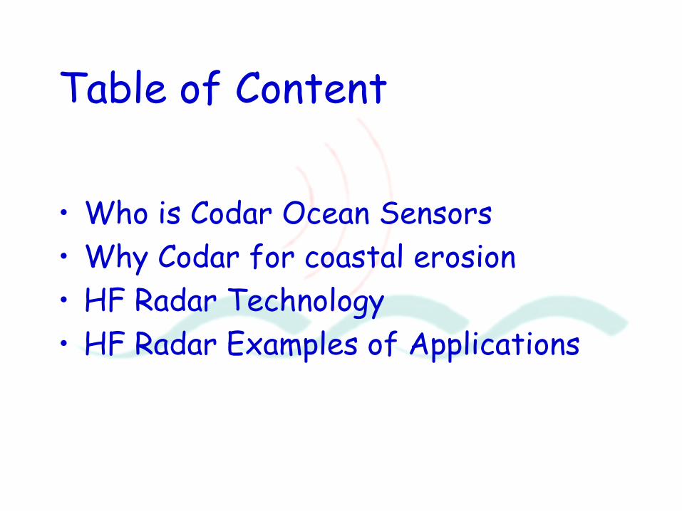
Table of Content
• Who is Codar Ocean Sensors
• Why Codar for coastal erosion
• HF Radar Technology
• HF Radar Examples of Applications
CODAR Ocean Sensors, Ltd. The Leader in HF Surface-Wave Radar Ocean Monitoring • Company principals have been continuously involved in HFSWR for 40 years
– Patented CODAR Hallmarks:
• Compact antenna system --small footprint offers unobtrusive coastal presence
• Unmanned, real-time operation
• Low power -- both radiated and required input supply
• GPS-synchronized multiple-radar and multi-static operation at same frequency
• Currents mapped to 200 km with Long-Range backscatter SeaSondes
• Bistatic augmentation by CODAR demonstrates coverage extension to 330 km
• Over 300 CODAR SeaSondes manufactured and sold -- 85% of all HFSWRs – Systems logged over 5 million operating hours to date
• Recent "Dual-Use" objectives being pursued to examine ship detection/tracking – Robust, multiple-look at same target defies evasion
• HFSWR is CODAR's only product -- provides us unparalleled focus of direction
• Local waveheights and direction

To be able to understand coastal erosion and design effective
wave breakers oceanographic data such as:
Wave height
Waveperiod
Wave direction
Current speed
Current direction
are needed.
HF- radar is an ideal instrument to measure all these parameters
over a large area without having any instruments in the water
HF-radar is the only instrument measuring all the
parameters over a large area without anything in the water
Why HF radar for coastal erosion?
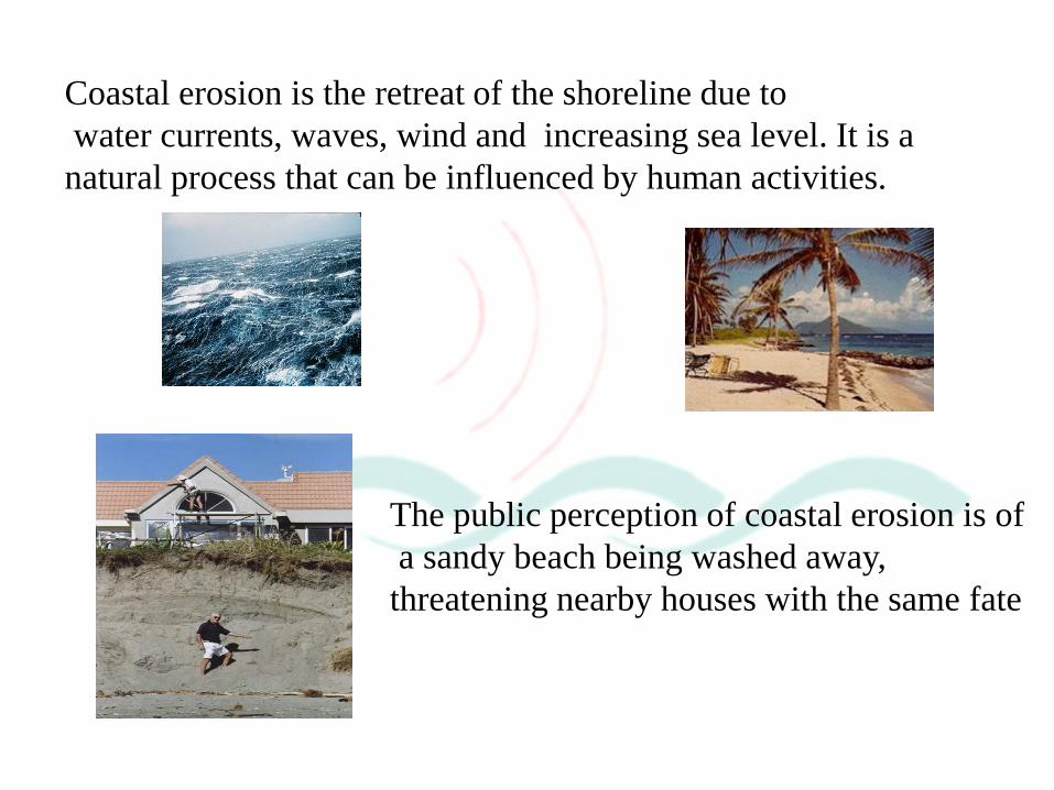
Coastal erosion is the retreat of the shoreline due to
water currents, waves, wind and increasing sea level. It is a
natural process that can be influenced by human activities.
The public perception of coastal erosion is of
a sandy beach being washed away,
threatening nearby houses with the same fate
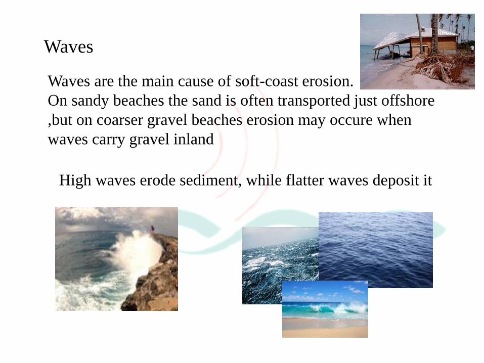
Waves
Waves are the main cause of soft-coast erosion.
On sandy beaches the sand is often transported just offshore
,but on coarser gravel beaches erosion may occure when
waves carry gravel inland
High waves erode sediment, while flatter waves deposit it

Similar to how a police radar measures
car speed, HF radars measure ocean
surface current speed by precisely
measuring the Doppler shifts produced
by the radar signal bouncing off the
moving object.
Realize, radar can only measure
the movement directly towards or
away from the radar.
How HF Radar Works -- Doppler!

Why Use HF?
• HF => High Frequency (radio spectrum between 4 - 50 MHz, l between 6 - 75 m).
• Signals travel well beyond the horizon, much farther than microwave signals that are limited to line-of-sight (Ham radio operators use HF for same reason).
• Only HF signals respond to ocean waves in a very predictable manner, hence allowing us to derive ocean surface current, wave, and hard target information
• Advantages of CODAR SeaSonde HF Radars:
• Operate from shore, without any instrumentation in water!
• Provide wide area surveillance, up to 340 km from shore
• Automated operation, with continuous coverage
• Very little maintenance required, low operating costs
• What Is Observed or Measured?
• The SeaSonde HF radar detects surface currents movement in speed and direction , and tsunami-induced current signature
• It also provides local wave conditions

Each SeaSonde® HF Radar station consists of the components (shown
at left).
The antennas are placed at the coast, connected via cables to
electronics that operate within an environmentally controlled shelter
(as shown on right).
An additional computer located at your office allows for remote
modem access to and control of radars, as well as automatic data
retrieval.
Computer and Monitor Transmitter
Receiver
Transmit
Antenna
Receive
Antenna
What Does a SeaSonde® Look Like?
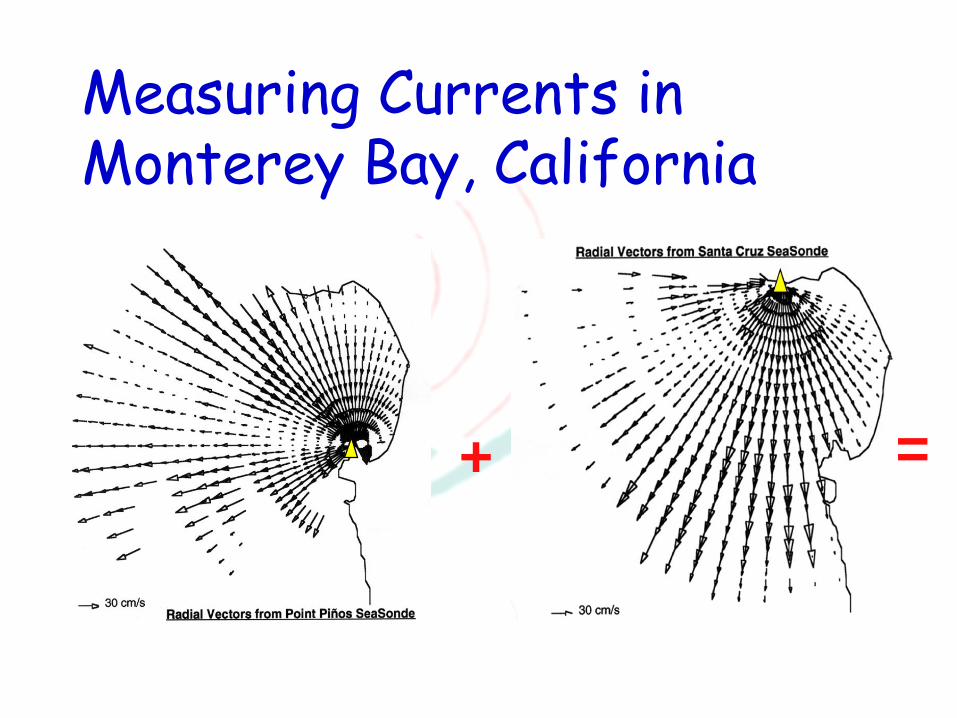
Measuring Currents in Monterey Bay, California
+ =
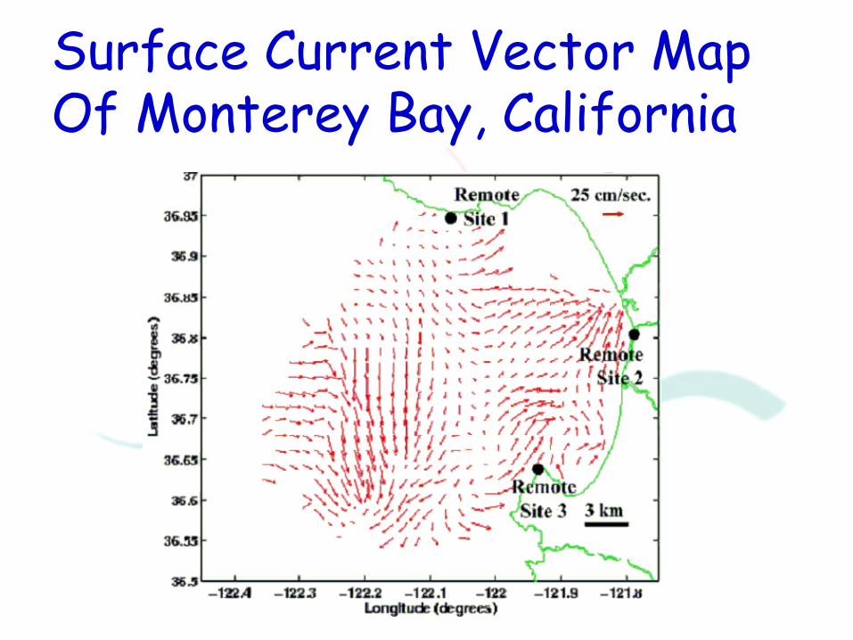
Surface Current Vector Map Of Monterey Bay, California
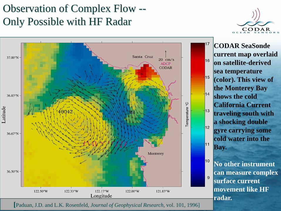
Observation of Complex Flow --
Only Possible with HF Radar
CODAR SeaSonde
current map overlaid
on satellite-derived
sea temperature
(color). This view of
the Monterey Bay
shows the cold
California Current
traveling south with
a shocking double
gyre carrying some
cold water into the
Bay.
No other instrument
can measure complex
surface current
movement like HF
radar.
[Paduan, J.D. and L.K. Rosenfeld, Journal of Geophysical Research, vol. 101, 1996]

CodarNor
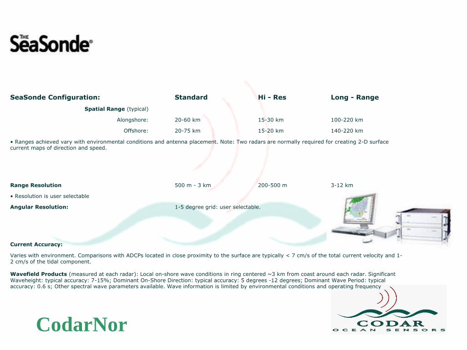
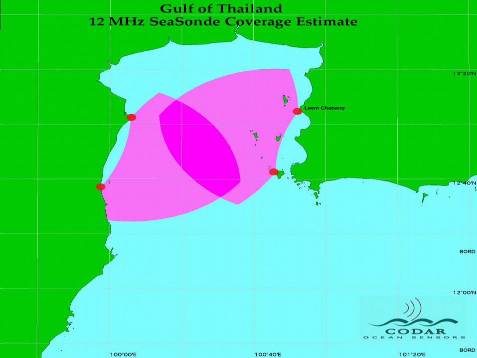
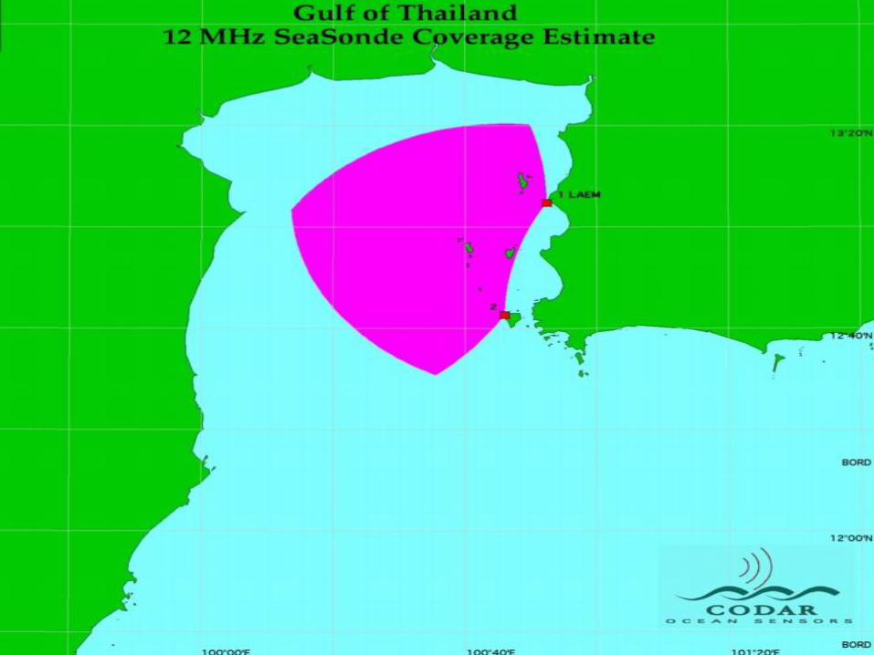
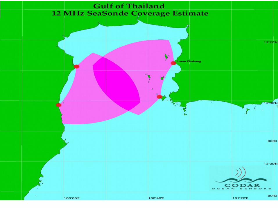
SeaSonde Configuration: Standard Hi - Res Long - Range
Spatial Range (typical)
Alongshore: 20-60 km 15-30 km 100-220 km
Offshore: 20-75 km 15-20 km 140-220 km
• Ranges achieved vary with environmental conditions and antenna placement. Note: Two radars are normally required for creating 2-D surface current maps of direction and speed.
Range Resolution 500 m - 3 km 200-500 m 3-12 km
• Resolution is user selectable
Angular Resolution: 1-5 degree grid: user selectable.
Current Accuracy:
Varies with environment. Comparisons with ADCPs located in close proximity to the surface are typically < 7 cm/s of the total current velocity and 1-2 cm/s of the tidal component. Wavefield Products (measured at each radar): Local on-shore wave conditions in ring centered ~3 km from coast around each radar. Significant Waveheight: typical accuracy: 7-15%; Dominant On-Shore Direction: typical accuracy: 5 degrees -12 degrees; Dominant Wave Period: typical accuracy: 0.6 s; Other spectral wave parameters available. Wave information is limited by environmental conditions and operating frequency

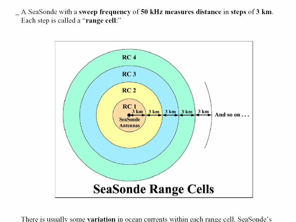
Resolutions obtained by the SeaSonde In distance: Determined by the bandwidth ~c/2B 25 KHz bandwidth gives a resolution of 6 km 50 KHz 3 km 100 KHz 1.5 km 500 KHz 300 m In bearing: More complicated signal processing ~2 degrees In speed: Doppler measurements, typical accuracy ~ 5- 10 cm/s
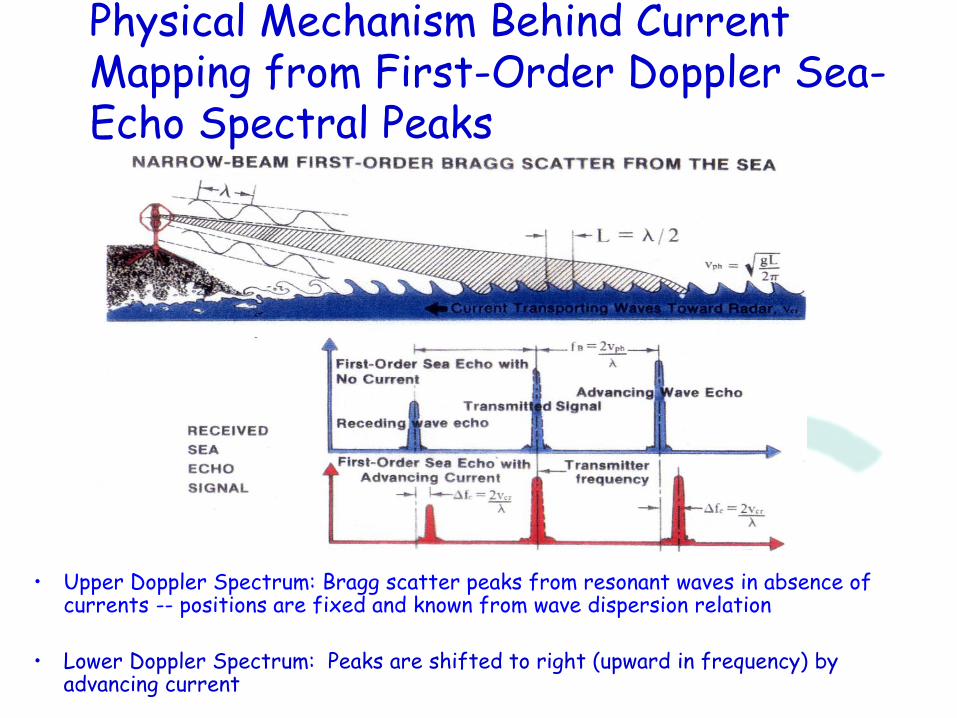
Physical Mechanism Behind Current Mapping from First-Order Doppler Sea-Echo Spectral Peaks
• Upper Doppler Spectrum: Bragg scatter peaks from resonant waves in absence of currents -- positions are fixed and known from wave dispersion relation
• Lower Doppler Spectrum: Peaks are shifted to right (upward in frequency) by advancing current
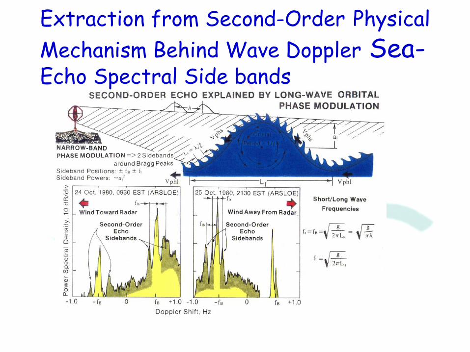
Extraction from Second-Order Physical
Mechanism Behind Wave Doppler Sea-Echo Spectral Side bands
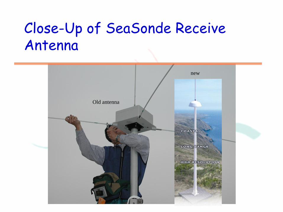
Close-Up of SeaSonde Receive Antenna
Old antenna
new
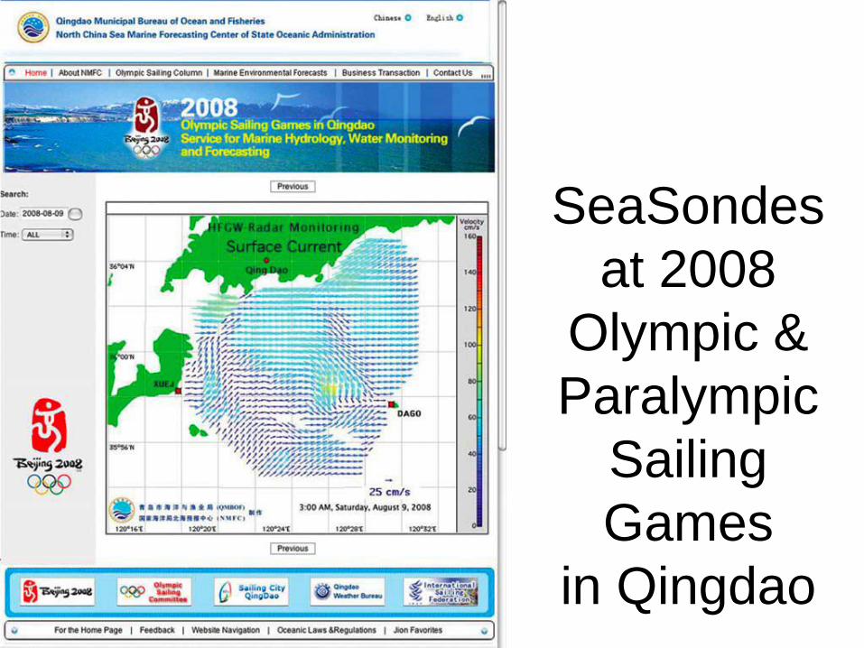
SeaSondes
at 2008
Olympic &
Paralympic
Sailing
Games
in Qingdao
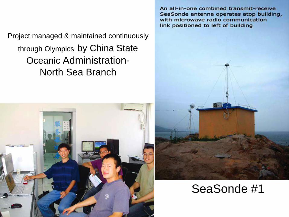
Project managed & maintained continuously
through Olympics by China State
Oceanic Administration- North Sea Branch
SeaSonde #1

Qingdao
SeaSonde #2

Korea
Korea
Japan
Japan
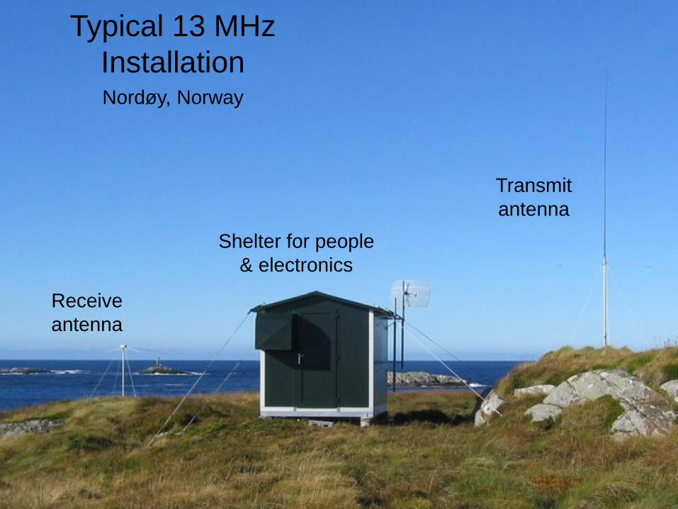
Nordøy, Norway
Typical 13 MHz
Installation
Shelter for people
& electronics
Receive
antenna
Transmit
antenna
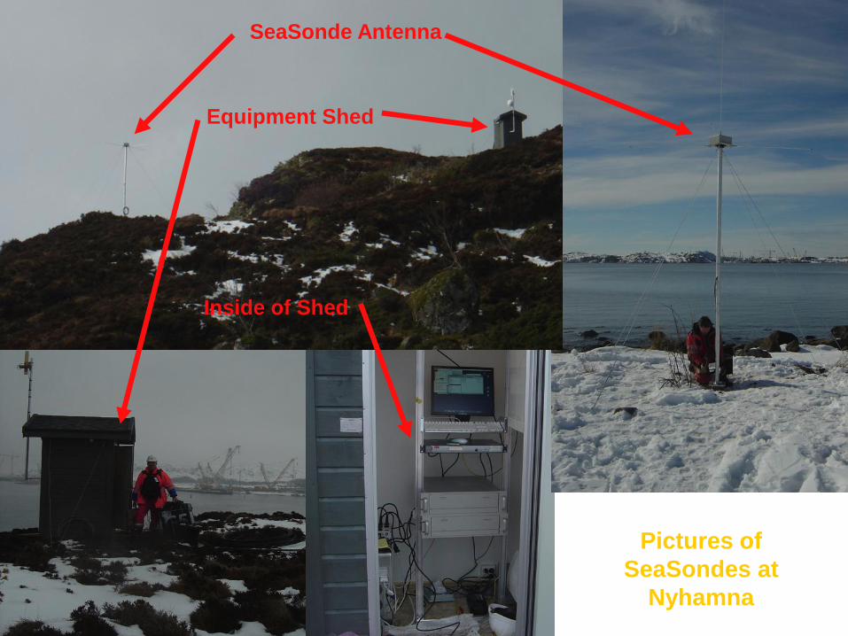
Pictures of
SeaSondes at
Nyhamna
SeaSonde Antenna
Equipment Shed
Inside of Shed
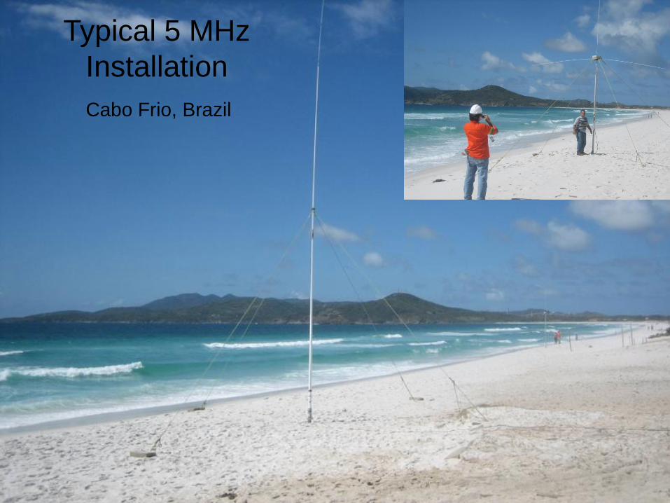
Typical 5 MHz
Installation
Cabo Frio, Brazil
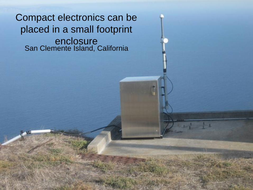
Compact electronics can be
placed in a small footprint
enclosure San Clemente Island, California

Complete 2-Site System Fits Easily into Small Van
Most SeaSondes
operate from
permanent sites, but
they are relocatable
Texas A&M Univ. has
been developing
portable trailers and
peripherals for rapid
response capability--
sponsored by TGLO
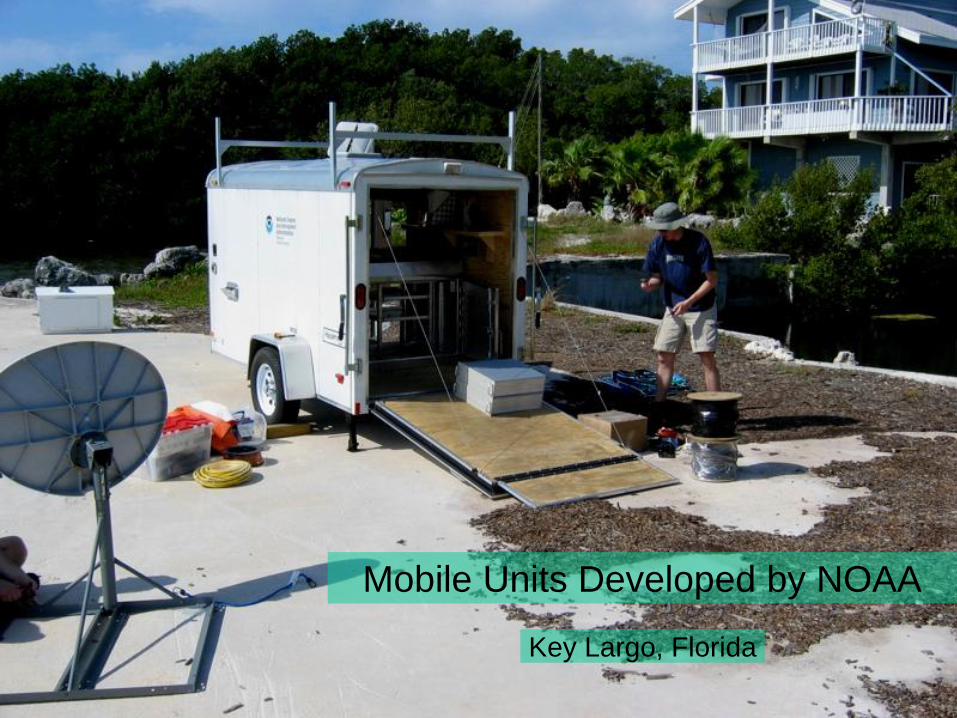
Mobile Units Developed by NOAA
Key Largo, Florida
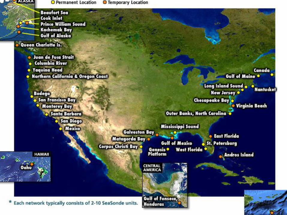
SeaSondes in the Americas


Norsk Hydro Uses 25 MHz SeaSonde inside Confined Fjord at Nyhamna, NO
Entrance to Fjord:
Long-period waves
from North Sea
are hazardous for
large tankers
Blow up of
region covered by
SeaSonde radars
at oil company
Gas plant
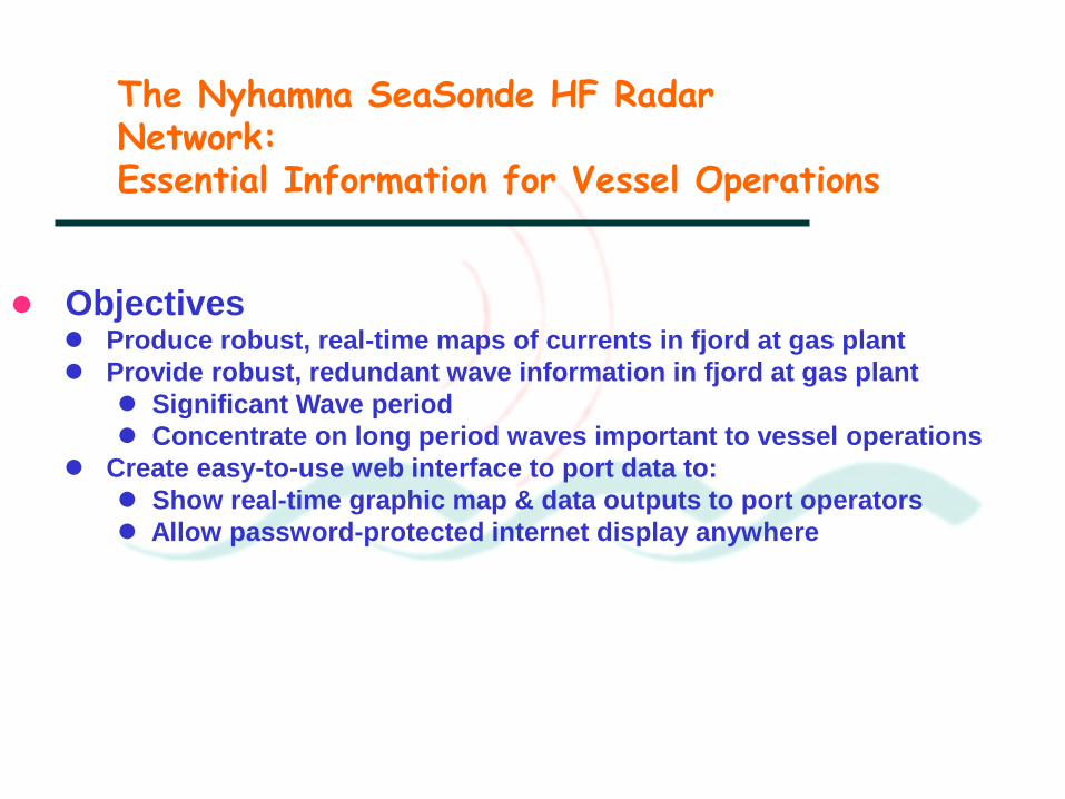
The Nyhamna SeaSonde HF Radar Network: Essential Information for Vessel Operations
Objectives Produce robust, real-time maps of currents in fjord at gas plant
Provide robust, redundant wave information in fjord at gas plant
Significant Wave period
Concentrate on long period waves important to vessel operations
Create easy-to-use web interface to port data to:
Show real-time graphic map & data outputs to port operators
Allow password-protected internet display anywhere
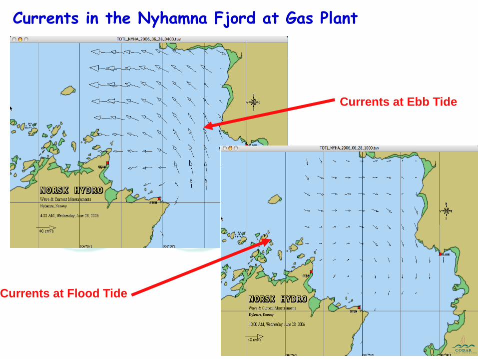
Currents in the Nyhamna Fjord at Gas Plant
Currents at Ebb Tide
Currents at Flood Tide

Wave Height Comparisons Nyhamna January 30 - February 4, 2007
Waveheights at all three radars Average radar & buoy waveheights
Waveheights do not vary significantly among the three radars
Buoy and radars capture the same higher-wave events
More radars give redundant wave data
Each radar is an independent & robust wave monitor
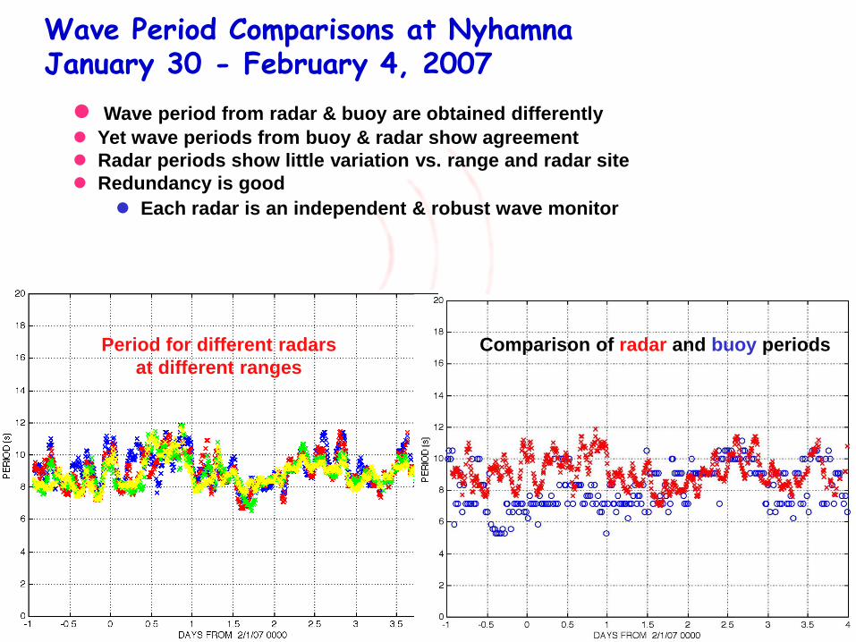
Wave Period Comparisons at Nyhamna January 30 - February 4, 2007
Period for different radars
at different ranges
Average radar & buoy waveheights
Comparison of radar and buoy periods
Wave period from radar & buoy are obtained differently
Yet wave periods from buoy & radar show agreement
Radar periods show little variation vs. range and radar site
Redundancy is good
Each radar is an independent & robust wave monitor
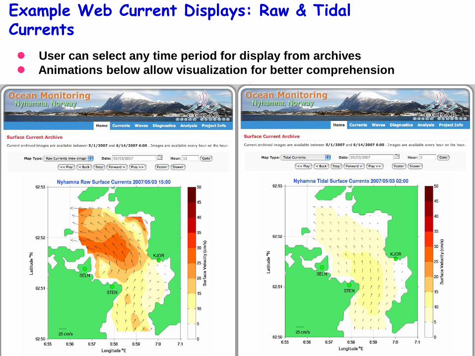
Example Web Current Displays: Raw & Tidal Currents
User can select any time period for display from archives
Animations below allow visualization for better comprehension
The First of Its Kind -- New Challenges Were
Encountered at Nyhamna and All Have Been Successfully Resolved
Three radars are operating simultaneously without interference
in very confined area (2 km across fjord)
Highest spatial resolution ever obtained with HF radars at 25
MHz (i.e., 300 meters requiring 500 kHz bandwidth -- no problems)
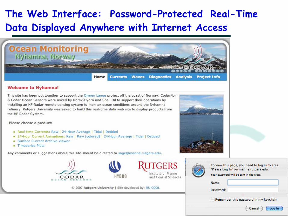
The Web Interface: Password-Protected Real-Time
Data Displayed Anywhere with Internet Access
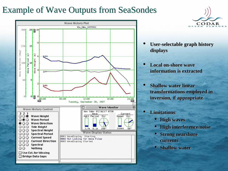
Example of Wave Outputs from SeaSondes
• User-selectable graph history
displays
• Local on-shore wave
information is extracted
• Shallow water linear
transformations employed in
inversion, if appropriate
• Limitations:
• High waves
• High interference/noise
• Strong nearshore
currents
• Shallow water
0 5 10 15 20 25 300
5
10
15
SIG
NIF
ICA
NT
WA
VE
HE
IGH
T (
M.)
HOURS FROM 12/14/01 00:00
0 5 10 15 20 25 300
5
10
15
20
PE
AK
PE
RIO
D,
S.
HOURS FROM 12/14/01 00:00
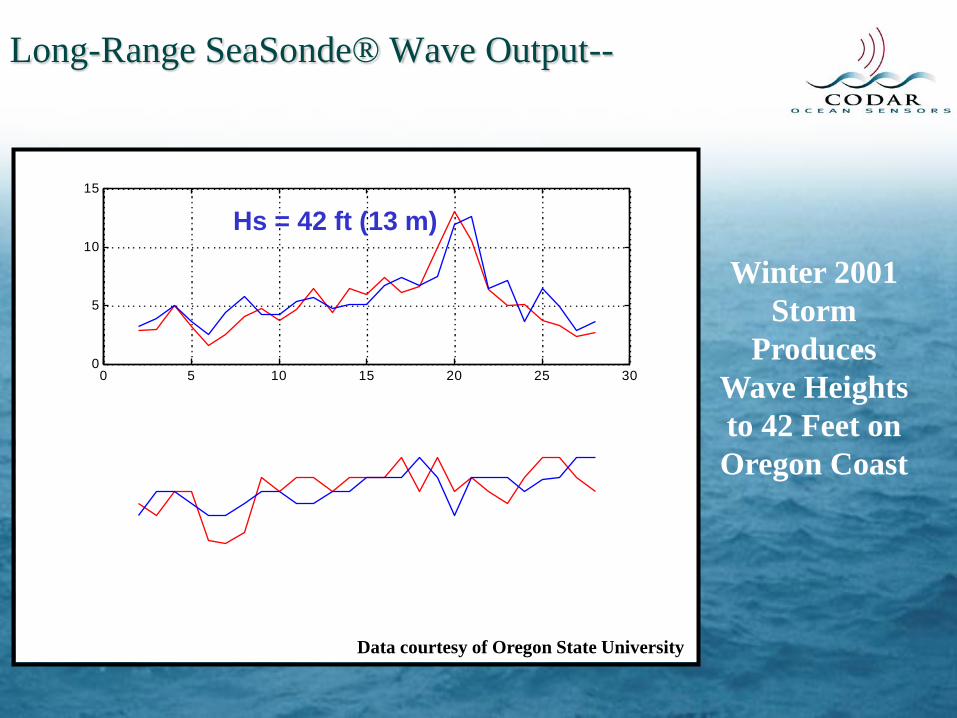
Long-Range SeaSonde® Wave Output--
Hs = 42 ft (13 m)
Data courtesy of Oregon State University
Winter 2001
Storm
Produces
Wave Heights
to 42 Feet on
Oregon Coast
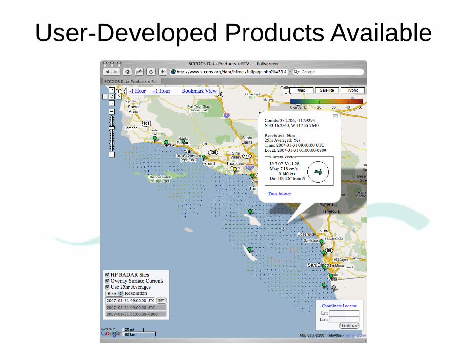
User-Developed Products Available

According to the Department of Marine and Coastal
Resources, Thailand loses about 5-20m of shore
each year along its 2,677km coast. The country now
has only 1.04 million rai (167,741ha), down from over
two million rai (322,580ha) in 1961.
Saving seashore districts such as Bang Khunthian is
crucial to Bangkok since the area is the capital's first
line of defence against rising sea levels. If the trend
continues, the city will be more vulnerable to flooding
and seawater contamination. As a result, local
residents will be at risk, particularly those who
depend on fishing and shrimp farming


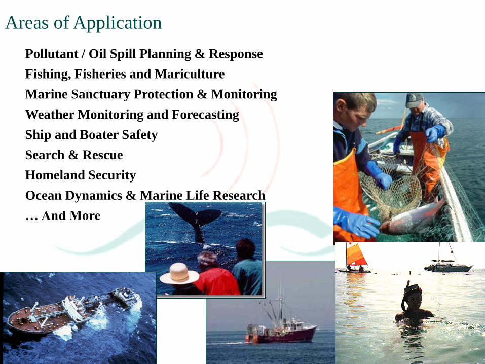
Pollutant / Oil Spill Planning & Response
Fishing, Fisheries and Mariculture
Marine Sanctuary Protection & Monitoring
Weather Monitoring and Forecasting
Ship and Boater Safety
Search & Rescue
Homeland Security
Ocean Dynamics & Marine Life Research
… And More
Areas of Application
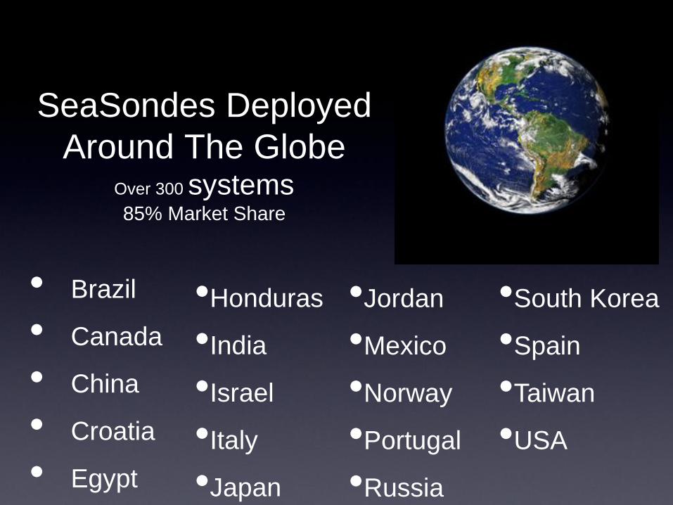
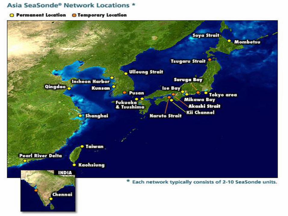
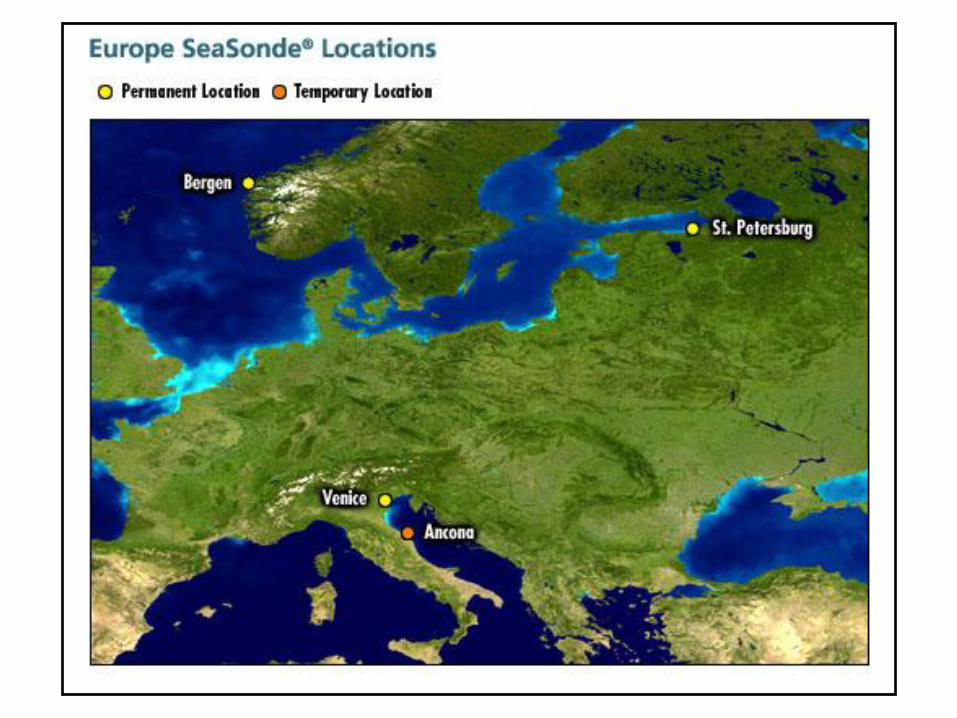
SeaSondes Deployed
Around The Globe Over 300 systems 85% Market Share
• Brazil
• Canada
• China
• Croatia
• Egypt
•Honduras
•India
•Israel
•Italy
•Japan
•Jordan
•Mexico
•Norway
•Portugal
•Russia
•South Korea
•Spain
•Taiwan
•USA

HF radar analyses methods presently in use are based on the
assumption of infinite water depth, and may therefore be
inadequate close to shore where we often have shallow waters.
Codar has developed an argorithm which can treat situations
when the radar echos returned from ocean waves that interact
with the ocean floor which means that a HF-radar can be used
to measure waves and currents when shallow water effects
become significant
2πd/L > 0.8
Summary Areas of Application • Marine sanctuary mapping,
monitoring, and protection
• Pollutant / Oil spill simulation
• Search and rescue
• Ocean dynamics- erosion applications
• Tsunami detection
• Wave measurements
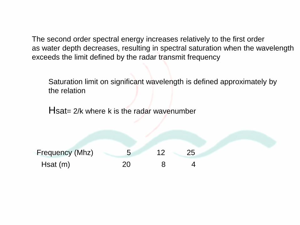
The second order spectral energy increases relatively to the first order
as water depth decreases, resulting in spectral saturation when the wavelength
exceeds the limit defined by the radar transmit frequency
Saturation limit on significant wavelength is defined approximately by
the relation
Hsat= 2/k where k is the radar wavenumber
Frequency (Mhz) 5 12 25
Hsat (m) 20 8 4
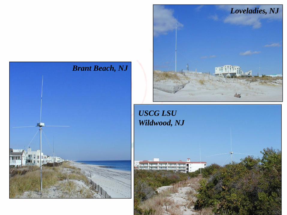
New Jersey
Installations
USCG LSU
Wildwood, NJ
Loveladies, NJ
Brant Beach, NJ
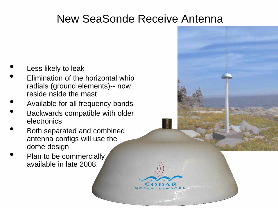
New SeaSonde Receive Antenna
• Less likely to leak
• Elimination of the horizontal whip radials (ground elements)-- now reside nside the mast
• Available for all frequency bands
• Backwards compatible with older electronics
• Both separated and combined antenna configs will use the dome design
• Plan to be commercially available in late 2008.
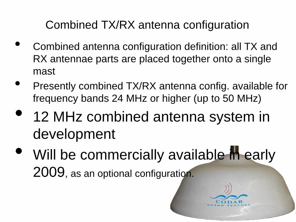
Combined TX/RX antenna configuration
• Combined antenna configuration definition: all TX and
RX antennae parts are placed together onto a single
mast
• Presently combined TX/RX antenna config. available for
frequency bands 24 MHz or higher (up to 50 MHz)
• 12 MHz combined antenna system in
development
• Will be commercially available in early
2009, as an optional configuration.

Related Documents