Hexmesh Corrosion in FCC Regenerators API Refractory Team 15 November 2010 By Rich Parkinson Copyright © 2010 UOP LLC All Rights Reserved

Welcome message from author
This document is posted to help you gain knowledge. Please leave a comment to let me know what you think about it! Share it to your friends and learn new things together.
Transcript

Hexmesh Corrosion in FCC Regenerators
API Refractory Team15 November 2010By Rich Parkinson
Copyright © 2010 UOP LLC All Rights Reserved

2 Copyright © 2010 UOP LLC All Rights Reserved
Background
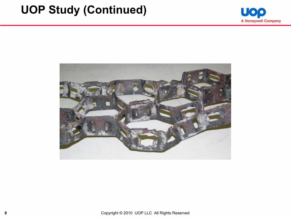
• In the past several years, severe corrosion of the abrasion resistant lining anchorage system has been discovered in many FCC Regenerators- UOP is aware of a dozen or more instances
• Failure of the anchorage system occurs in as little as 2 years, possibly even less- Often discovered due to blocked cyclone dipleg(s) or other
occurrences affecting the process - Sheets of hexmesh (or flexmesh), including the refractory
biscuits, can sometimes be pulled for the base metal by hand.
- Parts of the metallic anchorage can sometimes be crumbled by hand

3 Copyright © 2010 UOP LLC All Rights Reserved
Background
• Corrosion generally occurs in the upper portion of full burn regenerators, though it has been seen in several other locations- Typically the worst instances are in the primary cyclones- Has occurred in plenums and internal risers
• UOP initiated a study in 2009, which became a more formal process in 2010- Studied samples from a half dozen sites- Chemistry of metal and refractory was confirmed and the
chemistry of corrosion deposits determined

4 Copyright © 2010 UOP LLC All Rights Reserved
UOP Study
- A variety of analytical techniques were used, including:SEM (scanning electron microscope)Emission spectroscopyX-ray diffractionEDS (energy dispersive X-ray spectroscopy)ICP (induced coupled plasma spectroscopy)IC (ion chromatography)RAMAN spectroscopyTGA-MS (thermogravimetric analysis – mass spectrometry)Visual

5 Copyright © 2010 UOP LLC All Rights Reserved
UOP Study (Continued)
6 Copyright © 2010 UOP LLC All Rights Reserved
UOP Study (Continued)

7 Copyright © 2010 UOP LLC All Rights Reserved
UOP Study (Continued)

8 Copyright © 2010 UOP LLC All Rights Reserved
UOP Study (Continued)
• Thickness varies from 0.99 to 1.3 mm; original thickness was near 2mm

9 Copyright © 2010 UOP LLC All Rights Reserved
Study Findings
• Corrosion occurs to the back portions of the metal anchoring system, i.e., at or near it’s attachment point to the base metal
• Moving towards the surface of the lining, the corrosion becomes less
• At the surface there is no corrosion (i.e., where directly exposed to the process)- Discovery of damage is, therefore, difficult before the corrosion
has advanced- The process itself does not appear to be the cause
• Corrosion generally occurs on surfaces adjacent to refractory, but it does occur on surfaces between abutting hex strips
• Once the phenomena was identified, much earlier failures (perhaps as much as 20 years ago) were thought to be the same phenomena- No reliable samples exist to confirm early occurrences- Appears to be much more common now

10 Copyright © 2010 UOP LLC All Rights Reserved
Corrosion CharacterizationGeneral Trends
• Process gas itself does not appear corrosive- Conditions are different within/behind refractory
• Accelerated corrosion seemingly always associated with carburization of base metal
ProcessSide
Tab

11 Copyright © 2010 UOP LLC All Rights Reserved

12 Copyright © 2010 UOP LLC All Rights Reserved

13 Copyright © 2010 UOP LLC All Rights Reserved
Study Findings (Continued)
• Increased corrosion found in potential crevice locations:- Hexmesh/refractory
interface- Hexmesh/hexmesh
interfaceDirect contact with
refractory not required
• Little corrosion found on process-facing surface HexmeshRefractory
Corrosion
Process-facing surface

14 Copyright © 2010 UOP LLC All Rights Reserved
Corrosion Findings
• Corrosion phenomenon- Corrosion is a combination of oxidation, sulfidation, and carburization
Most of the corrosion products are oxides, predominantly iron and chromium; other products, such as iron sulfides are present, tooGeneralized rather than localized
- The corrosion process is not fully understood and may be a complex interrelationship of many factors
Appears to be highly dependant upon (very) localized environments
- Corroded sites are carburizedThis indicates that a more reducing atmosphere is present; the general atmosphere in the regenerator is highly oxidizing, therefore there is a localized differenceCarburization acts mostly as a marker for a reducing atmosphere but may be part of the corrosion process; could tie up chromium
- Stainless steel corrosion resistance is provided by a thin, tightly adhered, self repairing Cr-O layer
Forms in strongly oxidizing atmospheresSelf repairs with chromium from deeper in the metal plus oxygenDamage to this layer, such as may occur in a more reducing atmosphere where alternate reactions with chromium, such as chrome carbides allows base metal corrosionOxygen may combine with carbon, if present (burning of carbon to form CO). In a confined space, this may result in insufficient oxygen for Cr – O repair

15 Copyright © 2010 UOP LLC All Rights Reserved
Corrosion Findings (Continued)
- Corrosion products are oxides of iron and chromiumChromium oxide forms are thicker and more porous, thus (much) less protective than the thin adherent layer mentioned earlier. Requires a more reducing atmosphere
• More easily damaged by thermal expansion, thermal cycling, vibrations, etc
Iron oxides require damage to or non-protective form of chromium oxidesChromium is deleted near the metal surface, inhibiting formation of protective films
• Chromium may be tied up with carbon or other products• May be promoted by carburization or carburization may not be involved• Chromium in the metal is depleted, inhibiting formation/repair of the
protective layerCorrosion generally tracks to units with high(er) sulfur feeds, though not always

16 Copyright © 2010 UOP LLC All Rights Reserved
Corrosion Findings (Continued)
• Accelerated corrosion linked to impairment/breakdown of the protective Cr-oxide layer- Carburization and sulfidation present in areas of accelerated
corrosion suggest shift to more reducing conditions
Fe Cr SOptical Micrographs EDS Elemental Mapping

17 Copyright © 2010 UOP LLC All Rights Reserved
Metal
Refractory
Cr depletion
Cr-Fe-O
Cr-S
Fe-O
SEM Analysis of Scale

18 Copyright © 2010 UOP LLC All Rights Reserved
Corrosion Findings (Continued)
• Nearly all corrosion sites also contain FCC catalyst- Catalyst could supply carbon within the hot, confined,
environment, permitting the above described reaction- Iron sulfides around catalyst particles, possibly indicating a
stronger reducing environment
• The confined space is not readily replenished by the regenerator atmosphere and becomes more reducing- Perhaps due to presence and release of carbon and sulfur in
the void; depends upon carbon and sulfur levels, forms, temperature, diffusion rates, equilibrium levels, etc; all of which vary from point to point and shift at points.
- Oxygen level is low(er)- Different reactions predominate (e.g., carbon and sulfur
based vs chromium based) as the atmosphere becomes more reducing; inhibits protective layer formation

19 Copyright © 2010 UOP LLC All Rights Reserved
Corrosion Findings (Continued)
• The metallic surface, exposed to the regenerator environment, is exposed to the regenerator atmosphere and generally excess oxygen
• Moving higher in the regenerator means there is less oxygen in the atmosphere due to previous coke burning
• Afterburning or continued burning of adherent coke high in the regenerator also results in lower oxygen content
• Sulfur found diffused throughout the refractory, regardless of material, thus there is a ready source of sulfur. Sulfur not inrefractory mix – comes from environment

20 Copyright © 2010 UOP LLC All Rights Reserved
Corrosion Findings (Continued)
• FCC catalyst has been found at the hexmesh/refractory interface• Localized Fe-sulfide formation has also been associated with the presence of
FCC catalyst- Suggests shift to more reducing environment associated with catalyst ingress
FCC Catalyst Metal
Cr-oxide
Fe-sulfide
SFe Cr
SEM/EDS Cross-section Analysis

21 Copyright © 2010 UOP LLC All Rights Reserved
Corrosion Findings (Continued)
• Different refractory materials have been shown to absorb sulfur from the process gas- Sulfur pick-up is primarily in the refractory binder- Sulfur has been found through the entire thickness of
refractory biscuits, indicating a potential sulfur pathway behind the refractory lining
- This has been observed for both Ca-rich and Mg-rich refractory binder systems
Sulfur Elemental Map (EDS)

22 Copyright © 2010 UOP LLC All Rights Reserved
Potential Causes
• Among the Potential Causes Considered- Process changes
In general, the processes have not changedOccurrences in many units which operate a bit differently and are under different licenses make a common, perhaps unrecognized, process change unlikely
- Heavier, lower quality, feedsThis has occurred and may result in added catalyst coking and possibly more adherent cokeAdditional or larger amounts of impurities may be introducedMay result in somewhat higher temperatures in the Regenerators and may increase the possibility of afterburing.
- Changes in catalyst formulationCatalysts come from multiple vendors; it’s unlikely that an unrecognized but common change has occurredHowever, there may be some commonality with respect to the raw material sources so this cannot be entirely discounted
23 Copyright © 2010 UOP LLC All Rights Reserved
Potential Causes (Continued)
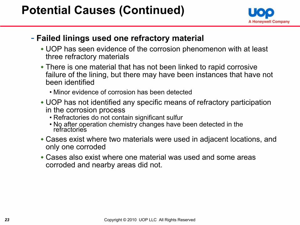
- Failed linings used one refractory materialUOP has seen evidence of the corrosion phenomenon with at least three refractory materialsThere is one material that has not been linked to rapid corrosive failure of the lining, but there may have been instances that have not been identified
• Minor evidence of corrosion has been detectedUOP has not identified any specific means of refractory participation in the corrosion process
• Refractories do not contain significant sulfur• No after operation chemistry changes have been detected in the
refractoriesCases exist where two materials were used in adjacent locations, and only one corrodedCases also exist where one material was used and some areas corroded and nearby areas did not.

24 Copyright © 2010 UOP LLC All Rights Reserved
Potential Causes (Continued)
- Failed linings used material for a specific manufacturing site or made in a specific time frame
The failed refractories were manufactured at a variety of sites and by several vendorsRefractory used in lining failures were manufactured over a period of at least 6 years. If the possibility of earlier, unidentified, failures is included the period is much longer
- Refractory chemistry, e.g., vanadium, sodium or other alkalis could contribute by forming low melting salts (e.g., with sulfur) thatdamages the stainless steel
Refractories vary in their sodium and alkali contentMelting could occur at FCC temperaturesThere have been reports of vanadium presence, but UOP has not detected vanadium
• Includes one sample with suspected vanadiumMore Na in some of the refractories present at corroded areas, but the available Na appears insufficient to support this corrosion
• There have been a couple of reports of sodium loss but UOP has not seen a lossThis type of corrosion doesn’t present as the actual corrosion looks nor does it explain the sulfidation or rate of corrosion

25 Copyright © 2010 UOP LLC All Rights Reserved
Potential Causes (Continued)
- Changes in refractory formulationRefractory manufacturers state that there have been no significant formulation changes, though changes in raw material sources are possibleCorrosion has occurred with several refractory materials
- Refractory InstallationIn nearly every case, void areas indicated incomplete filling of the hex were found where corrosion occurred.Voids create enclosed areas that may be conducive to creation of a locally more reducing atmosphere
• Possible that voids could be too small or too large to produce a more reducing atmosphere
• Differential thermal expansion and refractory PLC are insufficient to create the necessary voids (hasn’t been seen before)
• Catalyst in gaps indicates they are open during operationRefractory properties may affect installation and void formation
• Mix consistency (high or low stiffness)• Adherence to installation procedures (refractory manufacturer and contractor)
The method of ramming (pneumatic, thumbing, mallet) may be a factor. Due to other factors, it may not be possible to mandate a consistent installation method worldwide

26 Copyright © 2010 UOP LLC All Rights Reserved
Potential Causes (Continued)
- Anchor metallurgyConsider an anchor material that is more resistant to the corrosionHave seen corrosion with Types 304, 304H and 321 stainless steelUsed ASSET software to model resistance to carburization/sulfidation in a typical regenerator environment
• Based upon “Carbon Activity” which is a measure of the degree of reducing or oxidizing atmosphere.
» Low numbers are more oxidizing, high numbers are more reducing» Results are sensitive to even a small degree of reducing» Corrosion predictions consistent with those observed suggest a
carbon activity of 0.05 to perhaps 0.5, tending towards the lower end
• Modified the environment to investigate sensitivity of the result

27 Copyright © 2010 UOP LLC All Rights Reserved
ASSET(1) Corrosion Prediction
Carbon activity
Temperature(°F)
Pressure(atm)
Gas composition (mol%)
O2 H2O SO2 SO3 N2 CO2
0, 0.05, 0.1, 0.5 1
1375 2.0 2 10 0.3 0.03 70.67 17
Input conditions for corrosion calculation on various metals
(1) The Alloy Selection System for Elevated Temperature (ASSET), developed for Shell by Humberside Solutions Ltd, Suite 1410, 270 Scarlett Road, Toronto, Canada, M6N 4X7.

28 Copyright © 2010 UOP LLC All Rights Reserved
ASSET Corrosion Prediction
Input conditions for corrosion calculation on various metals – input screen

29 Copyright © 2010 UOP LLC All Rights Reserved
ASSET Corrosion Prediction
Materials Ranking based on corrosion rate (sulfidation/oxidation), mpy
AlloysCarbon activity (maximum being 1)
0 0.05 0.1 0.5 1333 8.27E-33 1.91 (2) 7.34 138 138347 4.82E-9 3.90 (3) 5.64 12.6 12.6317 2.86E-6 4.88 (4) 6.32 11.1 11.1825 4.63E-6 8.99 (8) 11.7 20.6 20.6316 5.74E-6 8.51 (7) 11.0 19.2 19.2304 1.63E-4 14.3 (10) 17.6 27.5 27.5310 2.49E-4 7.95 (6) 9.58 14.4 14.4330 3.07E-4 6.35 (5) 7.60 11.2 11.2800H 4.70E-4 10.1 (9) 12.1 18.0 18.0309 1.42E-2 0.79 (1) 0.85 0.99 0.99

30 Copyright © 2010 UOP LLC All Rights Reserved
Materials Ranking
• Materials Ranking in terms of sulfidation/oxidation resistance
Carbon activity
Rankings
0 347 (most resistant) > 304 > 310 > 330 > 309 (least resistant)
0.05 309 > 347 > 330 > 310 > 304
0.1 309 > 347 > 330 > 310 > 304
0.5 309 > 330 > 347 > 310 > 304
1 309 > 330 > 347 > 310 > 304
Special Notes:1. Alloys 333, 317, 316 and 825 should be avoided because Mo containing materials have the potential to form a volatile, low-melting temperature molybdenum oxide (MoO3) that can form at temperatures above 1300°F if oxygen is present.
2. Nickel-based alloys such as 800H and 825 should be avoided since they may not perform well in local reducing sulfurous conditions.

31 Copyright © 2010 UOP LLC All Rights Reserved
Potential Causes (Continued)
- Style of anchorageThe great majority of failures have occurred with hexmesh linings
• The very great majority of linings are hexmesh –the preferred anchorage method
• Lances – positive or negative?Some failures with flexmesh
• Hinge rod may make complete filling more difficult• Less weld to base metal; more gaps between base metal and mesh
Failure with hexalts has been seen
- Welding of hexmeshIn some instances welds were only on one side of the hex, rather than two spanning the metallic strip joint as specified by UOPWelding of every hex, and possibly welding three sides of each hex, may be beneficial
• At a minimum it will provide a more redundant anchoring system• One theory holds that the corrosion grows from one hex to another through
gaps beneath the hexes. Welding of three sides would close this path

32 Copyright © 2010 UOP LLC All Rights Reserved
Potential Factors (Continued)Weld pattern differences in same unit
Welds
Weld
Little Corrosion – Lining remained Intact
= Weld
Significant Corrosion – Lining spalled off

33 Copyright © 2010 UOP LLC All Rights Reserved
Refractory Analysis – Sample SummaryEffect of exposure to process conditions
• Both Type 1and Type 2 appear to absorb sulfur from the process gas• No clear relation between S, Na and volatile content and “good/bad” rating
Refinery Reported RefractoryType Location SO2 Level
(ppm) S Na Volatiles
Bad
A Type 1 Dipleg - 1st stage cyclone 2500 1.80 0.41 2.55
B Type 1 Regen Primary Cyclone 1.34 0.21 1.38
C Type 1 primary cyclone - - -
? Type 1 1.43 0.62 1.43
Good
A Type 1 Regen cyclone 2500 1.69 0.27 2.89
D Type 1 Regen Cyclone 900 0.01 0.716 0.33
EType 2 Regen Cyclone Dipleg 900 0.07 0.11 0.27
? Regen Cyclone 0.16 0.11 0.4
B Type 2 flue gas expansion joint 1.12 0.07 5.66
?
F Type 3 1500 / 770 0.52 0.18 1.24
GType 1 1st stage Regen Cyclone 0.06 0.05 0.31
Type 2 1st stage Regen Cyclone 0.05 0.05 0.21

34 Copyright © 2010 UOP LLC All Rights Reserved
FEED SULFUR VS TIME(Type 1 and 2 Refractory Material)

35 Copyright © 2010 UOP LLC All Rights Reserved
Refractory AnalysisEffect of exposure to process conditions
Technique Information General Comparison Observed Changes After Use
ICP, LECO C,S Chemical
• Type 2 consistently had higher Si than spec
• Both picked up appreciable amounts of sulfur
• Type 1 has more Na
XRD Structural
• Both primarily alpha alumina with minor amounts of mullite
• Both showed binder (Ca or Mg) oxides converting to sulfates
• Type 2 also has minor amounts of quartz and Al2SiO5 • Mullite content of Type 1reduced
• Crystobolite formed in both (slightly more evident with Type 1)
SEM/EDS ElementalDistributions
• Type 1 - numerous 50-micron Ca-rich particles
• Large binder (Ca or Mg) particles not present
• Type 2 - a couple 200-500-micron Mg-rich particles
• Binder elements (Ca or Mg) associated with S
• Type 1possibly has more uniform distribution of S in binder

36 Copyright © 2010 UOP LLC All Rights Reserved
Summary of Findings to Date
• Accelerated corrosion of hexmesh within and behind refractory may occur due to alteration of the gas environment at those locations- Environment appears more reducing in nature- Ensuing carburization and sulfidation contribute to impair
protective Cr-oxide formation and dramatically increase corrosion rate
• Corrosion appears to favor:- Units processing high sulfur feeds- Areas of high temperature
• Other “mechanical” factors may come into play as well- Installation quality may influence gap formation- Differences in weld pattern effect anchor strength/rigidity
and gap formation

37 Copyright © 2010 UOP LLC All Rights Reserved
Summary of Findings to Date (Continued)
• Catalyst ingress may be a contributor- Localized sulfide formation found around catalyst particles- Additional source of sulfur (besides from through refractory
absorption)- Possible source of carbon
Type of feed shown to influence burn characteristics, delayed burn behind refractory possible source of CO and heat
• Any potential role of refractory formulation on observed crevice corrosion still unclear

38 Copyright © 2010 UOP LLC All Rights Reserved
Summary of Possible Factors
• Gaps/Installation procedures (packing quality)- More gaps could enable increased scale formation/metal loss as well as
catalyst ingress- Workability of refractory could be a factor here- Sensitivity to deviations from suggested installation procedures different
for different refractories?
• Location / elevation in regenerator (local gas composition)- Gradients in gas composition / oxygen completion could impact some
areas greater than others
• Ingress of catalyst into crevices- Possible source of S and C- Can alter and isolate environment within/behind refractory- Type of feed can influence carbon on catalyst, delay burning- If present, premature reduction of de-Sox catalyst could also be a factor
39 Copyright © 2010 UOP LLC All Rights Reserved
Summary of Possible Factors (Continued)
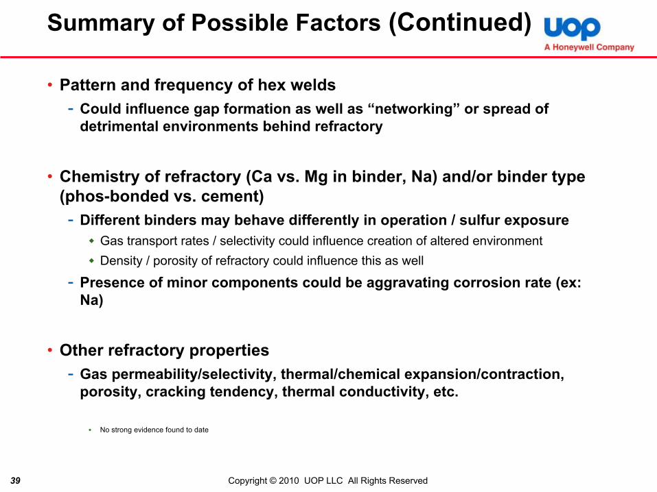
• Pattern and frequency of hex welds- Could influence gap formation as well as “networking” or spread of
detrimental environments behind refractory
• Chemistry of refractory (Ca vs. Mg in binder, Na) and/or binder type (phos-bonded vs. cement)- Different binders may behave differently in operation / sulfur exposure
Gas transport rates / selectivity could influence creation of altered environmentDensity / porosity of refractory could influence this as well
- Presence of minor components could be aggravating corrosion rate (ex: Na)
• Other refractory properties- Gas permeability/selectivity, thermal/chemical expansion/contraction,
porosity, cracking tendency, thermal conductivity, etc.
No strong evidence found to date

40 Copyright © 2010 UOP LLC All Rights Reserved
Interim UOP Approach
• What is UOP Recommending?- Use of the refractory material that has not been associated
with lining corrosion and failureLimited to areas were the problem may occurred, i.e., regenerators, standpipes, and flue gas systemsAll materials currently listed in UOP Specifications are acceptable for other areas
- Ensure that each hex is completely filled with refractory, i.e, “no” voids
Recommend close, constant, thorough installation supervision andinspection

41 Copyright © 2010 UOP LLC All Rights Reserved
Interim UOP Approach (Continued)
- No changes to the anchor metallurgyDifference in performance of stainless steels are not significant, especially considering the large tolerance on the model results and the unknown effect of trace elements in the atmosphereCost and availabilitySome alternatives are more brittle or possibly more susceptible to other phenomena such as sigma phase formationHigh nickel alloys may perform poorly in elevated temperature reducing atmospheres such as are present at the corrosion sitesSuggest avoiding Mo containing alloys (e.g., Type 316, 317, 904)because of possible volitization of the Mo, forming Mo oxides in the presence of oxygen at 1300 °F and greater

42 Copyright © 2010 UOP LLC All Rights Reserved
Additional Interim Possibilities
- Other possible measuresUse of combustion promoters to reduce the catalyst coke before reaching susceptible lining(s)Improved Stripper design to enhance removal of hydrocarbonsDeSOx catalyst to reduce the level of sulfur available
• May release sulfur in confined space atmosphere, worsening localconditions
Specify additional welding to the base metalOverfill of hexes – one report that corrosion did not occur where hexes were overfilled
• “overfill” could easily spallIf a change were considered, Type 347 would probably be the first alternative
• Appears to resist sulfidation/oxidation slightly better than other alloys• Stabilized, therefore resists sensitization much better than Type 304• Studies indicate Type 347 is more resistant to sensitization than Type 304L
or Type 321, and may not sensitize at temperatures over about 1050 –1100 °F.

43 Copyright © 2010 UOP LLC All Rights Reserved
Further Study Thoughts
• Further Study- Although corrosion may have been occurring for years, why has it become
more prominent and severe recently?
- What is the full cause (trigger, progression, etc) of the corrosionSequence of events
- How, or does, the refractory participateParticular formulation or property that allows or participates in corrosionChange in properties, e.g., coefficient of thermal expansion, upon sulfur saturation?Change in permeability or porosity?Moisture releases at temperature spikes
• Some studies show slight moisture exposure can result in stainless steel corrosion
- Develop more targeted remedial measuresLimit measures to certain temperature range, sulfur content, otherLimit refractory materials only where there is corrosion potential; flue gas systems have little or no carbon hence may have very low potential (no corrosion seen to date)Define what makes certain refractories “trigger” corrosion so as to better define which materials might Modify materials, operation, or additives to prevent corrosion; allow all refractories
- Way to detect corrosion before a major failure

44 Copyright © 2010 UOP LLC All Rights Reserved
API Input
• Attendees experiences with the subject corrosion?
• Thoughts re causes/reasons?
• Thoughts re remediation?
• UOP intends to continue their investigation; is this a subject that could be addressed under this Team’s auspices?- Industry wide problem; industry wide resolution- Several companies are conducting independent
investigations of varying depth
Related Documents


