Herschel SPIRE DPU DVM Ref.: SPIRE-IFS-PRJ-001593 Issue: Issue 1 Date: 9/04/2003 Page 1 of 39 IFSI CNR Herschel SPIRE DPU Design Verification Matrix Document Ref: SPIRE-IFS-PRJ-001593 Issue 1 Distribution List : K. King B. Swinyard J. Delderfield E. Sawyer R. Cerulli S. Molinari G. Liu’ Prepared by: Renato Orfei date: 9 April 2003 SPIRE-DPU-DVM-Issue1.doc

Welcome message from author
This document is posted to help you gain knowledge. Please leave a comment to let me know what you think about it! Share it to your friends and learn new things together.
Transcript

Herschel
SPIRE DPU DVM
Ref.: SPIRE-IFS-PRJ-001593
Issue:Issue 1
Date: 9/04/2003
Page 1 of 39
IFSI CNR
Herschel
SPIRE DPU Design Verification Matrix
Document Ref: SPIRE-IFS-PRJ-001593
Issue 1
Distribution List :
K. King
B. Swinyard
J. Delderfield
E. Sawyer
R. Cerulli
S. Molinari
G. Liu’
Prepared by: Renato Orfei date: 9 April 2003
SPIRE-DPU-DVM-Issue1.doc

Herschel
SPIRE DPU DVM
Ref.: SPIRE-IFS-PRJ-001593
Issue:Issue 1
Date: 9/04/2003
Page 2 of 39
IFSI CNR
Document Status Sheet
Issue Revision Date Reason for Change
Issue 1 9 April 2003 First issue
Document Change Record
Document Title: SPIRE DPU Design Verification Matrix
Document Reference Number: SPIRE-IFS-PRJ-001593
Document Issue/Revision Number: Issue 1
Section Reason For Change
Issue 1 First Issue
Herschel
SPIRE DPU DVM
Ref.: SPIRE-IFS-PRJ-001593
Issue:Issue 1
Date: 9/04/2003
Page 3 of 39
IFSI CNR
1 INTRODUCTION 6
1.1 General 6
2 DOCUMENTS 7
2.1 Applicable Documents 7 2.2 Reference Documents 7
3 Design Verification Matrix 8

Herschel
SPIRE DPU DVM
Ref.: SPIRE-IFS-PRJ-001593
Issue:Issue 1
Date: 9/04/2003
Page 4 of 39
IFSI CNR
Acronyms
AN ANalysis ASI Agenzia Spaziale Italiana (Italian Space Agency) AVM AVionic Model CDMS Central Data Management System CDMU Central Data Management Unit CGS Carlo Gavazzi Space EEPROM Electrically Erasable Programmable Read Only Memory EGSE Electrical Ground Support Equipment EIDP End Item Data Package EMC ElectroMagnetic Compatibility ESD Electro Static Discharge EQM Electrical Qualification Model DPU Digital Processing Unit FIRST Far Infra-Red and Sub-millimetre Telescope FCU Focal plane Control Unit FM Flight Model FP S/S Focal Plane sub-system FPU Focal Plane Unit FS Flight Spare HIFI Heterodyne Instrument for First HK House-Keeping HRS High Resolution Spectrometer HRSU High Resolution Spectrometer Unit HW HardWare IC Instrument Control ICD Interface Control Document ICE In Circuit Emulator ICU Instrument Control Unit I/F Interface ILT Instrument Level Test IN INspection LCU Local oscillator Control Unit LOA Local Oscillator Assembly LO S/S Local Oscillator sub-system

Herschel
SPIRE DPU DVM
Ref.: SPIRE-IFS-PRJ-001593
Issue:Issue 1
Date: 9/04/2003
Page 5 of 39
IFSI CNR
LOU Local Oscillator Unit NCR Non Conformance Report OBS On Board Software PA Product Assurance PACS Photoconductor Array Camera and Spectrometer PFM Proto Flight Model PROM Programmable Read Only memory QA Quality Assurance QM Qualification Model RD Review of Design S/C Spacecraft SM SiMilarity S/S Subsystem SPIRE Spectral and Photometric Imaging Receiver SU SimUlation SW SoftWare TBC To Be Confirmed TBD To Be Defined TBW To Be Written TE TEst TLP Transfer Layer Protocol TRB Test Review Board TRRB Test Readiness Review Board UR User Requirement URD UR Document VCD Verification Control Document WBS S/S Wide Band Spectrometer sub-system WBSU Wide Band Spectrometer Unit

Herschel
SPIRE DPU DVM
Ref.: SPIRE-IFS-PRJ-001593
Issue:Issue 1
Date: 9/04/2003
Page 6 of 39
IFSI CNR
1 INTRODUCTION
1.1 General
The content of this Design Verification Matrix is based on the DPU model philosophy and the DPU subsystem specification (AD03), the DPU product tree; it is consistent with the interface documents AD01, AD02 and AD08. This document allows a check of the requirements to be met by the DPU, both at CGS premises during acceptance tests of the boards and the following tests, to be sure that the DPU fulfils its mechanical, electrical and functional interfaces with the SPIRE subsystems and with the S/C subsystems.

Herschel
SPIRE DPU DVM
Ref.: SPIRE-IFS-PRJ-001593
Issue:Issue 1
Date: 9/04/2003
Page 7 of 39
IFSI CNR
2 DOCUMENTS
2.1 Applicable Documents
AD Name
01 Herschel/Planck Instrument Interface Document, part A
02 Herschel/Planck Instrument Interface Document, part B-Instrument SPIRE
03 Herschel SPIRE DPU Subsystem Specification Document
04 Herschel DPU/ICU Subsystem Development Plan
05 DPU/ICU P.A.Plan
06 DPU/ICU OBS Product Assurance Plan
07 DPU/ICU Switch-ON Procedure
08 SPIRE DPU Interface Control Document
09 Herschel PS-ICD
10 SPIRE DPU OBS URD
11 SPIRE DPU OBS User Manual
12 Herschel DPU/ICU Spacecraft Interface Acceptance Test Plan
2.2 Reference Documents
RD Title
01 DPU HW User manual
02 DPU Physical Properties Test Procedure
03 DPU Electrical Test Procedure
04 CPU BOARD Test Procedure
05 I/F BOARD Test Procedure
06 DC/DC BOARD Test Procedure
07 DPU-ICU Vibration Test Procedure
08 DPU-ICU Thermal Vacuum Test Procedure
09 DPU EMC Test Procedure
10 SPIRE DPU Box Interface Control Drawing

Herschel
SPIRE DPU DVM
Ref.: SPIRE-IFS-PRJ-001593
Issue:Issue 1
Date: 9/04/2003
Page 8 of 39
IFSI CNR
3 Design Verification Matrix
Document number: SPIRE-IFS-PRJ-001593 DPU DVM
Issue: 1
Date: 9 April 2003
Category: 2
Verification Methods
Requirement ID Requirement Title Requirement Text DM1 DM2 QM1 QM2 FM1 FM2 Remarks
IA-05.01-01 Identification and labelling
Each instrument is required to bear a unit identification label containing the following information: Project code; Unit identification code; Model (AVM, CQM, FM, FS)
IN IN IN
IA-05.01.03-01 Connector identification
Each equipment box is required to bear visible connector identification labels closely adjacent to the applicable connector
IN IN IN

Herschel
SPIRE DPU DVM
Ref.: SPIRE-IFS-PRJ-001593
Issue:Issue 1
Date: 9/04/2003
Page 9 of 39
IFSI CNR
IA-05.02.02-01 Instrument unit co-ordinate system
In order to provide a reference for the instrument focus, Centre of Gravity and Moment of inertia measurements, each instrument unit is required to have a right-handed Cartesian co-ordinate system. Its origin shall be in a reference hole(RH) in the unit mounting plane. The RH is defined as one of the unit fixation holes.
RD RD RD
IA-05.03.01-01 Instrument units envelopes
The instrument units shall be compatible with the maximum instrument envelopes as defined in IID-A figure 5.3.1-1 to 5.3.1-5 and table 5.3.1-1.
TE TE TE
IA-05.04-01 External Configuration Drawing
For each instrument unit, a configuration drawing is required to establish the mechanical interfaces with the spacecraft structure, harnesses and thermal hardware.
RD RD RD
IA-05.05.01-01 Mass tolerance for CQM
The mass of each of the CQM units shall be within 1% or 100 grams (whichever is less) of the estimated mass for that unit. On no account shall the instrument unit mass exceed the Project agreed maximum for that unit, current at the time of delivery to the Project.
NA NA NA NA
IA-05.05.01-02 Mass tolerance for FM
The mass of each of the FM units shall be within 1% or 100 grams (whichever is less) of the estimated mass for that unit. On no account shall the instrument unit mass exceed the Project agreed maximum for that unit, current at the time of delivery to the Project.
TE
IA-05.05.01-03 Mass tolerance for FS
In order to ensure free inter-changeability of FM and FS units the mass of each of the FS units shall be within 1% or 100 grams (whichever is less) of the mass measured for the equivalent FM units.
TE
Herschel
SPIRE DPU DVM
Ref.: SPIRE-IFS-PRJ-001593
Issue:Issue 1
Date: 9/04/2003
Page 10 of 39
IFSI CNR
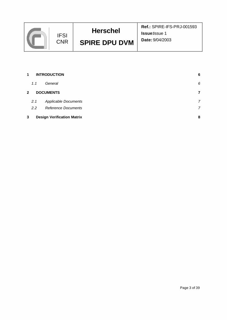
IA-05.05.02-02 CoG location and tolerance for the FM
The Center of Gravity of each unit shall be within a sphere of 1.0 mm radius around the best estimated location given in the units external configuration drawing, current at the time of delivery to the project
TE
IA-05.06.03.01-01 SVM Mechanical Interfaces
Attachment points, for SVM mounted units, shall provide a controlled contact. Design requirements are defined in IID-A section 5.6.3
RD IN IN
IA-05.07.03-01 SVM Thermal Interfaces
The nominal temperature ranges and interfaces for units mounted onto the SVM are defined in IID-A section 5.7.3.
TE TE
IA-05.09.05.01-01 Power Supply; Bus Voltage
Each of the scientific instruments will have to incorporate its own converter(s) (compatible with the main bus characteristics) to generate the required secondary voltages.
RD RD RD
IA-05.09.05.02-01 Power Supply; Signal characteristics
The instruments shall be designed to operate with nominal performance within the following steady state voltage limits: Minimum Voltage 26V Maximum Voltage 29 V
TE TE TE
IA-05.09.05.02-02 Power Supply; Survival voltage range
All the users of these power lines shall safely survive any standing or fluctuating voltage in the full range 0 V to 35V.
TE TE TE TBC: (Contract Vmax = 29V)
IA-05.09.05.03.01-01 Power Supply; Transient behaviour
The equipment shall operate with nominal performance when subject to a transient superimposed on the steady state bus as described in IID-A paragraph 5.14.3.8.
TE TE TE

Herschel
SPIRE DPU DVM
Ref.: SPIRE-IFS-PRJ-001593
Issue:Issue 1
Date: 9/04/2003
Page 11 of 39
IFSI CNR
IA-05.09.05.03.02-01 Power Supply; Ripple and Spikes
The ripple and spikes shall be less than (at Distribution Unit output connectors): - 300 mV peak to peak on 28 V lines. This peak to peak value is defined in a 50 MHz bandwidth
TE TE TE
IA-05.09.05.04-01 Power Supply; Distribution
Use of fuses shall be avoided. If absolutely needed, use of fuses shall be justified and request submitted to ESA for approval.
RD RD RD
IA-05.09.05.05-01 Power Supply; Bus Impedance
The bus impedance mask at the user interface (as function of frequency) is defined in IID-A section 5.9.5.5.
TE TE TE
IA-05.09.05.05-02 Power Supply; Self induced transients
Each instrument shall not be susceptible to voltage transients induced by its own current transitions, when connected to a 28Vdc voltage source (+2%, -1%) with the output impedance reported in IID-A paragraph 5.9.5.5.
TE TE TE
IA-05.09.05.06.01-01 Power Demand; Average
The average power is defined for an equipment as the maximum average power drawn from its dedicated power lines in the worstcase conditions.The maximum average is defined as the average during a period of 5 minutes shifted to any point in time where this average will yield a maximum and does not include peak power defined in IID-A sections 5.9.5.6.2 and 5.9.5.6.3.
RD RD
IA-05.09.05.06.02-01 Power Demand; Long Peak
To be defined as a long peak, the power demand shall last less than 5 minutes per 24 h (cumulated duration of individual peaks if any) and more than 100 ms. The peak value is defined as the integral mean during a period of 100 ms shifted to
RD TE TE

Herschel
SPIRE DPU DVM
Ref.: SPIRE-IFS-PRJ-001593
Issue:Issue 1
Date: 9/04/2003
Page 12 of 39
IFSI CNR
any point in time where the integral will yield a maximum.
IA-05.09.05.06.03-01 Power Demand; Short Peak
To be defined as a short peak, the power demand shall last less than 100 ms.The peak value is defined as the integral mean during a period of 1 ms shifted to any point in time where the integral will yield the maximum.
RD TE TE
IA-05.09.05.06.04-02 Power demand; inrush current profile
Figure 5.9.5-2 of IID-A gives the nominal current envelope.The inrush current requirements applicable to the instruments in terms of test conditions and success criteria are specified in § 5.14.7 of IID-A.
RD TE TE
IA-05.09.05.06.05-01 Power demand; Load Current Transitions
The instantaneous rate of change (dI/dt) shall not exceed 5.10^4 A/sec. Pulse repetition frequency shall not exceed 1Hz unless confined to the limits of admissible ripple current.
TE TE TE
IA-05.09.05.06.06-01 Power demand; Initial Electrical Status
After being switched of f for a minimum period of 10 sec and when switched on, equipments shall have an initial electrical status (except for latching relays if used), which is reproducible and identified. This status shall be safe; I.e. no degradation of nominal performance shall be caused if this initial status is kept for an unlimited time.
TE TE TE
IA-05.09.05.07-01 Instrument Converter frequency
The DC/DC converters shall be free running at nominal frequency 131kHz +/-10% (TBC).
TE TE

Herschel
SPIRE DPU DVM
Ref.: SPIRE-IFS-PRJ-001593
Issue:Issue 1
Date: 9/04/2003
Page 13 of 39
IFSI CNR
IA-05.10.01.01.01-01 Connector types; non-cryogenic
For non-coaxial signal connections at non-cryogenic temperatures CANNON-ITT connectors of type DxMA are defined. (x = A, B, C, D or E).
RD IN IN
IA-05.10.01.02-01 Connectors; identification
Connectors shall be clearly identified to prevent incorrect mating IN IN IN
IA-05.10.01.02-02 Connectors; housing connection
The housing of connectors shall be electrically connected to the connector shell.
IN IN IN
IA-05.10.01.02-03 Connectors; connector savers
Flight-quality connectors shall be protected against frequent mating/de-mating operations by connector savers. These savers shall be supplied with the instrument.
IN
IA-05.10.01.02-04 Connectors; locking
Connectors shall be mechanically locked to prevent inadvertent disconnection as part of the final integration process.
IN IN IN
IA-05.10.01.02-05 Connectors; signal categories
All units shall use dedicated connectors for the different signal categories as defined in chapter 5.10.2.4 of IID-A
RD IN IN
IA-05.10.01.02-06 Connectors; redundancy
Separate connectors shall be used for each of the redundant system, subsystem or unit branches.
RD IN
IA-05.10.01.02-07 Connectors; Cross-strapping
Cross-strapping shall be allowed RD RD

Herschel
SPIRE DPU DVM
Ref.: SPIRE-IFS-PRJ-001593
Issue:Issue 1
Date: 9/04/2003
Page 14 of 39
IFSI CNR
IA-05.10.01.03-01 Connector mounting
The physical position is to be indicated on the External Configuration Drawings and must be compliant with the minimum distances between connectors and mounting plane as given in Figure 5.10.1-1 of IID-A.
RD IN IN
IA-05.10.02.04-01 Harness design criteria
Signals between subsystems can be divided into the following categories: - Supply lines from power source to the users. - Digital signals. - Signals sensitive with respect to EMC (analogue signals) - RF signals (SPIRE coaxial) Signals of each of these categories shall be handled as follows: - Separation of categories shall be retained up to and inclusive of the interface connector - Separation of harness branches will be performed according to exp. signal classification - Separate bundles shall be used for each of the redundant systems, subsystems and unit branches - Twisted wires shall be routed through a connector on adjacent pins
RD RD RD
IA-05.10.03.01-01 Grounding Concept
The local grounding concept of the subsystem shall be "Distributed Single Point Grounding" (DSPG) system.
RD RD
IA-05.10.03.02-01 Grounding; return path
The spacecraft structure shall not be used as return path for power and signals.
RD TE TE
IA-05.10.03.03-01 Grounding to Structure
The grounding to structure shall not depend on the configuration of the electrical design.
RD RD

Herschel
SPIRE DPU DVM
Ref.: SPIRE-IFS-PRJ-001593
Issue:Issue 1
Date: 9/04/2003
Page 15 of 39
IFSI CNR
IA-05.10.03.04-01 Isolation between Primary Power and S/C Structure
Equipment using primary DC power shall maintain at least 1MOhm DC isolation shunted by not more than 50 nF between: - Primary power high line and structure - Primary power return line and structure before any grounding of the primary reference is made.
TE TE TE
IA-05.10.03.05-01 Isolation between Primary and Secondary Power Line
Secondary power lines, inherently galvanic-isolated from the primary power by DC-to-DC converters or isolation transformers, shall maintain an isolation of at least 1 Mohm shunted with a capacity lessthan 5 nF between primary power return lines before any grounding of the secondary reference is made
TE TE TE
IA-05.10.03.06-01 Secondary power Grounding
Each user secondary power return shall be connected to a single ground (ground point/ground plane). This ground point/ground plane shall be connected to chassis.
TE TE TE
IA-05.10.03.07-01 Grounding for Equip. distributing Sec. Power
When a single converter via multiple windings supplies one or more equipments, the secondary power network shall be grounded to a single location within the supplied unit(s). One secondary power output shall not be distributed to more than one unit.
NA NA NA
IA-05.10.04.01-01 Bonding; Fault Current
Bonding provisions and bonding interfaces shall be designed to carry fault currents of 1.5 times the subsystem equipment protection device rating for an infinite time without damage and thermal hazard. Magnesium shall not be used as path for fault currents.
TE TE TE

Herschel
SPIRE DPU DVM
Ref.: SPIRE-IFS-PRJ-001593
Issue:Issue 1
Date: 9/04/2003
Page 16 of 39
IFSI CNR
IA-05.10.04.02-01 Bonding; Lifetime Bonding provisions and bonding interfaces shall be designed to be corrosion resistant, i.e. to maintain their performance in the specified environment and operations for the specified lifetime. Bonding of dissimilar materials shall be avoided (same group in the electrochemical series) unless special precautions are taken to avoid stress corrosion.
IN IN
IA-05.10.04.03-01 Direct and Indirect Bonding
The use of conductive mounting surfaces is the preferred method of bonding. Use of bond straps (indirect bonding) shall be implemented in addition to the direct contact.
RD RD
IA-05.10.04.04-01 Bonding of equipment to Structure
Equipment cases shall be bonded to the structure of the hosting spacecraft via the equipment mounting feet. The contact area of the bottom side of each foot shall not be less than 1 cm^2. The DC resistance between the equipment chassis and the hosting spacecraft structure shall not exceed 10 mOhm. This level applies for both directions of polarity across the bond.
IN TE IN TE
IA-05.10.04.06-01 Characteristics of the Bonding Surfaces
Flat, clean and conductive surfaces shall be used for bonding. The permitted surface finishes are: - clean metal ( except magnesium) -Gold plate on the base metal - Alodine 1200 or similar according to MIL-C-5541.
RD IN IN
IA-05.10.04.07-01 Unstable bonding Anti-friction bearings, wire-mesh vibration cushion mounts, lubricated bushing etc. shall not be used to implement bonding. Bolts and screws shall not be used as intentional grounding path.
IN IN

Herschel
SPIRE DPU DVM
Ref.: SPIRE-IFS-PRJ-001593
Issue:Issue 1
Date: 9/04/2003
Page 17 of 39
IFSI CNR
IA-05.10.04.08-01 Bonding; Compression fasteners
Bonding connection shall not be compression fastened through non-metallic materials.
IN IN
IA-05.10.04.09-01 DC Resistance between Adjacent Faces of Chassis
The DC resistance between any two adjacent faces of the equipment chassis shall not exceed 2.5 mOhm. This level applies for both directions of polarity across the bond.
IN IN
IA-05.10.04.10-01 Bonding Lug To allow bonding each unit shall provide a bonding stud. This shall consist of a stud M4 x 6 located close to the mounting plane. The bonding lug shall be easily accessible when the unit is integrated on the spacecraft and shall be clearly marked on the mechanical interface drawings. The DC resistance between this stud and the underside of the mounting feet shall not exceed 2.5 mohm for both directions of polarity.
TE TE TE
IA-05.10.04.11-01 Serial connection of bonding strap
Serial connection of two or more bonding straps is not permitted. (Except MLI)
IN IN
IA-05.10.04.12-01 Secondary power reference
The DC impedance between the unique secondary power reference inside the equipment and the bonding lug shall be less than 5 mOhm DC and have a low inductance.
TE TE TE

Herschel
SPIRE DPU DVM
Ref.: SPIRE-IFS-PRJ-001593
Issue:Issue 1
Date: 9/04/2003
Page 18 of 39
IFSI CNR
IA-05.11.01-01 Telemetry Data rate The total instrument average data rate over 24hrs, including science and periodic and non-periodic HK data and formatting overheads for TM packets - must not exceed 130kbits/s for Herschel and for the Planck mission, compatible with the link margins and formatting requirements. Burst Data rate up to 300kbps can be handled for a pre-defined time.
RD TE TE
IA-05.11.01-02 Subframe budget allocation
The instrument shall comply with the Sub-frame budget allocation as discussed in section 5.11.1 of IID-A.
RD TE TE
IA-05.11.03-01 Timing A unique on-board time, the Central Time Reference (CTR), is maintained at spacecraft level and distributed to the instruments in order to time-tag their data, which will be embedded in their telemetry packets.
TE TE
IA-05.11.04-01 Telecommand Data Rate
The maximum telecommand rate will be 4 kbit/sec. The maximum command rate to the instrument will be 2 TeleCommand packets per instrument per second.
TE TE
IA-05.11.05-01 Polling Strategy, nominal mode
With reference to Figure 5.11.5-1. Slot number 21 will be used for polling control, if the instrument has data to be retrieved then it shall write to this slot.
RD TE TE
IA-05.11.05-02 Polling Strategy, burst mode
This mode is principally the same as the nominal mode except that the same user is polled in consecutive sub-frames.
TE TE

Herschel
SPIRE DPU DVM
Ref.: SPIRE-IFS-PRJ-001593
Issue:Issue 1
Date: 9/04/2003
Page 19 of 39
IFSI CNR
IA-05.11.07-01 CDMS Interface Circuits
The interface circuits for the spacecraft data bus have been def ined according to MIL 1553 B. The S/C data bus will provide routing of the instrument TM packets up to 300kbps maximum, and it will support delivery of TC packets to each instrument at the maximum rate (see IID-A section 5.11.4). Details of the data protocol and interface are defined in the H/P Packet Structure ICD (SCI-PT-ICD-07527)
RD TE TE
IA-05.11.10-01 Addresses on 1553 bus
The 1553 busses addresses for instrument data processing units or instrument control units shall comply with section 5.11.10 of IID-A
RD TE TE
IA-05.12.05-01 Pointing correction from prime instrument
The spacecraft will communicate, on-board and to ground, a request for pointing correction from the prime instrument per single observation. After reception of pointing correction from the instrument, the spacecraft will autonomously readjust its position accordingly.
RD TE TE
IA-05.12.06-01 On-Target Flag For the HERSCHEL mission an on target flag will be generated when the commanded target has been acquired.
TE TE
IA-05.13.02-01 On-board software standards
Instrument on-board software shall comply with the ESA software standard ECSS-E 40B and amended by the Guide to applying the ESA software engineering standards to small software projects BSSC(96)2.
RD RD RD

Herschel
SPIRE DPU DVM
Ref.: SPIRE-IFS-PRJ-001593
Issue:Issue 1
Date: 9/04/2003
Page 20 of 39
IFSI CNR
IA-05.13.02-02 Standardisation of on-board software
Standardisation of on-board software and its development and verification tools, with other instruments for the same satellite, will significantly ease the in-flight maintenance. Therefore: - a preferred language for on-board software development shall be used - the software and development and verification tools shall be standardised. - development shall be in close contact with the other instruments. - development shall use common SW modules/routines (e.g. libraries) for common functionality, e.g. on-board memory loading/dumping
RD RD RD
IA-05.13.02-03 On-board software; Memory assignment
In-flight maintenance requires that functionally distinct areas of memory shall be assinged to: - programme code - fixed constants - variable parameters.
RD RD RD
IA-05.13.02-04 On-board software; modification of parameters
It shall be possible to modify individual software parameters or constants by command from the ground.
TE TE TE
IA-05.13.02-05 On-board software; actions taken on-board
Information to indicate all actions of operational significance taken by on-board software in a complete, unambiguous and timely manner shall be available in the telemetry
TE TE TE

Herschel
SPIRE DPU DVM
Ref.: SPIRE-IFS-PRJ-001593
Issue:Issue 1
Date: 9/04/2003
Page 21 of 39
IFSI CNR
IA-05.13.02.03-01 On-board memory loading
It shall be possible to load any memory area from the ground. Any telecommand packet needed to uplink any area of memory shall be self-consistent in that: - a successful load shall not depend on previous packets - if a packet is rejected, it may be up linked on its own at a later time
TE TE
IA-05.13.02.04-01 On-board memory dumping
Any memory area shall be accessible for dumping on ground request.The dump request shall specify the start address and length of the dump. Only a single command packet shall be required, even if several telemetry packets are required to convey the dump area to the ground
TE TE
IA-05.14.01.01-01 Signal Interface Grounding
For external interfaces, all the signal driver outputs shall be referenced to the signal ground and all the input terminals of the signal receivers shall be isolated from the ground. Only exceptions are the RF interfaces using coaxial cables and the low -level telemetry and telecommand lines that are permitted to have single/ended-single/ended interface (as dictated by the PSS)
RD RD
IA-05.14.01.02-01 Signal Isolation (Common Mode Isolation)
The receiver interface circuitry shall be designed to provide isolation between its input terminals and the receiver grounding reference that shall not be less than the mask given in IID-A figure 5.14.1-1
RD RD
IA-05.14.01.03-01 Signal Reference Signals shall never use the primary power ground as reference. The secondary power reference shall constitute the user reference unless a further galvanic isolation stage is implemented.
RD TE TE
IA-05.14.01.04-01 Allowed Interface The allowed interface topologies are listed in IID-A table 5.14.1-1 RD RD

Herschel
SPIRE DPU DVM
Ref.: SPIRE-IFS-PRJ-001593
Issue:Issue 1
Date: 9/04/2003
Page 22 of 39
IFSI CNR
Topologies
IA-05.14.01.05-01 Noise Immunity Discrete and digital interfaces shall be designed for noise immunity with both level and time discrimination.
RD RD
IA-05.14.01.06-01 In Band Response Analogue and digital circuits shall be designed to not respond to signals out of their own intentional frequency bandwidths.
RD RD
IA-05.14.01.07-01 In Band Transmission
The transmission bandwidths shall be limited to the minimum extent possible.
RD RD
IA-05.14.01.08-01 Filter Location Filters shall be placed at the source end of the interface if it is dictated so by the receiver time response or if additional noise suppression is required.
RD RD
IA-05.14.02.01-01 Definition of EMC classes
Power and signal lines shall be grouped into the following EMC classes: Class 1: Primary/Secondary Power Class 2: Digital Signals, High Level Analogue Signals Class 3: Low level Sensitive Analogue Signals Class 4: RF Signals (via coaxial cables, tri-axial cables, etc.)
RD RD RD
IA-05.14.02.06-01 Pin allocation on connectors
Allocation of wires with different EMC classes to the same connector shall be avoided to the maximum possible extent. When wires with different EMC classes have to be allocated to the same connector, they shall be physically separated as much as possible within the connector
RD IN IN

Herschel
SPIRE DPU DVM
Ref.: SPIRE-IFS-PRJ-001593
Issue:Issue 1
Date: 9/04/2003
Page 23 of 39
IFSI CNR
IA-05.14.02.10-01 Cable Shield Terminations
Cable shield shall be grounded at both the ends to the equipment case at each end. The preferred method of grounding shields is through a conductive back-shell that makes good electrical contact to the equipment case.
RD TE TE
IA-05.14.02.12-01 DC resistance between back-shell and structure
The DC resistance between the plug connector back-shell and the structure in the vicinity of the equipment shall be less than 10 mOhm.
TE TE TE
IA-05.14.02.15-01 DC resistance: shield ground pin and chassis
If the shielding ground is implemented via dedicated pin, the DC resistance between any shield ground pin and the equipment chassis shall not exceed 2,5 mOhm. The connection of the shield ground pin to case shall be as short as possible. The maximum allowable length is 8 cm
TE IN TE IN TE
IA-05.14.02.18-01 Conductive Connector Caps
All electrical connectors not engaged shall be covered with aconductive cap.
IN IN
IA-05.14.02.19-01 Equipment Chassis Apertures, venting holes
The equipment case shall not contain any apertures other than those that are required for connectors, sensor viewing or out-gassing vents. If out-gassing vents are required, they shall be as small as possible (less than 5 mm diameter) and shall be located close to the equipment mounting plane, I.e. spacecraft structure ground.
RD RD
IA-05.14.02.20-01 Grounding Diagram
Grounding diagrams shall be established at both equipment and subsystem level.
RD RD

Herschel
SPIRE DPU DVM
Ref.: SPIRE-IFS-PRJ-001593
Issue:Issue 1
Date: 9/04/2003
Page 24 of 39
IFSI CNR
IA-05.14.03.01.01-01 CE Power Lines; Differential Mode
Narrow Band conducted emission Differential Mode in the frequency range 30 Hz - 50 MHz generated by the subsystem equipment on each primary power line shall not exceed the limits defined in IID-A section 5.14.3.1.1
TE TE TE
IA-05.14.03.01.02-01 CE Power Lines; Common Mode, Freq. Domain
Narrow Band conducted emission Common Mode in the frequency range 10 kHz - 50 MHz generated by the subsystem equipment on the primary power lines shall not exceed the limits defined in section 5.14.3.1.2 in IID-A
SU TE TE
IA-05.14.03.01.03-01 CE Power Lines; Differential Mode, Time Domain
Differential Mode, time domain current ripple and spikes on the primary power bus of the subsystem equipment shall be less than defined in section 5.14.3.1.3 in IID-A.
TE TE TE
IA-05.14.03.02-01 CE Signal bundles; Common mode
The conducted Emission Common Mode on individual Signal Bundles of the subsystem shall be measured from 10 kHz to 50 MHz. Measurement shall be used to establish the limits for Conducted Susceptibility Common Mode current injection on the same bundles.
TE TE
IA-05.14.03.03-01 CS Power lines; Differential Mode-Steady State
The subsystem equipment shall not exhibit any malfunction, degradation of performance or deviation beyond the tolerance in its individual specification when sinusoidal voltage with amplitude, as defined in section 5.14.3.3 of IID-A, is injected into the subsystem equipment power leads in the frequency range 30 Hz - 50 MHz.The frequency sweep rate shall not be faster than 5 min/decade.
TE TE

Herschel
SPIRE DPU DVM
Ref.: SPIRE-IFS-PRJ-001593
Issue:Issue 1
Date: 9/04/2003
Page 25 of 39
IFSI CNR
IA-05.14.03.04-01 CS Power Lines; Common Mode-Steady State
The subsystem equipment shall not exhibit any malfunction, degradation of performance or deviation beyond the tolerance in its individual specification when a sinusoidal common mode current are injected in both the subsystem equipment power leads via Bulk Current Injection.The Injection shall be in accordance with the limits as defined in IID-A section 5.14.3.4
TE TE TE
IA-05.14.03.05-01 CS Signal Bundles; Common Mode Current
The subsystem equipment shall not exhibit any malfunction, degradation of performance or deviation beyond the tolerance in its individual specification when sinusoidal common mode current of amplitude 6 dB higher than the common mode emission measurement (see IID-A section 5.14.3.2) is injected into the signal bundles.
TE TE TE
IA-05.14.03.06-01 CS Signal Refeference; Common Mode Voltage
The subsystem equipment shall not exhibit any malfunction, degradation of performance or deviation beyond the tolerance in its individual specification when sinusoidal voltages with 2 Vpp amplitude are applied between the subsystem equipment signal reference and the ground plane in the frequency range 50 kHz - 50 MHz. The sweep rate shall not be faster than 5 min./decade.
TE TE TE
IA-05.14.03.07-01 CS Signal Reference; Common Mode Voltage Transient
The subsystem equipment shall not exhibit any malfunction, degradation of performance or deviation beyond the tolerance in its individual specification when transient voltages, as defined in IID-A section 5.14.3.7, are applied between the equipment signal reference and the ground plane.
TE TE TE

Herschel
SPIRE DPU DVM
Ref.: SPIRE-IFS-PRJ-001593
Issue:Issue 1
Date: 9/04/2003
Page 26 of 39
IFSI CNR
IA-05.14.03.08-01 CS Power Lines; transients due to switching
The subsystem equipment shall not exhibit any malfunction, degradation of performance or deviation beyond the tolerance in its individual specification when transient voltages, as defined in IID-A section 5.14.3.8, are applied to the subsystem equipment input power leads.
TE TE TE
IA-05.14.03.09-01 NB E-Field Radiated Emission
Narrow band electric fields generated by the subsystem equipment and measured at 1 m distance shall not exceed the limits as defined in IID-A section 5.14.3.9, in the frequency range 14 kHz to 18 GHz.
TE TE TE
IA-05.14.03.10-01 NB E-Field Radiated Susceptibility
The subsystem equipment shall not exhibit any malfunction, degradation of performance or deviation beyond the tolerance indicated in its individual specification when it is irradiated with 2 V/M, 1 kHz amplitude modulated (30% AM) in the frequency range 14 kHz to 18 GHz.
TE TE TE
IA-05.14.03.11-01 H-Field Radiated Emission
Narrow -Band magnetic fields generated by the subsystem equipment and measured at 1 m distance shall not exceed the limits as defined in IID-A section 5.14.3.11, in the frequency range 30 Hz to 50 kHz.
TE TE TE
IA-05.14.03.12-01 H-Field Radiated Susceptibility
The subsystem equipment shall not exhibit any malfunction, degradation of performance or deviation beyond the tolerance indicated in its individual specification when it is irradiated with a magnetic field of 140 dBpT in the frequency range 30 Hz to 50 kHz.
TE TE TE

Herschel
SPIRE DPU DVM
Ref.: SPIRE-IFS-PRJ-001593
Issue:Issue 1
Date: 9/04/2003
Page 27 of 39
IFSI CNR
IA-05.14.03.13-01 Arc Discharge Susceptibility
No malfunction, degradation of performance or deviation beyond the tolerance indicated in its individual specification shall occur when the subsystem equipment and its interface lines are exposed to a repetitive electrostatic arc discharge of at least 15 mJ energy/ 15 kV. The current rise time shall be less than 10 ns. If damage risks are envisaged for interface circuits, the voltage can be reduced down to 4 kV but the energy shall remain 15mJ.
TE TE
IA-05.14.07-01 Plug-in and inrush current measurement
The plug-in and inrush current shall be measured in accordance to section 5.14.7 of IID-A.
TE TE TE
IA-05.15.01-01 Transport container
The Focal Plane Unit, Warm electronic Units and Interconnecting harness shall be transported in transport containers as described in IID-A sections 5.15.1.1 or 5.15.1.2.
IN IN
IA-05.15.02-01 Cleanliness The Focal Plane Unit, Warm electronic Units and Interconnecting harness transport containers shall be exposed to an clean room environment as described in IID-A sections 5.15.2.1 or 5.15.2.2.
IN IN
IA-05.15.02.04-01 Out-gassing properties of material
The material used to build the instruments shall be below the outgassing properties as presented in section 5.15.2.4 of IID-A.
RD RD
IA-05.16.01-01 Pressure environment
The instrument shall withstand the pressure environment as defined in section 5.16.1 of IID-A.
RD RD

Herschel
SPIRE DPU DVM
Ref.: SPIRE-IFS-PRJ-001593
Issue:Issue 1
Date: 9/04/2003
Page 28 of 39
IFSI CNR
IA-09.04.01.02.04-03 SVM Design Limit Loads
The flight limit loads to be applied for the structural design of the units on the SVM, considering in addition the safety factors (IID-A 9.4.1.2.3), are: case 1: longitudinal 25 g, lateral 20 g case 2: NA.
TE
IA-09.04.01.02.05-02 Structural stiffness for units on SVM and CVV
The structural stiffness of the LOU and the units on the SVM shall be designed to be greater than 140 Hz (any axis). This is including the margins as defined in IID-A sect 9.4.1.2.5
TE
IA-09.05.02-01 Test level tolerances
Maximum tolerances on tests shall be applied in accordance to those listed in table 9.5.2-1 of IID-A.
IN IN
IA-09.05.03.03.02-03 SVM Units Qualification Sine Vibration
For the units at the SVM the Qualification Sine Vibration levels are: Longitudinal: 5 - 100 Hz; 25 g Lateral: 5 - 100 Hz; 20 g Sweep rate: 2 Oct/Min.
TE
IA-09.05.03.03.02-06 SVM Units Acceptance Sine Vibration
The LOU Acceptance Sine Vibration levels are Longitudinal: 5 - 100 Hz; 20 g Lateral: 5 - 100 Hz; 16 g Sweep rate: 4 Oct/Min.
TE
IA-09.05.03.03.02-07 Low level sine vibration
Low level sine test shall be performed to determine resonance frequencies to evaluate the behaviour of the test fixture and item integrity. Resonance search shall be carried out before and after vibration test for each axis between 5 to 2000 Hz with a level of 0.5 g (sweep rate: 2 oct/min).
TE TE

Herschel
SPIRE DPU DVM
Ref.: SPIRE-IFS-PRJ-001593
Issue:Issue 1
Date: 9/04/2003
Page 29 of 39
IFSI CNR
IA-09.05.03.04-03 SVM Qualification Random Vibration
For the units on the SVM the Qualification Random Vibration levels are: Normal to mounting planel 20 - 100 Hz ; +3 dB/Oct 100 - 300 Hz; 0.20 g^2/Hz 300 - 2000 Hz; -5 dB/Oct g(rms):9.88 Other axis 20 - 100 Hz ; +3 dB/Oct 100 - 300 Hz; 0.1 g^2/Hz 300 - 2000 Hz; -5 dB/Oct g(rms): 6.99 Qualification duration is 2 min. per axis.
TE
IA-09.05.03.04-06 SVM Acceptance Random Vibration
For the units on the SVM the Acceptance Random vibration levels shall comply with table 9.5.3-5 of IID-A. Acceptance levels = Qual. Levels / 1,5625 Acceptance duration is 1 min. per axis
TE
IA-09.05.04.03.01-01 Thermal vacuum test
The thermal vacuum test is required to evaluate and demonstrate the functional performance under vacuum of the instrument units.
TE TE
IA-09.05.04.04-01 Thermal cycling test
Thermal cycling tests will be performed in order to demonstrate that the instruments and its units are able to withstand without degradation and under vacuum a number of thermal cycles representative of the lifetime of the instruments.
TE TE

Herschel
SPIRE DPU DVM
Ref.: SPIRE-IFS-PRJ-001593
Issue:Issue 1
Date: 9/04/2003
Page 30 of 39
IFSI CNR
IA-09.05.04.05-01 Thermal shock test A thermal shock test will be conducted to verify that the instruments or the units can withstand a rapid cool-down under vacuum from room temperature to the minimal temperature defined in the IID-B. The PI shall establish what is the minimal duration of the cool-down still compatible with the unit/instrument. However, this duration shall be no greater than 5 hours for Herschel, and TBD hours for Planck.
TE
IB-05.01-01 Unit Identification code
The project identification code allocated for SPIRE units, connectors and harness is defined in IID-B section 5.1
IN IN IN
IB-05.04-01 External Configuration Drawings
For each unit the mechanical interface, thermal and physical property requirements shall be defined in the respective external configuration drawings. See figures 5.4-1 to 5.4-15 of IID-B for these drawings.
IN IN IN
IB-05.05-01 Sizes and Mass Properties
Each unit shall comply with the maximum dimensions- and mass allocation as defined in IID-B section 5.5.
TE TE TE
IB-05.06.03-01 Warm Units Mechanical Interface
Units mounted on the SVM will have attachment points for fixation to the equipment platform. Units with a mass <1.5 kg will not have more than 4 of these points. For units with requirements for more of these points, the number shall be agreed by the project.
IN IN
IB-05.07.03-01 Warm Units Temperatures and Stability
The required operating temperatures and stability for the warm units at the interface of the units with the mounting platform or parts thereof are defined in IID-B section 5.7.3.
TE TE

Herschel
SPIRE DPU DVM
Ref.: SPIRE-IFS-PRJ-001593
Issue:Issue 1
Date: 9/04/2003
Page 31 of 39
IFSI CNR
IB-05.09.01-02 Power-up Sequence
The power-up sequence of the units shall be implemented in the SPIRE switch-on procedure. Upon power-up the units shall automatically set-up in Stand-by mode, according to section 5.9.5.1 of IID-B.
TE TE
IB-05.09.03-01 Power dissipation of units on the SVM
The maximum heat dissipations of the units mounted on the SVM are defied in IID-B section 5.9.3 .
TE TE TE
IB-05.09.05-01 Load on the Main Bus
The power load on the 28V main bus for the instrument units are defined in IID-B section 5.9.5
TE TE TE
IB-05.09.05.01-01 Instrument modes The status of the instrument units in the various instrument modes are defined in IID-B section 5.9.5.1.
TE TE TE
IB-05.09.05.02-01 Main power interface circuits
The main power interface circuit is defined in IID-B section 5.9.5.2. RD RD RD
IB-05.10.01-01 Connectors The instrument connectors for the S/C interfaces harness are specified in section 5.10.2.1. The connectors for the instrument internal harnesses are specified in section 5.10.2.2 of IID-B.
RD IN IN
IB-05.10.02.01-01 S/C Harness The instrument interfaces to the S/C harness are specified in section 5.10.2.1.
RD IN IN
IB-05.10.02.02-01 Instrument harness The interconnecting instrument harnesses are specified in section 5.10.2.2.
RD IN IN

Herschel
SPIRE DPU DVM
Ref.: SPIRE-IFS-PRJ-001593
Issue:Issue 1
Date: 9/04/2003
Page 32 of 39
IFSI CNR
IB-05.10.04-01 Grounding The SPIRE instrument with its many units and interfaces shall apply a distributed single point grounding scheme as defined in IID-B section 5.10.4.
RD RD RD
IB-05.10.05-01 Bonding of Units All units, located in the SVM, are to be bonded to structure via the equipment mounting feet, as specified in IID-A section 5.10.4.4. To allow bonding tests, each unit is provided with a bonding stud, according to IID-A section 5.10.4.10.
IN IN
IB-05.11.01.01-01 Telemetry Rate The instrument shall be designed to work well within the maximum allowed average data rates of 2Kbps for uncompressed housekeeping data and 98 Kbps science data.
TE TE
IB-05.11.01.02-01 Data-bus rate For the purpose of possible, short duration, higher instruments data rates the bus interconnecting the instrument and the Data-handling subsystem shall have the capability of handling a telemetry rate of 300 Kbps.
TE TE TE
IB-05.14.03-01 SPIRE Frequency Plan
The frequencies used within SPIRE together with the sensitivity to interference and power levels are defined in IID-B section 5.14.3.
RD TE TE
IB-05.15.05-01 Cleanliness At delivery to ESA, the instrument cleanliness shall comply with the maximum contamination levels as specified in section 5.15.3 of IID-B.
IN
IC-04.04-01 CDMS interface The command/data interface between the S/C CDMS and the DPU shall be compliant with the 1553-bus interface, as defined in the Packet Structure ICD.
TE TE TE

Herschel
SPIRE DPU DVM
Ref.: SPIRE-IFS-PRJ-001593
Issue:Issue 1
Date: 9/04/2003
Page 33 of 39
IFSI CNR
IC-04.04-02 Command/data interface configuration
The command/data interface between the DPU and the other sub-systems shall be compliant with the Instrument ICD.
TE TE TE
IC-04.04-03 Command/data interface clock-rates
The command/data interface clock-rates shall be compliant with the Instrument ICD.
TE TE TE
IC-04.04-04 Command/data interface signal characteristics
The command/data interface signal characteristics shall be compliant with the Instrument ICD.
TE TE TE
IC-04.04.01-02 Command interface protocol
The command protocol and timing shall be compliant with the Instrument ICD.
TE TE TE
IC-04.04.01-03 Subsystem addresses
The sub-system addresses for the command and housekeeping protocol shall be compliant with the Instrument ICD.
TE TE TE
IC-04.04.02-01 Housekeeping interface
The Housekeeping protocol and timing shall be compliant with the Instrument ICD.
TE TE TE
IC-04.04.03-01 Science and Housekeeping interface circuits
The Science and Housekeeping interface circuits shall be compliant with the Instrument ICD.
TE TE TE

Herschel
SPIRE DPU DVM
Ref.: SPIRE-IFS-PRJ-001593
Issue:Issue 1
Date: 9/04/2003
Page 34 of 39
IFSI CNR
IS-04.01.01-02 Observation timeline
All instrument operations shall be timed through time tags. TE TE TE
IS-04.01.02-04 The pointing of the telescope
A peak-up mode shall involve the evaluation of the spectrometer outputs to compute a relative pointing correction.
TE TE
IS-04.01.02-05 The pointing of the telescope
The pointing correction shall be communicated to the spacecraft CDMS for inclusion in the AOCS pointing offset.
TE TE
IS-04.02.03.03-05 Focal Plane Beam Steering Mirror Parameters
The Beam Steering Mirror frequency and throw shall be adjustable via DPU command.
TE TE
IS-04.03.01-01 Redundancy approach
The DPU shall be fully redundant and when one is commanded ON by the S/C the other is in COLD redundancy state.
AN AN
IS-04.03.02-01 Power distribution The power distribution shall comply with figure 5.9.1-1 of IID-B [AD-01]
RD RD
IS-04.03.03-01 Grounding concept The grounding concept of the instrument is defined in the IID-B, Section 5.10.4 (AD-01).
RD RD RD
IS-04.03.04-01 Instrument modes The SPIRE instrument shall have an Off mode. In this mode all power is removed from the instrument.
TE TE
IS-04.03.04-02 Instrument modes The SPIRE instrument shall have a ON mode. The DPU is ON TE TE

Herschel
SPIRE DPU DVM
Ref.: SPIRE-IFS-PRJ-001593
Issue:Issue 1
Date: 9/04/2003
Page 35 of 39
IFSI CNR
IS-04.03.04-03 Instrument modes The SPIRE instrument shall have a Stand-by mode. The DPU is ON TE TE
IS-04.03.04-04 Instrument modes The SPIRE instrument shall have a Parallel mode. The DPU is ON
TE TE
IS-04.03.04-05 Instrument modes The SPIRE instrument shall have a Serendipity mode. The DPU is ON
TE TE
IS-04.03.04-06 Instrument modes The SPIRE instrument shall have a Cooler Recycling mode. The DPU is ON
TE TE
IS-04.03.04-07 Instrument modes The SPIRE instrument shall have a PHOT observing mode. The DPU is ON
TE TE
IS-04.03.04-08 Instrument modes The SPIRE instrument shall have a SPEC observing mode. The DPU is ON
TE TE
IS-04.03.05-01 Instrument operations
All sequencing of instrument operation shall be by the execution of commands in DPU.
TE TE
IS-04.03.05-02 Instrument operations
The DPU shall have:
- 3 Low Speed serial bi-directional bus command interfaces with the subsystems;
RD TE

Herschel
SPIRE DPU DVM
Ref.: SPIRE-IFS-PRJ-001593
Issue:Issue 1
Date: 9/04/2003
Page 36 of 39
IFSI CNR
- 3 High Speed mono-directional interfaces from the subsystems to the DPU.
IS-04.03.05-03 Instrument operations
Synchronisation of the subsystems shall be through commands on this I/F.
TE TE
IS-04.03.05-04 Instrument operations
To control the instrument with the limited uplink data volume, macro expansion or table look-ups shall be used.
RD TE TE
IS-04.03.06-01 Data handling The division of data handling tasks between the S/S and the DPU shall be according to the SPIRE Specification ICD.
RD
IS-04.04.01-01 DCU Subsystem The DCU Sub-system shall generate housekeeping data as required. RD TE TE
IS-04.04.01-02 MCUSubsystem The MCU Sub-system shall generate housekeeping data as required. RD TE TE
IS-04.04.01-03 SCU Subsystem The SCU Sub-system shall generate housekeeping data as required. RD TE TE
IS-04.04.01-04 DPU Subsystem The DPU Sub-system shall generate housekeeping data as required. RD TE TE
IS-04.04.05-01 DPU Subsystem The DPU shall interface with the CDMS via a 1553B bus interface as specified in Appendix 9 of the Packet Structure ICD (AD-9) and as specified in the applicable documents therein.
TE TE TE
IS-04.04.05-02 DPU Subsystem The DPU shall receive tele-command packets from the spacecraft CDMS, check and acknowledge them as specified in the Packet Structure ICD (AD-9).
TE TE TE

Herschel
SPIRE DPU DVM
Ref.: SPIRE-IFS-PRJ-001593
Issue:Issue 1
Date: 9/04/2003
Page 37 of 39
IFSI CNR
NB: in DPU emergency mode there will be no TC acknowledge
IS-04.04.05-03 DPU Subsystem The DPU shall execute the tele-commands, as specified in the SPIRE OBS User Manual.
TE TE TE
IS-04.04.05-04 DPU Subsystem The DPU shall, as a result of the tele-command execution, send commands or sequences of commands to the other sub-systems, as specified in the SPIRE OBS User Manual
TE TE TE
IS-04.04.05-05 DPU Subsystem The DPU shall collect housekeeping data from itself and the other sub-systems, as specified in the SPIRE OBS User Manual.
TE TE TE
IS-04.04.05-06 DPU Subsystem The DPU shall collect science data from the subsystems as specified in SPIRE OBS User Manual.
RD TE TE
IS-04.04.05-07 DPU Subsystem The DPU shall execute on-board Test procedures, as specified in SPIRE OBS User Manual.
TE TE TE
IS-04.04.05-08 DPU Subsystem The DPU shall execute spectroscopy measurements, as specified in SPIRE OBS User Manual.
RD TE TE
IS-04.04.05-09 DPU Subsystem The DPU shall execute peak-up procedures, as specified in SPIRE OBS User Manual.
TE TE TE
IS-04.04.05-10 DPU Subsystem The DPU shall perform health checking by monitoring housekeeping data, as specified in SPIRE OBS User Manual.
TE TE TE

Herschel
SPIRE DPU DVM
Ref.: SPIRE-IFS-PRJ-001593
Issue:Issue 1
Date: 9/04/2003
Page 38 of 39
IFSI CNR
IS-06.01-01 Radiation All hardware shall withstand the radiation environment as specified in AD-03 without failure or significant degradation in performance and in accordance with the guidelines given in Section 9.5.7 of AD-02.
RD
IS-06.04-01 Cleanliness The cleanliness levels for particulate and molecular contamination shall comply with Table 6.4-1 (TBC).
IN IN IN
IS-07.01.01-01 Life time The instrument shall be designed for a mission lifetime of 3,5 years. RD
IS-07.01.01-02 Life time The instrument shall be designed for a ground operational lifetime of 2 years.
RD
IS-07.01.01-03 Life time The instrument shall be designed for a ground storage lifetime of 2 years.
RD
IS-07.01.02-01 Maintainability The hardware design shall be such that it is easy accessible for maintenance and repair.
IN
IS-07.01.03-01 Interchangeability The hardware design shall be such that flight and flight-spare items are interchangeable.
RD
IS-07.01.04-01 Safety SPIRE safety requirements shall comply with section 7 in AD-07. RD
IS-07.01.05-01 Reliability The probability of survival corresponding the operational duration shall be at least 95 % (EOL) for the DPU.
AN
IS-07.01.05-02 Reliability All units shall be designed so that no sequence of commands can cause permanent damage to hardware.
RD

Herschel
SPIRE DPU DVM
Ref.: SPIRE-IFS-PRJ-001593
Issue:Issue 1
Date: 9/04/2003
Page 39 of 39
IFSI CNR
IS-07.02.06-01 Materials and processes selection.
The selection of materials and processes shall be in accordance with AD05 section 3.
IN
IS-07.02.07-01 Venting Venting holes shall be provided to accommodate the depressurisation. The diameter of holes or the width of slits shall be less than 5 mm. Sources of virtual leakage such as blind holes shall be avoided in hardware constructions.
IN IN
IS-07.03.02-01 CDMS interface The instrument shall interface with the S/C CDMS via a 1553B bus, as specified in the MIL-STD-1553B (AD-14) and the Satellite Data Bus Protocol Specification, which is Appendix 9 of the Packet Structure ICD (AD-9).
TE TE TE
IS-07.03.07-01 EEE components selection
The selection of EEE components shall be in accordance with the PA plan, Section 4 (AD-05).
RD
IS-07.03.08-01 EEE component derating
Derating of EEE components shall be in accordance with the PA plan, Section 6.4 (AD-05).
AN
IS-07.03.09-01 Radiation All hardware shall be designed in accordance with the guidelines given in section 9.5.7 of AD-01.
RD
Related Documents


![HERSCHEL-SPIRE FOURIER TRANSFORM SPECTROMETER … · 2020. 10. 12. · HERSCHEL-SPIRE FOURIER TRANSFORM SPECTROMETER OBSERVATIONS OF EXCITED CO AND [Ci] IN THE ANTENNAE (NGC 4038/39):](https://static.cupdf.com/doc/110x72/60de72d1a836221d6a62e755/herschel-spire-fourier-transform-spectrometer-2020-10-12-herschel-spire-fourier.jpg)