parameters independently. This. in turn. results automatically in the need for thegrinding or resharpening of the front face and the two relief surfaces in order to control side rake. hook angle and the relief angles of the cutting and clearance side. Figure 1 explains the nomenclature of the process-relevant angles on a cutting blade fora face cutter head. The effective hook angle was also manipulated to control the bias condition of the tooth contact, which seemed to make it impossible to avoid front face grinding, since the front face differs from one job to the next. The face bobbing cutter head has the following de ign spec- ifications: • Slot radius • Slot offset • Number of blade groups • Blade spacing • Built-in hook angle • Cutter height At the time, it seemed to beimpossible to replace the bias control using hook angle changes by other geometric alterations in blade or cutter head. Gleason Corp. found that a cutter head offset that allows for a permanent front face along the blade shank could be chosen. This would accommodate a wide range of different gear set designs with small deviations from the the- oretically optimal side rake angle. This relationship. together with an additional idea.that also controlsthe bias condition, will be explained in the following sections and is the key for the two-sided sharpened cutting tool. Three-sided sharpening not only introduces higher tool co t per manufactured part, it also prevents the application of a per- manent coating on any of the active blade surface . The front. face is the most exposed to friction, pressure and the heat result- ing from the drip removal action. Therefore, a coating of blade front faces with a protective layer enhances tool life and allow- able cutting speeds significantly. Coating of the side relief sur- faces could also be considered, but shows far less improvement in the performance of the cuttingproeess. In cases of carbide blades applied for high-speedbevel gear cutting. it was imper- ative to use coatings on the front face for protection of the car- bide grid from deterioration. The mechanical effect of the fric- tion as well as the temperature generated by it is isolated from the carbide by the protective layer. The coating reduces friction and has a high temperature resistance compared to the raw car- bide material, Figure 2 schematically shows the chip fanning action. Pigure 2 makes clear that the front face of the blade i Hermann J. Stadtfel!d exposed to compressive stress, friction and temperature. The Figure .2-C/lip forming mechanisms and specij'icatiotlS. cutting edge has its. highest exposure in the metal removal 26, MAY/JUNE 2003 • G,EAR TECHNOLOGY. 'W'W'W.gealtechnolo9y.com- www.poweltlansm;ss;on.com Introduction In the past.the blades of universal face hobbing cutters had to. be resharpened on three faces. Those three faces formed the active part of the blade. In :face hobbing, the effective cutting direction changes dramatically with respect to the shank of the blade. Depending on the individual ratio. it was fOU31d that opti- mal conditions for the chip removal action (side rake, side relief and hook angle) could just be established by adjusting all major Figure I-Pr:ocess-releva1lt .angles on a bevel gear cutting blade. 90% Tungsten Carbide Forward Moving Shear Crock Chip Thickness Equi valent 10 HSSCutting front Face Coated Carbide Substrate 10% Cobalt

Welcome message from author
This document is posted to help you gain knowledge. Please leave a comment to let me know what you think about it! Share it to your friends and learn new things together.
Transcript

parameters independently. This. in turn. results automatically inthe need for thegrinding or resharpening of the front face andthe two relief surfaces in order to control side rake. hook angleand the relief angles of the cutting and clearance side. Figure 1explains the nomenclature of the process-relevant angles on acutting blade fora face cutter head. The effective hook anglewas also manipulated to control the bias condition of the toothcontact, which seemed to make it impossible to avoid front facegrinding, since the front face differs from one job to the next.
The face bobbing cutter head has the following de ign spec-ifications:
• Slot radius• Slot offset• Number of blade groups• Blade spacing• Built-in hook angle• Cutter heightAt the time, it seemed to beimpossible to replace the bias
control using hook angle changes by other geometric alterationsin blade or cutter head. Gleason Corp. found that a cutter headoffset that allows for a permanent front face along the bladeshank could be chosen. This would accommodate a wide rangeof different gear set designs with small deviations from the the-oretically optimal side rake angle. This relationship. togetherwith an additional idea. that also controlsthe bias condition, willbe explained in the following sections and is the key for thetwo-sided sharpened cutting tool.
Three-sided sharpening not only introduces higher tool co t
per manufactured part, it also prevents the application of a per-manent coating on any of the active blade surface . The front.face is the most exposed to friction, pressure and the heat result-ing from the drip removal action. Therefore, a coating of bladefront faces with a protective layer enhances tool life and allow-able cutting speeds significantly. Coating of the side relief sur-faces could also be considered, but shows far less improvementin the performance of the cuttingproeess. In cases of carbideblades applied for high-speedbevel gear cutting. it was imper-ative to use coatings on the front face for protection of the car-bide grid from deterioration. The mechanical effect of the fric-tion as well as the temperature generated by it is isolated fromthe carbide by the protective layer. The coating reduces frictionand has a high temperature resistance compared to the raw car-bide material, Figure 2 schematically shows the chip fanningaction.
Pigure 2 makes clear that the front face of the blade i
Hermann J. Stadtfel!d
exposed to compressive stress, friction and temperature. TheFigure .2-C/lip forming mechanisms and specij'icatiotlS. cutting edge has its. highest exposure in the metal removal26, MAY/JUNE 2003 • G,EAR TECHNOLOGY. 'W'W'W.gealtechnolo9y.com- www.poweltlansm;ss;on.com
IntroductionIn the past.the blades of universal face hobbing cutters had
to. be resharpened on three faces. Those three faces formed theactive part of the blade. In :face hobbing, the effective cuttingdirection changes dramatically with respect to the shank of theblade. Depending on the individual ratio. it was fOU31dthat opti-mal conditions for the chip removal action (side rake, side reliefand hook angle) could just be established by adjusting all major
Figure I-Pr:ocess-releva1lt .angles on a bevel gear cutting blade.
90% Tungsten Carbide
Forward MovingShear Crock
Chip ThicknessEqui valent 10HSSCutting
front Face Coated
Carbide Substrate10% Cobalt

_------------,CUnING,TOOLS _
Dr. H'e:rmann J!. Stadtfledstarted his career as head of engineer-ing research and developmem aI
Oerlikon Geartec in Switzer/and. From/992-2002. he worked as via presidentof research and ,developmenJ'jor TileGleason Works of Rochester, NY.Statirfeld established Beve! GearIndustries (.8GI) ill Eisenach. Gem:lall)l.iTI2002.
IWWW.,tHJ'Wflr,t"tlsm;ui,o'o.com .. www.g,e,artecbl1ology.com .. GiEAR TE'CHNO'LIDGY. MAY1J!IJNE 2.003 27
process during the start, of"<I cut, when it penetrates in the sur-face and plasticizes the steel. generating the forward movingshear crack that forms the chip. The comer around the cuttingedge :is partially relieved from the contact 'to the workpiecematerial as oon as the shearing of a chip begins. Instead ofcoating. the cutting edge can be rounded, with a IO-micronradius. This reduces wear and chipping. Teol life similar tothecase of an all-around coating can be achieved.
The Relationship between Cutting Vefocity Directionand Effective Side Rake Angle
In. face bobbing. each bevel or bypoid gear set requires a cer-tain blade offset or offset angie ..The offset angle Sw determinesthe differencebetween the circumferential cutter velocity andthe direction of the effective cutting velocity. The following for-mula shows all parameters that have an influence in the value ofSw:
Ow .. arcsin] lw' mj2Rw Iwbere:zw number of blade group
mil normal moduleRw'" radius, curter center to calculation
point 01'1 blade
The formula above hows that changes of the number ofblade groups (starts). the module (or pilch) and the cutter radiusinfluence the offset angle. Provided that the number of starts aswell as the cutter radius cannot change in one given cutterdesign, the module or the ize of the teeth to cut will have theonly influence in Ow- To e tabu h a new cutter design. the aver-age tooth size expected for that cutter is u ed to calculate thevalue of mil' which leads to a number for OW" The relationshipbetween tooth si..ze and normal module is:
mIl .. circular pitchl1tThe conclusion of the formula relations above is an
increased Ow fora coax e-pitch job and a decreased Ow for afine-pitch job, wherethe average job that was used to design theface hobbing cutter requires exactly the nominal va'lue of l>wFigure 3 gives an example.
Job #1 requires an offset 1. derived from OWl' Figure 3 alsoshows that the inclination between the cutter speed vector (cir-cumferential velocity) and the relative cutting velocity (effec-tive cutting velocity) is labeled o'w If a cutter head is de ignedaccording to the parameters of Job #1. then the blade lots haveto be machined in the position of the upper blade. For easierexplanation. a front face with no side rake angle was chosen; thecutting velocity vector is therefore perpendicular to the bladefront faces in Figure I. If a cutter with the same radius and anidentical number of starts should be used to cut fine pitch lob#2, then il. would be required to. machine the blade slots with amuch smaller offset 2 of the lower blade in Figure 3 into the cut-ter body. This would accommodate the smaller inclination
.XRelali ve CuttingVelocity I
Relative CUltingVelocil?' 2
Figure 3-Optimalblade posiJions !or two dif/erent-sizedjob. .using the same cuJt:er radius and an idelltical number of blade'groups.
xCutler Speed
Vec'ro!"
Relative CuttingVelocily I
z
Figur:e4-Blade witlJ Offset 2 accommodoJes offset ,angle I byfront face modification.
_ •••••••••••• - CUTTIN'G TOOLS
Grind Depth S2
Grind Depth SI
{
Blade Lengthl1,2 R.educ.tion by
Reshaping
Required SlotInclination S --
-2Blade Shank
Required Built-inSlot Inclination (5
, I
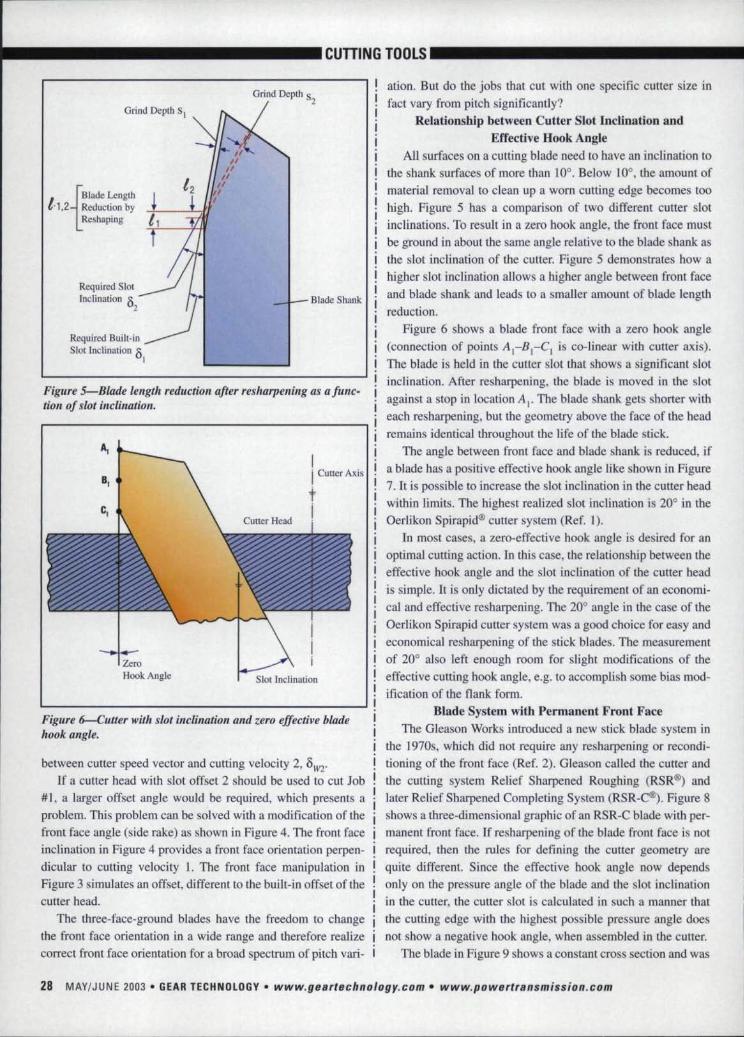
Figure 5-Blade lengtll reduction after resharpening as a fune-tion of slot inclination.
I Cutter Axis
tI
Slot Inclination
Figure6-Cutter with slot inclination and zero effective bladehook angle.
between cutter speed vector and cutting velocity 2, om'If a cutter head with slot offset 2 should be used to cut Job
#1, a larger offset angle would be required, which presents aproblem. This problem can be solved with a modification of thefront face angle (side rake) as shown in Figure 4. The front faceinclination in Figure 4 provides a front face orientation perpen-dicular to cutting velocity 1. The front face manipulation inFigure 3 simulates an offset, different to the built-in offset of thecutter head.
The three-face-ground blades have the freedom to changethe front face orientation in a wide range and therefore realizecorrect front face orientation for a broad spectrum of pitch vari-
-------
ation. But do the jobs that cut with one specific cutter size infact vary from pitch significantly?
Relationship between Cutter Slot [ndinationandEffective Hook Angle
All surfaces on a cutting blade need to have an inclination tothe shank surfaces of more than 10°. Below 10°, the amount ofmaterial removal to clean up a worn cutting edge becomes toohigh. Figure 5 has a comparison of two different cutter slotinclinations. To result in a zero hook angle, the front face mustbe ground in about the same angle relative to the blade shank asthe slot inclination of the cutter. Figure 5 demonstrates how ahigher slot inclination allows a higher angle between front face,and blade shank and leads to a smaller amount of blade lengthreduction.
Figure 6 shows a blade front face with a zero hook angle(connection of points AI-BI-CI is co-linear with cutter axis).The blade is held in the cutter slot that shows a significant slotinclination. After resharpening, the blade is moved in the slotagainst a stop in location A I. •. The blade shank gets shorter witheach resharpening, but the geometry above the face of the headremains identical throughout the life of the blade stick.
The angle between front face and blade shank is reduced, ifa blade has a positive effective hook angle Like shown in Figure7. It is possible to increase the slot inclination in the cutter headwithin limits ..The highest realized slot inclination is 20° in theOerlikon Spirapid® cutter system (Ref. 1).
In most cases, a zero-effective hook angle is desired for anoptimal cutting action. In this case, the relationship between theeffective hook angle and the slot inclination of the cutter headis simple. It is only dictated by the requirement of an economi-cal and effective resharpening. The 20" angle in the case of theOerlikon Spirapid cutter system was a good choice for easy andeconomical resharpening of the stick blades ..The measurementof 20° also left enough room for slight modifications of theeffective cutting hook angle, e.g. to accomplish some bias mod-ification of the flank form.
Blade System with Permanent Front FaceThe Gleason Works introduced a new stick blade system in
the I970s, which did not require any resharpening or recondi-tioning of the front face (Ref. 2). Gleason called the cutter andthe cutting system Relief Sharpened Roughing (RSR@)andlater Relief Sharpened Completing System (RSR-C®). Figure 8shows a three-dimensional graphic of an RSR-C blade with per-manent front face. If resharpening of the blade front face is notrequired, then the rules for defining the cutter geometry arequite different. Since the effective hook angle now dependsonly on the pressure angle of the blade and the slot inclinationin the cutter.the cutter slot is calculated in such a manner thatthe cutting edge with the highest possible pressure angle doesnot show a negative hook angle, when assembled in the cutter.
The blade in Figure 9 shows a constant cross section and was
28, MAY/JUNE 2003 • GEAR iEC'lmOLOGV • www ..geartech.no.logy.com. www.powertransmission.com

•••••• _ CUTTIING TOOLS 11•••• _
the next developmental! step that converted the friction seatingof the blades 1n the cutter in a positive form seating condition.Those blades are called PENTAC® because of their pentagon-shaped cross section (Ref. 3).
The variations of the hook angles from job to job caused bydifferent blade pressure angles have only a very small geornet-rical!influence on the generated flank surface in the single indexface m:illing process. Those first order influences are compen-sated by a pressure angle correction.
To.use the permanent-front-face blade system for the contin-uous face hobbing method causes two additional problems (Ref.4). The effective side rake angle (first problem) might vary fromjob to job (discussed in Figures 3 and 4) caused by the differentoffset angles Ow The side rake problem can be solved with thebIade in Figure 8 by defining a cutter slot offset that is exactlyin the center ofall jobs expected for the particular cutter; Thismeans that a study of the different jobs cut with previous sys-tems can tell very accurately what the average offset angle Owfor a new cutter system should be and what the maximallyaccruing side rake deviations for the extreme jobs are. It istherefore possible 1.0 find an optimal slot position for eachdesigned cutter with less than 2° variation of the effective siderake angle.
The second problem is the influence of the effective hook ofthe cutting edge on the generated flank surface. This influenceis a flank twisting (bias effect). A flank twisting changes thedirection of the path of contact and therefore causes a differentorientation of the contact pattern, but also influences the motiongraph amplitude significantly. In case of the three-Sided-groundblades. it was possible to control. the hook angle of the cuttingedge such that it is always zero (or a predetermined desiredangle). The following sections will explain the flank deviationeffect by hook angle change analytically and present an inter-esting mathematical solution for this problem.
Analysis of the Geometric Effects to the Flank Form byContrelllng tbeFmnt Face Orientation
The publications of Kotthaus (Refs. 1 and 5) teach that tomaintain a sufficient side rake angle,especially to control theflank.surface twist, the front face has to be variable in two angu-lar directions, the side rake angle and the hook angle. The effec-tive hook angle is the inclination around the normal cutterradius (Figure 10) between the cutting edge and the cutter headaxis (Figure 7). The blade in Figure 7 is oriented such that therelative cutting velocity vector lies :in the presentation plane.The effective hook angle is a function of the front face orienta-lion with respect to the blade shank •.as well as the angle of theblade slot in the cutter head (built-in hook angle) and the pres-sure angle of the cutting edge.
A change of the blade pressure angle has a direct influenceonto the pressure angle of the manufactured tooth flank. Achange of the hook angle in a face hobbing cutter blade caus-
GEARBurnishing. •.. from the Source:
Remove nicks, burrs, heat treat scale800 Improve gesr tooth surf8CB.
09IIr 30 J&lI'I ago. er 1taIr1IInI: danloped the gearbumlaIllJIg 1'fOC"S'. Pot your tna! In the .pt!Oplowho InYontO<!the PrQ0800.
MACIw. FEAJI8a IHCWDl:• ~ullVautomated Il.'{$tems.• H~h speed machines.. Potentec Oeroc
OscHlafion System.• Automatic sphsrlcol
p<>sIllonlng.• TrI~va,labledie design.. HOlilontol Of vernecr axis
rnocrmas.- VO~.. ty ot gea. type s.
For additional inionnation 011 li.I!IIcBurnfshlog rmd/or funct!onal.im(
Lnspectlpn: visit our WItlls1rlt at:WWW:frwgears.com
Heartland1205 36th A~ Ww!
Alodndfbl. MN S630B U S IIIPh l320l162-8182... (J2017!l2.!12!10
E·ri'ItI1.lfWONlfIoOi"*"-aIp.'IXI'I'I
GROUND GEARS- ren or ren lhousan,d i
For small to medium quantities of spurs or helicals that have tomeet close-tolerance AGMA or DIN specs, our Relshauer grindersand M&M gear analysis systems are the perfect combination.
For Long runs, we offer the unique Liebherr CBN grindingprocess with full SPC quality control and documentation.
So whether your needs are for ten or tens of thousands, weinvite you to join the growing list of INSCO customers who rely onus for consistent quality, reasonable costs, and reliable delivery.
PHI)NE:978~448~6368FAX:978-448~51'55
_ WEB:lnscecnrp.cnnrnsco 412 Main St~..eet: Groton. Massachusetts 01450RPOIlATION
ISII 90011 IRegistered
www.p,owe'I',rfa.n'smission.c,om. www.getUlechnology.com • GEAR tECHNOLOGY • MAY/JUNE 2003 29

_------------CUTTIINGiTOOlS-------------!cutter Axis
~I
Figure'" Cutter with slot inclination and positiveeffectiJ!eblade hook angle,
BladeShank
Figure 8-RSR'-C stick blade witl:permauent front face and Tee-tangUJIUCTOSS section.
es a flank twist and a change in profile crowning and pressureangle.
Figure 10 shows a blade with the Points A, Band C along acutting edge that has a positive hook angle. The figure also
shows acuning edge without any hook angle (Points AI' B, andC,). The epicyclical path generated by A is different than the
one generated by A [' The curve associated with A I has a simi-tar, but not identical, shape to the one generated by A. Thetwo
crowning as a rather complex. flank form modification,
The blade systems that allow a change of the hook angle use
'this freedom for flank form and contact movement (adjustabili-ty) optimizations. Studying the literature shows that the inven-
tor of those systems found it physically impossible to allow the
same optimizations byavoiditng the individually controlledfront face. All attempts during the past 30 years to' develop a
permanent front. face cutter system with the same freedoms of
the one with front-face-ground blades failed.New SPIROFORMTM Cutter and Blade System
A~ interesting technical challenge was the attempt to devel-
op a cutter and blade system that allows al1 the freedoms of thethree-face-sharpened blade, yet using a blade that is shaped and
sharpened on the two ide relief surfaces only.Finally, a discovery was made that relates the epicycloids,
generated by different hook and side rake angles ..The idea is to
find the radial location of one point along the cutting edge of agiven blade that lies on the same epicycloid, generated by a
blade with different hook and side rake angle, It is assumed thatthe given blade consists of a permanent front face, no hook
angle and a side rake that is constant along the shank. The hookangle of this system is created by an inclination of the slot in the
cutter head.
Figure 11 shows the two different blade types with the roll
circle-base circle kinematic "attached" to the front-face-sharp-ened blade.
The Points Band B[ of the two blade types are identical(Figure 10). The problem to solve is to find the locations of the
Points At and Ct. along the existing front 'face of the simplifiedblade. The geographic height of the blade, with respect to thecutter head front face. remains constant.
To find the location of Point A ['the epicyclical kinematicswith roll circle and base circle are rotated clockwise.until A con-
tacts the front face of the new blade ..This is the location of A l'
The movement from A to A[ requires a rosatioa around the rollcircle center, superimposed 'by a rotation around the center of
the base circle. The relationships for the solution of this prob-lem are shown in Figure 6 and expressed by the following for-
mulas:
(1)
or:
So sin (-4lo-j + 3..,)+ Roo ° sin (0..,)",S' sin (-¢lo- j + 3",+ !Pit) +RBo sin (0", + CPHwk + CPt') (2)
curves are inclined and shined. relative to each other in z-direc- where:
tion, That means the spiral angle of curve A decreases relative Rb(jx' ..to A r The opposite happens for curve B relative to B I.
Thecoaclusion of 'Ihe last paragraph is that the hook angle Rblx".
causes a positive flank twist. between heel and toe. This, togeth-er with the already mentioned change in profile, represents EXOx ...
x-Componeni of Cutter Radius Vector(Blade without Hook)x-Component of Cutter Radius Vector
(Blade with Hook, rotated into zero Hook Plane)x-Component of Vector from Machine Center to
301 MAY/JUNE 2003 • IGEAR IECHN:IJ,lIJGY • www.geartechrro.logy.com " www.powerlra.nsmiSSio.n'.com

I-~~~~-~-~-- --- ------------------~~~~~~~~~---------------------------
.-- --- CUTTIIN'GTOOLS, _
Cutter Center (Blade without Hook)EX3x'" x-Componem of Vector from Machine Center to
Cutter Center (Blade with Hook, rotated intozero Book Plane)
s...'clio'"j ...'0",...Roo'"'IP" ...RB• ..
Radial Distance (Scalar of EXfu)Cutter Phase AngleSwivel AngleOffset. Angle (Face Bobbing)Scalar Cutter Radius (without Hook)Rotation of Cutter Center around Base CircleScalar Cutter Radiu (willi Hook)
<PHook"" Angle between R.8 and RBO
<!le'" Rotation of Blade with Hook Angle aroundRoll Circle (Cutter Center)
Between 'P'", and 'Pc is the following relation hlp:
where:
l.gMuut;ng g~ar' , •
lOlllltr ••.
Number of Teeth 'Generating 'GearNumber of Starts Cutter
Wanted i 'P". out of formula (2). The mathematical olutionis conducted w,ith an iteration algorithm. The difference'between AI and A2 i.s!l. !l.is calculated as shown:
!lis the displacement of the normal radiu (along z-axis) ofpoint Az to come to point A I that cuts the arneepicycloid aspoint A. The epicycloid cut by AI wiU differ [Q some extentfrom the de ired one, cut by A. The hown approach i thephysically closes I. possible approximation, that infinitesimallyobserved still repre ents a mathematically precise solution. Inpractice, it causes difference over the entire Hank surface ofonly a few microns and therefore can be neglected.
The analog scheme is applied to find point CI (Figure.7),o.rotation of the epicyc!ical kinematic in counterclockwise direc-tion brings C (Figure 7) to the front face of (he new blade.
According to the above shown solution. any desired numberof points along the cutting edge with one particular book anglecan be converted into a point on a cutting edge without hookangle 0, a:ny other chosen hook angle.
Depending on the mathematical function of the new cuttingledge (circle, ellip e or higher order). three, five or more pointscan be tran formed from the original tothe new cutting edge.Three points, one on the tip, one in the center and one on theend of the cutting edge, deliver a sufficient definition of the cut-ting edge function to capture lite characteristics of the differentfront face hook angles.
(3)
Figure .9-Pentac stick blade with perma.nentfront face ,andpentago".shaped cress section,
(4) I
Normal RadiusIB=~.IB.' Il,.. . .... A'e, -, -- A
Il I,.B" -,. C
zI -I f'ig.ure J,(J-RelatUmsllip ,between' hook ,angle and IcycloidalpathI (If diffeumt .blade poi"ts.
The possibility to influence the blade spacing in the cutterhead by grinding the front face of either inside or outside bladefurther back results in a tooth thiekne s or slot width change.The SP[ROFORM blades call. account for that feature, too. Atooth thickness adjustment is done by splitting the requiredarneunt and, for example, inereasing the radius of the outerblade cutting edge and decr-easing the cutting edge radiu of theinner blade by half the amount each.
SummaryA method was found to, convert a. side relief and front-face-
sharpened blade, held in a face hob cutter head into a blade thathas a permanent front face and is profile shaped or re-sharpened
www ..pow,e.fuansm.iss.ion' ..com. www.gesrtechn%gy;,com • ,GEA!RnCHN'()LOG,V • MAV/JUNE 2003 311
_-------------CUTTIIN,GTODlS-------------
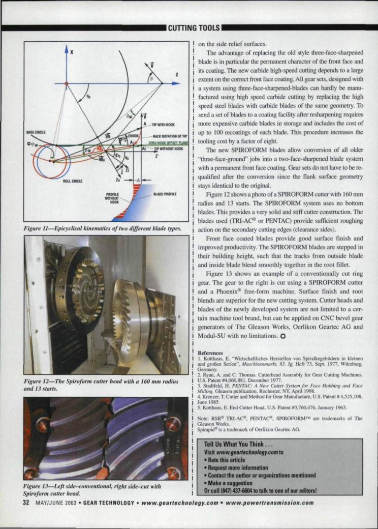
Figtl"'/! ll-Epicyclical kinematics '(J/ two diffenllt blade types.
Figure 12-Tlle Sp.ir%rm cutter head witt: a 160 mm radiusand 13 starts.
on Lite side relief surfaces.The advantage of replacing the old style three-face-sharpened
blade i in particular the permanent character of the front face andits coating. The new carbide high-speed cutting depends to a largeextent on the correct fronl face coating. AU gear sets, designed witha system using three-face- harpened-blades can hardly be manu-factured using high peed carbide cutting by replacing the highspeed steel blades with carbide blades of the same geometry. Tosend a set of blades to a coating facility after resharpening requiresmore expensive carbide blades in torage and includes the cost ofup 10 J 00 recoadngs of each blade. Thi. procedure increases the
tooling co Iby a factor of eight.The new SPlROFORM blades allow conversion of all older
"three-face-ground" jobs. into a two-face-sharpened blade systemwith a permanent front face coating. Gear sets do not have to bere-qualified after d1e conversion inee the flank surface geometrytays identical to the original.
Figure 12show a photo of a SPIROFORM cutter with 1.60nunradius and 13 starts. The SP[ROFORM system 111 es no bottomblades. This provides, a very solid and stiff cutler coastruction Theblades used (TRJ-A ® or PENTA:C) provide sufficient roughingaction onthe secondary cutting edges (clearance sides).
rent face coated blade provide good surface finish andimproved productivity. The SPlROFORM blades are stepped intheir building height. uch that the tracks from outside bladeand in ide blade blend mootWy together in the root fillet,
Figure J 3 shows an example of a conventionally cut ringgear. The gear to the right is cui. using a SPIROFORM cutterand a Phoenix" free-form machine. Surface finish and rootblend are superior for the new cutting sy tern. Cutter heads andblades of the newly developed system are not limited to a cer-tain machine tool brand, but can be applied on CNC bevel geargenerators of The Gleason Works, Oerlikon Geartee A:G andModul-SU with no limitations. 0
R·derencesI. Konhau . E. MWutsch!dllichcs Herstellen von Spiralkegelrddern in kleinenlind gro/3en Seriell", MaschinenmQrJa. 83. Jg. Hefl 13. Sepl. 1977. Wiinb!U8.Germany.2. Ryan, A. and C. Thomas. Cunerhead Assembly for Gear Cutting Machines.U.S. Patent #4.060,881. December 1977.3. Stadtfeld, H. PENTAC: .Ii New Cutter Sy.fll'm for Face Hobbing and FaceMillin.g. Gleason publication, Rochester. NY. April 1998.4,Krenzer, T. Cutter and Method for Gear Manufacture, U.S. Patent 14,525.1 Og,June 198:5,5. Kouhaus, :E .. End Cutter Head, U.S. Patent 13,760.476. January 1%3.
ore: RSRGII TRY-Ace. PENTAC'I. SPIIROFORMTW nee trademarks of TheGleason Works.Spirapid~ is a trademark of Oerlikon Geartec AG.
Tell Us What You Think ...Visit www.• IIltfIChnology.cDlflto• RIle this article• Request more infonnation• Contact die author or organizltions mentioned• Mike I suggestionOr c81118471437-1i604 to tllk 10 ona of OUt editors!
Figure 13-LeJt side-conventiorlal, right slde~cut williSpir%rm cutter head.32 MAY/JUNE 2003 • IGEAIRIECiIlN:·lIl0GV • www.gea,.teclmology ..com • www.p,ower,ransmissio.n.com
Related Documents