a) b) Fig. 1 Structure (a) electric equivalent (b) diagram explaining the manufacturing and measurement –0 structures

Welcome message from author
This document is posted to help you gain knowledge. Please leave a comment to let me know what you think about it! Share it to your friends and learn new things together.
Transcript
a)
b)
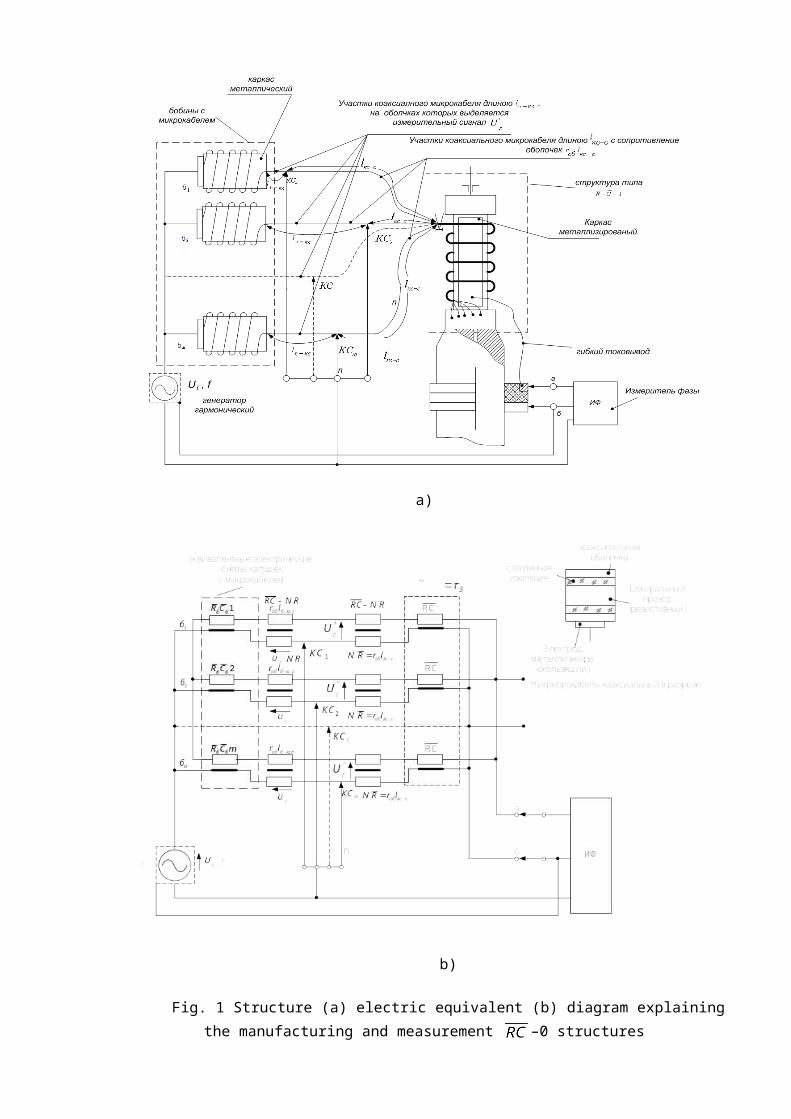
Fig. 1 Structure (a) electric equivalent (b) diagram explaining the manufacturing and measurement –0 structures
a)
b)
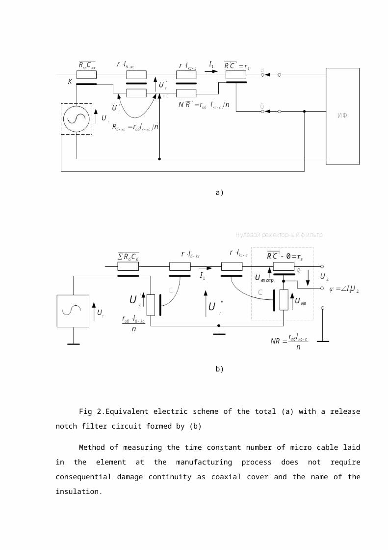
Fig 2.Equivalent electric scheme of the total (a) with a release notch filter circuit formed by (b)
Method of measuring the time constant number of micro cable laid in the element at the
manufacturing process does not require consequential damage continuity as coaxial cover and the name
of the insulation.
Errors do not exceed hundredths or even thousandths of a percent, regardless of the time
constant.
The basis of this method include fusion properties of the zero (notch) filter at the resonant
frequency [6] -0 - length of the line structure as a distributed-constant on the open end of the filter.
Here the resonance frequency of the filter output voltage vector - 0 - structure is in anti-phase
with the current vector at the filter input, and the time constant -0- structure resonant
frequency filter connected unambiguous relationship: .
In fig 1, 2 and 3 are shown diagrams illustrating the principle of indirect measurement of the
time constant of the set value . The time constant of the structure during its manufacture is
continuously measured by measuring the phase shift between , the vector value that flows in a
specific area micro cable shell indicated in Figure 1 by , and the vector of the output voltage
being produced - at the end of an open structure. Resistance micro cable said shell portion , Fig.
1b indicated by NR, is the resistance of the notch filter and manufactured in cooperation with - the
structure of the virtual image of the zero notch filter (Fig. 2b).
As for measuring the signal structure used by the voltage drops on the other shell portion micro
cable, Fig. 1 and the voltage across it (Fig. 1 b and 2 a, b).
Using as a measuring signal voltage that occurs on the shell micro cable file allows the
virtual measuring signal input of the filter without destroying the continuity of the coaxial micro cable
coating and insulation, thereby providing the same phase shift of the voltage vectors at the input of the
current structure . (Fig. 2) . We will demonstrate this.
Conclusion
Considered in the indirect method of measurement of electrical parameters, such as time
constants of the coaxial structures micro wires is original in its meaning in the decision. It provides
high accuracy measurement time constant - determines the value of the phase shift of the signal
regardless of the value of constant, can provide high performance manufacturing structures, regardless
of the number of resistive coaxial micro cable of them simultaneously made structure.
Related Documents


