TRANSLATION OF THE ORIGINAL OPERATING INSTRUCTIONS IMPORTANT READ CAREFULLY BEFORE USE KEEP SAFE TO CONSULT AT A LATER DATE 20-18-4010, 20-18-4011 MY20B04 - 2 • 1.0 • 2. October 2019 E-Rush Evo AM1, E-Rush Evo AM2 1 2

Welcome message from author
This document is posted to help you gain knowledge. Please leave a comment to let me know what you think about it! Share it to your friends and learn new things together.
Transcript

TRANSLATION OF THE ORIGINAL OPERATING INSTRUCTIONS
IMPORTANTREAD CAREFULLY BEFORE USE
KEEP SAFE TO CONSULT AT A LATER DATE
20-18-4010 , 20 -18 -4011
MY20B04 - 2 • 1 .0 • 2 . Oc tober 2019
E -Rush Evo AM1, E -Rush Ev o AM2
1
2
Contents
Contents1 About these operating instructions 51.1 Manufacturer 51.2 Serial number and model 51.3 Identifying the operating instructions 51.4 Subject to change 51.5 Language 51.6 Laws, standards and directives 61.7 For your information 61.7.1 Warnings 61.7.2 Markups 61.8 Nameplate 72 Safety 82.1 General warnings 82.2 Toxic substances 92.3 Requirements for the rider 112.4 Vulnerable groups 112.5 Personal protective equipment 112.6 Safety markings and safety instructions 112.7 Emergency 112.7.1 What to do in an emergency 112.7.2 First aid treatment 112.7.3 Fighting fire 122.7.4 Leaking fluids 122.7.4.1 Brake fluid 122.7.4.2 Oils and lubricants from the fork 122.7.4.3 Oils and lubricants from the rear frame
damper 123 Overview 133.1 Description 143.1.1 Wheel and suspension 143.1.1.1 Valve 143.1.1.2 Rigid fork 143.1.1.3 Suspension fork 143.1.1.4 Steel suspension fork 153.1.1.5 Air suspension fork 153.1.1.6 Structure of the FOX rear frame
damper 163.1.1.7 Structure of the Suntour rear frame
damper 163.1.2 Brake system 173.1.2.1 Rim brake 173.1.2.2 Disc brake 173.1.2.3 Back-pedal brake 173.1.3 Electric drive system 183.1.4 Rechargeable battery 183.1.4.1 Powercore battery 193.1.4.2 Range 193.1.5 Riding light 193.1.6 Display 193.2 Proper use 20
3.3 Improper use 213.4 Technical data 223.4.1 Pedelec 223.4.2 Sachs RS motor 223.4.3 Powercore battery 223.4.4 Display 14d 223.4.5 Emissions 223.4.6 Tightening torque 223.5 Description of controls and screens 233.5.1 Battery on-screen indicators 233.5.1.1 Screen 233.5.1.2 Speed 233.5.1.3 Level of assistance 243.5.1.4 Journey information 243.5.1.5 Battery level indicator 243.6 Environmental requirements 254 Transporting and storing 274.1 Physical transport characteristics 274.1.1 Dimensions during transportation 274.1.2 Transport weight 274.1.3 Designated handles/lifting points 274.2 Transporting 274.2.1 Transporting the battery 284.2.2 Shipping the battery 284.2.3 Using the brake transport securing
system 284.3 Storing 284.3.1 Break in operation 294.3.1.1 Preparing a break in operation 294.3.1.2 Taking out of operation 295 Assembly 305.1 Required tools 305.2 Unpacking 305.2.1 Scope of delivery 305.3 Commissioning 315.3.1 Checking the battery 315.3.2 Installing the wheel in the Suntour fork 315.3.2.1 Screw-on axle (15 mm) 315.3.2.2 Screw-on axle (20 mm) 325.3.2.3 Quick release axle 325.3.2.4 Quick release 345.3.3 Installing the wheel in the FOX fork 355.3.3.1 Quick release (15 mm) 355.3.3.2 Kabolt axle 365.3.4 Checking the stem and handlebars 365.3.4.1 Checking connections 365.3.4.2 Firm hold 365.3.4.3 Checking the headset backlash 365.4 Pedelec sale 36
MY20B04 - 2_1.0_02.10.2019 2

Contents
6 Operation 376.1 Risks and hazards 376.1.1 Personal protective equipment 386.2 Tips for a greater range 386.3 Error messages 396.3.1 Error message display 396.4 Instruction and customer service 406.5 Adjusting the pedelec 406.5.1 Adjusting the saddle 406.5.1.1 Adjusting the saddle tilt 406.5.1.2 Determining the seat height 406.5.1.3 Adjusting the seat height with quick
release 416.5.1.4 Height-adjustable seat post 416.5.1.5 Adjusting the seat position 416.5.2 Adjusting the handlebars 426.5.3 Adjusting the stem 426.5.3.1 Adjusting the height of the handlebars 426.5.3.2 Adjusting the quick release clamping
force 436.5.4 Setting the brake 436.5.4.1 Setting the grip distance on a
Magura HS33 brake lever 436.5.4.3 Setting the grip distance on a
Magura disc brake lever 446.5.4.4 Setting the pressure point on a
Magura brake lever 446.5.5 Retracting the brake linings 456.5.6 Adjusting Suntour fork 456.5.6.1 Adjusting the negative deflection 456.5.6.2 Adjusting the steel suspension fork
negative deflection 456.5.6.3 Adjusting the air suspension fork
negative deflection 456.5.6.4 Adjusting the air suspension fork
rebound 466.5.7 Adjusting the FOX fork 466.5.7.1 Adjusting the negative deflection 476.5.7.2 Adjusting the rebound 486.5.8 Setting the Suntour rear frame damper 486.5.8.1 Adjusting the negative deflection 486.5.8.2 Adjusting the rebound 486.5.8.3 Setting the compression 496.5.9 Setting the FOX rear frame damper 496.5.9.1 Adjusting the negative deflection 496.5.9.2 Adjusting the rebound 506.6 Accessories 516.6.1 Child seat 516.6.2 Bicycle trailers 526.6.3 Pannier rack 526.7 Before each ride 536.8 Check list before each ride 53
6.9 Using the kickstand 546.9.1 Raising the kickstand 546.9.1.1 Parking the pedelec 546.10 Using the pannier rack 546.11 Rechargeable battery 556.11.1 Removing the battery 556.11.2 Inserting the battery 556.11.3 Charging the battery 566.12 Electric drive system 576.12.1 Switching on the electric drive system 576.12.2 Switching off the drive system 576.13 Control panel with display 586.13.1 Using the driving light 586.13.2 Using the push assist system 586.13.3 Selecting the levels of assistance 586.13.4 Changing the kilometre display unit 586.13.5 Switching the journey information 586.13.5.1 Deleting the journey distance 586.14 Brake 596.14.1 Using the brake lever 606.14.2 Using the back-pedal brake 606.15 Suspension and damping 606.15.1 Adjusting the compression in the
Fox fork 606.15.2 Adjusting the compression in the
Fox damper 606.15.3 Adjusting the compression in the
Suntour fork 616.15.4 Adjusting the compression in a
Suntour damper 616.15.5 Adjusting the rebound in a
RockShox damper 626.15.6 Adjusting the compression in a
RockShox damper 626.16 Gear shift 626.16.1 Selecting gears 636.16.2 Using the hub gear 637 Cleaning and servicing 647.1 Cleaning after each ride 647.1.1 Cleaning the suspension fork 647.1.2 Cleaning the rear frame damper 647.1.3 Cleaning the pedals 647.2 Basic cleaning 657.2.1 Cleaning the frame 657.2.2 Cleaning the stem 657.2.3 Cleaning the wheel 657.2.4 Cleaning the drive elements 657.2.5 Cleaning the rear frame damper 657.2.6 Cleaning the chain 667.2.7 Cleaning the battery 667.2.8 Cleaning the display 667.2.9 Cleaning the drive unit 667.2.10 Cleaning the brake 67
MY20B04 - 2_1.0_02.10.2019 3

Contents
7.3 Servicing 677.3.1 Servicing the frame 677.3.2 Servicing the stem 677.3.3 Servicing the fork 677.3.4 Servicing the drive elements 677.3.5 Servicing the pedals 677.3.6 Servicing the chain 677.3.7 Servicing the drive elements 677.4 Maintenance 687.4.1 Wheel 687.4.1.1 Checking the tyres 687.4.1.2 Checking the rims 687.4.1.3 Checking and adjusting the tyre
pressure – Dunlop valve 687.4.1.4 Checking and adjusting the tyre
pressure – presta valve 697.4.1.5 Checking and adjusting the tyre
pressure – Schrader valve 697.4.2 Brake system 697.4.3 Checking the brake linings for wear 697.4.4 Checking the pressure point 697.4.5 Checking the brake discs for wear 707.4.6 Electrical cables and brake cables 707.4.7 Gear shift 707.4.8 Stem 707.4.9 USB port 707.4.10 Checking the belt and chain tension 708 Maintenance 718.1 Axle with quick release 728.1.1 Checking the quick release 728.2 Adjusting the gear shift 728.2.1 Cable-operated gear shift, single-cable 738.2.2 Cable-operated gear shift, dual-cable 738.2.3 Cable-operated twist grip, dual-cable 739 Troubleshooting, fault clearance
and repair 749.1 Troubleshooting and fault clearance 749.1.1 The drive system or display do not
start up 749.1.2 Error messages 749.2 Assistance function 759.3 Rechargeable battery 769.4 Lighting 779.5 Miscellaneous 779.6 Repair 789.6.1 Use original parts and lubricants only 789.6.2 Replacing the lighting 789.6.3 Adjusting the headlight 789.6.4 Tyre clearance check 78
10 Recycling and disposal 7911 Documents 8011.1 Parts list 8011.2 Assembly report 8111.3 Maintenance log 8312 Keyword index 8614 Glossary 8714.1 Abbreviations 8914.2 Simplified terms 89I. Translation of the original
EU Declaration of Conformity 90
MY20B04 - 2_1.0_02.10.2019 4

About these operating instructions
1 About these operating instructions
Thank you for your trust!
BULLS pedelecs are premium quality bicycles. You have made an excellent choice. Your specialist dealer will provide you with guidance and instruction and assemble your product. Your specialist dealer will also be happy to assist you in the future whether you require maintenance, conversion or repair.
You are receiving these operating instructions with your new pedelec. Please take time to become familiar with your new pedelec and follow the tips and suggestions in the operating instructions. They will help you to enjoy your pedelec for a long time to come. We hope you have fun and wish you well on all of your rides!
These operating instructions are mainly designed for the rider or the operator. They aim to ensure that non-professionals can use the pedelec safely.
Download the operating instructions onto your phone at the following link, so that you can use them when you are out riding:
www.bulls.de/service/downloads.
1.1 Manufacturer The pedelec manufacturer is:
ZEG Zweirad-Einkaufs-Genossenschaft eGLongericher Straße 250739 Köln, Germany
Tel.: +49 221 17959 0 Fax: +49 221 17959 31 Email: [email protected] Website: www.zeg.de
1.2 Serial number and modelThese operating instructions are an integral part of pedelecs with the following serial numbers:
1.3 Identifying the operating instructions
You will find the operating instructions identification number at the bottom left-hand side of each page. The identification number consists of the document number, the version number and the release date.
1.4 Subject to change The information contained in these operating instructions are the approved technical specifications at the time of printing. Any significant changes will be included in a new issue of the operating instructions.
You will find any modifications to these operating instructions: www.bulls.de/service/downloads.
1.5 Language The original operating instructions are written in German. A translation is not valid without the original operating instructions.
Notice
These operating instructions are not a substitute for personal instruction by the supplying specialist dealer.
These operating instructions are an integral part of the pedelec. Therefore, if it is re-sold at a later time, they must be handed over to the subsequent owner.
Sections are also designed especially for the specialist dealer. These sections aim to ensure that specialist dealers complete initial assembly and maintenance safely and reliably. The sections for specialist dealers are highlighted in grey and marked with a spanner symbol.
Type Model Pedelec type
20-18-4011 E-Rush Evo AM1 29" City and trekkingbicycle
20-18-4010 E-Rush Evo AM2 29" City and trekkingbicycle
Table 1: Type (serial number), model and pedelec type
Identification number MY20B04 - 2_1.0_02.10.2019
MY20B04 - 2_1.0_02.10.2019 5

About these operating instructions
1.6 Laws, standards and directives These operating instructions comply with the essential requirements specified in:
• Machinery Directive 2006/42/EC• Electromagnetic Compatibility Directive
2014/30/EU• ISO 20607:2018 Safety of machinery –
Instruction handbook – General drafting principles
• EN 15194:2018 Cycles – Electrically power assisted cycles – pedelec bicycles
• EN 11243:2016, Cycles – Luggage carriers for bicycles – Requirements and test methods
• EN ISO 17100:2016-05, Translation Services – Requirements for translation service.
1.7 For your information Different markings are used in these operating instructions to make them easier to read.
1.7.1 Warnings Hazardous situations and actions are marked with warnings. The warnings in these operating instructions are indicated as follows:
1.7.2 MarkupsThe following conventions are used in these operating instructions:
Will lead to serious or even fatal injuries if ignored. High-risk hazard.
May lead to serious or even fatal injuries if ignored. Medium-risk hazard.
May lead to minor or moderate injuries. Low-risk hazard.
Notice
May lead to material damage if ignored.
DANGER!
WARNING!
CAUTION!
Convention Use
Italics Glossary term
Underlined in blue Link
Underlined in grey Cross references
Check marks Requirements
Triangle Instruction for action
1 Instruction for action
Several instructions for action in specified order
Result of the action
SPACED Indicators on the display screen
• Bulleted lists Only applies to pedelecs with this equipment
Other models feature other equipment. A note beneath the heading indicates components which can be used as an alternative.
Table 2: Markups
Instructions for the specialist dealer are highlighted in grey and marked with a spanner symbol. Information for specialist dealers does not require non-professionals to take any action.
MY20B04 - 2_1.0_02.10.2019 6

About these operating instructions
1.8 Nameplate The nameplate is situated on the frame. You will find the precise position of the nameplate in
Figure 2. You will find thirteen pieces of information on the nameplate.
Figure 1: Nameplate, example
ZEG Zweirad-Einkaufs-Genossenschaft eGLongericher Str. 2
50739 Köln, GermanyTyp:
20-16-0001
EN 15194
0,25 kW / 25 km/hzGG 180 kgEPAC 25 kg
BJ 2019 / MJ 2020
nachEPAC
2
3
1
4
5
6
7
8 9
12
13
10
11
No. Designation Description
1 CE marking The manufacturer uses the CE marking to declare that the pedelec complies with applicable requirements.
2 Manufacturer's contact details You can contact the manufacturer at this address. You can find more information in Section 1.1.
3 Serial numberAll pedelec models have an eight-digit serial number, which is used to specify the design model year, the type of pedelec and the version. You can find more information in Section 1.2.
4 Maximum continuous power The maximum continuous power is the maximum power for the electric motor output shaft during 30 minutes.
5 Permitted total weight The permitted total weight is the weight of the fully assembled pedelec with the rider and baggage.
6 Year of manufacture The year of manufacture is the year in which the pedelec was manufactured. The production period is from August 2019 to July 2020.
7 Pedelec type You can find more information in Section 3.2.
8 Safety markings You can find more information in Section 1.7.
9 Disposal instructions You can find more information in Section 10.
10 Area of use You can find more information in Section 3.5.
11 Model year
The model year refers to the first production year that the series-manufactured pedelec was produced in the version and is not always identical with the year of manufacture. The year of manufacture may be before the model year in some cases. If no technical modifications are introduced to the series, production may continue of pedelecs from a previous model year.
12 Weight of the ready-to-ride pedelec The indicated weight for a ready-to-ride pedelec refers to the weight at the time of purchase. The weight of each additional accessory must be added to this weight
13 Shut-off speed Speed reached by the pedelec at the moment when the current has dropped to zero or to the no load current value.
Table 3: Nameplate details
MY20B04 - 2_1.0_02.10.2019 7

Safety
2 Safety
2.1 General warnings
Risk of fire and explosion due to faulty batteryThe safety electronics may fail if the battery is damaged or faulty. The residual voltage can cause a short circuit. The battery may self-ignite and explode.
If the battery becomes deformed or begins to smoke, keep at a safe distance and disconnect the power supply at the socket.Contact the fire service immediately.
Never extinguish a damaged battery with water or allow it to come into contact with water.
If the battery is dropped or struck but shows no signs of external damage, remove it from service and observe it for at least 24 hours.
Batteries with external damage must be removed from service immediately.
Faulty batteries are hazardous goods. Dispose of faulty batteries properly and as quickly as possible.
Store battery in a dry place until disposal. Never store in the vicinity of flammable substances.
Never open or repair the battery.
Only use and charge the battery and accessories if they are in perfect condition.
Electric shock in case of damage
Damaged chargers, cables and plug connectors increase the risk of electric shock.
Check the charger, cable and plug connector before each use. Never use a damaged charger.
WARNING!
CAUTION!
Risk of fire and explosion due to short circuitSmall metal objects may connect the battery's electrical terminals. The battery may self-ignite and explode.
Keep paper clips, screws, coins, keys and other small parts away and do not insert them into the battery.
Risk of fire and explosion due to incorrect charger
Batteries which are recharged with an unsuitable charger may become damaged internally. This may result in fire or an explosion.
Only use batteries approved for the pedelec.
Mark the supplied charger clearly to prevent mix-ups – with the frame number or serial number, for example.
Risk of fire and explosion due to penetration by waterThe battery is only protected from spray water. Penetration by water can cause a short circuit. The battery may self-ignite and explode.
Never immerse the battery in water.
If there is reason to believe that water may have entered into the battery, the battery must be removed from service.
Electric shock caused by penetration by water
If water penetrates into the charger, there is a risk of electric shock.
Never charge the battery outdoors.
CAUTION!
MY20B04 - 2_1.0_02.10.2019 8

Safety
2.2 Toxic substances
Fire caused by overheated charger
The charger heats up when charging the battery. In case of insufficient cooling, this can result in fire or burns to the hands.
Never use the charger on a highly flammable surface (e.g. paper, carpet etc.).
Never cover the charger during the charging process.
Never leave the battery unattended during charging.
Risk of fire and explosion due to high temperatures
Temperatures over 60 °C can also cause liquid to leak from the battery and the battery will become damaged. The battery may self-ignite and explode.
Protect the battery against heat.
Never store next to hot objects.
Never expose the battery to sustained direct sunlight.
Avoid wide temperature fluctuations.
Notice
If you leave a key inserted when riding or transporting the pedelec, it may break off or the locking system may open accidentally.
Remove the key from the battery lock immediately after use.
We recommend that you attach the key to a key ring.
CAUTION!
Brake fluid can be fatal if it is swallowed and penetrates the respiratory system
Brake fluid may leak out after an accident or due to material fatigue. Brake fluid can be fatal if swallowed or inhaled.
First aid treatment
Wear gloves and safety goggles as protective equipment. Keep unprotected persons away.
Remove those affected from the danger area to fresh air. Never leave those affected unattended.
Ensure sufficient ventilation.
Immediately remove clothing items contaminated with brake fluid.
Serious slip hazard due to brake fluid leakage.
Keep away from naked flames, hot surfaces and sources of ignition.
Avoid contact with skin and eyes.
Do not inhale vapours or aerosols.
After inhalation
Take in fresh air. Immediately consult a doctor in case of any discomfort.
After skin contact
Wash affected skin with soap and water and rinse well. Remove contaminated clothing. Consult doctor in the event of pain or discomfort.
After contact with eyes
Rinse eyes under flowing water for at least ten minutes with the lids open; also rinse under lids. Immediately consult a doctor in case of any pain or discomfort.
DANGER!
MY20B04 - 2_1.0_02.10.2019 9

Safety
After swallowing
Rinse out mouth with water. Never induce vomiting! Risk of aspiration!
Place a person lying on their back who is vomiting in a stable recovery position on their side. Seek medical advice immediately.
Environmental protection measures
Never allow brake fluid to flow into the sewage system, surface water or groundwater.
Notify the relevant authorities if fluid penetrates the ground or pollutes water bodies or the sewage system.
Intoxication from suspension oil
Suspension oil in the rear frame damper is toxic to the touch, irritates respiratory tracts and causes cancer, sterility and mutation in germ cells. Never disassemble the rear frame damper.
Never allow suspension oil to come into contact with the skin.
Environmental hazard posed by oil and lubricants from rear frame damper
The rear frame damper contains toxic and environmentally harmful oils and lubricants. Such fluids will contaminate if they enter the sewers or groundwater. Dispose of oils and lubricants which have
leaked from the rear frame damper in an environmentally responsible way in accordance with statutory regulations. Contact your specialist dealer.
WARNING!
CAUTION!
Hazard for the environment due to leaking brake fluid
The brake system contains a toxic, environmentally harmful brake fluid. Such fluids will contaminate if they enter the sewers or groundwater. The brake system must be repaired
immediately if brake fluid leaks out. Contact your specialist dealer.
Dispose of leaking brake fluid in an environmentally responsible way in accordance with statutory regulations. Contact your specialist dealer.
Chemical burns to the skin and eyes caused by faulty batteryLiquids and vapours may leak from damaged or faulty batteries. Excessive temperatures can also cause liquid to leak from the battery and the battery will become damaged. They can irritate the airways and cause burns.
Avoid contact with leaked liquids.
Take in fresh air. Consult doctor in the event of pain or discomfort.
Immediately consult a doctor in case of contact with the eyes or any discomfort.
In case of contact with the skin, rinse off immediately with water.
Ventilate the room well.
Environmental hazard posed by oil and lubricants from the fork
The fork contains toxic, environmentally harmful oils and lubricants. Such fluids will contaminate if they enter the sewers or groundwater. The fork must be repaired immediately if oils
and lubricants are leaking out. Contact your specialist dealer.
Dispose of leaked oils and lubricants in an environmentally responsible way in accordance with statutory regulations. Contact your specialist dealer.
CAUTION!
MY20B04 - 2_1.0_02.10.2019 10

Safety
2.3 Requirements for the rider If there are no legal requirements for riders of electrically power-assisted cycles, we recommend that the rider should be a minimum 15 years of age and have experience with muscle-powered bicycles.
The rider's physical and mental abilities must be adequate to use a muscle-powered pedelec.
2.4 Vulnerable groups You must keep batteries and charger away from children and people with reduced physical, sensory or mental capabilities or lacking in experience and knowledge.
If minors use the pedelec, comprehensive instruction should be provided by or in the presence of the legal guardians. Supervised use should also be scheduled until the pedelec is being used as per these operating instructions.
2.5 Personal protective equipment We recommend that you wear a suitable cycling helmet. We also recommend that you wear sturdy footwear and typical, close-fitting clothing for bicycles.
2.6 Safety markings and safety instructions
The nameplate contains the following safety markings and safety instructions:
2.7 Emergency2.7.1 What to do in an emergency In the event of a hazard or danger in road
traffic, apply the brakes on the pedelec until it comes to a halt. The brake acts as an emergency stop system in such cases.
2.7.2 First aid treatment Consult a doctor immediately in the event of
any pain or discomfort caused by combustion gas or leaking fluids.
After inhalation
Vapours may emit if the battery is damaged or used improperly The vapours may cause respiratory tract irritation.
Get into fresh air.
Consult doctor in the event of pain or discomfort.
Symbol Explanation
General warning
Adhere to the instructions for use
Table 4: Meaning of safety markings
Symbol Explanation
Read the instructions
Separate collection of electrical and electronic devices
Separate collection of ordinary and rechargeable batteries
Do not throw into a fire
Do not immerse in liquids
It is forbidden to open any batteries
Device of protection class II
Only suitable for use indoors
Fuse (device fuse)
EU conformity
Recyclable material
MY20B04 - 2_1.0_02.10.2019 11

Safety
After contact with eyes
Rinse eyes with plenty of water for at least 15 minutes. Protect unaffected eye. Seek medical advice immediately.
After skin contact
Remove any solid particles immediately.
Rinse the affected area with plenty of water for at least 15 minutes. Then dab the affected skin gently. Do not rub dry.
Remove contaminated clothing immediately.
Immediately consult a doctor if there is any redness, pain or discomfort.
After swallowing
Drink plenty of milk or water and induce vomiting.
Seek medical advice immediately.
2.7.3 Fighting fire
The safety electronics may fail if the battery is damaged or faulty. The residual voltage can cause a short circuit. The battery may self-ignite and explode.
Keep your distance if the battery becomes deformed or starts to emit smoke.
Evacuate everyone from the immediate area of the fire.
Contact the fire service immediately!
Carefully removed any other batteries if possible.
Evacuate everyone from the immediate area of the fire.
Use Class fire extinguishers to put out the fire.
Never extinguish damaged batteries with water or allow them to come into contact with water.
2.7.4 Leaking fluids
2.7.4.1 Brake fluid
The brake system must be repaired immediately if brake fluid leaks out. Contact your specialist dealer.
Dispose of leaking brake fluid in an environmentally responsible way in accordance with statutory regulations. Contact your specialist dealer.
2.7.4.2 Oils and lubricants from the fork
The brake system must be repaired immediately if brake fluid leaks out. Contact your specialist dealer.
Dispose of leaking brake fluid in an environmentally responsible way in accordance with statutory regulations. Contact your specialist dealer.
2.7.4.3 Oils and lubricants from the rear frame damper
Dispose of oils and lubricants which have leaked from the rear frame damper in an environmentally responsible way in accordance with statutory regulations. Contact your specialist dealer.
Intoxication
Inhaling vapours can cause intoxication.
Stand on the side of the fire where the wind is blowing from.
Use breathing apparatus if possible.
WARNING!
MY20B04 - 2_1.0_02.10.2019 12

MY20B04 - 2_1.0_02.10.2019 13
Operation
3 Overview
Figure 2: Pedelec viewed from the right: E-Rush Evo AM1
1 Front wheel2 Fork3 Handlebars4 Stem5 Frame6 Rear frame damper
7 Seat post8 Saddle9 Rear wheel10 Chain11 Frame number 12 Nameplate and battery (in frame)
1
2
3456
7
8
10 119
1
2
3456
78
10 11 12
9

Overview
3.1 Description3.1.1 Wheel and suspension The pedelec has two wheels: a front wheel and a rear wheel.
Figure 3: Components of the wheel, example of front wheel
1 Tyre2 Rim3 Suspension fork head with setting wheel4 Shock absorber5 Spoke6 Quick release7 Hub8 Valve9 Fork end of the shock absorber
3.1.1.1 Valve
Each wheel has a valve. It is used to fill the tyre with air. There is a valve cap on each valve. The screw-on valve cap keeps out dust and dirt.
The pedelec either has a conventional Dunlop valve, a Presta valve or a Schrader valve.
3.1.1.2 Rigid fork
Rigid forks do not feature suspension. They transfer the used muscle and motor power to the road to optimum effect. Pedelecs with rigid forks consume less energy on steep roads and have a greater range than pedelecs with adjusted suspension.
3.1.1.3 Suspension fork
A suspension fork is based either on a steel spring or air suspension.
Unlike a rigid fork, a suspension fork has two functions which improve floor contact and comfort: suspension and damping. The suspension prevents an impact, such as one caused by a stone lying in the pedelec's path, from being channelled directly into the rider's body via the fork. The impact is absorbed by the suspension system instead. This causes the suspension fork to compress.
Figure 4: Pedelec without suspension (1) and with suspension (2) when riding over an obstacle
After compressing, the suspension fork returns to its original position. If there is a damper, it decelerates movement, preventing the suspension system from springing back in an uncontrolled manner and stopping the fork from vibrating up and down. Dampers which dampen compressive deflection movements, i.e. a compression load, are called compression dampers or compression dashpots.
Dampers which dampen rebound deflection movements, i.e. a rebound load, are called rebound dampers or dashpots.
The compression can be disabled in any suspension fork. A suspension fork will then behave like a rigid fork.
1
24
5
8
7
3
9
6
1 2
MY20B04 - 2_1.0_02.10.2019 14

Overview
3.1.1.4 Steel suspension fork
The stem and handlebars are fastened to the fork steerer (1). The wheel is fastened to the quick release axle (6).
Figure 5: Example showing Suntour fork
Other elements: the setting wheel for negative deflection (9), crown (3), Q-Loc (5), dust seal (4), fork end (7) and stanchion (8).
3.1.1.5 Air suspension fork
The air suspension fork features air suspension and a compression damper plus a rebound damper in some cases.
Figure 6: Example showing Yari fork
You can see the following components in the diagram: Air valve (1), valve cap (2) fork lock (3), quick release (4) and rebound damper adjuster (5) and the assembly groups: Air suspension fork (A), compression damper assembly group (B) and rebound damper assembly group (C)
11
2
3
4
5
6
8
9
7
A
B C
12
3
4
5
AB
C
MY20B04 - 2_1.0_02.10.2019 15

Overview
3.1.1.6 Structure of the FOX rear frame damper
The rear frame damper features air suspension, a compression damper and a rebound damper.
Figure 7: Example showing FOX rear frame damper
1 Guide rod eye2 Air valve3 Setting wheel 4 Lever5 Air chamber6 O-ring
3.1.1.7 Structure of the Suntour rear frame damper
The rear frame damper features air suspension, a compression damper and a rebound damper.
Figure 8: Example showing Suntour rear frame damper
1 Upper eye2.1 Total damper length2.2 SAG3 Lower eye4 O-ring5 Sleeve6 Damper unit7 IFP (internal floating piston)8 Air valve9 Air chamber10 Lockout lever11 Rebound lever
25-30%1
2
4
3
12.2
3
45
6
7 8
9 1011
2.1
MY20B04 - 2_1.0_02.10.2019 16

Overview
3.1.2 Brake system The pedelec's brake system comprises either a hydraulic:
• rim brake on the front and rear wheels• disc brake on the front and rear wheels or • a rim brake on the front and rear wheels and an
additional back-pedal brake.
The mechanical brakes are used as an emergency stop system and bring the pedelec to a halt quickly and safely in the event of an emergency.
3.1.2.1 Rim brake
Figure 9: Rim brake components with details; Magura HS22 used as an example
1 Rear wheel rim brake2 Brake booster3 Brake lining4 Handlebars with brake lever 5 Front wheel rim brake
The rim brake stops the wheel moving when the rider pulls the brake lever, causing two brake linings, positioned opposite one another, to be pressed onto the rims. The hydraulic rim brake features a locking lever.
Figure 10: Rim brake locking lever, closed (1) and open (2)
3.1.2.2 Disc brake
Figure 11: Pedelec brake system with a disc brake – example
1 Brake disc2 Brake calliper with brake linings3 Handlebars with brake lever 4 Front wheel brake disc5 Rear wheel brake disc
On a pedelec with a disc brake, the brake disc is screwed permanently to the wheel hub.
The brake lever is pushed to increase brake pressure. The brake fluid is used to transfer pressure through the brake lines to the cylinders in the brake calliper. The braking force is boosted by a speed reduction and applied to the brake linings. These apply the brake disc mechanically. If the brake lever is pushed, the brake linings are pressed against the brake disc and the wheel movement is decelerated until it comes to a stop.
3.1.2.3 Back-pedal brake
Figure 12: Pedelec brake system with a back-pedal brake – example
1 Rear wheel rim brake2 Handlebars with brake lever 3 Front wheel rim brake 4 Pedal5 Back-pedal brake
The back-pedal brake stops the movement of the rear wheel when the rider pedals in the opposite direction to the direction of travel.
The rim brake locking lever is not marked with any lettering. Only a specialist dealer may set the rim brake locking lever
1
2
34
5
21
1
23
4
5
5
2
3
4
1
MY20B04 - 2_1.0_02.10.2019 17

Overview
3.1.3 Electric drive systemThe pedelec is driven by muscle power applied to the chain drive. The force which is applied by pedalling in the direction of travel drives the front chain wheel. The chain transmits the force onto the rear chain wheel and then onto the rear wheel.
You can ride the pedelec like a normal bike at any time, either by switching off the electric drive system or changing the level of assistance to Off. The same applies when the battery is empty.
Figure 13: Diagram of drive system
1 Direction of travel2 Chain3 Rear chain wheel4 Front chain wheel5 Pedal
The pedelec also has an integrated electric drive system in addition to its drive system propelled by muscle power. The electric drive system is made up of 7 components:
Figure 14: Diagram of electric drive system
1 Headlight2 Display3 Operating element 4 Rechargeable battery5 Rear light6 Motor• A charger designed for the battery.
As soon as the required muscle power from the rider pedalling passes a certain level, the motor is activated gently and assists the pedalling motion of the rider. The motor force is determined by the set level of assistance. The assistance depends on the force applied to the pedals by the rider. Drive system assistance is therefore only activated when the rider pedals. This applies irrespective of the selected level of assistance. The motor switches off automatically as soon as the rider no longer pedals, the temperature is outside the permitted range, there is an overload or the shut-off speed of 25 km/h has been reached. If the speed falls below 25 km/h, the assistance is automatically activated again.
A push assist system can be activated. The push assist system continues to drive the pedelec as long as the rider pushes the plus rocker button on the handlebars. The speed can be a maximum of 6 km/h in this case.
3.1.4 Rechargeable batteryThe rechargeable battery powers the pedelec's drive system. It may only be used with designated compatible drive systems and chargers.
The lithium ion battery has an internal electronic protection circuit, which is specifically designed for the charger and the pedelec. A protection circuit protects the battery against overcharging, deep discharge, overcurrent, short circuits and operation outside the permitted temperature range. In the event of a hazard, a protective circuit switches the battery off automatically.
The battery's service life can be extended if it is well maintained and stored at correct temperature. The charging capacity will decrease with age, even if the battery is maintained properly. If the operating time is severely shortened after charging, this is a sign that battery has reached the end of its useful life.
5
2
3
4
1
B
3 1
2
4
5
MY20B04 - 2_1.0_02.10.2019 18

Overview
Contact your dealer if you are unable to recharge the battery or it is damaged.
3.1.4.1 Powercore battery
Figure 15: Powercore battery details
1 Battery level indicator2 On-Off switch (battery)3 Label4 Port for charger plug 5 Discharge port
Battery level indicator
The five green LEDs on the battery level indicator show the charge level when the battery is switched on. Each LED represents 20% of the charge level. The charge level for the activated battery is also shown on the display screen.
If the battery level falls below 5%, all the LEDs on the operating status and battery level indicator will go out. However, the battery level is still shown on the display screen.
3.1.4.2 Range
The range is influenced by many factors, such as:
• level of assistance: the higher the selected level of assistance, the lower the range
• gear switching habits • tyre type • tyre pressure • the age, condition and charge level of the battery • route profile (slopes) and route quality (road
surface)• weather conditions (e.g. opposing winds, ambient
temperature, etc.) • e-bike weight and• load
3.1.5 Riding lightWhen the riding light is activated, the headlight and the rear light are switched on.
3.1.6 DisplayThe display controls the drive system and shows the journey data. The pedelec's battery powers the display screen when a sufficiently charged battery is inserted into the pedelec and the drive system is switched on.
The operating element consists of an LCD display, 2 rocker switches and 3 buttons.
Figure 16: Display details
Ideal storage temperature 22 °C - 26 °C
Table 5: Rechargeable battery technical data
12
3
4
5
Storage temperature 5 °C - 25 °C
Charging ambient temperature -10 °C - +60 °C
Table 6: Display technical data
Use1 Plus rocker button2 On-Off button3 Light button4 Settings button5 Minus rocker button6 Screen display
Table 7: Display overview
1
2
1
3
2
4 56
MY20B04 - 2_1.0_02.10.2019 19

Overview
3.2 Proper use The pedelec must only be used in perfect, fully functional condition. National requirements may apply to the pedelec which the standard equipment may not meet. For riding on public roads, some special regulations apply in relation to the riding light, reflectors and other components.
The general laws and the regulations for the prevention of accidents and environmental
protection in the respective country of use must be adhered to. All check lists and instructions for actions in these operating instructions met. Approved accessories can be installed by specialist staff.
Each pedelec is assigned a pedelec type, which determines its proper use, function and area of use.
City and trekking bicycles
Child's bicycles/bicycles for young adults
Mountain bikes Racing bicycle Cargo bike Folding bicycle
City and trekking bicycles are designed for daily, comfortable use. They are suita-ble for riding on public roads.
The legal guardians of minor riders must read and understand these operating instructions before commissioning.
The contents of these operating instruc-tions must be com-municated to the riders in an age-appropriate manner.
The cycles for chil-dren and young adults are suitable for riding on public roads. The size of the pedelec must be checked regularly for orthopaedic reasons.
A check must be made at least every three months to make sure that the maxi-mum permitted total weight is being observed.
Mountain bikes are designed for sporting use. The design char-acteristics include a short wheelbase, a sitting position with the rider inclined towards the front, and a brake requiring low actuation force.
A mountain bike is a piece of sporting equipment. It requires an adaptation period as well as physical fit-ness. Use requires the appropriate train-ing; in particular rid-ing in bends and braking should be practised.
The strain on the rider, in particular the hands and wrists, arms, shoulders, neck and back, is accordingly high. Inexperienced riders tend to brake exces-sively and lose con-trol as a result.
A racing bicycle is designed for fast rides on roads and paths with a good, undamaged road sur-face.
A racing bicycle is a piece of sporting equipment and not a means of transport. A racing bicycle is char-acterised by its light-weight structure and a design which is stripped to the mini-mum parts required for riding.
The frame geometry and the layout of the operating elements are designed in such a way that the bicy-cle can be ridden at high speeds. The frame design requires practice to ensure the ride is able to ride slowly, apply the brakes and get on and off the bike safely.
The sitting position is athletic. The strain on the rider, in particular the hands and wrists, arms, shoulders, neck and back, is accordingly high. The sitting position there-fore requires physi-cal fitness.
The cargo bike is suit-able for daily trans-portation of loads on public roads.
The transportation of loads requires skill and physical fitness in order to balance the additional weight. The very varied load-ing conditions and weight distributions require special prac-tice and skill when braking and riding in bends.
A longer period is required to adaptation to the length, width and turning circle. You need to be cau-tious when riding a cargo bike. You must pay attention to the traffic on public roads and the condition of the route accordingly.
The folding bicycle is suitable for use on public roads.
A folding bicycle can be folded up and is thus suitable for space-saving trans-portation, for example on public transport or in a car.
The folding function of the folding bicycle makes it necessary to use smaller wheels and longer brake cables and Bowden cables. Therefore, in case of an increased load, a reduction in riding stability and braking power, dimin-ished comfort and reduced durability are to be expected.
Table 8: Proper use for each pedelec type
MY20B04 - 2_1.0_02.10.2019 20

Overview
3.3 Improper use Failure to adhere to the proper use poses a risk of personal injury and material damage. It is prohibited to use the pedelec in the following ways:
• when the electrical drive system has been manipulated
• riding with a damaged or incomplete pedelec • riding over steps • riding through deep water
• lending the pedelec to untrained riders• carrying other people • riding with excessive baggage • riding with no hands • riding on ice and snow • improper servicing • improper repair • tough areas of use, such as professional
competitions • stunt riding or acrobatics.
City and trekking bicycles
Child's bicycles/bicycles for young adults
Mountain bikes Racing bicycle Cargo bike Folding bicycle
City and trekking bicy-cles are not sports bicycles. If used for sports, the rider can expect reduced riding stability and dimin-ished comfort
Cycles for children and young adults are not toys.
Mountain bikes must be retrofitted with lighting, a guard and other fittings as specified by national laws and regulations before they are used on public roads.
Racing bikes must be retrofitted with lighting, a guard and other fittings as specified by national laws and regula-tions before they are used on public roads.
A cargo bike is not a touring bicycle or a sports bicycle.
The folding bicycle is not a sports bicycle.
Table 9: Information on improper use
MY20B04 - 2_1.0_02.10.2019 21

MY20B04 - 2_1.0_02.10.2019 22
Overview
3.4 Technical data
3.4.1 Pedelec
3.4.2 Sachs RS motor
3.4.3 Powercore battery
3.4.4 Display 14d
3.4.5 Emissions
*The safety requirements as per Electromagnetic Compatibility Directive 2014/30/EU have been met. The pedelec and the charger can be used in residential areas without restriction.
3.4.6 Tightening torque
*if there is no other data on the component
Transportation temperature 5 °C - 25 °C
Ideal transportation temperature 10 °C - 15 °C
Storage temperature 5 °C - 25 °C
Ideal storage temperature 10 °C - 15 °C
Operation temperature 5 °C - 35 °C
Work environment temperature 15 °C - 25 °C
Charging temperature 10 °C - 30 °C
Power output/system 250 W (0.25 kW)
Shut-off speed 25 km/h
Table 10: Pedelec technical data
Continuous power 55 Nm
Maximum power 112 Nm
Weight 3.7 kg
Max. torque 90 Nm
Assistance up to 25 km/h
Consumption in stand-by mode 180 μA
Storage temperature - 25 °C–60 °C
Operation temperature - 10 °C–40 °C
Storage air humidity 5% - 98%
Air humidity in operation 15% - 90%
Air pressure in storage 360 - 1100 Hpa
Air pressure during use 650 - 1100 Hpa
Protection class IP55
Warranted service life 24,000 km or 1,600 hours or 3 years
Table 11: Sachs RS Power Motor technical data
Nominal capacity 13.6 Ah
Energy 650.0 Wh
Max. discharging current, continuous 25 A
Max. charging current, continuous 5 A
Nominal voltage 48 V
Max. charge voltage 54.6 V
Weight 3.58 kg
Dimensions in mm (L x W x H) 465 × 83 × 79
Table 12: Powercore battery technical data
Dimensions (W x L x H) 22 mm x 46 mm x 51 mm
Weight (g) 58 g
Display size 1.4 inch / 35.4 mm
Nominal voltage 36 V DC
Protection class IP67
Table 13: Display 14d technical data
A-weighted emission sound pressure level
< 70 dB(A)
Total vibration level for the hands and arms
< 2.5 m/s²
Highest effective value of weighted acceleration for the entire body
< 0.5 m/s²
Table 14: Emissions from the pedelec*
Axle nut tightening torque 35 Nm - 40 Nm
Handlebars clamping screw maximum tightening torque*
5 Nm - 7 Nm
Table 15: Tightening torque values

Overview
3.5 Description of controls and screens
3.5.1 Battery on-screen indicatorsThe battery indicator is on the battery:
Figure 17: On-screen indicators overview
1 On-Off button (battery)2 Battery level indicator (battery)
The battery level is displayed if you press the on-off button briefly.
3.5.1.1 Screen
The operating element display has seven on-screen indicators:
Figure 18: On-screen indicators overview
3.5.1.2 Speed
The current speed is displayed on the speed indicator. You can select whether the speed is displayed in kilometres or miles in the settings. The selected unit of measure is displayed on the speed indicator.
Symbol Meaning
LED on
LED off
LED flashing
Table 16: Battery level indicator
LED 1,2,3,4,5 Battery level
100 - 80%
79 - 60%
59 - 40%
39 - 20%
19 - 10%
9 - 0%Recharge within two days at the
latest to prevent permanent damage.
Table 17: Battery level indicator
1
2
Use1 Speed display2 Selected journey information indicator3 Trip distance or range indicator 4 Level of assistance5 Selected unit of measure for speed6 Battery level indicator
Table 18: On-screen indicators overview
1
23
4
5
6
MY20B04 - 2_1.0_02.10.2019 23

Overview
3.5.1.3 Level of assistance
The higher the selected level of assistance, the more the drive system assists the rider when pedalling. The following levels of assistance are available.
3.5.1.4 Journey information
The screen shows three pieces of journey information: The displayed journey information can be switched.
The screen shows up to 9,999 kilometres or 6,213 miles. If the kilometre counter reaches more than 9,999 kilometres, it will be reset to 0 again.
3.5.1.5 Battery level indicator
The battery level indicator consists of 5 segments. Every segment shows 20% of the battery level.
If the battery level drops to 10% or less, the last segments will start to flash to indicate the low battery level.Screen display Level of assistance
Level 4:Highest level of assistance with the most power, battery empties fastest. Level 3: The second-highest level of assistance
Level 2: The second-lowest level of assistanceLevel 1: The lowest level of assistance, the battery charge is maintained the longest.Level 0 (off): If you ride without assistance, the pedelec functions like a normal bicycle.
Table 19: Levels of assistance screen
Screen display FunctionTRP Trip distance R Remaining pedelec rangeT Total trip distance completed by pedelec
Table 20: Journey information
Screen display Charge level of the battery
81 - 100%
61 - 80%
41 - 60%
21 - 40%
11 - 20%
(Indicator flashes) <10%
Table 21: Battery level indicator
MY20B04 - 2_1.0_02.10.2019 24

Overview
3.6 Environmental requirementsYou can be ride the pedelec within a temperature range between 5 °C and 35 °C. The drive system is limited in its performance outside this temperature range.
During winter use, especially at temperatures below 0 °C, we recommend that you don't insert a battery charged and stored at room temperature into the pedelec until just before setting off. We recommend using thermal protection sleeves when riding longer distances in the cold.
As a general rule, you should avoid temperatures under -10 °C or over +60 °C.
You must also keep within the following temperature ranges:
The nameplate contains symbols for the pedelec's area of use. Check what roads and paths you may use before you ride the pedelec for the first time.
Optimal operating temperature 5 °C - 35 °C
Transportation temperature -10 °C - 50 °C
Storage temperature -10 °C - 50 °C
Work environment temperature 15 °C - 25 °C
Charging temperature 0 °C - 40 °C
Table 22: Pedelec technical data
Area of use City and trekking bicycles
Child's bicycles/bicycles for young adults
Mountain bikes Racing bicycle Cargo bike Folding bicycle
Suitable for tarmacked and paved roads.
Suitable for tarmacked and paved roads.
Suitable for tarmacked and paved roads.
Suitable for tarmacked and paved roads.
Suitable for tarmacked and paved roads.
Suitable for tar-macked roads, cycle paths and firm gravel paths and roads, and longer sections with moderate slopes and jumps up to 15 cm.
Suitable for tar-macked roads, cycle paths and firm gravel paths and roads, and longer sections with moderate slopes and jumps up to 15 cm.
Suitable for tar-macked roads, cycle paths and easy to demanding off-road riding, sec-tions with moderate slopes and jumps up to 61 cm.
Suitable for tar-macked roads, cycle paths and firm gravel paths and roads, and longer sections with moder-ate slopes and jumps up to 15 cm.
Suitable for tar-macked roads, cycle paths and easy to demanding off-road riding, lim-ited downhill use and jumps up to 122 cm.
Suitable for tar-macked roads, cycle paths and easy to extremely difficult off-road rid-ing, unlimited downhill use and any jumps.
Table 23: Area of use
MY20B04 - 2_1.0_02.10.2019 25

Overview
The pedelec is unsuitable for the following areas of use:
Area of use City and trekking bicycles
Child's bicycles/bicycles for young adults
Mountain bikes Racing bicycle Cargo bike Folding bicycle
Never drive off-road or perform jumps.
Never drive off-road or perform jumps.
Never drive off-road or perform jumps.
Never drive off-road or perform jumps.
Never drive off-road or perform jumps.
Never drive off-road or perform jumps over 15 cm.
Never drive off-road or perform jumps over 15 cm.
Never drive off-road or perform jumps over 15 cm.
Never drive off-road or perform jumps over 15 cm.
Never ride downhill or perform jumps over 61 cm.
Never traverse extremely difficult off-road terrain or perform jumps over 122 cm.
MY20B04 - 2_1.0_02.10.2019 26

Transporting and storing
4 Transporting and storing
4.2 Transporting
Take into account the weight of the ready-to-use pedelec when transporting it.
Remove the display screen and the batteries before transporting the pedelec.
Protect the electrical components and connections on the pedelec from the weather conditions with suitable protective covers.
Remove accessories such as drinking bottles before transporting the pedelec.
You must use a suitable bicycle rack system when transporting by car.
4.1 Physical transport characteristics
4.1.1 Dimensions during transportationThere was no information relating to the box dimensions at the time of going to press. You'll find the information in the latest operating instructions on the retailer portal.
4.1.2 Transport weightThere was no information relating to the box dimensions at the time of going to press. You'll find the information in the latest operating instructions on the retailer portal.
4.1.3 Designated handles/lifting pointsThere was no information relating to the box dimensions at the time of going to press. You'll find the information in the latest operating instructions on the retailer portal.
Crash caused by unintentional activation
There is a risk of injury if the drive system is activated unintentionally.
Remove the battery before the pedelec is transported.
Risk of fire and explosion due to high temperatures
Excessively high temperatures will damage the battery. Batteries may self-ignite and explode.
Never expose batteries to sustained direct sunlight.
CAUTION!
Oil leak if no transport securing device
The brake securing device prevents the brakes from being applied accidentally during transportation. This could cause irreparable damage to the brake system or an oil leak, which will harm the environment.
Never push the brake lever when the wheel has been dismounted.
Always use the transport securing system when transporting dismounted wheels.
Notice
Oil and grease may leak from the pedelec if it is lying flat.
If the shipping box with a pedelec is lying flat or standing on one end, it does not provide the frame and wheels with adequate protection against damage.
Transport the pedelec in an upright position only.
Bicycle rack systems which use the handlebars or frame to hold the pedelec in an upside-down position exert inadmissible forces on its components during transportation. This can cause the supporting parts to break.
Never use bicycle rack systems which use the pedelec's handlebars or frame to hold it in an upside-down position.
CAUTION!
MY20B04 - 2_1.0_02.10.2019 27

Transporting and storing
Transport the pedelec in a dry, clean position where it is protected from direct sunlight.
4.2.1 Transporting the batteryBatteries are subject to hazardous goods regulations. Undamaged batteries may be transported by private persons in road traffic.
Commercial transport requires compliance with regulations concerning packaging, labelling and the transportation of hazardous goods. Open contacts must be covered and the battery securely packaged.
4.2.2 Shipping the batteryThe battery is considered a hazardous good and only trained persons may pack and ship a battery. Contact your specialist dealer regarding any battery shipment.
4.2.3 Using the brake transport securing system
Insert the transport securing devices between the brake linings.
The transport securing device is squeezed between the two linings.
Figure 19: Fastening the transport securing device
4.3 Storing
If the pedelec features a hydraulic seat post, fix only the lower seat post or the frame into a fitting stand to prevent damage to the upper seat post and the seat post lever.
Never place a pedelec with a hydraulic seat post upside down on the floor; otherwise you, will damage the seat post lever.
Store the pedelec, battery and charger in a dry, clean location.
Notice
The specialist dealer will advise you on how to select a suitable rack system properly and how to use it safely.
If you ship the pedelec, we recommend that you have it partially dismantled and packaged properly by the specialist dealer.
Risk of fire and explosion due to high temperatures
Temperatures over 60 °C can also cause liquid to leak from the battery and the battery will become damaged. Batteries may self-ignite and explode.
Protect batteries against heat. Never store in proximity to hot or flammable
objects. Never expose batteries to continuous direct
sunlight and never store near heaters.
Notice
Oil and grease may leak from the pedelec if it is lying flat.
If the shipping box with a pedelec is lying flat or standing on one end, it does not provide the frame and wheels with adequate protection against damage.
Store the pedelec in an upright position only.
Storage temperature 5 °C - 25 °COptimum pedelec storage temperature 10 °C - 15 °COptimum battery storage temperature 22 °C - 26 °C
Table 24: Storage temperature for batteries, the pedelec and charger
CAUTION!
MY20B04 - 2_1.0_02.10.2019 28

Transporting and storing
4.3.1 Break in operation
If the pedelec is to be removed from service for longer than four weeks, for the winter, for example, you need to prepare it for a break in operation.
4.3.1.1 Preparing a break in operation
Remove battery from the pedelec. Charge battery to around 30%–60%.
The pedelec needs to be cleaned with a damp cloth and preserved with wax spray. Never wax the friction surfaces of the brake.
Before longer periods without use, it is recommendable to have your specialist dealer carry out an inspection and basic cleaning and apply preservative agent.
4.3.1.2 Taking out of operation
Store the pedelec, battery and charger in a dry, clean environment. We recommend storing them in uninhabited rooms with smoke alarms. Dry locations with an ambient temperature of about 20 °C are ideal.
Recharge the display battery for at least 1 hour every 3 months.
Check the battery level after 8 weeks. If only one LED on the battery level indicator lights up, recharge the battery to around 60 %.
Notice
The battery discharges when not in use. This can cause irreparable damage to the battery.
The battery must be recharged every 3 months.
The battery may become damaged if it is connected permanently to the charger.
Never connect the battery to the charger permanently.
The display battery discharges when it is not in use. This can cause it to be irreparably damaged.
Recharge the display battery for at least 1 hour every 3 months.
MY20B04 - 2_1.0_02.10.2019 29

Assembly
5 Assembly
Assemble the pedelec in a clean, dry environment.
The work environment temperature should be between 15 °C and 25 °C.
The fitting stand used must be approved for a maximum weight of at least 30 kg.
5.1 Required toolsThe following tools are required to assemble the pedelec:
5.2 Unpacking
The packaging material consists mainly of cardboard and plastic film.
The packaging has to be disposed of in accordance with the regulations of the authorities.
5.2.1 Scope of deliveryPedelecs are fully assembled in the factory for test purposes and then dismantled for transportation.
The pedelec is 95–98% pre-assembled. The scope of delivery includes:
• the pre-assembled pedelec • the front wheel • the pedals • quick release (optional) • the charger • the operating instructions.
The battery is supplied separately from the pedelec.
Injury to the eyes
Problems may arise if the settings are not made to components correctly and you may sustain serious injuries as a result.
Always wear safety glasses to protect your eyes during assembly.
Crushing caused by unintentional activation
There is a risk of injury if the drive system is activated unintentionally.
Remove the battery if it is not needed for assembly.
• Knife• Hexagon socket spanner 2 (2.5 mm, 3 mm,
4 mm, 5 mm, 6 mm and 8 mm)• Torque wrench with working range between
5 and 40 Nm• Twelve-point square socket T25• Ring spanner (8 mm, 9 mm, 10 mm), 13 mm,
14 mm and 15 mm) and• Cross, flat head and ordinary screwdriver.
WARNING!
CAUTION!
Hand injuries caused by cardboard packaging
The shipping carton is closed with metal staples. There is a risk of puncture wounds and cuts when unpacking and crushing the packaging.
Wear suitable hand protection.
Remove the metal staples with pliers before the shipping carton is opened.
CAUTION!
MY20B04 - 2_1.0_02.10.2019 30

Assembly
5.3 Commissioning
Only trained specialist staff may perform initial commissioning since initial commissioning of the pedelec requires special tools and specialist knowledge.
Experience has shown that a pedelec which has not yet been sold is automatically handed to customers as soon as it appears ready to ride.
For this reason, every pedelec must be prepared, so it is fully ready for use immediately after being assembled.
The assembly report (see Section 11.2) describes all safety-relevant inspections, tests and maintenance tasks for the pedelec in a separate list. All assembly work must be completed to ensure the pedelec is ready to ride.
Complete an assembly report for quality assurance purposes.
5.3.1 Checking the batteryThe battery must be checked before it is charged for the first time.
1 Press the On-Off button (battery).
If none of the LEDs on the battery level indicator light up, the battery may be damaged.
The battery may be fully charged if at least one, but not all, of the LEDs on the battery level indicator is lit up.
2 Insert charged battery into the pedelec.
5.3.2 Installing the wheel in the Suntour fork
5.3.2.1 Screw-on axle (15 mm) Only applies to Suntour forks with 15 mm screw-on axle
1 Insert the axle completely on the drive side.
Figure 20: Fully inserting the axle
2 Tighten the axle to 8–10 Nm with a 5 mm hexagon socket spanner.
Figure 21: Tightening the axle
3 Insert the securing screw on the non-drive side.
Figure 22: Pushing the quick release lever into the axle
Burns from hot drive
The drive cooler can become extremely hot during use. Contact may cause burns.
Leave the drive unit to cool before assembly.
CAUTION!
MY20B04 - 2_1.0_02.10.2019 31

Assembly
4 Tighten the securing screw with a 5 mm hexagon socket spanner to 5–6 Nm.
The lever is mounted.
Figure 23: Tightening the securing screw
5.3.2.2 Screw-on axle (20 mm)Only applies to Suntour forks with 20 mm screw-on axle
1 Insert the axle completely on the drive side.
Figure 24: Tightening the inserted axle
2 Tighten the securing clip with a 4 mm hexagon socket spanner to 7 Nm.
Figure 25: Tightening the securing clip
5.3.2.3 Quick release axle
Only applies to Suntour forks with screw-on axle
1 Insert the axle into the hub on the drive side.
Figure 26: Pushing the axle into the hub
Crash caused by loose quick release axle
A faulty or incorrectly installed quick release axle may become caught in the brake disc and block the wheel. This will cause a crash.
Never fit a defective quick release axle.
Crash caused by faulty or incorrectly installed quick release axle
The brake disc becomes very hot during operation. Parts of the quick release axle may become damaged as a result. The quick release axle becomes loose. This will cause a crash with injuries.
The quick release axle and the brake disc must be opposite one another.
Crash caused by incorrectly set quick release axle
Insufficient clamping force will result in unfavourable transmission of force. The suspension fork or the quick release axle may break. This will cause a crash with injuries.
Never fasten a quick release axle with a tool, such as a hammer or pliers.
CAUTION!
MY20B04 - 2_1.0_02.10.2019 32

Assembly
2 Tighten the axle with the red handle.
Figure 27: Tightening the axle
3 Push the quick release lever into the axle.
Figure 28: Pushing the quick release lever into the axle
4 Turn the quick release lever.
The lever is secured.
Figure 29: Securing the lever
5 Check the position and clamping force of the quick release lever. The quick release lever must be flush with the lower housing. You must be able to see a slight impression on the palm of your hand when you close the quick release lever.
Figure 30: Perfect position for the clamping lever
6 Use 4 mm hexagon socket spanner to adjust the clamping lever clamping force if required.
7 Check the quick release lever position and clamping force.
Figure 31: Adjusting the quick release clamping force
MY20B04 - 2_1.0_02.10.2019 33

Assembly
5.3.2.4 Quick releaseOnly applies to Suntour forks with quick release
1 Before installing, ensure that the quick release flange is extended. Open the lever fully.
Figure 32: Open and closed flange
2 Push in the quick release until you can hear a click. Make sure that the flange is extended.
Figure 33: Pushing the quick release in
3 Adjust tensioning with half-open clamping lever until the flange reaches the fork end.
Figure 34: Adjusting the clamping
4 Fully close the quick release. Check that the quick release is firmly in place and adjust it on the flange if necessary.
The lever is secured.
Figure 35: Closing the quick release
Crash caused by unfastened quick release
A faulty or incorrectly installed quick release may become caught in the brake disc and block the wheel. This will cause a crash.
Never fit a defective quick release.
Crash caused by faulty or incorrectly installed quick release
The brake disc becomes very hot during operation. Parts of the quick release may become damaged as a result. The quick release comes loose. This will cause a crash with injuries.
The front wheel quick release lever and the brake disc must be situated on opposite sides.
Crash caused by incorrectly set clamping force
Excessively high clamping force will damage the quick release and cause it to lose its function.
Insufficient clamping force will result in unfavourable transmission of force. The suspension fork or the quick release may break. This will cause a crash with injuries.
Never fasten a quick release using a tool (e.g. hammer or pliers).
Only use the clamping lever with the specified set clamping force.
CAUTION!
MY20B04 - 2_1.0_02.10.2019 34
Assembly
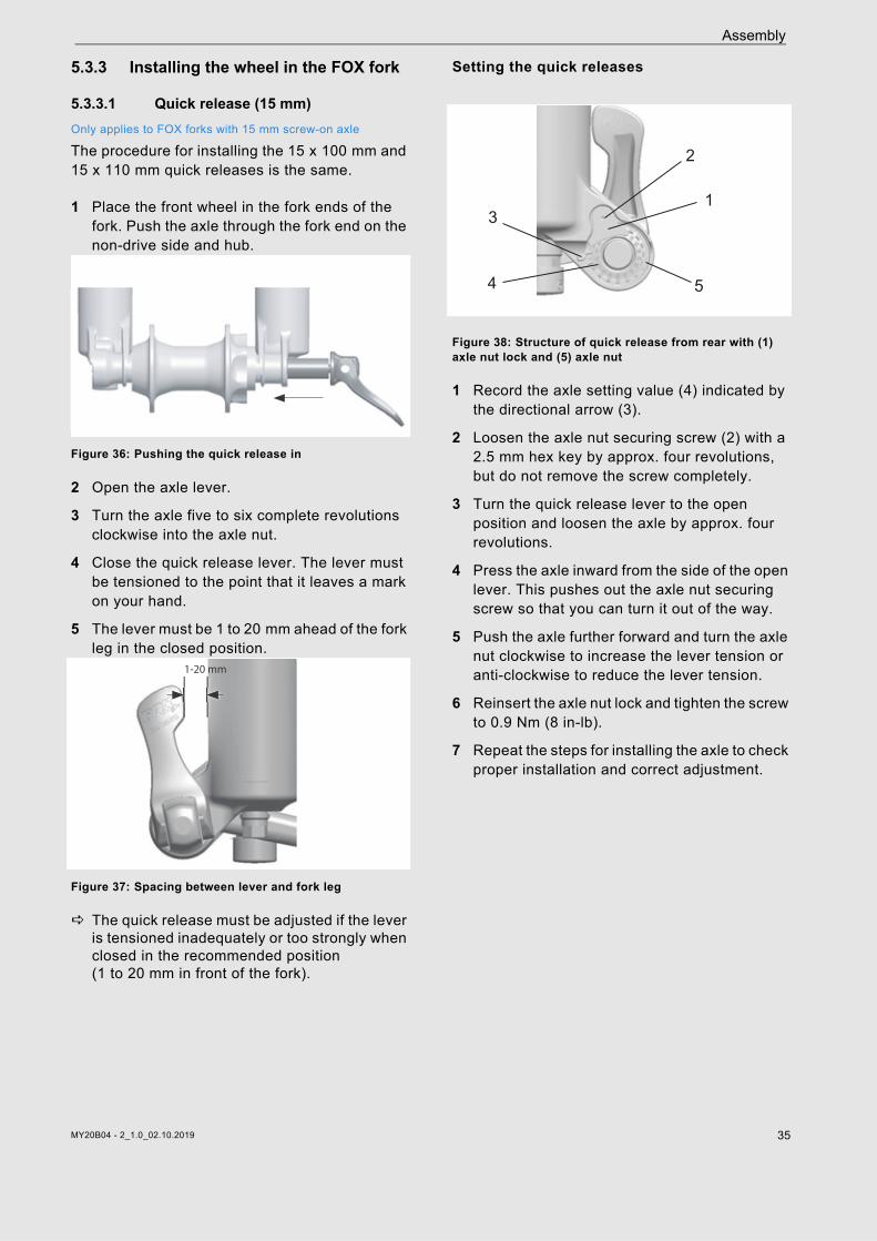
5.3.3 Installing the wheel in the FOX fork
5.3.3.1 Quick release (15 mm) Only applies to FOX forks with 15 mm screw-on axle
The procedure for installing the 15 x 100 mm and 15 x 110 mm quick releases is the same.
1 Place the front wheel in the fork ends of the fork. Push the axle through the fork end on the non-drive side and hub.
Figure 36: Pushing the quick release in
2 Open the axle lever.
3 Turn the axle five to six complete revolutions clockwise into the axle nut.
4 Close the quick release lever. The lever must be tensioned to the point that it leaves a mark on your hand.
5 The lever must be 1 to 20 mm ahead of the fork leg in the closed position.
Figure 37: Spacing between lever and fork leg
The quick release must be adjusted if the lever is tensioned inadequately or too strongly when closed in the recommended position (1 to 20 mm in front of the fork).
Setting the quick releases
Figure 38: Structure of quick release from rear with (1) axle nut lock and (5) axle nut
1 Record the axle setting value (4) indicated by the directional arrow (3).
2 Loosen the axle nut securing screw (2) with a 2.5 mm hex key by approx. four revolutions, but do not remove the screw completely.
3 Turn the quick release lever to the open position and loosen the axle by approx. four revolutions.
4 Press the axle inward from the side of the open lever. This pushes out the axle nut securing screw so that you can turn it out of the way.
5 Push the axle further forward and turn the axle nut clockwise to increase the lever tension or anti-clockwise to reduce the lever tension.
6 Reinsert the axle nut lock and tighten the screw to 0.9 Nm (8 in-lb).
7 Repeat the steps for installing the axle to check proper installation and correct adjustment.
1-20 mm
1
2
3
4 5
MY20B04 - 2_1.0_02.10.2019 35

Assembly
5.3.3.2 Kabolt axleOnly applies to FOX forks with Kabolt axles
The procedure for installing the 15 x 100 mm and 15 x 110 mm Kabolt axles is the same.
1 Place the front wheel in the fork ends of the fork. Push the Kabolt axle through the fork end on the non-drive side and hub.
Figure 39: Pushing the Kabolt axle in
2 Tighten the Kabolt axle screw to 17 Nm (150 in-lb) with a 6 mm hex key.
5.3.4 Checking the stem and handlebars
5.3.4.1 Checking connections
1 Stand in front of the pedelec to check whether the handlebars, stem and fork steerer are firmly attached to one another. Clamp the front wheel between your legs. Grasp the handlebar grips.
2 Try to twist the handlebars towards the front wheel.
The stem must not move or twist.
5.3.4.2 Firm hold
1 Place your entire body weight on the handlebars with the quick release lever closed to check that the stem is firmly in place.
The handlebars shaft must not move downwards in the fork steerer.
2 If the handlebars shaft should move in the fork steerer, increase the quick release lever tensioning. To do so, turn the knurled nut slightly in a clockwise direction with the quick release lever open.
3 Close the lever and check the stem is firmly in position.
5.3.4.3 Checking the headset backlash
1 To check the handlebar headset backlash, close the quick release lever on the stem.
2 Place the fingers of one hand on the upper headset cup. Pull the front wheel brake with the other hand and try to push the pedelec backwards and forwards.
3 The headset cup halves must not move towards one another while you are doing this. Note that there may be noticeable backlash due to worn-out bearing bushes or brake lining backlash in suspension forks and disc brakes.
4 If there is headset backlash in the steering headset, you must adjust it as soon as possible; otherwise, the headset will become damaged. You must make the adjustment as described in the stem manual.
5.4 Pedelec sale Complete Pedelec pass on the operating
instructions envelope.
Note down the battery key manufacturer and its number.
Adjust the pedelec to the rider; see Section 6.5.
Set the stand and shifter.
Instruct the operator or rider on how to use all the pedelec's functions.
MY20B04 - 2_1.0_02.10.2019 36

Operation
6 Operation
6.1 Risks and hazards
Injuries and death caused by other road users
Other road users, trucks, cars or pedestrians often underestimate the speed of pedelecs. Likewise, other road users frequently do not see pedelecs. This may cause a crash with serious injuries or even death. Wear a cycling helmet and high-visibility,
reflective clothing.
Always take a defensive approach to riding.
Avoid the blind spots of vehicles turning off. Reduce speed as a precaution when other road users turn right.
Injuries and death caused by riding incorrectly
A pedelec is not a bicycle. Incorrect riding and underestimated speeds soon result in hazardous situations. This may cause a fall with serious injuries or even death. If you haven't ridden on a pedelec for some
time, get accustomed to the speed first before you ride at speeds over 12 km/h. Increase the level of assistance gradually.
Practice braking hard on a regular basis.
Take and complete a riding safety course.
Crash caused by loose clothing
Shoe laces, scarves and other loose items may become entangled in the spokes on the wheels and on the chain drive. This may cause a crash with injuries.
Wear sturdy footwear and close-fitting clothing.
WARNING!
CAUTION!
Risk of fire and burning due to hot motor
The motor housing becomes hot when riding. Touching it may cause burns to the skin or other objects.
Never touch the motor housing directly after riding.
Never place the pedelec on a flammable surface, such as grass or wood, directly after use.
Crash caused by soiling
Heavy soiling can impair pedelec functions, such as braking. This may cause a crash with injuries.
Remove coarse soiling before riding.
Crash caused by poor road conditions
Loose objects, such as branches and twigs, may become caught in the wheels and cause a crash with injuries.
Be aware of the road conditions.
Ride slowly and brake in good time.
Notice
Heat or direct sunlight can cause the tyre pressure to increase above the permitted maximum pressure. This can destroy the tyres.
Never park the pedelec in the sun.
On hot days, regularly check the tyre pressure and adjust it as necessary.
When riding downhill, high speeds may be reached. The pedelec is only designed to exceed a speed of 25 km/h for short intervals. The tyres in particular can fail if exposed to a continuous load.
Use the brakes to decelerate the pedelec if you reach speeds greater than 25 km/h.
CAUTION!
MY20B04 - 2_1.0_02.10.2019 37

Operation
6.1.1 Personal protective equipment It is recommended that you wear a suitable cycling helmet, sturdy footwear and typical, close-fitting, reflective cycling clothing.
6.2 Tips for a greater rangeThe pedelec's range depends on many influencing factors. A single battery charge may only last fewer than 20 kilometres but much more than 100 is also possible. There are a few tips which will generally help you maximize range.
Pedalling frequency
Ride using pedalling frequencies of over 50 revolutions per minute. This optimises the electric drive’s efficiency.
Avoid pedalling very slowly.
Weight
Minimise the total weight of pedelec and baggage.
Stopping & starting
Ride long distances at a constant speed.
Avoid stopping and starting frequently.
Gear shift
Use a low gear when setting off and on hills.
Switch up a gear depending on the speed and terrain.
Follow the gear recommendations on the display screen.
Tyre pressure
Always use the maximum permitted tyre pressure.
Motor power indicator
Adjust your riding to the displayed motor power. A long bar indicates high power consumption.
Battery & temperature
Electrical resistance increases as the temperature drops. Battery performance is reduced. As a result, you should expect the range to be shorter than normal in winter.
Use thermal protection sleeves on the battery in winter.
Notice
Moisture penetrating at low temperatures may impair individual functions due to the open structural design.
Always keep the pedelec dry and free from frost.
If the pedelec is to be used at temperatures below 3 °C, the specialist dealer must carry out an inspection and prepare it for winter use.
Off-road riding subjects the joints in the arms to severe strain.
Take a break from riding every 30 to 90 minutes, depending on the road surface conditions
MY20B04 - 2_1.0_02.10.2019 38

MY20B04 - 2_1.0_02.10.2019 39
Operation
6.3 Error messages6.3.1 Error message displayParts of the electronic drive system are permanently monitored during use and charging. If an error is detected, the error code detected appears on the display screen. Press any button on the control panel to switch the display screen back to the default screen.
Power assistance is automatically stopped in the case of specific error codes. There is no longer power assistance, but you can still use the pedelec in a conventional manner without the drive.
If an error is shown, correct it using the measures described in the following table and/or contact your specialist dealer.
Powercore battery error message
Symptom Cause Remedy
A torque sensor error is displayed on starting up.
Are you applying pressure to the pedals when switching on?
Press the On-Off button again and avoid applying pressure to the pedals.
An error is displayed on starting up.
Are you pressing other buttons while pushing the On-Off button?
Press the On-Off button again and avoid pushing other buttons at the same time.
Table 25: Error solution when switching on
Symptom Cause Remedy
All LEDs flash followed by an error code The battery is defective. Contact your specialist dealer.
An LED is flashing The battery is flat. Charge the battery.
Torn charger plug cover The battery connector is loose. Do not use battery. Contact your specialist dealer.
Battery not working
Press button to switch on.
The battery is too cold. Bring into warm environment.
The battery is too hot. Leave battery to cool down.
Battery deep-discharged due to incorrect storage. Contact your specialist dealer.
Range too shortThe battery is too cold. A shorter range is normal in winter.
Loss of capacity due to incorrect storage or natural ageing. Replace battery.
Table 26: Error solution for battery

Operation
6.4 Instruction and customer serviceYour supplying specialist dealer will provide customer service. Contact details can be found on the pedelec pass for these operating instructions. If you are unable to contact your specialist dealer, you will find other specialist dealers online at www.bulls.de. The specialist dealer will explain all the pedelec functions to you in person, this being when the specialist dealer hands over the pedelec at the latest. These operating instructions are provided to you with every pedelec, so that you can consult them at a later stage.
Your specialist dealer will also be happy to assist you in the future whether you require maintenance, conversion or repair.
6.5 Adjusting the pedelec
Only a correctly adjusted pedelec will guarantee the desired ride comfort and health-promoting activity. Therefore adjust the saddle, the handlebars and the suspension to your body and your preferred riding style before the first ride.
6.5.1 Adjusting the saddle
6.5.1.1 Adjusting the saddle tilt
The saddle tilt must be adjusted to the seat height, the saddle and handlebar position, and the saddle shape to ensure an optimum fit. The seating position can be optimised in this way if needed. First, readjust the saddle after finding the handlebar position you prefer.
Place the saddle tilt in the horizontal position to adjust the pedelec to your needs for initial use.
Figure 40: Horizontal saddle tilt
6.5.1.2 Determining the seat height
To determine the seat height safely, either push the pedelec near to a wall, so that you can lean on the wall to support yourself or ask another person to hold the pedelec for you.
1 Climb onto the bicycle.
2 Place your heel on the pedal and extend your leg, so that the pedal is at the lowest crank rotation point.
The rider sits straight on the saddle if the seat is at an optimum height. If this is not the case, you can adjust the length of the seat post to your needs.
Figure 41: Optimal saddle height
Crash caused by incorrectly adjusted torques
If a screw is fastened too tightly, it may break. If a screw is not fastened enough, it may loosen. This will cause a crash with injuries.
Always observe the indicated torques on the screw or in the operating instructions.
CAUTION!
MY20B04 - 2_1.0_02.10.2019 40
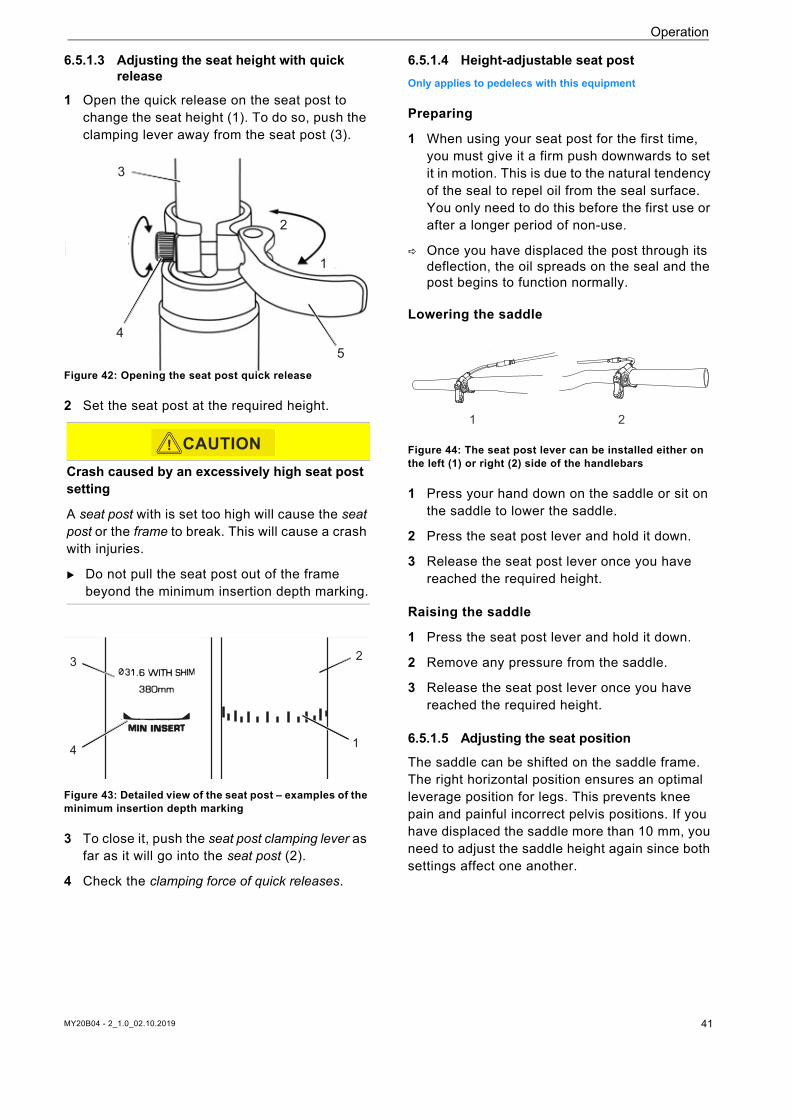
Operation
6.5.1.3 Adjusting the seat height with quick release
1 Open the quick release on the seat post to change the seat height (1). To do so, push the clamping lever away from the seat post (3).
Figure 42: Opening the seat post quick release
2 Set the seat post at the required height.
Figure 43: Detailed view of the seat post – examples of the minimum insertion depth marking
3 To close it, push the seat post clamping lever as far as it will go into the seat post (2).
4 Check the clamping force of quick releases.
6.5.1.4 Height-adjustable seat postOnly applies to pedelecs with this equipment
Preparing
1 When using your seat post for the first time, you must give it a firm push downwards to set it in motion. This is due to the natural tendency of the seal to repel oil from the seal surface. You only need to do this before the first use or after a longer period of non-use.
Once you have displaced the post through its deflection, the oil spreads on the seal and the post begins to function normally.
Lowering the saddle
Figure 44: The seat post lever can be installed either on the left (1) or right (2) side of the handlebars
1 Press your hand down on the saddle or sit on the saddle to lower the saddle.
2 Press the seat post lever and hold it down.
3 Release the seat post lever once you have reached the required height.
Raising the saddle
1 Press the seat post lever and hold it down.
2 Remove any pressure from the saddle.
3 Release the seat post lever once you have reached the required height.
6.5.1.5 Adjusting the seat position
The saddle can be shifted on the saddle frame. The right horizontal position ensures an optimal leverage position for legs. This prevents knee pain and painful incorrect pelvis positions. If you have displaced the saddle more than 10 mm, you need to adjust the saddle height again since both settings affect one another.
Crash caused by an excessively high seat post setting
A seat post with is set too high will cause the seat post or the frame to break. This will cause a crash with injuries.
Do not pull the seat post out of the frame beyond the minimum insertion depth marking.
3
45
1
2
3
CAUTION!
3
4
2
1
etie
rt w
se Po
sition z
ur Be
aber in e
inem
späte
re
ochmals m
ontiere
n.
Sie d
en mitg
eliefe
rten W
inkel m
it de
orricht
ung un
d stecke
n Sie d
ie Hüll
e in d
ie
nvorric
htun
g.
derRe
mote
hebel
5
Ode
r
28
1 2
MY20B04 - 2_1.0_02.10.2019 41

Operation
To adjust the seat position safely, either push the pedelec near to a wall, so that you can lean on the wall to support yourself or ask another person to hold the pedelec for you.
1 Climb onto the bicycle.
2 Place the pedals into the vertical position with your feet.
The rider is sitting in the optimal sitting position if the knee cap perpendicular line runs through the pedal axle.
3.1If the perpendicular line crosses behind the pedal, bring the saddle forward.
3.2If the perpendicular line crosses in front of the pedal, bring the saddle back.
4 Move the saddle within its permitted displacement range only (marked on the saddle stay).
Figure 45: Knee cap perpendicular line
6.5.2 Adjusting the handlebars
6.5.3 Adjusting the stem
6.5.3.1 Adjusting the height of the handlebars
1 Open the stem clamping lever.
Figure 46: Open (2) and closed (1) stem clamping lever; by.schulz speedlifter used as an example
2 Pull the locking lever on the stem up, and simultaneously pivot the handlebars into the desired position.
You feel the locking lever click into place.
The handlebar settings must only be adjusted while the pedelec is stationary.
Unfasten and adjust the designated screw connections, and clamp them with the maximum tightening torque for the clamping screws of the handlebars.
90°
Crash caused by incorrectly set clamping force
Excessively high clamping force will damage the quick release and cause it to lose its function. Insufficient clamping force will cause a detrimental transmission of force. This can cause components to break. This will cause a crash with injuries.
Never fasten a quick release using a tool (e.g. hammer or pliers).
Only use the clamping lever with the specified set clamping force.
Crash caused by loose stem
Incorrectly fastened screws may come loose due to impact. The stem may no longer be firmly fixed in its position as a result. This will cause a crash with injuries.
Check the handlebars and the quick release system are firmly in position after the first two hours of riding.
CAUTION!
CAUTION!
1
2
MY20B04 - 2_1.0_02.10.2019 42

Operation
Figure 47: Pulling the locking lever upwards; by.schulz speedlifter used as an example
3 Pull out the handlebars to the required height.
4 Close the stem clamping lever.
6.5.3.2 Adjusting the quick release clamping force
If the clamping lever on the handlebars cannot be moved into its final position, unscrew the knurled nut.
Tighten the knurled nut on the seat post if the seat post clamping lever's clamping force is not sufficient.
If you are unable to set the clamping force, the specialist dealer will need to check the quick release.
6.5.4 Setting the brakeThe brake lever grip distance can be adjusted to ensure that it can be reached more easily. The pressure point can also be adjusted to the rider's preferences.
Contact your specialist dealer if your brake is not described in these instructions.
6.5.4.1 Setting the grip distance on a Magura HS33 brake lever
Only applies to pedelecs with this equipment
You can adjust the brake lever position (grip distance) to your requirements. Such adjustment does not affect the pressure point or the position of the brake linings.
Use a T25 TORX® wrench to turn the setting screw (1) to adjust the grip distance.
Figure 48: Setting the grip distance on a Magura HS 33 brake lever
Turn the setting screw anti-clockwise towards minus (–).
The brake lever moves closer to the handlebar grip.
Turn the setting screw clockwise towards plus (+).
The brake lever moves away from the handlebar grip.
6.5.4.2 Setting the grip distance on a Magura HS22 brake lever
Only applies to pedelecs with this equipment
You can adjust the brake lever position (grip distance) to your requirements.
Use a T25 TORX® wrench to turn the setting screw (1) to adjust the grip distance.
Figure 49: Setting the grip distance on a Magura HS 33 brake lever
1
2
MY20B04 - 2_1.0_02.10.2019 43

Operation
Pull the brake lever gently and hold.
Move the slider (2) outwards (–) to Position II or III.
The brake handle moves closer to the handlebars.
The brake linings move closer to the rim.
The pressure point activates sooner.
Move the slider inwards (+) to Position II or I. The brake lever moves away from the
handlebars.
The brake linings move away from the rim.
The pressure point activates later.
6.5.4.3 Setting the grip distance on a Magura disc brake lever
Only applies to pedelecs with this equipment
You can adjust the brake lever position (grip distance) to your requirements. Such adjustment does not affect the pressure point or the position of the brake linings.
Use a T25 TORX® wrench to turn the setting screw (1) to adjust the grip distance.
Figure 50: Setting the grip distance on a Magura disc brake lever
Turn the setting screw/twist knob (5) anti-clockwise towards minus (–).
The brake lever moves closer to the handlebar grip.
Turn the setting screw clockwise towards plus (+). The brake lever moves away from the handlebar
grip.
6.5.4.4 Setting the pressure point on a Magura brake lever
The pressure point setting is adjusted using the twist knob.
Turn the twist knob towards the plus (+) symbol. The brake lever moves closer to the handlebar
grip. Re-adjust the grip distance as necessary.
The lever pressure point activates sooner.
Figure 51: Using the twist knob (1) to adjust the pressure point
Crash caused by incorrectly set grip distance
If brake cylinders are set or installed incorrectly, braking power may be lost completely at any time. This may cause a crash with serious injuries.
Once the grip distance has been set, check the position of the brake cylinder. Correct if necessary.
Crash caused by incorrectly set grip distance
If brake cylinders are set incorrectly or installed wrongly, the braking power may be lost at any time. This may cause a crash with injuries.
Ensure that the fully applied brake lever is at a minimum distance of 20 mm from the handlebars (4).
WARNING!
WARNING!
Brake failure due to incorrect setting
If the pressure point is set with brakes where the brake linings and brake disc have reached their wear limit, the brakes may fail and cause an accident with injury.
Before you set the pressure point, ensure that the brake linings and brake disc have not reached their wear limit.
WARNING!
1
MY20B04 - 2_1.0_02.10.2019 44

Operation
6.5.5 Retracting the brake liningsDisc brakes require wearing-in time. The braking force increases over time. You therefore need to be aware that the braking force may increase during the wearing-in period. The same happens after brake pads or discs are replaced.
Accelerate pedelec to about 25 km/h. Brake pedelec until it comes to a halt. Repeat process 30–50 times. The brake disk is retracted and provides
optimal braking power.
6.5.6 Adjusting Suntour forkOnly applies to pedelecs with this equipment
The adjustment shown here represents a basic setting. The rider should change the basic setting to suit the surface and his/her preferences.
It is advisable to make a note of the basic setting. This way, it can be used as the starting point for subsequent, optimised settings and to safeguard against unintentional changes.
6.5.6.1 Adjusting the negative deflection
Negative deflection depends on the rider's weight and sitting position. The recommended negative deflection is between 15% (hard) and 30% (soft) of the total fork deflection.
6.5.6.2 Adjusting the steel suspension fork negative deflection
Only applies to pedelecs with this equipment
You can adjust the tensioning in the fork spring to the rider's weight and their preferred riding style. This reduces the negative deflection in the fork.
Figure 52: Negative deflection setting wheel on the suspension fork crown
1 You will find the negative deflection setting wheel beneath the plastic cover on the crown. Remove the plastic cover.Turn the negative deflection setting wheel in a clockwise direction to increase the spring pre-tensioning. Turn the negative deflection setting wheel in an anti-clockwise direction to decrease the spring pre-tensioning.
You will have made the ideal setting when the shock absorber deflects 3 mm when subject to the rider's weight.
3 Replace the plastic cover on the crown after making the setting.
6.5.6.3 Adjusting the air suspension fork negative deflection
Only applies to pedelecs with this equipment
The air valve is located beneath the valve cap on the crown of the left-hand shock absorber. Unscrew the valve cap.
Figure 53: Screw caps in different designs
Crash caused by incorrectly set suspension
If the suspension is set incorrectly, the fork may become damaged, meaning problems may occur when steering. This will cause a crash with injuries.
Never ride the pedelec without air in the air suspension fork.
Never use the pedelec without adjusting the suspension fork to the rider's weight.
Notice
Settings on the chassis change riding performance significantly. You need to get used to the pedelec and break it in to prevent accidents.
CAUTION!
MY20B04 - 2_1.0_02.10.2019 45

Operation
1 Attach a high-pressure damper pump to the air valve.
2 Pump air suspension fork to the required pressure. Observe the levels in the Suntour filling pressure table. Never exceed the recommended maximum air pressure.
3 Detach high-pressure damper pump.
4 Measure the distance between the crown and the dust seal. This distance is total deflection of the fork.
5 Push a temporarily attached cable tie downward against the dust seal.
6 Put on your normal cycling clothing, including luggage.
7 Sit on the pedelec in your usual riding position and support yourself against an object, such as a wall or tree.
8 Get off the pedelec without allowing it to deflect.
9 Measure distance between the dust seal and the cable tie.
This measurement is the negative deflection. The recommended value is between 15% (hard) and 30% (soft) of the total fork deflection.
10 Increase or reduce air pressure until you have reached the desired negative deflection.
If the negative deflection is correct, turn the valve cap in a clockwise direction.
If you are unable to achieve the desired negative deflection, an internal adjustment may be needed. Contact your specialist dealer.
6.5.6.4 Adjusting the air suspension fork rebound
Only applies to pedelecs with this equipment
The rebound setting depends on the negative deflection setting: A higher negative deflection requires a lower rebound setting.
1 Turn the Suntour rebound screw in a clockwise direction to the closed position until it stops.
Figure 54: Suntour rebound screw (2), fork (1)
2 Turn the Suntour rebound screw slightly in an anti-clockwise direction.
3 Adjust the rebound in such a way that the fork rebounds quickly, but without bottoming out upward. Bottoming out refers to when the fork rebounds too quickly and stops moving abruptly once it has reached the full rebound distance. You can hear and feel a slight impact when this happens.
6.5.7 Adjusting the FOX forkOnly applies to pedelecs with this equipment
Rider weight AION, NEX XCR 32, XCR 34
< 55 kg 35 - 50 psi 40 - 55 psi
55 - 65 kg 50 - 60 psi 55 - 65 psi
65 - 75 g 60 - 70 psi 65 - 75 psi
75 - 85 kg 70 - 85 psi 75 - 85 psi
85 - 95 kg 85 - 100 psi 85 - 95 psi
< 100 kg + 105 psi + 100 psi
Maximum air pressure 150 psi 180 psi
Table 27: Suntour filling pressure table for air forks
Crash caused by incorrectly set suspension
If the suspension is set incorrectly, the fork may become damaged, meaning problems may occur when steering. This will cause a crash with injuries.
Never ride the pedelec without air in the air suspension fork.
Never use the pedelec without adjusting the suspension fork to the rider's weight.
12
CAUTION!
MY20B04 - 2_1.0_02.10.2019 46

Operation
The adjustment shown here represents a basic setting. The basic setting can be adjusted to the riding surface and personal preferences.
6.5.7.1 Adjusting the negative deflection
Negative deflection depends on the rider's weight and sitting position. The recommended negative deflection is between 15% (hard) and 20% (soft) of the total fork deflection depending on preferences and pedelec use.
When adjusting the negative deflection, ensure that each pressure level adjuster is in an open position, i.e. each pressure level adjuster has been turned in an anti-clockwise direction until it goes no further.
The pressure is to be measured at an ambient temperature of 21 to 24 °C.
1 The air valve is located beneath a blue valve cap on the crown of the left-hand shock absorber. Unscrew the valve cap in an anti-clockwise direction.
2 Attach a high-pressure damper pump to the air valve.
3 Pump the suspension fork to the required pressure. Observe the levels in the FOX filling pressure table. Never exceed the maximum air pressure or fall below the minimum air pressure recommended in the table.
4 Detach high-pressure damper pump.
5 Measure the distance between the crown and the fork's dust wiper. This distance is total deflection of the fork.
6 Push the O-ring downwards against the fork's dust wiper. If there is no O-ring, attach a cable tie to the stanchion temporarily.
7 Put on your normal cycling clothing, including luggage.
8 Sit on the pedelec in your usual riding position and support yourself against an object, such as a wall or tree.
9 Get off the pedelec without the suspension fork deflecting.
10 Measure the distance between the dust wiper and the O-ring or cable tie.
This measurement is the negative deflection. The recommended value is between 15% (hard) and 20% (soft) of the total fork deflection.
11 Increase or reduce the air pressure until you have reached the desired negative deflection.
If the negative deflection is correct, turn the blue valve cap in a clockwise direction.
Notice
Settings on the chassis change riding performance significantly. You need to get used to the pedelec and break it in to prevent accidents.
It is recommended to note down the determined negative deflection and rebound levels. This way, the levels can be used as a starting point for subsequent, optimised settings and as a safeguard against unintentional changes.
Rider weight Rhythm 34 Rhythm 36
Minimum air pressure 40 psi (2.8 bar) 40 psi (2.8 bar)
54 - 59 kg 58 psi 55 psi
59 - 64 kg 63 psi 59 psi
64 - 68 kg 68 psi 63 psi
68 - 73 kg 72 psi 67 psi
73 - 77 kg 77 psi 72 psi
77 - 82 kg 82 psi 76 psi
82 - 86 kg 86 psi 80 psi
86 - 91 kg 91 psi 85 psi
91 - 95 kg 96 psi 89 psi
95 - 100 kg 100 psi 93 psi
100 - 104 kg 105 psi 97 psi
104 - 109 kg 110 psi 102 psi
109 - 113 kg 114 psi 106 psi
Maximum air pressure 120 psi (8.3 bar) 120 psi (8.3 bar)
Table 28: FOX filling pressure table for air fork
If you are unable to achieve the desired negative deflection, internal settings may need to be changed. Contact your specialist dealer.
MY20B04 - 2_1.0_02.10.2019 47

Operation
6.5.7.2 Adjusting the rebound
The rebound defines the speed at which the fork rebounds after being loaded. The rebound setting depends on the air pressure setting. A higher negative deflection requires a lower rebound setting.
1 Turn the FOX rebound adjuster in a clockwise direction to the closed position until it stops.
Figure 55: FOX rebound adjuster (1) on the fork end
2 Turn the FOX rebound adjuster slightly in an anti-clockwise direction.
3 Adjust the rebound in such a way that the fork rebounds quickly, but without bottoming out upward. Bottoming out refers to when the fork rebounds too quickly and stops moving abruptly once it has reached the full rebound distance. You can hear and feel a slight impact when this happens.
6.5.8 Setting the Suntour rear frame damper
Only applies to pedelecs with this equipment
6.5.8.1 Adjusting the negative deflection
Negative deflection depends on the rider's weight and sitting position. The recommended negative deflection should be between 25% and 30% of the total rear frame damper deflection, depending on preferences and pedelec use.
When adjusting the negative deflection, ensure that the pressure level adjuster is in an open position, i.e. the lockout lever is in the OPEN position.
1 Remove the valve cap from the air valve.
2 Attach a high-pressure damper pump.
3 Adjust the rear frame damper air pressure to the rider's weight.
4 Detach high-pressure damper pump.
5 Measure the distance between the air chamber seal and the end of the rear frame damper. This gap is the total rear frame damper deflection.
6 Put on your normal cycling clothing, including luggage.
7 Sit on the pedelec in your usual riding position and support yourself against an object, such as a wall or tree.
8 Push the O-ring downwards against the air chamber seal.
9 Get off the pedelec without the suspension fork deflecting.
Measure the distance between the air chamber seal and the O-ring. This measurement is the negative deflection. The recommended value is between 25% (hard) and 30% (soft) of the total rear frame damper deflection.
10 Increase or reduce the air pressure until you have reached the desired negative deflection.
If the negative deflection is correct, fasten the valve cap onto the valve.
6.5.8.2 Adjusting the rebound
The rebound defines the speed at which the rear frame damper rebounds after being loaded. The rebound setting depends on the air pressure setting. Higher sag settings require lower rebound settings.
Notice
If the air pressure in the rear frame damper is exceeded or undershot, the damper can be permanently damaged.
Do not exceed the maximum air pressure of 300 psi (20 bar).
1
MY20B04 - 2_1.0_02.10.2019 48

Operation
Figure 56: Suntour rebound adjuster wheel (1) on the rear frame damper
Turn the rebound adjuster wheel in the – direction to increase rebounding.
Turn the rebound adjuster wheel towards the + symbol to reduce compressive deflection movement.
6.5.8.3 Setting the compression
You can use the pressure damper setting to adjust the rear frame damper to the ground conditions. The pressure damper setting defines the speed at which the rear frame damper rebounds after being subjected to load or impact.
Figure 57: Suntour pressure level adjuster on the rear frame damper
Turn the pressure level adjuster towards the – symbol to increase rebounding.
Turn the pressure level adjuster towards the + symbol to reduce compressive deflection movement.
6.5.9 Setting the FOX rear frame damperOnly applies to pedelecs with this equipment
6.5.9.1 Adjusting the negative deflection
Negative deflection depends on the rider's weight and sitting position. The recommended value is between 25% (hard) and 30% (soft) of the total rear frame damper deflection.
1 Turn the pressure level adjuster to the OPEN position.
2 Attach a high-pressure damper pump to the air valve.
3 Adjust the rear frame damper air pressure to the rider's weight.
4 Slowly compress the damper to over 25 % of the deflection 10 times until you have reached the desired pressure.
This equalises the air pressure between the positive and negative air chambers. The high-pressure damper pump pressure gauge changes.
5 Remove the high-pressure damper pump.
Figure 58: FOX rear frame damper
1
1
Notice
If the air pressure in the rear frame damper is exceeded or undershot, the damper can be permanently damaged.
Do not exceed the maximum air pressure of 350 psi (24.1 bar). The minimum air suspension pressure of 50 psi (3.4 bar) must be complied with.
25-30%2
1
34
5
MY20B04 - 2_1.0_02.10.2019 49

Operation
6 Measure the distance between the air chamber seal (1) and the end of rear frame damper (3). This gap is the total deflection for the rear frame damper (5).
7 Sit on the pedelec in your usual riding position and support yourself against an object, such as a wall or tree.
8 Push the O-ring (4) downwards against the air chamber seal (1).
9 Get off the pedelec without the suspension fork deflecting.
Measure the distance between the air chamber seal (1) and the O-ring (4). This measurement is the negative deflection (2). The recommended value is between 25% (hard) and 30% (soft) of the total deflection for the rear frame damper (5).
10 Increase or reduce the air pressure until you have reached the desired negative deflection.
6.5.9.2 Adjusting the rebound
The rebound adjuster defines the speed at which the rear frame damper rebounds after being subjected to load or impact. The rebound setting depends on the air pressure setting. A higher negative deflection requires a lower rebound setting.
1 Attach a high-pressure damper pump to the air valve.
2 Read the air pressure.
3 Remove the high-pressure damper pump.
Figure 59: FOX rebound adjuster wheel (1) on the rear frame damper
4 Turn the rebound adjuster clockwise to the closed position until it stops.
5 Adjust the rebound setting based on the air pressure reading. Turn the rebound adjuster back anti-clockwise by the number of clicks specified in the table below.
1
Air pressure (psi) Recommended rebound setting
< 100 Open (anti-clockwise)
100 - 120 11
120 - 140 10
140 - 160 9
160 - 180 8
180 - 200 7
200 - 220 6
220 - 240 5
240 - 260 4
260 - 280 3
280 - 300 2
Table 29: Filling pressure table for the FOX air fork
MY20B04 - 2_1.0_02.10.2019 50

Operation
6.6 AccessoriesWe recommend a parking stand into which either the front wheel or rear wheel can be inserted securely for pedelecs which do not have a kickstand. The following accessories are recommended:
*System components are matched to the pannier rack and provide sufficient stability due to special transmission of force.**System components are matched to the drive system.
6.6.1 Child seat The specialist dealer will advise you on choosing a suitable child seat system for the child and the pedelec.
The specialist dealer must install the child seat the first time to ensure that it is safely fitted.
When installing a child seat, the specialist dealer makes sure that the seat and the fastening mechanism for the seat are suitable for the pedelec and that all components are installed and firmly fastened. They will also ensure that shift cables, brake cables, hydraulic and electrical cables are adjusted as necessary, the rider has optimum freedom of movement and the pedelec's maximum permitted total weight is adjusted.
The specialist dealer will provide instruction on how to handle the pedelec and the child seat.
Description Article number
Protective cover for electrical components 080-41000 ff
Panniers, system component* 080-40946
Rear wheel basket system component* 051-20603
Bicycle box system component* 080-40947
Parking stand universal stand XX-TWO14B
Table 30: Accessories
Crash caused by incorrect child seat
The pannier rack and down tube are unsuitable for mounting child seats and may break. Such an incorrect position may cause a crash with serious injuries for the rider and the child.
Never attach a child seat to the saddle, handlebars or down tube.
Crash caused by improper handling
When using child seats, the pedelec's handling characteristics and stability change considerably. This can cause a loss of control, a crash and injuries.
You should practice how to use the child seat safely before using the pedelec in public spaces.
WARNING!
CAUTION!
Risk of crushing due to exposed springsThe child may crush his/her fingers on exposed springs or open mechanical parts of the saddle or the seat post.
Never install saddles with exposed springs if a child seat is being used.
Never install seat posts with suspension with open mechanical parts or exposed springs if a child seat is being used.
Notice
Observe the legal regulations on the use of child seats.
Observe the operating and safety instructions for the child seat system.
Never exceed the maximum permitted total weight.
CAUTION!
MY20B04 - 2_1.0_02.10.2019 51

Operation
6.6.2 Bicycle trailers
A pedelec which is approved for towing a trailer will bear an appropriate adhesive label. You may only use bicycle trailers with a support load and weight which do not exceed the permitted values.
Figure 60: Trailer sign
The specialist dealer will advise on choosing a suitable trailer system for the pedelec. The specialist dealer must install the trailer the first time to ensure that it is safely fitted
6.6.3 Pannier rack The specialist dealer will advise on choosing a suitable pannier rack.
The specialist dealer must install the pannier rack the first time to ensure that it is safely fitted.
When installing a pannier rack, the specialist dealer makes sure that the fastening mechanism is suitable for the pedelec and that all components are installed and firmly fastened. They will also ensure that shift cables, brake cables, hydraulic cables and electrical cables are adjusted as necessary, the rider has optimum freedom of movement and the pedelec's maximum permitted total weight is adjusted.
The specialist dealer will provide instruction on how to handle the pedelec and the pannier rack.
Crash caused by brake failure
The brake will be weaker if the trailer load is excessive. The long braking distance can cause a crash or an accident and injuries.
Never exceed the specified trailer load.
Notice
The operating and safety notes for the trailer system must be observed.
The statutory regulations on the use of bicycle trailers must be observed.
Only use type-approved coupling systems.
CAUTION!
MY20B04 - 2_1.0_02.10.2019 52

MY20B04 - 2_1.0_02.10.2019 53
Operation
6.7 Before each ride 6.8 Check list before each ride Check the pedelec before each ride.
Take the pedelec out of service if you spot any anomalies. Crash caused by difficult-to-spot damage
If the pedelec topples over or you have a fall or an accident, there may be difficult-to-spot damage to components such as the brake system, quick releases or frame. This may cause a crash with injuries.
Take the pedelec out of service and have a specialist dealer carry out an inspection.
Crash caused by material fatigue
Intensive use can cause material fatigue. A component may suddenly fail in case of material fatigue. This may cause a crash with injuries.
Remove the pedelec from service immediately if there are any signs of material fatigue. Have the specialist dealer check the state.
Have the specialist dealer carry out a basic inspection regularly. During the inspection, the specialist dealer will inspect the pedelec for any signs of material fatigue on the frame, fork, suspension element mountings (if there are any) and components made of composite materials.
Carbon becomes brittle when exposed to heat radiation such as heating. This can cause the carbon part to break and result in a crash with injuries.
Never expose carbon parts on the pedelec to strong sources of heat.
CAUTION!
Check that the pedelec is complete.
Check the battery is firmly in place.
Check that the lighting, reflector and brake, for instance, are sufficiently clean.
You must check that the mudguards, the pannier rack and the chain guard are securely installed.
Check that the front and rear wheels run true. This is particularly important if the pedelec been transported or secured with a lock.
Check the valves and the tyre pressure. Adjust as necessary before each ride.
If the pedelec has a hydraulic rim brake, check whether the locking levers are fully closed in their final positions.
Check the front and rear wheel brakes to make sure that they are working properly. To do so, push the brake levers while stationary to check whether resistance is generated in the usual brake lever position. The brake must not lose any brake fluid.
Check that the riding light is working.
Check for unusual noises, vibrations, smells, staining, deformation, cracks, scores, abrasion and wear. This indicates material fatigue.
Inspect suspension system for cracks, dents, bumps, parts or leaking oil. Look at concealed sections on the pedelec's lower surface.
Use body weight to compress suspension system. Adjust to the optimum sag value if suspension is too soft.
If quick releases are used check them to make sure that they are fully closed in their end position. If quick release axle systems are used, make sure that all attachment screws are tightened to the correct torque.
Be alert to any unusual operating sensations when braking, pedalling or steering.
Check that the ABS indicator lamp lights up correctly on pedelecs with an ABS system.

MY20B04 - 2_1.0_02.10.2019 54
Operation
6.9 Using the kickstand
6.9.1 Raising the kickstand Use your foot to raise the kickstand completely
before setting off.
6.9.1.1 Parking the pedelec
Use your foot to lower the kickstand completely before parking.
Park the pedelec carefully and check that it is stable.
6.10 Using the pannier rack
Distribute the baggage as evenly as possible between the left- and right-hand side.
We recommend the use of panniers and baggage baskets.
Crash caused by a lowered kickstand
There is a risk of crashing if riding with the kickstand lowered.
Raise the kickstand completely before setting off.
Notice
The pedelec's force of weight may cause the kickstand to sink into soft ground, possible causing the pedelec to topple over as a result.
The pedelec must be parked on firm, level ground only.
It is particularly important to check that the pedelec is stable if it is equipped with accessories or loaded with baggage.
Crash caused by loaded pannier rack
The pedelec is handled differently with a loaded pannier rack, in particular when the rider needs to steer and brake. This can lead to a loss of control. This may cause a crash with injuries.
You should practice how to use a loaded pannier rack safely before using the pedelec in public spaces.
CAUTION!
CAUTION!
Crash caused by unsecured baggage
Loose or unsecured objects on the pannier rack, e.g. belts, may become caught in the rear wheel. This may cause a crash with injuries.
Objects which are fastened to the pannier rack may cover the reflectors and the riding light. Other users may not see the pedelec on public roads as a result. This may cause a crash with injuries.
Secure any objects which are attached to the pannier rack sufficiently.
Objects fastened to the pannier rack must never cover the reflectors, the headlight or the rear light.
Crushing the fingers in the spring flap
The spring flap on the pannier rack operates with a high clamping force. There is a risk of crushing the fingers.
Never allow the spring flap to snap shut in an uncontrolled manner.
Be careful where you position your fingers when closing the spring flap.
Notice
The maximum load bearing capacity is indicated on the pannier rack.
Never exceed the maximum permitted total weight when packing the pannier.
Never exceed the maximum load bearing capacity of the pannier rack.
Never modify the pannier rack.
CAUTION!

Operation
6.11 Rechargeable battery
Switch off the battery and the drive system before removing or inserting the battery.
6.11.1 Removing the battery
Figure 61: Removing the Powercore battery
1 Use your right hand to push the battery up into the frame.
The lock hook is disengaged in the frame.
2 Hold underneath the battery with your right hand. Use the key to lock it.
The lock hook releases the battery.
3 The battery will now fall out of the frame or can be pulled out of the down tube, depending on how much space there is between the battery and down tube.
4 Remove the key from the lock.
6.11.2 Inserting the battery
Figure 62: Inserting the Powercore battery
1 Insert the battery into the frame from the top.
2 Swivel the battery into the down tube. Apply a little pressure to push the battery into the frame.
3 Close the lock.
4 Remove the key.
5 Check the battery is firmly in position.
Notice
If you leave a key inserted when riding or transporting the pedelec, it may break off or the locking system may open accidentally.
Remove the key from the battery lock immediately after use.
We recommend that you attach the key to a key ring.
Notice
The battery may fall to the ground when unlocked.
Hold onto the battery firmly when unlocking it.
.
2.
3.
1
2
3
Notice
The battery can fall out of the frame due to impact or jolting.
Also secure battery with lock.
1
2
3
MY20B04 - 2_1.0_02.10.2019 55

Operation
6.11.3 Charging the battery
The battery can remain on the pedelec or can be removed for charging.
1 Remove the rubber cover from the battery.
2 Connect the mains plug of the charger to a normal domestic, grounded socket.
3 Connect the charging cable to the battery's charging port. Only use the charger supplied in the scope of delivery.
The charging process starts automatically.
The battery level indicator indicates the charge level during charging. When the drive system is switched on, the display screen will show the charging process.
The charging process is complete when the LEDs on the battery level indicator go out.
Fire caused by overheated charger
The charger heats up when charging the battery. In case of insufficient cooling, this can result in fire or burns to the hands.
Never use the charger on a highly flammable surface (e.g. paper, carpet etc.).
Never cover the charger during the charging process.
Never leave a battery charging unattended.
Electric shock caused by penetration by water
If water penetrates into the charger, there is a risk of electric shock.
Never charge the battery outdoors.
Electric shock in case of damage
Damaged chargers, cables and plug connectors increase the risk of electric shock.
Check the charger, cable and plug connector before each use. Never use a damaged charger.
Notice
If an error occurs during the charging process, a system message is displayed. Remove the charger and battery from operation immediately and follow the instructions.
Contact your specialist dealer if you are unable to recharge the battery or it is damaged.
CAUTION!
LED 1,2,3,4,5 Battery level
100 - 80%
79 - 60%
59 - 40%
39 - 20%
19 - 10%
9 - 0%
Table 31: Battery level indicator
MY20B04 - 2_1.0_02.10.2019 56

MY20B04 - 2_1.0_02.10.2019 57
Operation
6.12 Electric drive system6.12.1 Switching on the electric drive
system
A sufficiently charged battery has been inserted into the pedelec.
The battery is firmly positioned. The key has been removed.
Press the On-Off button (operating element).
or
Press the On-Off button (battery) briefly.
The indicator will switch on after a few seconds.
If the drive system is switched on, the drive is activated as soon as the pedals are moved with sufficient force.
6.12.2 Switching off the drive systemThe system switches off automatically several minutes after the last command. The following options are available to manually switch off the drive system:
Press the On-Off button (operating element).
or
Press the On-Off button (battery) for a long time.
The display and LEDs on the battery level indicator will go out.
Crash caused by lack of readiness for braking
When it is switched on, the drive system can be activated by the application of force on the pedals. There is a risk of a crash if the drive is activated unintentionally, and the brake is not reached.
Never start the electric drive system, or switch it off immediately, if the brake cannot be reached safely and reliably.
CAUTION!

MY20B04 - 2_1.0_02.10.2019 58
Operation
6.13 Control panel with display6.13.1 Using the driving light To switch on the riding light, the drive system
needs to be switched on first.
Press the headlight button. The riding light is switched on. The display
backlight is switched on.
or
Press the headlight button again. The riding light is switched off. The display
backlight is switched off.
6.13.2 Using the push assist systemThe push assist helps the rider to push the pedelec. The speed can be a maximum of 6 km/h in this case.
The tractive power of the push assist and its speed can be influenced by the selection of gear. To spare the drive, first gear is recommended for travelling uphill.
1 Press and hold down the plus rocker button.
The push assist system is activated.
2 Release the plus rocker button to switch off the push assist system.
The push assist system switches off automatically as soon as the pedelec pedals are used or the speed exceeds 6 km/h.
6.13.3 Selecting the levels of assistance Press the plus rocker button. The level of assistance is increased.
or
Press the minus rocker button. The level of assistance is reduced.
6.13.4 Changing the kilometre display unit Press and hold the settings button.The kilometre display unit changes between metric units of measure (km/h) and imperial units of measure (mph).
6.13.5 Switching the journey informationThe screen shows three pieces of journey information:
The standard setting for the display is the trip distance (TRP).
The displayed journey information can be changed and partially reset.
1 Press the settings button.
The remaining pedelec range (R) is shown.
2 Press the settings button again.
Total trip distance (T) completed by pedelec is shown.
3 Press the settings button again.
The trip distance (TRP) is shown.
6.13.5.1 Deleting the journey distance
Press the minus rocker button for a long time. The trip distance is reset to 0 km.
Screen display Function
TRP Trip distance
R Remaining pedelec range
T Total trip distance completed by pedelec

Operation
6.14 Brake
The drive force of the motor is shut off during the ride as soon as the rider no longer pedals. The drive system does not switch off when braking.
In order to achieve optimum braking results, do not pedal while braking.
Crash caused by brake failure
Oil or lubricant on the brake disc in a disc brake or on the rim of a rim brake can cause the brake to fail completely. This may cause a crash with serious injuries.
Never allow oil or lubricant to come into contact with the brake disc or brake linings or on the rim of a rim brake.
If the brake linings have come into contact with oil or lubricant, contact a dealer or a workshop to have the components cleaned or replaced.
If the brakes are applied continuously for a long time (e.g. while riding downhill for a long time), the fluid in the brake system may heat up. This may create a vapour bubble. This will cause air bubbles or any water contained in the brake system to expand. The lever travel may suddenly become wider. This may cause a crash with serious injuries.
Release the brake regularly when riding downhill for a longer period of time.
Amputation due to rotating brake disc
The brake disc in disc brakes is so sharp that it can cause serious injuries to fingers if they are inserted into the brake disc openings.
Always keep fingers well away from the rotating brake disc.
Burns caused by heated brake
The brakes may become very hot during operation. There is a risk of burns or fire in case of contact.
Never touch the components of the brake directly after the ride.
WARNING!
CAUTION!
Crash after cleaning or storage
The brake system is not designed for use on a pedelec which is placed on its side or turned upside down. The brake may not function correctly as a result. This can cause a crash, which may result in injuries.
If the pedelec is placed on its side or turned upside down, apply the brake a couple of times before setting off to ensure that it works as normal.
Never use the pedelec if it no longer brakes as normal. Consult a specialist dealer.
Crash caused by wet conditions
The tyres may slip on wet roads. In wet conditions you must also expect a longer braking distance. The braking sensation differs from the usual sensation. This can cause loss of control or a crash, which may result in injuries.
Ride slowly and brake in good time.
Crash caused by incorrect use
Handling the brake improperly can lead to loss of control or crashes, which may result in injuries.
Shift your body weight backwards and down as far as possible.
Practice braking and emergency braking before using the pedelec in public spaces.
Never use the pedelec if you can feel no resistance when you grip the brake handle. Consult a specialist dealer.
CAUTION!
MY20B04 - 2_1.0_02.10.2019 59

Operation
6.14.1 Using the brake lever
Figure 63: Front (2) and rear (1) brake lever; Shimano brake used as an example
Push the left brake lever for the front wheel brake and the right lever for the rear wheel brake until the desired speed is reached.
6.14.2 Using the back-pedal brakeOnly applies to pedelecs with this equipmentThe best braking effect is achieved if the pedals are in the 3 o'clock and 9 o'clock position when braking. To bridge the free travel between the riding movement and the braking movement, it is recommendable to pedal a little beyond the 3 o'clock and 9 o'clock position before you pedal in the opposite direction to the direction of travel and start braking.
Pedal in the opposite direction to the direction of travel until the desired speed has been reached.
6.15 Suspension and damping
6.15.1 Adjusting the compression in the Fox fork
Only applies to pedelecs with this equipmentThe compression adjuster makes it possible to make quick adjustments to the suspension behaviour of the fork to suit changes in terrain. It is intended for adjustments made during the ride.
Figure 64: FOX compression adjuster with the OPEN (1) and HARD (2) positions
Compression damping is lowest in the OPEN position, making the fork feel softer. Use the HARD position if you want to the fork feel stiffer and you are riding on soft ground. The lever positions between the OPEN and HARD positions enable fine adjustment of compression damping.
We recommend setting the lever of the compression adjuster to the OPEN mode position first.
6.15.2 Adjusting the compression in the Fox damper
Only applies to pedelecs with this equipmentThe compression adjuster makes it possible to make quick adjustments to the suspension behaviour of the damper to suit changes in terrain. It is intended for adjustments made during the ride.
Figure 65: FOX compression adjuster on the rear frame damper with the OPEN (1), MEDIUM (2) and HARD (3) positions
Use the OPEN position for rough descents, the MEDIUM position for rough terrain and the HARD position for efficient climbing. First set the compression adjuster to the OPEN position.
Figure 66: Fine adjustment of the OPEN position is made using the adjuster (4)
The FOX rear frame damper features fine adjustment for the OPEN position.
12
11
2
1
2
3
4
3
21
MY20B04 - 2_1.0_02.10.2019 60

Operation
We recommend that fine adjustments be made when the compression adjuster is in the MEDIUM or HARD position.
Pull out the adjuster. Turn the adjuster to position 1, 2 or 3. Setting
1 is for the softest riding performance, whereas 3 is for the hardest.
Press the adjuster in to lock in the setting.
6.15.3 Adjusting the compression in the Suntour fork
Only applies to pedelecs with this equipmentThe compression adjuster makes it possible to make quick adjustments to the suspension behaviour of the fork to suit changes in terrain. It is intended for adjustments made during the ride.
Figure 67: Suntour compression adjuster with the OPEN (1) and LOCK (2) positions
Compression damping is lowest in the OPEN position, making the fork feel softer. Use the LOCK position if you want the fork to feel stiffer and you are riding on soft ground. The lever positions between the OPEN and LOCK positions enable fine adjustment of compression damping.
We recommend setting the lever of the compression adjuster to the OPEN position first.
6.15.4 Adjusting the compression in a Suntour damper
Only applies to pedelecs with this equipmentThe compression adjuster makes it possible to make quick adjustments to the suspension behaviour of the damper to suit changes in terrain. It should never be used while riding on rough terrain.
Figure 68: Suntour compression adjuster open (1)
Use the OPEN position for rough descents and the LOCK position for efficient climbing. First set the compression adjuster to the OPEN position.
Figure 69: Suntour compression adjuster closed (2)
1
2
1
2
MY20B04 - 2_1.0_02.10.2019 61

Operation
6.15.5 Adjusting the rebound in a RockShox damper
Only applies to pedelecs with this equipmentThe rebound damper determines the speed at which the fork rebounds to full length after deflection. This speed affects the wheel's contact with the ground and thus has an influence on control and efficiency. The rear frame damper should rebound fast enough to sustain traction without producing an erratic or bumpy sensation. If rebound damping is too tight, the rear frame damper is unable to rebound fast enough before the next impact. The rebound damper for the rear wheel is located in the rear frame damper.
Figure 70: Setting the rebound damper strength on the rear frame damper setting wheel (1)
Turn the setting wheel to the middle position. Ride the pedelec over a small obstacle. The ideal setting for the rebound damper has
been achieved when the rebound movement of the rear wheel feels comparable to that of the front wheel.
If the rear wheel bounces back much more quickly or slowly than the front wheel, change the setting by turning the setting wheel.
• Turn the setting wheel in an anti-clockwise direction to increase the rebound speed.
• Turn the setting wheel in a clockwise direction to decrease the rebound speed.
6.15.6 Adjusting the compression in a RockShox damper
Only applies to pedelecs with this equipmentThe compression damper controls the speed at which the rear frame damper deflects during slow impact, such as smaller impacts or when the rider goes round a corner or shifts their weight. The damper improves control and efficiency.
If the compression damper is set too high, suspension is too hard when exposed to impacts. The lever is used to set the compression damper.
Turn the setting wheel in a clockwise direction (+) to decrease the deflection speed.
Turn the setting wheel in an anti-clockwise direction (–) to increase the deflection speed.
Figure 71: Setting the compression damper strength using the rear frame damper setting lever (1)
6.16 Gear shiftThe selection of the appropriate gear is a prerequisite for a physically comfortable ride and making sure that the electric drive system functions properly. The ideal pedalling frequency is between 70 and 80 revolutions per minute.
It is advisable to stop pedalling briefly when changing gears. This makes it easier to switch gears and reduces wear on the drivetrain.
2
2
3
1
1
MY20B04 - 2_1.0_02.10.2019 62

Operation
6.16.1 Selecting gearsOnly applies to pedelecs with this equipmentThe speed and range can be increased while applying the same force if you select the right gear. Use the derailleur gears.
Figure 72: Down shifter (1) and up shifter (2) on the left (I) and right (II) gear shift
Select the appropriate gear with the shifter. The gear shift switches the gear.
The shifter returns to its original position.
Clean the rear derailleur if the gear change blocks.
6.16.2 Using the hub gearOnly applies to pedelecs with this equipment
.
Figure 73: Example; Shimano Nexus gear shift: Twist grip (1) for the hub gear with its screen (3), the direction of rotation to switch up a gear (2) and the direction of rotation to switch down a gear (4)
Turn the twist grip. The gear shift switches the gear.
The number on the screen display shows the changed gear.
Crash caused by incorrect use
If the rider applies too much pressure on the pedals during a gear change and activates the shifter or changes several gears at a time, their feet may slip from the pedals. As a result, the pedelec may flip over or fall, which may cause injury.
Switching down several gears to a low gear may cause the twist grip outer sleeve to suddenly come off. This will not have an adverse effect on the twist grip's correct functioning since the outer guide returns to its original position after the gear change is complete.
Apply little pressure on the pedals while changing gears.
Never change more than one gear at a time.
I II1
2 2
1
CAUTION!
Notice
The interior hub is not completely waterproof. If water gets into the hub, it may rust and the gear switch function may no longer function as a result.
Never use the pedelec in places where water may get into the hub.
In rare cases, noises may be heard from the rear derailleur in the hub interior after a gear change. This is normal when gears are changed.
Do not detach the hub. If you need to detach it, contact your dealer.
12
3
4
MY20B04 - 2_1.0_02.10.2019 63

Cleaning and servicing
7 Cleaning and servicing
Cleaning check list
Maintenance check list
Servicing measures must be performed regularly. Contact your specialist dealer if you are unsure.
7.1 Cleaning after each ride
7.1.1 Cleaning the suspension fork Remove dirt and deposits from the stanchions
and deflector seals with a damp cloth.
Check the stanchions for dents, scratches, staining or leaking oil.
Check the air pressure.
Lubricate the dust seals and stanchions.
7.1.2 Cleaning the rear frame damper Remove dirt and deposits from the damper
body with a damp cloth.
Check rear frame damper for dents, scratches, staining or leaking oil.
7.1.3 Cleaning the pedals Clean with a brush and soapy water after riding
through dirt or rain.
Service the pedals after cleaning.
Clean the pedals after each ride
Clean the suspension fork and, if necessary, rear frame damper after each ride
Cleaning the battery once a month
Chain (mainly tarmacked road) every250–300 km
Basic cleaning and preservation of all components
at least every sixmonths
Clean the charger at least every sixmonths
Clean and lubricate the height-adjustable seat post every six months
Check USB rubber cover position before each ride
Check for tyre wear once a week
Check for rim wear once a week
Check tyre pressure once a week
Check brakes for wear once a month
Check electrical cables and Bowden cables for damage and ensure they are fully functional
once a month
Check chain tension once a month
Check tension of the spokes every threemonths
Check the gear shift setting every threemonths
Check suspension fork and, if necessary, rear frame damper for wear and ensure fully functional
every threemonths
Check for wear on brake discs at least every sixmonths
Crash and falling caused by unintentional activationThere is a risk of injury if the drive system is activated unintentionally.
Remove the battery before cleaning.
CAUTION!
Required tools and cleaning agents:
• Cloth• Air pump• Brush • Water• Dish-washing liquid• Bucket
MY20B04 - 2_1.0_02.10.2019 64

Cleaning and servicing
7.2 Basic cleaning
Remove battery and display before basic cleaning.
7.2.1 Cleaning the frame1 Soak the entire frame with dish-washing
detergent if the dirt is thick and ingrained.
2 After leaving it to soak for a short time, remove the dirt and mud with a sponge, brush and toothbrushes.
3 Use a watering can or your hand to rinse the frame.
4 Service the frame after cleaning.
7.2.2 Cleaning the stem1 Clean stem with a cloth and soapy water.
2 Service the stem after cleaning.
7.2.3 Cleaning the wheel
1 Check the tyres, rims, spokes and spoke nipples for any damage when cleaning the wheel.
2 Use a sponge and a brush to clean the hub and spokes from the inside to the outside.
3 Clean the rim with a sponge.
7.2.4 Cleaning the drive elements1 Spray the cassette, the chain wheels and the
front derailleur with a degreasing agent.
2 Clean coarse dirt with a brush after soaking for a short time.
3 Wash down all parts with dish-washing detergent and a toothbrush.
4 Service the drive elements after cleaning.
7.2.5 Cleaning the rear frame damper Clean rear frame damper with a cloth and
soapy water.
Crash caused by brake failureThe braking effect may be unusually poor temporarily after cleaning, servicing or repairs. This may cause a crash with injuries.
Never apply care products or oil to the brake discs or brake linings, or the braking surfaces on the rims.
After cleaning, servicing or repair, carry out a few test brake applications.
Notice
Water may enter the inside of the bearings if you use a steam jet. This dilutes the lubricant inside, the friction increases and, as a result, the bearings are permanently damaged in the long term.
Never clean the pedelec with a pressure washer.
Greased parts, such as the seat post, the handlebars or the stem, may no longer be safely and reliably clamped.
Never apply grease or oil to clamping sections.
Required tools and cleaning agents:
• Cloths • Sponge • Air pump • Brush • Toothbrush • Paintbrush • Watering can • Bucket• Water • Dish-washing liquid • Degreaser • Lubricant • Brake cleaner or spirit
CAUTION!
Crash caused by braking hard on rimsA rim can break and block the wheel if you brake hard. This may cause a crash with serious injuries.
Check rim wear on a regular basis.
WARNING!
MY20B04 - 2_1.0_02.10.2019 65

Cleaning and servicing
7.2.6 Cleaning the chain
1 Slightly dampen a brush with dish-washing liquid. Brush both sides of the chain.
2 Dampen a cloth with soapy water. Place the cloth on the chain.
3 Hold and apply slight pressure while slowly turning the rear wheel, so the chain passes through the cloth.
4 If the chain is still dirty afterwards, clean with lubricant.
5 Service the chain after cleaning.
7.2.7 Cleaning the battery
Clean the battery electrical connections with a dry cloth or paintbrush only.
Wipe off the decorative sides with a damp cloth.
7.2.8 Cleaning the display
Carefully clean the display with a damp, soft cloth.
7.2.9 Cleaning the drive unit
Notice
Never use aggressive (acid-based) cleaners, rust removers or degreasers when cleaning the chain.
Never use chain cleaning devices or chain cleaning baths.
Risk of fire and explosion due to penetration by waterThe battery is only protected from simple spray water. Penetration by water can cause a short circuit. The battery may self-ignite and explode.
Never clean the battery with a pressure washer, water jet or compressed air.
Keep contacts dry and clean.
Never immerse the battery in water.
Never use cleaning agents.
Remove the battery from the pedelec before cleaning.
Notice
Never clean the battery with solvents, such as oil, thinners, alcohol or corrosion protection, or with cleaning agents.
CAUTION!
Notice
If water enters into the display screen, it will be permanently damaged.
Never immerse the display in water.
Never clean with a pressure washer, water jet or compressed air.
Never use cleaning agents.
Remove the display from the pedelec before cleaning.
Burns from hot driveThe drive cooler can become extremely hot during use. Contact may cause burns.
Leave the drive unit to cool before cleaning.
CAUTION!
MY20B04 - 2_1.0_02.10.2019 66

Cleaning and servicing
Carefully clean the drive unit with a damp, soft cloth.
7.2.10 Cleaning the brake
Clean brake and brake discs with a brush, water and dish-washing detergent.
Clean brake discs thoroughly with brake cleaner or spirit.
7.3 Servicing
7.3.1 Servicing the frame Dry the frame.
Spray with care oil.
Clean off the care oil again after a short time.
7.3.2 Servicing the stem Apply silicone or Teflon oil to the stem shaft
tube and the quick release lever pivot point.
If you have speedlifter Twist, also apply oil to the unlocking bolt using the groove in the speedlifter body.
Apply a little acid-free lubricant grease between the stem quick release lever and the sliding piece to reduce the quick release lever operating force.
7.3.3 Servicing the fork Treat the dust seals with fork oil.
7.3.4 Servicing the drive elements1 Spray the cassette, the chain wheels and the
front derailleur with a degreasing agent.
2 Clean coarse dirt with a brush after soaking for a short time.
3 Wash down all parts with dish-washing detergent and a toothbrush.
7.3.5 Servicing the pedals Treat pedals with spray oil.
7.3.6 Servicing the chain Grease the chain thoroughly with chain oil.
7.3.7 Servicing the drive elements Service front and rear derailleur articulated
shafts and jockey wheels with Teflon spray.
Notice
If water enters into the drive unit, the unit will be permanently damaged.
Never immerse the drive unit in water.
Never clean with a pressure washer, water jet or compressed air.
Never use cleaning agents.
Never open battery.
Brake failure due to water penetrationThe brake seals are unable to withstand high pressures. Damaged brakes can fail and cause an accident with injury.
Never clean the pedelec with a pressure washer or compressed air.
Take great care when using a hosepipe. Never point the water jet directly at the seal section.
Required tools and cleaning agents:
• Cloths• Toothbrushes• Dish-washing liquid• Care oil for frames• Silicone or Teflon oil • Acid-free lubricating grease • Fork oil • Chain oil• Degreaser • Spray oil• Teflon spray
WARNING!
MY20B04 - 2_1.0_02.10.2019 67

Cleaning and servicing
7.4 Maintenance
The following maintenance measures must be performed on a regular basis.
7.4.1 Wheel
1 Check the tyres for wear.
2 Check the tyre pressure.
3 Check the rims for wear.
The rims of a rim brake with invisible wear indicator are worn as soon as the wear indicator becomes visible in the area of the rim joint.
The rims with visible wear indicator are worn as soon as the black, all-round groove on the pad friction surface is no longer visible. We recommend that you also replace the rims with every second brake lining replacement.
4 Check the tension of the spokes.
7.4.1.1 Checking the tyres
Check the tyre wear. The tyre is worn if the anti-puncture protection or the carcass cords are visible.
A specialist dealer will need to change the tyre if it is worn.
7.4.1.2 Checking the rims
Check the rims for wear. The rims are worn as soon as the black, all-round groove on the pad friction surface becomes invisible.
Contact your specialist dealer to have the rims replaced. We recommend that you also replace the rims at the same time as every second brake lining replacement.
7.4.1.3 Checking and adjusting the tyre pressure – Dunlop valve
Only applies to pedelecs with this equipment
The tyre pressure cannot be measured on the simple Dunlop valve. The tyre pressure is therefore measured in the filling hose when pumping slowly with the bicycle pump.
It is recommendable to use a bicycle pump with a pressure gauge. The operating instructions for the bicycle pump must be adhered to.
1Unscrew and remove the valve cap.
2 Connect the bicycle pump.
3 Pump up the tyre slowly and pay attention to the tyre pressure in the process.
4 Correct the tyre pressure according to specifications in the Pedelec pass.
5 If the tyre pressure is too high, unfasten the union nut, let air out and re-tighten the union nut.
6 Remove the bicycle pump.
7 Screw the valve cap tight.
8 Screw the rim nut gently against the rim with the tips of your fingers.
Crash and falling caused by unintentional activationThere is a risk of injury if the drive system is activated unintentionally.
Remove the battery before maintenance.
Crash caused by braking hard on rimsA rim can break and block the wheel if you brake hard. This may cause a crash with serious injuries.
Check rim wear on a regular basis.
Notice
If the tyre pressure is too low in the tyre, the tyre does not achieve its load bearing capacity. The tyre is not stable and may come off the rim.
If the tyre pressure is too high, the tyre may burst.
Check the tyre pressure as per specifications
Adjust the tyre pressure as necessary.
CAUTION!
WARNING!
MY20B04 - 2_1.0_02.10.2019 68

Cleaning and servicing
7.4.1.4 Checking and adjusting the tyre pressure – presta valve
Only applies to pedelecs with this equipment
It is recommendable to use a bicycle pump with a pressure gauge. The operating instructions for the bicycle pump must be adhered to.
1Unscrew and remove the valve cap.
2Open the knurled nut around four turns.
3Carefully apply the bicycle pump so that the valve insert is not bent.
4Pump up the tyre slowly and pay attention to the tyre pressure in the process.
5 Correct the tyre pressure as per the specifications on the tyre.
6 Remove the bicycle pump.
7 Tighten the knurled nut with your fingers.
8 Screw the valve cap tight.
9 Screw the rim nut gently against the rim with the tips of your fingers.
7.4.1.5 Checking and adjusting the tyre pressure – Schrader valve
Only applies to pedelecs with this equipment
It is recommendable to use a bicycle pump with a pressure gauge. The operating instructions for the bicycle pump must be adhered to.
1Unscrew and remove the valve cap.
2Attach the bicycle pump.
3 Pump up the tyre slowly and pay attention to the tyre pressure in the process.
The tyre pressure has been adjusted as per the specifications.
4 Remove the bicycle pump.
5 Screw the valve cap tight.
6 Screw the rim nut (1) gently against the rim with the tips of your fingers.
7.4.2 Brake system
The maintenance interval for the brake depends on the weather conditions and how frequent the pedelec is used. If the pedelec is used under extreme conditions such as rain, dirt or high mileage, maintenance must be performed more frequently.
7.4.3 Checking the brake linings for wearCheck brake linings after brake has been fully applied 1,000 times.
1 Check that the brake linings are no less than 1.8 mm wide at any point and no less than 2.5 mm between the brake lining and supporting plate.
2 Push brake lever and hold. In doing so, check the transport safety wear gauge can fit between the brake lining supporting plates.
The brake linings have not reached their wear limit. Contact your specialist dealer if any of these components are worn.
7.4.4 Checking the pressure point Push brake lever and hold several times.
If you are unable to clearly detect the pressure point and it changes, the brake needs to be vented. Contact your specialist dealer.
1
Crash caused by brake failureWorn brake discs and brake linings, as well as a lack of hydraulic fluid in the brake cable, reduce the braking power. This may cause a crash with injuries.
Check the brake disc, brake linings and hydraulic brake system on a regular basis. Contact your specialist dealer if any of these components are worn.
CAUTION!
MY20B04 - 2_1.0_02.10.2019 69

Cleaning and servicing
7.4.5 Checking the brake discs for wear Check that the brake disc is no less than 1.8
mm at any point.
The brake discs have not reached their wear limit yet; brake discs need to be replaced if they have. Contact your specialist dealer.
7.4.6 Electrical cables and brake cables Check all visible electrical cables and cables
for damage. If the sheathing is compressed, a brake is defective or a light does not work, the pedelec must be removed from service until the lines or cables have been repaired. Contact your specialist dealer.
7.4.7 Gear shift Check the gear shift and the shifter or the twist
grip setting and adjust it as necessary.
7.4.8 Stem The stem and quick release system must be
inspected at regular intervals. The specialist dealer should adjust them if necessary.
If the hexagon socket head screw is also loosened, the headset backlash also needs to be adjusted. Medium-strength thread locker, such as Loctite blue, then needs to be applied to the loosened screws and the screws tightened as per specifications.
Contact your specialist dealer if there is any wear or signs of corrosion.
7.4.9 USB port
7.4.10 Checking the belt and chain tension
1 Check the chain tension in three or four positions, turning the crank a full revolution.
Figure 74: Checking the chain tension
2 If the chain can be pushed more than 2 cm, the chain or drive belt will need to be tensioned again by the specialist dealer.
3 If the chain or the drive belt can only be pushed up and down less than 1 cm, you will need to slacken the chain or the drive belt.
The optimum chain tension is achieved if the chain or the drive belt can be pushed a maximum of 2 cm in the middle between the pinion and the toothed wheel. The crank must also turn without resistance.
4 If a hub gear is featured, the rear wheel must be pushed backwards or forwards to tighten the chain. Contact your specialist dealer.
5 Check the handlebar grip is firmly in position.
Notice
Any moisture which enters through the USB port may trigger a short circuit in the display.
Regularly check the position of the cover on the USB port and adjust it as necessary.
Notice
Excessive chain tension increases wear.
If the chain tension is too low, there is a risk that the chain or the drive belt will slip off the chain wheels.
Check the chain tension once a month.
2 cm
MY20B04 - 2_1.0_02.10.2019 70

Maintenance
8 Maintenance
You must have the specialist dealer perform maintenance every six months as a minimum. This is the only way to ensure that the pedelec remains safe and fully functional. No matter whether disc brakes need replacing, brakes venting or wheels changing, many maintenance tasks require technical expertise, special tools and special lubricants. The pedelec may become damaged if the stipulated maintenance intervals and procedures are not carried out. That is why only specialist dealers may carry out maintenance.
The retailer will check the pedelec based on the maintenance table in the Section 11.3.
The specialist dealer will inspect the pedelec for any signs of material fatigue during basic cleaning.
The specialist dealer will check the software version of the drive system and update it. The electrical connections are checked, cleaned and preservative agent is applied. The electrical cables are inspected for damage.
The specialist dealer will dismantle and clean the entire suspension fork interior and exterior. They will clean and lubricate the dust seals and slide bushings, check the torques and adjust the fork to the rider's preferred position. They will also replace the sliding collar if the clearance is too great (more than 1 mm on the fork bridge).
Injury due to damaged brakes
Special tools and specialist knowledge are required to repair the brakes. Incorrect or unauthorised assembly can damage the brakes. This may lead to an accident with injuries.
Only specialist dealers may carry out repairs on brakes.
Only carry out work or changes, such as dismantling, sanding or painting, which are permitted and described in the brake operating instructions.
Injury to the eyes
Problems may arise if the settings are not made properly and you may sustain serious injuries as a result.
Always wear safety glasses to protect your eyes when carrying out maintenance work such as replacing components.
Crash and falling caused by unintentional activationThere is a risk of injury if the drive system is activated unintentionally.
Remove the battery before inspection.
Crash caused by material fatigueIf the service life of a component has expired, the component may suddenly fail. This may cause a crash with injuries.
Have the specialist dealer carry out basic cleaning of the pedelec every six months, preferably at the same time as the required servicing work.
WARNING!
CAUTION!
Hazard for the environment due to toxic substances
The brake system contains toxic and environmen-tally harmful oils and lubricants. Such fluids will con-taminate if they enter the sewers or groundwater.
Dispose of lubricants and oils left over after repairs in an environmentally responsible way
in accordance with statutory regulations.
Notice
The motor is maintenance-free and may only be opened by qualified specialist personnel.
Never open the motor.
CAUTION!
MY20B04 - 2_1.0_02.10.2019 71

Maintenance
The specialist dealer will fully inspect the interior and exterior of the rear frame damper, overhaul the rear frame damper, replace all air seals on air forks, overhaul the air suspension, change the oil and replace the dust wipers.
They will pay particular attention to rim and brake wear. The spokes are re-tightened in accordance with the findings.
8.1 Axle with quick release
8.1.1 Checking the quick release Check the position and clamping force of the
quick release lever. The quick release lever must be flush with the lower housing. You must be able to see a slight impression on the palm of your hand when you close the quick release lever.
Figure 75: Adjusting the quick release clamping force
Use a 4 mm hexagon socket spanner to adjust the clamping lever clamping force if required. Afterwards, check the quick release lever position and clamping force.
Figure 76: Adjusting the quick release clamping force
8.2 Adjusting the gear shift If you cannot select the gears effortlessly, you will need to adjust the setting for the shift cable tension.
Carefully pull the adjusting sleeve away from the shifter housing, turning it as you do so.
Check the gear shift function after each adjustment.
Crash caused by unfastened quick releaseA faulty or incorrectly installed quick release may become caught in the brake disc and block the wheel. This will cause a crash.
Install the front wheel quick release lever on the opposite side to the brake disc.
Crash caused by faulty or incorrectly installed quick release
The brake disc becomes very hot during operation. Parts of the quick release may become damaged as a result. The quick release comes loose. This will cause a crash with injuries.
The front wheel quick release lever and the brake disc must be situated on opposite sides.
Crash caused by incorrectly set clamping force
Excessively high clamping force will damage the quick release and cause it to lose its function.
Insufficient clamping force will cause a detrimental transmission of force. The suspension fork or the frame may break. This will cause a crash with injuries.
Never fasten a quick release using a tool (e.g. hammer or pliers).
Only use the clamping lever with the specified set clamping force.
CAUTION!
MY20B04 - 2_1.0_02.10.2019 72

Maintenance
8.2.1 Cable-operated gear shift, single-cable
Only applies to pedelecs with this equipment
For a smooth gear shift, adjust the adjusting sleeves on the shifter housing.
Figure 77: Adjusting sleeve (1) for the single-cable, cable-operated gear shift with shifter housing (2), example
8.2.2 Cable-operated gear shift, dual-cable
Only applies to pedelecs with this equipment
For a smooth gear shift, set the adjusting sleeves underneath the chain stay on the frame.
The shift cable has around 1 mm play when it is pulled out gently.
Figure 78: Adjusting sleeves (2) on two alternative versions (A and B) of a dual-cable, cable-operated gear shift on the chain stay (1)
8.2.3 Cable-operated twist grip, dual-cable
Only applies to pedelecs with this equipment
For a smooth gear shift, set the adjusting sleeves on the shifter housing.
There is noticeable play of around 2–5 mm (1/2 gear) when twisting the twist grip.
Figure 79: Twist grip with adjusting sleeves (1) and play of the gear shift (2)
2
1
1A
B
1
2
2
1
2
MY20B04 - 2_1.0_02.10.2019 73

Troubleshooting, fault clearance and repair
9 Troubleshooting, fault clearance and repair
9.1 Troubleshooting and fault clearance
The components of the drive system are checked constantly and automatically. If an error is detected, an error message appears on the display. The drive may be shut off automatically, depending on the type of error.
9.1.1 The drive system or display do not start up
If the display and/or the drive system do not start up, proceed as follows:
1 Check whether the battery is switched on. If not, start the battery.
Contact specialist dealer if the battery level indicator LEDs do not light up.
2 If the LEDs on the battery level indicator light up, but the drive system does not start up, remove the battery.
3 Insert the battery.
4 Start the drive system.
5 If the drive system does not start up, remove the battery.
6 Clean all the contacts with a soft cloth.
7 Insert the battery.
8 Start the drive system.
9 If the drive system does not start up, remove the battery.
10 Fully charge the battery.
11 Insert the battery.
12 Start the drive system.
13 If the drive system does not start up, remove the display.
14 Fasten the display.
15 Start the drive system.
16 Contact your specialist dealer if the drive system does not start up.
9.1.2 Error messagesIf an error message is displayed, run through the following actions:
1 Make a note of the system message.
2 Shut off and re-start the drive system.
3 If the system message is still displayed, remove the battery and then re-insert.
4 Re-start the drive system.
5 If the system message is still displayed, contact your specialist dealer.
MY20B04 - 2_1.0_02.10.2019 74

Troubleshooting, fault clearance and repair
9.2 Assistance function
Symptom Cause Remedy
Assistance is not available.
Is the battery charged sufficiently?1 Check battery is charged.
2 Recharge the battery if it is almost flat.
Are you riding up long inclines in summer weather or have you been carrying a heavy load for a long time?The battery may be too hot.
1 Switch off the drive system.
2 Wait a moment and then check again.
Is the speed too high? Check on-screen indicators. The electronic gear assistance only works up to a maximum speed of 25 km/h.
Assistance is not available.
Are you pedalling? The pedelec is not a motorbike. You also need to pedal.
Is the assistance mode set to [OFF]?
1 Set the assistance mode to a different level of assistance than [OFF].
2 Contact your specialist dealer if you still feel that the pedelec does not supply assistance.
Is the system switched on? Press the battery on-off button to switch it on again.
The assisted journey distance is too short.
The journey distance can be shorter depending on the road conditions, the gear level and the entire light usage time.
1 Check the battery level.
2 If the battery is almost flat, recharge it.
The battery does not perform as well in winter weather.
This does not indicate a problem.
The battery is a consumable. Repeated charging and long periods of use cause the battery to degrade (loss of power).
If the distance you can cover with one single charge is very short, replace the battery with a new one.
Is the battery fully charged? If the distance covered with a fully charged battery has become
shorter, the battery may be affected. Replace the battery with a new one.
It is difficult to pedal.
Are the tyres pumped to an adequate pressure?
Pump up the tyres.
Is the assistance mode set to 0?1 Set the assistance mode to at least Level 1.
2 Contact your specialist dealer if you still feel that the pedelec does not supply assistance.
The battery charge might be low. Check how powerful assistance is again after charging the battery. Contact your specialist dealer if you still feel that the pedelec does
not supply assistance.
Have you switched on the system with your foot on the pedal?
1 Switch the system on again without applying pressure to the pedal. Contact your specialist dealer if you still feel that the pedelec does not supply assistance.
Table 32: Level of assistance error solution
MY20B04 - 2_1.0_02.10.2019 75

Troubleshooting, fault clearance and repair
9.3 Rechargeable battery
Symptom Cause Remedy
The battery discharges quickly.
The battery may be at the end of its service life.
Replace the battery.
The battery cannot be recharged.
Is the charger mains plug firmly connected to the socket?
1 Pull out the charger mains plug and reconnect it again.
2 Try charging again.
3 If the battery still won't recharge, contact your specialist dealer.
Is the charger plug firmly connected to battery?
1 Pull out the charger mains plug and reconnect it again.
2 Try charging again.
3 If the battery still won't recharge, contact your specialist dealer.
Is the adapter firmly connected to the charger plug or the battery's charging port?
1 Connect the adapter firmly to the charger plug or the battery's charging port.
2 Re-start the charging process.
3 Contact your specialist dealer if the battery still does not charge.
Is the battery, the connection terminal for the battery charger or the charger adapter dirty?
1 Wipe the connection terminal with a dry cloth to clean it.
2 Try charging again.
3 If the battery still won't recharge, contact your specialist dealer.
The battery does not start charging when the charger is connected.
The battery may be at the end of its service life.
Replace the battery.
The battery and chargerbecome hot.
The temperature of the battery or the charger may have exceeded the operating temperature range.
1 Stop the charging process.
2 Wait a while and then start charging again.
3 If the battery is too hot to touch, there might be a problem with the battery. Contact your specialist dealer.
The charger is hot. If the charger is used continuously to charge batteries, it may become hot.
Wait a while before using the charger again.
The LED on the charger does not light up.
Is the charger plug firmly connected to battery?
1 Check the connection to the external body before inserting the charger plug again.
2 If nothing changes, contact your specialist dealer.
Is the battery fully charged?
The LED on the battery charger will go out when the battery is fully charged. This is not a malfunction.
1 Pull out the charger mains plug and reconnect it again.
2 Then try charging again.
3 If the LED on the charger still does not light up, contact your specialist dealer.
The battery cannot be removed.
Contact your specialist dealer.
The battery cannotbe inserted.
Contact your specialist dealer.
Table 33: Error solution for battery
MY20B04 - 2_1.0_02.10.2019 76

Troubleshooting, fault clearance and repair
9.4 Lighting
9.5 Miscellaneous
Fluid is leaking from the battery. 1 Move away from the battery immediately.
2 Contact the fire service immediately.
3 Observe all the safety instructions in Section 2 Safety.
There is an unusual smell. 1 Move away from the battery immediately.
2 Contact the fire service immediately.
3 Observe all the safety instructions in Section 2 Safety.
Fumes are emitted from the battery. 1 Move away from the battery immediately.
2 Contact the fire service immediately.
3 Observe all the safety instructions in Section 2 Safety.
Symptom Cause Remedy
The front light or rear light does not go on, even when the switch is pressed.
The basic settings in the electric drive system have probably been configured incorrectly. The light is defective.
1 Take the pedelec out of service immediately.
2 Contact your specialist dealer.
Table 34: Lighting error solution
Symptom Cause Remedy
You hear a noise after shifting gears.
Contact your specialist dealer.
It is normal to hear a noise coming from the rear wheel when cycling as normal.
The gear shift setting may not have been made properly.
Contact your specialist dealer.
Table 35: Other error solution
Symptom Cause Remedy
Table 33: Error solution for battery
WARNING!
WARNING!
WARNING!
MY20B04 - 2_1.0_02.10.2019 77

Troubleshooting, fault clearance and repair
9.6 RepairSpecial knowledge and tools are required for many repairs. That is why only a specialist dealer may perform repairs such as:
• Replacing tyres and rims• Replacing brake pads and brake linings• Replacing and tensioning the chain.
9.6.1 Use original parts and lubricants only
The individual pedelec parts have been carefully selected and matched to one other.
Only original parts and lubricants must be used for maintenance and repair.
The constantly updated accessory approval and parts list are Section 11, Documents and Drawings.
Observe the operating instructions for the new components.
9.6.2 Replacing the lighting Only use components of the respective power
class for replacement.
9.6.3 Adjusting the headlight The headlight must be set, so that its light beam
shines on the road 10 m in front of the pedelec.
9.6.4 Tyre clearance checkThe tyre needs to be checked each time a suspension fork tyre is changed to another size.
1 Release pressure from the fork.
2 Press fork together fully.
3 Measure the gap between the top of the tyre and the crown’s lower surface. The gap must not be less than 10 mm. If the tyre is too large, the tyre will touch the crown’s lower surface if the fork is fully pressed together.
4 Release pressure on fork and pump it up again if it is an air suspension fork.
5 Take into account the fact that the gap will be smaller if there is a guard. Check again to ensure that there is sufficient clearance for the tyre.
MY20B04 - 2_1.0_02.10.2019 78

MY20B04 - 2_1.0_02.10.2019 79
Recycling and disposal
10 Recycling and disposal
This device is marked according to the European Directive 2012/19/EU on waste electrical and electronic equipment – WEEE and the European Directive 2006/66/EC on accumulators. The directive provides the framework for the return and recycling of used devices
across the EU. As a consumer, you are legally required to return all used batteries of any type. It is forbidden to dispose of batteries in domestic waste. The manufacturer is obliged to take back used and old batteries free of charge as per Section 9 German Batteries Act. You thus meet statutory obligations and help to protect the environment. The pedelec, battery, motor, display screen and charger are recyclable materials. You must dispose of and recycle them separately from the domestic waste in compliance with applicable statutory regulations. Sorted waste collection and recycling saves on raw material reserves and ensures that all the regulations for health and environmental protection are met when the product and/or the battery are recycled. Never dismantle the pedelec, batteries or
charger for disposal.
The pedelec, display screen, the unopened and undamaged battery and the charger can be returned to any specialist dealer free of charge. Depending on the region, further disposal options may be available.
Store the individual parts of the decommissioned pedelec in a dry place, free from frost, where they are protected from direct sunlight.

MY20B04 - 2_1.0_02.10.2019 80
Documents
11 Documents
11.1 Parts listThere was no information relating to a parts list yet at the time of going to press. You'll find the information in the latest operating instructions.

Documents
11.2 Assembly reportDate: Frame number:
Components Description Criteria Measures if rejected
Assembly/inspection Tests Accept-ance Rejection
Front wheel Assembly O.K. Loose Adjust quick release
Kickstand Check mount fastening Functional check O.K. Loose Retighten screws
Tyres Tyre pressure check O.K. Tyre pressure too low/too high Adjust tyre pressure
Frame Check for damage – fracture, scratches O.K. Damage detected Take out of operation, new frame
Handles, coverings Check mount fastening O.K. Not provided Retighten screws, new handles or coverings as specified in parts list
Handlebars, stem Check mount fastening O.K. Loose Retighten screws; new stem as specified in parts list if necessary
Steering headset Check for damage Functional check O.K. Loose Retighten screws
Saddle Check mount fastening O.K. Loose Retighten screws
Seat post Check mount fastening O.K. Loose Retighten screws
Protective plate Check mount fastening O.K. Loose Retighten screws
Pannier rack Check mount fastening O.K. Loose Retighten screws
Attachments Check mount fastening O.K. Loose Retighten screws
Bell Functional check O.K. No ring, too quiet, missing New bell as specified in the parts list
Suspension elements
Fork, suspension fork Check for damage O.K. Damage detected New fork as specified in the parts
list
Rear frame damper Check for damage O.K. Damage detected New fork as specified in the parts list
Suspension seat post Check for damage O.K. Damage detected New fork as specified in the parts list
Brake system
Brake lever Check mount fastening O.K. Loose Retighten screws
Brake fluid Check fluid level O.K. Too little Refill with brake fluid; new brake hoses if damaged
Brake liningsCheck brake linings, brake discs or rims for damage
O.K. Damage detected New brake linings, brake discs or rims
Back-pedal brake braking armature Check mount fastening O.K. Loose Retighten screws
Light system
Rechargeable battery First examination O.K. Error message Take out of service; contact battery manufacturer, new battery
Light cabling Connections, correct wiring O.K. Cable defective, no light New cabling
Rear light Side light Functional check O.K. No constant lightTake out of service; new rear light as specified in parts list; replace battery if necessary
Front light Side light, daytime riding light Functional check O.K. No constant light
Take out of service; new front light as specified in parts list; replace battery if necessary
Reflectors All complete, state, fastening O.K. Damaged or not all
completeNew reflectors
MY20B04 - 2_1.0_02.10.2019 81

Documents
Technical inspection, checking safety, test ride
Drive/gear shift
Chain/cassette/pinion/chainring Check for damage O.K. Damage Refasten if necessary or replace
as specified in parts list
Chain guard/spoke guard Check for damage O.K. Damage Replace as specified in parts list
Bottom bracket axle/crank Check mount fastening O.K. Loose Retighten screws
Pedals Check mount fastening O.K. Loose Retighten screws
Shifter Check mount fastening Functional check O.K. Loose Retighten screws
Shift cables Check for damage Functional check O.K. Loose or defective Adjust shift cables; new shift cables if necessary
Front derailleur Check for damage Functional check O.K. Gear shift difficult or not possible Adjust
Rear derailleur Check for damage Functional check O.K. Gear shift difficult or not possible Adjust
Electric drive
Display Check for damage Functional check O.K. No screen display, defective screen display
Restart, test battery, new software, or new display; take out of service,
Electric drive control panel Check for damage Functional check O.K. No response Restart; contact control panel
manufacturer, new control panel
Tachometer Speed measurement O.K. Pedelec travelling 10% too fast/slow
Shut off pedelec until source of fault is found
Cabling Visual inspection O.K. Failure in system, damage, kinked cables New cabling
Battery mount Firmly in position, lock, contacts Functional check O.K. Loose; lock doesn't close,
no contacts New battery mount
Motor Visual inspection and mount O.K. Damage, loose Refasten motor, contact motor
manufacturer, new motor
Software Check version In latest version Not latest version Import update
Components Description Criteria Measures if rejected
Assembly/inspection Tests Accept-ance
Rejection
Brake system Functional check O.K. No full braking; braking distance too long
Locate defective part in brake system and correct
Gear shift under operating load
Functional check O.K. Problems when shifting gear
Readjust gear shift
Suspension components (fork, shock absorber, seat post)
Functional check O.K. Suspension too deep or no longer exists
Locate defective component and correct
Electric driveFunctional check O.K. Loose connection,
problems when riding, accelerate
Locate defective part in electric drive and correct
Light system Functional check O.K. No continuous light, too bright
Locate defective part in light system and correct
Test ride No strange noises.
Strange noises. Locate source of noise and correct
Date
Fitter's name:
Final inspection by workshop manager
Components Description Criteria Measures if rejected
MY20B04 - 2_1.0_02.10.2019 82

Documents
11.3 Maintenance log
Diagnosis and documentation of current status
Date: Frame number:
Components Frequency Description Criteria Measures if rejected
Inspection Tests Maintenance Accept-ance
Rejection
Front wheel 6 months Assembly O.K. Loose Adjust quick release
Kickstand 6 months Check mount fastening Functional check O.K. Loose Retighten screws
Tyres 6 months Tyre pressure check O.K. Tyre pressure too low/too high
Adjust tyre pressure
Frame 6 months Check for damage – fracture, scratches
O.K. Damage detected
Shut off pedelec; new frame
Handles, cover-ings
6 months Wear; check if fastened securely
O.K. Not provided Retighten screws, new handles or coverings as specified in parts list
Handlebars, stem 6 monthsCheck mount fastening O.K. Loose Retighten screws; new stem
as specified in parts list if necessary
Steering headset 6 months Check for damage Functional check Lubricating and adjustment
O.K. Loose Retighten screws
Saddle 6 months Check mount fastening O.K. Loose Retighten screws
Seat post 6 months Check mount fastening O.K. Loose Retighten screws
Protective plate 6 months Check mount fastening O.K. Loose Retighten screws
Pannier rack 6 months Check mount fastening O.K. Loose Retighten screws
Attachments 6 months Check mount fastening O.K. Loose Retighten screws
Bell 6 months Functional check O.K. No ring, too quiet, missing
New bell as specified in the parts list
Suspension elements
Fork, suspension fork
To manu-facturer`s specifica-tions
Check for damage – corrosion, fracture
Maintenance as specified by manufacturer
Lubrication, oil change as specified by manufacturer
O.K. Damage detected
New fork as specified in the parts list
Rear frame damper
To manu-facturer`s specifica-tions
Check for damage – corrosion, fracture
Maintenance as specified by manufacturer
Lubrication, oil change as specified by manufacturer
O.K. Damage detected
New fork as specified in the parts list
Suspension seat post
To manu-facturer`s specifica-tions
Check for damage Maintenance as specified by manufacturer
O.K. Damage detected
New fork as specified in the parts list
Brake system
Brake lever 6 months Check mount fastening O.K. Loose Retighten screws
Brake fluid 6 monthsCheck fluid level Depending on time of
yearO.K. Too little Top up brake fluid; take out
of service if damaged; new brake hoses
Brake linings 6 monthsCheck brake linings, brake discs or rims for damage
O.K. Damage detected
New brake linings, brake discs or rims
Back-pedal brake braking armature 6 months Check mount fastening O.K. Loose Retighten screws
Brake system 6 months Check mount fastening Functional check O.K. Loose Retighten screws
MY20B04 - 2_1.0_02.10.2019 83

Documents
Inspection Tests Maintenance Accept-ance
Rejection
Light system
Rechargeable battery
First examination O.K. Error message Contact battery manufacturer; take out of service, new battery
Light cabling Connections, correct wiring
O.K. Cable defective, no light
New cabling
Rear lightSide light Functional check O.K. No constant light New rear light as specified in
parts list; replace battery if necessary
Front lightSide light, daytime riding light
Functional check O.K. No constant light New front light as specified in parts list; replace battery if necessary
Reflectors All complete, state, fastening
O.K. Damaged or not all complete
New reflectors
Drive/gear shift
Chain/cassette/pinion/chainring
Check for damage O.K. Damage Refasten if necessary or replace as specified in parts list
Chain guard/spoke guard
Check for damage O.K. Damage Replace as specified in parts list
Bottom bracket axle/crank
Check mount fastening O.K. Loose Retighten screws
Pedals Check mount fastening O.K. Loose Retighten screws
Shifter Check mount fastening Functional check O.K. Loose Retighten screws
Shift cables Check for damage Functional check O.K. Loose or defective
Adjust shift cables; new shift cables if necessary
Front derailleur Check for damage Functional check O.K. Gear shift difficult or not possible
Adjust
Rear derailleur Check for damage Functional check O.K. Gear shift difficult or not possible
Adjust
Electric drive
DisplayCheck for damage Functional check O.K. No screen
display, defective screen display
Restart, test battery, new software, or new display; take out of service,
Electric drive con-trol panel
Check drive for damage
Functional check O.K. No response Restart; contact control panel manufacturer, new control panel
TachometerSpeed measurement O.K. Pedelec
travelling 10% too fast/slow
Shut off pedelec until source of fault is found
CablingVisual inspection O.K. Failure in
system, damage, kinked cables
New cabling
Battery mountFirmly in position, lock, contacts
Functional check O.K. Loose; lock doesn't close, no contacts
New battery mount
MotorVisual inspection and mount
O.K. Damage, loose Refasten motor, contact motor manufacturer, new motor; take out of service
Software Check version In latest version
Not latest version Import update
Components Frequency Description Criteria Measures if rejected
MY20B04 - 2_1.0_02.10.2019 84

Documents
Technical inspection, checking safety, test ride
Components Description Criteria Measures if rejected
Assembly/inspection Tests Accept-ance
Rejection
Brake system Functional check O.K. No full braking; braking distance too long
Locate defective part in brake system and correct
Gear shift under operat-ing load
Functional check O.K. Problems when shifting gear
Readjust gear shift
Suspension compo-nents (fork, shock absorber, seat post)
Functional check O.K. Suspension too deep or no longer exists
Locate defective component and correct
Electric driveFunctional check O.K. Loose connection,
problems when riding, accelerate
Locate defective part in electric drive and correct
Light system Functional check O.K. No continuous light, too bright
Locate defective part in light system and correct
Test ride No strange noises.
Strange noises. Locate source of noise and correct
Date
Fitter's name:
Final inspection by workshopmanager
MY20B04 - 2_1.0_02.10.2019 85

MY20B04 - 2_1.0_02.10.2019 86
Keyword index
12 Keyword indexAAir chamber, 16Air valve
Fork, 15Rear frame damper, 16
Alternative equipment, 89
BBack-pedal brake,
-braking, 60Battery level indicator, 19Battery, 19, 55
- charging, 56- checking, 31- disposing of, 79- inserting, 55- removing, 55Technical data, 22
Belt tension, 70Brake arm, 17Brake calliper, 17Brake disc, 17Brake lever,
- adjusting the pressure point 44Brake lining, 17
- maintaining, 69Brake,
- using the transport securing system, 28
Break in operation, 29- carrying out, 29- preparing, 29
CChain drive, 18Chain guard,
- checking, 53Chain tension, 70Chain wheel, 18Chain, 13, 18
- maintaining, 70Charger,
- disposing of, 79Clamping force,
- Checking the quick releases, 32- Setting the quick releases, 32
DDirection of travel, 18Display, 19
Technical data, 22Drive system, 18
- switching on, 57
FFork 13Fork, 14
- setting the compression damper, 62
Fork end, 14Setting the rebound damper, 62
Frame number, 13Frame, 13Front wheel brake, 17
- braking, 60Front wheel, see Wheel
GGear shift twist grip,
- checking, 70Gear shift,
- maintaining, 70- switching, 62
HHandlebars 13Handlebars, 13
- checking, 36Headlight, 18Hub, 14
IInitial commissioning 31
JJourney information, 24
- switching, 58
LLevel of assistance, 23, 24, 56
- selecting, 58Lever, 16
MMinimum insertion depth marking, 41Model year, 7Motor
- Technical data, 22Motor, 18Mudguards,
- checking, 53
NNameplate 13
OOn-screen indicator, 23, 52Operating status indicator, 19O-ring, 16
PPackaging, 30Pannier rack,
- changing, 54- checking, 53- using, 54
Pedal, 17, 18Push assist,
- using, 58
QQuick release, 14
RRear frame damper 13Rear frame damper,
structure, 16Rear light, 18Rear wheel 13Rear wheel brake, 17Rechargeable battery 13Riding light, 19
- checking function, 53Rim brake locking lever 17Rim, 14
- checking, 68Roller brake,
-braking, 60
SSaddle, 13
- changing the saddle tilt, 40- changing the seat length, 41- determining the saddle height, 40,
42Seat post, 13Setting wheel, 16Shifter,
- checking, 70- setting, 72
Spoke, 14Stem 13Stem,
- checking, 36Storage, 28Storing, see StorageSuspension head, 14
TTransportation, 27Transporting, see TransportationType number, 7Tyres, 14
- checking, 68
UUsing 63
VValve, 14
Dunlop valve, 14
WWeight,
permitted total weight, 7Wheel,
- installing, 31, 32, 34, 35, 36- maintaining, 68

Glossary
14 Glossary
Brake lever
Source: EN 15194:2017: lever used to apply the brake.
Braking distance
Source: EN 15194:2017: distance travelled by a pedelec between the commencement of braking and the point at which the pedelec comes to rest.
Cargo bike
Source: DIN 79010: bicycle mainly designed to carry goods.
CE marking
Source: Directive 2006/42/EC on Machinery: the manufacturer uses the CE marking to declare that the Pedelec complies with the applicable requirements.
City and trekking bicycles
Source: EN-ISO 4210 - 2: pedelec designed for use on public roads primarily for means of transportation or leisure.
Consumables
Source: EN 82079-1: any part or material that is necessary for continued use or maintenance of the product.
Decommissioning
Source: DIN 31051: intentional, unlimited interruption in an object's functional capability.
Disc brake
Source: EN 15194:2017: brake in which brake pads are used to grip the lateral faces of a thin disc attached to or incorporated in the wheel hub.
Drive belt
Source: EN 15194:2017: seamless ring belt which is used as a means of transmitting motive force.
Electrical control system
Source: EN 15194:2017: electronic and/or electrical component, or an assembly of components provided for installation into a vehicle, together with all electrical connections
and associated wiring for the motor electrical power assistance.
Electrically power assisted cycle, pedelec
Source: EN 15194:2017: electrically power assisted cycle, equipped with pedals and an auxiliary electric motor, which cannot be propelled exclusively by means of the auxiliary electric motor, except in start-up assistance mode.
Fault
Source: EN 13306:2018-02, 6.1: state of an item (4.2.1) characterized by inability to perform a required function (4.5.1), excluding the inability during preventive maintenance or other planned actions, or due to lack of external resources.
Folding bicycle
Source: EN-ISO 4210-2: bicycle designed to fold into a compact form, facilitating transport and storage.
Fork steerer
Source: EN 15194:2017: part of a fork that rotates about the steering axis of a bicycle frame head tube. It is normally connected to the fork crown or directly to the fork legs, and is normally the point of connection between the fork and the handlebar stem.
Fracture
Source: EN 15194:2017: unintentional separation into two or more parts.
Instruction handbook
Source: ISO/FDIS 20607:2018: part of the user information that machine manufacturers provide to machine operators; it contains guidance, instructions and tips related to the use of the machine in all its life cycle phases.
Maintenance
Source: DIN 31051: maintenance is generally performed at regular intervals and often carried out by trained technical staff. This ensures a maximum service life and low wear and tear for the maintained items. Proper maintenance is often also a pre-requisite for providing a warranty.
MY20B04 - 2_1.0_02.10.2019 87

Glossary
Maximum continuous power
Source: ZEG: the maximum continuous power is the maximum power for the electric motor output shaft during 30 minutes.
Maximum saddle height
Source: EN 15194:2017: vertical distance from the ground to the point where the top of the seat surface is intersected by the seat-post axis, measured with the saddle in a horizontal position and with the seat-post set to the minimum insertion-depth mark.
Maximum tyre pressure
Source: EN 15194:2017: maximum tyre pressure recommended by the tyre or rim manufacturer for a safe and efficient performance. If the rim and tyre both indicate a maximum tyre pressure, the maximum inflation pressure is the lower of the two pressures indicated.
Minimum insertion depth mark
Source: EN 15194:2017: mark indicating the minimum insertion-depth of handlebar stem into fork steerer (fork stem) or seat post into frame.
Model year
Source: ZEG: the model year refers to the first production year that the series-manufactured pedelec was manufactured in the version in question and is not always identical with the year of manufacture. The year of manufacture may be before the model year in some cases. If no technical modifications are introduced to the series, production may continue of pedelecs from a previous model year.
Mountain bike
Source: EN-ISO 4210-2: bicycle designed for use off-road on rough terrain, on public roads, and on public pathways, equipped with a suitably strengthened frame and other components, and, typically, with wide-section tyres with coarse tread patterns and a wide range of transmission gears.
Off-road rough terrain
Source: EN 15194:2017: coarse pebble tracks, forest trails, and other general off-road tracks where tree roots and rocks are likely to be encountered.
Permitted total weight
Source: EN 15194:2017: weight of the fully assembled pedelec plus the rider and baggage, as specified by the manufacturer.
Quick-release device, quick release
Source: EN 15194:2017: lever actuated mechanism that connects, retains or secures a wheel or any other component.
Racing bicycle
Source: EN-ISO 4210-2: bicycle intended for high-speed amateur use on public roads having a steering assembly with multiple grip positions allowing for an aerodynamic posture, a multi-speed transmission system, tyre width not greater than 28 mm and a maximum mass of 12 kg for the fully assembled bicycle.
Seat post
Source: EN 15194:2017: component that clamps the saddle (with a bolt or assembly) and connects it with the frame.
Shut-off speed
Source: EN 15194:2017: speed reached, by the pedelec, at the moment the current has dropped to zero or to the no load current value.
Spare part
Source: EN 13306:2018-02, 3.5: item intended to replace a corresponding item in order to retain or maintain the original required function of the item.
Suspension fork
Source: EN 15194:2017: front fork incorporating controlled, axial flexibility to reduce the transmission of road-shocks to the rider.
Suspension frame
Source: EN 15194:2017: frame incorporating controlled, vertical flexibility to reduce the transmission of road-shocks to the rider.
Type number
Source: ZEG: all pedelec models have an eight-digit type number which is used to specify the design model year, the type of pedelec and the version.
MY20B04 - 2_1.0_02.10.2019 88

Glossary
Wear
Source: DIN 31051: reduction in useful life (4.3.4), caused by chemical and/or physical processes.
Weight of ready-to-ride bicycle
Source: ZEG: the indicated weight for a ready-to-ride bicycle refers to the weight of a pedelec at the time of sale. The weight of each additional accessory must be added to this weight.
Wheel
Source: EN 15194:2017: assembly or combination of hub, spokes or disc, and rim, but excluding tyre assembly.
Work environment
Source: EN ISO 9000:2015: set of conditions under which work is performed
Year of manufacture
Source: ZEG: the year of manufacture is the year in which the Pedelec was manufactured. The production period is always from August to July of the following year
Young adult bicycle
Source: EN-ISO 4210-2: bicycle designed for use on public roads by a young adult whose weight is less than 40 kg, with maximum saddle height of 635 mm or more and less than 750 mm. (see ISO 4210).
14.1 AbbreviationsABS anti-blocking system
ECP electronic cell protection
14.2 Simplified termsThe following terms are used for better legibility: Term Meaning
Operating instructions
Original operating instructions
Motor Drive motor, sub-system
Table 36: Simplified terms
MY20B04 - 2_1.0_02.10.2019 89

MY20B04 - 2_1.0_02.10.2019 90
Appendix
I. Translation of the original EU Declaration of ConformityManufacturerZEG Zweirad-Einkaufs-Genossenschaft eGLongericher Str. 250739 Köln Germany
Authorised representative for documentationJanine Ottoc/o ZEG Zweirad-Einkaufs-Genossenschaft eGLongericher Str. 250739 Köln
The machine, pedelec types:
Year of manufacture 2019 and year of manufacture 2020, complies with the following applicable EU provisions:• Machinery Directive 2006/42/EC • Electromagnetic Compatibility Directive 2014/30/EU.The safety objectives in the Low Voltage Directive 2014/35/EU have been met in compliance with Appendix I, No. 1.5.1 of the Machinery Directive 2006/42/EC.
The following harmonised standards have been applied:• ISO 20607:2018 Safety machinery – Instruction handbook – General drafting principles• EN 15194:2017, Cycles – Electrically power assisted cycles – EPAC Bicycles
The following other technical standards have been applied:EN 11243:2016, Cycles – Luggage carriers for bicycles – Requirements and test methods
Cologne, 02/09/2019
…………………………………………………………………………………………………………………
Egbert Hageböck, Chairman, ZEG Zweirad-Einkaufs-Genossenschaft eG
20-18-4011 E-Rush Evo AM1 29" City and trekking bicycle
20-18-4010 E-Rush Evo AM2 29" City and trekking bicycle
Related Documents