Welcome message from author
This document is posted to help you gain knowledge. Please leave a comment to let me know what you think about it! Share it to your friends and learn new things together.
Transcript

Aerodynamic development of Formula Student race
car
HENRIK DAHLBERG
Bachelor thesis at KTH Mechanics
Supervisor: Stefan Wallin
Examiner: Gustav Amberg


Abstract
This thesis describes the process of developing the aerodynamics package of
a Formula Student race car with computational �uid dynamics. It investigates
the e�ects of aerodynamics on the vehicle's behaviour and performance with
regard to the Formula Student competition format. The methods used dur-
ing the development are evaluated and put into context by investigating the
correlation between a wind-tunnel experiment of a wing in ground proximity,
and its simulated counterpart. The aerodynamics package consists of an un-
dertray, a front wing and a rear wing and the report details the stages involved
in optimising these components to achieve the desired results.

Sammanfattning
Denna avhandling beskriver processen att utveckla ett aerodynamikpaket
för en Formula Student-bil med strömningsmekaniska beräkningar. Den un-
dersöker e�ekterna av aerodynamik på fordonets beteende och prestanda med
avseende på tävlingsformatet. De metoder som används under utvecklingen
utvärderas och sätts i sitt sammanhang genom att undersöka hur väl ett vind-
tunnelexperiment av en vinge nära marken korrelerar med dess simulerade
motsvarighet. Aerodynamikpaketet består av ett golv, en främre vinge och en
bakre vinge och rapporten detaljerar de steg som är involverade i att optimera
dessa komponenter för att uppnå önskat resultat.

Contents
1 Introduction 1
2 Performance 2
2.1 Top speed evaluation . . . . . . . . . . . . . . . . . . . . . . . . . . . 22.2 Cornering performance . . . . . . . . . . . . . . . . . . . . . . . . . . 32.3 Load distribution . . . . . . . . . . . . . . . . . . . . . . . . . . . . . 3
3 Tools 6
3.1 XFLR5 . . . . . . . . . . . . . . . . . . . . . . . . . . . . . . . . . . . 63.2 ANSYS Workbench and FLUENT . . . . . . . . . . . . . . . . . . . . 63.3 Design of Experiments . . . . . . . . . . . . . . . . . . . . . . . . . . 63.4 ICEM CFD . . . . . . . . . . . . . . . . . . . . . . . . . . . . . . . . 73.5 Autodesk Inventor . . . . . . . . . . . . . . . . . . . . . . . . . . . . 7
4 Veri�cation of methodology 7
4.1 Simulation of ground proximity experiment . . . . . . . . . . . . . . . 74.2 Mesh independence studies . . . . . . . . . . . . . . . . . . . . . . . . 8
5 Method 13
5.1 Multi-element aerofoil development . . . . . . . . . . . . . . . . . . . 145.2 Undertray and di�user development . . . . . . . . . . . . . . . . . . . 165.3 Wing simulation . . . . . . . . . . . . . . . . . . . . . . . . . . . . . . 21
6 Acknowledgements 24


1 Introduction
Aerodynamics have been a major subject in racing for the past 40 years with thepurpose of increasing the normal load on the tires for increased grip without thecorresponding addition of mass. The amount of grip available in the tires alongwith aerodynamic drag and engine power set the theoretical limits for the vehicle'svelocity around the track, especially in cornering, and it is thus of particular interestwhen designing a vehicle to increase this grip while keeping drag to a minimum.Over the years, rules and regulations have been imposed to keep these aerodynamicadvantages on a reasonable scale as technology has improved.
In the design of an open-wheel formula race car, one is faced with numerousinstances of complex geometry; rotating wheels, A-arms and the cockpit with adriver to name a few. This nature of the vehicle make it di�cult if not impossibleto approach the problem of aerodynamic optimization of the entire car analytically.It is due to these di�culties that methods of simulation such as computational �uiddynamics (CFD) have been developed to aid the research and it is the objectiveof this thesis to develop the aerodynamic package of a Formula Student race carcomplete with front and rear wing, undertray and di�user using CFD.
Figure 1: The KTH Racing R3 vehicle with the team's �rst aerodynamics package
Formula Student is the European version of the American Formula SAE competi-tion [9]. It is an engineering competition in which students design and build and openwheeled race car. The purpose is to produce a race car prototype to be evaluatedfor production. Competing cars from di�erent teams will be judged to determinethe best overall car in terms of, among others, cost, reliability and performance.Formerly KTH Racing, KTH Formula Student is the team at KTH, involving 30-50students each year. The team has existed since 2004 and have since then gone frommanufacturing combustion vehicles to electric vehicles.
The competition is held every summer in di�erent parts of Europe, the most
1

popular competitions being in England and Germany. Formula Student has staticand dynamic competition events. Static events include manufacturing, cost anddesign. The teams are required to demonstrate their engineering, marketing andmanufacturing knowledge. The dynamic events test the cars performance in di�erentscenarios such as acceleration, autocross and endurance.
The most notable work performed earlier in the �eld of Formula Student aerody-namics was published in a series of papers by S. Wordley and J. Saunders in 2006([5], [6]) and their work has served as a great inspiration to this project. KTH Racingalso developed an aerodynamics package for the KTH R3 vehicle in 2006. The rulesback then looked di�erent from today however and it is the hope of the author ofthis thesis to develop a package of the same quality in the modern format.
2 Performance
2.1 Top speed evaluation
One of the drawbacks to adding an aerodynamics package with wings to a race caris the added amount of drag. It is important to evaluate the e�ect of drag on thevehicles top speed as to determine how much we can a�ord without sacri�cing on-track performance. The competition tracks are designed for a limited velocity andthus we can investigate if the added drag is believed to limit the velocity more thandesired.
The acceleration of the car can be described simply as
mx = F − 1
2ρCDAx
2 (1)
where F is the force driving the vehicle forward, ρ is the density of air, CD is the dragcoe�cient and A is the reference frontal area. The rolling resistance has been ignoredhere. When equilibrium between the driving force and the drag force is reached, theacceleration x is zero and (1) simpli�es to
F =1
2ρCDAx
2. (2)
The driving force can be expressed in terms of the engine power P and the carvelocity v = x. As described by McBeath in [2], this approximately yields
P =CDAv
3
1.633. (3)
2

For a rough estimation of the drag limitation on top speed we use some realistic valuesfor the vehicle data. With an engine power P = 85 kW, drag coe�cient CD = 0.85and frontal area A = 0.9m2, the theoretical top speed is vmax = 203.8 km/h. Since thetracks at the competitions are designed for maximum velocities of ∼ 110 km/h, wecan calculate the maximum allowed CD with the new frontal area after the additionof a rear wing. Assuming a desired top speed of v = 125 km/h in order to allowfor some margin, and a new frontal area of A = 1.2m2, the highest allowed dragcoe�cient is CDmax = 2.76. This is a very high drag coe�cient, and this indicatesthat the induced drag from the added aerodynamics package is not likely to limitthe top speed of the vehicle to a degree that it would hurt its performance for itsintended purpose.
2.2 Cornering performance
One of the major bene�ts to equipping a race car with an aerodynamics package isthe increased grip in the tyres. The increase in performance due to the extra gripfrom the added normal load can be investigated and demonstrated by inspecting thetheoretical maximum allowed velocity in cornering before the vehicle looses its grip.This is the velocity for which the frictional force is equal to the centripetal force.Assuming constant coe�cient of friction we have
µFz = µ
(mg +
1
2ρCLAv
2
)=mv2
R⇔ v =
√mg
m/µR− 12ρCLA
,
where m is the car mass, g the gravitational acceleration, µ the coe�cient of friction,ρ the density of air, CL the lift coe�cient, A the reference frontal area and R thecorner radius. The rules of the competition state that the tracks in the di�erentevents have corners with radii varying from 4m to 30m [7]. The maximum corneringvelocity with a lift coe�cient of the entire car of CL = 1.7 is plotted together with thevelocity without downforce versus the range of R encountered at the competition.
2.3 Load distribution
In order to achieve the desired load distribution from the aerodynamic forces, onemust take the positions and dimensions of the wings into consideration. It is thedesire of the KTH Formula Student team to keep the aerodynamic load center closeto the center of gravity (CG) to maintain similar handling characteristics at di�erentvelocities. This motivation is supported by the fact that the team is prohibited fromusing professional drivers at the competition who may otherwise be more capable of
3

Figure 2: Absolute and relative velocities with and without downforce
4

Figure 3: Free body diagram of forces acting on the vehicle
handling a vehicle with more intricate behaviour. With this in mind and assumingthat the downforce generated from the undertray acts on a point close to CG, theload on the rear tyres can be calculated using equilibrium considerations on a freebody diagram of the forces acting on the vehicle.
↑:∑i
ez · F(i) = 0 ⇒ Nf +Nr −mg − Lf − Lr = 0
x:∑i
(r(i) − rCG)× F(i) = 0 ⇒ bNr − aNf − (lr + b)Lr + (lf + a)Lf
+(hCG − hr)Dr + (hCG − hf )Df = 0
This gives the force on the rear tyres as
Nr =amg + (lr + a+ b)Lr − lfLf + (hr − hCG)Dr + (hf − hCG)Df
a+ b
which can be used to calculate the total load distribution for the aerodynamic forcesat di�erent velocities.
5

3 Tools
3.1 XFLR5
XFLR5 is an aerofoil analysis tool. It uses the XFOIL code developed by Mark Drelaat MIT. In this project it was used to compare characteristics of di�erent aerofoilsduring the initial stages of the multi-element aerofoil optimisation.
3.2 ANSYS Workbench and FLUENT
ANSYS Workbench is an engineering software suite, equipped with many di�erentsolvers and project management utilities. It was the main toolbox for this project,used to organize the modelling, meshing, solving and post-processing parts of thedi�erent optimisations and simulations.
FLUENT is the CFD solver used in this project. It is included in the Workbenchsuite which allows for a smoother work-�ow. Most of the knowledge about using thissoftware has been acquired in a learn-by-doing approach, and the procedures usedhave been derived from the best practice guidelines found in [11].
3.3 Design of Experiments
Design of Experiments (DoE) is the exercise of designing an experiment so thatrelevant data can be properly extracted. For this project, the built-in DoE toolsin ANSYS Workbench was used to �nd the set of parameters that should be testedand simulated in order to �nd the best con�guration. Since the amount of availablecon�gurations grow very large when more than a few parameters are involved, a DoEapproach is a comfortable time saving method.
The type of DoE used for the optimisations in this project is central compositedesign (CCD). This de�nes a set of points in the parameter space and runs thesimulations for these points. As the optimisations are expected to have strongly non-linear behaviour, the use of a Kriging response surface with automatic re�nement issuggested by ANSYS. This will solve for points in the parameter space and improvethe response surface by adding more con�gurations to test automatically. Once anacceptable response surface with a predicted relative error of less than 5% is created,the optimal con�guration for a given design parameter can be found.
6

3.4 ICEM CFD
Apart from the standard meshing capabilities in ANSYS Workbench, ICEM CFDwas used in meshing more complex 3D geometries as it o�ers more control over themeshing procedure.
3.5 Autodesk Inventor
Autodesk Inventor is the CAD program used by the KTH Formula Student team.It was used to design all the geometries for the aerodynamics package before beingimported and pre-processed in ANSYS DesignModeler.
4 Veri�cation of methodology
4.1 Simulation of ground proximity experiment
In order to determine the usefulness of the methods used for the simulations in thisthesis, and how well they are able to simulate real aerodynamic �ows, the experi-ment of a wing in ground proximity conducted by X. Zhang and J. Zerihan in [8]was simulated in ANSYS Fluent. Some uncertainties were involved. The operatingconditions in the wind tunnel was unknown and was assumed to be atmospheric.The wing end plate dimensions were known, but not their exact placement relativeto the wing elements, and were thus placed to resemble the pictures in the report asclosely as possible. The 2D simulations were run for mesh sizes of ∼ 150, 000 nodes.In order to run the 3D simulations on a portable personal computer in a reasonabletime frame, the mesh size was limited to ∼ 6, 000, 000 cells.
The 3D simulations show a slight deviation from the experimental data for lowground clearance. The 3D simulation is fully turbulent while the �ow in the exper-iment was partially laminar, which among other uncertainties may be the cause tothe deviations in the results. It was concluded that 3D simulations can be used toget results accurate enough for the development of an aerodynamics package. Theresults show that the 2D simulations strongly overestimate the wing lift coe�cient,but they give an indication of where the maximum can be achieved and may thusstill be useful for time e�cient investigations.
A comparison of the velocity and pressure contours of the 2D simulation andthe 3D simulation in the symmetry plane and close to the end plate for a groundclearance of 17.1mm is shown. The contours of the 2D case and the symmetry planein the 3D case are reasonably similar, but the contours in the plane close to the
7

Figure 4: 2D and 3D meshes for ground proximity simulations
end plate shows that the �ow is heavily in�uenced by 3D e�ects such as end platevortices.
Lastly, surface streamlines coloured by wall shear from simulations is shown to-gether with oil �ow visualisation from [8] on the wing suction surface for a groundclearance of ∼ 81 mm. The di�erences in areas of laminar and turbulent �ow maybe a contributing factor to the deviations in lift.
4.2 Mesh independence studies
To determine that the solutions will be fully converged and not dependent of themesh resolutions, mesh independence studies were conducted. One such study wasmade on a geometry that represented a typical multi-element aerofoil that was tobe optimised. It was done by uniformly re�ning the mesh throughout the domainand observing how the calculated lifting force changed with the increasing amountof nodes. The settings with the lowest node count that still yielded results withinacceptable margins was then used in the optimisation of the aerofoil, as well as inthe optimisation of the tunnel pro�le of the undertray and during the simulation ofthe wind-tunnel experiment described previously. This procedure will ideally giveresults that are accurate enough while keeping the computation times to a minimum.
Ideally one would like to conduct a similar study for the 3D simulations as well.With the computation power available this was however not a feasible option with
8

Figure 5: Results of the ground proximity simulations
9

Figure 6: 2D velocity and pressure contours
Figure 7: 3D velocity and pressure contours, symmetry plane
Figure 8: 3D velocity and pressure contours, near end plate
10

Figure 9: Simulated surface streamlines compared to experimental oil �ow visualisa-tion
Figure 10: Results of the mesh independence study on the multi-element aerofoil
11

Figure 11: Cl convergence for uniformly re�ned meshes of the front wing cut-section
regard to time. Instead, the strategy was to select a cut-section of a 3D mesh thatwas small enough to be handled by the computer, in this case a mesh of the vehicle'sfront wing with a coord of ∼ 700 mm, and perform the study on the 2D mesh of thatcut-section. This study was done two ways, one with uniform re�nement as with themulti-element aerofoil previously, and the other with y+ adaptation in FLUENT.With the �rst method, the mesh sizes were set as in the 3D mesh and then coarsenedor re�ned linearly with a scalar parameter, which resulted in more coarse or �nemesh in the entire domain. The mesh used in the 3D case corresponds to a 2D meshof ∼ 60, 000 elements. The second method was to use three variations of the originalmesh, here named Coarse, Medium and Fine, each with 6 mm, 1.5 mm and 0.375mm element sizes respectively on the wing wall. These meshes were then graduallyre�ned with mesh adaptation in Fluent step by step for di�erent values of y+, afterthe simulations had converged in each step. The meshes for the second method thushad the same element sizes in the free �ow regions as the 3D mesh, but re�nedelements in the boundary layers.
The results from the �rst method with uniform mesh re�nement seems to convergeslowly but the element count grows very large as the entire domain is re�ned. Takingthe results from the second method with re�nement by y+-adaptation into account,we see that re�nement in the boundary layer seems enough to get convergence and
12

y+ Coarse Medium Fine- 3.05 3.84 4.2030 3.06 3.93 4.2615 3.16 3.94 4.1810 3.54 3.89 4.075 3.71 4.02 4.06
Table 1: Cl for di�erent meshes of the front wing cut-section with gradual y+ adap-tation in FLUENT
comparing to the �rst method we see that the results are independent of re�nementin the other areas of the domain. The Fine mesh with y+ = 5 consisted of less than200,000 elements which is a substantially lower element count than the �ner meshesfrom the uniform re�nement in the �rst method. Due to the di�culties of creating awell-resolved boundary layer mesh for geometries like these, it was thus convenientto use y+-adaptation in FLUENT in the 3D simulations of the full vehicle to increasethe likelihood of getting mesh-independent results while saving time.
5 Method
The development of the aerodynamics package consisted of several stages. The �rststage was to develop an aerofoil con�guration capable of producing high downforce, asit was established early that the drag would not be a major concern. It was expectedthat the undertray would have a very small, perhaps negligible e�ect on the loaddistribution of the vehicle, and thus it was designed after the aerofoil con�gurationbefore the front and rear wing was introduced, as these would clearly a�ect thebalance. The front wing does in�uence the performance of the undertray, but thisis something one can not avoid and optimising these parts in relation to each otheris beyond the scope of this project. When the undertray design was established,the strategy was to design the front wing to produce as much downforce as possiblewhile complying with the competition rules for wing size and clearance to the wheelsand the ground. The respective rules for the rear wing allow it to be sized andpositioned so that the downforce it produces is not as limited as with the front wing,and therefore it can be designed in the �nal stage of the process to achieve the desiredaerodynamic load distribution while maximizing downforce.
13

Figure 12: MSHD aerofoil
5.1 Multi-element aerofoil development
A multi-element aerofoil was developed to be used for the front and rear wing ofthe vehicle. A selection of �ve aerofoils were analysed in the XFLR5 software todetermine a suitable candidate the multi-element con�guration.
� Eppler E423
� Douglas/Liebeck LNV109A
� NACA 7412
� Selig S1223
� MSHD
The aerofoils were chosen due to their high lift characteristics. The MSHD aerofoilwas developed speci�cally for the Formula Student competition [1] and the rest wereretrieved from the UIUC Airfoil Coordinates Database [10]. Batch simulations wererun for each aerofoil over a set span of angles of attack. It was evident that theMSHD aerofoil had a desirable high lift coe�cient, however the long thin sectionconnected to the trailing edge bring di�culties with manufacturing. This lead tothe decision to develop the multi-element aerofoil with a the less aggressive pro�le'Eppler' E423, which shares similar lift characteristics with the MSHD aerofoil.
14
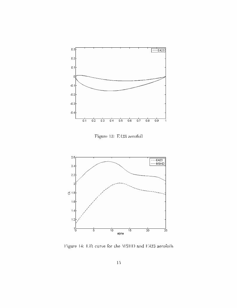
Figure 13: E423 aerofoil
Figure 14: Lift curve for the MSHD and E423 aerofoils
15

The �rst approach to optimising the aerofoil was to make an initial guess basedon suggestions in literature ([2], [3]). To limit the complexity of the optimisation, itwas decided that an aerofoil consisting of three elements, all with the same pro�le,should be optimised, as this has historically been a successful way of generating ahigh downforce aerofoil [3]. Batch simulations were run in which di�erent parameterssuch as �ap sizes, angles and distances were varied. Due to the many variablesinvolved in such an optimisation, the number of available con�gurations grow verylarge, making for an uncomfortable analysis. In an attempt to reduce this number,the aerofoil angle of attack was �xed at an angle of ∼ 25◦ where the con�gurationswere expected to operate close to their maximum. It was learned however that thismethod causes the aerofoil Cl to be optimised for that speci�c angle of attack, whileperforming poorly for others, introducing heavy separation. A discontinuity in thelift curve was present which made it evident that some other method should be usedto optimise the aerofoil con�guration in a more e�cient manner while avoiding thisunacceptable behaviour.
This mistake from the �rst round of optimisation was remedied by taking a newapproach, limiting the �ap angles and re-running the optimisation of the other pa-rameters with the DoE tools available in ANSYS Workbench. This way the toolitself would �nd con�gurations to simulate in order to �nd su�cient informationabout where the maximum may be. The resulting aerofoil con�guration has a wideoperating range which allows the wings to work properly despite changes in angle ofattack that occur when driving around a race track.
5.2 Undertray and di�user development
The optimisation of an entire undertray for a formula-style race car is a time con-suming process with many a�ecting parameters. There are many ways to designa race car undertray that produces some downforce, and the choice mostly comesdown to packaging of the rest of the vehicle's components. An undertray with doubletunnel design seemed to �t our needs the best. It was decided that the optimisationof the tunnel pro�les should be carried out using DoE tools similar to the aerofoiloptimisation. The tunnels consists of an inlet, a throat section and a di�user. Theinlet height, and di�user height was set as parameters in the DoE optimisation. Thethroat section was de�ned with two parameters, the height at the front and rearpoints, to allow for optimisation of the tunnel inclination. The rest of the dimen-sions such as the length of the inlet, throat and di�user were �xed due to geometryand competition rule constraints. A blunt body was used to simulate blockage abovethe tunnel.
16

Figure 15: Lift curve for optimised aerofoil con�guration
The optimal solution found during the DoE optimisation of the tunnel pro�le wasused to make an initial design of the undertray with its two tunnels. This was thensimulated in absence of the main bodywork and wheels. The undertray was thenintegrated to the main body for the rest of the simulations, and a splitter was addedin the front to help streamline the �ow.
In the second design iteration the tunnels were made more narrow due to packag-ing issues that came along during development. A �at �oor section was extended infront of the added splitter to allow for mounting to the frame. This second revisionwas then simulated together with the main bodywork. The mesh cell count grewlarger than the previous case due to the added geometry, but the same mesh sizingand solver settings were used. It is di�cult to assess the performance of the under-tray as one would have to compare the downforce of the entire body with undertrayto just the body without it.
It was observed that the proximity of the wheels in�uenced the air�ow negatively,especially in the rearmost part of the tunnels, and in the �nal iteration a few verticalseparating walls were added in an attempt to keep the �ow clean. Undoubtedly thedevelopment of the undertray could be taken further, but the optimisations involvedare intricate and there are many options to consider. Further development was thus
17

Figure 16: Aerofoil con�guration from DoE optimisation
Figure 17: Undertray tunnel geometry with blunt body
18

Figure 18: First revision of the undertray
19

Figure 19: Second revision. Narrower di�user tunnels and the added splitter andmounting section
20

Figure 20: Final design with separation walls in the di�user section
excluded from this project.
5.3 Wing simulation
To design the front wing for maximum downforce, the desire was to make it as largeas the rules would allow while investigating the angle of attack and the clearanceto the ground. The CFD simulations of the entire vehicle are very time-consuminghowever, and in order to save some time it was decided that the ground clearanceshould be set at 10% of the total coord as suggested in [4], while investigating theangle of attack. Three angles around the maximum for the 2D lift curve were chosenand simulated separately. The end plates at the tips of the wing were designed with-out any underlying analysis, solely based on inspiration from the many AustralianFormula Student teams. The results from the simulations give limited insight into
21

Figure 21: Front wing CFD model
α CL
22 0.734524 0.774226 0.7811
Table 2: CL for di�erent angles of the front wing
the full behaviour of the front wing, but at the very least it indicates that there isa small range of angles where it can operate properly, and it shows that the perfor-mance is increasing up until at least an angle of 26◦, as with the aerofoil in the 2Dcase. For the remainder of the simulations with the addition of the rear wing, thefront wing was held at an angle of attack of 26◦.
When the front wing simulations were completed it was time to put the rearwing in place. The process was tainted by mesh generation di�culties and timeconstraints, so the amount of simulations that could be run was limited. The wingwas designed to be as large as possible, positioned over the rear wheels, and thesimulations would then tell if the set-up needed to be adjusted to achieve the desiredload distribution. Two simulations were run, one with an inlet air velocity at 17 m/sand another at 34 m/s to see how the load distribution changes at di�erent velocitiesaround the track. The center of pressure from all the aerodynamic forces acting onthe vehicle was extracted from FLUENT and the load distribution derived from itin both cases.
While only slightly, it can be seen that the load is transferred forward at highervelocities, which indicates that the front wing works better than the rear wing,and seems to operate well in ground proximity. The desire was to have an even
22

Figure 22: Complete CFD model with rear wing
Velocity [m/s] Load distribution, Front - Rear17 58.1% - 41.9%34 59.6% - 40.4%
Table 3: Load distribution on tyres at di�erent velocities
distribution between the front and rear tyres. It may be possible to modify the rearwing to produce more downforce to even out the balance, but as it was designed to bepractically as big as possible, one may �nd better solutions by looking at adjustingthe front wing. In these simulations, the front wing angle of attack was set to it'sexpected maximum of 26◦, as mentioned. This may not be desirable as the anglemight increase momentarily during heavy braking before corners. If the angle ofattack increases too much, leading to a separation, all downforce in the front will belost, and the grip in the front tyres would be very poor when heading into the corner.This would obviously be bad for the performance of the vehicle in terms of gettingaround the track as quickly as possible, and it may be dangerous for the driver. Forthese reasons it should be better to reduce the angle of attack of the front wing, eventhough it will produce less downforce in total, to achieve the load distribution thatis sought after. Another bene�t to this approach is that the blockage from the frontwing of the cooling system at the sides of the driver will be less severe. Ultimately,�nal tuning of the vehicle's balance is best done during the testing stages where onecan use an experienced driver as a sensor to receive feedback on what changes and�ne-tuning needs to be made.
23

6 Acknowledgements
I would like to thank my supervisor Stefan Wallin for sharing his invaluable experi-ence and guidance through the course of this project. I would also like to thankJonathan Zerihan, Maximillian Tomac, and Scott Wordley for their informationabout their previous projects in the �eld. Lastly, thanks to Gustav Amberg forletting me choose this subject for my thesis.
24

References
[1] S. S. Pakkam, High Downforce Aerodynamics for Motorsports. Raleigh, NorthCarolina, 2011.
[2] S. McBeath, Competition Car Downforce, Haynes Publishers, 1998.
[3] R. H. Bernard, Road Vehicle Aerodynamic Design, MechAero Publishing, 2ndedition, 2001.
[4] J. Katz, Race Car Aerodynamics, Bentley Publishers, 1995.
[5] S. Wordley, J. Saunders, Aerodynamics for Formula SAE: Initial Design and
Performance Prediction, SAE Paper 2006-01-0806, 2006.
[6] S. Wordley, J. Saunders, Aerodynamics for Formula SAE: A Numerical, Wind
Tunnel and On-Track Study, SAE Paper 2006-01-0808, 2006.
[7] SAE, 2014 Formula SAE Rules, Society of Automotive Engineers, 2005.http://students.sae.org/cds/formulaseries/rules/
[8] X. Zhang, J. Zerihan, Aerodynamics of a Double Element Wing in Ground E�ect,AIAA Journal, Vol. 41, No. 6, pp 1007-1016, 2003.
[9] D. Case, Formula SAE: Competition History 1981-2004, Society of AutomotiveEngineers, 2005.
[10] UIUC Airfoil Coordinates Database,http://aerospace.illinois.edu/m-selig/ads/coord_database.html
[11] M. Lanfrit, Best practice guidelines for handling Automotive External Aerody-
namics with FLUENT, Fluent Deutschland GmbH, 2005.
25
Related Documents