Hello and welcome to this training module for the STM32WB Liquid Crystal Display (LCD) controller. This controller can be used in a wide range of applications such as home appliances, medical, automotive, industrial… to display either images made up of a large number of pixels, a combination of alphanumeric symbols or various useful predefined symbols such as digits, bells, low-battery symbol, arrows, antenna, and progress bar. 1

Welcome message from author
This document is posted to help you gain knowledge. Please leave a comment to let me know what you think about it! Share it to your friends and learn new things together.
Transcript
Hello and welcome to this training module for the STM32WB Liquid Crystal Display (LCD) controller. This controller can be used in a wide range of applications such as home appliances, medical, automotive, industrial… to display either images made up of a large number of pixels, a combination of alphanumeric symbols or various useful predefined symbols such as digits, bells, low-battery symbol, arrows, antenna, and progress bar.
1
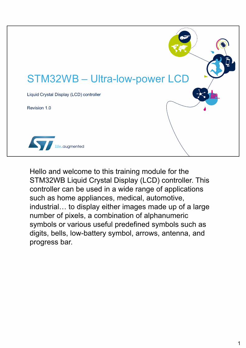
The LCD controller integrated inside STM32WB products provides a control interface for driving external segmented LCD panels. This interface is fully configurable, allowing easy control of any existing monochrome passive LCD panel (up to 320 segments) available today on the market. The STM32WB allows the LCD controller to operate in all low-power modes but it is off in Standby and Shutdown modes.Applications benefit from a built-in low-cost solution not requiring any external controller nor external analog components. The step-up converter supplying the V_LCD voltage and resistive network dedicated to generate all intermediate voltages are both part of the controller. The advantages of an embedded controller are that it does not require extra power consumption from external controllers and that it fully supports the STM32WB’s ultra-low-power modes for higher power
2
efficiency. Its flexible and high-level driving capability make it able to support a wide range of LCD displays, even those with a higher capacitive load.
2
The LCD display is made up of several segments (pixels or complete symbols) which can be made visible or invisible. Each segment consists of liquid crystal molecules aligned between 2 electrodes (1 COM terminal and 1 SEG terminal). It is equivalent to a capacitor.When a voltage greater than a threshold voltage is applied across the liquid crystal, the segment becomes visible.The waveform across a segment must alternate to avoid a DC current, otherwise the LCD’s lifetime may be shortened.
3
The LCD controller offers a fully programmable interface to control a wide range of LCD displays. The flexible frequency generator makes it easier to scale and fine tune the frame frequency. The LCD controller supports several duty ratios and bias levels to adapt to a wide range of LCD display characteristics. The structure of the resistive network is configurable by software to adapt the drive current to the LCD display used. The voltage output buffers can improve the driving capability for LCD displays with high capacitive load.
4
The LCD controller offers the option to use an internal or external V_LCD supply source to match any application constraints. With the double buffer memory, the LCD_RAM register, which contains pixel information, can be updated at any time by the application software without affecting the integrity of the data displayed. Unused segment and common pins can be used as general-purpose I/Os or for another peripheral. Last but not least, the LCD controller supports all STM32WB low-power modes, except Standby and Shutdown modes, for optimized application power efficiency.
5
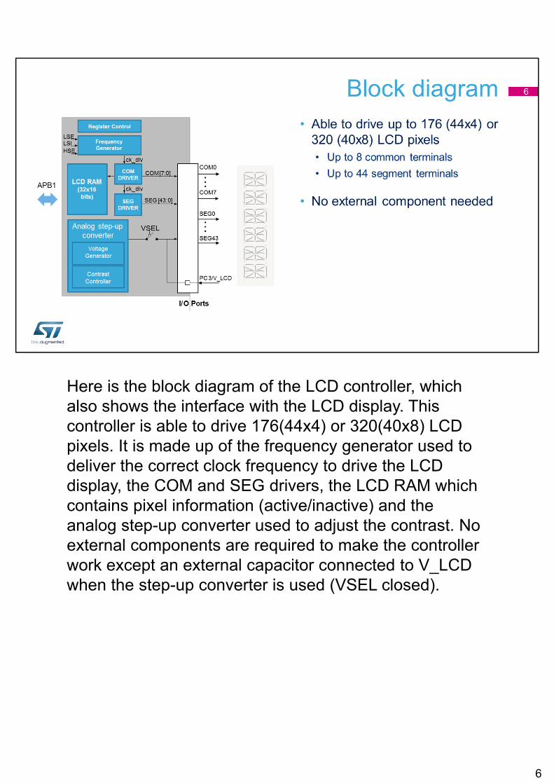
Here is the block diagram of the LCD controller, which also shows the interface with the LCD display. This controller is able to drive 176(44x4) or 320(40x8) LCD pixels. It is made up of the frequency generator used to deliver the correct clock frequency to drive the LCD display, the COM and SEG drivers, the LCD RAM which contains pixel information (active/inactive) and the analog step-up converter used to adjust the contrast. No external components are required to make the controller work except an external capacitor connected to V_LCDwhen the step-up converter is used (VSEL closed).
6
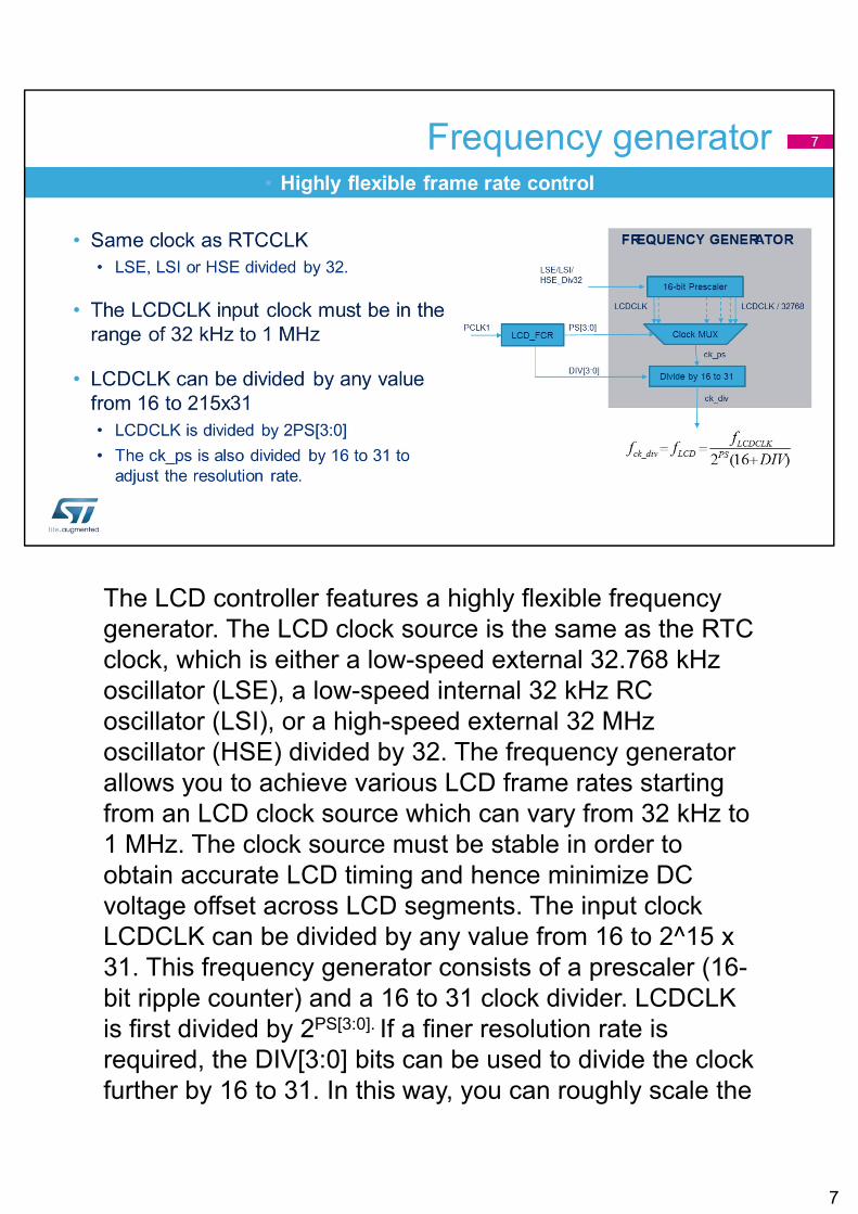
The LCD controller features a highly flexible frequency generator. The LCD clock source is the same as the RTC clock, which is either a low-speed external 32.768 kHz oscillator (LSE), a low-speed internal 32 kHz RC oscillator (LSI), or a high-speed external 32 MHz oscillator (HSE) divided by 32. The frequency generator allows you to achieve various LCD frame rates starting from an LCD clock source which can vary from 32 kHz to 1 MHz. The clock source must be stable in order to obtain accurate LCD timing and hence minimize DC voltage offset across LCD segments. The input clock LCDCLK can be divided by any value from 16 to 2^15 x 31. This frequency generator consists of a prescaler (16-bit ripple counter) and a 16 to 31 clock divider. LCDCLK is first divided by 2PS[3:0]. If a finer resolution rate is required, the DIV[3:0] bits can be used to divide the clock further by 16 to 31. In this way, you can roughly scale the
7
frequency, and then fine tune it by linearly scaling the clock with the counter. The output of the frequency generator (fck_div) constitutes the time base for the entire LCD controller. It is equivalent to the LCD phase frequency.
7
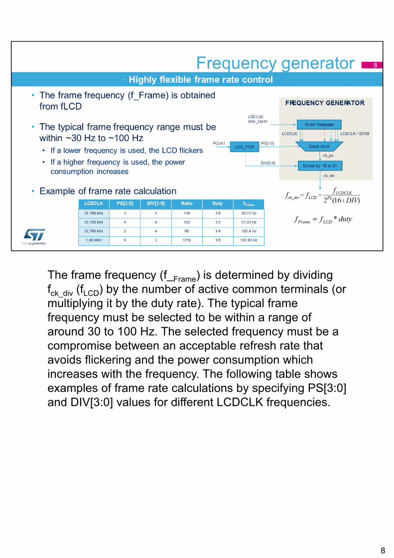
The frame frequency (f_Frame) is determined by dividing fck_div (fLCD) by the number of active common terminals (or multiplying it by the duty rate). The typical frame frequency must be selected to be within a range of around 30 to 100 Hz. The selected frequency must be a compromise between an acceptable refresh rate that avoids flickering and the power consumption which increases with the frequency. The following table shows examples of frame rate calculations by specifying PS[3:0] and DIV[3:0] values for different LCDCLK frequencies.
8
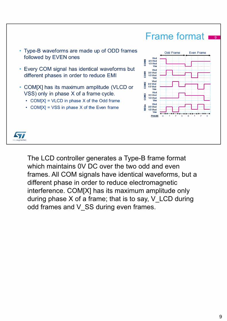
The LCD controller generates a Type-B frame format which maintains 0V DC over the two odd and even frames. All COM signals have identical waveforms, but a different phase in order to reduce electromagnetic interference. COM[X] has its maximum amplitude only during phase X of a frame; that is to say, V_LCD during odd frames and V_SS during even frames.
9
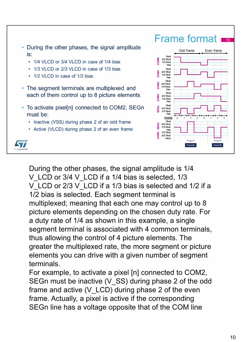
During the other phases, the signal amplitude is 1/4 V_LCD or 3/4 V_LCD if a 1/4 bias is selected, 1/3 V_LCD or 2/3 V_LCD if a 1/3 bias is selected and 1/2 if a 1/2 bias is selected. Each segment terminal is multiplexed; meaning that each one may control up to 8 picture elements depending on the chosen duty rate. For a duty rate of 1/4 as shown in this example, a single segment terminal is associated with 4 common terminals, thus allowing the control of 4 picture elements. The greater the multiplexed rate, the more segment or picture elements you can drive with a given number of segment terminals. For example, to activate a pixel [n] connected to COM2, SEGn must be inactive (V_SS) during phase 2 of the odd frame and active (V_LCD) during phase 2 of the even frame. Actually, a pixel is active if the corresponding SEGn line has a voltage opposite that of the COM line
10
(here COM2) and inactive when the voltages are equal. As a result the voltage applied between COM2 and SEGnwhich can be observed on the COM2 – SEGn waveform, is +V_LCD during phase 2 of the odd frame and –V_LCD during phase 2 of the even frame.
10
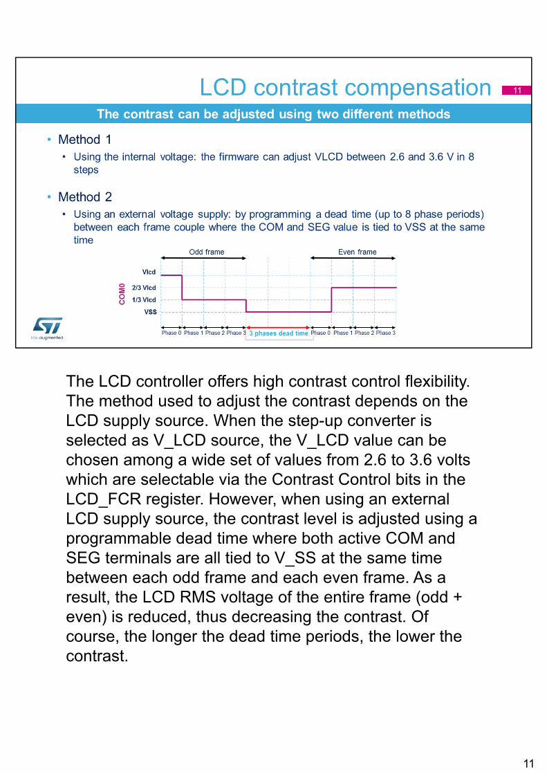
The LCD controller offers high contrast control flexibility. The method used to adjust the contrast depends on the LCD supply source. When the step-up converter is selected as V_LCD source, the V_LCD value can be chosen among a wide set of values from 2.6 to 3.6 volts which are selectable via the Contrast Control bits in the LCD_FCR register. However, when using an external LCD supply source, the contrast level is adjusted using a programmable dead time where both active COM and SEG terminals are all tied to V_SS at the same time between each odd frame and each even frame. As a result, the LCD RMS voltage of the entire frame (odd + even) is reduced, thus decreasing the contrast. Of course, the longer the dead time periods, the lower the contrast.
11
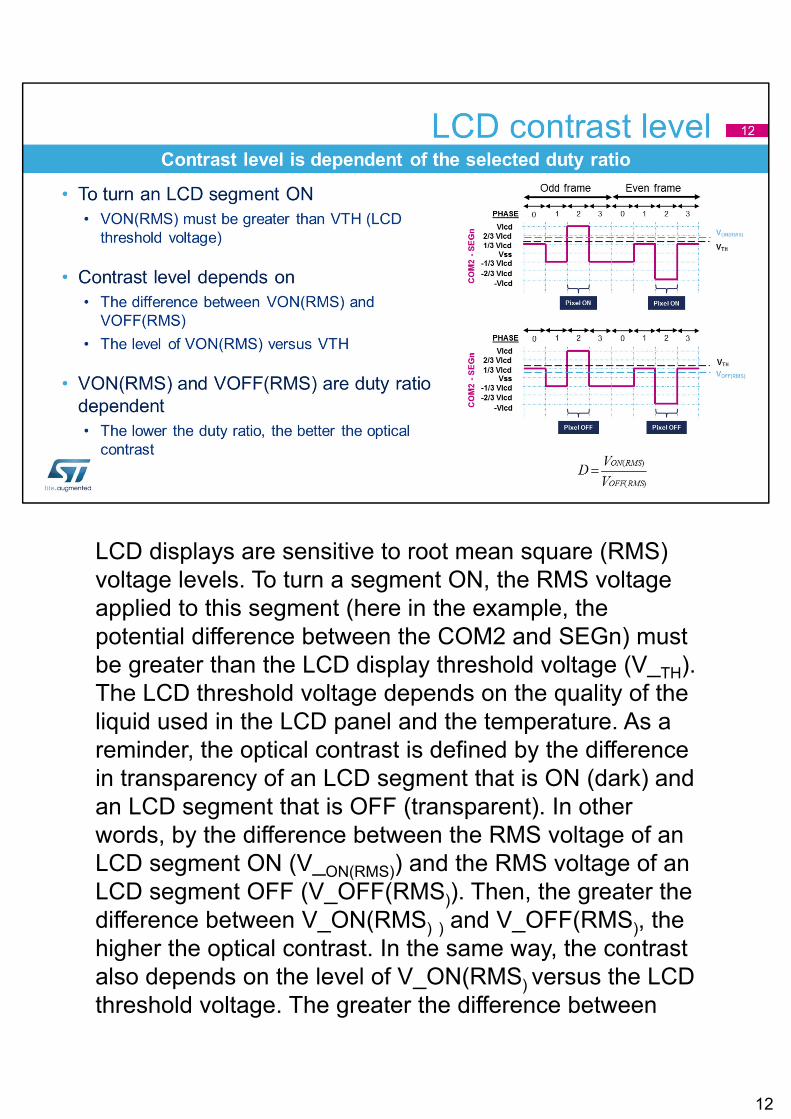
LCD displays are sensitive to root mean square (RMS) voltage levels. To turn a segment ON, the RMS voltage applied to this segment (here in the example, the potential difference between the COM2 and SEGn) must be greater than the LCD display threshold voltage (V_TH). The LCD threshold voltage depends on the quality of the liquid used in the LCD panel and the temperature. As a reminder, the optical contrast is defined by the difference in transparency of an LCD segment that is ON (dark) and an LCD segment that is OFF (transparent). In other words, by the difference between the RMS voltage of an LCD segment ON (V_ON(RMS)) and the RMS voltage of an LCD segment OFF (V_OFF(RMS)). Then, the greater the difference between V_ON(RMS) ) and V_OFF(RMS), the higher the optical contrast. In the same way, the contrast also depends on the level of V_ON(RMS) versus the LCD threshold voltage. The greater the difference between
12
V_ON(RMS) and V_TH, the higher the optical contrast.
However, V_ON(RMS) and V_OFF(RMS) are directly linked to the multiplex rate (or duty ratio) used to drive the LCD display. When the number of COM terminals required to drive the LCD display increases, the discrimination ratio (D) (contrast level that the LCD display can achieve) decreases since the separation between V_ON(RMS) and V_OFF(RMS decreases, and the contrast decreases. As a consequence, to provide a better contrast and a greater separation between V_ON(RMS) and V_OFF(RMS), when the multiplexed rate increases, the LCD voltage must be increased.Make sure the LCD controller configuration matches the LCD display needs in terms of segment and common terminals; otherwise, this could result in a lower contrast.
12
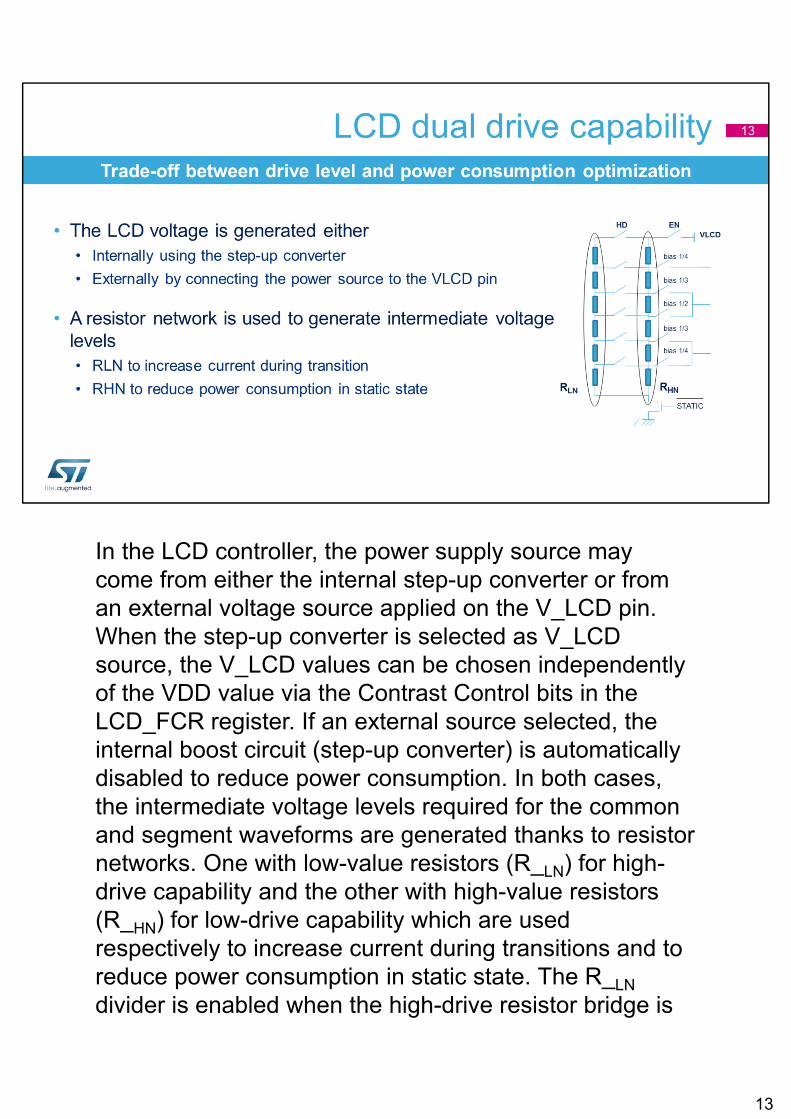
In the LCD controller, the power supply source may come from either the internal step-up converter or from an external voltage source applied on the V_LCD pin. When the step-up converter is selected as V_LCD source, the V_LCD values can be chosen independently of the VDD value via the Contrast Control bits in the LCD_FCR register. If an external source selected, the internal boost circuit (step-up converter) is automatically disabled to reduce power consumption. In both cases, the intermediate voltage levels required for the common and segment waveforms are generated thanks to resistor networks. One with low-value resistors (R_LN) for high-drive capability and the other with high-value resistors (R_HN) for low-drive capability which are used respectively to increase current during transitions and to reduce power consumption in static state. The R_LN
divider is enabled when the high-drive resistor bridge is
13
closed. The high-drive resistor bridge can be switched on permanently when HD bit is set or for only for a short period of time thanks to the Pulse On Duration (PON) feature.The PON bits configure the time during which R_LN is enabled through the HD switch each time the level of common and segment lines change.
13
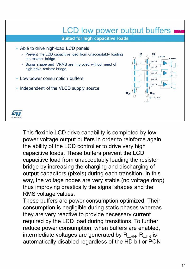
This flexible LCD drive capability is completed by low power voltage output buffers in order to reinforce again the ability of the LCD controller to drive very high capacitive loads. These buffers prevent the LCD capacitive load from unacceptably loading the resistor bridge by increasing the charging and discharging of output capacitors (pixels) during each transition. In this way, the voltage nodes are very stable (no voltage drop) thus improving drastically the signal shapes and the RMS voltage values.These buffers are power consumption optimized. Their consumption is negligible during static phases whereas they are very reactive to provide necessary current required by the LCD load during transitions. To further reduce power consumption, when buffers are enabled, intermediate voltages are generated by R_HN. R_LN is automatically disabled regardless of the HD bit or PON
14
bits configuration. Output buffers can be used regardless of the selected LCD supply source (internal or external).
14
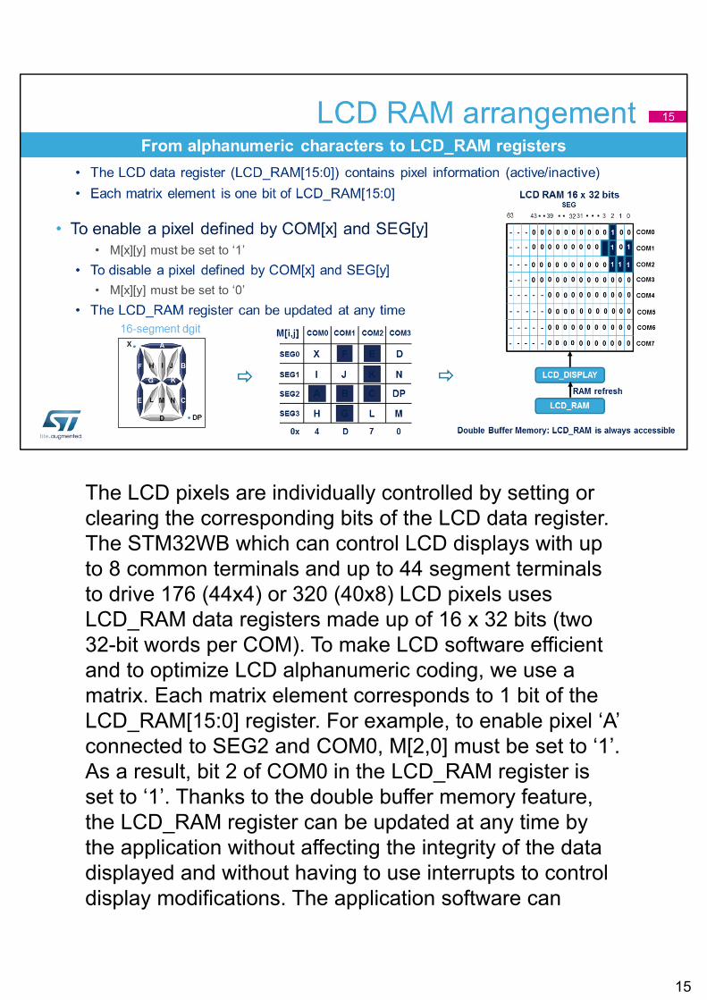
The LCD pixels are individually controlled by setting or clearing the corresponding bits of the LCD data register. The STM32WB which can control LCD displays with up to 8 common terminals and up to 44 segment terminals to drive 176 (44x4) or 320 (40x8) LCD pixels uses LCD_RAM data registers made up of 16 x 32 bits (two 32-bit words per COM). To make LCD software efficient and to optimize LCD alphanumeric coding, we use a matrix. Each matrix element corresponds to 1 bit of the LCD_RAM[15:0] register. For example, to enable pixel ‘A’ connected to SEG2 and COM0, M[2,0] must be set to ‘1’. As a result, bit 2 of COM0 in the LCD_RAM register is set to ‘1’. Thanks to the double buffer memory feature, the LCD_RAM register can be updated at any time by the application without affecting the integrity of the data displayed and without having to use interrupts to control display modifications. The application software can
15
access the first buffer level (LCD_RAM). Once its content is modified, it requests the updated information to be moved into the second buffer level (LCD_DISPLAY). This operation is done synchronously with the beginning of the next frame.
15
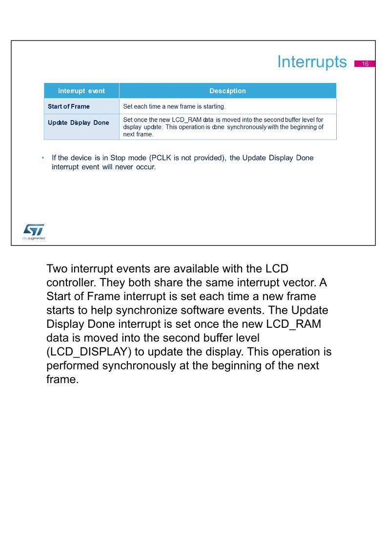
Two interrupt events are available with the LCD controller. They both share the same interrupt vector. A Start of Frame interrupt is set each time a new frame starts to help synchronize software events. The Update Display Done interrupt is set once the new LCD_RAM data is moved into the second buffer level (LCD_DISPLAY) to update the display. This operation is performed synchronously at the beginning of the next frame.
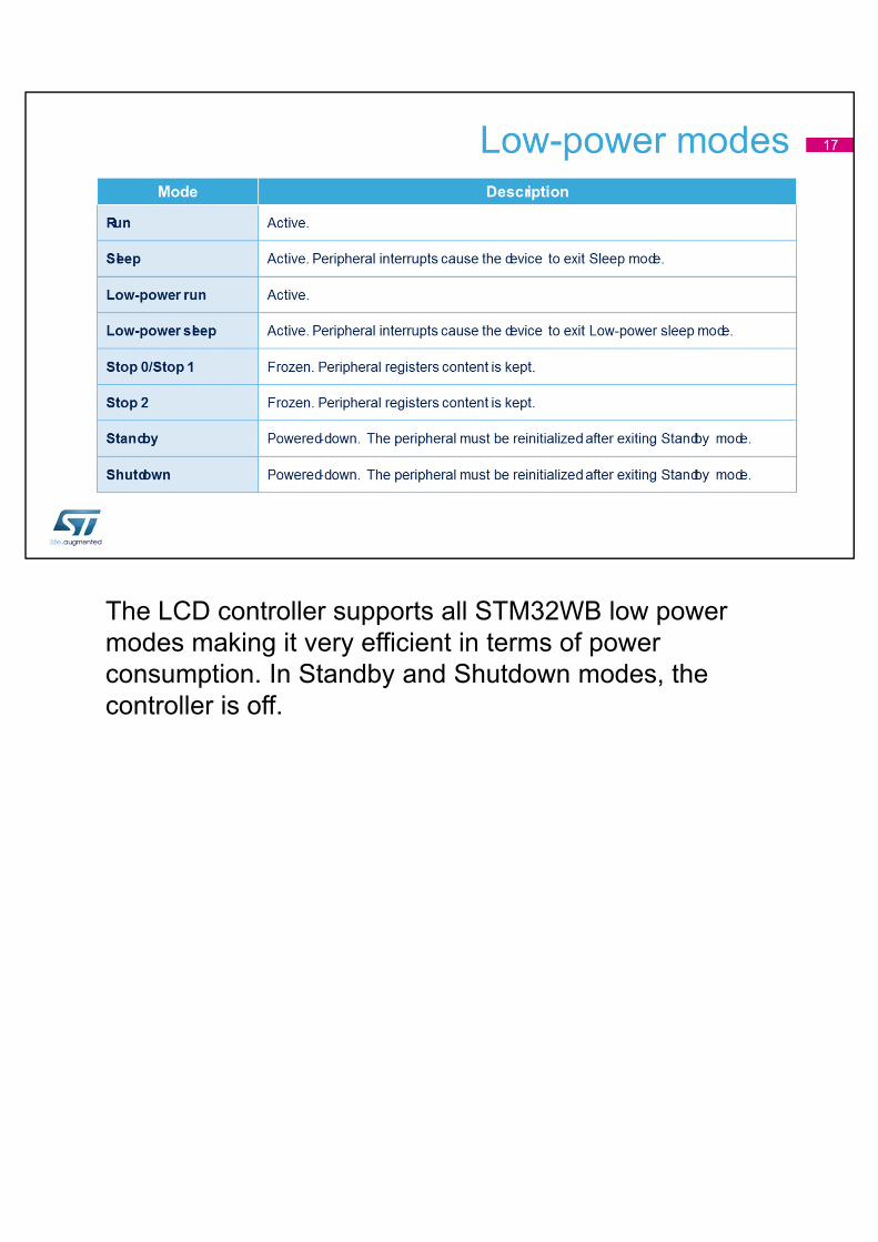
The LCD controller supports all STM32WB low power modes making it very efficient in terms of power consumption. In Standby and Shutdown modes, the controller is off.
Refer to the training modules for these peripherals linked to the LCD interface:Reset and clock controller (RCC) for more information about the LCD controller's clock sources.Interrupts for more information about the mapping of the LCD controller's interrupts.General-purpose I/Os (GPIO) for more information about the LCD controller's segment and common lines as well as the VLCD pin.Power controller (PWR) for a description of the LCD controller's low-power modes.
18
Related Documents