Helicopter Turboshafts Luke Stuyvenberg University of Colorado at Boulder Department of Aerospace Engineering The application of gas turbine engines in helicopters is discussed. The work- ings of turboshafts and the history of their use in helicopters is briefly described. Ideal cycle analyses of the Boeing 502-14 and of the General Electric T64 turboshaft engine are performed. I. Introduction to Turboshafts Turboshafts are an adaptation of gas turbine technology in which the principle output is shaft power from the expansion of hot gas through the turbine, rather than thrust from the exhaust of these gases. They have found a wide variety of applications ranging from air compression to auxiliary power generation to racing boat propulsion and more. This paper, however, will focus primarily on the application of turboshaft technology to providing main power for helicopters, to achieve extended vertical flight. II. Relationship to Turbojets As a variation of the gas turbine, turboshafts are very similar to turbojets. The operating principle is identical: atmospheric gases are ingested at the inlet, compressed, mixed with fuel and combusted, then expanded through a turbine which powers the compressor. There are two key diferences which separate turboshafts from turbojets, however. Figure 1. Basic Turboshaft Operation Note the absence of a mechanical connection between the HPT and LPT. An ideal turboshaft extracts with the HPT only the power necessary to turn the compressor, and with the LPT all remaining power from the expansion process. 1 of 10 American Institute of Aeronautics and Astronautics

Welcome message from author
This document is posted to help you gain knowledge. Please leave a comment to let me know what you think about it! Share it to your friends and learn new things together.
Transcript
Helicopter Turboshafts
Luke Stuyvenberg
University of Colorado at Boulder
Department of Aerospace Engineering
The application of gas turbine engines in helicopters is discussed. The work-ings of turboshafts and the history of their use in helicopters is briefly described.Ideal cycle analyses of the Boeing 502-14 and of the General Electric T64 turboshaftengine are performed.
I. Introduction to Turboshafts
Turboshafts are an adaptation of gas turbine technology in which the principle output is shaftpower from the expansion of hot gas through the turbine, rather than thrust from the exhaustof these gases. They have found a wide variety of applications ranging from air compression toauxiliary power generation to racing boat propulsion and more. This paper, however, will focusprimarily on the application of turboshaft technology to providing main power for helicopters, toachieve extended vertical flight.
II. Relationship to Turbojets
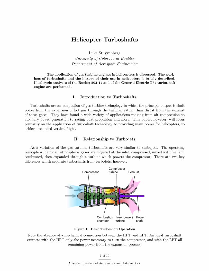
As a variation of the gas turbine, turboshafts are very similar to turbojets. The operatingprinciple is identical: atmospheric gases are ingested at the inlet, compressed, mixed with fuel andcombusted, then expanded through a turbine which powers the compressor. There are two keydiferences which separate turboshafts from turbojets, however.
Figure 1. Basic Turboshaft Operation
Note the absence of a mechanical connection between the HPT and LPT. An ideal turboshaftextracts with the HPT only the power necessary to turn the compressor, and with the LPT all
remaining power from the expansion process.
1 of 10
American Institute of Aeronautics and Astronautics
A. Emphasis on Shaft Power
Unlike turbojets, the primary purpose of which is to produce thrust from the expanded gases,turboshafts are intended to extract shaft horsepower (shp). This emphasis, in fact, leads to a desirein a maximally-efficient turboshaft engine to minimize what becomes known as ‘residual thrust’.In a turboshaft engine, the turbine is usually split into two sections. The first, the high pressureturbine (HPT), is used to drive the compressor, closing the thermodynamic ‘loop’. The second, low-pressure section of the turbine (low pressure turbine (LPT)) is usually mechanically disconnectedfrom the first, and is thus referred to as a ‘free power turbine’. Just as the HPT provides shaftpower to the compressor, it is this section that provides the output shaft power.
B. Gear Reduction
As a direct result of the shaft power focus, turboshaft engines are very often required to usea transmission gearbox to exchange the shaft’s rotational velocity for torque. For instance, whilethe free power turbine (FPT) might rotate at over 3,000 RPM, helicopter blades tend to rotate atspeeds between 300 and 400 RPM. This reduction, possibly as high as or higher than a ratio of 10:1,unavoidably requires a heavy transmission. However, unlike their turboprop cousins, turboshafttransmissions can often be connected to the structure, rather than requiring the engine itself tobear the load of a propeller.
Recent helicopter designs have included electromagnetic transmissions,1 which can greatly re-duce the mechanical wear, and perhaps failure rate,2 of previously mechanical transmissions.
III. Turboshaft Applications
Although this paper will focus on the application of turboshafts to vertical flight, turboshaftshave found a wide variety of applications worth briefly mentioning.
A. Aircraft
Besides their use powering helicopters, turboshafts are also employed on most airliners as auxil-iary power units (APUs), where they power electrical generators to ensure the aircraft can continueto function when the main engines have been damaged.
B. Ground Vehicles
Turboshaft engines have also been used to drive ground vehicles, ranging from the MTT TurbineSuperbike (powered by the Rolls-Royce 250-C18: 320 shp at 52,000 RPM) to the American M1Abrams main battle tank (powered by the Honeywell AGT1500: 1,500 shp at 2865 RPM).3
C. Marine
Some high-performance racing boats use turboshaft engines for power. Often these are adaptedfrom military surplus; the General Electric T53, T55, and T58a are especially popular. (Theseproduce anywhere from 1250 shp to 1870 shp.)4
aInterestingly, the GE T58 was among the first turbines certified for use in civilian helicopters. Now retired fromthat use, surplus units find a home in hobbyists’ racing boats.
2 of 10
American Institute of Aeronautics and Astronautics
D. Other
Some other applications of turboshaft engines beyond powering transportation include gener-ating electrical power (as in aircraft APUs), and as high-performance fluid pumps (often used bypetroleum companies in a process known as hydraulic fracturing).5
IV. Helicopter History
Most sources suggest the idea for vertical flight stems from the synthesis of a Chinese toy – atwo-bladed propeller extending from a shaft, spun between the hands and released – and Leonardoda Vinci’s sketch of a ‘flying screw’. Da Vinci provided the idea: vertical flight carrying individuals;while the toy provided the feasible rotor.6 Arguably the next most important step was taken byMikhail Lomonosov, who produced a spring-powered coaxial model with counter-rotating blades,solving the torque-balancing issue.
However, inventors pursuing these early designs quickly found that propulsion was a significantissue. The external-combustion steam engine technology of the mid- to late-1700’s could not bemade both light enough and powerful enough to lift a significant payload. Attemps of the mid-1800’s were focused on reducing the helicopter’s weight – Gustave de Ponton d’Amecourt produceda prototype in 1861 made of aluminium, but was unable to lift off.
Seventeen years later, in 1878, Italian inventor Enriko Forlanini produced a steam-poweredunmanned model which successfully lifted off. This was followed by numerous models from otherinventors – Thomas Edison’s failed attempt at using an internal combustion engine in 1885, GustaveTrouve’s tethered electric model in 1887, and Jan Bahyl”s successful internal combustion model in1905.
From then on, development proceeded more rapidly: French brothers Jacques and Lois Breguetsucceeded in manned (but tethered) flight in 1907; Paul Cornu succeeded in untethered pilotedflight later that same year; Jacob Ellehammer built a prototype with coaxial counter-rotating discsin 1912. Between 1920 and 1930, records were slowly established using internal combustion modelhelicopters, increasing maximum payload and flight duration steadily, improving controls. In 1942,the Sikorsky R-4 became the first helicopter model to enter full production.
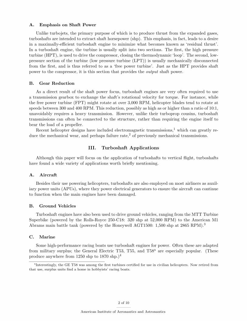
Finally, in 1951, Charles Kaman retrofitted a K-225 Synchrocopter with a Boeing 502 turboshaftengine, becoming the first turbine-powered helicopter. In 1954, a Navy HTK-1 was fitted with twoturbines to provide additional power and engine redundancy. In 1955, the French company SudAviation developed the Aerospatiale Alouette II, the first helicopter designed with a turboshaftengine in mind – the Turbomeca Artouste IIC6 turboshaft. This marked the beginning of a newage of helicopter design, making use of the light, high-power gas turbine engines to power the driveshaft for the main roter – a turboshaft.
3 of 10
American Institute of Aeronautics and Astronautics
Figure 2. K-225 w/ Boeing 502 Turboshaft
Windsor Locks, CT; piloted by William Murray. 10 December 1951. Image via Flickr underCC-BY-SA.
V. Helicopter Applications
Since their inception, helicopters have found uses wherever landing space is in short supply.Standing military forces of nations around the world often employ helicopters where an airstripcan’t be located, where terrain might prohibit the take-off or landing of fixed-wing aircraft. Thesehelicopters might serve cargo operations, carrying both supplies and personnel between locations;or they may be armed, acting as aerial support for forces on the ground, providing cover in tightlocations that fixed-wing aircraft would be unable to reach.
The private sector, too, has need of the vertical take-off and landing capabilities of helicopters:some hospitals, for example, use helicopters as ambulances, ferrying the sick or injured from loca-tions difficult to reach by ground. Oil companies invested in offshore drilling usually use helicoptersto transport workers to the drilling platforms. Construction companies often use helicopters as‘aerial cranes,’ lifting heavy equipment into otherwise-inaccessible locations. Some law enforce-ment agencies use helicopters to pursue fleeing criminals.
4 of 10
American Institute of Aeronautics and Astronautics
VI. Engine Analyses
A. Boeing 502-14
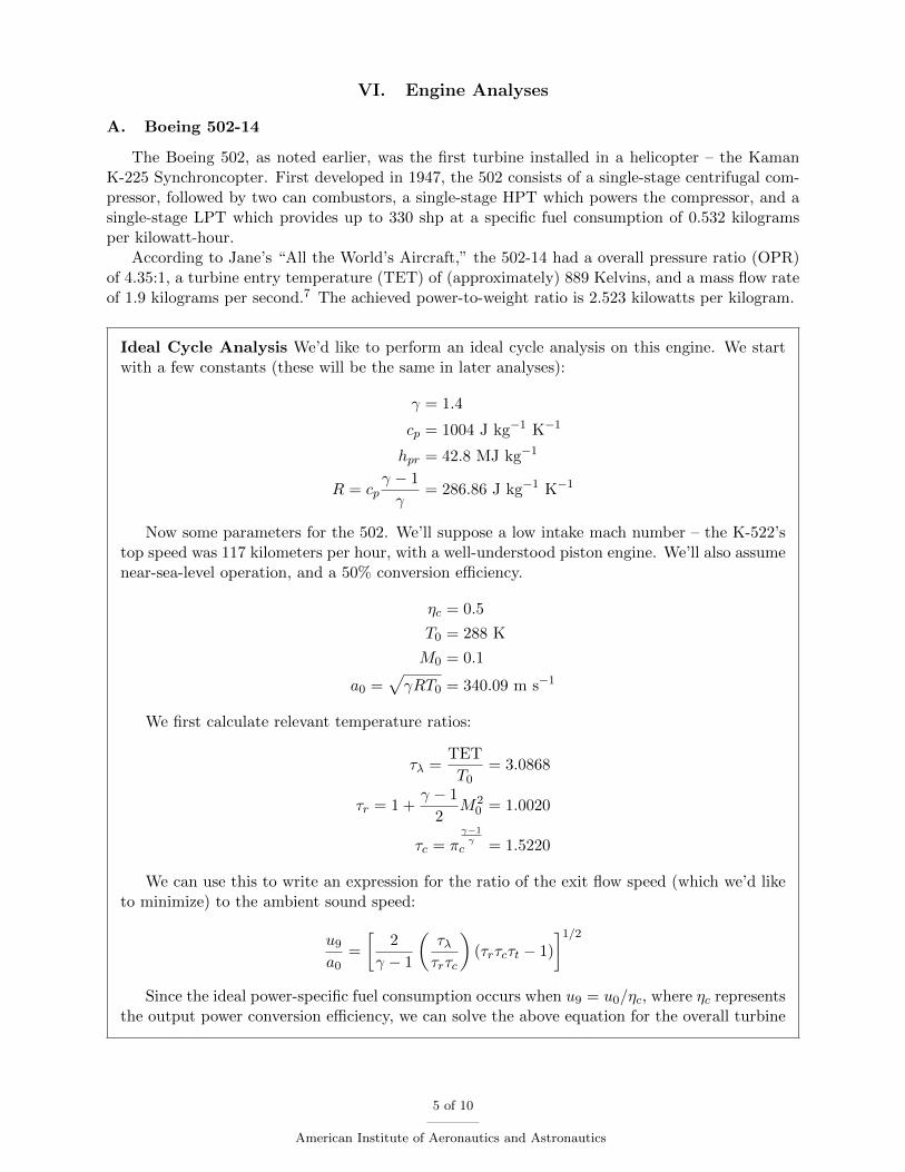
The Boeing 502, as noted earlier, was the first turbine installed in a helicopter – the KamanK-225 Synchroncopter. First developed in 1947, the 502 consists of a single-stage centrifugal com-pressor, followed by two can combustors, a single-stage HPT which powers the compressor, and asingle-stage LPT which provides up to 330 shp at a specific fuel consumption of 0.532 kilogramsper kilowatt-hour.
According to Jane’s “All the World’s Aircraft,” the 502-14 had a overall pressure ratio (OPR)of 4.35:1, a turbine entry temperature (TET) of (approximately) 889 Kelvins, and a mass flow rateof 1.9 kilograms per second.7 The achieved power-to-weight ratio is 2.523 kilowatts per kilogram.
Ideal Cycle Analysis We’d like to perform an ideal cycle analysis on this engine. We startwith a few constants (these will be the same in later analyses):
γ = 1.4
cp = 1004 J kg−1 K−1
hpr = 42.8 MJ kg−1
R = cpγ − 1
γ= 286.86 J kg−1 K−1
Now some parameters for the 502. We’ll suppose a low intake mach number – the K-522’stop speed was 117 kilometers per hour, with a well-understood piston engine. We’ll also assumenear-sea-level operation, and a 50% conversion efficiency.
ηc = 0.5
T0 = 288 K
M0 = 0.1
a0 =√γRT0 = 340.09 m s−1
We first calculate relevant temperature ratios:
τλ =TET
T0= 3.0868
τr = 1 +γ − 1
2M2
0 = 1.0020
τc = πγ−1γ
c = 1.5220
We can use this to write an expression for the ratio of the exit flow speed (which we’d liketo minimize) to the ambient sound speed:
u9a0
=
[2
γ − 1
(τλτrτc
)(τrτcτt − 1)
]1/2Since the ideal power-specific fuel consumption occurs when u9 = u0/ηc, where ηc represents
the output power conversion efficiency, we can solve the above equation for the overall turbine
5 of 10
American Institute of Aeronautics and Astronautics
temperature ratio:
u0ηca0
=
[2
γ − 1
(τλτrτc
)(τrτcτt − 1)
]1/2M2
0
η2c
γ − 1
2
τrτcτλ
= τrτcτt − 1
τt =1
τrτc+
(γ − 1)M20
2τλη2c= 0.65829
u9a0
= 0.2
Knowing that the power across the HPT must equal the power required to drive the com-pressor,
τtH = 1 − τrτλ
(τc − 1) = 0.83054
we can calculate the LPT temperature ratio
τtL =τtτtH
= 0.79261
Returning to the exit flow velocity ratio, we can calculate the core stream specific thrust:
Fcm0
= a0
(u9a0
−M0
)= a0
([2
γ − 1
(τλτrτc
)(τrτcτt − 1)
]1/2−M0
)= 34.009 m s−1
We then write the specific power as
SP =Fcu0mc
+ηcP
mc=Fca0M0
mc+ cpT0τλτtH(1 − τtL)ηc = 78.027 kW (kg s−1)−1
which gives a total shaft power
P = SP × m0 = 148 kW
Since the enthalpy balance over the combustor is unchanged from a turbojet,
f =cpT0hpr
(τλ − τrτc) = 0.010551
and so we can write the power-specific fuel consumption
SPfc =f
SP= 135.2 mg s−1 kW−1
As expected for ideal cycle analysis, the estimated power-specific fuel consumption is con-siderably lower than the rated value, even at ‘cruise’ conditions. Likewise the predicted poweroutput is much lower than the stated value.
6 of 10
American Institute of Aeronautics and Astronautics
B. General Electric T64
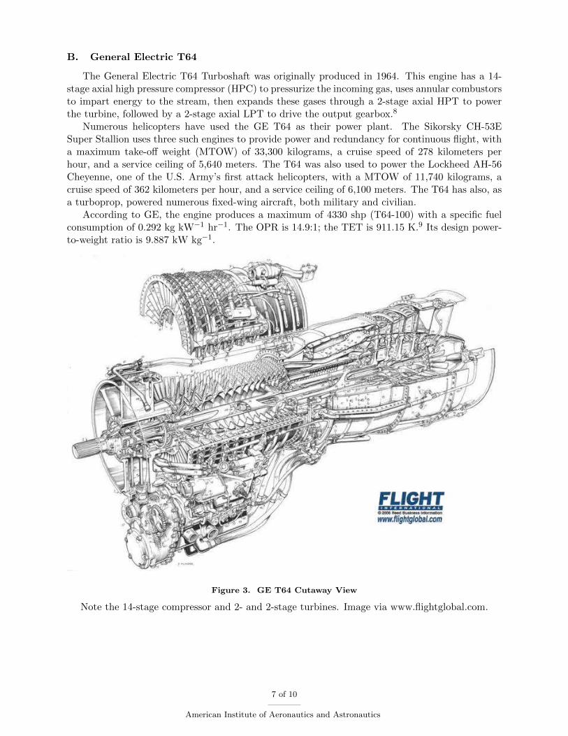
The General Electric T64 Turboshaft was originally produced in 1964. This engine has a 14-stage axial high pressure compressor (HPC) to pressurize the incoming gas, uses annular combustorsto impart energy to the stream, then expands these gases through a 2-stage axial HPT to powerthe turbine, followed by a 2-stage axial LPT to drive the output gearbox.8
Numerous helicopters have used the GE T64 as their power plant. The Sikorsky CH-53ESuper Stallion uses three such engines to provide power and redundancy for continuous flight, witha maximum take-off weight (MTOW) of 33,300 kilograms, a cruise speed of 278 kilometers perhour, and a service ceiling of 5,640 meters. The T64 was also used to power the Lockheed AH-56Cheyenne, one of the U.S. Army’s first attack helicopters, with a MTOW of 11,740 kilograms, acruise speed of 362 kilometers per hour, and a service ceiling of 6,100 meters. The T64 has also, asa turboprop, powered numerous fixed-wing aircraft, both military and civilian.
According to GE, the engine produces a maximum of 4330 shp (T64-100) with a specific fuelconsumption of 0.292 kg kW−1 hr−1. The OPR is 14.9:1; the TET is 911.15 K.9 Its design power-to-weight ratio is 9.887 kW kg−1.
Figure 3. GE T64 Cutaway View
Note the 14-stage compressor and 2- and 2-stage turbines. Image via www.flightglobal.com.
7 of 10
American Institute of Aeronautics and Astronautics
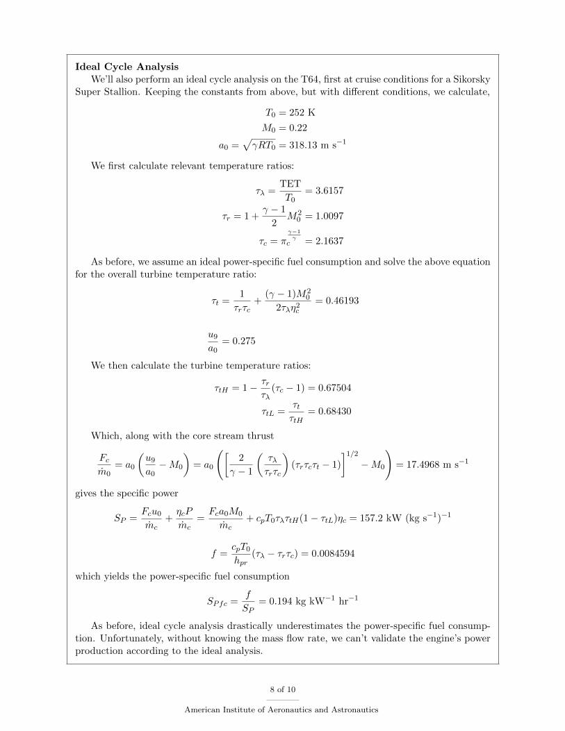
Ideal Cycle AnalysisWe’ll also perform an ideal cycle analysis on the T64, first at cruise conditions for a Sikorsky
Super Stallion. Keeping the constants from above, but with different conditions, we calculate,
T0 = 252 K
M0 = 0.22
a0 =√γRT0 = 318.13 m s−1
We first calculate relevant temperature ratios:
τλ =TET
T0= 3.6157
τr = 1 +γ − 1
2M2
0 = 1.0097
τc = πγ−1γ
c = 2.1637
As before, we assume an ideal power-specific fuel consumption and solve the above equationfor the overall turbine temperature ratio:
τt =1
τrτc+
(γ − 1)M20
2τλη2c= 0.46193
u9a0
= 0.275
We then calculate the turbine temperature ratios:
τtH = 1 − τrτλ
(τc − 1) = 0.67504
τtL =τtτtH
= 0.68430
Which, along with the core stream thrust
Fcm0
= a0
(u9a0
−M0
)= a0
([2
γ − 1
(τλτrτc
)(τrτcτt − 1)
]1/2−M0
)= 17.4968 m s−1
gives the specific power
SP =Fcu0mc
+ηcP
mc=Fca0M0
mc+ cpT0τλτtH(1 − τtL)ηc = 157.2 kW (kg s−1)−1
f =cpT0hpr
(τλ − τrτc) = 0.0084594
which yields the power-specific fuel consumption
SPfc =f
SP= 0.194 kg kW−1 hr−1
As before, ideal cycle analysis drastically underestimates the power-specific fuel consump-tion. Unfortunately, without knowing the mass flow rate, we can’t validate the engine’s powerproduction according to the ideal analysis.
8 of 10
American Institute of Aeronautics and Astronautics
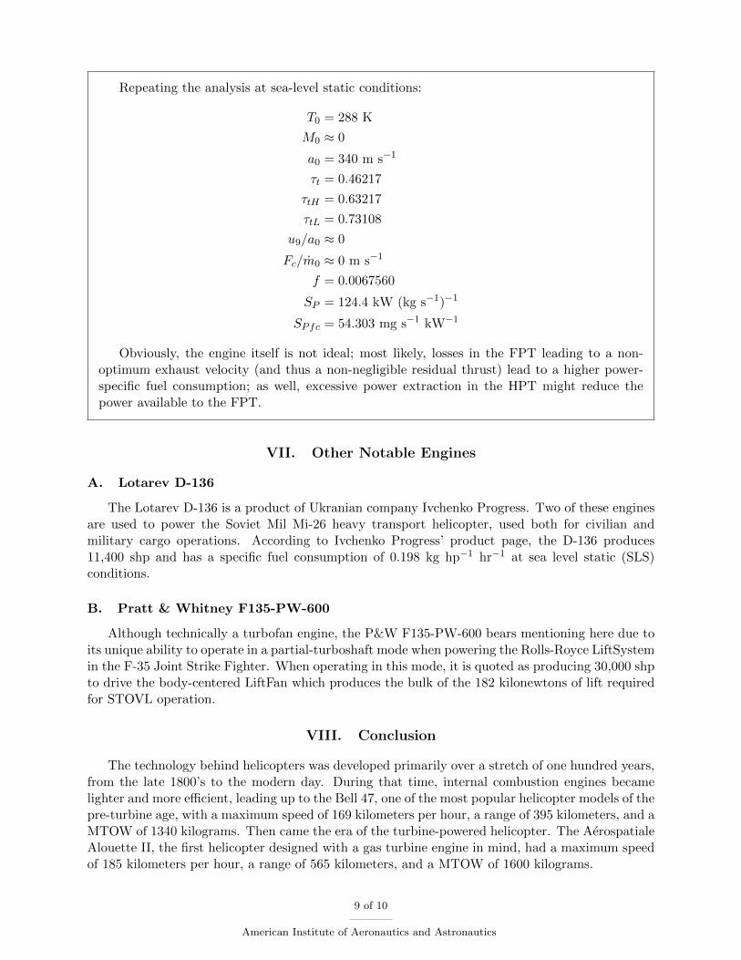
Repeating the analysis at sea-level static conditions:
T0 = 288 K
M0 ≈ 0
a0 = 340 m s−1
τt = 0.46217
τtH = 0.63217
τtL = 0.73108
u9/a0 ≈ 0
Fc/m0 ≈ 0 m s−1
f = 0.0067560
SP = 124.4 kW (kg s−1)−1
SPfc = 54.303 mg s−1 kW−1
Obviously, the engine itself is not ideal; most likely, losses in the FPT leading to a non-optimum exhaust velocity (and thus a non-negligible residual thrust) lead to a higher power-specific fuel consumption; as well, excessive power extraction in the HPT might reduce thepower available to the FPT.
VII. Other Notable Engines
A. Lotarev D-136
The Lotarev D-136 is a product of Ukranian company Ivchenko Progress. Two of these enginesare used to power the Soviet Mil Mi-26 heavy transport helicopter, used both for civilian andmilitary cargo operations. According to Ivchenko Progress’ product page, the D-136 produces11,400 shp and has a specific fuel consumption of 0.198 kg hp−1 hr−1 at sea level static (SLS)conditions.
B. Pratt & Whitney F135-PW-600
Although technically a turbofan engine, the P&W F135-PW-600 bears mentioning here due toits unique ability to operate in a partial-turboshaft mode when powering the Rolls-Royce LiftSystemin the F-35 Joint Strike Fighter. When operating in this mode, it is quoted as producing 30,000 shpto drive the body-centered LiftFan which produces the bulk of the 182 kilonewtons of lift requiredfor STOVL operation.
VIII. Conclusion
The technology behind helicopters was developed primarily over a stretch of one hundred years,from the late 1800’s to the modern day. During that time, internal combustion engines becamelighter and more efficient, leading up to the Bell 47, one of the most popular helicopter models of thepre-turbine age, with a maximum speed of 169 kilometers per hour, a range of 395 kilometers, and aMTOW of 1340 kilograms. Then came the era of the turbine-powered helicopter. The AerospatialeAlouette II, the first helicopter designed with a gas turbine engine in mind, had a maximum speedof 185 kilometers per hour, a range of 565 kilometers, and a MTOW of 1600 kilograms.
9 of 10
American Institute of Aeronautics and Astronautics
Certainly, other advancements in materials and engineering during this ten year design gapmay have contributed to this dramatic performance increase, but nevertheless, turboshaft engineshave proliferated in the years since, and presently only the lightest of manned helicopters are stillpowered by internal combustion engines.
References
1Andrew, A. F. et al., “Helicopter flight control system,” March 30 1965, US Patent 3,175,786.2“Annual Safety Review,” 2011.3Colucci, F., “Heavy duty: overhaul underway for Abrams tank engine,” 2006.4Walsh, P. P. and Fletcher, P., Gas turbine performance, John Wiley & Sons, 2004.5Crom, E., “Pump system for high pressure applications,” May 22 2014, WO Patent App. PCT/US2013/069,463.6Johnson, W., Helicopter Theory , Dover Books on Aeronautical Engineering, Dover Publications, 2012.7Taylor, J. W. R. and Jane, F. T., Jane’s All the World’s Aircraft, 1965-66 , McGraw-Hill Book Company, 1965.8Aviation Week, Aerospace Source Book 2009 , Aviation Week & Space Technology, 2009.9Leyes, R. and Fleming, W., The History of North American Small Gas Turbine Aircraft Engines, Library of
Flight, AIAA, 1999.
Glossary
APU auxiliary power unit.
FPT free power turbine.
HPC high pressure compressor.
HPT high pressure turbine.
LPT low pressure turbine.
MTOW maximum take-off weight.
OPR overall pressure ratio.
shp shaft horsepower.
SLS sea level static.
TET turbine entry temperature.
10 of 10
American Institute of Aeronautics and Astronautics
Related Documents