CIVIL AVIATION AUTHORITY OF MALAYSIA HELICOPTER OFFSHORE OPERATIONS CIVIL AVIATION GUIDANCE MATERIAL – 6008 (VII) ISSUE 01 REVISION 00 – 17 TH DECEMBER 2021 HOFO

Welcome message from author
This document is posted to help you gain knowledge. Please leave a comment to let me know what you think about it! Share it to your friends and learn new things together.
Transcript
CIVIL AVIATION AUTHORITY OF MALAYSIA
HELICOPTER OFFSHORE
OPERATIONS
CIVIL AVIATION GUIDANCE MATERIAL – 6008 (VII)
ISSUE 01 REVISION 00 – 17TH DECEMBER 2021
HOFO

INTENTIONALLY LEFT BLANK

Introduction
Issue 01/Rev 00 CAGM 6008 (VII) – HOFO 3
IntroductionThis Civil Aviation Guidance Material 6008 Part III (CAGM – 6008 (VII)) is issued by the Civil Aviation Authority of Malaysia (CAAM) to provide guidance for the application for, and approval for Helicopter Offshore Operations (HOFO), pursuant to Civil Aviation Directives 6 Part 3 - Helicopters (collectively referred to as “CAD”).
Organisations may use these guidelines to ensure compliance with the respective provisions of the relevant CADs issued. Notwithstanding the Regulation 204 and Regulation 205 of the Malaysian Civil Aviation Regulations 2016 (MCAR) 2016, when the CAGMs issued by the CAAM are complied with, the related requirements of the CAD’s may be deemed as being satisfied and further demonstration of compliance may not be required.
(Captain Chester Voo Chee Soon) Chief Executive Officer
Civil Aviation Authority of Malaysia
Introduction
Issue 01/Rev 00 CAGM 6008 (VII) – HOFO 4
Civil Aviation Guidance Material components and Editorial practices This Civil Aviation Guidance Material is made up of the following components and are defined as follows: Standards: Usually preceded by words such as “shall” or “must”, are any specification for physical characteristics, configuration, performance, personnel or procedure, where uniform application is necessary for the safety or regularity of air navigation and to which Operators must conform. In the event of impossibility of compliance, notification to the CAAM is compulsory. Recommended Practices: Usually preceded by the words such as “should” or “may”, are any specification for physical characteristics, configuration, performance, personnel or procedure, where the uniform application is desirable in the interest of safety, regularity or efficiency of air navigation, and to which Operators will endeavour to conform. Appendices: Material grouped separately for convenience but forms part of the Standards and Recommended Practices stipulated by the CAAM. Definitions: Terms used in the Standards and Recommended Practices which are not self-explanatory in that they do not have accepted dictionary meanings. A definition does not have an independent status but is an essential part of each Standard and Recommended Practice in which the term is used, since a change in the meaning of the term would affect the specification. Tables and Figures: These add to or illustrate a Standard or Recommended Practice and which are referred to therein, form part of the associated Standard or Recommended Practice and have the same status. Notes: Included in the text, where appropriate, Notes give factual information or references bearing on the Standards or Recommended Practices in question but not constituting part of the Standards or Recommended Practices; Attachments: Material supplementary to the Standards and Recommended Practices or included as a guide to their application.
The units of measurement used in this document are in accordance with the International System of Units (SI) as specified in CAD 5. Where CAD 5 permits the use of non-SI alternative units, these are shown in parentheses following the basic units. Where two sets of units are quoted it must not be assumed that the pairs of values are equal and interchangeable. It may, however, be inferred that an equivalent level of safety is achieved when either set of units is used exclusively. Any reference to a portion of this document, which is identified by a number and/or title, includes all subdivisions of that portion. Throughout this Civil Aviation Guidance Material, the use of the male gender should be understood to include male and female persons.
Record of Revisions
Issue 01/Rev 00 CAGM 6008 (VII) – HOFO 5
Record of Revisions Revisions to this CAGM shall be made by authorised personnel only. After inserting the revision, enter the required data in the revision sheet below. The ‘Initials’ has to be signed off by the personnel responsible for the change.
Rev No. Revision Date Revision Details Initials

Record of Revisions
Issue 01/Rev 00 CAGM 6008 (VII) – HOFO 6
INTENTIONALLY LEFT BLANK
Summary of Changes
Issue 01/Rev 00 CAGM 6008 (VII) – HOFO 7
Summary of Changes
ISS/REV no. Item no. Revision Details

Summary of Changes
Issue 01/Rev 00 CAGM 6008 (VII) – HOFO 8
INTENTIONALLY LEFT BLANK
Table of Content
Issue 01/Rev 00 CAGM 6008 (VII) – HOFO 9
Table of Content
1 GENERAL .............................................................................................................................................. 1-1
1.1 BACKGROUND ........................................................................................................................................ 1-1 1.2 DEFINITIONS .......................................................................................................................................... 1-1 1.3 ABBREVIATIONS ...................................................................................................................................... 1-6
2 OPERATING PROCEDURES .................................................................................................................... 2-1
2.1 SAFETY MANAGEMENT ............................................................................................................................. 2-1 2.2 FLIGHT OPERATION .................................................................................................................................. 2-1 2.3 USE OF OFFSHORE LOCATION ..................................................................................................................... 2-3 2.4 SELECTION OF AERODROME AND OPERATING SITES ......................................................................................... 2-9 2.5 AIRBORNE RADAR APPROACH (ARA) TO OFFSHORE LOCATION ....................................................................... 2-11 2.6 HELICOPTER PERFORMANCE .................................................................................................................... 2-17 2.7 FLIGHT DATA MONITORING SYSTEM ......................................................................................................... 2-17 2.8 AIRCRAFT TRACKING SYSTEM ................................................................................................................... 2-28 2.9 VIBRATION HEALTH MONITORING (VHM) SYSTEM ..................................................................................... 2-28 2.10 ADDITIONAL EQUIPMENT REQUIREMENT .................................................................................................... 2-29 2.11 ADDITIONAL PROCEDURES REQUIREMENT ................................................................................................... 2-31 2.12 FLIGHT CREW TRAINING AND CHECKING ..................................................................................................... 2-31
3 ATTACHMENTS ..................................................................................................................................... 3-1
3.1 ATTACHMENT A – COMPLIANCE DOCUMENTS FOR HELICOPTER OPERATION ACCORDANCE WITH CAGM 6008 (VII) -
HOFO. APPROVAL FOR HELICOPTER OFFSHORE OPERATIONS ....................................................................................... 3-1 3.2 ATTACHMENT B – OPERATIONS DOCUMENTATION REVIEW ............................................................................ 3-9

Table of Content
Issue 01/Rev 00 CAGM 6008 (VII) – HOFO 10
INTENTIONALLY LEFT BLANK
Chapter 1 – General
Issue 01/Rev 00 CAGM 6008 (VII) – HOFO 1-1
1 General
1.1 Background
Helicopter offshore operation or HOFO is defined by ICAO as an operation by a helicopter for the purpose of:
a) support of offshore oil, gas and mineral exploration, production, storage andtransport;
b) support to offshore wind turbines and other renewable-energy sources; or
c) support to ships including sea pilot transfer.
which comprised of equipment and procedures for flight crew to support flight operations or duties.
This CAGM provides the guidance to understand the intent and objectives of the requirements for the performance of operational evaluation and its commonly used functions; and, where appropriate, enables the operator to seek operational approval from CAAM.
1.2 Definitions
Aerodrome means any area of land or water, including any airport, airstrip (including water airstrip), heliport, building, installation and equipment, for the use wholly or partly for the arrival, departure or movement of aircraft.
Aerodrome certificate means a certificate issued by the appropriate authority under applicable regulations for the operation of an aerodrome
Aerodrome identification sign means a sign placed on an aerodrome to aid in identifying the aerodrome from the air.
Airport means the aggregate of the lands comprised within an aerodrome including building, aircraft hangers, storage, facilities, road and car parks used or intended to be used in whole or in part for the purposes of or in connection with the operation of such aerodrome.
Airworthiness inspector (AWI) is a representative of the Civil Aviation Authority of Malaysia in charge of initial authorisation and/or continued oversight of the operator’s maintenance and engineering organisation and processes. The assessment performed by the AWI may include (but not be limited to):
a) the adequacy of maintenance facilities, equipment and procedures;
b) the adequacy of the training programmes and competence of employees;
c) the adequacy of the programme or schedule for periodic maintenance andoverhauls; and
d) the airworthiness of the aircraft.
Certified aerodrome means an aerodrome whose operator has been granted an aerodrome certificate.
Chapter 1 – General
Issue 01/Rev 00 CAGM 6008 (VII) – HOFO 1-2
D means the largest overall dimension of the helicopter when rotor(s) are turning measured from the most forward position of the main rotor tip path plane to the most rearward position of the tail rotor tip path plane or helicopter structure.
D-value means a limiting dimension, in terms of “D”, for a heliport, helideck or shipboard
heliport, or for a defined area within.
Declared distances — heliports.
a) Take-off distance available (TODAH). The length of the FATO plus the length of helicopter clearway (if provided) declared available and suitable for helicopters to complete the take-off.
b) Rejected take-off distance available (RTODAH). The length of the FATO declared available and suitable for helicopters operated in performance class 1 to complete a rejected take-off.
c) Landing distance available (LDAH). The length of the FATO plus any additional area declared available and suitable for helicopters to complete the landing manoeuvre from a defined height.
Design D means the D of the design helicopter
D-value means a limiting dimension, in terms of “D”, for a heliport, helideck or shipboard heliport, or for a defined area within.
Declared distances — heliports.
a) Take-off distance available (TODAH). The length of the FATO plus the length of helicopter clearway (if provided) declared available and suitable for helicopters to complete the take-off.
b) Rejected take-off distance available (RTODAH). The length of the FATO declared available and suitable for helicopters operated in performance class 1 to complete a rejected take-off.
c) Landing distance available (LDAH). The length of the FATO plus any additional area declared available and suitable for helicopters to complete the landing manoeuvre from a defined height.
Dynamic load-bearing surface means a surface capable of supporting the loads generated by a helicopter in motion.
Flight operations inspector (FOI) Is a representative of the Civil Aviation Authority of Malaysia in charge of initial authorisation and/or continued oversight of the operator’s flight operations organisation and processes. The assessment performed by the FOI may include (but not be limited to):
a) the adequacy of flight operations facilities, equipment and procedures;
b) the adequacy of the training programmes and competence of employees; and
c) the adequacy of the programme to ensure safe operations of the aircraft.
Chapter 1 – General
Issue 01/Rev 00 CAGM 6008 (VII) – HOFO 1-3
Heliport means an aerodrome or a defined area on a structure intended to be used wholly or in part for the arrival, departure and surface movement of helicopters.
Helicopter clearway means a defined area on the ground or water, selected and/or prepared as a suitable area over which a helicopter operated in performance class 1 may accelerate and achieve a specific height.
Helicopter stand means an aircraft stands which provides for parking a helicopter and where ground taxi operations are completed or where the helicopter touches down and lifts off for air taxi operations.
Helicopter taxiway means a defined path on a heliport intended for the ground movement of helicopters and that may be combined with an air taxi-route to permit both ground and air taxiing.
Helicopter taxi-route means a defined path established for the movement of helicopters from one part of a heliport to another.
a) Air taxi-route. A marked taxi-route intended for air taxiing.
b) Ground taxi-route. A taxi-route centred on a taxiway.
Helideck means a heliport located on a fixed or floating offshore facility such as an exploration and/or production unit used for the exploitation of oil or gas.
The term ‘helideck’ includes take-off and landing operations on ships and vessels and covers ‘shipboard final approach and take off areas (FATOs).
Helicopter landing officer is a designated person on duty at an off-shore installation responsible for supporting safe helicopter operations to the helideck and the daily supervision of the helideck.
Helideck radio operator is a designated person responsible for ensuring effective radio communications between helicopter flight crew and the helideck.
Heliport elevation is the elevation of the highest point of the FATO.
Heliport reference point (HRP) is the designated location of a heliport or a landing location.
Hostile environment means an environment in which:
a) a safe forced landing cannot be accomplished because the surface and surrounding environment are inadequate; or
b) the helicopter occupants cannot be adequately protected from the elements; or
c) search and rescue response/capability is not provided consistent with anticipated exposure; or
d) there is an unacceptable risk of endangering persons or property on the ground.
Instrument runway means one of the following types of runways intended for the operation of aircraft using instrument approach procedures:
a) Non-precision approach runway. A runway served by visual aids and non-visual aid(s) intended for landing operations following an instrument approach operation type A and a visibility not less than 1 000 m.
Chapter 1 – General
Issue 01/Rev 00 CAGM 6008 (VII) – HOFO 1-4
b) Precision approach runway, category I. A runway served by visual aids and nonvisual aid(s) intended for landing operations following an instrument approach operation type B with a decision height (DH) not lower than 60 m (200 ft) and either a visibility not less than 800 m or a runway visual range not less than 550 m.
c) Precision approach runway, category II. A runway served by visual aids and nonvisual aid(s) intended for landing operations following an instrument approach operation type B with a decision height (DH) lower than 60 m (200 ft) but not lower than 30 m (100 ft) and a runway visual range not less than 300 m.
d) Precision approach runway, category III. A runway served by visual aids and non-visual aid(s) intended for landing operations following an instrument approach operation type B with a decision height (DH) lower than 30 m (100 ft), or no decision height and a runway visual range less than 300 m, or no runway visual range limitations.
Note 1.— Visual aids need not necessarily be matched to the scale of non-visual aids provided. The criterion for the selection of visual aids is the conditions in which operations are intended to be conducted.
Note 2.— Refer to CAD 6 — Operation of Aircraft for instrument approach operation types.
Land includes land covered with water and any right in or over land.
Landing area means that part of a movement area intended for the landing or take-off of aircraft.
Normally Unmanned Installation (fixed helideck) is an offshore installation designed to be primarily operated remotely, without the constant presence of personnel.
Obstacle means all fixed (whether temporary or permanent) and mobile objects, or parts thereof, that:
a) are located on an area intended for the surface movement of aircraft; or
b) extend above a defined surface intended to protect aircraft in flight; or
c) stand outside those defined surfaces and that have been assessed as being a hazard to air navigation
Offshore location means a location or destination on a fixed or floating offshore structure or vessel, and includes helidecks, helicopter hoist operations areas and operating sites.
Offshore location includes, but is not limited to:
a) helidecks;
b) shipboard heliports; and
Chapter 1 – General
Issue 01/Rev 00 CAGM 6008 (VII) – HOFO 1-5
c) winching areas on vessels or renewable-energy installations.
Offshore operation means a helicopter operation that has a substantial proportion of any flight conducted over open sea areas to or from an offshore location;
Point-in-space approach (Pins) is the Point-in-space approach is based on GNSS and is an approach procedure designed for helicopter only. It is aligned with a reference point located to permit subsequent flight manoeuvring or approach and landing using visual manoeuvring in adequate visual conditions to see and avoid obstacles.
Point-in-space (Pins) visual segment is the segment of a helicopter Pins approach procedure from the Map to the landing location for a Pins “proceed visually” procedure. This visual segment connects the Point-in-space (Pins) to the landing location.
Note. — The procedure design criteria for a Pins approach and the detailed design requirements for a visual segment are established in the ICAO Procedures for Air Navigation Services — Aircraft Operations, (PANS-OPS, Doc 8168).
Protection area is a defined area surrounding a stand intended to reduce the risk of damage from helicopters accidentally diverging from the stand.
Rejected take-off area is a defined area on a heliport suitable for helicopters operating in performance class 1 to complete a rejected take-off.
Runway-type FATO is a FATO having characteristics similar in shape to a runway.
Safety area means a defined area on a heliport surrounding the FATO which is free of obstacles, other than those required for air navigation purposes, and intended to reduce the risk of damage to helicopters accidentally diverging from the FATO.
Shipboard heliport means a heliport located on a ship that may be purpose or non-purpose-built. A purpose-built shipboard heliport is one designed specifically for helicopter operations. A non-purpose-built shipboard heliport is one that utilises an area of the ship that is capable of supporting a helicopter but not designed specifically for that task.
Static load-bearing surface means a surface capable of supporting the mass of a helicopter situated upon it.
Surface-level heliport means a heliport located on the ground or on a structure on the surface of the water.
Touchdown and lift-off area (TLOF) means an area on which a helicopter may touch down or lift off.
Chapter 1 – General
Issue 01/Rev 00 CAGM 6008 (VII) – HOFO 1-6
1.3 Abbreviations
ACAS = Airborne Collision Avoidance System
AFCS = Automatic Flight Control Systems
AIP = Aeronautical Information Publication
ALT = Altitude
AMMD = Aircraft Moving Map Display
AMSL = Above Mean Sea Level
AOC = Air Operator Certificate
AODB = Airport, Runway, Obstacle Database
APU = Auxiliary Power Unit
ARA = Airborne Radar Approach
ATC = Air Traffic Control
ATS = Air Traffic Services
CAA = Civil Aviation Authority
CAAM = Civil Aviation Authority of Malaysia
CAD = Civil Aviation Directive
CAGM = Civil Aviation Guidance Materials
CEO = Chief Executive Officer
DFO = Director of Flight Operations
DH = Decision Height
DIFFS = Deck Integrated Firefighting System
DME = Distance Measuring Equipment
EGPWS = Enhance Ground Proximity Warning System
ELT = Emergency Locator Transmitter
FAF = Final Approach Fix
FAP = Final Approach Point
FATO = Final Approach and Take-off Area
FDM = Flight Data Monitoring
FFSs - Full Flight Simulators
FOI = Flight Operations Inspector
FPSO = Floating Production Storage and Offloading
Chapter 1 – General
Issue 01/Rev 00 CAGM 6008 (VII) – HOFO 1-7
FRF = Final Reserve Fuel
ft = Foot
GPS = Global Positioning System
GPU = Ground Power Unit
HIALS = High Intensity Approach Lighting System
HLL = Helideck Limitation List
HLO = Helicopter Landing Officer
HRG = Helideck Route Guide
HTWAS = Helicopter Terrain Awareness System
Hz = Hertz
ICAO = International Civil Aviation Organisation
IGE = In Ground Effect
IFR = Instrument Flight Rules
INS = Inertial Navigation Systems
IMC = Instrument Meteorological Conditions
Kg = Kilogram
KIAS = Knot Indicated Air Speed
Km/h = Kilometre Per Hour
MAPt = Missed Approach Point
MCAR = Civil Aviation Regulations 2016
MDA = Minimum Descent Altitude
MDH = Minimum Descent Height
MEL = Minimum Equipment List
MMEL = Master Minimum Equipment List
MTOM = Maximum Take-off Mass
NOTAM = Notice to Airmen
OEI = One Engine Inoperative
OGE = Out of Ground Effect
OIP = Offset Initiation Point
PED = Portable Electronic Device
PPE = Personal Protective Equipment
RNAV = Area Navigation
Chapter 1 – General
Issue 01/Rev 00 CAGM 6008 (VII) – HOFO 1-8
RNP = Required Navigation Performance
RNP APCH = Required Navigation Performance Approach
RWY = Runway
SARPs = Standards and Recommended Practices
SMS = Safety Management System
SOA = Safety Oversight Audit
SOP = Standard Operating Procedure
SPA = Specific Approval
TACS = Taxi Aid Camera System
TCH = Type Certificate Holder
TCAS = Traffic Collision Avoidance System
TOM = Takeoff Mass
UTC = Universal Time Coordinated
VFR = Visual Flight Rules
VOR = Very High-Frequency Omnidirectional Radio Range
VSS = Visual Segment Surface
Chapter 2 – Operating Procedures
Issue 01/Rev 00 CAGM 6008 (VII) – HOFO 2-1
2 Operating Procedures
2.1 Safety management
The operator shall, as part of its safety management process, mitigate and minimise risks and hazards specific to helicopter offshore operations. The operator shall specify in the operations manual the:
a) selection, composition and training of crews;
b) duties and responsibilities of crew members and other involved personnel;
c) required equipment and dispatch criteria; and
d) operating procedures and minima, such that normal and likely abnormal operations are described and adequately mitigated.
The operator shall conduct the risk assessment which should include but not limited to the following hazards:
a) collision with offshore installations, vessels and floating structures;
b) collision with wind turbines;
c) collision with skysails;
d) collision during low-level instrument meteorological conditions (IMC) operations;
e) collision with obstacles adjacent to helidecks;
f) collision with surface/water;
g) IMC or night offshore approaches;
h) loss of control during operations to small or moving offshore locations;
i) operations to unattended helidecks;
j) weather and/or sea conditions that could either cause an accident or exacerbate its consequences
k) landing at a wrong deck;
l) landing without LG down and lock
2.2 Flight operation
The operator shall ensure that an operational flight plan is prepared prior to each flight. The operational flight plan should contain at least the items listed in CAD 6 PART 3 (2.3.3) Operational Flight Planning.
Where established, the offshore route structure provided by the appropriate ATS is need to be followed. This is also need to be in accordance with any restriction
Chapter 2 – Operating Procedures
Issue 01/Rev 00 CAGM 6008 (VII) – HOFO 2-2
on the routes or the areas of operation specified by the competent authority or the appropriate authority responsible for the airspace.
Passenger Safety Briefing shall be conducted before every boarding. It should include every safety aspect applicable to the helicopter in this relevant operation. The briefing should be presented and demonstrated to the passengers by audio-visual electronic means (video, DVD or similar), or the passengers should be informed about them by a crew member prior to boarding the aircraft.
Briefing items shall include;
a) the use of the life jackets and where they are stowed if not in use;
b) the proper use of coverall (offshore workwear), including briefing on the need to have suits fully zipped with, if applicable, hoods and gloves on, during take-off and landing or when otherwise advised by the pilot-in-command/commander;
c) the proper use of emergency breathing equipment;
d) the location and operation of the emergency exits;
e) life raft deployment and boarding; deployment of all survival equipment; and boarding and disembarkation instructions.
When operating in a hostile environment, the operator may add any other elements that considered relevant to be briefed.
Pilots must optimize the use of the automatic flight control systems (AFCS) throughout the flight.
However, in order to ensure flight crew competency in manual handling of the helicopter, the operator should provide instructions to the flight crew in the operations manual under which circumstances the helicopter may be operated in lower modes of automation. Emphasis should be given to flight in instrument meteorological conditions (IMC) and instrument approaches.
A documentation on specific offshore approach profiles, including stable approach parameters and the corrective action to be taken if an approach becomes unstable need to be established by the operator in the Operation Manual.
An operator is required to setup a comprehensive procedure for multi-pilot operations, procedures are in place for a member of the flight crew to monitor the flight instruments during an offshore flight, especially during approach or departure. This also to include crew immediate and appropriate action when a height alert is activated and to require the emergency floatation systems to be armed, when safe to do so, for all overwater arrivals and departures.
Chapter 2 – Operating Procedures
Issue 01/Rev 00 CAGM 6008 (VII) – HOFO 2-3
2.3 Use of offshore location
The operator shall only use offshore locations that are suitable in relation to size and mass of the type of helicopter and to the operations concerned. The operations manual relating to the specific usage of offshore helicopter landing areas as specified in ASD 103 which contain, or make reference to, a directory of helidecks (Helideck Route Guide (HRG)) intended to be used by the operator.
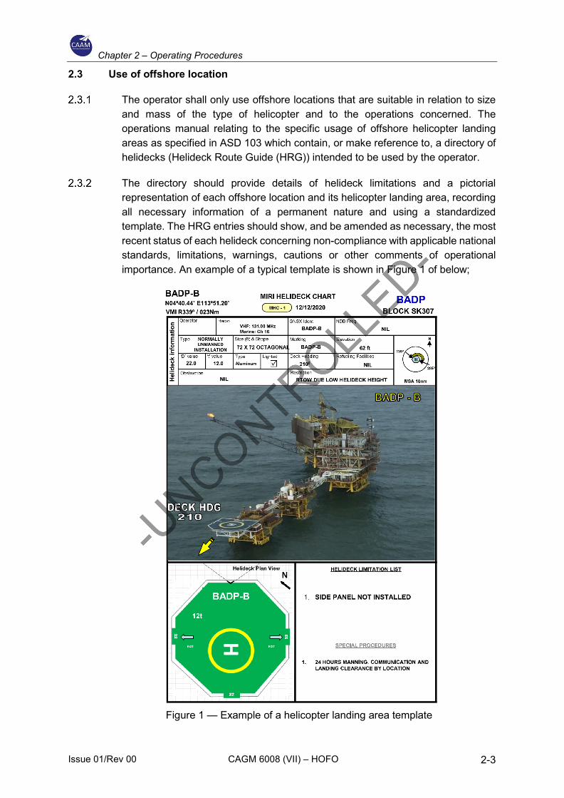
The directory should provide details of helideck limitations and a pictorial representation of each offshore location and its helicopter landing area, recording all necessary information of a permanent nature and using a standardized template. The HRG entries should show, and be amended as necessary, the most recent status of each helideck concerning non-compliance with applicable national standards, limitations, warnings, cautions or other comments of operational importance. An example of a typical template is shown in Figure 1 of below;
Figure 1 — Example of a helicopter landing area template
Chapter 2 – Operating Procedures
Issue 01/Rev 00 CAGM 6008 (VII) – HOFO 2-4
In order to ensure that the safety of flights is not compromised, the operator should obtain relevant information and details in order to compile the HRG, as well as the pictorial representation from the owner/operator of the offshore helicopter landing area.
In case of renaming an offshore location become necessary, the old name should also be included in the HRG for the following 6 months.
Any limitations associated with an offshore location should be included in the HRG. With complex installation arrangements, including combinations of installations/vessels (e.g., combined operations), a separate listing in the HRG, accompanied by diagrams/pictures, where necessary, may be required.
Each offshore helicopter landing area should be inspected and assessed based on limitations, warnings, instructions and restrictions, in order to determine its acceptability with respect to the following as a minimum:
a) Consideration The physical characteristics of the landing area, including size, load-bearing capability and the appropriate ‘D’ and ‘t’ values.
Note 1. – ‘D’ is the overall length of the helicopter from the most forward position of the main rotor tip to the most rearward position of the tail rotor tip plane path, or rearmost extension of the fuselage in the case of ‘Fenestron’ or ‘NOTAR’ tails.
Note 2. – ‘t’ is the maximum allowable mass in tonnes.
b) The preservation of obstacle-protected surfaces (an essential safeguard for all flights). These surfaces are:
1) The minimum 210° obstacle-free surface (OFS) above helideck level 2) The 150° limited-obstacle surface (LOS) above helideck level; and 3) The minimum 180° falling ‘5:1’ gradient with respect to significant
obstacles below helideck level. 4) If these sectors/surfaces are infringed, even on a temporary basis, and/or
if an adjacent installation or vessel infringes the obstacle-protected surfaces related to the landing area, an assessment should be made to determine whether it is necessary to impose operating limitations and/or restrictions to mitigate any non-compliance with the criteria.
c) Marking and lighting:
1) For operations at night, adequate illumination of the perimeter of the landing area, using perimeter lighting that meets national requirements;
2) For operations at night, adequate illumination of the location of the touchdown marking by use of a lit touchdown/positioning marking and lit helideck identification marking that meet national requirements;
3) Status lights (for night and day operations, indicating the status of the helicopter landing area, e.g. a red flashing light indicates ‘landing area unsafe: do not land’) meeting national requirements;
Chapter 2 – Operating Procedures
Issue 01/Rev 00 CAGM 6008 (VII) – HOFO 2-5
4) dominant-obstacle paint schemes and lighting; 5) Condition of helideck markings; and 6) Adequacy of general installation and structure lighting.
Note. – Any limitations with respect to non-compliance of lighting arrangements may require the HRG to be annotated ‘daylight only operations.
d) Deck surface:
1) Assessment of surface friction; 2) Adequacy and condition of helideck net (where provided); 3) ‘Fit for purpose’ drainage system; 4) Deck edge safety netting or shelving; 5) A system of tie-down points that is adequate for the range of helicopters
in use; and 6) Procedures to ensure that the surface is kept clean of all contaminants,
e.g. Bird guano, sea spray, snow and ice.
e) Environment:
1) Foreign Object Damage; 2) An assessment of physical turbulence generators, e.g. structure-induced
turbulence; 3) Bird control measures; 4) Deck edge safety netting or shelving; 5) Air flow degradation due to gas turbine exhaust emissions (turbulence
and thermal effects), flares (thermal effects) or cold gas vents (unburned flammable gas); and
6) Adjacent offshore installations may need to be included in the environmental assessment.
Note. – To assess for potential adverse environmental effects, as described in (ii), (iv) and (v) above, an offshore location should be subject to appropriate studies, e.g. wind tunnel testing and/or computational fluid dynamics (CFD) analysis.
7) Rescue and Fire Fighting Systems for delivery of firefighting media to the landing area, e.g. deck integrated firefighting system (DIFFS);
8) Delivery of primary media types, assumed critical area, application rate and duration;
9) Deliveries of complementary agent(s) and media types, capacity and discharge;
10) Personal protective equipment (PPE); and 11) rescue equipment and crash box/cabinet.
f) Communication and Navigation:
1) Aeronautical radio(s); 2) Radio-telephone (R/T) call sign to match the offshore location name with
the side identification that should be simple and unique; and 3) Radio log.
Chapter 2 – Operating Procedures
Issue 01/Rev 00 CAGM 6008 (VII) – HOFO 2-6
g) Fuelling facilities: in accordance with the relevant national guidance and legislation.
h) Additional operational and handling equipment:
1) Windsock; 2) Meteorological information, including wind, pressure, air temperature,
and dew point temperature, and equipment recording and displaying mean wind (10-min wind) and gusts;
3) Helideck motion recording and reporting system, where applicable; 4) Passenger briefing system; 5) Chocks; 6) Tie-down strops/ropes; 7) Weighing scales; 8) A suitable power source for starting helicopters (e.g. ground power unit
(GPU)), where applicable; and 9) Equipment for clearing the landing area of snow, ice and other
contaminants.
i) A fully trained helicopter-landing-area staff (e.g. helicopter landing officer/helicopter deck assistant and firefighters, etc.); persons required to assess local weather conditions or communicate with the helicopter by radio-telephony should be appropriately qualified.
j) The HRG entry for each offshore location should be completed and kept up to date, using the template and reflecting the information and details described in 2.3.1 above. The template should contain at least the following details:
1) Name of offshore location; 2) R/t call sign; 3) Helicopter landing area identification marking; 4) Side panel identification marking; 5) Landing area elevation; 6) Maximum installation/vessel height; 7) Helideck size and/or ‘d’ value; 8) Type of offshore location:
i) Fixed, permanently manned installation; ii) Fixed, normally unattended installation; iii) Vessel type (e.g. Diving support vessel, tanker, etc.); iv) Semi-submersible, mobile, offshore drilling unit: v) Jack-up, mobile, offshore drilling unit: vi) Floating production storage and offloading (FPSO);
9) Name of owner/operator; 10) Geographical position, where appropriate; 11) Com/nav frequencies and identification;
Chapter 2 – Operating Procedures
Issue 01/Rev 00 CAGM 6008 (VII) – HOFO 2-7
12) General drawing of the offshore location that shows the helicopter landing area with annotations indicating location of derrick, masts, cranes, flare stack, turbine and gas exhausts, side identification panels, windsock, etc.;
13) Plan view drawing, and chart orientation from the general drawing to show the above; the plan view should also show the 210-degree sector orientation in degrees true;
14) Type of fuelling:
i) Pressure and gravity; ii) Pressure only; iii) Gravity only; and iv) None;
15) Type and nature of firefighting equipment; 16) Availability of GPU; 17) Deck heading; 18) ‘t’ value; 19) Status light system (yes/no); and 20) Revision publication date or number; and
k) Consideration one or more diagrams/photographs, and any other suitable guidance to assist pilots.
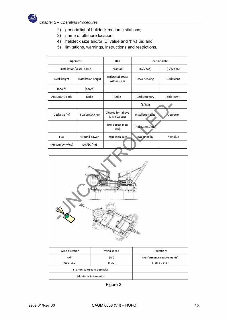
For offshore locations for which there is incomplete information, ‘restricted’ usage based on the information available may be considered by the operator, subject to risk assessment prior to the first helicopter visit. During subsequent operations, and before any restriction on usage is lifted, information should be gathered and the following should apply:
a) Pictorial (static) representation:
1) Template blanks (figure 2 is provided as an example) should be available to be filled in during flight preparation on the basis of the information given by the offshore location owner/operator and of flight crew observations;
2) Where possible, suitably annotated photographs may be used until the HRG entry and template have been completed;
3) Until the HRG entry and template have been completed, conservative operational restrictions (e.g. Performance, routing, etc.) May be applied;
4) Any previous inspection reports should be obtained and reviewed by the operator; and
5) An inspection of the offshore helicopter landing area should be carried out to verify the content of the completed HRG entry and template; once found suitable, the landing area may be considered authorised for use by the operator.
b) With reference to the above, the HRG entry should contain at least the following:
1) HRG revision date or number;
Chapter 2 – Operating Procedures
Issue 01/Rev 00 CAGM 6008 (VII) – HOFO 2-8
2) generic list of helideck motion limitations; 3) name of offshore location; 4) helideck size and/or ‘D’ value and ‘t’ value; and 5) limitations, warnings, instructions and restrictions.
Figure 2
Chapter 2 – Operating Procedures
Issue 01/Rev 00 CAGM 6008 (VII) – HOFO 2-9
2.4 Selection of aerodrome and operating sites
Operators should use available standards and regulations provided for operations to offshore locations such as those contained in CAD 6 Part 3 and ICAO Annex 14 Vol II ‘Heliports’.
Coastal Aerodrome.
a) Any alleviation from the requirement to select an alternate aerodrome for a flight to a coastal aerodrome under instrument flight rules (IFR) routing from offshore should be based on an individual safety risk assessment.
b) The following should be taken into account:
1) Suitability of the weather based on the landing forecast for the destination;
2) The fuel required to meet the IFR requirements of CAD 6 Part 3 except for the alternate fuel;
3) Where the destination coastal aerodrome is not directly on the coast, it should be:
i) Within a distance that with the fuel specified in (b)(2), the helicopter is able, at any time after crossing the coastline, to return to the coast, descend safely, carry out an approach under visual flight rules (VFR) and land, with the VFR fuel reserves intact;
ii) Within 5 nm of the coastline; and iii) Geographically sited so that the helicopter is able, within the rules of
the air and within the landing forecast, to proceed inbound from the coast at 500ft above ground level (AGL), and carry out an approach and landing under VFR; or to proceed inbound from the coast on an agreed route, and carry out an approach and landing under VFR;
c) Procedures for coastal aerodromes should be based on a landing forecast no worse than:
1) By day, a cloud base of ≥ 400 ft above descent height (DH)/minimum descent height (MDH), and a visibility of 4 km, or, if descent over the sea is intended, a cloud base of 600 ft and a visibility of 4 km; or
2) By night, a cloud base of 1 000 ft and a visibility of 5 km;
d) The descent to establish visual contact with the surface should take place over the sea or as part of the instrument approach;
e) Routings and procedures for coastal aerodromes nominated as such should be included in the operations manual.
f) The minimum equipment list (MEL) should reflect the requirement for airborne radar and radio altimeter for this type of operation; and
Chapter 2 – Operating Procedures
Issue 01/Rev 00 CAGM 6008 (VII) – HOFO 2-10
g) Operational limitations for each coastal aerodrome should be specified in the Operations Manual.
Offshore Destination Alternate Aerodrome (as refer to Helideck).
a) The landing environment at an offshore location proposed for use as an offshore destination alternate helideck should be pre-surveyed, together with the physical characteristics, such as the effect of wind direction and strength, as well as of turbulence established.
b) This information should be available to the pilot-in-command/commander both at the planning stage and in-flight, should be published in an appropriate form in the Operations Manual (including the orientation of the helideck) so that the suitability of the alternate helideck can be assessed.
c) This helideck should meet the criteria for size and obstacle clearance appropriate to the performance requirements of the type of helicopter concerned.
d) The use of an offshore destination alternate helideck should be restricted to helicopters that can achieve one engine inoperative (OEI) in ground effect (IGE) hover at an appropriate power rating above the helideck at the offshore location.
e) Where the surface of the helideck or prevailing conditions (especially wind velocity) precludes an OEI IGE, OEI out-of-ground effect (OGE) hover performance at an appropriate power rating should be used to compute the landing mass. The landing mass should be calculated based on graphs provided in the Operations Manual. When this landing mass is computed, due account should be taken of helicopter configuration, environmental conditions and the operation of systems that have an adverse effect on performance.
f) The planned landing mass of the helicopter, including crew, passengers, baggage, cargo plus 30-min final reserve fuel (FRF), should not exceed the OEI landing mass of the helicopter at the time of approach to the offshore destination alternate.
g) Weather Considerations:
1) Meteorological observations. When the use of an offshore destination alternate helideck is planned, the meteorological observations, both at the offshore destination and the alternate helideck, should be made by an observer acceptable to the authority responsible for the provision of meteorological services;
2) Weather minima. When the use of an offshore destination alternate helideck is planned, the operator should neither select an offshore location as destination nor as alternate helideck unless the weather forecasts for the two offshore locations indicate that during a period commencing 1 h before and ending 1 h after the expected time of arrival
Chapter 2 – Operating Procedures
Issue 01/Rev 00 CAGM 6008 (VII) – HOFO 2-11
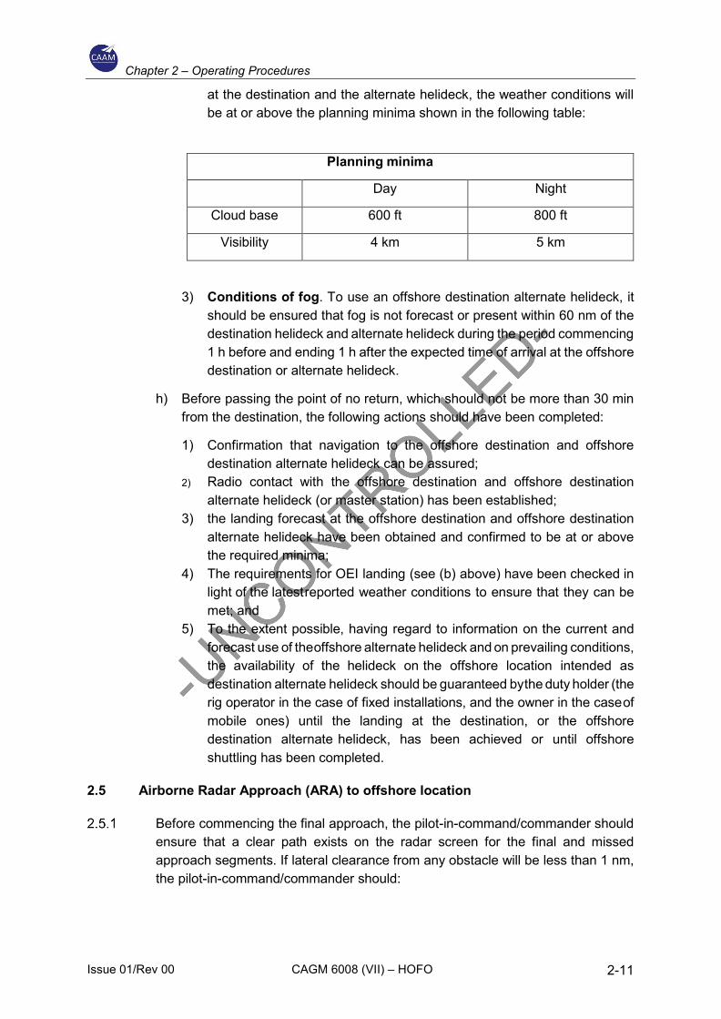
at the destination and the alternate helideck, the weather conditions will be at or above the planning minima shown in the following table:
3) Conditions of fog. To use an offshore destination alternate helideck, it
should be ensured that fog is not forecast or present within 60 nm of the destination helideck and alternate helideck during the period commencing 1 h before and ending 1 h after the expected time of arrival at the offshore destination or alternate helideck.
h) Before passing the point of no return, which should not be more than 30 min from the destination, the following actions should have been completed:
1) Confirmation that navigation to the offshore destination and offshore destination alternate helideck can be assured;
2) Radio contact with the offshore destination and offshore destination alternate helideck (or master station) has been established;
3) the landing forecast at the offshore destination and offshore destination alternate helideck have been obtained and confirmed to be at or above the required minima;
4) The requirements for OEI landing (see (b) above) have been checked in light of the latest reported weather conditions to ensure that they can be met; and
5) To the extent possible, having regard to information on the current and forecast use of the offshore alternate helideck and on prevailing conditions, the availability of the helideck on the offshore location intended as destination alternate helideck should be guaranteed by the duty holder (the rig operator in the case of fixed installations, and the owner in the case of mobile ones) until the landing at the destination, or the offshore destination alternate helideck, has been achieved or until offshore shuttling has been completed.
2.5 Airborne Radar Approach (ARA) to offshore location
Before commencing the final approach, the pilot-in-command/commander should ensure that a clear path exists on the radar screen for the final and missed approach segments. If lateral clearance from any obstacle will be less than 1 nm, the pilot-in-command/commander should:
Planning minima
Day Night
Cloud base 600 ft 800 ft
Visibility 4 km 5 km
Chapter 2 – Operating Procedures
Issue 01/Rev 00 CAGM 6008 (VII) – HOFO 2-12
a) Make an approach to a nearby target structure and thereafter proceeds visually to the destination structure;
b) Make the approach from another direction leading to a circling manoeuvre; and
c) The cloud ceiling should be sufficiently clear above the helideck to permit a safe landing.
Minimum descent height (MDH) should not be less than 50 ft above the elevation of the helideck:
a) The MDH for an airborne radar approach should not be lower than 200 ft by day; or 300 ft by night; and
b) the MDH for an approach leading to a circling manoeuvre should not be lower than 300 ft by day; or 500 ft by night.
Minimum descent altitude (MDA) may only be used if the radio altimeter is unserviceable. The MDA should be a minimum of the MDH + 200 ft, and be based on a calibrated barometer at the destination or on the lowest forecast barometric pressure adjusted to sea level (QNH) for the region.
The decision range should not be less than 0.75 nm.
For approaches to non-moving offshore locations, the maximum range discrepancy between the global position system (GPS) and the weather radar display should not be greater than 0.3 nm at any point between the final approach fix (FAF) at 5 nm from the offshore location and the offset initiation point (OIP) at 1.5 nm from the offshore location.
For approaches to non-moving offshore locations, the maximum bearing discrepancy between the GPS and the weather radar display should not be greater than 10° at the FAF at 4 nm from the offshore location.
General Procedures for ARA;
a) The helicopter ARA procedure may have as many as five separate segments: the arrival, initial, intermediate, final approach, and missed approach segment.
b) In addition, the specifications of the circling manoeuvre to a landing under visual conditions should be considered. The individual approach segments can begin and end at designated fixes. However, the segments of an ARA may often begin at specified points where no fixes are available.
c) The fixes, or points, are named to coincide with the beginning of the associated segment. For example, the intermediate segment begins at the intermediate fix (IF) and ends at the final approach fix (FAF).
Chapter 2 – Operating Procedures
Issue 01/Rev 00 CAGM 6008 (VII) – HOFO 2-13
d) Where no fix is available or appropriate, the segments begin and end at specified points; for example, at the intermediate point (IP) and final approach point (FAP).
e) The order in which the segments are discussed in this CAGM is the order in which the pilot would fly them in a complete procedure: that is, from the arrival through the initial and intermediate to the final approach and, if necessary, to the missed approach.
f) Only those segments that are required by local conditions applying at the time of the approach need to be included in a procedure.
g) In constructing the procedure, the final approach track, which should be orientated so as to be substantially into the wind, should be identified first as it is the least flexible and most critical of all the segments.
h) When the origin and the orientation of the final approach have been determined, the other necessary segments should be integrated with it to produce an orderly manoeuvring pattern that does not generate an unacceptably high workload for the flight crew.
i) Where an ARA is conducted to a non-moving offshore location (i.e. fixed installation or moored vessel), and a reliable global positioning system (GPS) position for the location is available, the GPS/area navigation system should be used to enhance the safety of the ARA.
j) This is achieved by using the GPS/area navigation system to navigate the helicopter onto, and maintain, the final approach track, and by using the GPS range and bearing information to cross-check the position of the offshore location on the weather radar display.
Obstacle Environment for ARA.
a) Each segment of the ARA is located in an overwater area that has a flat surface at sea level. However, due to the passage of large vessels which are not required to notify their presence, the exact obstacle environment cannot be determined.
b) As the largest vessels and structures are known to reach elevations exceeding 500 ft above mean sea level (AMSL), the uncontrolled offshore obstacle environment applies to the arrival, initial and intermediate approach segments can reasonably be assumed to be capable of reaching to at least 500 ft AMSL.
c) Nevertheless, in the case of the final approach and missed approach segments, specific areas are involved within which no radar returns are allowed. In these areas, the height of wave crests, and the possibility that small obstacles may be present that are not visible on radar, results in an uncontrolled surface environment that extends to an elevation of 50 ft AMSL.
Chapter 2 – Operating Procedures
Issue 01/Rev 00 CAGM 6008 (VII) – HOFO 2-14
d) Information about movable obstacles should be requested from the arrival destination or adjacent installations.
e) Under normal circumstances, the relationship between the approach procedure and the obstacle environment is governed by the concept that vertical separation is very easy to apply during the arrival, initial and intermediate segments, while horizontal separation, which is much more difficult to guarantee in an uncontrolled environment, is applied only in the final and missed approach segments.
ARA Segment;
a) The arrival segment commences at the last en-route navigation fix, where the aircraft leaves the helicopter route, and it ends either at the initial approach fix (IAF) or, if no course reversal or similar manoeuvre is required, it ends at the IF. Standard en-route obstacle clearance criteria should be applied to the arrival segment.
b) The initial approach segment is only required if the intermediate approach track cannot be joined directly. Most approaches will be flown direct to a point close to the IF, and then on to the final approach track, using GPS/area navigation guidance. The segment commences at the IAF, and on completion of the manoeuvre, it ends at the IP. The minimum obstacle clearance (MOC) assigned to the initial approach segment is 1 000 ft.
c) The intermediate approach segment commences at the IP, or in the case of straight-in approaches, where there is no initial approach segment, it commences at the IF. The segment ends at the FAP and should not be less than 2 nm in length. The purpose of the intermediate segment is to align the helicopter with the final approach track and prepare it for the final approach. During the intermediate segment, the helicopter should be lined up with the final approach track, the speed should be stabilised, the destination should be identified on the radar, and the final approach and missed approach areas should be identified and verified to be clear of radar returns. The MOC assigned to the intermediate segment is 500 ft.
d) The final approach segment commences at the FAP and ends at the missed approach point (MAPt):
1) The final approach area, which should be identified on radar, takes the form of a corridor between the FAP and the radar return of the destination. This corridor should not be less than 2 nm wide so that the projected track of the helicopter does not pass closer than 1 nm to the obstacles lying outside the area.
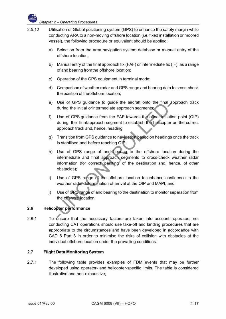
2) On passing the FAP, the helicopter will descend below the intermediate approach altitude and follow a descent gradient which should not be steeper than 6.5 %. At this stage, vertical separation from the offshore obstacle environment will be lost. However, within the final approach area, the MDA/MDH will provide separation from the surface environment.
Chapter 2 – Operating Procedures
Issue 01/Rev 00 CAGM 6008 (VII) – HOFO 2-15
3) Descent from 1 000 ft AMSL to 200 ft AMSL at a constant 6.5 % gradientwill involve a horizontal distance of 2 nm.
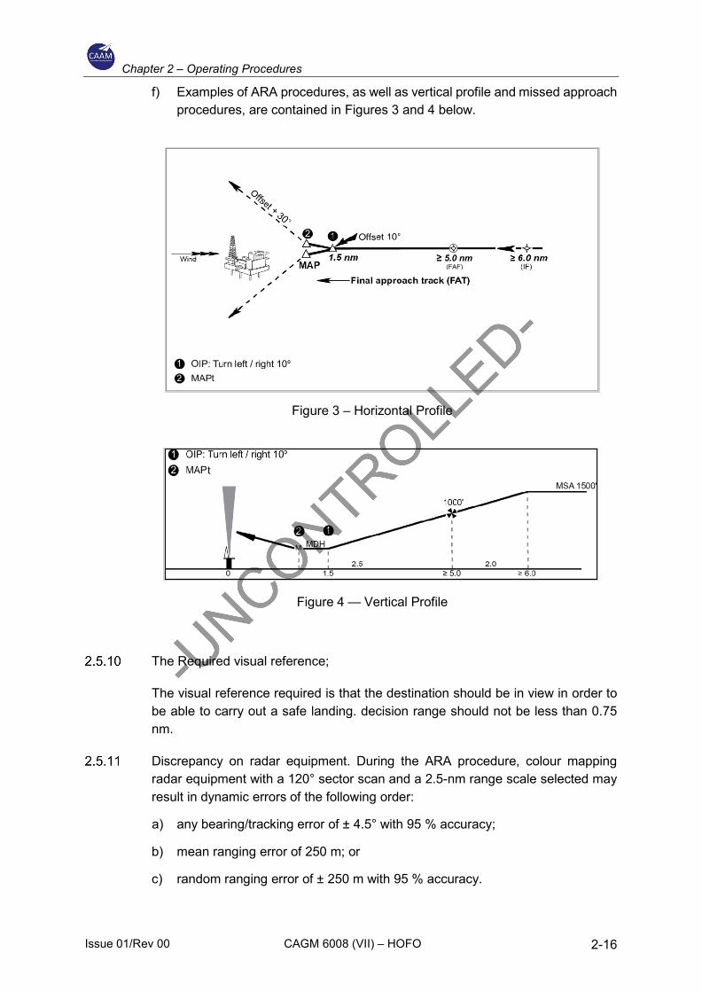
4) In order to follow the guideline that the procedure should not generatean unacceptably high workload for the flight crew, the required actions oflevelling off at MDH, changing heading at the offset initiation point (OIP),and turning away at the MAPt, should not be planned to occur at the sametime from the destination.
5) During the final approach, compensation for drift should be applied, andthe heading which, if maintained, would take the helicopter directly to thedestination should be identified.
6) It follows that at an OIP located at a range of 1.5 nm, a heading changeof 10° is likely to result in a track offset of 15° at 1 nm, and the extendedcentre line of the new track can be expected to have a mean positionapproximately 300–400 m to one side of the destination structure.
7) The safety margin built into the 0.75-nm decision range (DR) isdependent upon the rate of closure with the destination.
8) Although the airspeed should be in the range of 60–90 KIAS during thefinal approach, the ground speed, after factoring in wind velocity, shouldnot be greater than 70 kt.
e) The missed approach segment commences at the MAPt and ends whenthe helicopter reaches the minimum en route altitude.
1) The missed approach manoeuvre is a ‘turning missed approach’ whichshould be of not less than 30° and should not, normally, be greater than45°. A turn away of more than 45° does not reduce the collision risk factorany further nor does it permit a closer DR.
2) However, turns of more than 45° may increase the risk of pilotdisorientation, and by inhibiting the rate of climb (especially in the case ofan OEI missed approach procedure), may keep the helicopter at anextremely low level for longer than it is desirable.
3) The missed approach area to be used should be identified and verifiedas a clear area on the radar screen during the intermediate approachsegment. The base of the missed approach area is a sloping surface at2.5 % gradient starting from MDH at the MAPt.
4) The concept is that a helicopter executing a turning missed approach willbe protected by the horizontal boundaries of the missed approach areauntil vertical separation of more than 130 ft is achieved between the baseof the area and the offshore obstacle environment of 500 ft AMSL thatprevails outside the area.
5) A missed approach area, taking the form of a 45° sector orientated left orright of the final approach track, originating from a point 5 nm short of thedestination, and terminating on an arc 3 nm beyond the destination,should normally satisfy the specifications of a 30° turning missedapproach.
Chapter 2 – Operating Procedures
Issue 01/Rev 00 CAGM 6008 (VII) – HOFO 2-16
f) Examples of ARA procedures, as well as vertical profile and missed approachprocedures, are contained in Figures 3 and 4 below.
Figure 3 – Horizontal Profile
Figure 4 — Vertical Profile
The Required visual reference;
The visual reference required is that the destination should be in view in order to be able to carry out a safe landing. decision range should not be less than 0.75 nm.
Discrepancy on radar equipment. During the ARA procedure, colour mapping radar equipment with a 120° sector scan and a 2.5-nm range scale selected may result in dynamic errors of the following order:
a) any bearing/tracking error of ± 4.5° with 95 % accuracy;
b) mean ranging error of 250 m; or
c) random ranging error of ± 250 m with 95 % accuracy.
s ≥ 5.0 nm (FAF)
≥ 5.0
t
t
Chapter 2 – Operating Procedures
Issue 01/Rev 00 CAGM 6008 (VII) – HOFO 2-17
Utilisation of Global positioning system (GPS) to enhance the safety margin while conducting ARA to a non-moving offshore location (i.e. fixed installation or moored vessel), the following procedure or equivalent should be applied;
a) Selection from the area navigation system database or manual entry of the offshore location;
b) Manual entry of the final approach fix (FAF) or intermediate fix (IF), as a range of and bearing from the offshore location;
c) Operation of the GPS equipment in terminal mode;
d) Comparison of weather radar and GPS range and bearing data to cross-check the position of the offshore location;
e) Use of GPS guidance to guide the aircraft onto the final approach track during the initial or intermediate approach segments;
f) Use of GPS guidance from the FAF towards the offset initiation point (OIP) during the final approach segment to establish the helicopter on the correct approach track and, hence, heading;
g) Transition from GPS guidance to navigation based on headings once the track is stabilised and before reaching OIP;
h) Use of GPS range of and bearing to the offshore location during the intermediate and final approach segments to cross-check weather radar information (for correct ‘painting’ of the destination and, hence, of other obstacles);
i) Use of GPS range of the offshore location to enhance confidence in the weather radar determination of arrival at the OIP and MAPt; and
j) Use of GPS range of and bearing to the destination to monitor separation from the offshore location.
2.6 Helicopter performance
To ensure that the necessary factors are taken into account, operators not conducting CAT operations should use take-off and landing procedures that are appropriate to the circumstances and have been developed in accordance with CAD 6 Part 3 in order to minimise the risks of collision with obstacles at the individual offshore location under the prevailing conditions.
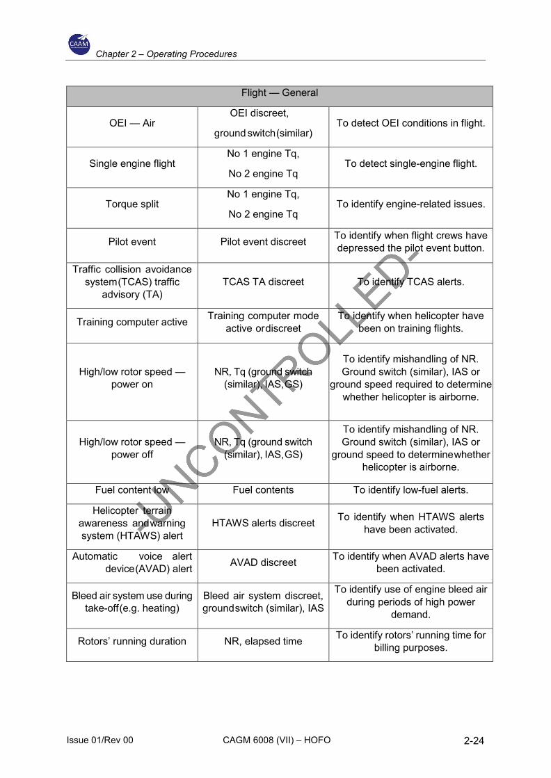
2.7 Flight Data Monitoring System
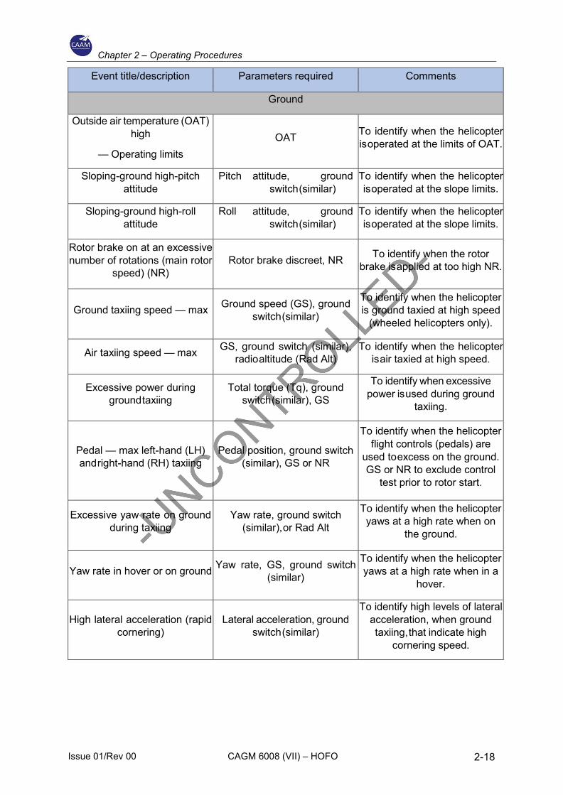
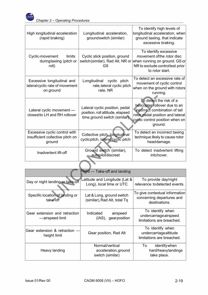
The following table provides examples of FDM events that may be further developed using operator- and helicopter-specific limits. The table is considered illustrative and non-exhaustive;
Chapter 2 – Operating Procedures
Issue 01/Rev 00 CAGM 6008 (VII) – HOFO 2-18
Event title/description Parameters required Comments
Ground
Outside air temperature (OAT) high
— Operating limits OAT To identify when the helicopter
is operated at the limits of OAT.
Sloping-ground high-pitch attitude
Pitch attitude, ground switch (similar)
To identify when the helicopter is operated at the slope limits.
Sloping-ground high-roll attitude
Roll attitude, ground switch (similar)
To identify when the helicopter is operated at the slope limits.
Rotor brake on at an excessive number of rotations (main rotor
speed) (NR) Rotor brake discreet, NR To identify when the rotor
brake is applied at too high NR.
Ground taxiing speed — max Ground speed (GS), ground switch (similar)
To identify when the helicopter is ground taxied at high speed
(wheeled helicopters only).
Air taxiing speed — max GS, ground switch (similar), radio altitude (Rad Alt)
To identify when the helicopter is air taxied at high speed.
Excessive power during ground taxiing
Total torque (Tq), ground switch (similar), GS
To identify when excessive power is used during ground
taxiing.
Pedal — max left-hand (LH) and right-hand (RH) taxiing
Pedal position, ground switch (similar), GS or NR
To identify when the helicopter flight controls (pedals) are
used to excess on the ground. GS or NR to exclude control
test prior to rotor start.
Excessive yaw rate on ground during taxiing
Yaw rate, ground switch (similar), or Rad Alt
To identify when the helicopter yaws at a high rate when on
the ground.
Yaw rate in hover or on ground Yaw rate, GS, ground switch (similar)
To identify when the helicopter yaws at a high rate when in a
hover.
High lateral acceleration (rapid cornering)
Lateral acceleration, ground switch (similar)
To identify high levels of lateral acceleration, when ground taxiing, that indicate high
cornering speed.
Chapter 2 – Operating Procedures
Issue 01/Rev 00 CAGM 6008 (VII) – HOFO 2-19
High longitudinal acceleration (rapid braking)
Longitudinal acceleration, ground switch (similar)
To identify high levels of longitudinal acceleration, when
ground taxiing, that indicate excessive braking.
Cyclic-movement limits during taxiing (pitch or
roll)
Cyclic stick position, ground switch (similar), Rad Alt, NR or
GS
To identify excessive movement of the rotor disc
when running on ground. GS or NR to exclude control test prior
to rotor start.
Excessive longitudinal and lateral cyclic rate of movement
on ground
Longitudinal cyclic pitch rate, lateral cyclic pitch
rate, NR
To detect an excessive rate of movement of cyclic control
when on the ground with rotors running.
Lateral cyclic movement — closest to LH and RH rollover
Lateral cyclic position, pedal position, roll attitude, elapsed time, ground switch (similar)
To detect the risk of a helicopter rollover due to an incorrect combination of tail
rotor pedal position and lateral cyclic control position when on
ground.
Excessive cyclic control with insufficient collective pitch on
ground
Collective pitch, longitudinal cyclic pitch, lateral cyclic pitch
To detect an incorrect taxiing technique likely to cause rotor
head damage.
Inadvertent lift-off Ground switch (similar), autopilot discreet
To detect inadvertent lifting into hover.
Flight — Take-off and landing
Day or night landing or take-off Latitude and Longitude (Lat & Long), local time or UTC
To provide day/night relevance to detected events.
Specific location of landing or take- off
Lat & Long, ground switch (similar), Rad Alt, total Tq
To give contextual information concerning departures and
destinations.
Gear extension and retraction — airspeed limit
Indicated airspeed (IAS), gear position
To identify when undercarriage airspeed
limitations are breached.
Gear extension & retraction — height limit Gear position, Rad Alt
To identify when undercarriage altitude
limitations are breached.
Heavy landing Normal/vertical
acceleration, ground switch (similar)
To identify when hard/heavy landings
take place.
Chapter 2 – Operating Procedures
Issue 01/Rev 00 CAGM 6008 (VII) – HOFO 2-20
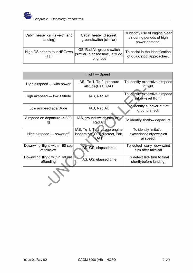
Cabin heater on (take-off and landing)
Cabin heater discreet, ground switch (similar)
To identify use of engine bleed air during periods of high
power demand.
High GS prior to toucHRGown (TD)
GS, Rad Alt, ground switch (similar), elapsed time, latitude,
longitude
To assist in the identification of ‘quick stop’ approaches.
Flight — Speed
High airspeed — with power IAS, Tq 1, Tq 2, pressure altitude (Palt), OAT
To identify excessive airspeed in flight.
High airspeed — low altitude IAS, Rad Alt To identify excessive airspeed in low-level flight.
Low airspeed at altitude IAS, Rad Alt To identify a ‘hover out of ground’ effect.
Airspeed on departure (< 300 ft)
IAS, ground switch (similar), Rad Alt To identify shallow departure.
High airspeed — power off IAS, Tq 1, Tq 2 or one engine inoperative (OEI) discreet, Palt,
OAT
To identify limitation exceedance of power-off
airspeed.
Downwind flight within 60 sec of take-off IAS, GS, elapsed time To detect early downwind
turn after take-off
Downwind flight within 60 sec of landing IAS, GS, elapsed time To detect late turn to final
shortly before landing.
Chapter 2 – Operating Procedures
Issue 01/Rev 00 CAGM 6008 (VII) – HOFO 2-21
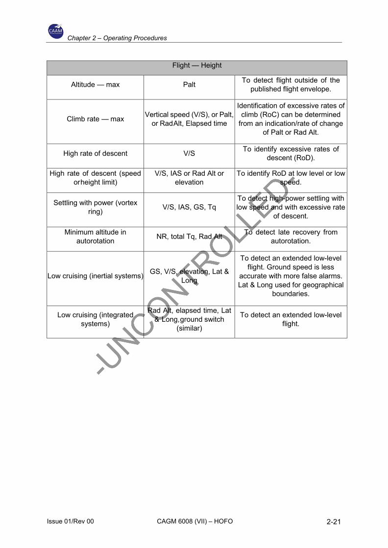
Flight — Height
Altitude — max Palt To detect flight outside of the published flight envelope.
Climb rate — max Vertical speed (V/S), or Palt, or Rad Alt, Elapsed time
Identification of excessive rates of climb (RoC) can be determined
from an indication/rate of change of Palt or Rad Alt.
High rate of descent V/S To identify excessive rates of descent (RoD).
High rate of descent (speed or height limit)
V/S, IAS or Rad Alt or elevation
To identify RoD at low level or low speed.
Settling with power (vortex ring) V/S, IAS, GS, Tq
To detect high-power settling with low speed and with excessive rate
of descent.
Minimum altitude in autorotation NR, total Tq, Rad Alt To detect late recovery from
autorotation.
Low cruising (inertial systems) GS, V/S, elevation, Lat & Long
To detect an extended low-level flight. Ground speed is less
accurate with more false alarms. Lat & Long used for geographical
boundaries.
Low cruising (integrated systems)
Rad Alt, elapsed time, Lat & Long, ground switch
(similar)
To detect an extended low-level flight.
Chapter 2 – Operating Procedures
Issue 01/Rev 00 CAGM 6008 (VII) – HOFO 2-22
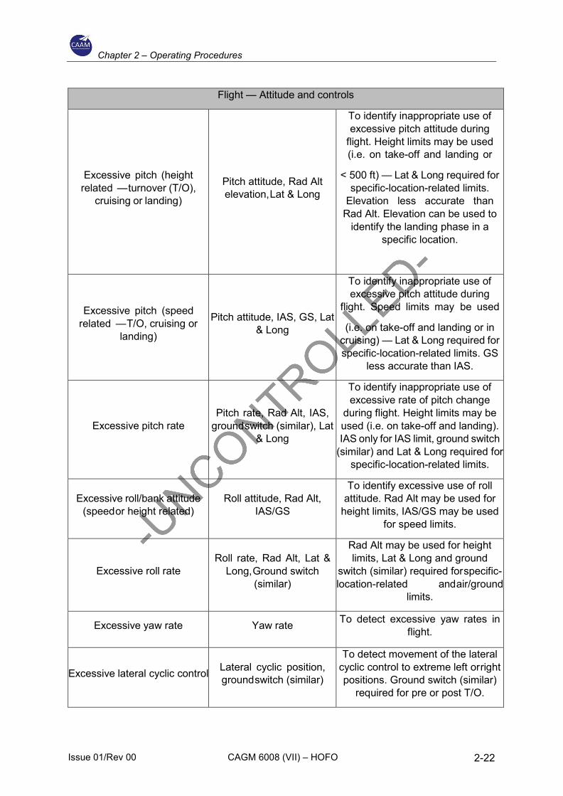
Flight — Attitude and controls
Excessive pitch (height related — turnover (T/O),
cruising or landing)
Pitch attitude, Rad Alt elevation, Lat & Long
To identify inappropriate use of excessive pitch attitude during
flight. Height limits may be used (i.e. on take-off and landing or
< 500 ft) — Lat & Long required for specific-location-related limits.
Elevation less accurate than Rad Alt. Elevation can be used to
identify the landing phase in a specific location.
Excessive pitch (speed related — T/O, cruising or
landing)
Pitch attitude, IAS, GS, Lat & Long
To identify inappropriate use of excessive pitch attitude during
flight. Speed limits may be used
(i.e. on take-off and landing or in cruising) — Lat & Long required for specific-location-related limits. GS
less accurate than IAS.
Excessive pitch rate Pitch rate, Rad Alt, IAS,
ground switch (similar), Lat & Long
To identify inappropriate use of excessive rate of pitch change
during flight. Height limits may be used (i.e. on take-off and landing). IAS only for IAS limit, ground switch
(similar) and Lat & Long required for specific-location-related limits.
Excessive roll/bank attitude (speed or height related)
Roll attitude, Rad Alt, IAS/GS
To identify excessive use of roll attitude. Rad Alt may be used for
height limits, IAS/GS may be used for speed limits.
Excessive roll rate Roll rate, Rad Alt, Lat &
Long, Ground switch (similar)
Rad Alt may be used for height limits, Lat & Long and ground
switch (similar) required for specific-location-related and air/ground
limits.
Excessive yaw rate Yaw rate To detect excessive yaw rates in flight.
Excessive lateral cyclic control Lateral cyclic position, ground switch (similar)
To detect movement of the lateral cyclic control to extreme left or right positions. Ground switch (similar)
required for pre or post T/O.
Chapter 2 – Operating Procedures
Issue 01/Rev 00 CAGM 6008 (VII) – HOFO 2-23
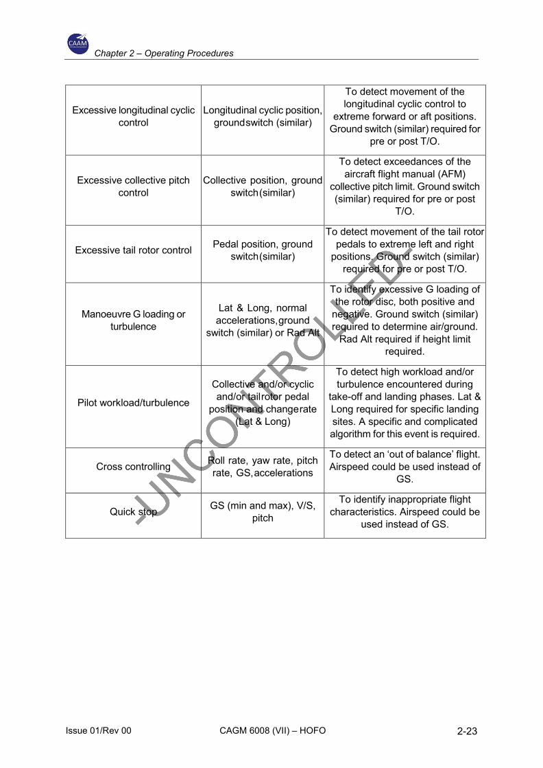
Excessive longitudinal cyclic control
Longitudinal cyclic position, ground switch (similar)
To detect movement of the longitudinal cyclic control to
extreme forward or aft positions. Ground switch (similar) required for
pre or post T/O.
Excessive collective pitch control
Collective position, ground switch (similar)
To detect exceedances of the aircraft flight manual (AFM)
collective pitch limit. Ground switch (similar) required for pre or post
T/O.
Excessive tail rotor control Pedal position, ground switch (similar)
To detect movement of the tail rotor pedals to extreme left and right
positions. Ground switch (similar) required for pre or post T/O.
Manoeuvre G loading or turbulence
Lat & Long, normal accelerations, ground
switch (similar) or Rad Alt
To identify excessive G loading of the rotor disc, both positive and
negative. Ground switch (similar) required to determine air/ground.
Rad Alt required if height limit required.
Pilot workload/turbulence
Collective and/or cyclic and/or tail rotor pedal
position and change rate (Lat & Long)
To detect high workload and/or turbulence encountered during
take-off and landing phases. Lat & Long required for specific landing sites. A specific and complicated algorithm for this event is required.
Cross controlling Roll rate, yaw rate, pitch rate, GS, accelerations
To detect an ‘out of balance’ flight. Airspeed could be used instead of
GS.
Quick stop GS (min and max), V/S, pitch
To identify inappropriate flight characteristics. Airspeed could be
used instead of GS.
Chapter 2 – Operating Procedures
Issue 01/Rev 00 CAGM 6008 (VII) – HOFO 2-24
Flight — General
OEI — Air OEI discreet,
ground switch (similar) To detect OEI conditions in flight.
Single engine flight No 1 engine Tq,
No 2 engine Tq To detect single-engine flight.
Torque split No 1 engine Tq,
No 2 engine Tq To identify engine-related issues.
Pilot event Pilot event discreet To identify when flight crews have depressed the pilot event button.
Traffic collision avoidance system (TCAS) traffic
advisory (TA) TCAS TA discreet To identify TCAS alerts.
Training computer active Training computer mode active or discreet
To identify when helicopter have been on training flights.
High/low rotor speed — power on
NR, Tq (ground switch (similar), IAS, GS)
To identify mishandling of NR. Ground switch (similar), IAS or
ground speed required to determine whether helicopter is airborne.
High/low rotor speed — power off
NR, Tq (ground switch (similar), IAS, GS)
To identify mishandling of NR. Ground switch (similar), IAS or
ground speed to determine whether helicopter is airborne.
Fuel content low Fuel contents To identify low-fuel alerts.
Helicopter terrain awareness and warning system (HTAWS) alert
HTAWS alerts discreet To identify when HTAWS alerts have been activated.
Automatic voice alert device (AVAD) alert AVAD discreet To identify when AVAD alerts have
been activated.
Bleed air system use during take-off (e.g. heating)
Bleed air system discreet, ground switch (similar), IAS
To identify use of engine bleed air during periods of high power
demand.
Rotors’ running duration NR, elapsed time To identify rotors’ running time for billing purposes.
Chapter 2 – Operating Procedures
Issue 01/Rev 00 CAGM 6008 (VII) – HOFO 2-25
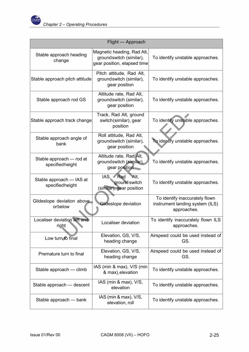
Flight — Approach
Stable approach heading change
Magnetic heading, Rad Alt, ground switch (similar),
gear position, elapsed time To identify unstable approaches.
Stable approach pitch attitude Pitch attitude, Rad Alt, ground switch (similar),
gear position To identify unstable approaches.
Stable approach rod GS Altitude rate, Rad Alt, ground switch (similar),
gear position To identify unstable approaches.
Stable approach track change Track, Rad Alt, ground
switch (similar), gear position
To identify unstable approaches.
Stable approach angle of bank
Roll attitude, Rad Alt, ground switch (similar),
gear position To identify unstable approaches.
Stable approach — rod at specified height
Altitude rate, Rad Alt, ground switch (similar),
gear position To identify unstable approaches.
Stable approach — IAS at specified height
IAS, Rad Alt, ground switch (similar), gear position
To identify unstable approaches.
Glideslope deviation above or below Glideslope deviation
To identify inaccurately flown instrument landing system (ILS)
approaches.
Localiser deviation left and right Localiser deviation To identify inaccurately flown ILS
approaches.
Low turn to final Elevation, GS, V/S, heading change
Airspeed could be used instead of GS.
Premature turn to final Elevation, GS, V/S, heading change
Airspeed could be used instead of GS.
Stable approach — climb IAS (min & max), V/S (min & max), elevation To identify unstable approaches.
Stable approach — descent IAS (min & max), V/S, elevation To identify unstable approaches.
Stable approach — bank IAS (min & max), V/S, elevation, roll To identify unstable approaches.
Chapter 2 – Operating Procedures
Issue 01/Rev 00 CAGM 6008 (VII) – HOFO 2-26
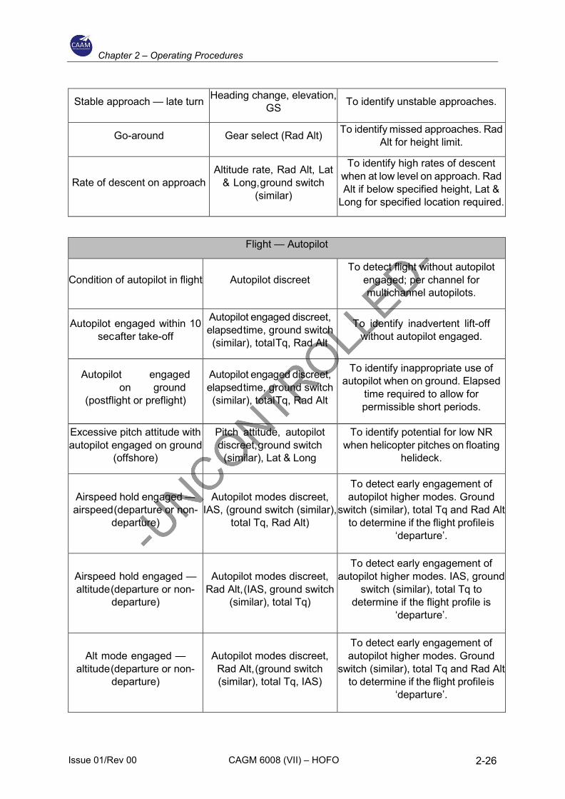
Stable approach — late turn Heading change, elevation, GS To identify unstable approaches.
Go-around Gear select (Rad Alt) To identify missed approaches. Rad Alt for height limit.
Rate of descent on approach Altitude rate, Rad Alt, Lat
& Long, ground switch (similar)
To identify high rates of descent when at low level on approach. Rad Alt if below specified height, Lat &
Long for specified location required.
Flight — Autopilot
Condition of autopilot in flight Autopilot discreet To detect flight without autopilot
engaged; per channel for multichannel autopilots.
Autopilot engaged within 10 sec after take-off
Autopilot engaged discreet, elapsed time, ground switch (similar), total Tq, Rad Alt
To identify inadvertent lift-off without autopilot engaged.
Autopilot engaged on ground (postflight or preflight)
Autopilot engaged discreet, elapsed time, ground switch (similar), total Tq, Rad Alt
To identify inappropriate use of autopilot when on ground. Elapsed
time required to allow for permissible short periods.
Excessive pitch attitude with autopilot engaged on ground
(offshore)
Pitch attitude, autopilot discreet, ground switch (similar), Lat & Long
To identify potential for low NR when helicopter pitches on floating
helideck.
Airspeed hold engaged — airspeed (departure or non-
departure)
Autopilot modes discreet, IAS, (ground switch (similar),
total Tq, Rad Alt)
To detect early engagement of autopilot higher modes. Ground
switch (similar), total Tq and Rad Alt to determine if the flight profile is
‘departure’.
Airspeed hold engaged — altitude (departure or non-
departure)
Autopilot modes discreet, Rad Alt, (IAS, ground switch
(similar), total Tq)
To detect early engagement of autopilot higher modes. IAS, ground
switch (similar), total Tq to determine if the flight profile is
‘departure’.
Alt mode engaged — altitude (departure or non-
departure)
Autopilot modes discreet, Rad Alt, (ground switch (similar), total Tq, IAS)
To detect early engagement of autopilot higher modes. Ground
switch (similar), total Tq and Rad Alt to determine if the flight profile is
‘departure’.
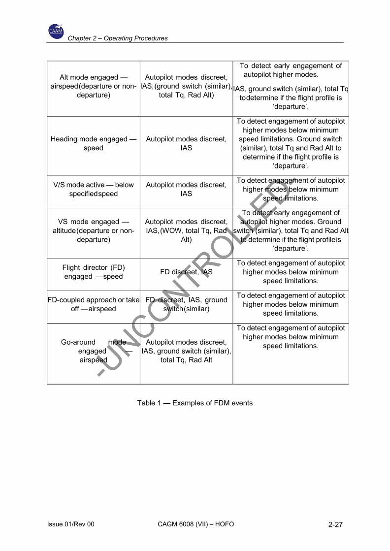
Chapter 2 – Operating Procedures
Issue 01/Rev 00 CAGM 6008 (VII) – HOFO 2-27
Alt mode engaged — airspeed (departure or non-
departure)
Autopilot modes discreet, IAS, (ground switch (similar),
total Tq, Rad Alt)
To detect early engagement of autopilot higher modes.
IAS, ground switch (similar), total Tq to determine if the flight profile is
‘departure’.
Heading mode engaged — speed
Autopilot modes discreet, IAS
To detect engagement of autopilot higher modes below minimum
speed limitations. Ground switch (similar), total Tq and Rad Alt to determine if the flight profile is
‘departure’.
V/S mode active — below specified speed
Autopilot modes discreet, IAS
To detect engagement of autopilot higher modes below minimum
speed limitations.
VS mode engaged — altitude (departure or non-
departure)
Autopilot modes discreet, IAS, (WOW, total Tq, Rad
Alt)
To detect early engagement of autopilot higher modes. Ground
switch (similar), total Tq and Rad Alt to determine if the flight profile is
‘departure’.
Flight director (FD) engaged — speed FD discreet, IAS
To detect engagement of autopilot higher modes below minimum
speed limitations.
FD-coupled approach or take off — airspeed
FD discreet, IAS, ground switch (similar)
To detect engagement of autopilot higher modes below minimum
speed limitations.
Go-around mode engaged —
airspeed
Autopilot modes discreet, IAS, ground switch (similar),
total Tq, Rad Alt
To detect engagement of autopilot higher modes below minimum
speed limitations.
Table 1 — Examples of FDM events
Chapter 2 – Operating Procedures
Issue 01/Rev 00 CAGM 6008 (VII) – HOFO 2-28
2.8 Aircraft tracking system
The Flights should be tracked and monitored from take-off to landing. This function may be achieved by the air traffic services (ATS) when the planned route and the planned diversion routes are fully included in airspace blocks where:
a) Selection ATS surveillance service is normally provided and supported by ATC surveillance systems locating the aircraft at time intervals with adequate duration; and
b) The operator has given to competent air navigation services (ANS) providers the necessary contact information.
In all other cases, the operator should establish a detailed procedure describing how the aircraft tracking system is to be monitored, and what actions and when are to be taken if a deviation or anomaly has been detected.
a) The outcome of the risk assessment made when the update frequency of the information was defined;
b) The local environment of the intended operations; and
c) The relationship with the operator’s emergency response plan.
Operator also need to have a standard procedure in managing all the data in this system.
Aircraft tracking data should be recorded on the ground and retained for at least 48 h. Following an accident or a serious incident subject to investigation, the data should be retained for at least 30 days, and the operator should be capable of providing a copy of this data without delay.
2.9 Vibration Health Monitoring (VHM) System
The Operators should utilise available international guidance material provided for the specification and design of VHM systems. Any VHM system should meet all of the following criteria:
a) The VHM system should be capable of measure vibration characteristics of rotating critical components during flight, using suitable vibration sensors, techniques, and recording equipment. The frequency and flight phases of data measurement should be established together with the type certificate holder (TCH) during the initial entry into service.
b) In order to appropriately manage the generated data and focus upon significant issues, an alerting system should be established; this is normally automatic. Accordingly, alert generation processes should be developed to reliably advise maintenance personnel of the need to intervene and help determine what type of intervention is required.
Chapter 2 – Operating Procedures
Issue 01/Rev 00 CAGM 6008 (VII) – HOFO 2-29
c) The VHM installation must be approved which typically comprises vibration sensors and associated wiring, data acquisition and processing hardware, the means of downloading data from the helicopter, the ground-based system and all associated instructions for operation of the system, should be certified by CAAM.
The Operators must establish procedures to address all necessary VHM subjects including the training for the VHM operating staff. This also to include determine the appropriate syllabi, and incorporate them into the operator’s initial and recurrent training programmes.
2.10 Additional equipment requirement
The Public Address (PA) System. When demonstrating the performance of the PA system or that the pilot’s voice is understandable at all passengers’ seats during flight, the operator should ensure compatibility with the passengers’ use of ear defenders/ear plugs (hearing protection). The operator should only provide hearing protection that is compatible with the intelligibility of the PA system or pilot’s voice, as appropriate.
Radio Altimeter. Helicopters shall be equipped with a radio altimeter that is capable of emitting an audio warning below a pre-set height and a visual warning at a height selectable by the pilot.
Emergency Breathing System that capable of rapid underwater deployment is appropriate for use by passengers or crew, and has been demonstrated not to interfere with the correct operation of the approved survival suits or life jackets or crew duties.
Life Raft. The installation must be;
a) The projections on the exterior surface of the helicopter that are located in a zone delineated by boundaries that are 1.22 m (4 ft) above and 0.61 m (2 ft) below the established static waterline could cause damage to a deployed life raft. Examples of projections that need to be considered are aerials, overboard vents, unprotected split-pin tails, guttering, and any projection sharper than a three-dimensional right-angled corner.
b) While the boundaries specified in a) above are intended as a guide, the total area that should be considered should also take into account the likely behaviour of the life raft after deployment in all sea states up to the maximum in which the helicopter is capable of remaining upright.
c) Wherever a modification or alteration is made to a helicopter within the boundaries specified, the need to prevent the modification or alteration from causing damage to a deployed life raft should be taken into account in the design.
Chapter 2 – Operating Procedures
Issue 01/Rev 00 CAGM 6008 (VII) – HOFO 2-30
d) Particular care should also be taken during routine maintenance to ensure that additional hazards are not introduced by, for example, leaving inspection panels with sharp corners proud of the surrounding fuselage surface, or by allowing door sills to deteriorate to a point where their sharp edges may become a hazard.
The criteria for the Emergency Exits and Escape Hatches and in order for all passengers to escape from the helicopter within an expected underwater survival time of 60 sec in the event of capsize, the following provisions should be made:
a) There should be an easily accessible emergency exit or suitable opening for each passenger;
b) An opening in the passenger compartment should be considered suitable as an underwater escape facility if the following criteria are met:
1) The means of opening should be rapid and obvious; 2) Passenger safety briefing material should include instructions on the use
of such escape facilities; 3) For the egress of passengers with shoulder width of 559 mm (22 in.) Or
smaller, a rectangular opening should be no smaller than 356 mm (14 in.) Wide, with a diagonal between corner radii no smaller than 559 mm (22 in.), when operated in accordance with the instructions;
4) Non-rectangular or partially obstructed openings (e.g. By a seat back) should be capable of admitting an ellipse of 559 mm x 356 mm (22 in. X 14 in.); and
5) For the egress of passengers with shoulder width greater than 559 mm (22 in.), openings should be no smaller than 480 mm x 660 mm (19 in. X 26 in.) Or be capable of admitting an ellipse of 480 mm x 660 mm (19 in. X 26 in.);
c) Suitable openings and emergency exits should be used for the underwater escape of no more than two passengers, unless large enough to permit the simultaneous egress of two passengers side by side:
1) If the exit size provides an unobstructed area that encompasses two ellipses of size 480 mm x 660 m (19 in. x 26 in.) side by side, then it may be used for four passengers;
2) If the exit size provides an unobstructed area that encompasses two ellipses of size 356 mm x 559 mm (14 in. x 22 in.) side by side, then it may be used for four passengers with shoulder width no greater than 559 mm (22 in.) each; and
d) Passengers with shoulder width greater than 559 mm (22 in.) should be identified and allocated to seats with easy access to an emergency exit or opening that is suitable for them.
Chapter 2 – Operating Procedures
Issue 01/Rev 00 CAGM 6008 (VII) – HOFO 2-31
2.11 Additional procedures requirement
Passenger Seat Allocation. The identification and seating of the larger passengers might be achieved through the use of patterned and/or colour-coded armbands and matching seat headrests.
A ‘Medically Incapacitated Passenger’ means a person who is unable to wear the required survival equipment, including life jackets, survival suits and emergency breathing systems (EBSs), as determined by a medical professional.
The medical professional’s determination should be made available to the pilot-in-command/commander prior to arrival at the offshore installation.
The operator should establish procedures for the cases where the pilot-in-command/commander may accept a medically incapacitated passenger not wearing or partially wearing survival equipment.
To ensure proportionate mitigation of the risks associated with an evacuation, the procedures should be based on, but not be limited to, the severity of the incapacitation, sea and air temperature, sea state, and number of passengers on board.
In addition, the operator should establish the following procedures:
a) The under which circumstances one or more dedicated persons are required to assist a medically incapacitated passenger during a possible emergency evacuation, and the skills and qualifications required;
b) Seat allocation for the medically incapacitated passenger and possible assistants in the helicopter types used to ensure optimum use of the emergency exits; and
c) Evacuation procedures related to whether or not the dedicated persons as described in a) above are present.
2.12 Flight crew training and checking
Flight crew training programmes should:
a) Improve knowledge of the offshore operations environment with particular consideration of visual illusions during approach, introduced by lighting, motion and weather factors;
b) Improve crew cooperation specifically for offshore operations;
c) Provide flight crew members with the necessary skills to appropriately manage the risks associated with normal, abnormal and emergency procedures during flights by day and night;
d) If night operations are conducted, give particular consideration to approach, go-around, landing, and take-off phases;
Chapter 2 – Operating Procedures
Issue 01/Rev 00 CAGM 6008 (VII) – HOFO 2-32
e) Include instructions on the optimum use of the helicopter’s automatic flight control system (AFCS);
f) For multi-pilot operation, emphasise the importance of multi-crew procedures, as well as the role of the pilot monitoring during all phases of the flight; and
g) Include standard operating procedures.
Emergency and safety equipment training should focus on the equipment fitted/carried. Water entry and sea survival training, including operation of all associated safety equipment, should be an element of the recurrent training, as described in CAD 6 Part 3.
The training elements referred to above should be assessed during operator proficiency checks, line checks or as applicable, emergency and safety equipment checks.
The training and checking should make full use of full flight simulators (FFSs) for normal, abnormal and emergency procedures related to all aspects of helicopter offshore operations (HOFO).
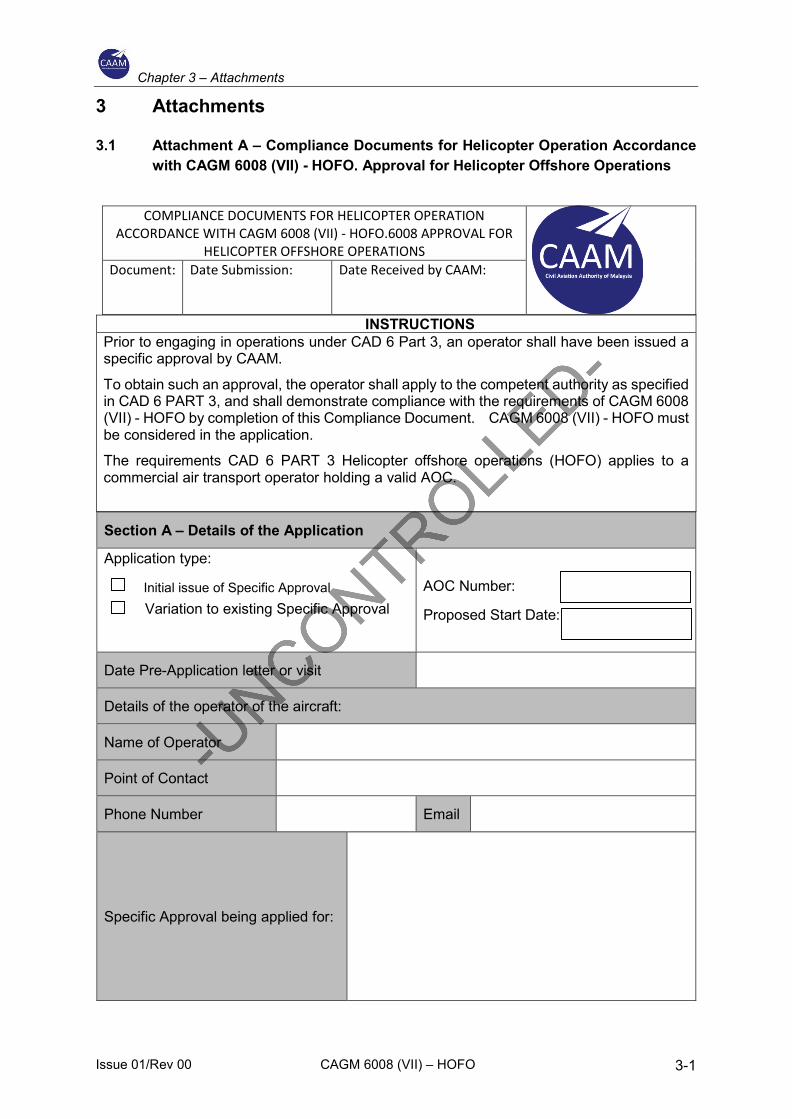
Chapter 3 – Attachments
Issue 01/Rev 00 CAGM 6008 (VII) – HOFO 3-1
3 Attachments
3.1 Attachment A – Compliance Documents for Helicopter Operation Accordance with CAGM 6008 (VII) - HOFO. Approval for Helicopter Offshore Operations
COMPLIANCE DOCUMENTS FOR HELICOPTER OPERATION ACCORDANCE WITH CAGM 6008 (VII) - HOFO.6008 APPROVAL FOR
HELICOPTER OFFSHORE OPERATIONS
Document: Date Submission: Date Received by CAAM:
INSTRUCTIONS Prior to engaging in operations under CAD 6 Part 3, an operator shall have been issued a specific approval by CAAM.
To obtain such an approval, the operator shall apply to the competent authority as specified in CAD 6 PART 3, and shall demonstrate compliance with the requirements of CAGM 6008 (VII) - HOFO by completion of this Compliance Document. CAGM 6008 (VII) - HOFO must be considered in the application.
The requirements CAD 6 PART 3 Helicopter offshore operations (HOFO) applies to a commercial air transport operator holding a valid AOC.
Section A – Details of the Application
Application type: Variation to existing Specific Approval
AOC Number:
Proposed Start Date:
Date Pre-Application letter or visit
Details of the operator of the aircraft:
Name of Operator
Point of Contact
Phone Number Email
Specific Approval being applied for:
Initial issue of Specific Approval
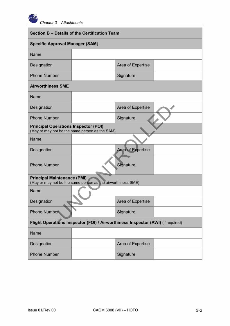
Chapter 3 – Attachments
Issue 01/Rev 00 CAGM 6008 (VII) – HOFO 3-2
Section B – Details of the Certification Team
Specific Approval Manager (SAM)
Name
Designation Area of Expertise
Phone Number Signature
Airworthiness SME
Name
Designation Area of Expertise
Phone Number Signature
Principal Operations Inspector (POI) (May or may not be the same person as the SAM)
Name
Designation Area of Expertise
Phone Number Signature
Principal Maintenance (PMI) (May or may not be the same person as the airworthiness SME)
Name
Designation Area of Expertise
Phone Number Signature
Flight Operations Inspector (FOI) / Airworthiness Inspector (AWI) (if required)
Name
Designation Area of Expertise
Phone Number Signature
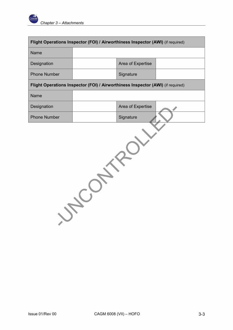
Chapter 3 – Attachments
Issue 01/Rev 00 CAGM 6008 (VII) – HOFO 3-3
Flight Operations Inspector (FOI) / Airworthiness Inspector (AWI) (if required)
Name
Designation Area of Expertise
Phone Number Signature
Flight Operations Inspector (FOI) / Airworthiness Inspector (AWI) (if required)
Name
Designation Area of Expertise
Phone Number Signature
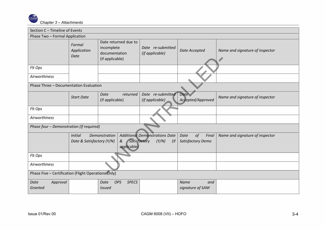
Chapter 3 – Attachments
Issue 01/Rev 00 CAGM 6008 (VII) – HOFO 3-4
Section C – Timeline of Events Phase Two – Formal Application
Formal Application Date
Date returned due to incomplete documentation (if applicable)
Date re-submitted (if applicable)
Date Accepted Name and signature of inspector
Flt Ops
Airworthiness
Phase Three – Documentation Evaluation
Start Date
Date returned (if applicable)
Date re-submitted (if applicable)
Date Accepted/Approved
Name and signature of inspector
Flt Ops
Airworthiness
Phase four – Demonstration (if required)
Initial Demonstration Date & Satisfactory (Y/N)
Additional Demonstrations Date & Satisfactory (Y/N) (if applicable)
Date of Final Satisfactory Demo
Name and signature of inspector
Flt Ops
Airworthiness
Phase Five – Certification (Flight Operations Only)
Date Approval Granted
Date OPS SPECS Issued
Name and signature of SAM

Chapter 3 – Attachments
Issue 01/Rev 00 CAGM 6008 (VII) – HOFO 3-5
Section D – Flight Operations Diary of Events
Chapter 3 – Attachments
Issue 01/Rev 00 CAGM 6008 (VII) – HOFO 3-6
Section E – Airworthiness Diary of Events
Note1. – This section is to be given to the Airworthiness SME for completion
Note2. – This section needs to filled up by the Airworthiness SME and he is responsible to ensure its completes.
Chapter 3 – Attachments
Issue 01/Rev 00 CAGM 6008 (VII) – HOFO 3-7
Section F – CAAM Director of Flight Operations
Application approved Application Rejected
Remarks
Name of DFO
Signature Date
Chapter 3 – Attachments
Issue 01/Rev 00 CAGM 6008 (VII) – HOFO 3-8
INTENTIONALLY LEFT BLANK
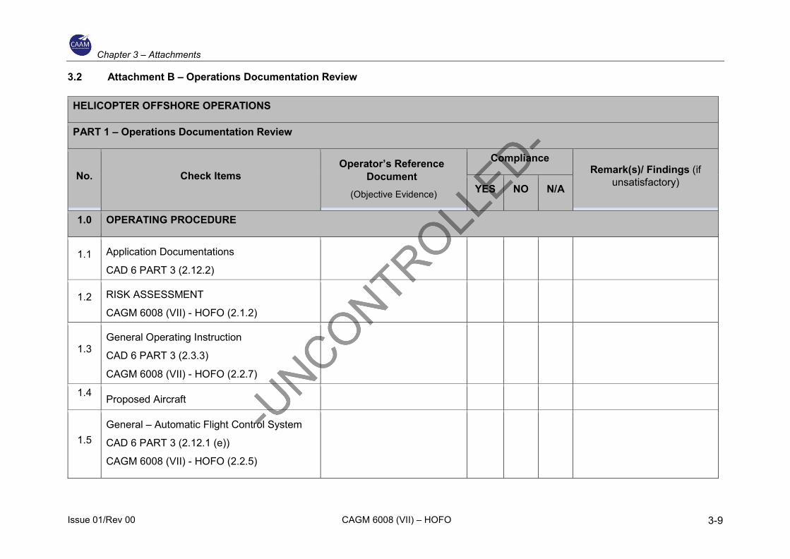
Chapter 3 – Attachments
Issue 01/Rev 00 CAGM 6008 (VII) – HOFO 3-9
3.2 Attachment B – Operations Documentation Review
HELICOPTER OFFSHORE OPERATIONS
PART 1 – Operations Documentation Review
No. Check Items Operator’s Reference
Document (Objective Evidence)
Compliance Remark(s)/ Findings (if
unsatisfactory) YES NO N/A
1.0 OPERATING PROCEDURE
1.1 Application Documentations
CAD 6 PART 3 (2.12.2)
1.2 RISK ASSESSMENT
CAGM 6008 (VII) - HOFO (2.1.2)
1.3 General Operating Instruction
CAD 6 PART 3 (2.3.3)
CAGM 6008 (VII) - HOFO (2.2.7)
1.4 Proposed Aircraft
1.5 General – Automatic Flight Control System
CAD 6 PART 3 (2.12.1 (e))
CAGM 6008 (VII) - HOFO (2.2.5)
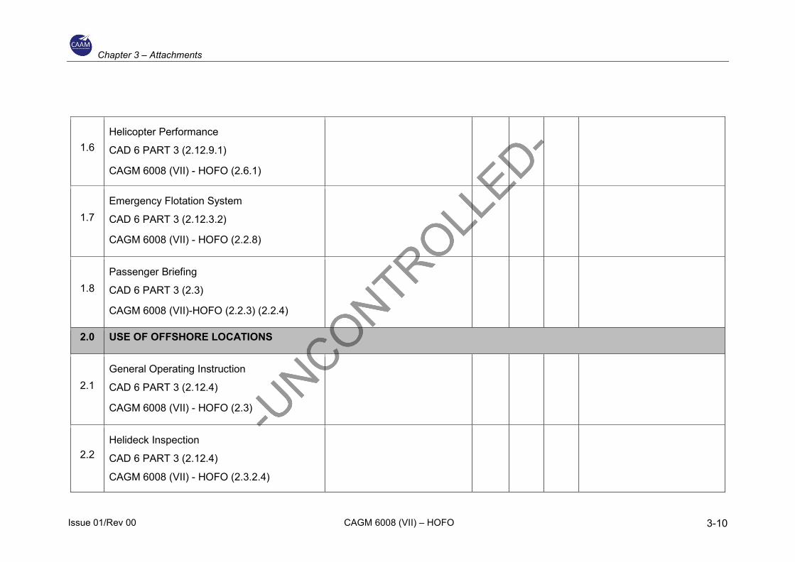
Chapter 3 – Attachments
Issue 01/Rev 00 CAGM 6008 (VII) – HOFO 3-10
1.6 Helicopter Performance
CAD 6 PART 3 (2.12.9.1)
CAGM 6008 (VII) - HOFO (2.6.1)
1.7 Emergency Flotation System
CAD 6 PART 3 (2.12.3.2)
CAGM 6008 (VII) - HOFO (2.2.8)
1.8 Passenger Briefing
CAD 6 PART 3 (2.3)
CAGM 6008 (VII)-HOFO (2.2.3) (2.2.4)
2.0 USE OF OFFSHORE LOCATIONS
2.1 General Operating Instruction
CAD 6 PART 3 (2.12.4)
CAGM 6008 (VII) - HOFO (2.3)
2.2 Helideck Inspection
CAD 6 PART 3 (2.12.4)
CAGM 6008 (VII) - HOFO (2.3.2.4)
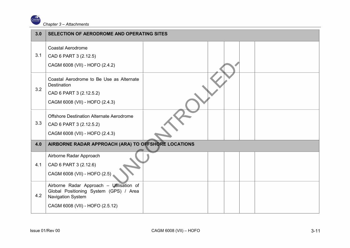
Chapter 3 – Attachments
Issue 01/Rev 00 CAGM 6008 (VII) – HOFO 3-11
3.0 SELECTION OF AERODROME AND OPERATING SITES
3.1 Coastal Aerodrome
CAD 6 PART 3 (2.12.5)
CAGM 6008 (VII) - HOFO (2.4.2)
3.2
Coastal Aerodrome to Be Use as Alternate Destination
CAD 6 PART 3 (2.12.5.2)
CAGM 6008 (VII) - HOFO (2.4.3)
3.3 Offshore Destination Alternate Aerodrome
CAD 6 PART 3 (2.12.5.2)
CAGM 6008 (VII) - HOFO (2.4.3)
4.0 AIRBORNE RADAR APPROACH (ARA) TO OFFSHORE LOCATIONS
4.1
Airborne Radar Approach
CAD 6 PART 3 (2.12.6)
CAGM 6008 (VII) - HOFO (2.5)
4.2
Airborne Radar Approach – Utilisation of Global Positioning System (GPS) / Area Navigation System
CAGM 6008 (VII) - HOFO (2.5.12)
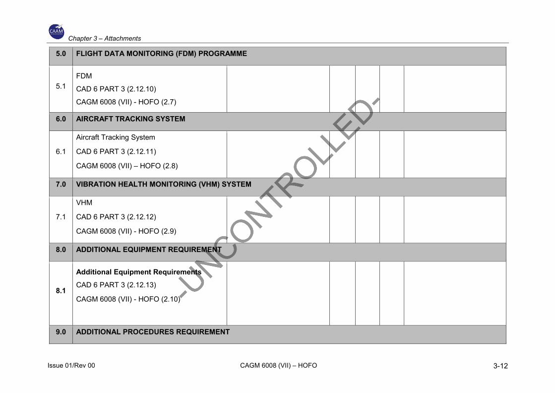
Chapter 3 – Attachments
Issue 01/Rev 00 CAGM 6008 (VII) – HOFO 3-12
5.0 FLIGHT DATA MONITORING (FDM) PROGRAMME
5.1 FDM
CAD 6 PART 3 (2.12.10)
CAGM 6008 (VII) - HOFO (2.7)
6.0 AIRCRAFT TRACKING SYSTEM
6.1
Aircraft Tracking System
CAD 6 PART 3 (2.12.11)
CAGM 6008 (VII) – HOFO (2.8)
7.0 VIBRATION HEALTH MONITORING (VHM) SYSTEM
7.1
VHM
CAD 6 PART 3 (2.12.12)
CAGM 6008 (VII) - HOFO (2.9)
8.0 ADDITIONAL EQUIPMENT REQUIREMENT
8.1
Additional Equipment Requirements CAD 6 PART 3 (2.12.13)
CAGM 6008 (VII) - HOFO (2.10)
9.0 ADDITIONAL PROCEDURES REQUIREMENT
Chapter 3 – Attachments
Issue 01/Rev 00 CAGM 6008 (VII) – HOFO 3-13
9.1 Additional Procedures CAD 6 PART 3 (2.12.14)
CAGM 6008 (VII) - HOFO (2.11)
10.0 FLIGHT CREW TRAINING AND CHECKING
10.1 Crew Requirements CAD 6 PART 3 (2.12.15)
CAGM 6008 (VII) - HOFO (2.12)

Chapter 3 – Attachments
Issue 01/Rev 00 CAGM 6008 (VII) – HOFO 3-14
INTENTIONALLY LEFT BLANK
Related Documents


