WE MOVE INDUSTRIES HEKO CONVEYOR SOLUTIONS CONVEYOR SOLUTIONS March 2019

Welcome message from author
This document is posted to help you gain knowledge. Please leave a comment to let me know what you think about it! Share it to your friends and learn new things together.
Transcript
WE MOVE INDUSTRIES HEKO CONVEYOR SOLUTIONS
CONVEYOR SOLUTIONS
March 2019

Axians Industrial Applications & Services – your IT partner for:
dispatch automation process security smart industry
We know theway forward.
Axians Industrial Applications & Services GmbHHoervelsinger Weg 17 · 89081 Ulm · [email protected] · www.axians-ias.com

ON THE COVER
CONTENTSCONTENTS03 Comment05 News80 5 Minutes... with Bernard MathieuClimate Programme Director, WCA.
Regional Report: Sub-Saharan Africa10 Roaring Lion Or Laughing HyenaYasmine Ghozzi, GlobalData, examines the construction output of Sub-Saharan Africa.
18 A Land Of OpportunityDom Pavlopoulos and Claudia Stefanoiu, Cement Business Research, provide a market analysis of the cement industries in East Africa.
Production Effi ciency & Optimisation23 The Bigger PictureMark Mutter and Lawrie Evans, JAMCEM Consulting, discuss how to optimise the cement, as well as the mill.
Cement Analysis 27 Enhanced Geopolymer Cement: AnalysisP. Ponnusamy, Mukesh K. Mishra, Praseeja Shankaran, Soumen Saha, and S.P. Pandey, Dalmia Cement Research Centre, explain how to enhance the functional features of geopolymer cement.
35 Feeling The HeatMatteo Magistri, Mapei SpA, overviews calorimetry and its applications to cements and concrete.
Air Pollution Control42 Opportunity NO
X
Helmut Hoppe, VDZ, gives an overview of the development of NO
X reduction technologies.
50 Optimising Dry Sorbent InjectionDr Ian Saratovsky, Gerald Hunt, and Martin Dillon, Lhoist, discuss sorbent application methods and system optimisation with regard to acid gas and mercury compliance costs.
Conveying57 Breaking New GroupWorld Cement examines the development of a new innovation in belt construction that has been introduced into the market.
61 Conveyor SurveyorsDaniel Marshall, Martin Engineering, discusses conveyor safety audits.
65 Between Two TowersDoppelmayr talks to World Cement about the transportation of limestone across treetops in Guatemala.
Cement Storage 67 Solid SilosMario Scutti, SCUTTI, discusses the advantages and disadvantages of various silos for bulk solids.
Refractories71 Brick By BrickLars Lindgren, Bricking Solutions, investigates how companies can take back lost profi ts with a bricking machine.
Chains77 Chained MelodyWorld Cement rounds up the latest news and views from the chains sector.
HEKO Ketten GmbH, Germany, is the head of a group of manufacturing
companies supplying products and solutions to the bulk materials handling
industry. Bucket elevators, chain conveyors, and all wear parts, including central
chains, elevator chains, and belts, are delivered to more than 90 countries.
HEKO maintains a sales and service network in all major markets.
For more information visit: www.heko.com
WE MOVE INDUSTRIES HEKO CONVEYOR SOLUTIONS
CONVEYOR SOLUTIONS
March 2019
HEKO Ketten GmbHEisenbahnstraße 2 | 58739 Wickede (Ruhr), Germany | Telephone +49(0)2377-9180-0 | Fax +49(0)2377-1028 | E-Mail: [email protected]
www.heko.com
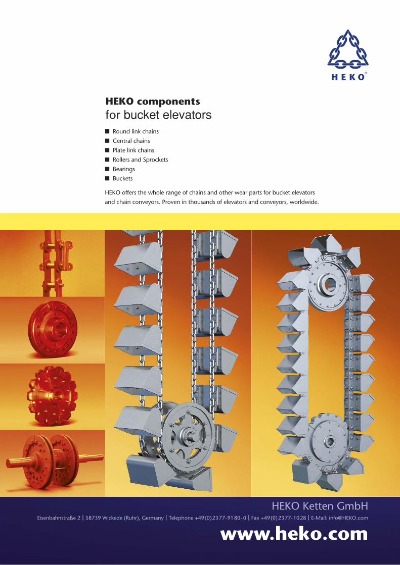
HEKO componentsfor bucket elevators� Round link chains
� Central chains
� Plate link chains
� Rollers and Sprockets
� Bearings
� Buckets
HEKO offers the whole range of chains and other wear parts for bucket elevators
and chain conveyors. Proven in thousands of elevators and conveyors, worldwide.
SUBSCRIPTIONS
COMMENTManaging Editor: James Little [email protected]
Editor: Jonathan [email protected]
Contributing Editor: Paul Maxwell-Cook
Production: Hayley [email protected]
Advertisement Director: Rod [email protected]
Advertisement Manager: Ian [email protected]
Advertisement Executive: Paul [email protected]
Website Manager: Tom [email protected]
Subscriptions: Laura [email protected]
Digital Editorial Assistant: Nick [email protected]
Editorial Assistant: Lucy [email protected]
JONATHAN ROWLAND, EDITOR
3 March 2019 World Cement
Annual subscription (published monthly): £160 UK including postage/£175 (e245) overseas (postage airmail)/US$280 USA/Canada (postage airmail). Two year subscription (published monthly): £256 UK including postage/£280 (e392) overseas (postage airmail)/US$448 USA/Canada (postage airmail). Claims for non receipt of issues must be made within 4 months of publication of the issue or they will not be honoured without charge.
Applicable only to USA and Canada:
WORLD CEMENT (ISSN No: 0263-6050, USPS No: 020-996) is published monthly by Palladian Publications, GBR and is distributed in the USA by Asendia USA, 17B S Middlesex Ave, Monroe NJ 08831.
Periodicals postage paid New Brunswick, NJ and additional mailing offices. POSTMASTER: send address changes to World Cement, 701C Ashland Ave, Folcroft PA 19032
Copyright © Palladian Publications Ltd 2019. All rights reserved. No part of this publication may be reproduced, stored in a retrieval system, or transmitted in any form or by any means, electronic, mechanical, photocopying, recording or otherwise, without the prior permission of the copyright owner. All views expressed in this journal are those of the respective contributors and are not necessarily the opinions of the publisher, neither do the publishers endorse any of the claims made in the articles or the advertisements. Uncaptioned images courtesy of Adobe Stock. Printed in the UK.
Palladian Publications Ltd15 South Street, Farnham, SurreyGU9 7QU, ENGLANDTel +44 (0)1252 718999Fax +44 (0)1252 718992Email: [email protected]: www.worldcement.com
The internal combustion engine (ICE) is a venerable technology: the fi rst successful ICE was developed by Étienne Lenoir around 1859, while the
fi rst modern ICE was created by Nikolaus Otto in 1876. Today, however, the ICE poses an environmental challenge. According to the European Environment Agency, road transport
emissions were responsible for 17.5% of overall greenhouse gas emissions in Europe. In the US, 28% of greenhouse gas emissions come from the transport sector, according to the Environmental Protection Agency, of which the “majority [result] from the combustion of petroleum-based products […] in internal combustion engines”.
Because of this, many carmakers have been pumping cash into the development of electric vehicles (EVs): Volkswagen, for example, is spending up to E80 billion on building a giant fl eet of EVs and the accompanying charging network. Yet one carmaker is staking its future on next-generation ICEs. Mazda’s Skyactive-X generation of ICEs is part of the Japanese company’s ambitious strategy to reduce wheel-to-wheel emissions to 90% of 2010 levels by 2050. By then, its ICEs will be advanced and effi cient enough to equal EVs’ emissions levels.
This might seem a tall order, but Mazda has already shown it can be successful: in the span of less than eight years, Mazda cut its wheel-to-wheel emissions levels by 30% without resorting to hybrid vehicles or EVs. In other words, Mazda is showing that dramatic improvement can come through incremental improvements to existing technology: it does not have to rely on big-bang panacean technological breakthroughs.
What lesson in this for the cement industry? In one of our regular World Cement LinkedIn Group discussions, we recently asked about the value of incremental improvements to process. The tone was generally positive. The cement industry is full of plants built decades ago, representing huge sunk investment. These plants represent the “low-hanging fruit” in terms of reducing the industry’s environmental impact. Incremental improvement to new standards could greatly improve the industry’s sustainability – without the risk of investing large-scale CAPEX.
Elements of the process ripe for improvement include the optimisation of raw material quality through better quarrying techniques, improving grinding effi ciency, implementing remote monitoring and predictive maintenance techniques, raising use of alternative fuels (and the use of renewables), and ensuring plant personnel are properly trained and supported by process experts. Perhaps you have additional ideas – and we would be happy to hear them. Head over to our LinkedIn Group to join the discussion.
The keen-eyed among you will also have noticed that World Cement has also undergone some changes in this issue, as we launch a new design through the magazine. We hope it adds to your reading enjoyment. My thanks go to our Production Designer, Hayley Hamilton-Stewart, for her patience and hard work shepherding the design through from initial concept to the reality in front of you today.
www.boschrexroth.com/hagglunds
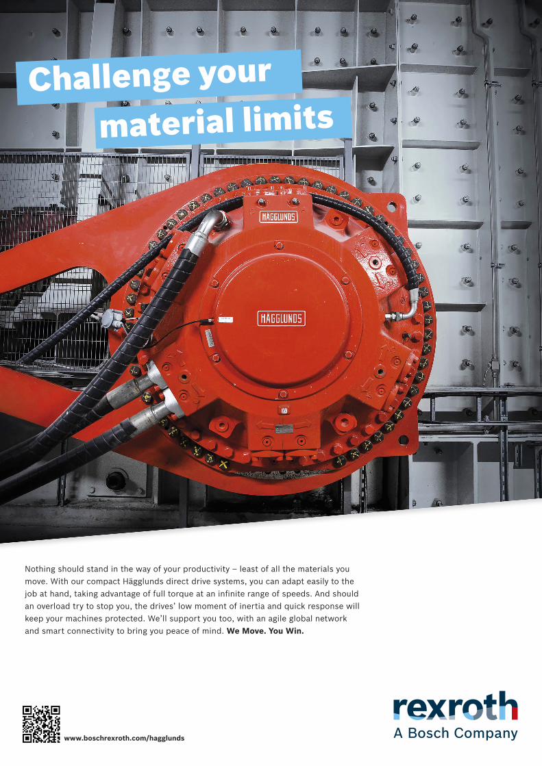
Challenge your material limits
Nothing should stand in the way of your productivity – least of all the materials youmove. With our compact Hägglunds direct drive systems, you can adapt easily to the
an overload try to stop you, the drives’ low moment of inertia and quick response willkeep your machines protected. We’ll support you too, with an agile global networkand smart connectivity to bring you peace of mind. We Move. You Win.
5March 2019 World Cement
NEWSNEWSEthiopian cement market shows strong growth
Ethiopian cement capacity grew at an annual average rate of 6.8% between 2013 and 2018, according to data from CW Group. The growth in capacity came as a result of the government’s fi ve year Growth and Transformation Plan, as well as federal incentives to attract local and international cement producers.
“Typically a heavy-consuming cement market, Ethiopian cement production had proven insuffi cient to meet demand until 2014, thus making Ethiopia an importing market,” CW Group Business Analyst, João Sobrinho, told World Cement. “Through this expansionist agenda, the domestic cement industry is increasingly becoming a net exporter and improving its international competitiveness”
Recent entrants into the market have included Dangote Cement, Derba, Messebo, and National Cement, while Abay Industrial Development Share Co. recently signed a contract with FLSmidth for the construction of a greenfi eld cement plant close to the city of Dejen.
Valued at E100 million, the contract will see the Danish engineering company construct a 5000 tpd plant, including design and engineering, full equipment supply, automation systems, installation, and commissioning, as well as training and extended supervision. It is expected that
the order will be completed in 2Q22.
“Ethiopia’s cement sector registered the highest CAGR in the last decade when compared to all East African markets,” Cement Business Research (CemBR) said in a recent research note. However, “after the buoyant trend of recent years, the market is expected to decline in 2018, when cement producers are tackling a long list of challenges: unfavourable supply-demand balance, higher cement prices, escalating production costs, low utilisation rates, social unrest, and a lack of foreign currency.”
“In the medium term, the domestic industry will have to focus on solving these setbacks, if it wishes to become an international cement force to be reckoned with,” agreed CW Group’s Sobrinho, who also mentioned a shortage of skilled workers as among the challenges facing the industry.
According to CemBR, the Ethiopian industry faces some of the highest energy costs in the region, while recent capacity additions have resulted in severe overcapacity in the country. The industry operated at around a 50% capacity utilisation rate according to both CemBR and CW Group. “It is now evident that the high-cost producers might have to shut down in order to give the industry a breather in terms of supply-demand balance,” concluded CemBR. “If the structure of the industry continued as it is today,
profi tability may suffer further for all participants.”
Despite these challenges, CW Group expects Ethiopia’s cement consumption to grow through 2023, driven by a strong economy – which is expected to be the fastest-growing in Sub-Saharan Africa, noted Sobrinho – and the government’s 2015 – 2025 Cement Industry Development Strategy.
“The cement market is a major concern for the government, which has scheduled a clear path for the industry up to 2025,” concluded CemBR. “Ethiopia’s demand projections rely heavily on the country’s economic stability, its diversifi cation, and the investments made in infrastructure and construction overall. The country’s ability and intention to deliver such growth is strong.”
Cemengal awarded contract by Kuwait ACICO Cement
Cemengal has been awarded a new contract for the supply of a second cement grinding station to ACICO Cement. The contract consists of a complete cement mill workshop and the main equipment to be included within the new contract is a 5200 kW ball mill fully engineered by Cemengal with all the peripheral equipment, as well as a fourth generation classifi er from Magotteaux XP4i-130 for high strength cements. Grinding capacity is projected to be 1 million tpy of cement and it is

DIARY
6 World Cement March 2019
NEWSNEWSexpected that the plant will be commissioned in 1H20.
The scope of the project includes full engineering and the complete supply of mechanical, process, electrical, and automation equipment, as well as steel manufacturing from the raw material handling areas up to the silo’s cement discharge. As well as the delivery of technology, site supervision, training, and commissioning activities are to be fully provided by Cemengal onsite.This is the second mill project to be awarded to Cemengal by ACICO Cement. The project is expected to aid the client in satisfying a growing demand for high-quality cements for major developments in Kuwait’s future infrastructures.
LafargeHolcim completes two acquisitions in US
LafargeHolcim has completed two bolt-on acquisitions, of Transit Mix Concrete Co. in Colorado, US, and Alfons Greten Betonwerk in Germany.
On 1 February 2019, LafargeHolcim acquired Transit Mix Concrete, a leading supplier of building materials in Colorado and a subsidiary of the Continental Materials Corp. It is hoped that this acquisition will strengthen LafargeHolcim’s position in a dynamic and growing building materials market in the US. The company will take ownership of Transit’s seven ready-mixed concrete plants and a sand quarry as part of the transaction. Transit has more than 180 employees.
In January 2019, LafargeHolcim acquired the precast and ready-mixed concrete business of Alfons Greten Betonwerk in Northern Germany. Operating one precast and one ready-mixed concrete plant, Greten is located in Lower Saxony. The acquisition is complementary to the company’s existing portfolio and will strengthen its existing Solutions and Products segment in the region. Greten employs around 100 people.
“In line with our ‘Strategy 2022 – Building for Growth’, these acquisitions will generate synergies with LafargeHolcim’s existing operations,” said Jan Jenisch. “With these further bolt-on acquisitions we are delivering on our commitment to accelerate growth in the ready-mixed concrete and aggregates segments. I am pleased to welcome all new employees to LafargeHolcim.”
Intercem awarded a number of new contracts
Following its successful projects in the Ivory Coast and Burkina Faso, Intercem has been granted a new order from Les Cimenteries de la Basse-Guinée in West Africa. The order comprises a cement grinding plant with a capacity of 0.5 million tpy, as well as a 12 000 t raw material shed, a hopper station, a packing plant, and a truck loading station in Kamsar, Guinea.
The 70 tph cement grinding plant includes a vertical roller
The UK Concrete Show20 – 21 March 2019Birmingham, UKwww.concreteshow.co.uk
A World Cement Webinar:What Value Can Digital Transformation Bring to Mining Companies?20 March 2019Register: bit.ly/WCTOSIsoft2
Africa CemenTrade Summit28 – 29 March 2019Marrakech, Morrocowww.cmtevents.com
China International Cement Industry Exhibition29 – 31 March 2019Hefei, Chinawww.cementtech.org
LafargeHolcim Forum for Sustainable Construction4 – 6 April 2019New Cairo, Egyptwww.lafargeholcim-foundation.org
bauma8 – 14 April 2019Munich, Germanywww.bauma.de
POWTECH9 – 11 April 2019Nuremberg, Germanywww.powtech.de
IEEE-IAS PCA Cement Industry Conference 201928 April – 2 May 2019St Louis, USAwww.cementconference.org
WWW.SCHEUCH.COM
Scheuch GmbH
Weierfing 68
4971 Aurolzmünster
Austria
Phone +43 / 7752 / 905 – 0
Fax +43 / 7752 / 905 – 65000
E-Mail [email protected]
As an international market leader in the ventilation and environmental technology sector,
Scheuch GmbH always keeps up to date with the latest industry technology.
The company provides trend-setting complete solutions for dust filtration and exhaust gas
cleaning for the entire cement production process. With the innovative emc, deconox and
xmercury systems, the Austria-based company is once again proving itself to be a global
pioneer in the industry.
FOR THE INDUSTRIAL MINERALS INDUSTRIES
SCHEUCHCLEAN SOLUTIONS
deconox
xmercury
emc

8 World Cement March 2019
NEWSNEWSmill with four rollers and an installed power of 1250 kW, a high-effi ciency separator, the transport of two 1000 t cement silos, and two truck loading stations for bulk cement.
The packing plant will include an eight-spout rotary packer and two loading stations for bagged cement. Intercem will also supply the sub-systems, electrical equipment, complete engineering, supervision of the erection, and commissioning.
All of the equipment will be delivered exclusively by European manufacturers.Groundbreaking will take place at the beginning of this month and fi rst cement production is scheduled 14 months after the contract comes into force.
Intercem has also been awarded a contract to supply a high-effi ciency ICS 143 separator and associated plant aggregates for a new cement plant in Russia. The separator has a capacity of 115 tph at 3000 cm2/g acc. to Blaine, with a total output of 258 tph. The volume fl ow of classifying air is 143 000 m3/hour. The scope of supply also includes engineering for the complete grinding plant, as well as supervision of the assembly and commissioning of the components included in the delivery.
Finally, the Lübeck cement plant has appointed Intercem to supply a silo unit consisting of four steel silos, with a capacity of 1200 m3 each. Also part of the scope of supply is bulk loading and complex cement conveying via air slides and bucket
elevators, leading over the complete area of the plant. Additional services include the engineering and associated plant components, such as a support structure, catwalks, filters, bucket elevators, return lines, and electrical equipment, as well as building application and dispatch automation.
Fives Group announces collaboration with CNBM
Fives Group has signed a cooperation agreement with CNBM, a leading Chinese group in cement production and plant construction. The agreement will involve cooperation on new global projects, such as plant upgrades, plant expansions, and new plants. “Fives’ technologies, such as its FCB Horomill grinding system, its FCB Pyro-line, and Pillard burners, have been recognised by CNBM for their performances in terms of electrical consumption and CO
2 emission,” the French
company said in a press release.
thyssenkrupp recognised as environmental leader
Non-governmental organisation, CDP (previously the Carbon Disclosure Project), has named thyssenkrupp as one of the world’s best companies in climate protection for the third year in a row. The Germany-based company achieved the highest possible score and was placed on
CDP’s A List. The list includes around 130 businesses and fi ve DAX companies.
CDP conducts the programme on behalf of more than 650 institutional investors, with assets worth more than US$90 trillion. Several thousand companies worldwide took part in the programme. The organisation also holds the world’s largest collection of corporate climate data and is regarded as a benchmark in the capital markets.
When it comes to climate protection, thyssenkrupp focuses on continuous efficiency improvement and long-term innovation leaps – both for its customers and its own processes, the company said in a press release. For example, with its oxyfuel technology, thyssenkrupp has developed a solution that efficiently captures CO
2
during cement production. The company has stated that its next step is the large-scale expansion of already proven technology.
“Despite the major global challenges, we are optimistic,” said Reinhold Achatz, Chief Technology Officer at thyssenkrupp. “With our resource-saving products and processes, we see climate change as an opportunity and are making our contribution to achieving the climate targets. The third award in a row shows we are right on track. We are convinced that there will not be just one technology. This is why we are open to new technologies and pursue different routes.”

KEY BENEFITS
State-of-the-art electronic weighing and control system
Customized design for filling unit, impeller profile, bag dimension and weight
Suitable for powder materials (gypsum, hydrated lime, cement etc.) or granulated products (mortars, ready mix, minerals etc.)
With the new design and technology the VENTOMATIC Lineamat inline packer meets
operational costs. VENTOMATIC inline packer is
VENTOMATIC®PACKAGING AND LOGISTICS
Lineamat™ new inline packer

Roaring lionRoaring lion 10
Yasmine Ghozzi, GlobalData, examines the construction output of Sub-Saharan Africa.
Sub-Saharan Africa (SSA) will be the fastest growing region in terms of construction output over the next fi ve years, according to GlobalData. Driven by high levels of investment
in infrastructure, total construction output in SSA will expand by an annual average of 6.7% in 2018 – 2022. SSA includes Angola, Cameroon, Ethiopia, Ghana, Kenya, Mozambique, Nigeria, South Africa, Tanzania, and

or laughing hyena?
11
Ethiopia. The region’s economy as a whole is on course for economic growth of 4.6% in 2019, up from 4.4% in 2018, and the longer-term outlook remains positive, with commodity prices improving and the global economy being in better shape. However, the picture is not all rosy, with Nigeria and South Africa – the region’s two largest economies – struggling to reclaim their growth potential. They are expected to grow in 2019 at 1.9% and 1.7%
respectively. There are areas that need careful monitoring: election cycles in Nigeria and South Africa are spawning policy uncertainty, while increased global trade tensions could result in a signifi cant slowdown in global trade that would likely reverberate across the region. In addition, monetary policy normalisation in the US could make access to external fi nancing diffi cult, particularly in those economies with inadequate reserve buffers.
12 World Cement March 2019
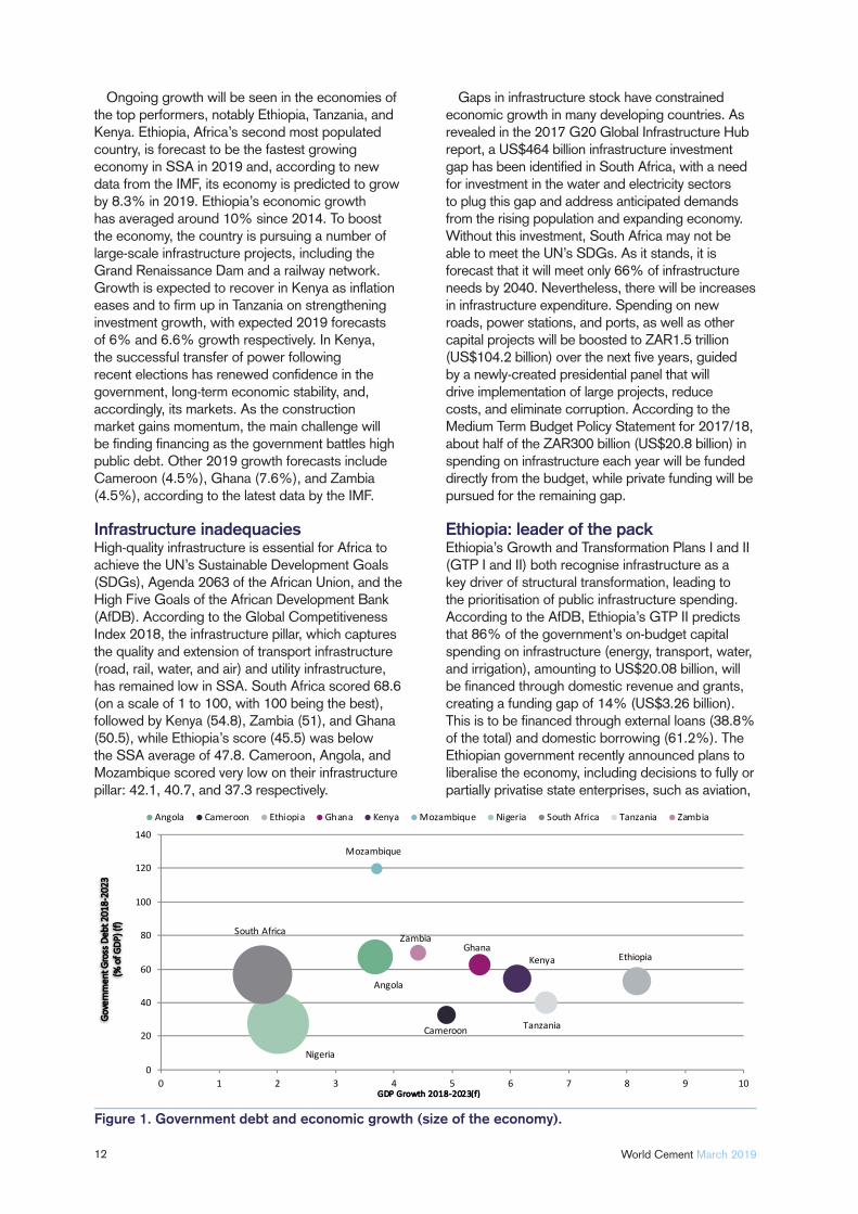
Ongoing growth will be seen in the economies of the top performers, notably Ethiopia, Tanzania, and Kenya. Ethiopia, Africa’s second most populated country, is forecast to be the fastest growing economy in SSA in 2019 and, according to new data from the IMF, its economy is predicted to grow by 8.3% in 2019. Ethiopia’s economic growth has averaged around 10% since 2014. To boost the economy, the country is pursuing a number of large-scale infrastructure projects, including the Grand Renaissance Dam and a railway network. Growth is expected to recover in Kenya as infl ation eases and to fi rm up in Tanzania on strengthening investment growth, with expected 2019 forecasts of 6% and 6.6% growth respectively. In Kenya, the successful transfer of power following recent elections has renewed confi dence in the government, long-term economic stability, and, accordingly, its markets. As the construction market gains momentum, the main challenge will be fi nding fi nancing as the government battles high public debt. Other 2019 growth forecasts include Cameroon (4.5%), Ghana (7.6%), and Zambia (4.5%), according to the latest data by the IMF.
Infrastructure inadequaciesHigh-quality infrastructure is essential for Africa to achieve the UN’s Sustainable Development Goals (SDGs), Agenda 2063 of the African Union, and the High Five Goals of the African Development Bank (AfDB). According to the Global Competitiveness Index 2018, the infrastructure pillar, which captures the quality and extension of transport infrastructure (road, rail, water, and air) and utility infrastructure, has remained low in SSA. South Africa scored 68.6 (on a scale of 1 to 100, with 100 being the best), followed by Kenya (54.8), Zambia (51), and Ghana (50.5), while Ethiopia’s score (45.5) was below the SSA average of 47.8. Cameroon, Angola, and Mozambique scored very low on their infrastructure pillar: 42.1, 40.7, and 37.3 respectively.
Gaps in infrastructure stock have constrained economic growth in many developing countries. As revealed in the 2017 G20 Global Infrastructure Hub report, a US$464 billion infrastructure investment gap has been identifi ed in South Africa, with a need for investment in the water and electricity sectors to plug this gap and address anticipated demands from the rising population and expanding economy. Without this investment, South Africa may not be able to meet the UN’s SDGs. As it stands, it is forecast that it will meet only 66% of infrastructure needs by 2040. Nevertheless, there will be increases in infrastructure expenditure. Spending on new roads, power stations, and ports, as well as other capital projects will be boosted to ZAR1.5 trillion (US$104.2 billion) over the next fi ve years, guided by a newly-created presidential panel that will drive implementation of large projects, reduce costs, and eliminate corruption. According to the Medium Term Budget Policy Statement for 2017/18, about half of the ZAR300 billion (US$20.8 billion) in spending on infrastructure each year will be funded directly from the budget, while private funding will be pursued for the remaining gap.
Ethiopia: leader of the packEthiopia’s Growth and Transformation Plans I and II (GTP I and II) both recognise infrastructure as a key driver of structural transformation, leading to the prioritisation of public infrastructure spending. According to the AfDB, Ethiopia’s GTP II predicts that 86% of the government’s on-budget capital spending on infrastructure (energy, transport, water, and irrigation), amounting to US$20.08 billion, will be fi nanced through domestic revenue and grants, creating a funding gap of 14% (US$3.26 billion). This is to be fi nanced through external loans (38.8% of the total) and domestic borrowing (61.2%). The Ethiopian government recently announced plans to liberalise the economy, including decisions to fully or partially privatise state enterprises, such as aviation,
Figure 1. Government debt and economic growth (size of the economy).

13March 2019 World Cement
FLYINGBELT, CABLE CRANES, MATERIAL ROPEWAYS, CUSTOMIZED CABLEWAYS. Since 1861 reliability, performance and innovation are our values, Agudio a leading brand in engineering and construction of rope-hauled material transportation systems.
AGUDIO: INNOVATION THAT SHORTEN DISTANCES.
Flying over obstacles, since 1861
14 World Cement March 2019
energy, telecommunication, and manufacturing. Under this plan, foreign and domestic investors can buy minority stakes in sectors that were previously deemed to be off limits to private enterprises. This announcement represents a major policy shift by the government, as the new leadership seeks a new direction for the economy, while maintaining its strong public state ideology.
Tanzania’s long-term development visionTanzania’s poor infrastructure remains a major impediment to the growth and development of its economy, as well as of the private sector. Tanzania’s second Five Year Development Plan 2016/2017 – 2020/2021 (FYDP II) emphasises industrialisation, with infrastructure and transportation development set to act as an important role in expanding the business environment and attracting new investment. Public fi nancing for FYDP II is projected to be around US$3 billion/year over the fi ve years. One primary development target is to ameliorate the country’s quality of infrastructure, which rank 119th out of 139 countries – as per the World Economic Forum’s Global Competitiveness Report 2018 – to the top 100 by 2025/2026. The country also has several multi-year master plans and programmes in place, including the transport sector investment programme, the Tanzania Ports Master Plan (2008 – 2028), the civil aviation master plan, and the Tanzania power sector master plan (2006 – 2031).
Kenya’s infrastructure challenge The government in Kenya is focusing on improving transport infrastructure, in terms of both domestic and international links, and is striving to attract new investment by expanding the port, road, and rail networks. The AfDB estimates that Kenya’s fi nancing needs are likely to be between US$7.4 billion/year and US$8.3 billion/year, which puts the country’s fi nancing gap at US$5 billion/year; the transport sector’s fi nancing need alone is estimated at between US$3 billion/year and US$3.5 billion/year over 10 years. With public debt standing at 57% of GDP, this defi cit cannot be met by public resources. The country needs to mobilise the private sector and local funding to fi nance infrastructure needs. The World Bank estimates that increasing infrastructure fi nancing could improve Kenya’s per capita GDP growth rate by three percentage points.
Tackling Nigeria’s infrastructure defi citExtensive reforms in Nigeria are ongoing in an effort to plug infrastructure gaps, improve welfare, and accelerate economic development. Signifi cantly, the federal government has developed an ambitious 30 year National Integrated Infrastructure Master Plan (NIIMP) 2014 – 2044. The NIIMP, which provides fi nancing estimates in different sectors, seeks to close the country’s infrastructure gap to transform the economy. The effect of the poor state of infrastructure is more serious in the energy sector, where Nigeria’s per capita energy consumption stands at 122.5 kWh/year compared to 4465 kWh/year in South Africa. About 101 million people do not have access to the electricity grid, relying on polluting light sources, such as kerosene lamps. The main reason for low access is inadequate energy generation and capacity, as well as ineffi ciency in the distribution channels in the country, leading to recurrent power shortcuts. It is estimated that the energy sector, particularly electricity, operates below 50% of its potential, due to untapped productive sources. Water resources are not effectively used for generating electricity and other uses in Nigeria. It is estimated that the country needs about US$3 trillion over the next 30 years to bridge the infrastructure gap.
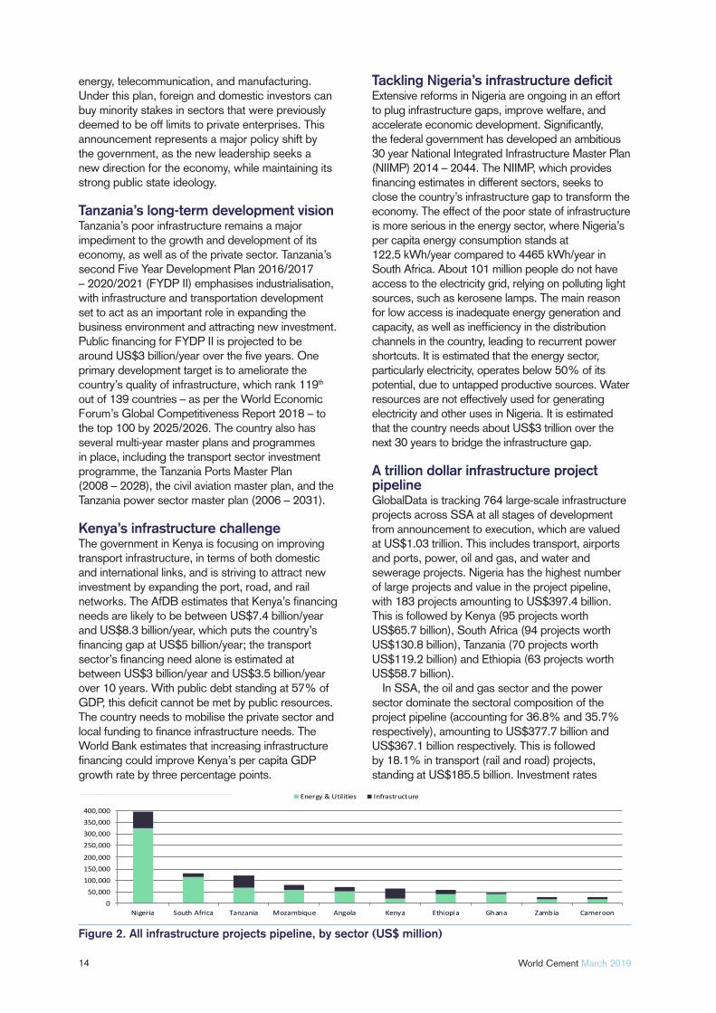
A trillion dollar infrastructure project pipelineGlobalData is tracking 764 large-scale infrastructure projects across SSA at all stages of development from announcement to execution, which are valued at US$1.03 trillion. This includes transport, airports and ports, power, oil and gas, and water and sewerage projects. Nigeria has the highest number of large projects and value in the project pipeline, with 183 projects amounting to US$397.4 billion. This is followed by Kenya (95 projects worth US$65.7 billion), South Africa (94 projects worth US$130.8 billion), Tanzania (70 projects worth US$119.2 billion) and Ethiopia (63 projects worth US$58.7 billion).
In SSA, the oil and gas sector and the power sector dominate the sectoral composition of the project pipeline (accounting for 36.8% and 35.7% respectively), amounting to US$377.7 billion and US$367.1 billion respectively. This is followed by 18.1% in transport (rail and road) projects, standing at US$185.5 billion. Investment rates
Figure 2. All infrastructure projects pipeline, by sector (US$ million)
in transport infrastructure have been increasing, thanks to major continental initiatives such as the Program for Infrastructure Development in Africa. This is a strategic initiative that has the buy-in of all African countries, for mobilising resources to transform Africa through modern infrastructure. Its 51 cross-border infrastructure projects comprise more than 400 actionable sub-projects across four main infrastructure sectors: energy, transport, trans-boundary water, and information and communications technology.
Transport and energy supply and access are essential to the region’s development. As a result, high ticket projects are currently underway, including the construction of the 3300 km US$21.5 billion standard gauge railway, a high capacity network linking Kenya, Uganda, Rwanda, and South Sudan, to be completed in 2021. On the energy side, the US$10.4 billion Medupi coal-fi red power plant project in the Limpopo province in South Africa is a 4800 MW plant that will be the largest dry-cooled power station in the world, aiming to provide much needed power to a growing population over the long term.
Public private partnershipsAcross the region, governments have paved the way for public private partnerships (PPPs) to fund a large proportion of projects in the pipeline. According to GlobalData, 38% of the total project pipeline is
being funded by various joint fi nancing arrangements between the public and private sector, while 24.1% of tracked projects are solely publicly funded. PPPs show the importance of the private sector in helping governments to provide critical infrastructure.
Investment from China will remain vitalChinese engineering groups, thanks to government support in the form of concessionary loans from the Export-Import Bank of China, have dominated the SSA building boom and will continue to do so. China has made numerous investments across the region, encompassing railways, highways, ports, oil and gas fi elds, and power plants. Investment from US and European countries is mostly focused on energy and power. According to the latest data from the Infrastructure Consortium for Africa, China remains by far the single largest investor in African infrastructure projects; between 2011 and 2016, Chinese investment averaged US$12 billion/year. African countries remain open to cooperation with China for the development of infrastructure projects under the Belt and Road Initiative. The region’s construction boom has also attracted an increasing number of cement makers. For example, the Tanzanian government announced in 2017 that three cement companies planned to invest about US$9.2 billion in order to increase production capacity.
www.bauma-geda.de
16 World Cement March 2019
There will be substantial investment in energy and utilities infrastructure in the coming fi ve years, with the current pipeline of projects amounting to US$754.7 billion. More than 200 million people in SSA are off the grid, accounting for around 80% of its population. It is not only insuffi cient power generation that stands in the way of the development of African countries, but also the absence of inter-connectors to supply power across borders. Africa lacks transmission capacity, noting that the combined length of transmission in 38 countries in Africa, totalling 112 196 km, is still shorter than Brazil’s 125 640 km network.
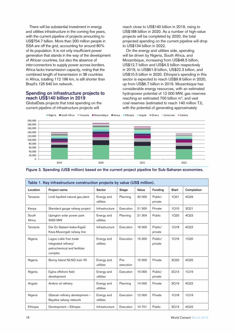
Spending on infrastructure projects to reach US$140 billion in 2019GlobalData projects that total spending on the current pipeline of infrastructure projects will
reach close to US$140 billion in 2019, rising to US$188 billion in 2020. As a number of high-value projects will be completed by 2020, the total projected spending on the current pipeline will drop to US$134 billion in 2022.
On the energy and utilities side, spending will be driven by Nigeria, South Africa, and Mozambique, increasing from US$48.5 billion, US$12.7 billion and US$4.5 billion respectively in 2019, to US$61.8 billion, US$22.3 billion, and US$10.5 billion in 2020. Ethiopia’s spending in this sector is expected to reach US$9.8 billion in 2020, up from US$6.7 billion in 2019. Mozambique has considerable energy resources, with an estimated hydropower potential of 12 000 MW, gas reserves reaching an estimated 700 billion m3, and vast coal reserves (estimated to reach 140 million TJ), with the potential of generating approximately
Table 1. Key infrastructure construction projects by value (US$ million).
Location Project name Sector Stage Value Funding Start Completion
Tanzania Lindi liquifi ed natural gas plant Energy and
utilities
Planning 30 000 Public/
private
1Q21 4Q29
Kenya Standard gauge railway project Infrastructure Execution 21 500 Private 1Q15 3Q21
South
Africa
Upington solar power park
5000 MW
Energy and
utilities
Planning 21 304 Public 1Q20 4Q23
Tanzania Dar Es Salaam-Isaka-Kigali/
Keza-Musongati railway line
Infrastructure Execution 16 000 Public/
private
1Q18 4Q22
Nigeria Lagos Lekki free trade
integrated refi nery/
petrochemical and fertilizer
complex
Energy and
utilities
Execution 15 000 Public/
private
1Q16 1Q20
Nigeria Bonny Island NLNG train VII Energy and
utilities
Pre-
execution
15 000 Private 3Q20 4Q25
Nigeria Egina offshore fi eld
development
Energy and
utilities
Execution 15 000 Public/
private
2Q13 1Q19
Angola Ambriz oil refi nery Energy and
utilities
Planning 14 000 Private 3Q19 4Q22
Nigeria Gbarain refi nery development –
Bayelsa railway network
Energy and
utilities
Execution 12 000 Private 1Q18 1Q19
Ethiopia Development – Ethiopia Infrastructure Execution 10 701 Public 3Q13 4Q22
Figure 3. Spending (US$ million) based on the current project pipeline for Sub-Saharan economies.
17March 2019 World Cement
500 MW and 5000 MW respectively. Investment in infrastructure is an important aspect for enabling GDP growth and more diversifi ed economic and private sector activity.
In terms of transport infrastructure, spending will be driven by Nigeria, Tanzania, and Kenya, in 2020 reaching US$11.7 billion, US$9.1 billion, and US$8.4 billion. respectively. The Mombasa-Nairobi Standard Gauge Railway is the largest and most expensive infrastructure project ever undertaken in Kenya. The US$21.5 billion project is 480 km of modern construction that traverses mountain ranges, wetlands, and national parks from the Indian Ocean port of Mombasa directly into the interior of East Africa and Kenya’s capital, Nairobi. Mombasa is the largest sea port in East Africa and its key trade gateway.
Challenges remain Challenges in the region remain vast and deeply embedded. For example, little progress has been made in per capita electricity-generating capacity in over two decades. Only 35% of the population has access to electricity, with rural access rates less than one-third of those in an urban environment. Transport infrastructure is likewise lagging, with SSA being the only region in the world where road density has declined over the past 20 years. Closing the infrastructure quantity and quality gap relative to the best performers in the world could increase growth of GDP per capita by 2.6% per year, according to the World Bank. The largest potential growth benefi ts would come from closing the gap in electricity-generating capacity.
There are also factors that hinder infrastructure fi nancing in the region, including higher transaction costs, inadequate availability of bankable projects, permits and licenses required, and the multi-governmental agencies and institutions that investors must deal with in a typical capital project. There are obstacles related to limited local capacity for project preparation and tender (fi nancial, technical, legal, and environmental feasibility). Owing to these challenges, many projects proposed by governments are not moving ahead. Considerable effort has been made to incorporate the private sector in high ticket projects, but several grey areas and pitfalls still remain. Public-private partnerships in SSA remain a very small market, with projects concentrated in only a few countries – namely, South Africa, Nigeria, and Kenya. Partnerships are a means to fund ongoing developments in the region and could relieve states from the rising debt levels associated with mega projects, such as railways.
About the authorYasmine Ghozzi is an Economist at GlobalData.
Thorwesten Vent are your experts in explosion venting and pressure shock resistant design and construction. Thorwesten Vent offers explosion protection-related consultancy for the planning of new as well as the correction of existing grinding facilities for solid fuels.
We provide for your safety!
for industries typically using coal, lignite, pet coke and secondary fuels
Explosion protection
Highly effi cient self-reclosing explosion vents
Customized safety solutions comprising
engineering and hardware supply
Professional consulting and assistance
We provide for your safety
THORWESTEN VENT GmbHDaimlerring 39 • 59269 Beckum / Germany
Phone: +49(0)2521/[email protected]
www.thorwesten.com

A Land of Opportunity?
18

19
Dom Pavlopoulos and Claudia Stefanoiu, Cement Business Research, provide a market analysis of the cement industries in East Africa.
This article offers a regional review of fi ve East African cement industries, based on a recently published report by Cement Business Research (CemBR).
CemBR is a research fi rm addressing the global cement sector. The following markets are assessed in this regional report: Ethiopia, Kenya, Mozambique, Tanzania, and Uganda.
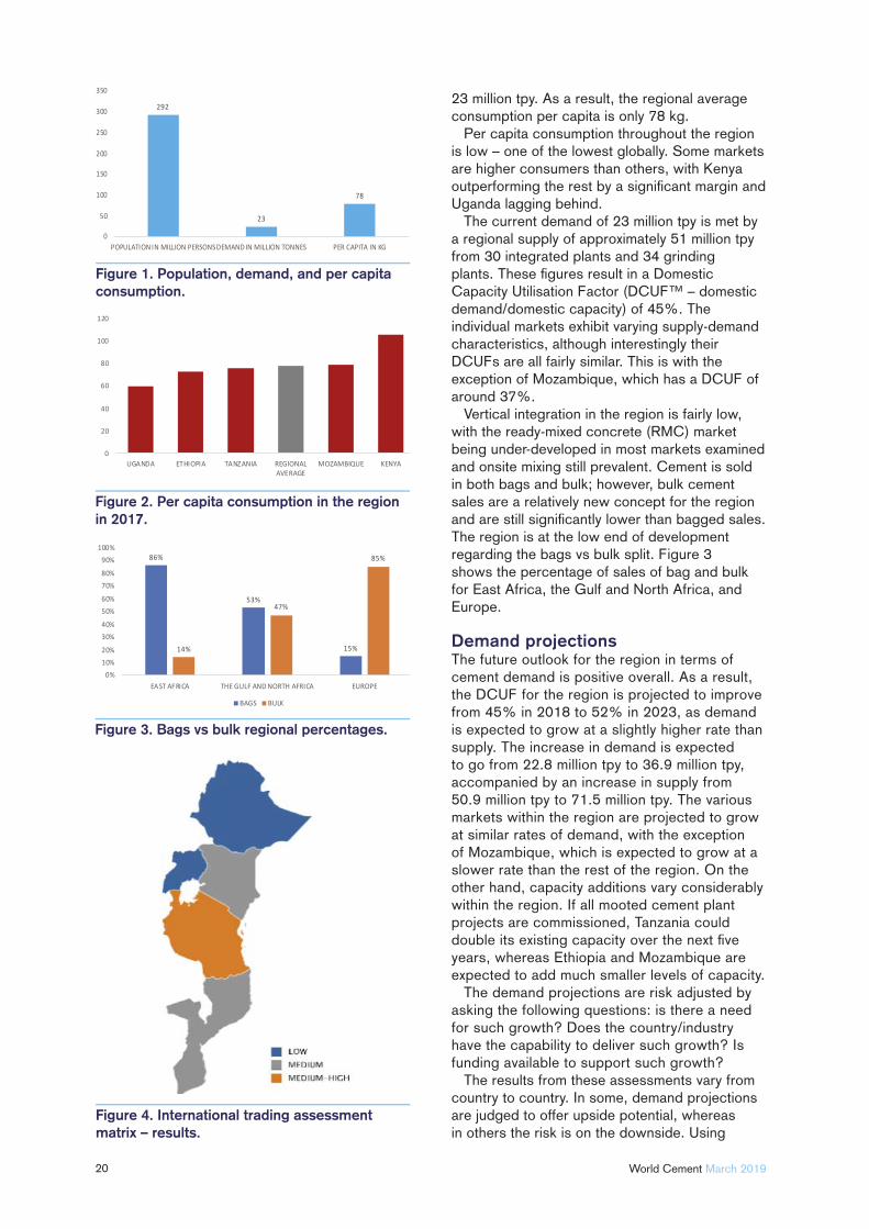
The current situationThe region has one of the lowest cement consumptions per capita globally, while exhibiting strong urbanisation growth. This offers an opportunity for the region to grow signifi cantly, assuming that certain conditions are satisfi ed.
Currently, the region has a population of 292 million and cement demand of just
20 World Cement March 2019
23 million tpy. As a result, the regional average consumption per capita is only 78 kg.
Per capita consumption throughout the region is low – one of the lowest globally. Some markets are higher consumers than others, with Kenya outperforming the rest by a signifi cant margin and Uganda lagging behind.
The current demand of 23 million tpy is met by a regional supply of approximately 51 million tpy from 30 integrated plants and 34 grinding plants. These fi gures result in a Domestic Capacity Utilisation Factor (DCUF™ – domestic demand/domestic capacity) of 45%. The individual markets exhibit varying supply-demand characteristics, although interestingly their DCUFs are all fairly similar. This is with the exception of Mozambique, which has a DCUF of around 37%.
Vertical integration in the region is fairly low, with the ready-mixed concrete (RMC) market being under-developed in most markets examined and onsite mixing still prevalent. Cement is sold in both bags and bulk; however, bulk cement sales are a relatively new concept for the region and are still signifi cantly lower than bagged sales. The region is at the low end of development regarding the bags vs bulk split. Figure 3 shows the percentage of sales of bag and bulk for East Africa, the Gulf and North Africa, and Europe.
Demand projectionsThe future outlook for the region in terms of cement demand is positive overall. As a result, the DCUF for the region is projected to improve from 45% in 2018 to 52% in 2023, as demand is expected to grow at a slightly higher rate than supply. The increase in demand is expected to go from 22.8 million tpy to 36.9 million tpy, accompanied by an increase in supply from 50.9 million tpy to 71.5 million tpy. The various markets within the region are projected to grow at similar rates of demand, with the exception of Mozambique, which is expected to grow at a slower rate than the rest of the region. On the other hand, capacity additions vary considerably within the region. If all mooted cement plant projects are commissioned, Tanzania could double its existing capacity over the next fi ve years, whereas Ethiopia and Mozambique are expected to add much smaller levels of capacity.
The demand projections are risk adjusted by asking the following questions: is there a need for such growth? Does the country/industry have the capability to deliver such growth? Is funding available to support such growth?
The results from these assessments vary from country to country. In some, demand projections are judged to offer upside potential, whereas in others the risk is on the downside. Using
Figure 1. Population, demand, and per capita consumption.
Figure 2. Per capita consumption in the region in 2017.
Figure 3. Bags vs bulk regional percentages.
Figure 4. International trading assessment matrix – results.
Ethiopia as an example, the country’s cement market is expected to grow signifi cantly over the next fi ve years on the back of robust economic growth driving a clear need for increasing cement consumption. However, there are issues facing the capability to deliver the expected demand, as well as issues surrounding the required funding. These issues are detailed in the report.
International Trading Assessment Matrix In similarity to other regions around the world, the last few years of capacity additions have led to signifi cant oversupply. As a result of this, the report assesses the ability and potential of each market to export its excess capacity. For this purpose, the report examines the International Trading Assessment Matrix (ITAM™) tool. This tool is also applied to imports where needed (e.g. clinker and coal imports). The criteria examined in ITAM are the following:
Trade supporting legislation.Port infrastructure and capacity.Existence of coastal plants.Cost of haulage.Economics of trading.
The individual markets in this report have varying ITAM scores for several reasons. For
example, Uganda’s ITAM is lower than others in the region, due to the fact that it is landlocked and therefore unable to benefi t from seaborne trade. Kenya, on the other hand, has a higher ITAM score, driven by its streamlined access to clinker and coal imports. However, when exporting, Kenyan cement companies are restricted to land transportation, which limits its competitiveness when compared to cheaper Asian imports or regional competitors, who report better economics of trading overall.
An overall assessment was made for each country. Figure 4 shows a graphical representation for the ITAM fi ndings for the region.
The DCUF and ITAM combined examine the propensity and ability of each market to export/import. In addition, CemBR assesses each industry’s existing or potential destination markets to see whether exporting excess capacity is a viable solution.
In many cases in this region, exporting large quantities of cement is challenging. There is an overall excess capacity in the region, which implies that defi cit destination markets in the vicinity have dried out. Furthermore, as a result of the regional excess capacity, all exporting markets face fi erce competition from traditional exporters, as well as each other. As a result, exporting may prove diffi cult for the region.
Cement Industry Solutions
4B Components Ltd. • Morton, IL USA • +1 309-698-5611 • www.go4b.com/usa
Engineering Solutions Since 1888
E l eva t o r Bu c ke t s & Bo l t sS t e e l Co r d B e l t in gD r a g Co nveyo r Cha inPreven t a t i ve M a in t enanc eM o n i t o r in g S ys t e m s & S e n so r s
4BComponentsLimited
22 World Cement March 2019
Industry Structure Dynamics Industry Structure Dynamics (ISD™) examine in detail the nature of participants, the consolidation index of the industry, and the cost structure and dynamics of the industry. The fi ndings of the ISD are informative and insightful. The nature of participants determines their behaviour in a given market, whereas a highly consolidated industry provides useful messages regarding prices going forward. The industry cost structure and dynamics show the current situation of the industry in terms of technology, improvement potential, and industry profi tability. Some of the regional fi ndings of ISD are shown in Figure 5.
The nature of participants provides some very useful insights into each industry. For example, the prevalence of international players should signify a high level of vertical integration. With international players representing 35% of regional capacity, higher levels of vertical integration would be expected. However, due to the unregulated and underdeveloped RMC market, cement producers have chosen to eschew vertical integration, opting to take control of their distribution channels instead.
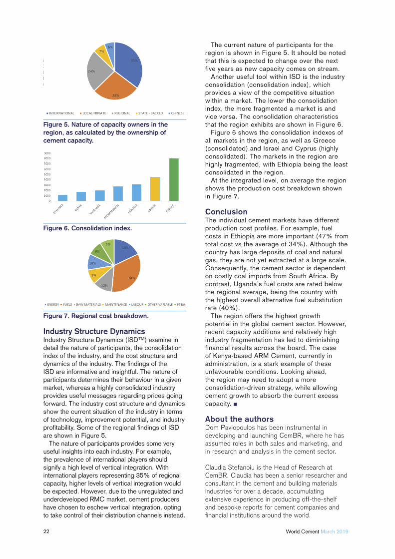
The current nature of participants for the region is shown in Figure 5. It should be noted that this is expected to change over the next five years as new capacity comes on stream.
Another useful tool within ISD is the industry consolidation (consolidation index), which provides a view of the competitive situation within a market. The lower the consolidation index, the more fragmented a market is and vice versa. The consolidation characteristics that the region exhibits are shown in Figure 6.
Figure 6 shows the consolidation indexes of all markets in the region, as well as Greece (consolidated) and Israel and Cyprus (highly consolidated). The markets in the region are highly fragmented, with Ethiopia being the least consolidated in the region.
At the integrated level, on average the region shows the production cost breakdown shown in Figure 7.
ConclusionThe individual cement markets have different production cost profiles. For example, fuel costs in Ethiopia are more important (47% from total cost vs the average of 34%). Although the country has large deposits of coal and natural gas, they are not yet extracted at a large scale. Consequently, the cement sector is dependent on costly coal imports from South Africa. By contrast, Uganda’s fuel costs are rated below the regional average, being the country with the highest overall alternative fuel substitution rate (40%).
The region offers the highest growth potential in the global cement sector. However, recent capacity additions and relatively high industry fragmentation has led to diminishing financial results across the board. The case of Kenya-based ARM Cement, currently in administration, is a stark example of these unfavourable conditions. Looking ahead, the region may need to adopt a more consolidation-driven strategy, while allowing cement growth to absorb the current excess capacity.
About the authorsDom Pavlopoulos has been instrumental in developing and launching CemBR, where he has assumed roles in both sales and marketing, and in research and analysis in the cement sector.
Claudia Stefanoiu is the Head of Research at CemBR. Claudia has been a senior researcher and consultant in the cement and building materials industries for over a decade, accumulating extensive experience in producing off-the-shelf and bespoke reports for cement companies and fi nancial institutions around the world.
Figure 7. Regional cost breakdown.
Figure 5. Nature of capacity owners in the region, as calculated by the ownership of cement capacity.
Figure 6. Consolidation index.

23
The The Bigger Bigger Picture Picture Mark Mutter and Lawrie Evans, JAMCEM Consulting, discuss how to
optimise the cement, as well as the mill.
There are many articles that have been written about the optimisation of cement milling systems, generally with the focus being on increasing throughput and
decreasing specifi c power consumption. But what many of these articles fail to consider is that, in optimising the mill, the fi nal product quality also has
to be optimised. Having an effi cient milling system in terms of power consumption can be a competitive advantage for the plant but, if the quality of the cement is inferior to the others in the marketplace – especially in an over-capacity market, then the low cost of production is much less of an advantage if the potential customers will not buy the cement.
24 World Cement March 2019
Alternatively, the customer may buy the cement but demand a lower price stating, “we have to use a higher volume of cement to get the concrete strengths required,” damaging the plant profi t and loss.
This article will look at the quality aspects of cement milling and how plant profi t and loss, combined with poor product quality, can be affected by poor milling effi ciency.
Getting the basics rightMill audits are an essential part of the plant testing schedule and should be done on a regular basis, with a process focus. This means that the tests should not just be about measuring the thickness of liners and diaphragms in order to assess when they should be replaced. The process focus must consider the effi ciency of the grinding in the mill. This depends on many factors, including the following:
The lift from the liners given to the media charge.
The quantity of media in each of the chambers, to optimise the grinding effi ciency or achieve maximum mill output, whichever is the required outcome.
The right proportion of each size of media in the chamber.
The effi ciency of any classifying liner installed.
Void fi lling rates. The adequacy of the ventilation of the mill. The effectiveness of any water injection
systems. The overall mill automatic control system. The effectiveness of any grinding aids used.
All of these basics need to be kept in optimum state in order for the milling system to operate correctly. Not noted above, however, is the impact that the cement mill separator can have both on the overall effi ciency of the system, and
more importantly on the fi nal product quality. It is often forgotten that the separator is a critical part of the cement milling system and the cement mill separator is discussed in more detail in the following section.
The Rosin-Rammler curve As the name would suggest, the key function of the separator is to send out of the system as much as possible of the cement that is fine enough to be considered as final product, and to send the coarse material back to the cement mill. There will never be perfect separation, but it is important to maintain this split between fine and coarse particles as efficiently as possible. If there are too many coarse particles going to the final product, the final strength of the cement that is produced will drop, which will be to the detriment of sales. Comparatively, if too many fines are sent back to the mill, these particles will be over-ground on their second pass through the mill, resulting in inefficient grinding.
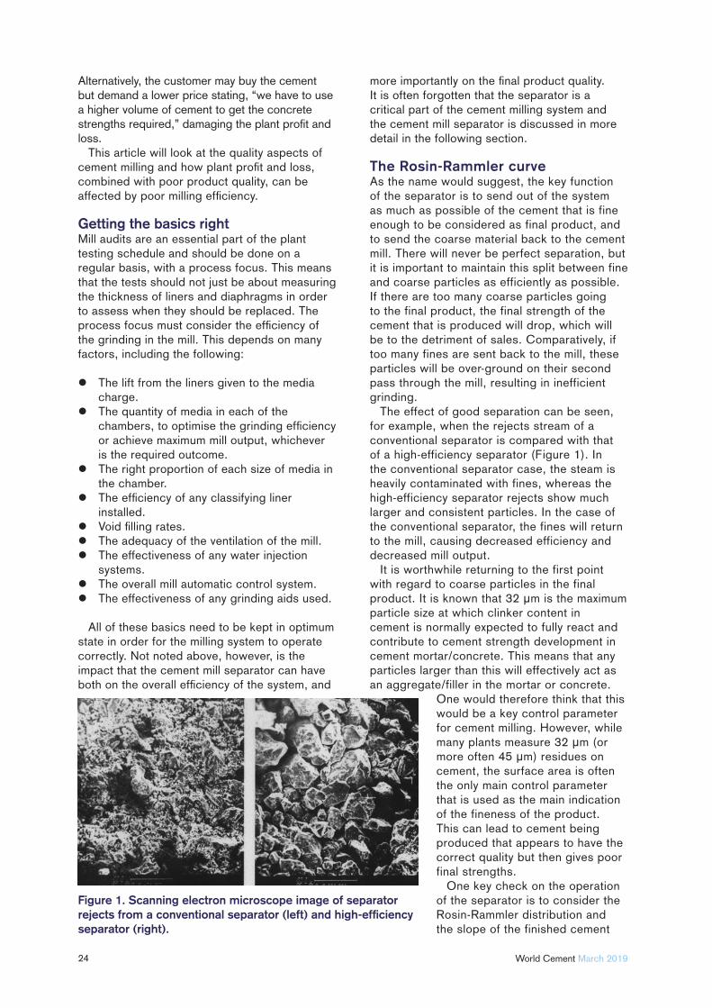
The effect of good separation can be seen, for example, when the rejects stream of a conventional separator is compared with that of a high-efficiency separator (Figure 1). In the conventional separator case, the steam is heavily contaminated with fines, whereas the high-efficiency separator rejects show much larger and consistent particles. In the case of the conventional separator, the fines will return to the mill, causing decreased efficiency and decreased mill output.
It is worthwhile returning to the first point with regard to coarse particles in the final product. It is known that 32 μm is the maximum particle size at which clinker content in cement is normally expected to fully react and contribute to cement strength development in cement mortar/concrete. This means that any particles larger than this will effectively act as an aggregate/filler in the mortar or concrete.
One would therefore think that this would be a key control parameter for cement milling. However, while many plants measure 32 μm (or more often 45 μm) residues on cement, the surface area is often the only main control parameter that is used as the main indication of the fineness of the product. This can lead to cement being produced that appears to have the correct quality but then gives poor final strengths.
One key check on the operation of the separator is to consider the Rosin-Rammler distribution and the slope of the finished cement
Figure 1. Scanning electron microscope image of separator rejects from a conventional separator (left) and high-effi ciency separator (right).
ADVANCED PROCESS CONTROLINNOVATIVE MEASUREMENTS
KIMA Process Control GmbHGuestener Str. 72 / 52428 Juelich / Germany / Phone: +49 2463 9967 0
For further information please visit www.kima-process.de
KILNCOOLER
expansion of kiln‘s operation timereduced mechanical tensionenergy savings
PRECISE CONTROLLED WATER COOLING OF KILN SHELL
GRINDING OPTIMIZATION USING FILL LEVEL MEASUREMENT
SMARTFILL™ & MILLMASTER
increased production
less wear out
––––
–––
26 World Cement March 2019
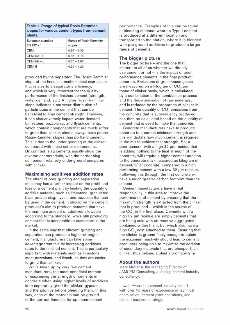
produced by the separator. The Rosin-Rammler slope of the fines is a mathematical expression that relates to a separator’s efficiency, and which is very important for the quality performance of the finished cement (strength, water demand, etc.) A higher Rosin-Rammler slope indicates a narrower distribution of particle sizes in the cement that can be beneficial to final cement strength. However, it can also adversely impact water demand. Limestone, pozzolanic, and flyash cements, which contain components that are much softer to grind than clinker, almost always have poorer Rosin-Rammler slopes than portland cement. This is due to the under-grinding of the clinker compared with these softer components. By contrast, slag cements usually show the reverse characteristic, with the harder slag component relatively under-ground compared with clinker.
Maximising additives addition ratesThe effect of poor grinding and separation efficiency has a further impact on the profit and loss of a cement plant by limiting the quantity of additive material, such as limestone, granulated blastfurnace slag, flyash, and pozzolan that can be used in the cement. It should be the cement producer’s aim to produce cements that have the maximum amount of additives allowable according to the standard, while still producing cement that is acceptable to customers in the market.
In the same way that efficient grinding and separation can produce a higher strength cement, manufacturers can take some advantage from this by increasing additions rates to the finished cement. This is particularly important with materials such as limestone, most pozzolans, and flyash, as they are easier to grind than clinker.
While taken up by very few cement manufacturers, the most beneficial method of maximising the strength of cements in concrete when using higher levels of additives is to separately grind the clinker, gypsum, and the additive before blending them. In this way, each of the materials can be ground to the correct fineness for optimum cement
performance. Examples of this can be found in blending stations, where a Type I cement is produced at a different location and transported to the station, where it is blended with pre-ground additives to produce a larger range of cements.
The bigger pictureThe bigger picture – and the one that matters to all of us whether we directly use cement or not – is the impact of poor performance cements in the final product: concrete. Emissions of greenhouse gases are measured on a kilogram of CO
2 per
tonne of clinker basis, which is calculated by a combination of the combustion process and the decarbonisation of raw materials, and is reduced by the proportion of clinker in cement. The quantity of CO
2 emissions from
the concrete that is subsequently produced can then be calculated based on the quantity of cement that is used to make that concrete.
Concrete manufacturers have to produce concrete to a certain minimum strength and this will dictate how much cement is required in the mix to achieve that strength. So, a poor cement, with a high 32 μm residue that is adding nothing to the final strength of the concrete, will require a higher cement addition to the concrete mix (measured as kilogram of cement/m3 of concrete) compared to a high performing cement with a low 32 μm residue. Following this through, the first concrete will have a much greater carbon footprint than the second.
Cement manufacturers have a real responsibility in this area to improve the performance of cement by ensuring that the maximum strength is extracted from the clinker that is produced − which is the source of the CO
2 in the first place. Cements with a
high 32 μm residue are simply cements that are being sold with un-reactive aggregates contained within them, but which also have a high CO
2 cost attached to them. Ensuring that
the clinker is ground finely enough to obtain the maximum reactivity should lead to cement producers being able to maximise the addition of secondary materials that are cheaper than clinker, thus helping a plant’s profitability.
About the authorsMark Mutter is the Managing Director of JAMCEM Consulting, a leading cement industry consultancy.
Lawrie Evans is a cement industry expert with over 40 years of experience in technical optimisation, cement plant operations, and cement business strategy.
Table 1. Range of typical Rosin-Rammler slopes for various cement types from cement plants.European standard
EN 197 – 1
Range of Rosin-Rammler
slopes
CEM I 0.95 1.30
CEM II/A L 0.85 1.15
CEM II/B L 0.75 1.05
CEM III 0.90 1.20
27
P. Ponnusamy, Mukesh K. Mishra, Praseeja Shankaran, Soumen Saha, and S.P. Pandey, Dalmia Cement Research Centre, explain how to enhance the functional features of geopolymer cement.
Ordinary portland cement (OPC) and blended portland cement (BPC) are conventionally used as primary binders from the beginning of construction activities. However, the
environmental impact and emission of greenhouse gases, such as carbon dioxide (CO
2), from the cement industry
has widely affected the environment, with increasing infrastructure development worldwide. It is due to this demand that the production of cement as a binder in concrete will continue to increase. However, sustainable construction materials may substitute cement in the future, due to the go green revolution. As a result of natural resource depletion and CO
2 emission issues in cement
manufacturing, the need to switch over to alternative binders becomes important.
28 World Cement March 2019
However, the alternate binding materials that replace cement should meet certain criteria, such that they should be eco-friendly, readily available, and cost effective. The durability and strength of the set mass needs to be as good as that of cement. Geopolymer is a type of binder produced by the polymeric chain of reactions of alkali activators with industrial byproduct materials, such as flyash (class C and class F) and slag. This includes blastfurnace slag, granulated blastfurnace slag, and ground granulated blastfurnace slag (GGBS).1,2
Flyash is one of the major sources of silica (SiO
2) and alumina (Al
2O
3) in geopolymers.
Flyash is classified to class C or class F based on its chemical composition, where the main difference is the amount of calcium. Class C flyash has a higher content of calcium than that of class F flyash. A higher content of calcium oxide (CaO) in the flyash results in a higher compressive strength of the geopolymer, due to the formation of hydrated products, such as calcium silicate hydrate (CSH).3 However, in these conditions, the workability of the geopolymer is found to decrease noticeably (in less than 3 min.), due to the high reactivity of class C flyash. Hence, class F flyash is selected as a good raw material for geopolymers, due to its lower reactivity rate, which leads to a proper workability and reduced water demand.4 In order to improve the mechanical properties of class F flyash geopolymers, small amounts of other additives that are rich in CaO, such as GGBS, can be added.5 GGBS is one of the most common
components in geopolymer mortar and concrete, due to improved mechanical and micro-structural properties.6
Geopolymers are an interesting concrete alternative, with an improved performance compared to traditional concretes,7,8 while utilising a suitable proportion of byproduct materials. When developing geopolymer concrete formulations, the type, amount, and ratio of the raw materials, curing time, and temperature all need to be taken into account.9
GGBS-based geopolymer concretes have a wide range of potential applications, as they may replace conventional OPC concrete in the construction industry. The use of geopolymers can reduce the CO
2 emissions that are
produced as a result of the manufacture of OPC. In 2003, Zhang, et al., summarised the discussions on geopolymers, showing that a geopolymer is nothing but a form of zeolite precursor or intermediate.10 Moreover, Hu, et al.11 investigated the compressive strength, bond strength, and abrasion resistance of metakaolin-based concrete, consisting of geopolymer pastes. The study found that the early strength and mechanical properties were found to be better than that of OPC-based pastes. An increase in the fineness of binding materials was also found to lead to early strength gain in geopolymers, because early age strength is a desirable property of a concrete repairing agent.12
Experiment
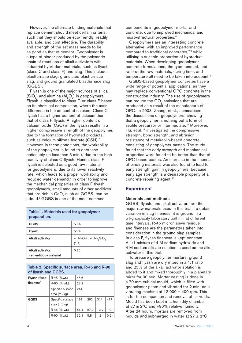
Materials and methodsGGBS, flyash, and alkali activators are the major raw materials used in this trial. To obtain variation in slag fineness, it is ground in a 5 kg capacity laboratory ball mill at different time intervals. R-45 micron sieve residue and fineness are the parameters taken into consideration in the ground slag samples. In class F, flyash fineness is kept constant. A 1:1 mixture of 4 M sodium hydroxide and 4 M sodium silicate solution is used as the alkali activator in this trial.
To prepare geopolymer mortars, ground slag and flyash are dry mixed in a 1:1 ratio and 25% of the alkali activator solution is added to it and mixed thoroughly in a planetary mixer for 90 sec. Mortar casting is done in a 70 mm cubical mould, which is filled with geopolymer paste and vibrated for 2 min. on a vibrating machine at 12 000 ± 400 rpm. This is for the compaction and removal of air voids. Mould has been kept in a humidity chamber at 27 ± 2°C and +90% relative humidity. After 24 hours, mortars are removed from moulds and submerged in water at 27 ± 2°C
Table 2. Specifi c surface area, R-45 and R-90 of fl yash and GGBS.Flyash (fi xed
fi neness)
R-45 (%wt.) 45.6
R-90 (% wt.) 23.2
Specifi c surface
area (m2/kg)
214
GGBS Specifi c surface
area (m2/kg)
184 262 314 417
R-45 (% wt.) 56.4 27.9 13.2 1.9
R-90 (%wt.) 32.1 5.8 1.8 0.2
Table 1. Materials used for geopolymer preparation.
GGBS 50%
Flyash 50%
Alkali activator 4mNaOH : 4mNa2SiO
3
(1:1)
Alkali activator:
cementitious material
0.25
Order our catalogue online
For over 90 years, KettenWulf, as an expanding global company, has stood for quality, reliability and flexibility. More than 1400 employees develop, manufacture and market customized solutions in the field of conveying and drive technology at ten locations across Europe, America, Australia and Asia. All around the globe, KettenWulf is your strategic partner when it comes to delivering cutting edge product quality.
NEW HIGH SPEED CONVEYING
Sprockets for bucket elevator
k fCentral bucket elevator chain with forged link plates
ENERGY EFFICIENCY
MAXIMUM LOAD
LOW MAINTENANCE
FATIGUE STRENGTH
KettenWulf Betriebs GmbHZum Hohenstein 1559889 Eslohe-KückelheimGermany
T + 49.(0)2973.801-0F + 49.(0)2973.801-228
Chains & Sprockets made by KettenWulf
Experts for the bulk materialhandling industry
08.-14.04.Visit us:Hall B2,booth 200
munich
01.-05.04.Visit us:Hall 25, booth D25
30 World Cement March 2019
for a compressive strength test at intervals of one day, three days, seven days, and 28 days.
CharacterisationThe structural analysis of the geopolymer was characterised by the x-ray defraction technique, using a x-ray diffractometer (Bruker, D8 Endeavor) with Cu-Kα radiation (λ = 1.54 Ǻ) over a wide range of Bragg’s angles (8° ≤ 2θ ≤ 70°). The elemental analysis was done by a x-ray fl orescence analyser (PANalytical,
Axiox mAX) and the morphology of the geopolymer was studied by optical microscope (ZEISS Axio Scope A1) with a magnifi cation of 500X. The compressive strength was measured on different samples at one day, three days, seven days, and 28 days using a compressive strength testing machine with a maximum load of 500 kN and a loading force of 2.8 kN/sec.
Results and discussion
X-ray fluorescence studyThe elemental analysis of the GGBS and flyash was carried out to find the percentage of elements (in the form of oxides) present in the respective materials and the results are shown in Table 3.
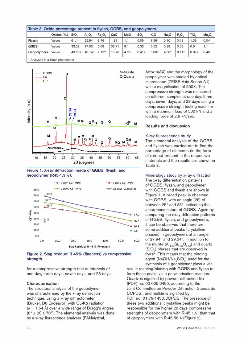
Mineralogy study by x-ray diffraction The x-ray differentiation patterns of GGBS, fl yash, and geopolymer with GGBS and fl yash are shown in Figure 1. A broad peak is observed with GGBS, with an angle (2θ) of between 25° and 35°, indicating the amorphous nature of GGBS. Again by comparing the x-ray diffraction patterns of GGBS, fl yash, and geopolymers, it can be observed that there are some additional peaks (crystalline phases) in geopolymers at an angle of 27.94° and 29.34°, in addition to the mullite (Al
4.64Si
1.36O
9.68) and quartz
(SiO2) phases that are observed in
fl yash. This means that the binding agent (NaOH/Na
2SiO
3) used for the
synthesis of a geopolymer plays a vital role in reacting/binding with GGBS and fl yash to form these peaks via a polymerisation reaction. Quartz is signifi ed by powder diffraction fi le (PDF) no. 00-005-0490, according to the Joint Committee on Powder Diffraction Standards (JCPDS), and mullite is signifi ed by PDF no. 01-79-1453, JCPDS. The presence of these two additional crystalline peaks might be responsible for the higher 28 days compressive strengths of geopolymers with R-45 1.9, than that of geopolymers with R-45 56.4 (Figure 2).
Figure 1. X-ray diffraction image of GGBS, fl yash, and geopolymer (R45-1.9%).
9.6
24.8
16.9
49.7
26.2
57.7
37.2
69.2
0.0
10.0
20.0
30.0
40.0
50.0
60.0
70.0
80.0
0.0 10.0 20.0 30.0 40.0 50.0 60.0
CST-
MPa
Slag Residue: R-45 % (Fineness)
1 day CST(MPa) 3 days CST(MPa)
7 days CST(MPa) 28 days CST(MPa)
Figure 2. Slag residue: R-45% (fi neness) vs compressive strength.
Table 3. Oxide percentage present in fl yash, GGBS, and geopolymers.Oxides (%) SiO2 Al2O3 Fe2O3 CaO MgO SO3 K2O Na2O P2O5 TiO2 Mn2O3
Flyash Values 61.14 25.84 3.76 1.81 1.1 0.06 1.56 0.10 0.18 1.36 0.04
GGBS Values 33.28 17.03 0.68 36.71 9.1 0.33 0.52 0.38 0.02 0.6 1.1
Geopolymers Values 43.237 18.145 2.127 15.76 4.29 0.412 0.891 4.68* 0.11* 0.877 0.46
* Analysed in a fl ame photometer
MAXIMUM EXPERIENCE CONVEYING SOLUTIONS
Design & Manufacturing: • Belt Conveyors • Belt Elevators
Own engineering Projects development Preassembled delivery
Services: • Technical Assistance • Installation • Commissioning • Spare parts
Tel. +34 976 770 656 (Spain) • www.cintasa.com
32 World Cement March 2019
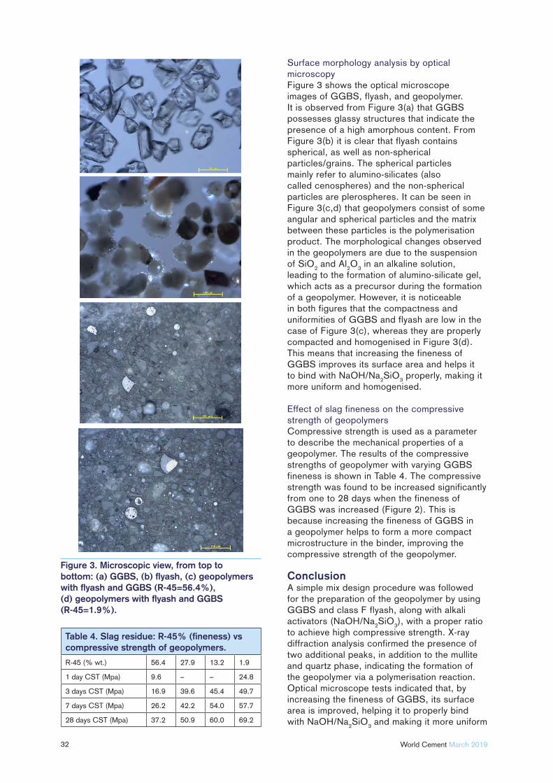
Surface morphology analysis by optical microscopyFigure 3 shows the optical microscope images of GGBS, flyash, and geopolymer. It is observed from Figure 3(a) that GGBS possesses glassy structures that indicate the presence of a high amorphous content. From Figure 3(b) it is clear that flyash contains spherical, as well as non-spherical particles/grains. The spherical particles mainly refer to alumino-silicates (also called cenospheres) and the non-spherical particles are plerospheres. It can be seen in Figure 3(c,d) that geopolymers consist of some angular and spherical particles and the matrix between these particles is the polymerisation product. The morphological changes observed in the geopolymers are due to the suspension of SiO
2 and Al
2O
3 in an alkaline solution,
leading to the formation of alumino-silicate gel, which acts as a precursor during the formation of a geopolymer. However, it is noticeable in both figures that the compactness and uniformities of GGBS and flyash are low in the case of Figure 3(c), whereas they are properly compacted and homogenised in Figure 3(d). This means that increasing the fineness of GGBS improves its surface area and helps it to bind with NaOH/Na
2SiO
3 properly, making it
more uniform and homogenised.
Effect of slag fineness on the compressive strength of geopolymersCompressive strength is used as a parameter to describe the mechanical properties of a geopolymer. The results of the compressive strengths of geopolymer with varying GGBS fineness is shown in Table 4. The compressive strength was found to be increased significantly from one to 28 days when the fineness of GGBS was increased (Figure 2). This is because increasing the fineness of GGBS in a geopolymer helps to form a more compact microstructure in the binder, improving the compressive strength of the geopolymer.
ConclusionA simple mix design procedure was followed for the preparation of the geopolymer by using GGBS and class F flyash, along with alkali activators (NaOH/Na
2SiO
3), with a proper ratio
to achieve high compressive strength. X-ray diffraction analysis confirmed the presence of two additional peaks, in addition to the mullite and quartz phase, indicating the formation of the geopolymer via a polymerisation reaction. Optical microscope tests indicated that, by increasing the fineness of GGBS, its surface area is improved, helping it to properly bind with NaOH/Na
2SiO
3 and making it more uniform
Table 4. Slag residue: R-45% (fi neness) vs compressive strength of geopolymers.
R-45 (% wt.) 56.4 27.9 13.2 1.9
1 day CST (Mpa) 9.6 – – 24.8
3 days CST (Mpa) 16.9 39.6 45.4 49.7
7 days CST (Mpa) 26.2 42.2 54.0 57.7
28 days CST (Mpa) 37.2 50.9 60.0 69.2
Figure 3. Microscopic view, from top to bottom: (a) GGBS, (b) fl yash, (c) geopolymers with fl yash and GGBS (R-45=56.4%), (d) geopolymers with fl yash and GGBS (R-45=1.9%).

34 World Cement March 2019
and homogenised. Increasing the fineness of GGBS enhances the rate of the polymerisation reaction and forms a high compressive strength geopolymer.
References1. LASKAR, S. M. and TALUKDAR, S.,
Construction and Building Materials, No. 154 (2017),
pp. 176 − 190.
2. PART, W. K., RAMLI, M., and CHEAH, C.B.,
Construction and Building Materials, No. 77 (2015),
pp. 370 − 395.
3. DIAZ, E.I., ALLOUCHE, E.N., and EKLUND, S.,
Fuel, No. 89 (2010), pp. 992 − 996.
4. RANGAN, B., Concrete in Australia, No. 34 (2010),
pp. 37 − 43.
5. KIM, M.S., JUN, Y., LEE, C., and OH, J. E.,
Cement and Concrete Research, No. 54 (2013),
pp. 208 − 214.
6. HAHA, M. B., SAOUT, G. L., WINNEFELD, F., and
LOTHENBACH, B., Cement and Concrete Research,No. 41 (2011), pp. 301 − 310.
7. VAN JAARSVELD, J. G. S., VAN DEVENTER, J. S. J.,
and LUKEY, G. C., Chemical Engineering Journal,No. 89 (2002), pp. 63 − 73.
8. HARDJITO, D., WALLAH, S. E., SUMAJOUW, D. M.,
and RANGAN, B.V., ACI Materials Journal, No. 101
(2004) pp. 467 − 472.
9. PART, W. K., RAMLI, M., and CHEAH, C. B.,
Construction and Building Materials, No. 77 (2015),
pp. 370 − 395.
10. BABAJIDE, O., MUSYOKA, N., PETRIK, L., and
AMEER, F., Catalysts Today, No. 190 (2012),
pp. 54 − 60.
11. HU, S., WANG, H., ZHANG, G., and DING, Q.,
Cement and Concrete Composites, No. 30 (2008) pp.
239 − 244.
12. KIM, J. H. and LEE, H. S., Materials, No. 10 (2017),
pp. 1050.
About the authorsP. Ponnusamy has a post graduate degree in Chemistry and is Manager of Quality Management and R&D at Dalmia Bharat Cement, with 19 years of experience in the cement industry.
Praseeja Shankaran is currently working in the R&D Centre of Dalmia Bharat Cement and has eight years of experience in the microscopy and morphology of materials used in the cement industry.
Dr Mukesh kumar Mishra is Assistant Manager of Quality Management and R&D at Dalmia Bharat Cement, and has one year of experience in the cement industry.
Dr S. P. Pandey is Deputy Executive Director of Quality Management and R&D at Dalmia Bharat Cement, with over 28 years of extensive experience in the cement industry.
CONVEYOR BELTS
ITALIAN
TECHNOLOGY
T +49 2961 7405-0
Your Specialist for
EXPLOSION SAFETYand
PRESSURE RELIEFSOLUTIONS
Gallbergweg 21 | 59929 Brilon, Germany
F +49 2961 50714 | www.rembe.de
MadeinGermany
© R
EM
BE
® |
All
rig
hts
re
serv
ed
Consulting. Engineering. Products. Service.

35
Matteo Magistri, Mapei SpA, overviews calorimetry and its applications to cements and concrete.
Modern cement production and use represent highly specialised areas of investigation. Quality, performance, and durability optimisation involve a deep knowledge of chemistry and mineralogy,
as well as the use of advanced analytical techniques. Among these, calorimetry has received a lot of attention,
due to its potential for offering a detailed understanding of the hydration process. Recent advances in calorimetry technology and design have improved the sensitivity of the method and, consequently, the level of information that can be obtained. The purpose of this article is to give a general overview of the applications of calorimetric methods and the theory behind it.
General calorimetry methodsCalorimetry (from Latin and Greek words) means ‘measure of heat’. Generally speaking, it studies the amount of heat released and absorbed by physical systems. Heat is associated with chemical or physical modifi cations in
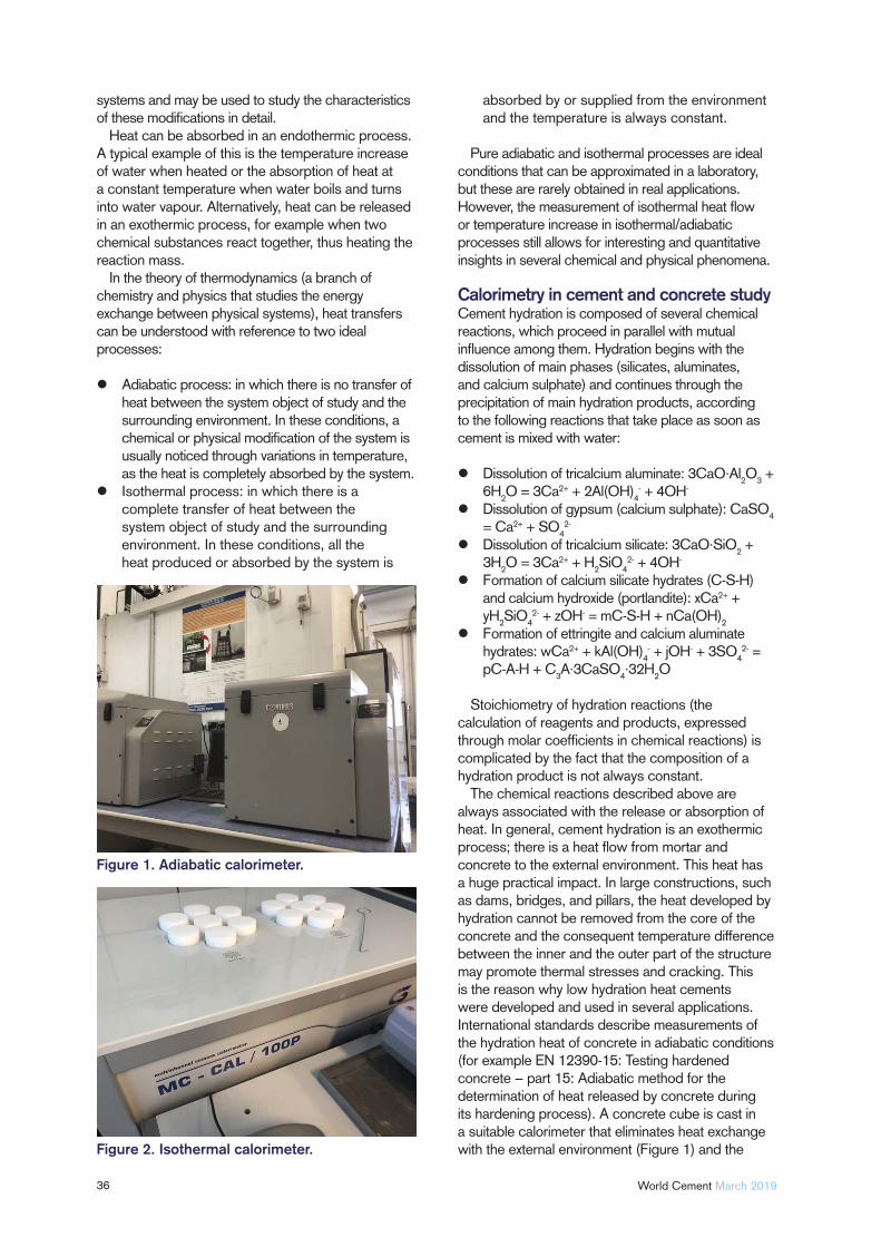
36 World Cement March 2019
systems and may be used to study the characteristics of these modifi cations in detail.
Heat can be absorbed in an endothermic process. A typical example of this is the temperature increase of water when heated or the absorption of heat at a constant temperature when water boils and turns into water vapour. Alternatively, heat can be released in an exothermic process, for example when two chemical substances react together, thus heating the reaction mass.
In the theory of thermodynamics (a branch of chemistry and physics that studies the energy exchange between physical systems), heat transfers can be understood with reference to two ideal processes:
Adiabatic process: in which there is no transfer of heat between the system object of study and the surrounding environment. In these conditions, a chemical or physical modifi cation of the system is usually noticed through variations in temperature, as the heat is completely absorbed by the system.
Isothermal process: in which there is a complete transfer of heat between the system object of study and the surrounding environment. In these conditions, all the heat produced or absorbed by the system is
absorbed by or supplied from the environment and the temperature is always constant.
Pure adiabatic and isothermal processes are ideal conditions that can be approximated in a laboratory, but these are rarely obtained in real applications. However, the measurement of isothermal heat fl ow or temperature increase in isothermal/adiabatic processes still allows for interesting and quantitative insights in several chemical and physical phenomena.
Calorimetry in cement and concrete studyCement hydration is composed of several chemical reactions, which proceed in parallel with mutual infl uence among them. Hydration begins with the dissolution of main phases (silicates, aluminates, and calcium sulphate) and continues through the precipitation of main hydration products, according to the following reactions that take place as soon as cement is mixed with water:
Dissolution of tricalcium aluminate: 3CaO·Al2O
3 +
6H2O = 3Ca2+ + 2Al(OH)
4- + 4OH-
Dissolution of gypsum (calcium sulphate): CaSO4
= Ca2+ + SO42-
Dissolution of tricalcium silicate: 3CaO·SiO2 +
3H2O = 3Ca2+ + H
2SiO
42- + 4OH-
Formation of calcium silicate hydrates (C-S-H) and calcium hydroxide (portlandite): xCa2+ + yH
2SiO
42- + zOH- = mC-S-H + nCa(OH)
2
Formation of ettringite and calcium aluminate hydrates: wCa2+ + kAl(OH)
4- + jOH- + 3SO
42- =
pC-A-H + C3A·3CaSO
4·32H
2O
Stoichiometry of hydration reactions (the calculation of reagents and products, expressed through molar coeffi cients in chemical reactions) is complicated by the fact that the composition of a hydration product is not always constant.
The chemical reactions described above are always associated with the release or absorption of heat. In general, cement hydration is an exothermic process; there is a heat fl ow from mortar and concrete to the external environment. This heat has a huge practical impact. In large constructions, such as dams, bridges, and pillars, the heat developed by hydration cannot be removed from the core of the concrete and the consequent temperature difference between the inner and the outer part of the structure may promote thermal stresses and cracking. This is the reason why low hydration heat cements were developed and used in several applications. International standards describe measurements of the hydration heat of concrete in adiabatic conditions (for example EN 12390-15: Testing hardened concrete − part 15: Adiabatic method for the determination of heat released by concrete during its hardening process). A concrete cube is cast in a suitable calorimeter that eliminates heat exchange with the external environment (Figure 1) and the
Figure 1. Adiabatic calorimeter.
Figure 2. Isothermal calorimeter.

The Netherlands | +31 15 369 54 44 | [email protected] | www.mullerbeltex.com
Solid partners for powder and bulk handling components
YOUR SERVICE & KNOWLEDGE SUPPLIER OF RELIABLE COMPONENTS FOR BELT BUCKET ELEVATORS
POLYSUR® FERRO STEEL CORD BELT
FOR BUCKET ELEVATORS
Specially designed for heavy duty and high heat industrial applications with
long centre distances. Assuring optimum performance
and maximum service life.
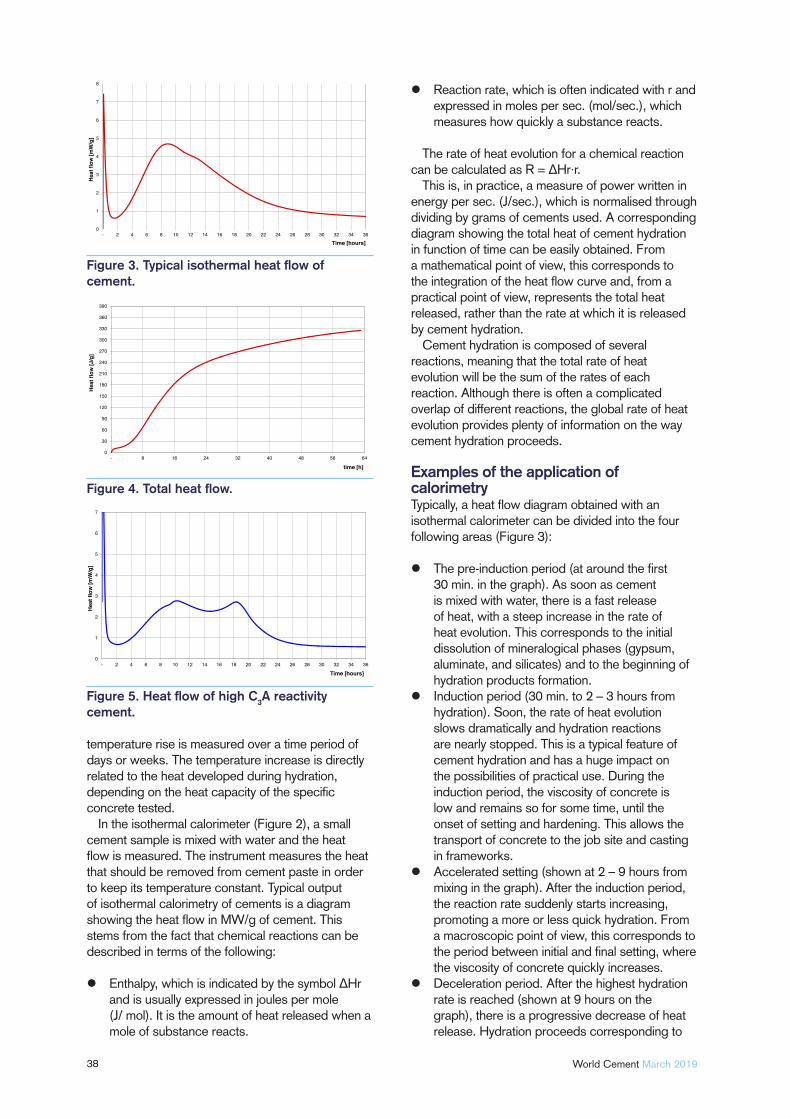
38 World Cement March 2019
temperature rise is measured over a time period of days or weeks. The temperature increase is directly related to the heat developed during hydration, depending on the heat capacity of the specifi c concrete tested.
In the isothermal calorimeter (Figure 2), a small cement sample is mixed with water and the heat fl ow is measured. The instrument measures the heat that should be removed from cement paste in order to keep its temperature constant. Typical output of isothermal calorimetry of cements is a diagram showing the heat fl ow in MW/g of cement. This stems from the fact that chemical reactions can be described in terms of the following:
Enthalpy, which is indicated by the symbol ΔHr and is usually expressed in joules per mole (J/ mol). It is the amount of heat released when a mole of substance reacts.
Reaction rate, which is often indicated with r and expressed in moles per sec. (mol/sec.), which measures how quickly a substance reacts.
The rate of heat evolution for a chemical reaction can be calculated as R = ΔHr·r.
This is, in practice, a measure of power written in energy per sec. (J/sec.), which is normalised through dividing by grams of cements used. A corresponding diagram showing the total heat of cement hydration in function of time can be easily obtained. From a mathematical point of view, this corresponds to the integration of the heat fl ow curve and, from a practical point of view, represents the total heat released, rather than the rate at which it is released by cement hydration.
Cement hydration is composed of several reactions, meaning that the total rate of heat evolution will be the sum of the rates of each reaction. Although there is often a complicated overlap of different reactions, the global rate of heat evolution provides plenty of information on the way cement hydration proceeds.
Examples of the application of calorimetryTypically, a heat fl ow diagram obtained with an isothermal calorimeter can be divided into the four following areas (Figure 3):
The pre-induction period (at around the fi rst 30 min. in the graph). As soon as cement is mixed with water, there is a fast release of heat, with a steep increase in the rate of heat evolution. This corresponds to the initial dissolution of mineralogical phases (gypsum, aluminate, and silicates) and to the beginning of hydration products formation.
Induction period (30 min. to 2 – 3 hours from hydration). Soon, the rate of heat evolution slows dramatically and hydration reactions are nearly stopped. This is a typical feature of cement hydration and has a huge impact on the possibilities of practical use. During the induction period, the viscosity of concrete is low and remains so for some time, until the onset of setting and hardening. This allows the transport of concrete to the job site and casting in frameworks.
Accelerated setting (shown at 2 – 9 hours from mixing in the graph). After the induction period, the reaction rate suddenly starts increasing, promoting a more or less quick hydration. From a macroscopic point of view, this corresponds to the period between initial and fi nal setting, where the viscosity of concrete quickly increases.
Deceleration period. After the highest hydration rate is reached (shown at 9 hours on the graph), there is a progressive decrease of heat release. Hydration proceeds corresponding to
0
1
2
3
4
5
6
7
8
- 2 4 6 8 10 12 14 16 18 20 22 24 26 28 30 32 34 36
Heat
flow
[mW
/g]
Time [hours]
0
30
60
90
120
150
180
210
240
270
300
330
360
390
- 8 16 24 32 40 48 56 64
Heat
flow
[J/g
]
time [h]
0
1
2
3
4
5
6
7
- 2 4 6 8 10 12 14 16 18 20 22 24 26 28 30 32 34 36
Hea
t flo
w [m
W/g
]
Time [hours]
Figure 3. Typical isothermal heat fl ow of cement.
Figure 4. Total heat fl ow.
Figure 5. Heat fl ow of high C3A reactivity cement.
No Contact with the Belt
High Performance Detectors
Multi-Detectors Configuration
Easy Calibration
2 Years Warranty
GEOSCAN –C Advantages GEOSCAN –C Advantages
Contact us for advice and assistance: Tel: +61 7 3710 8400 Fax: +61 7 3710 8499 Web site: www.scantech.com.au Email: [email protected]
On-line Real Time Analysis for the Cement Industry
-C
ON-BELT ELEMENTAL ANALYSER AND BLENDING SOFTWARE FOR CEMENT
BLENDSCAN Advantages
Minimises variations in product quality
Increased production Increased profits Configuration flexibility Reliable HMI based on Siemens
WinCC
40 World Cement March 2019
the development of mechanical performances, which are usually measured as compressive strengths. However, this occurs at a slower rate. The area where reaction rate increases again is called a ‘shoulder’ and is often seen here. It is related to some chemical reactions during hydration.
The reasons behind the induction period and subsequent setting and hardening are widely discussed in several scientifi c works.1 Further papers describe in detail the common interpretation of the correspondence between several areas in the heat fl ow diagram and the group of related chemical reactions.2
An initial peak is related to dissolution reactions and the formation of the fi rst hydration products. The main hydration peak corresponds to the fast growth of hydration products, where the shoulder during deceleration periods is related to a further reaction of aluminates. This takes place after the consumption of gypsum that has been completely converted to hydration products.
The corresponding total heat fl ow of the same cement is shown in Figure 4.
Interpretation of cement reactivityIsothermal calorimetry represents a fi ngerprint of cement reactivity. In Figure 5, the heat fl ow of a different type of cement is represented. By comparing this to the cement described in Figure 3, it appears that reactivity, in particular that of aluminates, is completely different. There is often higher heat release during early hydration and after a main peak. This is an indication of highly reactive C
3A.
Cement additives optimisationChemical additives, such as grinding aids and performance enhancers, are widely used in modern cements, with the purpose of optimising cement performance and composition, as well as reducing production costs. Modern cement additives are formulated with a wide range of chemical substances, which allow the fi ne tuning of cement properties through suitable tailor-made formulations.
Additives can have a deep impact on cement hydration and isothermal calorimetry is a good way to understand their effect. Figure 6 represents the effect of different additives in mixing water in the same cement. There are strong variations of heat fl ow associated with all chemical reactions and it is possible to interpret for the effect of additives on the basis of the hydration reactions involved.
Correlation of compressive strengths with total heat fl owConsidering that heat fl ow is related to the number of moles reacted and the reaction heat, the total heat fl ow represents a measure of the degree of hydration
0
1
2
3
4
5
6
7
- 4 8 12 16 20 24 28 32 36
Hea
t flo
w [m
W/g
]
time [hours]
CEM - Blank
CEM w/additive 1
CEM w/additive 2
CEM w/additive 3
10
12
14
16
18
20
22
24
26
28
150 170 190 210 230 250 270
24 h
str
engt
hs (M
Pa)
Total heat (J/g)
CEM 1CEM 2
40
45
50
55
60
65
150 170 190 210 230 250 270
28 d
com
pres
sive
str
engt
hs (M
Pa)
Total heat (J/g)
CEM 1CEM 2
Figure 6. Effect of chemical additives.
Figure 7. 24 hour mortar strength vs total heat fl ow.
Figure 8. 28 day mortar strength vs total heat fl ow.
Figure 9. Adiabatic calorimetry results.
41March 2019 World Cement
of different types of cement. It is not surprising that this parameter is correlated to mechanical performances such as compressive strengths, for example measured in mortar. Figures 7 and 8 report the early and late strengths of cement in the function of total heat fl ow, measured with isothermal calorimetry. The correlation is almost linear, in particular at 24 hours, while at 28 days other parameters, such as microstructure, may reduce the linearity with total heat. Further details can be found in specialised articles.3
Adiabatic calorimetryIn adiabatic calorimetry there is no exchange of heat between concrete or mortar and the surrounding environment. The heat released by cement hydration is completely converted to the temperature increase of the mass. Although less accurate than isothermal calorimetry, the adiabatic method is closer to real applications, where heat exchange is limited by the low surface-to-mass ratio of concrete, as well as by its high thermal capacity and low heat conduction.
Figure 9 represents the temperature profi le of fl yash and pozzolan cement, measured with an adiabatic calorimeter. Flyash cement is more exothermic and its higher heat release increases its temperature in comparison to pozzolan cement. Temperature increase is thus related to the reactivity of cements, allowing the choice of the correct cement, if heat of hydration is a main requirement.
References1. SCRIVENER, K.L., JUILLAND, P., and MONTEIRO, P.,
‘Advances in Understanding Hydration of Portland
Cement’, Cement & Concrete Research, Vol. 78 (2015),
pp. 38 − 56.
2. JANSEN, D., GOETZ-NEUNHOEFFER, F.,
LOTHENBACH, B., and NEUBAUER, J., ‘The Early
Hydration of Ordinary Portland Cement (OPC): An
Approach Comparing Measured Heat Flow with Calculated
Heat Flow from QXRD’, Cement & Concrete Research, Vol. 42 (2012), pp.134 − 138.
3. WANG, H., QI, C., LOPEZ, W., and FARZAM, H.,
‘Use of Isothermal Conduction Calorimetric Method
for Measuring the Heat of Hydration of Cement’,
Journal of ASTM International, Vol. 6, No. 10 (2009).
About the authorMatteo Magistri graduated in industrial chemistry. He currently holds the position of R&D Group Manager for cement additives in Mapei SpA, a multinational company leader in chemical products for building. In charge of R&D and technical assistance in the fi eld of hydraulic binders, he is an expert in the formulation of chemical additives used for the improvement of the cement grinding process and as performance enhancers of portland cements. He is an inventor of a number patents and author of several papers.
Mined raw materials travel along extensive transport routes.
Overland and pipe conveyors are an energy effi cient, reliable and
environmentally friendly way of transporting the commodities
over long distances to the plant or storage area. We customise
the curved belt conveyors to overcome any challenging topo-
graphical circumstances. This minimises the transfer points
and the number of systems and reduces investment, operational
and maintenance costs.
For more information visit www.beumergroup.com
SOME THINK RAW MATERIAL TRANSPORT REQUIRES A COMPLEX INFRA-STRUCTURE. WE THINK DIFFERENT.
Visit us!
POWTECH, Nuremberg,
Germany
April 09 - 11, 2019
Hall 1, stand 1-627
Visit us!
bauma, Munich, Germany
April 08 – 14, 2019
Hall B2, stand 413

42

43
Opportunity
NOXHelmut Hoppe, VDZ, gives an overview
of the development of NOX reduction
technologies.
For every cement producer, NO
X abatement is a long-term
environmental issue. More than 30 years ago, fi rst tests with the selective non-catalytic reduction (SNCR) process were carried out, and almost 20 years ago selective
catalytic reduction (SCR) technology was introduced for the fi rst time in the cement industry. In the following years, extensive demonstration projects were undertaken to further develop this abatement technology. Today, cement plants have to meet ambitious emission limit values, which have already resulted in the installation of the fi rst multi-component abatement technologies.
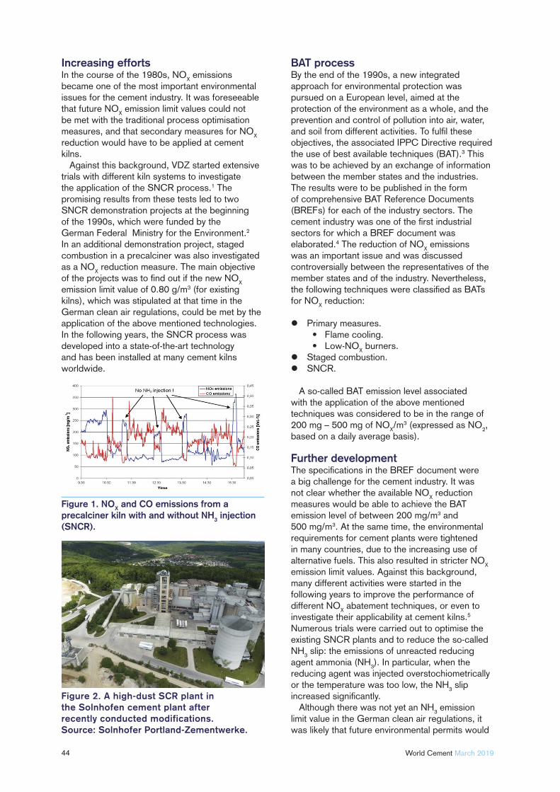
44 World Cement March 2019
Increasing efforts In the course of the 1980s, NO
X emissions
became one of the most important environmental issues for the cement industry. It was foreseeable that future NO
X emission limit values could not
be met with the traditional process optimisation measures, and that secondary measures for NO
X
reduction would have to be applied at cement kilns.
Against this background, VDZ started extensive trials with different kiln systems to investigate the application of the SNCR process.1 The promising results from these tests led to two SNCR demonstration projects at the beginning of the 1990s, which were funded by the German Federal Ministry for the Environment.2 In an additional demonstration project, staged combustion in a precalciner was also investigated as a NO
X reduction measure. The main objective
of the projects was to fi nd out if the new NOX
emission limit value of 0.80 g/m3 (for existing kilns), which was stipulated at that time in the German clean air regulations, could be met by the application of the above mentioned technologies. In the following years, the SNCR process was developed into a state-of-the-art technology and has been installed at many cement kilns worldwide.
BAT processBy the end of the 1990s, a new integrated approach for environmental protection was pursued on a European level, aimed at the protection of the environment as a whole, and the prevention and control of pollution into air, water, and soil from different activities. To fulfi l these objectives, the associated IPPC Directive required the use of best available techniques (BAT).3 This was to be achieved by an exchange of information between the member states and the industries. The results were to be published in the form of comprehensive BAT Reference Documents (BREFs) for each of the industry sectors. The cement industry was one of the fi rst industrial sectors for which a BREF document was elaborated.4 The reduction of NO
X emissions
was an important issue and was discussed controversially between the representatives of the member states and of the industry. Nevertheless, the following techniques were classifi ed as BATs for NO
X reduction:
Primary measures.• Flame cooling.• Low-NO
X burners.
Staged combustion.SNCR.
A so-called BAT emission level associated with the application of the above mentioned techniques was considered to be in the range of 200 mg – 500 mg of NO
X/m3 (expressed as NO
2,
based on a daily average basis).
Further development The specifi cations in the BREF document were a big challenge for the cement industry. It was not clear whether the available NO
X reduction
measures would be able to achieve the BAT emission level of between 200 mg/m3 and 500 mg/m3. At the same time, the environmental requirements for cement plants were tightened in many countries, due to the increasing use of alternative fuels. This also resulted in stricter NO
X
emission limit values. Against this background, many different activities were started in the following years to improve the performance of different NO
X abatement techniques, or even to
investigate their applicability at cement kilns.5
Numerous trials were carried out to optimise the existing SNCR plants and to reduce the so-called NH
3 slip: the emissions of unreacted reducing
agent ammonia (NH3). In particular, when the
reducing agent was injected overstochiometrically or the temperature was too low, the NH
3 slip
increased signifi cantly.Although there was not yet an NH
3 emission
limit value in the German clean air regulations, it was likely that future environmental permits would
Figure 1. NOX and CO emissions from a precalciner kiln with and without NH3 injection (SNCR).
Figure 2. A high-dust SCR plant in the Solnhofen cement plant after recently conducted modifications.Source: Solnhofer Portland-Zementwerke.
March 2019 World Cement
also include an emission limit value for NH3. In
this connection, the so-called high-effi ciency SNCR process was developed, which aims at an optimised injection of the reducing agent.6,7 To achieve this, most technology providers use different injection lances in different layers, with single lance control and online monitoring systems of gas temperatures and gas distribution to follow all process fl uctuations.
Furthermore, the application of the SNCR process at precalciner kilns was not investigated suffi ciently at this time. However, operational trials in the following years showed that precalciners offer good conditions for the SNCR process, as there is a suffi cient residence time for the reduction reactions in the appropriate temperature window. As a result, high NO
X reduction rates
could be achieved, accompanied only by very low NH
3 emissions (Figure 1).
In addition, the SCR process, which was state-of-the-art in the power sector and for municipal incinerators, had only been tested at cement kilns in small-scale pilot trials.8,9 As a result, the SCR process was not yet considered as BAT in the fi rst BREF document, but apart from this there were opinions attributing an associated emission level of between 100 mg and 200 mg of NO
X/m3 to this technique. As there was an obvious
need for full-scale trials, the fi rst SCR plant (high-dust version, see Figure 2) was erected and tested in a cement plant in southern Germany.10 Soon after this, another SCR plant was installed in the Monselice plant in Italy.11
Later, two demonstration projects (one high dust SCR, one tail-end SCR), with funding from the KfW Development Bank, were undertaken in German cement plants. Both projects were accompanied by extensive measuring programmes that were carried out by VDZ (Figure 3).
The results showed that NOX emission levels
below 200 mg/m3 with very low NH3 slip could
be achieved. Furthermore, it was also shown that organic compounds could be reduced. After the successful optimisation of dust cleaning (high dust SCR), the duration of the catalyst layers seemed to be satisfactory, meaning that the operational costs could be kept at a reasonable level. The results have been summarised in extensive reports.12,13
Revisions and legislative requirementsBAT is a dynamic concept, as emission abatement technologies are continually developing and new technologies might also be introduced in different industrial sectors. Therefore, a review of the cement BREF was started in 2009, resulting in an updated document with modifi ed specifi cations regarding NO
X reduction.14 In this version, the
SCR process was also classifi ed as BAT, but was subject to “appropriate catalyst and process
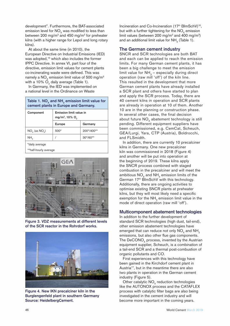
46 World Cement March 2019
development”. Furthermore, the BAT-associated emission level for NO
X was modifi ed to less than
between 200 mg/m3 and 450 mg/m3 for preheater kilns (with a higher range for Lepol and long rotary kilns).
At about the same time (in 2010), the European Directive on Industrial Emissions (IED)was adopted,15 which also includes the former IPPC Directive. In annex VI, part four of the directive, emission limit values for cement plants co-incinerating waste were defi ned. This was namely a NO
X emission limit value of 500 mg/m3
with a 10% O2 daily average (Table 1).
In Germany, the IED was implemented on a national level in the Ordinance on Waste
Incineration and Co-Incineration (17th BImSchV)16, but with a further tightening for the NO
X emission
limit values (between 200 mg/m3 and 400 mg/m3) and an additional limit value for NH
3 (Table 1).
The German cement industrySNCR and SCR technologies are both BAT and each can be applied to reach the emission limits. For many German cement plants, it has been a big challenge to meet the emission limit value for NH
3 – especially during direct
operation (raw mill ‘off’) of the kiln line. This resulted in the development that more German cement plants have already installed a SCR plant and others have started to plan and apply the SCR process. Today, there are 40 cement kilns in operation and SCR plants are already in operation at 10 of them. Another 10 are in the planning or construction phase. In several other cases, the final decision about future NO
X abatement technology is still
pending. Different equipment suppliers have been commissioned, e.g. CemCat, Scheuch, GEA/Lurgi, Yara, CTP (Austria), Boldrocchi, and FLSmidth.
In addition, there are currently 10 precalciner kilns in Germany. One new precalciner kiln was commissioned in 2018 (Figure 4) and another will be put into operation at the beginning of 2019. These kilns apply the SNCR process combined with staged combustion in the precalciner and will meet the ambitious NO
X and NH
3 emission limits of the
German 17th BImSchV with this technology. Additionally, there are ongoing activities to optimise existing SNCR plants at preheater kilns, but they will most likely need a specifi c exemption for the NH
3 emission limit value in the
mode of direct operation (raw mill ‘off’).
Multicomponent abatement technologiesIn addition to the further development of standard SCR technologies (high dust, tail-end), other emission abatement technologies have emerged that can reduce not only NO
X and NH
3
emissions, but also other fl ue gas components. The DeCONO
X process, invented by the Austrian
equipment supplier, Scheuch, is a combination of a tail-end SCR and a thermal post-combustion of organic pollutants and CO.
First experiences with this technology have been gained in the Kirchdorf cement plant in Austria17, but in the meantime there are also two plants in operation in the German cement industry (Figure 5).
Other catalytic NOX reduction technologies
like the AUTONOX process and the CATAFLEX process with catalytic fi lter bags are also being investigated in the cement industry and will become more important in the coming years.
Figure 3. VDZ measurements at different levels of the SCR reactor in the Rohrdorf works.
Figure 4. New IKN precalciner kiln in the Burglengenfeld plant in southern Germany Source: HeidelbergCement.
Table 1. NOX and NH3 emission limit value for cement plants in Europe and Germany.
Component Emission limit value in
mg/m3, 10% O2
Europe Germany
NOX (as NO
2) 500* 200*/400**
NH3
/ 30*/60**
*daily average
**half-hourly average
Expect quality. Expect experience. Expect solutions.
We know flue gas treatment.
We offer customized flue gas treatment solutions and have
X to an impressive 180 mg/Nm3.
X X
Flue gas conditioningFans
Heat exchangers
We do it all.
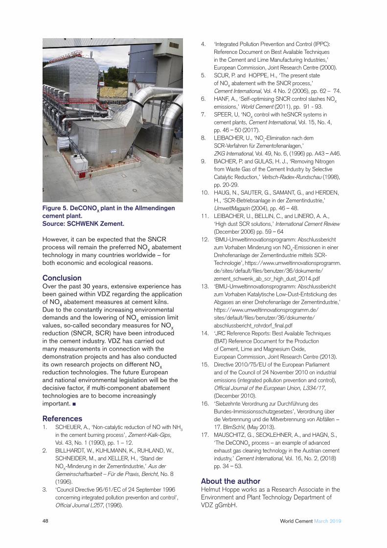
48 World Cement March 2019
However, it can be expected that the SNCR process will remain the preferred NO
X abatement
technology in many countries worldwide – for both economic and ecological reasons.
ConclusionOver the past 30 years, extensive experience has been gained within VDZ regarding the application of NO
X abatement measures at cement kilns.
Due to the constantly increasing environmental demands and the lowering of NO
X emission limit
values, so-called secondary measures for NOX
reduction (SNCR, SCR) have been introduced in the cement industry. VDZ has carried out many measurements in connection with the demonstration projects and has also conducted its own research projects on different NO
X
reduction technologies. The future European and national environmental legislation will be the decisive factor, if multi-component abatement technologies are to become increasingly important.
References1. SCHEUER, A., ‘Non-catalytic reduction of NO with NH
3
in the cement burning process’, Zement-Kalk-Gips, Vol. 43, No. 1 (1990), pp. 1 – 12.
2. BILLHARDT, W., KUHLMANN, K., RUHLAND, W.,
SCHNEIDER, M., and XELLER, H., ‘Stand der
NOX-Minderung in der Zementindustrie,’ Aus der
Gemeinschaftsarbeit – Für die Praxis, Bericht, No. 8
(1996).
3. ‘Council Directive 96/61/EC of 24 September 1996
concerning integrated pollution prevention and control’,
Official Journal L257, (1996).
4. ‘Integrated Pollution Prevention and Control (IPPC):
Reference Document on Best Available Techniques
in the Cement and Lime Manufacturing Industries,’
European Commission, Joint Research Centre (2000).
5. SCUR, P. and HOPPE, H., ‘The present state
of NOX abatement with the SNCR process,’
Cement International, Vol. 4 No. 2 (2006), pp. 62 – 74.
6. HANF, A., ‘Self-optimising SNCR control slashes NOX
emissions,’ World Cement (2011), pp. 91 - 93.
7. SPEER, U, ‘NOX control with heSNCR systems in
cement plants, Cement International, Vol. 15, No. 4,
pp. 46 50 (2017).
8. LEIBACHER, U., ‘NOx-Elimination nach dem
SCR-Verfahren für Zementofenanlagen,’
ZKG International, Vol. 49, No. 6, (1996) pp. A43 A46.
9. BACHER, P. and GULAS, H. J., ‘Removing Nitrogen
from Waste Gas of the Cement Industry by Selective
Catalytic Reduction,’ Veitsch-Radex-Rundschau (1998),
pp. 20-29.
10. HAUG, N., SAUTER, G., SAMANT, G., and HERDEN,
H., ‘SCR-Betriebsanlage in der Zementindustrie,’
UmweltMagazin (2004), pp. 46 48.
11. LEIBACHER, U., BELLIN, C., and LINERO, A. A.,
‘High dust SCR solutions,’ International Cement Review
(December 2006) pp. 59 64
12. ‘BMU-Umweltinnovationsprogramm: Abschlussbericht
zum Vorhaben Minderung von NOX-Emissionen in einer
Drehofenanlage der Zementindustrie mittels SCR-
Technologie’, https://www.umweltinnovationsprogramm.
de/sites/default/fi les/benutzer/36/dokumente/
zement_schwenk_ab_scr_high_dust_2014.pdf
13. ‘BMU-Umweltinnovationsprogramm: Abschlussbericht
zum Vorhaben Katalytische Low-Dust-Entstickung des
Abgases an einer Drehofenanlage der Zementindustrie,’
https://www.umweltinnovationsprogramm.de/
sites/default/fi les/benutzer/36/dokumente/
abschlussbericht_rohrdorf_fi nal.pdf
14. ‘JRC Reference Reports: Best Available Techniques
(BAT) Reference Document for the Production
of Cement, Lime and Magnesium Oxide,
European Commission, Joint Research Centre (2013).
15. Directive 2010/75/EU of the European Parliament
and of the Council of 24 November 2010 on industrial
emissions (integrated pollution prevention and control), Official Journal of the European Union, L334/17,
(December 2010).
16. ‘Siebzehnte Verordnung zur Durchführung des
Bundes-Immissionsschutzgesetzes’, Verordnung über
die Verbrennung und die Mitverbrennung von Abfällen −
17. BImSchV, (May 2013).
17. MAUSCHITZ, G., SECKLEHNER, A., and HAGN, S.,
‘The DeCONOX process – an example of advanced
exhaust gas cleaning technology in the Austrian cement
industry,’ Cement International, Vol. 16, No. 2, (2018)
pp. 34 53.
About the authorHelmut Hoppe works as a Research Associate in the Environment and Plant Technology Department of VDZ gGmbH.
Figure 5. DeCONOX plant in the Allmendingen cement plant.Source: SCHWENK Zement.

Global PublicationGlobal PublicationWorld Cement Webinar
What Value Can Digital Transformation Bring to
Mining companies? 20 March 2019
Register here: http://bit.ly/WCTOSIsoft2

Optimising Optimising Dry Dry
Sorbent Sorbent InjectionInjection
Optimising Dry
Sorbent Injection
50

51
Dr Ian Saratovsky, Gerald Hunt, and Martin Dillon, Lhoist, discuss sorbent application methods and system optimisation with regard to
acid gas and mercury compliance costs.
Portland cement (PC) production processes often result in emissions of gaseous pollutants, including sulfur dioxide (SO
2),
hydrochloric acid (HCl), and mercury (Hg), which are released from the heating of raw materials, as well as the fi ring of solid fuels inside the kiln. Throughout the US and the world, PC production facilities are required to control their acid gas and Hg emissions, according to limits dictated in their operating permits, consent decrees, and/or other regulatory mandates. In the US, the Clean Air Act has previously driven acid gas emission control requirements; however, other regulations and limits have recently been passed, such as the National Ambient Air Quality Standards, which drives increasingly stringent limits on SO
2 emissions. Specifi c to PC manufacture
in the US, the National Emission Standards for Hazardous Air Pollutants provides numerical limits for the emissions of particulate matter, hydrocarbons, dioxins/furans, Hg, and HCl. Dry sorbent injection (DSI) offers a cost-effective solution to comply with these regulatory requirements. During the DSI system design phase, careful attention must be paid to sorbent selection, sorbent application location, and sorbent distribution into the gas stream, to maximise DSI system performance. In this article, various critical aspects of system optimisation will be discussed, for the achievement of the lowest overall cost of compliance.
Background
System CAPEXDSI and activated carbon injection (ACI) are two mature and low capital technologies for acid gas control and vapour-phase Hg reduction, respectively. Both Hg and acid gas control sorbents have proven effective in a variety of industrial plants (i.e. utility, biomass, cement, waste incinerators, etc.). They have been used commercially in Europe and the US for over 20 years. Trial results from the previous HCl test campaign with CEMEX and Lhoist North America were detailed in a previous World Cement article.1
DSI and ACI systems usually consist of storage (either silo storage or bulk bag, i.e. ‘super sack’), after which the product is metered into an air stream and conveyed via dilute-phase into the process gas stream, upstream of a particulate collection device. However, while often considered a low capital solution relative to other acid gas scrubbing technologies, the greatest capital associated with DSI and ACI is the initial equipment procurement and installation. For applications where Hg control is either intermittent or low injection rates are needed, a blended hydrated lime (HL) and powdered activated carbon (PAC) sorbent allows for a single feed system to be used. For example, Lhoist North America’s
blended HL-PAC product enables concurrent acid gas and Hg control, using a single sorbent injection system (instead of installing and maintaining two nearly identical systems), to inject the sorbents simultaneously as a pre-blended, homogeneous product. Lhoist North America produces customised enhanced hydrated lime blends (branded Sorbacal®
SP and SPS) with brominated PAC. These are produced either in bag or bulk, in 5% PAC (weight by weight) blend increments up to 30%.
Optimising OPEXWhile a single, blended sorbent for Hg and acid gas can decrease overall system CAPEX by reducing the need to a single system, careful attention should be paid to optimising the quantity of sorbent required to achieve compliance. DSI system design guidelines are discussed in detail elsewhere.2,3 The focus of this article is to provide sorbent selection and sorbent application guidelines to achieve the most operationally cost-effective DSI programme. To this end, before equipment design and selection phases (or after system commissioning, if this was overlooked during design), plants should consider the following:
Optimal injection location (which depends on target pollutants). Sorbent type. Sorbent application/distribution within the gas stream.
Sorbent trials with temporary DSI systems are highly recommended before the system design and selection phases. Alternatively, it is possible to evaluate alternative injection locations after a DSI system has been installed. Sorbent trials should include the measurement of dose-response curves (i.e. parametric) at several different locations within the plant, to identify the most effi cient injection strategy.
DSI programme design considerations to minimise operating costs
Sorbent type: standard hydrated lime? Enhanced hydrated lime? Hydrated lime blended with PAC for simultaneous acid gas and Hg abatement?Injection location: sorbent injection at kiln inlet? Gas conditioning tower (GCT) inlet? GCT outlet? Baghouse (BH) inlet? Induced draft fan inlet? The abatement of HCl and SO
2 often requires
different injection locations. Injection lance type and confi guration: standard pipe lances? Advanced sorbent distribution technologies? Static mixing lance designs? Dynamic mixing lance designs?
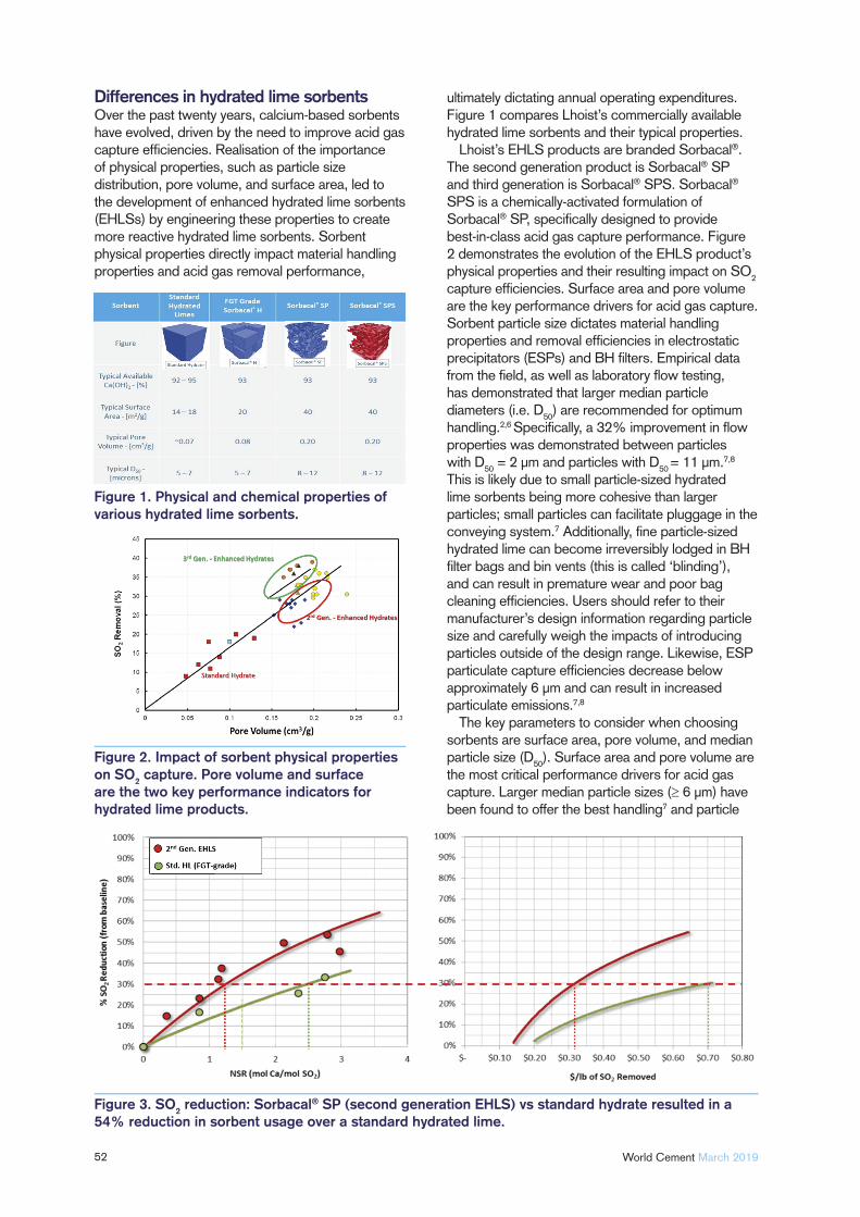
52 World Cement March 2019
Differences in hydrated lime sorbentsOver the past twenty years, calcium-based sorbents have evolved, driven by the need to improve acid gas capture effi ciencies. Realisation of the importance of physical properties, such as particle size distribution, pore volume, and surface area, led to the development of enhanced hydrated lime sorbents (EHLSs) by engineering these properties to create more reactive hydrated lime sorbents. Sorbent physical properties directly impact material handling properties and acid gas removal performance,
ultimately dictating annual operating expenditures. Figure 1 compares Lhoist’s commercially available hydrated lime sorbents and their typical properties.
Lhoist’s EHLS products are branded Sorbacal®. The second generation product is Sorbacal® SP and third generation is Sorbacal® SPS. Sorbacal® SPS is a chemically-activated formulation of Sorbacal® SP, specifi cally designed to provide best-in-class acid gas capture performance. Figure 2 demonstrates the evolution of the EHLS product’s physical properties and their resulting impact on SO
2
capture effi ciencies. Surface area and pore volume are the key performance drivers for acid gas capture. Sorbent particle size dictates material handling properties and removal effi ciencies in electrostatic precipitators (ESPs) and BH fi lters. Empirical data from the fi eld, as well as laboratory fl ow testing, has demonstrated that larger median particle diameters (i.e. D
50) are recommended for optimum
handling.2,6 Specifi cally, a 32% improvement in fl ow properties was demonstrated between particles with D
50 = 2 µm and particles with D
50 = 11 µm.7,8
This is likely due to small particle-sized hydrated lime sorbents being more cohesive than larger particles; small particles can facilitate pluggage in the conveying system.7 Additionally, fi ne particle-sized hydrated lime can become irreversibly lodged in BH fi lter bags and bin vents (this is called ‘blinding’), and can result in premature wear and poor bag cleaning effi ciencies. Users should refer to their manufacturer’s design information regarding particle size and carefully weigh the impacts of introducing particles outside of the design range. Likewise, ESP particulate capture effi ciencies decrease below approximately 6 µm and can result in increased particulate emissions.7,8
The key parameters to consider when choosing sorbents are surface area, pore volume, and median particle size (D
50). Surface area and pore volume are
the most critical performance drivers for acid gas capture. Larger median particle sizes (≥ 6 µm) have been found to offer the best handling7 and particle
Figure 1. Physical and chemical properties of various hydrated lime sorbents.
Figure 2. Impact of sorbent physical properties on SO2 capture. Pore volume and surface are the two key performance indicators for hydrated lime products.
Figure 3. SO2 reduction: Sorbacal® SP (second generation EHLS) vs standard hydrate resulted in a 54% reduction in sorbent usage over a standard hydrated lime.
capture results.7,8 It is noteworthy that ‘available Ca(OH)
2’ impacts acid gas removal performance
to a much lesser extent than surface area and pore volume. This is because sorbent utilisation rates (i.e. the fraction of calcium ions consumed in the reaction) are seldom in excess of 30%.
EHLSs provide the following benefi ts compared to standard hydrated lime:
1. Operating cost savings: EHLSs typically reduce sorbent usage by ≥ 30% over standard hydrated lime sorbents. This results in a lower annual spend on sorbents.
2. Less impact on the ESP/BH fi lter: lower sorbent dosage rates will result in less dust loading to particulate capture equipment. Less dust to an ESP may directly impact particulate collection effi ciency, and for a BH fi lter this could impact bag cleaning cycle frequency. Particle sizes play a critical role in ESP/BH operational effi ciencies. Respective equipment manufacturers should be consulted on particle size guidelines.
3. Fuel and raw material fl exibility: if a lower cost fuel or raw material becomes available but results in increased acid gas emissions, then an EHLS can provide additional fl exibility. This is because it has the ability to achieve higher acid gas removal effi ciencies than standard hydrated limes, without having to modify the existing DSI system.
4. Increased storage silo capacity: lower sorbent consumption using EHLSs results in more days of available storage in a fi xed silo volume. Hence, reducing sorbent consumption by 50% equates to doubling the silo storage capacity.
5. One DSI system for acid gas and Hg control: EHLS blended with PAC is available and precludes the need for two separate systems.
These benefi ts are a result of the EHLS’s engineered and improved physical properties, which are designed to enhance acid gas reactivity.
Choosing the most cost-effective sorbentThe two most critical components when implementing a successful compliance strategy are the following:
Proper sorbent selection. Sorbent distribution in the gas stream.
Assuming that the DSI system is properly designed, installed, and operated,2,6 choosing the most effective sorbent, injection location, and injection grid design are the next critical steps to optimising system cost effectiveness. Although EHLSs are typically more costly than standard sorbents on a delivered basis (i.e. US$/t), higher sorbent effi ciencies often result in an overall lower total cost of ownership. For example, an EHLS may cost 30% more than standard hydrated
W E C O N V E Y Q U A L I T Y
Stockyard Solutions for the Cement Industry
SCHADE Lagertechnik GmbH [email protected] www.schade-lagertechnik.com
no. 143 – Hall B2
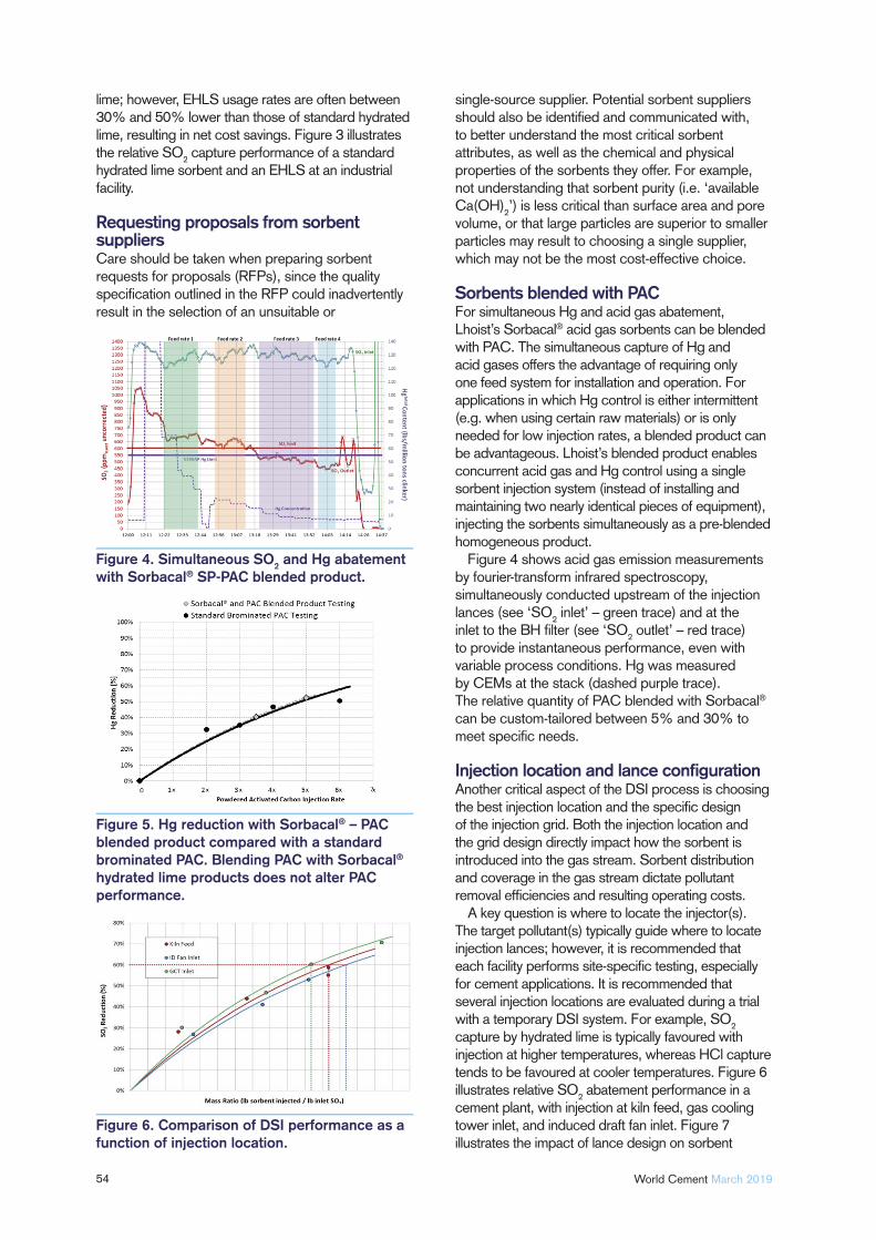
54 World Cement March 2019
lime; however, EHLS usage rates are often between 30% and 50% lower than those of standard hydrated lime, resulting in net cost savings. Figure 3 illustrates the relative SO
2 capture performance of a standard
hydrated lime sorbent and an EHLS at an industrial facility.
Requesting proposals from sorbent suppliersCare should be taken when preparing sorbent requests for proposals (RFPs), since the quality specifi cation outlined in the RFP could inadvertently result in the selection of an unsuitable or
single-source supplier. Potential sorbent suppliers should also be identifi ed and communicated with, to better understand the most critical sorbent attributes, as well as the chemical and physical properties of the sorbents they offer. For example, not understanding that sorbent purity (i.e. ‘available Ca(OH)
2’) is less critical than surface area and pore
volume, or that large particles are superior to smaller particles may result to choosing a single supplier, which may not be the most cost-effective choice.
Sorbents blended with PACFor simultaneous Hg and acid gas abatement, Lhoist’s Sorbacal® acid gas sorbents can be blended with PAC. The simultaneous capture of Hg and acid gases offers the advantage of requiring only one feed system for installation and operation. For applications in which Hg control is either intermittent (e.g. when using certain raw materials) or is only needed for low injection rates, a blended product can be advantageous. Lhoist’s blended product enables concurrent acid gas and Hg control using a single sorbent injection system (instead of installing and maintaining two nearly identical pieces of equipment), injecting the sorbents simultaneously as a pre-blended homogeneous product.
Figure 4 shows acid gas emission measurements by fourier-transform infrared spectroscopy, simultaneously conducted upstream of the injection lances (see ‘SO
2 inlet’ – green trace) and at the
inlet to the BH fi lter (see ‘SO2 outlet’ – red trace)
to provide instantaneous performance, even with variable process conditions. Hg was measured by CEMs at the stack (dashed purple trace). The relative quantity of PAC blended with Sorbacal®
can be custom-tailored between 5% and 30% to meet specifi c needs.
Injection location and lance confi gurationAnother critical aspect of the DSI process is choosing the best injection location and the specifi c design of the injection grid. Both the injection location and the grid design directly impact how the sorbent is introduced into the gas stream. Sorbent distribution and coverage in the gas stream dictate pollutant removal effi ciencies and resulting operating costs.
A key question is where to locate the injector(s). The target pollutant(s) typically guide where to locate injection lances; however, it is recommended that each facility performs site-specifi c testing, especially for cement applications. It is recommended that several injection locations are evaluated during a trial with a temporary DSI system. For example, SO
2
capture by hydrated lime is typically favoured with injection at higher temperatures, whereas HCl capture tends to be favoured at cooler temperatures. Figure 6 illustrates relative SO
2 abatement performance in a
cement plant, with injection at kiln feed, gas cooling tower inlet, and induced draft fan inlet. Figure 7 illustrates the impact of lance design on sorbent
Figure 6. Comparison of DSI performance as a function of injection location.
Figure 5. Hg reduction with Sorbacal® – PAC blended product compared with a standard brominated PAC. Blending PAC with Sorbacal®
hydrated lime products does not alter PAC performance.
Figure 4. Simultaneous SO2 and Hg abatement with Sorbacal® SP-PAC blended product.
performance. Without a trial to determine the best injection location, incorrect injector location selection can result in higher usage rates and annual costs.
Once the injection location is determined, the injection grid design is the next key performance driver. Injection grid designs can be as simple as a single injection lance or as complicated as a multi-lance design with various penetration depths. Over the past few years, new injection technologies have emerged, signifi cantly improving sorbent distribution within the gas stream and reducing sorbent consumption. These systems can result in operating cost savings with a relatively quick return on investment. Computational fl uid dynamics modelling is a benefi cial tool that can be used to guide the injection grid design, in order to optimise sorbent distribution. In-duct cameras can also be employed to visually inspect sorbent distribution following system installation, and to corroborate good distribution by identifying distribution ineffi ciencies.
Figure 6 shows a comparison of Sorbacal® being injected at the following three locations: with kiln feed, at the gas cooling tower inlet, and at the induced draft fan inlet. Note: these results do not always translate from plant to plant. It is critical to evaluate different injection locations at each plant to fi nd the optimal injection location.
Figure 8 is a photograph taken with an in-duct camera inserted into the gas stream to evaluate sorbent dispersion during a full-scale DSI fi eld trial.
Images were recorded upstream of the injection lance(s), which were located between an ESP and a BH. (A) illustrates the poor sorbent distribution with the original single-lance confi guration. The area in red highlights the white sorbent plume. (B) illustrates the improved sorbent distribution with the addition of lance (for a total of six). Additionally, fl ow was balanced by modulating dampers at the BH clean air plenum. Originally, fl ow in this duct was highly stratifi ed (as verifi ed with pitot tube measurements); fl ow balancing and the addition of lances resulted in a cloud of sorbent distributed across the duct.
ConclusionSorbent selection, proper location of injectors, and injector grid/lance design are the most critical parameters that determine overall DSI system effi ciency. Over the past two decades, EHLSs have been specifi cally optimised for acid gas abatement applications. In the past, sorbent selection was driven by geologically-dictated hydrated lime purity (i.e. available Ca(OH)
2). Today, sorbent purity has little
impact on performance, and sorbent performance is primarily driven by porosity (i.e. surface area and pore volume). Additionally, blended sorbents (PAC and EHLS in one sorbent) can reduce system costs because only one injection system is needed. EHLS particle sizes have been optimised for superior material handling and particulate capture by BH fi lters and/or precipitators (i.e. larger particles are better).
(SEMI) TURNKEY GRINDING PLANTS | MILLSROTARY DRYERS | HOT GAS GENERATORSSEPARATORS | ONLINE PARTICLE SIZE ANALYSERS
CEMENT MILLS
Ennshafenstraße 40 4470 Enns. Austria T +43/7223/83620-0
www.cemtec.at
CEMTEC provides the right solution for customers in the cement industry and will meet customers’ requirements without objection. Projects undertaken by CEMTEC range from single machines to turnkey plants, from engineering to commissioning and after-sales service.
Competent employees and professional facilities, such as the workshop and the laboratory which enable appropriate product investigations and test runs, ensure successful fulfillment of the particular assignment.
Visit us: POWTECH, 9-11 APRIL at the Nuremberg exhibition center.
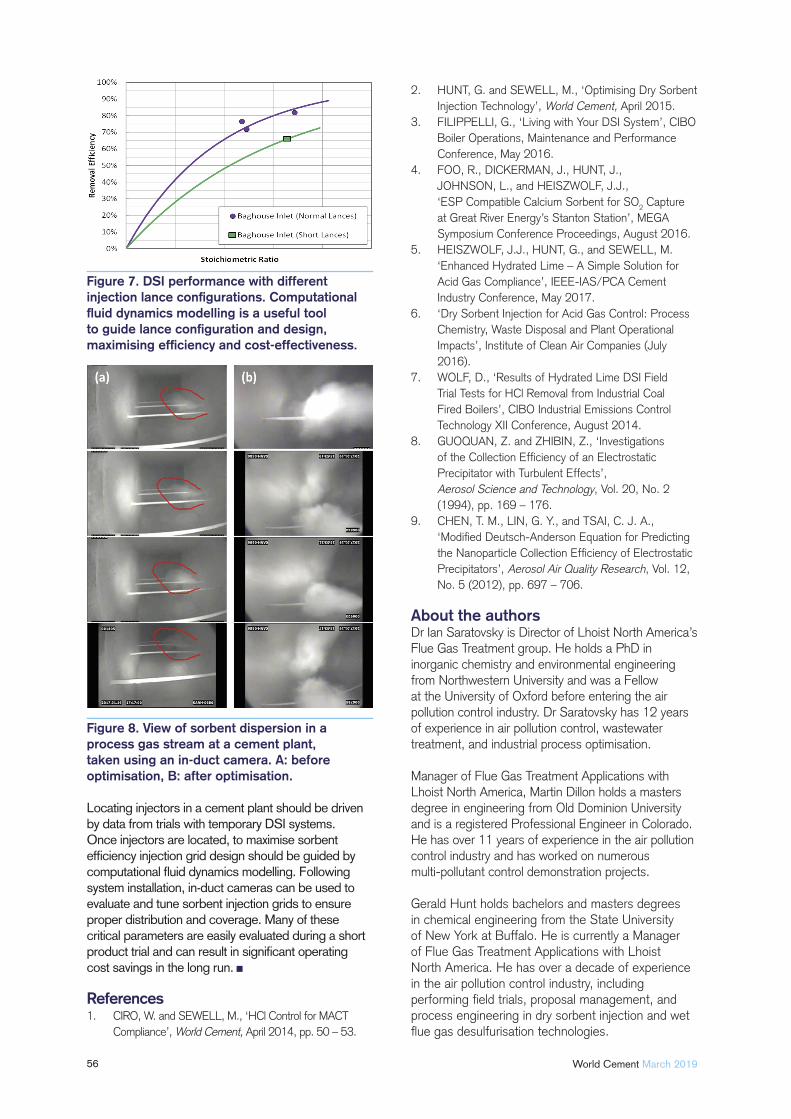
56 World Cement March 2019
Locating injectors in a cement plant should be driven by data from trials with temporary DSI systems. Once injectors are located, to maximise sorbent effi ciency injection grid design should be guided by computational fl uid dynamics modelling. Following system installation, in-duct cameras can be used to evaluate and tune sorbent injection grids to ensure proper distribution and coverage. Many of these critical parameters are easily evaluated during a short product trial and can result in signifi cant operating cost savings in the long run.
References1. CIRO, W. and SEWELL, M., ‘HCl Control for MACT
Compliance’, World Cement, April 2014, pp. 50 – 53.
2. HUNT, G. and SEWELL, M., ‘Optimising Dry Sorbent
Injection Technology’, World Cement, April 2015.
3. FILIPPELLI, G., ‘Living with Your DSI System’, CIBO
Boiler Operations, Maintenance and Performance
Conference, May 2016.
4. FOO, R., DICKERMAN, J., HUNT, J.,
JOHNSON, L., and HEISZWOLF, J.J.,
‘ESP Compatible Calcium Sorbent for SO2 Capture
at Great River Energy’s Stanton Station’, MEGA
Symposium Conference Proceedings, August 2016.
5. HEISZWOLF, J.J., HUNT, G., and SEWELL, M.
‘Enhanced Hydrated Lime – A Simple Solution for
Acid Gas Compliance’, IEEE-IAS/PCA Cement
Industry Conference, May 2017.
6. ‘Dry Sorbent Injection for Acid Gas Control: Process
Chemistry, Waste Disposal and Plant Operational
Impacts’, Institute of Clean Air Companies (July
2016).
7. WOLF, D., ‘Results of Hydrated Lime DSI Field
Trial Tests for HCl Removal from Industrial Coal
Fired Boilers’, CIBO Industrial Emissions Control
Technology XII Conference, August 2014.
8. GUOQUAN, Z. and ZHIBIN, Z., ‘Investigations
of the Collection Effi ciency of an Electrostatic
Precipitator with Turbulent Effects’,
Aerosol Science and Technology, Vol. 20, No. 2
(1994), pp. 169 – 176.
9. CHEN, T. M., LIN, G. Y., and TSAI, C. J. A.,
‘Modifi ed Deutsch-Anderson Equation for Predicting
the Nanoparticle Collection Effi ciency of Electrostatic
Precipitators’, Aerosol Air Quality Research, Vol. 12,
No. 5 (2012), pp. 697 – 706.
About the authorsDr Ian Saratovsky is Director of Lhoist North America’s Flue Gas Treatment group. He holds a PhD in inorganic chemistry and environmental engineering from Northwestern University and was a Fellow at the University of Oxford before entering the air pollution control industry. Dr Saratovsky has 12 years of experience in air pollution control, wastewater treatment, and industrial process optimisation.
Manager of Flue Gas Treatment Applications with Lhoist North America, Martin Dillon holds a masters degree in engineering from Old Dominion University and is a registered Professional Engineer in Colorado. He has over 11 years of experience in the air pollution control industry and has worked on numerous multi-pollutant control demonstration projects.
Gerald Hunt holds bachelors and masters degrees in chemical engineering from the State University of New York at Buffalo. He is currently a Manager of Flue Gas Treatment Applications with Lhoist North America. He has over a decade of experience in the air pollution control industry, including performing fi eld trials, proposal management, and process engineering in dry sorbent injection and wet fl ue gas desulfurisation technologies.
Figure 8. View of sorbent dispersion in a process gas stream at a cement plant, taken using an in-duct camera. A: before optimisation, B: after optimisation.
Figure 7. DSI performance with different injection lance confi gurations. Computational fl uid dynamics modelling is a useful tool to guide lance confi guration and design, maximising effi ciency and cost-effectiveness.
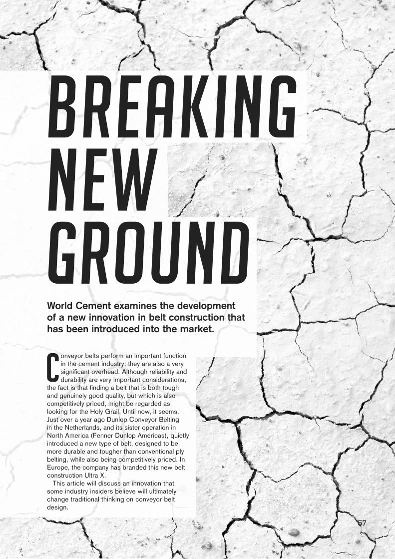
57
Breaking New GroundWorld Cement examines the development of a new innovation in belt construction that has been introduced into the market.
Conveyor belts perform an important function in the cement industry; they are also a very signifi cant overhead. Although reliability and durability are very important considerations,
the fact is that fi nding a belt that is both tough and genuinely good quality, but which is also competitively priced, might be regarded as looking for the Holy Grail. Until now, it seems. Just over a year ago Dunlop Conveyor Belting in the Netherlands, and its sister operation in North America (Fenner Dunlop Americas), quietly introduced a new type of belt, designed to be more durable and tougher than conventional ply belting, while also being competitively priced. In Europe, the company has branded this new belt construction Ultra X.
This article will discuss an innovation that some industry insiders believe will ultimately change traditional thinking on conveyor belt design.
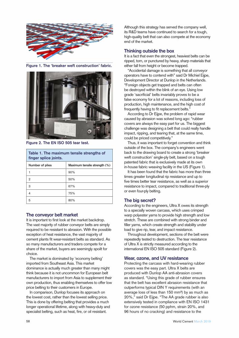
58 World Cement March 2019
The conveyor belt marketIt is important to fi rst look at the market backdrop. The vast majority of rubber conveyor belts are simply required to be resistant to abrasion. With the possible exception of heat resistance, the vast majority of cement plants fi t wear-resistant belts as standard. As so many manufacturers and traders compete for a share of the market, buyers are seemingly spoilt for choice.
The market is dominated by ‘economy belting’ imported from Southeast Asia. This market dominance is actually much greater than many might think because it is not uncommon for European belt manufacturers to import from Asia to supplement their own production, thus enabling themselves to offer low price belting to their customers in Europe.
In comparison, Dunlop focuses its approach on the lowest cost, rather than the lowest selling price. This is done by offering belting that provides a much longer operational lifetime, along with heavy-duty and specialist belting, such as heat, fi re, or oil resistant.
Although this strategy has served the company well, its R&D teams have continued to search for a tough, high-quality belt that can also compete at the economy end of the market.
Thinking outside the boxIt is a fact that even the strongest, heaviest belts can be ripped, torn, or punctured by heavy, sharp materials that either fall from height or become trapped.
“Accidental damage is something that all conveyor operators have to contend with” said Dr Michiel Eijpe, Development Director at Dunlop in the Netherlands. “Foreign objects get trapped and belts can often be destroyed within the blink of an eye. Using low grade ‘sacrifi cial’ belts invariably proves to be a false economy for a lot of reasons, including loss of production, high maintenance, and the high cost of frequently having to fi t replacement belts.”
According to Dr Eijpe, the problem of rapid wear caused by abrasion was solved long ago: “rubber covers are always the easy part for us. The biggest challenge was designing a belt that could really handle impact, ripping, and tearing that, at the same time, could be priced competitively.”
Thus, it was important to forget convention and think outside of the box. The company’s engineers went back to the drawing board to create a strong ‘breaker weft construction’ single-ply belt, based on a tough patented fabric that is exclusively made at its own in-house fabric weaving facility in the US (Figure 1).
It has been found that the fabric has more than three times greater longitudinal rip resistance and up to fi ve times better tear resistance, as well as a superior resistance to impact, compared to traditional three-ply or even four-ply belting.
The big secret?According to the engineers, Ultra X owes its strength to a specially woven carcass, which uses crimped warp polyester yarns to provide high strength and low stretch. These are combined with strong binder and fi ller yarns, which create strength and stability under load to give rip, tear, and impact resistance.
Throughout development, sections of the belt were repeatedly tested to destruction. The tear resistance of Ultra X is strictly measured according to the international EN ISO 505 standard (Figure 2).
Wear, ozone, and UV resistanceProtecting the carcass with hard-wearing rubber covers was the easy part. Ultra X belts are produced with Dunlop AA anti-abrasion covers as standard. “Using this grade of rubber ensures that the belt has excellent abrasion resistance that outperforms typical DIN Y requirements (with an average loss of less than 150 mm³) by as much as 20%,” said Dr Eijpe. “The AA grade rubber is also extensively tested in compliance with EN ISO 1431 for ozone resistance (50 pphm, strain 20%, and 96 hours of no cracking) and resistance to the
Figure 2. The EN ISO 505 tear test.
Figure 1. The ‘breaker weft construction’ fabric.
Table 1. The maximum tensile strengths of fi nger splice joints.
Number of plies Maximum tensile strength (%)
1 90%
2 50%
3 67%
4 75%
5 80%
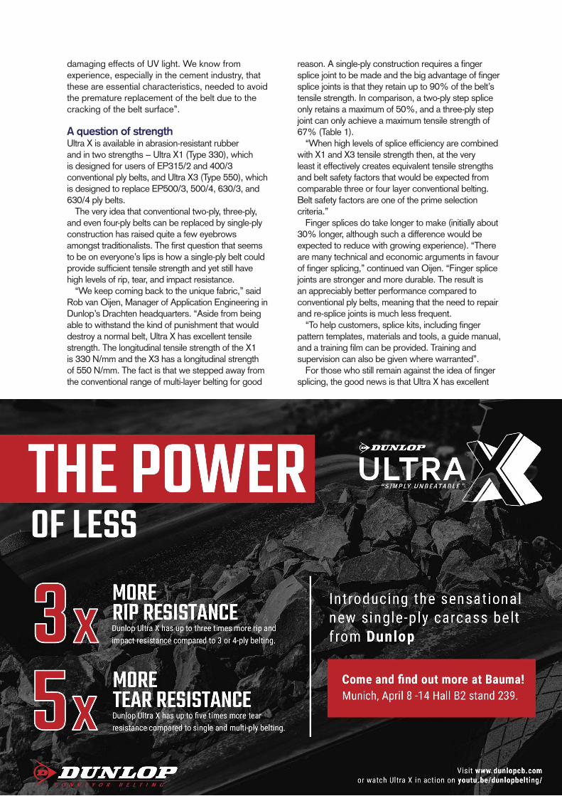
damaging effects of UV light. We know from experience, especially in the cement industry, that these are essential characteristics, needed to avoid the premature replacement of the belt due to the cracking of the belt surface”.
A question of strengthUltra X is available in abrasion-resistant rubber and in two strengths − Ultra X1 (Type 330), which is designed for users of EP315/2 and 400/3 conventional ply belts, and Ultra X3 (Type 550), which is designed to replace EP500/3, 500/4, 630/3, and 630/4 ply belts.
The very idea that conventional two-ply, three-ply, and even four-ply belts can be replaced by single-ply construction has raised quite a few eyebrows amongst traditionalists. The fi rst question that seems to be on everyone’s lips is how a single-ply belt could provide suffi cient tensile strength and yet still have high levels of rip, tear, and impact resistance.
“We keep coming back to the unique fabric,” said Rob van Oijen, Manager of Application Engineering in Dunlop’s Drachten headquarters. “Aside from being able to withstand the kind of punishment that would destroy a normal belt, Ultra X has excellent tensile strength. The longitudinal tensile strength of the X1 is 330 N/mm and the X3 has a longitudinal strength of 550 N/mm. The fact is that we stepped away from the conventional range of multi-layer belting for good
reason. A single-ply construction requires a fi nger splice joint to be made and the big advantage of fi nger splice joints is that they retain up to 90% of the belt’s tensile strength. In comparison, a two-ply step splice only retains a maximum of 50%, and a three-ply step joint can only achieve a maximum tensile strength of 67% (Table 1).
“When high levels of splice effi ciency are combined with X1 and X3 tensile strength then, at the very least it effectively creates equivalent tensile strengths and belt safety factors that would be expected from comparable three or four layer conventional belting. Belt safety factors are one of the prime selection criteria.”
Finger splices do take longer to make (initially about 30% longer, although such a difference would be expected to reduce with growing experience). “There are many technical and economic arguments in favour of fi nger splicing,” continued van Oijen. “Finger splice joints are stronger and more durable. The result is an appreciably better performance compared to conventional ply belts, meaning that the need to repair and re-splice joints is much less frequent.
“To help customers, splice kits, including fi nger pattern templates, materials and tools, a guide manual, and a training fi lm can be provided. Training and supervision can also be given where warranted”.
For those who still remain against the idea of fi nger splicing, the good news is that Ultra X has excellent
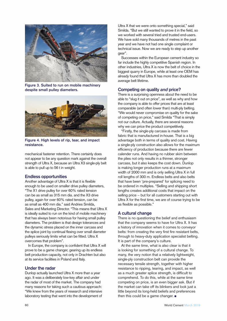
60 World Cement March 2019
mechanical fastener retention. There certainly does not appear to be any question mark against the overall strength of Ultra X, because an Ultra X3 single-ply belt is able to pull up to 56 t in weight.
Endless opportunitiesAnother advantage of Ultra X is that it is fl exible enough to be used on smaller drive pulley diameters, “The X1 drive pulley for over 60% rated tension can be as small as 315 mm dia. and the X3 drive pulley, again for over 60% rated tension, can be as small as 400 mm dia.” said Andries Smilda, Sales and Marketing Director. “This means that Ultra X is ideally suited to run on the kind of mobile machinery that has always been notorious for having small pulley diameters. The problem is that design tolerances and the dynamic stress placed on the inner carcass and the splice joint by continual fl exing over small diameter pulleys seriously limits what can be fi tted. Ultra X overcomes that problem”.
In Europe, the company is confi dent that Ultra X will prove to be a game changer, gearing up its endless belt production capacity, not only in Drachten but also at its service facilities in Poland and Italy.
Under the radarDunlop actually launched Ultra X more than a year ago. It was a deliberately low-key affair and under the radar of most of the market. The company had many reasons for taking such a cautious approach: “We knew from the years of research and intensive laboratory testing that went into the development of
Ultra X that we were onto something special,” said Smilda. “But we still wanted to prove it in the fi eld, so we worked with several tried and trusted end-users. We have sold many thousands of metres in the past year and we have not had one single complaint or technical issue. Now we are ready to step up another gear”.
Successes within the European cement industry so far include the highly competitive Spanish region. In other industries, Ultra X is now the belt of choice in the biggest quarry in Europe, while at least one OEM has already found that Ultra X has more than doubled the average belt lifetime.
Competing on quality and price?There is a surprising openness about the need to be able to “slug it out on price”, as well as why and how the company is able to offer prices that are at least comparable (and often lower than) multi-ply belting. “We would never compromise on quality for the sake of competing on price,” said Smilda “That is simply not our culture. Actually, there are several reasons why we can price the product competitively.
“Firstly, the single-ply carcass is made from fabric that is manufactured in-house. That is a big advantage both in terms of quality and cost. Having a single-ply construction also allows for the maximum effi ciency of production because there are fewer calender runs. And having no rubber skim between the plies not only results in a thinner, stronger carcass, but it also keeps the cost down. Dunlop is making longer production runs at a maximum width of 2000 mm and is only selling Ultra X in full roll lengths of 300 m. Endless belts and also belts that have been ‘pre-prepared’ for splicing need to be ordered in multiples. “Selling and shipping short lengths creates additional costs that impact on the selling price − but for all customers starting out with Ultra X for the fi rst time, we are of course trying to be as fl exible as possible.”
A cultural changeThere is no questioning the belief and enthusiasm that the company seems to have for Ultra X. It has a history of innovation when it comes to conveyor belts: from creating the very fi rst fi re resistant belts, through to heavy-duty application specialist belting. It is part of the company’s culture.
At the same time, what is also clear is that it is looking for something of a cultural change. To many, the very notion that a relatively lightweight, single-ply construction belt can provide the necessary tensile strength, together with higher resistance to ripping, tearing, and impact, as well as a much greater splice strength, is diffi cult to comprehend. To do this, while at the same time competing on price, is an even bigger ask. But if the market can take off its blinkers and look just a little beyond its long-held beliefs and preferences then this could be a game changer.
Figure 4. High levels of rip, tear, and impact resistance.
Figure 3. Suited to run on mobile machinery despite small pulley diameters.
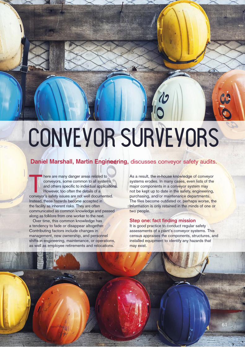
Conveyor surveyorsConveyor surveyors
61
Daniel Marshall, Martin Engineering, discusses conveyor safety audits.
There are many danger areas related to conveyors, some common to all systems and others specifi c to individual applications. However, too often the details of a
conveyor’s safety issues are not well documented. Instead, these hazards become accepted in the facility as inherent risks. They are often communicated as common knowledge and passed along as folklore from one worker to the next.
Over time, this common knowledge has a tendency to fade or disappear altogether. Contributing factors include changes in management, new ownership, and personnel shifts in engineering, maintenance, or operations, as well as employee retirements and relocations.
As a result, the in-house knowledge of conveyor systems erodes. In many cases, even lists of the major components in a conveyor system may not be kept up to date in the safety, engineering, purchasing, and/or maintenance departments. The fi les become outdated or, perhaps worse, the information is only retained in the minds of one or two people.
Step one: fact fi nding missionIt is good practice to conduct regular safety assessments of a plant’s conveyor systems. This census appraises the components, structures, and installed equipment to identify any hazards that may exist.
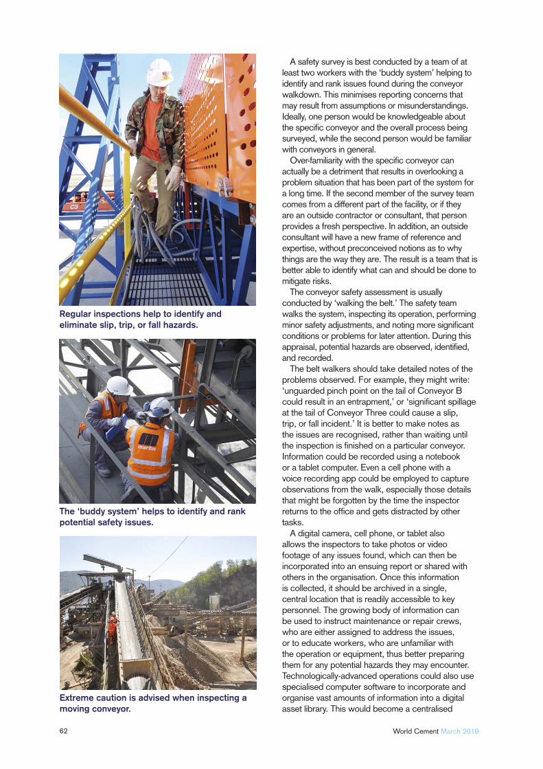
62 World Cement March 2019
A safety survey is best conducted by a team of at least two workers with the ‘buddy system’ helping to identify and rank issues found during the conveyor walkdown. This minimises reporting concerns that may result from assumptions or misunderstandings. Ideally, one person would be knowledgeable about the specifi c conveyor and the overall process being surveyed, while the second person would be familiar with conveyors in general.
Over-familiarity with the specifi c conveyor can actually be a detriment that results in overlooking a problem situation that has been part of the system for a long time. If the second member of the survey team comes from a different part of the facility, or if they are an outside contractor or consultant, that person provides a fresh perspective. In addition, an outside consultant will have a new frame of reference and expertise, without preconceived notions as to why things are the way they are. The result is a team that is better able to identify what can and should be done to mitigate risks.
The conveyor safety assessment is usually conducted by ‘walking the belt.’ The safety team walks the system, inspecting its operation, performing minor safety adjustments, and noting more signifi cant conditions or problems for later attention. During this appraisal, potential hazards are observed, identifi ed, and recorded.
The belt walkers should take detailed notes of the problems observed. For example, they might write: ‘unguarded pinch point on the tail of Conveyor B could result in an entrapment,’ or ‘signifi cant spillage at the tail of Conveyor Three could cause a slip, trip, or fall incident.’ It is better to make notes as the issues are recognised, rather than waiting until the inspection is fi nished on a particular conveyor. Information could be recorded using a notebook or a tablet computer. Even a cell phone with a voice recording app could be employed to capture observations from the walk, especially those details that might be forgotten by the time the inspector returns to the offi ce and gets distracted by other tasks.
A digital camera, cell phone, or tablet also allows the inspectors to take photos or video footage of any issues found, which can then be incorporated into an ensuing report or shared with others in the organisation. Once this information is collected, it should be archived in a single, central location that is readily accessible to key personnel. The growing body of information can be used to instruct maintenance or repair crews, who are either assigned to address the issues, or to educate workers, who are unfamiliar with the operation or equipment, thus better preparing them for any potential hazards they may encounter. Technologically-advanced operations could also use specialised computer software to incorporate and organise vast amounts of information into a digital asset library. This would become a centralised
Regular inspections help to identify and eliminate slip, trip, or fall hazards.
The ‘buddy system’ helps to identify and rank potential safety issues.
Extreme caution is advised when inspecting a moving conveyor.
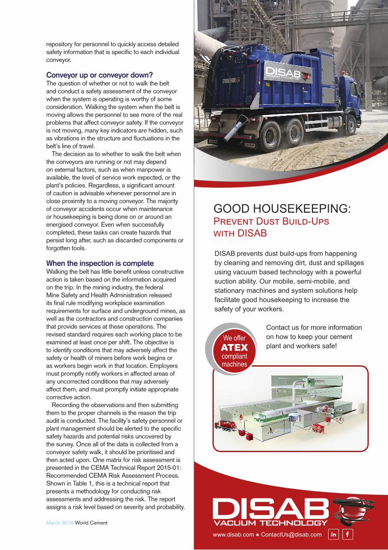
March 2019 World Cement
repository for personnel to quickly access detailed safety information that is specifi c to each individual conveyor.
Conveyor up or conveyor down?The question of whether or not to walk the belt and conduct a safety assessment of the conveyor when the system is operating is worthy of some consideration. Walking the system when the belt is moving allows the personnel to see more of the real problems that affect conveyor safety. If the conveyor is not moving, many key indicators are hidden, such as vibrations in the structure and fl uctuations in the belt’s line of travel.
The decision as to whether to walk the belt when the conveyors are running or not may depend on external factors, such as when manpower is available, the level of service work expected, or the plant’s policies. Regardless, a signifi cant amount of caution is advisable whenever personnel are in close proximity to a moving conveyor. The majority of conveyor accidents occur when maintenance or housekeeping is being done on or around an energised conveyor. Even when successfully completed, these tasks can create hazards that persist long after, such as discarded components or forgotten tools.
When the inspection is completeWalking the belt has little benefi t unless constructive action is taken based on the information acquired on the trip. In the mining industry, the federal Mine Safety and Health Administration released its fi nal rule modifying workplace examination requirements for surface and underground mines, as well as the contractors and construction companies that provide services at these operations. The revised standard requires each working place to be examined at least once per shift. The objective is to identify conditions that may adversely affect the safety or health of miners before work begins or as workers begin work in that location. Employers must promptly notify workers in affected areas of any uncorrected conditions that may adversely affect them, and must promptly initiate appropriate corrective action.
Recording the observations and then submitting them to the proper channels is the reason the trip audit is conducted. The facility’s safety personnel or plant management should be alerted to the specifi c safety hazards and potential risks uncovered by the survey. Once all of the data is collected from a conveyor safety walk, it should be prioritised and then acted upon. One matrix for risk assessment is presented in the CEMA Technical Report 2015-01: Recommended CEMA Risk Assessment Process. Shown in Table 1, this is a technical report that presents a methodology for conducting risk assessments and addressing the risk. The report assigns a risk level based on severity and probability.
DISAB prevents dust build-ups from happening by cleaning and removing dirt, dust and spillages using vacuum based technology with a powerful suction ability. Our mobile, semi-mobile, and stationary machines and system solutions help facilitate good housekeeping to increase the safety of your workers.
Contact us for more information on how to keep your cement plant and workers safe!
We offerATEX compliant machines
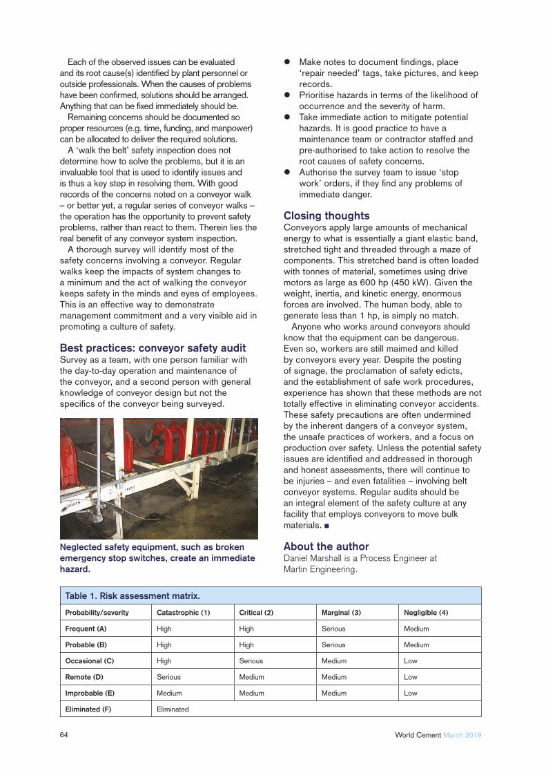
64 World Cement March 2019
Each of the observed issues can be evaluated and its root cause(s) identifi ed by plant personnel or outside professionals. When the causes of problems have been confi rmed, solutions should be arranged. Anything that can be fi xed immediately should be.
Remaining concerns should be documented so proper resources (e.g. time, funding, and manpower) can be allocated to deliver the required solutions.
A ‘walk the belt’ safety inspection does not determine how to solve the problems, but it is an invaluable tool that is used to identify issues and is thus a key step in resolving them. With good records of the concerns noted on a conveyor walk – or better yet, a regular series of conveyor walks – the operation has the opportunity to prevent safety problems, rather than react to them. Therein lies the real benefi t of any conveyor system inspection.
A thorough survey will identify most of the safety concerns involving a conveyor. Regular walks keep the impacts of system changes to a minimum and the act of walking the conveyor keeps safety in the minds and eyes of employees. This is an effective way to demonstrate management commitment and a very visible aid in promoting a culture of safety.
Best practices: conveyor safety auditSurvey as a team, with one person familiar with the day-to-day operation and maintenance of the conveyor, and a second person with general knowledge of conveyor design but not the specifi cs of the conveyor being surveyed.
Make notes to document fi ndings, place ‘repair needed’ tags, take pictures, and keep records.
Prioritise hazards in terms of the likelihood of occurrence and the severity of harm.
Take immediate action to mitigate potential hazards. It is good practice to have a maintenance team or contractor staffed and pre-authorised to take action to resolve the root causes of safety concerns.
Authorise the survey team to issue ‘stop work’ orders, if they fi nd any problems of immediate danger.
Closing thoughtsConveyors apply large amounts of mechanical energy to what is essentially a giant elastic band, stretched tight and threaded through a maze of components. This stretched band is often loaded with tonnes of material, sometimes using drive motors as large as 600 hp (450 kW). Given the weight, inertia, and kinetic energy, enormous forces are involved. The human body, able to generate less than 1 hp, is simply no match.
Anyone who works around conveyors should know that the equipment can be dangerous. Even so, workers are still maimed and killed by conveyors every year. Despite the posting of signage, the proclamation of safety edicts, and the establishment of safe work procedures, experience has shown that these methods are not totally effective in eliminating conveyor accidents. These safety precautions are often undermined by the inherent dangers of a conveyor system, the unsafe practices of workers, and a focus on production over safety. Unless the potential safety issues are identifi ed and addressed in thorough and honest assessments, there will continue to be injuries – and even fatalities – involving belt conveyor systems. Regular audits should be an integral element of the safety culture at any facility that employs conveyors to move bulk materials.
About the authorDaniel Marshall is a Process Engineer at Martin Engineering.
Neglected safety equipment, such as broken emergency stop switches, create an immediate hazard.
Table 1. Risk assessment matrix.
Probability/severity Catastrophic (1) Critical (2) Marginal (3) Negligible (4)
Frequent (A) High High Serious Medium
Probable (B) High High Serious Medium
Occasional (C) High Serious Medium Low
Remote (D) Serious Medium Medium Low
Improbable (E) Medium Medium Medium Low
Eliminated (F) Eliminated

Between Two
Towers
65
Doppelmayr talks to World Cement about the
transportation of limestone across treetops in Guatemala.
As part of its San Gabriel cement plant project, located in southeastern
Guatemala approximately 35 km from the country’s capital, Cementos Progreso SA opted for a RopeCon® system to transport approximately 2100 tph of limestone from the crusher to the processing plant. RopeCon is a product developed by Austrian ropeway manufacturer Doppelmayr. The countryside around the village of San Juan Sacatepéquez is hilly and forested, but RopeCon is well-suited to such hilly and wooded areas, as it combines the benefits of a belt conveyor with those of a cable car.
The RopeCon systemThe system essentially consists of a cross-reinforced endless flat belt with corrugated
The RopeCon® easily crosses obstacles of various kinds.
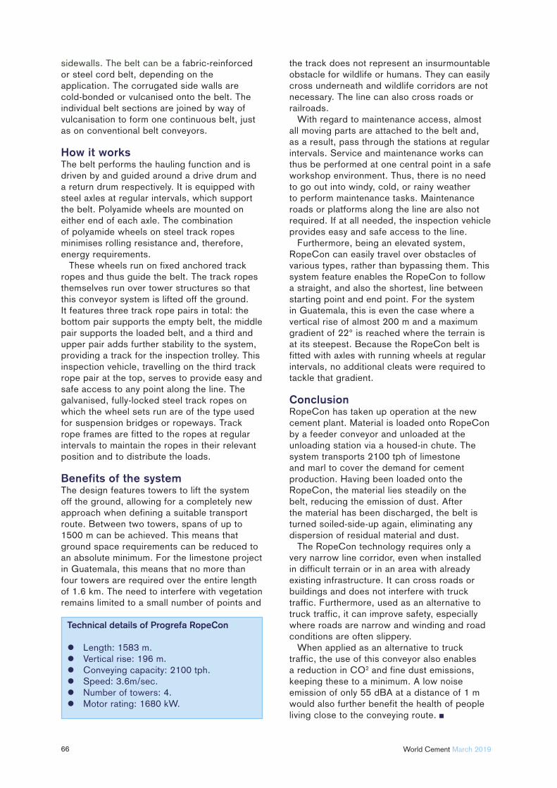
66 World Cement March 2019
sidewalls. The belt can be a fabric-reinforced or steel cord belt, depending on the application. The corrugated side walls are cold-bonded or vulcanised onto the belt. The individual belt sections are joined by way of vulcanisation to form one continuous belt, just as on conventional belt conveyors.
How it worksThe belt performs the hauling function and is driven by and guided around a drive drum and a return drum respectively. It is equipped with steel axles at regular intervals, which support the belt. Polyamide wheels are mounted on either end of each axle. The combination of polyamide wheels on steel track ropes minimises rolling resistance and, therefore, energy requirements.
These wheels run on fixed anchored track ropes and thus guide the belt. The track ropes themselves run over tower structures so that this conveyor system is lifted off the ground. It features three track rope pairs in total: the bottom pair supports the empty belt, the middle pair supports the loaded belt, and a third and upper pair adds further stability to the system, providing a track for the inspection trolley. This inspection vehicle, travelling on the third track rope pair at the top, serves to provide easy and safe access to any point along the line. The galvanised, fully-locked steel track ropes on which the wheel sets run are of the type used for suspension bridges or ropeways. Track rope frames are fitted to the ropes at regular intervals to maintain the ropes in their relevant position and to distribute the loads.
Benefits of the systemThe design features towers to lift the system off the ground, allowing for a completely new approach when defining a suitable transport route. Between two towers, spans of up to 1500 m can be achieved. This means that ground space requirements can be reduced to an absolute minimum. For the limestone project in Guatemala, this means that no more than four towers are required over the entire length of 1.6 km. The need to interfere with vegetation remains limited to a small number of points and
the track does not represent an insurmountable obstacle for wildlife or humans. They can easily cross underneath and wildlife corridors are not necessary. The line can also cross roads or railroads.
With regard to maintenance access, almost all moving parts are attached to the belt and, as a result, pass through the stations at regular intervals. Service and maintenance works can thus be performed at one central point in a safe workshop environment. Thus, there is no need to go out into windy, cold, or rainy weather to perform maintenance tasks. Maintenance roads or platforms along the line are also not required. If at all needed, the inspection vehicle provides easy and safe access to the line.
Furthermore, being an elevated system, RopeCon can easily travel over obstacles of various types, rather than bypassing them. This system feature enables the RopeCon to follow a straight, and also the shortest, line between starting point and end point. For the system in Guatemala, this is even the case where a vertical rise of almost 200 m and a maximum gradient of 22° is reached where the terrain is at its steepest. Because the RopeCon belt is fitted with axles with running wheels at regular intervals, no additional cleats were required to tackle that gradient.
ConclusionRopeCon has taken up operation at the new cement plant. Material is loaded onto RopeCon by a feeder conveyor and unloaded at the unloading station via a housed-in chute. The system transports 2100 tph of limestone and marl to cover the demand for cement production. Having been loaded onto the RopeCon, the material lies steadily on the belt, reducing the emission of dust. After the material has been discharged, the belt is turned soiled-side-up again, eliminating any dispersion of residual material and dust.
The RopeCon technology requires only a very narrow line corridor, even when installed in difficult terrain or in an area with already existing infrastructure. It can cross roads or buildings and does not interfere with truck traffic. Furthermore, used as an alternative to truck traffic, it can improve safety, especially where roads are narrow and winding and road conditions are often slippery.
When applied as an alternative to truck traffic, the use of this conveyor also enables a reduction in CO2 and fine dust emissions, keeping these to a minimum. A low noise emission of only 55 dBA at a distance of 1 m would also further benefit the health of people living close to the conveying route.
Technical details of Progrefa RopeCon
Length: 1583 m. Vertical rise: 196 m. Conveying capacity: 2100 tph. Speed: 3.6m/sec. Number of towers: 4. Motor rating: 1680 kW.

SOLID SILOS
67
Mario Scutti, SCUTTI, discusses the advantages and disadvantages of various silos for bulk solids.
The variety of materials stored in silos is enormous. While larger silos are used for grain or cement, smaller silos store anything from hay silage on farms, to ultrafi ne powders
in the processing industry. Most materials stored in silos are considered ‘granular’; this article will use the relatively unbiased term ‘bulk solid’ for the material stored in silos.
The number of different constitutive models for bulk solids is extensive, but this article will focus on cylindrical silos for vertical storage. Most of these have been designed by professional engineers according to the experience gained in their specifi c fi elds, and are manufactured by companies producing generic
steel fabrications. It is important to consider that the market consists of a wide range of steel silos made by specialised companies, such as SCUTTI. These silos are already developed in standard sizes, for different storage capacities that can be easily adapted to the specifi c needs of the customer.
This article will focus on silos for bulk solids, manufactured by specialised companies and which are used in the processing industries. In the last few years, the demand for small and medium storage plants has increased because of the development of emerging markets across the globe. In this scenario, a common question that almost all the companies ask themselves before
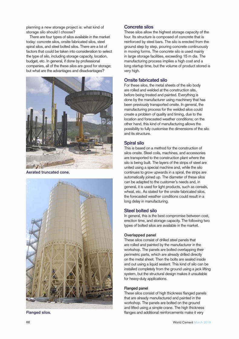
68 World Cement March 2019
planning a new storage project is: what kind of storage silo should I choose?
There are four types of silos available in the market today: concrete silos, onsite fabricated silos, steel spiral silos, and steel bolted silos. There are a lot of factors that could be taken into consideration to select the type of silo, including storage capacity, location, budget, etc. In general, if done by professional companies, all of the these silos are good for storage; but what are the advantages and disadvantages?
Concrete silosThese silos allow the highest storage capacity of the four. Its structure is composed of concrete that is reinforced by steel bars. The silo is erected from the ground step by step, pouring concrete continuously in moving forms. The concrete silo is used mainly in large storage facilities, exceeding 15 m dia. The manufacturing process implies a high cost and a long startup time, but the volume of product stored is very high.
Onsite fabricated silo For these silos, the metal sheets of the silo body are rolled and welded at the construction site, before being treated and painted. Everything is done by the manufacturer using machinery that has been previously transported onsite. In general, the manufacturing process for the welded silos could create a problem of quality and timing, due to the location and forecasted weather conditions; on the other hand, this kind of manufacturing allows the possibility to fully customise the dimensions of the silo and its structure.
Spiral silo This is based on a method for the construction of silos onsite. Steel coils, machines, and accessories are transported to the construction plant where the silo is being built. The layers of the strips of steel are united using a special machine and, while the silo continues to grow upwards in a spiral, the strips are automatically joined up. The diameter of these silos can be adapted to the customer’s needs and, in general, it is used for light products, such as cereals, wheat, etc. As stated for the onsite fabricated silos, the forecasted weather conditions could result in a long delay in manufacturing.
Steel bolted silo In general, this is the best compromise between cost, erection time, and storage capacity. The following two types of bolted silos are available in the market.
Overlapped panel These silos consist of drilled steel panels that are rolled and painted by the manufacturer in the workshop. The panels are bolted overlapping their perimetric parts, which are already drilled directly on the metal sheet. Then the bolts are sealed inside and out using a liquid sealant. This kind of silo can be installed completely from the ground using a jack lifting system, but the structural design makes it unsuitable for heavy-duty applications.
Flanged panel These silos consist of high thickness fl anged panels that are already manufactured and painted in the workshop. The panels are bolted on the ground and lifted using a simple crane. The high thickness fl anges and additional reinforcements make it very
Aerated truncated cone.
Flanged silos.
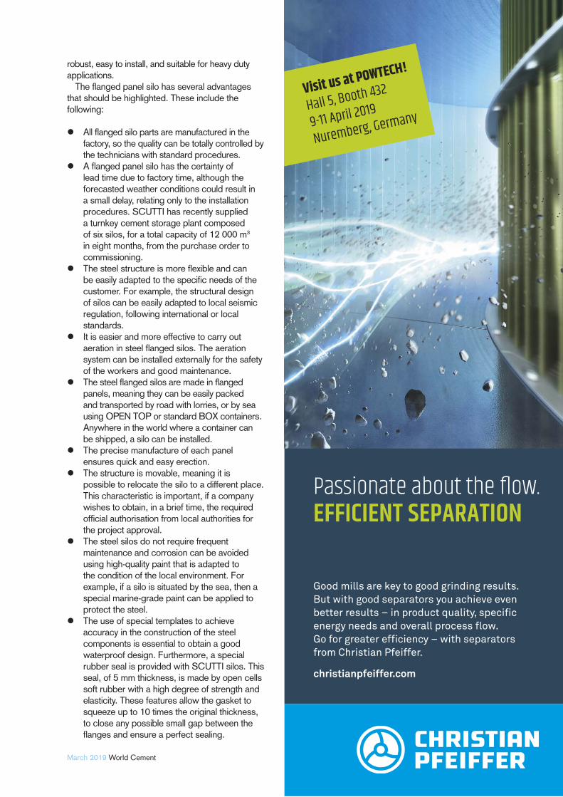
69March 2019 World Cement
robust, easy to install, and suitable for heavy duty applications.
The fl anged panel silo has several advantages that should be highlighted. These include the following:
All fl anged silo parts are manufactured in the factory, so the quality can be totally controlled by the technicians with standard procedures.
A fl anged panel silo has the certainty of lead time due to factory time, although the forecasted weather conditions could result in a small delay, relating only to the installation procedures. SCUTTI has recently supplied a turnkey cement storage plant composed of six silos, for a total capacity of 12 000 m3 in eight months, from the purchase order to commissioning.
The steel structure is more fl exible and can be easily adapted to the specifi c needs of the customer. For example, the structural design of silos can be easily adapted to local seismic regulation, following international or local standards.
It is easier and more effective to carry out aeration in steel fl anged silos. The aeration system can be installed externally for the safety of the workers and good maintenance.
The steel fl anged silos are made in fl anged panels, meaning they can be easily packed and transported by road with lorries, or by sea using OPEN TOP or standard BOX containers. Anywhere in the world where a container can be shipped, a silo can be installed.
The precise manufacture of each panel ensures quick and easy erection.
The structure is movable, meaning it is possible to relocate the silo to a different place. This characteristic is important, if a company wishes to obtain, in a brief time, the required offi cial authorisation from local authorities for the project approval.
The steel silos do not require frequent maintenance and corrosion can be avoided using high-quality paint that is adapted to the condition of the local environment. For example, if a silo is situated by the sea, then a special marine-grade paint can be applied to protect the steel.
The use of special templates to achieve accuracy in the construction of the steel components is essential to obtain a good waterproof design. Furthermore, a special rubber seal is provided with SCUTTI silos. This seal, of 5 mm thickness, is made by open cells soft rubber with a high degree of strength and elasticity. These features allow the gasket to squeeze up to 10 times the original thickness, to close any possible small gap between the fl anges and ensure a perfect sealing.
Visit us at POWTECH!
Hall 5, Booth 432
9-11 April 2019
Nuremberg, Germany
Good mills are key to good grinding results. But with good separators you achieve even better results – in product quality, specific energy needs and overall process flow. Go for greater efficiency – with separators from Christian Pfeiffer.
christianpfeiffer.com
EFFICIENT SEPARATION
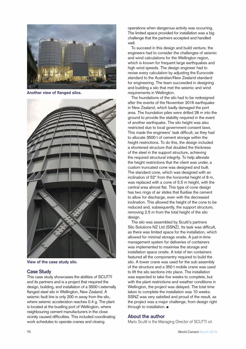
70 World Cement March 2019
Case StudyThis case study showcases the abilities of SCUTTI and its partners and is a project that required the design, building, and installation of a 3500 t externally fl anged steel silo in Wellington, New Zealand. A seismic fault line is only 200 m away from the silo, where seismic acceleration reaches 0.4 g. The plant is located at the bustling port of Wellington, where neighbouring cement manufacturers in the close vicinity caused diffi culties. This included coordinating work schedules to operate cranes and closing
operations when dangerous activity was occurring. The limited space provided for installation was a big challenge that the partners accepted and handled well.
To succeed in this design and build venture, the engineers had to consider the challenges of seismic and wind calculations for the Wellington region, which is known for frequent large earthquakes and high wind speeds. The design engineer had to revise every calculation by adjusting the Eurocode standard to the Australian/New Zealand standard for engineering. The team succeeded in designing and building a silo that met the seismic and wind requirements in Wellington.
The foundations of the silo had to be redesigned after the events of the November 2016 earthquake in New Zealand, which badly damaged the port area. The foundation piles were drilled 28 m into the ground to provide the stability required in the event of another earthquake. The silo height was also restricted due to local government consent laws. This made the engineers’ task diffi cult, as they had to allocate 3500 t of cement storage within the height restrictions. To do this, the design included a shortened structure that doubled the thickness of the steel in the support structure, achieving the required structural integrity. To help alleviate the height restrictions that the client was under, a custom truncated cone was designed and built. The standard cone, which was designed with an inclination of 52° from the horizontal height of 8 m, was replaced with a cone of 5.5 m height, with the central area almost fl at. This type of cone design has two rings of air slides that fl uidise the cement to allow for discharge, even with the decreased inclination. This allowed the height of the cone to be reduced and, subsequently, the support structure, removing 2.5 m from the total height of the silo design.
The silo was assembled by Scutti’s partners Silo Solutions NZ Ltd (SSNZ). Its task was diffi cult, as there was limited space for the installation, which allowed for minimal storage onsite. A just-in-time management system for deliveries of containers was implemented to maximise the storage and installation space onsite. A total of ten containers featured all the componentry required to build the silo. A tower crane was used for the sub assembly of the structure and a 350 t mobile crane was used to lift the silo sections into place. The installation was expected to take fi ve weeks to complete, but with the plant restrictions and weather conditions in Wellington, the project was delayed. The total time taken to complete the installation was 10 weeks. SSNZ was very satisfi ed and proud of the result, as the project was a major challenge, from design right through to installation.
About the authorMario Scutti is the Managing Director of SCUTTI srl.
Another view of fl anged silos.
View of the case study silo.
Brick by
brick
71
Lars Lindgren, Bricking Solutions, investigates how companies can take back lost profits with a bricking
machine.
Having a cement kiln out of commission can cost a plant tens of thousands of dollars in lost production and profi ts each day. When that shutdown is an
emergency repair, as opposed to scheduled maintenance, the costs can grow exponentially. The key to reducing or eliminating unscheduled downtime and minimising the need for scheduled repairs lies in effi cient and quality brick installation. By minimising air gaps and locking rings and loose bricks, the life of kiln lining can be extended and unscheduled or emergency maintenance can be drastically reduced.
While many methods for installation exist and contractors who are experienced with one method or another will swear by their process, the proof is in the result. Contractors who have tried multiple
techniques typically agree that using a bricking machine leads to extensive savings through installation, quality, and safety enhancements.
Time is money The old adage that time is money could not be more true than in the case of a cement plant. Tens of thousands of dollars in lost revenue is each day compounded when the right equipment or refractory material is not onsite and ready for installation work. This illustrates the importance of planned maintenance, rather than emergency repairs.
Bricking machines provide cement plants with a way to speed up the refractory installation process, saving thousands of dollars in labour costs. Many factors affect brick installation,
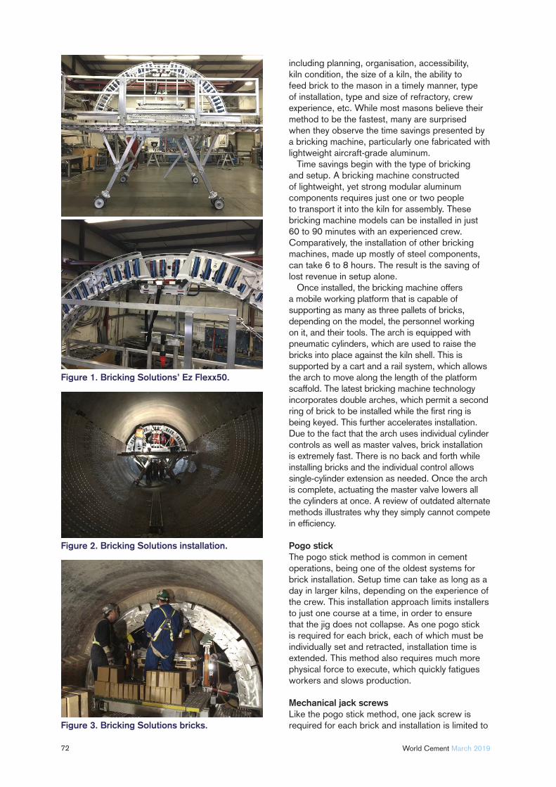
72 World Cement March 2019
including planning, organisation, accessibility, kiln condition, the size of a kiln, the ability to feed brick to the mason in a timely manner, type of installation, type and size of refractory, crew experience, etc. While most masons believe their method to be the fastest, many are surprised when they observe the time savings presented by a bricking machine, particularly one fabricated with lightweight aircraft-grade aluminum.
Time savings begin with the type of bricking and setup. A bricking machine constructed of lightweight, yet strong modular aluminum components requires just one or two people to transport it into the kiln for assembly. These bricking machine models can be installed in just 60 to 90 minutes with an experienced crew. Comparatively, the installation of other bricking machines, made up mostly of steel components, can take 6 to 8 hours. The result is the saving of lost revenue in setup alone.
Once installed, the bricking machine offers a mobile working platform that is capable of supporting as many as three pallets of bricks, depending on the model, the personnel working on it, and their tools. The arch is equipped with pneumatic cylinders, which are used to raise the bricks into place against the kiln shell. This is supported by a cart and a rail system, which allows the arch to move along the length of the platform scaffold. The latest bricking machine technology incorporates double arches, which permit a second ring of brick to be installed while the fi rst ring is being keyed. This further accelerates installation. Due to the fact that the arch uses individual cylinder controls as well as master valves, brick installation is extremely fast. There is no back and forth while installing bricks and the individual control allows single-cylinder extension as needed. Once the arch is complete, actuating the master valve lowers all the cylinders at once. A review of outdated alternate methods illustrates why they simply cannot compete in effi ciency.
Pogo stickThe pogo stick method is common in cement operations, being one of the oldest systems for brick installation. Setup time can take as long as a day in larger kilns, depending on the experience of the crew. This installation approach limits installers to just one course at a time, in order to ensure that the jig does not collapse. As one pogo stick is required for each brick, each of which must be individually set and retracted, installation time is extended. This method also requires much more physical force to execute, which quickly fatigues workers and slows production.
Mechanical jack screws Like the pogo stick method, one jack screw is required for each brick and installation is limited to
Figure 1. Bricking Solutions’ Ez Flexx50.
Figure 2. Bricking Solutions installation.
Figure 3. Bricking Solutions bricks.
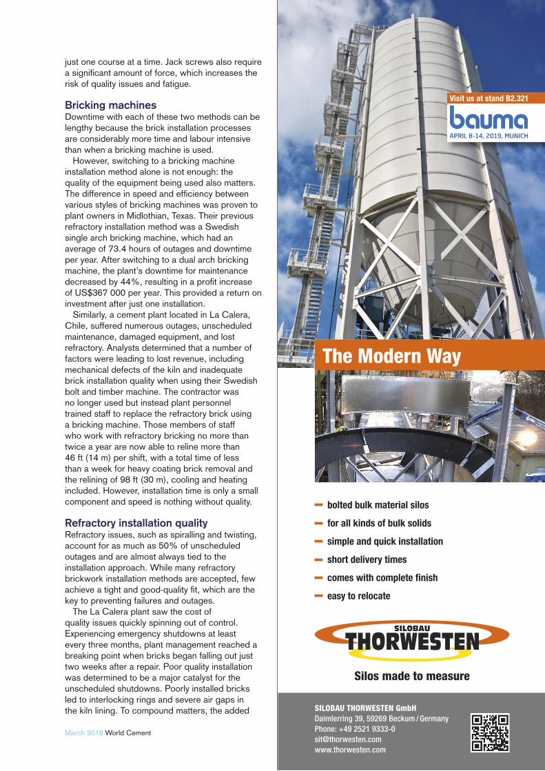
73March 2019 World Cement
just one course at a time. Jack screws also require a signifi cant amount of force, which increases the risk of quality issues and fatigue.
Bricking machinesDowntime with each of these two methods can be lengthy because the brick installation processes are considerably more time and labour intensive than when a bricking machine is used.
However, switching to a bricking machine installation method alone is not enough: the quality of the equipment being used also matters. The difference in speed and effi ciency between various styles of bricking machines was proven to plant owners in Midlothian, Texas. Their previous refractory installation method was a Swedish single arch bricking machine, which had an average of 73.4 hours of outages and downtime per year. After switching to a dual arch bricking machine, the plant’s downtime for maintenance decreased by 44%, resulting in a profi t increase of US$367 000 per year. This provided a return on investment after just one installation.
Similarly, a cement plant located in La Calera, Chile, suffered numerous outages, unscheduled maintenance, damaged equipment, and lost refractory. Analysts determined that a number of factors were leading to lost revenue, including mechanical defects of the kiln and inadequate brick installation quality when using their Swedish bolt and timber machine. The contractor was no longer used but instead plant personnel trained staff to replace the refractory brick using a bricking machine. Those members of staff who work with refractory bricking no more than twice a year are now able to reline more than 46 ft (14 m) per shift, with a total time of less than a week for heavy coating brick removal and the relining of 98 ft (30 m), cooling and heating included. However, installation time is only a small component and speed is nothing without quality.
Refractory installation quality Refractory issues, such as spiralling and twisting, account for as much as 50% of unscheduled outages and are almost always tied to the installation approach. While many refractory brickwork installation methods are accepted, few achieve a tight and good-quality fi t, which are the key to preventing failures and outages.
The La Calera plant saw the cost of quality issues quickly spinning out of control. Experiencing emergency shutdowns at least every three months, plant management reached a breaking point when bricks began falling out just two weeks after a repair. Poor quality installation was determined to be a major catalyst for the unscheduled shutdowns. Poorly installed bricks led to interlocking rings and severe air gaps in the kiln lining. To compound matters, the added
Silos made to measure
bolted bulk material silos
for all kinds of bulk solids
simple and quick installation
short delivery times
comes with complete fi nish
easy to relocate
The Modern Way
SILOBAU THORWESTEN GmbHDaimlerring 39, 59269 Beckum / GermanyPhone: +49 2521 [email protected]
Visit us at stand B2.321
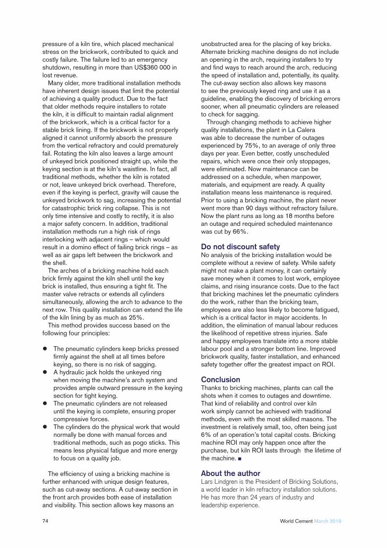
74 World Cement March 2019
pressure of a kiln tire, which placed mechanical stress on the brickwork, contributed to quick and costly failure. The failure led to an emergency shutdown, resulting in more than US$360 000 in lost revenue.
Many older, more traditional installation methods have inherent design issues that limit the potential of achieving a quality product. Due to the fact that older methods require installers to rotate the kiln, it is diffi cult to maintain radial alignment of the brickwork, which is a critical factor for a stable brick lining. If the brickwork is not properly aligned it cannot uniformly absorb the pressure from the vertical refractory and could prematurely fail. Rotating the kiln also leaves a large amount of unkeyed brick positioned straight up, while the keying section is at the kiln’s waistline. In fact, all traditional methods, whether the kiln is rotated or not, leave unkeyed brick overhead. Therefore, even if the keying is perfect, gravity will cause the unkeyed brickwork to sag, increasing the potential for catastrophic brick ring collapse. This is not only time intensive and costly to rectify, it is also a major safety concern. In addition, traditional installation methods run a high risk of rings interlocking with adjacent rings – which would result in a domino effect of failing brick rings – as well as air gaps left between the brickwork and the shell.
The arches of a bricking machine hold each brick fi rmly against the kiln shell until the key brick is installed, thus ensuring a tight fi t. The master valve retracts or extends all cylinders simultaneously, allowing the arch to advance to the next row. This quality installation can extend the life of the kiln lining by as much as 25%.
This method provides success based on the following four principles:
The pneumatic cylinders keep bricks pressed fi rmly against the shell at all times before keying, so there is no risk of sagging.
A hydraulic jack holds the unkeyed ring when moving the machine’s arch system and provides ample outward pressure in the keying section for tight keying.
The pneumatic cylinders are not released until the keying is complete, ensuring proper compressive forces.
The cylinders do the physical work that would normally be done with manual forces and traditional methods, such as pogo sticks. This means less physical fatigue and more energy to focus on a quality job.
The effi ciency of using a bricking machine is further enhanced with unique design features, such as cut-away sections. A cut-away section in the front arch provides both ease of installation and visibility. This section allows key masons an
unobstructed area for the placing of key bricks. Alternate bricking machine designs do not include an opening in the arch, requiring installers to try and fi nd ways to reach around the arch, reducing the speed of installation and, potentially, its quality. The cut-away section also allows key masons to see the previously keyed ring and use it as a guideline, enabling the discovery of bricking errors sooner, when all pneumatic cylinders are released to check for sagging.
Through changing methods to achieve higher quality installations, the plant in La Calera was able to decrease the number of outages experienced by 75%, to an average of only three days per year. Even better, costly unscheduled repairs, which were once their only stoppages, were eliminated. Now maintenance can be addressed on a schedule, when manpower, materials, and equipment are ready. A quality installation means less maintenance is required. Prior to using a bricking machine, the plant never went more than 90 days without refractory failure. Now the plant runs as long as 18 months before an outage and required scheduled maintenance was cut by 66%.
Do not discount safetyNo analysis of the bricking installation would be complete without a review of safety. While safety might not make a plant money, it can certainly save money when it comes to lost work, employee claims, and rising insurance costs. Due to the fact that bricking machines let the pneumatic cylinders do the work, rather than the bricking team, employees are also less likely to become fatigued, which is a critical factor in major accidents. In addition, the elimination of manual labour reduces the likelihood of repetitive stress injuries. Safe and happy employees translate into a more stable labour pool and a stronger bottom line. Improved brickwork quality, faster installation, and enhanced safety together offer the greatest impact on ROI.
ConclusionThanks to bricking machines, plants can call the shots when it comes to outages and downtime. That kind of reliability and control over kiln work simply cannot be achieved with traditional methods, even with the most skilled masons. The investment is relatively small, too, often being just 6% of an operation’s total capital costs. Bricking machine ROI may only happen once after the purchase, but kiln ROI lasts through the lifetime of the machine.
About the authorLars Lindgren is the President of Bricking Solutions, a world leader in kiln refractory installation solutions. He has more than 24 years of industry and leadership experience.
World-Leading Trade Fair for Processing, Analysis, and Handling of Powder and Bulk Solids
Honorary sponsors Together with
First comes the experience, then the success: discover the entire spectrum and dynamic energy of mechanical process engineering. POWTECH is the trade fair event for bulk solids – and the place where process optimisation begins.
Professional knowledge right from the experts and contacts that will help you move ahead: The supporting programme will make your trade fair visit even more worthwhile with the following highlights:• Expert Forums for Chemistry and Food • Pharma.Manufacturing.Excellence. Forum• Networking Campus• Special display area for explosion protection • VDMA Special Show: Dust knows no borders
EXPERIENCE THE DYNAMIC ENERGY, SHARE KNOWLEDGE,OPTIMISE PROCESSES
9-11.4.2019NUREMBERG, GERMANY
Contact our Flue Gas Treatment Experts
Sorbacal® - Acid Gas and Mercury Sorbentsflexible, reliable, and cost
effective
High surface area, pore volume, and optimal particle sizing
Simultaneous Hg and acid gas abatement
Lhoist makes it easy to evaluate sorbents
Sorbacal® Sorbents: Your Solution to Acid Gas and Hg Pollution

JOIN US IN
REGISTRATION NOW OPEN
St Louis, Missouri28th April - 2nd Maywww.cementconference.org
2019

77
Chained
MelodyWorld Cement rounds up the latest news and views from the chain sector.
While new technologies in the cement and mining sectors may not be as profound or as frequent as in other industries, quarry and
mine operators are focused on the continuous improvement of processes and equipment to achieve greater capacity and improved reliability, writes Dane Olsen of BEUMER Corp.
78 World Cement March 2019
In industries that have invested very little in equipment upgrades since the economic downturn of 2008 and 2009, the modernisation of existing systems to increase throughput is a focal point, as market demand continues to rebound in sectors such as cement.
The most common retrofi ts are occurring with bucket elevators and apron conveyors, where metal chain traction elements are still being utilised in conveying. For many years, conditions related to particle size or temperature required the use of only chains in both bucket elevators and apron conveyors. Notoriously expensive to maintain and replace, chains require continuous monitoring and must be shortened as they stretch.
Knowing that anything mechanical begins wearing down as soon as it begins to operate, full system optimisation declines over time. A proprietary steel cable belting solution engineered by BEUMER to replace chain traction elements can help systems achieve what they did when they were fi rst installed.
A steel cable reinforced belt requires a fraction of the maintenance of a chain and delivers a lifespan of three to four times. With apron conveyors, for example, belt alternative modernisations have inherent benefi ts that include the following:
Reduction of the constant maintenance required by chain wear. With a belt, you install it, attach the buckets or pans, tighten everything down into the splice, then only need to perform routine maintenance, with in-depth checks, once or twice a year. Thus,
the need to stop the machine for extended periods of time, while chain stretch is measured, sprockets are replaced, and pans are removed, is eliminated.
Improvement of the ambient working environment. The smooth transition of a belt/pulley traction element reduces the noise caused by a chain/sprocket element.
Considerably longer wear life. Belts reinforced with steel wires are at the centre of a proprietary design that ensures a long service life of three to four times that of a chain.
Improved safety by reducing maintenance touchpoints. The shortening process for heavy chains that often operate above grade, sometimes signifi cantly so, presents safety concerns for maintenance staff.
Belt modernisation capabilities are effective in a variety of industries, such as cement, lime, and gypsum, where bucket elevators and apron conveyors are used for transport, as well as in industrial processes and where roasters are in use, such as gold, precious metals, and iron ore.
About the authorDane Olson joined BEUMER Corp. in 2016 and serves
as Customer Support Manager for the company’s
Conveying and Loading (CL) division in Kansas City,
Missouri, US. He is responsible for business
development, sales support, and service planning
for CL systems and products. Olson is a graduate of
the University of Central Oklahoma with a degree in
corporate/organisational communication.
The art of chain designIndustry has many choices today for conveyor chains, writes AUMUND Group. Most available chains are designed for a certain strength rating and expected wear life. However, there is much more to chain design than these basic parameters. AUMUND has designed its chains to meet the demand of certain heavy production industries, based on more than 40 years of experience, with over 18 000 machinery references in more than 140 countries.
The chains used for those industries not only meet the strength and wear requirements, but years of refi nements to the design also address the unique requirements of a large ball mill circuit bucket elevator or high-capacity steep pan conveyor. AUMUND chains consider a wear life based upon actual pin/bushing pressures and the material conveyed, not just
the thickness of the wear treatment on a pin or bushing. The strength rating also considers the fatigue requirements in specifi c and well-experienced applications.
These considerations have not only resulted in the best technology for the chain product line, as designed, but also in the thorough knowledge required to make the best selection from such an extensive chain product line, which is equally important. Many suppliers cannot offer this support and advice.
AUMUND has more heavy-duty, highly-rated chains in operation than any other supplier. Such experience takes the company beyond pure metallurgy and mechanics for chain design and application. There is an art, as well as a science, to the design and application of critical heavy duty chains for the industries AUMUND serves.
AD INDEXAD INDEX21
13
IFC
41
47
04
IBC
55
69
31
63
59
09
15
OFC, 02
76
33
4B Components Ltdwww.go4b.com/usa
Agudiowww.agudio.com
SCHADE Lagertechnik GmbHwww.schade-lagertechnik.com
Beumer Groupwww.beumergroup.com
CemCatwww.cemcat.com
Christian Pfeifferwww.christianpfeiffer.com
Cintasawww.cintasa.com
DISAB Vaccum Technologywww.disab.com
Dunlop Conveyor Beltingwww.dunlopcb.com
FLSmidthwww.fl smidth.com
GEDAwww.bauma-geda.de
HEKO Groupwww.heko.com
IEEE-IAS/PCA Cement Industry Conference 2019www.cementconference.org
KettenWulfwww.kettenwulf.com
KIMA Process Controlwww.kima-process.de
Muller Beltexwww.mullerbeltex.com
29
25
75
37
39
75
34
39
53
07
34
31
73
OBC
45
37
17
Peter und Lochnerwww.pul-ingenieure.de
POWTECHwww.powtech.de
SIGwww.sig.it
Scantechwww.scantech.com.au
Silobau Thorwestenwww.thorwesten.com
Standard Industrie Internationalwww.standard-industrie.com
Tank Connectionwww.tankconnection.com
Thorwesten Vent GmbHwww.thorwesten.com
Scheuch www.scheuch.com
Bosch Rexrothwww.boschrexroth.com
CEMTECwww.cemtec.at
Lhoistwww.lhoist.com
REMBE GmbHwww.rembe.com
International Cement Business Conferencewww.white-nights.info
Boldrocchiwww.boldrocchigroup.com
Siliconwww.silicon.nu
SN Engineeringwww.sneng.co.uk
Axianswww.axians-ias.com

5 MINUTES5 MINUTES
80 World Cement March 2019
Briefl y describe your job.I am an independent consultant specialising in the deployment
of strategies and roadmaps to address crucial sustainability issues, namely climate change, circular economy, and biodiversity. One of my key current assignments is the coordination of the climate programme of the World Cement Association (WCA).
How did you start in the cement industry?In 1996, as young chemical engineer, I started to work for CBR, the Belgian subsidiary of HeidelbergCement, where I was recruited as technical advisor, supporting the CBR customers in the use of cement and binders for environmental purposes. One of my fi rst projects was also to fi nd valuable solutions for bypass kiln dust from one of the clinker kilns. I then worked successively for HeidelbergCement, Holcim, and LafargeHolcim as global Head of Sustainable Development.
What is your proudest career achievement?I am extremely proud of the positive energy, commitment and enthusiasm that resulted from the development of the fi rst sustainability roadmaps of HeidelbergCement (in 2008) and LafargeHolcim (in 2016), which I both coordinated. It was fantastic to see the engagement of all members of the respective sustainability teams and of so many employees, from subsidiaries around the globe, who actively wanted to contribute and deliver value for business, for society, and for our planet. It was a privilege for me to witness the very particular importance of social responsibility issues for our workers and employees: this helped me build a sense of purpose in my day-to-day work.
In your view, what is the biggest challenge facing the cement industry?You will not be surprised if I insist on the crucial issue of the required transition towards a low-carbon construction sector. I am convinced that our sector will be increasingly challenged by regulators, civil society, and other stakeholders about its impacts on climate
and its commitment to drastically reduce greenhouse gas emissions over the lifecycle of buildings and infrastructure. This is an existential challenge for the industry, which also opens massive opportunities for innovation, creativity, and business success.
What strategies can the industry employ to solve this challenge?The global deployment of waste coprocessing is an example. But an enhanced use of existing and new clinker substitutes, considerable improvement of material effi ciency (through a better use of our products), innovation towards new types of clinker, cement, binders and concrete, and the development of projects around carbon capture and storage or carbon capture and utilisation, are all part of the solution. Tailored strategies should be developed by each company depending on its local context.
What do you see your role is in supporting the industry to meet this challenge?As Director of the WCA’s Climate Programme, my role is to raise awareness among WCA members and to provide them with a platform to exchange knowledge about the latest technologies and regulatory developments. The WCA is also acting as a global voice of the industry towards global stakeholders.
What are you reading at the moment?I am passionate about politics and very concerned about the ongoing rise of populism, intolerance, and nationalism across the globe. I am currently enjoying Yuval Harari’s latest book, 21 Lessons for the 21st Century, which provides food for thought on how to possibly reverse these dangerous evolutions.
Do you have a fi nal message for the industry?I know this industry very well and the commitment of its employees to deliver solutions that enhance the quality of life of local communities all around the globe. The climate challenge adds another dimension to this mission: our industry must today aim at providing the building materials for a comfortable life… on a sustainably liveable planet. I am convinced that we will succeed by leveraging the creativity and entrepreneurship of our teams.
Bernard MathieuClimate Programme Director, World Cement Association
leading-edge SCR catalystsfor the cement industry
CemCat creates flexible SCR systems that are adaptable to any process condition in any new or existing cement plant. For clean air: www.cemcat.com
Cem
Cat
- a
busi
ness
uni
t of M
aerz
Ofe
nbau
AG
, Ric
hard
Wag
ner-
Stra
sse
28, 8
027
Zuric
h, S
witz
erla
nd
FOR FURTHER INFORMATION, CALL OR EE-EEEEEEE-MAIL FOR
+44 1452 725210
Dry Bulk Materials Handling, Equipment Design &
Supply Specialists . . . BULK STORAGEGE SILOS & STORESESES
MIXING & & BLENDINGNGNG
SCREWW CONVEYINGNGN
PLANT & PROCESS DESIGN
PNEUMATICIC CONVEYINGNGNNG
--MAIMM IL
SN Engineering, Unit 10 Brunel Court, Waterwells Business Park, Gloucester GL2 2AL UK GL2 2AL UK
DUST CONTROLOL & FILTRATIONONONN
LOADING G BELLOWSWSWWS
ISOLATION & FLOWW CONTROL VALVESESESS
Related Documents