Height Modernization National and Kentucky Programs 2007 KAPS Conference Bowling Green, Kentucky February 16, 2007 Ross Mackay Kentucky Geodetic Advisor

Height Modernization National and Kentucky Programs 2007 KAPS Conference Bowling Green, Kentucky February 16, 2007 Ross Mackay Kentucky Geodetic Advisor.
Dec 16, 2015
Welcome message from author
This document is posted to help you gain knowledge. Please leave a comment to let me know what you think about it! Share it to your friends and learn new things together.
Transcript
Height ModernizationNational and Kentucky Programs
2007 KAPS ConferenceBowling Green, Kentucky
February 16, 2007
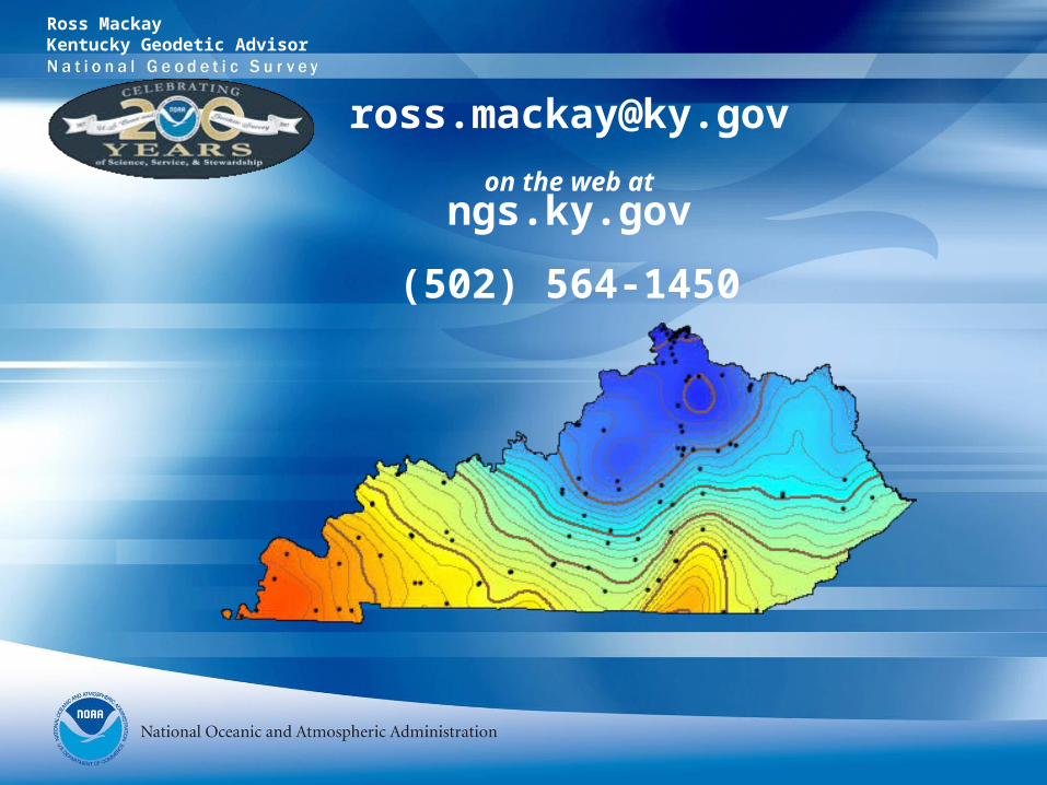
Ross MackayKentucky Geodetic Advisor

Elevation and the Geoid
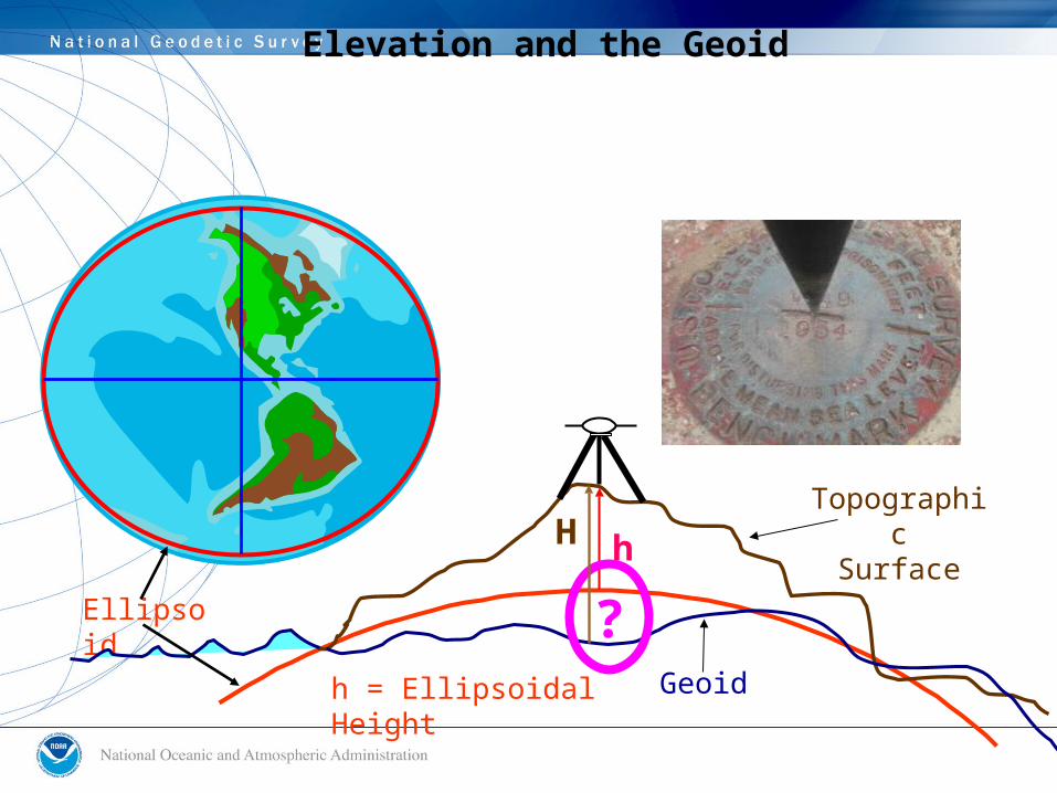
h
TopographicSurface
h = Ellipsoidal Height
Elevation and the Geoid
Ellipsoid
Geoid
?
H

H h
Ellipsoid
H = Elevation (Orthometric Height)
N
Geoid
Topographic
Surface
h = Ellipsoidal Height (from GPS)
N = Geoid Height (from Geoid model)
= h - NNH h
Elevation and the Geoid

Hybrid geoid model
• Gravity
• Leveling
• GPS
• best fit to NAVD 88
Elevation and the Geoid
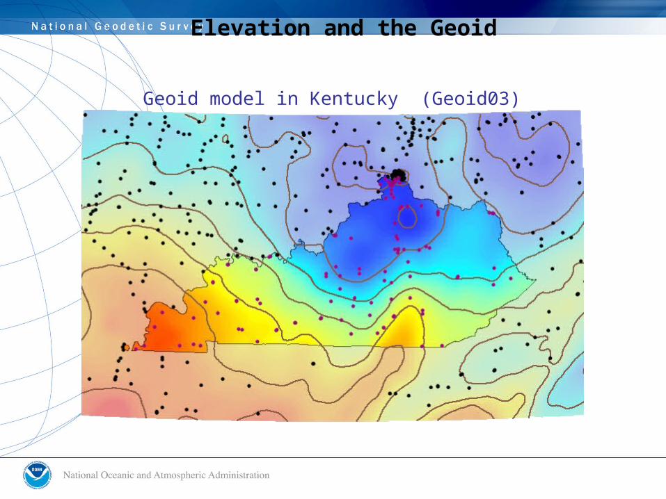
Geoid model in Kentucky (Geoid03)
Elevation and the Geoid


Morehead State University
• Grant recipient from NOAA• Submit application and project reports for Grant• Develop Kentucky CORS Data Archive Center
KY Division of Geographic Information
• Provide overall Height Modernization project management
• Develop project charters, plans and agreements
Kentucky Transportation Cabinet
• Install and provide ongoing support of CORS sites
• Manage the award of contracts and oversight of the work
Kentucky Height Modernization
Kentucky Height Modernization

Kentucky Height Modernization
Site Visits
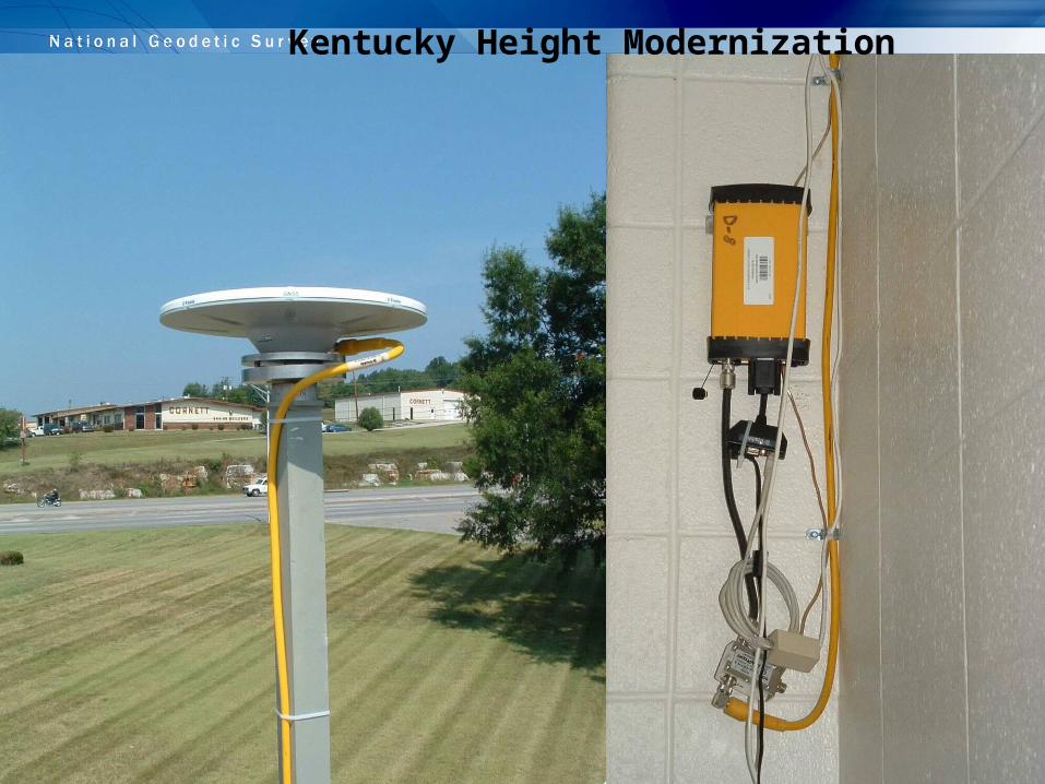
CORS Installation Requirements
• Stable site with minimal obstructions
• Uninterrupted Power Supply
• Internet Connection
• Secure Area

Delivery: May 16, 2006
Kentucky Height Modernization

Kentucky Height Modernization

Kentucky Height Modernization

Kentucky Height Modernization

Kentucky Height Modernization

Kentucky Height Modernization

Kentucky Height Modernization

Kentucky Height Modernization

KYTC & COT Partners
Kentucky Height Modernization
Perry Semones Larry Britton
Danielle Buchanan
Benefits of Height Mod For KYTC
• $2500 - $3000 Saved per Project for Horizontal Control
• $10,000 - $12,000 Saved per Project for Vertical Control
• An average of 50 projects per year yields a savings of $625,000 – ~25% above the Height Mod investment for one year.
• Highway Districts also benefit by having a permanent CORS - savings gained from reduced equipment costs.
Kentucky Height Modernization

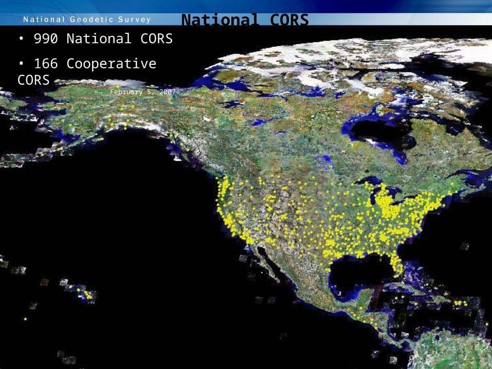
• 990 National CORS
• 166 Cooperative CORSFebruary 5, 2007
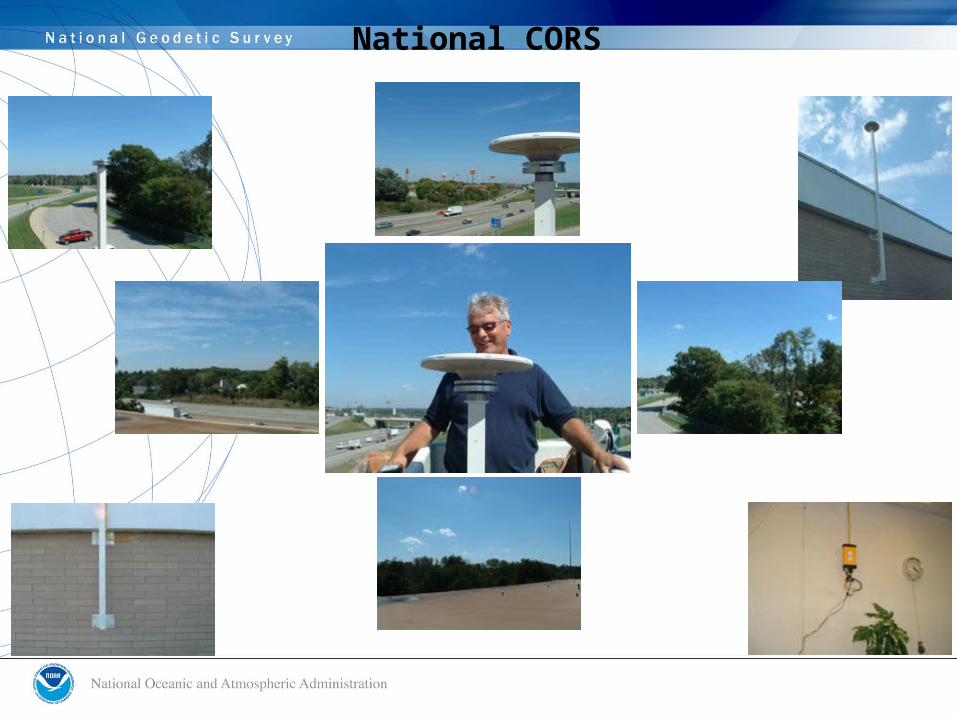
National CORS

National CORS
“These look like some of the best CORS sites that I've seen.” – Don Haw, NGS CORS team member
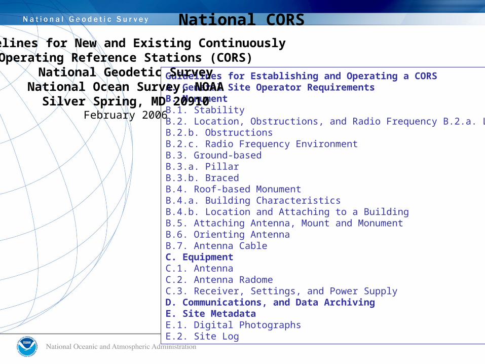
Guidelines for Establishing and Operating a CORS A. General Site Operator Requirements B. MonumentB.1. StabilityB.2. Location, Obstructions, and Radio Frequency B.2.a. LocationB.2.b. ObstructionsB.2.c. Radio Frequency EnvironmentB.3. Ground-basedB.3.a. PillarB.3.b. Braced B.4. Roof-based Monument B.4.a. Building CharacteristicsB.4.b. Location and Attaching to a BuildingB.5. Attaching Antenna, Mount and MonumentB.6. Orienting AntennaB.7. Antenna CableC. EquipmentC.1. AntennaC.2. Antenna RadomeC.3. Receiver, Settings, and Power SupplyD. Communications, and Data ArchivingE. Site MetadataE.1. Digital PhotographsE.2. Site Log
Guidelines for New and Existing ContinuouslyOperating Reference Stations (CORS)
National Geodetic SurveyNational Ocean Survey, NOAA
Silver Spring, MD 20910February 2006
National CORS

National CORS KYTG Site Information Form (site log) NGS CORS See Instructions at: http://www.ngs.noaa.gov/PUBS_LIB/CORS_guidelines.pdf
0. Form Prepared by (full name) : DANIELLE BUCHANAN Date Prepared : 2006-08-30 Report Type : NEW1. Site Identification of the GNSS Monument Site Name : KYTC HIGHWAY DISTRICT 7 Four Character ID : KYTG Monument Description : ALUMINUM BRACKET ON MASONRY WALL Height of the Monument : 10 M.(APPROX.)ABOVE GROUND Monument Foundation : MASSIVE BUILDING FOUNDATION Marker Description : SCIGN adaptor Date Installed : 2006-05-31 Geologic Characteristic : TANGLEWOOD LIMESTONE MEMBER Bedrock Type : LIMESTONE WITH MINOR SHALE INTERBEDS Fault zones nearby : LEXINGTON FAULT SYSTEM Distance/activity : 15,000 FT SE / INACTIVE Additional Information : QUARRIES/MINES: VULCAN LIMESTONE MINE, 11,000 FT SW
GEOLOGIC INFORMATION PROVIDED BY DR. JERRY WEISENFLUH, KGS 2. Site Location Information City or Town : LEXINGTON State or Province : KENTUCKY Country : USA Tectonic Plate : NORTH AMERICA Latitude (N is +) : +380431.96 Longitude (E is +) : -0842931.91 Elevation (m,ellips.) : 265.1 Additional Information : (multiple lines)3. GNSS Receiver Information3.1 Receiver Type : TRIMBLE NETR5 Satellite System : GPS+GLONASS Serial Number : 4618K01153 Firmware Version : 3.10 Elevation Cutoff Setting : 10 Date Installed : 2006-05-314. GNSS Antenna Information4.1 Antenna Type : TRM55971.00 Serial Number : 30137283 Antenna Reference Point : BAM Marker->ARP Up Ecc. (m) : TO BE DETERMINED Marker->ARP North Ecc(m) : 000.0000 Marker->ARP East Ecc(m) : 000.0000 Alignment from True N : -0.0833 deg Antenna Cable Type : TRIMBLE 41300-30 REVA DCA 0610 Antenna Cable Length : 30 M Date Installed : 2006-05-11
Site Log File
National CORS


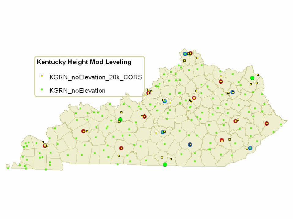
KY Height Mod Pilot Region
Kentucky Height Mod: What’s next?
Last Year’s Model…

Kentucky Height Mod: What’s next?

Leveling to KGRN and CORS
H = h - N
Kentucky Height Mod: What’s next?

Kentucky Height Mod: What’s next?
Kentucky Height Mod: What’s next?


National Readjustment, NAD83(NSRS2007)

NAD83(NSRS2007)
• Only GPS has been adjusted. • The CORS stations served as control, CORS(2002)• Network and local accuracies have been implemented• Datasheets not yet available.• Both NAD 83 and ITRF coordinates will be produced and
published.
• Data available in Readjustment Distribution Format (RDF)
National Readjustment, NAD83(NSRS2007)

*A1* *10*ky.bfile *13*NAD 83(NSRS 2007) HZ2483*80*0001PISGAH 2 RESET 38025475240N084391492065W KY HZ2483*86*0001 256104 GZ1222*80*0002M 154 RESET 37592167847N084315027428W KY GZ1222*86*0002 276428 GZ2558*80*0003ROBB RESET 37563532212N084331236840W KY GZ2558*86*0003 285372 GZ3070*80*0004LFUCG GPS STA 0029 37563416073N084295602129W KY GZ3070*86*0004 250922 HZ1856*80*0005A 145 RESET 38024283402N084342106297W KY HZ1856*86*0005 260146 GZ2896*80*0006COMBS 37533423194N084171921273W KY GZ2896*86*0006 271861 GZ3069*80*0007LFUCG GPS STA 0001 37525876824N084235309452W KY GZ3069*86*0007 261925 HZ1984*80*0008GEORGETOWN RESET 38115683816N084323111820W KY HZ1984*86*0008 249376 GZ3094*80*0009LFUCG GPS STA 0070 37570999009N084272018803W KY GZ3094*86*0009 262872 GZ3087*80*0010LFUCG GPS STA 0063 37575701433N084280020821W KY GZ3087*86*0010 270100 HZ0162*80*0011I75 T 78 AZ MK 38021283676N084240349241W KY HZ0162*86*0011 273295 GZ3074*80*0012LFUCG GPS STA 0050 37592673348N084260134752W KY GZ3074*86*0012 265311 GZ3086*80*0013LFUCG GPS STA 0062 37583525771N084275187363W KY GZ3086*86*0013 280485 GZ3077*80*0014LFUCG GPS STA 0053 37592735030N084294281391W KY GZ3077*86*0014 259798
National Readjustment, NAD83(NSRS2007)


• To define, maintain and provide access to the NationalSpatial Reference System to meet our nation’s economic,social, and environmental needs
and
• To be a world leader in geospatial activities, including thedevelopment and promotion of standards, specifications, and guidelines.
Mission of NGS
• FY07 NGS Annual Guidance Document• NGS 10 Year Plan• FY07 NGS Execution Plan• Improve Communication with NGS Stakeholders
Planning Procedure
Planning at NGS
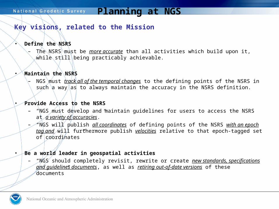
Key visions, related to the Mission
• Define the NSRS– The NSRS must be more accurate than all activities which build upon it, while still
being practicably achievable.
• Maintain the NSRS– NGS must track all of the temporal changes to the defining points of the NSRS in
such a way as to always maintain the accuracy in the NSRS definition.
• Provide Access to the NSRS– “NGS must develop and maintain guidelines for users to access the NSRS at a
variety of accuracies.”– “NGS will publish all coordinates of defining points of the NSRS with an epoch tag
and will furthermore publish velocities relative to that epoch-tagged set of coordinates”
• Be a world leader in geospatial activities– “NGS should completely revisit, rewrite or create new standards, specifications
and guidelines documents, as well as retiring out-of-date versions of these documents”
Planning at NGS

In order to achieve the vision,these areas of emphasis must drive all future NGS activities
– Modernize CORS(NGS owned and operated Foundation CORS?)
– Improve gravity field modeling(Define North American vertical datum through GNSS and a gravimetric geoid?)
– Migrate the coastal mapping program toward IOCM(Fully integrate NGS shoreline activities with other NOAA coastal mapping)
– Add and improve core capabilities(Retrain and retool NGS workforce, Modernize tools)
– Implement a global leadership strategy(Standards & specifications, educational initiatives, increased publication)
Planning at NGS
Related Documents


![KAPS-14 Kod Amalan Anugerah Akademik Pengajian …sps.utm.my/.../KAPS-14-Kod-Amalan-Anugerah-Akademik-Pengajian-… · kod amalan hadiah akademik pengajian siswazah] kaps-14 sekolah](https://static.cupdf.com/doc/110x72/5b8a5f767f8b9aa81a8e6586/kaps-14-kod-amalan-anugerah-akademik-pengajian-spsutmmykaps-14-kod-amalan-anugerah-akademik-pengajian-.jpg)