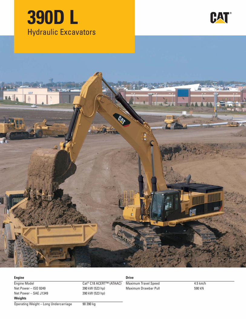
390D L Hydraulic Excavators Engine Engine Model Cat ® C18 ACERT™ (ATAAC) Net Power – ISO 9249 390 kW (523 hp) Net Power – SAE J1349 390 kW (523 hp) Weights Operating Weight – Long Undercarriage 90 390 kg Drive Maximum Travel Speed 4.5 km/h Maximum Drawbar Pull 590 kN

Welcome message from author
This document is posted to help you gain knowledge. Please leave a comment to let me know what you think about it! Share it to your friends and learn new things together.
Transcript
390D LHydraulic Excavators
Engine
Engine Model Cat® C18 ACERT™ (ATAAC)
Net Power – ISO 9249 390 kW (523 hp)
Net Power – SAE J1349 390 kW (523 hp)
Weights
Operating Weight – Long Undercarriage 90 390 kg
Drive
Maximum Travel Speed 4.5 km/h
Maximum Drawbar Pull 590 kN

2
The Cat® 390D L Hydraulic Excavator has excellent control, high stick and bucket forces, simplifi ed service and a comfortable operator station to increase your productivity and lower operating costs.
Features
PerformanceHigh level of sustained production, improved performance, reliability and durability increase your productivity and lower your operating costs.
EngineThe Cat® C18 engine uses ACERT™ Technology to meet Stage IIIA emission regulations with exceptional performance capabilities and proven reliability.
Operator StationSuperior cab comfort and visibility provide an excellent working environment. The full-color monitor with graphic display features enhanced functionality to provide a simple, comprehensive machine interface.
Maximum VersatilityA variety of work tools, including buckets, are available for applications such as demolition, site clean-up, scrap processing, breaking up road surfaces and bedrock through Cat® Work Tools.
Service and MaintenanceFast, easy service has been designed in with long service intervals, advanced fi ltration, convenient fi lter access and user-friendly electronic diagnostics for increased productivity and reduced maintenance costs.
ContentsHydraulics ............................................................3
Operator Station ..................................................4
Engine ...................................................................5
Control System ....................................................6
Structures.............................................................7
Undercarriage .....................................................8
Front Linkage .......................................................9
SmartBoom™ .....................................................10
Buckets and Teeth ............................................11
Work Tools ..........................................................12
Environment .......................................................13
Service and Maintenance ...............................14
Complete Customer Support ...........................15
390D L Hydraulic ExcavatorSpecifi cations ....................................................16
390D L Standard Equipment ............................32
390D L Optional Equipment ..............................33
Notes ...................................................................34
3
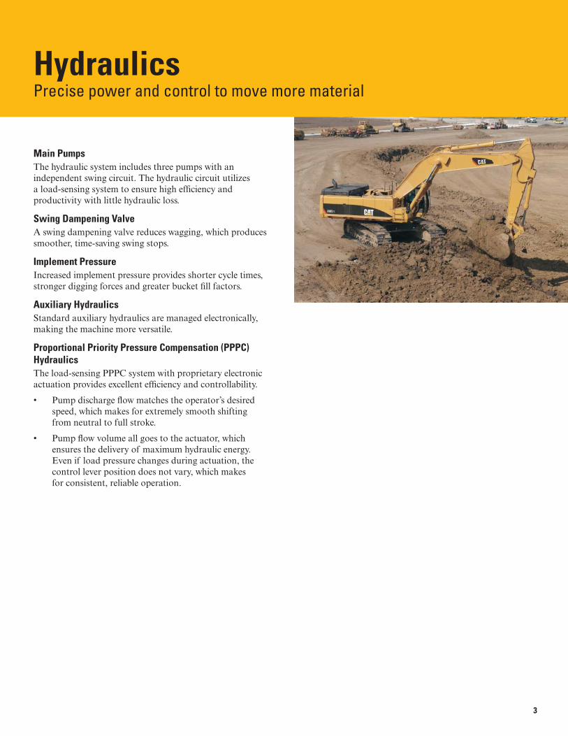
HydraulicsPrecise power and control to move more material
Main PumpsThe hydraulic system includes three pumps with an independent swing circuit. The hydraulic circuit utilizes a load-sensing system to ensure high effi ciency and productivity with little hydraulic loss.
Swing Dampening ValveA swing dampening valve reduces wagging, which produces smoother, time-saving swing stops.
Implement PressureIncreased implement pressure provides shorter cycle times, stronger digging forces and greater bucket fi ll factors.
Auxiliary HydraulicsStandard auxiliary hydraulics are managed electronically, making the machine more versatile.
Proportional Priority Pressure Compensation (PPPC) HydraulicsThe load-sensing PPPC system with proprietary electronic actuation provides excellent effi ciency and controllability.
• Pump discharge fl ow matches the operator’s desired speed, which makes for extremely smooth shifting from neutral to full stroke.
• Pump fl ow volume all goes to the actuator, which ensures the delivery of maximum hydraulic energy. Even if load pressure changes during actuation, the control lever position does not vary, which makes for consistent, reliable operation.
4
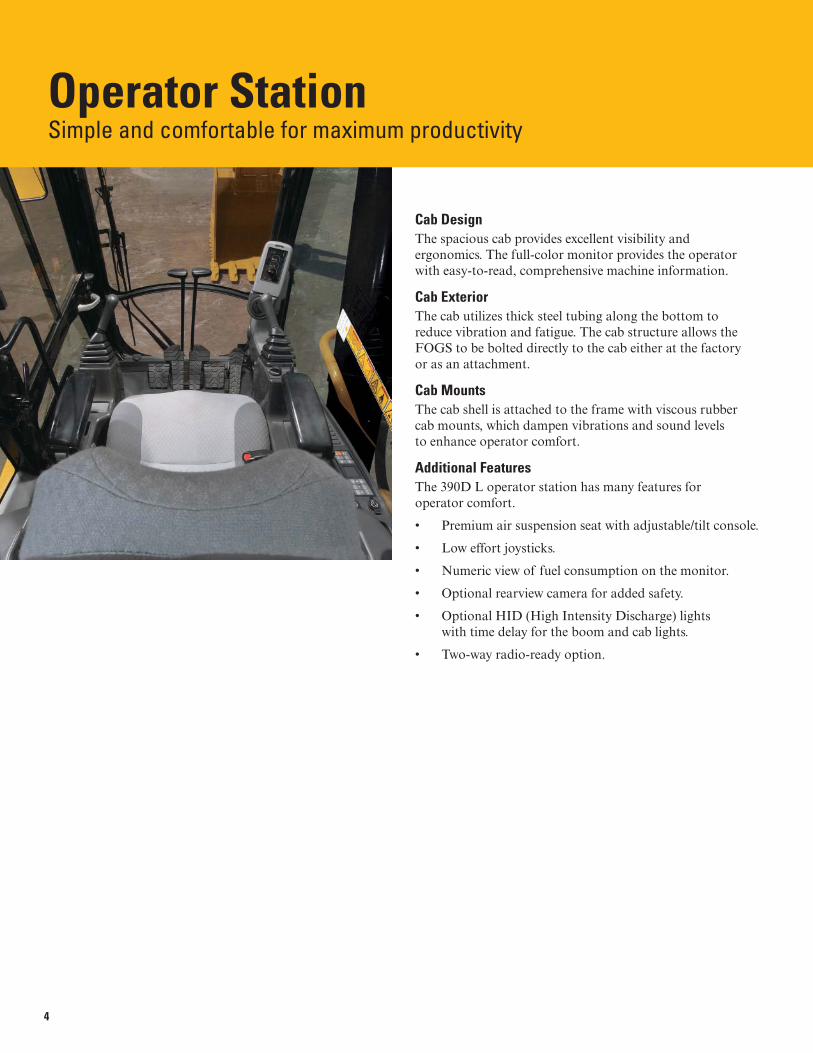
Operator StationSimple and comfortable for maximum productivity
Cab DesignThe spacious cab provides excellent visibility and ergonomics. The full-color monitor provides the operator with easy-to-read, comprehensive machine information.
Cab ExteriorThe cab utilizes thick steel tubing along the bottom to reduce vibration and fatigue. The cab structure allows the FOGS to be bolted directly to the cab either at the factory or as an attachment.
Cab MountsThe cab shell is attached to the frame with viscous rubber cab mounts, which dampen vibrations and sound levels to enhance operator comfort.
Additional FeaturesThe 390D L operator station has many features for operator comfort.
• Premium air suspension seat with adjustable/tilt console.
• Low effort joysticks.
• Numeric view of fuel consumption on the monitor.
• Optional rearview camera for added safety.
• Optional HID (High Intensity Discharge) lights with time delay for the boom and cab lights.
• Two-way radio-ready option.
5
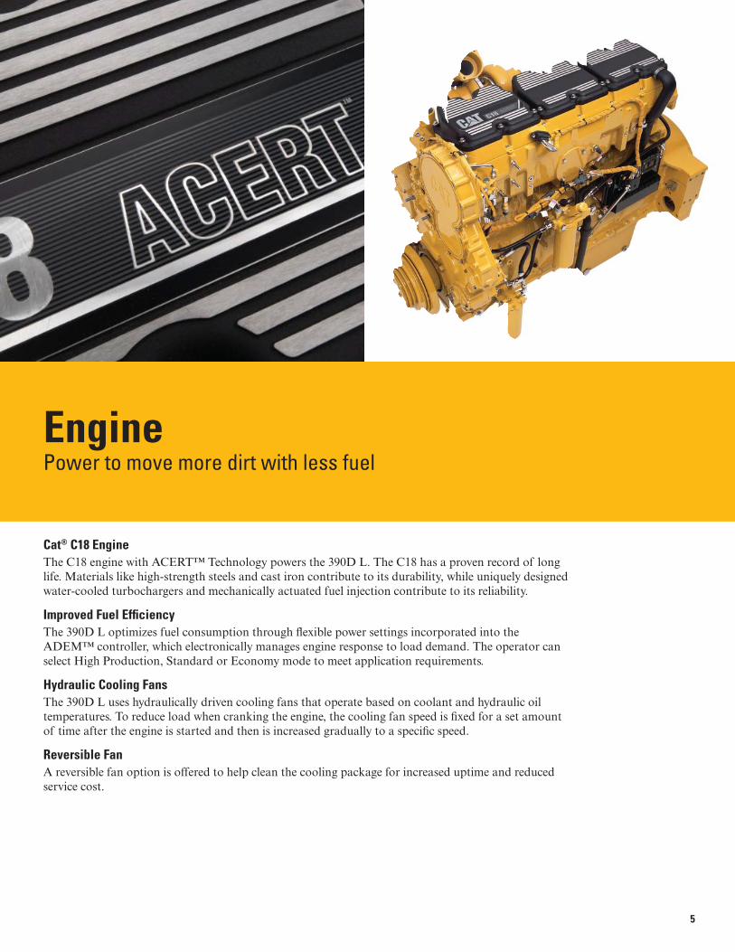
EnginePower to move more dirt with less fuel
Cat® C18 EngineThe C18 engine with ACERT™ Technology powers the 390D L. The C18 has a proven record of long life. Materials like high-strength steels and cast iron contribute to its durability, while uniquely designed water-cooled turbochargers and mechanically actuated fuel injection contribute to its reliability.
Improved Fuel Effi ciencyThe 390D L optimizes fuel consumption through fl exible power settings incorporated into the ADEM™ controller, which electronically manages engine response to load demand. The operator can select High Production, Standard or Economy mode to meet application requirements.
Hydraulic Cooling FansThe 390D L uses hydraulically driven cooling fans that operate based on coolant and hydraulic oil temperatures. To reduce load when cranking the engine, the cooling fan speed is fi xed for a set amount of time after the engine is started and then is increased gradually to a specifi c speed.
Reversible FanA reversible fan option is offered to help clean the cooling package for increased uptime and reduced service cost.

6
Control SystemEasy to view, easy to manage
Monitor DisplayThe monitor is a full-color Liquid Crystal Display (LCD). A master caution lamp blinks ON and OFF when one of the critical conditions below occurs:
• Engine oil pressure low
• Coolant temperature high
• Hydraulic oil temperature high
Under normal conditions or the default condition, the monitor display screen is divided into four areas: clock and throttle dial, gauge, event display and multi-functional display.
Gauge DisplayThree analog gauges – fuel level, hydraulic oil temperature and coolant temperature – are displayed in this area.
Pattern Control ChangerThe standard hand control pattern changer can be accessed through the monitor to utilize either the standard excavator control pattern or backhoe pattern, making it easier for operators to work in the mode they are accustomed.
Electronic JoysticksElectronic joysticks provide features not possible with hydraulic pilot valves:
• Eliminate pilot lines in cab for quieter operation
• Simple pattern change through the monitor
Operator Gain/ResponseThis is used to suit the operator preference or application.
• Faster for quick response
• Slower for more precision
Product LinkProduct Link is a proprietary Caterpillar technology that tracks machine location, product health, hours of use and fuel consumption. This information is transmitted back to customers to help maximize machine productivity.
7
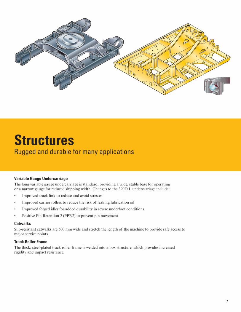
StructuresRugged and durable for many applications
Variable Gauge UndercarriageThe long variable gauge undercarriage is standard, providing a wide, stable base for operating or a narrow gauge for reduced shipping width. Changes to the 390D L undercarriage include:
• Improved track link to reduce and avoid stresses
• Improved carrier rollers to reduce the risk of leaking lubrication oil
• Improved forged idler for added durability in severe underfoot conditions
• Positive Pin Retention 2 (PPR2) to prevent pin movement
CatwalksSlip-resistant catwalks are 500 mm wide and stretch the length of the machine to provide safe access to major service points.
Track Roller FrameThe thick, steel-plated track roller frame is welded into a box structure, which provides increased rigidity and impact resistance.

8
UndercarriageStrong, stable and durable
UndercarriageThe undercarriage supports the swing bearing and upper structure and is the link that transmits the reaction forces from digging to the ground. The strength of the Cat undercarriage plays a major factor in machine stability and durability.
Track Roller FrameThe track roller frame has been improved by installing a longer stroke recoil spring and lowering the front idler. The longer recoil spring improves durability and service life of the undercarriage, and the offset idler increases the stability of the machine while working over the front.
Positive Pin Retention 2 (PPR2)Track links with the PPR2 are provided as standard on the 390D L. The PPR2 is designed to prevent looseness of the track pin in the track link and to reduce stress concentrations. The PPR2 system eliminates pin movement for increased service life.
Carrier RollersThe carrier rollers use a fl oating Duo-Cone seal, which reduces the risk of leaking lubricating oil.
Forged IdlerThe durable forged idler is standard on the 390D L.
9
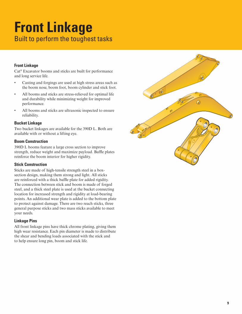
Front LinkageBuilt to perform the toughest tasks
Front LinkageCat® Excavator booms and sticks are built for performance and long service life.
• Casting and forgings are used at high stress areas such as the boom nose, boom foot, boom cylinder and stick foot.
• All booms and sticks are stress-relieved for optimal life and durability while minimizing weight for improved performance.
• All booms and sticks are ultrasonic inspected to ensure reliability.
Bucket LinkageTwo bucket linkages are available for the 390D L. Both are available with or without a lifting eye.
Boom Construction390D L booms feature a large cross section to improve strength, reduce weight and maximize payload. Baffl e plates reinforce the boom interior for higher rigidity.
Stick ConstructionSticks are made of high-tensile strength steel in a box-section design, making them strong and light. All sticks are reinforced with a thick baffl e plate for added rigidity. The connection between stick and boom is made of forged steel, and a thick steel plate is used at the bucket connecting location for increased strength and rigidity at load-bearing points. An additional wear plate is added to the bottom plate to protect against damage. There are two reach sticks, three general purpose sticks and two mass sticks available to meet your needs.
Linkage PinsAll front linkage pins have thick chrome plating, giving them high wear resistance. Each pin diameter is made to distribute the shear and bending loads associated with the stick and to help ensure long pin, boom and stick life.
1
2
3
10
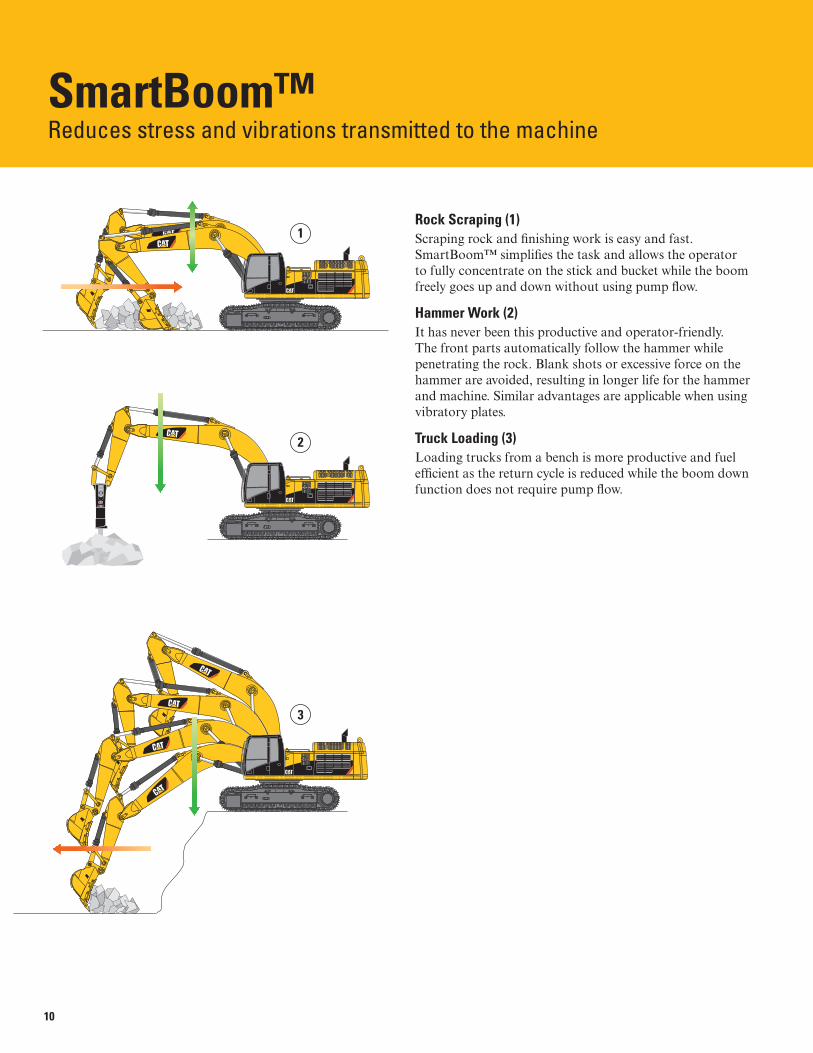
SmartBoom™Reduces stress and vibrations transmitted to the machine
Rock Scraping (1)Scraping rock and fi nishing work is easy and fast. SmartBoom™ simplifi es the task and allows the operator to fully concentrate on the stick and bucket while the boom freely goes up and down without using pump fl ow.
Hammer Work (2)It has never been this productive and operator-friendly. The front parts automatically follow the hammer while penetrating the rock. Blank shots or excessive force on the hammer are avoided, resulting in longer life for the hammer and machine. Similar advantages are applicable when using vibratory plates.
Truck Loading (3)Loading trucks from a bench is more productive and fuel effi cient as the return cycle is reduced while the boom down function does not require pump fl ow.

1 2
3 4
11
Buckets and TeethDesigned and built for rugged work
Optimized PackageCaterpillar offers a wide range of buckets – each designed and fi eld tested to function as an integral part of your excavator. All Cat® Buckets feature K Series™ Ground Engaging Tools (GET). Buckets are available in four levels of durability and are built to take full advantage of the machine’s power.
General Duty (GD)General Duty buckets are designed for use in low impact, low abrasion material such as dirt, loam and mixed compositions of dirt and fi ne gravel.
Heavy Duty (HD)Heavy Duty buckets are the most popular and a good “centerline” choice. This bucket style is a good starting point when application conditions are not known. Heavy Duty buckets are designed for a wide range of impact and abrasion conditions, including mixed dirt, clay and rock.
Severe Duty (SD)Severe Duty buckets are designed for higher abrasion conditions such as shot granite. When compared to the Heavy Duty bucket, wear bars and wear plates are substantially thicker and larger for added protection.
Extreme Duty (XD)Extreme Duty buckets are designed for very high abrasion conditions such as granite quarries. Corner shrouds have been added, and side wear plates are larger for added protection.
1) Severe Duty 2) Heavy Duty 3) General Duty 4) Extreme Duty
12
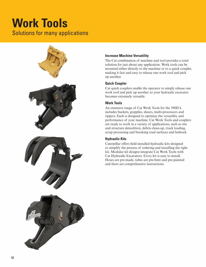
Work ToolsSolutions for many applications
Increase Machine VersatilityThe Cat combination of machine and tool provides a total solution for just about any application. Work tools can be mounted either directly to the machine or to a quick coupler, making it fast and easy to release one work tool and pick up another.
Quick CouplerCat quick couplers enable the operator to simply release one work tool and pick up another so your hydraulic excavator becomes extremely versatile.
Work ToolsAn extensive range of Cat Work Tools for the 390D L includes buckets, grapples, shears, multi-processors and rippers. Each is designed to optimize the versatility and performance of your machine. Cat Work Tools and couplers are ready to work in a variety of applications, such as site and structure demolition, debris clean-up, truck loading, scrap processing and breaking road surfaces and bedrock.
Hydraulic KitsCaterpillar offers fi eld-installed hydraulic kits designed to simplify the process of ordering and installing the right kit. Modular kit designs integrate Cat Work Tools with Cat Hydraulic Excavators. Every kit is easy to install. Hoses are pre-made, tubes are pre-bent and pre-painted and there are comprehensive instructions.

13
EnvironmentBuilt to meet a range of requirements
EmissionsACERT™ Technology is a differentiated technology that reduces emissions at the point of combustion. It capitalizes on proven Caterpillar leadership in three core engine systems: fuel, air and electronics.
Electro Magnetic ComplianceThe 390D L meets the following EMC (Electro Magnetic Compliance) requirements:
• ISO 13766 Earth Moving Machinery – Electromagnetic compliance
• EU Directive 89/336/EEC
• Aus EMC Framework
Fluid ManagementMany serviceability elements are designed into the 390D L to limit fl uid spillage while performing routing maintenance.
FiltersHydraulic return fi lters are vertically mounted, capsule-type with shutoffs in the inlet and outlet ports.
Ecology DrainsEcology drains for the fuel and hydraulic tanks allow fl uids to be captured in a container when draining the tanks.
Certifi ed RebuildWhen most other manufacturers’ models require replacement, Cat equipment can be rebuilt using many remanufactured parts. This means less materials going to landfi lls.
14
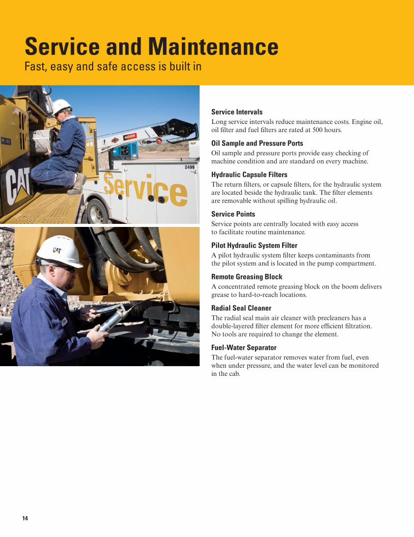
Service and MaintenanceFast, easy and safe access is built in
Service IntervalsLong service intervals reduce maintenance costs. Engine oil, oil fi lter and fuel fi lters are rated at 500 hours.
Oil Sample and Pressure PortsOil sample and pressure ports provide easy checking of machine condition and are standard on every machine.
Hydraulic Capsule FiltersThe return fi lters, or capsule fi lters, for the hydraulic system are located beside the hydraulic tank. The fi lter elements are removable without spilling hydraulic oil.
Service PointsService points are centrally located with easy access to facilitate routine maintenance.
Pilot Hydraulic System FilterA pilot hydraulic system fi lter keeps contaminants from the pilot system and is located in the pump compartment.
Remote Greasing BlockA concentrated remote greasing block on the boom delivers grease to hard-to-reach locations.
Radial Seal CleanerThe radial seal main air cleaner with precleaners has a double-layered fi lter element for more effi cient fi ltration. No tools are required to change the element.
Fuel-Water SeparatorThe fuel-water separator removes water from fuel, even when under pressure, and the water level can be monitored in the cab.

15
Complete Customer SupportCat® dealer services to help you operate longer with lower costs
Product SupportCat dealers utilize a worldwide parts network to minimize machine downtime. Plus you can save money with Cat remanufactured components.
Machine SelectionMake detailed comparisons of machines you are considering. What are the job requirements and machine attachments? What production is needed? Your Cat dealer can provide recommendations.
PurchaseConsider fi nancing options and day-to-day operating costs. Look at dealer services that can be included in the machine’s cost to yield lower owning and operating costs over time.
Customer Support AgreementsCat dealers offer a variety of customer support agreements and work with you to develop a plan to meet specifi c needs. These plans can cover the entire machine, including attachments, to help protect your investment.
OperationImproving operating techniques can boost your profi ts. Your Cat dealer has videos, literature and other ideas to help you increase productivity. Caterpillar also offers simulators and certifi ed operator training to help maximize the return on your investment.
ReplacementRepair, rebuild or replace? Your Cat dealer can help you evaluate the cost involved so you can make the right choice.
16
390D L Hydraulic Excavator Specifi cations
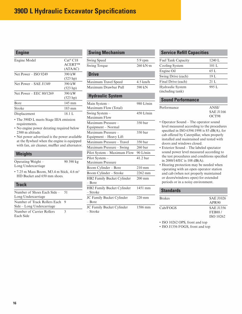
Engine
Engine Model Cat® C18 ACERT™ (ATAAC)
Net Power – ISO 9249 390 kW (523 hp)
Net Power – SAE J1349 390 kW (523 hp)
Net Power – EEC 80/1269 390 kW (523 hp)
Bore 145 mm
Stroke 183 mm
Displacement 18.1 L
• The 390D L meets Stage IIIA emission requirements.
• No engine power derating required below 2300 m altitude.
• Net power advertised is the power available at the fl ywheel when the engine is equipped with fan, air cleaner, muffl er and alternator.
Weights
Operating Weight – Long Undercarriage
90 390 kg
• 7.25 m Mass Boom, M3.4 m Stick, 4.6 m³ HD Bucket and 650 mm shoes.
Track
Number of Shoes Each Side – Long Undercarriage
51
Number of Track Rollers Each Side – Long Undercarriage
9
Number of Carrier Rollers Each Side
3
Swing Mechanism
Swing Speed 5.9 rpm
Swing Torque 260 kN·m
Drive
Maximum Travel Speed 4.5 km/h
Maximum Drawbar Pull 590 kN
Hydraulic System
Main System – Maximum Flow (Total)
980 L/min
Swing System – Maximum Flow
450 L/min
Maximum Pressure – Equipment – Normal
350 bar
Maximum Pressure – Equipment – Heavy Lift
350 bar
Maximum Pressure – Travel 350 bar
Maximum Pressure – Swing 260 bar
Pilot System – Maximum Flow 90 L/min
Pilot System – Maximum Pressure
41.2 bar
Boom Cylinder – Bore 210 mm
Boom Cylinder – Stroke 2262 mm
HB2 Family Bucket Cylinder – Bore
200 mm
HB2 Family Bucket Cylinder – Stroke
1451 mm
JC Family Bucket Cylinder – Bore
220 mm
JC Family Bucket Cylinder – Stroke
1586 mm
Service Refi ll Capacities
Fuel Tank Capacity 1240 L
Cooling System 101 L
Engine Oil 65 L
Swing Drive (each) 19 L
Final Drive (each) 21 L
Hydraulic System (including tank)
995 L
Sound Performance
Performance ANSI/SAE J1166 OCT98
• Operator Sound – The operator sound level measured according to the procedures specifi ed in ISO 6394:1998 is 85 dB(A), for cab offered by Caterpillar, when properly installed and maintained and tested with doors and windows closed.
• Exterior Sound – The labeled spectator sound power level measured according to the test procedures and conditions specifi ed in 2000/14/EC is 108 dB(A).
• Hearing protection may be needed when operating with an open operator station and cab (when not properly maintained or doors/windows open) for extended periods or in a noisy environment.
Standards
Brakes SAE J1026 APR90
Cab/FOGS SAE J1356 FEB88 / ISO 10262
• ISO 10262 OPS, front and top• ISO J1356 FOGS, front and top
17
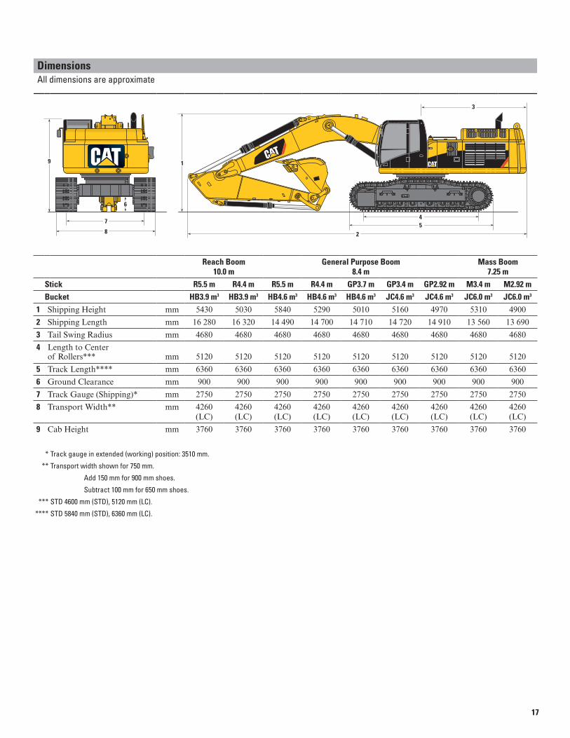
Dimensions All dimensions are approximate
Reach Boom General Purpose Boom Mass Boom 10.0 m 8.4 m 7.25 m
Stick R5.5 m R4.4 m R5.5 m R4.4 m GP3.7 m GP3.4 m GP2.92 m M3.4 m M2.92 m
Bucket HB3.9 m3 HB3.9 m3 HB4.6 m3 HB4.6 m3 HB4.6 m3 JC4.6 m3 JC4.6 m3 JC6.0 m3 JC6.0 m3
1 Shipping Height mm 5430 5030 5840 5290 5010 5160 4970 5310 4900
2 Shipping Length mm 16 280 16 320 14 490 14 700 14 710 14 720 14 910 13 560 13 690
3 Tail Swing Radius mm 4680 4680 4680 4680 4680 4680 4680 4680 4680
4 Length to Center of Rollers*** mm 5120 5120 5120 5120 5120 5120 5120 5120 5120
5 Track Length**** mm 6360 6360 6360 6360 6360 6360 6360 6360 6360
6 Ground Clearance mm 900 900 900 900 900 900 900 900 900
7 Track Gauge (Shipping)* mm 2750 2750 2750 2750 2750 2750 2750 2750 2750
8 Transport Width** mm 4260 4260 4260 4260 4260 4260 4260 4260 4260 (LC) (LC) (LC) (LC) (LC) (LC) (LC) (LC) (LC)
9 Cab Height mm 3760 3760 3760 3760 3760 3760 3760 3760 3760
* Track gauge in extended (working) position: 3510 mm.
** Transport width shown for 750 mm.
Add 150 mm for 900 mm shoes.
Subtract 100 mm for 650 mm shoes.
*** STD 4600 mm (STD), 5120 mm (LC).
**** STD 5840 mm (STD), 6360 mm (LC).
3
1
45
8
7
9
6
2

18
390D L Hydraulic Excavator Specifi cations
Working Ranges
Reach Boom General Purpose Boom Mass Boom 10.0 m 8.4 m 7.25 m
Stick R5.5 m R4.4 m R5.5 m R4.4 m GP3.7 m GP3.4 m GP2.92 m M3.4 m M2.92 m
Bucket HB3.9 m3 HB3.9 m3 HB4.6 m3 HB4.6 m3 HB4.6 m3 JC4.6 m3 JC4.6 m3 JC6.0 m3 JC6.0 m3
1 Maximum Digging Depth mm 11 810 10 710 10 760 9660 8960 8690 8220 7650 7170
2 Maximum Reach at Ground Line mm 17 250 16 230 15 730 14 690 14 040 13 910 13 480 12 690 12 240
3 Maximum Loading Height mm 10 950 10 520 9720 9270 8980 9090 8910 8200 7980
4 Minimum Loading Height mm 3310 4410 1940 3040 3740 4020 4480 3200 3670
5 Maximum Depth Cut for 2240 mm Level Bottom mm 11 710 10 600 10 660 9550 8840 8560 8080 7520 7030
6 Maximum Vertical Wall Digging Depth mm 8390 7380 7860 6850 5940 6190 5950 5100 4700
Bucket Digging Force
(SAE) kN 322 321 322 321 321 412 411 404 404
(ISO) kN 365 363 365 363 363 471 470 471 470
Stick Digging Force
(SAE) kN 230 268 230 268 300 315 337 314 342
(ISO) kN 236 276 236 276 310 325 350 325 356
1
65
3
4
2
1
1
6
5
3
4
2
2
1
6
5
3
4
2
3
1 2 3

19
Operating Weight* and Ground Pressure
Track
900 mm Shoes 750 mm Shoes 650 mm Shoes
kg bar kg bar kg bar
Reach Boom – 10.0 m
Bucket – 3.9 m3
R5.5 m 90 070 0.88 88 950 1.0 88 080 1.2
R4.4 m 89 570 0.88 88 450 1.0 87 580 1.1
General Purpose Boom – 8.4 m
Bucket – 4.6 m3
R5.5 m 88 690 0.87 87 570 1.0 86 690 1.2
R4.4 m 88 180 0.86 87 070 1.0 86 190 1.2
GP3.4 m 91 050 0.89 89 930 1.0 89 060 1.2
GP2.92 m 90 680 0.89 89 570 1.0 88 690 1.2
Mass Boom – 7.25 m
Bucket – 6.0 m3
M3.4 m 92 380 0.90 91 260 1.0 90 390 1.2
M2.92 m 92 130 0.90 91 010 1.0 90 140 1.2
* Operating weight includes full fuel tank and 75 kg operator.
Major Component Weights
kg
Base machine with counterweight and 750 mm shoes (without front linkage) 67 950
Two boom cylinders 1720
Boom (includes lines, pins, stick cylinder)
Reach Boom – 10.0 m 9750
General Purpose Boom – 8.4 m 8310
Mass Boom – 7.25 m 8480
Stick (includes lines, pins, bucket cylinder and linkage)
R5.5 m 5430
R4.4 m 4930
GP3.4 m 5270
GP2.92 m 4910
M3.4 m 5420
M2.92 m 5170

20
390D L Hydraulic Excavator Specifi cations
390D L Bucket Specifications and Compatibility – EAME
Linkage
Width Capacity Weight Fill Reach Boom General Purpose Boom ME Boom
mm m3 kg % R4.4HB2 R5.5HB2 R4.4HB2 R5.5HB2 G3.7HB2 G2.9JC G3.4JC M2.9JC M3.4JC
Without Quick Coupler
General Duty (GD) HB2 1350 3.0 3406 100% – – – –
HB2 1650 3.9 3794 100% – – – –
HB2 1900 4.6 4155 100% – – – –
HB2 1100 2.2 2856 100% – – – –
HB2 1350 2.9 3187 100% – – – –
HB2 1650 3.7 3650 100% – – – –
HB2 1900 4.3 3923 100% – – – –
HB2 2000 4.6 4032 100% – – – –
JC 2300 5.7 5822 100% – – – – –
JC 2420 6.0 6004 100% – – – – –
JC 2575 6.5 6238 100% – – – – –
General Duty XL (GDXL) HB2 2000 5.3 4400 100% – – – –
HB2 2250 6.0 4796 100% – – – –
Heavy Duty (HD) JC 1750 4.1 4799 100% – – – – –
JC 2090 5.1 5441 100% – – – – –
JC 2300 5.7 5892 100% – – – – –
Severe Duty (SD) HB2 1100 2.3 3282 90% – – – –
HB2 1350 3.0 3736 90% – – – –
HB2 1650 3.9 4163 90% – – – –
HB2 1900 4.6 4553 90% – – – –
JC 1960 4.6 6229 90% – – – – –
JC 2240 5.4 6809 90% – – – – –
JC 2350 5.7 7015 90% – – – – –
JC 2440 6.0 7342 90% – – – – –
Extreme Duty (XD) JC 2090 5.0 6557 90% – – – – –
JC 2240 5.4 7733 90% – – – – –
JC 2350 5.7 7968 90% – – – – –
Maximum dynamic load pin-on (payload + bucket) kg 7535 6350 10 420 8850 12 530 12 420 11 430 15 850 14 600
With Quick Coupler (CW-70)
Severe Duty (SD) JC 2240 5.4 6559 90% – – – – –
JC 2350 5.7 6765 90% – – – – –
Maximum dynamic load with CW coupler (payload + bucket) kg 6115 4930 9000 7430 11 110 11 000 10 010 14 430 13 180
The above figures are based on maximum recommended dynamic working weights with front linkage fully extended at ground line with bucket curled. They do not exceed a stability ratio of 1.25.
1800 kg/m3 or greater
1500 kg/m3 or less
1200 kg/m3 or less
Capacity based on ISO 7451. Not Recommended
Bucket weights include HD Long tips.

21
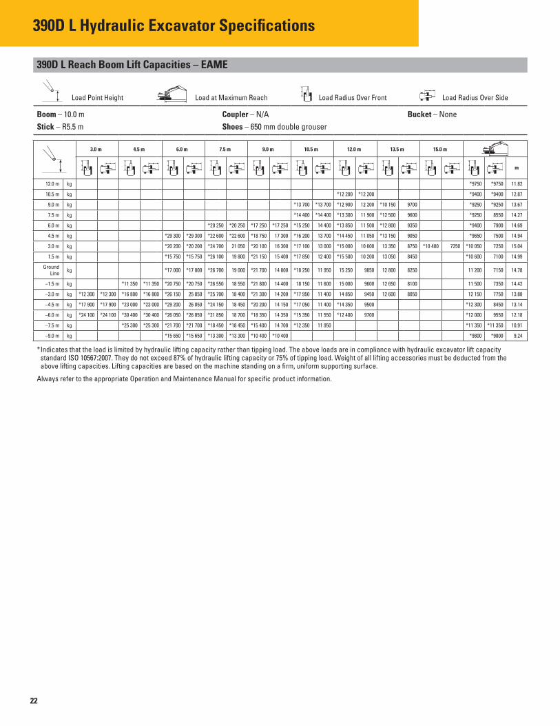
390D L Reach Boom Lift Capacities – EAME
Load Point Height Load at Maximum Reach Load Radius Over Front Load Radius Over Side
Boom – 10.0 m Coupler – N/A Bucket – None
Stick – R5.5 m Shoes – 750 mm double grouser
3.0 m 4.5 m 6.0 m 7.5 m 9.0 m 10.5 m 12.0 m 13.5 m 15.0 m
m
12.0 m kg *9750 *9750 11.82
10.5 m kg *12 200 *12 200 *9400 *9400 12.87
9.0 m kg *13 700 *13 700 *12 900 12 350 *10 150 9800 *9250 *9250 13.67
7.5 m kg *14 400 *14 400 *13 300 12 050 *12 500 9700 *9250 8650 14.27
6.0 m kg *20 250 *20 250 *17 250 *17 250 *15 250 14 500 *13 850 11 650 *12 800 9450 *9400 8000 14.69
4.5 m kg *29 300 *29 300 *22 600 *22 600 *18 750 17 500 *16 200 13 850 *14 450 11 200 *13 150 9150 *9650 7600 14.94
3.0 m kg *20 200 *20 200 *24 700 21 250 *20 100 16 450 *17 100 13 150 *15 000 10 700 *13 450 8850 *10 400 7350 *10 050 7300 15.04
1.5 m kg *15 750 *15 750 *26 100 20 000 *21 150 15 600 *17 850 12 550 *15 500 10 300 13 200 8600 *10 600 7200 14.99
Ground Line
kg *17 000 *17 000 *26 700 19 200 *21 700 14 950 *18 250 12 050 15 400 9950 12 950 8350 11 300 7250 14.78
–1.5 m kg *11 350 *11 350 *20 750 *20 750 *26 550 18 800 *21 800 14 550 *18 350 11 750 15 150 9700 12 800 8200 11 650 7450 14.42
–3.0 m kg *12 300 *12 300 *16 800 *16 800 *26 150 26 150 *25 700 18 650 *21 300 14 350 *17 950 11 550 15 000 9600 12 750 8150 12 300 7850 13.88
–4.5 m kg *17 900 *17 900 *23 000 *23 000 *29 200 26 350 *24 150 18 700 *20 200 14 350 *17 050 11 550 *14 350 9600 *12 300 8550 13.14
–6.0 m kg *24 100 *24 100 *30 400 *30 400 *26 050 *26 050 *21 850 18 950 *18 350 14 500 *15 350 11 700 *12 400 9800 *12 000 9650 12.18
–7.5 m kg *25 300 *25 300 *21 700 *21 700 *18 450 *18 450 *15 400 14 900 *12 350 12 100 *11 350 *11 350 10.91
–9.0 m kg *15 650 *15 650 *13 300 *13 300 *10 400 *10 400 *9800 *9800 9.24
Indicates that the load is limited by hydraulic lifting capacity rather than tipping load. The above loads are in compliance with hydraulic excavator lift capacity * standard ISO 10567:2007. They do not exceed 87% of hydraulic lifting capacity or 75% of tipping load. Weight of all lifting accessories must be deducted from the above lifting capacities. Lifting capacities are based on the machine standing on a firm, uniform supporting surface.
Always refer to the appropriate Operation and Maintenance Manual for specific product information.
22
390D L Hydraulic Excavator Specifi cations
390D L Reach Boom Lift Capacities – EAME
Load Point Height Load at Maximum Reach Load Radius Over Front Load Radius Over Side
Boom – 10.0 m Coupler – N/A Bucket – None
Stick – R5.5 m Shoes – 650 mm double grouser
3.0 m 4.5 m 6.0 m 7.5 m 9.0 m 10.5 m 12.0 m 13.5 m 15.0 m
m
12.0 m kg *9750 *9750 11.82
10.5 m kg *12 200 *12 200 *9400 *9400 12.87
9.0 m kg *13 700 *13 700 *12 900 12 200 *10 150 9700 *9250 *9250 13.67
7.5 m kg *14 400 *14 400 *13 300 11 900 *12 500 9600 *9250 8550 14.27
6.0 m kg *20 250 *20 250 *17 250 *17 250 *15 250 14 400 *13 850 11 500 *12 800 9350 *9400 7900 14.69
4.5 m kg *29 300 *29 300 *22 600 *22 600 *18 750 17 300 *16 200 13 700 *14 450 11 050 *13 150 9050 *9650 7500 14.94
3.0 m kg *20 200 *20 200 *24 700 21 050 *20 100 16 300 *17 100 13 000 *15 000 10 600 13 350 8750 *10 400 7250 *10 050 7250 15.04
1.5 m kg *15 750 *15 750 *26 100 19 800 *21 150 15 400 *17 850 12 400 *15 500 10 200 13 050 8450 *10 600 7100 14.99
Ground Line
kg *17 000 *17 000 *26 700 19 000 *21 700 14 800 *18 250 11 950 15 250 9850 12 800 8250 11 200 7150 14.78
–1.5 m kg *11 350 *11 350 *20 750 *20 750 *26 550 18 550 *21 800 14 400 18 150 11 600 15 000 9600 12 650 8100 11 500 7350 14.42
–3.0 m kg *12 300 *12 300 *16 800 *16 800 *26 150 25 850 *25 700 18 400 *21 300 14 200 *17 950 11 400 14 850 9450 12 600 8050 12 150 7750 13.88
–4.5 m kg *17 900 *17 900 *23 000 *23 000 *29 200 26 050 *24 150 18 450 *20 200 14 150 *17 050 11 400 *14 350 9500 *12 300 8450 13.14
–6.0 m kg *24 100 *24 100 *30 400 *30 400 *26 050 *26 050 *21 850 18 700 *18 350 14 350 *15 350 11 550 *12 400 9700 *12 000 9550 12.18
–7.5 m kg *25 300 *25 300 *21 700 *21 700 *18 450 *18 450 *15 400 14 700 *12 350 11 950 *11 350 *11 350 10.91
–9.0 m kg *15 650 *15 650 *13 300 *13 300 *10 400 *10 400 *9800 *9800 9.24
Indicates that the load is limited by hydraulic lifting capacity rather than tipping load. The above loads are in compliance with hydraulic excavator lift capacity * standard ISO 10567:2007. They do not exceed 87% of hydraulic lifting capacity or 75% of tipping load. Weight of all lifting accessories must be deducted from the above lifting capacities. Lifting capacities are based on the machine standing on a firm, uniform supporting surface.
Always refer to the appropriate Operation and Maintenance Manual for specific product information.
23
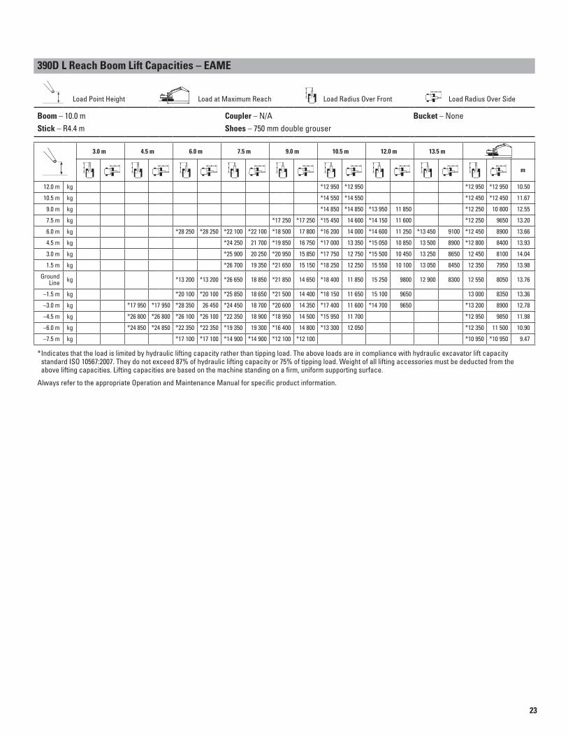
390D L Reach Boom Lift Capacities – EAME
Load Point Height Load at Maximum Reach Load Radius Over Front Load Radius Over Side
Boom – 10.0 m Coupler – N/A Bucket – None
Stick – R4.4 m Shoes – 750 mm double grouser
3.0 m 4.5 m 6.0 m 7.5 m 9.0 m 10.5 m 12.0 m 13.5 m
m
12.0 m kg *12 950 *12 950 *12 950 *12 950 10.50
10.5 m kg *14 550 *14 550 *12 450 *12 450 11.67
9.0 m kg *14 850 *14 850 *13 950 11 850 *12 250 10 800 12.55
7.5 m kg *17 250 *17 250 *15 450 14 600 *14 150 11 600 *12 250 9650 13.20
6.0 m kg *28 250 *28 250 *22 100 *22 100 *18 500 17 800 *16 200 14 000 *14 600 11 250 *13 450 9100 *12 450 8900 13.66
4.5 m kg *24 250 21 700 *19 850 16 750 *17 000 13 350 *15 050 10 850 13 500 8900 *12 800 8400 13.93
3.0 m kg *25 900 20 250 *20 950 15 850 *17 750 12 750 *15 500 10 450 13 250 8650 12 450 8100 14.04
1.5 m kg *26 700 19 350 *21 650 15 150 *18 250 12 250 15 550 10 100 13 050 8450 12 350 7950 13.98
Ground Line kg *13 200 *13 200 *26 650 18 850 *21 850 14 650 *18 400 11 850 15 250 9800 12 900 8300 12 550 8050 13.76
–1.5 m kg *20 100 *20 100 *25 850 18 650 *21 500 14 400 *18 150 11 650 15 100 9650 13 000 8350 13.36
–3.0 m kg *17 950 *17 950 *28 350 26 450 *24 450 18 700 *20 600 14 350 *17 400 11 600 *14 700 9650 *13 200 8900 12.78
–4.5 m kg *26 800 *26 800 *26 100 *26 100 *22 350 18 900 *18 950 14 500 *15 950 11 700 *12 950 9850 11.98
–6.0 m kg *24 850 *24 850 *22 350 *22 350 *19 350 19 300 *16 400 14 800 *13 300 12 050 *12 350 11 500 10.90
–7.5 m kg *17 100 *17 100 *14 900 *14 900 *12 100 *12 100 *10 950 *10 950 9.47
Indicates that the load is limited by hydraulic lifting capacity rather than tipping load. The above loads are in compliance with hydraulic excavator lift capacity * standard ISO 10567:2007. They do not exceed 87% of hydraulic lifting capacity or 75% of tipping load. Weight of all lifting accessories must be deducted from the above lifting capacities. Lifting capacities are based on the machine standing on a firm, uniform supporting surface.
Always refer to the appropriate Operation and Maintenance Manual for specific product information.
24
390D L Hydraulic Excavator Specifi cations
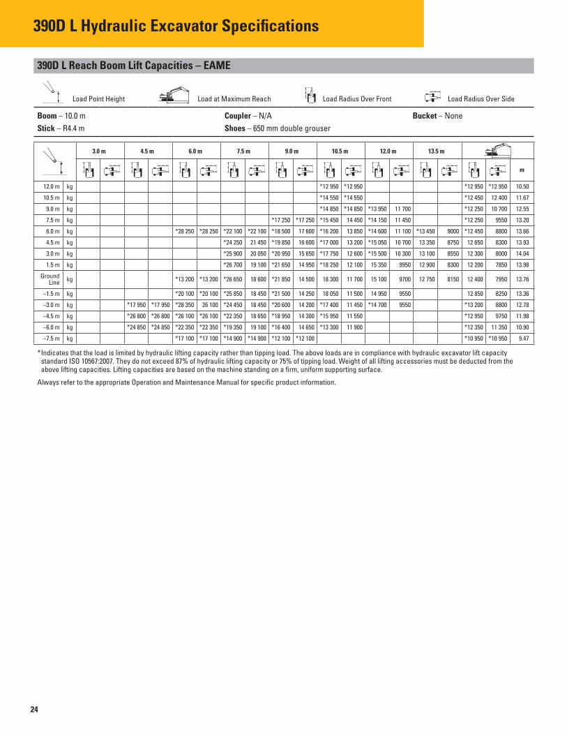
390D L Reach Boom Lift Capacities – EAME
Load Point Height Load at Maximum Reach Load Radius Over Front Load Radius Over Side
Boom – 10.0 m Coupler – N/A Bucket – None
Stick – R4.4 m Shoes – 650 mm double grouser
3.0 m 4.5 m 6.0 m 7.5 m 9.0 m 10.5 m 12.0 m 13.5 m
m
12.0 m kg *12 950 *12 950 *12 950 *12 950 10.50
10.5 m kg *14 550 *14 550 *12 450 12 400 11.67
9.0 m kg *14 850 *14 850 *13 950 11 700 *12 250 10 700 12.55
7.5 m kg *17 250 *17 250 *15 450 14 450 *14 150 11 450 *12 250 9550 13.20
6.0 m kg *28 250 *28 250 *22 100 *22 100 *18 500 17 600 *16 200 13 850 *14 600 11 100 *13 450 9000 *12 450 8800 13.66
4.5 m kg *24 250 21 450 *19 850 16 600 *17 000 13 200 *15 050 10 700 13 350 8750 12 650 8300 13.93
3.0 m kg *25 900 20 050 *20 950 15 650 *17 750 12 600 *15 500 10 300 13 100 8550 12 300 8000 14.04
1.5 m kg *26 700 19 100 *21 650 14 950 *18 250 12 100 15 350 9950 12 900 8300 12 200 7850 13.98
Ground Line kg *13 200 *13 200 *26 650 18 600 *21 850 14 500 18 300 11 700 15 100 9700 12 750 8150 12 400 7950 13.76
–1.5 m kg *20 100 *20 100 *25 850 18 450 *21 500 14 250 18 050 11 500 14 950 9550 12 850 8250 13.36
–3.0 m kg *17 950 *17 950 *28 350 26 100 *24 450 18 450 *20 600 14 200 *17 400 11 450 *14 700 9550 *13 200 8800 12.78
–4.5 m kg *26 800 *26 800 *26 100 *26 100 *22 350 18 650 *18 950 14 300 *15 950 11 550 *12 950 9750 11.98
–6.0 m kg *24 850 *24 850 *22 350 *22 350 *19 350 19 100 *16 400 14 650 *13 300 11 900 *12 350 11 350 10.90
–7.5 m kg *17 100 *17 100 *14 900 *14 900 *12 100 *12 100 *10 950 *10 950 9.47
Indicates that the load is limited by hydraulic lifting capacity rather than tipping load. The above loads are in compliance with hydraulic excavator lift capacity * standard ISO 10567:2007. They do not exceed 87% of hydraulic lifting capacity or 75% of tipping load. Weight of all lifting accessories must be deducted from the above lifting capacities. Lifting capacities are based on the machine standing on a firm, uniform supporting surface.
Always refer to the appropriate Operation and Maintenance Manual for specific product information.

25
390D L General Boom Lift Capacities – EAME
Load Point Height Load at Maximum Reach Load Radius Over Front Load Radius Over Side
Boom – 8.4 m Coupler – N/A Bucket – None
Stick – R5.5 m Shoes – 750 mm double grouser
3.0 m 4.5 m 6.0 m 7.5 m 9.0 m 10.5 m 12.0 m 13.5 m
m
12.0 m kg *9050 *9050 9.83
10.5 m kg *10 950 *10 950 *8500 *8500 11.07
9.0 m kg *13 000 *13 000 *8200 *8200 12.00
7.5 m kg *14 450 *14 450 *11 500 *11 500 *8050 *8050 12.68
6.0 m kg *17 550 *17 550 *16 200 15 250 *13 500 12 200 *8100 *8100 13.15
4.5 m kg *27 100 *27 100 *22 200 *22 200 *19 200 18 800 *17 150 14 750 *15 400 11 900 *8250 *8250 13.43
3.0 m kg *31 500 *31 500 *24 800 23 600 *20 800 18 000 *18 200 14 250 *16 300 11 550 *9000 *9000 *8600 *8600 13.54
1.5 m kg *34 800 30 950 *26 950 22 400 *22 200 17 200 *19 050 13 750 16 700 11 200 *9050 *9050 13.48
Ground Line kg *19 000 *19 000 *36 450 29 700 *28 300 21 500 *23 150 16 600 *19 650 13 300 16 400 10 950 *9750 9450 13.25
–1.5 m kg *14 250 *14 250 *23 200 *23 200 *36 600 29 050 *28 750 20 950 *23 500 16 200 19 700 13 000 16 250 10 800 *10 700 9800 12.84
–3.0 m kg *20 200 *20 200 *29 400 *29 400 *35 350 28 800 *28 150 20 650 *23 050 15 950 *19 250 12 900 *15 550 10 750 *12 200 10 500 12.23
–4.5 m kg *27 050 *27 050 *37 750 *37 750 *32 850 28 900 *26 400 20 650 *21 650 15 950 *17 700 12 900 *14 500 11 650 11.39
–6.0 m kg *35 550 *35 550 *35 950 *35 950 *28 700 *28 700 *23 250 20 900 *18 750 16 200 *14 900 13 650 10.26
–7.5 m kg *27 300 *27 300 *22 250 *22 250 *17 700 *17 700 *13 650 *13 650 8.71
Indicates that the load is limited by hydraulic lifting capacity rather than tipping load. The above loads are in compliance with hydraulic excavator lift capacity * standard ISO 10567:2007. They do not exceed 87% of hydraulic lifting capacity or 75% of tipping load. Weight of all lifting accessories must be deducted from the above lifting capacities. Lifting capacities are based on the machine standing on a firm, uniform supporting surface.
Always refer to the appropriate Operation and Maintenance Manual for specific product information.

26
390D L Hydraulic Excavator Specifi cations
390D L General Boom Lift Capacities – EAME
Load Point Height Load at Maximum Reach Load Radius Over Front Load Radius Over Side
Boom – 8.4 m Coupler – N/A Bucket – None
Stick – R5.5 m Shoes – 650 mm double grouser
3.0 m 4.5 m 6.0 m 7.5 m 9.0 m 10.5 m 12.0 m 13.5 m
m
12.0 m kg *9050 *9050 9.83
10.5 m kg *10 950 *10 950 *8500 *8500 11.07
9.0 m kg *13 000 *13 000 *8200 *8200 12.00
7.5 m kg *14 450 *14 450 *11 500 *11 500 *8050 *8050 12.68
6.0 m kg *17 550 *17 550 *16 200 15 150 *13 500 12 050 *8100 *8100 13.15
4.5 m kg *27 100 *27 100 *22 200 *22 200 *19 200 18 650 *17 150 14 650 *15 400 11 750 *8250 *8250 13.43
3.0 m kg *31 500 *31 500 *24 800 23 350 *20 800 17 800 *18 200 14 100 *16 300 11 400 *9000 *9000 *8600 *8600 13.54
1.5 m kg *34 800 30 650 *26 950 22 150 *22 200 17 050 *19 050 13 600 16 500 11 100 *9050 *9050 13.48
Ground Line kg *19 000 *19 000 *36 450 29 400 *28 300 21 300 *23 150 16 450 *19 650 13 150 16 250 10 850 *9750 9350 13.25
–1.5 m kg *14 250 *14 250 *23 200 *23 200 *36 600 28 750 *28 750 20 700 *23 500 16 000 19 500 12 900 16 050 10 650 *10 700 9700 12.84
–3.0 m kg *20 200 *20 200 *29 400 *29 400 *35 350 28 500 *28 150 20 450 *23 050 15 800 *19 250 12 750 *15 550 10 600 *12 200 10 350 12.23
–4.5 m kg *27 050 *27 050 *37 750 *37 750 *32 850 28 600 *26 400 20 450 *21 650 15 750 *17 700 12 750 *14 500 11 500 11.39
–6.0 m kg *35 550 *35 550 *35 950 *35 950 *28 700 *28 700 *23 250 20 700 *18 750 16 000 *14 900 13 500 10.26
–7.5 m kg *27 300 *27 300 *22 250 *22 250 *17 700 *17 700 *13 650 *13 650 8.71
Indicates that the load is limited by hydraulic lifting capacity rather than tipping load. The above loads are in compliance with hydraulic excavator lift capacity * standard ISO 10567:2007. They do not exceed 87% of hydraulic lifting capacity or 75% of tipping load. Weight of all lifting accessories must be deducted from the above lifting capacities. Lifting capacities are based on the machine standing on a firm, uniform supporting surface.
Always refer to the appropriate Operation and Maintenance Manual for specific product information.

27
390D L General Boom Lift Capacities – EAME
Load Point Height Load at Maximum Reach Load Radius Over Front Load Radius Over Side
Boom – 8.4 m Coupler – N/A Bucket – None
Stick – R4.4 m Shoes – 750 mm double grouser
3.0 m 4.5 m 6.0 m 7.5 m 9.0 m 10.5 m 12.0 m
m
10.5 m kg *15 350 *15 350 *11 350 *11 350 9.79
9.0 m kg *17 350 *17 350 *13 350 *13 350 *10 900 *10 900 10.82
7.5 m kg *18 050 *18 050 *16 900 15 150 *10 700 *10 700 11.57
6.0 m kg *21 900 *21 900 *19 250 18 950 *17 500 14 800 *11 750 *11 750 *10 750 *10 750 12.09
4.5 m kg *30 450 *30 450 *24 300 23 950 *20 650 18 200 *18 250 14 350 *15 150 11 550 *11 050 10 900 12.40
3.0 m kg *34 200 31 400 *26 500 22 750 *22 000 17 450 *19 050 13 900 16 750 11 300 *11 500 10 550 12.52
1.5 m kg *36 300 29 900 *28 100 21 750 *23 050 16 800 *19 650 13 450 16 500 11 050 *12 200 10 450 12.46
Ground Line kg *36 650 29 100 *28 750 21 050 *23 500 16 300 19 800 13 150 16 300 10 850 *13 300 10 600 12.21
–1.5 m kg *24 000 *24 000 *35 650 28 850 *28 400 20 750 *23 300 16 050 *19 500 12 950 *14 850 11 100 11.76
–3.0 m kg *23 450 *23 450 *33 350 *33 350 *33 350 28 900 *27 000 20 650 *22 200 15 950 *18 150 12 950 *16 500 12 100 11.09
–4.5 m kg *33 050 *33 050 *36 400 *36 400 *29 700 29 200 *24 300 20 850 *19 700 16 150 *16 150 13 800 10.15
–6.0 m kg *28 900 *28 900 *24 100 *24 100 *19 550 *19 550 *15 050 *15 050 8.85
Boom – 8.4 m Coupler – N/A Bucket – None
Stick – R4.4 m Shoes – 650 mm double grouser
3.0 m 4.5 m 6.0 m 7.5 m 9.0 m 10.5 m 12.0 m
m
10.5 m kg *15 350 *15 350 *11 350 *11 350 9.79
9.0 m kg *17 350 *17 350 *13 350 *13 350 *10 900 *10 900 10.82
7.5 m kg *18 050 *18 050 *16 900 15 000 *10 700 *10 700 11.57
6.0 m kg *21 900 *21 900 *19 250 18 800 *17 500 14 650 *11 750 11 650 *10 750 *10 750 12.09
4.5 m kg *30 450 *30 450 *24 300 23 750 *20 650 18 050 *18 250 14 200 *15 150 11 400 *11 050 10 800 12.40
3.0 m kg *34 200 31 100 *26 500 22 500 *22 000 17 250 *19 050 13 750 16 600 11 150 *11 500 10 400 12.52
1.5 m kg *36 300 29 600 *28 100 21 500 *23 050 16 600 *19 650 13 300 16 300 10 900 *12 200 10 300 12.46
Ground Line kg *36 650 28 800 *28 750 20 850 *23 500 16 150 19 600 13 000 16 150 10 750 *13 300 10 500 12.21
–1.5 m kg *24 000 *24 000 *35 650 28 500 *28 400 20 500 *23 300 15 850 19 400 12 800 *14 850 11 000 11.76
–3.0 m kg *23 450 *23 450 *33 350 *33 350 *33 350 28 550 *27 000 20 450 *22 200 15 800 *18 150 12 800 *16 500 11 950 11.09
–4.5 m kg *33 050 *33 050 *36 400 *36 400 *29 700 28 900 *24 300 20 650 *19 700 15 950 *16 150 13 650 10.15
–6.0 m kg *28 900 *28 900 *24 100 *24 100 *19 550 *19 550 *15 050 *15 050 8.85
Indicates that the load is limited by hydraulic lifting capacity rather than tipping load. The above loads are in compliance with hydraulic excavator lift capacity * standard ISO 10567:2007. They do not exceed 87% of hydraulic lifting capacity or 75% of tipping load. Weight of all lifting accessories must be deducted from the above lifting capacities. Lifting capacities are based on the machine standing on a firm, uniform supporting surface.
Always refer to the appropriate Operation and Maintenance Manual for specific product information.
28
390D L Hydraulic Excavator Specifi cations
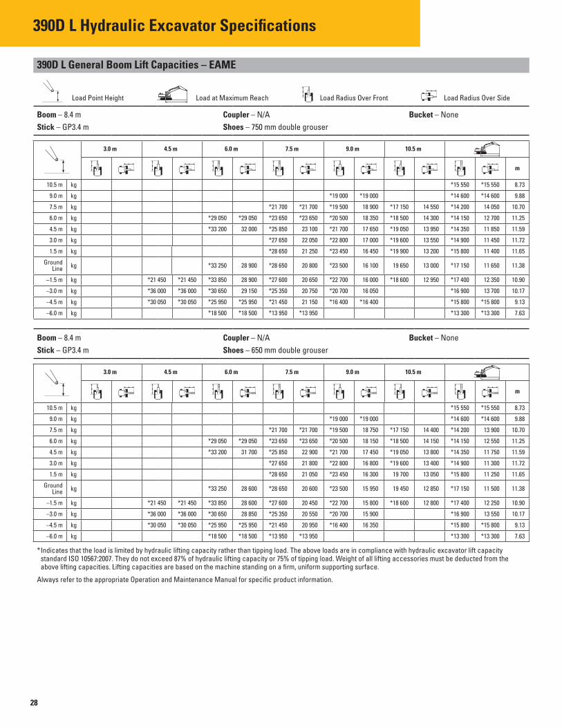
390D L General Boom Lift Capacities – EAME
Load Point Height Load at Maximum Reach Load Radius Over Front Load Radius Over Side
Boom – 8.4 m Coupler – N/A Bucket – None
Stick – GP3.4 m Shoes – 750 mm double grouser
3.0 m 4.5 m 6.0 m 7.5 m 9.0 m 10.5 m
m
10.5 m kg *15 550 *15 550 8.73
9.0 m kg *19 000 *19 000 *14 600 *14 600 9.88
7.5 m kg *21 700 *21 700 *19 500 18 900 *17 150 14 550 *14 200 14 050 10.70
6.0 m kg *29 050 *29 050 *23 650 *23 650 *20 500 18 350 *18 500 14 300 *14 150 12 700 11.25
4.5 m kg *33 200 32 000 *25 850 23 100 *21 700 17 650 *19 050 13 950 *14 350 11 850 11.59
3.0 m kg *27 650 22 050 *22 800 17 000 *19 600 13 550 *14 900 11 450 11.72
1.5 m kg *28 650 21 250 *23 450 16 450 *19 900 13 200 *15 800 11 400 11.65
Ground Line kg *33 250 28 900 *28 650 20 800 *23 500 16 100 19 650 13 000 *17 150 11 650 11.38
–1.5 m kg *21 450 *21 450 *33 850 28 900 *27 600 20 650 *22 700 16 000 *18 600 12 950 *17 400 12 350 10.90
–3.0 m kg *36 000 *36 000 *30 650 29 150 *25 350 20 750 *20 700 16 050 *16 900 13 700 10.17
–4.5 m kg *30 050 *30 050 *25 950 *25 950 *21 450 21 150 *16 400 *16 400 *15 800 *15 800 9.13
–6.0 m kg *18 500 *18 500 *13 950 *13 950 *13 300 *13 300 7.63
Boom – 8.4 m Coupler – N/A Bucket – None
Stick – GP3.4 m Shoes – 650 mm double grouser
3.0 m 4.5 m 6.0 m 7.5 m 9.0 m 10.5 m
m
10.5 m kg *15 550 *15 550 8.73
9.0 m kg *19 000 *19 000 *14 600 *14 600 9.88
7.5 m kg *21 700 *21 700 *19 500 18 750 *17 150 14 400 *14 200 13 900 10.70
6.0 m kg *29 050 *29 050 *23 650 *23 650 *20 500 18 150 *18 500 14 150 *14 150 12 550 11.25
4.5 m kg *33 200 31 700 *25 850 22 900 *21 700 17 450 *19 050 13 800 *14 350 11 750 11.59
3.0 m kg *27 650 21 800 *22 800 16 800 *19 600 13 400 *14 900 11 300 11.72
1.5 m kg *28 650 21 050 *23 450 16 300 19 700 13 050 *15 800 11 250 11.65
Ground Line kg *33 250 28 600 *28 650 20 600 *23 500 15 950 19 450 12 850 *17 150 11 500 11.38
–1.5 m kg *21 450 *21 450 *33 850 28 600 *27 600 20 450 *22 700 15 800 *18 600 12 800 *17 400 12 250 10.90
–3.0 m kg *36 000 *36 000 *30 650 28 850 *25 350 20 550 *20 700 15 900 *16 900 13 550 10.17
–4.5 m kg *30 050 *30 050 *25 950 *25 950 *21 450 20 950 *16 400 16 350 *15 800 *15 800 9.13
–6.0 m kg *18 500 *18 500 *13 950 *13 950 *13 300 *13 300 7.63
Indicates that the load is limited by hydraulic lifting capacity rather than tipping load. The above loads are in compliance with hydraulic excavator lift capacity * standard ISO 10567:2007. They do not exceed 87% of hydraulic lifting capacity or 75% of tipping load. Weight of all lifting accessories must be deducted from the above lifting capacities. Lifting capacities are based on the machine standing on a firm, uniform supporting surface.
Always refer to the appropriate Operation and Maintenance Manual for specific product information.

29
390D L General Boom Lift Capacities – EAME
Load Point Height Load at Maximum Reach Load Radius Over Front Load Radius Over Side
Boom – 8.4 m Coupler – N/A Bucket – None
Stick – GP2.92 m Shoes – 750 mm double grouser
3.0 m 4.5 m 6.0 m 7.5 m 9.0 m 10.5 m
m
10.5 m kg *21 400 *21 400 *17 650 *17 650 8.15
9.0 m kg *21 450 *21 450 *20 050 19 000 *16 450 *16 450 9.38
7.5 m kg *22 700 *22 700 *20 300 18 750 *15 900 15 000 10.23
6.0 m kg *30 550 *30 550 *24 600 24 050 *21 200 18 200 *19 150 14 200 *15 800 13 500 10.81
4.5 m kg *26 650 22 900 *22 300 17 550 *19 550 13 900 *16 050 12 600 11.16
3.0 m kg *28 250 21 900 *23 200 16 950 *19 950 13 550 *16 650 12 150 11.29
1.5 m kg *28 950 21 200 *23 700 16 450 19 950 13 250 *17 650 12 050 11.22
Ground Line kg *30 450 29 050 *28 550 20 900 *23 500 16 200 *19 550 13 100 *18 300 12 400 10.95
–1.5 m kg *32 700 29 150 *27 150 20 800 *22 350 16 100 *18 000 13 250 10.44
–3.0 m kg *32 750 *32 750 *29 200 *29 200 *24 450 21 000 *19 850 16 300 *17 300 14 900 9.68
–4.5 m kg *26 750 *26 750 *23 950 *23 950 *19 850 *19 850 *15 750 *15 750 8.58
Boom – 8.4 m Coupler – N/A Bucket – None
Stick – GP2.92 m Shoes – 650 mm double grouser
3.0 m 4.5 m 6.0 m 7.5 m 9.0 m 10.5 m
m
10.5 m kg *21 400 *21 400 *17 650 *17 650 8.15
9.0 m kg *21 450 *21 450 *20 050 18 850 *16 450 *16 450 9.38
7.5 m kg *22 700 *22 700 *20 300 18 550 *15 900 14 900 10.23
6.0 m kg *30 550 *30 550 *24 600 23 850 *21 200 18 000 *19 150 14 050 *15 800 13 350 10.81
4.5 m kg *26 650 22 650 *22 300 17 350 *19 550 13 750 *16 050 12 450 11.16
3.0 m kg *28 250 21 650 *23 200 16 750 *19 950 13 400 *16 650 12 000 11.29
1.5 m kg *28 950 21 000 *23 700 16 300 19 700 13 100 *17 650 11 950 11.22
Ground Line kg *30 450 28 750 *28 550 20 650 *23 500 16 000 *19 550 12 950 *18 300 12 300 10.95
–1.5 m kg *32 700 28 850 *27 150 20 600 *22 350 15 950 *18 000 13 100 10.44
–3.0 m kg *32 750 *32 750 *29 200 29 200 *24 450 20 800 *19 850 16 100 *17 300 14 700 9.68
–4.5 m kg *26 750 *26 750 *23 950 *23 950 *19 850 *19 850 *15 750 *15 750 8.58
Indicates that the load is limited by hydraulic lifting capacity rather than tipping load. The above loads are in compliance with hydraulic excavator lift capacity * standard ISO 10567:2007. They do not exceed 87% of hydraulic lifting capacity or 75% of tipping load. Weight of all lifting accessories must be deducted from the above lifting capacities. Lifting capacities are based on the machine standing on a firm, uniform supporting surface.
Always refer to the appropriate Operation and Maintenance Manual for specific product information.

30
390D L Hydraulic Excavator Specifi cations
390D L Mass Boom Lift Capacities – EAME
Load Point Height Load at Maximum Reach Load Radius Over Front Load Radius Over Side
Boom – 7.25 m Coupler – N/A Bucket – None
Stick – M3.4 m Shoes – 750 mm double grouser
3.0 m 4.5 m 6.0 m 7.5 m 9.0 m
m
10.5 m kg *17 400 *17 400 6.96
9.0 m kg *21 650 *21 650 *15 900 *15 900 8.36
7.5 m kg *23 500 *23 500 *18 950 *18 950 *15 350 *15 350 9.32
6.0 m kg *29 350 *29 350 *24 900 *24 900 *22 200 18 650 *15 250 *15 250 9.95
4.5 m kg *45 600 *45 600 *33 050 *33 050 *26 800 24 050 *23 000 18 150 *15 600 14 500 10.33
3.0 m kg *36 200 32 100 *28 500 23 050 *23 850 17 550 *16 350 13 950 10.47
1.5 m kg *37 700 30 800 *29 500 22 200 *24 250 17 100 *17 600 13 850 10.40
Ground Line kg *27 950 *27 950 *37 150 30 100 *29 300 21 700 *23 800 16 750 *19 550 14 300 10.10
–1.5 m kg *23 550 *23 550 *41 700 *41 700 *34 700 29 950 *27 650 21 500 *22 000 16 650 *19 800 15 400 9.55
–3.0 m kg *38 700 *38 700 *37 000 *37 000 *30 150 *30 150 *24 000 21 650 *18 800 17 700 8.70
–4.5 m kg *27 250 *27 250 *22 550 *22 550 *16 350 *16 350 7.46
Boom – 7.25 m Coupler – N/A Bucket – None
Stick – M3.4 m Shoes – 650 mm double grouser
3.0 m 4.5 m 6.0 m 7.5 m 9.0 m
m
10.5 m kg *17 400 *17 400 6.96
9.0 m kg *21 650 *21 650 *15 900 *15 900 8.36
7.5 m kg *23 500 *23 500 *18 950 18 850 *15 350 *15 350 9.32
6.0 m kg *29 350 *29 350 *24 900 24 850 *22 200 18 500 *15 250 *15 250 9.95
4.5 m kg *45 600 *45 600 *33 050 *33 050 *26 800 23 850 *23 000 17 950 *15 600 14 400 10.33
3.0 m kg *36 200 31 800 *28 500 22 800 *23 850 17 400 *16 350 13 800 10.47
1.5 m kg *37 700 30 500 *29 500 22 000 *24 250 16 900 *17 600 13 700 10.40
Ground Line kg *27 950 *27 950 *37 150 29 800 *29 300 21 450 *23 800 16 600 *19 550 14 150 10.10
–1.5 m kg *23 550 *23 550 *41 700 *41 700 *34 700 29 650 *27 650 21 300 *22 000 16 500 *19 800 15 250 9.55
–3.0 m kg *38 700 *38 700 *37 000 *37 000 *30 150 29 850 *24 000 21 450 *18 800 17 500 8.70
–4.5 m kg *27 250 *27 250 *22 550 *22 550 *16 350 *16 350 7.46
Indicates that the load is limited by hydraulic lifting capacity rather than tipping load. The above loads are in compliance with hydraulic excavator lift capacity * standard ISO 10567:2007. They do not exceed 87% of hydraulic lifting capacity or 75% of tipping load. Weight of all lifting accessories must be deducted from the above lifting capacities. Lifting capacities are based on the machine standing on a firm, uniform supporting surface.
Always refer to the appropriate Operation and Maintenance Manual for specific product information.
31
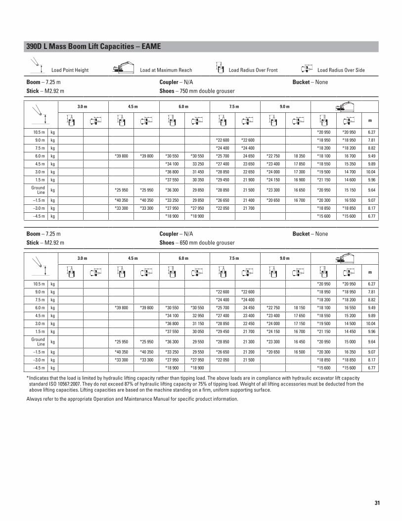
390D L Mass Boom Lift Capacities – EAME
Load Point Height Load at Maximum Reach Load Radius Over Front Load Radius Over Side
Boom – 7.25 m Coupler – N/A Bucket – None
Stick – M2.92 m Shoes – 750 mm double grouser
3.0 m 4.5 m 6.0 m 7.5 m 9.0 m
m
10.5 m kg *20 950 *20 950 6.27
9.0 m kg *22 600 *22 600 *18 950 *18 950 7.81
7.5 m kg *24 400 *24 400 *18 200 *18 200 8.82
6.0 m kg *39 800 *39 800 *30 550 *30 550 *25 700 24 650 *22 750 18 350 *18 100 16 700 9.49
4.5 m kg *34 100 33 250 *27 400 23 650 *23 400 17 850 *18 550 15 350 9.89
3.0 m kg *36 800 31 450 *28 850 22 650 *24 000 17 300 *19 500 14 700 10.04
1.5 m kg *37 550 30 350 *29 450 21 900 *24 150 16 900 *21 150 14 600 9.96
Ground Line kg *25 950 *25 950 *36 300 29 850 *28 850 21 500 *23 300 16 650 *20 950 15 150 9.64
–1.5 m kg *40 350 *40 350 *33 250 29 850 *26 650 21 400 *20 650 16 700 *20 300 16 550 9.07
–3.0 m kg *33 300 *33 300 *27 950 *27 950 *22 050 21 700 *18 850 *18 850 8.17
–4.5 m kg *18 900 *18 900 *15 600 *15 600 6.77
Boom – 7.25 m Coupler – N/A Bucket – None
Stick – M2.92 m Shoes – 650 mm double grouser
3.0 m 4.5 m 6.0 m 7.5 m 9.0 m
m
10.5 m kg *20 950 *20 950 6.27
9.0 m kg *22 600 *22 600 *18 950 *18 950 7.81
7.5 m kg *24 400 *24 400 *18 200 *18 200 8.82
6.0 m kg *39 800 *39 800 *30 550 *30 550 *25 700 24 450 *22 750 18 150 *18 100 16 550 9.49
4.5 m kg *34 100 32 950 *27 400 23 400 *23 400 17 650 *18 550 15 200 9.89
3.0 m kg *36 800 31 150 *28 850 22 450 *24 000 17 150 *19 500 14 500 10.04
1.5 m kg *37 550 30 050 *29 450 21 700 *24 150 16 700 *21 150 14 450 9.96
Ground Line kg *25 950 *25 950 *36 300 29 550 *28 850 21 300 *23 300 16 450 *20 950 15 000 9.64
–1.5 m kg *40 350 *40 350 *33 250 29 550 *26 650 21 200 *20 650 16 500 *20 300 16 350 9.07
–3.0 m kg *33 300 *33 300 *27 950 *27 950 *22 050 21 500 *18 850 *18 850 8.17
–4.5 m kg *18 900 *18 900 *15 600 *15 600 6.77
Indicates that the load is limited by hydraulic lifting capacity rather than tipping load. The above loads are in compliance with hydraulic excavator lift capacity * standard ISO 10567:2007. They do not exceed 87% of hydraulic lifting capacity or 75% of tipping load. Weight of all lifting accessories must be deducted from the above lifting capacities. Lifting capacities are based on the machine standing on a firm, uniform supporting surface.
Always refer to the appropriate Operation and Maintenance Manual for specific product information.
32
390D L Standard Equipment
ELECTRICALAlternator – 75 ampLights: Cab interiorSignal/warning hornPower supply at battery compartment – 24V
ENGINE/POWER TRAINAutomatic engine speed controlAutomatic swing parking brakeAutomatic travel parking brakesCat® C18 engine with ACERT™ Technology
Altitude capability to 2300 m without derating
High ambient cooling, 52° C capabilitySide-by-side cooling system
with separately mounted AC condenser and variable speed fan
Two speed travelWater separator
with level indicator for fuel lineElectric fuel priming pump
GUARDSHeavy-duty travel motor guards
on upper frameHeavy-duty swivel guard on undercarriageHeavy-duty travel motor guards
on undercarriage
OPERATOR STATIONAir conditioner, heater and defroster
with automatic climate controlAshtray and 24V lighterBeverage/cup holderCoat hookConsole-mounted, electronic-type joysticks
with adjustable gain and responseFloor matInstrument panel and gauges
with full color graphical displayLiterature compartmentNeutral lever (lock-out) for all controlsPositive fi ltered ventilationPressurized cabRetractable seat belt, 75 mm wideStationary skylight (polycarbonate)Sunshade for windshield and skylightTravel control pedals
with removable hand leversWindshield wipers and washers
(upper and lower)
UNDERCARRIAGEGrease lubricated and positive pin
retention trackHydraulic track adjustersLong, variable gaugeSteps, four
OTHER STANDARD EQUIPMENTAuxiliary hydraulic valve
for hydro-mechanical toolsCat® one key security system
with locks for doors, cab and fuel capCatwalks, left and right sidesCrossroller-type swing bearingDrive for auxiliary pumpHand control pattern changerMirrors, left and rightS·O·SSM quick sampling valves
for engine oil and hydraulic oilSteel fi rewall between engine
and hydraulic pumpsWiring provisions for Cat® Product Link,
AutoLube System and lighted beacon
Standard equipment may vary. Consult your Cat dealer for details.

33
390D L Optional Equipment
FRONT LINKAGEBucket linkagesVB family for VB sticks
(available with or without lifting eye)WB family for WB sticks
(available with or without lifting eye)Buckets – see chartsBooms (with two working lights)
Mass Excavation – 7250 mmReach – 10 000 mmGP – 8400 mm
SticksFor Mass Boom
• M2.92JC• M3.4JC
For Reach Boom• R5.5HB2• R4.4HB2
For GP Boom• R5.5HB2• R4.4HB2• GP3.4JC• GP2.92JC
Tips, sidecutters and edge protectors
TRACKDouble grouser, heavy duty
• 650 mm• 750 mm• 900 mm
GUARDSFOGS (Falling Object Guard System)
including overhead and windshield guardsTrack guiding guards
• Full length• Center section
Wire mesh screen for windshieldAuxiliary controls and lines
Auxiliary boom lines (high pressure for reach and mass booms)
Auxiliary stick lines (high pressure for reach and mass booms)
Basic control arrangements:• Single action – one way, high-pressure
circuit for hammer application• Combined function – one way, high-
pressure circuit for hammer application function for one-way or two-way high pressure
MISCELLANEOUS OPTIONSBoom lowering control device
with SmartBoom™Cab front rain protectorConverters, 7 amp-12V (two)Electric refueling pumpFine fi ltration fi lterJump start terminalsReversible cooling fan
including protective screenStarting aid with ether for cold weather Stick lowering control deviceTravel alarm with cut-off switch
OPERATOR COMPARTMENTJoysticks
Four button joystick for standard machine or single action auxiliary control
Thumb wheel modulation joystick for use with combined auxiliary control
Lunch box storage with lidMachine Security System
with programmable keysRadio
AM/FM radio-mounted in right console with antenna and two speakers
Radio-ready mounting at rear location including 24V to 12V converter, speakers, antenna
SeatAdjustable, high back
with mechanical suspensionAdjustable, high back
with air suspensionAdjustable, high back heated
with air suspensionStraight travel pedalWindshieldOne-piece, standard duty70-30 split, sliding
Optional equipment may vary. Consult your Cat dealer for details.

34
Notes

35
36
For more complete information on Cat products, dealer services, and industry solutions, visit us on the web at www.cat.com
© 2010 Caterpillar Inc.
All rights reserved
Materials and specifi cations are subject to change without notice. Featured machines in photos may include additional equipment. See your Cat dealer for available options.
CAT, CATERPILLAR, SAFETY.CAT.COM, their respective logos, “Caterpillar Yellow” and the “Power Edge” trade dress, as well as corporate and product identity used herein, are trademarks of Caterpillar and may not be used without permission.
390D L Hydraulic Excavator
HEHH4383-01 (09-2010)
Related Documents