Heateflex ® In-Line Heater Series Instruction Manual

Welcome message from author
This document is posted to help you gain knowledge. Please leave a comment to let me know what you think about it! Share it to your friends and learn new things together.
Transcript
Heateflex®
In-Line Heater SeriesInstruction Manual
Heateflex®
In-Line Heater SeriesInstruction Manual
While the official language of the "Original Instructions" is in English, any interpretation of this Instruction Manual in other Community languages will be discussed by the manufacturer (Heateflex Corporation) and the customer on a as required basis.
INTRODUCTION
Your Heateflex Corporation In-Line fluid heating system is a point of use heater that will accurately heat and maintain the temperature of your process fluid through the use of patented Heateflex® heating coil and Power-To-Flow Control® heating technologies. To obtain the best results from your unit, it is recommended that the user operating this system and the installer of this system completely read this manual and the accompanying component literature to become familiar with all the functions and features of the system.
DESCRIPTION
Your heating system is an electric heating system designed to be used in an ultra-high purity environment. It is a high tech piece of equipment incorporating many design innovations and precautionary measures to insure safe and reliable operation under normal conditions. This heating system incorporates features that enable it to be used with aggressive fluids, such as de-ionized water or acids, and maintain the purity of those process fluids. The safety systems used on the unit incorporate over-temperature protection, low liquid level protection, over-current protection, electrical component over-temperature protection, and a user-controlled emergency disconnect switch. These safeties combined with proven ultra pure technology provide a unit that effectively reaches and maintains process temperature. The construction of the fluid handling components of this unit use chemically resistant fluoro-plastics such as listed on next page.
HEATEFLEX® IN-LINE HEATERS
405 East Santa Clara Street, Arcadia, CA 91006-7227, U.S.A Tel: (626) 599-8566 Fax: (626) 599-9567 www.heateflex.com
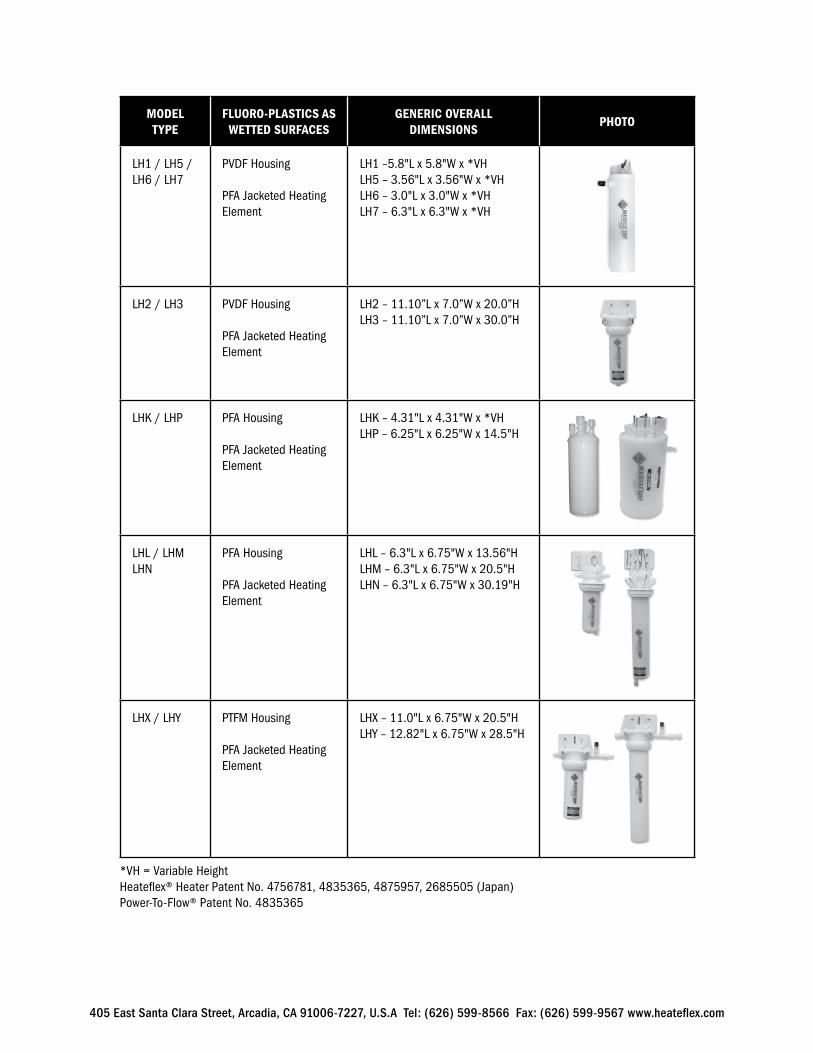
MODEL TYPE
FLUORO-PLASTICS AS WETTED SURFACES
GENERIC OVERALLDIMENSIONS
PHOTO
LH1 / LH5 / LH6 / LH7
PVDF Housing
PFA Jacketed Heating Element
LH1 –5.8"L x 5.8"W x *VH LH5 – 3.56"L x 3.56"W x *VHLH6 – 3.0"L x 3.0"W x *VHLH7 – 6.3"L x 6.3"W x *VH
LH2 / LH3 PVDF Housing
PFA Jacketed Heating Element
LH2 – 11.10”L x 7.0”W x 20.0”HLH3 – 11.10”L x 7.0”W x 30.0”H
LHK / LHP PFA Housing
PFA Jacketed Heating Element
LHK – 4.31"L x 4.31"W x *VHLHP – 6.25"L x 6.25"W x 14.5"H
LHL / LHMLHN
PFA Housing
PFA Jacketed Heating Element
LHL – 6.3"L x 6.75"W x 13.56"HLHM – 6.3"L x 6.75"W x 20.5"HLHN – 6.3"L x 6.75"W x 30.19"H
LHX / LHY PTFM Housing
PFA Jacketed Heating Element
LHX – 11.0"L x 6.75"W x 20.5"HLHY – 12.82"L x 6.75"W x 28.5"H
*VH = Variable HeightHeateflex® Heater Patent No. 4756781, 4835365, 4875957, 2685505 (Japan)Power-To-Flow® Patent No. 4835365
405 East Santa Clara Street, Arcadia, CA 91006-7227, U.S.A Tel: (626) 599-8566 Fax: (626) 599-9567 www.heateflex.com
This shipment was carefully inspected, checked, and properly packaged at our company, and delivered to the carrier in good condition. We fully expect your merchandise to arrive in your hands in good condition.
ALL PRODUCTS ARE SHIPPED F.O.B. FACTORY; THEREFORE, WHEN IT IS DELIVERED TO THE CARRIER, IT BECOMES YOUR PROPERTY. THUS, IT IS IMPORTANT THAT YOU TAKE NOTE OF ANY DAMAGE, WHETHER OBVIOUS OR HIDDEN, AND REPORT SAME TO THE TRANSPORTATION COMPANY WITHIN FIVE (5) DAYS OF RECEIPT OF THE SHIPMENT AT YOUR PREMISE TO AVOID FORFEITING CLAIMS FOR DAMAGE.
HERE IS WHAT TO DO IF YOUR SHIPMENT IS DAMAGED:
Leave the items, packing material, and carton “as is”. Notify your carrier’s local office and ask for immediate inspection of the carton and its content.
After inspection has been made by the carrier, and you have received acknowledgment in writing as to the damage, please contact our Customer Service Department at (626) 599-8566 for return authorization. If writing for return authorization, please indicate your purchase order number.
We will either repair or replace the merchandise depending upon the extent of the damage.
It is your responsibility to follow the above instructions, or the carrier will not honor any claims for damage. If there are any shortages or questions regarding this shipment, please notify us within ten (10) days.
RECEIVING INSPECTION PROCEDURE
405 East Santa Clara Street, Arcadia, CA 91006-7227, U.S.A Tel: (626) 599-8566 Fax: (626) 599-9567 www.heateflex.com
Every effort has been made to insure that this unit will run with a minimum of user input or maintenance. However, there are still precautions to be taken whenever operating, performing maintenance, or servicing this unit. This unit makes use of heating elements and electrical components, both of which pose inherent burn, fire, and electrical shock hazards. These hazards can result in injury to personnel, plant, and/or process. Please note the following to aid in the operation of your unit and to decrease risk of the above-mentioned hazards.
PRECAUTIONS:
• Carefully and completely read this and all accompanying literature to verify that you understand the functionality and features of this system. Please become familiar with the integral safeties and controls within this system, and know their function.
• Always disconnect electrical power prior to installing, servicing or replacing electric heating elements and/or assemblies.
• Electrical termination enclosures should be selected to match the application’s environment and be able to withstand worst-case failures, especially in hazardous locations.
• Avoid fire hazards. Electric heaters and their components can develop temperatures that produce an auto-ignition source. Avoid mounting heaters in atmospheres containing combustible gases, vapor or dust. Article 501 of the National Electrical Code (NEC) requires that the maximum sheath temperature when the heater is continually energized not exceed 80 percent of the surrounding atmosphere’s auto-ignition temperature.
• Avoid exposing heaters to combustible materials. Keep heaters far away from combustible materials to prevent ignition.
• Be aware of labeling on the unit, such as a lightning-bolt warning symbol, which alerts you to a safety hazard, which could harm you or the unit.
BASIC SAFETY PRECAUTIONS
405 East Santa Clara Street, Arcadia, CA 91006-7227, U.S.A Tel: (626) 599-8566 Fax: (626) 599-9567 www.heateflex.com
• While servicing or operating this unit, it is advisable to remove all metal from your person. This includes metal bracelets, rings, jewelry, metal-rimmed glasses, and wristwatches.
• Keep your clothing, hands, and feet dry at all times whenever working with electrical equipment.
• Pull the fuses, open the circuit breakers, or disconnect the circuits from their source of power to protect yourself, the test equipment and the equipment under test.
• Do not trouble shoot or service a circuit with the primary power applied.
• If it becomes necessary to work on the unit with the power applied, keep one hand free at all times (behind you).
• Be certain that there is no power applied to a circuit when making continuity or resistance checks.
• Use the correct tool (i.e. screwdriver, alignment tool, etc.) for the job.
• Do not use metal tools around the connectors when there is power to the unit, as they may cause arcing.
• Turn off power before connecting alligator clips to any circuit.
• Do not take anything for granted when working with inexperienced help. Check every operation before they perform it.
• The operation of this unit creates large amounts of heated process fluid. This fluid is likely to be heated to temperatures above the threshold of safety for human contact. Please be advised of this and take the necessary precautions whenever connecting or disconnecting any plumbing from the system. If you are ever in doubt, turn the unit off, and wait an appropriate amount of time before performing any operations or service involving the plumbing.
BASIC SAFETY PRECAUTIONS
405 East Santa Clara Street, Arcadia, CA 91006-7227, U.S.A Tel: (626) 599-8566 Fax: (626) 599-9567 www.heateflex.com
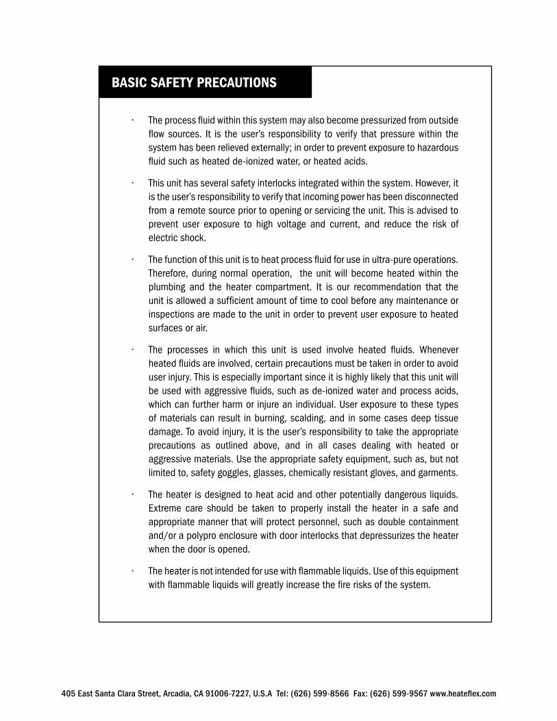
• The process fluid within this system may also become pressurized from outside flow sources. It is the user’s responsibility to verify that pressure within the system has been relieved externally; in order to prevent exposure to hazardous fluid such as heated de-ionized water, or heated acids.
• This unit has several safety interlocks integrated within the system. However, it is the user’s responsibility to verify that incoming power has been disconnected from a remote source prior to opening or servicing the unit. This is advised to prevent user exposure to high voltage and current, and reduce the risk of electric shock.
• The function of this unit is to heat process fluid for use in ultra-pure operations. Therefore, during normal operation, the unit will become heated within the plumbing and the heater compartment. It is our recommendation that the unit is allowed a sufficient amount of time to cool before any maintenance or inspections are made to the unit in order to prevent user exposure to heated surfaces or air.
• The processes in which this unit is used involve heated fluids. Whenever heated fluids are involved, certain precautions must be taken in order to avoid user injury. This is especially important since it is highly likely that this unit will be used with aggressive fluids, such as de-ionized water and process acids, which can further harm or injure an individual. User exposure to these types of materials can result in burning, scalding, and in some cases deep tissue damage. To avoid injury, it is the user’s responsibility to take the appropriate precautions as outlined above, and in all cases dealing with heated or aggressive materials. Use the appropriate safety equipment, such as, but not limited to, safety goggles, glasses, chemically resistant gloves, and garments.
• The heater is designed to heat acid and other potentially dangerous liquids. Extreme care should be taken to properly install the heater in a safe and appropriate manner that will protect personnel, such as double containment and/or a polypro enclosure with door interlocks that depressurizes the heater when the door is opened.
• The heater is not intended for use with flammable liquids. Use of this equipment with flammable liquids will greatly increase the fire risks of the system.
BASIC SAFETY PRECAUTIONS
405 East Santa Clara Street, Arcadia, CA 91006-7227, U.S.A Tel: (626) 599-8566 Fax: (626) 599-9567 www.heateflex.com
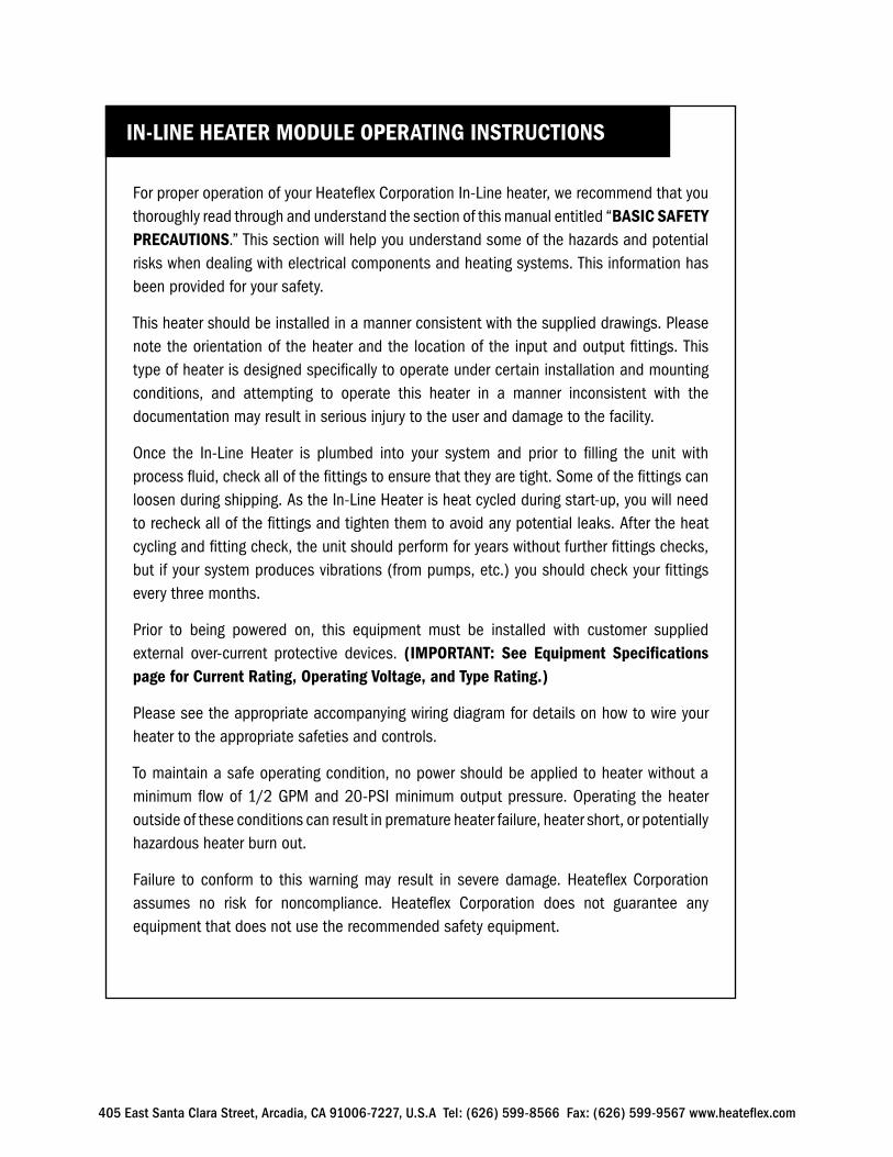
For proper operation of your Heateflex Corporation In-Line heater, we recommend that you thoroughly read through and understand the section of this manual entitled “BASIC SAFETY PRECAUTIONS.” This section will help you understand some of the hazards and potential risks when dealing with electrical components and heating systems. This information has been provided for your safety.
This heater should be installed in a manner consistent with the supplied drawings. Please note the orientation of the heater and the location of the input and output fittings. This type of heater is designed specifically to operate under certain installation and mounting conditions, and attempting to operate this heater in a manner inconsistent with the documentation may result in serious injury to the user and damage to the facility.
Once the In-Line Heater is plumbed into your system and prior to filling the unit with process fluid, check all of the fittings to ensure that they are tight. Some of the fittings can loosen during shipping. As the In-Line Heater is heat cycled during start-up, you will need to recheck all of the fittings and tighten them to avoid any potential leaks. After the heat cycling and fitting check, the unit should perform for years without further fittings checks, but if your system produces vibrations (from pumps, etc.) you should check your fittings every three months.
Prior to being powered on, this equipment must be installed with customer supplied external over-current protective devices. (IMPORTANT: See Equipment Specifications page for Current Rating, Operating Voltage, and Type Rating.)
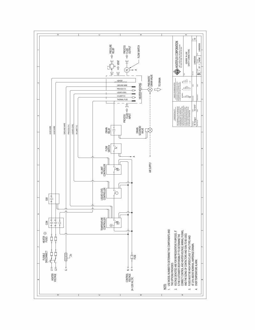
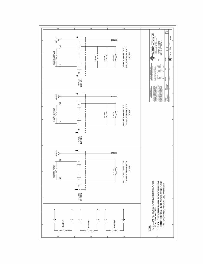
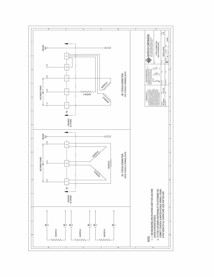
Please see the appropriate accompanying wiring diagram for details on how to wire your heater to the appropriate safeties and controls.
To maintain a safe operating condition, no power should be applied to heater without a minimum flow of 1/2 GPM and 20-PSI minimum output pressure. Operating the heater outside of these conditions can result in premature heater failure, heater short, or potentially hazardous heater burn out.
Failure to conform to this warning may result in severe damage. Heateflex Corporation assumes no risk for noncompliance. Heateflex Corporation does not guarantee any equipment that does not use the recommended safety equipment.
IN-LINE HEATER MODULE OPERATING INSTRUCTIONS
405 East Santa Clara Street, Arcadia, CA 91006-7227, U.S.A Tel: (626) 599-8566 Fax: (626) 599-9567 www.heateflex.com
WARNING & SAFETY
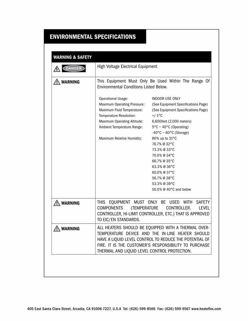
h DANGER High Voltage Electrical Equipment
i WARNING This Equipment Must Only Be Used Within The Range Of Environmental Conditions Listed Below.
Operational Usage: INDOOR USE ONLYMaximum Operating Pressure: (See Equipment Specifications Page)Maximum Fluid Temperature: (See Equipment Specifications Page)Temperature Resolution: +/-1°CMaximum Operating Altitude: 6,600feet (2,000 meters)Ambient Temperature Range: 5°C ~ 40°C (Operating) -40°C ~ 60°C (Storage)Maximum Relative Humidity: 80% up to 31°C 76.7% @ 32°C 73.3% @ 33°C 70.0% @ 34°C 66.7% @ 35°C 63.3% @ 36°C 60.0% @ 37°C 56.7% @ 38°C 53.3% @ 39°C 50.0% @ 40°C and below
i WARNING THIS EQUIPMENT MUST ONLY BE USED WITH SAFETY COMPONENTS (TEMPERATURE CONTROLLER, LEVEL CONTROLLER, HI-LIMIT CONTROLLER, ETC.) THAT IS APPROVED TO EIC/EN STANDARDS.
i WARNING ALL HEATERS SHOULD BE EQUIPPED WITH A THERMAL OVER-TEMPERATURE DEVICE AND THE IN-LINE HEATER SHOULD HAVE A LIQUID LEVEL CONTROL TO REDUCE THE POTENTIAL OF FIRE. IT IS THE CUSTOMER’S RESPONSIBILITY TO PURCHASE THERMAL AND LIQUID LEVEL CONTROL PROTECTION.
ENVIRONMENTAL SPECIFICATIONS
405 East Santa Clara Street, Arcadia, CA 91006-7227, U.S.A Tel: (626) 599-8566 Fax: (626) 599-9567 www.heateflex.com
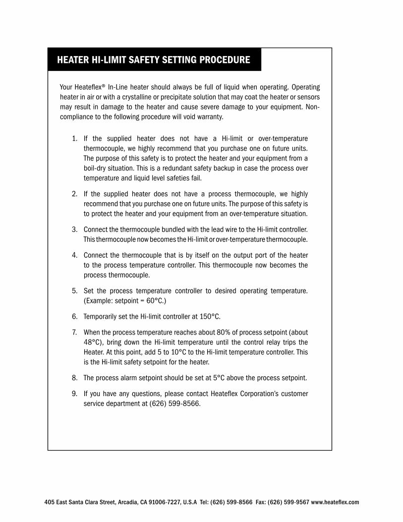
Your Heateflex® In-Line heater should always be full of liquid when operating. Operating heater in air or with a crystalline or precipitate solution that may coat the heater or sensors may result in damage to the heater and cause severe damage to your equipment. Non- compliance to the following procedure will void warranty.
1. If the supplied heater does not have a Hi-limit or over-temperature thermocouple, we highly recommend that you purchase one on future units. The purpose of this safety is to protect the heater and your equipment from a boil-dry situation. This is a redundant safety backup in case the process over temperature and liquid level safeties fail.
2. If the supplied heater does not have a process thermocouple, we highly recommend that you purchase one on future units. The purpose of this safety is to protect the heater and your equipment from an over-temperature situation.
3. Connect the thermocouple bundled with the lead wire to the Hi-limit controller. This thermocouple now becomes the Hi-limit or over-temperature thermocouple.
4. Connect the thermocouple that is by itself on the output port of the heater to the process temperature controller. This thermocouple now becomes the process thermocouple.
5. Set the process temperature controller to desired operating temperature. (Example: setpoint = 60°C.)
6. Temporarily set the Hi-limit controller at 150°C.
7. When the process temperature reaches about 80% of process setpoint (about 48°C), bring down the Hi-limit temperature until the control relay trips the Heater. At this point, add 5 to 10°C to the Hi-limit temperature controller. This is the Hi-limit safety setpoint for the heater.
8. The process alarm setpoint should be set at 5°C above the process setpoint.
9. If you have any questions, please contact Heateflex Corporation’s customer service department at (626) 599-8566.
HEATER HI-LIMIT SAFETY SETTING PROCEDURE
405 East Santa Clara Street, Arcadia, CA 91006-7227, U.S.A Tel: (626) 599-8566 Fax: (626) 599-9567 www.heateflex.com
405 East Santa Clara Street, Arcadia, CA 91006-7227, U.S.A Tel: (626) 599-8566 Fax: (626) 599-9567 www.heateflex.com
Heateflex is a registered trademark of Heateflex CorporationPower-To-Flow is a registered trademark of Heateflex CorporationPower-To-Flow Control is a registered trademark of Heateflex Corporation
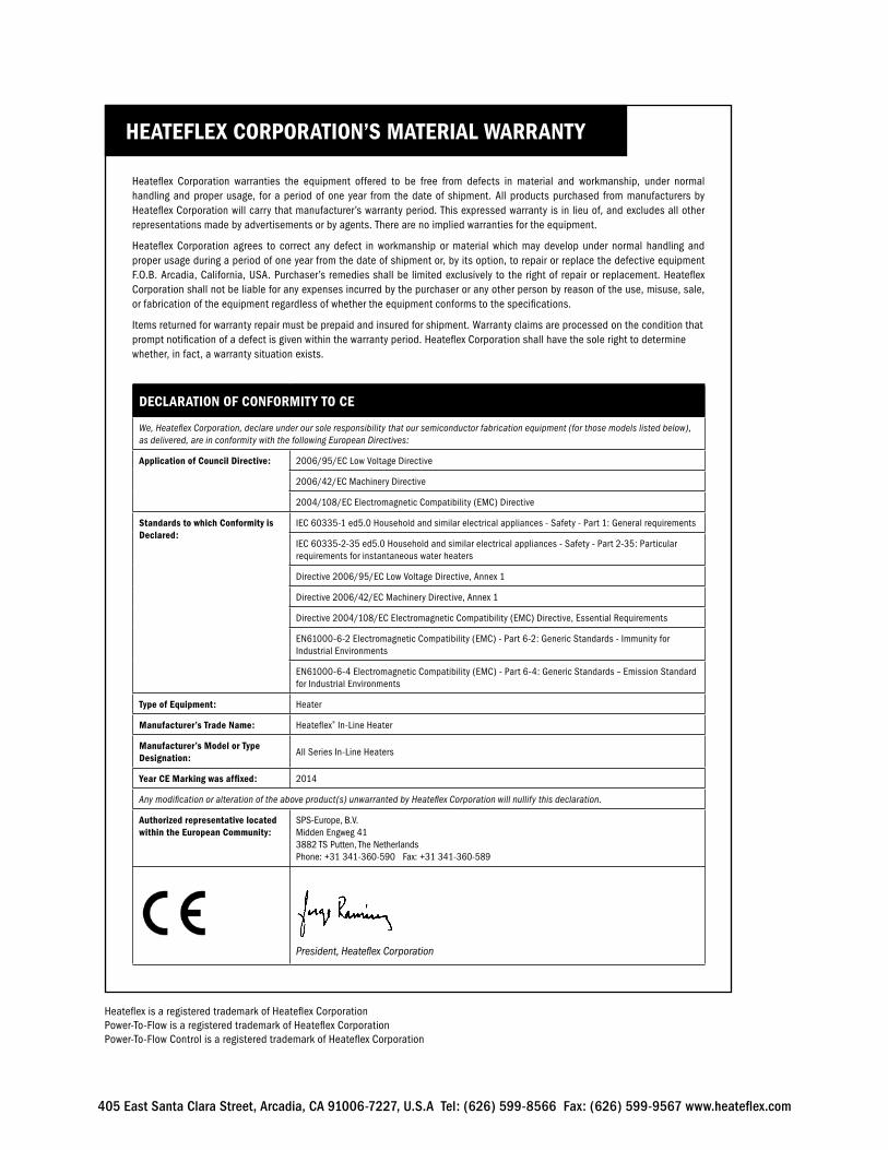
HEATEFLEX CORPORATION’S MATERIAL WARRANTY
Heateflex Corporation warranties the equipment offered to be free from defects in material and workmanship, under normal handling and proper usage, for a period of one year from the date of shipment. All products purchased from manufacturers by Heateflex Corporation will carry that manufacturer’s warranty period. This expressed warranty is in lieu of, and excludes all other representations made by advertisements or by agents. There are no implied warranties for the equipment.
Heateflex Corporation agrees to correct any defect in workmanship or material which may develop under normal handling and proper usage during a period of one year from the date of shipment or, by its option, to repair or replace the defective equipment F.O.B. Arcadia, California, USA. Purchaser’s remedies shall be limited exclusively to the right of repair or replacement. Heateflex Corporation shall not be liable for any expenses incurred by the purchaser or any other person by reason of the use, misuse, sale, or fabrication of the equipment regardless of whether the equipment conforms to the specifications.
Items returned for warranty repair must be prepaid and insured for shipment. Warranty claims are processed on the condition that prompt notification of a defect is given within the warranty period. Heateflex Corporation shall have the sole right to determine whether, in fact, a warranty situation exists.
DECLARATION OF CONFORMITY TO CE
We, Heateflex Corporation, declare under our sole responsibility that our semiconductor fabrication equipment (for those models listed below), as delivered, are in conformity with the following European Directives:
Application of Council Directive: 2006/95/EC Low Voltage Directive
2006/42/EC Machinery Directive
2004/108/EC Electromagnetic Compatibility (EMC) Directive
Standards to which Conformity is Declared:
IEC 60335-1 ed5.0 Household and similar electrical appliances - Safety - Part 1: General requirements
IEC 60335-2-35 ed5.0 Household and similar electrical appliances - Safety - Part 2-35: Particular requirements for instantaneous water heaters
Directive 2006/95/EC Low Voltage Directive, Annex 1
Directive 2006/42/EC Machinery Directive, Annex 1
Directive 2004/108/EC Electromagnetic Compatibility (EMC) Directive, Essential Requirements
EN61000-6-2 Electromagnetic Compatibility (EMC) - Part 6-2: Generic Standards - Immunity for Industrial Environments
EN61000-6-4 Electromagnetic Compatibility (EMC) - Part 6-4: Generic Standards – Emission Standard for Industrial Environments
Type of Equipment: Heater
Manufacturer’s Trade Name: Heateflex® In-Line Heater
Manufacturer’s Model or Type Designation:
All Series In-Line Heaters
Year CE Marking was affixed: 2014
Any modification or alteration of the above product(s) unwarranted by Heateflex Corporation will nullify this declaration.
Authorized representative located within the European Community:
SPS-Europe, B.V.Midden Engweg 413882 TS Putten, The NetherlandsPhone: +31 341-360-590 Fax: +31 341-360-589
President, Heateflex Corporation
L1 L2 G
L2
T2
L1
T1
CON
L1
T1
SSR
TO D
RAIN
AIR S
UPPL
Y
HEAT
ER H
OUSIN
G
HEATER
CONT
ROLL
ERTE
MPE
RATU
RECO
NTRO
LLER
LIQUI
D LE
VEL
CONT
ROLL
ERHI
-LIM
IT
SWITC
HFL
OWRE
LAY
DRAI
N
N HVO
LTAG
ECO
NTRO
L
24-1
20V A
C/DC
LEA
D W
IRE
LEA
D W
IRE
GRO
UN
D W
IRE
PRO
CESS
T/C
LIQ
UID
LEV
EL
HI-L
IMIT
T/C
VOLT
AGE
HEAT
ER
DISC
ONNE
CTFU
SIBLE
RELIE
FPR
ESSU
RE
FLUI
DPR
OCES
S
OUTP
UT
VENT
FLUI
DPR
OCES
S
INPU
T
THERMAL FUSE
HI-LIMIT T/C
LIQUID LEVEL
PROCESS T/C
GROUND WIRE
SOLE
NOID
DRAI
N
VALV
E
DRAI
N VA
LVE
PNEU
MATIC
FUSE
FS AA
FLOW
SWITC
H
FUSE
SHE
ATER
4
3
A
8
B
76
5
CD
87
65
DAT
E:D
ATE:
IN A
NY
MAN
NER
, NO
R U
SED
FO
R AN
YTR
ACED
, PHO
TOGR
APHE
D, R
EPRO
DUC
ED
UNLE
SS O
THER
WIS
E NO
TED
THIS
DRA
WIN
G &
TH
E IN
FORM
ATIO
N
CO
RPO
RATI
ON
AN
D M
AY N
OT
BE&
PRO
PRIE
TARY
TO
HEA
TEFL
EXCO
NTA
INED
TH
EREI
N IS
CO
NFI
DEN
TIAL
43
2
CON
FID
ENTI
ALI
TY
.XXX
XX/
XX
.XXX
.XX
DRA
WN
BY:
ENG
/DSG
N:
HEAT
EFLE
X COR
PORA
TION
TEL:
(626
) 599
-856
6 FA
X: (6
26) 5
99-9
567
1
405
E. S
ANTA
CLA
RA, A
RCAD
IA, C
A 91
006
DW
G. N
O.:
BSH
EET:
OF
TITL
E:
FILE
:SC
ALE
:
REV.
AB
43
2
C
1
D
FLUID
HEATIN
G
ULTRA PURE
DAT
E:A
PPRO
VED
BY
EXPR
ESS
WRI
TTEN
AU
THO
RIZA
TIO
NPU
RPO
SE W
HAT
SOEV
ER W
ITH
OU
T TH
E
DIM
ENSI
ON
S &
TOLE
REN
CIN
G A
RE IN
INCH
ES(M
illim
eter
s) &
PER
ANS
I-Y14
.5&
HEAT
EFLE
X CO
RP. D
RAFT
ING
STAN
DARD
S.
DECI
MAL
S:0.
25
0.01
270.
127
mm
0.01
0.00
5
1/32
0.00
05
in 0.5°
0.5°
-+
DRA
FTIN
G Q
C:D
ATE:
OF
HEA
TEFL
EX C
ORP
ORA
TIO
N.
+ - + - + - + -
+ - + - + - + -
00
LHW
00D0
0NO
NE1
1
10/1
0/07
LHW
00D0
0
GENE
RIC
IN-L
INE
SAFE
TY C
ONNE
CTIO
NS
M. T
iong
co
NOTE
:1.
USE M
ODEL
NUM
BER T
O DE
TERM
INE T
HE CO
MPO
NENT
S AND
TH
E OPT
IONS
PROV
IDED
.2.
VOLT
AGE D
ENOT
ED A
RE FO
R REP
RESE
NTAT
IVE PU
RPOS
ES. IT
IS
THE C
USTO
MER
'S RE
SPON
SIBILI
TY TO
DET
ERM
INE T
HE
CORR
ECT C
ONTR
OL A
ND H
EATE
R VOL
TAGE
, WIRI
NG, F
USIN
G,
AND
THE S
IZING
OF C
ONTA
CTOR
S AND
SSRs
TO BE
USE
D.3.
FUSE
S MUS
T BE H
IGH
SPEE
D/CL
ASS "
J" (H
SJ TY
PE) A
ND
AT 25
% AB
OVE N
OMIN
AL A
MPE
RAGE
DRA
WN.
4.OV
ER TE
MPE
RATU
RE A
LARM
.
HEAT
ER #
1
1 1BKBK
HEAT
ER #
2
2 2BKBK
HEAT
ER #
3
3 3BKBK
INCO
MIN
G PO
WER
VAC
L1L2
12
TB
1A
- TYP
ICAL
CO
NN
ECTI
ON
1-
PHAS
E @ TE
RMIN
AL B
LOCK
BY O
THER
SPR
OVID
ED
BUS
GROU
ND
HEAT
ER #1
INCO
MIN
G PO
WER
VAC
L1L2
12
TB
1B
- TYP
ICAL
CO
NN
ECTI
ON
1-
PHAS
E @ TE
RMIN
AL B
LOCK
BY O
THER
SPR
OVID
ED
BUS
GROU
ND
HEAT
ER #1
INCO
MIN
G PO
WER
VAC
L1L2
12
TB
1C
- TYP
ICAL
CO
NN
ECTI
ON
1-
PHAS
E @ TE
RMIN
AL B
LOCK
BY O
THER
SPR
OVID
ED
BUS
GROU
ND
HEAT
ER #1
HEAT
ER #2
HEAT
ER #2
HEAT
ER #3
1 HE
ATER
2 HE
ATER
S3
HEAT
ERS
A
8
B
76
5
CD
87
65
DAT
E:D
ATE:
IN A
NY
MAN
NER
, NO
R U
SED
FO
R AN
YTR
ACED
, PHO
TOGR
APHE
D, R
EPRO
DUC
ED
UNLE
SS O
THER
WIS
E NO
TED
THIS
DRA
WIN
G &
TH
E IN
FORM
ATIO
N
CO
RPO
RATI
ON
AN
D M
AY N
OT
BE&
PRO
PRIE
TARY
TO
HEA
TEFL
EXCO
NTA
INED
TH
EREI
N IS
CO
NFI
DEN
TIAL
43
2
CON
FID
ENTI
ALI
TY
.XXX
XX/
XX
.XXX
.XX
DRA
WN
BY:
ENG
/DSG
N:
HEAT
EFLE
X COR
PORA
TION
TEL:
(626
) 599
-856
6 FA
X: (6
26) 5
99-9
567
1
405
E. S
ANTA
CLA
RA, A
RCAD
IA, C
A 91
006
DW
G. N
O.:
BSH
EET:
OF
TITL
E:
FILE
:SC
ALE
:
REV.
AB
43
2
C
1
DFLU
ID H
EATING
ULTRA PURE
DAT
E:A
PPRO
VED
BY
EXPR
ESS
WRI
TTEN
AU
THO
RIZA
TIO
NPU
RPO
SE W
HAT
SOEV
ER W
ITH
OU
T TH
E
DIM
ENSI
ON
S &
TOLE
REN
CIN
G A
RE IN
INCH
ES(M
illim
eter
s) &
PER
ANS
I-Y14
.5&
HEAT
EFLE
X CO
RP. D
RAFT
ING
STAN
DARD
S.
DECI
MAL
S:0.
25
0.01
270.
127
mm
0.01
0.00
5
1/32
0.00
05
in 0.5°
0.5°
-+
DRA
FTIN
G Q
C:D
ATE:
OF
HEA
TEFL
EX C
ORP
ORA
TIO
N.
+ - + - + - + -
+ - + - + - + -
00
LH1P
HNO
NE1
1
10/1
5/07
LH1P
H
TYPI
CAL C
ONNE
CTIO
NFO
R 1-P
H HE
ATER
LEAD
S
M. T
iong
co
NOTE
S:
2.IT
IS TH
E CUS
TOM
ERS R
ESPO
NSIB
ILITY
TO D
ETER
MIN
E THE
& TH
E SIZ
ING
OF A
LL C
ONTA
CTOR
S USE
D FO
R THI
S UNI
T.CO
RREC
T CON
TROL
& H
EATE
R VOL
TAGE
, WIR
ING,
FUSI
NG
SEE E
NGIN
EERI
NG SP
ECIFI
CATIO
NS SH
EET F
OR LE
AD W
IRE
1.GA
UGE &
VOLT
AGE D
ETAI
LS.
INCO
MIN
G PO
WER
HEATER #1VAC
HEATER #2
HEATER #3
L1L3
L2
HEAT
ER #
3
HEAT
ER #
2
HEAT
ER #
1
1 1 2 2 3 3
BKBK BK BK BK BK
TB
3B
- TYP
ICAL
CO
NN
ECTI
ON
W
YE 3
-PHA
SE @
TERM
INAL
BLO
CK
12
34
5
N
INCO
MIN
G PO
WER
VAC
L1L3
L2
12
3TB
3A
- TYP
ICAL
CO
NN
ECTI
ON
DE
LTA
3-PH
ASE @
TERM
INAL
BLO
CK
BY O
THER
SPR
OVID
ED
BUS
GROU
ND
HEAT
ER #
3
HEATER #1
HEATER #2
BY O
THER
SPR
OVID
ED
BUS
GROU
ND
A
8
B
76
5
CD
87
65
DAT
E:D
ATE:
IN A
NY
MAN
NER
, NO
R U
SED
FO
R AN
YTR
ACED
, PHO
TOGR
APHE
D, R
EPRO
DUC
ED
UNLE
SS O
THER
WIS
E NO
TED
THIS
DRA
WIN
G &
TH
E IN
FORM
ATIO
N
CO
RPO
RATI
ON
AN
D M
AY N
OT
BE&
PRO
PRIE
TARY
TO
HEA
TEFL
EXCO
NTA
INED
TH
EREI
N IS
CO
NFI
DEN
TIAL
43
2
CON
FID
ENTI
ALI
TY
.XXX
XX/
XX
.XXX
.XX
DRA
WN
BY:
ENG
/DSG
N:
HEAT
EFLE
X COR
PORA
TION
TEL:
(626
) 599
-856
6 FA
X: (6
26) 5
99-9
567
1
405
E. S
ANTA
CLA
RA, A
RCAD
IA, C
A 91
006
DW
G. N
O.:
BSH
EET:
OF
TITL
E:
FILE
:SC
ALE
:
REV.
AB
43
2
C
1
D
FLUID
HEATIN
G
ULTRA PURE
DAT
E:A
PPRO
VED
BY
EXPR
ESS
WRI
TTEN
AU
THO
RIZA
TIO
NPU
RPO
SE W
HAT
SOEV
ER W
ITH
OU
T TH
E
DIM
ENSI
ON
S &
TOLE
REN
CIN
G A
RE IN
INCH
ES(M
illim
eter
s) &
PER
ANS
I-Y14
.5&
HEAT
EFLE
X CO
RP. D
RAFT
ING
STAN
DARD
S.
DECI
MAL
S:0.
25
0.01
270.
127
mm
0.01
0.00
5
1/32
0.00
05
in 0.5°
0.5°
-+
DRA
FTIN
G Q
C:D
ATE:
OF
HEA
TEFL
EX C
ORP
ORA
TIO
N.
+ - + - + - + -
+ - + - + - + -
00
LH3P
H1 :
11
1
10/1
5/07
INLIN
E 3-P
HASE
TYPI
CAL C
ONNE
CTIO
NFO
R 3-P
H HE
ATER
LEAD
S
M.Ti
ongc
o
NOTE
S:
2.IT
IS TH
E CUS
TOM
ERS R
ESPO
NSIB
ILITY
TO D
ETER
MIN
E THE
& TH
E SIZ
ING
OF A
LL C
ONTA
CTOR
S USE
D FO
R THI
S UNI
T.CO
RREC
T CON
TROL
& H
EATE
R VOL
TAGE
, WIR
ING,
FUSI
NG
SEE E
NGIN
EERI
NG SP
ECIFI
CATIO
NS SH
EET F
OR LE
AD W
IRE
1.GA
UGE &
VOLT
AGE D
ETAI
LS.
LH1000-2014
405 East Santa Clara Street, Arcadia, CA 91006-7227, U.S.A Tel: (626) 599-8566 Fax: (626) 599-9567 www.heateflex.com
Related Documents