339 The evolution of electrochemical, microstructural, and mechanical properties of aluminium alloy 2024-T4 (D16AT) during fatigue cycling S R Salimon 1 , A I Salimon 1 , and A M Korsunsky 2∗ 1 Moscow Institute of Steels and Alloys, Moscow, Russia 2 Department of Engineering Science, University of Oxford, Oxford, UK The manuscript was received on 15 July 2008 and was accepted after revision for publication on 21 September 2009. DOI: 10.1243/09544100JAERO423 Abstract: Coupons of fuselage skin made from the aluminium alloy D16AT (the Russian equivalent of 2024-Ò4) were obtained from several Russian TU-154 passenger aircraft after dif- ferent numbers of flight cycles and different lengths of operation. The coupons were subjected to electrochemical, microstructural, and mechanical testing with the aim of identifying any trends indicating fatigue damage accumulation and residual fatigue lifetime reduction during service. Alongside this investigation, laboratory fatigue test specimens were machined from the same alloy and subjected to cyclic fatigue loading to simulate the service conditions for the coupons. Electrochemical testing was used in order to determine the evolution of the corrosion potential of the near-surface layers. X-ray diffraction analysis was also carried out to characterize residual stress and texture evolution, while microstructural investigations were made using transmission electron microscopy (TEM), scanning electron microscopy (SEM), and secondary ion mass spec- troscopy. The suitability of using electrochemical, microscopic, and diffraction characterization methods for the detection of surface structural state modification and its connection with the mechanical performance of this alloy are discussed. Keywords: fatigue, corrosion, electrochemistry, ageing aircraft 1 INTRODUCTION In recent years, the problem of aircraft lifetime exten- sion has become the subject of much attention, owing to the increasing pressures on airline companies to provide ever greater amounts of passenger move- ment at price levels that continue to be pushed down by competition. The situation is particularly critical for developing countries and countries of the Newly Independent States. In many instances, economic dif- ficulties in these countries prevent them from buying newly built aircraft. This results in the ongoing use of the existing planes after periods approaching the origi- nal estimates of their safe operating lifetime. In Russia, about 80 per cent of civil aircraft are currently being flown at the 80–90 per cent lifetime level. Some smaller companies continue to exploit aircraft beyond their ∗ Corresponding author: Department of Engineering Science, University of Oxford, Parks Road, Oxford OX1 3PJ, UK. email: [email protected] normal operating lifetime. This extended use poses serious problems of ensuring flight reliability for civil air companies. In this situation, the methods of non-destructive damage diagnostics for aircraft structural materials assume great importance. In Russia, recent years have shown a sharp increase in the interest in the problems of assessing aeroplane ageing, and the development of methods for reliable and certifiable lifetime exten- sion. While the majority of passenger aircraft have seen 25–30 years of service, the likelihood of their replace- ment in the near future remains low. Airlines attempt to identify suitable guidelines for the extension of safe operating time, based on scientifically justified and verifiable grounds. The problem of identifying suitable criteria for estimating residual lifetime of aircraft can be sepa- rated into two specific sub-tasks, with characteristic methodologies. 1. Diagnostic procedures aimed at detecting major intolerable damages (internal cracks, ruptures, or JAERO423 Proc. IMechE Vol. 224 Part G: J. Aerospace Engineering

heat treatment of d16at
Nov 30, 2015
heat treament procedure for d16at alloy
Welcome message from author
This document is posted to help you gain knowledge. Please leave a comment to let me know what you think about it! Share it to your friends and learn new things together.
Transcript

339
The evolution of electrochemical, microstructural,and mechanical properties of aluminium alloy2024-T4 (D16AT) during fatigue cyclingS R Salimon1, A I Salimon1, and A M Korsunsky2∗1Moscow Institute of Steels and Alloys, Moscow, Russia2Department of Engineering Science, University of Oxford, Oxford, UK
The manuscript was received on 15 July 2008 and was accepted after revision for publication on 21 September 2009.
DOI: 10.1243/09544100JAERO423
Abstract: Coupons of fuselage skin made from the aluminium alloy D16AT (the Russianequivalent of 2024-Ò4) were obtained from several Russian TU-154 passenger aircraft after dif-ferent numbers of flight cycles and different lengths of operation. The coupons were subjected toelectrochemical, microstructural, and mechanical testing with the aim of identifying any trendsindicating fatigue damage accumulation and residual fatigue lifetime reduction during service.Alongside this investigation, laboratory fatigue test specimens were machined from the samealloy and subjected to cyclic fatigue loading to simulate the service conditions for the coupons.Electrochemical testing was used in order to determine the evolution of the corrosion potentialof the near-surface layers. X-ray diffraction analysis was also carried out to characterize residualstress and texture evolution, while microstructural investigations were made using transmissionelectron microscopy (TEM), scanning electron microscopy (SEM), and secondary ion mass spec-troscopy. The suitability of using electrochemical, microscopic, and diffraction characterizationmethods for the detection of surface structural state modification and its connection with themechanical performance of this alloy are discussed.
Keywords: fatigue, corrosion, electrochemistry, ageing aircraft
1 INTRODUCTION
In recent years, the problem of aircraft lifetime exten-sion has become the subject of much attention, owingto the increasing pressures on airline companies toprovide ever greater amounts of passenger move-ment at price levels that continue to be pushed downby competition. The situation is particularly criticalfor developing countries and countries of the NewlyIndependent States. In many instances, economic dif-ficulties in these countries prevent them from buyingnewly built aircraft. This results in the ongoing use ofthe existing planes after periods approaching the origi-nal estimates of their safe operating lifetime. In Russia,about 80 per cent of civil aircraft are currently beingflown at the 80–90 per cent lifetime level. Some smallercompanies continue to exploit aircraft beyond their
∗Corresponding author: Department of Engineering Science,
University of Oxford, Parks Road, Oxford OX1 3PJ, UK.
email: [email protected]
normal operating lifetime. This extended use posesserious problems of ensuring flight reliability for civilair companies.
In this situation, the methods of non-destructivedamage diagnostics for aircraft structural materialsassume great importance. In Russia, recent years haveshown a sharp increase in the interest in the problemsof assessing aeroplane ageing, and the developmentof methods for reliable and certifiable lifetime exten-sion.While the majority of passenger aircraft have seen25–30 years of service, the likelihood of their replace-ment in the near future remains low. Airlines attemptto identify suitable guidelines for the extension of safeoperating time, based on scientifically justified andverifiable grounds.
The problem of identifying suitable criteria forestimating residual lifetime of aircraft can be sepa-rated into two specific sub-tasks, with characteristicmethodologies.
1. Diagnostic procedures aimed at detecting majorintolerable damages (internal cracks, ruptures, or
JAERO423 Proc. IMechE Vol. 224 Part G: J. Aerospace Engineering

340 S R Salimon, A I Salimon, and A M Korsunsky
corrosion pits) during routine inspection betweenflights.
2. Complex integrated procedures for continuousnon-destructive monitoring of all elements andassemblies in an aeroplane, where the probabil-ity of intolerable damages emerging directly duringflight is high.
In the present study, the focus is on sub-task 2 in par-ticular. In order to develop and adopt this methodol-ogy, it has to be assumed that some reliable acceleratedtests may be devised that are capable of determiningstructural weaknesses, e.g. locations where dangerousfatigue cracks have appeared or may initiate in thetime between inspections. If such tests can be formu-lated and established, they would also provide power-ful tools for the estimation of safe residual lifetime.
The development of residual fatigue lifetime moni-toring tests must be based on some suitable modelsof cyclic evolutionary response to fatigue loadingin structural materials and components, at differentstructural levels (phase state, dislocation structure,grain ensemble, chemical inhomogeneity, electronsubsystem, etc.). However, it is notoriously difficultto construct a simple, but realistic, picture of fatigueresponse evolution, owing to the synergetic nature offatigue damage accumulation. As far as normal opera-tion in civil aviation over periods of several decadesis concerned, the conditions of service are particu-larly difficult to describe and simulate with adequatereliability. Indeed, in many cases complementaryinfluences must be considered of high- and low-cycle fatigue (HCF–LCF interaction), electrochemicalcorrosion and wear.
Nevertheless, arguments built on physically justi-fied assumptions may be put forward, and attemptsat their experimental verification be made. Disloca-tion activity in the very near-surface layers duringhigh-cycle fatigue for which there is extensive evi-dence (e.g. reference [1]) induces modifications ofthe surface layer structural state. Continuous gener-ation of high dislocation densities within microscopicvolumes localized near the surface affects the char-acter of alloy–environment interaction, which resultsin changes of the surface chemical state. Similarly,grain-level plasticity results in a complex evolution ofintergranular stresses, characterized by the repeatedstages of stress accumulation and relaxation, andeventual loss of continuity, crack initiation and fail-ure. These processes can be detected with the aid ofX-ray diffraction pattern analysis, which allows oneto extract information about orientation and grain-group-specific microstresses and microstrains, andtexture development.
The aluminium alloy 2024-T4 (D16AT in the Russiannomenclature) was chosen as a representative air-craft structural material for the present research. Thisalloy is widely used for various aeroplane components,
such as fuselage skin and flanks. In order to identifya suitably sensitive technique for accelerated tests, avariety of experimental techniques were applied in thisstudy. The purpose of the study was to detect structuralchanges induced by fatigue in this alloy. Mechanicalproperty evolution was monitored for comparison.
In the present article, particular emphasis is placedon the use of electrochemistry for express diagnos-tics and monitoring. Electrochemical methods offer anumber of important advantages:
(a) simplicity of operation;(b) the possibility of using portable devices;(c) relative cheapness;(d) relative simplicity of interpretation.
Attempts have already been made previously to useelectrochemical tests to analyse the property evolu-tion in structural materials. The potential efficiencyand reliability of these techniques have been reportedin a number of studies [2]. In recent decades, pas-sivation and pitting and the localized corrosion andcorrosion inhibition of Al and Al alloys have beenthe subject of intense interest in the context of theaerospace industry, namely, the design, manufacture,and structural health monitoring in service. It has beensuggested that anodic oxide films play an importantrole in controlling the corrosion resistance of the basemetal. Aggressive anions such as chloride are believedto cause passive film breakdown, although the exactmechanism remains unclear [3]. A number of modelshave been proposed to explain passive film breakdownor pit initiation [4–7]. Three main models are:
(a) the adsorption mechanism;(b) the penetration mechanism;(c) the film breaking mechanism.
These models have been reviewed in depth in theliterature [8, 9].
Four stages of pitting corrosion can be distin-guished [9]:
(a) processes occurring at the surface of the passivefilm, at the boundary of the passive film and thesolution;
(b) processes occurring within the passive film, whenno visible microscopic changes occur in the film;
(c) formation of the so-called metastable pits that ini-tiate and grow for a short period of time below thecritical pitting potential and then repassivate (thisis an intermediate step in pitting);
(d) stable pit growth, above a certain potential termedthe critical pitting potential. Metastable pits werefirst described qualitatively almost 50 years ago,but quantitative studies were not reported untilthe 1980s [10].
Szklarska-Smialowska [11] and other researchersreported oscillations of current anodic polarizationcurves and a constant potential below the pitting
Proc. IMechE Vol. 224 Part G: J. Aerospace Engineering JAERO423

The evolution of properties of aluminium alloy 2024-T4 (D16AT) 341
potential for different metals and alloys in chloridesolutions. The occurrence of these oscillations wasexplained by the consecutive formation and re-pass-ivation of micro-pits that are very small in size andgrow and re-passivate in less than a few seconds.Knowledge of the processes during the formation andre-passivation of the pits is helpful in understand-ing the processes that determine the stable growth ofpits. The most important issues in the metastable pitstudies are the processes leading to the formation ofmetastable pits and the electrochemical factors thatinfluence the transition from metastable to stable pits.
Godard [12] investigated pit growth kinetics on alu-minium and found that the pit depth was proportionalto t 1/3, where t denotes the process time. Using thisrelationship good agreement with the pitting observedin service could be obtained. Hunkeler and Boehni[13] measured the time required for pits to perfo-rate aluminium foils of different thickness in chloridesolutions and found that the pit growth is ohmicallycontrolled, since pit growth rate was related to theconductivity of the bulk electrolyte.
Intermetallics in Al alloys are either intentionallydeveloped to obtain the desired mechanical prop-erties or are present in the alloys as natural impu-rities. Although the addition of alloying elementsincreases the strength of aluminium, it dramaticallydecreases the corrosion resistance of the metal, e.g.to sea water. Some alloying elements, such as cop-per, have limited solubility in aluminium and are notuniformly distributed throughout the grains of the alu-minium phase [14]. During precipitation hardeningareas around the grain boundaries become depletedin copper and hence become more anodic (reactive)than the rest of the grain, promoting intragranular andintergranular corrosion. Depending upon the alloy,different second-phase particles are present [15]. Forexample, 1xxx alloys contain Al6Fe and Al3Fe, and 3xxxcontain AlMg and AlMnMg particles. Intermetallicspresent in the alloy may decrease significantly theresistance to localized corrosion, notably particleswith Cu and Fe in 2xxx and 1xxx alloys, respectively,while some other intermetallic particles do not seemto affect adversely the corrosion resistance. The effectof the intermetallic particles mainly depends uponthe potential difference between the particle and thematrix in a solution. The phases that are electrochem-ically more noble than the matrix play the role ofcathodes, so that the matrix undergoes anodic dissolu-tion [9]. Buchheit [16] collected the corrosion potentialvalues for intermetallic phases (mainly in NaCl solu-tions) common in Al alloys that can help predict thegalvanic cell formation in Al alloys.
The behaviour of Al2Cu at the open circuit potentialand under anodic polarization in sulphate solutionswas studied [17, 18] and dissolution of this intermetal-lic was observed with the formation of Al3+ and Cu2+
that are produced by reduction on the electrode in the
range of potentials corresponding to the stability ofmetallic copper. Electrochemical studies on syntheticAl2Cu showed that these particles are cathodic withrespect to aluminium [19].
Buchheit et al. [20] studied the behaviour of AA2024-T3 in 0.1 M NaCl at pH 4.2. Four principal typesof particles were found: 60 per cent AlCuMg (S-phase),12 per cent Al (Cu, Fe, Mn), AlCuFe and (Al, Cu) Mn.The S-phase that occupied 2.7 per cent of the totalsurface area was active, leading to Mg and Al beingselectively dissolved and leaving a pit at the particlelocation. S-phase dealloying also produced Cu-richparticle remnants that were cathodic to the matrixand therefore caused the peripheral formation of pitsaround the particle. It was also noted that some of theCu-rich particles were decomposed into small mobileclusters and could be carried out from the pit, probablyby mechanical action.
In another paper, Buchheit et al. [21] studied thelocalized corrosion behaviour of AA 2090.
Two types of pitting were found. The first wasattributed to the dissolution of subgrain boundaryphase T1 (Al2CuLi), confirmed by the positive relation-ship between increased subgrain boundary precipita-tion and subgrain boundary pitting. The second typeof pitting involved an enhanced local galvanic attackof the matrix material surrounding the AlCuFe con-stituents occurring randomly throughout the plate.
Many electrochemical studies of pitting corrosionhave found characteristic potentials [3]. Using cyclicpolarization techniques, two characteristic potentialscan be determined corresponding to pit initiation andre-passivation. The observation and quantification ofinitial metastable pits are particularly important [22].
The interaction between corrosion and fatigue dura-bility of aluminium alloy aircraft structures has beenthe subject of numerous investigations in recentdecades. Much of this work has been motivated by sit-uations when exploitation of aluminium alloys occursunder the corrosion-promoting conditions, such assalt-containing sea spray and vapour. Since theseconditions are experienced by ship-based naval mili-tary aircraft, a considerable amount of research intothe subject has been conducted and published bythe Office of Naval Research in the US. In reference[23], the interaction between corrosive environmentand mechanical overloads is explored. The authorsconclude that the reduction of fatigue life occurredprimarily due to corrosion pit formation, and alsoanodic dissolution at the crack tip accompanied byhydrogen embrittlement. This caused considerableacceleration of crack growth rates, particularly at lowstresses, so that the endurance limit for the materialcould no longer be observed under these conditions.Collaborating academic laboratories have contributedto the development of test conditions representa-tive of service environment [24] and investigationof the behaviour of specific aerospace aluminium
JAERO423 Proc. IMechE Vol. 224 Part G: J. Aerospace Engineering

342 S R Salimon, A I Salimon, and A M Korsunsky
alloys [25, 26]. The understanding of the mechanicalintegrity and fatigue durability in the presence of acorrosive environment gets incorporated into struc-tural integrity and health monitoring models [27].
In the approaches found in the literature andreviewed above, only the relationship between theeffect of an exposure to corrosive environment, onthe one hand, and the consequences for overall struc-tural integrity, on the other, was investigated. Noattempt has been made so far, to the best of theauthors’ knowledge, to consider specifically the micro-mechanisms of corrosion, on the one hand, and themicro-mechanics of fatigue, on the other. The prin-cipal novel objective of the present investigation is anattempt to establish and verify the connection betweenelectrochemical and micro-mechanical parameters ofthe near-surface layers, on the one hand, and residualfatigue lifetime, on the other. Despite the consider-able volume of published work on the interactionbetween corrosion and fatigue, this connection doesnot figure prominently in the literature. A furthernovel aspect of the present work is the attempt toinvestigate these effects in test pieces that have expe-rienced long-term, real service conditions. It is thenpossible to consider the possible reasons for sucha connection and discuss the implications for life-time estimation. To this end, it was decided to analysecoupons of polycrystalline aerospace alloys that weretaken during repair from aircraft that to that pointhad experienced different fatigue loading histories,both in terms of the duration of exploitation and thenumber of flights made. Naturally, the availability ofsuch samples is limited. In order to substantiate thefindings made using coupons, test specimens werealso prepared and subjected to laboratory experi-ments using electrochemical, mechanical and X-raydiffraction equipment.
The fundamental task of developing reliable physi-cally based methods of residual fatigue lifetime assess-ment is formidable and could not be fulfilled entirelywithin the framework of the present research. With-out aiming to provide conclusive answers, this paperpresents some useful data on the observed connec-tion, puts forward ideas about the specific microstruc-tural mechanisms that may be responsible for thisconnection, and discusses how these ideas can beused to develop new modelling approaches. Deeperinsight into the problem of fatigue–electrochemistryinteraction is required to develop applications ofelectrochemical measurements for express fatiguemonitoring.
2 EXPERIMENTAL
Coupons from the fuselage skin of Russian TU-154 air-planes were obtained from industrial inspection andrepair units. All coupons were cut out from the section
located between frames 53 and 66 (stringers 29-35-44).This zone of fuselage is subjected to the most severecyclic loading during flights. Coupons 1, 2, and 3 corre-sponded to the airplanes that had 11, 15, and 20 yearsof exploitation, respectively. However, the intensity oftheir annual flight usage was different, at 565, 856, and648 flights per year, resulting in a total of 6216, 12 834,and 12 953 flights, respectively.
A series of standard dog-bone specimens forlaboratory cycling fatigue tests were prepared fromas-supplied plates (see Fig. 1). The tests were con-ducted using a universal MTS servo-hydraulic testingmachine in the cyclic fatigue tension loading regimewith the maximal stress of 150 MPa, the R-ratio of0.1, and the frequency of 10 Hz. Specimens weresubjected to different maximum numbers of loadingcycles varying in the range between 2500 and 50 000cycles.
Aluminium alloy plates in the as-received conditionhad a cladding of unalloyed (99.9 per cent commercialpurity) aluminium. In order to make the experimentsrepresentative of the alloy response, particularly in thetests where the response of the near-surface layers wascrucial, the cladding was removed by chemical etchingin 10 per cent NaOH at 65 ◦C with subsequent chemicalbrightening in 25 per cent HNO3 for 2 s. Electrochem-ical tests were conducted in a purpose-built electro-chemical analysis unit, built on the basis of the poten-tiostatic PI-50-1 set-up (Gomel Electrotechnical Com-pany, USSR). Depending on the type of electrochemi-cal test, 12 per cent H2SO4 or 3 per cent NaCl solutionswere used for measuring electrochemical potentials orfor potentiodynamic (voltamperometric) scanning.
The measurement of electrochemical potentials wasconducted in an electrochemical analysis unit usinga three-electrode circuit with specimens submergedinto the electrolyte. Also, an accelerated ‘drip’ methodwas used, whereby a droplet of electrolyte is placed onthe alloy surface with the help of a specially designeddevice.
Anodic polarization curves were obtained by thepotentiodynamic method, following a preliminarycathode polarization treatment at a potential of 50 mVlower than the corrosion potential for the system.Potentiodynamic scanning was performed at a rate of
Fig. 1 Design of the specimen used for monotonic andcyclic tensile testing
Proc. IMechE Vol. 224 Part G: J. Aerospace Engineering JAERO423

The evolution of properties of aluminium alloy 2024-T4 (D16AT) 343
2 mV/s up to the maximum value of +0.6 to +0.8V.Susceptibility to pitting corrosion was evaluated usingthe galvanostatic method [27].
Light microscopy studies were carried out using aNEOPHOT-2 microscope (Carl Zeiss, Jena, DDR) at100×, 250×, and 500× magnification to investigate thestructure in cross-section fields both in undamagedand corroded sites, under layers of general corrosionproducts and in the vicinity of a corrosion pit. Scan-ning electron microscopy (SEM) investigations wereperformed at 400× and 1000× magnification usinga JSM-35CF microscope (JEOL, Japan) with chem-ical analysis attachment. The characteristic depth ofmicrochemical analysis was about 10 μm in the pre-sent experiments.
X-ray diffraction analysis was conducted using acomputer-operated diffractometer DRON4 (Burevest-nik, St Petersburg, Russia) in step-scanning mode.Co-Kα, Ni-Kα, Cu-Kα, and Mo-Kα radiations wereused in symmetric Bragg–Brentano geometry witha graphite secondary monochromator. The acquiredX-ray diffraction patterns were analysed using an in-house computer software package [28]. The study ofthe crystallographic texture and lattice defect struc-ture was carried out by considering the 111, 200, 220,and 311 peak intensities and profiles.
Transmission electron microscopy (TEM) investiga-tions of the microstructure were conducted using aJEM-200CX microscope (JEOL, Japan) at 160 kV, whichprovided a satisfactory spatial resolution for 20 000×and 100 000× magnification. Several (10–15) thin foilswere prepared from the bulk of plate specimens forall the cases studied, and 50–60 fields were lookedthrough for each foil and magnification.
Chemical composition in the thin surface lay-ers (10–100 nm thick) was investigated by meansof secondary ion mass spectroscopy (SIMS). Thecomputer-operated mass spectrometer MS7201M(Russia), which combines a vacuum system (no worsethan 5 × 10⁻⁶ Pa), an Ar+ ion gun (ion energy E =4.5 keV and operating current density 20–30 mA/cm2)and a registration system, was capable of analysingan approximately 5 nm-thick layer over an area of1 cm2. The profiles of element distribution throughsample depth were obtained during in situ ion etching(the etching rate was about 5 nm/min). The accuracyof the secondary ion current density measurement wasno worse than 2–4 per cent of the measured value.
3 EXPERIMENTAL RESULTS AND DISCUSSION
3.1 Corrosion and performance
The aluminium alloy D16AT (3.8–4.9 per cent Cu,1.2–1.8 per cent Mg, 0.3–0.9 per cent Mn, 0.5 percent Fe, solution heat treated at 550 ◦C, cold waterquenched, and naturally aged at room temperature)
Fig. 2 (a) Pitting corrosion in the alloy after 11 years ofexploitation. (b) Intercrystalline corrosion in thealloy after 20 years of exploitation
is the Russian equivalent of the alloy 2024-T4, whichtypically contains 4.4 per cent Cu, 1.5 per cent Mg,and 0.6 per cent Mn and undergoes a similar solutionheat treatment. Structural components made fromthis alloy experience various corrosion effects duringservice in aviation. Examples of corrosion damage areshown in Fig. 2.
Visual examination of fuselage skin fragmentsreveals that the plates show evidence of significantcorrosion mainly on the internal (concave) surfaceof the plate (Fig. 2). This is likely to be associatedwith the fact that condensation of atmospheric mois-ture responsible for causing corrosion occurs on theinner side of fuselage skin. Exploitation procedures donot prescribe any special protective coatings or dryingprocedures for this surface.
Unequal amounts of corrosion were found in thefragments investigated. Some sites were completelyfree from signs of corrosion, and traces of initial var-nish and clad coating could be clearly distinguished.Other sites were more or less severely corroded, show-ing some various levels and types of corrosion damage,from spots to pits.
JAERO423 Proc. IMechE Vol. 224 Part G: J. Aerospace Engineering

344 S R Salimon, A I Salimon, and A M Korsunsky
It was found that the degree of corrosion (the ratioof the corroded surface area to the entire area) wasnot a direct function of exploitation time. Up to 30 percent of the alloy surface was affected by general non-uniform corrosion in the fragments after 11 years ofexploitation, up to 40 per cent of the fragment sur-face for fragments after 15 years of exploitation, whilein coupons having had 20 years of exploitation only25 per cent of the fragment surface was corroded.This fact shows that operating time on its own cannotserve as a criterion for the estimation of safe resid-ual lifetime under the conditions of corrosion. Thedegree of corrosion appears to be rather specific toan airplane, the weakest degree of corrosion corre-sponding to the longest operating time. The degreeof corrosion is likely to depend mainly on the expo-sure conditions during service, i.e. the characteristicmoisture–temperature regime at airports and on theroutes where a particular airplane is exploited. Forexample, sea climate is more likely to cause signifi-cant corrosion, because of the higher content of activeions from sea water in the atmosphere.
It has been observed that corrosion damage tends tobe non-uniform in terms of its depth over the fragmentsurface of fuselage skin boards. The maximum depthof corrosion pits in the fragment was about 0.4 mmafter 11 years of exploitation, 0.9 mm after 15 years,and 1.1 mm that after 20 years. Therefore, in contrastwith the degree of corrosion, the maximum depth ofcorrosion increased steadily with the operating time.This suggests that localized types of corrosion becomedominant under long-term exploitation conditions.
In order to estimate the susceptibility to pitting ofthe uncorroded alloy after different operating times,the pitting potential, EP, was measured by the galvano-static method [29]. The data on EP for all alloys studiedare presented in Table 1.
The values of �EP obtained give evidence thatfuselage skin fragments after 11 years of exploita-tion exhibit the minimum susceptibility to pitting,while those after 20 years have maximum suscepti-bility. It is also apparent that the value of �EP after15 years of exploitation is much closer to that after20 years of exploitation, suggesting that the alloy inthese conditions has similar corrosion behaviour and
Table 1 Pitting potential of D16AT alloy after vari-ous operating times (galvanostatic method,3% NaCl solution, current density i = 0.17mA/cm2)
Operatingtime(years)
CorrosionpotentialEC (V)
PittingpotentialEP (V) �EP = EP − EC (V)
11 −0.372 −0.323 0.04915 −0.357 −0.333 0.02420 −0.353 −0.347 0.006
susceptibility to pitting. It can be noted generally thatthe difference between the corrosion potential andthe pitting potential tends to decrease and eventu-ally vanish with increasing operating time, indicatingthat longer operation enhances localized corrosionmodes, e.g. pitting. However, light microscopy studiesreveal that, in accordance with published reports [30],other types of local corrosion (intercrystalline corro-sion (ICC) and layer corrosion (LC)) are also found,resulting in non-uniform corrosion over the material’ssurface [31].
The alloy after 11 years of exploitation is subjectedto both general non-uniform corrosion and local cor-rosion of one dominant type, namely, pitting (seeFig. 2(a)). In the alloy after 15 years of exploitationalongside the pitting described above, pronouncedICC extending to a depth of 200 μm was also detected(the overall appearance is shown in Fig. 3). It isinteresting to note that traces of ICC are only foundaround some isolated pits, but are not visible at thesites affected by general corrosion. This observationsuggests that ICC may be a result of pitting evolution.
The alloy after 20 years of exploitation also showsthe presence of pitting and traces of ICC (see Fig. 2(b)).The depth of ICC propagation does not exceed the levelreached in the alloy after 15 years of exploitation. How-ever, in the alloy after 20 years of exploitation, sitesdamaged by LC were also detected.
As a consequence of non-uniform corrosion (espe-cially due to local corrosion), fracture of materialunder normal operating loadings becomes possible.This has been confirmed in a series of tensile tests.The presence of corrosion damage in the specimensresults in the reduction of mechanical properties after15 and 20 years of exploitation, namely strength andductility (see Table 2).
It is clearly seen from Table 2 that for the alloyaffected by pitting corrosion alone after 11 years ofexploitation, only ductility is significantly reduced. Forthe alloy showing signs of both pitting and ICC after 15
Fig. 3 General appearance of corrosion in a fuselagepanel after 15 years of exploitation
Proc. IMechE Vol. 224 Part G: J. Aerospace Engineering JAERO423

The evolution of properties of aluminium alloy 2024-T4 (D16AT) 345
Table 2 Mechanical properties of the corroded aluminium alloy D16AT
Yield stress, σ0.2 (MPa) Tensile strength, σB (MPa) Elongation to fracture, δ (%)
Operatingtime(years)
Nocorrosiondamage
Withcorrosiondamage
Nocorrosiondamage
Withcorrosiondamage
Nocorrosiondamage
Withcorrosiondamage
11 348.0 ± 5.6 357.9 ± 5.9 463.3 ± 4.3 475.8 ± 5.5 14.3 ± 0.8 11.4 ± 3.215 385.0 ± 11.1 367.7 ± 3.7 495.6 ± 16.5 460.4 ± 25.0 13.0 ± 2.1 9.8 ± 3.820 363.4 ± 10.1 358.2 ± 5.9 473.9 ± 6.5 445.0 ± 15.7 14.6 ± 2.7 8.2 ± 1.7
years of exploitation, both the strength characteristicsand ductility were reduced. The most significantreduction of ductility was found in the alloy after 20years of exploitation, which is affected by general non-uniform corrosion and all types of local corrosion. Thereduced mechanical performance in this case is alsoexpressed in the decrease of yield stress and ultimatestrength.
It was further established that the removal of cor-rosive damage (spots and pits) by mechanical grind-ing results in a practically complete recovery of themechanical characteristics. However, in the caseswhere some corrosion pits remained after grinding,the effect of mechanical property degradation was pre-served. Table 3 demonstrates this statement for thealloy after 15 years of exploitation.
It was also found in fatigue tests that general uni-form corrosion (to a depth of up to 20 per cent ofthe specimen thickness) results in a five- to eight-foldreduction in the specimen lifetime (measured to thepoint of crack initiation). The presence of LC damageto the depth of up to 15 per cent of the specimenthickness decreases the specimen lifetime by six toeight times. General corrosion (even in the absence ofspots and pits) also increases the rate of fatigue crackgrowth. Crack length measurements were made as afunction of the number of cycles for both uncorrodedand corroded samples (six and nine samples in eachcase, respectively). After data reduction (Paris loga-rithmic linearization) it was established that the rateof fatigue crack growth in corroded samples is about
Table 3 Mechanical properties of corroded and mecha-nically ground aluminium alloys D16AT (after 15years of exploitation)
Corrosion damagelevel
Yield stress,σ0.2 (MPa)
Tensilestrength,σB (MPa)
Elongationto fracture,δ (%)
Uncorroded 385.0 ± 11.1 495.6 ± 16.5 13.0 ± 2.1Corroded (general
corrosion)357.9 ± 5.9 460.4 ± 25.0 9.8 ± 3.8
Mechanicallygrind (corrosionspots and pitsremoved)
387.0 ± 8.9 496.5 ± 7.0 11.8 ± 2.1
Mechanicallygrind (corrosionpits remained)
376.6 ± 7.8 458.0 ± 21.8 6.8 ± 2.5
1.4 times greater than in the uncorroded samples. Theinfluence of corrosion on fatigue crack initiation is alsodiscussed below.
It is recalled that the analysis of corrosion andmechanical properties of aluminium alloy D16ATcoupons shows that operating time alone cannot beused as a reliable basis for the estimation of corrosiondamage and performance reduction. The interactionbetween microstructural changes induced by fatigueand corrosion is likely to have a complex character, andmust be studied systematically in specially preparedlaboratory test specimens.
3.2 The change of mechanical properties withoperating time
The data on the evolution of mechanical proper-ties during operating time are given in Table 4 forspecimens without any traces of corrosion.
Mechanical properties appear to reach a peak andstart to decrease (see Figs 4(a) and (b)) if these prop-erties are plotted against operating time. This maysuggest the presence of competing mechanisms forstructural change. However, if mechanical propertiesare plotted versus flight intensity, i.e. the numberof flights per year (see Figs 4(c) and (d)), then thetrend observed is closer to a monotonous variation.Statistical analysis shows that the hypothesis of thestatistical significance of mechanical property differ-ence in all the states investigated can be accepted with98 per cent reliability. It is concluded that the evolu-tion of mechanical properties is caused by structuralchanges. Assuming that these structural changes areinduced by fatigue, the following two possible causesare discussed further in this study.
1. Cyclic fatigue loading leads to the generation ofnew lattice defects and promotes the rearrange-ment of existing lattice defects into stable structures(mainly dislocation ladders, cells, walls, persistentslip bands, etc.).
2. Cyclic fatigue loading affects the process of ageing,i.e. decomposition of supersaturated solid solu-tion, precipitate formation, loss of coherence andgrowth, and interaction with lattice slip.
TEM studies reveal no significant difference in thestructural state of the alloy at all operating times. The
JAERO423 Proc. IMechE Vol. 224 Part G: J. Aerospace Engineering

346 S R Salimon, A I Salimon, and A M Korsunsky
Table 4 Mechanical properties of uncorroded aluminium alloy D16AT coupons after different periods of exploita-tion. Minimal mechanical properties of Alclad 2024-T4 alloy (UNS number A92024): tensile strength450 MPa, yield strength (0.2%) 295 MPa, and elongation to failure 19%
Operating time (years) Yield stress, σ0.2 (MPa) Tensile strength, σB (MPa) Elongation to fracture, δ (%)
As supplied Minimal guaranteed 275–280 415–435 11–13Typical at 20 ◦C 290 440 19From statistical
distribution305 ± 10 450 ± 10 17 ± 2
11 347.98 ± 5.57 463.32 ± 4.26 14.27 ± 0.8615 385.03 ± 11.13 495.62 ± 16.46 12.97 ± 2.1220 363.43 ± 10.09 473.92 ± 6.52 14.59 ± 2.70
200
250
300
350
400
450
500
10 12 14 16 18 20Operating time, years
Yie
ld a
nd te
nsile
str
engt
h, M
Pa
as-supplied alloy
as-supplied alloy
10
11
12
13
14
15
16
17
18
19
20
10 12 14 16 18 20
Operating time, years
Elo
ngat
ion
at r
uptu
re, % as-supplied alloy
200
250
300
350
400
450
500
500 600 700 800 900
Frequency of flights, flights per year
Yie
ld a
nd te
nsile
str
engt
h, M
Pa
as-supplied alloy
as-supplied alloy
10
11
12
13
14
15
16
17
18
19
20
500 600 700 800 900
Frequency of flights, flights per year
Elo
ngat
ion
at r
uptu
re, % as-supplied alloy
(a)
(c)
(b)
(d)
Fig. 4 Evolution of mechanical properties during service: (a) yield and tensile strength versusoperating time in years; (b) ductility versus operating time in years; (c) yield and tensilestrength versus frequency of flights; and (d) ductility versus frequency of flights
structure of alloys in the plane parallel to the surfaceof the plate has several common features. They are asfollows.
1. Equiaxed grains are of 20–30 μm diameter, with adominant orientation of the crystallographic (100)plane coplanar to the plate specimen surface.
2. Lamellar oval particles (of 0.2 μm main diameteron average) are almost randomly distributed in thematrix. These are particles of the Al–Fe or Al–Mnintermetallics, arising due to the unavoidable tech-nological contamination of the alloy with Fe andMn impurities during manufacture.
3. Randomly distributed dislocations have low scalardensity (108–109 cm−2). Significant numbers of heli-cal dislocations are noticeable, which is evidencefor the presence of sinks of quenched vacancies.
Some edge dislocation loops (vacancy discs) werealso visible in the TEM images.
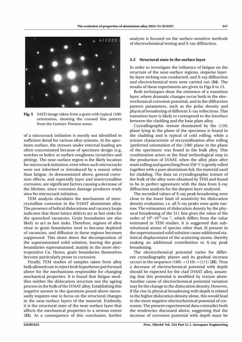
4. Selected area electron diffraction (SAED) imagesreveal the presence of randomly distributedGuinier–Preston zones (crossed diffuse lines arevisible in the SAED images in Fig. 5).
The observations in this study suggest that low-stress, high-cycle fatigue during operating time causesno dramatical structure changes in the bulk mate-rial. Neither phase composition and microchemicalinhomogeniety, on the one hand, nor lattice defectdensity and dislocation structure, on the other, evolveto a significant degree. This phenomenon is widely dis-cussed in the literature [32] for high-cycle fatigue. Itis generally accepted that fatigue failure is the resultof microcrack growth. However, the precise nature
Proc. IMechE Vol. 224 Part G: J. Aerospace Engineering JAERO423
The evolution of properties of aluminium alloy 2024-T4 (D16AT) 347
Fig. 5 SAED image taken from a grain with typical (100)orientation, showing the crossed line patternfrom the Guinier–Preston zones
of a microcrack initiation is mostly not identified insufficient detail for various alloy systems. At the spec-imen surface, the stresses under external loading areoften concentrated because of specimen design (e.g.notches or holes) or surface roughness (scratches andpitting). The near-surface region is the likely locationfor microcrack initiation, even when such microcrackswere not inherited or introduced by a reason otherthan fatigue. As demonstrated above, general corro-sion effects, and especially layer and intercrystallinecorrosion, are significant factors causing a decrease ofthe lifetime, since corrosion damage produces readysites for microcrack initiation.
TEM analysis elucidates the mechanism of inter-crystalline corrosion in the D16AT aluminium alloy.The presence of helical dislocations and vacancy loopsindicates that these lattice defects act as fast sinks forthe quenched vacancies. Grain boundaries are alsolikely to act as fast sinks. Therefore, regions of alloyclose to grain boundaries tend to become depletedof vacancies, and diffusion in these regions becomessuppressed. This slows down the decomposition ofthe supersaturated solid solution, leaving the grainboundaries supersaturated, mainly in the more elec-tropositive Cu. Hence, grain boundaries themselvesbecome particularly prone to corrosion.
Finally, TEM studies of samples taken from alloybulk allowed one to reject both hypotheses put forwardabove for the mechanisms responsible for changingmechanical properties. It is found that fatigue mod-ifies neither the dislocation structure nor the ageingprocess in the bulk of the D16AT alloy. Establishing thisnegative answer to the questions posed above neces-sarily requires one to focus on the structural changesin the near-surface layers of the material. Evidently,it is the structural state of the near-surface layer thataffects the mechanical properties to a serious extent[33]. As a consequence of this conclusion, further
analysis is focused on the surface-sensitive methodsof electrochemical testing and X-ray diffraction.
3.3 Structural state in the surface layer
In order to investigate the influence of fatigue on thestructure of the near-surface regions, stepwise layer-by-layer etching was conducted, and X-ray diffractionand electrochemical tests were carried out [34]. Theresults of these experiments are given in Figs 8 to 13.
Both techniques show the existence of a transitionlayer, where dramatic changes occur both in the elec-trochemical corrosion potential, and in the diffractionpattern parameters, such as the polar density andphysical broadening of different X-ray reflections. Thistransition layer is likely to correspond to the interfacebetween the cladding and the base plate alloy.
Crystallographic texture dominated by the (110)plane lying in the plane of the specimen is found inthe cladding and is typical of cold rolling, while atexture characteristic of recrystallization after rolling(preferred orientation of the (100) plane in the planeof the specimen) was found in the bulk alloy. Thiscombination arises at the final technological step inthe production of D16AT, when the alloy plate aftermain rolling and quenching from 550 ◦C is gently rolledtogether with a pure aluminium foil, the material usedfor cladding. The data on crystallographic texture ofthe bulk of the alloy were obtained by TEM and foundto be in perfect agreement with the data from X-raydiffraction analysis for the deepest layer analysed.
The recorded values of X-ray peak broadening wereclose to the lower limit of sensitivity for dislocationdensity evaluation, i.e. all X-ray peaks were quite nar-row. The estimation of dislocation density by the phy-sical broadening of the 311 line gives the value of theorder of 109–1010 cm−2, which differs from the valueestimated in TEM studies. It is suggested that sub-stitutional atoms of species other than Al present inthe supersaturated solid solution cause additional sta-tistical displacement of the scattering atoms, therebymaking an additional contribution to X-ray peakbroadening.
The electrochemical potential varies for differ-ent crystallography planes and its gradual increaseoccurs in the sequence (100)→(110)→(111) [35]. Thusa decrease of electrochemical potential with depthshould be expected for the clad D16AT alloy, assum-ing that this potential is modified by texture alone.Another cause of electrochemical potential variationmay be the change in the dislocation density. However,if the rise in physical broadening with depth is relatedto the higher dislocation density alone, this would leadto the more negative electrochemical potential of cor-rosion. The present experimental data contradict boththe tendencies discussed above, suggesting that theincrease of corrosion potential with depth must be
JAERO423 Proc. IMechE Vol. 224 Part G: J. Aerospace Engineering

348 S R Salimon, A I Salimon, and A M Korsunsky
related to the change in chemical composition, i.e. thehigher content of the more electropositive elements inthe alloy.
The dependencies of the polar density and X-raypeak breadth on operating time are ambiguous. Pro-vided that the change of polar density does not reflectthe sample-to-sample variation, one may concludethat the polar density of the (110) planes graduallydecreases with operating time in both the near-surfaceand deep layers of the material, while the polar densityof the (100) planes seems to increase with the fre-quency of flights. Peak broadening tends to increasewith operating time in the case of deep layers and withthe frequency of flights in the case of surface layers.
Electrochemical tests characterize much thinnerlayers of material than conventional laboratory X-raydiffraction analysis. By the choice of X-ray radiationsource from the range between Co-Kα and Mo-Kα,the penetration depth into Al can be changed fromabout 50 to 750 μm. In comparison, during potentio-dynamic scanning, only 0.05–0.1 μm is dissolved atthe maximum current density used (1 μA/cm2). Thuselectrochemical tests may be preferred for the inves-tigation of fine effects in the transition layer. The dataof electrochemical tests can be compared with thosefrom SIMS.
It has been found that, while the evolution of X-raycharacteristics with depth is rather smooth, the depen-dence of corrosion potential on depth shows somepeculiarities. After the rise of potential in the transi-tion layer, some characteristic minimum of potentialis observed at a certain depth for the alloys after 11
and 20 years of exploitation. It is suggested that thesame dependence is likely to be valid for the alloyafter 15 years of exploitation. However, only part ofthe complete curve was obtained in the present exper-iments. Moreover, there exists a dependence of thecharacter of the anodic polarization curve on depth.In Fig. 6 anodic polarization curves are shown for dif-ferent depths. Only weak general anodic dissolutionis detected with no distinct peaks in the surface layer,while at a certain depth intensive anodic dissolutionwith several distinct peaks is present. The last effecttends to be weaker in the deeper layers of material.
Microchemical analysis reveals some importanttrends affecting the corrosion behaviour of the D16ATalloy. First, SEM investigation of alloy surface afterpotentiodynamic scanning where distinct peaks wereobserved reveals no difference in the content of allcomponents expect Fe. For Fe, however, the contentin the test region is 50 per cent lower in comparisonwith the untested zone. This fact probably indicatedselective dissolution of the Al–Fe intermetallic parti-cles during testing. Accelerated pitting in the vicinityof Fe-rich phases in Al-based alloys was also reportedin reference [36].
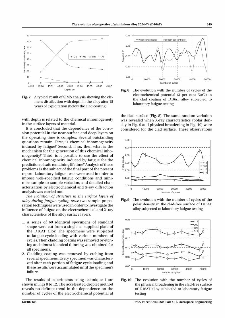
Second, in SIMS experiments the current of Cu andMn secondary ions tends to be two to three timeshigher in the surface layer than in deep layers (seeFig. 7), while the current of Al and Mg secondary ionstends to be lower in the surface layer than in the deeplayers. This chemical inhomogeneity is likely to be thereason for higher corrosion resistance of the surfacelayers. It is also believed that the variation of potential
-0.400(a) (b) (c)
-0.200
0.000
0.200
0.400
0.600
0.800
1.000
0.000 0.200 0.400 0.600 0.800 1.000 1.200i, mA/cm^2
Pot
entia
l, V
0.032 mm
0.059 mm
0.060 mm
0.148 mm
0.300
0.200
-0.100
0.1900.260
0.450
-0.400
-0.200
0.000
0.200
0.400
0.600
0.800
1.000
-0.3 0.2 0.7 1.2
i, mA
Pot
entia
l, V
0.037
0.0820.124
0.139
-0.400
-0.200
0.000
0.200
0.400
0.600
0.800
1.000
0.000 0.500 1.000 1.500
i, mA/cm^2
Pot
entia
l, V
0.033 mm0.037 mm0.055 mm0.057 mm0.158 mm
Fig. 6 The evolution of the anodic polarization curve shape for different depths in the alloy (shownin the legend) after: (a) 11 years of exploitation, (b) 15 years of exploitation, and (c) 20 yearsof exploitation
Proc. IMechE Vol. 224 Part G: J. Aerospace Engineering JAERO423
The evolution of properties of aluminium alloy 2024-T4 (D16AT) 349
0
10
20
30
40
50
60
70
80
44.99 45.00 45.01 45.02 45.03 45.04 45.05 45.06 45.07
Depth, µm
Sec
onda
ry io
n cu
rren
t, a.
u.
Cu Mg Mn Al
Fig. 7 A typical result of SIMS analysis showing the ele-ment distribution with depth in the alloy after 15years of exploitation (below the clad coating)
with depth is related to the chemical inhomogeneityin the surface layers of material.
It is concluded that the dependence of the corro-sion potential in the near-surface and deep layers onthe operating time is complex. Several outstandingquestions remain. First, is chemical inhomogeneityinduced by fatigue? Second, if so, then what is themechanism for the generation of this chemical inho-mogeneity? Third, is it possible to use the effect ofchemical inhomogeneity induced by fatigue for theprediction of safe remaining lifetime? Analysis of theseproblems is the subject of the final part of the presentreport. Laboratory fatigue tests were used in order toimpose well-specified fatigue conditions and mini-mize sample-to-sample variation, and detailed char-acterization by electrochemical and X-ray diffractionanalysis was carried out.
The evolution of structure in the surface layers ofalloy during fatigue cycling tests: two sample prepa-ration techniques were used in order to investigate theinfluence of fatigue on the electrochemical and X-raycharacteristics of the alloy surface layers.
1. A series of 60 identical specimens of standardshape were cut from a single as-supplied plate ofthe D16AT alloy. The specimens were subjectedto fatigue cycle loading with various numbers ofcycles. Then cladding coating was removed by etch-ing and almost identical thinning was obtained forall specimens.
2. Cladding coating was removed by etching fromseveral specimens. Every specimen was characteri-zed after each portion of fatigue cycle loading andthese results were accumulated until the specimen’sfailure.
The results of experiments using technique 1 areshown in Figs 8 to 12. The accelerated droplet methodreveals no definite trend in the dependence on thenumber of cycles of the electrochemical potential at
-0.75
-0.70
-0.65
-0.60
-0.550 10000 20000 30000 40000 50000
Number of cycles
Pot
entia
l, V
Near concentrator Far from concentrator
Fig. 8 The evolution with the number of cycles of theelectrochemical potential (3 per cent NaCl) inthe clad coating of D16AT alloy subjected tolaboratory fatigue testing
the clad surface (Fig. 8). The same random variationwas revealed when X-ray characteristics (polar den-sity in Fig. 9 and physical broadening in Fig. 10) wereconsidered for the clad surface. These observations
0.00
1.00
2.00
3.00
4.00
5.00
6.00
0 10000 20000 30000 40000 50000Number of cycles
Pol
ar d
ensi
ty
111100110311
Fig. 9 The evolution with the number of cycles of thepolar density in the clad-free surface of D16ATalloy subjected to laboratory fatigue testing
0.00
0.05
0.10
0.15
0.20
0.25
0 10000 20000 30000 40000 50000Number of cycles
Phy
sica
l bro
aden
ing,
deg
111200220311
Fig. 10 The evolution with the number of cycles ofthe physical broadening in the clad-free surfaceof D16AT alloy subjected to laboratory fatiguetesting
JAERO423 Proc. IMechE Vol. 224 Part G: J. Aerospace Engineering

350 S R Salimon, A I Salimon, and A M Korsunsky
0.2
0.22
0.24
0.26
0.28
0.3
0.32
0 5000 10000 20000 25000 30000 40000 50000Number of cycles
Pot
entia
l, -V
Fig. 11 The evolution with the number of cycles of thecorrosion potential (12 per cent H2SO4) in theclad-free surface of D16AT alloy subjected tolaboratory fatigue testing
correspond to the conventional paradigm of high-cycle fatigue, where no clearly discernible structuralchanges are thought to occur in the sample.
However, different trends were observed at the clad-free alloy surface. The corrosion potential reaches amaximum after 10 000 cycles and eventually approa-ches a steady-state level after 30 000 cycles. A gen-eral increase of potential with the number of cycles
-0.4
-0.2
0
0.2
0.4
0.6
0.8
1
0.000 0.500 1.000 1.500 2.000 2.500
i, mA/cm^2
Pot
entia
l, V
0 cycles5 00010 00020 00025 00030 00040 00050 000
Fig. 12 The evolution with the number of cycles of thepotentiodynamic anodic polarization curves inthe clad-free surface of D16AT alloy subjected tolaboratory fatigue testing
is detected, which is ascribed here to the increasingchemical inhomogeneity induced by fatigue. This maybe due to layers of alloy lying at certain depths tend-ing to become enriched in the more noble elements.It is also apparent from Fig. 12 that fatigue affects theform of the anodic dissolution curve obtained duringpotentiodynamic scanning.
Other trends are found for the surface layers ofsamples prepared using technique 2. First, the cor-rosion potential generally tends to decrease with thenumber of cycles both in the vicinity and far fromthe round concentrator hole machined in the speci-mens. However, a transient maximum of potentialcould be detected at an early stage of cycling (Fig. 13).Second, physical broadening increases rapidly in theearliest period of specimen’s cyclic life, and remainslargely constant for the remaining lifetime (Fig. 14).The increase in the physical broadening is more pro-nounced near the concentrator. In the narrow zonenear a growing crack the value of physical broaden-ing may differ from that in the larger zone aroundthe concentrator. This phenomenon is ascribed hereto a complex character of structural evolution near the
0.00
0.05
0.10
0.15
0.20
0.25
0.30
0.35
0 20 40 60 80 100Life time, %
Pot
entia
l, -V
near concentrator far from concentrator
(a)
0.00
0.05
0.10
0.15
0.20
0.25
0.30
0.35
0.40
0 20 40 60 80 100Life time, %
Pot
entia
l, -V
near concentrator far from concentrator
(b)
Fig. 13 The evolution of corrosion potential (10 per centH2SO4, the ‘drip’ method) during the life of asingle specimen subjected to a fatigue test. Mea-surements were taken in the vicinity of and awayfrom: (a) a small round concentrator and (b) alarge round concentrator
Proc. IMechE Vol. 224 Part G: J. Aerospace Engineering JAERO423
The evolution of properties of aluminium alloy 2024-T4 (D16AT) 351
0.00
0.05
0.10
0.15
0.20
0.25
0.30
0.35
0 20 40 60 80 100
Life time, %
Phy
sica
l bro
aden
ing,
deg
200111220311
(a)
0.00
0.05
0.10
0.15
0.20
0.25
0 20 40 60 80 100
Life time, %
Phy
sica
l bro
aden
ing,
deg
200111220311
(b)
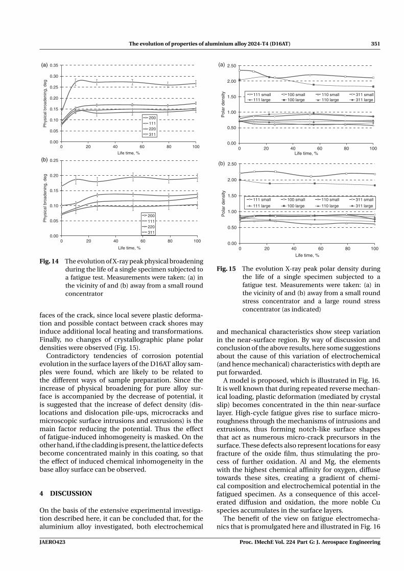
Fig. 14 The evolution of X-ray peak physical broadeningduring the life of a single specimen subjected toa fatigue test. Measurements were taken: (a) inthe vicinity of and (b) away from a small roundconcentrator
faces of the crack, since local severe plastic deforma-tion and possible contact between crack shores mayinduce additional local heating and transformations.Finally, no changes of crystallographic plane polardensities were observed (Fig. 15).
Contradictory tendencies of corrosion potentialevolution in the surface layers of the D16AT alloy sam-ples were found, which are likely to be related tothe different ways of sample preparation. Since theincrease of physical broadening for pure alloy sur-face is accompanied by the decrease of potential, itis suggested that the increase of defect density (dis-locations and dislocation pile-ups, microcracks andmicroscopic surface intrusions and extrusions) is themain factor reducing the potential. Thus the effectof fatigue-induced inhomogeneity is masked. On theother hand, if the cladding is present, the lattice defectsbecome concentrated mainly in this coating, so thatthe effect of induced chemical inhomogeneity in thebase alloy surface can be observed.
4 DISCUSSION
On the basis of the extensive experimental investiga-tion described here, it can be concluded that, for thealuminium alloy investigated, both electrochemical
0.00
0.50
1.00
1.50
2.00
2.50
0 20 40 60 80 100Life time, %
Pol
ar d
ensi
ty 111 small 100 small 110 small 311 small111 large 100 large 110 large 311 large
(a)
0.00
0.50
1.00
1.50
2.00
2.50
0 20 40 60 80 100
Life time, %
Pol
ar d
ensi
ty
111 small 100 small 110 small 311 small
111 large 100 large 110 large 311 large
(b)
Fig. 15 The evolution X-ray peak polar density duringthe life of a single specimen subjected to afatigue test. Measurements were taken: (a) inthe vicinity of and (b) away from a small roundstress concentrator and a large round stressconcentrator (as indicated)
and mechanical characteristics show steep variationin the near-surface region. By way of discussion andconclusion of the above results, here some suggestionsabout the cause of this variation of electrochemical(and hence mechanical) characteristics with depth areput forwarded.
A model is proposed, which is illustrated in Fig. 16.It is well known that during repeated reverse mechan-ical loading, plastic deformation (mediated by crystalslip) becomes concentrated in the thin near-surfacelayer. High-cycle fatigue gives rise to surface micro-roughness through the mechanisms of intrusions andextrusions, thus forming notch-like surface shapesthat act as numerous micro-crack precursors in thesurface. These defects also represent locations for easyfracture of the oxide film, thus stimulating the pro-cess of further oxidation. Al and Mg, the elementswith the highest chemical affinity for oxygen, diffusetowards these sites, creating a gradient of chemi-cal composition and electrochemical potential in thefatigued specimen. As a consequence of this accel-erated diffusion and oxidation, the more noble Cuspecies accumulates in the surface layers.
The benefit of the view on fatigue electromecha-nics that is promulgated here and illustrated in Fig. 16
JAERO423 Proc. IMechE Vol. 224 Part G: J. Aerospace Engineering

352 S R Salimon, A I Salimon, and A M Korsunsky
Fig. 16 An illustration for the mechanism of fatigue-induced chemical inhomogeneity: (a) initialstructure of the clad alloy and (b) evolution ofelement concentration induced by fatigue
is that it highlights the clear link existing betweenmechanical deformation effects (slip, plasticity, andsurface roughening) and chemical processes (surfaceoxide layer formation and break-up, and diffusion ofalloying elements through the near-surface layers ofthe material). It is the authors’ belief that this rep-resents an improvement in the knowledge about thechemo-mechanics of fatigue in aluminium alloys.
5 CONCLUSIONS
In the present study, a variety of experimental tech-niques were employed to consider the complex inter-actions between fatigue and corrosion processes. Theparticular novelty of the present approach lies inthe attempt to establish a connection between elec-trochemical and micro-mechanical properties of alu-minium alloy samples and engineering components.A further substantial difference between the presentstudy and others found in the literature is that realcomponents that had experienced many years of ser-vice exposure were studied alongside laboratory testspecimens.
Some experimental facts reported in the presentstudy give evidence that changes in the structure andchemical composition during high-cycle fatigue of thealuminium alloy D16AT are confined to a very thinsurface layer. It has been demonstrated that electro-chemical tests are more sensitive to these changesthan X-ray diffractometry.
Figure 11 illustrates the evolution with the numberof cycles of the corrosion potential (12 per cent H2SO4)in the clad-free surface of D16AT alloy subjected tolaboratory fatigue testing. A connection is observedbetween the corrosion potential and the number ofcycles experienced by the material. After about 10 000cycles the corrosion potential exhibits a reduction ofabout 30 per cent with respect to the initial value, fol-lowed by the gradual increase to a steady-state valuethat is about 20 per cent lower than the initial value.Note that structural changes in the aluminium alloydue to high-cycle fatigue loading are otherwise verydifficult to detect.
Although certain difficulties were encountered bothin the sample preparation and in the interpretation ofexperimental data, the data collected suggest that, inthe longer term, further development of the electro-chemical technique for fatigue diagnostics is likely toyield a useful and powerful means for safe residuallifetime evaluation. Finally, another novel develop-ment appearing in the present article is the newlyproposed micro-mechanical model of the corrosionprocess, illustrated in Fig. 16.
Some mechano-chemical connection of the typesought has been established, although the resultsremain incomplete, and further investigations areclearly required.
© Authors 2010
REFERENCES
1 Suresh, S. Fatigue of materials, 1991 (Cambridge Univer-sity Press, Cambridge).
2 Vasiliev, V. Y. and Shapkin, V. S. Structural corrosionand electrochemical diagnostics of alloys, 1998 (RussianProcess Engineering Publishers, Moscow).
3 Rao, K. S. and Rao, K. P. Pitting corrosion of heat-treatable aluminium alloys and welds: a review. Trans.Indian Inst. Met., 2004, 57, 593–610.
4 Uhlig, H. H. Adsorbed and reaction-product films onmetals. J. Electrochem. Soc., 1950, 97, 215.
5 Sato, N. Theory for breakdown of anodic oxide films onmetals. Electrochim. Acta, 1971, 16, 1683.
6 Urquidi, M. and MacDonald, D. D. J. Electrochem. Soc.,1985, 132, 555.
7 Williams, D. E., Westcott, C., and Fleischmann, M.Stochastic models of pitting corrosion of stainless steels.J. Electrochem. Soc., 1985, 132, 1804.
8 Foley, R. T. Localized corrosion of aluminum alloys – areview. Corrosion, 1986, 42, 277.
Proc. IMechE Vol. 224 Part G: J. Aerospace Engineering JAERO423

The evolution of properties of aluminium alloy 2024-T4 (D16AT) 353
9 Szklarska-Smialowska, Z. Pitting corrosion of alumin-ium. Corros. Sci., 1999, 41, 1743–1767.
10 Frankel, G. S., Stockert, L., Hunkeler, F., and Bohni, H.Metastable pitting of stainless-steel. Corrosion, 1987, 43,429–436.
11 Szklarska-Smialowska, Z. Pitting corrosion of metals,1986, p. 347 (National Association of Corrosion Engineers(NACE), Houston, Texas).
12 Godard, H. P. The corrosion behavior of aluminum innatural waters. Can. J. Chem. Eng., 1960, 21(167), 104.
13 Hunkeler, F. and Boehni, H. Determination of pit growthrates on aluminum using a metal foil technique. Corro-sion, 1981, 37, 645.
14 Dix, J. R., Brown, R. H., and Binger, W. H. The resistanceof aluminum alloys to corrosion. In Metals handbook 1,1975, p. 916 (American Society for Metals, Metals Park,Ohio, USA).
15 Hollingsworth, E. H. and Hunsicker, H. Metals hand-book, vol. 13, 1987, p. 583 (ASM International, MetalsPark, Ohio, USA).
16 Buchheit, R. G. A compilation of corrosion potentialsreported for intermetallic phases in aluminum-alloys.J. Electrochem. Soc., 1995, 142, 3994–3996.
17 Mazurkiewicz, B. and Piotrowski, A. The electrochem-ical behaviour of the Al2Cu intermetallic compound.Corros. Sci., 1983, 23, 697.
18 Mazurkiewicz, B. Electrochemical behavior of theAl8Mg5 intermetallic compound. Corros. Sci., 1983, 23,687.
19 Scully, J. R., Knight, T. O., Buchheit, R. G., and Peebles,D. E. Electrochemical characteristics of the Al2Cu, Al3Taand Al3Zr intermetallic phases and their relevancy to thelocalized corrosion of Al alloys. Corros. Sci., 1993, 35, 185.
20 Buchheit, R. G., Grant, R. P., Hlava, P. F., McKenzie, B.,and Zender, G. L. Local dissolution phenomena associ-ated with S phase (Al2CuMg) particles in aluminum alloy2024-T3. J. Electrochem. Soc., 1997, 144, 2621.
21 Buchheit, R. G., Moran, J. P., and Stoner, G. E. Local-ized corrosion behavior of alloy 2090 – the role ofmicrostructural heterogeneity. Corrosion, 1990, 46, 610.
22 Wang, M. F., Li, X. G., Dub, N., Huang, Y. Z., and Kor-sunsky, A. Direct evidence of initial pitting corrosion.Electrochem. Commun., 2008, 10, 1000–1004.
23 Chlistovsky, R. M., Heffernan, P. J., and DuQuesnay, D. L.Corrosion-fatigue behaviour of 7075-T651 aluminumalloy subjected to periodic overloads. Int. J. Fatigue, 2007,29, 1941–1949.
24 Ciccone, M. P., Gangloff, R. P., and Kelly, R. G. Testenvironment selection for corrosion-fatigue testing ofaluminum alloy 7075-T6. Corrosion, 2005, 61, 571–578.
25 Liu, Y., Arenas, M. A., Skeldon, P., Thompson, G. E.,Bailey, P., Noakes, T. C. Q., Habazaki, H., andShimizu, K. Anodic behaviour of a model second phase:Al-20at.%Mg-20at.%Cu. Corros. Sci., 2006, 48, 1225–1248.
26 de Miera, M. S., Curioni, M., Skeldon, P., and Thompson,P. G. E. Investigation of the corrosion behaviour of AA2024-T3 in low concentrated chloride media. Corros. Sci.,2008, 50, 2646–2657.
27 Pidaparti, R. M. Structural corrosion health assess-ment using computational intelligence methods. Struct.Health Monit., 2007, 6, 245–259.
28 Shelekhov, E. V. and Sviridova, T. A. Programs for x-rayanalysis of polycrystals. Metal Sci. Heat Treat., 2000, 42,309–313.
29 Cabot, P. L., Perez, E., and Virgili, J. Oxide dissolutionduring galvanostatic oxidation of aluminum. Anal. deQuim. Ser. A-Quim. Fis. Y Quim. Tec., 1985, 81, 434–436.
30 Smith, R. A. Fine-tuning the eddy current detectionof hidden first-layer corrosion in aircraft skins. Insight,1998, 40, 712–721.
31 Freyman, L. I. Kinetics of metal pitting corrosion. In Cor-rosion and protection, 1985, pp. 3–71 (VINITI, Moscow).
32 Sinyavsky,V. S.,Val’kov,V. D., and Budov, G. M. Corrosionand protection of aluminium alloys, 1979 (Metallurgiya,Moscow).
33 Kelly, A. and Nicholson, R. B. Strengthening methods incrystals, 1971 (Elsevier, London).
34 Pourbaix, M. Lectures on electrochemical corrosion, 1973(Plenum Press, New York).
35 Garz, J. and Schatt, W. Zeitschrift für physikalische.Chemie, 1969, B240, 371–379.
36 Vasiliev,V. Y., Kukolkin, A. G., Bayankin,V. Y., Gromov, M.S., and Volkov, V. A. The variation of corrosion suscepti-bility of aluminium alloys during exploitation. Met. Prot.,1995, 31, 16–20.
JAERO423 Proc. IMechE Vol. 224 Part G: J. Aerospace Engineering
Related Documents