Heat Transfer Measurements for a Film Cooled Turbine Vane Cascade by Douglas R. Thurman, Philip E. Poinsatte, and James D. Heidmann ARL-MR-0697 May 2008 Approved for public release; distribution unlimited.

Welcome message from author
This document is posted to help you gain knowledge. Please leave a comment to let me know what you think about it! Share it to your friends and learn new things together.
Transcript
Heat Transfer Measurements for a Film Cooled Turbine
Vane Cascade
by Douglas R. Thurman, Philip E. Poinsatte, and James D. Heidmann
ARL-MR-0697 May 2008 Approved for public release; distribution unlimited.

NOTICES
Disclaimers The findings in this report are not to be construed as an official Department of the Army position unless so designated by other authorized documents. Citation of manufacturer’s or trade names does not constitute an official endorsement or approval of the use thereof. Destroy this report when it is no longer needed. Do not return it to the originator.
Army Research Laboratory Adelphi, MD 20783-1197
ARL-MR-0697 May 2008
Heat Transfer Measurements for a Film Cooled Turbine Vane Cascade
Douglas R. Thurman
Vehicle Technology Directorate, ARL
Philip E. Poinsatte and James D. Heidmann National Aeronautics and Space Administration
Approved for public release; distribution unlimited.

ii
REPORT DOCUMENTATION PAGE Form Approved OMB No. 0704-0188
Public reporting burden for this collection of information is estimated to average 1 hour per response, including the time for reviewing instructions, searching existing data sources, gathering and maintaining the data needed, and completing and reviewing the collection information. Send comments regarding this burden estimate or any other aspect of this collection of information, including suggestions for reducing the burden, to Department of Defense, Washington Headquarters Services, Directorate for Information Operations and Reports (0704-0188), 1215 Jefferson Davis Highway, Suite 1204, Arlington, VA 22202-4302. Respondents should be aware that notwithstanding any other provision of law, no person shall be subject to any penalty for failing to comply with a collection of information if it does not display a currently valid OMB control number. PLEASE DO NOT RETURN YOUR FORM TO THE ABOVE ADDRESS. 1. REPORT DATE (DD-MM-YYYY)
May 2008 2. REPORT TYPE
3. DATES COVERED (From - To)
5a. CONTRACT NUMBER
5b. GRANT NUMBER
4. TITLE AND SUBTITLE
Heat Transfer Measurements for a Film Cooled Turbine Vane Cascade
5c. PROGRAM ELEMENT NUMBER
5d. PROJECT NUMBER
5e. TASK NUMBER
6. AUTHOR(S)
Douglas R. Thurman, Philip E. Poinsatte, and James D. Heidmann
5f. WORK UNIT NUMBER
7. PERFORMING ORGANIZATION NAME(S) AND ADDRESS(ES)
NASA John H. Glenn Research Center ATTN: AMSRD-ARL-VT-EC 21000 Brookpark Road Cleveland, OH 44135
8. PERFORMING ORGANIZATION REPORT NUMBER
ARL-MR-0697
10. SPONSOR/MONITOR'S ACRONYM(S)
9. SPONSORING/MONITORING AGENCY NAME(S) AND ADDRESS(ES)
11. SPONSOR/MONITOR'S REPORT NUMBER(S)
12. DISTRIBUTION/AVAILABILITY STATEMENT
Approved for public release; distribution unlimited.
13. SUPPLEMENTARY NOTES
14. ABSTRACT
Experimental heat transfer and pressure measurements were obtained on a large scale film cooled turbine vane cascade. The objective was to investigate heat transfer on a commercial high pressure first stage turbine vane at near engine Mach and Reynolds number conditions. Additionally blowing ratios and coolant density were also matched. Numerical computations were made with the Glenn-HT code of the same geometry and compared with the experimental results. We used a transient thermochromic liquid crystal technique to obtain steady state heat transfer data on the mid-span geometry of an instrumented vane with 12 rows of circular and shaped film cooling holes. A mixture of SF6 and Argon gases was used for film coolant to match the coolant-to-gas density ratio of a real engine. The exit Mach number and Reynolds number were 0.725 and 2.7 million respectively. Trends from the experimental heat transfer data matched well with the computational prediction, particularly for the film cooled case. 15. SUBJECT TERMS
Heat transfer, liquid crystal, film cooling, turbine vane
16. SECURITY CLASSIFICATION OF: 19a. NAME OF RESPONSIBLE PERSON
Douglas R. Thurman a. REPORT
U b. ABSTRACT
U c. THIS PAGE
U
17. LIMITATION OF ABSTRACT
SAR
18. NUMBER OF PAGES
26 19b. TELEPHONE NUMBER (Include area code)
216-433-6573 Standard Form 298 (Rev. 8/98) Prescribed by ANSI Std. Z39.18
iii
Contents
List of Figures iv
List of Tables iv
Introduction 1
Nomenclature 2
Subscripts 3
Apparatus 3
Procedure 7
Glenn-HT Computations 9
Results and Discussion 12
Conclusion 16
References 17
Distribution List 19

iv
List of Figures
Figure 1. Test facility......................................................................................................................3 Figure 2. Film cooled vane cascade................................................................................................4 Figure 3. Film cooled vane. ............................................................................................................5 Figure 4. Vane Cross section and film hole numbers. ....................................................................5 Figure 5. Film hole angles. .............................................................................................................6 Figure 6. Leading edge region of computational grid...................................................................11 Figure 7. Stagnation temperature contours on plane of fixed span...............................................12 Figure 8. Mid-span flow pressure survey. ....................................................................................13 Figure 9. Vane loading comparison. .............................................................................................13 Figure 10. Stanton number for no film cooling case, Re = 2.7E6, Mach = 0.725. .......................14 Figure 11. Stanton number for film cooled case, Re = 2.7E6, Mach = 0.725, density ratio =
1.92...........................................................................................................................................15
List of Tables
Table 1. Film cooling hole parameters. ..........................................................................................6 Table 2. Test conditions..................................................................................................................8
1
Introduction
With turbine engine temperatures exceeding material properties, one way to protect the engine components exposed to the hot freestream gas is to use film cooling to provide a layer of cooler air over the material surface. This is especially useful for first stage high pressure turbine vanes which experience the hottest temperatures in the engine. Various studies have looked at the characteristics and effectiveness of film cooling. Early research by Goldstein (1971) involved a flat plate to simulate the environment of a film cooled turbine blade. Saumweber (2004) and Gritsch, et al., (1998) have used flat plates and heated air to match coolant-to-air density ratios of real engines. When reproducing the temperature extremes seen in a real engine is not possible, foreign gas can be used for the coolant in experiments in order to match the coolant-to-air density ratios of real engines. Ekkad, et al., (1997) have used flat plates and foreign gases to match the density ratio. Film cooling studies with more realistic geometries have also been investigated. Colban, et al., (2006), Cutbirth and Bogard (2002), Ethridge, et al., (2001), and Ames (1996) have used scaled blade geometries to study various aspects of film cooling. These experimental studies, however, often do not match typical real engine flow conditions, such as Mach number and Reynolds number.
There have been several computational studies that have focused on film cooling with realistic blade geometries and plenum effects. Garg and Rigby (1998) modeled a film cooled blade with angled showerhead holes as well as with plenums. Bohn, et al., (1997) also modeled a film cooled blade with normal holes. Heidmann, et al., (2000) modeled a realistic Honeywell vane geometry with film cooling and near-real engine flow conditions. This geometry consisted of showerhead compound-angled holes and pressure and suction side holes with shaped holes on the pressure side.
Little experimental data has been published at realistic engine flow conditions. Abuaf, et al., (1998) studied roughness effects on heat transfer of an uncooled turbine vane at several flow conditions typical of real engines. Haldeman et al., (2006) published unsteady aerodynamic and heat transfer results for a Honeywell film cooled rotating turbine stage in a blow-down facility. This was the first attempt to measure film cooled turbine heat transfer in such a realistic environment with research-quality instrumentation. The present geometry nominally represents the extruded vane mid-span profile and film cooling pattern from the Haldeman et al., (2006) study, and matches the geometry investigated by Heidmann, et al., (2000).
The present study provides experimental data at near-real engine flow conditions for the Honeywell vane, and offers the opportunity to generate high-resolution vane heat transfer data in a steady-flow cascade environment. The data will also help validate the computational heat transfer analysis performed by NASA’s Glenn-HT code on this vane geometry. We used a transient liquid crystal technique to obtain the heat transfer data. Mach number and Reynolds

2
number nearly match real engine conditions at the exit of a first stage turbine vane. Coolant-to-gas density ratio is also matched using a combination of Argon and SF6 gases for film coolant. The matching of these key flow parameters for a film cooled turbine with detailed local temperature measurement is a key element of this study. In the current test, the vane model is scaled large enough to yield adequate special resolution of the surface heat transfer. This NASA wind tunnel facility has enough flow throughput to nearly match real engine conditions of not only Reynolds number, but also exit Mach number at generally atmospheric tunnel conditions.
Nomenclature
c vane true chord
cp specific heat of test vane material
d film hole diameter
h heat transfer coefficient
k thermal conductivity
p film hole spanwise pitch
Re Reynolds number based on true chord and exit conditions
s streamwise distance from leading edge
St Stanton number
t time
T temperature
V velocity
α streamwise film hole angle
β spanwise film hole angle
βh non-dimensional time
ρ density of test vane material
θ non-dimensional temperature

3
Subscripts
i initial
s surface
t total
Apparatus
We used a four blade, five passage linear cascade for the experimental tests. The facility is shown in figure 1, and the cascade is shown in figure 2. The simulated turbine vanes were based on the mid-span coordinates of a first stage high pressure turbine of a Honeywell engine. Room temperature air was drawn into the tunnel by a vacuum exhaust system. We attached an elliptical one-dimensional aluminum bellmouth to the inlet of the cascade. The walls of the cascade were made of 0.75 in (1.91 cm) thick clear acrylic. The test vanes were made by rapid prototyping technique of a Duraform polyamide sintering material (nylon), and had a chord of 8.09 in (20.5 cm), span of 5 inches (12.7 cm), a 76 degree turning angle, and were scaled 2.9:1 to match the engine exit Mach number and exit Reynolds number. The passage width between the vanes was 6 inches (15.2 cm). We used adjustable tailboards to ensure periodicity of the flow between the passages of the cascade.
Figure 1. Test facility.
4
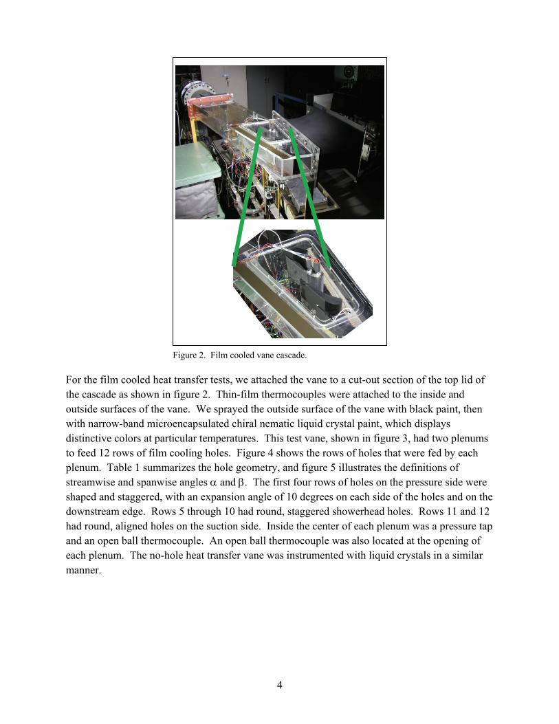
Figure 2. Film cooled vane cascade.
For the film cooled heat transfer tests, we attached the vane to a cut-out section of the top lid of the cascade as shown in figure 2. Thin-film thermocouples were attached to the inside and outside surfaces of the vane. We sprayed the outside surface of the vane with black paint, then with narrow-band microencapsulated chiral nematic liquid crystal paint, which displays distinctive colors at particular temperatures. This test vane, shown in figure 3, had two plenums to feed 12 rows of film cooling holes. Figure 4 shows the rows of holes that were fed by each plenum. Table 1 summarizes the hole geometry, and figure 5 illustrates the definitions of streamwise and spanwise angles α and β. The first four rows of holes on the pressure side were shaped and staggered, with an expansion angle of 10 degrees on each side of the holes and on the downstream edge. Rows 5 through 10 had round, staggered showerhead holes. Rows 11 and 12 had round, aligned holes on the suction side. Inside the center of each plenum was a pressure tap and an open ball thermocouple. An open ball thermocouple was also located at the opening of each plenum. The no-hole heat transfer vane was instrumented with liquid crystals in a similar manner.

5
Figure 3. Film cooled vane.
Figure 4. Vane Cross section and film hole numbers.

6
Table 1. Film cooling hole parameters.
Row s/c No. holes Type p/d α β
1 –0.447 10 shaped, staggered pressure side 4.06 65.5 0
2 –0.385 10 shaped, staggered pressure side 4.06 62.9 0
3 –0.182 10 shaped, staggered pressure side 4.06 63.8 0
4 –0.142 10 shaped, staggered pressure side 4.06 61.4 0
5 –0.053 11 round, staggered showerhead 4.06 6.2 60
6 –0.032 11 round, staggered showerhead 4.06 2.7 60
7 –0.011 11 round, staggered showerhead 4.06 0.9 60
8 0.011 11 round, staggered showerhead 4.06 0.9 60
9 0.033 11 round, staggered showerhead 4.06 2.9 60
10 0.054 11 round, staggered showerhead 4.06 4.4 60
11 0.116 15 round, aligned suction side 2.71 44.5 0
12 0.157 15 round, aligned suction side 2.71 47.0 0
Figure 5. Film hole angles.
We used a heater oven, covered with an automatic temperature-controlled heater blanket, to heat the heat transfer vanes. Low heat emitting lights were used to illuminate the model. We recorded the video data with cameras and digital recorders. A time-date generator was used to superimpose the time onto the video data. A commercial data acquisition system recorded pressure and temperature data.
Since the temperature difference that exists in a real engine could not be reproduced in this facility, we used a combination of Argon and Sulfur Hexafluoride (SF6) for the film cooling gas which provided a coolant-to-freestream density ratio of 1.92. Coolant flow to the instrumented heat transfer vane was supplied by Argon and SF6 tanks. To achieve the correct density ratio,

7
four mass flow controllers were used to control the gas flow rates, with each tank flow being split into two mass flow controllers. We then mixed the gases from one SF6 controller and one Argon controller together prior to entering each vane plenum.
To obtain static surface pressure data, we used a vane with no film cooling holes with static pressure taps located along the mid-span height of the vane. Static pressure taps were also located along the mid-span height of the adjacent vanes, as well as on the lower endwall of the tunnel at discreet locations upstream and downstream of the vanes. Total pressure survey data was taken at mid-height upstream and downstream of the vanes with a 3-hole total pressure probe.
Procedure
The tunnel flow conditions were set prior to the test by a downstream flow control valve. We conducted heat transfer tests using a transient liquid crystal technique similar to that described in Poinsatte and Thurman (2007) to measure heat transfer coefficients. We placed the test vane in the heater oven and heated it to a uniform temperature of nominally 150 °F (65.6 °C). When the model reached the desired temperature, the data acquisition system and video recorders were started. We opened the oven and placed the heated vane in the tunnel. The time to transfer the vane to the tunnel was less than two seconds. The surface temperature decreased less than 1 degree and was included in our uncertainty calculations. Room temperature air was then suddenly drawn through the cascade with a fast-opening valve, which produced a near step change in flow startup. The airflow cooled the previously heated model and the model surface temperature was indicated by the liquid crystal color. We recorded the resulting liquid crystal color patterns showing continuous surface temperatures with time. Knowing this time temperature history allows calculation of heat transfer coefficients, as described below. For the present study, we examined only the mid-span region of the vane. The yellow color band of the liquid crystal was used to calculate the heat transfer coefficients and was calibrated to be 100 °F (37.8 °C). Test conditions are summarized in table 2.
8
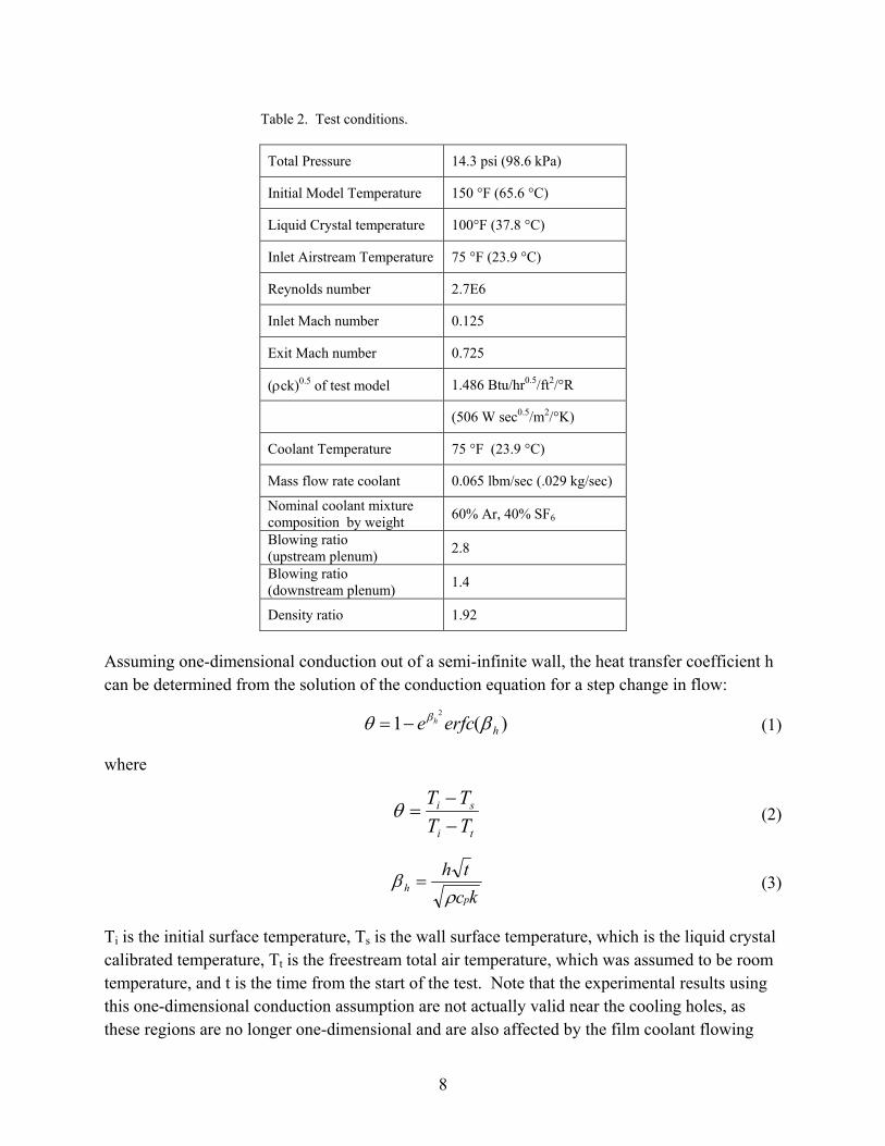
Table 2. Test conditions.
Total Pressure 14.3 psi (98.6 kPa)
Initial Model Temperature 150 °F (65.6 °C)
Liquid Crystal temperature 100°F (37.8 °C)
Inlet Airstream Temperature 75 °F (23.9 °C)
Reynolds number 2.7E6
Inlet Mach number 0.125
Exit Mach number 0.725
(ρck)0.5 of test model 1.486 Btu/hr0.5/ft2/°R
(506 W sec0.5/m2/°K)
Coolant Temperature 75 °F (23.9 °C)
Mass flow rate coolant 0.065 lbm/sec (.029 kg/sec)
Nominal coolant mixture composition by weight 60% Ar, 40% SF6
Blowing ratio (upstream plenum) 2.8
Blowing ratio (downstream plenum) 1.4
Density ratio 1.92
Assuming one-dimensional conduction out of a semi-infinite wall, the heat transfer coefficient h can be determined from the solution of the conduction equation for a step change in flow:
)(12
herfce h βθ β−= (1)
where
ti
si
TTTT
−−
=θ (2)
kc
thp
h ρβ = (3)
Ti is the initial surface temperature, Ts is the wall surface temperature, which is the liquid crystal calibrated temperature, Tt is the freestream total air temperature, which was assumed to be room temperature, and t is the time from the start of the test. Note that the experimental results using this one-dimensional conduction assumption are not actually valid near the cooling holes, as these regions are no longer one-dimensional and are also affected by the film coolant flowing
9
through the holes. This will result in higher experimental uncertainties near the holes. When film coolant was used, the coolant was at the same room temperature as the freestream air temperature. Heat transfer magnitudes and locations were determined by the location of the yellow isotherms produced by the liquid crystals on the surface. We then calculated Stanton number based on inlet conditions using the following definition:
pVc
hStρ
= (4)
We acquired pressure survey measurements under steady state conditions. Total pressure and flow angle measurements were taken upstream and downstream of the vanes at mid-span height to verify that the flow between the passages was periodic. We also took endwall pressure measurements on the lower surface of the cascade.
An uncertainty analysis was performed based on the method of Kline and McClintock (1953). Overall uncertainties in heat transfer ranged from 5% to 8% for the no-hole vane, and from 8% to 15% for the film cooled vane with most points around 10 percent. The relatively high uncertainty for the film cooled cases is due to the relative uncertainty regarding the coolant temperature at startup. For the first couple of seconds the coolant picks up the residual heat from the plenum of the preheated model. The coolant quickly comes down to the room temperature which is the same as the inlet freestream. This startup transient can bias the measured heat transfer data, but the effect is lessened when the time from startup is sufficiently large, which is where most of the data was taken.
Glenn-HT Computations
The following is a brief summary of the computational methods employed in previously reported calculations in Heidmann et al., (2000). The simulations were performed using a multiblock computer code called Glenn-HT, previously known as TRAF3D.MB (Steinthorsson et al., 1993) which is based on a single block code designed by Arnone et al., (1991). This code is a general purpose flow solver designed for simulations of flows in complicated geometries. The code solves the full compressible Reynolds-averaged Navier-Stokes equations using a multi-stage Runge-Kutta-based multigrid method. It uses the finite volume method to discretize the equations. The code uses central differencing together with artificial dissipation to discretize the convective terms. The overall accuracy of the code is second order. The code employs the k-ω turbulence model developed by Wilcox (1994a, 1994b), with subsequent modifications by Menter (1993) as implemented by Chima (1996). Accurate heat transfer predictions are possible with the code because the model integrates to the walls and no wall functions are used. Rather, the computational grid is generated to be sufficiently fine near walls to produce a y+ value of less than 1.0 at the first grid point away from the wall. For heat transfer a constant value of 0.9 for
10
turbulent Prandtl number, Prt, was used. A constant value of Pr = 0.72 was used. Laminar viscosity was a function of temperature through a 0.7 power law (Schlichting, 1979) and cp was taken to be a constant.
A structured multi-block grid approach was adopted to model this complex geometry. The grid was composed of 1.2 x 10⁶ computational cells. A y+ value of less than 1.0 at the first grid point from the wall was employed at all locations. Several calculations were performed for varying wall spacings, and it was found that further reductions produced little change in the solution. The grid consisted of 20 cells across both the inlet and outlet boundaries, 60 cells on the periodic boundary, over 200 cells around the vane, and 44 cells from the vane to the periodic boundary. These values are consistent with good computational practice.
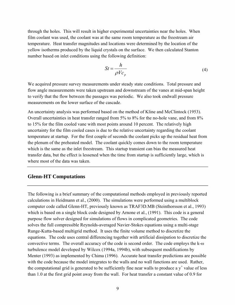
Figure 6 shows the grid in the leading edge region of the vane. All film cooling holes were discretized explicitly, including the fan-shaped holes with expanded exits. In addition, the clustered viscous grids remain attached to all wall boundaries without extending into the flow field. The freestream inlet flow to the vane was at an angle of 0 degrees to the axial direction, with all temperatures and pressures normalized by the inlet stagnation values of 294 K and 101 kPa, respectively. Inlet turbulence intensity of 8.0% and turbulence length scale of 15.0% of vane true chord were applied. The vane downstream exit flow was defined by imposing a constant normalized static pressure which was empirically determined to yield an exit Mach number. Periodicity was enforced in both the blade-to-blade and spanwise directions based on vane and film hole pitches, respectively. We gave all solid walls a no-slip boundary condition in addition to a fixed temperature. The isothermal wall boundary condition extended to all wall surfaces, including the film hole surfaces and plenum surfaces, so heat transfer in the plena and film holes occurred and provided a stagnation temperature profile in the jet exiting each hole. Plenum inflows were modeled as if flowing from the plenum side wall to preserve periodicity in the spanwise direction.
11
Figure 6. Leading edge region of computational grid.
We ran the code for three cases: a solid isothermal blade with no film cooling holes and a wall temperature of 0.7 times the freestream temperature as a baseline, and two film cooled isothermal-wall cases with wall temperatures of 0.7 and 0.8 times the freestream temperature, respectively. These two cases were then used to generate independent distributions of film cooling effectiveness and heat transfer coefficient. The geometry consisted of a spanwise-periodic pitch of the film cooling hole pattern, so no endwall effects were considered. The film cooling holes were fed by two plenums as in the experiment, and the coolant mass flow was set to the engine design overall blowing ratio for each plenum. We set the nominal design density ratio of 2.0 by imposing a film coolant temperature of 0.5 times the freestream inlet temperature. Exit Mach and Reynolds numbers of 0.876 and 2.9 x 10⁶ were employed, respectively.
Figure 7 shows a result of the Glenn-HT simulation, illustrating the stagnation temperature on a fixed-span plane through the centerline of the central suction side film holes. It is immediately evident that the stagnation line intersects this plane between rows 6 and 7 (the second and third showerhead rows from the pressure side) since the high temperature isotherms approach the vane. The freestream impinges at this point, diverting the cooling flow from these rows to opposite sides of the vane. A thinning of the thermal boundary layer is also evident on the pressure side, just upstream of the shaped holes. This will manifest itself as an increase in heat flux at this location. A thermal boundary layer is present inside the plenum and film holes due to the isothermal boundary condition there. The resultant stagnation temperature profile in the film

12
jets is of great interest, as is the velocity profile. Complete results and discussion of the Glenn-HT simulation can be found in Heidmann et al., (2000).
Figure 7. Stagnation temperature contours on plane of fixed span.
Results and Discussion
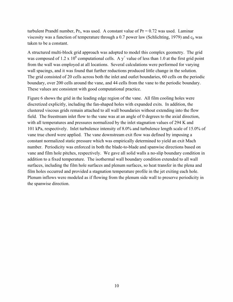
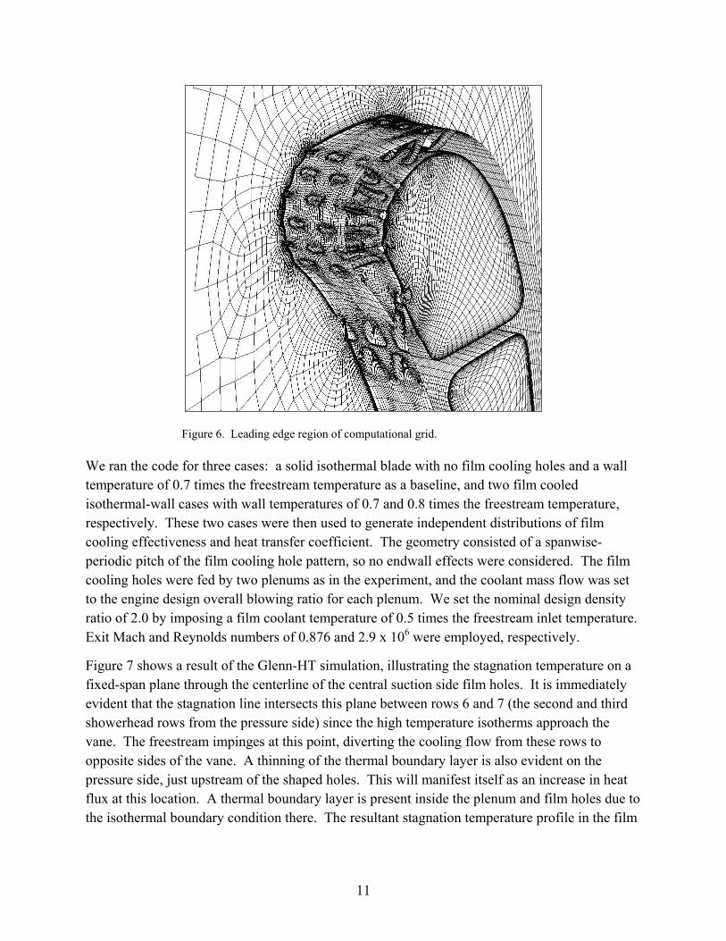
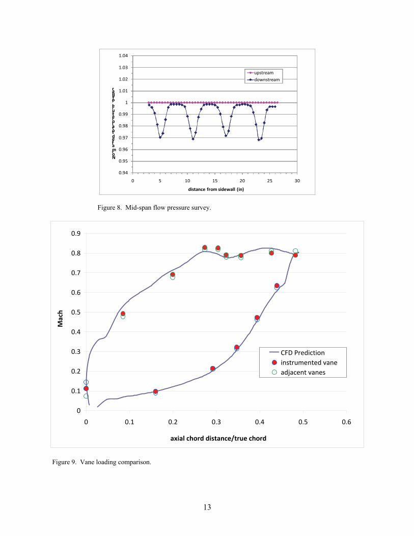
Figure 8 shows inlet and exit total pressure survey data for the cascade test section taken with a 3-hole pressure probe. The surveys confirm that the inlet flow was smooth and that the flow downstream of the vanes was periodic. Figure 9 shows the experimentally measured Mach number distribution on the mid-span of the tested vane, as well as the computational prediction for this vane in the cascade. The loading is typical of a vane of this type and the measured values agree with the prediction fairly well. Flow angle and endwall pressure measurements also were consistent with a well-conditioned periodic cascade. No inlet turbulence measurements were made during this test, however, many previous hot wire measurements were made in this facility with very similar inlet conditions. Based on these results, the inlet turbulence intensity was expected to be between 1 and 3 percent.
13
0.94
0.95
0.96
0.97
0.98
0.99
1
1.01
1.02
1.03
1.04
0 5 10 15 20 25 30
Normalized total pressure, P/Pbar
distance from sidewall (in)
upstreamdownstream
Figure 8. Mid-span flow pressure survey.
0
0.1
0.2
0.3
0.4
0.5
0.6
0.7
0.8
0.9
0 0.1 0.2 0.3 0.4 0.5 0.6
axial chord distance/true chord
Mach
CFD Predictioninstrumented vaneadjacent vanes
Figure 9. Vane loading comparison.

14
Figure 10 shows the measured heat transfer for the vane with no film cooling holes along with the Glenn-HT prediction. The graph shows Stanton number versus normalized surface distance for a Reynolds number based on true chord and exit conditions of 2.7 x 10⁶ and an exit Mach number of 0.725. The experimental data shows a local heat transfer maximum at the stagnation point with a nominal St value of 0.005. The heat transfer initially decreases on both the suction and pressure sides. On the suction side, the Stanton number initially decreases to a value of 0.004 at s/c of 0.055 and then quickly increases to a value around 0.01, showing a rather quick transition to a turbulent boundary layer. The heat transfer is highest on the suction side at an s/c of 0.2 to 0.4 as the flow accelerates around the vane curvature, and then is fairly constant and at a high level for most of the suction surface. The downstream suction surface heat transfer is nearly twice that of the stagnation point. On the pressure surface the Stanton number drops to a value about half that of the stagnation region, indicating a laminar boundary layer, and then monotonically rises gently moving further downstream. Note that the surface roughness of this vane was measured with a profilometer and the arithmetic mean peak height was roughly 350 microinches (8.89 μm), which could be considered fairly rough. The film cooled vane roughness was also measured and had a similar value.
0.000
0.005
0.010
0.015
0.020
‐1.0 ‐0.8 ‐0.6 ‐0.4 ‐0.2 0.0 0.2 0.4 0.6 0.8 1.0 1.2
Stanton Number
surface distance, s/c
no‐hole dataGlennHT prediction
suctionpressure
Figure 10. Stanton number for no film cooling case, Re = 2.7E6, Mach = 0.725.
The Glenn-HT heat transfer prediction matched the experimental values fairly well on the suction side but over-predicts on the pressure side. While the heat transfer trends are generally similar, the prediction also shows an earlier boundary layer transition to turbulent. The predicted stagnation Stanton number was roughly 60% higher than the experimental value. Generally the suction side heat transfer prediction matched the experiment within 10%, while on the pressure side the prediction over-predicted the measured values by roughly 100%. These results indicate that the k-ω turbulence model employed in Glenn-HT does a good job of predicting heat transfer when the boundary layer is turbulent but less so when the flow is laminar. There may be some
15
sensitivity of the surface heat transfer to the inlet turbulence intensity and length scale. The computational work was done with 8% turbulence intensity and 15% of vane true chord length scale that are larger than the experimental case. This, in concert with the use of the k-ω turbulence model which is essentially fully turbulent, may contribute to the over-prediction of Stanton number by the Glenn-HT code shown in figure 10.
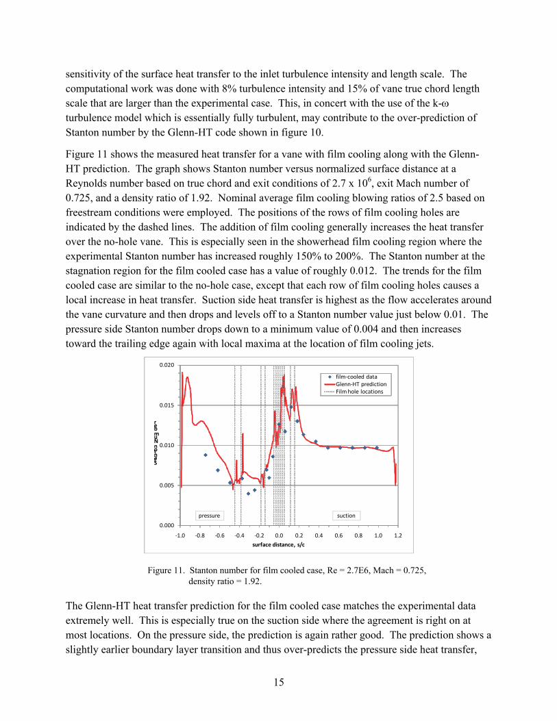
Figure 11 shows the measured heat transfer for a vane with film cooling along with the Glenn-HT prediction. The graph shows Stanton number versus normalized surface distance at a Reynolds number based on true chord and exit conditions of 2.7 x 10⁶, exit Mach number of 0.725, and a density ratio of 1.92. Nominal average film cooling blowing ratios of 2.5 based on freestream conditions were employed. The positions of the rows of film cooling holes are indicated by the dashed lines. The addition of film cooling generally increases the heat transfer over the no-hole vane. This is especially seen in the showerhead film cooling region where the experimental Stanton number has increased roughly 150% to 200%. The Stanton number at the stagnation region for the film cooled case has a value of roughly 0.012. The trends for the film cooled case are similar to the no-hole case, except that each row of film cooling holes causes a local increase in heat transfer. Suction side heat transfer is highest as the flow accelerates around the vane curvature and then drops and levels off to a Stanton number value just below 0.01. The pressure side Stanton number drops down to a minimum value of 0.004 and then increases toward the trailing edge again with local maxima at the location of film cooling jets.
0.000
0.005
0.010
0.015
0.020
‐1.0 ‐0.8 ‐0.6 ‐0.4 ‐0.2 0.0 0.2 0.4 0.6 0.8 1.0 1.2
Stanton Number
surface distance, s/c
film‐cooled dataGlenn‐HT predictionFilm hole locations
pressure suction
Figure 11. Stanton number for film cooled case, Re = 2.7E6, Mach = 0.725, density ratio = 1.92.
The Glenn-HT heat transfer prediction for the film cooled case matches the experimental data extremely well. This is especially true on the suction side where the agreement is right on at most locations. On the pressure side, the prediction is again rather good. The prediction shows a slightly earlier boundary layer transition and thus over-predicts the pressure side heat transfer,
16
but for most points the predicted Stanton numbers match the experimental values within 20%. It should be noted that the sharp peaks around the cooling holes seen in the prediction cannot be captured well with this experiment.
Conclusion
Heat transfer measurements were made on a commercially designed film cooled turbine vane employing a transient liquid crystal technique at near realistic engine conditions. We made comparisons with a prediction of flow and heat transfer of the same vane previously made using the Glenn-HT computation code.
1. The no-hole case shows high heat transfer on the suction side and much lower heat transfer on the pressure side, and indicates quick boundary layer transition on the suction side and mostly laminar flow on the pressure side.
2. Addition of film cooling enhances heat transfer relative to the no-hole vane baseline case. Film cooling jets cause a local increase in the heat transfer; this is especially true in the showerhead region.
3. Glenn-HT does a very good job predicting the heat transfer on the film cooled vane. The predicted Stanton number essentially matches much of the data well within the experimental uncertainty. The Glenn-HT code also does a fairly good job predicting the heat transfer on the no-hole vane. Comparison with the experimental data shows that the data trends are similar, and while the suction side shows adequate agreement, the pressure side is over-predicted by the computational model.
17
References
Abuaf, N.; Bunker, R. S.; Lee, C. P. Effects of Surface Roughness on Heat Transfer and Aerodynamic Performance of Turbine Airfoils. Journal of Turbomachinery 1998, 120, 522–529.
Arnone, A.; Liou, M.-S.; Povinelli, L. A. Multigrid Calculation of Three-Dimensional Viscous Cascade Flows; AIAA Paper 91-3238; 1991.
Ames, F. E. Experimental Study of Vane Heat Transfer and Film Cooling at Elevated Levels of Turbulence; NASA CR 198525; 1996.
Bohn, D. E.; Becker, V. J.; Rungen, A. U. Experimental and Numerical Conjugate Flow and Heat Transfer Investigation of a Shower-Head Cooled Turbine Guide Vane; ASME Paper 97-GT-15; 1997.
Chima, R. V. A k-ω Turbulence Model for Quasi-Three-Dimensional Turbomachinery Flows; NASA TM-107051; 1996.
Colban, W.; Gratton, A.; Thole, K. A.; Haendler, M. Heat Transfer and Film-Cooling Measurements on a Stator Vane With Fan-Shaped Cooling Holes. Journal of Turbomachinery 2006, 128, 53–61.
Cutbirth, J. M.; Bogard, D. G. Evaluation of Pressure Side Film Cooling With Flow and Thermal Field Measurements – Part I: Showerhead Effects. Journal of Turbomachinery 2002, 124, 670–677.
Ekkad, S. V.; Zapata, D.; Han, J. C. Heat Transfer Coefficients Over a Flat Surface with Air and CO2 Injection Through Compound Angle Holes Using a Transient Liquid Crystal Image Method. ASME Journal of Turbomachinery 1997, 119, 580–586.
Ethridge, M. I.; Cutbirth, J. M.; Bogard, D. G. Scaling of Performance for Varying Density Ratio Coolants on an Airfoil With Strong Curvature and Pressure Gradient Effects. Journal of Turbomachinery 2001, 123, 231–237.
Garg, V. K.; Rigby, D. L. Heat Transfer on a Film-Cooled Blade – Effect of Hole Physics; ASME Paper 98-GT-404; 1998.
Goldstein, R. J. Film Cooling. Advances in Heat Transfer 1971, 7, 321–379.
Gritsch, M.; Schulz, A.; Wittig, S. Adiabatic Wall Effectiveness Measurements of Film-Cooling Holes With Expanded Exits. ASME Journal of Turbomachinery 1998, 120, 549–556.
18
Haldeman, C. W.; Mathison, R. M.; Dunn, M. G.; Southworth, S.; Harral, J. W.; Heitland, G. Aerodynamic and Heat Flux Measurements in a Single Stage Fully Cooled Turbine- Part I: Experimental Approach; ASME Paper GT2006-90966; 2006.
Haldeman, C. W.; Mathison, R. M.; Dunn, M. G.; Southworth, S.; Harral, J. W.; Heitland, G. Aerodynamic and Heat Flux Measurements in a Single Stage Fully Cooled Turbine- Part II: Experimental Results; ASME Paper GT2006-90968; 2006.
Heidmann, J. D.; Rigby, D. L.; Ameri, A. A. A Three-Dimensional Coupled Internal/External Simulation of a Film-Cooled Turbine Vane. ASME Journal of Turbomachinery 2000, 122, 348-359. Also NASA TM 1999-209078.
Kline, S. J.; McClintock, F. A. Describing Uncertainties in Single-Sample Experiments. Mechanical Engineering 1953, 75, 3–8.
Menter, F. R. Zonal Two-Equation k-ω Turbulence Models for Aerodynamic Flows; AIAA Paper 93-2906, 1993.
Poinsatte, P. E.; Thurman, D. R.; Hippensteele, S. A. Heat Transfer in a Superelliptic Transition Duct; NASA TP-2007-214943, ARL-TR-4200; 2007.
Saumweber, C. Interaction of Film Cooling Rows: Effects of Hole Geometry and Row Spacing on the Cooling Performance Downstream of the Second Row of Holes. Journal of Turbomachinery 2004, 126, 237–246.
Schlichting, H. Boundary Layer Theory; McGraw-Hill, New York, 7th edition, pp. 312–313, 1979.
Steinthorsson, E.; Liou, M. S.; Povinelli, L. A. Development of an Explicit Multiblock/Multigrid Flow Solver for Viscous Flows in Complex Geometries; AIAA-93-2380; 1993.
Wilcox, D. C. Turbulence Modeling for CFD; DCW industries, Inc., LaCanada, CA, 1994a.
Wilcox, D. C. Simulation of Transition With a Two-Equation Turbulence Model. AIAA Journal 1994b, 32 (2), 247–255.
19
NO. OF COPIES ORGANIZATION 1 ADMNSTR ELEC DEFNS TECHL INFO CTR ATTN DTIC OCP 8725 JOHN J KINGMAN RD STE 0944 FT BELVOIR VA 22060-6218 1 DARPA ATTN IXO S WELBY 3701 N FAIRFAX DR ARLINGTON VA 22203-1714 1 CD OFC OF THE SECY OF DEFNS ATTN ODDRE (R&AT) THE PENTAGON WASHINGTON DC 20301-3080 1 US ARMY RSRCH DEV AND ENGRG CMND ARMAMENT RSRCH DEV AND ENGRG CTR ARMAMENT ENGRG AND TECHNLGY CTR ATTN AMSRD AAR AEF T J MATTS BLDG 305 ABERDEEN PROVING GROUND MD 21005-5001 1 US ARMY TRADOC BATTLE LAB INTEGRATION & TECHL DIRCTRT ATTN ATCD B 10 WHISTLER LANE FT MONROE VA 23651-5850 1 PM TIMS, PROFILER (MMS-P) AN/TMQ-52 ATTN B GRIFFIES BUILDING 563 FT MONMOUTH NJ 07703 1 US ARMY INFO SYS ENGRG CMND ATTN AMSEL IE TD F JENIA FT HUACHUCA AZ 85613-5300 1 COMMANDER US ARMY RDECOM ATTN AMSRD AMR W C MCCORKLE 5400 FOWLER RD REDSTONE ARSENAL AL 35898-5000
NO. OF COPIES ORGANIZATION 1 US ARMY RSRCH LAB ATTN AMSRD ARL CI OK TP TECHL LIB T LANDFRIED BLDG 4600 ABERDEEN PROVING GROUND MD 21005-5066 3 NASA LEWIS RSRCH CTR ATTN AMSRD ARL VT EC D THURMAN ATTN J HEIDMANN ATTN P POINSATTE 21000 BROOKPARK RD CLEVELAND OH 44135 1 US GOVERNMENT PRINT OFF DEPOSITORY RECEIVING SECTION ATTN MAIL STOP IDAD J TATE 732 NORTH CAPITOL ST NW WASHINGTON DC 20402 1 DIRECTOR US ARMY RSRCH LAB ATTN AMSRD ARL RO EV W D BACH PO BOX 12211 RESEARCH TRIANGLE PARK NC 27709 3 US ARMY RSRCH LAB ATTN AMSRD ARL CI OK T TECHL PUB ATTN AMSRD ARL CI OK TL TECHL LIB ATTN IMNE ALC IMS MAIL & RECORDS MGMT ADELPHI MD 20783-1197 TOTAL: 17 (1 ELECT, 1 CD, 15 HCS)

20
INTENTIONALLY LEFT BLANK.
Related Documents