Heat transfer characteristics of a two-phase thermosyphon heat exchanger Janusz T. Cie sli nski a, * , Artur Fiuk b a Gdansk University of Technology, Narutowicza 11/12, 80233 Gda nsk, Poland b SECESPOL Ltd., Gda nsk, Poland highlights < A prototype two-phase thermosyphon heat exchanger (TPTHEx) was proposed. < Performance of the TPTHEx was improved by the enhanced boiling tubes application. < Calculation algorithm of heat flux transferred in TPTHEx was proposed. article info Article history: Received 24 August 2011 Accepted 29 August 2012 Available online 7 September 2012 Keywords: Thermosyphon Enhanced boiling Tube bundle Heat exchanger abstract In this paper, a special design for a two-phase thermosyphon heat exchanger is proposed. This design features an evaporator tube bundle consisting of smooth, corrugated or porous coated tubes. The prototype heat exchanger consists of two horizontal cylindrical vessels connected by two risers and a downcomer. Tube bundles placed in the lower and upper cylinder function as an evaporator and a condenser. The operation of a two-phase thermosyphon is determined primarily by the evaporator’s performance. Therefore, an experimental investigation was conducted to determine the effects of the evaporator tube pitch (1.7d and 2.0d), the liquid head and fluid type on heat transfer in this two-phase thermosyphon heat exchanger. The investigation concerned six prototype heat exchangers operating in a heat flux range of 5e70 kW/m 2 . As working fluids, distilled water, methanol and refrigerant R-141b were utilised. The tested two-phase thermosyphon heat exchanger operates in a vacuum, and therefore the working liquids boiled in temperatures ranging from 24 C to 62 C. The obtained results indicate that the two-phase thermosyphon heat exchanger performs more effectively with an evaporator bundle comprising of porous coated tubes than with corrugated or smooth tubes. The evaporation heat transfer coefficient is strongly dependent on the liquid level above the top tube row (5 mm, 15 mm and 20 mm). Ó 2012 Elsevier Ltd. All rights reserved. 1. Introduction Two-phase thermosyphon heat exchangers (TPTHExs) are recuperators with an intermediate working fluid. This type of heat exchanger is used in a variety of heat transfer applications, but the heat transfer process mechanism in shell-side boiling and condensation heat exchangers is far from well-understood [1]. The TPTHEx is chiefly used for heat recovery from sewage or exhaust gases through the vaporisation of liquids at low tempera- tures. The TPTHEx protects installations against corrosion during the combustion of sulphured fuels because it is possible to select a working fluid and pressure such that the boiling temperature of the working fluid will always be higher than that of the exhaust gas’s dew point. In other words, if the temperature of the exhaust gases is lower than the temperature of the dew point, the TPTHEx operation stops. Used in heat recovery from sewage, the TPTHEx stops sewage from freezing at the evaporator outlet and, due to its double wall design, protects the heating installation from contamination. The TPTHEx can serve as a preheater and vaporiser of liquids at low temperatures, with vapour serving as the heating medium. Special care is required to prevent the freezing of the condensate, which flows inside the tubes of the evaporator. It is possible to select a working fluid and pressure inside the shell such that the boiling temperature of the working fluid will always be higher than the freezing temperature of the condensate. The two-phase thermosyphon (TPT) operates as follows: heat is supplied to the heating zone; the working fluid starts boiling and produces vapour, which moves to the condensing zone, where it loses heat; lastly, due to gravity, the condensate returns to the evaporator such the evaporationecondensation heat transfer cycle may be repeated. A characteristic feature of the TPT is that it operates as a thermal diode. This property means that the heat can be transported only in one direction e from the evaporator to the * Corresponding author. Tel.: þ48 58 347 1622; fax: þ48 58 347 13 83. E-mail addresses: [email protected] (J.T. Cie sli nski), afi[email protected] (A. Fiuk). Contents lists available at SciVerse ScienceDirect Applied Thermal Engineering journal homepage: www.elsevier.com/locate/apthermeng 1359-4311/$ e see front matter Ó 2012 Elsevier Ltd. All rights reserved. http://dx.doi.org/10.1016/j.applthermaleng.2012.08.067 Applied Thermal Engineering 51 (2013) 112e118

Welcome message from author
This document is posted to help you gain knowledge. Please leave a comment to let me know what you think about it! Share it to your friends and learn new things together.
Transcript

at SciVerse ScienceDirect
Applied Thermal Engineering 51 (2013) 112e118
Contents lists available
Applied Thermal Engineering
journal homepage: www.elsevier .com/locate/apthermeng
Heat transfer characteristics of a two-phase thermosyphon heat exchanger
Janusz T. Cie�sli�nski a,*, Artur Fiuk b
aGdansk University of Technology, Narutowicza 11/12, 80233 Gda�nsk, Polandb SECESPOL Ltd., Gda�nsk, Poland
h i g h l i g h t s
< A prototype two-phase thermosyphon heat exchanger (TPTHEx) was proposed.< Performance of the TPTHEx was improved by the enhanced boiling tubes application.< Calculation algorithm of heat flux transferred in TPTHEx was proposed.
a r t i c l e i n f o
Article history:Received 24 August 2011Accepted 29 August 2012Available online 7 September 2012
Keywords:ThermosyphonEnhanced boilingTube bundleHeat exchanger
* Corresponding author. Tel.: þ48 58 347 1622; faxE-mail addresses: [email protected] (J.T. Cie�sli�nski
1359-4311/$ e see front matter � 2012 Elsevier Ltd.http://dx.doi.org/10.1016/j.applthermaleng.2012.08.06
a b s t r a c t
In this paper, a special design for a two-phase thermosyphon heat exchanger is proposed. This designfeatures an evaporator tube bundle consisting of smooth, corrugated or porous coated tubes. Theprototype heat exchanger consists of two horizontal cylindrical vessels connected by two risers anda downcomer. Tube bundles placed in the lower and upper cylinder function as an evaporator anda condenser. The operation of a two-phase thermosyphon is determined primarily by the evaporator’sperformance. Therefore, an experimental investigation was conducted to determine the effects of theevaporator tube pitch (1.7d and 2.0d), the liquid head and fluid type on heat transfer in this two-phasethermosyphon heat exchanger. The investigation concerned six prototype heat exchangers operating ina heat flux range of 5e70 kW/m2. As working fluids, distilled water, methanol and refrigerant R-141bwere utilised. The tested two-phase thermosyphon heat exchanger operates in a vacuum, and thereforethe working liquids boiled in temperatures ranging from 24 �C to 62 �C. The obtained results indicate thatthe two-phase thermosyphon heat exchanger performs more effectively with an evaporator bundlecomprising of porous coated tubes than with corrugated or smooth tubes. The evaporation heat transfercoefficient is strongly dependent on the liquid level above the top tube row (5 mm, 15 mm and 20 mm).
� 2012 Elsevier Ltd. All rights reserved.
1. Introduction
Two-phase thermosyphon heat exchangers (TPTHExs) arerecuperators with an intermediate working fluid. This type of heatexchanger is used in a variety of heat transfer applications, but theheat transfer process mechanism in shell-side boiling andcondensation heat exchangers is far from well-understood [1].
The TPTHEx is chiefly used for heat recovery from sewage orexhaust gases through the vaporisation of liquids at low tempera-tures. The TPTHEx protects installations against corrosion duringthe combustion of sulphured fuels because it is possible to selecta working fluid and pressure such that the boiling temperature ofthe working fluid will always be higher than that of the exhaustgas’s dew point. In other words, if the temperature of the exhaustgases is lower than the temperature of the dew point, the TPTHEx
: þ48 58 347 13 83.), [email protected] (A. Fiuk).
All rights reserved.7
operation stops. Used in heat recovery from sewage, the TPTHExstops sewage from freezing at the evaporator outlet and, due to itsdouble wall design, protects the heating installation fromcontamination. The TPTHEx can serve as a preheater and vaporiserof liquids at low temperatures, with vapour serving as the heatingmedium. Special care is required to prevent the freezing of thecondensate, which flows inside the tubes of the evaporator. It ispossible to select a working fluid and pressure inside the shell suchthat the boiling temperature of the working fluid will always behigher than the freezing temperature of the condensate.
The two-phase thermosyphon (TPT) operates as follows: heat issupplied to the heating zone; the working fluid starts boiling andproduces vapour, which moves to the condensing zone, where itloses heat; lastly, due to gravity, the condensate returns to theevaporator such the evaporationecondensation heat transfer cyclemay be repeated. A characteristic feature of the TPT is that itoperates as a thermal diode. This property means that the heat canbe transported only in one direction e from the evaporator to the

J.T. Cie�sli�nski, A. Fiuk / Applied Thermal Engineering 51 (2013) 112e118 113
condenser. Two-phase thermosyphons can be divided into twomain groups: those with single tubes for a countercurrent flow ofliquid and vapour [2e4] and those with two-phase loops in whichthe evaporator is connected to the condenser (always above theevaporator) by a riser and a downcomer [5,6]. In vapour-dynamicthermosyphons [7], vapour and liquid flows are separated byawall, and heat transfer is realised in the gap between an inner andan outer tube. Vapour-dynamic thermosyphons and loop heatpipes [8] can provide the coupling between topping and bottomingsorption cycles [7]. In a thermosyphon tube, the heat flux is limitedby the counter flows of vapour and condensate [9]. In a two-phaseloop, the heat flux is limited by critical heat flux in two-phase flow[10,11].
The simplest thermosyphon consists of a vertical tube, which isheated and cooled from the outside. This design is a case of lateralheating and cooling of the casing. In another type of TPT thecondenser can be situated within the casing, and lateral heating isapplied to the casing [12]. In another type of thermosyphon tube,both the condenser and evaporator are placed within the casing.Such a solution allows for the utilisation of enhanced surfaces in thedesign of condensers and evaporators, such as the proposedTPTHEx.
Recent studies concern miniature thermosyphons used incooling applications for electronic components and higher heatduty heat exchangers for energy saving or heat recovery.
With regard to the miniature thermosyphons, Jouhara andRobinson [13] tested a short (200 mm), small-diameter (6 mm)thermosyphon with water and three Fluorinert liquids. Theyestablished that water outperformed the Fluorinert liquids. Addi-tionally, they found that their calculations of the evaporator sectionheat transfer coefficient compared well with experimental data, aswell as with pool boiling correlations commonly accepted inliterature.
Tsoi et al. [14] proposed a new design of a two-phase loopthermosyphon (TPLT) in the form of a thin(200 mm� 200mm� 3mm) plate. This TPLT operates horizontallyand vertically at sub-atmospheric pressure. The authors proposeda set of correlations for the overall thermal resistance prediction.
Filippeschi [15] tested the operation of a miniature periodictwo-phase thermosyphon (PTPT) with the same condenser andaccumulator and two evaporator geometries of different internalvolume (20� 10�6 m3 and 5�10�6 m3). A PTPT is awickless devicethat can operate opposite gravity. Filippeschi showed that thethermal resistance of a PPT is similar to that of a miniature LHP and
Fig. 1. Schematic view of th
during steady state operation equals 0.55 K/W with a heat load of110 W.
Firouzfar et al. [16] studied thermosyphons that are high heatduty heat exchangers. The authors established that the applicationof methanol-silver nanofluid as the working fluid in a TPTHEx savesenergy by 9e31% for cooling and 18e100% for reheating the airsupply stream in an air conditioning system.
Considerations for designing thermosyphons include predictionand control for oscillations encountered during different heat loads.Recently, Khazaee et al. [17] conducted experiments with two1000 mm copper pipes with 15 and 25 mm inside diameters usingmethanol as the working fluid to study geyser boiling in a two-phase closed thermosyphon. Their results show that the period ofgeyser boiling can be decreased by increasing the heat load andaspect ratio and increased by increasing the filling ratio.
Khodabandeh and Furberg [18] examined instabilities ina miniature two-phase loop thermosyphon. The authors estab-lished that flow and thermal instability increases as channel heightdecreases.
The purpose of this paper is to examine the effect of the evap-orator tube bundle geometry, the type of tube in the tube bundle(smooth, corrugated and porous coated) and the liquid level abovethe top tube row and the type of liquid (water, methanol or R-141b)on the overall performance of a TPTHEx.
2. Experiment
2.1. Experimental setup
The test stand consists of three main systems: the prototypeTPTHEx, the heating loop and the cooling water loop. The testfacility is capable of determining an overall heat transfer coefficientof the TPTHEx. A diagram of the test stand is shown in Fig. 1. Theheating and cooling water loops each contain a centrifugal pump,a flowmeter and a vent tank. A district heating network anda cooling tower are used as a heat source and heat sink, respec-tively. Heating and cooling water flow rates are controlled bya regulating valve and are measured by a Danfoss MAG 3100magnetic flowmeter, which is accurate to �0.25%. The averagetemperatures of the heating and cooling water at the inlets andoutlets of the TPTHEx evaporator and condenser tube bundles aremeasured using the Pt100 resistance temperature gauging devicewith an accuracy of �0.1 �C.
e experimental setup.
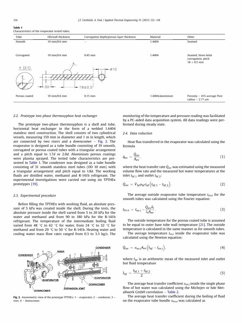
Table 1Characteristics of the evaporator tested tubes.
Tube OD/wall thickness Corrugation depth/porous layer thickness Material Other
Smooth 10 mm/0.6 mm e 1.4404 Seamed
Corrugated 10 mm/0.6 mm 0.45 mm 1.4404 Seamed, three-helixcorrugation, pitch18 � 0.5 mm
Porous coated 10 mm/0.6 mm 0.15 mm 1.4404/aluminium Porosity e 41% average Poreradius e 2.77 mm
J.T. Cie�sli�nski, A. Fiuk / Applied Thermal Engineering 51 (2013) 112e118114
2.2. Prototype two phase thermosyphon heat exchanger
The prototype two-phase thermosyphon is a shell and tube,horizontal heat exchanger in the form of a welded 1.4404stainless steel construction. The shell consists of two cylindricalvessels, measuring 159 mm in diameter and 1 m in length, whichare connected by two risers and a downcomer e Fig. 2. Theevaporator is designed as a tube bundle consisting of 19 smooth,corrugated or porous coated tubes with a triangular arrangementand a pitch equal to 1.7d or 2.0d. Aluminium porous coatingswere plasma sprayed. The tested tube characteristics are pre-sented in Table 1. The condenser was designed as a tube bundleconsisting of 31 smooth stainless steel tubes (OD 10 mm) witha triangular arrangement and pitch equal to 1.8d. The workingfluids are distilled water, methanol and R-141b refrigerant. Theexperimental investigations were carried out using six TPTHExprototypes [19].
2.3. Experimental procedure
Before filling the TPTHEx with working fluid, an absolute pres-sure of 5 kPa was created inside the shell. During the tests, theabsolute pressure inside the shell varied from 5 to 20 kPa for thewater and methanol and from 90 to 180 kPa for the R-141brefrigerant. The temperature of the intermediate boiling fluidvaried from 48 �C to 62 �C for water, from 24 �C to 32 �C formethanol and from 29 �C to 50 �C for R-141b. Heating water andcooling water mass flow rates ranged from 0.3 to 3.5 kg/s. The
Fig. 2. Axonometric view of the prototype TPTHEx; 1 e evaporator, 2 e condenser, 3 e
riser, 4 e downcomer.
monitoring of the temperature and pressure reading was facilitatedby a PC-aided data acquisition system. All data readings were per-formed during steady state.
2.4. Data reduction
Heat flux transferred in the evaporator was calculated using theformula
_qev ¼_Qev
Aev; (1)
where the heat transfer rate _Qev was estimated using the measuredvolume flow rate and the measured hot water temperatures at theinlet thf ;1 and outlet thf ;2:
_Qev ¼ _Vhfrhfchf�thf ;1 � thf ;2
�: (2)
The average outside evaporator tube temperature tev,o for thesmooth tubes was calculated using the Fourier equation:
tev;o ¼ tev;i �_QevdtltAev
: (3)
The outside temperature for the porous coated tube is assumedto be equal to outer base tube wall temperature [21]. The outsidetemperature is calculated in the same manner as for smooth tubes.
The average temperature tev,i inside the evaporator tube wascalculated using the Newton equation:
_Qev ¼ aev;iAev
�thf � tev;i
�; (4)
where thf is an arithmetic mean of the measured inlet and outlethot fluid temperature
thf ¼ thf ;1 þ thf ;22
: (5)
The average heat transfer coefficient aev,i inside the single phaseflow of hot water was calculated using the Michejev or hde Met-allwerk GmbH correlation e Table 2.
The average heat transfer coefficient during the boiling of fluidon the evaporator tube bundle aev,o was calculated as
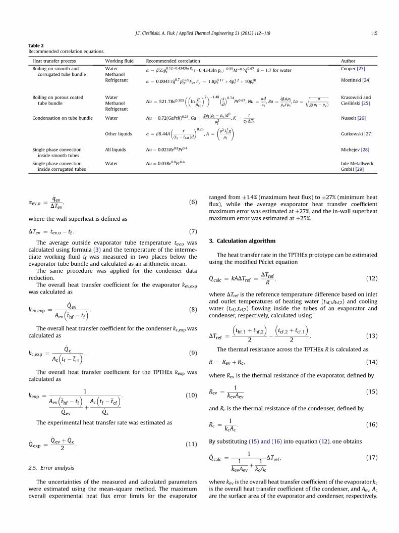
Table 2Recommended correlation equations.
Heat transfer process Working fluid Recommended correlation Author
Boiling on smooth andcorrugated tube bundle
Water a ¼ b55p0:12�0:4343ln Rpr ð�0:4343ln prÞ�0:55M�0:5 _q0:67, b ¼ 1.7 for water Cooper [23]
MethanolRefrigerant a ¼ 0:00417 _q0:7p0:69cr Fp, Fp ¼ 1:8p0:17r þ 4p1:2r þ 10p10r Mostinski [24]
Boiling on porous coatedtube bundle
WaterNu ¼ 521:7Bo0:305
��ln
ppcr
�2��1:48�sd
�0:74Pr0:67, Nu ¼ ad
ll, Bo ¼ _qLarl
rvrml, La ¼
ffiffiffiffiffiffiffiffiffiffiffiffiffiffiffiffiffiffiffiffiffis
gðrl � rvÞr Krasowski and
Cie�sli�nski [25]MethanolRefrigerant
Condensation on tube bundle Water Nu ¼ 0.72(GaPrK)0.25, Ga ¼ grlðrl � rvÞd3m2l
, K ¼ rcpDTs
Nusselt [26]
Other liquids a ¼ b6:44A�
rðtl � tsatÞd
�0:25
, A ¼ r2l3l gml
!Gutkowski [27]
Single phase convectioninside smooth tubes
All liquids Nu ¼ 0.021Re0.8Pr0.4 Michejev [28]
Single phase convectioninside corrugated tubes
Water Nu ¼ 0.03Re0.8Pr0.4 hde MetallwerkGmbH [29]
J.T. Cie�sli�nski, A. Fiuk / Applied Thermal Engineering 51 (2013) 112e118 115
aev;o ¼ _qevDTev
; (6)
where the wall superheat is defined as
DTev ¼ tev;o � tf : (7)
The average outside evaporator tube temperature tev,o wascalculated using formula (3) and the temperature of the interme-diate working fluid tf was measured in two places below theevaporator tube bundle and calculated as an arithmetic mean.
The same procedure was applied for the condenser datareduction.
The overall heat transfer coefficient for the evaporator kev,expwas calculated as
kev;exp ¼_Qev
Aev
�thf � tf
� : (8)
The overall heat transfer coefficient for the condenser kc,exp wascalculated as
kc;exp ¼_Qc
Ac
�tf � tcf
� : (9)
The overall heat transfer coefficient for the TPTHEx kexp wascalculated as
kexp ¼ 1
Aev
�thf � tf
�_Qev
þAc
�tf � tcf
�_Qc
: (10)
The experimental heat transfer rate was estimated as
_Qexp ¼_Qev þ _Qc
2: (11)
2.5. Error analysis
The uncertainties of the measured and calculated parameterswere estimated using the mean-square method. The maximumoverall experimental heat flux error limits for the evaporator
ranged from �1.4% (maximum heat flux) to �27% (minimum heatflux), while the average evaporator heat transfer coefficientmaximum error was estimated at �27%, and the in-wall superheatmaximum error was estimated at �25%.
3. Calculation algorithm
The heat transfer rate in the TPTHEx prototype can be estimatedusing the modified Péclet equation
_Qcalc ¼ kADTref ¼ DTrefR
; (12)
where DTref is the reference temperature difference based on inletand outlet temperatures of heating water (thf,1,thf,2) and coolingwater (tcf,1,tcf,2) flowing inside the tubes of an evaporator andcondenser, respectively, calculated using
DTref ¼�thf ;1 þ thf ;2
�2
��tcf ;2 þ tcf ;1
�2
: (13)
The thermal resistance across the TPTHEx R is calculated as
R ¼ Rev þ Rc; (14)
where Rev is the thermal resistance of the evaporator, defined by
Rev ¼ 1kevAev
(15)
and Rc is the thermal resistance of the condenser, defined by
Rc ¼ 1kcAc
: (16)
By substituting (15) and (16) into equation (12), one obtains
_Qcalc ¼ 11
kevAevþ 1kcAc
DTref ; (17)
where kev is the overall heat transfer coefficient of the evaporator,kcis the overall heat transfer coefficient of the condenser, and Aev, Acare the surface area of the evaporator and condenser, respectively.

J.T. Cie�sli�nski, A. Fiuk / Applied Thermal Engineering 51 (2013) 112e118116
The overall heat transfer coefficient of the evaporator wascalculated using the equation
kev ¼ 1
1aev;idev;i
þ 12lw
ln
dev;odev;i
!þ 1aev;odev;o
; (18)
where aev,i is the average heat transfer coefficient for water flowinginside smooth or corrugated tubes, aev,o is the bundle boilingaverage heat transfer coefficient, lw is the tube wall thermalconductivity and dev,i, dev,o are the inside and outside diameter of anevaporator tube, respectively.
The overall heat transfer coefficient of the condenser wascalculated using the equation
kc ¼ 1
1ac;idc;i
þ 12lw
ln
dc;odc;i
!þ 1ac;odc;o
; (19)
where ac,i is the average heat transfer coefficient for water flowinginside the smooth tubes, and ac,o is the bundle condensationaverage heat transfer coefficient.
A number of equations for calculations of the average heattransfer coefficients of single phase convection, bundle boiling andbundle condensation were tested to correlate the results in Ref.[20]. The recommended correlation equations are presented inTable 2.
4. Results and discussion
Fig. 3 shows the effect of the type of tube surface on evaporatorperformance during the boiling of R-141b refrigerant on the tubebundle with a 1.7d pitch. In this figure, the boiling curve for theporous coated evaporator tubes shifts to the left towards lowersuperheats. The phenomenon of nucleate boiling on porous coatedsurfaces commencing at lower wall superheat is known from otherstudies, such as [21]. Moreover, the porous coating creates a largenumber of stable, active nucleation sites; increasing the number of
Fig. 3. Boiling curves of R-141b on tube bundles: B e porous coated tubes,, e corrugated tubes, 6 e smooth tubes.
active boiling sites results in an improvement in heat transferperformance. The diameter of the mouth of the pore cavity definesthe nucleation radius and therefore thewall superheat at which thecavity becomes activated. Corrugation geometry (Table 1) is notconducive to nucleation, and only insignificant heat transferperformance improvement in the corrugated tube evaporator wasrecorded.
Fig. 4 shows boiling curves of the three tested fluids boiling onthe corrugated tube bundle with a 2.0d pitch. The best overallperformance of the evaporator was recorded with the distilledwater, regardless of tube type or pitch-to-diameter ratio. Thisphenomenon can be explained primarily by the distinctly higherlatent heat value of vapouring distilled water than in the cases ofmethanol and R-141b refrigerant. During the tests, with theincrease of heat duty, operating pressure rose from 9 to 18 kPa forwater, from 11 to 20 kPa for methanol and from 99 to 175 kPa forthe R-141b refrigerant.
The liquid head is one of the most important evaporator oper-ation parameters and depends on the construction of the evapo-rator. According to Thome [22] “an adequate liquid head has to bemaintained to obtain predictable performance and to avoid two phaseflow oscillations”. A problem for deeply immersed bundles can besubcooling of the fluid at the bottom of the bundle. Furthermore,the liquid head strongly affects the recirculation of liquid insidea shell and therefore affects the heat evaporator’s transfer perfor-mance. Fig. 5 shows the effect of the liquid level above the top tuberow on the TPTHEx overall heat transfer coefficient ko for threeevaporator heat flux values. In this case, the evaporator wascomprised of a corrugated tube bundle with a 1.7d pitch anda methanol as the working fluid. The overall heat transfer coeffi-cient increased with heat flux increase for a given liquid level abovethe top tube row. Regardless of heat flux, the lowest overall heattransfer coefficient value was recorded for the tests with a 5 mmliquid level above the top tube row. An increase in heat flux natu-rally decreases the liquid level. Thus, when the heat flux wasbetween 20 kW/m2 and 30 kW/m2, the top row of tubes wasuncovered and thermally almost inactive. Two upper tube rowswere uncovered when the heat flux was at 40 kW/m2, and thisuncovering resulted in a dramatic decrease in the overall heat
Fig. 4. Effect of various working fluids on evaporator performance (corrugated tubes);6 e water, B e R-141b, , e methanol.

Fig. 5. Effect of fluid head on TPTHEx overall heat transfer coefficient (methanol,corrugated tubes, 1.7d).
Fig. 6. Effect of tube pitch on overall heat transfer coefficient during boiling of wateron porous coated tube bundle; a) evaporator, b) thermosyphon heat exchanger; pitch:B e 2.0d, 6 e 1.7d.
Fig. 7. Heat transfer rate in TPTHEx e a comparison of predicted and experimentaldata; B e R-141b, , e methanol, 6 e water.
J.T. Cie�sli�nski, A. Fiuk / Applied Thermal Engineering 51 (2013) 112e118 117
transfer coefficient for the 5mm liquid level above the top tube row(point A in Fig. 5).
Tests with a 25mm liquid level above the top tube rowand threevalues of applied heat flux yielded an overall heat transfer coeffi-cient that was higher than for those with a 5 mm liquid level abovethe top tube row but was lower than for tests with a 15 mm liquidlevel above the top tube row. In the case of the 25 mm liquid levelabove the top tube row and the highest heat flux (40 kW/m2), all ofthe rows of tubes were submerged. Despite this finding, the recir-culation of liquid inside the evaporator shell was more restrainedthan in the case of the 15 mm liquid level above the top tube row.Therefore, the 15mm liquid level above the top tube rowappears tobe optimal for the TPTHEx evaporator with corrugated tubes whenusing methanol as the working fluid and applying the three testedheat fluxes.
Bundle boiling heat transfer is enhanced by nucleate boiling,where rising and expanding bubbles together with convectiveeffects produce greater turbulence and thus increase fluid recir-culation. However, the increased nucleation ability of porouscoating on evaporator tubes may produce too many excessivelylarge bubbles and may thus expose the upper rows to vapour anddecrease their heat transfer performance.
Fig. 6 illustrates the effect of an evaporator porous coated tubebundle pitch on the evaporator’s overall heat transfer coefficientkev,exp during the boiling of distilled water with heat flux _qev.Regardless of heat flux, the highest overall heat transfer coefficientwas obtained with the smallest tube pitch, i.e., 1.7d. The samebehaviour was observed for the corrugated and smooth tubebundles and other working fluids. These results clearly show theinfluence of convective effects on bundle boiling performance, evenin the case of porous coated tubes.
A comparison of the abovementioned analytical predictions andexperimental results is displayed in Fig. 7. The discrepancies ofapproximately 90% of the experimental points in relation to valuescalculated according to Eq. (12) are in the region of �40%.Considering the broad range of investigated parameters (threetypes of boiling surfaces, three working fluids, two pitch values)and the fact that the study involved boiling and condensationsimultaneously, we consider the agreement between experimentaland predicted values obtained by this study to be quite reasonable.
5. Conclusion
� A special design of a two-phase thermosyphon heat exchanger(TPTHEx), particularly for heat recovery from sewage orexhaust gases, has been proposed.
� The stable performance of the two-phase thermosyphon heatexchanger was recorded for three working fluids and threeliquid levels above the top tube row.
� The application of porous coated tubes results in better heattransfer characteristics of the tested two-phase thermosyphonheat exchanger.
� When lowwall superheat is preferable, the best option is to usea porous coated tube bundle, with R-141b refrigerant serving asthe working fluid, but for higher wall superheats, better heattransfer coefficients were obtained using water because of itsdifferent boiling regime.
� Regardless of tube type, the highest heat flux transfers wereobserved using the smallest tube pitch examined, i.e., 1.7d.

J.T. Cie�sli�nski, A. Fiuk / Applied Thermal Engineering 51 (2013) 112e118118
� A modified Péclet equation has been proposed for the calcu-lation of the TPTHEx heat transfer rate.
Acknowledgements
The authors wish to acknowledge the generous supportprovided by SECESPOL Ltd., Gda�nsk, Poland for producing theprototype two-phase thermosyphon heat exchangers.
Nomenclature
A heat transfer area [m2]cp specific heat [J/kg K]d diameter [m]g acceleration due to gravity [m/s2]k overall heat transfer coefficient [W/m2 K]p pressure [Pa]_Q heat transfer rate [W]_q heat flux [W/m2]r latent heat of evaporation [kJ/kg]s pitch [m]t temperature [�C]a heat transfer coefficient [W/m2 K]m viscosity [Pa s]l thermal conductivity [W/m K]r density [kg/m3]s surface tension [N/m]
Subscriptc condensercf cold fluidev evaporatorexp experimentalf intermediate working fluidhf hot fluidi insideo outsideref referencet tubew wall1 inlet2 outlet
References
[1] L.S. Pioro, I.L. Pioro, Industrial Two-Phase Thermosyphons, Begell House Inc.,New York, Wallingford (UK), 1997.
[2] M. Bezrodny, J. Goscik, Thermosyphon heat exchangers, Refrigeration Air-Conditioning Eng. 1 (1997) 5e10 (in Polish).
[3] D. Chisholm, Heat Exchangers Design Handbook, Part 3, Thermal andHydraulic Design of Heat Exchangers, Begell House Inc., New York, Wall-ingford (UK), 1998 (Chapter 3.10.1).
[4] S. Khandekar, M. Groll, Insights into the performance models of closed looppulsating heat pipes and some design hints, in: Proc. 18th National & 7th
ISHMT-ASME Heat and Mass Transfer Conference, IIT Guwahati, India, 2006,Paper No: G-440.
[5] N. Gavotti, F. Polá�sek, Thermal control of electronic components by means oftwo-phase thermosyphons, in: Proc. of Eurotherm Seminar No. 6, Single andTwo-Phase Natural Circulation, Genoa, Italy, 1999, pp. 229e238.
[6] R. Khodabandeh, B. Palm, An experimental investigation of the influence ofsystem pressure on the boiling heat transfer coefficient in closed two-phasethermosyphon loop, in: Proc. of the 5th ExHFT World Conference, Thessalo-niki, Greece, 2001, pp. 191e196.
[7] L.L. Vasiliev, Heat pipes in modern heat exchangers, Appl. Therm. Eng. 25(2005) 1e19.
[8] L.L. Vasiliev, Micro and miniature heat pipes e electronic component coolers,Appl. Therm. Eng. 28 (2008) 266e273.
[9] M. Monde, Analytical study of critical heat flux in two-phase thermosyphon:relationship between maximum falling liquid and critical heat flux, ASME J.Heat Transfer 118 (1996) 422e428.
[10] A.I. Leontiev, O.O. Milman, V.A. Fedorov, Ultimate loads with water boiling inthe vertical channels under natural circulation conditions, J. Eng. Phys. 48(1985) 621e628.
[11] A. Baars, A. Delgado, Multiple modes of a natural circulation evaporator,J. Heat Mass Transfer 49 (2006) 2304e2314.
[12] F.M. Chernomurov, Operational principle and potential application ofcondensation-gas cooling apparatuses, J. Eng. Phys. Thermophys. 36 (1979)1113e1114 (in Russian).
[13] H. Jouhara, A.J. Robinson, Experimental investigation of small diameter two-phase closed, thermosyphons charged with water, FC-84, FC-77 and FC-3283, Appl. Therm. Eng. 30 (2010) 201e211.
[14] V. Tsoi, S.W. Chang, K.F. Chiang, C.C. Huang, Thermal performance of plate-type loop thermosyphon at sub-atmospheric pressures, Appl. Therm. Eng.31 (2011) 2556e2567.
[15] S. Filippeschi, Comparison between miniature periodic two-phase thermo-syphons and miniature LHP applied to electronic cooling equipment, Appl.Therm. Eng. 31 (2011) 795e802.
[16] E. Firouzfar, M. Soltanieh, S.H. Noie, S.H. Saidi, Energy saving in HVAC systemsusing nanofluid, Appl. Therm. Eng. 31 (2011) 1543e1545.
[17] I. Khazaee, R. Hosseini, S.H. Noie, Experimental investigation of effectiveparameters and correlation of geyser boiling in a two-phase closed thermo-syphon, Appl. Therm. Eng. 30 (2010) 406e412.
[18] R. Khodabandeh, R. Furberg, Instability, heat transfer and flow regime ina two-phase flow thermosyphon loop at different diameter evaporatorchannel, Appl. Therm. Eng. 30 (2010) 1107e1114.
[19] J.T. Cie�sli�nski, A. Fiuk, Thermosyphon heat exchanger, Polish Patent PL 192757(2006).
[20] A. Fiuk, Influence of geometrical and thermophysical parameters on two-phase thermosyphon performance, PhD thesis, GUT, Gdansk, Poland, 2009(in Polish).
[21] J.T. Cie�sli�nski, Nucleate pool boiling on porous metallic coatings, Exp. Therm.Fluid Sci. 25 (2002) 557e564.
[22] J.R. Thome, Enhanced Boiling Heat Transfer, Hemisphere, NY, 1990, pp. 284.[23] M.G. Cooper, Heat flow in saturated nucleate pool boiling e a wide-
ranging examination using reduced properties, Adv. Heat Transfer 16(1984) 157e239.
[24] I.L. Mostinski, Application of the rule of corresponding states for the calcu-lation of heat transfer critical heat flux, Teploenergetika 4 (1963) 66e71 (inRussian).
[25] K. Krasowski, J.T. Cie�sli�nski, Heat transfer during pool boiling of water,methanol and R141b on porous coated horizontal tube bundles, in: HEAT2011, the 6th International Conference on Transport Phenomena in Multi-phase Systems June 28eJuly 2, 2011, Ryn, Poland, pp. 279e284.
[26] W. Nusselt, Steam condensation, Zeitschr. Ver. Deutsch. Ing. 60 (1916) 542e546. and 569e575 (in German).
[27] K. Gutkowski, Refrigeration e Selected Numerical Problems, WNT, Warsaw,1972 (in Polish).
[28] M.A. Michejev, Fundamentals of Heat Transfer, State Power Energy Publishers,Moscow, 1949 (in Russian).
[29] Heat Transfer Technology Information, Heat Transfer during Single PhaseFluid Flow through Twisted Tubes, Hde Metallwerk GmbH, Menden,Germany, 1994 (in German).
Related Documents